KR20110129411A - Assay strips and methods of making them - Google Patents
Assay strips and methods of making themDownload PDFInfo
- Publication number
- KR20110129411A KR20110129411AKR1020117022002AKR20117022002AKR20110129411AKR 20110129411 AKR20110129411 AKR 20110129411AKR 1020117022002 AKR1020117022002 AKR 1020117022002AKR 20117022002 AKR20117022002 AKR 20117022002AKR 20110129411 AKR20110129411 AKR 20110129411A
- Authority
- KR
- South Korea
- Prior art keywords
- channel
- plane
- substrate
- solution
- hollow
- Prior art date
- Legal status (The legal status is an assumption and is not a legal conclusion. Google has not performed a legal analysis and makes no representation as to the accuracy of the status listed.)
- Granted
Links
Images


Classifications
- G—PHYSICS
- G01—MEASURING; TESTING
- G01N—INVESTIGATING OR ANALYSING MATERIALS BY DETERMINING THEIR CHEMICAL OR PHYSICAL PROPERTIES
- G01N33/00—Investigating or analysing materials by specific methods not covered by groups G01N1/00 - G01N31/00
- G01N33/48—Biological material, e.g. blood, urine; Haemocytometers
- G01N33/50—Chemical analysis of biological material, e.g. blood, urine; Testing involving biospecific ligand binding methods; Immunological testing
- G01N33/53—Immunoassay; Biospecific binding assay; Materials therefor
- G01N33/543—Immunoassay; Biospecific binding assay; Materials therefor with an insoluble carrier for immobilising immunochemicals
- G01N33/54366—Apparatus specially adapted for solid-phase testing
- C—CHEMISTRY; METALLURGY
- C12—BIOCHEMISTRY; BEER; SPIRITS; WINE; VINEGAR; MICROBIOLOGY; ENZYMOLOGY; MUTATION OR GENETIC ENGINEERING
- C12Q—MEASURING OR TESTING PROCESSES INVOLVING ENZYMES, NUCLEIC ACIDS OR MICROORGANISMS; COMPOSITIONS OR TEST PAPERS THEREFOR; PROCESSES OF PREPARING SUCH COMPOSITIONS; CONDITION-RESPONSIVE CONTROL IN MICROBIOLOGICAL OR ENZYMOLOGICAL PROCESSES
- C12Q1/00—Measuring or testing processes involving enzymes, nucleic acids or microorganisms; Compositions therefor; Processes of preparing such compositions
- C12Q1/25—Measuring or testing processes involving enzymes, nucleic acids or microorganisms; Compositions therefor; Processes of preparing such compositions involving enzymes not classifiable in groups C12Q1/26 - C12Q1/66
- G—PHYSICS
- G01—MEASURING; TESTING
- G01N—INVESTIGATING OR ANALYSING MATERIALS BY DETERMINING THEIR CHEMICAL OR PHYSICAL PROPERTIES
- G01N33/00—Investigating or analysing materials by specific methods not covered by groups G01N1/00 - G01N31/00
- G01N33/48—Biological material, e.g. blood, urine; Haemocytometers
- G01N33/50—Chemical analysis of biological material, e.g. blood, urine; Testing involving biospecific ligand binding methods; Immunological testing
- G01N33/68—Chemical analysis of biological material, e.g. blood, urine; Testing involving biospecific ligand binding methods; Immunological testing involving proteins, peptides or amino acids
Landscapes
- Health & Medical Sciences (AREA)
- Life Sciences & Earth Sciences (AREA)
- Immunology (AREA)
- Engineering & Computer Science (AREA)
- Chemical & Material Sciences (AREA)
- Molecular Biology (AREA)
- Biomedical Technology (AREA)
- Hematology (AREA)
- Urology & Nephrology (AREA)
- Biochemistry (AREA)
- Analytical Chemistry (AREA)
- Microbiology (AREA)
- General Health & Medical Sciences (AREA)
- Biotechnology (AREA)
- Physics & Mathematics (AREA)
- Medicinal Chemistry (AREA)
- Food Science & Technology (AREA)
- General Physics & Mathematics (AREA)
- Pathology (AREA)
- Cell Biology (AREA)
- Proteomics, Peptides & Aminoacids (AREA)
- Organic Chemistry (AREA)
- Zoology (AREA)
- Wood Science & Technology (AREA)
- Biophysics (AREA)
- Bioinformatics & Cheminformatics (AREA)
- General Engineering & Computer Science (AREA)
- Genetics & Genomics (AREA)
- Apparatus Associated With Microorganisms And Enzymes (AREA)
- Investigating Or Analysing Biological Materials (AREA)
- Automatic Analysis And Handling Materials Therefor (AREA)
- Measuring Or Testing Involving Enzymes Or Micro-Organisms (AREA)
Abstract
Translated fromKoreanDescription
Translated fromKorean본 발명은 분석 스트립에 관한 것이고, 더욱 자세하게는, 생화학적 및 면역학적 에세이(assay)용 분석 스트립에 관한 것이다.The present invention relates to assay strips and, more particularly, to assay strips for biochemical and immunological assays.
분석 스트립은 생화학적 시험 및 면역학적 시험에서 통상적으로 사용된다. 전형적인 분석 스트립은 움푹 들어간(sunken) 채널 또는 마이크로채널(micro-channels)을 갖도록 형성되고 소수성 및 친수성 표면 처리에 의해 가공된 기판 또는 베이스(base)를 갖는다. 상기 채널은 비-흡착성 물질과 접해 있고, 시험될 유체 샘플은 예컨대, 단백질 또는 탄수화물을 함유하는 통상 점성 조성물이기 때문에, 채널을 유동하는 유체 샘플은 채널의 표면에 접착되는 경향이 있어 충분히 반응될 수 없다. 따라서, 유체 샘플은 소비되고, 그렇지 않으면 시험 결과의 오류를 초래한다.Assay strips are commonly used in biochemical and immunological tests. Typical assay strips have substrates or bases formed with sunken channels or micro-channels and processed by hydrophobic and hydrophilic surface treatments. Since the channel is in contact with a non-adsorbent material and the fluid sample to be tested is a conventional viscous composition containing, for example, protein or carbohydrates, the fluid sample flowing through the channel tends to adhere to the surface of the channel and can be fully reacted. none. Thus, the fluid sample is consumed, otherwise it leads to an error in the test results.
또한, 통상의 분석 스트립은 유체 전달을 용이하게 하기 위하여 마이크로채널을 구비하고 있고, 상기 마이크로채널은 유체 샘플이 채널을 거쳐 반응/검출 영역으로 가도록 모세관 작용을 유발한다. 다르게는, 유체 샘플은 예컨대, 가압 수단 또는 진공- 또는 부압-생성수단에 의해 제공되는 구동력에 의해 채널에 도입될 수 있으므로, 채널을 통하여 유체 샘플을 추진시킨다. 유체 전달을 증진하는 다른 방법은 1 이상의 마이크로-액츄에이터(micro-actuators) 또는 마이크로-밸브를 갖는 채널을 제공하는 것으로, 이들을 통하여 유체 샘플이 성공적으로 통과하여 반응/검출 영역에 도달한다. 그러나, 상술한 어떤 방법에서든, 다양한 크기의 공기 기포가 생성되어, 샘플이 채널에 도입된 후에 시험될 유체 샘플에 들어가거나 또는 연행되는 경향이 있다. 이들 기포는, 채널 막힘을 유발할 때, 시험 오류를 초래하거나 또는 심지어 시험 실패를 초래할 수 있다. 더구나, 마이크로-액츄에이터 또는 마이크로-밸브의 설치는 분석 스트립의 설계와 비용에 대하여 전반적인 어려움을 부가한다.In addition, conventional assay strips have microchannels to facilitate fluid delivery, which induce capillary action to allow fluid samples to pass through the channels to the reaction / detection zone. Alternatively, the fluid sample may be introduced into the channel by, for example, a driving force provided by the pressurizing means or the vacuum- or negative pressure-generating means, thereby forcing the fluid sample through the channel. Another method of enhancing fluid delivery is to provide a channel with one or more micro-actuators or micro-valve through which the fluid sample successfully passes and reaches the reaction / detection zone. However, in any of the methods described above, air bubbles of various sizes are generated, which tend to enter or entrain the fluid sample to be tested after the sample is introduced into the channel. These bubbles can cause test errors or even test failures when causing channel blockage. Moreover, the installation of a micro-actuator or micro-valve adds overall difficulty to the design and cost of the assay strip.
게다가, 통상의 분석 스트립을 제조하는 동안, 채널 또는 미세유체-채널은, 몰드(mold)의 조기(early) 마모 및 인열과 관련되어서 분석 스트립 제조에서 전체 비용 상승을 유발하는 미세가공(micro-machining) 또는 LIGA("Lithographie GalVanoformung Abformung" 또는 용어로는 "Lithography Electroforming Micro Molding"의 약어)와 같은 값비싼 다이 제조 공정을 이용하여 마이크로-사출성형 또는 임프린팅(imprinting)에 의해 기판 상에 흔히 형성된다.In addition, during the manufacture of conventional assay strips, the channels or microfluidic-channels are associated with the early wear and tear of the mold, resulting in an increase in the overall cost in assay strip manufacture. ) Or LIGA (“Lithographie GalVanoformung Abformung” or terminology “Lithography Electroforming Micro Molding”) is often formed on a substrate by micro-injection molding or imprinting using an expensive die fabrication process. .
따라서, 채널 중에 있는 유체 샘플의 잔류물이 시험을 불편하고 시간 소모적으로 만든다. 또한, 전통적인 분석 스트립의 제조 비용은 보통 상당히 많이 든다.Thus, residues of fluid samples in the channel make the test inconvenient and time consuming. In addition, the manufacturing cost of traditional assay strips is usually quite high.
발명의 요약Summary of the Invention
상술한 단점을 극복하기 위하여, 본 발명은 기판 및 채널을 포함하는 분석 스트립을 제공한다. 상기 기판은 평면(flat surface)을 갖고 상기 채널은 소정 패턴으로 상기 평면 위에 형성된다. 채널의 표면은 기판의 표면보다 낮지 않다. 상기 채널은 중공-매트릭스(hollow-matrix) 형태를 갖고 상기 채널은 기판의 평면보다 더 친수성이다. 상기 스트립은 또한 중공-매트릭스 내에 형성된 반응 물질을 함유한다.In order to overcome the above disadvantages, the present invention provides an analysis strip comprising a substrate and a channel. The substrate has a flat surface and the channel is formed above the plane in a predetermined pattern. The surface of the channel is not lower than the surface of the substrate. The channel has a hollow-matrix form and the channel is more hydrophilic than the plane of the substrate. The strip also contains a reaction material formed in the hollow-matrix.
따라서, 본 발명의 주요 목적은 중공-매트릭스 형태의 채널을 포함하는 분석 스트립을 제공하는 것이다. 상기 채널은 전통적인 미세유체(microfluidic) 채널과는 대조적으로 샘플의 잔류량이 적고, 다분석물(multi-analytes) 검출 시험에 필요한 샘플 부피가 적은 것이 실현된다.It is therefore a primary object of the present invention to provide an assay strip comprising a channel in the form of a hollow matrix. In contrast to traditional microfluidic channels, the channel has a low amount of residual sample and a small sample volume required for multi-analytes detection testing.
본 발명의 다른 목적은 일정한 부피 흡수성능을 갖는 흡수성 니트로셀룰로오스 층을 포함하여서 니트로셀룰로오스 층의 부피 제어를 통하여 정량적 에세이가 실시되게 하는 분석 스트립을 제공하는 것이다.It is another object of the present invention to provide an assay strip that includes an absorbent nitrocellulose layer having a constant volume absorbency, thereby allowing quantitative assays to be carried out through volume control of the nitrocellulose layer.
본 발명의 또 다른 목적은 중공-매트릭스 배열구성의 흡수성 니트로셀룰로오스 층을 가져서, 유체 샘플이 중공 매트릭스를 통하여 유동할 때 유체 샘플 중의 공기 기포를 파괴할 수 있을 뿐만 아니라 이들 기포가 기판의 채널 또는 미세유체 채널을 막지 않게 할 수 있는 분석 스트립을 제공하는 것이다. 따라서, 정량 에세이의 정확한 결과를 확실히 얻을 수 있다.Another object of the present invention is to have a hollow-matrix array of absorbent nitrocellulose layers, which not only can destroy air bubbles in the fluid sample when the fluid sample flows through the hollow matrix, but also these bubbles can cause the channel or micro It is to provide an analysis strip that can prevent the fluid channel from blocking. Thus, accurate results of quantitative assays can be obtained with certainty.
본 발명의 다른 목적은 몰딩, 사출성형, 임프린트의 이용 또는 미세가공 또는 리소그래피-전주(electroforming)-마이크로-몰딩과 같은 값비싼 다이 제조 공정을 이용하는 대신, 기판의 평면 상에 소정 패턴으로 형성된 채널을 포함하므로, 분석 스트립의 대량 제조 비용을 절감할 수 있는 분석 스트립을 제공하는 것이다.Another object of the present invention is to provide a channel formed in a predetermined pattern on the plane of the substrate, instead of using an expensive die fabrication process such as molding, injection molding, imprinting or microfabrication or lithography-electroforming-micro-molding. The present invention provides an analysis strip that can reduce the cost of mass production of the analysis strip.
본 발명의 다른 목적은 제조 비용이 감소되고 측정 정확도가 개선된 분석 스트립을 제조할 수 있는 제조 방법을 제공하는 것이다.Another object of the present invention is to provide a manufacturing method capable of producing an analysis strip with reduced manufacturing cost and improved measurement accuracy.
본 발명의 분석 스트립에서, 상기 채널의 표면은 기판의 평면보다 더 높다.In the assay strip of the present invention, the surface of the channel is higher than the plane of the substrate.
본 발명의 분석 스트립에서, 상기 채널의 단면은 평면으로부터 용기부(rise)를 갖는다.In the assay strip of the invention, the cross section of the channel has a rise from a plane.
본 발명의 분석 스트립에서, 상기 채널은 니트로셀룰로오스 및 유리섬유(fiberglass)로 이루어진 군으로부터 선택된 물질로 제조된다.In the assay strip of the present invention, the channel is made of a material selected from the group consisting of nitrocellulose and fiberglass.
본 발명의 분석 스트립에서, 상기 채널은 리소그래픽 인쇄, 포토그라비아, 철판인쇄, 스크린-인쇄, 라인 마킹, 잉크젯 또는 침지로 이루어진 군으로부터 선택된 것에 따라서 평면 상에 형성된다.In the assay strip of the present invention, the channel is formed on a plane according to the one selected from the group consisting of lithographic printing, photogravure, iron printing, screen-printing, line marking, inkjet or dipping.
본 발명의 분석 스트립에서, 상기 채널은 복수의 분기 채널(branch channel)을 더 포함한다.In the assay strip of the present invention, the channel further comprises a plurality of branch channels.
본 발명의 분석 스트립에서, 적어도 1개의 상기 분기 채널은 돔형, 직사각형 및 섬모양(island)으로 이루어진 군으로부터 선택된 형상을 갖는 연장된 영역을 더 포함한다.In the assay strip of the present invention, the at least one branch channel further comprises an extended region having a shape selected from the group consisting of dome, rectangle and island.
본 발명의 분석 스트립에서, 상기 채널은 용액으로부터 건조 및 고화되어 중공-매트릭스를 형성하여 제조되며, 상기 용액은 니트로셀룰로오스 용액 및 유리섬유 용액으로 이루어진 군으로부터 선택된다.In the assay strip of the present invention, the channel is prepared by drying and solidifying from a solution to form a hollow matrix, the solution being selected from the group consisting of nitrocellulose solution and glass fiber solution.
본 발명의 분석 스트립에서, 상기 기판은 생체적합성(biocompatible) 재료로 제조된다.In the assay strip of the present invention, the substrate is made of a biocompatible material.
본 발명의 분석 스트립에서, 상기 기판은 유연성(flexible)이다.In the assay strip of the present invention, the substrate is flexible.
본 발명의 분석 스트립에서, 상기 반응 물질은 반응 용액을 채널에 주입한 다음 그 반응 용액을 건조시키는 것에 의해 중공-매트릭스 형태에 혼입된다.In the assay strip of the present invention, the reactants are incorporated into the hollow-matrix form by injecting the reaction solution into the channel and then drying the reaction solution.
본 발명의 분석 스트립에서, 반응 용액의 건조는 공기건조 또는 동결건조에 의해 실시된다.In the assay strip of the present invention, the reaction solution is dried by air drying or lyophilization.
본 발명의 분석 스트립에서, 상기 반응 물질은 화학 시약 및 효소 시약으로부터 선택된다.In the assay strip of the present invention, the reactants are selected from chemical reagents and enzyme reagents.
본 발명의 분석 스트립에서, 상기 반응 물질은 항체 및 화학 시약으로부터 선택된다.In the assay strip of the present invention, the reactants are selected from antibodies and chemical reagents.
본 발명의 분석 스트립은 상기 평면과 채널 사이에 형성된 한 쌍의 평면 전극(planar electrode)를 더 포함한다.The assay strip of the present invention further comprises a pair of planar electrodes formed between the plane and the channel.
본 발명의 분석 스트립은 상기 채널 상에 형성된 스택된(stacked) 채널을 더 포함한다.The assay strip of the present invention further comprises a stacked channel formed on the channel.
본 발명의 다른 목적은,Another object of the present invention,
평면을 갖는 기판을 제공하고; 상기 평면에 용액을 소정 패턴에 따라 도포하며; 상기 도포된 용액을 건조시켜, 채널의 표면이 평면보다 낮지 않고, 채널이 중공-매트릭스 형태를 가지며, 채널이 기판의 평면보다 더 친수성이 되게 하는 방식으로 소정 패턴의 채널을 형성하고; 및 반응 물질을 제공하여 중공 매트릭스 형태에 혼입되게 하는 것을 포함하는, 분석 스트립의 제조 방법을 제공하는 것이다.Providing a substrate having a plane; Applying a solution to the plane according to a predetermined pattern; Drying the applied solution to form a pattern of channels in such a way that the surface of the channel is not lower than the plane, the channel has a hollow-matrix form, and the channel is more hydrophilic than the plane of the substrate; And providing a reactant to be incorporated into the hollow matrix form.
본 발명의 다른 목적은,Another object of the present invention,
평면을 갖는 기판을 제공하고; 소정 패턴으로 음각된(engraved) 마스크를 제공하며; 상기 마스크를 탈착가능하게 기판에 접착시키고; 소정 패턴으로 음각된 곳에 용액을 도포하며; 도포된 용액을 건조시키고; 마스크를 제거하여, 채널의 표면은 기판의 평면보다 더 낮지 않고, 채널이 중공-매트릭스 형태를 가지며, 채널이 기판의 평면보다 더 친수성이 되게 하는 방식으로 소정 패턴을 갖는 채널을 형성하며; 및 반응물질을 제공하여 그 반응 물질을 중공-매트릭스 형태에 혼입시키는 것을 포함하는, 분석 스트립의 제조 방법을 제공하는 것이다.Providing a substrate having a plane; Providing a mask engraved in a predetermined pattern; Detachably attaching the mask to a substrate; Applying the solution in a recess in a predetermined pattern; The applied solution is dried; Removing the mask so that the surface of the channel is not lower than the plane of the substrate, and the channel has a hollow-matrix form and forms a channel having a predetermined pattern in such a manner that the channel becomes more hydrophilic than the plane of the substrate; And providing a reactant to incorporate the reactant in a hollow-matrix form.
본 발명의 제조 방법에서, 상기 채널의 표면은 기판의 평면보다 더 높다.In the manufacturing method of the present invention, the surface of the channel is higher than the plane of the substrate.
본 발명의 제조 방법에서, 상기 채널의 단면은 평면으로부터 용기부를 갖는다.In the manufacturing method of the present invention, the cross section of the channel has a container portion from the plane.
본 발명의 제조 방법에서, 상기 용액은 리소그래픽 인쇄, 포토그라비아, 철판인쇄, 스크린 인쇄, 라인 마킹, 잉크젯/분무, 캐스팅, 또는 침지에 의하여 도포될 수 있다.In the production method of the present invention, the solution may be applied by lithographic printing, photogravure, iron printing, screen printing, line marking, inkjet / spraying, casting, or dipping.
본 발명의 제조 방법에서, 상기 채널은 복수의 분기(branch) 채널을 더 포함한다.In the manufacturing method of the present invention, the channel further comprises a plurality of branch channels.
본 발명의 제조 방법에서, 적어도 1개의 상기 분기 채널은 돔형, 직사각형 및 섬모양으로 이루어진 군으로부터 선택된 형상을 갖는 연장된 영역을 더 포함한다.In the manufacturing method of the present invention, the at least one branch channel further comprises an extended region having a shape selected from the group consisting of dome, rectangle and island shape.
본 발명의 제조 방법에서, 상기 채널은 용액으로부터 건조 및 고화되어 중공-매트릭스를 형성하여 제조되며, 상기 용액은 니트로셀룰로오스 용액 및 유리섬유 용액으로 이루어진 군으로부터 선택된다.In the production method of the present invention, the channel is prepared by drying and solidifying from a solution to form a hollow matrix, the solution being selected from the group consisting of nitrocellulose solution and glass fiber solution.
본 발명의 제조 방법에서, 상기 기판은 생체적합성 재료로 제조된다.In the manufacturing method of the present invention, the substrate is made of a biocompatible material.
본 발명의 제조 방법에서, 상기 기판은 유연성이다.In the manufacturing method of the present invention, the substrate is flexible.
본 발명의 제조 방법에서, 상기 반응 물질은 반응 용액을 채널에 주입한 다음 그 반응 용액을 건조시키는 것에 의해 중공-매트릭스 형태에 혼입된다.In the production method of the present invention, the reactant material is incorporated into the hollow-matrix form by injecting the reaction solution into the channel and then drying the reaction solution.
본 발명의 제조 방법에서, 반응 용액의 건조는 공기건조 또는 동결건조에 의해 실시된다.In the production method of the present invention, the drying of the reaction solution is carried out by air drying or lyophilization.
본 발명의 제조 방법에서, 상기 반응 물질은 화학 시약 및 효소 시약으로부터 선택된다. In the production method of the present invention, the reactant is selected from chemical reagents and enzyme reagents.
본 발명의 제조 방법에서, 상기 반응 물질은 항체 및 화학 시약으로부터 선택된다.In the preparation method of the present invention, the reactants are selected from antibodies and chemical reagents.
본 발명의 제조 방법은 평면과 채널 사이에 형성된 한 쌍의 평면 전극을 제공하는 것을 더 포함한다.The manufacturing method of the present invention further includes providing a pair of planar electrodes formed between the plane and the channel.
본 발명의 제조 방법은 채널 상에 형성된 스택된 채널을 제공하는 것을 더 포함한다.The manufacturing method of the present invention further comprises providing a stacked channel formed on the channel.
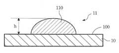
도 1a는 본 발명의 제1 실시형태에 따른 분석 스트립의 개략도이다.
도 1b는 도 1a의 선 AA를 따라 취한 분석 스트립의 단면도이다.
도 1c는 본 발명의 제1 실시형태의 다른 양태에 따른 분석 스트립의 개략도이다.
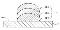
도 1d는 본 발명의 제1 실시형태의 다른 양태에 따른 분석 스트립의 개략도이다.
도 2는 본 발명의 제2 실시형태에 따른 분석 스트립의 제조 방법의 플로우 차트이다.
도 3a는 본 발명의 제3 실시형태에 따른 분석 스트립의 제조 방법의 플로우 차트이다.
도 3b는 본 발명의 제3 실시형태에 따른 제조 방법의 공정에서 분석 스트립의 개략도이다.1A is a schematic diagram of an analysis strip according to a first embodiment of the present invention.
FIG. 1B is a cross-sectional view of the analysis strip taken along line AA of FIG. 1A.
1C is a schematic diagram of an assay strip according to another aspect of the first embodiment of the present invention.
1D is a schematic diagram of an assay strip according to another aspect of the first embodiment of the present invention.
2 is a flow chart of a method for producing an assay strip according to a second embodiment of the present invention.
3A is a flow chart of a method for producing an assay strip according to a third embodiment of the present invention.
3B is a schematic diagram of an analysis strip in the process of the manufacturing method according to the third embodiment of the present invention.
바람직한 실시형태의 상세한 설명Detailed Description of the Preferred Embodiments
본 발명은 분석 스트립 및 그의 제조 방법을 제안하며, 본 발명에서 실시된 물리적 및 화학적 원리뿐만 아니라 용액 도포 수법은 당업자에게 공지된 것이므로 본 명세서에 더 이상 논의할 필요가 없다. 한편, 하기 상세한 설명에서 언급된 첨부한 도면은 예시적 목적으로 제공되며 실측으로 제조할 필요가 없다.The present invention proposes an analytical strip and a method of making the same, and the solution application techniques as well as the physical and chemical principles practiced herein are known to those skilled in the art and need not be discussed further herein. On the other hand, the accompanying drawings referred to in the following detailed description are provided for illustrative purposes and do not need to be fabricated by actual measurement.
본 발명의 제1 실시형태에 따른 분석 스트립에 대한 도 1a를 참조한다. 상기 분석 스트립(1)은 기판(10) 및 채널 구조(11)를 포함한다. 기판(10)은 평면(100)을 가지며, 채널(11)은 소정 패턴(12)에 따라서 기판(10)의 평면(100) 상에 형성된다. 채널(11)의 표면은 기판(10)의 평면(100)보다 낮지 않다. 또한, 상기 채널(11)은 중공-매트릭스 형태를 갖고 또 상기 채널(11)은 기판(10)의 평면(100)보다 더 친수성이다. 채널(11)을 제조하기 위하여, 고-친수성 용액을 리소그래픽 인쇄, 포토그라비아, 철판인쇄, 스크린-인쇄, 라인 마킹, 잉크젯/분무, 캐스팅, 또는 침지에 의해 기판(10)의 평면(100)에 도포한다.Reference is made to FIG. 1A for an analysis strip according to a first embodiment of the invention. The
기판(10)의 평면(100)에 도포된 용액은 니트로셀룰로오스 또는 유리섬유를 함유할 수 있으므로, 건조 및 고화된 후 채널(11)은 시험할 유체 샘플을 흡수하도록 다공성 중공-매트릭스 형태를 갖게 형성되어, 채널(11) 중의 유체 샘플 잔류량을 최소화한다. 또한, 유체 샘플이 채널(11)을 따라 통과할 때, 중공-매트릭스 형태는 유체 샘플 중의 공기 기포를 파괴하여 상기 기포들이 채널(11)을 막지 않게 한다. 또한, 본 발명의 분석 스트립(1)은 유체 샘플의 전기화학적 반응에 의해 생성된 전기적 신호를 검출하기 위하여, 기판(10)의 평면(100)과 채널(11) 사이에 배치된 한 쌍의 평면 전극(13)을 더 포함한다. 바람직하게는, 상기 기판(10)은 유연성이 있는 생체적합성 재료로 제조된다.Since the solution applied to the
도 1a의 AA선을 따라 취한 분석 스트립(1)의 단면도인 도 1b를 참조한다. 니트로셀룰로오스 용액을 건조 및 고화하는 공정 동안, 용액의 응집은 채널(11)이 그의 단면에서 평면(100)으로부터 융기되게 한다. 또한, 상기 채널(11)은 기판(10)의 평면(100) 상에 형성되므로, 채널 표면(110)과 기판(10)의 평면(100) 사이에 높이 차(h)가 존재한다. 다시 말해, 채널 표면(110)은 기판(10)의 평면(100)보다 낮지 않다.Reference is made to FIG. 1B, which is a cross-sectional view of the
또한, 채널(11)의 중공-매트릭스 형태는 그 조성이 유체 샘플 중의 시험될 물질과 연관되어 있는 반응 물질을 함유한다.In addition, the hollow-matrix form of the
채널(11)을 형성하기 위한 용액은 다음 기재와 같이 제조한다. 니트로셀룰로오스 분말을 에스테르 및 케톤을 함유하는 유기 용매와 혼합하여 혼합 용액을 형성한다. 다르게는, 상기 혼합 용액은 유리섬유를 특정 용매에 용해시키는 것에 의해 제조할 수 있다.The solution for forming the
상기 혼합 용액은 이어 기판(10)의 평면(100) 상에 소정 패턴으로 도포된다. 상기 용액이 건조된 후, 생성한 채널(11)은 유체 흡수성인 중공-매트릭스 형태를 갖는다. 따라서, 유체 샘플이 분석 스트립(1)에 도입될 때, 중공-매트릭스 형태를 갖는 채널(11)은 유체 샘플을 흡수하여 생화학적 또는 면역학적 반응이 실시되는 반응 영역(도시되지 않음)으로 전달할 수 있다.The mixed solution is then applied in a predetermined pattern on the
또한, 본 실시형태의 채널(11)은 전체적으로 중공-매트릭스 형태이고 또 상기 채널(11)의 각 부피 단위는 일정한 흡수성능을 가지므로, 채널(11)을 형성하는데 필요한 상기 혼합 용액의 부피는 흡착되어 분석될 유체 샘플의 소망하는 부피로부터 유도될 수 있다. 그 결과, 분석 스트립(1)의 유체 샘플의 소망하는 부피는 고정되어 설정되므로, 생성한 분석 스트립(1)은 소량 부피로 에세이하는데 적합하다.In addition, since the
상기 반응 물질은 바람직하게는 하기 기재한 바와 같이 채널(11)의 중공-매트릭스 형태에 형성된다. 기판(10)에 도포된 상기 혼합 용액이 건조 및 고화되어 채널(11)을 형성한 후, 상기 반응 물질을 함유하는 반응 용액이 채널(11)에 주입된 다음, 공기건조 또는 동결건조된다. 채널(11) 중에서 건조된 반응 물질은 분말 형태일 것이다.The reactant material is preferably formed in the hollow-matrix form of the
본 발명의 분석 스트립(1)은 생화학적 에세이 또는 면역학적 에세이에 적용될 수 있다. 생리학적 유체의 상이한 분석물을 검출하는 것은 상이한 에세이를 필요로 하고, 또 상이한 종류의 에세이는 상이한 종류의 반응물질을 필요로 하므로, 상이한 유형의 신호를 초래할 것이다. 예컨대, 생화학적 정량 에세이는 생물학적 유체 샘플 및 화학적 발광제에서 분석물의 효소 반응을 통하여 통상 실시되며, 이는 적합한 효소에 의해 촉매작용을 받아 검출을 위한 특정 파장을 갖는 광학 신호를 생성한다. 따라서, 분석 스트립(1)의 반응 물질은, 생화학적 정량 에세이에 적용될 때, 주로 효소 및 상응하는 화학적 시약을 포함할 것이다. 한편, α-태아단백질과 같은 생리학적 유체 샘플에서 특정 단백질을 정량 검출하는 구상일 때, 이러한 분석 에세이는 보통 표적 단백질을 특이적으로 인식할 수 있는 항체 및 기타 상응하는 화학적 시약을 이용하여 검출가능한 신호를 생성한다. 따라서, 분석 스트립(1)의 반응 물질은, 정량 면역분석에 적용될 때, 주로 항체 및 상응하는 시약을 포함할 것이다. 따라서, 본 발명의 분석 스트립(1)은 다양한 유형의 생리학적 유체 시편(예컨대, 요 또는 혈액)에서 다양한 분석물을 정량 검출하는데 적합하다.The
도 1c는 본 발명에 개시된 분석 스트립의 다른 양태를 도시한다. 채널(11)은 적어도 1개의 분기 채널(111) 및 연장된 영역(112)을 더 포함할 수 있으므로 상이한 유체(시험될 유체 샘플 및 반응에 필요한 시약과 같은)가 상이한 분기 채널(111)을 따라 흘러서 연장된 영역(112)에서 완전히 혼합된다. 상기 연장된 영역(112)은 반응물질과 반응하는 채널에서 유체 샘플에 대해 충분한 반응 시간을 제공하여, 에세이의 결과의 정확성을 개선하기 위하여 돔형, 직사각형 또는 섬모양으로 형성될 수 있다.1C illustrates another embodiment of an assay strip disclosed herein. The
도 1d에 도시된 바와 같이, 기판(10)의 평면(100)은 스택된 채널(113)을 더 포함할 수 있다. 스택된 채널(113)은 제1 채널(1131), 제2 채널(1132), 및 제3 채널(1133)을 포함한다. 스택된 채널(113)에서, 채널은 실시될 에세이 및 시험될 유체 샘플의 유형에 따라서 동일하거나 상이한 채널 패턴일 수 있다.As shown in FIG. 1D, the
상술한 제1 실시형태의 분석 스트립 이외에, 본 발명은 제2 및 제3의 바람직한 실시형태로서 이하에 기재한 바와 같은 분석 스트립의 제조 방법을 또한 제공한다.In addition to the assay strip of the first embodiment described above, the present invention also provides a method for producing the assay strip as described below as the second and third preferred embodiments.
본 발명의 제2 실시형태에 따른 분석 스트립을 제조하는 방법의 플로우 차트인 도 2를 참조한다. 본 실시형태에서 언급된 분석 스트립은 제1 실시형태의 분석 스트립과 동일한 구조적 특징을 가지며, 도 1a 내지 도 1c에 도시된 것과 동일한 번호는 반복적인 설명없이 여기서도 사용된다.Reference is made to FIG. 2, which is a flow chart of a method of making an assay strip according to a second embodiment of the present invention. The assay strip mentioned in this embodiment has the same structural features as the assay strip of the first embodiment, and the same numbers as shown in Figs. 1A to 1C are used here without repetitive description.
본 실시형태의 분석 스트립의 제조 방법은 주로 다음 단계를 포함한다:The method for producing an assay strip of this embodiment mainly includes the following steps:
단계 21: 먼저 평면(100)을 갖는 기판(1)을 제공한다;Step 21: first provide a
단계 22: 상기 평면(100) 상에 소정 패턴(12)에 따라 용액을 도포한다; 및Step 22: applying a solution according to a
단계 23: 도포된 용액을 건조시켜 소정 패턴(12)을 갖는 채널(11)을 형성한다. 건조된 채널 구조(11)의 표면과 기판(10) 사이에는 높이 차(h)가 존재하며, 상기 용액은 리소그래픽 인쇄, 포토그라비아, 철판인쇄, 스크린 인쇄, 라인 마킹 또는 잉크젯/분무에 의해 도포될 수 있다.Step 23: The applied solution is dried to form a
본 발명의 제3의 바람직한 실시형태는 분석 스트립을 제조하는 다른 방법에 관한 것이다. 도 3a 및 도 3b를 참조한다. 도 3a는 본 발명의 제3 실시형태의 제조 방법의 플로우 차트이다. 도 3b는 본 실시형태의 제조 방법의 공정에서 분석 스트립을 도시한다.A third preferred embodiment of the invention relates to another method of making an assay strip. See FIGS. 3A and 3B. It is a flowchart of the manufacturing method of 3rd embodiment of this invention. 3B shows an analysis strip in the process of the manufacturing method of the present embodiment.
본 실시형태의 분석 스트립의 제조 방법은 주로 다음 단계를 포함한다:The method for producing an assay strip of this embodiment mainly includes the following steps:
단계 31: 먼저 평면(300)을 갖는 기판(30)을 제공한다.Step 31: First, provide a
단계 32: 소정 패턴(32)으로 음각된 마스크(33)를 제공한다.Step 32: Provide a
단계 33: 상기 마스크(33)를 탈착가능하게 기판(30)에 접착시킨다.Step 33: Removably attach the
단계 34: 용액을 제공하고 또 소정 패턴(32)으로 음각된 곳에 상기 용액을 충전한다.Step 34: Provide a solution and fill the solution in the
단계 35: 소정 패턴(32)에 충전된 용액을 건조시킨다.Step 35: The solution filled in the
단계 36: 마스크(33)를 제거하여 소정 패턴(32)을 갖는 채널(31)을 형성한다. 건조된 채널(31)의 표면은 기판(30)의 평면(300)보다 낮지 않고, 상기 채널(31)은 중공-매트릭스 형태를 갖는다. 또한, 상기 채널(31)은 기판(30)의 평면(300)보다 더 친수성이다.Step 36: Remove the
단계 37: 반응 물질을 제공하고 채널(31)의 중공-매트릭스 형태에 상기 반응 물질을 혼입시킨다.Step 37: Provide the reactant and incorporate the reactant in the hollow-matrix form of the
본 실시형태에서, 채널(31)의 형성, 용액의 조성 및 중공-매트릭스 형태에 반응 물질을 혼입하는 방식은 상기 제1 실시형태에 기재된 것과 유사하므로 여기서 생략한다.In the present embodiment, the formation of the
본 발명은 바람직한 실시형태를 참조하며 기재하며 또 이러한 실시형태는 본 발명의 범위를 제한하지 않음을 이해해야 한다. 또한, 본 명세서에 기재된 내용은 당업자가 용이하게 이해할 수 있고 당업자들이 실시할 수 있는 것이며, 본 발명의 개념에서 벗어나지 않는 모든 등가의 변화 또는 변형은 첨부된 특허청구범위에 포함되어야 한다.It is to be understood that the invention refers to and describes preferred embodiments and that such embodiments do not limit the scope of the invention. In addition, the contents described herein are easily understood by those skilled in the art and can be implemented by those skilled in the art, and all equivalent changes or modifications without departing from the concept of the present invention should be included in the appended claims.
1: 분석 스트립
10: 기판
11: 채널
100: 평면1: analysis strip
10: Substrate
11: channel
100: flat
Claims (45)
Translated fromKorean상기 기판은 평면을 갖고,
상기 채널은 채널의 표면이 상기 기판의 평면보다 낮지 않고, 채널이 중공-매트릭스 형태를 가지며, 채널이 상기 기판의 평면보다 더 친수성이 되게 하는 방식으로 소정 패턴에 따라 상기 평면 상에 형성되며,
반응 물질이 상기 중공 매트릭스 형태에 혼입되어 있는 것을 특징으로 하는, 분석 스트립.An analysis strip comprising a substrate and a channel,
The substrate has a plane,
The channel is formed on the plane according to a predetermined pattern in such a manner that the surface of the channel is not lower than the plane of the substrate, the channel has a hollow-matrix form, and the channel is more hydrophilic than the plane of the substrate,
An assay strip, characterized in that a reactant is incorporated in the hollow matrix form.
상기 평면 상에 소정 패턴에 따라 용액을 도포하며;
상기 도포된 용액을 건조시켜, 채널의 표면이 상기 평면보다 낮지 않고, 채널이 중공-매트릭스 형태를 가지며, 채널이 상기 기판의 평면보다 더 친수성이 되게 하는 방식으로 소정 패턴의 채널을 형성하고;
반응 물질을 제공하여 상기 중공-매트릭스 형태에 혼입시키는 것을 포함하는, 분석 스트립의 제조 방법.Providing a substrate having a plane;
Applying a solution according to a predetermined pattern on the plane;
Drying the applied solution to form a channel of a predetermined pattern in such a manner that the surface of the channel is not lower than the plane, the channel has a hollow-matrix form, and the channel is more hydrophilic than the plane of the substrate;
Providing a reactant and incorporating it into said hollow-matrix form.
소정 패턴으로 음각된 마스크를 제공하며;
상기 마스크를 탈착가능하게 상기 기판에 접착시키고;
소정 패턴으로 음각된 곳에 용액을 도포하며;
상기 도포된 용액을 건조시키고;
상기 마스크를 제거하여, 채널의 표면이 상기 기판의 평면보다 낮지 않고, 채널이 중공-매트릭스 형태를 가지며, 채널이 상기 기판의 평면보다 더 친수성이 되게 하는 방식으로 소정 패턴을 갖는 채널을 형성하며; 및
반응 물질을 제공하여 상기 반응 물질이 중공-매트릭스 형태에 혼입되게 하는 것을 포함하는, 분석 스트립의 제조 방법.Providing a substrate having a plane;
Providing a mask engraved in a predetermined pattern;
Detachably attaching the mask to the substrate;
Applying the solution in a recess in a predetermined pattern;
Drying the applied solution;
Removing the mask to form a channel having a predetermined pattern in such a manner that the surface of the channel is not lower than the plane of the substrate, the channel has a hollow-matrix shape, and the channel is more hydrophilic than the plane of the substrate; And
Providing a reactant such that the reactant is incorporated into the hollow-matrix form.
Applications Claiming Priority (1)
| Application Number | Priority Date | Filing Date | Title |
|---|---|---|---|
| PCT/CN2009/070941WO2010108310A1 (en) | 2009-03-23 | 2009-03-23 | Fluid test chip and method to make it |
Publications (2)
| Publication Number | Publication Date |
|---|---|
| KR20110129411Atrue KR20110129411A (en) | 2011-12-01 |
| KR101329846B1 KR101329846B1 (en) | 2013-11-14 |
Family
ID=42738001
Family Applications (1)
| Application Number | Title | Priority Date | Filing Date |
|---|---|---|---|
| KR1020117022002AExpired - Fee RelatedKR101329846B1 (en) | 2009-03-23 | 2009-03-23 | Analytical strip and the manufacturing method thereof |
Country Status (10)
| Country | Link |
|---|---|
| US (1) | US8367015B2 (en) |
| EP (1) | EP2413141A4 (en) |
| JP (1) | JP2012521543A (en) |
| KR (1) | KR101329846B1 (en) |
| CN (1) | CN102395884A (en) |
| AU (1) | AU2009342863B2 (en) |
| BR (1) | BRPI0925015A2 (en) |
| CA (1) | CA2755347A1 (en) |
| RU (1) | RU2011141298A (en) |
| WO (1) | WO2010108310A1 (en) |
Cited By (1)
| Publication number | Priority date | Publication date | Assignee | Title |
|---|---|---|---|---|
| KR20190089495A (en)* | 2018-01-23 | 2019-07-31 | 윤형열 | Pattern forming device and method |
Families Citing this family (2)
| Publication number | Priority date | Publication date | Assignee | Title |
|---|---|---|---|---|
| JP5610389B2 (en)* | 2010-11-05 | 2014-10-22 | 国立大学法人北陸先端科学技術大学院大学 | Immunochromatographic analysis strip and immunochromatographic analysis method |
| CN109738428B (en)* | 2019-02-28 | 2021-08-10 | 杭州艾克瑞尔检测科技有限公司 | Chromogenic titration detection device and detection method for formaldehyde content in air |
Family Cites Families (50)
| Publication number | Priority date | Publication date | Assignee | Title |
|---|---|---|---|---|
| FR2584498B1 (en)* | 1985-07-02 | 1987-10-16 | Centre Nat Rech Scient | DEVICE FOR DETECTING ON A NITROCELLULOSE SHEET THE PRESENCE OF MACROMOLECULAR COMPLEXES, SUCH AS ANTIGENS / ANTIBODIES AND METHOD FOR IMPLEMENTING SAME. |
| WO1990008322A1 (en) | 1989-01-11 | 1990-07-26 | Nathan, Pamela, Anne | An immunological method of testing concentration |
| US5540888A (en)* | 1991-11-11 | 1996-07-30 | British Technology Group Limited | Liquid transfer assay devices |
| US5290518A (en)* | 1992-08-17 | 1994-03-01 | Eastman Kodak Company | Flexible extraction device with burstable sidewall |
| US5547833A (en) | 1994-01-04 | 1996-08-20 | Intracel Corporation | Radial flow assay, delivering member, test kit, and methods |
| GB9416002D0 (en)* | 1994-08-08 | 1994-09-28 | Univ Cranfield | Fluid transport device |
| US5569608A (en) | 1995-01-30 | 1996-10-29 | Bayer Corporation | Quantitative detection of analytes on immunochromatographic strips |
| US5837584A (en)* | 1997-01-15 | 1998-11-17 | Macronix International Co., Ltd. | Virtual ground flash cell with asymmetrically placed source and drain and method of fabrication |
| GB9705667D0 (en)* | 1997-03-19 | 1997-05-07 | Jackson James R | Diagnostic and analytical devices |
| KR100241928B1 (en)* | 1997-03-31 | 2000-03-02 | 박종근 | Determination device in which the electrode is integrally formed on the porous thin film and the quantification method using the same |
| US6756019B1 (en)* | 1998-02-24 | 2004-06-29 | Caliper Technologies Corp. | Microfluidic devices and systems incorporating cover layers |
| CA2339599A1 (en)* | 1998-08-06 | 2000-02-17 | Spectral Diagnostics, Inc. | Analytical test device and method |
| AUPP713498A0 (en) | 1998-11-17 | 1998-12-10 | Chandler, Howard Milne | A method of detecting blood |
| EP1141713A1 (en) | 1999-01-09 | 2001-10-10 | Bernd Dr. Pevec | Method and device for determining an analyte |
| CN1304041A (en)* | 1999-10-25 | 2001-07-18 | 上海市工业微生物研究所 | Test strip for blood-sugar and its preparation method |
| WO2001038873A2 (en)* | 1999-11-24 | 2001-05-31 | Biotronic Technologies, Inc. | Devices and methods for detecting analytes using electrosensor having capture reagent |
| JP2001201479A (en) | 2000-01-21 | 2001-07-27 | Matsushita Electric Ind Co Ltd | Biosensor |
| US6436722B1 (en) | 2000-04-18 | 2002-08-20 | Idexx Laboratories, Inc. | Device and method for integrated diagnostics with multiple independent flow paths |
| EP1291650B1 (en) | 2000-05-16 | 2014-04-02 | ARKRAY, Inc. | Biosensor and method for manufacturing the same |
| US6627159B1 (en)* | 2000-06-28 | 2003-09-30 | 3M Innovative Properties Company | Centrifugal filling of sample processing devices |
| US6984494B2 (en) | 2000-08-15 | 2006-01-10 | Genentech, Inc. | Analytical method |
| US6884592B2 (en) | 2001-09-05 | 2005-04-26 | Lifescan, Inc. | Devices for analyte concentration determination and methods of manufacturing and using the same |
| GB0128350D0 (en)* | 2001-11-27 | 2002-01-16 | Lab901 Ltd | Non-rigid apparatus for microfluidic applications |
| FI118904B (en) | 2003-03-28 | 2008-04-30 | Ani Biotech Oy | Multi-channel test equipment, method of preparation thereof and its use |
| WO2005075979A1 (en)* | 2004-02-04 | 2005-08-18 | Matsushita Electric Industrial Co., Ltd. | Biosensor and biosensor measuring device and method |
| AU2005231107B8 (en) | 2004-03-30 | 2011-04-14 | Global Life Sciences Solutions Usa Llc | Lateral flow format, materials and methods |
| DE102004039628A1 (en)* | 2004-08-10 | 2006-02-23 | NMI Naturwissenschaftliches und Medizinisches Institut an der Universität Tübingen | Support plate for carrying out functional tests on biological cells and method for coating the support plate |
| KR100579831B1 (en)* | 2004-09-07 | 2006-05-15 | 삼성전자주식회사 | Assemble Microfluidic Biosample Processing System |
| EP1815250A4 (en) | 2004-11-01 | 2008-06-25 | Internat Bio Therapeutic Res I | IMMUNODIAGNOSTIC ONE-WAY TEST SYSTEM |
| KR100635110B1 (en)* | 2004-12-09 | 2006-10-17 | 주식회사 바이오디지트 | Lab Detectors for Field Analysis and Signal Detectors for Lab-on-A-Chips |
| CN100504373C (en) | 2005-04-20 | 2009-06-24 | 华广生技股份有限公司 | Electrochemical sensory test strip and its manufacturing method |
| CN1851459A (en) | 2005-04-22 | 2006-10-25 | 清华大学 | Multi-parameter whole blood integrating test bar |
| SE0501418L (en)* | 2005-06-20 | 2006-09-26 | Aamic Ab | Method and means for effecting liquid transport |
| US7883665B2 (en)* | 2005-09-14 | 2011-02-08 | Alcatel-Lucent Usa Inc. | Chemical and biological detection arrays |
| US7723120B2 (en)* | 2005-10-26 | 2010-05-25 | General Electric Company | Optical sensor array system and method for parallel processing of chemical and biochemical information |
| JP2007139649A (en) | 2005-11-21 | 2007-06-07 | Asahi Kasei Corp | Analytical porous material |
| WO2007081330A1 (en) | 2006-01-10 | 2007-07-19 | Inverness Medical Switzerland Gmbh | Device and method for immunoassays |
| CN100501510C (en)* | 2006-02-15 | 2009-06-17 | 虹创科技股份有限公司 | Substrate structure and manufacturing method of thin film pattern layer |
| CN100388906C (en) | 2006-03-22 | 2008-05-21 | 山东师范大学 | Measuring instrument and measuring method for dynamic position of center of gravity of human body |
| TWI310786B (en) | 2006-04-10 | 2009-06-11 | Univ Nat Sun Yat Sen | Method for sorting microfluidic particles and microfluidic chips therefor |
| CN101421620B (en) | 2006-05-08 | 2013-09-18 | 八新思生物技术有限公司 | Method for the coupled enzyme immunochemical assay of analytes by means of endogenous calibrators |
| DE102007003830B4 (en)* | 2007-01-25 | 2009-08-06 | Robert Seuffer Gmbh & Co. Kg | Device for measuring an electrical current flowing through an electrical conductor |
| TW200834073A (en)* | 2007-02-14 | 2008-08-16 | Chung-Cheng Chang | A nucleic acid hybridization method |
| JP4850855B2 (en)* | 2007-03-22 | 2012-01-11 | 信越化学工業株式会社 | Manufacturing method of substrate for producing microarray |
| CN101303358A (en) | 2007-05-10 | 2008-11-12 | 胡军 | Siphoning type blood sugar test paper |
| US20110318822A1 (en)* | 2008-08-29 | 2011-12-29 | Chih-Wei Hsieh | Analytical strip |
| TWM354070U (en) | 2008-09-19 | 2009-04-01 | Actherm Inc | Substrate |
| TWM350706U (en) | 2008-09-23 | 2009-02-11 | Actherm Inc | Testing strip |
| TWM359693U (en) | 2008-10-09 | 2009-06-21 | Actherm Inc | Combinatory testing strip |
| TW201035551A (en)* | 2009-03-27 | 2010-10-01 | Actherm Inc | Analytical strip and the manufacturing method thereof |
- 2009
- 2009-03-23RURU2011141298/15Apatent/RU2011141298A/ennot_activeApplication Discontinuation
- 2009-03-23CACA2755347Apatent/CA2755347A1/ennot_activeAbandoned
- 2009-03-23CNCN2009801582327Apatent/CN102395884A/enactivePending
- 2009-03-23WOPCT/CN2009/070941patent/WO2010108310A1/enactiveApplication Filing
- 2009-03-23BRBRPI0925015Apatent/BRPI0925015A2/ennot_activeIP Right Cessation
- 2009-03-23JPJP2012501106Apatent/JP2012521543A/enactivePending
- 2009-03-23AUAU2009342863Apatent/AU2009342863B2/ennot_activeCeased
- 2009-03-23KRKR1020117022002Apatent/KR101329846B1/ennot_activeExpired - Fee Related
- 2009-03-23EPEP09842047Apatent/EP2413141A4/ennot_activeWithdrawn
- 2010
- 2010-04-16USUS12/762,165patent/US8367015B2/ennot_activeExpired - Fee Related
Cited By (1)
| Publication number | Priority date | Publication date | Assignee | Title |
|---|---|---|---|---|
| KR20190089495A (en)* | 2018-01-23 | 2019-07-31 | 윤형열 | Pattern forming device and method |
Also Published As
| Publication number | Publication date |
|---|---|
| AU2009342863A1 (en) | 2011-09-29 |
| EP2413141A1 (en) | 2012-02-01 |
| US8367015B2 (en) | 2013-02-05 |
| JP2012521543A (en) | 2012-09-13 |
| EP2413141A4 (en) | 2013-03-06 |
| CN102395884A (en) | 2012-03-28 |
| RU2011141298A (en) | 2013-04-27 |
| CA2755347A1 (en) | 2010-09-30 |
| AU2009342863B2 (en) | 2013-09-05 |
| KR101329846B1 (en) | 2013-11-14 |
| WO2010108310A1 (en) | 2010-09-30 |
| BRPI0925015A2 (en) | 2018-02-27 |
| US20100240120A1 (en) | 2010-09-23 |
Similar Documents
| Publication | Publication Date | Title |
|---|---|---|
| EP2646152B1 (en) | Sample metering device and assay device with integrated sample dilution | |
| EP1203959A1 (en) | Analyzing cartridge and liquid feed control device | |
| WO2012075256A2 (en) | Sample metering device and assay device with integrated sample dilution | |
| US9778251B2 (en) | Ratiometric immunoassay method and blood testing device | |
| EP2336776B1 (en) | Liquid test strip | |
| KR101329846B1 (en) | Analytical strip and the manufacturing method thereof | |
| JP5243609B2 (en) | Combination test strip | |
| JP5162031B2 (en) | Liquid inspection method | |
| TWI402500B (en) | Testing strip | |
| KR101258339B1 (en) | Substrate of analytical strip | |
| NZ591392A (en) | Two uses fluid test chip |
Legal Events
| Date | Code | Title | Description |
|---|---|---|---|
| A201 | Request for examination | ||
| E13-X000 | Pre-grant limitation requested | St.27 status event code:A-2-3-E10-E13-lim-X000 | |
| P11-X000 | Amendment of application requested | St.27 status event code:A-2-2-P10-P11-nap-X000 | |
| P13-X000 | Application amended | St.27 status event code:A-2-2-P10-P13-nap-X000 | |
| PA0105 | International application | St.27 status event code:A-0-1-A10-A15-nap-PA0105 | |
| PA0201 | Request for examination | St.27 status event code:A-1-2-D10-D11-exm-PA0201 | |
| P11-X000 | Amendment of application requested | St.27 status event code:A-2-2-P10-P11-nap-X000 | |
| P13-X000 | Application amended | St.27 status event code:A-2-2-P10-P13-nap-X000 | |
| PG1501 | Laying open of application | St.27 status event code:A-1-1-Q10-Q12-nap-PG1501 | |
| E902 | Notification of reason for refusal | ||
| PE0902 | Notice of grounds for rejection | St.27 status event code:A-1-2-D10-D21-exm-PE0902 | |
| P11-X000 | Amendment of application requested | St.27 status event code:A-2-2-P10-P11-nap-X000 | |
| P13-X000 | Application amended | St.27 status event code:A-2-2-P10-P13-nap-X000 | |
| E701 | Decision to grant or registration of patent right | ||
| PE0701 | Decision of registration | St.27 status event code:A-1-2-D10-D22-exm-PE0701 | |
| GRNT | Written decision to grant | ||
| PR0701 | Registration of establishment | St.27 status event code:A-2-4-F10-F11-exm-PR0701 | |
| PR1002 | Payment of registration fee | St.27 status event code:A-2-2-U10-U12-oth-PR1002 Fee payment year number:1 | |
| PG1601 | Publication of registration | St.27 status event code:A-4-4-Q10-Q13-nap-PG1601 | |
| LAPS | Lapse due to unpaid annual fee | ||
| PC1903 | Unpaid annual fee | St.27 status event code:A-4-4-U10-U13-oth-PC1903 Not in force date:20161109 Payment event data comment text:Termination Category : DEFAULT_OF_REGISTRATION_FEE | |
| PC1903 | Unpaid annual fee | St.27 status event code:N-4-6-H10-H13-oth-PC1903 Ip right cessation event data comment text:Termination Category : DEFAULT_OF_REGISTRATION_FEE Not in force date:20161109 |