KR20110127717A - Patient-Specific Surgical Guide Locators and Mounts - Google Patents
Patient-Specific Surgical Guide Locators and MountsDownload PDFInfo
- Publication number
- KR20110127717A KR20110127717AKR1020117022349AKR20117022349AKR20110127717AKR 20110127717 AKR20110127717 AKR 20110127717AKR 1020117022349 AKR1020117022349 AKR 1020117022349AKR 20117022349 AKR20117022349 AKR 20117022349AKR 20110127717 AKR20110127717 AKR 20110127717A
- Authority
- KR
- South Korea
- Prior art keywords
- bone
- ablation guide
- ablation
- complementary
- locator
- Prior art date
- Legal status (The legal status is an assumption and is not a legal conclusion. Google has not performed a legal analysis and makes no representation as to the accuracy of the status listed.)
- Granted
Links
Images


Classifications
- A—HUMAN NECESSITIES
- A61—MEDICAL OR VETERINARY SCIENCE; HYGIENE
- A61B—DIAGNOSIS; SURGERY; IDENTIFICATION
- A61B17/00—Surgical instruments, devices or methods
- A61B17/14—Surgical saws
- A61B17/15—Guides therefor
- A61B17/154—Guides therefor for preparing bone for knee prosthesis
- A61B17/155—Cutting femur
- A—HUMAN NECESSITIES
- A61—MEDICAL OR VETERINARY SCIENCE; HYGIENE
- A61B—DIAGNOSIS; SURGERY; IDENTIFICATION
- A61B17/00—Surgical instruments, devices or methods
- A61B17/14—Surgical saws
- A61B17/15—Guides therefor
- A—HUMAN NECESSITIES
- A61—MEDICAL OR VETERINARY SCIENCE; HYGIENE
- A61B—DIAGNOSIS; SURGERY; IDENTIFICATION
- A61B17/00—Surgical instruments, devices or methods
- A61B17/14—Surgical saws
- A61B17/15—Guides therefor
- A61B17/151—Guides therefor for corrective osteotomy
- A—HUMAN NECESSITIES
- A61—MEDICAL OR VETERINARY SCIENCE; HYGIENE
- A61B—DIAGNOSIS; SURGERY; IDENTIFICATION
- A61B17/00—Surgical instruments, devices or methods
- A61B17/14—Surgical saws
- A61B17/15—Guides therefor
- A61B17/154—Guides therefor for preparing bone for knee prosthesis
- A—HUMAN NECESSITIES
- A61—MEDICAL OR VETERINARY SCIENCE; HYGIENE
- A61B—DIAGNOSIS; SURGERY; IDENTIFICATION
- A61B17/00—Surgical instruments, devices or methods
- A61B17/14—Surgical saws
- A61B17/15—Guides therefor
- A61B17/154—Guides therefor for preparing bone for knee prosthesis
- A61B17/157—Cutting tibia
- A—HUMAN NECESSITIES
- A61—MEDICAL OR VETERINARY SCIENCE; HYGIENE
- A61B—DIAGNOSIS; SURGERY; IDENTIFICATION
- A61B17/00—Surgical instruments, devices or methods
- A61B17/16—Instruments for performing osteoclasis; Drills or chisels for bones; Trepans
- A61B17/17—Guides or aligning means for drills, mills, pins or wires
- A61B17/1739—Guides or aligning means for drills, mills, pins or wires specially adapted for particular parts of the body
- A61B17/1775—Guides or aligning means for drills, mills, pins or wires specially adapted for particular parts of the body for the foot or ankle
- A—HUMAN NECESSITIES
- A61—MEDICAL OR VETERINARY SCIENCE; HYGIENE
- A61B—DIAGNOSIS; SURGERY; IDENTIFICATION
- A61B34/00—Computer-aided surgery; Manipulators or robots specially adapted for use in surgery
- A61B34/10—Computer-aided planning, simulation or modelling of surgical operations
- B—PERFORMING OPERATIONS; TRANSPORTING
- B29—WORKING OF PLASTICS; WORKING OF SUBSTANCES IN A PLASTIC STATE IN GENERAL
- B29C—SHAPING OR JOINING OF PLASTICS; SHAPING OF MATERIAL IN A PLASTIC STATE, NOT OTHERWISE PROVIDED FOR; AFTER-TREATMENT OF THE SHAPED PRODUCTS, e.g. REPAIRING
- B29C64/00—Additive manufacturing, i.e. manufacturing of three-dimensional [3D] objects by additive deposition, additive agglomeration or additive layering, e.g. by 3D printing, stereolithography or selective laser sintering
- B29C64/30—Auxiliary operations or equipment
- B29C64/386—Data acquisition or data processing for additive manufacturing
- G—PHYSICS
- G05—CONTROLLING; REGULATING
- G05B—CONTROL OR REGULATING SYSTEMS IN GENERAL; FUNCTIONAL ELEMENTS OF SUCH SYSTEMS; MONITORING OR TESTING ARRANGEMENTS FOR SUCH SYSTEMS OR ELEMENTS
- G05B15/00—Systems controlled by a computer
- G05B15/02—Systems controlled by a computer electric
- G—PHYSICS
- G06—COMPUTING OR CALCULATING; COUNTING
- G06F—ELECTRIC DIGITAL DATA PROCESSING
- G06F30/00—Computer-aided design [CAD]
- A—HUMAN NECESSITIES
- A61—MEDICAL OR VETERINARY SCIENCE; HYGIENE
- A61B—DIAGNOSIS; SURGERY; IDENTIFICATION
- A61B17/00—Surgical instruments, devices or methods
- A61B2017/0023—Surgical instruments, devices or methods disposable
- A—HUMAN NECESSITIES
- A61—MEDICAL OR VETERINARY SCIENCE; HYGIENE
- A61B—DIAGNOSIS; SURGERY; IDENTIFICATION
- A61B17/00—Surgical instruments, devices or methods
- A61B2017/00526—Methods of manufacturing
- A—HUMAN NECESSITIES
- A61—MEDICAL OR VETERINARY SCIENCE; HYGIENE
- A61B—DIAGNOSIS; SURGERY; IDENTIFICATION
- A61B17/00—Surgical instruments, devices or methods
- A61B17/56—Surgical instruments or methods for treatment of bones or joints; Devices specially adapted therefor
- A61B2017/568—Surgical instruments or methods for treatment of bones or joints; Devices specially adapted therefor produced with shape and dimensions specific for an individual patient
- A—HUMAN NECESSITIES
- A61—MEDICAL OR VETERINARY SCIENCE; HYGIENE
- A61B—DIAGNOSIS; SURGERY; IDENTIFICATION
- A61B34/00—Computer-aided surgery; Manipulators or robots specially adapted for use in surgery
- A61B34/10—Computer-aided planning, simulation or modelling of surgical operations
- A61B2034/101—Computer-aided simulation of surgical operations
- A61B2034/102—Modelling of surgical devices, implants or prosthesis
- A61B2034/104—Modelling the effect of the tool, e.g. the effect of an implanted prosthesis or for predicting the effect of ablation or burring
- A—HUMAN NECESSITIES
- A61—MEDICAL OR VETERINARY SCIENCE; HYGIENE
- A61B—DIAGNOSIS; SURGERY; IDENTIFICATION
- A61B34/00—Computer-aided surgery; Manipulators or robots specially adapted for use in surgery
- A61B34/10—Computer-aided planning, simulation or modelling of surgical operations
- A61B2034/108—Computer aided selection or customisation of medical implants or cutting guides
- B—PERFORMING OPERATIONS; TRANSPORTING
- B33—ADDITIVE MANUFACTURING TECHNOLOGY
- B33Y—ADDITIVE MANUFACTURING, i.e. MANUFACTURING OF THREE-DIMENSIONAL [3-D] OBJECTS BY ADDITIVE DEPOSITION, ADDITIVE AGGLOMERATION OR ADDITIVE LAYERING, e.g. BY 3-D PRINTING, STEREOLITHOGRAPHY OR SELECTIVE LASER SINTERING
- B33Y50/00—Data acquisition or data processing for additive manufacturing
- B33Y50/02—Data acquisition or data processing for additive manufacturing for controlling or regulating additive manufacturing processes
- B—PERFORMING OPERATIONS; TRANSPORTING
- B33—ADDITIVE MANUFACTURING TECHNOLOGY
- B33Y—ADDITIVE MANUFACTURING, i.e. MANUFACTURING OF THREE-DIMENSIONAL [3-D] OBJECTS BY ADDITIVE DEPOSITION, ADDITIVE AGGLOMERATION OR ADDITIVE LAYERING, e.g. BY 3-D PRINTING, STEREOLITHOGRAPHY OR SELECTIVE LASER SINTERING
- B33Y70/00—Materials specially adapted for additive manufacturing
- B—PERFORMING OPERATIONS; TRANSPORTING
- B33—ADDITIVE MANUFACTURING TECHNOLOGY
- B33Y—ADDITIVE MANUFACTURING, i.e. MANUFACTURING OF THREE-DIMENSIONAL [3-D] OBJECTS BY ADDITIVE DEPOSITION, ADDITIVE AGGLOMERATION OR ADDITIVE LAYERING, e.g. BY 3-D PRINTING, STEREOLITHOGRAPHY OR SELECTIVE LASER SINTERING
- B33Y80/00—Products made by additive manufacturing
- Y—GENERAL TAGGING OF NEW TECHNOLOGICAL DEVELOPMENTS; GENERAL TAGGING OF CROSS-SECTIONAL TECHNOLOGIES SPANNING OVER SEVERAL SECTIONS OF THE IPC; TECHNICAL SUBJECTS COVERED BY FORMER USPC CROSS-REFERENCE ART COLLECTIONS [XRACs] AND DIGESTS
- Y10—TECHNICAL SUBJECTS COVERED BY FORMER USPC
- Y10T—TECHNICAL SUBJECTS COVERED BY FORMER US CLASSIFICATION
- Y10T29/00—Metal working
- Y10T29/49—Method of mechanical manufacture
- Y10T29/49826—Assembling or joining
- Y10T29/49863—Assembling or joining with prestressing of part
Landscapes
- Health & Medical Sciences (AREA)
- Surgery (AREA)
- Life Sciences & Earth Sciences (AREA)
- Engineering & Computer Science (AREA)
- Medical Informatics (AREA)
- Animal Behavior & Ethology (AREA)
- Nuclear Medicine, Radiotherapy & Molecular Imaging (AREA)
- Veterinary Medicine (AREA)
- Public Health (AREA)
- General Health & Medical Sciences (AREA)
- Biomedical Technology (AREA)
- Heart & Thoracic Surgery (AREA)
- Molecular Biology (AREA)
- Oral & Maxillofacial Surgery (AREA)
- Dentistry (AREA)
- Orthopedic Medicine & Surgery (AREA)
- Physical Education & Sports Medicine (AREA)
- Transplantation (AREA)
- Physics & Mathematics (AREA)
- Robotics (AREA)
- Materials Engineering (AREA)
- Chemical & Material Sciences (AREA)
- General Engineering & Computer Science (AREA)
- General Physics & Mathematics (AREA)
- Theoretical Computer Science (AREA)
- Automation & Control Theory (AREA)
- Mechanical Engineering (AREA)
- Manufacturing & Machinery (AREA)
- Optics & Photonics (AREA)
- Geometry (AREA)
- Evolutionary Computation (AREA)
- Computer Hardware Design (AREA)
- Surgical Instruments (AREA)
- Architecture (AREA)
- Software Systems (AREA)
- Prostheses (AREA)
Abstract
Translated fromKoreanDescription
Translated fromKorean본 출원은 2009년 2월 24일자로 출원하고, 발명의 명칭이 특정 수술용 가이드 마운트인, 미국 가출원 제61/154,845호의 이익을 주장한다.This application filed on Feb. 24, 2009, claims the benefit of US Provisional Application No. 61 / 154,845, entitled Specific Surgical Guide Mounts.
본 발명은 일반적으로 수술용 가이드, 및 슬관절 전치환술, 고관절 치환술, 또는 발목관절 치환술과 같은 정형외과 수술 동안에 환자 몸에 관련하여 이러한 가이드를 위치시키는데 사용되는 고정 장치, 및 이러한 로케이터 기구를 설계하고 사용하기 위한 방법에 관한 것이다.The present invention generally designs and uses surgical guides, and fixation devices used to position such guides with respect to the patient's body during orthopedic surgery, such as total knee arthroplasty, hip replacement, or ankle replacement, and such locator instruments. It relates to a method for doing so.
관절(무릎, 엉덩이 및 발목) 전치환술 보철물은 공지되어 있다. 많은 경우에, 이러한 보철물을 수용하기 위하여, 특별하게 설계된 지그 또는 고정 장치는 외과의사가 대퇴골, 경골, 또는 둘 모두를 정밀하고 정확하게 절제하는 것을 가능하게 한다. 임의의 전관절 보철물을 사용하는 최종 목적은 보철물이 대체하는 본래 건강한 구조체의 기능에 비슷하게 하는 것이다. 보철물이 대퇴골, 경골, 발목 또는 발에 적합하게 부착되지 않는다면, 어떠한 정렬 불량도 환자의 불편함, 게이트 문제점, 또는 보철물의 저하를 야기할 수 있다.Joint (knee, hip and ankle) total replacement prostheses are known. In many cases, specially designed jigs or fixtures to accommodate such prostheses allow the surgeon to precisely and accurately ablate the femur, tibia, or both. The final purpose of using any prosthetic joint prosthesis is to approximate the function of the original healthy structure that the prosthesis replaces. If the prosthesis is not properly attached to the femur, tibia, ankle or foot, any misalignment can cause patient discomfort, gate problems, or deterioration of the prosthesis.
예를 들면, 무릎 보철물을 부착할 때, 무릎 관절의 피봇 축이 일반적으로 대퇴골의 기계 축에 수직으로 배향된 횡방향 평면 내에 놓이도록 보철물을 배향하는 것이 바람직하다. 기계 축은 대퇴골 헤드와 발목 중심을 상호 교차하는 라인을 따라 놓여져 있다. 선행 기술에서, 기계 축은, 수술 전의 또는 심지어 수술 중간에 절개될 대퇴골의 방사선의 검사로부터 결정되어 왔다. 실제 수술 동안에, 기계 축은 대퇴골 샤프트 축으로부터 외반 각(valgus angle)을 계산하여 결정되었다. 그리고 나서, 최적의 절개를 달성하기 위하여 임의의 절개 가이드 및 절개 가이드의 고정 장치를 대퇴골 샤프트 축에 대하여 수동으로 정렬하는 것이 필요하였다.For example, when attaching a knee prosthesis, it is desirable to orient the prosthesis so that the pivot axis of the knee joint lies in a transverse plane generally oriented perpendicular to the machine axis of the femur. The machine axis lies along a line that intersects the femur head and the ankle center. In the prior art, the machine axis has been determined from the examination of the radiographs of the femur to be incision before or even during surgery. During the actual surgery, the machine axis was determined by calculating the valgus angle from the femur shaft axis. Then, it was necessary to manually align any incision guide and the fixture of the incision guide with respect to the femur shaft axis in order to achieve an optimal incision.
보통 이러한 절개 가이드는 관절융기 사이 노치에 그리고 대퇴골 샤프트 축을 따라 대퇴골을 통하여 상측 방향으로 형성된 사전 드릴 경로를 관통하여 삽입되었던 대퇴골 골수내 줄기(intramedullary stem)를 포함하였다. 보통 줄기는 원위부 대퇴골 절개 가이드를 지지하는 브래킷을 포함하였다. 브래킷은 피봇 축으로써 작동하는 절개 가이드를 관통하여 연장되는 제1 핀을 포함하였다. 절개 가이드에서 아치형 슬롯을 통하여 연장하도록 제2 핀이 브래킷에 부착되었다. 절개 가이드는, 절개 가이드의 대칭 중심 축에 수직으로 배향되었던 측면을 따라 형성된 쌍으로 대향하는 슬롯을 포함하였다. 절개 가이드가 피봇될 때, 대퇴골 샤프트 축에 대하여 적합한 각도를 형성하기 위하여 대칭 중심 축이 기계 축을 따라 놓여졌고, 절개 가이드 슬롯은 기계 축에 수직이 되도록 배치되었다. 그리고 나서, 절개 가이드는 대퇴골 샤프트 축에 대하여 사전에 정해진 각도로 고정되었다.Usually such an incision guide included an intra-femoral intramedullary stem that was inserted through a predrilled path formed upwardly through the femur along the femoral shaft axis and along the intervertebral ridge notch. Usually the stem included a bracket supporting the distal femoral incision guide. The bracket included a first pin extending through the incision guide acting as the pivot axis. A second pin was attached to the bracket to extend through the arcuate slot in the incision guide. The incision guides included slots opposed in pairs formed along sides that were oriented perpendicular to the central axis of symmetry of the incision guides. When the incision guide was pivoted, a symmetrical center axis was placed along the machine axis to form a suitable angle with respect to the femur shaft axis, and the incision guide slot was positioned to be perpendicular to the machine axis. The incision guide was then fixed at a predetermined angle with respect to the femur shaft axis.
보다 최근에, 관절 치환 보철물 및 관절 치환 방법을 개선하기 위하여 컴퓨터 응용 설계(CAD) 기술이 이미지화 기술의 발전과 결합되어 왔다. 예를 들면, 미국 특허 제5,735,277호에서, 관절 치환에 사용되는 관내 보철물(endoprosthesis)의 제조 공정이 기재되어 있고, 대퇴골과 경골 상의 윤곽 차이를 결정하는 기준 이미지가 손상된 무릎 관절의 보정된 수술 전 이미지와 수술 후 이미지를 비교함으로써 얻어지는 것이 기재되어 있다. 이 후에, 이러한 기술은 관내 보철물의 대응하는 대퇴골 및 경골 구성을 준비하는데 기초로 사용된다.More recently, computer-aided design (CAD) technology has been combined with advances in imaging technology to improve joint replacement prostheses and joint replacement methods. For example, US Pat. No. 5,735,277 describes a process for making endoprosthesis used for joint replacement, and a corrected preoperative image of a knee joint in which the reference image that determines the contour difference on the femur and tibia has been compromised. And obtained by comparing the postoperative images. This technique is then used as a basis for preparing the corresponding femoral and tibial configurations of the endotracheal prosthesis.
미국 특허 제6,944,518호에서, 관절 보철물 제조 방법이 제공되고, 여기서 환자의 관절로부터 CAT 스캔으로 일반적으로 알려진 CT 데이터가 보철물을 설계하는데 사용된다. CT 데이터는 적어도 보철물의 부착부, 가능하다면 보철물의 작용부를 설계하기 위하여 CAD 소프트웨어로 다운로드된다. 부착부는 환자 뼈에 부착하기 위하여 사용될 수 있고 또는 환자 뼈에 작용부를 관련짓기 위해 사용될 수 있다.In US Pat. No. 6,944,518, a method of making a joint prosthesis is provided wherein CT data, commonly known as CAT scans from a patient's joint, is used to design the prosthesis. The CT data is downloaded into the CAD software to design at least the attachment of the prosthesis, possibly the prosthesis. The attachment can be used to attach to the patient bone or can be used to associate the action to the patient bone.
미국 특허 제5,370,692호에서, 보철 뼈 임플란트 제조 방법이 제공되고, 여기서 이미지화 기술이, 이용가능한 이미지화 기술(CT, MRI 등)의 기록 사용에 의해 트라우마가 발생하기 전("프리-트라우마(pre-trauma)" 파일)에 단단한 조직 특성(크기, 형상, 다공성 등)을 형성하기 위해 사용된다. 단단한 조직의 손실은 부상 후("포스트-트라우마(post-trauma)" 파일)에 손상된 조직의 위치에서의 이미지화에 의해 결정된다. 맞춤 보철 장치의 물리적 특성은 솔리드 모델 "설계" 파일을 제공하기 위하여 프리-트라우마 파일과 포스트 트라우마 파일의 비교에 의해 명시된다. 이러한 설명은 또한 수술용 이식을 돕고 예상되는 치료 과정을 보장하기 위하여 파일의 제2 조작을 포함할 수도 있다. 설계 파일은, 임플란트를 제공하는 생체 적합한 재료로 설계 파일의 정확한 복제를 구성하기 위하여 이 후 제조 시스템을 명령하는데 사용되는 "분할 파일(sliced file)"을 제공하기 위하여 수학적으로 처리된다.In US Pat. No. 5,370,692, a method of making a prosthetic bone implant is provided, wherein the imaging technique is performed before the trauma occurs by the use of recordings of available imaging techniques (CT, MRI, etc.) (“pre-trauma”). It is used to form rigid tissue properties (size, shape, porosity, etc.) in the pile. Loss of hard tissue is determined by imaging at the location of the damaged tissue after injury (“post-trauma” file). The physical properties of the custom prosthetic device are specified by a comparison of the pre-trauma file and the post trauma file to provide a solid model "design" file. This description may also include a second manipulation of the file to assist the surgical implant and to ensure the expected course of treatment. The design file is mathematically processed to provide a " sliced file " which is then used to command the manufacturing system to construct an accurate copy of the design file with a biocompatible material that provides the implant.
미국 특허 제5,798,924호에서, 관내 보철물 생성 방법이 제공되고, 여기서, 환자의 현재 뼈 구조체의 3차원 실제 모델의 데이터 블록이 CT 스캐닝을 사용하여 얻어진다. 컴퓨터에서, 실제 모델은 현재 또는 CT 스캔 생성 3차원 기준 모델의 데이터 블록으로부터 추출된다. 이 후, 차이로부터, 관내 보철물용 컴퓨터 내부 모델이 형성된다. 실제 모델 및 기준 모델의 데이터 블록은 CAD 자유로운 형식의 표면 기하학 데이터로 변환된다.In US Pat. No. 5,798,924, a method for generating an endotracheal prosthesis is provided wherein a data block of a three-dimensional real model of a patient's current bone structure is obtained using CT scanning. In a computer, the real model is extracted from the data block of the current or CT scan generated three-dimensional reference model. Subsequently, from the differences, a computer internal model for the intratubular prosthesis is formed. The data blocks of the physical model and the reference model are converted into surface geometry data in CAD free format.
이전 어떠한 방법 또는 장치도 외과의에게 환자 특정 보철물, 수술용 기구, 가이드 및 고정 장치를 생성하는 방법을 충분히 제공하지 못하였고, 또한, 슬관절 전치환술, 고관절 치환술, 또는 발목관절 치환술과 같은 정형외과 수술 동안에 환자의 몸에 대하여 절제 가이드를 위치시키는데 사용되는 고정 장치의 개수를 감소 또는 복잡성을 완화시키는데 도움이 되지 못하였다.No previous method or device has provided the surgeon with sufficient methods to create patient specific prostheses, surgical instruments, guides, and fixation devices, and may also be used during orthopedic surgery such as total knee arthroplasty, hip replacement, or ankle replacement. It did not help to reduce or reduce the number of fixation devices used to position the ablation guide with respect to the patient's body.
본 발명은 배경 기술이 가지고 있는 상기 문제점을 해결하고자 하는 것이다.The present invention seeks to solve the above problems with the background art.
본 발명은 수술 동안에 절제될 뼈의 표면 윤곽에 지형적으로 상호 보완적인 표면을 가지는 결합부를 포함하는 절제 가이드 로케이터를 제공한다. 소켓이 결합부에 부착된 하우징에 형성된다. 절제 가이드 로케이터의 탄성 벽이 상기 소켓의 주변 범위를 한정하고, 절제 가이드가 소켓 내로 프레스 끼워맞춤될 때 에너지를 저장하기 위한 형상 및 크기를 가진다. 수술 동안 사용에서, 뼈 결합부의 표면이 뼈에 해제가능하게 고정되면서, 절제 가이드는 절제 가이드를 제 위치에 유지하기 위하여 벽의 일부와 작용가능하게 결합한다.The present invention provides an ablation guide locator comprising an engagement portion having a topographically complementary surface to the surface contour of the bone to be resected during surgery. A socket is formed in the housing attached to the engagement portion. The elastic wall of the ablation guide locator defines a peripheral range of the socket and has a shape and size for storing energy when the ablation guide is press fit into the socket. In use during surgery, the ablation guide releasably engages with a portion of the wall to hold the ablation guide in place while the surface of the bone joint is releasably secured to the bone.
본 발명의 다른 실시예에서, 절제 가이드 로케이터가, 수술 동안에 절제될 뼈의 각각 별개의 표면 형태에 상호 보완적인 두 개의 표면을 구비한 뼈 결합부를 포함하도록 제공된다. 하우징부가 뼈 결합부에 부착되고, 하우징부는, 소켓 내에 절제 가이드를 배치하고 고정시키도록 하기 위하여, 프레스 끼워맞춤에 의해 절제 가이드를 수용하도록 배치되고 크기를 가지는 탄성 환형 벽에 의해 형성된 소켓을 포함한다. 이러한 방식으로, 두 개의 표면이 뼈 상의 제 위치에서 해제가능하게 고정되면서, 절제 가이드는 사전에 정해진 바람직한 위치에 유지된다.In another embodiment of the present invention, an ablation guide locator is provided that includes a bone joint having two surfaces that are complementary to each distinct surface shape of the bone to be excised during surgery. The housing portion is attached to the bone joint and the housing portion comprises a socket formed by an elastic annular wall sized and sized to receive the ablation guide by press fit in order to place and secure the ablation guide in the socket. . In this way, the ablation guide is held in a predetermined desired position while the two surfaces are releasably fixed in place on the bone.
추가 실시예에서, 절제 가이드 로케이터는 수술 동안에 절제될 뼈의 일부와 결합하도록 하는 크기를 가지는 베이스를 포함하도록 제공된다. 베이스는 뼈의 표면 형태에 지형적으로 상호 보완적인 적어도 하나의 표면을 가진다. 베이스에 부착된 하우징이 절제 가이드가 탄성 주변 벽에 작동가능하게 결합하도록 소켓에 프레스 끼워 맞춰질 때 에너지를 저장하기 위해 배치되는 탄성 주변벽에 의해 형성되는 상기 소켓을 포함한다. 이러한 구성은, 뼈 결합부의 지형적으로 상호 보완적인 표면이 뼈 표면 상에 해제가능하게 고정되면서, 뼈에 대하여 사전에 정해진 위치에 절제 가이드를 유지시킨다.In a further embodiment, the ablation guide locator is provided to include a base sized to engage a portion of the bone to be excised during surgery. The base has at least one surface that is topographically complementary to the surface form of the bone. The housing attached to the base includes the socket formed by an elastic peripheral wall disposed to store energy when press-fit into the socket such that the ablation guide is operatively coupled to the elastic peripheral wall. This configuration keeps the ablation guide in a predetermined position relative to the bone, while the topographically complementary surface of the bone joint is releasably fixed on the bone surface.
절제 가이드 형성 및 절제 가이드 배치 방법이 또한 제공되고, 이 방법에서, 뼈의 표면 형태를 포함하는 뼈의 해부학적으로 정밀한 이미지가 생성된다. 해부학적으로 정밀한 이미지는 디지털 모델로 전환되고, 복합 디지털 모델을 형성하기 위하여 절제 가이드 로케이터의 디지털 표시가 디지털 모델에 추가된다. 복합 디지털 모델을 기초로 절제 가이드 로케이터를 제조하기 전에 절제 가이드 로케이터의 뼈 결합부 상에 표면 형태가 상호 보완적으로 맵핑되고, 따라서 제조된 절제 가이드 로케이터가 뼈 결합부 상의 상호 보완적인 표면 형태 및 프레스 끼워맞춤으로 절제 가이드를 수용하도록 하는 크기를 가지는 수용 포켓을 포함하도록 형성된다. 상호 보완적인 표면 형태가 뼈 결합부를 뼈의 대응하는 부분에 해제가능하게 고정시키도록 절제 가이드 로케이터가 뼈에 적용된다.A method of forming an ablation guide and placing an ablation guide is also provided, in which an anatomically accurate image of the bone is generated, including the surface shape of the bone. Anatomically accurate images are converted to digital models, and a digital representation of the ablation guide locator is added to the digital model to form a composite digital model. Before manufacturing the ablation guide locator based on the composite digital model, the surface shape is complementarily mapped onto the bone joint of the ablation guide locator, so that the prepared ablation guide locator is complementary to the surface form and press on the bone joint. It is formed to include a receiving pocket sized to receive the ablation guide by fit. An ablation guide locator is applied to the bone such that the complementary surface shape releasably secures the bone joint to the corresponding portion of the bone.
본 발명의 이러한 그리고 다른 특징 및 장점은, 첨부된 도면과 함께 고려되는, 본 발명의 바람직한 실시예의 이하 상세한 기술에서 더욱 상세하게 기재될 것이고, 이하 상세한 기술에 의해 명백하게 될 것이고, 유사한 도면 부호는 유사한 구성을 지시한다.
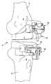
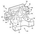
도 1은, 본 발명에 따라 형성되어 각각 대퇴골부 및 경골부 상에 위치된 절제 가이드 로케이터 내에 장착된 대퇴골 및 경골 절제 가이드의 사시도이다.
도 2는 사람 무릎 관절의 스캔 이미지의 개략도이다.
도 3은, 본 발명에 따른 컴퓨터 모델로 변환 후에, 도 2에 도시된 사람 무릎 관절의 스캔 이미지의 개략도이다.
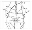
도 4는 본 발명에 따른 도 3의 컴퓨터 모델에서 제안된 절제 라인 및 중첩된 국부 좌표계를 도시하는, 도 3과 유사한 개략도이다.
도 5는 도 4와 유사한 개략도이다.
도 6은, 도 4 및 5와 유사한 개략도이지만, 본 발명에 따른 도 3의 컴퓨터 모델 내에 표시되는 대퇴골 및 경골 절제 가이드 로케이터를 도시한다.
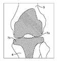
도 7은, 도 4, 5, 및 6과 유사한 개략도로서, 본 발명에 따른 모델 내에서 중첩된 대퇴골 및 경골 보철물(단면으로)의 디지털 표시를 나타낸다.
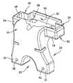
도 8은 본 발명에 따라 형성된 대퇴골 절제 가이드 로케이터의 사시도이다.
도 9는 도 8에 도시된 대퇴골 절제 가이드 로케이터의 후방 사시도이다.
도 10은 도 9에 도시된 대퇴골 절제 가이드 로케이터의 정면도이다.
도 11은 도 9 및 10에 도시된 대퇴골 절제 가이드 로케이터의 저면도이다.
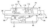
도 12는 본 발명에 따라 형성된 경골 절제 가이드 로케이터의 사시도이다.
도 13은 도 12에 도시된 경골 절제 가이드 로케이터의 저면 사시도이다.
도 14는 도 13에 도시된 경골 절제 가이드 로케이터의 평면도이다.
도 15는 도 14에 도시된 경골 절제 가이드 로케이터의 배면도이다.
도 16은 전형적인 경골 절제 가이드의 사시도이다.
도 17은 도 16에 도시된 경골 절제 가이드의 정면도이다.
도 18은 도 17에 도시된 경골 절제 가이드의 측면도이다.
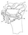
도 19는 대퇴골의 관절융기 상에 위치되는 대퇴골 절제 가이드 로케이터 내에 장착된 대퇴골 절개 가이드의 사시도이다.
도 20은 경골의 관절면 상에 위치되는 경골 절제 가이드 로케이터 내에 장착된 경골 절개 가이드의 사시도이다.
도 21은, 본 발명에 따라 형성되어 각각 경골부 및 거골부 상에 위치된 절제 가이드 로케이터 내에 장착된 경골 및 거골 절제 가이드의 사시도이다.
도 22는 본 발명에 따라 형성된 경골 절제 가이드의 사시도이다.
도 23은 본 발명에 따라 형성된 경골 절제 가이드 및 경골 절제 가이드 로케이터의 사시 분해도이다.
도 24는 본 발명에 따라 형성되어 경골의 하부 상에 위치되는 절제 가이드 로케이터 내에 장착된 경골 절제 가이드의 사시도이다.
도 25는 본 발명에 따라 형성되어 경골의 원위부 상에 위치되는 절제 가이드 로케이터 내에 장착된 경골 절제 가이드의 정면도이다.
도 26은 본 발명에 따라 형성되어 경골의 하부 상에 위치되는 경골 절제 가이드 및 경골 절제 가이드 로케이터의 측면 분해도이다.
도 27은 본 발명에 따라 형성된 경골 절제 가이드 및 경골 절제 가이드 로케이터의 적용과 사용으로 인해 절제된 원위부 경골의 개략도이다.
도 28은 본 발명에 따라 형성되어 거골의 일부 상에 위치되는 거골 절제 가이드 로케이터 내에 장착된 거골 절제 가이드의 사시도이다.
도 29는 본 발명에 따라 형성된 거골 절제 가이드 로케이터 내에 장착된 거골 절제 가이드의 사시도이다.
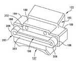
도 30은 본 발명에 따라 형성된 거골 절제 가이드 및 거골 절제 가이드 로케이터의 사시 분해도이다.
도 31은 본 발명에 따라 형성되어 발목 거골 상에 위치된 거골 절제 가이드 로케이터의 사시도이다.
도 32는 본 발명에 따라 형성되어 거골 전방부 상에 위치되는 절제 가이드 로케이터 내에 장착된 거골 절제 가이드의 정면도이다.
도 33은 본 발명에 따라 형성되어 거골 상부 상에 위치되는 거골 절제 가이드 및 거골 절제 가이드 로케이터의 측면 분해도이다.
도 34는 본 발명에 따라 형성된 거골 절제 가이드 및 거골 절제 가이드 로케이터의 적용과 사용으로 인해 절제된 거골의 개략도이다.These and other features and advantages of the present invention will be described in more detail in the following detailed description of the preferred embodiments of the invention, which are considered in conjunction with the accompanying drawings, will be apparent from the following detailed description, and like reference numerals designate similar Instruct configuration.
1 is a perspective view of a femur and tibial ablation guide formed in accordance with the present invention and mounted in an ablation guide locator located on the femur and tibia, respectively.
2 is a schematic diagram of a scanned image of a human knee joint.
3 is a schematic representation of the scanned image of the human knee joint shown in FIG. 2 after conversion to a computer model in accordance with the present invention.
FIG. 4 is a schematic diagram similar to FIG. 3 showing the ablation lines and superimposed local coordinate system proposed in the computer model of FIG. 3 in accordance with the present invention.
5 is a schematic view similar to FIG. 4.
Figure 6 is a schematic diagram similar to Figures 4 and 5, but showing the femur and tibial resection guide locators displayed within the computer model of Figure 3 in accordance with the present invention.
Figure 7 is a schematic diagram similar to Figures 4, 5 and 6, showing a digital representation of superimposed femur and tibial prostheses (in cross section) within a model according to the invention.
8 is a perspective view of a femur resection guide locator formed in accordance with the present invention.
9 is a rear perspective view of the femoral resection guide locator shown in FIG. 8.
FIG. 10 is a front view of the femur resection guide locator shown in FIG. 9.
FIG. 11 is a bottom view of the femur resection guide locator shown in FIGS. 9 and 10.
12 is a perspective view of a tibial ablation guide locator formed in accordance with the present invention.
FIG. 13 is a bottom perspective view of the tibial ablation guide locator shown in FIG. 12.
FIG. 14 is a plan view of the tibial ablation guide locator shown in FIG. 13.
FIG. 15 is a rear view of the tibial ablation guide locator shown in FIG. 14.
16 is a perspective view of a typical tibial ablation guide.
17 is a front view of the tibial ablation guide shown in FIG. 16.
18 is a side view of the tibial ablation guide shown in FIG. 17.
19 is a perspective view of a femoral incision guide mounted in a femoral ablation guide locator located on the articular ridge of the femur.
20 is a perspective view of a tibial incision guide mounted in a tibial ablation guide locator positioned on the articular surface of the tibia.
Figure 21 is a perspective view of the tibial and tibial ablation guides formed in accordance with the present invention and mounted in an ablation guide locator located on the tibial and tibial portions, respectively.
22 is a perspective view of a tibial ablation guide formed in accordance with the present invention.
23 is a perspective exploded view of a tibial resection guide and a tibial resection guide locator formed in accordance with the present invention.
24 is a perspective view of a tibial ablation guide formed in accordance with the present invention and mounted within an ablation guide locator located on the underside of the tibia.
25 is a front view of a tibial ablation guide formed in accordance with the present invention and mounted within an ablation guide locator located on the distal portion of the tibia.
26 is a side exploded view of a tibial resection guide and a tibial resection guide locator formed in accordance with the present invention and positioned on the underside of the tibia.
27 is a schematic diagram of distal tibia resected due to the application and use of a tibial resection guide and a tibial resection guide locator formed in accordance with the present invention.
FIG. 28 is a perspective view of a tibial ablation guide formed in accordance with the present invention and mounted within a tibial ablation guide locator positioned on a portion of the tavern. FIG.
29 is a perspective view of a talus ablation guide mounted within a talus ablation guide locator formed in accordance with the present invention.
30 is a perspective exploded view of a talus resection guide and a talus resection guide locator formed in accordance with the present invention.
Figure 31 is a perspective view of a talus ablation guide locator formed in accordance with the present invention and positioned on the ankle talus.
Figure 32 is a front view of a talus ablation guide formed in accordance with the present invention and mounted within an ablation guide locator located on the talus anterior.
Figure 33 is an exploded side view of a talus resection guide and a talus resection guide locator formed in accordance with the present invention and located on top of the talus.
34 is a schematic diagram of a talus resected due to the application and use of a talus resection guide and a talus resection guide locator formed in accordance with the present invention.
바람직한 실시예의 본 기술은, 본 발명의 전체 설명의 일부로 여겨지게 되는 첨부된 도면과 관련하여 기재되게 될 것이다. 도면은 스케일대로 도시될 필요는 없고, 본 발명의 특정 구조체는 규모가 과대하게 도시되거나 또는 명확성 및 간결성을 위하여 다소 개략 형태로 도시될 수 있다. "수평", "수직", "상방향", "하방향", "상부" 및 "저부"뿐만 아니라 그들의 파생어(예를 들면, "수평으로", "하방향으로", "상방향으로" 등)와 같은 상대적인 용어는 설명으로 이하 기술되거나 또는 도면에서 도시되는 배향을 참조하여 이해되어야 한다. 이러한 상대적인 용어는 설명 편의를 위한 것이고, 일반적으로 특정 배향을 필요로 하지 않을 것이다. "내측 방향으로" 대 "외측 방향으로", "길이 방향으로" 대 "측 방향으로" 등을 포함하는 용어들은 서로에 대해 상대적으로 또는 신장 축, 축, 회전 중심에 대해 상대적으로 적절히 이해되는 것이다. "연결된" 및 "상호 연결된"과 같은, 부착, 결합 등과 관련된 용어는, 명확하게 다르게 기재되지 않는다면, 구조체들이 중간 구조체뿐만 아니라, 이동가능하거나 또는 단단한 부착물 또는 관련물을 통하여 직접 또는 간접적으로 서로 고정되거나 또는 부착되는 관계를 언급한다. 단일 기계만 도시될 때, "기계" 용어는 또한, 여기서 설명되는 어떠한 하나 이상의 방법론을 수행하기 위해 한 명령 세트(또는 복수의 세트)를 개별적으로 또는 결합하여 수행하는 어떠한 기계들의 무리를 포함하는 것으로도 여겨질 것이다. 부착, 결합 또는 연결과 같은 "작동가능하게 연결된(operatively connected)" 용어는 관련 구조체가 그러한 관계에 의해 의도대로 작동하도록 한다. 청구항에서, 기능식 청구항이 사용된다면, 기능식 청구항은, 구조적 균등물뿐만 아니라 균등 구조체를 포함하는 기재된 기능을 수행하기 위해 쓰여진 설명 또는 도면에 의해 명백하게 기술되거나, 제안되거나, 또는 이해되는 구조체를 포함하는 것으로 의도된다.The present description of the preferred embodiments will be described with reference to the accompanying drawings, which are to be considered part of the overall description of the invention. The drawings need not be drawn to scale, and certain structures of the invention may be shown in excessive scale or in somewhat schematic form for clarity and brevity. "Horizontal", "vertical", "upward", "downward", "top" and "bottom" as well as their derivatives (eg "horizontally", "downward", "upwardly") Relative terms, etc., should be understood with reference to the orientation described below in the description or shown in the drawings. These relative terms are for convenience of description and generally will not require a particular orientation. Terms including "inward direction" to "outward direction", "in the longitudinal direction" to "lateral direction", etc., are properly understood relative to each other or relative to the axis of elongation, axis, rotation, etc. . Terms relating to attachment, bonding, and the like, such as "connected" and "interconnected", unless specifically stated otherwise, refer to structures that are fixed to each other directly or indirectly, not only through intermediate structures, but also through movable or rigid attachments or related materials. Reference is made to the attached or attached relationship. When only a single machine is shown, the term "machine" also includes any group of machines that perform one instruction set (or plurality of sets) individually or in combination to perform any one or more methodologies described herein. Will also be considered. The term "operatively connected" such as attachment, coupling or connection allows the associated structure to operate as intended by such a relationship. In the claims, where a functional claim is used, the functional claim includes a structure that is expressly described, suggested, or understood by the description or drawings written to perform the described function, including the structural equivalents as well as the equivalent structures. It is intended to be.
본 발명은, 컴퓨터 단층촬영 스캐너(CT), 자기공명영상장치(MRI) 또는 의료 영상 기술 등에 의해 결정됨으로써, 환자의 해부에 기초되는 맞춤형 수술 기구, 가이드 및 고정 장치(fixture)를 제공한다. 예를 들면, CT 또는 MRI 스캔 이미지(1) 또는 일련의 이미지는 골반(pelvis)으로부터의 사지(limb) 부분 또는 발(도 2 및 3) 부분을 포함하는 환자 무릎(1) 또는 발목(1a)으로부터 얻을 수 있다. 슬관절 전치환술(total knee replacement)의 경우에, CT 또는 MRI 스캔 이미지 데이터는 이후에, 보통 컴퓨터 소프트웨어로 구현되는 전문화된 모델링 방법을 사용하여 임플란트 정렬, 형태 및 크기를 결정하기 위하여, 예를 들면, DICOM 이미지 포맷으로부터 보통 골반, 대퇴골(femur), 슬개골(patella), 경골(tibia) 또는 발을 포함하는 하지(lower limb)의 솔리드 컴퓨터 모델(3)로 변환된다. CT 또는 MRI 스캔 이미지 데이터(1)로부터 기인되는 컴퓨터 생성 솔리드 모델(3)은 보통, 이미지화된 구조체, 예를 들면, 이미지화된 뼈의 표면 형태(surface topography) 또는 이미지화된 근막(fascia)의 윤곽을 둘러싸는 표면 윤곽에 관한 정확하고 정밀한 정보를 포함한다. 표면 형태는 위치, 형상, 크기 및 함몰부 및 돌기부 등의 표면 특성의 분포를 의미하는 것으로 이해될 것이다.The present invention provides customized surgical instruments, guides and fixtures based on the anatomy of a patient, as determined by computed tomography scanner (CT), magnetic resonance imaging device (MRI) or medical imaging techniques. For example, a CT or
여기서 참조로 포함된, 스와일렌스(Swaelens) 등에 특허 허여된 미국 특허 제5,768,134호에 기재된 방법에서, CT 또는 MRI 스캔 이미지 데이터(1)를 본 발명으로 이용가능한 솔리드 컴퓨터 모델(3)로 적절히 변환하는 것이 알려지게 되었다. 일부 실시예에서, 이미지는 하지, 즉, 환자의 골반, 대퇴골, 슬개골, 경골 및/또는 발의 이미지가 CT 또는 MRI 장치 또는 다른 디지털 이미지 캡쳐 및 처리 장치(도 2 및 3)를 사용하여 만들어진다. 이러한 스캐닝은 대퇴골(5) 및 경골(6)의 인접부를 포함하는, 질병에 걸린 무릎 또는 발목관절의 스캔 이미지를 생성시킨다. 이미지 데이터(1)는 처리 장치에서 먼저 처리되고, 그 후에 처리된 디지털화된 이미지 데이터를 사용하여 모델이 생성된다.In the method described in US Pat. No. 5,768,134 to Swaelens et al., Incorporated herein by reference, the appropriate conversion of CT or MRI scan image data (1) into solid computer models (3) usable with the present invention. It became known. In some embodiments, the image is made of the lower extremity, ie, the image of the patient's pelvis, femur, patella, tibia and / or foot using a CT or MRI device or other digital image capture and processing device (FIGS. 2 and 3). This scanning produces a scanned image of the diseased knee or ankle joint, including the proximal portion of the
본 발명에 따르면, 구성의 배치 및 정렬(10)을 위한 사전에 정해진 기준 위치(9)와 같은 추가 외부 디지털화된 정보(8)의 조작 및 도입을 포함하는 디지털화된 이미지 데이터의 상호작용 처리 및 준비가 수행되고, 따라서 수술 동안에 절제가 요구될 수술 부위로의 조정은 컴퓨터 모델(3)(도 4 및 5) 상에서 계획되고 맵핑된다. 디지털화된 이미지 데이터의 상호작용 처리 후에, 환자 특정 수술 기구, 보철물(7a, 7b)(도 7) 가이드, 또는 고정 장치의 고 해상도 디지털 표시를 얻기 위하여 원래 CAD 데이터로 되돌아 가는 것이 가능하고, 이 디지털 표시를 환자의 이미지 데이터 모델에 추가하도록 한다.According to the invention, the interactive processing and preparation of digitized image data, including the manipulation and introduction of additional external
예를 들면, 본 발명의 시스템이 슬관절 치환술에 사용될 때, 대퇴골 절제 가이드 마운트(mount)(20)의 디지털 표시는 환자 이미지 데이터 모델(도 1 및 6)에 추가될 수 있다. 슬관절 전치환술의 맥락에서, 수술 동안에 대퇴골(5)의 빼 절제를 안내하고 제어하는데 사용되는 대퇴골 절제 가이드(26)의 정확하고 정밀한 배치를 보장하기 위하여, 대퇴골 절제 가이드 마운트(20)는 환자의 대퇴골의 노출된 관절융기(condyle) 상의 설치를 위해 형성될 수 있다. 대퇴골 절제 가이드(26)가 다양한 형태 및 형상을 가질 수 있지만, 본 발명은 출원인 라이트 메디컬 테크놀러지 아이엔씨(Wright Medical Technoligy, Inc.)에 의해 현재 제공되는 원위부 절제 가이드(라이트 메디컬 제품 제K001-2659호)를 참조하여 기술될 것이다. 중요하게도, 다른 외부 고정 장치 필요 없이 또는 관절융기 사이 노치(intercondylar notch)를 통하여 그리고 대퇴골 샤프트 축을 따라 대퇴골(5)을 상측 방향으로 관통하여 삽입되는 골수내 줄기(intramedullary stem)의 사용 없이, 대퇴골 절제 가이드 마운트(20)는 이러한 정확하고 정밀한 배치 기능을 제공한다. 경골 절제 가이드 마운트(22)의 디지털 표시는 또한 환자 이미지 데이터 모델(도 6)에 추가될 수 있다. 수술 동안에 노출된 경골의 상관절면(superior articular surface)의 절제를 안내하고 제어하는데 사용되는 경골 절제 가이드(28)의 정확하고 정밀한 배치를 보장하기 위하여, 경골 절제 가이드 마운트(22)는 환자의 경골(6)의 노출된 상관절면 상에 설치를 위해 유사하게 형성된다.For example, when the system of the present invention is used for knee replacement, a digital representation of the femoral resection guide mount 20 can be added to the patient image data model (FIGS. 1 and 6). In the context of total knee arthroplasty, in order to ensure accurate and precise placement of the femoral resection guide 26 used to guide and control the subtraction of the
도 8 내지 11을 참조하면, 본 발명의 일 실시예에 따른 대퇴골 절제 가이드 마운트(20)가 스테레오 리소그래피(stereo lithography), 선택적 레이저 소결(selective laser sintering) 등 제조 설비에 관련되어 사용하기 적합한 형태의 탄성 중합체 재료로 형성된다. 절제 가이드 마운트(20)는 양분형 관절융기 요크(yolk)(25) 및 가이드 수용부(29)를 구비하는 단일 블록을 포함한다. 양분형 요크(25)는 베이스(33)로부터 외측 방향으로 돌출하는 한 쌍의 이격된 암(30, 31)을 포함한다. 암(30)은 하부 결합면 또는 뼈 결합면(36) 및 관통 보어(38)를 포함하고, 암(31)은 하부 결합면 또는 뼈 결합면(40) 및 관통 보어(42)를 포함한다. 이전에 설명된 이미지 작업을 통하여, 뼈 결합면(36, 40)은 환자의 원래 뼈의 선택된 부위의 해부학적 표면 형상과 상호 보완적으로 매칭되도록 형성된다. 도 8 내지 11의 실시예의 대퇴골 절제 가이드 마운트(20)에서, 선택된 뼈 부위는 환자 대퇴골의 관절융기를 포함한다.8 to 11, the femoral resection guide mount 20 according to an embodiment of the present invention is of a type suitable for use in connection with manufacturing equipment such as stereo lithography, selective laser sintering, and the like. It is formed of an elastomeric material. The
가이드 수용부(29)는 베이스(33)로부터 반대 방향으로 암(30, 31)에 이격되어 외측 방향으로 돌출하는 한 쌍의 날개(44, 46)를 포함한다. 긴 슬롯(52)이 베이스(33)와 가이드 하우징(49) 사이에 형성되도록, 각각의 날개(44, 46)는 가이드 하우징(49)을 지지하기 위하여 상측 방향으로 돌출하는 파일론(pylon)(48)을 포함한다. 슬롯(52)은, 뼈 절제를 위해 일반적으로 사용되는 형태의 전형적인 수술용 톱이 대응되게 위치되고 대응되는 크기를 가지는 절제 가이드(26)에서의 슬롯을 접촉 없이 또는 절제 가이드 로케이터(20)와 단지 부수적인 접촉만으로 관통하여 지나가도록 하는, 크기 및 형상을 가진다. 대퇴골 절제 가이드(26)의 외부 프로파일(profile)에 상호 보완적인 형상을 가지는 환형 벽(55)이 후방 벽(61)에 대하여 실질적으로 수직으로 외측 방향으로 돌출하고, 따라서 리세스(58)를 형성한다. 일부 바람직한 실시예에서, 리세스(58)는 "프레스 끼워맞춤(press fit)"으로 대퇴골 절제 가이드(26)를 수용하도록 하는 크기를 가진다. 프레스 끼워맞춤에 의해, 대퇴골 절제 가이드(26)가 리세스(58) 내로 끼워질 때, 탄성 에너지를 저장하도록 탄성적으로 편향되거나 압축되기 위하여 환형 벽(55)이 충분한 탄성을 가진다는 것이 이해될 것이다. 물론, 대퇴골 절제 가이드(26)가 리세스(58)의 외주부 형상에 상호 보완적인 외주부 형상을 가지지만, 프레스 끼워맞춤 실시예를 위하여 조금 더 큰 크기를 가질 것이라는 것도 또한 이해될 것이다. 또한, 대퇴골 절제 가이드(26)는 환형 벽(55)과 단지 마찰 결합만으로도 리세스(58) 내에 보유될 수 있고, 또는, 바람직하지 않은 실시예에서, 절제 가이드(26)는, 수술 접촉 없이 또는 환형 벽(55)과 단지 부수적인 결합만으로 리세스(58) 내로 간단하게 슬라이드 될 수 있다. 제1 관통 보어(62, 64)가 서로 이격되어 후방 벽(61)에 형성되고, 제2 관통 보어(67, 69)가 각각의 제1 관통 보어(62, 64)와 관련되어 있다. 도 8 내지 11에 도시된 실시예에서, 제1 관통 보어(62, 64)는 커다란 정사각형 또는 직사각형 개구부이고, 제조를 용이하게 하고, 재료 사용을 감소시키고, 박아 넣어지는 핀, 와이어, 나사, 또는 대퇴골 절제 가이드(26) 상에 제공되는 복수의 인접한 보어를 관통하는 다른 적합한 체결구를 위한 충분한 공간을 제공하는 형상을 가진다. 그루브(70)가 베이스(33)의 외부면에 형성되고, 절제 가이드(26)와 매칭하기 위하여 리세스(58)에 대하여 중심에 위치된다.The
도 12 내지 18을 참조하면, 본 발명의 일 실시예에 따른 경골 절제 가이드 마운트(22)가 스테레오 리소그래피, 선택적 레이저 소결 등 제조 설비에 관련되어 사용하기 적합한 형태의 탄성 중합체 재료로 형성되고, 예를 들면, 폴리아미드 분말 상환 프로토타입(polyamide powder repaid prototype) 재료가 선택적 레이저 소결에 대하여 사용하기 적합하다. 절제 가이드 마운트(22)는 양분형 요크(75) 및 가이드 수용부(79)를 구비하는 단일 블록을 포함한다. 양분형 요크(75)는 베이스(83)로부터 외측 방향으로 돌출하는 한 쌍의 이격된 암(80, 81)을 포함한다. 암(80)은 하부면(86)을 포함하고, 암(81)은 하부면(90)을 포함한다.12 to 18, the tibial ablation guide mount 22 according to one embodiment of the present invention is formed of an elastomeric material in a form suitable for use in connection with manufacturing equipment such as stereo lithography, selective laser sintering, and the like. For example, polyamide powder repaid prototype materials are suitable for use for selective laser sintering. The
가이드 수용부(79)는 베이스(83)로부터 반대 방향으로 암(80, 81)에 이격되어 외측 방향으로 돌출하는 한 쌍의 날개(84, 86)를 포함한다. 긴 슬롯(94)이 베이스(83)와 가이드 하우징(89) 사이에 형성되도록, 각각의 날개(84, 86)는 가이드 하우징(89)을 지지하기 위하여 상측 방향으로 돌출하는 파일론(88)을 포함한다. 슬롯(94)은, 뼈 절제를 위해 일반적으로 사용되는 형태의 전형적인 수술용 톱이 대응되게 위치되고 대응되는 크기를 가지는 절제 가이드(28)에서의 슬롯을 접촉 없이 또는 절제 가이드 로케이터(22)와 단지 부수적인 접촉만으로 관통하여 지나가도록 하는, 크기 및 형상을 가진다. 경골 절제 가이드(28)의 외부 프로파일에 상호 보완적인 형상을 가지는 환형 벽(95)이 후방 벽(101)에 대하여 실질적으로 수직으로 외측 방향으로 돌출하고, 따라서 리세스(108)를 형성한다. 리세스(108)는 프레스 끼워맞춤으로 경골 절제 가이드(28)를 수용하도록 하는 크기를 가진다. 제1 관통 보어(112, 114)가 서로 이격되어 후방 벽(101)에 형성되고, 제2 관통 보어(117, 119)가 각각의 제1 관통 보어(112, 114)와 관련되어 있다.The
이전에 기술된 디지털 이미지 모델(3)로 돌아와서, 환자의 대퇴골 이미지 데이터에 추가된 절제 가이드 마운트(20)의 일반화된 디지털 모델을 고려하면, 환자 대퇴골의 해부학적 표면 형상은, 예를 들면, 관절융기면 표면 형태는, 암(30, 31)의 각각의 하부면(36) 및 하부면(40)에 상호 보완적으로 맵핑될 수 있다. 디지털 이미지의 상호 보완적인 맵핑에 따라, 뼈 표면 예를 들면, 관절융기, 피질(cortical), 또는 관절면 상의 국부 돌기부는 하부면(36) 또는 하부면(40) 상에서 국부 함몰부가 되도록 하고, 뼈 표면 상의 국부 함몰부는 하부면(36) 또는 하부면(40) 상에서 국부 돌기부가 되도록 하는 결과를 초래한다는 것이 또한 이해될 것이다. 이러한 방식으로, 각각의 하부면(36) 및 하부면(40)은 환자 대퇴골의 선택된 부위의 해부학적 표면 형상에 상호 보완적이고 실질적으로 좌우변환 이미지(mirror image)로 재형성된다. 이러한 상호 보완적인 뼈 표면 맵핑의 결과로써, 다른 외부 또는 내부 가이드 고정 장치 필요 없이, 절제 가이드 마운트(20)는, 환자의 원래 대퇴골, 예를 들면, 관절융기면에 대응하는 부분의 상호 보완적인 표면 형태로 해제가능하게 "고정(lock)"된다. 다시 말해서, 대퇴골 절제 가이드 마운트(20)의 등각(conformal) 뼈 결합면에 형성된, 뼈 표면 거칠기(bone surface asperities)에 대응하는 함몰부에서 뼈 표면 거칠기의 결합은, 대퇴골 절제 가이드 마운트(20)와 관절융기면 사이에서의 측방향 미끄러짐과 같은 상대적인 이동이 거의 또는 전혀 발생하지 않는 것을 보장한다. 실질적으로 동일한 맵핑이 환자 특정 경골 절제 가이드 마운트(22)의 설계에 관하여 수행된다.Returning to the previously described
환자 대퇴골과 절제 가이드 마운트(20) 사이의 가상 정렬 결과의 시각적 표시가 생성되어 제조 전에 결과(도 1, 10, 20)의 승인을 얻기 위하여 외과의사에게 전달된다. 외과의사의 승인 받는 즉시, 절제 가이드 마운트(20), 적합한 경우에는 절제 가이드 마운트(22)가 제조되어 수술에서 사용되기 위하여 외과의사에게로 전달된다.A visual indication of the virtual alignment result between the patient's femur and the
슬관절 전치환술 동안에, 본 발명은 이하 방법으로 사용된다. 외과의사는 먼저, 절제 가이드 마운트(20)의 하부면(36, 40)이 대퇴골(5)의 노출된 표면(4)의 표면 형태와 해제가능하게 "상호고정(interlock)"하도록 대퇴골과 서로 확실하게 결합할 때까지 절제 가이드 마운트(20)를 대퇴골(5) 상에 배향한다. 절제 가이드 마운트(20)가 환자 대퇴골 상에 고정된 상태에서, 외과의사는 적절하게 형성된 원위부 절제 가이드(Distal Resection Guide)(26)(예를 들면, 라이트 메디컬 테크놀러지 아이엔씨. 제품 제K001-2659호)를 절제 가이드 마운트(20)의 리세스(58)에 프레스 끼워 맞춘다. 도 19 내지 20에 도시된 바와 같이, 이는, 절제 가이드 마운트(20) 및 특히 절제 가이드 마운트(20)의 가이드 수용부(29)가 절제 가이드(26)와 환자의 뼈 사이에 개재되도록 한다. 핀이 절제 가이드(26)의 관통 보어 내로 박아 넣어지지만, 바람직하게는, 핀은 절제 가이드 마운트(20)의 관통 보어(62, 64 또는 67, 69)를 형성하는 부분과 접촉하지 않는다. 이러한 관통 보어는 보통 절제 가이드 마운트(20) 상의 최원위부에 있다. 절제 가이드 마운트(20)가 제 위치에 확실하게 고정된 상태에서, 드릴 비트(bit)가 관통 보어(38, 42), 후방 벽(61)에 형성된 관통 보어(62, 64) 내로 및/또는 제2 관통 보어(67, 69) 내로 진행된다. 드릴이 관통 보어(38, 42) 내의 대퇴골 내로 약 15mm 관통하는 것이 보통 바람직하고, 따라서 드릴 구멍이 원위부 절개 후에 생기게 될 것이다. 커다란 원위부 절개의 경우에 굴곡 구축(flexion contracture)을 보정하기 위하여 늘어난 구멍 깊이가 필요할 수 있다. 추가 안정성을 위하여, 고정 핀(도시되지 않음)이 관통 보어(38, 42)에 남겨질 수 있지만, 절제 전에 제거되어야만 한다. 절제 가이드 마운트(20)가 선택된 뼈 부위에 대하여 이와 같이 정밀하게 위치되고, 절제 가이드(26)-절제 가이드 마운트(20) 구성체가 환자의 뼈에 적합하게 고정된 상태에서, 외과의사는 환자의 뼈를 절제하기 위하여 전형적인 수술용 블레이드 및 절제 가이드(26)의 절제 슬롯을 사용한다.During total knee arthroplasty, the present invention is used in the following manner. The surgeon first reliably secures the femur and each other such that the
본 발명의 시스템이 발목관절 치환술(ankle replacement surgery)에 사용될 때, 경골 절제 가이드 마운트(120) 및 거골(talar) 절제 가이드 마운트(122)가 대퇴골 절제 가이드 마운트(20) 및 경골 절제 가이드 마운트(22)에서와 거의 동일한 방식으로 환자의 하부 경골(123) 및 상부 거골(124)에 각각 형성되고 장착된다. 더욱 상세하게는, 본 발명의 일 실시예에 따른 경골 절제 가이드 마운트(120)가 스테레오 리소그래피 등 제조 설비에 관련되어 사용하기 적합한 형태의 탄성 중합체 재료로 형성된다(도 22). 절제 가이드 마운트(120)는 베이스(127)로부터 상측 방향으로 돌출하는 십자형 경골 요크(125) 구비하는 단일 바디를 포함하고, 단일 바디는 가이드 수용 리세스(129)를 더 형성한다. 십자형 요크(125)는 중앙 포스트(post)(133)로부터 외측 방향으로 돌출하는 한 쌍의 이격된 암(130, 131)을 포함한다. 암(130, 131) 및 중앙 포스트(133)는 각각 환자의 하부 경골의 대응부의 윤곽에 상호 보완적인 등각 뼈 결합면(134)을 가진다(도 26). 이전에 설명된 이미지 작업을 통하여, 암(130, 131) 및 중앙 포스트(133)의 등각 뼈 결합면(134)은 환자의 원래 뼈의 선택된 부위의 해부학적 표면 형상과 상호 보완적으로 매칭되도록 형성된다. 경골 절제 가이드 마운트(120)에 관하여, 선택된 뼈 부위는 환자 경골의 하부면을 포함한다.When the system of the present invention is used for ankle replacement surgery, the tibial
파일롯 블록(135)이 암(130, 131)의 교차점에 인접한 중앙 포스트(133)로부터 외측 방향으로 돌출한다. 지지 블록(136)이 파일롯 블록(135)에 이격되어 베이스(127) 상에 위치된다. 가이드 수용 리세스(129)는, 베이스(127) 상에서 반대 방향으로 중앙 포스트(133)의 각 측면으로부터 외측 방향으로 연장하는 한 쌍의 날개(144, 146)와 날개 사이에 위치되는 지지 블록(136)에 의해 형성된다. 각각의 날개(144, 146)는 경골 절제 가이드(150)의 측 방향 지지를 제공하도록 베이스(127)로부터 외측 방향으로 돌출하는 파일론(148)을 포함한다(도 21 및 22). 긴 슬롯(152)이 파일롯 블록(135) 아래이나 지지 블록(136)의 상부의 베이스(127)의 중앙부에 횡방향으로 형성된다. 각각의 날개(144, 146)는 또한, 중앙 포스트(133)에 대하여 일정 각으로 배향된 슬롯(153)을 형성한다. 슬롯(152, 153)은, 뼈 절제를 위해 일반적으로 사용되는 형태의 전형적인 수술용 톱(151)(도 26)이 대응되게 위치되고 대응되는 크기를 가지는 절제 가이드(150)에서의 슬롯을 접촉 없이 또는 절제 가이드 로케이터(120)와 단지 부수적인 접촉만으로 관통하여 지나가도록 하는, 크기 및 형상을 가진다.The
도 21 및 23을 참조하면, 경골 절제 가이드(150)는, 브리지 빔(157)의 양 단부로부터 경사지게 분기하여 하측 및 외측 방향으로 돌출하는 한 쌍의 암(155)을 포함한다. 이러한 방식으로, 경골 절제 가이드(150)의 형상은, 파일롯 블록(135), 지지 블록(136), 및 파일론(148)의 내측 방향으로 마주보는 면들에 의해 형성되는 가이드 수용 리세스(129)의 형상에 상호 보완적이다. 브리지 빔(157)은 긴 슬롯(156)을 형성하고, 각각의 암(155)은, 절제 가이드 마운트(120)에 조립될 때, 베이스(127)에서 각각 긴 슬롯(152) 및 슬롯(153)과 동일한 공간에서 정렬되는 슬롯(158)을 형성한다. 파일럿 블록(135), 지지 블록(136), 및 파일론(148)의 내측 방향으로 마주보는 면들(149)은, 함께 가이드 수용 리세스(129)를 형성하고, 경골 절제 가이드(150)의 외부 프로파일에 상호 보완적인 형상을 가진다. 일부 바람직한 실시예에서, 가이드 수용 리세스(129)는 프레스 끼워맞춤으로 경골 절제 가이드(150)를 수용하도록 하는 크기를 가진다. 프레스 끼워맞춤에 의해, 경골 절제 가이드(150)가 가이드 수용 리세스(129) 내로 끼워질 때, 탄성 에너지를 저장하도록 탄성적으로 편향되거나 압축되기 위하여 파일럿 블록(135), 지지 블록(136), 및 파일론(148)의 내측 방향으로 마주보는 면들(149)이 충분한 탄성을 가진다는 것이 이해될 것이다. 물론, 경골 절제 가이드(150)가 가이드 수용 리세스(129)의 외주부 형상에 상호 보완적인 외주부 형상을 가지지만, 프레스 끼워맞춤 실시예를 위하여 조금 더 큰 크기를 가질 것이라는 것도 또한 이해될 것이다. 또한, 경골 절제 가이드(150)는 파일럿 블록(135), 지지 블록(136), 및 파일론(148)의 내측 방향으로 마주보는 면들(149)과 단지 마찰 결합만으로도 가이드 수용 리세스(129) 내에 보유될 수 있고, 또는, 바람직하지 않은 실시예에서, 경골 절제 가이드(150)는, 수술 접촉 없이 또는 파일럿 블록(135), 지지 블록(136), 및 파일론(148)의 내측 방향으로 마주보는 면들(149)과 단지 부수적인 결합만으로 가이드 수용 리세스(129) 내로 간단하게 슬라이드 될 수 있다.21 and 23, the
도 21 및 28 내지 33을 참조하면, 본 발명의 일 실시예에 따른 거골 절제 가이드 마운트(122)가 스테레오 리소그래피, 선택적 레이저 소결 등 제조 설비에 관련되어 사용하기 적합한 형태의 탄성 중합체 재료로 형성되고, 예를 들면, 폴리아미드 분말 상환 프로토타입 재료가 선택적 레이저 소결에 대하여 사용하기 적합하다. 거골 절제 가이드 마운트(122)는 또한, 환자의 상부 거골(124)의 대응부의 윤곽에 상호 보완적인 등각 뼈 결합면(137)을 포함한다(도 21, 28, 및 31 내지 34). 이전에 설명된 이미지 작업을 통하여, 거골 절제 가이드 마운트(122)의 등각 뼈 결합면(137)은 환자의 원래 뼈의 선택된 부위의 해부학적 표면 형상과 상호 보완적으로 매칭되도록 형성된다. 거골 절제 가이드 마운트(122)에 관하여, 선택된 뼈 부위는 환자 거골의 외부, 상부면을 포함한다.21 and 28 to 33, the tibial
거골 절제 가이드 마운트(122)는 중앙 가이드 수용 리세스(179) 및 한 쌍의 관통 보어(180)를 형성하는 단일 블록을 포함한다(도 30). 가이드 수용 리세스(179)는 베이스(183)로부터 반대 방향의 외측 방향으로 돌출하는 한 쌍의 날개(184, 186)의 내측으로 마주보는 면들(181)에 의해 형성된다. 긴 슬롯(194)이 베이스(183) 내에 가이드 하우징(189) 아래에 형성되도록, 각각의 날개(184, 186)는 가이드 하우징(189)을 지지하기 위하여 상측 방향으로 돌출하는 파일론(188)을 포함한다(도 31 및 33). 슬롯(194)은, 뼈 절제를 위해 일반적으로 사용되는 형태의 전형적인 수술용 톱(151)이 대응되게 위치되고 대응되는 크기를 가지는 거골 절제 가이드(200)에서의 슬롯(196)을 접촉 없이 또는 거골 절제 가이드 로케이터(122)와 단지 부수적인 접촉만으로 관통하여 지나가도록 하는, 크기 및 형상을 가진다. 거골 절제 가이드(200)의 외부 프로파일에 상호 보완적인 형상을 가지는 환형 벽(195)이 후방 벽에 대하여 실질적으로 수직으로 외측 방향으로 돌출하고, 따라서 가이드 수용 리세스(179)를 추가로 형성한다.The talus
도 28, 29, 및 30을 참조하면, 거골 절제 가이드(200)는 한 쌍의 대향하는 평행한 플레이트(202, 203)를 포함하여, 플레이트 사이에서 긴 슬롯(196)을 형성하고, 거골 절제 가이드(200)는 플레이트의 단부에서 날개(206)에 의해서 서로 결합된다. 이러한 방식으로, 거골 절제 가이드(200)의 형상은, 날개(184, 186), 베이스(183), 및 파일론(188)의 내측 방향으로 마주보는 면들에 의해 형성되는 가이드 수용 리세스(179)의 형상에 상호 보완적이다. 가이드 수용 리세스(179)는 프레스 끼워맞춤으로 거골 절제 가이드(200)를 수용하도록 하는 크기를 가진다. 물론, 거골 절제 가이드(200)가 가이드 수용 리세스(179)의 외주부 형상에 상호 보완적인 외주부 형상을 가지지만, 프레스 끼워맞춤 실시예를 위하여 조금 더 큰 크기를 가질 것이라는 것도 또한 이해될 것이다. 또한, 거골 절제 가이드(200)는 날개(184, 186), 베이스(183), 및 파일론(188)의 내측 방향으로 마주보는 면들(181)과 단지 마찰 결합만으로도 가이드 수용 리세스(179) 내에 보유될 수 있고, 또는, 바람직하지 않은 실시예에서, 거골 절제 가이드(200)는, 수술 접촉 없이 또는 날개(184, 186), 베이스(183), 및 파일론(188)의 내측 방향으로 마주보는 면들(181)과 단지 부수적인 결합만으로 가이드 수용 리세스(179) 내로 간단하게 슬라이드 될 수 있다.Referring to Figures 28, 29, and 30, the
이전에 기술된 디지털 이미지 모델(3)로서, 환자의 하부 경골 이미지 데이터에 추가된 경골 절제 가이드 마운트(120)의 일반화된 디지털 모델을 고려하면, 예를 들면, 표면 형태인, 환자의 하부 경골의 해부학적 표면 형상은, 암(130, 131) 및 중앙 포스트(133)의 각각의 등각 뼈 결합면(134), 즉, 뼈 고유의 표면 형태와 결합하는 표면에 상호 보완적으로 맵핑될 수 있다. 디지털 이미지의 상호 보완적인 맵핑에 따라, 뼈 표면 상의 국부 돌기부는 암(130, 131) 및 중앙 포스트(133)의 등각 뼈 결합면(134) 상에서 국부 함몰부가 되도록 하고, 뼈 표면 상의 국부 함몰부는 암(130, 131) 및 중앙 포스트(133)의 등각 뼈 결합면(134) 상에서 국부 돌기부가 되도록 하는 결과를 초래한다는 것이 또한 이해될 것이다. 이러한 방식으로, 암(130, 131) 및 중앙 포스트(133)의 각각의 등각 뼈 결합면(134)은 환자의 하부 경골의 선택된 부위의 해부학적 표면 형상에 상호 보완적이고 실질적으로 좌우변환 이미지로 재형성된다. 이러한 상호 보완적인 뼈 표면 맵핑의 결과로써, 다른 외부 또는 내부 가이드 고정 장치 필요 없이, 경골 절제 가이드 마운트(120)는, 환자의 원래 경골의 대응하는 부분의 상호 보완적인 표면 형태로 해제가능하게 "고정(lock)"된다. 다시 말해서, 경골 절제 가이드 마운트(120)의 등각 뼈 결합면(134)에 형성된, 뼈 표면 거칠기에 대응하는 함몰부에서 뼈 표면 거칠기의 결합은, 경골 절제 가이드 마운트(120)와 경골면 사이에서의 측방향 미끄러짐과 같은 상대적인 이동이 거의 또는 전혀 발생하지 않는 것을 보장한다. 실질적으로 동일한 맵핑이 환자 특정 거골 절제 가이드 마운트(122)의 설계에 관련된다.Considering the generalized digital model of the tibial
환자의 하부 경골과 절제 가이드 마운트(120) 사이뿐만 아니라 환자 상부 거골과 절제 가이드 마운트(122) 사이의 가상 정렬 결과의 시각적 표시가 생성되어 제조 전에 결과의 승인을 얻기 위하여 외과의사에게 전달된다. 외과의사의 승인 받는 즉시, 절제 가이드 마운트(120) 및 절제 가이드 마운트(122)가 제조되어 수술에서 사용되기 위하여 외과의사에게로 전달된다.A visual indication of the virtual alignment result between the patient's lower tibia and the
발목관절 전치환술 동안에, 본 발명은 이하 방법으로 사용된다. 외과의사는 먼저, 절제 가이드 마운트(120)의 암(130, 131) 및 중앙 포스트(133)의 등각 뼈 결합면(134)이 하부 경골(123)의 노출된 표면의 표면 형태와 해제가능하게 "상호고정"하도록 경골과 서로 확실하게 결합할 때까지 절제 가이드 마운트(120)를 하부 경골(123) 상에 배향한다. 절제 가이드 마운트(120)가 환자의 하부 경골 상에 고정된 상태에서, 외과의사는 적절하게 형성된 원위부 절제 가이드(150)를 절제 가이드 마운트(120)의 가이드 수용 리세스(129)에 프레스 끼워 맞춘다. 이는, 절제 가이드 마운트(120)가 절제 가이드(150)와 환자의 뼈 사이에 개재되도록 한다(도 21, 24 및 25). 절제 가이드 마운트(120)가 선택된 뼈 부위에 대하여 정밀하게 위치되고, 절제 가이드(150)-절제 가이드 마운트(120) 구성체가, 등각 뼈 결합면(134)에 형성된, 뼈 표면 거칠기에 대응하는 함몰부에서 뼈 표면 거칠기의 결합에 의해 환자의 뼈에 적합하게 고정된 상태에서, 외과의사는 환자의 뼈를 절제하기 위하여 전형적인 수술용 블레이드(151) 및 절제 가이드(150)의 절제 슬롯(152, 153)을 사용한다(도 27).During ankle arthroplasty, the present invention is used in the following manner. The surgeon first determines that the
유사한 방식으로, 거골 절제 가이드 마운트(122)가 환자의 거골 이미지 데이터에 추가될 때, 환자의 상부 거골의 해부학적 표면 형상, 예를 들면, 표면 형태는, 등각 뼈 결합면(137)에 상호 보완적으로 맵핑될 수 있다. 디지털 이미지의 상호 보완적인 맵핑에 따라, 뼈 표면 상의 국부 돌기부는 등각 뼈 결합면(137) 상에서 국부 함몰부가 되도록 하고, 뼈 표면 상의 국부 함몰부는 등각 뼈 결합면(137) 상에서 국부 돌기부가 되도록 하는 결과를 초래한다는 것이 또한 이해될 것이다. 이러한 방식으로, 등각 뼈 결합면(137)은 환자의 하부 경골의 선택된 부위의 해부학적 표면 형상에 상호 보완적이고 실질적으로 좌우변환 이미지로 재형성된다. 이러한 상호 보완적인 뼈 표면 맵핑의 결과로써, 다른 외부 또는 내부 가이드 고정 장치 필요 없이, 거골 절제 가이드 마운트(122)는, 환자의 원래 거골의 대응하는 부분의 상호 보완적인 표면 형태로 해제가능하게 "고정(lock)"된다.In a similar manner, when the talus
발목관절 전치환술을 지속하기 위하여, 외과의사는 먼저 절제 가이드 마운트(122)의 등각 뼈 결합면(137)이 상부 거골(124)의 노출된 표면의 표면 형태와 "고정"할 때까지 절제 가이드 마운트(122)를 상부 거골(124) 상에 배향한다. 절제 가이드 마운트(122)가 환자의 상부 거골 상에 고정된 상태에서, 외과의사는 적절하게 형성된 원위부 절제 가이드(200)를 절제 가이드 마운트(122)의 가이드 수용 리세스(179)에 프레스 끼워 맞춘다. 이는, 절제 가이드 마운트(122)가 절제 가이드(200)와 환자의 뼈 사이에 개재되도록 한다(도 21, 28, 32, 및 33). 절제 가이드 마운트(122)가 선택된 뼈 부위에 대하여 정밀하게 위치되고, 절제 가이드(200)-절제 가이드 마운트(122) 구성체가, 등각 뼈 결합면(137)에 형성된, 뼈 표면 거칠기에 대응하는 함몰부에서 뼈 표면 거칠기의 결합에 의해 환자의 뼈에 적합하게 고정된 상태에서, 외과의사는 환자의 뼈를 절제하기 위하여 전형적인 수술용 블레이드(151) 및 절제 가이드(200)의 절제 슬롯(196)을 사용한다(도 34).In order to continue ankle arthroplasty, the surgeon first begins with the ablation guide mount until the conformal
본 발명은 여기에 기술되고 도면에 도시된 특정 구성에만 결코 제한되지 않고, 청구범위의 범위 내에서의 어떠한 변경 및 균등물도 또한 포함하는 것으로 이해되어야 한다.It is to be understood that the present invention is in no way limited to the specific configurations described herein and illustrated in the drawings, but also includes any modifications and equivalents within the scope of the claims.
20 절제 가이드 로케이터
26절제 가이드
36, 40뼈 결합면
49가이드 하우징
55환형 벽20 ablation guide locator
26 ablation guide
36, 40 bone mating surface
49 guide housing
55 annular wall
Claims (30)
Translated fromKorean절제될 상기 뼈의 상기 표면 형태에 상호 보완적인 표면을 가지는 뼈 결합부; 및
상기 뼈 결합부의 상기 표면이 상기 뼈에 대하여 접촉하여 배치되면서, 절제 가이드를 제 위치에 유지하도록 상기 절제 가이드를 수용하기 위한 크기를 가지는 소켓
을 포함하는 절제 가이드 로케이터.An ablation guide locator used to ablate bone with surface topography,
A bone joint having a surface complementary to the surface shape of the bone to be excised; And
A socket sized to receive the ablation guide to hold the ablation guide in place while the surface of the bone engaging portion is placed in contact with the bone
Ablation guide locator including.
상기 뼈 결합부의 상기 표면은 표면 형태를 포함하고,
하나 이상의 국부 돌기부가, 상기 뼈의 상기 표면 형태의 일부를 형성하는 하나 이상의 대응 국부 함몰부의 위치, 형상, 및 크기에 상호 보완적인, 위치, 형상, 및 크기를 가지는, 절제 가이드 로케이터.The method according to claim 1,
The surface of the bone joint comprises a surface morphology,
The ablation guide locator having one or more localized protrusions having a position, shape, and size that are complementary to the position, shape, and size of one or more corresponding local depressions that form part of the surface form of the bone.
상기 뼈 결합부의 상기 표면은 표면 형태를 포함하고,
하나 이상의 국부 함몰부가, 상기 뼈의 상기 표면 형태의 일부를 형성하는 하나 이상의 대응 국부 돌기부의 위치, 형상, 및 크기에 상호 보완적인, 위치, 형상, 및 크기를 가지는, 절제 가이드 로케이터.The method according to claim 1,
The surface of the bone joint comprises a surface morphology,
The ablation guide locator having one or more local depressions having a location, shape, and size that are complementary to the location, shape, and size of one or more corresponding local protrusions that form part of the surface form of the bone.
상기 뼈의 상기 표면은 관절융기면(condylar surface)을 포함하는, 절제 가이드 로케이터.The method according to claim 2 or 3,
The ablation guide locator of the bone comprises a condylar surface.
상기 뼈의 상기 표면은 관절면(articular surface)을 포함하는, 절제 가이드 로케이터.The method according to claim 2 or 3,
And the surface of the bone comprises an articular surface.
상기 뼈의 상기 표면은 피질면(cortical surface)을 포함하는, 절제 가이드 로케이터.The method according to claim 2 or 3,
And the surface of the bone comprises a cortical surface.
상기 뼈 결합부의 상기 표면은, 상기 뼈의 선택된 부위의 해부학적 표면 형상에 상호 보완적이고 실질적으로 좌우변환된 이미지(mirror image)를 포함하는, 절제 가이드 로케이터.The method according to claim 1,
And the surface of the bone engaging portion comprises an image complementary and substantially transverse to the anatomical surface shape of the selected portion of the bone.
상기 하나 이상의 국부 돌출부 및 상기 하나 이상의 대응 국부 함몰부는, 상기 절제 가이드의 상기 뼈 결합부의 상기 표면과 상기 뼈의 상기 표면이 해제가능하게 상호고정하도록 서로 단단히 결합하는, 절제 가이드 로케이터.The method according to claim 2 or 3,
And the one or more local protrusions and the one or more corresponding local depressions firmly engage each other such that the surface of the bone engaging portion of the ablation guide and the surface of the bone releasably interlock.
적어도 하나의 상기 뼈 표면 돌출부와 상기 절제 가이드 로케이터의 뼈 결합면에 형성된 대응하는 상호 보완적인 함몰부와의 결합이, 상기 돌출부와 상기 함몰부 사이의 상대적인 이동을 방지하는, 절제 가이드 로케이터.The method according to claim 2 or 3,
The ablation guide locator of the at least one bone surface protrusion and the corresponding complementary depression formed on the bone engaging surface of the ablation guide locator prevents relative movement between the protrusion and the depression.
적어도 하나의 상기 뼈 표면 함몰부와 상기 절제 가이드 로케이터의 뼈 결합면에 형성된 대응하는 상호 보완적인 돌출부와의 결합이, 상기 함몰부와 상기 돌출부 사이의 상대적인 이동을 방지하는, 절제 가이드 로케이터.The method according to claim 2 or 3,
The ablation guide locator of the at least one bone surface depression and the corresponding complementary protrusion formed on the bone engaging surface of the ablation guide locator prevents relative movement between the depression and the protrusion.
절제될 상기 뼈의 상기 표면 형태에 상호 보완적인 표면을 가지는 뼈 결합부; 및
상기 뼈 결합부의 상기 표면이 상기 뼈에 대하여 접촉하여 배치되면서, 절제 가이드를 제 위치에 유지하도록, 상기 절제 가이드가 소켓에 프레스 끼워 맞춰져서, 탄성 벽의 일부와 작동가능하게 결합할 때, 에너지를 저장하기 위하여 배치되는 상기 탄성 벽에 의해 형성되는 상기 소켓
을 포함하는 절제 가이드 로케이터.An ablation guide locator used to ablate a bone having a surface morphology,
A bone joint having a surface complementary to the surface shape of the bone to be excised; And
When the ablation guide is press fit into a socket to operatively engage a portion of the resilient wall so that the surface of the bone engaging portion is placed in contact with the bone, the ablation guide is held in place. The socket formed by the resilient wall disposed for storage
Ablation guide locator including.
상기 뼈 결합부의 상기 표면은 표면 형태를 포함하고,
하나 이상의 국부 돌기부가, 상기 뼈의 상기 표면 형태의 일부를 형성하는 하나 이상의 대응 국부 함몰부의 위치, 형상, 및 크기에 상호 보완적인, 위치, 형상, 및 크기를 가지고,
상기 뼈 결합부의 상기 표면은 표면 형태를 더 포함하고,
하나 이상의 국부 함몰부가, 상기 뼈의 상기 표면 형태의 일부를 형성하는 하나 이상의 대응 국부 돌기부의 위치, 형상, 및 크기에 상호 보완적인, 위치, 형상, 및 크기를 가지는, 절제 가이드 로케이터.The method of claim 11,
The surface of the bone joint comprises a surface morphology,
One or more localized protrusions having a position, shape, and size that are complementary to the position, shape, and size of one or more corresponding local depressions that form part of the surface form of the bone,
The surface of the bone joint further comprises a surface form,
The ablation guide locator having one or more local depressions having a location, shape, and size that are complementary to the location, shape, and size of one or more corresponding local protrusions that form part of the surface form of the bone.
상기 뼈의 상기 표면은 관절융기면, 관절면, 피질면 중 적어도 하나를 포함하는, 절제 가이드 로케이터.The method of claim 11,
And the surface of the bone comprises at least one of an articular surface, an articular surface, a cortical surface.
상기 뼈 결합부의 상기 표면은, 상기 뼈의 선택된 부위의 해부학적 표면 형상에 상호 보완적이고 실질적으로 좌우변환된 이미지를 포함하는, 절제 가이드 로케이터.The method of claim 11,
And the surface of the bone engaging portion comprises an image that is complementary and substantially transverse to the anatomical surface shape of the selected portion of the bone.
상기 하나 이상의 국부 돌출부 및 상기 하나 이상의 대응 국부 함몰부는, 상기 절제 가이드의 상기 뼈 결합부의 상기 표면과 상기 뼈의 상기 표면이 해제가능하게 상호고정하도록 서로 단단히 결합하는, 절제 가이드 로케이터.The method of claim 12,
And the one or more local protrusions and the one or more corresponding local depressions firmly engage each other such that the surface of the bone engaging portion of the ablation guide and the surface of the bone releasably interlock.
적어도 하나의 상기 뼈 표면 돌출부와 상기 절제 가이드 로케이터의 뼈 결합면에 형성된 대응하는 상호 보완적인 함몰부와의 결합이, 상기 돌출부와 상기 함몰부 사이의 상대적인 이동을 방지하는, 절제 가이드 로케이터.The method of claim 12,
The ablation guide locator of the at least one bone surface protrusion and the corresponding complementary depression formed on the bone engaging surface of the ablation guide locator prevents relative movement between the protrusion and the depression.
적어도 하나의 상기 뼈 표면 함몰부와 상기 절제 가이드 로케이터의 뼈 결합면에 형성된 대응하는 상호 보완적인 돌출부와의 결합이, 상기 함몰부와 상기 돌출부 사이의 상대적인 이동을 방지하는, 절제 가이드 로케이터.The method of claim 12,
The ablation guide locator of the at least one bone surface depression and the corresponding complementary protrusion formed on the bone engaging surface of the ablation guide locator prevents relative movement between the depression and the protrusion.
절제될 상기 뼈의 상기 표면 형태에 상호 보완적인 표면을 가지는 뼈 결합부; 및
상기 뼈 결합부의 상기 표면이 상기 뼈 표면에 대하여 상호고정되어 배치되면서, 절제 슬롯을 상기 뼈 결합부에 대해 실질적으로 고정된 배향으로 유지하기 위하여, 상기 절제 슬롯을 구비한 절제 가이드를 프레스 끼워맞춤에 의해 수용하도록 하는 크기를 가지는 소켓
을 포함하는 절제 가이드 로케이터.An ablation guide locator used to ablate a bone having a surface morphology,
A bone joint having a surface complementary to the surface shape of the bone to be excised; And
The ablation guide with the ablation slot is adapted to press fit to maintain the ablation slot in a substantially fixed orientation with respect to the bone engagement while the surfaces of the bone engagement are mutually fixed relative to the bone surface. Socket sized to accommodate
Ablation guide locator including.
상기 뼈 결합부의 상기 표면은 표면 형태를 포함하고,
하나 이상의 국부 돌기부가, 상기 뼈의 상기 표면 형태의 일부를 형성하는 하나 이상의 대응 국부 함몰부의 위치, 형상, 및 크기에 상호 보완적인, 위치, 형상, 및 크기를 가지고,
상기 뼈 결합부의 상기 표면은 표면 형태를 더 포함하고,
하나 이상의 국부 함몰부가, 상기 뼈의 상기 표면 형태의 일부를 형성하는 하나 이상의 대응 국부 돌기부의 위치, 형상, 및 크기에 상호 보완적인, 위치, 형상, 및 크기를 가지는, 절제 가이드 로케이터.The method according to claim 18,
The surface of the bone joint comprises a surface morphology,
One or more localized protrusions having a position, shape, and size that are complementary to the position, shape, and size of one or more corresponding local depressions that form part of the surface form of the bone,
The surface of the bone joint further comprises a surface form,
The ablation guide locator having one or more local depressions having a location, shape, and size that are complementary to the location, shape, and size of one or more corresponding local protrusions that form part of the surface form of the bone.
상기 뼈의 상기 표면은 관절융기면, 관절면, 피질면 중 적어도 하나를 포함하는, 절제 가이드 로케이터.The method according to claim 18,
And the surface of the bone comprises at least one of an articular surface, an articular surface, a cortical surface.
상기 뼈 결합부의 상기 표면은, 상기 뼈의 선택된 부위의 해부학적 표면 형상에 상호 보완적이고 실질적으로 좌우변환된 이미지를 포함하는, 절제 가이드 로케이터.The method according to claim 18,
And the surface of the bone engaging portion comprises an image that is complementary and substantially transverse to the anatomical surface shape of the selected portion of the bone.
상기 하나 이상의 국부 돌출부 및 상기 하나 이상의 대응 국부 함몰부는, 상기 절제 가이드의 상기 뼈 결합부의 상기 표면과 상기 뼈의 상기 표면이 해제가능하게 상호고정하도록 서로 단단히 결합하는, 절제 가이드 로케이터.The method of claim 19,
And the one or more local protrusions and the one or more corresponding local depressions firmly engage each other such that the surface of the bone engaging portion of the ablation guide and the surface of the bone releasably interlock.
적어도 하나의 상기 뼈 표면 돌출부와 상기 절제 가이드 로케이터의 뼈 결합면에 형성된 대응하는 상호 보완적인 함몰부와의 결합이, 상기 돌출부와 상기 함몰부 사이의 상대적인 이동을 방지하는, 절제 가이드 로케이터.The method of claim 19,
The ablation guide locator of the at least one bone surface protrusion and the corresponding complementary depression formed on the bone engaging surface of the ablation guide locator prevents relative movement between the protrusion and the depression.
적어도 하나의 상기 뼈 표면 함몰부와 상기 절제 가이드 로케이터의 뼈 결합면에 형성된 대응하는 상호 보완적인 돌출부와의 결합이, 상기 함몰부와 상기 돌출부 사이의 상대적인 이동을 방지하는, 절제 가이드 로케이터.The method of claim 19,
The ablation guide locator of the at least one bone surface depression and the corresponding complementary protrusion formed on the bone engaging surface of the ablation guide locator prevents relative movement between the depression and the protrusion.
절제될 뼈의 각각 별개의 표면 형태에 상호 보완적인 두 개의 표면을 가지는 뼈 결합부; 및
상기 뼈 결합부에 부착되는 하우징부로서, 상기 하우징은, 프레스 끼워맞춤에 의해 절제 가이드를 수용하도록 배치되고 크기를 가지는 탄성 환형 벽에 의해 형성되는 소켓을 포함하고, 따라서, 상기 뼈 결합부의 상기 두 개의 표면이 절제될 뼈의 상기 두 개의 표면과 상호고정되어 배치되면서, 상기 소켓 내의 상기 절제 가이드를 배치하고 고정시키도록 하고, 사전에 정해진 위치에 상기 절제 가이드를 유지시키도록 하는 상기 하우징부
를 포함하는 절제 가이드 마운트.As an ablation guide mount,
Bone joints having two surfaces that are complementary to each distinct surface shape of the bone to be excised; And
A housing portion attached to the bone engaging portion, the housing comprising a socket formed by an elastic annular wall sized and sized to receive an ablation guide by press fit; The housing portion for positioning and securing the ablation guide in the socket and holding the ablation guide in a predetermined position while the two surfaces are interlocked with the two surfaces of the bone to be excised;
Ablation guide mount including.
절제될 뼈의 일부와 결합하도록 하는 크기를 가지는 베이스로서, 상기 뼈의 표면 형태에 지형적으로 상호 보완적인 표면을 가지는 상기 베이스; 및
상기 베이스에 부착되는 하우징으로서, 상기 하우징은, 절제 가이드가 탄성 주변 벽(resilient peripheral wall)에 작동가능하게 결합하도록 소켓에 프레스 끼워 맞춰질 때 에너지를 저장하기 위해 배치되는 상기 탄성 주변벽에 의해 형성되는 상기 소켓을 포함하고, 따라서, 상기 뼈 결합부의 상기 지형적으로 상호 보완적인 표면이 상기 뼈 표면과 상호고정되어 배치되면서, 상기 뼈에 대하여 사전에 정해진 위치에 상기 절제 가이드를 유지하는, 상기 하우징
을 포함하는 절제 가이드 로케이터.As an ablation guide locator,
A base sized to engage a portion of the bone to be excised, said base having a topographically complementary surface to the surface shape of said bone; And
A housing attached to the base, the housing being defined by the resilient peripheral wall disposed for storing energy when the ablation guide is press fit into the socket to operatively engage the resilient peripheral wall. The housing, wherein the topographically complementary surface of the bone engaging portion is arranged to be secured to the bone surface while maintaining the ablation guide in a predetermined position relative to the bone;
Ablation guide locator including.
표면 형태를 포함하는 뼈의 해부학적으로 정밀한 이미지를 생성하는 단계;
상기 해부학적으로 정밀한 이미지를 디지털 모델로 전환하는 단계;
복합 디지털 모델을 형성하기 위하여 절제 가이드 로케이터의 디지털 표시를 상기 디지털 모델에 추가하는 단계;
상기 절제 가이드 로케이터의 뼈 결합부 상에 상기 표면 형태 중 하나를 상호 보완적으로 맵핑하는 단계; 및
상기 복합 디지털 모델을 기초로 상기 절제 가이드 로케이터를 제조하여, 제조된 절제 가이드 로케이터가, 뼈 결합부 상의 상호 보완적인 상기 표면 형태 및 프레스 끼워맞춤으로 절제 가이드를 수용하도록 하는 크기를 가지는 수용 포켓을 포함하도록 형성되는 단계
를 포함하는 절제 가이드 로케이터 형성 방법.As a method of forming an ablation guide locator,
Generating an anatomically accurate image of the bone comprising the surface morphology;
Converting the anatomically accurate image into a digital model;
Adding a digital representation of an ablation guide locator to the digital model to form a composite digital model;
Complementarily mapping one of the surface shapes onto a bone joint of the ablation guide locator; And
Producing the ablation guide locator based on the composite digital model, the prepared ablation guide locator includes a receiving pocket sized to receive the ablation guide with complementary surface morphology and press fit on the bone joint. Steps formed to
An ablation guide locator forming method comprising a.
표면 형태를 포함하는 뼈의 해부학적으로 정밀한 이미지를 생성하는 단계;
상기 해부학적으로 정밀한 이미지를 디지털 모델로 전환하는 단계;
복합 디지털 모델을 형성하기 위하여 절제 가이드 로케이터의 디지털 표시를 상기 디지털 모델에 추가하는 단계;
상기 절제 가이드 로케이터의 뼈 결합부 상에 상기 표면 형태 중 하나를 상호 보완적으로 맵핑하는 단계;
상기 복합 디지털 모델을 기초로 상기 절제 가이드 로케이터를 제조하여, 제조된 절제 가이드 로케이터가, 뼈 결합부 상의 상호 보완적인 상기 표면 형태 및 프레스 끼워맞춤으로 절제 가이드를 수용하도록 하는 크기를 가지는 수용 포켓을 포함하도록 형성되는 단계; 및
상호 보완적인 상기 표면 형태가 상기 뼈 결합부를 상기 뼈의 대응하는 부분에 고정시키도록 상기 절제 가이드 로케이터를 상기 뼈에 적용하는 단계
를 포함하는 절제 가이드 로케이터 형성 및 뼈 절제를 위한 절제 가이드 배치 방법.A method of placing an ablation guide for ablation guide locator formation and bone ablation,
Generating an anatomically accurate image of the bone comprising the surface morphology;
Converting the anatomically accurate image into a digital model;
Adding a digital representation of an ablation guide locator to the digital model to form a composite digital model;
Complementarily mapping one of the surface shapes onto a bone joint of the ablation guide locator;
Producing the ablation guide locator based on the composite digital model, the prepared ablation guide locator includes a receiving pocket sized to receive the ablation guide with complementary surface morphology and press fit on the bone joint. Formed to; And
Applying the ablation guide locator to the bone such that the complementary surface morphology secures the bone joint to a corresponding portion of the bone.
Resection guide placement method for forming a resection guide and bone resection comprising a.
상기 절제 가이드 로케이터의 상기 수용 포켓에 절제 가이드를 삽입시키는 단계를 더 포함하는, 절제 가이드 로케이터 형성 및 뼈 절제를 위한 절제 가이드 배치 방법.29. The method of claim 28,
And inserting an ablation guide into the receiving pocket of the ablation guide locator.
상기 절제 가이드 로케이터가 상기 절제 가이드와 상기 뼈 사이에 개제되도록, 상기 절제 가이드를 상기 뼈에 핀 고정시키는 단계를 더 포함하는, 절제 가이드 로케이터 형성 및 뼈 절제를 위한 절제 가이드 배치 방법.The method of claim 29,
And pinning the ablation guide to the bone such that the ablation guide locator is interposed between the ablation guide and the bone.
Applications Claiming Priority (5)
| Application Number | Priority Date | Filing Date | Title |
|---|---|---|---|
| US15484509P | 2009-02-24 | 2009-02-24 | |
| US61/154,845 | 2009-02-24 | ||
| US12/710,898 | 2010-02-23 | ||
| US12/710,898US9017334B2 (en) | 2009-02-24 | 2010-02-23 | Patient specific surgical guide locator and mount |
| PCT/US2010/025143WO2010099142A1 (en) | 2009-02-24 | 2010-02-24 | Patient specific surgical guide locator and mount |
Publications (2)
| Publication Number | Publication Date |
|---|---|
| KR20110127717Atrue KR20110127717A (en) | 2011-11-25 |
| KR101686853B1 KR101686853B1 (en) | 2016-12-16 |
Family
ID=42629614
Family Applications (1)
| Application Number | Title | Priority Date | Filing Date |
|---|---|---|---|
| KR1020117022349AActiveKR101686853B1 (en) | 2009-02-24 | 2010-02-24 | Patient specific surgical guide locator and mount |
Country Status (9)
| Country | Link |
|---|---|
| US (15) | US9017334B2 (en) |
| EP (2) | EP2400900B1 (en) |
| JP (2) | JP5668213B2 (en) |
| KR (1) | KR101686853B1 (en) |
| CN (1) | CN102405024B (en) |
| AU (1) | AU2010218128B2 (en) |
| BR (1) | BRPI1005808A2 (en) |
| CA (1) | CA2752880C (en) |
| WO (1) | WO2010099142A1 (en) |
Families Citing this family (246)
| Publication number | Priority date | Publication date | Assignee | Title |
|---|---|---|---|---|
| US7635390B1 (en) | 2000-01-14 | 2009-12-22 | Marctec, Llc | Joint replacement component having a modular articulating surface |
| US7708741B1 (en) | 2001-08-28 | 2010-05-04 | Marctec, Llc | Method of preparing bones for knee replacement surgery |
| KR20100086066A (en) | 2003-08-27 | 2010-07-29 | 링크 아메리카, 인코포레이티드 | Ankle-joint endoprosthesis |
| US8092465B2 (en) | 2006-06-09 | 2012-01-10 | Biomet Manufacturing Corp. | Patient specific knee alignment guide and associated method |
| US8608749B2 (en) | 2006-02-27 | 2013-12-17 | Biomet Manufacturing, Llc | Patient-specific acetabular guides and associated instruments |
| US8603180B2 (en) | 2006-02-27 | 2013-12-10 | Biomet Manufacturing, Llc | Patient-specific acetabular alignment guides |
| US8377066B2 (en)* | 2006-02-27 | 2013-02-19 | Biomet Manufacturing Corp. | Patient-specific elbow guides and associated methods |
| US8473305B2 (en) | 2007-04-17 | 2013-06-25 | Biomet Manufacturing Corp. | Method and apparatus for manufacturing an implant |
| US8858561B2 (en) | 2006-06-09 | 2014-10-14 | Blomet Manufacturing, LLC | Patient-specific alignment guide |
| US8535387B2 (en) | 2006-02-27 | 2013-09-17 | Biomet Manufacturing, Llc | Patient-specific tools and implants |
| US9289253B2 (en) | 2006-02-27 | 2016-03-22 | Biomet Manufacturing, Llc | Patient-specific shoulder guide |
| US9173661B2 (en) | 2006-02-27 | 2015-11-03 | Biomet Manufacturing, Llc | Patient specific alignment guide with cutting surface and laser indicator |
| US8133234B2 (en) | 2006-02-27 | 2012-03-13 | Biomet Manufacturing Corp. | Patient specific acetabular guide and method |
| US8070752B2 (en) | 2006-02-27 | 2011-12-06 | Biomet Manufacturing Corp. | Patient specific alignment guide and inter-operative adjustment |
| US7967868B2 (en) | 2007-04-17 | 2011-06-28 | Biomet Manufacturing Corp. | Patient-modified implant and associated method |
| US8864769B2 (en) | 2006-02-27 | 2014-10-21 | Biomet Manufacturing, Llc | Alignment guides with patient-specific anchoring elements |
| US8241293B2 (en)* | 2006-02-27 | 2012-08-14 | Biomet Manufacturing Corp. | Patient specific high tibia osteotomy |
| US8298237B2 (en) | 2006-06-09 | 2012-10-30 | Biomet Manufacturing Corp. | Patient-specific alignment guide for multiple incisions |
| US20150335438A1 (en) | 2006-02-27 | 2015-11-26 | Biomet Manufacturing, Llc. | Patient-specific augments |
| US9907659B2 (en) | 2007-04-17 | 2018-03-06 | Biomet Manufacturing, Llc | Method and apparatus for manufacturing an implant |
| US8591516B2 (en) | 2006-02-27 | 2013-11-26 | Biomet Manufacturing, Llc | Patient-specific orthopedic instruments |
| US8282646B2 (en) | 2006-02-27 | 2012-10-09 | Biomet Manufacturing Corp. | Patient specific knee alignment guide and associated method |
| US9113971B2 (en) | 2006-02-27 | 2015-08-25 | Biomet Manufacturing, Llc | Femoral acetabular impingement guide |
| US9918740B2 (en) | 2006-02-27 | 2018-03-20 | Biomet Manufacturing, Llc | Backup surgical instrument system and method |
| US10278711B2 (en) | 2006-02-27 | 2019-05-07 | Biomet Manufacturing, Llc | Patient-specific femoral guide |
| US8608748B2 (en) | 2006-02-27 | 2013-12-17 | Biomet Manufacturing, Llc | Patient specific guides |
| US8407067B2 (en) | 2007-04-17 | 2013-03-26 | Biomet Manufacturing Corp. | Method and apparatus for manufacturing an implant |
| US9339278B2 (en) | 2006-02-27 | 2016-05-17 | Biomet Manufacturing, Llc | Patient-specific acetabular guides and associated instruments |
| US9345548B2 (en) | 2006-02-27 | 2016-05-24 | Biomet Manufacturing, Llc | Patient-specific pre-operative planning |
| US8568487B2 (en) | 2006-02-27 | 2013-10-29 | Biomet Manufacturing, Llc | Patient-specific hip joint devices |
| US9795399B2 (en) | 2006-06-09 | 2017-10-24 | Biomet Manufacturing, Llc | Patient-specific knee alignment guide and associated method |
| US8831302B2 (en) | 2007-08-17 | 2014-09-09 | Mohamed Rashwan Mahfouz | Implant design analysis suite |
| US8265949B2 (en) | 2007-09-27 | 2012-09-11 | Depuy Products, Inc. | Customized patient surgical plan |
| WO2011106430A1 (en) | 2010-02-25 | 2011-09-01 | Depuy Products, Inc | Customized patient-specific bone cutting blocks |
| US8979855B2 (en) | 2007-09-30 | 2015-03-17 | DePuy Synthes Products, Inc. | Customized patient-specific bone cutting blocks |
| WO2011106400A1 (en)* | 2010-02-25 | 2011-09-01 | Depuy Products, Inc. | Customized patient-specific tibial cutting blocks |
| US9173662B2 (en) | 2007-09-30 | 2015-11-03 | DePuy Synthes Products, Inc. | Customized patient-specific tibial cutting blocks |
| US8357111B2 (en) | 2007-09-30 | 2013-01-22 | Depuy Products, Inc. | Method and system for designing patient-specific orthopaedic surgical instruments |
| EP2194889B1 (en) | 2007-09-30 | 2015-09-23 | DePuy Products, Inc. | Customized patient-specific orthopaedic surgical instrumentation |
| US8311306B2 (en) | 2008-04-30 | 2012-11-13 | Otismed Corporation | System and method for image segmentation in generating computer models of a joint to undergo arthroplasty |
| US8777875B2 (en) | 2008-07-23 | 2014-07-15 | Otismed Corporation | System and method for manufacturing arthroplasty jigs having improved mating accuracy |
| US8715291B2 (en) | 2007-12-18 | 2014-05-06 | Otismed Corporation | Arthroplasty system and related methods |
| US8617171B2 (en) | 2007-12-18 | 2013-12-31 | Otismed Corporation | Preoperatively planning an arthroplasty procedure and generating a corresponding patient specific arthroplasty resection guide |
| US8160345B2 (en) | 2008-04-30 | 2012-04-17 | Otismed Corporation | System and method for image segmentation in generating computer models of a joint to undergo arthroplasty |
| US8737700B2 (en) | 2007-12-18 | 2014-05-27 | Otismed Corporation | Preoperatively planning an arthroplasty procedure and generating a corresponding patient specific arthroplasty resection guide |
| US8734455B2 (en) | 2008-02-29 | 2014-05-27 | Otismed Corporation | Hip resurfacing surgical guide tool |
| EP2337510B1 (en) | 2008-06-25 | 2018-10-31 | Stryker European Holdings I, LLC | Surgical instrumentation for implanting a prothesis |
| US8617175B2 (en) | 2008-12-16 | 2013-12-31 | Otismed Corporation | Unicompartmental customized arthroplasty cutting jigs and methods of making the same |
| US8992538B2 (en) | 2008-09-30 | 2015-03-31 | DePuy Synthes Products, Inc. | Customized patient-specific acetabular orthopaedic surgical instrument and method of use and fabrication |
| US8170641B2 (en) | 2009-02-20 | 2012-05-01 | Biomet Manufacturing Corp. | Method of imaging an extremity of a patient |
| US8808303B2 (en)* | 2009-02-24 | 2014-08-19 | Microport Orthopedics Holdings Inc. | Orthopedic surgical guide |
| US8808297B2 (en) | 2009-02-24 | 2014-08-19 | Microport Orthopedics Holdings Inc. | Orthopedic surgical guide |
| US12383287B2 (en) | 2009-02-24 | 2025-08-12 | Microport Orthopedics Holdings, Inc. | Systems and methods for installing an orthopedic implant |
| US9017334B2 (en) | 2009-02-24 | 2015-04-28 | Microport Orthopedics Holdings Inc. | Patient specific surgical guide locator and mount |
| CA2753488C (en) | 2009-02-25 | 2014-04-29 | Mohamed Rashwan Mahfouz | Customized orthopaedic implants and related methods |
| US9078755B2 (en) | 2009-02-25 | 2015-07-14 | Zimmer, Inc. | Ethnic-specific orthopaedic implants and custom cutting jigs |
| DE102009028503B4 (en) | 2009-08-13 | 2013-11-14 | Biomet Manufacturing Corp. | Resection template for the resection of bones, method for producing such a resection template and operation set for performing knee joint surgery |
| CA2778057C (en)* | 2009-10-29 | 2019-02-19 | Zimmer, Inc. | Patient-specific mill guide |
| WO2011106407A1 (en)* | 2010-02-25 | 2011-09-01 | Depuy Products, Inc. | Method of fabricating customized patient-specific bone cutting blocks |
| US8632547B2 (en) | 2010-02-26 | 2014-01-21 | Biomet Sports Medicine, Llc | Patient-specific osteotomy devices and methods |
| US9066727B2 (en) | 2010-03-04 | 2015-06-30 | Materialise Nv | Patient-specific computed tomography guides |
| AU2011239570A1 (en)* | 2010-04-14 | 2012-11-01 | Smith & Nephew, Inc. | Systems and methods for patient- based computer assisted surgical procedures |
| US8974459B1 (en) | 2010-05-21 | 2015-03-10 | Howmedica Osteonics Corp. | Natural alignment knee instruments |
| US8808302B2 (en) | 2010-08-12 | 2014-08-19 | DePuy Synthes Products, LLC | Customized patient-specific acetabular orthopaedic surgical instrument and method of use and fabrication |
| WO2012024317A2 (en)* | 2010-08-16 | 2012-02-23 | Smith & Nephew, Inc. | Orthopedic block inserts |
| US9271744B2 (en) | 2010-09-29 | 2016-03-01 | Biomet Manufacturing, Llc | Patient-specific guide for partial acetabular socket replacement |
| BR112013009069A2 (en)* | 2010-10-14 | 2016-07-19 | Smith & Nephew Inc | patient-attached instrumentation and methods |
| EP2632349B1 (en) | 2010-10-29 | 2018-03-07 | The Cleveland Clinic Foundation | System for assisting with attachment of a stock implant to a patient tissue |
| CA3054709C (en) | 2010-10-29 | 2022-04-12 | The Cleveland Clinic Foundation | System and method for association of a guiding aid with a patient tissue |
| US9717508B2 (en) | 2010-10-29 | 2017-08-01 | The Cleveland Clinic Foundation | System of preoperative planning and provision of patient-specific surgical aids |
| US9254155B2 (en)* | 2010-10-29 | 2016-02-09 | The Cleveland Clinic Foundation | System and method for assisting with arrangement of a stock instrument with respect to a patient tissue |
| US9968376B2 (en) | 2010-11-29 | 2018-05-15 | Biomet Manufacturing, Llc | Patient-specific orthopedic instruments |
| CH704563B1 (en)* | 2011-02-21 | 2015-04-30 | Microport Orthopedics Inc | Patient Specific Proberepositionsblock. |
| US9241745B2 (en) | 2011-03-07 | 2016-01-26 | Biomet Manufacturing, Llc | Patient-specific femoral version guide |
| US8715289B2 (en) | 2011-04-15 | 2014-05-06 | Biomet Manufacturing, Llc | Patient-specific numerically controlled instrument |
| US9675400B2 (en) | 2011-04-19 | 2017-06-13 | Biomet Manufacturing, Llc | Patient-specific fracture fixation instrumentation and method |
| US8956364B2 (en) | 2011-04-29 | 2015-02-17 | Biomet Manufacturing, Llc | Patient-specific partial knee guides and other instruments |
| US8668700B2 (en) | 2011-04-29 | 2014-03-11 | Biomet Manufacturing, Llc | Patient-specific convertible guides |
| US10130378B2 (en) | 2011-05-11 | 2018-11-20 | The Cleveland Clinic Foundation | Generating patient specific instruments for use as surgical aids |
| CH704354B1 (en)* | 2011-05-17 | 2012-07-13 | Medacta Int Sa | Equipment to align and balance the ligaments of the knee. |
| CA2836535C (en) | 2011-05-19 | 2019-09-24 | The Cleveland Clinic Foundation | Apparatus and method for providing a reference indication to a patient tissue |
| US20150088142A1 (en)* | 2011-06-01 | 2015-03-26 | Smith & Nephew, Inc. | Patient specific instrument |
| US8532807B2 (en) | 2011-06-06 | 2013-09-10 | Biomet Manufacturing, Llc | Pre-operative planning and manufacturing method for orthopedic procedure |
| US9084618B2 (en) | 2011-06-13 | 2015-07-21 | Biomet Manufacturing, Llc | Drill guides for confirming alignment of patient-specific alignment guides |
| USD660961S1 (en)* | 2011-06-14 | 2012-05-29 | Zimmer, Inc. | Varus/valgus resection guide set |
| WO2012176077A1 (en)* | 2011-06-24 | 2012-12-27 | Stryker Global Technology Center | Anatomically matched patient alignment blocks |
| US8641721B2 (en) | 2011-06-30 | 2014-02-04 | DePuy Synthes Products, LLC | Customized patient-specific orthopaedic pin guides |
| US8764760B2 (en) | 2011-07-01 | 2014-07-01 | Biomet Manufacturing, Llc | Patient-specific bone-cutting guidance instruments and methods |
| US20130001121A1 (en) | 2011-07-01 | 2013-01-03 | Biomet Manufacturing Corp. | Backup kit for a patient-specific arthroplasty kit assembly |
| US8597365B2 (en) | 2011-08-04 | 2013-12-03 | Biomet Manufacturing, Llc | Patient-specific pelvic implants for acetabular reconstruction |
| US9295497B2 (en) | 2011-08-31 | 2016-03-29 | Biomet Manufacturing, Llc | Patient-specific sacroiliac and pedicle guides |
| US9066734B2 (en) | 2011-08-31 | 2015-06-30 | Biomet Manufacturing, Llc | Patient-specific sacroiliac guides and associated methods |
| US20130119579A1 (en)* | 2011-09-20 | 2013-05-16 | The Cleveland Clinic Foundation | Method and system for producing at least one patient-specific surgical aid |
| US9386993B2 (en) | 2011-09-29 | 2016-07-12 | Biomet Manufacturing, Llc | Patient-specific femoroacetabular impingement instruments and methods |
| US9554910B2 (en) | 2011-10-27 | 2017-01-31 | Biomet Manufacturing, Llc | Patient-specific glenoid guide and implants |
| KR20130046337A (en) | 2011-10-27 | 2013-05-07 | 삼성전자주식회사 | Multi-view device and contol method thereof, display apparatus and contol method thereof, and display system |
| US9301812B2 (en) | 2011-10-27 | 2016-04-05 | Biomet Manufacturing, Llc | Methods for patient-specific shoulder arthroplasty |
| US9451973B2 (en) | 2011-10-27 | 2016-09-27 | Biomet Manufacturing, Llc | Patient specific glenoid guide |
| WO2013062848A1 (en) | 2011-10-27 | 2013-05-02 | Biomet Manufacturing Corporation | Patient-specific glenoid guides |
| US8998907B2 (en) | 2011-11-23 | 2015-04-07 | Symmetry Medical Inc | System and method for a modular resection guide |
| EP2806810B1 (en) | 2012-01-24 | 2018-03-28 | Zimmer, Inc. | Method and system for creating patient-specific instrumentation for chondral graft transfer |
| US9237950B2 (en) | 2012-02-02 | 2016-01-19 | Biomet Manufacturing, Llc | Implant with patient-specific porous structure |
| JP6166775B2 (en) | 2012-03-28 | 2017-07-19 | オーソソフト インコーポレイティド | Glenoid implants using patient-specific instruments |
| WO2013165867A2 (en)* | 2012-05-03 | 2013-11-07 | The Cleveland Clinic Foundation | System of preoperative planning and provision of patient-specific surgical aids |
| US10327786B2 (en) | 2012-05-24 | 2019-06-25 | Zimmer, Inc. | Patient-specific instrumentation and method for articular joint repair |
| FR2992850A1 (en)* | 2012-07-09 | 2014-01-10 | Tornier Sa | PATIENT-SPECIFIC SURGICAL INSTRUMENTATION FOR THE PREPARATION OF THE PATIENT KNEE |
| CA2873074C (en) | 2012-07-23 | 2020-09-22 | Orthosoft Inc. | Patient-specific instrumentation for implant revision surgery |
| AU2013296108B2 (en) | 2012-07-24 | 2017-08-31 | Orthosoft Ulc | Patient specific instrumentation with mems in surgery |
| EP2895089B1 (en) | 2012-09-13 | 2017-12-06 | Zimmer, Inc. | Distal femur cutting block |
| US9402637B2 (en) | 2012-10-11 | 2016-08-02 | Howmedica Osteonics Corporation | Customized arthroplasty cutting guides and surgical methods using the same |
| US9204977B2 (en) | 2012-12-11 | 2015-12-08 | Biomet Manufacturing, Llc | Patient-specific acetabular guide for anterior approach |
| US9060788B2 (en) | 2012-12-11 | 2015-06-23 | Biomet Manufacturing, Llc | Patient-specific acetabular guide for anterior approach |
| US10105151B2 (en) | 2012-12-12 | 2018-10-23 | Wright Medical Technology, Inc. | Instrument for intra-operative implant templating using fluoroscopy |
| US9402640B2 (en) | 2012-12-12 | 2016-08-02 | Wright Medical Technology, Inc. | Alignment guide with embedded features for intra-operative fluoro-checks |
| US8920512B2 (en) | 2012-12-19 | 2014-12-30 | Biomet Sports Medicine, Llc | Method and apparatus for pre-forming a high tibial osteotomy |
| US9480571B2 (en) | 2012-12-27 | 2016-11-01 | Wright Medical Technology, Inc. | Ankle replacement system and method |
| CA2836651C (en) | 2012-12-27 | 2016-03-22 | Wright Medical Technology, Inc. | Ankle replacement system and method |
| US9974588B2 (en) | 2012-12-27 | 2018-05-22 | Wright Medical Technology, Inc. | Ankle replacement system and method |
| US9918724B2 (en) | 2012-12-27 | 2018-03-20 | Wright Medical Technology, Inc. | Ankle replacement system and method |
| US10080573B2 (en) | 2012-12-27 | 2018-09-25 | Wright Medical Technology, Inc. | Ankle replacement system and method |
| US9839438B2 (en) | 2013-03-11 | 2017-12-12 | Biomet Manufacturing, Llc | Patient-specific glenoid guide with a reusable guide holder |
| US9131945B2 (en) | 2013-03-11 | 2015-09-15 | DePuy Synthes Products, Inc. | Customized patient-specific revision surgical instruments and method |
| US9579107B2 (en) | 2013-03-12 | 2017-02-28 | Biomet Manufacturing, Llc | Multi-point fit for patient specific guide |
| US9826981B2 (en) | 2013-03-13 | 2017-11-28 | Biomet Manufacturing, Llc | Tangential fit of patient-specific guides |
| US9498233B2 (en) | 2013-03-13 | 2016-11-22 | Biomet Manufacturing, Llc. | Universal acetabular guide and associated hardware |
| BR112015022274A2 (en) | 2013-03-14 | 2017-07-18 | Wright Medical Tech Inc | ankle replacement system and method |
| US9517145B2 (en) | 2013-03-15 | 2016-12-13 | Biomet Manufacturing, Llc | Guide alignment system and method |
| US10124124B2 (en) | 2013-06-11 | 2018-11-13 | Zimmer, Inc. | Computer assisted subchondral injection |
| CN105246433B (en) | 2013-06-11 | 2018-06-05 | 奥尔索夫特公司 | Acetabular cup prosthesis positioning apparatus and method |
| US9492184B2 (en)* | 2013-08-05 | 2016-11-15 | William B. Kurtz | Hip replacement systems and methods |
| FR3010628B1 (en) | 2013-09-18 | 2015-10-16 | Medicrea International | METHOD FOR REALIZING THE IDEAL CURVATURE OF A ROD OF A VERTEBRAL OSTEOSYNTHESIS EQUIPMENT FOR STRENGTHENING THE VERTEBRAL COLUMN OF A PATIENT |
| US9924950B2 (en) | 2013-09-25 | 2018-03-27 | Zimmer, Inc. | Patient specific instrumentation (PSI) for orthopedic surgery and systems and methods for using X-rays to produce same |
| FR3012030B1 (en) | 2013-10-18 | 2015-12-25 | Medicrea International | METHOD FOR REALIZING THE IDEAL CURVATURE OF A ROD OF A VERTEBRAL OSTEOSYNTHESIS EQUIPMENT FOR STRENGTHENING THE VERTEBRAL COLUMN OF A PATIENT |
| US20150112349A1 (en) | 2013-10-21 | 2015-04-23 | Biomet Manufacturing, Llc | Ligament Guide Registration |
| US10182828B2 (en)* | 2013-11-08 | 2019-01-22 | Stryker Corporation | Resection guide and method of positioning |
| GB201400287D0 (en)* | 2014-01-08 | 2014-02-26 | Depuy Ireland | Femoral component of a knee joint prosthesis |
| JP2017506574A (en)* | 2014-02-28 | 2017-03-09 | ブルー・ベルト・テクノロジーズ・インコーポレーテッド | System and method for positioning a bone cutting guide |
| WO2015138718A1 (en)* | 2014-03-13 | 2015-09-17 | The Curators Of The University Of Missouri | Device and method for allografting |
| CN106456267B (en) | 2014-03-28 | 2020-04-03 | 直观外科手术操作公司 | Quantitative 3D visualization of instruments in the field of view |
| WO2015149044A1 (en) | 2014-03-28 | 2015-10-01 | Dorin Panescu | Surgical system with haptic feedback based upon quantitative three-dimensional imaging |
| KR102373714B1 (en) | 2014-03-28 | 2022-03-15 | 인튜어티브 서지컬 오퍼레이션즈 인코포레이티드 | Quantitative three-dimensional imaging of surgical scenes from multiport perspectives |
| WO2015149043A1 (en) | 2014-03-28 | 2015-10-01 | Dorin Panescu | Quantitative three-dimensional imaging and printing of surgical implants |
| WO2015149040A1 (en) | 2014-03-28 | 2015-10-01 | Dorin Panescu | Quantitative three-dimensional imaging of surgical scenes |
| US10282488B2 (en) | 2014-04-25 | 2019-05-07 | Biomet Manufacturing, Llc | HTO guide with optional guided ACL/PCL tunnels |
| US10350022B2 (en) | 2014-04-30 | 2019-07-16 | Zimmer, Inc. | Acetabular cup impacting using patient-specific instrumentation |
| CN103932755B (en)* | 2014-05-09 | 2015-12-09 | 陆声 | A kind of osteotomy guider that can accurately locate and preparation method thereof |
| US9408616B2 (en) | 2014-05-12 | 2016-08-09 | Biomet Manufacturing, Llc | Humeral cut guide |
| US10217530B2 (en) | 2014-06-03 | 2019-02-26 | Zimmer, Inc. | Patient-specific cutting block and method of manufacturing same |
| US9839436B2 (en) | 2014-06-03 | 2017-12-12 | Biomet Manufacturing, Llc | Patient-specific glenoid depth control |
| US9561040B2 (en) | 2014-06-03 | 2017-02-07 | Biomet Manufacturing, Llc | Patient-specific glenoid depth control |
| USD747481S1 (en)* | 2014-09-25 | 2016-01-12 | Materialise N.V. | Surgical guide |
| USD747480S1 (en)* | 2014-09-25 | 2016-01-12 | Materialise N.V. | Surgical guide |
| US9826994B2 (en) | 2014-09-29 | 2017-11-28 | Biomet Manufacturing, Llc | Adjustable glenoid pin insertion guide |
| US9833245B2 (en) | 2014-09-29 | 2017-12-05 | Biomet Sports Medicine, Llc | Tibial tubercule osteotomy |
| CN107205783B (en) | 2015-02-02 | 2020-04-14 | 奥尔索夫特无限责任公司 | Acetabular rim digitization device and method |
| US10517741B2 (en)* | 2015-03-06 | 2019-12-31 | Tornier, Inc. | Surgical method and instrumentation assembly for positioning an ankle prosthesis |
| GB201504122D0 (en)* | 2015-03-11 | 2015-04-22 | Imp Innovations Ltd | Patient-specific surgical guide |
| CA2896958C (en) | 2015-03-13 | 2017-10-24 | Wright Medical Technology, Inc. | Patient-specific surgical devices, systems, and methods |
| FR3033691A1 (en)* | 2015-03-19 | 2016-09-23 | Evolutis | DEVICE FOR THE PREPARATION OF BONE CUTS FOR THE IMPLEMENTATION OF A KNEE PROSTHESIS WITHOUT CONSERVATION OF CROSS LIGAMENTS |
| WO2016149824A1 (en) | 2015-03-25 | 2016-09-29 | Orthosoft Inc. | Method and system for assisting implant placement in thin bones such as scapula |
| US9820868B2 (en) | 2015-03-30 | 2017-11-21 | Biomet Manufacturing, Llc | Method and apparatus for a pin apparatus |
| US10271858B2 (en) | 2015-05-28 | 2019-04-30 | Zimmer, Inc. | Patient-specific bone grafting system and method |
| US10226262B2 (en) | 2015-06-25 | 2019-03-12 | Biomet Manufacturing, Llc | Patient-specific humeral guide designs |
| US10568647B2 (en) | 2015-06-25 | 2020-02-25 | Biomet Manufacturing, Llc | Patient-specific humeral guide designs |
| AU2016290962B2 (en) | 2015-07-08 | 2021-04-08 | Zimmer, Inc. | Patient-specific instrumentation for implant revision surgery |
| EP3355831A4 (en)* | 2015-09-30 | 2020-05-13 | Zimmer, Inc. | Patient-specific instrumentation for patellar resurfacing surgery and method |
| JP2018532498A (en)* | 2015-10-14 | 2018-11-08 | マイティ オーク メディカル、インコーポレイテッド | Patient fitting device and method of performing a surgical procedure |
| US10034753B2 (en) | 2015-10-22 | 2018-07-31 | DePuy Synthes Products, Inc. | Customized patient-specific orthopaedic instruments for component placement in a total hip arthroplasty |
| US10456211B2 (en) | 2015-11-04 | 2019-10-29 | Medicrea International | Methods and apparatus for spinal reconstructive surgery and measuring spinal length and intervertebral spacing, tension and rotation |
| US10624764B2 (en) | 2015-11-26 | 2020-04-21 | Orthosoft Ulc | System and method for the registration of an anatomical feature |
| DE102016204307B3 (en)* | 2016-03-16 | 2017-07-20 | Carsten Boos | Operating device for a human knee operation |
| EP4353160A3 (en) | 2016-03-23 | 2024-06-12 | Wright Medical Technology, Inc. | Fixation apparatus and method for total ankle replacement |
| CA2969998A1 (en) | 2016-06-17 | 2017-12-17 | Socovar, L.P. | Limb sparing in mammals using patient-specific endoprostheses and cutting guides |
| US10792154B2 (en) | 2016-06-17 | 2020-10-06 | Socovar, L.P. | Limb sparing in mammals using patient-specific endoprostheses and cutting guides |
| JP6272953B2 (en)* | 2016-06-22 | 2018-01-31 | スミス アンド ネフュー インコーポレイテッド | System and method for modifying bone surface |
| WO2018109556A1 (en) | 2016-12-12 | 2018-06-21 | Medicrea International | Systems and methods for patient-specific spinal implants |
| US10251654B2 (en) | 2016-12-30 | 2019-04-09 | DePuy Synthes Products, Inc. | Customized patient-specific surgical instrument with metallic insert |
| US10874404B2 (en) | 2016-12-30 | 2020-12-29 | DePuy Synthes Products, Inc. | Customized patient-specific surgical instruments and method |
| US10722310B2 (en) | 2017-03-13 | 2020-07-28 | Zimmer Biomet CMF and Thoracic, LLC | Virtual surgery planning system and method |
| EP3612122B1 (en) | 2017-04-21 | 2023-12-20 | Medicrea International | A system for developing one or more patient-specific spinal implants |
| JP6998393B2 (en) | 2017-07-28 | 2022-02-04 | ライト メディカル テクノロジー インコーポレイテッド | Joint osteotomy system and method |
| US11013607B2 (en) | 2017-09-22 | 2021-05-25 | Encore Medical, L.P. | Talar ankle implant |
| DE102017127737A1 (en)* | 2017-11-23 | 2019-05-23 | Aesculap Ag | Surgical instruments |
| US10918422B2 (en) | 2017-12-01 | 2021-02-16 | Medicrea International | Method and apparatus for inhibiting proximal junctional failure |
| EP3498197A3 (en) | 2017-12-12 | 2019-10-16 | Orthosoft, Inc. | Patient-specific instrumentation for implant revision surgery |
| EP3501432A1 (en) | 2017-12-20 | 2019-06-26 | Stryker European Holdings I, LLC | Joint instrumentation |
| US10716581B2 (en) | 2018-01-24 | 2020-07-21 | DePuy Synthes Products, Inc. | Method of designing and manufacturing low-profile customized patient-specific orthopaedic surgical instruments |
| US10537343B2 (en) | 2018-01-24 | 2020-01-21 | DePuy Synthes Products, Inc. | Low-profile metallic customized patient-specific orthopaedic surgical instruments |
| US10631878B2 (en) | 2018-01-24 | 2020-04-28 | DePuy Synthes Products, Inc. | Customized patient-specific anterior-posterior chamfer block and method |
| US11246603B2 (en) | 2018-01-26 | 2022-02-15 | Microport Orthopedics, Inc. | Dual stylus variable angle total knee instruments and methods |
| US11090069B2 (en)* | 2018-02-08 | 2021-08-17 | Lento Medical, Inc. | Patient-specific, mechanical self-locking, femoral and tibial surgical cutting jigs |
| ES3035609T3 (en) | 2018-04-30 | 2025-09-05 | Paragon 28 Inc | Laser-based implant alignment and resection guide systems |
| WO2019217338A1 (en)* | 2018-05-07 | 2019-11-14 | Mentor Worldwide Llc | Systems and methods for manufacturing bioscaffold extracellular structures for tissue-regeneration |
| CA3099695A1 (en) | 2018-05-07 | 2019-11-14 | Mentor Worldwide Llc | 2d and 3d bioscaffold extracellular structural unit and tissue structure design and methods of manufacture |
| TWI655926B (en)* | 2018-05-25 | 2019-04-11 | 光原科技股份有限公司 | Fixture for osteotomy |
| US11166663B2 (en) | 2018-05-25 | 2021-11-09 | MicroPort Orthopedics Inc. | Soft tissue tension and bone resection instruments and methods |
| KR20220042478A (en)* | 2018-06-20 | 2022-04-05 | 테크마 메디컬 엘엘씨 | Methods for knee surgery with inertial sensors |
| US11051829B2 (en) | 2018-06-26 | 2021-07-06 | DePuy Synthes Products, Inc. | Customized patient-specific orthopaedic surgical instrument |
| US11653938B2 (en)* | 2018-09-14 | 2023-05-23 | Drexel University | Patient-specific template for total ankle replacement |
| USD928953S1 (en)* | 2018-10-05 | 2021-08-24 | Koh Young Technology Inc. | Marker for surgical instrument |
| WO2020124052A1 (en) | 2018-12-13 | 2020-06-18 | Paragon 28, Inc. | Instruments, guides and related methods for total ankle replacement |
| EP3893772A4 (en) | 2018-12-13 | 2022-11-23 | Paragon 28, Inc. | RESECTION GUIDES, SCAN REAMERS AND METHODS FOR USE IN TOTAL ANKLE REPLACEMENT |
| EP3893767B1 (en) | 2018-12-13 | 2025-07-23 | Paragon 28, Inc. | Patient specific instruments |
| AU2019398470B2 (en) | 2018-12-13 | 2025-09-25 | Paragon 28, Inc. | Distractors having attachable paddles, impaction devices, and methods for use in total ankle replacement |
| EP3893765A4 (en) | 2018-12-13 | 2023-03-29 | Paragon 28, Inc. | Total ankle replacement surgical method |
| WO2020123899A1 (en) | 2018-12-13 | 2020-06-18 | Paragon 28, Inc. | Alignment instruments and methods for use in total ankle replacement |
| WO2020124055A1 (en) | 2018-12-13 | 2020-06-18 | Paragon 28, Inc. | Joint replacement alignment guides, systems and methods of use and assembly |
| US11925417B2 (en) | 2019-04-02 | 2024-03-12 | Medicrea International | Systems, methods, and devices for developing patient-specific spinal implants, treatments, operations, and/or procedures |
| US11944385B2 (en) | 2019-04-02 | 2024-04-02 | Medicrea International | Systems and methods for medical image analysis |
| US11877801B2 (en) | 2019-04-02 | 2024-01-23 | Medicrea International | Systems, methods, and devices for developing patient-specific spinal implants, treatments, operations, and/or procedures |
| USD915588S1 (en)* | 2019-04-09 | 2021-04-06 | Paragon 28, Inc. | Cutting guide |
| USD904609S1 (en) | 2019-04-09 | 2020-12-08 | Paragon 28, Inc. | Cutting guide |
| USD904610S1 (en)* | 2019-04-09 | 2020-12-08 | Paragon 28, Inc. | Cutting guide |
| WO2020239909A2 (en)* | 2019-05-28 | 2020-12-03 | In2Bones Sas | Patient-specific instruments for performing bone cuts |
| EP3975939B1 (en) | 2019-05-29 | 2024-11-13 | Wright Medical Technology, Inc. | Device for preparing a tibia for receiving tibial implant component of a replacement ankle |
| US11986251B2 (en) | 2019-09-13 | 2024-05-21 | Treace Medical Concepts, Inc. | Patient-specific osteotomy instrumentation |
| EP4027922A4 (en) | 2019-09-13 | 2023-10-04 | MIOS Marketing LLC, DBA RedPoint Medical 3D | Patient-specific surgical methods and instrumentation |
| EP4044940A4 (en)* | 2019-10-18 | 2023-11-01 | Orthosoft ULC | PATIENT-SPECIFIC INSTRUMENTS AND PROCEDURES FOR ARTHROPLASTY OF THE ANKLE JOINT |
| US11849962B2 (en) | 2019-12-24 | 2023-12-26 | Stryker European Operations Holdings Llc | Cutting guide with protective insert |
| US11769251B2 (en) | 2019-12-26 | 2023-09-26 | Medicrea International | Systems and methods for medical image analysis |
| WO2021146015A1 (en) | 2020-01-17 | 2021-07-22 | Wright Medical Technology, Inc. | Guidance tools, systems, and methods |
| US12349926B2 (en)* | 2020-03-11 | 2025-07-08 | Stryker European Operations Limited | Patient-specific ankle guide systems and methods |
| US12396737B2 (en) | 2020-04-16 | 2025-08-26 | Wright Medical Technology, Inc. | Chamfer guidance systems and methods |
| CA3114820C (en)* | 2020-04-16 | 2023-10-03 | Orthosoft Ulc | Devices and methods for posterior resection in robotically assisted partial knee arthroplasties |
| WO2021222415A1 (en) | 2020-04-28 | 2021-11-04 | Dmo Llc | Osteotomy fixation device and related systems and methods |
| US20230310012A1 (en)* | 2020-11-02 | 2023-10-05 | Wright Medical Technology, Inc. | Modular guide system for surgical procedures |
| US12011179B2 (en) | 2020-12-07 | 2024-06-18 | Microport Orthopedics Holdings Inc. | Tibial guide transfer instruments and methods |
| US20220370083A1 (en) | 2021-05-20 | 2022-11-24 | Wright Medical Technology, Inc. | Multi-modal patient-specific surgical guides |
| US12239539B2 (en) | 2021-06-07 | 2025-03-04 | Wright Medical Technology, Inc. | Joint replacement prosthesis with trans-cortical stems |
| US12350160B2 (en) | 2021-06-08 | 2025-07-08 | Wright Medical Technology, Inc. | Modular implant with external fixation |
| US12196856B2 (en) | 2021-06-09 | 2025-01-14 | Wright Medical Technology | Alignment systems and methods |
| US11872137B2 (en) | 2021-06-15 | 2024-01-16 | Wright Medical Technology, Inc. | Unicompartmental ankle prosthesis |
| US12318144B2 (en) | 2021-06-23 | 2025-06-03 | Medicrea International SA | Systems and methods for planning a patient-specific spinal correction |
| US12419689B2 (en) | 2021-06-29 | 2025-09-23 | DePuy Synthes Products, Inc. | Patient-specific registration jig and associated method for registering an orthopaedic surgical instrument to a patient |
| US12182956B2 (en) | 2021-07-01 | 2024-12-31 | Microport Orthopedics Holdings Inc. | Systems and methods of using three-dimensional image reconstruction to aid in assessing bone or soft tissue aberrations for orthopedic surgery |
| AU2022314050A1 (en) | 2021-07-20 | 2024-02-08 | Microport Orthopedics Holdings Inc. | Systems and methods for using photogrammetry to create patient-specific guides for orthopedic surgery |
| US12201538B2 (en) | 2021-09-21 | 2025-01-21 | Wright Medical Technology, Inc. | Expanding tibial stem |
| AU2022355074A1 (en) | 2021-09-30 | 2024-03-07 | Microport Orthopedics Holdings Inc. | Systems and methods of using photogrammetry for intraoperatively aligning surgical elements |
| US12396755B2 (en) | 2022-01-28 | 2025-08-26 | Wright Medical Technology, Inc. | Methods and apparatus for joint repair |
| US20230293191A1 (en) | 2022-03-21 | 2023-09-21 | Ritesh R. Shah | Medial biased patient-specific instrumentation and related methods |
| US20230372121A1 (en) | 2022-05-20 | 2023-11-23 | Steensen Orthopedic Systems, LLC | Tibial dual stylus instrument having wide convex stylus tips and components thereof |
| US12433532B2 (en) | 2022-06-02 | 2025-10-07 | Wright Medical Technology, Inc. | Flexion/extension surgical guides and methods of using the same |
| AU2022235552A1 (en)* | 2022-09-20 | 2024-04-04 | Griffith University | A computer program, apparatus, and computer-implemented method of pre-operative planning for patient surgery |
| CN115444497B (en)* | 2022-09-20 | 2025-06-27 | 宽岳医疗器材(苏州)有限公司 | Ankle joint osteotomy guide plate assembly |
| KR102825965B1 (en) | 2023-01-31 | 2025-06-27 | 주식회사 코렌텍 | Patient Specific Surgical Instrument that is Precisely Placed in a Pre-Planned Position Through Point Contact |
| CN116135168B (en)* | 2023-03-29 | 2024-03-01 | 上海交通大学医学院附属第九人民医院 | Laser osteotomy system and preparation method |
Citations (4)
| Publication number | Priority date | Publication date | Assignee | Title |
|---|---|---|---|---|
| US20080172056A1 (en)* | 2007-01-17 | 2008-07-17 | Edwards Scott G | System and method for bone shortening |
| US20080287953A1 (en)* | 2004-05-04 | 2008-11-20 | Laurent Sers | Custom-Fit Implantable Surgical Guide and Associated Milling Tool, Method for the Production and Use Thereof |
| WO2008138137A1 (en)* | 2007-05-14 | 2008-11-20 | Queen's University At Kingston | Patient-specific surgical guidance tool and method of use |
| US20090024131A1 (en)* | 2006-02-27 | 2009-01-22 | Biomet Manufacturing Corp. | Patient specific guides |
Family Cites Families (397)
| Publication number | Priority date | Publication date | Assignee | Title |
|---|---|---|---|---|
| US3314420A (en)* | 1961-10-23 | 1967-04-18 | Haeger Potteries Inc | Prosthetic parts and methods of making the same |
| US3605123A (en)* | 1969-04-29 | 1971-09-20 | Melpar Inc | Bone implant |
| CA962806A (en)* | 1970-06-04 | 1975-02-18 | Ontario Research Foundation | Surgical prosthetic device |
| US3938198A (en)* | 1970-08-04 | 1976-02-17 | Cutter Laboratories, Inc. | Hip joint prosthesis |
| US3798679A (en)* | 1971-07-09 | 1974-03-26 | Ewald Frederick | Joint prostheses |
| US3808606A (en)* | 1972-02-22 | 1974-05-07 | R Tronzo | Bone implant with porous exterior surface |
| DE2306552B2 (en) | 1973-02-10 | 1975-07-03 | Friedrichsfeld Gmbh Steinzeug- Und Kunststoffwerke, 6800 Mannheim | Joint endoprosthesis |
| US3843975A (en)* | 1973-04-09 | 1974-10-29 | R Tronzo | Prosthesis for femoral shaft |
| DE2340546A1 (en)* | 1973-08-10 | 1975-02-27 | Pfaudler Werke Ag | METALLIC IMPLANT AND PROCEDURE FOR ITS MANUFACTURING |
| US4085466A (en)* | 1974-11-18 | 1978-04-25 | National Research Development Corporation | Prosthetic joint device |
| US4055862A (en)* | 1976-01-23 | 1977-11-01 | Zimmer Usa, Inc. | Human body implant of graphitic carbon fiber reinforced ultra-high molecular weight polyethylene |
| US4052753A (en)* | 1976-08-02 | 1977-10-11 | Dedo Richard G | Knee spacer and method of reforming sliding body surfaces |
| US4098626A (en)* | 1976-11-15 | 1978-07-04 | Thiokol Corporation | Hydroxy terminated polybutadiene based polyurethane bound propellant grains |
| US4203444A (en)* | 1977-11-07 | 1980-05-20 | Dyonics, Inc. | Surgical instrument suitable for closed surgery such as of the knee |
| US4213816A (en)* | 1978-06-12 | 1980-07-22 | Glasrock Products, Inc. | Method for bonding porous coating to rigid structural member |
| US4340978A (en)* | 1979-07-02 | 1982-07-27 | Biomedical Engineering Corp. | New Jersey meniscal bearing knee replacement |
| US4368040A (en)* | 1981-06-01 | 1983-01-11 | Ipco Corporation | Dental impression tray for forming a dental prosthesis in situ |
| US4502161A (en)* | 1981-09-21 | 1985-03-05 | Wall W H | Prosthetic meniscus for the repair of joints |
| US4567885A (en)* | 1981-11-03 | 1986-02-04 | Androphy Gary W | Triplanar knee resection system |
| DE3213434C1 (en) | 1982-04-10 | 1983-10-27 | Günther Dr.med. 7400 Tübingen Aldinger | Process for the production of individually designed endoprostheses or implants |
| US4436684A (en)* | 1982-06-03 | 1984-03-13 | Contour Med Partners, Ltd. | Method of forming implantable prostheses for reconstructive surgery |
| US4501266A (en)* | 1983-03-04 | 1985-02-26 | Biomet, Inc. | Knee distraction device |
| US4601290A (en)* | 1983-10-11 | 1986-07-22 | Cabot Medical Corporation | Surgical instrument for cutting body tissue from a body area having a restricted space |
| DE8406730U1 (en)* | 1984-03-05 | 1984-04-26 | Waldemar Link (Gmbh & Co), 2000 Hamburg | Surgical chisel |
| US4609551A (en)* | 1984-03-20 | 1986-09-02 | Arnold Caplan | Process of and material for stimulating growth of cartilage and bony tissue at anatomical sites |
| US4594380A (en)* | 1985-05-01 | 1986-06-10 | At&T Bell Laboratories | Elastomeric controlled release formulation and article comprising same |
| DE3516743A1 (en) | 1985-05-09 | 1986-11-13 | orthoplant Endoprothetik GmbH, 2800 Bremen | Endoprosthesis for a femoral head |
| US4627853A (en)* | 1985-05-29 | 1986-12-09 | American Hospital Supply Corporation | Method of producing prostheses for replacement of articular cartilage and prostheses so produced |
| US4715860A (en)* | 1985-08-23 | 1987-12-29 | The Regents Of The University Of California | Porous acetabular hip resurfacing |
| DE3535112A1 (en)* | 1985-10-02 | 1987-04-16 | Witzel Ulrich | TIBI PLATE PART OF A KNEE-KNEE ENDOPROTHESIS |
| FR2589720A1 (en) | 1985-11-14 | 1987-05-15 | Aubaniac Jean | KNEE JOINT PROSTHETIC ASSEMBLY |
| US4721104A (en)* | 1985-12-02 | 1988-01-26 | Dow Corning Wright Corporation | Femoral surface shaping apparatus for posterior-stabilized knee implants |
| US4703751A (en) | 1986-03-27 | 1987-11-03 | Pohl Kenneth P | Method and apparatus for resecting a distal femoral surface |
| US4936862A (en)* | 1986-05-30 | 1990-06-26 | Walker Peter S | Method of designing and manufacturing a human joint prosthesis |
| US4759350A (en)* | 1986-10-17 | 1988-07-26 | Dunn Harold K | Instruments for shaping distal femoral and proximal tibial surfaces |
| US4769040A (en)* | 1986-11-18 | 1988-09-06 | Queen's University At Kingston | Tibial prosthesis |
| US5041138A (en)* | 1986-11-20 | 1991-08-20 | Massachusetts Institute Of Technology | Neomorphogenesis of cartilage in vivo from cell culture |
| US5002547A (en)* | 1987-02-07 | 1991-03-26 | Pfizer Hospital Products Group, Inc. | Apparatus for knee prosthesis |
| US5250050A (en)* | 1987-02-07 | 1993-10-05 | Pfizer Hospital Products Group, Inc. | Apparatus for knee prosthesis |
| US4841975A (en)* | 1987-04-15 | 1989-06-27 | Cemax, Inc. | Preoperative planning of bone cuts and joint replacement using radiant energy scan imaging |
| US4846835A (en)* | 1987-06-15 | 1989-07-11 | Grande Daniel A | Technique for healing lesions in cartilage |
| US5007934A (en) | 1987-07-20 | 1991-04-16 | Regen Corporation | Prosthetic meniscus |
| US4880429A (en)* | 1987-07-20 | 1989-11-14 | Stone Kevin R | Prosthetic meniscus |
| US5681353A (en) | 1987-07-20 | 1997-10-28 | Regen Biologics, Inc. | Meniscal augmentation device |
| US5306311A (en)* | 1987-07-20 | 1994-04-26 | Regen Corporation | Prosthetic articular cartilage |
| US5303148A (en)* | 1987-11-27 | 1994-04-12 | Picker International, Inc. | Voice actuated volume image controller and display controller |
| GB8802671D0 (en)* | 1988-02-05 | 1988-03-02 | Goodfellow J W | Orthopaedic joint components tools & methods |
| FR2629339B1 (en) | 1988-04-01 | 1997-09-12 | Broc Christian | LAYING MATERIAL FOR PARTICULARLY A TIBIAL AND / OR FEMORAL ELEMENT OF A BI-COMPARTMENTAL KNEE JOINT PROSTHESIS |
| US4979949A (en)* | 1988-04-26 | 1990-12-25 | The Board Of Regents Of The University Of Washington | Robot-aided system for surgery |
| US5162430A (en)* | 1988-11-21 | 1992-11-10 | Collagen Corporation | Collagen-polymer conjugates |
| JP2534764B2 (en) | 1989-01-10 | 1996-09-18 | 株式会社東芝 | Shock wave therapy device |
| US5234433A (en)* | 1989-09-26 | 1993-08-10 | Kirschner Medical Corporation | Method and instrumentation for unicompartmental total knee arthroplasty |
| US5122144A (en)* | 1989-09-26 | 1992-06-16 | Kirschner Medical Corporation | Method and instrumentation for unicompartmental total knee arthroplasty |
| US5059216A (en)* | 1989-09-29 | 1991-10-22 | Winters Thomas F | Knee joint replacement apparatus |
| SU1678351A1 (en) | 1989-10-06 | 1991-09-23 | Московский медицинский стоматологический институт им.Н.А.Семашко | Guiding device |
| US5067964A (en)* | 1989-12-13 | 1991-11-26 | Stryker Corporation | Articular surface repair |
| EP0528080A1 (en) | 1989-12-13 | 1993-02-24 | Stryker Corporation | Articular cartilage repair piece |
| US5129908A (en)* | 1990-01-23 | 1992-07-14 | Petersen Thomas D | Method and instruments for resection of the patella |
| US5171322A (en)* | 1990-02-13 | 1992-12-15 | Kenny Charles H | Stabilized meniscus prosthesis |
| US5523843A (en)* | 1990-07-09 | 1996-06-04 | Canon Kabushiki Kaisha | Position detecting system |
| US5197985A (en)* | 1990-11-16 | 1993-03-30 | Caplan Arnold I | Method for enhancing the implantation and differentiation of marrow-derived mesenchymal cells |
| US5226914A (en)* | 1990-11-16 | 1993-07-13 | Caplan Arnold I | Method for treating connective tissue disorders |
| US6006126A (en) | 1991-01-28 | 1999-12-21 | Cosman; Eric R. | System and method for stereotactic registration of image scan data |
| US5206023A (en)* | 1991-01-31 | 1993-04-27 | Robert F. Shaw | Method and compositions for the treatment and repair of defects or lesions in cartilage |
| US5853746A (en) | 1991-01-31 | 1998-12-29 | Robert Francis Shaw | Methods and compositions for the treatment and repair of defects or lesions in cartilage or bone using functional barrier |
| GB9102348D0 (en) | 1991-02-04 | 1991-03-20 | Inst Of Orthopaedics The | Prosthesis for knee replacement |
| CA2041532C (en)* | 1991-04-30 | 2002-01-01 | Hamdy Khalil | Urethane sealant having improved sag properties |
| US5133759A (en)* | 1991-05-24 | 1992-07-28 | Turner Richard H | Asymmetrical femoral condye total knee arthroplasty prosthesis |
| US5270300A (en)* | 1991-09-06 | 1993-12-14 | Robert Francis Shaw | Methods and compositions for the treatment and repair of defects or lesions in cartilage or bone |
| GB2261672A (en)* | 1991-11-18 | 1993-05-26 | Michael Braden | The use of biomaterials for tissue repair |
| US5344459A (en)* | 1991-12-03 | 1994-09-06 | Swartz Stephen J | Arthroscopically implantable prosthesis |
| US5383939A (en)* | 1991-12-05 | 1995-01-24 | James; Kelvin B. | System for controlling artificial knee joint action in an above knee prosthesis |
| DE4202717C1 (en)* | 1991-12-11 | 1993-06-17 | Dietmar Prof. Dr. 3350 Kreiensen De Kubein-Meesenburg | |
| US5344423A (en)* | 1992-02-06 | 1994-09-06 | Zimmer, Inc. | Apparatus and method for milling bone |
| GB9202561D0 (en) | 1992-02-07 | 1992-03-25 | Howmedica | Orthopaedic instrument |
| US5520695A (en) | 1992-02-14 | 1996-05-28 | Johnson & Johnson Professional, Inc. | Instruments for use in knee replacement surgery |
| US5258032A (en)* | 1992-04-03 | 1993-11-02 | Bertin Kim C | Knee prosthesis provisional apparatus and resection guide and method of use in knee replacement surgery |
| US5503162A (en)* | 1992-04-21 | 1996-04-02 | Board Of Regents, University Of Texas System | Arthroscopic cartilage evaluator and method for using the same |
| US5824083A (en) | 1992-04-24 | 1998-10-20 | Draenert; Klaus | Cement-free femoral prosthesis component and method of producing it |
| DE4213597A1 (en)* | 1992-04-24 | 1993-10-28 | Klaus Draenert | Femoral prosthesis component to be anchored with bone cement and process for its production |
| US5365996A (en) | 1992-06-10 | 1994-11-22 | Amei Technologies Inc. | Method and apparatus for making customized fixation devices |
| DE4219939C2 (en) | 1992-06-18 | 1995-10-19 | Klaus Dipl Ing Radermacher | Device for aligning, positioning and guiding machining tools, machining or measuring devices for machining a bony structure and method for producing this device |
| CA2098081A1 (en) | 1992-08-13 | 1994-02-14 | Terry L. Dietz | Alignment guide and method |
| US5370692A (en) | 1992-08-14 | 1994-12-06 | Guild Associates, Inc. | Rapid, customized bone prosthesis |
| US5478739A (en)* | 1992-10-23 | 1995-12-26 | Advanced Tissue Sciences, Inc. | Three-dimensional stromal cell and tissue culture system |
| WO1994010914A1 (en)* | 1992-11-16 | 1994-05-26 | Wright Medical Technology, Inc. | System and method for profiling a patella |
| ATE181814T1 (en)* | 1992-11-20 | 1999-07-15 | Sulzer Orthopaedie Ag | BODY FOR DISTRIBUTING BONE CEMENT FOR ANCHORING IMPLANTS |
| US5360446A (en)* | 1992-12-18 | 1994-11-01 | Zimmer, Inc. | Interactive prosthesis design system for implantable prosthesis |
| US5728162A (en)* | 1993-01-28 | 1998-03-17 | Board Of Regents Of University Of Colorado | Asymmetric condylar and trochlear femoral knee component |
| US5387216A (en)* | 1993-02-18 | 1995-02-07 | Thornhill; Thomas S. | Intramedullary based instrument systems for total knee revision |
| US6001895A (en) | 1993-03-22 | 1999-12-14 | Johnson & Johnson Medical, Inc. | Composite surgical material |
| US5724970A (en) | 1993-04-06 | 1998-03-10 | Fonar Corporation | Multipositional MRI for kinematic studies of movable joints |
| CA2126627C (en) | 1993-07-06 | 2005-01-25 | Kim C. Bertin | Femoral milling instrumentation for use in total knee arthroplasty with optional cutting guide attachment |
| US5474559A (en)* | 1993-07-06 | 1995-12-12 | Zimmer, Inc. | Femoral milling instrumentation for use in total knee arthroplasty with optional cutting guide attachment |
| DE4341367C1 (en) | 1993-12-04 | 1995-06-14 | Harald Dr Med Dr Med Eufinger | Process for the production of endoprostheses |
| WO1995020362A1 (en)* | 1994-01-26 | 1995-08-03 | Reiley Mark A | Improved inflatable device for use in surgical protocol relating to fixation of bone |
| US5885298A (en) | 1994-02-23 | 1999-03-23 | Biomet, Inc. | Patellar clamp and reamer with adjustable stop |
| GB9407153D0 (en) | 1994-04-11 | 1994-06-01 | Corin Medical Ltd | Unicompartmental knee prosthesis |
| BE1008372A3 (en)* | 1994-04-19 | 1996-04-02 | Materialise Nv | METHOD FOR MANUFACTURING A perfected MEDICAL MODEL BASED ON DIGITAL IMAGE INFORMATION OF A BODY. |
| FR2719466B1 (en) | 1994-05-04 | 1997-06-06 | Ysebaert Sa | Knee prosthesis with movable meniscus. |
| US5723331A (en)* | 1994-05-05 | 1998-03-03 | Genzyme Corporation | Methods and compositions for the repair of articular cartilage defects in mammals |
| US5888220A (en) | 1994-05-06 | 1999-03-30 | Advanced Bio Surfaces, Inc. | Articulating joint repair |
| US5616146A (en)* | 1994-05-16 | 1997-04-01 | Murray; William M. | Method and apparatus for machining bone to fit an orthopedic surgical implant |
| GB9413607D0 (en) | 1994-07-06 | 1994-08-24 | Goodfellow John W | Endoprosthetic knee joint device |
| FR2722392A1 (en)* | 1994-07-12 | 1996-01-19 | Biomicron | APPARATUS FOR RESECTING KNEE CONDYLES FOR PLACING A PROSTHESIS AND METHOD FOR PLACING SUCH AN APPARATUS |
| US5769899A (en)* | 1994-08-12 | 1998-06-23 | Matrix Biotechnologies, Inc. | Cartilage repair unit |
| US5632745A (en) | 1995-02-07 | 1997-05-27 | R&D Biologicals, Inc. | Surgical implantation of cartilage repair unit |
| US6695848B2 (en) | 1994-09-02 | 2004-02-24 | Hudson Surgical Design, Inc. | Methods for femoral and tibial resection |
| US5810827A (en) | 1994-09-02 | 1998-09-22 | Hudson Surgical Design, Inc. | Method and apparatus for bony material removal |
| US5597379A (en)* | 1994-09-02 | 1997-01-28 | Hudson Surgical Design, Inc. | Method and apparatus for femoral resection alignment |
| DE4434539C2 (en) | 1994-09-27 | 1998-06-04 | Luis Dr Med Schuster | Process for the production of an endoprosthesis as a joint replacement for knee joints |
| CH690021A5 (en)* | 1994-09-28 | 2000-03-31 | Precifar Sa | Cutter holder and cutter set for surgery. |
| US5765561A (en) | 1994-10-07 | 1998-06-16 | Medical Media Systems | Video-based surgical targeting system |
| CA2160198C (en) | 1994-10-27 | 2003-12-30 | Michael J. Pappas | Prosthesis fixturing device |
| DE69526977T2 (en) | 1994-10-28 | 2003-01-23 | Lasersight Technologies, Inc. | MULTI-CAMERA DEVICE FOR EXAMINATION OF THE CORNEA |
| US5578037A (en)* | 1994-11-14 | 1996-11-26 | Johnson & Johnson Professional, Inc. | Surgical guide for femoral resection |
| US5630820A (en)* | 1994-12-05 | 1997-05-20 | Sulzer Orthopedics Inc. | Surgical bicompartmental tensiometer for revision knee surgery |
| JP3490520B2 (en)* | 1994-12-12 | 2004-01-26 | 株式会社ニデック | Ophthalmic equipment |
| JP3419931B2 (en) | 1994-12-26 | 2003-06-23 | 京セラ株式会社 | Artificial knee joint |
| US5540696A (en)* | 1995-01-06 | 1996-07-30 | Zimmer, Inc. | Instrumentation for use in orthopaedic surgery |
| US5749874A (en)* | 1995-02-07 | 1998-05-12 | Matrix Biotechnologies, Inc. | Cartilage repair unit and method of assembling same |
| US5575793A (en)* | 1995-02-15 | 1996-11-19 | Smith & Nephew Richards Inc. | Patella clamp apparatus |
| US5593450A (en)* | 1995-02-27 | 1997-01-14 | Johnson & Johnson Professional, Inc. | Oval domed shaped patella prosthesis |
| US5683468A (en) | 1995-03-13 | 1997-11-04 | Pappas; Michael J. | Mobile bearing total joint replacement |
| US5906934A (en) | 1995-03-14 | 1999-05-25 | Morphogen Pharmaceuticals, Inc. | Mesenchymal stem cells for cartilage repair |
| US5766259A (en)* | 1995-03-14 | 1998-06-16 | Sammarco; Giacomo J. | Total ankle prosthesis and method |
| US5900245A (en) | 1996-03-22 | 1999-05-04 | Focal, Inc. | Compliant tissue sealants |
| US5542947A (en)* | 1995-05-12 | 1996-08-06 | Huwmedica Inc. | Slotted patella resection guide and stylus |
| US6132463A (en) | 1995-05-19 | 2000-10-17 | Etex Corporation | Cell seeding of ceramic compositions |
| US6077270A (en) | 1995-05-31 | 2000-06-20 | Katz; Lawrence | Method and apparatus for locating bone cuts at the distal condylar femur region to receive a femoral prothesis and to coordinate tibial and patellar resection and replacement with femoral resection and replacement |
| US6046379A (en) | 1995-06-07 | 2000-04-04 | Stone; Kevin R. | Meniscal xenografts |
| US5865849A (en) | 1995-06-07 | 1999-02-02 | Crosscart, Inc. | Meniscal heterografts |
| DE69619526T2 (en) | 1995-06-12 | 2002-10-31 | Yeda Research And Development Co., Ltd. | FGF9 AS A SPECIFIC LIGAND FOR FGFR3 |
| US5613970A (en)* | 1995-07-06 | 1997-03-25 | Zimmer, Inc. | Orthopaedic instrumentation assembly having an offset bushing |
| US5649929A (en)* | 1995-07-10 | 1997-07-22 | Callaway; George Hadley | Knee joint flexion-gap distraction device |
| US5968051A (en) | 1995-07-27 | 1999-10-19 | Johnson & Johnson Professional, Inc. | Patella clamping device |
| US5671741A (en)* | 1995-08-04 | 1997-09-30 | The Regents Of The University Of California | Magnetic resonance imaging technique for tissue characterization |
| FR2737967B1 (en)* | 1995-08-24 | 1997-11-28 | Benoist Girard & Cie | KNEE PROSTHESIS CORRECTION APPARATUS |
| US5601563A (en)* | 1995-08-25 | 1997-02-11 | Zimmer, Inc. | Orthopaedic milling template with attachable cutting guide |
| US20020143402A1 (en) | 1995-09-04 | 2002-10-03 | Limber Ltd. | Hip joint prostheses |
| US5871546A (en) | 1995-09-29 | 1999-02-16 | Johnson & Johnson Professional, Inc. | Femoral component condyle design for knee prosthesis |
| GB2306653B (en)* | 1995-10-23 | 1999-12-15 | Finsbury | Surgical tool |
| US5716361A (en) | 1995-11-02 | 1998-02-10 | Masini; Michael A. | Bone cutting guides for use in the implantation of prosthetic joint components |
| US5682886A (en)* | 1995-12-26 | 1997-11-04 | Musculographics Inc | Computer-assisted surgical system |
| US6200606B1 (en) | 1996-01-16 | 2001-03-13 | Depuy Orthopaedics, Inc. | Isolation of precursor cells from hematopoietic and nonhematopoietic tissues and their use in vivo bone and cartilage regeneration |
| CA2168283A1 (en) | 1996-01-29 | 1997-07-30 | John Michael Lee | Preparation of biological material for implants |
| JP2965137B2 (en) | 1996-02-02 | 1999-10-18 | 瑞穂医科工業株式会社 | Artificial knee joint |
| US5842477A (en) | 1996-02-21 | 1998-12-01 | Advanced Tissue Sciences, Inc. | Method for repairing cartilage |
| US5653714A (en)* | 1996-02-22 | 1997-08-05 | Zimmer, Inc. | Dual slide cutting guide |
| US6352558B1 (en) | 1996-02-22 | 2002-03-05 | Ed. Geistlich Soehne Ag Fuer Chemische Industrie | Method for promoting regeneration of surface cartilage in a damage joint |
| HU219444B (en) | 1996-02-26 | 2001-04-28 | Gábor Krakovits | Sliding surface for knee-joint prothesis |
| US5683466A (en)* | 1996-03-26 | 1997-11-04 | Vitale; Glenn C. | Joint surface replacement system |
| CA2201057C (en) | 1996-03-29 | 2002-01-01 | Kenji Morimoto | A method of processing a sectional image of a sample bone including a cortical bone portion and a cancellous bone portion |
| US6299905B1 (en) | 1996-04-16 | 2001-10-09 | Depuy Orthopaedics, Inc. | Bioerodable polymeric adhesives for tissue repair |
| GB9611074D0 (en) | 1996-05-28 | 1996-07-31 | Howmedica | Surgical apparatus |
| GB9611059D0 (en) | 1996-05-28 | 1996-07-31 | Howmedica | Tibial element for a replacement knee prosthesis |
| US5939323A (en) | 1996-05-28 | 1999-08-17 | Brown University | Hyaluronan based biodegradable scaffolds for tissue repair |
| US5779710A (en) | 1996-06-21 | 1998-07-14 | Matsen, Iii; Frederick A. | Joint replacement method and apparatus |
| US6126690A (en) | 1996-07-03 | 2000-10-03 | The Trustees Of Columbia University In The City Of New York | Anatomically correct prosthesis and method and apparatus for manufacturing prosthesis |
| US5964808A (en) | 1996-07-11 | 1999-10-12 | Wright Medical Technology, Inc. | Knee prosthesis |
| US5989269A (en) | 1996-08-30 | 1999-11-23 | Vts Holdings L.L.C. | Method, instruments and kit for autologous transplantation |
| US6569172B2 (en) | 1996-08-30 | 2003-05-27 | Verigen Transplantation Service International (Vtsi) | Method, instruments, and kit for autologous transplantation |
| GB2318058B (en) | 1996-09-25 | 2001-03-21 | Ninian Spenceley Peckitt | Improvements relating to prosthetic implants |
| SE9603540D0 (en) | 1996-09-27 | 1996-09-27 | Ingvar Eriksson | Orthopedic device |
| US5830216A (en)* | 1996-10-30 | 1998-11-03 | Bristol-Myers Squibb Company | Apparatus and method for knee implantation |
| DE19646891A1 (en) | 1996-11-13 | 1998-05-14 | Kubein Meesenburg Dietmar | Artificial joint, especially an endoprosthesis to replace natural joints |
| EP0873145A2 (en) | 1996-11-15 | 1998-10-28 | Advanced Bio Surfaces, Inc. | Biomaterial system for in situ tissue repair |
| GB2336317B (en) | 1996-12-09 | 2001-02-14 | Jacques Afriat | Complete knee joint prosthesis |
| US6989115B2 (en) | 1996-12-20 | 2006-01-24 | Z Corporation | Method and apparatus for prototyping a three-dimensional object |
| US20070100462A1 (en) | 2001-05-25 | 2007-05-03 | Conformis, Inc | Joint Arthroplasty Devices |
| US20030055502A1 (en) | 2001-05-25 | 2003-03-20 | Philipp Lang | Methods and compositions for articular resurfacing |
| US8617242B2 (en) | 2001-05-25 | 2013-12-31 | Conformis, Inc. | Implant device and method for manufacture |
| US8882847B2 (en) | 2001-05-25 | 2014-11-11 | Conformis, Inc. | Patient selectable knee joint arthroplasty devices |
| US8083745B2 (en) | 2001-05-25 | 2011-12-27 | Conformis, Inc. | Surgical tools for arthroplasty |
| US7468075B2 (en) | 2001-05-25 | 2008-12-23 | Conformis, Inc. | Methods and compositions for articular repair |
| US7534263B2 (en) | 2001-05-25 | 2009-05-19 | Conformis, Inc. | Surgical tools facilitating increased accuracy, speed and simplicity in performing joint arthroplasty |
| US7618451B2 (en) | 2001-05-25 | 2009-11-17 | Conformis, Inc. | Patient selectable joint arthroplasty devices and surgical tools facilitating increased accuracy, speed and simplicity in performing total and partial joint arthroplasty |
| US8545569B2 (en) | 2001-05-25 | 2013-10-01 | Conformis, Inc. | Patient selectable knee arthroplasty devices |
| GB9700508D0 (en) | 1997-01-11 | 1997-02-26 | Smith & Nephew | Hydrogels |
| US5866165A (en) | 1997-01-15 | 1999-02-02 | Orquest, Inc. | Collagen-polysaccharide matrix for bone and cartilage repair |
| AU737097B2 (en) | 1997-01-28 | 2001-08-09 | New York Society For The Relief Of The Ruptured And Crippled, Maintaining The Hospital For Special Surgery | Method and apparatus for femoral resection |
| DE69814352T3 (en) | 1997-02-07 | 2009-08-13 | Stryker Corp., Kalamazoo | MATRIXLESS OSTEOUS DEVICES AND IMPLANTS AND METHOD FOR THEIR USE |
| US6146385A (en) | 1997-02-11 | 2000-11-14 | Smith & Nephew, Inc. | Repairing cartilage |
| US6205411B1 (en) | 1997-02-21 | 2001-03-20 | Carnegie Mellon University | Computer-assisted surgery planner and intra-operative guidance system |
| US5880976A (en) | 1997-02-21 | 1999-03-09 | Carnegie Mellon University | Apparatus and method for facilitating the implantation of artificial components in joints |
| US6110209A (en) | 1997-08-07 | 2000-08-29 | Stone; Kevin R. | Method and paste for articular cartilage transplantation |
| EP0896825B1 (en) | 1997-08-14 | 2002-07-17 | Sulzer Innotec Ag | Composition and device for in vivo cartilage repair comprising nanocapsules with osteoinductive and/or chondroinductive factors |
| EP1014858A4 (en) | 1997-08-19 | 2005-07-13 | John D Mendlein | Ultrasonic transmission films and devices, particularly for hygienic transducer surfaces |
| US6152731A (en) | 1997-09-22 | 2000-11-28 | 3M Innovative Properties Company | Methods for use in dental articulation |
| FR2769826B1 (en) | 1997-10-21 | 1999-12-03 | Aesculap Sa | KNEE PROSTHESIS COMPRISING A TIBIAL THICKNESS |
| US6161080A (en) | 1997-11-17 | 2000-12-12 | The Trustees Of Columbia University In The City Of New York | Three dimensional multibody modeling of anatomical joints |
| DE69836592T2 (en) | 1997-11-18 | 2007-10-11 | Biomedical Engineering Trust I | GUIDANCE APPARATUS FOR ANTERO-POSTERIORE FEMORAL RESEARCH WITH A SET OF REMOVABLE SLEEPING HOLES |
| US6082364A (en) | 1997-12-15 | 2000-07-04 | Musculoskeletal Development Enterprises, Llc | Pluripotential bone marrow cell line and methods of using the same |
| US5916220A (en) | 1998-02-02 | 1999-06-29 | Medidea, Llc | Bone cutting guide and method to accommodate different-sized implants |
| ATE190212T1 (en) | 1998-02-11 | 2000-03-15 | Plus Endoprothetik Ag | FEMORAL HIP JOINT PROSTHESIS |
| DE19807603A1 (en) | 1998-02-17 | 1999-08-19 | Krehl | Inlet for knee joint endoprosthesis adjusts flexible to radius of femur |
| US6057927A (en) | 1998-02-25 | 2000-05-02 | American Iron And Steel Institute | Laser-ultrasound spectroscopy apparatus and method with detection of shear resonances for measuring anisotropy, thickness, and other properties |
| GB9804281D0 (en) | 1998-02-27 | 1998-04-22 | Johnson & Johnson Medical Ltd | Handle assembly |
| AU3097999A (en) | 1998-03-18 | 1999-10-11 | University Of Pittsburgh | Chitosan-based composite materials containing glycosaminoglycan for cartilage repair |
| US6219571B1 (en) | 1998-04-06 | 2001-04-17 | Board Of Trustees Of The Leland Stanford Junior University | Magnetic resonance imaging using driven equilibrium fourier transform |
| US5882929A (en) | 1998-04-07 | 1999-03-16 | Tissue Engineering, Inc. | Methods and apparatus for the conditioning of cartilage replacement tissue |
| US5997582A (en) | 1998-05-01 | 1999-12-07 | Weiss; James M. | Hip replacement methods and apparatus |
| US6090144A (en) | 1998-05-12 | 2000-07-18 | Letot; Patrick | Synthetic knee system |
| US6007537A (en) | 1998-06-15 | 1999-12-28 | Sulzer Orthopedics Inc. | Nested cutting block |
| US6010509A (en) | 1998-07-01 | 2000-01-04 | The Dana Center For Orthopaedic Implants | Patella resection drill and prosthesis implantation device |
| US6165193A (en) | 1998-07-06 | 2000-12-26 | Microvention, Inc. | Vascular embolization with an expansible implant |
| US6327491B1 (en) | 1998-07-06 | 2001-12-04 | Neutar, Llc | Customized surgical fixture |
| US6459927B1 (en) | 1999-07-06 | 2002-10-01 | Neutar, Llc | Customizable fixture for patient positioning |
| US6056756A (en) | 1998-08-11 | 2000-05-02 | Johnson & Johnson Professional, Inc. | Femoral tensing and sizing device |
| WO2000009179A2 (en) | 1998-08-14 | 2000-02-24 | Verigen Transplantation Service International (Vtsi) Ag | Methods, instruments and materials for chondrocyte cell transplantation |
| US6013081A (en) | 1998-09-09 | 2000-01-11 | Sulzer Orthopedics Inc. | Apparatus and method for anterior and posterior referenced sizing and distal femur resection |
| US6132468A (en) | 1998-09-10 | 2000-10-17 | Mansmann; Kevin A. | Arthroscopic replacement of cartilage using flexible inflatable envelopes |
| US6530956B1 (en) | 1998-09-10 | 2003-03-11 | Kevin A. Mansmann | Resorbable scaffolds to promote cartilage regeneration |
| US9289153B2 (en) | 1998-09-14 | 2016-03-22 | The Board Of Trustees Of The Leland Stanford Junior University | Joint and cartilage diagnosis, assessment and modeling |
| WO2000035346A2 (en) | 1998-09-14 | 2000-06-22 | Stanford University | Assessing the condition of a joint and preventing damage |
| US7239908B1 (en) | 1998-09-14 | 2007-07-03 | The Board Of Trustees Of The Leland Stanford Junior University | Assessing the condition of a joint and devising treatment |
| US6443991B1 (en) | 1998-09-21 | 2002-09-03 | Depuy Orthopaedics, Inc. | Posterior stabilized mobile bearing knee |
| US6063091A (en) | 1998-10-13 | 2000-05-16 | Stryker Technologies Corporation | Methods and tools for tibial intermedullary revision surgery and associated tibial components |
| US6328765B1 (en) | 1998-12-03 | 2001-12-11 | Gore Enterprise Holdings, Inc. | Methods and articles for regenerating living tissue |
| US6106529A (en) | 1998-12-18 | 2000-08-22 | Johnson & Johnson Professional, Inc. | Epicondylar axis referencing drill guide |
| US6096043A (en) | 1998-12-18 | 2000-08-01 | Depuy Orthopaedics, Inc. | Epicondylar axis alignment-femoral positioning drill guide |
| US6156069A (en) | 1999-02-04 | 2000-12-05 | Amstutz; Harlan C. | Precision hip joint replacement method |
| JP2002537022A (en) | 1999-02-16 | 2002-11-05 | ズルツァー バイオロジクス インコーポレイテッド | Apparatus and method for regenerating and repairing cartilage lesion |
| GB2348373B (en) | 1999-03-09 | 2001-03-14 | Corin Medical Ltd | A knee prosthesis |
| US6120541A (en) | 1999-03-23 | 2000-09-19 | Johnson; Lanny L. | Apparatus for use in grafting articular cartilage |
| CA2368470C (en) | 1999-03-25 | 2011-05-17 | Metabolix, Inc. | Medical devices and applications of polyhydroxyalkanoate polymers |
| US6558421B1 (en) | 2000-09-19 | 2003-05-06 | Barry M. Fell | Surgically implantable knee prosthesis |
| US6206927B1 (en) | 1999-04-02 | 2001-03-27 | Barry M. Fell | Surgically implantable knee prothesis |
| AU771892B2 (en) | 1999-04-02 | 2004-04-08 | Barry M. Fell | Surgically implantable knee prosthesis |
| US6491699B1 (en) | 1999-04-20 | 2002-12-10 | Surgical Navigation Technologies, Inc. | Instrument guidance method and system for image guided surgery |
| US6911044B2 (en) | 1999-05-10 | 2005-06-28 | Barry M. Fell | Surgically implantable knee prosthesis having medially shifted tibial surface |
| US6866684B2 (en) | 1999-05-10 | 2005-03-15 | Barry M. Fell | Surgically implantable knee prosthesis having different tibial and femoral surface profiles |
| US6855165B2 (en) | 1999-05-10 | 2005-02-15 | Barry M. Fell | Surgically implantable knee prosthesis having enlarged femoral surface |
| US6966928B2 (en) | 1999-05-10 | 2005-11-22 | Fell Barry M | Surgically implantable knee prosthesis having keels |
| US6923831B2 (en) | 1999-05-10 | 2005-08-02 | Barry M. Fell | Surgically implantable knee prosthesis having attachment apertures |
| US6893463B2 (en) | 1999-05-10 | 2005-05-17 | Barry M. Fell | Surgically implantable knee prosthesis having two-piece keyed components |
| DE19922279A1 (en) | 1999-05-11 | 2000-11-16 | Friedrich Schiller Uni Jena Bu | Procedure for generating patient-specific implants |
| US6251143B1 (en) | 1999-06-04 | 2001-06-26 | Depuy Orthopaedics, Inc. | Cartilage repair unit |
| US6203546B1 (en) | 1999-07-27 | 2001-03-20 | Macmahon Edward B | Method and apparatus for medial tibial osteotomy |
| FR2797178B1 (en) | 1999-08-05 | 2002-02-22 | Tornier Sa | MALLEOLAR IMPLANT FOR PARTIAL OR TOTAL ANKLE PROSTHESIS AND ANCILLARY MATERIAL FOR PLACING SUCH AN IMPLANT |
| DE19936682C1 (en) | 1999-08-04 | 2001-05-10 | Luis Schuster | Process for the production of an endoprosthesis as a joint replacement for knee joints |
| GB9918884D0 (en) | 1999-08-10 | 1999-10-13 | Novarticulate Bv | Method and apparatus for delivering cement to bones |
| US6322588B1 (en) | 1999-08-17 | 2001-11-27 | St. Jude Medical, Inc. | Medical devices with metal/polymer composites |
| US6429013B1 (en) | 1999-08-19 | 2002-08-06 | Artecel Science, Inc. | Use of adipose tissue-derived stromal cells for chondrocyte differentiation and cartilage repair |
| FR2798671A1 (en) | 1999-09-16 | 2001-03-23 | Univ Paris Curie | CHONDROCYTE COMPOSITIONS, PREPARATION AND USES |
| US6322563B1 (en) | 1999-09-17 | 2001-11-27 | Genzyme Corporation | Small tissue and membrane fixation apparatus and methods for use thereof |
| DE60023540T2 (en) | 1999-11-01 | 2006-06-08 | Arthrovision, Inc., Montreal | INVESTIGATION OF DISEASE DEVELOPMENT THROUGH THE USE OF NUCLEAR RESONANCE TOMOGRAPHY |
| DE19952550A1 (en) | 1999-11-02 | 2001-05-03 | Tutogen Medical Gmbh | Bone implant |
| US20030173695A1 (en) | 1999-11-12 | 2003-09-18 | Therics, Inc. | Rapid prototyping and manufacturing process |
| AU1618201A (en) | 1999-11-19 | 2001-05-30 | Children's Medical Center Corporation | Methods for inducing chondrogenesis and producing de novo cartilage in vitro |
| US6623963B1 (en) | 1999-12-20 | 2003-09-23 | Verigen Ag | Cellular matrix |
| US7635390B1 (en) | 2000-01-14 | 2009-12-22 | Marctec, Llc | Joint replacement component having a modular articulating surface |
| US7104996B2 (en) | 2000-01-14 | 2006-09-12 | Marctec. Llc | Method of performing surgery |
| US6508821B1 (en) | 2000-01-28 | 2003-01-21 | Depuy Orthopaedics, Inc. | Soft tissue repair material fixation apparatus and method |
| US6382028B1 (en) | 2000-02-23 | 2002-05-07 | Massachusetts Institute Of Technology | Ultrasonic defect detection system |
| US6371958B1 (en) | 2000-03-02 | 2002-04-16 | Ethicon, Inc. | Scaffold fixation device for use in articular cartilage repair |
| US6332894B1 (en) | 2000-03-07 | 2001-12-25 | Zimmer, Inc. | Polymer filled spinal fusion cage |
| ES2553715T3 (en) | 2000-03-10 | 2015-12-11 | Smith & Nephew, Inc. | Apparatus for use in arthroplasty in a knee joint |
| WO2001068800A1 (en) | 2000-03-11 | 2001-09-20 | The Trustees Of Columbia University In The City Of New York | Bioreactor for generating functional cartilaginous tissue |
| US6626945B2 (en) | 2000-03-14 | 2003-09-30 | Chondrosite, Llc | Cartilage repair plug |
| US6712856B1 (en) | 2000-03-17 | 2004-03-30 | Kinamed, Inc. | Custom replacement device for resurfacing a femur and method of making the same |
| GB0007392D0 (en) | 2000-03-27 | 2000-05-17 | Benoist Girard & Cie | Prosthetic femoral component |
| US6772026B2 (en) | 2000-04-05 | 2004-08-03 | Therics, Inc. | System and method for rapidly customizing design, manufacture and/or selection of biomedical devices |
| US6375658B1 (en) | 2000-04-28 | 2002-04-23 | Smith & Nephew, Inc. | Cartilage grafting |
| ES2324282T3 (en) | 2000-05-01 | 2009-08-04 | Arthro Surface, Inc. | SYSTEM OF REPAIR OF THE SURFACE OF AN ARTICULATION. |
| US6679917B2 (en) | 2000-05-01 | 2004-01-20 | Arthrosurface, Incorporated | System and method for joint resurface repair |
| US6520964B2 (en) | 2000-05-01 | 2003-02-18 | Std Manufacturing, Inc. | System and method for joint resurface repair |
| US6373250B1 (en) | 2000-05-19 | 2002-04-16 | Ramot University Authority For Applied Research And Industrial Development Ltd. | Method of magnetic resonance imaging |
| GB0015433D0 (en) | 2000-06-24 | 2000-08-16 | Victrex Mfg Ltd | Bio-compatible polymeric materials |
| GB0015424D0 (en) | 2000-06-24 | 2000-08-16 | Victrex Mfg Ltd | Bio-compatible polymeric materials |
| GB0015430D0 (en) | 2000-06-24 | 2000-08-16 | Victrex Mfg Ltd | Bio-compatible polymeric materials |
| US6478799B1 (en) | 2000-06-29 | 2002-11-12 | Richard V. Williamson | Instruments and methods for use in performing knee surgery |
| US6296646B1 (en) | 2000-06-29 | 2001-10-02 | Richard V. Williamson | Instruments and methods for use in performing knee surgery |
| US6479996B1 (en) | 2000-07-10 | 2002-11-12 | Koninklijke Philips Electronics | Magnetic resonance imaging of several volumes |
| DK177997B1 (en) | 2000-07-19 | 2015-02-23 | Ed Geistlich Söhne Ag Für Chemische Ind | Bone material and collagen combination for healing of damaged joints |
| DE60139262D1 (en) | 2000-08-28 | 2009-08-27 | Disc Dynamics Inc | SYSTEM FOR RECONSTRUCTING JOINT SURFACES OF MAMMALS |
| US6904123B2 (en) | 2000-08-29 | 2005-06-07 | Imaging Therapeutics, Inc. | Methods and devices for quantitative analysis of x-ray images |
| US7467892B2 (en) | 2000-08-29 | 2008-12-23 | Imaging Therapeutics, Inc. | Calibration devices and methods of use thereof |
| US7050534B2 (en) | 2000-08-29 | 2006-05-23 | Imaging Therapeutics, Inc. | Methods and devices for quantitative analysis of x-ray images |
| ES2254519T3 (en) | 2000-08-31 | 2006-06-16 | Plus Orthopedics Ag | DETERMINATION DEVICE OF A LOADING AXLE OF AN EXTREMITY. |
| ATE426357T1 (en) | 2000-09-14 | 2009-04-15 | Univ Leland Stanford Junior | ASSESSING THE CONDITION OF A JOINT AND PLANNING TREATMENT |
| AU2001296873A1 (en) | 2000-09-14 | 2002-03-26 | Leland Stanford Junior University | Technique for manipulating medical images |
| DE60136474D1 (en) | 2000-09-14 | 2008-12-18 | Univ R | ASSESSMENT OF THE CONDITION OF A JOINT AND LOSS OF CARTEL TISSUE |
| JP2002102236A (en) | 2000-10-02 | 2002-04-09 | Koseki Ika Kk | Drill guide for patella |
| WO2002034310A2 (en) | 2000-10-25 | 2002-05-02 | Sdgi Holdings, Inc. | Self-forming orthopedic implants |
| JP2004512145A (en) | 2000-10-31 | 2004-04-22 | デピュイ・アクロメッド・インコーポレイテッド | Mineralized collagen-polysaccharide type matrix for bone and cartilage repair |
| US6510334B1 (en) | 2000-11-14 | 2003-01-21 | Luis Schuster | Method of producing an endoprosthesis as a joint substitute for a knee joint |
| US6494914B2 (en) | 2000-12-05 | 2002-12-17 | Biomet, Inc. | Unicondylar femoral prosthesis and instruments |
| US6773460B2 (en) | 2000-12-05 | 2004-08-10 | Roger P. Jackson | Anterior variable expandable fusion cage |
| US20020072821A1 (en) | 2000-12-11 | 2002-06-13 | Baker Gregg S. | Parametric input to a design and production system |
| DE10064111A1 (en) | 2000-12-21 | 2002-07-11 | Siemens Ag | Method for producing an implant generates a 3D data record of a bodily tissue for a living creature with a defect in order to produce an implant to be inserted in the body of the living creature |
| US6503280B2 (en) | 2000-12-26 | 2003-01-07 | John A. Repicci | Prosthetic knee and method of inserting |
| FR2819714B1 (en) | 2001-01-19 | 2004-02-06 | Frederic Fortin | INTERVERTEBRAL DISC PROSTHESIS AND ITS IMPLEMENTATION METHOD |
| US6458135B1 (en) | 2001-02-02 | 2002-10-01 | Howmedica Osteonics Corp. | Femoral guide for implanting a femoral knee prosthesis and method |
| CA2369766A1 (en) | 2001-02-02 | 2002-08-02 | The Furukawa Electric Co., Ltd | Pump light source for raman amplifier and raman amplifier using the same |
| BR0116855B1 (en) | 2001-02-07 | 2012-06-12 | process for establishing a virtual three-dimensional representation of a bone or bone fragment from x-ray images. | |
| US6575986B2 (en) | 2001-02-26 | 2003-06-10 | Ethicon, Inc. | Scaffold fixation device for use in articular cartilage repair |
| US6743232B2 (en) | 2001-02-26 | 2004-06-01 | David W. Overaker | Tissue scaffold anchor for cartilage repair |
| US6632235B2 (en) | 2001-04-19 | 2003-10-14 | Synthes (U.S.A.) | Inflatable device and method for reducing fractures in bone and in treating the spine |
| US6629978B2 (en) | 2001-04-23 | 2003-10-07 | Howmedica Osteonics Corp. | Valgus adapter |
| US6444222B1 (en) | 2001-05-08 | 2002-09-03 | Verigen Transplantation Services International Ag | Reinforced matrices |
| US8439926B2 (en) | 2001-05-25 | 2013-05-14 | Conformis, Inc. | Patient selectable joint arthroplasty devices and surgical tools |
| US6482209B1 (en) | 2001-06-14 | 2002-11-19 | Gerard A. Engh | Apparatus and method for sculpting the surface of a joint |
| US6632225B2 (en) | 2001-06-20 | 2003-10-14 | Zimmer, Inc. | Method and apparatus for resecting a distal femur and a proximal tibia in preparation for implanting a partial knee prosthesis |
| FR2826254B1 (en) | 2001-06-25 | 2004-06-18 | Aesculap Sa | DEVICE FOR POSITIONING A CUTTING PLAN OF A BONE CUTTING GUIDE |
| US20050027307A1 (en) | 2001-07-16 | 2005-02-03 | Schwartz Herbert Eugene | Unitary surgical device and method |
| DE10297396T5 (en) | 2001-11-02 | 2005-02-10 | International Patent Owners (Cayman )Ltd. | Apparatus and method for bone surgery |
| US7141053B2 (en) | 2001-11-28 | 2006-11-28 | Wright Medical Technology, Inc. | Methods of minimally invasive unicompartmental knee replacement |
| AU2002365379A1 (en) | 2001-11-28 | 2003-06-10 | Wright Medical Technology, Inc. | Knee joint prostheses |
| AU2002348204A1 (en) | 2001-11-28 | 2003-06-10 | Wright Medical Technology, Inc. | Instrumentation for minimally invasive unicompartmental knee replacement |
| US7572295B2 (en) | 2001-12-04 | 2009-08-11 | Active Implants Corporation | Cushion bearing implants for load bearing applications |
| CN2519658Y (en) | 2001-12-29 | 2002-11-06 | 上海复升医疗器械有限公司 | Apparatus for installing femur neck protector |
| US20020106625A1 (en) | 2002-02-07 | 2002-08-08 | Hung Clark T. | Bioreactor for generating functional cartilaginous tissue |
| NO20020647A (en) | 2002-02-08 | 2003-07-28 | Scandinavian Customized Prosthesis Asa | System and procedure for preparation and transfer of specifications for patient-adapted prostheses |
| IL148074A0 (en) | 2002-02-10 | 2002-09-12 | Hadasit Med Res Service | Adjustable drilling jig for targeting locking screws for intramedullary nails |
| US6689139B2 (en) | 2002-02-15 | 2004-02-10 | Paul C. Horn | Long oblique ulna shortening osteotomy jig |
| EP2359775B1 (en) | 2002-02-20 | 2012-12-26 | Zimmer, Inc. | Knee arthroplasty prosthesis |
| EP1478288A4 (en) | 2002-02-26 | 2010-06-02 | Zimmer Inc | Patella resection guide |
| US6942667B1 (en) | 2002-04-02 | 2005-09-13 | Vanderbilt University | Bone anchor |
| US6993374B2 (en) | 2002-04-17 | 2006-01-31 | Ricardo Sasso | Instrumentation and method for mounting a surgical navigation reference device to a patient |
| US6980849B2 (en) | 2002-04-17 | 2005-12-27 | Ricardo Sasso | Instrumentation and method for performing image-guided spinal surgery using an anterior surgical approach |
| US7058439B2 (en) | 2002-05-03 | 2006-06-06 | Contourmed, Inc. | Methods of forming prostheses |
| US6946001B2 (en) | 2003-02-03 | 2005-09-20 | Zimmer Technology, Inc. | Mobile bearing unicompartmental knee |
| US8801720B2 (en) | 2002-05-15 | 2014-08-12 | Otismed Corporation | Total joint arthroplasty system |
| US7922772B2 (en) | 2002-05-24 | 2011-04-12 | Zimmer, Inc. | Implants and related methods and apparatus for securing an implant on an articulating surface of an orthopedic joint |
| US7615081B2 (en) | 2002-05-24 | 2009-11-10 | Zimmer, Inc. | Femoral components for knee arthroplasty |
| US6755839B2 (en) | 2002-06-19 | 2004-06-29 | Sdgi Holdings, Inc. | Adjustable surgical guide and method of treating vertebral members |
| US8211113B2 (en) | 2002-06-21 | 2012-07-03 | Depuy Products, Inc. | Prosthesis cutting guide, cutting tool and method |
| US7628793B2 (en) | 2002-07-23 | 2009-12-08 | Ortho Development Corporation | Knee balancing block |
| JP2006501977A (en) | 2002-10-07 | 2006-01-19 | コンフォーミス・インコーポレイテッド | Minimally invasive joint implant with a three-dimensional profile that conforms to the joint surface |
| JP2006505366A (en) | 2002-11-07 | 2006-02-16 | コンフォーミス・インコーポレイテッド | Method of determining meniscus size and shape and devised treatment |
| US20040102852A1 (en) | 2002-11-22 | 2004-05-27 | Johnson Erin M. | Modular knee prosthesis |
| AU2003298919A1 (en) | 2002-12-04 | 2004-06-23 | Conformis, Inc. | Fusion of multiple imaging planes for isotropic imaging in mri and quantitative image analysis using isotropic or near-isotropic imaging |
| US6869447B2 (en) | 2002-12-20 | 2005-03-22 | Depuy Products, Inc. | Prosthetic knee implant with modular augment |
| US7008430B2 (en) | 2003-01-31 | 2006-03-07 | Howmedica Osteonics Corp. | Adjustable reamer with tip tracker linkage |
| US7033397B2 (en) | 2003-02-03 | 2006-04-25 | Zimmer Technology, Inc. | Mobile bearing unicondylar tibial knee prosthesis |
| US7309339B2 (en) | 2003-02-04 | 2007-12-18 | Howmedica Osteonics Corp. | Apparatus for aligning an instrument during a surgical procedure |
| US6916324B2 (en) | 2003-02-04 | 2005-07-12 | Zimmer Technology, Inc. | Provisional orthopedic prosthesis for partially resected bone |
| US20040162561A1 (en) | 2003-02-13 | 2004-08-19 | Howmedica Osteonics Corp. | Modular patella instrument |
| US6916341B2 (en) | 2003-02-20 | 2005-07-12 | Lindsey R. Rolston | Device and method for bicompartmental arthroplasty |
| DE20303498U1 (en) | 2003-02-26 | 2003-07-03 | Aesculap AG & Co. KG, 78532 Tuttlingen | Surgical adjusting and holding device for tool guiding arrangement, in particular for performance of operation at femur or tibia |
| US7887544B2 (en) | 2003-03-10 | 2011-02-15 | Tornier Sas | Ancillary tool for positioning a glenoid implant |
| EP1470786B1 (en) | 2003-04-25 | 2005-10-05 | Zimmer GmbH | Device for preparation of a femoral condyle |
| WO2004110309A2 (en) | 2003-06-11 | 2004-12-23 | Case Western Reserve University | Computer-aided-design of skeletal implants |
| US7104997B2 (en) | 2003-06-19 | 2006-09-12 | Lionberger Jr David R | Cutting guide apparatus and surgical method for use in knee arthroplasty |
| AU2003904379A0 (en) | 2003-08-18 | 2003-08-28 | David John Wood | Two thirds prosthetic arthroplasty |
| US7905924B2 (en) | 2003-09-03 | 2011-03-15 | Ralph Richard White | Extracapsular surgical procedure |
| US6944518B2 (en) | 2003-09-18 | 2005-09-13 | Depuy Products, Inc. | Customized prosthesis and method of designing and manufacturing a customized prosthesis by utilizing computed tomography data |
| US20080058613A1 (en) | 2003-09-19 | 2008-03-06 | Imaging Therapeutics, Inc. | Method and System for Providing Fracture/No Fracture Classification |
| US8290564B2 (en) | 2003-09-19 | 2012-10-16 | Imatx, Inc. | Method for bone structure prognosis and simulated bone remodeling |
| US7390327B2 (en)* | 2003-10-03 | 2008-06-24 | Howmedica Osteonics Corp. | Punch apparatus and method for surgery |
| US7799085B2 (en) | 2003-11-18 | 2010-09-21 | Depuy Products, Inc. | Modular implant system with fully porous coated sleeve |
| US7282054B2 (en) | 2003-12-26 | 2007-10-16 | Zimmer Technology, Inc. | Adjustable cut block |
| US7867236B2 (en) | 2003-12-30 | 2011-01-11 | Zimmer, Inc. | Instruments and methods for preparing a joint articulation surface for an implant |
| US8175683B2 (en) | 2003-12-30 | 2012-05-08 | Depuy Products, Inc. | System and method of designing and manufacturing customized instrumentation for accurate implantation of prosthesis by utilizing computed tomography data |
| US7364581B2 (en) | 2004-01-14 | 2008-04-29 | Howmedica Osteonics Corp. | Variable angle cutting block |
| US20050171545A1 (en) | 2004-01-30 | 2005-08-04 | Howmedica Osteonics Corp. | Knee computer-aided navigation instruments |
| US20050192588A1 (en) | 2004-02-27 | 2005-09-01 | Garcia Daniel X. | Instrumentation and method for prosthetic knee |
| US7377924B2 (en) | 2004-09-09 | 2008-05-27 | Howmedica Osteonics Corp. | Navigated drill guided resection block |
| DE102004063977A1 (en) | 2004-10-19 | 2006-06-22 | Mathys Ag Bettlach | Ligament Tension Device, Cutting Guide and Osteotomy Technique |
| US20060111722A1 (en) | 2004-11-19 | 2006-05-25 | Hacene Bouadi | Surgical cutting tool |
| US7458975B2 (en) | 2004-12-21 | 2008-12-02 | Johnson & Johnson | Method of replacing an anterior cruciate ligament in the knee |
| US20060200162A1 (en) | 2005-02-21 | 2006-09-07 | Zimmer Technology, Inc. | Total knee arthroplasty instruments |
| JP4852596B2 (en) | 2005-03-14 | 2012-01-11 | インボーン テクノロジーズ, インコーポレイテッド | Ankle replacement prosthesis |
| US7695477B2 (en) | 2005-05-26 | 2010-04-13 | Zimmer, Inc. | Milling system and methods for resecting a joint articulation surface |
| US7983777B2 (en) | 2005-08-19 | 2011-07-19 | Mark Melton | System for biomedical implant creation and procurement |
| JP2009516543A (en) | 2005-11-18 | 2009-04-23 | スモール・ボーン・イノベーションズ・インコーポレーテッド | Wrist prosthesis implantation device |
| CA2572095C (en) | 2005-12-30 | 2009-12-08 | Howmedica Osteonics Corp. | Laser-produced implants |
| US10034674B2 (en) | 2006-02-02 | 2018-07-31 | Steven C Chudik | Universal anterior cruciate ligament repair and reconstruction system |
| US8623026B2 (en) | 2006-02-06 | 2014-01-07 | Conformis, Inc. | Patient selectable joint arthroplasty devices and surgical tools incorporating anatomical relief |
| CN105030296A (en) | 2006-02-06 | 2015-11-11 | 康复米斯公司 | Patient selectable joint arthroplasty devices and surgical tools |
| US20070233156A1 (en) | 2006-02-16 | 2007-10-04 | Robert Metzger | Surgical instrument |
| US8298237B2 (en) | 2006-06-09 | 2012-10-30 | Biomet Manufacturing Corp. | Patient-specific alignment guide for multiple incisions |
| US8282646B2 (en) | 2006-02-27 | 2012-10-09 | Biomet Manufacturing Corp. | Patient specific knee alignment guide and associated method |
| AU2007227678A1 (en) | 2006-03-13 | 2007-09-27 | Mako Surgical Corp. | Prosthetic device and system and method for implanting prosthetic device |
| FR2907962B1 (en) | 2006-10-30 | 2010-01-08 | Valeo Securite Habitacle | METHOD FOR MANUFACTURING LOW CURRENT SWITCHING MODULE AND DEVICE OBTAINED BY SAID METHOD |
| US20080255565A1 (en) | 2006-11-20 | 2008-10-16 | Fletcher Henry H | Broach handle for minimally invasive hip replacement surgery |
| US8187280B2 (en)* | 2007-10-10 | 2012-05-29 | Biomet Manufacturing Corp. | Knee joint prosthesis system and method for implantation |
| US8562616B2 (en)* | 2007-10-10 | 2013-10-22 | Biomet Manufacturing, Llc | Knee joint prosthesis system and method for implantation |
| US8814874B2 (en)* | 2007-02-13 | 2014-08-26 | Medtronic Navigation, Inc. | Navigated cut guide for total knee reconstruction |
| WO2008112996A1 (en) | 2007-03-14 | 2008-09-18 | Conformis, Inc. | Surgical tools for arthroplasty |
| WO2008157412A2 (en) | 2007-06-13 | 2008-12-24 | Conformis, Inc. | Surgical cutting guide |
| GB0712290D0 (en) | 2007-06-25 | 2007-08-01 | Depuy Orthopaedie Gmbh | Surgical instrument |
| EP2194889B1 (en) | 2007-09-30 | 2015-09-23 | DePuy Products, Inc. | Customized patient-specific orthopaedic surgical instrumentation |
| DE102008039241A1 (en) | 2007-11-10 | 2009-05-14 | Waldemar Link Gmbh & Co. Kg | Instrumentarium for performing a surgical procedure on a joint |
| US10582934B2 (en) | 2007-11-27 | 2020-03-10 | Howmedica Osteonics Corporation | Generating MRI images usable for the creation of 3D bone models employed to make customized arthroplasty jigs |
| TWI464390B (en) | 2008-02-06 | 2014-12-11 | 尼康股份有限公司 | Surface inspection device and surface inspection method |
| WO2009111639A1 (en) | 2008-03-05 | 2009-09-11 | Conformis, Inc. | Patient selectable joint arthroplasty devices and surgical tools |
| EP2337510B1 (en) | 2008-06-25 | 2018-10-31 | Stryker European Holdings I, LLC | Surgical instrumentation for implanting a prothesis |
| DE202008017199U1 (en) | 2008-12-22 | 2009-03-12 | Aesculap Ag | Surgical rasp handle and surgical rasp |
| DE202008017200U1 (en) | 2008-12-22 | 2009-03-05 | Aesculap Ag | Surgical rasp handle and surgical rasp |
| US9375221B2 (en)* | 2008-12-29 | 2016-06-28 | Depuy (Ireland) | Orthopaedic cutting block having a chemically etched metal insert |
| US9017334B2 (en) | 2009-02-24 | 2015-04-28 | Microport Orthopedics Holdings Inc. | Patient specific surgical guide locator and mount |
| US8337503B2 (en) | 2009-04-13 | 2012-12-25 | George John Lian | Custom radiographically designed cutting guides and instruments for use in total ankle replacement surgery |
| SG10201401326SA (en) | 2009-04-16 | 2014-10-30 | Conformis Inc | Patient-specific joint arthroplasty devices for ligament repair |
| GB201003921D0 (en) | 2010-03-10 | 2010-04-21 | Depuy Orthopaedie Gmbh | Orthopaedic instrument |
| US10071184B2 (en) | 2012-02-29 | 2018-09-11 | Collagen Matrix, Inc. | Collagen-coated tissue-based membranes |
- 2010
- 2010-02-23USUS12/710,898patent/US9017334B2/enactiveActive
- 2010-02-24CNCN201080017342.4Apatent/CN102405024B/enactiveActive
- 2010-02-24BRBRPI1005808Apatent/BRPI1005808A2/ennot_activeApplication Discontinuation
- 2010-02-24EPEP10705524.6Apatent/EP2400900B1/enactiveActive
- 2010-02-24AUAU2010218128Apatent/AU2010218128B2/ennot_activeCeased
- 2010-02-24CACA2752880Apatent/CA2752880C/enactiveActive
- 2010-02-24JPJP2011552091Apatent/JP5668213B2/enactiveActive
- 2010-02-24KRKR1020117022349Apatent/KR101686853B1/enactiveActive
- 2010-02-24WOPCT/US2010/025143patent/WO2010099142A1/enactiveApplication Filing
- 2010-02-24EPEP16196558.7Apatent/EP3150147B1/enactiveActive
- 2010-02-24USUS12/711,307patent/US9113914B2/enactiveActive
- 2012
- 2012-05-07USUS13/465,547patent/US9089342B2/enactiveActive
- 2013
- 2013-06-17USUS13/919,091patent/US9566075B2/enactiveActive
- 2014
- 2014-11-12JPJP2014229979Apatent/JP6422745B2/enactiveActive
- 2015
- 2015-04-20USUS14/691,033patent/US9883870B2/enactiveActive
- 2015-05-08USUS14/707,617patent/US9901353B2/enactiveActive
- 2018
- 2018-01-26USUS15/881,340patent/US11154305B2/enactiveActive
- 2018-02-06USUS15/889,540patent/US10660654B2/enactiveActive
- 2020
- 2020-05-25USUS16/882,723patent/US11389177B2/enactiveActive
- 2021
- 2021-09-23USUS17/482,863patent/US11911046B2/enactiveActive
- 2022
- 2022-06-14USUS17/839,710patent/US11779347B2/enactiveActive
- 2023
- 2023-08-07USUS18/366,393patent/US12220134B2/enactiveActive
- 2024
- 2024-01-22USUS18/418,430patent/US12256944B2/enactiveActive
- 2024-12-20USUS18/990,622patent/US20250120727A1/enactivePending
- 2025
- 2025-02-19USUS19/057,415patent/US20250186062A1/enactivePending
Patent Citations (4)
| Publication number | Priority date | Publication date | Assignee | Title |
|---|---|---|---|---|
| US20080287953A1 (en)* | 2004-05-04 | 2008-11-20 | Laurent Sers | Custom-Fit Implantable Surgical Guide and Associated Milling Tool, Method for the Production and Use Thereof |
| US20090024131A1 (en)* | 2006-02-27 | 2009-01-22 | Biomet Manufacturing Corp. | Patient specific guides |
| US20080172056A1 (en)* | 2007-01-17 | 2008-07-17 | Edwards Scott G | System and method for bone shortening |
| WO2008138137A1 (en)* | 2007-05-14 | 2008-11-20 | Queen's University At Kingston | Patient-specific surgical guidance tool and method of use |
Also Published As
Similar Documents
| Publication | Publication Date | Title |
|---|---|---|
| US12256944B2 (en) | Patient specific surgical guide locator and mount | |
| US7967868B2 (en) | Patient-modified implant and associated method | |
| JP5985151B2 (en) | System and method for determining the mechanical axis of a femur | |
| US11903651B2 (en) | System and method for pre-operatively determining desired alignment of a knee joint | |
| CN108056800B (en) | Knee joint osteotomy tool and manufacturing system and manufacturing method thereof |
Legal Events
| Date | Code | Title | Description |
|---|---|---|---|
| PA0105 | International application | Patent event date:20110923 Patent event code:PA01051R01D Comment text:International Patent Application | |
| PG1501 | Laying open of application | ||
| PA0201 | Request for examination | Patent event code:PA02012R01D Patent event date:20150224 Comment text:Request for Examination of Application | |
| PE0902 | Notice of grounds for rejection | Comment text:Notification of reason for refusal Patent event date:20160331 Patent event code:PE09021S01D | |
| E701 | Decision to grant or registration of patent right | ||
| PE0701 | Decision of registration | Patent event code:PE07011S01D Comment text:Decision to Grant Registration Patent event date:20160908 | |
| N231 | Notification of change of applicant | ||
| PN2301 | Change of applicant | Patent event date:20161207 Comment text:Notification of Change of Applicant Patent event code:PN23011R01D | |
| GRNT | Written decision to grant | ||
| PR0701 | Registration of establishment | Comment text:Registration of Establishment Patent event date:20161209 Patent event code:PR07011E01D | |
| PR1002 | Payment of registration fee | Payment date:20161212 End annual number:3 Start annual number:1 | |
| PG1601 | Publication of registration | ||
| PR1001 | Payment of annual fee | Payment date:20191115 Start annual number:4 End annual number:4 | |
| PR1001 | Payment of annual fee | Payment date:20201117 Start annual number:5 End annual number:5 | |
| PR1001 | Payment of annual fee | Payment date:20211118 Start annual number:6 End annual number:6 | |
| PR1001 | Payment of annual fee | Payment date:20221124 Start annual number:7 End annual number:7 | |
| PR1001 | Payment of annual fee | Payment date:20241126 Start annual number:9 End annual number:9 |