KR20110126517A - Valve Suture and Transplantation - Google Patents
Valve Suture and TransplantationDownload PDFInfo
- Publication number
- KR20110126517A KR20110126517AKR1020107023186AKR20107023186AKR20110126517AKR 20110126517 AKR20110126517 AKR 20110126517AKR 1020107023186 AKR1020107023186 AKR 1020107023186AKR 20107023186 AKR20107023186 AKR 20107023186AKR 20110126517 AKR20110126517 AKR 20110126517A
- Authority
- KR
- South Korea
- Prior art keywords
- valve
- distal
- original
- fixation member
- implant
- Prior art date
- Legal status (The legal status is an assumption and is not a legal conclusion. Google has not performed a legal analysis and makes no representation as to the accuracy of the status listed.)
- Ceased
Links
- 238000002054transplantationMethods0.000titledescription6
- 239000007943implantSubstances0.000claimsabstractdescription398
- 241001272720Medialuna californiensisSpecies0.000claimsabstractdescription186
- 238000002513implantationMethods0.000claimsabstractdescription169
- 230000002861ventricularEffects0.000claimsabstractdescription104
- 239000000463materialSubstances0.000claimsabstractdescription101
- 210000000709aortaAnatomy0.000claimsabstractdescription95
- 210000001367arteryAnatomy0.000claimsabstractdescription81
- 210000001147pulmonary arteryAnatomy0.000claimsabstractdescription61
- 230000008602contractionEffects0.000claimsabstractdescription32
- 238000000034methodMethods0.000claimsdescription132
- 239000002131composite materialSubstances0.000claimsdescription36
- 241000030366ScorpidinaeSpecies0.000claimsdescription14
- 230000005540biological transmissionEffects0.000claimsdescription4
- 210000001765aortic valveAnatomy0.000description93
- 241000237502OstreidaeSpecies0.000description66
- 235000020636oysterNutrition0.000description66
- 210000003709heart valveAnatomy0.000description50
- 238000010168coupling processMethods0.000description42
- 210000001519tissueAnatomy0.000description41
- 230000008878couplingEffects0.000description38
- 238000005859coupling reactionMethods0.000description38
- 210000003102pulmonary valveAnatomy0.000description32
- 238000009826distributionMethods0.000description29
- 210000005240left ventricleAnatomy0.000description25
- 210000004072lungAnatomy0.000description21
- 230000013011matingEffects0.000description15
- 230000004323axial lengthEffects0.000description13
- 230000008569processEffects0.000description13
- 238000004873anchoringMethods0.000description12
- 238000010586diagramMethods0.000description12
- 230000007246mechanismEffects0.000description12
- 238000012546transferMethods0.000description12
- 230000000747cardiac effectEffects0.000description10
- 238000013459approachMethods0.000description9
- 239000012530fluidSubstances0.000description9
- 230000017531blood circulationEffects0.000description8
- 230000000149penetrating effectEffects0.000description8
- 230000007704transitionEffects0.000description8
- 239000012620biological materialSubstances0.000description7
- 239000008280bloodSubstances0.000description6
- 210000004369bloodAnatomy0.000description6
- 235000019994cavaNutrition0.000description6
- 238000003384imaging methodMethods0.000description6
- 238000004519manufacturing processMethods0.000description6
- 230000002035prolonged effectEffects0.000description6
- 208000031481Pathologic ConstrictionDiseases0.000description5
- 238000005452bendingMethods0.000description5
- 210000004379membraneAnatomy0.000description5
- 239000012528membraneSubstances0.000description5
- 229910001000nickel titaniumInorganic materials0.000description5
- HLXZNVUGXRDIFK-UHFFFAOYSA-Nnickel titaniumChemical compound[Ti].[Ti].[Ti].[Ti].[Ti].[Ti].[Ti].[Ti].[Ti].[Ti].[Ti].[Ni].[Ni].[Ni].[Ni].[Ni].[Ni].[Ni].[Ni].[Ni].[Ni].[Ni].[Ni].[Ni].[Ni]HLXZNVUGXRDIFK-UHFFFAOYSA-N0.000description5
- 230000036262stenosisEffects0.000description5
- 208000037804stenosisDiseases0.000description5
- 230000001174ascending effectEffects0.000description4
- 210000005241right ventricleAnatomy0.000description4
- 210000001715carotid arteryAnatomy0.000description3
- 238000004891communicationMethods0.000description3
- 238000002788crimpingMethods0.000description3
- 239000004744fabricSubstances0.000description3
- 238000001727in vivoMethods0.000description3
- 238000003780insertionMethods0.000description3
- 230000037431insertionEffects0.000description3
- 230000005499meniscusEffects0.000description3
- 239000002184metalSubstances0.000description3
- 210000003516pericardiumAnatomy0.000description3
- 229920000728polyesterPolymers0.000description3
- 238000007789sealingMethods0.000description3
- 210000002073venous valveAnatomy0.000description3
- 241000626238CeporaSpecies0.000description2
- 208000007474aortic aneurysmDiseases0.000description2
- 206010002906aortic stenosisDiseases0.000description2
- 230000015572biosynthetic processEffects0.000description2
- 210000004204blood vesselAnatomy0.000description2
- 230000002308calcificationEffects0.000description2
- 230000006835compressionEffects0.000description2
- 238000007906compressionMethods0.000description2
- 210000004351coronary vesselAnatomy0.000description2
- 230000002950deficientEffects0.000description2
- 238000013461designMethods0.000description2
- 230000010339dilationEffects0.000description2
- 238000002594fluoroscopyMethods0.000description2
- 230000004060metabolic processEffects0.000description2
- 238000012986modificationMethods0.000description2
- 230000004048modificationEffects0.000description2
- 239000003761preservation solutionSubstances0.000description2
- 238000011084recoveryMethods0.000description2
- 229910001256stainless steel alloyInorganic materials0.000description2
- 238000002604ultrasonographyMethods0.000description2
- 238000011144upstream manufacturingMethods0.000description2
- 241000217377Amblema plicataSpecies0.000description1
- 208000003017Aortic Valve StenosisDiseases0.000description1
- 201000001320AtherosclerosisDiseases0.000description1
- 241000283690Bos taurusSpecies0.000description1
- 235000008733Citrus aurantifoliaNutrition0.000description1
- 102000008186CollagenHuman genes0.000description1
- 108010035532CollagenProteins0.000description1
- 206010011086Coronary artery occlusionDiseases0.000description1
- PEDCQBHIVMGVHV-UHFFFAOYSA-NGlycerineChemical groupOCC(O)COPEDCQBHIVMGVHV-UHFFFAOYSA-N0.000description1
- 208000007536ThrombosisDiseases0.000description1
- 235000011941Tilia x europaeaNutrition0.000description1
- 229910045601alloyInorganic materials0.000description1
- 239000000956alloySubstances0.000description1
- 210000003484anatomyAnatomy0.000description1
- 238000000137annealingMethods0.000description1
- 238000003491arrayMethods0.000description1
- 238000000429assemblyMethods0.000description1
- 230000000712assemblyEffects0.000description1
- 230000009286beneficial effectEffects0.000description1
- 239000000560biocompatible materialSubstances0.000description1
- 230000036772blood pressureEffects0.000description1
- 229920001436collagenPolymers0.000description1
- 238000007796conventional methodMethods0.000description1
- 210000001787dendriteAnatomy0.000description1
- 230000008021depositionEffects0.000description1
- 230000009189divingEffects0.000description1
- 230000002526effect on cardiovascular systemEffects0.000description1
- 239000013013elastic materialSubstances0.000description1
- 229920001971elastomerPolymers0.000description1
- 239000000806elastomerSubstances0.000description1
- 229910000701elgiloys (Co-Cr-Ni Alloy)Inorganic materials0.000description1
- 230000003511endothelial effectEffects0.000description1
- 238000005516engineering processMethods0.000description1
- 210000001105femoral arteryAnatomy0.000description1
- 238000009998heat settingMethods0.000description1
- 238000011065in-situ storageMethods0.000description1
- 239000013071indirect materialSubstances0.000description1
- 230000001939inductive effectEffects0.000description1
- 230000008595infiltrationEffects0.000description1
- 238000001764infiltrationMethods0.000description1
- 239000004816latexSubstances0.000description1
- 229920000126latexPolymers0.000description1
- 239000004571limeSubstances0.000description1
- 239000007788liquidSubstances0.000description1
- 239000007769metal materialSubstances0.000description1
- 210000004115mitral valveAnatomy0.000description1
- 239000000203mixtureSubstances0.000description1
- 230000001575pathological effectEffects0.000description1
- 230000035515penetrationEffects0.000description1
- 239000004033plasticSubstances0.000description1
- 229920003023plasticPolymers0.000description1
- 229920000642polymerPolymers0.000description1
- 239000004814polyurethaneSubstances0.000description1
- 229920002635polyurethanePolymers0.000description1
- 230000002028prematureEffects0.000description1
- 230000002685pulmonary effectEffects0.000description1
- 230000000541pulsatile effectEffects0.000description1
- 239000002296pyrolytic carbonSubstances0.000description1
- 230000008439repair processEffects0.000description1
- 230000003252repetitive effectEffects0.000description1
- 230000004044responseEffects0.000description1
- 230000002441reversible effectEffects0.000description1
- 238000005096rolling processMethods0.000description1
- 238000000926separation methodMethods0.000description1
- 238000004904shorteningMethods0.000description1
- 210000003291sinus of valsalvaAnatomy0.000description1
- 238000004513sizingMethods0.000description1
- 239000000243solutionSubstances0.000description1
- 229910001220stainless steelInorganic materials0.000description1
- 239000010935stainless steelSubstances0.000description1
- 238000003860storageMethods0.000description1
- 238000005728strengtheningMethods0.000description1
- 230000008961swellingEffects0.000description1
- 230000000946synaptic effectEffects0.000description1
- 229920003051synthetic elastomerPolymers0.000description1
- 239000005061synthetic rubberSubstances0.000description1
- 229920001187thermosetting polymerPolymers0.000description1
- 230000001732thrombotic effectEffects0.000description1
- 230000037317transdermal deliveryEffects0.000description1
- 230000026683transductionEffects0.000description1
- 238000010361transductionMethods0.000description1
- 210000000591tricuspid valveAnatomy0.000description1
- 238000003466weldingMethods0.000description1
Images


Classifications
- A—HUMAN NECESSITIES
- A61—MEDICAL OR VETERINARY SCIENCE; HYGIENE
- A61F—FILTERS IMPLANTABLE INTO BLOOD VESSELS; PROSTHESES; DEVICES PROVIDING PATENCY TO, OR PREVENTING COLLAPSING OF, TUBULAR STRUCTURES OF THE BODY, e.g. STENTS; ORTHOPAEDIC, NURSING OR CONTRACEPTIVE DEVICES; FOMENTATION; TREATMENT OR PROTECTION OF EYES OR EARS; BANDAGES, DRESSINGS OR ABSORBENT PADS; FIRST-AID KITS
- A61F2/00—Filters implantable into blood vessels; Prostheses, i.e. artificial substitutes or replacements for parts of the body; Appliances for connecting them with the body; Devices providing patency to, or preventing collapsing of, tubular structures of the body, e.g. stents
- A61F2/02—Prostheses implantable into the body
- A61F2/24—Heart valves ; Vascular valves, e.g. venous valves; Heart implants, e.g. passive devices for improving the function of the native valve or the heart muscle; Transmyocardial revascularisation [TMR] devices; Valves implantable in the body
- A61F2/2427—Devices for manipulating or deploying heart valves during implantation
- A61F2/2436—Deployment by retracting a sheath
- A—HUMAN NECESSITIES
- A61—MEDICAL OR VETERINARY SCIENCE; HYGIENE
- A61F—FILTERS IMPLANTABLE INTO BLOOD VESSELS; PROSTHESES; DEVICES PROVIDING PATENCY TO, OR PREVENTING COLLAPSING OF, TUBULAR STRUCTURES OF THE BODY, e.g. STENTS; ORTHOPAEDIC, NURSING OR CONTRACEPTIVE DEVICES; FOMENTATION; TREATMENT OR PROTECTION OF EYES OR EARS; BANDAGES, DRESSINGS OR ABSORBENT PADS; FIRST-AID KITS
- A61F2/00—Filters implantable into blood vessels; Prostheses, i.e. artificial substitutes or replacements for parts of the body; Appliances for connecting them with the body; Devices providing patency to, or preventing collapsing of, tubular structures of the body, e.g. stents
- A61F2/02—Prostheses implantable into the body
- A61F2/24—Heart valves ; Vascular valves, e.g. venous valves; Heart implants, e.g. passive devices for improving the function of the native valve or the heart muscle; Transmyocardial revascularisation [TMR] devices; Valves implantable in the body
- A61F2/2412—Heart valves ; Vascular valves, e.g. venous valves; Heart implants, e.g. passive devices for improving the function of the native valve or the heart muscle; Transmyocardial revascularisation [TMR] devices; Valves implantable in the body with soft flexible valve members, e.g. tissue valves shaped like natural valves
- A61F2/2418—Scaffolds therefor, e.g. support stents
- A—HUMAN NECESSITIES
- A61—MEDICAL OR VETERINARY SCIENCE; HYGIENE
- A61F—FILTERS IMPLANTABLE INTO BLOOD VESSELS; PROSTHESES; DEVICES PROVIDING PATENCY TO, OR PREVENTING COLLAPSING OF, TUBULAR STRUCTURES OF THE BODY, e.g. STENTS; ORTHOPAEDIC, NURSING OR CONTRACEPTIVE DEVICES; FOMENTATION; TREATMENT OR PROTECTION OF EYES OR EARS; BANDAGES, DRESSINGS OR ABSORBENT PADS; FIRST-AID KITS
- A61F2/00—Filters implantable into blood vessels; Prostheses, i.e. artificial substitutes or replacements for parts of the body; Appliances for connecting them with the body; Devices providing patency to, or preventing collapsing of, tubular structures of the body, e.g. stents
- A61F2/02—Prostheses implantable into the body
- A61F2/04—Hollow or tubular parts of organs, e.g. bladders, tracheae, bronchi or bile ducts
- A—HUMAN NECESSITIES
- A61—MEDICAL OR VETERINARY SCIENCE; HYGIENE
- A61F—FILTERS IMPLANTABLE INTO BLOOD VESSELS; PROSTHESES; DEVICES PROVIDING PATENCY TO, OR PREVENTING COLLAPSING OF, TUBULAR STRUCTURES OF THE BODY, e.g. STENTS; ORTHOPAEDIC, NURSING OR CONTRACEPTIVE DEVICES; FOMENTATION; TREATMENT OR PROTECTION OF EYES OR EARS; BANDAGES, DRESSINGS OR ABSORBENT PADS; FIRST-AID KITS
- A61F2/00—Filters implantable into blood vessels; Prostheses, i.e. artificial substitutes or replacements for parts of the body; Appliances for connecting them with the body; Devices providing patency to, or preventing collapsing of, tubular structures of the body, e.g. stents
- A61F2/02—Prostheses implantable into the body
- A61F2/24—Heart valves ; Vascular valves, e.g. venous valves; Heart implants, e.g. passive devices for improving the function of the native valve or the heart muscle; Transmyocardial revascularisation [TMR] devices; Valves implantable in the body
- A61F2/2427—Devices for manipulating or deploying heart valves during implantation
- A—HUMAN NECESSITIES
- A61—MEDICAL OR VETERINARY SCIENCE; HYGIENE
- A61M—DEVICES FOR INTRODUCING MEDIA INTO, OR ONTO, THE BODY; DEVICES FOR TRANSDUCING BODY MEDIA OR FOR TAKING MEDIA FROM THE BODY; DEVICES FOR PRODUCING OR ENDING SLEEP OR STUPOR
- A61M25/00—Catheters; Hollow probes
- A61M25/01—Introducing, guiding, advancing, emplacing or holding catheters
- A—HUMAN NECESSITIES
- A61—MEDICAL OR VETERINARY SCIENCE; HYGIENE
- A61F—FILTERS IMPLANTABLE INTO BLOOD VESSELS; PROSTHESES; DEVICES PROVIDING PATENCY TO, OR PREVENTING COLLAPSING OF, TUBULAR STRUCTURES OF THE BODY, e.g. STENTS; ORTHOPAEDIC, NURSING OR CONTRACEPTIVE DEVICES; FOMENTATION; TREATMENT OR PROTECTION OF EYES OR EARS; BANDAGES, DRESSINGS OR ABSORBENT PADS; FIRST-AID KITS
- A61F2220/00—Fixations or connections for prostheses classified in groups A61F2/00 - A61F2/26 or A61F2/82 or A61F9/00 or A61F11/00 or subgroups thereof
- A61F2220/0008—Fixation appliances for connecting prostheses to the body
- A61F2220/0016—Fixation appliances for connecting prostheses to the body with sharp anchoring protrusions, e.g. barbs, pins, spikes
- A—HUMAN NECESSITIES
- A61—MEDICAL OR VETERINARY SCIENCE; HYGIENE
- A61F—FILTERS IMPLANTABLE INTO BLOOD VESSELS; PROSTHESES; DEVICES PROVIDING PATENCY TO, OR PREVENTING COLLAPSING OF, TUBULAR STRUCTURES OF THE BODY, e.g. STENTS; ORTHOPAEDIC, NURSING OR CONTRACEPTIVE DEVICES; FOMENTATION; TREATMENT OR PROTECTION OF EYES OR EARS; BANDAGES, DRESSINGS OR ABSORBENT PADS; FIRST-AID KITS
- A61F2220/00—Fixations or connections for prostheses classified in groups A61F2/00 - A61F2/26 or A61F2/82 or A61F9/00 or A61F11/00 or subgroups thereof
- A61F2220/0025—Connections or couplings between prosthetic parts, e.g. between modular parts; Connecting elements
- A61F2220/0075—Connections or couplings between prosthetic parts, e.g. between modular parts; Connecting elements sutured, ligatured or stitched, retained or tied with a rope, string, thread, wire or cable
Landscapes
- Health & Medical Sciences (AREA)
- Cardiology (AREA)
- Engineering & Computer Science (AREA)
- Biomedical Technology (AREA)
- Life Sciences & Earth Sciences (AREA)
- Veterinary Medicine (AREA)
- General Health & Medical Sciences (AREA)
- Heart & Thoracic Surgery (AREA)
- Public Health (AREA)
- Animal Behavior & Ethology (AREA)
- Oral & Maxillofacial Surgery (AREA)
- Transplantation (AREA)
- Vascular Medicine (AREA)
- Pulmonology (AREA)
- Biophysics (AREA)
- Anesthesiology (AREA)
- Hematology (AREA)
- Gastroenterology & Hepatology (AREA)
- Prostheses (AREA)
Abstract
Translated fromKoreanDescription
Translated fromKorean본 발명은 일반적으로는 신체 내강의 치료를 위한 인공기구, 구체적으로는 상기 신체 내강의 치료를 위한 인공판막에 관한 것이다.
The present invention generally relates to an artificial instrument for the treatment of the body lumen, in particular to an artificial valve for the treatment of the body lumen.
본원의 양수인에게 양도된 것으로 본원에서 참조로 인용되는 쉬와멘탈(Schwammenthal) 등의 PCT 국제공개공보 제WO05/002466호는 대동맥판협착증을 치료하기 위한 인공기구를 기술한다.PCT International Publication No. WO05 / 002466 to Schwammenthal et al., Assigned herein by reference to the assignee herein, describes an artificial instrument for treating aortic stenosis.
본원의 양수인에게 양도된 것으로 본원에서 참조로 인용되는 쉬와멘탈 등의 PCT 국제공개공보 제WO06/070372호는 대상의 이식에 적합하며 유체 유입구를 가지며 유체 유입구 및 상기 유체 유입구에 대해 원위의 분기구역(diverging section)을 한정하도록 형상화된 인공기구를 기술한다.PCT International Publication No. WO06 / 070372, such as Schwarmental et al., Hereby incorporated by reference as assigned to the assignee herein, is suitable for implantation of subjects and has a fluid inlet and a branching area distal to the fluid inlet. Describe an artificial instrument shaped to define a diving section.
본원의 양수인에게 양도된 것으로 본원에서 참조로 인용되는 쉬와멘탈 등의 미국특허출원공보 제2006/0149360호는 혈관에서 판막에 부착될 수 있는 판막-오리피스(valve-orifice) 부착 부재를 포함하고 유체 유입구, 및 상기 유체 유입구로부터 연장하는 분기부재(diverging member)를 포함하되 상기 분기부재가 상기 유체 유입구 근처의 근위단부 및 상기 근위단부로부터 이격된 원위단부를 포함하는 인공기구를 기술한다. 분기부재의 원위부분은 그의 근위단부 보다 넓은 유체 유동을 위한 횡단면적을 갖는다.U.S. Patent Application Publication No. 2006/0149360 by Schwarmental et al., Assigned herein by reference to the assignee herein, includes a valve-orifice attachment member that can be attached to the valve in a blood vessel and is fluid An artificial instrument is described, including an inlet, and a diverging member extending from the fluid inlet, wherein the branch member comprises a proximal end near the fluid inlet and a distal end spaced from the proximal end. The distal portion of the branch member has a cross sectional area for fluid flow that is wider than its proximal end.
본원에서 참조로 인용되는 스펜서(Spencer) 등의 미국특허 제6,730,118호는 신체 내강에 이식하기에 적당한 판막 보형물 기구를 기술한다. 상기 기구는 신체 내강을 통해서 타겟 위치에 카테터를 꽂기에 적당한 좁은 배열로 초기에 크림핑(crimping)되기에 적합하며 타겟 위치에서 전개된 상태로 전개 기구(deployment device)에 의해서 실질적으로 내부에 배분력(radial force)을 작용시킴으로써 전개되기에 적합한 전개가능한 구성요소을 포함하는 지지체 스텐트, 및 유입구 말단 및 유출구를 가지되 유출구에서 도관의 접을 수 있는 느슨한 부분(collapsible slack portion)을 제공하는 지지체 비임에 부착된 유연성 물질로 제조된 가요성 도관을 포함하는 판막 어셈블리를 포함한다. 지지체 스텐트에는 고정된 길이의 복수의 종방향 경질 지지체 비임이 제공된다. 인공판막을 통해 유입구로부터 유출구로 유동시키는 경우 판막 어셈블리는 개방상태로 유지되는데 반해, 안쪽으로의 역유동을 차단하는 판막 어셈블리의 접을 수 있는 느슨한 부분에 의해서 역유동이 방지된다.US Pat. No. 6,730,118 to Spencer et al., Incorporated herein by reference, describes a valve prosthetic device suitable for implantation into the body lumen. The instrument is suitable for initial crimping in a narrow arrangement suitable for inserting a catheter into the target position through the lumen of the body and substantially distributed internally by the deployment device in the deployed state at the target position. a support stent comprising a deployable component suitable for deployment by exerting a radial force, and attached to a support beam having an inlet end and an outlet and providing a collapsible slack portion of the conduit at the outlet And a valve assembly comprising a flexible conduit made of a flexible material. The support stent is provided with a plurality of longitudinal hard support beams of fixed length. When flowing from the inlet to the outlet through the prosthetic valve, the valve assembly remains open, whereas reverse flow is prevented by the collapsible loose portion of the valve assembly that blocks inward flow.
본원에서 참조로 인용하는 세귄(Seguin) 등의 미국특허 제7,018,406호는 팽창가능한 판막 지지체에 지지된 대체 판막을 포함하는 결함이 있는 본래의 판막을 대체하는데 사용하기 위한 인공 판막 어셈블리를 기술한다. 원하는 경우 하나 이상의 앵커가 사용될 수 있다. 판막고리(valve annulus), 판막첨판(valve leaflet) 및 판막 연결점(valve commissure point)을 전체적으로 지지하는 판막 지지체는 어셈블리가 적절히 배치되는 경우 내강경유전달을 위해 접혀질 수 있고 본래 판막의 해부학적 고리를 접촉하도록 배열된다. 앵커는, 팽창될 때 내강벽을 체결하며 제자리에 배치될 때 판막 어셈블리의 순차적 이동을 방지한다. 인공판막 어셈블리는 카테터에 대하여 압축될 수 있으며 외부 시드(outer sheath)에 의한 팽창을 억제한다. 카테터는 신체 내부의 내강 예를 들어 대퇴동맥 안쪽으로 삽입되고 원하는 위치 예를 들어 심장으로 전달될 수 있다. 외부 시드가 오그라드는 경우 인공 판막 어셈블리는, 판막 및 판막 지지체가 결함이 있는 본래 판막 내부에서 팽창하도록 팽창된 위치로 팽창하며, 앵커는 내강벽을 체결한다.US Pat. No. 7,018,406 to Seguin et al., Incorporated herein by reference, describes an artificial valve assembly for use in replacing a defective original valve that includes a replacement valve supported on an inflatable valve support. One or more anchors can be used if desired. The valve support, which supports the valve annulus, valve leaflet and valve commissure point as a whole, can be folded for luminal transduction if the assembly is properly placed and the anatomical rings of the original valve Arranged to contact. The anchor engages the lumen wall when inflated and prevents sequential movement of the valve assembly when placed in place. The prosthetic assembly can be compressed against the catheter and inhibits swelling by the outer sheath. The catheter can be inserted into the lumen, for example, inside the femoral artery, and delivered to the desired location, for example, the heart. The artificial valve assembly expands to an expanded position such that the valve and valve support expand inside the defective original valve when the outer seed is shrunk, and the anchor engages the lumen wall.
본원에서 참조로 인용하는 바일레이(Bailey) 등의 미국특허 제7,018,408호는 심장 및 정맥 판막 및 단일 카테터 장치, 및 경피 및 내강경유 판막성형 및 인공 판막 이식을 위한 최소 침투 기법을 기술한다. 상기 장치는 일반적으로 스텐트 몸체 부재(stent body member), 이식편(graft) 및 판막피판(valve flap)으로 구성된다. 이식편은 바람직하게는 내피화될 수 있는 생체 적합성, 내피로성 멤브레인이며 봉합하거나 스텐트 지주를 엔캡슐화함으로써 스텐트 몸체 부재의 내강 및 외강 중 어느 하나 또는 둘 다의 적어도 일부분에서 스텐트 몸체 부재에 부착된다. 판막첨판은 바람직하게는 스텐트 몸체 부재에 부착된 이식편 물질의 구역에 의해서 형성된다. 스텐트 몸체 부재는 근위 및 원위 앵커, 중간의 환상 스텐트 구역, 및 하나 이상의 판막 아암 또는 혈류 조절기 지주와 같은 스텐트 구역을 포함한다.US Pat. No. 7,018,408 to Bailey et al., Incorporated herein by reference, describes a minimal infiltration technique for cardiac and venous valves and single catheter devices and transdermal and transluminal valve and prosthetic valve implants. The device generally consists of a stent body member, a graft and a valve flap. The graft is preferably a biocompatible, fatigue resistant membrane that can be endothelial and is attached to the stent body member in at least a portion of either or both of the lumen and outer cavity of the stent body member by sutures or encapsulating the stent struts. The valve leaflets are preferably formed by regions of graft material attached to the stent body member. The stent body member includes proximal and distal anchors, an intermediate annular stent area, and a stent area such as one or more valve arms or blood flow regulator struts.
본원에서 참조로 인용하는 바일레이 등의 미국특허 제6,458,153호 및 미국특허출원공보 제2003/0023300호는 인공 심장 및 정맥 판막 및 단일 카테터 장치, 및 경피 및 내강경유 판막성형 및 인공 판막 이식을 위한 최소 침투 기법을 기술한다.US Pat. No. 6,458,153 and US Patent Application Publication No. 2003/0023300 to Bayley et al., Incorporated herein by reference, disclose minimal artificial heart and venous valves and single catheter devices, and for transdermal and transluminal valve and prosthetic valve implants. Describe the penetration technique.
본원에서 참조로 인용하는 로비(Lobbi)의 미국특허출원공보 제2004/0186563호는 내부에 정의된 연속적인 언듈레이팅 첨판 프레임(undulating leaflet frame)을 갖는 내부 지지체 프레임을 갖는 인공 심장판막을 기술한다. 첨판 프레임은 유출류 말단에 배치된 3개의 연결 영역들 사이의 유입류 말단에 배치된 3개의 융기 영역을 갖는다. 첨판 프레임은 천으로 커버될 수 있으며 거기에 부착된 가요성 첨판은 판막의 폐색 표면을 형성한다. 지지체 프레임은 추가적으로 첨판 프레임에 대해 견고하게 고정되고 각 쌍의 이웃하는 연결 영역들 사이의 지지체 프레임의 유출류 말단에 배치된 3개의 융기 포지셔너(positioner)를 갖는다. 판막은 바람직하게는 카테터를 통해 이식 부위로 최소 침투 방식으로 전달되도록 압축성일 수 있다. 카테터로부터 압박방출(expulsion)할 때 판막은 둘러싸인 본래 판막 고리와 밀착된 상태로 팽창하며 지주의 사용없이 제자리에 고정된다. 대동맥 판막 위치에서, 융기 포지셔너는 굴동공(sinus cavyty)과 밀착되어 바깥쪽으로 각을 이루고, 절개되지 않는 경우 본래 첨판을, 또는 존재하는 경우 대동맥 벽을 압축한다. 지지체 프레임은 3차원 배열로 휘어지는 평평한 시트의 니티놀로부터 형성될 수 있으며 열경화할 수 있다. 필요한 경우, 판막의 유입류 돌출부에 연결된 스프링-유사 아암을 갖는 집게를 사용하여 판막을 전달하고, 재배치하고 다시 접을 수 있다.US Patent Application Publication No. 2004/0186563 to Lobibi, which is incorporated herein by reference, describes an artificial heart valve having an inner support frame with a continuous undulating leaflet frame defined therein. The leaflet frame has three raised regions disposed at the inflow end between three connecting regions disposed at the outflow end. The leaflet frame may be covered with a cloth and the flexible leaflets attached thereto form the occlusion surface of the valve. The support frame additionally has three raised positioners that are firmly fixed to the leaflet frame and are disposed at the outflow end of the support frame between each pair of neighboring connecting regions. The valve is preferably compressible to be delivered in a minimally invasive manner through the catheter to the implantation site. Upon expulsion from the catheter, the valve expands in close contact with the enclosed original valve ring and locks in place without the use of a strut. At the aortic valve position, the ridge positioner is tightly angled outwardly in contact with the sinus cavyty and compresses the original leaflet if not incision, or the aortic wall, if present. The support frame may be formed from a flat sheet of nitinol that is bent in a three dimensional array and may be thermoset. If necessary, the forceps with spring-like arms connected to the inflow protrusions of the valve can be used to transfer, reposition and refold the valve.
본원에서 참조로 인용하는 파니아구아(Paniagua) 등의 미국특허출원공보 제2003/0130729호는 경피 이식가능한 심장판막장치 및 그의 제조방법을 기술한다. 대체 심장판막장치는 스테인레스강 또는 자기-팽창 니티놀로 제조된 스텐트 부재, 및 상기 스텐트 부재의 내부 공간 안에 배치된 생물학적 조직 인공 판막 수단을 포함한다. 금속 와이어 가이드를 안으로 진입시키는 가요성 중공 튜브 카테터로 구성되는 중심 부분을 갖는다. 혈관내 덧댄 판막(endovascular stented- valve)은 일방향 혈류를 허용하도록 멀리 개방하는 2개 또는 3개 이상의 융기부(cusp)를 갖는 글루타르 알데히드 고정된 소 심장막이다.US Patent Application Publication No. 2003/0130729 to Paniagua et al., Incorporated herein by reference, describes a transdermal implantable heart valve device and a method of making the same. Alternative heart valve devices include a stent member made of stainless steel or self-expansion nitinol, and biological tissue prosthetic valve means disposed within the interior space of the stent member. It has a central portion consisting of a flexible hollow tube catheter that enters the metal wire guide. An endovascular stented-valve is a glutaraldehyde-fixed bovine pericardium with two or three or more cusps that open away to allow unidirectional blood flow.
본원에서 참조로 인용하는 사락(Sarac) 등의 미국특허출원공보 제2004/0236411호는 심장판막 대체용 인공판막을 기술하며, 상기 인공판막은 팽창가능한 지지부재, 및 복막조직, 흉막조직 또는 심장막조직으로부터 선택된 생물학적 물질의 제 1 층으로 제조된 둘 이상의 판막 첨판을 포함한다. 생물학적 물질의 제 2 층은 지지부재에 부착된다. 제 2 층 또한 복막조직, 흉막조직 또는 심장막조직으로부터 제조된다. 제 2 층은 혈류를 유도하는 도관을 정의하는 방사상 안쪽 대향 표면을 포함한다. 판막첨판은 도관을 가로질러 연장하여 도관을 통한 혈액의 일방향성 유동을 허용한다.US Patent Application Publication No. 2004/0236411 to Sarac et al., Which is incorporated herein by reference, describes an artificial valve replacement for a heart valve, which is an inflatable support member and peritoneal tissue, pleural tissue or pericardium. At least two valve leaflets made of a first layer of biological material selected from tissue. The second layer of biological material is attached to the support member. The second layer is also made from peritoneal tissue, pleural tissue or pericardial tissue. The second layer includes a radially inner facing surface that defines the conduit that induces blood flow. The valve leaflets extend across the conduit to allow unidirectional flow of blood through the conduit.
본원에서 참조로 인용하는 느구엔(Nguyen) 등의 미국특허출원공보 제2005/0075720호는 판막의 최소 침투 대체를 위한 방법 및 시스템을 기술한다. 상기 시스템은 접을 수 있는 판막 및 앵커링 구조, 판막 앵커링 구조를 팽창시키기 위한 장치 및 방법, 판막을 주위 조직에 봉인하는 부착수단, 카테터계 판막 사이징 및 전달 시스템, 본래의 판막 제거수단, 및 임시 판막 및 조직파편물질의 제거를 촉진시키는 임시 판막 및 필터 어셈플리를 포함한다. 판막 어셈블리는 실질적으로 판막굴(valve sinus) 내부에 정합하는 치수로 된 판막용 판막 및 앵커링 구조를 포함한다.U.S. Patent Application Publication No. 2005/0075720 to Nguyen, et al., Incorporated herein by reference, describes a method and system for minimally invasive replacement of a valve. The system includes a collapsible valve and anchoring structure, an apparatus and method for expanding the valve anchoring structure, attachment means for sealing the valve to surrounding tissue, catheterized valve sizing and delivery system, original valve removal means, and temporary valve and Temporary valve and filter assemblies to facilitate removal of debris. The valve assembly includes a valve and anchoring structure for the valve substantially dimensioned to fit inside the valve sinus.
본원에서 참조로 인용하는 살라히에(Salahieh) 등의 미국특허출원공보 제2006/0058872호는 환자의 심장판막을 혈관내 대체하기 위한 장치를 기술한다. 일부 양태에 있어서, 상기 장치는 대체 판막을 지지하는 팽창가능한 앵커를 포함하며, 상기 앵커 및 대체 판막은 환자의 판막을 대체하는 경피 전달 및 전개에 부합하며 상기 앵커는 환자의 심장판막 근처의 조직을 파지하는데 적합한 무손상 파지요소를 갖는 끈(braid)을 갖는다.US Patent Application Publication No. 2006/0058872 to Salahieh et al., Incorporated herein by reference, describes a device for endovascular replacement of a heart valve in a patient. In some embodiments, the device includes an inflatable anchor supporting the replacement valve, wherein the anchor and replacement valve conform to transdermal delivery and deployment replacing the patient's valve and the anchor is adapted to the tissue near the patient's heart valve. It has a braid with an intact gripping element suitable for gripping.
본원에서 참조로 인용하는 살라히에 등의 미국특허출원공보 제2005/0137688호는 환자의 심장판막을 경피적으로 대체하는 방법을 기술한다. 일부 양태에 있어서, 상기 방법은 대체 판막 및 팽창가능한 앵커를 미팽창 배열의 심장판막 근처로 경피적으로 전달하는 단계; 앵커를, 제 1 앵커 부위에서 조직과 접촉하는 전개된 배열로 팽창시키는 단계; 앵커를 제 2 앵커 부위로 재배치하는 단계; 및 제 2 앵커 부위에서 앵커를 전개하는 단계를 포함한다.US Patent Application Publication No. 2005/0137688 to Salahi et al., Incorporated herein by reference, describes a method for percutaneous replacement of a heart valve in a patient. In some embodiments, the method comprises transdermally delivering a replacement valve and an inflatable anchor near the heart valve in an unexpanded arrangement; Expanding the anchor into a deployed arrangement in contact with the tissue at the first anchor site; Relocating the anchor to a second anchor site; And deploying the anchor at the second anchor site.
본원에서 참조로 인용하는 살라히에 등의 미국특허출원공보 제2005/0137690호는 환자의 심장판막을 혈관내 대체하기 위한 장치를 개시하며, 상기 장치는 21 프렌치(french) 또는 그 이하의 직경을 갖는 전달 카테터; 전달 카테터 내부에 배치된 팽창가능한 앵커; 및 전달 카테터 내부에 배치된 대체 판막을 포함한다. 당해 발명은 또한 환자의 심장판막을 혈관내 대체하는 방법을 포함한다. 일부 양태에 있어서, 상기 발명은 21 프렌치 이하의 직경을 갖는 카테터를 환자에게 삽입하는 단계; 대체 판막 및 팽창가능한 앵커를 카테터를 통해 심장판막 근처로 혈관내 전달하는 단계; 및 앵커 및 대체 판막을 전개하는 단계를 포함한다.US Patent Application Publication No. 2005/0137690 to Salahi et al., Incorporated herein by reference, discloses a device for endovascular replacement of a heart valve of a patient, the device having a diameter of 21 french or less. Having a delivery catheter; An inflatable anchor disposed within the delivery catheter; And a replacement valve disposed inside the delivery catheter. The invention also includes a method for intravascular replacement of a heart valve of a patient. In some embodiments, the present invention comprises the steps of: inserting a catheter having a diameter of 21 French or less into a patient; Intravascular delivery of a replacement valve and an inflatable anchor near the heart valve through a catheter; And deploying the anchor and the replacement valve.
본원에서 참조로 인용하는 살라히에 등의 미국특허출원공보 제2005/0137691호는 환자의 심장판막을 혈관내 대체하기 위한 장치를 개시하며, 상기 장치는 맞춤형 앵커 및 대체 판막을 포함하며, 상기 맞춤형 앵커는 심장판막의 본래 첨판을 체결하기에 적합하며, 상기 앵커 및 판막은 생체내 팽창 및 상호 커플링에 순응하여 심장판막을 혈관내 대체하는 복합 장치를 형성한다. 당해 발명은 또한 환자의 심장판막을 혈관내 대체하는 방법을 포함한다. 일부 양태에 있어서, 상기 발명은 앵커 부품 및 대체 판막 부품을 포함하는 장치를 제공하는 단계; 앵커 부품을, 접혀진 전달 배열의 심장판막의 근처로 혈관내 전달하는 단계; 앵커 부품을 전개된 배열로 팽창시키는 단계; 심장판막의 하나 이상의 판막 첨판을 앵커 부품과 체결시키는 단계; 대체 판막 부품을 접혀진 전달 배열의 심장판막의 근처로 혈관내 전달하는 단계; 대체 판막 부품을 전개된 배열로 팽창시키는 단계; 및 판막 부품을 생체 내에서 앵커 부품에 커플링하여 환자의 심장판막을 혈관내 대체하는 복합 2-부품 장치를 형성하는 단계를 포함한다.US Patent Application Publication No. 2005/0137691 to Salahi et al., Incorporated herein by reference, discloses a device for endovascular replacement of a heart valve of a patient, the device comprising a custom anchor and a replacement valve, the custom The anchor is suitable for engaging the original leaflet of the heart valve, which anchor and valve form a complex device for endovascular replacement of the heart valve in compliance with in vivo expansion and mutual coupling. The invention also includes a method for intravascular replacement of a heart valve of a patient. In some aspects, the invention provides a method comprising providing an apparatus comprising an anchor component and a replacement valve component; Intravascular delivery of the anchor component to the vicinity of the heart valve of the folded delivery arrangement; Expanding the anchor part into a deployed arrangement; Engaging one or more valve leaflets of the heart valve with the anchor component; Intravascular delivery of the replacement valve component to the vicinity of the heart valve of the folded delivery arrangement; Expanding the replacement valve component into a deployed arrangement; And coupling the valve component to the anchor component in vivo to form a complex two-component device that endovascularly replaces the heart valve of the patient.
본원에서 참조로 인용하는 살라히에 등의 미국특허출원공보 제2005/0137695호는 심장판막의 근처로 혈관내 전달하기에 적합한 대체 판막; 심장판막 근처로 혈관내 전달하기에 적합한 팽창가능한 앵커; 및 최소량의 앵커 팽창을 유지하도록 배열된 잠금 기작을 포함하는 환자의 심장판막을 혈관내 대체하기 위한 장치를 기술한다.US Patent Application Publication No. 2005/0137695 to Salahi et al., Incorporated herein by reference, includes alternative valves suitable for intravascular delivery to the vicinity of the heart valves; Inflatable anchors suitable for intravascular delivery near the heart valve; And a device for endovascular replacement of a heart valve of a patient comprising a locking mechanism arranged to maintain a minimal amount of anchor expansion.
본원에서 참조로 인용하는 살라히에 등의 미국특허출원공보 제2005/0143809호는 환자의 심장판막을 혈관내 대체하는 기법을 기술한다. 기술된 양상은 대체 판막 및 팽창가능한 앵커를 미팽창 배열의 심장판막 근처에 혈관내 전달하는 단계; 및 예를 들어 앵커 또는 앵커의 부분들을 팽창 및 수축시키는 해제가능한 전개기구를 사용하여 근위 및/또는 원위 지향력을 앵커에 적용시키는 것과 같이 외부의 비수압식 팽창 또는 비공기압식 팽창 작동력을 앵커에 적용시키는 단계를 포함하는 방법이다. 기술된 앵커 양상은 대체 판막, 앵커; 및 비수압식 팽창 또는 비공기압식 팽창 작동력을 앵커에 적용시켜서 앵커를 재형상화하는데 적합한 복수의 앵커 작동요소를 포함하는 전개기구를 포함한다.US Patent Application Publication No. 2005/0143809 to Salahi et al., Incorporated herein by reference, describes a technique for endovascular replacement of a heart valve of a patient. The described aspect includes intravascular delivery of a replacement valve and an inflatable anchor near an unexpanded array of heart valves; And external non-hydraulic or non-pneumatic expansion actuation force on the anchor, such as applying a proximal and / or distal directing force to the anchor using a releasable deployment mechanism that expands and contracts the anchor or portions of the anchor. It is a method including the step of applying. The anchor aspects described include replacement valves, anchors; And a deployment mechanism comprising a plurality of anchor actuation elements suitable for reshaping the anchor by applying a non-hydraulic expansion or non-pneumatic expansion actuation force to the anchor.
본원에서 참조로 인용하는 오스보른(Osborne) 등의 미국특허출원공보 제2005/0182483호는 한 쌍의 대향 첨판과 같은 판막-폐쇄 기작; 및 이식 부위에서 보형물을 앵커에 대해 팽창시킬 수 있는 하나 이상의 자기-팽창 프레임 또는 스텐트와 같은 앵커 부분을 포함하는 실질적으로 팽창불가능한 판막 부분을 갖는 정맥 판막 보형물을 기술한다. 한 양태에 있어서, 경질 판막 부분은 혈액 접촉 표면의 트롬보겐성(thrombogenicity)을 감소시키는 열분해 탄소와 같은 물질의 침착을 포함한다. 앵커 부분은, 혈류가 판막 기작을 통해서 큰 직경의 앵커링 부분으로부터 보형물의 중간크기 직경 부분으로 전이하는 바대로 지향하도록 지지체 구조 주위에 부착하는 합성 또는 콜라겐-유도 물질의 관형 구성체(예를 들어 생 리모델링될 수 있는 ECM 물질)와 같은 커버링을 포함한다. 또 다른 양태에 있어서, 판막 지지체 하우징 및 판막-폐쇄 요소는 전달을 위해 접혀진, 포개진 및/또는 숨겨진 상태로 전달된 후, 제 2의 팽창 배열된 하기 전개로 자체 공지된 바대로 조정된다.U.S. Patent Application Publication No. 2005/0182483 to Osborne et al., Incorporated herein by this reference, includes valve-closure mechanisms such as a pair of opposite leaflets; And a substantially non-expandable valve portion including an anchor portion, such as one or more self-expansion frames or stents, that can inflate the implant relative to the anchor at the implantation site. In one embodiment, the hard valve portion comprises deposition of a material such as pyrolytic carbon that reduces the thrombogenicity of the blood contact surface. The anchor portion is a tubular construct of synthetic or collagen-inducing material (eg bioremodeling) that attaches around the support structure to direct blood flow through the valve mechanism as it transitions from the large diameter anchoring portion to the medium diameter portion of the implant. Coverings), which may be ECM materials). In another embodiment, the valve support housing and the valve-closing element are delivered in a folded, nested and / or hidden state for delivery and then adjusted as is known per se in a second expanded arranged following deployment.
본원에서 참조로 인용하는 스타치노(Stacchino) 등의 미국특허출원공보 제2005/0197695호는 경피 이식에 적합한 심장-판막 보형물을 기술한다. 상기 보형물은 방사상 팽창된 이식 부분에서의 전개에 적합한 아르마춰(armature)를 포함하며, 상기 아르마춰는 지지체 부분 및 앵커 부분을 포함하며, 이들은 서로에 대해 실질적으로 축방향으로 동일 공간에 걸쳐 있다. 한 세트의 첨판이 지지체 부분에 커플링된다. 첨판은 이식부분에서 아르마춰로 전개될 수 있다. 첨판은 이식부분에서 선택적으로 차단될 수 있는 유동 도관을 정의한다. 앵커 부분은 이식 부위에서 심장-판막 보형물의 고정이 가능하도록 전개될 수 있다.United States Patent Application Publication No. 2005/0197695 to Stacchino et al., Incorporated herein by reference, describes a heart-valve implant suitable for transdermal transplantation. The prosthesis includes an armature suitable for deployment in a radially expanded implant portion, the armature comprising a support portion and an anchor portion, which are substantially coaxially axially relative to one another. A set of leaflets is coupled to the support portion. Leaflets may develop into the archer at the implant. The leaflet defines a flow conduit that can be selectively blocked at the implant. The anchor portion can be deployed to allow fixation of the heart-valve implant at the site of implantation.
본원에서 참조로 인용하는 베르그하임(Bergheim)의 미국특허출원공보 제2005/0240200호는 심장의 정점에서 또는 근처에서 전달장치를 도입하기 위한 방법 및 시스템을 기술하며, 상기 방법은 보형물을 타겟 부위에 진입시키는 단계, 및 이식을 위한 타겟 부위에서 전달 장치로부터 보형물을 해체결시키는 단계를 포함한다. 특히, 판막 대체 시스템은 대체 심장판막을 심장 또는 그 근처의 타겟 부위로 전달하기 위한 것으로 기술된다. 판막 대체 시스템은 심장의 정점 또는 그 근처의 심장을 침투시키는 트로카 또는 기타 적당한 장치, 트로카 내부에 제거가능하게 배치된 전달 부재, 및 전달 부재에 배치된 대체 심장 판막을 포함한다. 전달 부재는 타겟 부위에서 인공 판막의 이식을 촉진시키는 기계적 또는 부풀 수 있는 팽창 부재를 추가적으로 포함할 수 있다.US Patent Application Publication No. 2005/0240200 to Bergheim, which is incorporated herein by reference, describes a method and system for introducing a delivery device at or near the apex of the heart, which method implants the implant at the target site. Entering and disassembling the implant from the delivery device at the target site for implantation. In particular, a valve replacement system is described for delivering a replacement heart valve to a target site at or near the heart. The valve replacement system includes a trocar or other suitable device that penetrates the heart at or near the apex of the heart, a delivery member removably disposed within the trocar, and a replacement heart valve disposed on the delivery member. The delivery member may further include a mechanical or inflatable expandable member that facilitates implantation of the artificial valve at the target site.
본원에서 참조로 인용하는 베르그하임의 미국특허출원공보 제2006/0025857호는 몸체관을 통해 타겟 위치로 카테터를 삽입하기에 적당한 협소한 배열로 초기에 크림핑되기에 적합하고 타겟 위치에서 전개된 상태의 전개 장치에 의해서 전개되기에 적합한 판막 보형물을 기술한다.US Patent Application Publication No. 2006/0025857 to Bergheim, which is incorporated herein by reference, is suitable for initial crimping and deployed at a target location in a narrow arrangement suitable for inserting a catheter through the body canal to a target location. A valve prosthesis suitable for deployment by means of a deployment device is described.
본원에서 참조로 인용하는 라쉰스키(Lashinski) 등의 미국특허출원공보 제2006/0025855호는 적어도 제 1 팽창 챔버, 및 상기 제 1 팽창 챔버와 유체 연통하지 않는 제 2 팽창 챔버를 갖는 팽창가능한 몸체를 포함하는 심장혈관 인공 판막을 기술한다. 팽창가능한 몸체는 적어도 부분적으로는 대략적으로 환형 고리를 형성하도록 배열된다. 판막은 팽창가능한 신체에 커플링된다. 판막은 제 1 축방향 흐름을 허용하며 상기 제 1 축방향과 반대인 제 2 축방향 흐름을 억제하도록 배열된다. 제 1 팽창부는 제 1 팽창가능한 챔버와 연통된다. 제 2 팽창부는 제 2 팽창가능한 챔버와 연통된다.US Patent Application Publication No. 2006/0025855 to Lashinski et al., Incorporated herein by reference, describes an inflatable body having at least a first expansion chamber and a second expansion chamber that is not in fluid communication with the first expansion chamber. Cardiovascular artificial valves are described. The inflatable body is arranged to at least partly form an annular ring. The valve is coupled to the inflatable body. The valve is arranged to allow a first axial flow and to suppress a second axial flow opposite the first axial direction. The first inflatable portion is in communication with the first inflatable chamber. The second inflatable portion is in communication with the second inflatable chamber.
본원에서 참조로 인용하는 젠슨(Jenson) 등의 미국특허출원공보 제2006/0047338호는 실질적으로 고정된 거리 관계로 제 1 말단 부재 및 상기 제 1 말단 부재와 대향하는 제 2 말단 부재를 갖는 지지체 프레임, 및 상기 지지체 프레임 위로 연장하여 판막을 통해 액체를 일방향 유동시키는 커버를 갖는 심장 판막을 기술한다.US Patent Application Publication No. 2006/0047338 to Jenson et al., Incorporated herein by reference, has a support frame having a first end member and a second end member opposite the first end member in a substantially fixed distance relationship. , And a heart valve having a cover extending over the support frame to unidirectionally flow liquid through the valve.
본원에서 참조로 인용하는 레부엘타(Revuelta) 등의 미국특허출원공보 제2006/0052867호는 미리 이식된 인공 심장 판막을 기능적으로 대체하는 방법을 기술한다. 상기 방법은 미리 이식된 인공 심장 판막에 의해 정의된 내부 영역 안에 대체 인공 심장 판막을 배치하는 것을 포함한다. 이어서 대체 인공 심장 판막을 미리 이식된 인공 심장 판막에 물리적으로 도킹(docking)한다. 이러한 기법으로 미리 이식된 인공 심장 판막은 대체 인공 심장 판막을 환자의 본래 조직에 고착시키기 위한 플랫폼(platform)으로서 기능한다.US Patent Application Publication No. 2006/0052867 to Revuelta et al., Incorporated herein by reference, describes a method for functionally replacing a pre-implanted artificial heart valve. The method includes placing a replacement artificial heart valve in an interior region defined by a pre-grafted artificial heart valve. The replacement artificial heart valve is then physically docked to the pre-grafted artificial heart valve. Artificial heart valves pre-grafted with this technique serve as a platform for fixing the replacement artificial heart valves to the patient's original tissue.
본원에서 참조로 인용하는 리얼리바스퀘즈(Realyvasquez)의 미국특허출원공보 제2006/0074485호는 판막 수리 또는 대체 방법 및 장치를 기술한다. 한 양태에 있어서, 상기 장치는 제 1 장치 및 제 2 장치를 포함하는 판막 전달 기구이다. 제 1 장치는 근위 부분 및 원위 부분을 갖는 심장 판막 지지체 및 상기 제 1 장치에 활주가능하게 설치된 심장 판막 엑시서(heart valve excisor)를 포함한다. 제 2 장치는 패스너 어셈블리(fastener assembly)가 팽창된 배열을 취하는 경우 바깥쪽으로 연장하도록 설치된 복수의 침투 부재를 갖는 패스너 어셈블리; 및 상기 제 2 장치와 해제가능하게(releasably) 커플링된 심장 판막 보형물을 포함한다. 제 1 장치 및 제 2 장치는 대퇴 혈관에 형성된 개구를 통해서 심장으로 전달하기 위해 사이징되고 배열된다. 심장 판막 보형물 지지체는 침골(anvil)과 판막 보형물 사이에 배치된 조직을 체결하는 기구의 종축을 따라 작동될 수 있다.United States Patent Application Publication No. 2006/0074485 to Realalyvasquez, incorporated herein by reference, describes a method and apparatus for valve repair or replacement. In one aspect, the device is a valve delivery mechanism comprising a first device and a second device. The first device includes a heart valve support having a proximal portion and a distal portion and a heart valve excisor slidably mounted to the first device. The second device includes a fastener assembly having a plurality of penetrating members installed to extend outward when the fastener assembly takes an expanded arrangement; And a heart valve implant releasably coupled with the second device. The first and second devices are sized and arranged for delivery to the heart through openings formed in the femoral blood vessels. The heart valve prosthesis support may be operated along the longitudinal axis of the instrument that fastens the tissue disposed between the anvil and the valve prosthesis.
본원에서 참조로 인용하는 느구엔 등의 미국특허출원공보 제2006/0259136호는 스커트(skirt) 및 복수의 접합 첨판을 포함하는 판막 몸체를 지지하는 자기-팽창 다평면 프레임(self-expanding multi-level frame)을 갖는 심장 판막 보형물을 기술한다. 프레임은 경피 내강경유 전달을 가능하게 하는 수축된 전달 배열과 비대칭의 모래시계 형상을 갖는 팽창된 전개 배열 사이에서 전이한다. 판막 몸체 스커트 및 첨판은 접합의 중심이 판막의 연결부(commissure)에 적용된 수평력을 감소시키고 힘을 첨판을 따라 프레임으로 효과적으로 분배 및 전달하도록 선택될 수 있도록 구성된다. 또한, 판막 몸체는 외과적으로 이식가능한 대체 판막 보형물로서 사용될 수 있다.United States Patent Application Publication No. 2006/0259136 to Neguen et al., Incorporated herein by reference, discloses a self-expanding multi-level frame supporting a valve body comprising a skirt and a plurality of bonded leaflets. Describe heart valve implants with frames. The frame transitions between a contracted delivery arrangement that enables transdermal lumen delivery and an expanded deployment arrangement having an asymmetric hourglass shape. The valve body skirt and leaflet are configured such that the center of the bond can be selected to reduce the horizontal force applied to the commissure of the valve and to effectively distribute and transfer the force along the leaflet to the frame. The valve body can also be used as a surgically implantable replacement valve implant.
본원에서 참조로 인용하는 쉬렉(Schreck)의 미국특허 제7,137,184호는 2차원 출발 블랭크를 3차원 지지체 프레임으로 전환시키는 것을 포함하는 출발 블랭크로부터 가요성 첨판 심장 판막을 위한 지지체 프레임을 형성하는 방법을 기술한다. 그의 재료는 초탄성 물질 예를 들어 니티놀(NITINOL)일 수 있으며, 상기 방법은 2차원 블랭크를 3차원 형태로 굽히는 것을 포함하고 그것을 고정시켜서 형상화한다. 단순히 탄성인 물질 예를 들어 엘기로이(ELGILOY)가 사용될 수 있으며, 3차원 형상을 얻기 위해서 가능하게는 어닐링(annealing)을 수반하는 다단계로 소성 변형될 수 있다.US Patent No. 7,137,184 to Schreck, incorporated herein by reference, describes a method of forming a support frame for a flexible leaflet heart valve from a starting blank comprising converting a two-dimensional starting blank to a three-dimensional support frame. do. Its material may be a superelastic material such as NITINOL, the method comprising bending a two-dimensional blank in three-dimensional form and fixing it to shape it. Simply elastic materials, for example ELGILOY, can be used and may be plastically deformed in multiple stages, possibly with annealing, to obtain a three-dimensional shape.
본원에서 참조로 인용하는 카펜티어(Carpentier) 등의 미국특허 제6,558,418호는 고도로 가요성인 조직-유형 심장 판막을 기술하며, 상기 문헌에는 융기부 및 연결부와 대략적으로 원통형 배열의 구조적 스텐트를 가져서 방사상 동작을 허용하는 것이 개시되어 있다. 상기 스텐트는 융기부가 피봇가능하게 또는 유연하게 연결부에서 서로 커플링되어 그들 사이의 상대 동작을 허용하도록 구성된다. 스텐트는 천으로 커버될 수 있으며 단일의 요소이거나 또는 3 융기부 판막에 대한 3개의 별개의 요소로 제조될 수 있으며, 각각의 요소는 융기부 및 2개의 접합부를 가지되, 각 쌍의 이웃하는 스텐트 요소에 대한 이웃하는 접합부는 스텐트 연결부를 형성하도록 결합한다. 스텐트가 별개의 요소들을 가지는 경우 그들의 접합부들은 피봇가능하게 또는 가요성으로 커플링되거나 또는 생흡수가능한 커플에서 독립적인 첨판으로 완전히 분리하도록 설계될 수 있다. 천 커버링은 융기부 및 연결부를 따라 판막 첨판(예를 들어 심장막 첨판)과 일치하는 바깥쪽으로 돌출된 플랩을 가질 수 있다. 융기부 및 연결부를 따라 바깥쪽으로 연장하는 연결 밴드가 제공될 수 있다. 판막은 예를 들어 봉합과 같은 통상적인 기법을 사용하여 언듈레이팅 연결 밴드(undulating connecting band)를 따라 본래 조직에 연결된다. US Pat. No. 6,558,418 to Carpentier et al., Which is incorporated herein by reference, describes a highly flexible tissue-type heart valve, which has a radial stent with a structural stent in an approximately cylindrical arrangement with ridges and connections. It is disclosed to allow. The stent is configured such that the ridges are pivotally or flexibly coupled to one another at the connection to allow relative movement therebetween. The stent can be covered with a cloth and can be a single element or made of three separate elements for three ridge valves, each of which has a ridge and two joints, with each pair of neighboring stents Adjacent junctions to the elements join to form a stent connection. If the stent has separate elements, their junctions can be designed to be completely separated into independent leaflets in a pivotally or flexibly coupled or bioabsorbable couple. The cloth covering may have an outwardly projected flap coincident with the valve leaflet (eg, pericardial leaflet) along the ridges and connections. Connection bands may be provided that extend outwardly along the ridges and connections. The valve is connected to the original tissue along an undulating connecting band using conventional techniques such as, for example, sutures.
본원에서 참조로 인용하는 카프페이(Caffey)의 미국특허 제6,296,662호는 가요성 물질로 형성된 심장 판막을 포함한 심장 판막 보형물을 기술한다. 판막에는 연장된 스텐트 부재가 제공되며 이는 말단단부(terminal end)를 포함한다. 복수의 가요성 포스트 부재가 스텐트 부재에 형성된다. 각각의 포스트 부재는 한 쌍의 대향 측부를 포함한다. 융기 칼라(crimp collar)는 스텐트 부재의 말단단부를 상호 연결한다. 융기 칼라 및 각각의 이웃하는 포스트 부재의 인접 측부 사이의 스텐트 부재에 제 1 반경이 형성된다. 인접 포스트 부재의 제 1의 것의 대향 측부와 인접 포스트 부재의 제 2의 것의 대향 측부 사이의 스텐트 부재에는 복수의 제 2 반경이 형성된다. 제 2 반경은 각각의 제 1 반경 보다 크다.US Patent No. 6,296,662 to Caffey, which is incorporated herein by reference, describes a heart valve implant including a heart valve formed of a flexible material. The valve is provided with an elongated stent member that includes a terminal end. A plurality of flexible post members are formed in the stent member. Each post member includes a pair of opposing sides. A crimp collar interconnects the distal end of the stent member. A first radius is formed in the stent member between the raised collar and the adjacent side of each neighboring post member. A plurality of second radii are formed in the stent member between the opposite side of the first one of the adjacent post members and the opposite side of the second one of the adjacent post members. The second radius is greater than each first radius.
하기 특허 및 특허출원공보가 유익할 수 있으며, 이들 문헌은 그 전체가 본원에서 참조로 인용된다.The following patents and patent application publications may be beneficial, and these documents are incorporated herein by reference in their entirety.
그리핀(Griffin) 등의 미국특허 제6,312,465호; 예오(Yeo)의 미국특허 제5,908,451호; 데아크(Deac)의 미국특허 제5,344,442호; 한슨(Hanson)의 미국특허 제5,354,330호; 및 카세(Case)의 미국특허출원공보 제2004/0260389호
US Patent No. 6,312,465 to Griffin et al .; US 5,908,451 to Yeo; Deac, US Pat. No. 5,344,442; Hanson, US Pat. No. 5,354,330; And US Patent Application Publication No. 2004/0260389 to Case.
발명의 요약Summary of the Invention
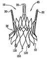
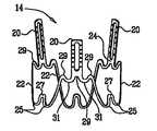
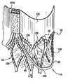
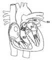
본 발명의 양태에 있어서, 본래의 협착된 판막을 치료하기 위한 대동맥 판막은 본래의 판막 복합체를 그의 대동맥(하강류) 및 좌심실(상승류) 측부로부터 축방향으로 개재하도록 배열되는 2개의 부분, 및 수축 도중에는 개방되고 확장 도중에는 폐쇄되도록 배열되는 접을 수 있는 판막(collapsible valve)을 포함한다. 상기 2개의 부분은 전형적으로 근위(즉, 상승류)의 고정 부재로서 기능하는 접을 수 있는 내부 지지체 구조물, 및 원위(즉, 하강류) 고정 부재로서 기능하는 접을 수 있는 외부 지지체 구조물을 포함한다. 원위 고정 부재는 대상의 오름 대동맥에 위치되고 대상의 좌심실 쪽으로 향하는 제 1 축력을 본래 판막 복합체의 대동맥 측부에 적용하도록 배열된다. 근위 고정 부재는 전형적으로는 적어도 부분적으로 좌심실 유출 트랙(LVOT)으로 연장하는 적어도 부분적으로 대동맥 판막의 좌심실 측부에 위치되고 하강류 방향으로(즉, 오름 대동맥쪽으로) 향하는 제 2 축력을 대동맥 고리의 좌심실 측부에(전형적으로는, 좌심실의 상부에) 적용하도록 배열된다. 제 1 및 제 2 축력의 적용은 보형물을 본래의 판막에 커플링한다.In an embodiment of the invention, the aortic valve for treating the original stenosis valve is comprised of two parts arranged to interpose the original valve complex axially from its aortic (downstream) and left ventricular (upward) sides, and And a collapsible valve arranged to open during contraction and close during expansion. The two parts typically comprise a collapsible inner support structure that functions as a proximal (ie, upflow) securing member, and a collapsible outer support structure that serves as a distal (ie, downflow) securing member. The distal fixation member is arranged to apply a first axial force to the aortic side of the original valve complex that is located in the subject's ascending aorta and directed toward the subject's left ventricle. The proximal fixation member is typically located at least partially on the left ventricular side of the aortic valve, at least partially extending to the left ventricular outflow track (LVOT), and has a second axial force directed in the downstream direction (ie, towards the ascending aorta) to the left ventricle of the aortic annulus. Arranged to apply to the side (typically, at the top of the left ventricle). Application of the first and second axial forces couples the implant to the original valve.
본 발명의 일부 양태에 있어서, 판막 보형물은 본래의 폐 판막을 치료하도록 배열된다.In some aspects of the invention, the valve prosthesis is arranged to treat the original pulmonary valve.
일부 적용에 있어서, 원위 고정 부재는 적어도 부분적으로는 대동맥굴(aortic sinuses) 내에서 본래의 고리에 대해 원위 위치되도록 배열되는 체결 아암(engagement arm)을 정의하도록 형상화되고, 일부 적용에 있어서는 제 1 축력을 적용하도록 형상화된다. 전형적으로, 이들 적용을 위해서 원위 고정 부재는 제 1 축력을 대동맥굴의 저부에 적용하도록 배열된다.In some applications, the distal fixation member is shaped to define an engagement arm that is arranged at least partially distal to the original ring within the aortic sinuses, and in some applications the first axial force It is shaped to apply. Typically, for these applications the distal fixation member is arranged to apply the first axial force to the bottom of the aortic oyster.
판막 보형물은 혈관내 또는 치근끝경유(transapical) 접근법과 같은 최소 침투 접근법을 이용하여 본래 협착 판막에 위치되도록 배열된다. 판막 보형물은 자기-팽창되고 배치가 용이하도록 배열되며, 전형적으로는 제자리에 고정시키는 접합을 필요로 하지 않는다. 본래의 판막 첨판은 전형적으로는 가능한한 최대로 개방되는 것을 필요로 하지 않지만, 전형적으로 약 15 내지 20㎜의 직경인 판막 보형물의 좁은 부분의 삽입을 허용하는 정도에 불과하다. 따라서 판막 보형물의 배치는 다수의 통상적인 판막 보형물 이식 과정에 비해서 판막 및 관상동맥교합으로부터 제거된 석회화 또는 혈전 물질의 대사의 리스크를 감소시킨다.The valve prosthesis is arranged to be placed in the original stenosis valve using a minimally invasive approach, such as an intravascular or transapical approach. Valve prostheses are self-expansive and arranged to facilitate placement, and typically do not require bonding to hold them in place. The original valve leaflets typically do not need to be opened to the fullest extent possible, but only to allow insertion of narrow portions of the valve prostheses, typically about 15 to 20 mm in diameter. Thus, placement of the valve prosthesis reduces the risk of metabolism of calcification or thrombotic material removed from the valve and coronary artery occlusion compared to many conventional valve prosthesis implantation procedures.
당해 기술분야에 알려진 일부 판막 보형물과는 달리, 본 발명의 일부 양태의 판막 보형물은 본래 판막에 대해 바깥쪽으로 방사상 적용된 큰 힘에 대한 고정을 담보하지 않는다. 전형적으로, (b) 본래 판막에 대한 판막 보형물에 의해 바깥쪽으로 적용된 배분력(radial force)에 대한 (a) 판막 보형물에 의해 적용된 제 1 또는 제 2 축력의 비는 1.5 초과 : 1, 예를 들어 3 초과 : 1, 또는 6 초과 : 1이다. 일부 적용에 있어서 판막 보형물은 본래 판막에 대해 바깥쪽으로 0.5 lb(0.23 ㎏f) 미만, 예를 들어 0.3 lb(0.14 ㎏f) 미만, 또는 0.1 lb(0.045 ㎏f) 미만의 배분력을 적용한다. 일부 적용에 있어서, 판막 보형물은 확장 도중에는 40g 이상의 힘으로 제 1 축력을, 그리고 수축 도중에는 1g 이상(예를 들어 5g 이상)의 힘으로 제 2 축력을 적용하도록 배열된다. 일부 적용에 있어서, 판막 보형물은 확장 도중에 1,700g 이하의 힘으로 제 1 축력을 적용하도록 배열된다.Unlike some valve prostheses known in the art, the valve prostheses of some embodiments of the present invention do not secure a fixation against large forces radially applied outward relative to the original valve. Typically, (b) the ratio of the first or second axial force applied by the (a) valve implant to the radial force applied outward by the valve implant to the original valve is greater than 1.5: 1, for example Greater than 3: 1, or greater than 6: 1. In some applications the valve prosthesis applies a distribution force less than 0.5 lb (0.23 kgf), eg less than 0.3 lb (0.14 kgf), or less than 0.1 lb (0.045 kgf) outward relative to the original valve. In some applications, the valve prosthesis is arranged to apply the first axial force with a force of 40 g or more during expansion and the second axial force with a force of 1 g or more (eg, 5 g or more) during contraction. In some applications, the valve prosthesis is arranged to apply the first axial force with a force of 1,700 g or less during expansion.
다른 양태에 있어서, 판막 보형물은 보형물의 고정을 돕기에 충분하거나 또는 보형물을 고정시키기에 충분한 힘을 본래의 판막에 대해 바깥쪽 방사상으로 적용한다.In another embodiment, the valve prosthesis applies a force radially outward relative to the original valve that is sufficient to aid in the fixation of the implant or to secure the implant.
본 발명의 일부 양태에 있어서, 판막 보형물은 본래 판막을 통해 보형물을 삽입시키는데 필요하지만 본래 첨판을 가능한한 최대 정도로 완전히 개방하기에는 불충분한 정도로만 바깥쪽 배분력을 적용한다. 전형적으로는 본래 판막 첨판의 대동맥 측부에 위치된 원위 고정 부재와 연계한 상기 수준의 배분력 적용은 관상틀맥소공(coronary ostia)에 대한 본래 판막 첨판의 밀림을 방지한다. 추가적으로, 판막 보형물의 배열은 일반적으로는 본래 첨판의 손상을 방지함으로써 인공 판막 주위의 누출을 감소시키거나 또는 제거시킨다. 판막 보형물이 본래 첨판을 원전히 개방하지 않거나, 포개지 않거나 크림핑하지 않기 때문에 상기 손상이 방지된다. 대신에, 판막 보형물은 원위 고정 부재(예를 들어 그의 체결 아암)와 근위 고정부재 사이에 첨판을 서서히(gently) 봉합한다. 또한, 전형적으로는 판막 보형물이 본래 판막 연결부에 실질적인 축력을 적용하지 않기 때문에 상기 본래 첨판의 손상이 방지된다. 또한, 판막 보형물이 후술하는 바와 같은 불룩한 근위 스커트를 포함하는 적용에 있어서, 상기 스커트는 일반적으로는 인공 판막 주위의 누출 감소를 돕는다.In some aspects of the invention, the valve prosthesis applies lateral distribution force only to the extent necessary to insert the implant through the valve but inadequate to fully open the leaflet to the fullest extent possible. This level of force application, typically associated with the distal fixation member located on the aortic side of the original valve leaflet, prevents the rolling of the original valve leaflet against the coronary ostia. In addition, the arrangement of the valve prostheses generally reduces or eliminates leakage around the artificial valve by preventing damage to the original leaflet. The damage is prevented because the valve prosthesis does not originally open, superimpose or crimp the leaflets. Instead, the valve implant gently seals the leaflet between the distal fixation member (eg its fastening arm) and the proximal fixation member. In addition, damage to the original leaflet is typically prevented because the valve implant does not apply substantial axial force to the original valve connection. In addition, in applications where the valve prosthesis includes a bulging proximal skirt as described below, the skirt generally helps to reduce leakage around the artificial valve.
전형적으로, 판막 보형물은 첨판의 길이를 축소시키거나, 또는 첨판을 굽히거나, 크림핑하거나, 또는 포개는 본래 판막 첨판의 선단에 축력을 적용하지 않는다. 첨판의 복합 조성(섬유 조직, 연질 죽종 및 석회화)이 주어지는 경우 그러한 압착(compression)은 물질을 제거하거 대사를 유발하는 전단력을 첨판에 적용시켜야 한다.Typically, valve prostheses reduce the length of the leaflet, or the leaflet is bent, crimped, or overlapped without applying axial force to the tip of the original valve leaflet. Given the complex composition of the leaflets (fibrous tissue, soft atherosclerosis and calcification), such compression must apply shear forces to remove material or to induce metabolism.
본원에서 판막 보형물은 일반적으로 본래 대동맥 판막을 치료하는 것과 관련하여 기술되었지만 일부 양태에서 판막 보형물은 판막 보형물에 대한 적절한 변형으로 본래 폐 판막(즉, 심장에서 기타 반달 판막), 또는 몸체의 또다른 본래 판막을 치료하는데 사용된다.Valve implants are generally described herein in connection with treating the original aortic valve, but in some embodiments valve implants may be modified with the original lung valve (ie, other half-moon valves in the heart), or another intact body of the body, with appropriate modifications to the valve implant. Used to treat valves.
특허청구범위를 비롯한 본원에서 사용되는 "본래 판막 복합체"는 본래 반달 판막 첨판, 판막의 고리, 심실 측부 상의 판막밑 조직, 및 반달 고리의 아래 절반을 포함한다.As used herein, including in the claims, the “original valve complex” originally includes a half moon valve leaflet, a ring of valves, subvalve tissue on the ventricular side, and a lower half of the half moon ring.
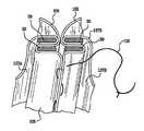
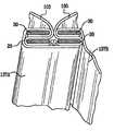
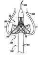
본 발명의 한 양태에 따라 대상의 본래 판막 복합체의 본래 반달 판막에 이식하기 위한 보형물을 포함한 장치가 제공되며, 상기 보형물은, 확장 도중에는 보형물의 종축쪽 안으로 접을 수 있고 수축 도중에는 바깥쪽으로 개방하도록 배열된 플라이언트 물질(pliant material)을 포함하는 인공 원위 판막; 오름 대동맥 및 폐동맥으로 구성된 군으로부터 선택된 대상의 하강류 동맥에 위치되도록 배열된 원위 고정 부재; 및 원위 고정 부재에 커플링되고, 적어도 부분적으로는 본래 반달 판막의 심실 측부에 위치되도록 배열되며, 판막의 플라이언트 물질에 커플링되고 종축으로부터 바깥쪽으로 분기하는 매개부(intermediary portion) 및 매개부에 대해 원위에 있고 격자의 매개부로부터 바깥쪽으로 분기하는 원위부를 정의하도록 형상화되는 격자를 정의하도록 형상화된 근위 고정 부재를 포함한다.In accordance with an aspect of the present invention there is provided an apparatus comprising a implant for implantation into an original half-moon valve of an original valve complex of a subject, the implant being arranged to fold into the longitudinal axis of the implant during expansion and to open outward during contraction. Artificial distal valve including pliant material; A distal fixation member arranged to be located in a descending artery of a subject selected from the group consisting of an ascending aorta and a pulmonary artery; And an intermediary portion and intermediate portion coupled to the distal fixation member, at least partially arranged to be located at the ventricular side of the original half-moon valve, coupled to the valve material of the valve and branching outward from the longitudinal axis. And a proximal fixation member shaped to define a grating distal to and shaped to define a distal portion branching outwardly from the media of the grating.
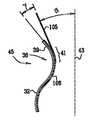
일부 적용에 있어서, 스커트의 매개부와 원위부 사이의 분기각은 5°이상이다. 일부 적용에 있어서, 스커트의 매개부와 종축 사이의 분기각은 3°이상이다.In some applications, the angle of divergence between the medial and distal portions of the skirt is at least 5 °. In some applications, the divergence angle between the medial portion of the skirt and the longitudinal axis is at least 3 °.
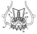
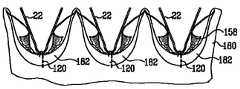
일부 적용에 있어서, 본래 판막 복합체는 반달굴(semilunar sinus)을 가지며; 원위 고정 부재는, 적어도 부분적으로는 반달굴 각각의 것 내부에 위치되도록 배열되는 복수의 근위 체결 아암을 정의하고, 조합시 반달굴을 정의하는 조직에 대상의 심실쪽을 향하는 제 1 축력을 적용하도록 형상화되고; 격자의 근위부는, 제 1 및 제 2 축력의 적용이 본래 판막 복합체에 보형물을 커플링하도록 본래 판막의 심실 측부에 하강류 동맥쪽으로 향하는 제 2 축력을 적용하도록 배열된다.In some applications, the original valve complex has semilunar sinus; The distal fixation member defines a plurality of proximal fastening arms that are arranged to be positioned at least partially within each of the half moons, and in combination to apply a first axial force directed to the ventricular side of the subject to the tissue defining the half moons. Shaped; The proximal portion of the grating is arranged to apply a second axial force directed towards the descending artery on the ventricular side of the original valve such that the application of the first and second axial force couples the implant to the original valve composite.
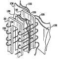
일부 적용에 있어서, 원위 고정 부재는 내부 지지체 구조물을 포함하고, 근위 고정 부재는 부분적으로는 내부 지지체 구조물 위로 위치되는 외부 지지체 구조물을 포함한다. 일부 적용에 있어서, 내부 지지체 구조물은 보형물 원위 판막의 플라이언트 물질에 커플링되는 복수의 원위 분기 내부 지주를 정의하도록 형상화된다.In some applications, the distal fixation member includes an inner support structure, and the proximal fixation member includes an outer support structure that is partially positioned over the inner support structure. In some applications, the inner support structure is shaped to define a plurality of distal branched internal struts coupled to the implant material of the prosthetic distal valve.
본 발명의 한 양태에 따라 추가적으로 대상의 본래 판막 복합체의 본래 반달 판막에 이식하기 위한 보형물을 포함하는 장치가 제공되며, 상기 보형물은, 오름 대동맥 및 폐동맥으로 구성된 군으로부터 선택된 대상의 하강류 동맥에 위치되도록 배열된 원위 고정 부재; 원위 고정 부재에 커플링되고, 적어도 부분적으로는 본래 반달 판막의 심실 측부에 위치되도록 배열되며, 내부 표면을 갖는 격자를 정의하도록 배열된 근위 고정 부재; 격자의 내부 표면에 커플링된 이식편 커버링(graft covering); 및 이식편 커버링에 커플링되고 격자에는 직접 커플링되지 않는 플라이언트 물질을 포함하는 인공 원위 판막을 포함한다.According to one aspect of the present invention there is further provided a device comprising a implant for implantation into the original half-moon valve of the original valve complex of the subject, the implant being located in a descending artery of the subject selected from the group consisting of the ascending aorta and the pulmonary artery A distal fixation member arranged to be; A proximal fixation member coupled to the distal fixation member, arranged at least in part to be located at the ventricular side of the half moon valve and arranged to define a grating having an inner surface; Graft covering coupled to the inner surface of the grating; And an artificial distal valve comprising a pliant material coupled to the graft covering and not directly coupled to the grating.
일부 적용에 있어서, 이식편 커버링은 격자의 내부 표면에 봉합되며, 판막의 플라이언트 물질은 이식편 커버링에 봉합된다.In some applications, the graft covering is sealed to the inner surface of the grating and the valve's pliant material is sealed to the graft covering.
일부 적용에 있어서, 격자는 격자 부재를 포함하고, 이식편 커버링은 격자 부재에 커플링된다. 일부 적용에 있어서, 판막의 플라이언트 물질은 격자 부재들 사이에서 이식편 커버링에 커플링되며 격자 부재들에는 커플링되지 않는다.In some applications, the grating includes a grating member and the graft covering is coupled to the grating member. In some applications, the valve's pliant material is coupled to the graft covering between the grating members and not to the grating members.
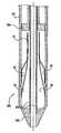
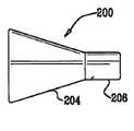
추가적으로, 본 발명의 한 양태에 따라 판막 보형물을 이식하기 위한 전달 카테터를 포함하는 장치가 제공되며, 상기 카테터는, 판막 보형물의 근위부 및 원위부 각각을 유지하도록 배열된 근위 및 원위 전달관; 및 원위 말단으로부터 근위 말단 쪽으로 테이퍼지도록 형상화되고 원위 전달관에 활주가능하게 커플링되는 근위 및 원위 말단를 갖는 요소를 포함하되, 테이퍼진 요소의 원위 말단의 외경은 대략적으로 원위 전달관의 내경과 동일하고, 원위 전달관 및 테이퍼진 요소는, 원위 방향에서 원위 전달관의 진입이 원위 전달관으로부터 판막 보형물의 원위 부분을 해제하고 테이퍼진 요소를 원위 전달관의 근위 말단 근처에 위치시키도록 배열된다.Additionally, in accordance with an aspect of the present invention there is provided an apparatus comprising a delivery catheter for implanting a valve prosthesis, the catheter comprising: proximal and distal delivery vessels arranged to hold proximal and distal portions of the valve prosthesis, respectively; And an element having a proximal and distal end shaped to taper from the distal end to the proximal end and slidably coupled to the distal delivery canal, wherein the outer diameter of the distal end of the tapered element is approximately equal to the inner diameter of the distal delivery canal; The distal delivery tube and the tapered element are arranged such that the entry of the distal delivery tube in the distal direction releases the distal portion of the valve implant from the distal delivery tube and positions the tapered element near the proximal end of the distal delivery tube.
일부 적용에 있어서, 카테터는 원위 전달관에 직접적으로 또는 간접적으로 커플링되는 외부 전달축; 및 외부 전달축 내부에 위치되고 테이퍼진 요소에 고정된 내부 전달축을 포함한다.In some applications, the catheter includes an external delivery shaft coupled directly or indirectly to the distal delivery tube; And an internal transmission shaft located inside the external transmission shaft and fixed to the tapered element.
한 양태에 있어서, 원위 전달관은 원위 전달관의 원위 말단과 테이퍼진 요소의 원위 말단 사이의 원위 전달관 내부에 위치된 스프링을 포함하며, 카테터는, 압착 상태로부터 비압착 상태로의 스프링의 팽창이 원위 방향에서의 원위 전달관의 진입을 유발하도록 배열된다.In one aspect, the distal delivery tube includes a spring located within the distal delivery tube between the distal end of the distal delivery tube and the distal end of the tapered element, wherein the catheter expands the spring from the compressed state to the non-compressed state. It is arranged to cause entry of the distal delivery tube in the distal direction.
일부 적용에 있어서, 카테터는 원위 전달관에 커플링된 가요성 전달축을 포함한다. 일부 적용에 있어서, 테이퍼진 요소는 방사상 압착될 수 있으며, 카테터는 원위 방향에서의 원위 전달관의 진입이 압착 상태로부터 비압착 상태로 테이퍼진 요소를 해제하도록 배열된다. 일부 적용에 있어서 카테터는 원위 전달관의 진입시까지 테이퍼진 요소를 압착 상태로 유지하는 하우징 관을 포함한다.In some applications, the catheter includes a flexible delivery shaft coupled to the distal delivery tube. In some applications, the tapered element may be radially compressed and the catheter is arranged such that the entry of the distal delivery tube in the distal direction releases the tapered element from the compressed state to the non-pressed state. In some applications the catheter includes a housing tube that holds the tapered element in compression until entry of the distal delivery tube.
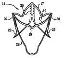
추가적으로, 본 발명의 한 양태에 따라 대상의 본래 판막 복합체의 본래 반달 판막에 이식하기 위한 보형물을 포함하는 장치가 제공되며, 상기 본래 판막 복합체는 3개의 반달굴 및 3개의 본래 연결부를 가지며, 상기 보형물은 3개의 각각의 접합선(juncture)에서 서로 만나는 정확히 3개의 체결 아암을 포함한 지지체 구조물을 포함하는 판막 보형물 지지체를 포함하고, 상기 체결 아암은 3개의 각각의 접합선에서 3개의 피크 복합체, 및 각각 2개의 피크 복합체 사이에 있는 3개의 도랑 복합체(trough complex)를 정의하도록 형상화되고, 보형물의 이식시에 각각의 체결 아암은 적어도 부분적으로는, 각각의 피크 복합체가 본래 연결부 각각의 것과 회전 정렬로 및 회전 정렬에서 원위 배치되도록 반달굴 각각의 것 내부에 배치되고, 각각의 도랑 복합체는 적어도 부분적으로는 반달굴 각각의 것 내부에 배치된다.Additionally, in accordance with an aspect of the present invention there is provided an apparatus comprising a implant for implantation into an original half moon valve of a subject's original valve complex, wherein the original valve complex has three half moons and three original connections. Is a valve prosthesis support comprising a support structure comprising exactly three fastening arms that meet each other at three respective junctions, the fastening arms comprising three peak complexes at three respective junctions, and two each Shaped to define three trough complexes between the peak complexes, each implantation arm upon implantation of the prosthesis is at least partially wherein each peak complex is in rotational alignment and rotational alignment with each of the original connections. Are disposed inside each of the half moon oysters so that they are distal from Separately, they are placed inside each of the half moon caves.
한 양태에 있어서, 본래 반달 판막은 대상의 본래 대동맥 판막을 포함하고, 반달굴은 각각의 대동맥굴을 포함하고, 보형물의 이식시에 각각의 체결 아암은 적어도 부분적으로는 대동맥굴 각각의 것 내부에 배치된다.In one embodiment, the original vandal valve comprises the subject's original aortic valve, the vandal lug comprises each aortic cavern, and upon implantation, each fastening arm is at least partially within each of the aortic cavern. Is placed.
한 양태에 있어서, 본래 반달 판막은 대상의 본래 폐 판막을 포함하고, 반달굴은 각각의 폐굴(pulmonary sinus)을 포함하며, 보형물의 이식시에 각각의 체결 아암은 적어도 부분적으로는 폐굴 각각의 것 내부에 배치된다.In one embodiment, the original vandal valve comprises the subject's original lung valve, the vandal cave comprises a respective pulmonary sinus, and each fastening arm at least partially at each of the lung caves is implanted in the implant. It is placed inside.
한 양태에 있어서, 체결 아암은, 각각의 피크 복합체가 접합선의 그의 각각의 것에서 정확히 하나의 피크를 포함한다. 한 양태에 있어서, 체결은, 각각의 도랑 복합체가 정확히 하나의 도랑을 포함하도록 형상화된다.In one embodiment, the fastening arm has each peak complex comprising exactly one peak at its respective one of the seams. In one aspect, the fastening is shaped so that each trench composite includes exactly one trench.
일부 적용에 있어서, 체결 아암은 각각의 2개의 피크 복합체 사이에 정확히 하나의 도랑을 정의하도록 형상화된다. 또한, 체결 아암은 각각의 2개의 피크 복합체 사이에 복수의 도랑을 정의하도록 형상화된다.In some applications, the fastening arms are shaped to define exactly one groove between each two peak composites. In addition, the fastening arm is shaped to define a plurality of grooves between each two peak composites.
한 양태에 있어서, 체결 아암은 보형물의 이식시에 각각의 반달굴과 본래 판막 복합체의 각각의 본래 첨판근(leaflet root) 사이의 각각의 전이부(transitions)를 접촉하도록 배열된다.In one aspect, the fastening arms are arranged to contact respective transitions between each half-mantle and each original leaflet root of the original valve complex upon implantation of the implant.
한 양태에 있어서, 보형물은 보형물의 이식 도중에 피크 복합체가 각각의 본래 연결부와 자기-정렬하도록 배열된다.In one aspect, the implant is arranged such that the peak complex self-aligns with each original connection during implantation of the implant.
일부 적용에 있어서, 보형물의 이식시에 각각의 피크 복합체는 회전 오프셋(rotational offset)을 갖는 본래 연결부 각각의 것과 회전 정렬로 배치된다. 또한, 보형물의 이식시에, 각각의 피크 복합체는 회전 오프셋 없이 본래 연결부 각각의 것과 회전 정렬로 배치된다.In some applications, upon implantation of the implant, each peak complex is placed in rotational alignment with each of the original connections with rotational offset. In addition, upon implantation of the implant, each peak complex is placed in rotational alignment with each of the original connections without rotational offset.
한 양태에 있어서, 보형물의 이식시에 판막 보형물 지지체는 본래 반달 판막의 본래 연결부에 압축하지 않는다. 또한, 보형물의 이식시에 피크 복합체는 체결 아암의 각각의 접합선에서 본래 반달 판막의 각각의 본래 연결부를 접촉한다.In one embodiment, at implantation of the implant, the valve prosthesis support does not compress originally to the original connection of the half moon valve. In addition, upon implantation of the prosthesis, the peak complex contacts each original connection of the original vandal valve at each junction of the fastening arm.
일부 적용에 있어서, 보형물은 본래 반달 판막에 대해 바깥쪽으로 0.5 lb 미만의 배분력을 적용하도록 배열된다.In some applications, the prosthesis is arranged to apply a distribution force of less than 0.5 lb outward relative to the original half moon valve.
한 양태에 있어서, 보형물은, 본래 반달 판막에 대해 바깥쪽으로 보형물에 의해서 적용된 배분력이 정상적인 심장 동작 조건하에서 본래 판막 복합체에 대해 보형물을 장기간 제자리에 스스로 유지하는 것이 불충분하도록 배열된다. 한 양태에 있어서, 보형물은 이식시에 스퀴징(squeezing) 없이 본래 반달 판막의 첨판을 둘러싸도록, 예를 들어 서서히 둘러싸도록 배열된다.In one embodiment, the implant is arranged such that the distribution force applied by the implant outward relative to the original vandal valve is insufficient to keep the implant in place for itself for a prolonged period of time with respect to the original valve complex under normal cardiac operating conditions. In one embodiment, the prosthesis is arranged to surround, for example, the leaflets of the original half-moon valve without squeezing upon implantation.
일부 적용에 있어서, 보형물은 그의 이식시에 체결 아암이 첨판의 원위 측부에 대략적으로 평행하면서 체결 아암이 본래 반달 판막의 첨판의 원위 측부에 힘을 적용하도록 배열된다.In some applications, the prosthesis is arranged such that the fastening arm applies force to the distal side of the leaflet of the original vandal valve while the fastening arm is approximately parallel to the distal side of the leaflet upon implantation.
한 양태에 있어서, 판막 보형물 지지체는, 보형물의 이식시에 판막 보형물 지지체가 본래 반달 판막의 첨판 위로 포개지지 않도록 배열된다. 한 양태에 있어서, 판막 보형물 지지체는 보형물의 이식시에 판막 보형물 지지체가 본래 판막 복합체의 각각의 반달굴 저부쪽으로 본래 반달 판막의 첨판을 밀어내지 않도록 배열된다. 한 양태에 있어서, 보형물은, 보형물이 본래 판막 복합체에 이식될 때 본래 판막 복합체의 첨판을 충분한 것 미만으로 개방하도록 배열된다. 한 양태에 있어서, 판막 보형물 지지체는 보형물의 이식시에 반달굴 내부에서 본래 반달 판막의 첨판을 상승시키도록 배열된다.In one aspect, the valve prosthesis support is arranged such that upon implantation of the prosthesis, the valve prosthesis support does not naturally overlie the leaflet of the half moon valve. In one embodiment, the valve prosthesis support is arranged such that upon implantation of the prosthesis, the valve prosthesis support does not push the leaflet of the original vandal valve toward the bottom of each half of the original valve complex. In one embodiment, the prosthesis is arranged to open the leaflet of the original valve complex below sufficient when the implant is implanted in the original valve complex. In one aspect, the valve prosthesis support is arranged to elevate the leaflet of the original vandal valve within the half denture upon implantation of the implant.
한 양태에 있어서, 보형물은, 본래 판막 복합체에 이식할 때 체결 아암이 반달굴 각각의 것과 회전에 의해서 정렬되도록 배열된다.In one embodiment, the prosthesis is arranged such that when implanted into the original valve complex, the fastening arms are aligned with rotation of each of the half moon oysters.
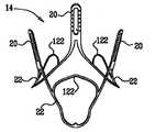
한 양태에 있어서, 각각의 체결 아암은 하나 이상의 연장 아암이 보형물의 이식시에 반달굴 각각의 것의 굴 저부를 체결하도록 배열되는 체결 아암으로부터 연장하는 하나 이상의 연장 요소를 포함한다.In one aspect, each fastening arm includes one or more extension elements extending from the fastening arms, wherein the one or more extension arms are arranged to fasten the oyster bottom of each of the half moon oysters upon implantation of the implant.
한 양태에 있어서, 각각의 체결 아암은 보형물의 이식시에 반달굴 각각의 것을 체결하도록 배열된다. 일부 적용에 있어서, 각각의 체결 아암은 보형물의 이식시에 반달굴 각각의 것을 견고하게 체결하도록 배열된다.In one aspect, each fastening arm is arranged to fasten each of the half moon oysters upon implantation of the implant. In some applications, each fastening arm is arranged to firmly fasten each of the half moon oysters upon implantation of the implant.
한 양태에 있어서, 판막 보형물 지지체는 보형물을 제자리에 유지하기에 충분한 본래 반달 판막의 첨판에 힘을 적용하지 않도록 배열된다.In one embodiment, the valve prosthesis support is arranged such that no force is applied to the leaflets of the original half-moon valve that are sufficient to hold the implant in place.
일부 적용에 있어서, 각각의 체결 아암은 체결 아암으로부터 연장하는 하나 이상의 연장 요소를 정의하도록 형상화되고, 각가의 체결 아암 및 그의 하나 이상의 연장 요소 각각은 체결 아암이 보형물의 이식시에 하나 이상의 연장 요소를 통해 반달굴 각각의 것의 굴 저부를 체결하도록 배열된다.In some applications, each fastening arm is shaped to define one or more extension elements extending from the fastening arm, each of the fastening arms and each of the one or more extension elements thereof having one or more extension elements upon implantation of the implant. Through the oyster bottom of each one is arranged to fasten.
일부 적용에 있어서, 각각의 체결 아암은, (a) 하나 이상의 접합선과 (b) 보형물의 이식시에 반달굴 각각의 것의 굴 저부와 접합선에서 만나는 체결 아암 중의 하나의 접촉점 사이의 보형물의 종축에 평행한 6㎜ 초과인 길이를 정의하도록 형상화된다.In some applications, each fastening arm is parallel to the longitudinal axis of the implant between (a) one or more seams and (b) the contact point of one of the fastening arms that meets at the junction of the oyster bottom of each of the half moon oysters at the time of implantation. It is shaped to define a length greater than one 6 mm.
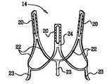
한 양태에 있어서, 보형물은 하나 이상의 인공 첨판을 포함한 인공 판막을 포함하고, 각각의 인공 첨판의 적어도 일부분은 확장 도중에는 폐쇄 위치를 그리고 수축 도중에는 개방 위치를 취하도록 배열되고, 적어도 일부분은 체결 아암의 어느 것과도 직접 체결되지 않는다. 일부 적용에 있어서, 보형물 판막은, 보형물의 이식시에 인공 첨판의 축 길이의 50% 이상이 본래 반달 판막의 본래 판막 첨판에 원위에 있도록 지지체 구조물에 커플링된다. 일부 적용에 있어서, 인공 판막은 개방 및 폐쇄 위치를 취하도록 배열된 접을 수 있는 플라이언트 물질을 포함한다. 일부 적용에 있어서, 판막 보형물 지지체 및 보형물 판막은 판막 보형물 지지체 및 인공 판막을 통해 단일 유동장을 정의하도록 배열된다. 또한, 판막 보형물 지지체 및 인공 판막은 판막 보형물 지지체 및 인공 판막을 통해 복수의 유동장을 정의하도록 배열된다.In one aspect, the prosthesis comprises an artificial valve comprising one or more artificial leaflets, wherein at least a portion of each artificial leaflet is arranged to take a closed position during expansion and an open position during contraction, and at least a portion of the fastening arm It is not directly coupled with either. In some applications, the prosthetic valve is coupled to the support structure such that at implantation of the prosthesis, at least 50% of the axial length of the artificial leaflet is distal to the original valve leaflet of the original vandal valve. In some applications, the artificial valve includes a collapsible pliant material arranged to take open and closed positions. In some applications, the valve implant support and the implant valve are arranged to define a single flow field through the valve implant support and the artificial valve. In addition, the valve prosthesis support and the artificial valve are arranged to define a plurality of flow fields through the valve prosthesis support and the artificial valve.
한 양태에 있어서, 지지체 구조물은, 체결 아암의 접합선이 각각 부착되는 정확히 3개의 연결 포스트를 포함한다. 일부 적용에 있어서, 보형물의 이식시에 연결 포스트는 본래 연결부 각각의 것과 회전 정렬된다.In one aspect, the support structure comprises exactly three connecting posts to which the seam of the fastening arms is respectively attached. In some applications, upon implantation of the implant, the connecting posts are rotationally aligned with each of the original connections.
한 양태에 있어서, 체결 아암은 보형물의 중심축에 대해 옆으로 각지게 돌출(flare out)하도록 형상화된다. 한 양태에 있어서, 체결 아암은 체결 아암이 돌출될 때 본래 판막 복합체의 반달근(semjilunar root)의 형상에 순응한다. 한 양태에 있어서, 체결 아암은 측부 바깥쪽으로 굽어지도록 형상화된다. 한 양태에 있어서, 하나 이상의 체결 아암은 일반적으로는 함수식 z"(r)>=0[여기서, z는 보형물의 종축에 따라 측정한 하나 이상의 체결 아암 상에 주어진 점의 높이이고, r은 종축으로부터 주어진 점 까지의 거리이다]에 의해서 특징지워진다. 일부 적용에 있어서, 형상은 일반적으로는 함수식 z"(r)>0에 의해서 특징지워진다.In one aspect, the fastening arm is shaped to flare out laterally with respect to the central axis of the implant. In one aspect, the fastening arm conforms to the shape of the semjilunar root of the original valve complex when the fastening arm protrudes. In one aspect, the fastening arms are shaped to bend outwards. In one embodiment, the one or more fastening arms are generally of the formula z "(r)> = 0 [where z is the height of a given point on the one or more fastening arms measured along the longitudinal axis of the implant, and r is from the longitudinal axis Distance to a given point]. In some applications, the shape is generally characterized by the function z " (r) >
한 양태에 있어서, 지지체 구조물은 원위 고정 부재로서 기능하도록 배열되고, 판막 보형물 지지체는 근위 고정 부재를 포함하며, 근위 고정 부재 및 원위 고정 부재의 체결 아암은 보형물의 이식시에 심실 및 그의 하강류 측부 각각으로부터 본래 판막 복합체를 축방향으로 개재하도록 배열된다.In one aspect, the support structure is arranged to function as a distal fixation member, the valve prosthesis support includes a proximal fixation member, wherein the fastening arms of the proximal fixation member and the distal fixation member are ventricles and their downstream side upon implantation of the implant. From each other are arranged to interpose in axial direction the original valve complex.
한 양태에 있어서, 체결 아암은, 아암이 본래 판막 복합체의 첨판을 예비결정된 원하는 양보다 많이 개방하는 것을 방지하도록 근위 고정 부재가 본래 판막 복합체의 심실 측부에 적어도 부분적으로 위치되기 전에 이식 과정동안 적어도 부분적으로 반달굴 각각의 것 내부에 배치되도록 배열되며, 상기 개방은 근위 고정 부재에 의해 첨판에 적용되는 힘에 의한 것이다.In one embodiment, the fastening arm is at least partially during the implantation process before the proximal fixation member is at least partially positioned on the ventricular side of the original valve complex to prevent the arm from opening the leaflet of the original valve complex more than a predetermined desired amount. Are arranged to be disposed within each of the half moon oysters, the opening being due to the force applied to the leaflet by the proximal fixation member.
한 양태에 있어서, 근위 고정 부재는 보형물의 이식시에 적어도 부분적으로 대상의 심실에 위치되도록 배열된다.In one aspect, the proximal fixation member is arranged to be positioned at least partially in the subject's ventricles upon implantation of the implant.
한 양태에 있어서, 근위 고정 부재는 본래 판막 복합체의 심실 측부에 바브 힘(barb force)을 적용하도록 배열된 하나 이상의 바브(barb)를 정의하도록 형상화된다. 일부 적용에 있어서, 하나 이상의 바브는 본래 판막 복합체의 심실 측부를 관통하도록 배열된다. 또한, 하나 이상의 바브는 조직을 관통함이 없이 본래 판막 복합체의 심실 측부의 조직으로 돌출하도록 배열된다. 한 양태에 있어서, 원위 고정 부재는 하나 이상의 메이팅 바브(mating barb)를 정의하도록 형상화되고, 근위 고정 부재의 하나 이상의 바브는 보형물을 제자리에 유지하기 위해서 하나 이상의 메이팅 바브를 체결하도록 배열된다.In one aspect, the proximal fixation member is originally shaped to define one or more barbs arranged to apply barb force to the ventricular side of the valve composite. In some applications, one or more barbs are arranged to penetrate the ventricular side of the original valve complex. In addition, the one or more barbs are arranged to protrude into the tissue of the ventricular side of the original valve complex without penetrating the tissue. In one aspect, the distal fixation member is shaped to define one or more mating barbs, and the one or more barbs of the proximal fixation member are arranged to engage one or more mating barbs to hold the implant in place.
한 양태에 있어서, 근위 및 원위 고정 부재는 접을 수 있다. 일부 적용에 있어서, 원위 고정 부재는 이식과정 동안 접혀지면서 하강류 동맥에 위치되고, 근위 고정 부재가 적어도 부분적으로 본래 판막 복합체의 심실 측부에 위치되기 전에 팽창되도록 배열되고, 상기 하강류 동맥은 오름 대동맥 및 폐동맥으로 구성된 군으로부터 선택된다. 일부 적용에 있어서, 장치는 오버튜브(overtube) 및 트로카(trocar)로 구성된 군으로부터 선택된 하나 이상의 관을 포함하고, 근위 및 원위 고정 부재는 접혀지면서 선택된 관에 저장되고 선택된 관으로부터 전개될 때 팽창하도록 배열된다.In one aspect, the proximal and distal fixation members are collapsible. In some applications, the distal fixation member is positioned in the descending artery while folded during the implantation process, and is arranged to expand before the proximal fixation member is at least partially positioned in the ventricular side of the original valve complex, the descending artery being an ascending aorta. And pulmonary arteries. In some applications, the device includes one or more tubes selected from the group consisting of overtubes and trocars, the proximal and distal fixation members being folded and stored in the selected tubes and expanded when deployed from the selected tubes. Is arranged to.
한 양태에 있어서, 근위 고정 부재는 내부 지지체 구조물을 포함하고, 원위 고정 부재는 부분적으로 내부 지지체 구조물 위로 위치되는 외부 지지체 구조물을 포함한다. 일부 적용에 있어서, 내부 및 외부 지지체 구조물은 이식과정 동안 서로 커플링되도록 배열된다.In one aspect, the proximal fixation member includes an inner support structure, and the distal fixation member includes an outer support structure that is located partially over the inner support structure. In some applications, the inner and outer support structures are arranged to be coupled to each other during implantation.
한 양태에 있어서, 외부 지지체 구조물은 복수의 원위 분기 지주 지지체를 정의하도록 형상화되고, 그로부터의 체결 아암은 방사상 바깥쪽으로 연장한다. 한 양태에 있어서, 보형물은 본래 판막 복합체에 이식할 때에 지주 지지체가 각각의 본래 연결부와 정렬되도록 배열된다. 한 양태에 있어서, 내부 지지체 구조물은 복수의 원위 분기 내부 지주를 정의하도록 형상화된다.In one aspect, the outer support structure is shaped to define a plurality of distal branch strut supports, from which the fastening arms extend radially outward. In one embodiment, the prosthesis is arranged such that the strut support is aligned with each original connection when implanted into the original valve complex. In one aspect, the inner support structure is shaped to define a plurality of distal branched internal struts.
한 양태에 있어서, 내부 지지체 구조물은 불룩한 근위 스커트를 정의하도록 형상화되며, 그의 근위 부분은 오름 대동맥 및 폐동맥으로 구성된 군으로부터 선택된 하강류 동맥쪽을 향하는 축력을 적용하도록 배열된다. 일부 적용에 있어서, 보형물은 적어도 스커트의 일부분을 커버하도록 이식편 커버링을 포함한다.In one aspect, the inner support structure is shaped to define a bulging proximal skirt, the proximal portion thereof being arranged to apply an axial force directed towards the descending artery selected from the group consisting of the ascending aorta and the pulmonary artery. In some applications, the implant includes a graft covering to cover at least a portion of the skirt.
한 양태에 있어서, 내부 지지체 구조물은 복수의 원위 분기 내부 지주를 정의하도록 형상화되고 스커트는 내부 지주로부터 연장한다.In one aspect, the inner support structure is shaped to define a plurality of distal branch inner struts and the skirt extends from the inner struts.
한 양태에 있어서, 외부 지지체 구조물은 복수의 원위 분기 지주 지지체를 정의하도록 형상화되며, 그로부터의 체결 아암은 방사상 바깥쪽으로 연장하며, 각각의 지주 지지체는 내부 지주 각각의 것 위로 위치된다.In one aspect, the outer support structure is shaped to define a plurality of distal branch strut supports, the fastening arms extending radially outwardly, each strut support positioned above each of the inner struts.
한 양태에 있어서, 체결 아암은 스커트의 일부분 위로 위치된다.In one aspect, the fastening arm is positioned over a portion of the skirt.
한 양태에 있어서, 보형물은 확장 도중에는 폐쇄 위치를 그리고 수축 도중에는 개방 위치를 취하도록 배열된 접을 수 있는 플라이언트 물질을 포함한 판막을 포함하고, 플라이언트 물질은 복수의 세그먼트(segment)를 포함하고, 그의 둘 이상은 지주 지지체 중의 하나 및 내부 지주 각각의 것에 의해서 서로 커플링된다.In one aspect, the prosthesis comprises a valve comprising a collapsible pliant material arranged to take a closed position during expansion and an open position during contraction, the pliant material comprising a plurality of segments, The two or more are coupled to each other by one of the strut supports and each of the inner struts.
추가적으로 본 발명의 한 양태에 따라, 대상의 본래 판막 복합체의 본래 대동맥 판막에 이식하기 위한 보형물을 포함한 장치가 제공되며, 상기 본래 판막 복합체는 정확히 2개의 대동맥굴 및 2개의 본래 연결부를 갖고, 상기 보형물은, 2개의 각각의 접합선에서 서로 만나는 정확히 2개의 체결 아암을 포함한 지지체 구조물을 포함하는 판막 보형물 지지체를 포함하며, 상기 체결 아암은 2개의 각각의 접합선에서 2개의 피크 복합체, 및 피크 복합체들 사이에 있는 2개의 도랑 복합체를 정의하도록 형상화되고, 각각의 체결 아암은 적어도 부분적으로는, 각각의 피크 복합체가 본래 연결부 각각의 것과 회전 정렬로 및 회전 정렬에서 원위 배치되고, 각각의 도랑 복합체가 적어도 부분적으로 대동맥굴 각각의 것 내부에 배치되도록 대동맥굴 각각의 것 내부에 배치된다.Additionally according to one aspect of the present invention there is provided an apparatus comprising a implant for implantation into an original aortic valve of a subject's original valve complex, wherein the original valve complex has exactly two aortic densities and two original connections, the implant Is a valve prosthesis support comprising a support structure comprising exactly two fastening arms meeting each other at two respective seams, the fastening arms being between two peak complexes and two peak complexes at two respective seams. Shaped to define two grooved composites, each fastening arm at least partially disposed with each peak composite distally disposed in rotational and rotational alignment with each of the original connections, and each grooved composite at least partially Inside each of the aortic oysters to be placed inside each of the aortic oysters Is placed.
한 양태에 있어서, 체결 아암은, 각각의 피크 복합체가 접합선 각각의 것에서 정확히 하나의 피크를 포함하도록 형상화된다. 한 양태에 있어서, 체결 아암은 각각의 도랑 복합체가 정확히 하나의 도랑을 포함하도록 형상화된다.In one embodiment, the fastening arms are shaped such that each peak complex includes exactly one peak at each of the seam lines. In one aspect, the fastening arms are shaped such that each trench composite includes exactly one trench.
한 양태에 있어서, 각각의 체결 아암은 보형물의 이식시에 대동맥굴 각각의 것을 체결하도록 배열된다.In one aspect, each fastening arm is arranged to fasten each of the aortic vertebrae upon implantation of the implant.
추가적으로 본 발명의 한 양태에 따라서, 대상의 본래 판막 복합체의 본래 반달 판막에 이식하기 위한 보형물을 포함한 장치가 제공되며, 상기 보형물은 확장 도중에는 폐쇄 위치를 그리고 수축 도중에는 개방 위치를 취하도록 배열된 하나 이상의 인공 첨판을 포함한 인공 판막; 및 인공 첨판의 축 길이의 50% 이상이 본래 반달 판막의 본래 판막 첨판에 대해 원위에 있도록, 인공 판막에 커플링되고 본래 반달 판막 부위의 하나 이상의 반달굴을 체결하도록 배열된 판막 보형물 지지체를 포함한다.Additionally in accordance with an aspect of the present invention there is provided an apparatus comprising a implant for implanting in a native half-moon valve of a subject's original valve complex, wherein the implant is arranged to take a closed position during expansion and an open position during contraction Artificial valves, including artificial leaflets; And a valve prosthesis support coupled to the artificial valve and arranged to engage one or more half moons of the original vandal valve region such that at least 50% of the axial length of the artificial leaf valve is distal to the original valve leaflet of the original vandal valve. .
한 양태에 있어서, 본래 반달 판막은 본래 대동맥 판막을 포함하고, 반달굴은 각각의 대동맥굴을 포함하며, 판막 보형물 지지체는 하나 이상의 대동맥굴을 체결하도록 배열된다. 한 양태에 있어서, 본래 반달 판막은 본래 폐 판막을 포함하고, 반달굴은 각각의 폐굴을 포함하며, 판막 보형물 지지체는 하나 이상의 폐굴을 체결하도록 배열된다.In one embodiment, the original half-moon valve comprises the original aortic valve, the half-moon buckle comprises each aortic buckle, and the valve prosthesis support is arranged to engage one or more aortic buckles. In one embodiment, the original half moon valve comprises the original lung valve, the half moon cave comprises each lung cave, and the valve prosthesis support is arranged to engage one or more lung caves.
추가적으로 본 발명의 한 양태에 따라 대상의, 3개의 반달굴 및 3개의 본래 연결부를 갖는 본래 판막 복합체의 본래 반달 판막에 보형물을 이식하는 방법이 제공되며, 상기 방법은, 판막 보형물 지지체를 포함한 보형물을 제공하는 단계로서, 상기 판막 보형물 지지체는 3개의 각각의 접합선에서 서로 만나는 정확히 3개의 체결 아암을 포함한 지지체 구조물, 및 각각 2개의 피크 복합체 사이에 있는 3개의 도랑 복합체를 포함하되, 상기 체결 아암이 3개의 각각의 접합선에서 3개의 피크 복합체를 정의하도록 형상화되는 것인 단계; 및 각각의 체결 아암이 적어도 부분적으로는 반달굴 각각의 것 내부에 배치되고, 각각의 피크 복합체가 본래 연결부 각각의 것과 회전정렬로 및 회전정렬에서 원위 배치되며, 각각의 도랑 복합체가 적어도 부분적으로는 반달굴 각각의 것 내부에 배치되도록 보형물을 이식하는 단계를 포함한다.Additionally according to one aspect of the present invention there is provided a method of implanting a implant into an original half moon valve of an original valve composite having three vandal oysters and three original connections, the method comprising implanting a implant including a valve implant support. In providing, the valve prosthesis support includes a support structure comprising exactly three fastening arms that meet each other at three respective seam lines, and three gutter complexes, each between two peak complexes, wherein the fastening arm has three Shaped to define three peak complexes at each junction; And each fastening arm is at least partially disposed within each of the half moon oysters, each peak composite distally disposed in rotational alignment and in rotational alignment with each of the original connections, each grooved composite being at least partially Implanting the implant to be disposed within each of the half moon oysters.
한 양태에 있어서, 본래 반달 판막은 대상의 본래 대동맥 판막을 포함하고, 반달굴은 각각의 대동맥굴을 포함하며, 이식은 각각의 체결 아암이 적어도 부분적으로는 대동맥굴 각각의 것 내부에 배치되도록 보형물을 이식하는 것을 포함한다.In one embodiment, the original half moon valve comprises the subject's original aortic valve, the half moon includes each aortic oyster, and the implantation is performed such that each fastening arm is at least partially disposed within each of the aortic oysters. It involves transplanting.
한 양태에 있어서, 본래 반달 판막은 대상의 본래 폐 판막을 포함하며, 반달굴은 각각의 폐굴을 포함하고, 이식은, 각각의 체결 아암이 적어도 부분적으로는 폐굴 각각의 것 내부에 배치되도록 보형물을 이식하는 것을 포함한다.In one embodiment, the original half moon valve comprises the subject's original lung valve, the half moon cave comprises each lung cave, and the transplantation involves implantation of the implant such that each fastening arm is at least partially disposed within each of the lung cave. It involves transplanting.
한 양태에 있어서, 보형물은 보형물의 이식동안 피크 복합체가 각각의 본래 연결부와 자기-정렬하도록 배열된다.In one aspect, the implant is arranged such that the peak complex self-aligns with each original connection during implantation of the implant.
한 양태에 있어서, 이식은, 보형물이 스퀴징 없이 본래 반달 판막의 첨판을 둘러싸도록(embrace), 예를 들어 서서히 둘러싸도록 보형물을 이식하는 것을 포함한다. 한 양태에 있어서, 이식은 판막 보형물 지지체가 본래 반달 판막의 첨판 위로 포개지지 않도록 보형물을 이식하는 것을 포함한다.In one aspect, the implantation includes implanting the implant such that the implant encircles the leaflet of the original half-moon valve without squeezing, eg, slowly. In one embodiment, the implantation comprises implanting the implant such that the valve prosthesis supporter does not nest over the leaflet of the original half moon valve.
한 양태에 있어서, 이식은 체결 아암이 각각의 반달굴 각각의 저부를 접촉하도록 보형물을 이식하는 것을 포함한다.In one aspect, the implantation includes implanting the implant so that the fastening arms contact the bottom of each of the half moon vertebrae.
한 양태에 있어서, 이식은 보형물을 서서히 회전시킴으로써 본래 반달 판막 부위에 대해 보형물을 자기-정렬시키는 것을 포함한다.In one embodiment, the implantation comprises self-aligning the implant with respect to the original vandal valve site by slowly rotating the implant.
한 양태에 있어서, 지지체 구조물은 원위 고정 부재로서 기능하도록 배열되고, 판막 보형물 지지체는 근위 고정 부재를 포함하고, 이식은, 근위 고정 부재 및 원위 고정 부재의 체결 아암이 심실로부터의 본래 판막 복합체 및 그의 하강류 측부 각각을 축방향으로 개재하도록 보형물을 이식하는 것을 포함한다.In one aspect, the support structure is arranged to function as a distal fixation member, the valve prosthesis support comprises a proximal fixation member, and the implantation of the prosthetic fixation member and the distal fixation arm of the distal fixation member from the ventricle and the original valve complex thereof Implanting the prosthesis so as to intersect each of the downstream sides in the axial direction.
한 양태에 있어서 이식은, 원위 고정 부재를 접으면서 원위 고정 부재를 하강류 동맥에 위치시키는 단계; 원위 고정 부재를 팽창시키는 단계; 및 이어서 근위 고정 부재를 본래 판막 복합체의 심실 측부에 적어도 부분적으로 위치시키는 단계로서, 상기 하강류 동맥이 오름 대동맥 및 폐동맥으로 구성된 군으로부터 선택되는 것인 단계를 포함한다.In one aspect the implantation comprises the steps of: positioning the distal fixation member in the downflow artery while folding the distal fixation member; Inflating the distal fixation member; And then positioning the proximal fixation member at least partially on the ventricular side of the original valve complex, wherein the descending artery is selected from the group consisting of an ascending aorta and a pulmonary artery.
한 양태에 있어서, 이식은, 근위 및 원위 고정 부재를 접으면서 오버튜브 및 트로카로 구성된 군으로부터 선택된 하나 이상의 관에 근위 및 원위 고정 부재를 저장하는 단계; 및 근위 및 원위 고정 부재가 팽창하도록 선택된 관으로부터 근위 및 원위 고정 부재를 전개하는 단계를 포함한다.In one aspect, the implant may comprise storing the proximal and distal fixation members in at least one tube selected from the group consisting of overtubes and trocars while folding the proximal and distal fixation members; And deploying the proximal and distal fixation members from the tube selected to expand the proximal and distal fixation members.
한 양태에 있어서, 근위 고정 부재는 내부 지지체 구조물을 포함하고, 원위 고정 부재는 내부 지지체 구조물 위에 부분적으로 위치되는 외부 지지체 구조물을 포함하며, 이식은 이식도중 내부 및 외부 지지체 구조물을 서로에 대해 배열하는 것을 포함한다.In one aspect, the proximal fixation member includes an inner support structure, the distal fixation member includes an outer support structure that is partially positioned over the inner support structure, and the implantation comprises arranging the inner and outer support structures relative to each other during implantation. It includes.
추가적으로 본 발명의 한 양태에 따라 대상의, 정확히 2개의 대동맥굴 및 2개의 본래 연결부를 갖는 본래 판막 복합체의 본래 대동맥 판막에 보형물을 이식하는 방법이 제공되며, 상기 방법은, 판막 보형물 지지체를 포함한 보형물을 제공하는 단계로서, 상기 판막 보형물 지지체는 2개의 각각의 접합선에서 서로 만나는 정확히 2개의 체결 아암을 포함한 지지체 구조물, 및 각각 피크 복합체 사이에 있는 2개의 도랑 복합체를 포함하되, 상기 체결 아암이 2개의 각각의 접합선에서 2개의 피크 복합체를 정의하도록 형상화되는 것인 단계; 및 각각의 체결 아암이 적어도 부분적으로는 반달굴 각각의 것 내부에 배치되고, 각각의 피크 복합체가 본래 연결부 각각의 것과 회전정렬로 및 회전정렬에서 원위 배치되며, 각각의 도랑 복합체가 적어도 부분적으로는 반달굴 각각의 것 내부에 배치되도록 보형물을 이식하는 단계를 포함한다.Additionally according to one aspect of the present invention there is provided a method of implanting a implant in an original aortic valve of an original valve complex having exactly two aortic dens and two original connections, the method comprising a prosthesis comprising a valve implant support. Wherein the valve prosthesis support comprises a support structure comprising exactly two fastening arms that meet each other at two respective bond lines, and two grooved composites, each between the peak complexes, wherein the fastening arms are two Shaped to define two peak complexes at each junction; And each fastening arm is at least partially disposed within each of the half moon oysters, each peak composite distally disposed in rotational alignment and in rotational alignment with each of the original connections, each grooved composite being at least partially Implanting the implant to be disposed within each of the half moon oysters.
추가적으로 본 발명의 한 양태에 따라 대상의 본래 판막 복합체의 본래 반달 판막에 보형물을 이식하는 방법이 제공되며, 상기 방법은, 확장 도중에는 폐쇄 위치를 그리고 수축 도중에는 개방 위치를 취하도록 배열된 하나 이상의 인공 첨판을 포함한 인공 판막, 및 상기 인공 판막에 커플링된 판막 보형물 지지체를 포함한 보형물을 제공하는 단계; 및 인공 첨판의 축 길이의 50% 이상이 본래 반달 판막의 본래 판막 첨판에 대해 원위에 있도록 판막 보형물 지지체가 본래 반달 판막 부위의 하나 이상의 반달굴을 체결하도록 보형물을 이식하는 단계를 포함한다.Additionally according to one aspect of the present invention there is provided a method of implanting a implant into the original half-moon valve of a subject's original valve complex, the method comprising one or more artificial leaflets arranged to take a closed position during expansion and an open position during contraction Providing a prosthesis including an artificial valve, and a valve prosthesis support coupled to the artificial valve; And implanting the implant such that the valve prosthetic support engages one or more half moons of the original vandal valve region such that at least 50% of the axial length of the artificial leaf valve is distal to the original valve leaflet of the original vandal valve.
한 양태에 있어서, 본래 반달 판막은 본래 대동맥 판막을 포함하고, 보형물을 이식하는 것은, 판막 보형물 지지체가 본래 대동맥 판막의 하나 이상의 반달굴을 체결하도록 보형물을 이식하는 것을 포함한다.In one embodiment, the original half moon valve comprises the original aortic valve and implanting the implant includes implanting the implant such that the valve implant support engages one or more half moons of the original aortic valve.
한 양태에 있어서, 본래 반달 판막은 본래 폐동맥을 포함하고, 보형물을 이식하는 것은, 판막 보형물 지지체가 본래 대동맥 판막의 하나 이상의 반달굴을 체결하도록 보형물을 이식하는 것을 포함한다.In one embodiment, the original vandal valve comprises the original pulmonary artery and implanting the implant includes implanting the implant such that the valve prosthetic support engages one or more half moons of the original aortic valve.
한 양태에 있어서, 보형물을 이식하는 것은, 보형물 첨판이 반달굴을 체결하지 않도록 보형물을 이식하는 것을 포함한다.In one embodiment, implanting the implant includes implanting the implant such that the implant leaflets do not engage the half moon.
한 양태에 있어서, 보형물을 이식하는 것은 보형물을 서서히 회전시킴으로써 보형물을 본래 반달 판막 부위에 대해 자기-정렬시키는 것을 포함한다.In one aspect, implanting the implant includes self-aligning the implant with respect to the original half moon valve site by slowly rotating the implant.
추가적으로 본 발명의 한 양태에 따르면, 본래 반달 판막 부위에 반달 판막 보형물을 위치시키는 단계로서, 상기 보형물은, 확장 도중에는 폐쇄 위치를 그리고 수축 도중에는 개방 위치를 취하도록 배열된 하나 이상의 인공 첨판을 포함한 인공 판막을 포함하는 것인 단계; 및 인공 첨판의 축 길이의 50% 이상이 본래 반달 판막 부위의 본래 반달 판막의 본래 판막 첨판에 대해 원위에 있도록 인공 첨판과는 다른 반달 판막 보형물의 일부분을 본래 반달 판막 부위의 하나 이상의 반달굴과 체결하는 단계를 포함하는 방법이 제공된다.Additionally in accordance with an aspect of the present invention, a step of positioning a half moon valve prosthesis in the original half moon valve region, the prosthesis comprising one or more artificial leaflets arranged to take a closed position during expansion and an open position during contraction. To include; And engaging a portion of the half moon valve implant different from the artificial leaf plate with one or more half moons of the original half moon valve region such that at least 50% of the axial length of the artificial leaf valve is distal to the original valve leaf plate of the original half moon valve region. Provided is a method comprising the steps of:
한 양태에 있어서, 본래 반달 판막 부위는 본래 대동맥 판막 부위를 포함하고, 반달굴은 각각의 대동맥굴을 포함하며, 반달 판막 보형물은 대동맥 판막 보형물을 포함하고, 위치시키는 것은 대동맥 판막 보형물을 본래 대동맥 판막 부위에 위치시키는 것을 포함하며, 체결시키는 것은 대동맥 판막 보형물의 부분을 하나 이상의 대동맥굴과 체결시키는 것을 포함한다.In one embodiment, the original vandal valve site comprises the original aortic valve site, the half moon cave comprises each aortic oyster, the vandal valve implant comprises the aortic valve implant, and positioning the aortic valve implant by the original aortic valve implant. And positioning at the site, wherein fastening includes fastening a portion of the aortic valve implant with one or more aortic dentures.
한 양태에 있어서, 본래 반달 판막 부위는 본래 폐동맥 판막 부위를 포함하고, 반달굴은 각각의 폐동맥굴을 포함하며, 반달 판막 보형물은 폐동맥 판막 보형물을 포함하고, 위치시키는 것은 폐 판막 보형물을 본래 폐 판막 부위에 위치시키는 것을 포함하며, 체결시키는 것은 폐 판막 보형물의 부분을 하나 이상의 폐굴과 체결시키는 것을 포함한다.In one embodiment, the original vandal valve region comprises the original pulmonary valve region, the half lunar cave comprises each pulmonary artery oyster, the vandal valve implant comprises a pulmonary valve implant, and positioning the pulmonary valve implant is the original pulmonary valve. And positioning at the site, and engaging includes engaging a portion of the lung valve prosthesis with one or more lung densities.
한 양태에 있어서, 체결시키는 것은 반달 판막 보형물을 서서히 회전시킴으로써 본래 반달 판막 부위에 대해 반달 판막 보형물을 자기-정렬시키는 것을 포함한다.In one embodiment, the fastening comprises self-aligning the half moon valve implant with respect to the original half moon valve site by slowly rotating the half moon valve implant.
또한, 본 발명의 한 양태에 따라 대상의 본래 판막 복합체의 본래 반달 판막에 이식하기 위한 보형물을 포함하는 장치가 제공되며, 상기 본래 판막 복합체는 반달굴을 가지며, 상기 보형물은 2개 이상의 체결 아암을 포함한 지지체 구조물을 포함하는 판막 보형물 지지체를 포함하고, 보형물의 이식시에 각각의 체결 아암은 적어도 부분적으로는 반달굴 각각의 것 내부에 배치되고, 하나 이상의 체결 아암의 형상은 일반적으로는 함수식 z"(r)>=0[여기서, z는 보형물의 종축에 따라 측정한 하나 이상의 체결 아암 상에 주어진 점의 높이이고, r은 종축으로부터 주어진 점 까지의 거리이다]에 의해서 특징지워진다.Also provided is an apparatus in accordance with an aspect of the present invention comprising an implant for implantation into an original half moon valve of an original valve complex of a subject, wherein the original valve complex has a half lunar stool, the implant having two or more fastening arms. A valve prosthesis support comprising an included support structure, wherein upon implantation each fastening arm is at least partially disposed within each of the half moons, and the shape of the one or more fastening arms is generally functional z " is characterized by (r)> = 0, where z is the height of a given point on at least one fastening arm measured along the longitudinal axis of the implant and r is the distance from the longitudinal axis to the given point.
일부 적용에 있어서, 형상은 일반적으로는 함수식 z"(r)>0에 의해서 특징지워진다.In some applications, the shape is generally characterized by the function z "(r)> 0.
한 양태에 있어서, 본래 반달 판막은 대상의 본래 대동맥 판막을 포함하고, 반달굴은 각각의 대동맥굴을 포함하고, 보형물의 이식시에 각각의 체결 아암은 적어도 부분적으로는 대동맥굴 각각의 것 내부에 배치된다.In one embodiment, the original vandal valve comprises the subject's original aortic valve, the vandal lug comprises each aortic cavern, and upon implantation, each fastening arm is at least partially within each of the aortic cavern. Is placed.
한 양태에 있어서 본래 반달 판막은 대상의 본래 폐 판막을 포함하고, 반달굴은 각각의 폐굴을 포함하며, 보형물의 이식시에 각각의 체결 아암은 적어도 부분적으로는 폐굴 각각의 것 내부에 배치된다.In one embodiment the original half moon valve comprises the subject's original lung valve, the half moon cave includes each lung cave, and upon implantation of the implant, each fastening arm is at least partially disposed within each of the lung caves.
일부 적용에 있어서, 각각의 체결 아암은 체결 아암으로부터 연장하는 하나 이상의 연장 요소를 포함하고, 하나 이상의 연장 요소는 보형물의 이식시에 반달굴 각각의 것의 굴 저부를 체결하도록 배열된다.In some applications, each fastening arm includes one or more extension elements extending from the fastening arms, wherein the one or more extension elements are arranged to fasten the oyster bottom of each of the half moon oysters upon implantation of the implant.
한 양태에 있어서, 지지체 구조물은 정확히 3개의 체결 아암을 포함한다.In one aspect, the support structure comprises exactly three fastening arms.
한 양태에 있어서, 보형물은 그의 이식시에 스퀴징 없이 본래 반달 판막의 첨판을 둘러싸도록, 예를 들어 서서히 둘러싸도록 배열된다. 한 양태에 있어서, 판막 보형물 지지체는 보형물의 이식시에 판막 보형물 지지체가 본래 반달 판막의 첨판 위로 포개지지 않도록 배열된다.In one aspect, the prosthesis is arranged to surround, for example, gradually the leaflet of the original half moon valve without squeezing upon its implantation. In one embodiment, the valve prosthesis support is arranged such that upon implantation of the prosthesis, the valve prosthesis support does not stack over the leaflet of the original half moon valve.
한 양태에 있어서, 지지체 구조물은 원위 고정 부재로서 기능하도록 배열되고, 판막 보형물 지지체는 근위 고정 부재를 포함하며, 원위 고정 부재 및 원위 고정 부재의 체결 아암은 보형물의 이식시에 심실 및 그의 하강류 측부 각각으로부터 본래 판막 복합체를 축방향으로 개재하도록 배열된다.In one aspect, the support structure is arranged to function as a distal fixation member, the valve prosthesis support includes a proximal fixation member, and the fastening arms of the distal fixation member and the distal fixation member have a ventricle and its downstream side upon implantation of the implant. From each other are arranged to interpose in axial direction the original valve complex.
한 양태에 있어서, 각각의 체결 아암은 보형물의 이식시에 반달굴 각각의 것을 체결하도록 배열된다.In one aspect, each fastening arm is arranged to fasten each of the half moon oysters upon implantation of the implant.
일부 적용에 있어서, 각각의 체결 아암은 체결 아암으로부터 연장하는 하나 이상의 연장 요소를 정의하도록 형상화되며, 각각의 체결 아암 및 그의 각각의 하나 이상의 연장 요소는, 체결 아암이 보형물의 이식시에 반달굴 각각의 것의 굴 저부를 하나 이상의 연장 요소를 경유하여 체결하도록 배열된다.In some applications, each fastening arm is shaped to define one or more elongate elements extending from the fastening arm, each fastening arm and each one or more elongating elements thereof each having a half moon upon implantation of the implant. Arranged to fasten the oyster bottom of the via one or more extension elements.
일부 적용에 있어서, 각각의 체결 아암은 (a) 하나 이상의 접합선과 (b) 보형물의 이식시에 반달굴 각각의 것의 굴 저부와 접합선에서 만나는 체결 아암 중의 하나의 접촉점 사이의 보형물의 종축에 평행한 6㎜ 초과인 길이를 정의하도록 형상화된다.In some applications, each fastening arm is parallel to the longitudinal axis of the implant between (a) one or more seams and (b) the contact point of one of the fastening arms that meets at the junction of the oyster bottom of each of the half moon oysters upon implantation of the implant. It is shaped to define a length greater than 6 mm.
한 양태에 있어서, 보형물은 하나 이상의 인공 첨판을 포함한 인공 판막을 포함하고, 각각의 인공 첨판의 적어도 일부분은 확장 도중에는 폐쇄 위치를 그리고 수축 도중에는 개방 위치를 취하도록 배열되고, 적어도 일부분은 체결 아암과 직접 체결되지 않는다. 일부 적용에 있어서, 보형물 판막은, 보형물의 이식시에 인공 첨판의 축 길이의 50% 이상이 본래 반달 판막의 본래 판막 첨판에 대해 원위에 있도록 지지체 구조물에 커플링된다.In one aspect, the implant comprises an artificial valve comprising one or more artificial leaflets, wherein at least a portion of each artificial leaflet is arranged to take a closed position during expansion and an open position during contraction, and at least a portion directly with the fastening arm It is not fastened. In some applications, the prosthetic valve is coupled to the support structure such that at implantation of the prosthesis, at least 50% of the axial length of the artificial leaflet is distal to the original valve leaflet of the original vandal valve.
한 양태에 있어서, 체결 아암은 보형물의 이식시에 각각의 반달굴 각각의 저부를 접촉하도록 배열된다.In one aspect, the fastening arms are arranged to contact the bottom of each of the half moons upon implantation of the implant.
한 양태에 있어서, 체결 아암은 보형물의 이식시에 각각의 반달굴을 견고하게 체결하도록 배열된다.In one aspect, the fastening arms are arranged to firmly fasten each half moon upon implantation of the implant.
추가적으로 본 발명의 한 양태에 따라 대상의 본래 판막 복합체의 본래 반달 판막에 이식하기 위한 보형물을 포함하는 장치가 제공되며, 상기 본래 판막 복합체는 반달굴을 가지며, 상기 보형물은 2개 이상의 체결 아암을 포함한 지지체 구조물을 포함한 판막 보형물 지지체를 포함하고, 보형물의 이식시에 각각의 체결 아암은 적어도 부분적으로는 반달굴 각각의 것 내부에 배치되고, 하나 이상의 체결 아암의 형상은 대략적으로 윗쪽으로 오목하다.Additionally according to one aspect of the present invention there is provided an apparatus comprising a implant for implantation into an original half moon valve of an original valve complex of a subject, wherein the original valve complex has a half moon gul and the implant comprises two or more fastening arms. A valve prosthesis support comprising a support structure, wherein each fastening arm is at least partially disposed inside each of the half moons at the time of implantation, and the shape of the one or more fastening arms is approximately concave upwards.
추가적으로 본 발명의 한 양태에 따라 대상의, 반달굴을 갖는 본래 판막 복합체의 본래 반달 판막에 보형물을 이식하는 방법이 제공되며, 상기 방법은, 판막 보형물 지지체를 포함하는 보형물을 제공하는 단계로서, 상기 판막 보형물 지지체는 2개 이상의 체결 아암을 포함한 지지체 구조물을 포함하고, 하나 이상의 체결 아암의 형상은 일반적으로는 함수식 z"(r)>=0[여기서, z는 보형물의 종축에 따라 측정한 하나 이상의 체결 아암 상에 주어진 점의 높이이고, r은 종축으로부터 주어진 점 까지의 거리이다]에 의해서 특징지워지는 것인 단계; 및 보형물을, 각각의 체결 아암이 적어도 부분적으로 반달굴 각각의 것 내부에 배치되도록 이식하는 단계를 포함한다. Additionally according to one aspect of the present invention there is provided a method of implanting a implant in an original vandal valve of an original valve complex with a half moon oyster, said method comprising providing a implant comprising a valve implant support. The valve prosthesis support comprises a support structure comprising two or more fastening arms, wherein the shape of the one or more fastening arms is generally a function z " (r) > = 0 [where z is one or more measured along the longitudinal axis of the implant The height of a given point on the fastening arm, r is the distance from the longitudinal axis to the given point]; and the implant is disposed within each of the fastening arms, with each fastening arm at least partially Implanting as possible.
한 양태에 있어서, 이식은 각각의 체결 아암이 배열되어 반달굴 각각의 것을 체결하도록 보형물을 이식하는 것을 포함한다.In one aspect, the implantation comprises implanting the implants such that each fastening arm is arranged to fasten each of the half moons.
추가적으로 본 발명의 한 양태에 따라 대상의, 반달굴을 갖는 본래 판막 복합체의 본래 반달 판막에 보형물을 이식하는 방법이 제공되며, 상기 방법은, 판막 보형물 지지체를 포함한 보형물을 제공하는 단계로서, 상기 판막 보형물 지지체는 2개 이상의 체결 아암을 포함한 지지체 구조물을 포함하고, 하나 이상의 체결 아암의 형상이 대략적으로 윗쪽으로 오목한 것인 단계; 및 각각의 체결 아암이 적어도 부분적으로는 반달굴 각각의 것 내부에 배치되도록 보형물을 이식하는 단계를 포함한다. Additionally according to one aspect of the present invention there is provided a method of implanting a implant into an original vandal valve of an original valve complex having a half moon oyster, the method comprising providing a implant comprising a valve implant support, the valve The prosthetic support includes a support structure comprising two or more fastening arms, wherein the shape of the one or more fastening arms is approximately concave upward; And implanting the implant such that each fastening arm is at least partially disposed within each of the half moon oysters.
추가적으로 본 발명의 한 양태에 따르면, 반달 판막 보형물을 제공하는 단계; 및 이미징 기법(imaging technique)을 사용하지 않고 보형물을 이식하는 단계를 포함하는 방법이 제공된다.Additionally in accordance with an aspect of the present invention, there is provided a method comprising providing a half moon valve prosthesis; And implanting the implant without using an imaging technique.
한 양태에 있어서, 반달 판막 보형물을 제공하는 것은 대동맥 판막 보형물을 제공하는 것을 포함한다. 한 양태에 있어서, 반달 판막 보형물을 제공하는 것은 폐 판막 보형물을 제공하는 것을 포함한다.In one aspect, providing a half moon valve implant includes providing an aortic valve implant. In one aspect, providing a half moon valve prosthesis comprises providing a lung valve prosthesis.
한 양태에 있어서, 이식은, 반달 판막 부위에 보형물을 위치시키는 단계; 및 보형물을 서서히 회전시킴으로써 상기 부위에 대해서 보형물을 자기-정렬시키는 것을 포함한다.In one embodiment, the implantation comprises the steps of: positioning the implant at the half moon valve site; And self-aligning the implant with respect to the site by slowly rotating the implant.
한 양태에 있어서, 보형물을 이식하는 것은 접촉 피드백(tactile feedback)에 기초하여 반달 판막 부위에 대해서 보형물의 올바른 회전 배치를 결정하는 것을 포함한다.In one aspect, implanting the implant includes determining the correct rotational placement of the implant relative to the half moon valve site based on tactile feedback.
추가적으로 본 발명의 양태에 따르면, 반달 판막 보형물을 제공하는 단계; 보형물을 대상의 신체에 위치시키는 단계; 및 접촉 피드백에 기초하여 반달 판막 부위에 대해서 보형물의 올바른 회전 배치를 결정하는 단계를 포함하는 방법이 제공된다.Additionally in accordance with an aspect of the present invention, there is provided a method for producing a half moon valve prosthesis; Positioning the implant on the body of the subject; And determining the correct rotational arrangement of the implant relative to the half moon valve site based on the contact feedback.
한 양태에 있어서, 반달 판막 보형물을 제공하는 것은 대동맥 판막 보형물을 제공하는 것을 포함한다. 한 양태에 있어서, 반달 판막 보형물을 제공하는 것은 폐 판막 보형물을 제공하는 것을 포함한다.In one aspect, providing a half moon valve implant includes providing an aortic valve implant. In one aspect, providing a half moon valve prosthesis comprises providing a lung valve prosthesis.
한 양태에 있어서, 보형물을 위치시키는 것은 이미징 기법을 사용하지 않고 보형물을 위치시키는 것을 포함한다.In one aspect, positioning the implant includes positioning the implant without using an imaging technique.
추가적으로 본 발명의 양태에 따르면, 반달 판막 보형물을 본래 반달 판막 부위에 위치시키는 단계; 및 판막 보형물을 서서히 회전시킴으로써 상기 부위에 대해서 보형물을 자기-정렬시키는 단계를 포함하는 방법이 제공된다.Additionally in accordance with an aspect of the present invention, there is provided a method comprising the steps of: positioning a half moon valve implant at an original half moon valve site; And self-aligning the implant with respect to the site by slowly rotating the valve implant.
한 양태에 있어서, 반달 판막 보형물은 대동맥 판막 보형물을 포함하고, 본래 반달 판막 부위는 본래 대동맥 판막 부위를 포함하며, 위치시키는 것은 대동맥 판막 보형물을 본래 대동맥 판막 부위에 위치시키는 것을 포함한다. 한 양태에 있어서, 반달 판막 보형물은 폐 판막 보형물을 포함하고, 본래 반달 판막 부위는 폐 판막 부위를 포함하며, 위치시키는 것은 폐 판막 보형물을 본래 폐 판막 부위에 위치시키는 것을 포함한다.In one embodiment, the half moon valve implant comprises an aortic valve implant, the original half moon valve region comprises an original aortic valve region, and positioning includes placing the aortic valve implant in the original aortic valve region. In one embodiment, the vandal valve prosthesis comprises a pulmonary valve prosthesis, the original vandal valve site comprises a pulmonary valve site, and locating comprises locating the pulmonary valve prosthesis to the original pulmonary valve site.
한 양태에 있어서, 보형물을 자기-정렬시키는 것은, 보형물을 서서히 회전시키면서 하강류 동맥의 축에 대해 정의된 축방향으로 보형물을 동작시키는 것을 포함하되, 상기 하강류 동맥은 오름 대동맥 및 폐동맥으로 구성된 군으로부터 선택된다.In one embodiment, self-aligning the implant includes operating the implant in an axial direction defined relative to the axis of the descending artery while slowly rotating the implant, wherein the descending artery is a group consisting of an ascending aorta and a pulmonary artery. Is selected from.
한 양태에 있어서, 보형물을 서서히 회전시키는 것은 본래 반달 판막 부위와 보형물의 접촉이 회전을 일으키도록 보형물을 근위 방향으로 동작시키는 것을 포함한다.In one aspect, slowly rotating the implant includes operating the implant in the proximal direction such that contact of the implant with the original half-moon valve site causes rotation.
한 양태에 있어서, 보형물을 위치시키고 보형물을 자기-정렬시키는 것은 이미징 기법을 사용하지 않고 보형물을 위치시키고 보형물을 자기-정렬시키는 것을 포함한다.In one aspect, positioning the implant and self-aligning the implant includes positioning the implant and self-aligning the implant without using imaging techniques.
한 양태에 있어서, 보형물을 자기 정렬시키는 것은 보형물이 반달 판막 부위에 대해 보형물을 회전시키는 것을 시도함으로써 반달 판막 부위에 대해 적절히 정렬되는 것을 확인하는 것을 포함한다.In one aspect, self-aligning the implant includes confirming that the implant is properly aligned with respect to the vandal valve site by attempting to rotate the implant about the vandal valve site.
한 양태에 있어서, 보형물은 적어도 부분적으로는 본래 반달 판막 부위의 각각의 반달굴 내부에 위치되도록 배열되는 하나 이상의 근위 체결 아암을 정의하도록 형상화되며, 보형물을 자기-정렬시키는 것은 체결 아암을 각각의 반달굴에 대해서 자기-정렬시키는 것을 포함한다.In one aspect, the implant is shaped to define one or more proximal fastening arms that are at least partially arranged to be positioned inside each half of the half moon valve site, and self-aligning the implant to each fastening arm Self-aligning the oysters.
한 양태에 있어서, 보형물을 서서히 회전시키는 것은 본래 반달 판막 부위의 조직과 하나 이상의 체결 아암의 접촉이 회전을 일으키도록 보형물을 근위 방향에서 동작시키는 것을 포함한다.In one aspect, slowly rotating the implant includes operating the implant in the proximal direction such that contact of the tissue of the half moon valve region with the one or more fastening arms causes rotation.
한 양태에 있어서, 보형물을 자기-정렬시키는 것은 반달 판막 부위에 대해 체결 아암을 회전하는 것을 시도함으로써 체결 아암이 반달 판막 부위에 대해 적절히 위치되는 것을 확인하는 것을 포함한다.In one aspect, self-aligning the implant includes attempting to rotate the fastening arm about the vandal valve site to confirm that the fastening arm is properly positioned relative to the vandal valve site.
또한, 본 발명의 한 양태에 따르면, 하나 이상의 근위 체결 아암을 정의하도록 형상화된 반달 판막 보형물을 본래 반달 판막 부위에 위치시키는 단계; 체결 아암을 적어도 부분적으로 본래 반달 판막 부위의 각각의 반달굴 내부에 위치시키려고 시도하는 단계; 및 체결 아암을 반달 판막 부위에 대해 회전시키려고 시도함으로써 체결 아암이 반달 판막 부위에 대해 적절히 위치되는 것을 확인하는 단계를 포함하는 방법이 제공된다.In addition, according to one aspect of the invention, there is provided a method comprising the steps of: positioning a vandal valve prosthesis originally shaped at a vandal valve site to define one or more proximal engagement arms; Attempting to position the fastening arm at least partially within each half lumen of the original half moon valve region; And attempting to rotate the fastening arm relative to the half moon valve site to ensure that the fastening arm is properly positioned relative to the half moon valve site.
한 양태에 있어서, 반달 판막 보형물은 대동맥 판막 보형물을 포함하고, 본래 반달 판막 부위는 본래 대동맥 판막 부위를 포함하며, 위치시키는 것은 대동맥 판막 보형물을 본래 대동맥 판막 부위에 위치시키는 것을 포함한다.In one embodiment, the half moon valve implant comprises an aortic valve implant, the original half moon valve region comprises an original aortic valve region, and positioning includes placing the aortic valve implant in the original aortic valve region.
한 양태에 있어서, 반달 판막 보형물은 폐 판막 보형물을 포함하고, 본래 판막 부위는 본래 폐 판막 부위를 포함하며, 위치시키는 것은 폐 판막 보형물을 본래 폐 판막 부위를 위치시키는 것을 포함한다.In one embodiment, the vandal valve prosthesis comprises a pulmonary valve prosthesis, the original valve site comprises an original lung valve site, and positioning the lung valve implant comprises locating the lung valve prosthesis.
추가적으로 본 발명의 한 양태에 따라 대상의 본래 판막 복합체의 본래 반달 판막에 이식하기 위한 보형물을 포함하는 장치가 제공되며, 상기 보형물은, 본래 반달 판막에 대한 보형물의 올바른 회전 배치가 접촉 피드백에 기초하여 결정될 수 있도록 배열되는 지지체 구조물을 포함한다.Additionally according to one aspect of the present invention there is provided an apparatus comprising a implant for implantation into an original half-moon valve of an original valve complex of a subject, wherein the implant has a correct rotational arrangement of the implant relative to the original half-moon valve based on contact feedback. And a support structure arranged to be determined.
추가적으로 본 발명의 한 양태에 따라 대상의 본래 판막 복합체의 본래 반달 판막에 이식하기 위한 보형물을 포함하는 장치가 제공되며, 상기 본래 판막 복합체는 반달굴 및 본래 연결부를 갖고, 상기 보형물은, 오름 대동맥 및 폐동맥으로 구성된 군으로부터 선택된 대상의 하강류 동맥에 위치되고, 적어도 부분적으로는 반달굴 각각의 것 내부에 위치되고 조합시 반달굴을 정의하는 조직에 대상의 심실쪽을 향하는 제 1 축력을 적용하도록 배열되는 정확히 3개의 근위 체결 아암을 정의하도록 형상화된 원위 고정 부재; 및 원위 고정 부재에 커플링된 근위 고정 부재로서, 제 1 및 제 2 축력의 적용이 보형물을 본래 판막 복합체에 커플링하도록, 적어도 부분적으로는 본래 반달 판막의 심실에 위치되고, 본래 반달 판막의 심실 측부에 하강류 동맥쪽을 향하는 제 2 축력을 적용하도록 배열된 것인 근위 고정 부재를 포함한다.Additionally according to one aspect of the present invention there is provided an apparatus comprising a implant for implantation into an original half moon valve of a subject's original valve complex, wherein the original valve complex has a half lumbar and an original connection, wherein the implant includes an ascending aorta and Located in the descending artery of the subject selected from the group consisting of pulmonary arteries and arranged to apply a first axial force directed to the ventricular side of the subject to tissues that are located at least partially within each of the meniscus and define the meniscus in combination A distal fixation member shaped to define exactly three proximal engagement arms; And a proximal fixation member coupled to the distal fixation member, wherein the first and second axial forces are at least partially located in the ventricle of the original half-moon valve, so that the application of the first and second axial forces couples the implant to the original valve complex. A proximal fixation member arranged to apply a second axial force directed towards the downflow artery on the side.
한 양태에 있어서, 본래 반달 판막은 본래 대동맥 판막을 포함하고, 하강류 동맥은 오름 대동맥을 포함하며, 반달굴은 각각의 대동맥굴을 포함하고, 원위 고정 부재는 오름 대동맥에 위치되도록 배열되며, 근위 체결 아암은 적어도 부분적으로는 각각의 대동맥굴 내부에 위치되도록 배열된다.In one embodiment, the original half moon valve comprises the original aortic valve, the descending artery comprises the ascending aorta, the half lumbar includes the respective aorta, and the distal fixation member is arranged to be located in the ascending aorta, proximal The fastening arms are arranged to be located at least partially inside each aortic oyster.
한 양태에 있어서, 본래 반달 판막은 본래 폐 판막을 포함하고, 하강류 동맥은 폐동맥을 포함하며, 반달굴은 각각의 폐굴을 포함하고, 원위 고정 부재는 폐동맥에 위치되도록 배열되며, 근위 체결 아암은 적어도 부분적으로는 각각의 폐굴 내부에 위치되도록 배열된다.In one embodiment, the original vandal valve comprises the original pulmonary valve, the descending artery comprises the pulmonary artery, the half moon buckle comprises the respective lung oyster, the distal fixation member is arranged to be located in the pulmonary artery, and the proximal fastening arm is At least partially arranged to be located inside each lung.
한 양태에 있어서, 원위 및 근위 고정 부재는 보형물을 이식할 때 하강류 측부 및 심실 측부로부터 본래 판막 복합체를 축방향으로 개재시킴으로써 보형물을 본래 판막 복합체에 커플링하도록 배열된다.In one aspect, the distal and proximal fixation members are arranged to couple the implant to the original valve complex by interposing the original valve complex axially from the downstream side and the ventricular side when implanting the implant.
한 양태에 있어서, 원위 고정 부재는 보형물을 이식할 때 본래 연결부에 압축되지 않는다.In one aspect, the distal fixation member is not compressed in its original connection when implanting the prosthesis.
한 양태에 있어서, 보형물은 본래 판막에 대해 바깥쪽으로 0.5 lb 미만의 배분력을 적용하도록 배열된다. 한 양태에 있어서, 보형물은 확장 도중에 40g 이상의 힘으로 제 1 축력을 적용하도록 배열된다. 한 양태에 있어서, 보형물은 수축 도중에 1g 이상의 힘으로 제 2 축력을 적용하도록 배열된다.In one embodiment, the prosthesis is arranged to apply a distribution force of less than 0.5 lbs outward relative to the original valve. In one aspect, the implant is arranged to apply the first axial force with a force of at least 40 g during expansion. In one aspect, the implant is arranged to apply the second axial force with a force of at least 1 g during contraction.
한 양태에 있어서, 보형물은, 본래 반달 판막에 대해 바깥쪽으로 보형물에 의해서 적용된 배분력이 정상적인 심장 동작 조건하에서 본래 판막 복합체에 대해 보형물을 장기간 제자리에 스스로 유지하는 것이 불충분하도록 배열된다.In one embodiment, the implant is arranged such that the distribution force applied by the implant outward relative to the original vandal valve is insufficient to keep the implant in place for itself for a prolonged period of time with respect to the original valve complex under normal cardiac operating conditions.
한 양태에 있어서, 보형물은 이식시에 스퀴징 없이 본래 반달 판막의 첨판을 둘러싸도록, 예를 들어 서서히 둘러싸도록 배열된다.In one embodiment, the prosthesis is arranged to, for example, slowly surround the leaflets of the original half moon valve without squeezing upon implantation.
한 양태에 있어서, 근위 고정 부재가 적어도 부분적으로는 본래 판막 복합체의 심실 측부에 위치되기 전의 이식 과정 동안 원위 고정 부재는 하강류 동맥에 위치되도록 배열된다.In one aspect, the distal fixation member is arranged to be positioned in the descending artery during the implantation process before the proximal fixation member is at least partially positioned on the ventricular side of the original valve complex.
한 양태에 있어서, 원위 고정 부재는 보형물의 이식시에 본래 반달 판막의 첨판이 포개지지 않도록 배열된다. 한 양태에 있어서, 원위 고정 부재는 보형물의 이식시에 본래 판막 복합체의 반달굴 저부 쪽 본래 반달 판막의 첨판을 밀어내지 않도록 배열된다.In one embodiment, the distal fixation member is arranged such that the leaflets of the original vandal valves do not overlap upon implantation of the implant. In one embodiment, the distal fixation member is arranged such that upon implantation of the prosthesis, the leaflet of the original half moon valve at the bottom of the half moon oyster of the original valve composite is not pushed out.
한 양태에 있어서, 각각의 근위 체결 아암은 적어도 부분적으로는 반달굴 각각의 것 내부에 위치되도록 배열되는 하나 이상의 도랑을 정의하도록 형상화된다.In one aspect, each proximal fastening arm is shaped to define one or more grooves arranged to be positioned at least partially within each of the half moon.
한 양태에 있어서, 3개의 체결 아암은 3개의 각각의 접합선에서 서로 만나며, 상기 체결 아암은 3개의 각각의 접합선에 3개의 피크 복합체를 그리고 각각 2개의 피크 복합체 사이에 있는 3개의 도랑 복합체를 정의하도록 형상화되고, 상기 보형물의 이식시에 각각의 피크 복합체의 적어도 일부분은 본래 연결부 각각의 것과 회전 정렬로 및 회전 정렬에서 배치되며, 각각의 도랑 복합체는 적어도 부분적으로는 반달굴 각각의 것 내부에 배치된다.In one embodiment, the three fastening arms meet each other at three respective seams, wherein the fastening arms define three peak complexes at three respective seams and three trench composites each between two peak complexes. Shaped, at the time of implantation, at least a portion of each peak complex is disposed in rotational alignment and in rotational alignment with each of the original connections, and each grooved complex is at least partially disposed within each of the half moon oysters. .
한 양태에 있어서, 근위 고정 부재가 적어도 부분적으로는 본래 판막 복합체의 심실 측부에 위치되기 전에 체결 아암은, 체결 아암이 본래 판막 복합체의 첨판이 예비결정된 원하는 양 보다 많이 개방하는 것을 방지하도록 이식 과정 도중 적어도 부분적으로는 반달굴 각각의 것 내부에 위치되도록 배열되며, 상기 개방은 첨판에 대한 근위 고정 부재에 의해 적용된 힘에 의한 것이다.In one embodiment, before the proximal fixation member is at least partially positioned on the ventricular side of the original valve complex, the fastening arm is adapted to prevent the fastening arm from opening more than a predetermined desired amount of leaflets of the original valve complex. It is arranged to be located at least partially inside each of the half moon caves, said opening being due to the force applied by the proximal fixation member against the leaflet.
한 양태에 있어서, 근위 고정 부재는 적어도 부분적으로는 보형물의 이식시에 대상의 심실에 위치되도록 배열된다.In one aspect, the proximal fixation member is arranged to be at least partially positioned in the subject's ventricles upon implantation of the implant.
한 양태에 있어서, 보형물은, (b) 본래 반달 판막에 대해 보형물에 의해 바깥쪽으로 적용된 배분력에 대한 (a) 제 1 축력의 비가 1.5 초과 : 1로 되도록 제 1 축력을 적용하도록 배열된다.In one embodiment, the implant is arranged to apply the first axial force such that (b) the ratio of the first axial force to the distribution force applied outwardly by the implant relative to the original half moon valve is greater than 1.5: 1.
한 양태에 있어서, 보형물은 보형물이 본래 반달 판막 복합체에 이식될 때에 본래 판막 복합체의 첨판을 충분한 것 미만으로 개방하도록 배열된다.In one embodiment, the prosthesis is arranged to open the leaflet of the original valve complex to less than sufficient when the implant is originally implanted in the vandal valve complex.
한 양태에 있어서, 원위 고정 부재는 보형물의 이식시에 반달굴 내부로부터 본래 반달 판막의 첨판을 상승시키도록 배열된다.In one embodiment, the distal fixation member is arranged to raise the leaflet of the original vandal valve from the interior of the lunar vertebra upon implantation of the implant.
한 양태에 있어서, 원위 고정 부재는 제 1 축력을 본래 판막 복합체의 하나 이상의 첨판의 각각의 근(root)에 적용하도록 배열된다. 한 양태에 있어서, 원위 고정 부재는 각각의 반달굴 저부와 본래 판막 복합체의 하나 이상의 첨판 사이의 각각의 전이부에 제 1 축력을 적용하도록 배열된다.In one aspect, the distal fixation member is arranged to apply a first axial force to each root of one or more leaflets of the original valve complex. In one aspect, the distal fixation member is arranged to apply a first axial force to each transition between each half lumbar bottom and one or more leaflets of the original valve complex.
한 양태에 있어서, 보형물은, 상기 비가 3 초과 : 1, 예를 들어 6 초과 : 1로 되도록 제 1 축력을 적용하도록 배열된다.In one embodiment, the implant is arranged to apply a first axial force such that the ratio is greater than 3: 1, for example greater than 6: 1.
한 양태에 있어서, 보형물은, (b) 본래 반달 판막에 대해 보형물에 의해 바깥쪽으로 적용된 배분력에 대한 (a) 제 2 축력의 비가 1.5 초과 : 1, 예를 들어 3 초과 : 1, 예를 들어 6 초과 : 1로 되도록 제 2 축력을 적용하도록 배열된다.In one embodiment, the prosthesis is (b) the ratio of the second axial force to the distribution force applied outwardly by the prosthesis relative to the original half moon valve is greater than 1.5: 1, for example greater than 3: 1, for example Greater than 6: is arranged to apply the second axial force to be one.
한 양태에 있어서, 보형물은 확장 도중에는 폐쇄 위치를 그리고 수축 도중에는 개방 위치를 취하도록 배열된 인공 판막을 포함한다. 한 양태에 있어서, 인공 판막은 개방 및 폐쇄 위치를 취하도록 배열된 접을 수 있는 플라이언트 물질을 포함한다.In one aspect, the prosthesis includes an artificial valve arranged to take a closed position during expansion and an open position during contraction. In one aspect, the prosthetic valve comprises a collapsible pliant material arranged to take open and closed positions.
한 양태에 있어서, 원위 및 근위 고정 부재 및 인공 판막은 원위 및 근위 고정 부재 및 인공 판막을 통해서 단일 유동장을 정의하도록 배열된다. 또한, 원위 및 근위 고정 부재 및 인공 판막은 원위 및 근위 고정 부재 및 인공 판막을 통해서 복수의 유동장을 정의하도록 배열된다.In one aspect, the distal and proximal fixation members and the artificial valve are arranged to define a single flow field through the distal and proximal fixation members and the artificial valve. In addition, the distal and proximal fixation members and the artificial valve are arranged to define a plurality of flow fields through the distal and proximal fixation members and the artificial valve.
한 양태에 있어서, 인공 판막은 하나 이상의 인공 첨판을 포함하고, 인공 판막은, 인공 첨판의 축 길이의 50% 이상이 보형물의 이식시에 본래 반달 판막의 본래 판막 첨판에 대해 원위에 있도록 보형물에 커플링된다.In one embodiment, the prosthetic valve comprises one or more artificial leaflets, and the artificial valve couples to the implant such that at least 50% of the axial length of the artificial leaflet is distal to the original valve leaflet of the original half moon valve at implantation of the implant. Ring.
한 양태에 있어서, 원위 고정 부재는 근위 판막 복합체의 하나 이상의 반달굴 저부에 제 1 축력을 적용하도록 배열된다.In one aspect, the distal fixation member is arranged to apply a first axial force to the one or more half lunar bottoms of the proximal valve composite.
한 양태에 있어서, 원위 고정 부재는 본래 반달 판막의 첨판에 힘을 적용하지 않도록 배열된다.In one aspect, the distal fixation member is arranged so as not to apply force to the leaflet of the original half-moon valve.
한 양태에 있어서, 근위 고정 부재는 본래 판막 복합체의 심실 측부에 바브 힘을 적용하도록 배열된 하나 이상의 바브를 정의하도록 형상화된다. 일부 적용에 있어서, 하나 이상의 바브는 본래 판막 복합체의 심실 측부를 관통하도록 배열된다. 또한, 하나 이상의 바브는 조직을 관통함이 없이 본래 판막 복합체의 심실 측부의 조직으로 돌출하도록 배열된다. 일부 적용에 있어서, 원위 고정 부재는 하나 이상의 메이팅 바브를 정의하도록 형상화되고, 근위 고정 부재의 하나 이상의 바브는 보형물을 제자리에 유지하기 위해서 하나 이상의 메이팅 바브를 체결하도록 배열된다.In one aspect, the proximal fixation member is originally shaped to define one or more barbs arranged to apply barb forces to the ventricular side of the valve composite. In some applications, one or more barbs are arranged to penetrate the ventricular side of the original valve complex. In addition, the one or more barbs are arranged to protrude into the tissue of the ventricular side of the original valve complex without penetrating the tissue. In some applications, the distal fixation member is shaped to define one or more mating barbs, and the one or more barbs of the proximal fixation member are arranged to engage one or more mating barbs to hold the implant in place.
한 양태에 있어서, 근위 및 원위 고정 부재는 접을 수 있다. 일부 적용에 있어서, 원위 고정 부재는 이식과정 동안 접혀지면서 하강류 동맥에 위치되고, 근위 고정 부재가 적어도 부분적으로 본래 판막 복합체의 심실 측부에 위치되기 전에 팽창되도록 배열된다. 일부 적용에 있어서, 장치는 오버튜브 및 트로카로 구성된 군으로부터 선택된 하나 이상의 관을 포함하고, 근위 및 원위 고정 부재는 접혀지면서 선택된 관에 저장되고 선택된 관으로부터 전개될 때 팽창하도록 배열된다.In one aspect, the proximal and distal fixation members are collapsible. In some applications, the distal fixation member is positioned in the downflow artery while folded during the implantation process and arranged to expand before the proximal fixation member is at least partially positioned on the ventricular side of the original valve complex. In some applications, the device includes one or more tubes selected from the group consisting of overtubes and trocars, and the proximal and distal fixation members are arranged to fold and to be stored when expanded and deployed from the selected tubes.
한 양태에 있어서, 근위 고정 부재는 내부 지지체 구조물을 포함하고, 원위 고정 부재는 내부 지지체 구조물 위로 부분적으로 위치되는 외부 지지체 구조물을 포함한다.In one aspect, the proximal fixation member includes an inner support structure and the distal fixation member includes an outer support structure that is partially positioned over the inner support structure.
한 양태에 있어서, 외부 지지체 구조물은 정확히 3개의 원위 분기 지주 지지체를 정의하도록 형상화되고, 그로부터의 근위 체결 아암 각각의 것은 방사상 바깥쪽으로 연장한다.In one aspect, the outer support structure is shaped to define exactly three distal branch support supports, from which each of the proximal fastening arms extends radially outward.
한 양태에 있어서, 보형물은 본래 판막 복합체에 이식할 때에 체결 아암이 반달굴 각각의 것과의 회전에 의해서 정렬되도록 배열된다. In one embodiment, the prosthesis is arranged such that when implanted into the original valve complex, the fastening arms are aligned by rotation with each of the half moon oysters.
한 양태에 있어서, 보형물은 본래 판막 복합체에 이식할 때에 지주 지지체가 각각의 본래 연결부 각각의 것과 정렬되도록 배열된다.In one embodiment, the prosthesis is arranged such that when implanted into the original valve complex, the strut support is aligned with each of each original connection.
한 양태에 있어서, 보형물은 본래 판막 복합체에 이식할 때에 체결 아암이 본래 판막 복합체에서 보형물의 이식 도중에 회전에 의해서 스스로 자기-정렬하도록 배열된다.In one embodiment, the implant is arranged such that when implanted into the original valve complex, the fastening arms self-align by rotation during implantation of the implant in the original valve complex.
한 양태에 있어서, 내부 지지체 구조물은 복수의 원위 분기 내부 지주를 정의하도록 형상화된다.In one aspect, the inner support structure is shaped to define a plurality of distal branched internal struts.
한 양태에 있어서, 내부 지지체 구조물은 불룩한 근위 스커트를 정의하도록 형상화되며, 그의 근위 부분은 제 2 축력을 적용하도록 배열된다. 한 양태에 있어서, 보형물은 적어도 스커트의 일부분을 커버하도록 이식편 커버링을 포함한다.In one aspect, the inner support structure is shaped to define a bulging proximal skirt, the proximal portion thereof being arranged to apply a second axial force. In one aspect, the implant includes a graft covering to cover at least a portion of the skirt.
한 양태에 있어서, 내부 지지체 구조물은 복수의 원위 분기 내부 지주를 정의하도록 형상화되고 스커트는 내부 지주로부터 연장한다.In one aspect, the inner support structure is shaped to define a plurality of distal branch inner struts and the skirt extends from the inner struts.
한 양태에 있어서, 외부 지지체 구조물은 정확히 3개의 원위 분기 지주 지지체를 정의하도록 형상화되며, 그로부터의 근위 체결 아암 각각의 것은 방사상 바깥쪽으로 연장하며, 각각의 지주 지지체는 내부 지주 각각의 것 위로 위치된다.In one aspect, the outer support structure is shaped to define exactly three distal branch strut supports, wherein each of the proximal fastening arms extends radially outward, and each strut support is positioned over each of the inner posts.
한 양태에 있어서, 체결 아암은 스커트의 일부분 위로 위치된다.In one aspect, the fastening arm is positioned over a portion of the skirt.
한 양태에 있어서, 보형물은 확장 도중에는 폐쇄 위치를 그리고 수축 도중에는 개방 위치를 취하도록 배열된 접을 수 있는 플라이언트 물질을 포함한 판막을 포함하고, 플라이언트 물질은 복수의 세그먼트를 포함하고, 그의 둘 이상은 지주 지지체 중의 하나 및 내부 지주 각각의 것에 의해서 서로 커플링된다.In one aspect, the prosthesis comprises a valve comprising a collapsible pliant material arranged to take a closed position during expansion and an open position during contraction, the pliant material comprising a plurality of segments, at least two of which are It is coupled to each other by one of the strut supports and each of the inner struts.
추가적으로 본 발명의 한 양태에 따라 대상의 본래 판막 복합체의 본래 반달 판막에 이식하기 위한 보형물을 포함하는 장치가 제공되며, 상기 보형물은, 오름 대동맥 및 폐동맥으로 구성된 군으로부터 선택된 대상의 하강류 동맥에 위치되고, 본래 판막 복합체의 하나 이상의 반달굴을 정의하는 조직에 대상의 심실쪽을 향하는 제 1 축력을 적용하도록 배열된 원위 고정 부재; 및 원위 고정 부재에 커플링된 근위 고정 부재로서, 제 1 및 제 2 축력의 적용이 보형물을 본래 판막 복합체에 커플링하도록, 적어도 부분적으로는 본래 반달 판막의 심실 측부에 위치되고, 본래 판막 복합체의 심실 측부에 하강류 동맥쪽을 향하는 제 2 축력을 적용하도록 배열된 것인 근위 고정 부재를 포함한다.Additionally according to one aspect of the present invention there is provided an apparatus comprising a implant for implantation into a native half-moon valve of a subject's original valve complex, the implant being located in a descending artery of the subject selected from the group consisting of an ascending aorta and a pulmonary artery. And a distal fixation member arranged to apply a first axial force directed toward the ventricle of the subject to tissue that originally defines one or more half-menedals of the valve complex; And a proximal fixation member coupled to the distal fixation member, wherein the first and second axial forces are located at least partially on the ventricular side of the original half moon valve, such that the application of the first and second axial forces couples the implant to the original valve complex. And a proximal fixation member arranged at the ventricular side to apply a second axial force directed towards the downflow artery.
한 양태에 있어서, 본래 반달 판막은 본래 대동맥 판막을 포함하고, 하강류 동맥은 오름 대동맥을 포함하며, 반달굴은 각각의 대동맥굴을 포함하고, 원위 고정 부재는 오름 대동맥에 위치되고 하나 이상의 오름 대동맥을 정의하는 조직에 제 1 축력을 적용하도록 배열된다.In one embodiment, the original half moon valve comprises the original aortic valve, the descending artery comprises the ascending aorta, the half lumbar includes the respective aorta, and the distal fixation member is located in the ascending aorta and at least one ascending aorta. It is arranged to apply the first axial force to the tissue defining it.
한 양태에 있어서, 본래 반달 판막은 본래 폐 판막을 포함하고, 하강류 동맥은 폐동맥을 포함하며, 반달굴은 각각의 폐굴을 포함하고, 원위 고정 부재는 폐동맥에 위치되고 하나 이상의 오름 대동맥을 정의하는 조직에 제 1 축력을 적용하도록 배열된다.In one embodiment, the original half-moon valve comprises the original pulmonary valve, the descending artery comprises the pulmonary artery, the half moon-vessel comprises each of the pulmonary vessels, and the distal fixation member is located in the pulmonary artery and defines one or more ascending aorta. Arranged to apply a first axial force to the tissue.
한 양태에 있어서, 원위 및 근위 고정 부재는 보형물을 이식할 때 하강류 측부 및 심실 측부로부터 본래 판막 복합체를 축방향으로 개재시킴으로써 보형물을 본래 판막 복합체에 커플링하도록 배열된다.In one aspect, the distal and proximal fixation members are arranged to couple the implant to the original valve complex by interposing the original valve complex axially from the downstream side and the ventricular side when implanting the implant.
한 양태에 있어서, 원위 고정 부재는 보형물을 이식할 때 본래 반달 판막의 본래 판막 연결부에 압축되지 않는다.In one embodiment, the distal fixation member is not compressed to the original valve connection of the original vandal valve when implanting the implant.
한 양태에 있어서, 보형물은 본래 반달 판막에 대해 바깥쪽으로 0.5 lb 미만의 배분력을 적용하도록 배열된다. 한 양태에 있어서, 보형물은 확장 도중에 40g 이상의 힘으로 제 1 축력을 적용하도록 배열된다. 한 양태에 있어서, 보형물은 수축 도중에 1g 이상의 힘으로 제 2 축력을 적용하도록 배열된다.In one embodiment, the prosthesis is arranged to apply a distribution force of less than 0.5 lb outward relative to the original half moon valve. In one aspect, the implant is arranged to apply the first axial force with a force of at least 40 g during expansion. In one aspect, the implant is arranged to apply the second axial force with a force of at least 1 g during contraction.
한 양태에 있어서, 보형물은, 본래 반달 판막에 대해 바깥쪽으로 보형물에 의해서 적용된 배분력이 정상적인 심장 동작 조건하에서 본래 판막 복합체에 대해 보형물을 장기간 제자리에 스스로 유지하는 것이 불충분하도록 배열된다.In one embodiment, the implant is arranged such that the distribution force applied by the implant outward relative to the original vandal valve is insufficient to keep the implant in place for itself for a prolonged period of time with respect to the original valve complex under normal cardiac operating conditions.
한 양태에 있어서, 보형물은 이식시에 스퀴징 없이 본래 반달 판막의 첨판을 둘러싸도록, 예를 들어 서서히 둘러싸도록 배열된다.In one embodiment, the prosthesis is arranged to, for example, slowly surround the leaflets of the original half moon valve without squeezing upon implantation.
한 양태에 있어서, 근위 고정 부재가 적어도 부분적으로는 본래 판막 복합체의 심실 측부에 위치되기 전의 이식 과정 동안 원위 고정 부재는 하강류 동맥에 위치되도록 배열된다.In one aspect, the distal fixation member is arranged to be positioned in the descending artery during the implantation process before the proximal fixation member is at least partially positioned on the ventricular side of the original valve complex.
한 양태에 있어서, 원위 고정 부재는, 보형물의 이식시에 본래 반달 판막의 첨판 위로 포개지지 않도록 배열된다. 한 양태에 있어서, 원위 고정 부재는 보형물의 이식시에 본래 판막 복합체의 반달굴 저부쪽으로 본래 반달 판막의 첨판을 밀어내지 않도록 배열된다. 한 양태에 있어서, 보형물은, 보형물이 본래 판막 복합체에 이식될 때 본래 판막 복합체의 첨판을 충분한 것 미만으로 개방하도록 배열된다.In one embodiment, the distal fixation member is arranged so that it does not overlap on the leaflet of the original half-moon valve at the time of implantation of the implant. In one aspect, the distal fixation member is arranged such that upon implantation of the prosthesis, the original vandal valve leaflet is not pushed towards the bottom of the meniscus of the original valve complex. In one embodiment, the prosthesis is arranged to open the leaflet of the original valve complex below sufficient when the implant is implanted in the original valve complex.
한 양태에 있어서, 원위 고정 부재는 본래 판막 복합체의 하나 이상의 첨판의 각각의 근에 제 1 축력을 적용하도록 배열된다. 한 양태에 있어서, 원위 고정 부재는 각각의 반달굴 저부와 본래 팜낙 복합체의 하나 이상의 첨판 사이의 각각의 전이부에 제 1 축력을 적용하도록 배열된다.In one aspect, the distal fixation member is arranged to apply a first axial force to each root of one or more leaflets of the original valve composite. In one aspect, the distal fixation member is arranged to apply a first axial force to each transition between each half lumbar bottom and one or more leaflets of the original Famnak complex.
한 양태에 있어서, 근위 고정 부재는 보형물을 이식할 때에 적어도 부분적으로는 대상의 심실에 위치되도록 배열된다.In one aspect, the proximal fixation member is arranged to be at least partially positioned in the subject's ventricles when implanting the implant.
한 양태에 있어서, 보형물은 (b) 본래 반달 판막에 대해 보형물에 의해 바깥쪽으로 적용된 배분력에 대한 (a) 제 1 축력의 비가 1.5 초과 : 1, 예를 들어 3 초과 : 1, 예를 들어 6 초과 : 1로 되도록 제 1 축력을 적용하도록 배열된다.In one embodiment, the prosthesis is (b) the ratio of the first axial force to the distribution force applied outwardly by the prosthesis relative to the original half moon valve is greater than 1.5: 1, for example greater than 3: 1, for example 6 Exceeding: arranged to apply the first axial force to be one.
한 양태에 있어서, 보형물은 (b) 본래 반달 판막에 대해 보형물에 의해 바깥쪽으로 적용된 배분력에 대한 (a) 제 2 축력의 비가 1.5 초과 : 1, 예를 들어 3 초과 : 1, 예를 들어 6 초과 : 1로 되도록 제 2 축력을 적용하도록 배열된다.In one embodiment, the prosthesis is (b) the ratio of (a) the second axial force to the distribution force applied outwardly by the prosthesis relative to the original half moon valve is greater than 1.5: 1, for example greater than 3: 1, for example 6 Exceeding: arranged to apply the second axial force to be one.
한 양태에 있어서, 보형물은 확장 도중에는 폐쇄 위치를 그리고 수축 도중에는 개방 위치를 취하도록 배열된 인공 판막을 포함한다. 한 양태에 있어서, 인공 판막은 개방 및 폐쇄 위치를 취하도록 배열된 접을 수 있는 플라이언트 물질을 포함한다.In one aspect, the prosthesis includes an artificial valve arranged to take a closed position during expansion and an open position during contraction. In one aspect, the prosthetic valve comprises a collapsible pliant material arranged to take open and closed positions.
한 양태에 있어서, 원위 및 근위 고정 부재 및 인공 판막은 원위 및 근위 고정 부재 및 인공 판막을 통해서 단일 유동장을 정의하도록 배열된다. 또한, 원위 및 근위 고정 부재 및 인공 판막은 원위 및 근위 고정 부재 및 인공 판막을 통해서 복수의 유동장을 정의하도록 배열된다.In one aspect, the distal and proximal fixation members and the artificial valve are arranged to define a single flow field through the distal and proximal fixation members and the artificial valve. In addition, the distal and proximal fixation members and the artificial valve are arranged to define a plurality of flow fields through the distal and proximal fixation members and the artificial valve.
한 양태에 있어서, 인공 판막은 하나 이상의 인공 첨판을 포함하고, 인공 판막은, 인공 첨판의 축 길이의 50% 이상이 보형물의 이식시에 본래 반달 판막의 본래 판막 첨판에 대해 원위에 있도록 보형물에 커플링된다.In one embodiment, the prosthetic valve comprises one or more artificial leaflets, and the artificial valve couples to the implant such that at least 50% of the axial length of the artificial leaflet is distal to the original valve leaflet of the original half moon valve at implantation of the implant. Ring.
한 양태에 있어서, 원위 고정 부재는 근위 판막 복합체의 하나 이상의 반달굴 저부에 제 1 축력을 적용하도록 배열된다.In one aspect, the distal fixation member is arranged to apply a first axial force to the one or more half lunar bottoms of the proximal valve composite.
한 양태에 있어서, 원위 고정 부재는 본래 반달 판막의 첨판에 힘을 적용하지 않도록 배열된다.In one aspect, the distal fixation member is arranged so as not to apply force to the leaflet of the original half-moon valve.
한 양태에 있어서, 원위 고정 부재는, 적어도 부분적으로는 반달굴 각각의 것 내부에 위치되도록 배열되는 하나 이상의 근위 체결 아암을 정의하고 조합되어 제 1 축력을 적용하도록 형상화된다.In one aspect, the distal fixation member is shaped to define and combine one or more proximal fastening arms that are at least partially arranged to be positioned within each of the half moon gulls to apply a first axial force.
한 양태에 있어서, 원위 고정 부재는 정확히 3개의 근위 체결 아암을 정의하도록 형상화된다.In one aspect, the distal fixation member is shaped to define exactly three proximal fastening arms.
한 양태에 있어서, 각각의 근위 체결 아암은, 적어도 부분적으로는 반달굴 각각의 것 내부에 위치되도록 배열되는 하나 이상의 도랑을 정의하도록 형상화된다.In one aspect, each proximal fastening arm is shaped to define one or more grooves arranged to be positioned at least partially inside each of the half moon oysters.
한 양태에 있어서, 3개의 체결 아암은 3개의 각각의 접합선에서 서로 만나고, 상기 체결 아암은 3개의 각각의 접합선에서 3개의 피크 복합체, 및 각각 2개의 피크 복합체 사이에 있는 3개의 도랑 복합체를 정의하도록 형상화되며, 보형물을 이식할 때에 각각의 피크의 적어도 일부분은 본래 반달 판막의 각각의 본래 연결부와 회전 정렬로 및 회전 정렬에서 원위 배치되고, 각각의 도랑 복합체는 적어도 부분적으로는 반달굴 각각의 것 내부에 배치된다.In one embodiment, the three fastening arms meet each other at three respective seams, wherein the fastening arms define three peak complexes at three respective seams, and three trench composites, each between two peak complexes. When implanting the implant, at least a portion of each peak is distally disposed in rotational alignment and in rotational alignment with each original connection of the original half-moon valve, and each groove complex is at least partially inside each of the half-oysters. Is placed on.
한 양태에 있어서, 원위 고정 부재는 정확히 2개의 근위 체결 아암을 정의하도록 형상화된다.In one aspect, the distal fixation member is shaped to define exactly two proximal fastening arms.
한 양태에 있어서, 체결 아암은, 체결 아암이 본래 판막 복합체의 첨판을 예비결정된 원하는 양보다 많이 개방하는 것을 방지하도록 근위 고정 부재가 본래 판막 복합체의 심실 측부에 적어도 부분적으로 위치되기 전에 이식 과정동안 적어도 부분적으로 반달굴 각각의 것 내부에 배치되도록 배열되며, 상기 개방은 근위 고정 부재에 의해 첨판에 적용되는 힘에 의한 것이다.In one embodiment, the fastening arm is at least during the implantation process before the proximal fixation member is at least partially positioned on the ventricular side of the original valve complex to prevent the fastening arm from opening the leaflet of the original valve complex more than a predetermined desired amount. Arranged in part within each of the half moon caves, the opening being due to the force applied to the leaflet by the proximal fixation member.
한 양태에 있어서, 근위 고정 부재는 본래 판막 복합체의 심실 측부에 바브 힘을 적용하도록 배열된 하나 이상의 바브를 정의하도록 형상화된다. 일부 적용에 있어서, 하나 이상의 바브는 본래 판막 복합체의 심실 측부를 관통하도록 배열된다. 또한, 하나 이상의 바브는 조직을 관통함이 없이 본래 판막 복합체의 심실 측부의 조직으로 돌출하도록 배열된다. 일부 적용에 있어서, 원위 고정 부재는 하나 이상의 메이팅 바브를 정의하도록 형상화되고, 근위 고정 부재의 하나 이상의 바브는 보형물을 제자리에 유지하기 위해서 하나 이상의 메이팅 바브를 체결하도록 배열된다.In one aspect, the proximal fixation member is originally shaped to define one or more barbs arranged to apply barb forces to the ventricular side of the valve composite. In some applications, one or more barbs are arranged to penetrate the ventricular side of the original valve complex. In addition, the one or more barbs are arranged to protrude into the tissue of the ventricular side of the original valve complex without penetrating the tissue. In some applications, the distal fixation member is shaped to define one or more mating barbs, and the one or more barbs of the proximal fixation member are arranged to engage one or more mating barbs to hold the implant in place.
한 양태에 있어서, 근위 및 원위 고정 부재는 접을 수 있다. 일부 적용에 있어서, 원위 고정 부재는 이식과정 동안 접혀지면서 하강류 동맥에 위치되고, 근위 고정 부재가 적어도 부분적으로 본래 판막 복합체의 심실 측부에 위치되기 전에 팽창되도록 배열된다. 일부 적용에 있어서, 장치는 오버튜브 및 트로카로 구성된 군으로부터 선택된 하나 이상의 관을 포함하고, 근위 및 원위 고정 부재는 접혀지면서 선택된 관에 저장되고 선택된 관으로부터 전개될 때 팽창하도록 배열된다.In one aspect, the proximal and distal fixation members are collapsible. In some applications, the distal fixation member is positioned in the downflow artery while folded during the implantation process and arranged to expand before the proximal fixation member is at least partially positioned on the ventricular side of the original valve complex. In some applications, the device includes one or more tubes selected from the group consisting of overtubes and trocars, and the proximal and distal fixation members are arranged to fold and to be stored when expanded and deployed from the selected tubes.
한 양태에 있어서, 근위 고정 부재는 내부 지지체 구조물을 포함하고, 원위 고정 부재는 내부 지지체 구조물 위로 부분적으로 위치되는 외부 지지체 구조물을 포함한다.In one aspect, the proximal fixation member includes an inner support structure and the distal fixation member includes an outer support structure that is partially positioned over the inner support structure.
한 양태에 있어서, 외부 지지체 구조물은 복수의 원위 분기 지주 지지체를 정의하도록 형상화되고, 그로부터의 복수의 근위 체결 아암은 방사상 바깥쪽으로 연장한다.In one aspect, the outer support structure is shaped to define a plurality of distal branch support supports, from which the plurality of proximal fastening arms extend radially outward.
한 양태에 있어서, 보형물은 본래 판막 복합체에 이식할 때에 체결 아암이 반달굴 각각의 것과의 회전에 의해서 정렬되도록 배열된다. In one embodiment, the prosthesis is arranged such that when implanted into the original valve complex, the fastening arms are aligned by rotation with each of the half moon oysters.
한 양태에 있어서, 보형물은 본래 판막 복합체에 이식할 때에 지주 지지체가 각각의 본래 연결부 각각의 것과 정렬되도록 배열된다.In one embodiment, the prosthesis is arranged such that when implanted into the original valve complex, the strut support is aligned with each of each original connection.
한 양태에 있어서, 보형물은 본래 판막 복합체에 이식할 때에 체결 아암이 본래 판막 복합체에서 보형물의 이식 도중에 회전에 의해서 스스로 자기-정렬하도록 배열된다.In one embodiment, the implant is arranged such that when implanted into the original valve complex, the fastening arms self-align by rotation during implantation of the implant in the original valve complex.
한 양태에 있어서, 내부 지지체 구조물은 복수의 원위 분기 내부 지주를 정의하도록 형상화된다.In one aspect, the inner support structure is shaped to define a plurality of distal branched internal struts.
한 양태에 있어서, 내부 지지체 구조물은 불룩한 근위 스커트를 정의하도록 형상화되며, 그의 근위 부분은 제 2 축력을 적용하도록 배열된다. 일부 적용에 있어서, 보형물은 적어도 스커트의 일부분을 커버하도록 이식편 커버링을 포함한다.In one aspect, the inner support structure is shaped to define a bulging proximal skirt, the proximal portion thereof being arranged to apply a second axial force. In some applications, the implant includes a graft covering to cover at least a portion of the skirt.
한 양태에 있어서, 내부 지지체 구조물은 복수의 원위 분기 내부 지주를 정의하도록 형상화되고 스커트는 내부 지주로부터 연장한다.In one aspect, the inner support structure is shaped to define a plurality of distal branch inner struts and the skirt extends from the inner struts.
한 양태에 있어서, 외부 지지체 구조물은 복수의 원위 분기 지주 지지체를 정의하도록 형상화되며, 그로부터의 복수의 근위 체결 아암은 방사상 바깥쪽으로 연장하며, 각각의 지주 지지체는 내부 지주 각각의 것 위로 위치된다.In one aspect, the outer support structure is shaped to define a plurality of distal branch strut supports, wherein the plurality of proximal fastening arms extend radially outward, and each strut support is positioned over each of the inner struts.
한 양태에 있어서, 체결 아암은 스커트의 일부분 위로 위치된다.In one aspect, the fastening arm is positioned over a portion of the skirt.
한 양태에 있어서, 보형물은 확장 도중에는 폐쇄 위치를 그리고 수축 도중에는 개방 위치를 취하도록 배열된 접을 수 있는 플라이언트 물질을 포함한 판막을 포함하고, 플라이언트 물질은 복수의 세그먼트를 포함하고, 그의 둘 이상은 지주 지지체 중의 하나 및 내부 지주 각각의 것에 의해서 서로 커플링된다.In one aspect, the prosthesis comprises a valve comprising a collapsible pliant material arranged to take a closed position during expansion and an open position during contraction, the pliant material comprising a plurality of segments, at least two of which are It is coupled to each other by one of the strut supports and each of the inner struts.
추가적으로 본 발명의 한 양태에 따라 대상의 본래 판막 복합체의 본래 반달 판막에 이식하기 위한 보형물을 포함하는 장치가 제공되며, 상기 보형물은, 오름 대동맥 및 폐동맥으로 구성된 군으로부터 선택된 대상의 하강류 동맥에 위치되고, 본래 반달 판막의 본래 첨판에는 힘을 가하지 않으면서 본래 반달 판막의 본래 연결부에 대상의 심실쪽을 향하는 제 1 축력을 적용하도록 배열된 원위 고정 부재로서, 본래 반달 판막과 회전 정렬하도록 배열된 원위 고정 부재; 및 원위 고정 부재에 커플링된 근위 고정 부재로서, 보형물을 이식할 때에 하강류 측부 및 심실 측부로부터 본래 판막 복합체를 축방향으로 개재시킴으로써 제 1 및 제 2 축력의 적용이 보형물을 본래 판막 복합체에 커플링하도록, 적어도 부분적으로는 본래 반달 판막의 심실 측부에 위치되고, 하강류 동맥쪽을 향하는 제 2 축력을 적용하도록 배열된 것인 근위 고정 부재를 포함한다.Additionally according to one aspect of the present invention there is provided an apparatus comprising a implant for implantation into a native half-moon valve of a subject's original valve complex, the implant being located in a descending artery of the subject selected from the group consisting of an ascending aorta and a pulmonary artery. A distal fixation member arranged to apply a first axial force directed toward the ventricle of the subject to the original connection of the original half-moon valve without applying force to the original leaflet of the original half-moon valve, the distal array member arranged to rotate in alignment with the original half-moon valve. Fixing member; And a proximal fixation member coupled to the distal fixation member, wherein application of the first and second axial forces couples the implant to the original valve complex by interposing the original valve complex axially from the downstream side and the ventricular side when implanting the implant. And a proximal fixation member located at least partially on the ventricular side of the vandal valve and arranged to apply a second axial force directed towards the descending artery.
한 양태에 있어서, 본래 반달 판막은 본래 대동맥 판막을 포함하고, 하강류 동맥은 오름 대동맥을 포함하며, 원위 고정 부재는 오름 대동맥에 위치되고 본래 대동맥 판막의 본래 연결부에 제 1 축력을 작용하도록 배열된다.In one embodiment, the original vandal valve comprises the original aortic valve, the descending artery comprises the ascending aorta, and the distal fixation member is located in the ascending aorta and is arranged to exert a first axial force on the original connection of the original aortic valve. .
한 양태에 있어서, 본래 반달 판막은 본래 폐동맥을 포함하고, 하강류 동맥은 폐동맥을 포함하며, 원위 고정 부재는, 폐동맥에 위치되고 본래 폐동맥 판막의 본래 연결부에 제 1 축력을 적용하도록 배열된다.In one embodiment, the original vandal valve comprises the original pulmonary artery, the descending artery comprises the pulmonary artery, and the distal fixation member is located in the pulmonary artery and is arranged to apply a first axial force to the original connection of the original pulmonary valve.
한 양태에 있어서, 원위 고정 부재는 본래 반달 판막과 회전 자기-정렬하도록 배열된다.In one aspect, the distal fixation member is arranged to rotate self-align with the original half moon valve.
한 양태에 있어서, 원위 고정 부재는 보형물을 이식할 때에 본래 판막 복합체의 각각의 반달굴 내부에 위치되는 하나 이상의 체결 아암을 포함한다.In one embodiment, the distal fixation member includes one or more fastening arms that are located inside each half of the original valve complex when implanting the implant.
한 양태에 있어서, 체결 아암은 보형물을 이식할 때에 반달굴 각각의 저부에 각각의 힘을 적용하도록 배열된다.In one aspect, the fastening arms are arranged to apply respective forces to the bottom of each half of the half moon when implanting the implant.
한 양태에 있어서, 체결 아암은 보형물을 이식할 때에 반달굴의 저부에 힘을 적용하지 않도록 배열된다.In one aspect, the fastening arms are arranged such that no force is applied to the bottom of the half moon when implanting the implant.
추가적으로 본 발명의 한 양태에 따라 대상의 본래 판막 복합체의 본래 반달 판막에 이식하기 위한 보형물을 포함하는 장치가 제공되며, 상기 보형물은, 오름 대동맥 및 폐동맥으로 구성된 군으로부터 선택된 대상의 하강류 동맥에 위치되고, 대상의 심실쪽을 향하는 제 1 축력을 적용하도록 배열된 원위 고정 부재; 및 원위 고정 부재에 커플링된 근위 고정 부재로서, 제 1 및 제 2 축력의 적용이 하강류 측부 및 심실 측부로부터 본래 판막 복합체를 축방향으로 개재함으로써 보형물을 본래 판막 복합체에 커플링하도록, 적어도 부분적으로는 본래 판막 복합체의 심실 측부에 위치되고, 하강류 동맥쪽을 향하는 제 2 축력을 적용하도록 배열된 것인 근위 고정 부재를 포함하되, 상기 보형물은 본래 반달 판막에 대해 바깥쪽으로 0.5 lb 미만의 배분력을 적용하도록 배열된다.Additionally according to one aspect of the present invention there is provided an apparatus comprising a implant for implantation into a native half-moon valve of a subject's original valve complex, the implant being located in a descending artery of the subject selected from the group consisting of an ascending aorta and a pulmonary artery. And a distal fixation member arranged to apply a first axial force directed toward the ventricle of the subject; And a proximal fixation member coupled to the distal fixation member, the application of the first and second axial forces at least partially such that the application of the first and second axial forces couples the implant to the original valve complex by interposing the original valve complex axially from the downflow side and the ventricular side. And a proximal fixation member originally located on the ventricular side of the valve complex and arranged to apply a second axial force directed towards the descending artery, wherein the prosthesis is originally distributed less than 0.5 lbs outward relative to the half moon valve. It is arranged to apply the force.
한 양태에 있어서, 본래 반달 판막은 본래 대동맥 판막을 포함하고, 하강류 동맥은 오름 대동맥을 포함하며, 원위 고정 부재는 오름 대동맥에 위치되도록 배열된다.In one embodiment, the original half moon valve comprises the original aortic valve, the descending artery comprises the ascending aorta, and the distal fixation member is arranged to be located in the ascending aorta.
한 양태에 있어서, 본래 반달 판막은 본래 폐 판막을 포함하고, 하강류 동맥은 폐동맥을 포함하며, 원위 고정 부재는 폐동맥에 위치되도록 배열된다.In one embodiment, the original vandal valve comprises the original pulmonary valve, the descending artery comprises the pulmonary artery, and the distal fixation member is arranged to be located in the pulmonary artery.
한 양태에 있어서, 근위 고정 부재는 보형물을 이식할 때에 본래 반달 판막의 본래 판막 연결부에 압축되지 않는다.In one embodiment, the proximal fixation member is not compressed to the original valve connection of the original vandal valve when implanting the prosthesis.
한 양태에 있어서, 보형물은, (b) 배분력에 대한 (a) 제 1 축력의 비가 1.5 초과 : 1로 되도록 제 1 축력을 적용하도록 배열된다. 한 양태에 있어서, 보형물은, (b) 배분력에 대한 (a) 제 2 축력의 비가 1.5 초과 : 1로 되도록 제 2 축력을 적용하도록 배열된다. 한 양태에 있어서, 보형물은 확장 도중에 40g 이상의 힘으로 제 1 축력을 적용하도록 배열된다. 한 양태에 있어서, 보형물은 수축 도중에 1g 이상의 힘으로 제 2 축력을 적용하도록 배열된다.In one aspect, the implant is arranged to apply the first axial force such that (b) the ratio of (a) the first axial force to the distribution force is greater than 1.5: 1. In one embodiment, the prosthesis is arranged to apply the second axial force such that (b) the ratio of the second axial force to the distribution force is greater than 1.5: 1. In one aspect, the implant is arranged to apply the first axial force with a force of at least 40 g during expansion. In one aspect, the implant is arranged to apply the second axial force with a force of at least 1 g during contraction.
한 양태에 있어서, 보형물은, 본래 반달 판막에 대해 바깥쪽으로 보형물에 의해서 적용된 배분력이 정상적인 심장 동작 조건하에서 본래 판막 복합체에 대해 보형물을 장기간 제자리에 스스로 유지하는 것이 불충분하도록 배열된다.In one embodiment, the implant is arranged such that the distribution force applied by the implant outward relative to the original vandal valve is insufficient to keep the implant in place for itself for a prolonged period of time with respect to the original valve complex under normal cardiac operating conditions.
한 양태에 있어서, 보형물은 이식시에 스퀴징 없이 본래 반달 판막의 첨판을 둘러싸도록, 예를 들어 서서히 둘러싸도록 배열된다. 한 양태에 있어서, 근위 고정 부재는 보형물의 이식시에 본래 반달 판막의 첨판이 포개지지 않도록 배열된다. 한 양태에 있어서, 보형물은 보형물이 본래 판막 복합체에 이식될 때 본래 판막 복합체의 첨판을 충분한 것 미만으로 개방하도록 배열된다.In one embodiment, the prosthesis is arranged to, for example, slowly surround the leaflets of the original half moon valve without squeezing upon implantation. In one aspect, the proximal fixation member is arranged so that the leaflets of the original half-moon valve do not overlap upon implantation of the implant. In one embodiment, the prosthesis is arranged to open the leaflet of the original valve complex to less than sufficient when the implant is implanted into the original valve complex.
한 양태에 있어서, 근위 고정 부재는 적어도 부분적으로는 보형물의 이식시에 대상의 심실에 위치되도록 배열된다.In one aspect, the proximal fixation member is arranged to be at least partially positioned in the subject's ventricles upon implantation of the implant.
한 양태에 있어서, 보형물은 확장 도중에는 폐쇄 위치를 그리고 수축 도중에는 개방 위치를 취하도록 배열된 판막을 포함한다. 한 양태에 있어서, 판막은 개방 및 폐쇄 위치를 취하도록 배열된 접을 수 있는 플라이언트 물질을 포함한다.In one aspect, the prosthesis includes a valve arranged to take a closed position during expansion and an open position during contraction. In one aspect, the valve comprises a collapsible pliant material arranged to take the open and closed positions.
한 양태에 있어서, 원위 및 근위 고정 부재 및 판막은 원위 및 근위 고정 부재 및 판막을 통해서 단일 유동장을 정의하도록 배열된다. 또한, 원위 및 근위 고정 부재 및 판막은 원위 및 근위 고정 부재 및 판막을 통해서 복수의 유동장을 정의하도록 배열된다.In one aspect, the distal and proximal fixation members and valves are arranged to define a single flow field through the distal and proximal fixation members and valves. The distal and proximal fixation members and valves are also arranged to define a plurality of flow fields through the distal and proximal fixation members and valves.
한 양태에 있어서, 판막은 하나 이상의 인공 첨판을 포함하고, 판막은, 인공 첨판의 축 길이의 50% 이상이 보형물의 이식시에 본래 반달 판막의 본래 판막 첨판에 대해 원위에 있도록 보형물에 커플링된다.In one embodiment, the valve comprises one or more artificial leaflets, and the valve is coupled to the implant such that at least 50% of the axial length of the artificial leaflet is distal to the original valve leaflet of the original vandal valve upon implantation of the implant. .
한 양태에 있어서, 근위 고정 부재는 본래 판막 복합체의 심실 측부에 바브 힘을 적용하도록 배열된 하나 이상의 바브를 정의하도록 형상화된다. 일부 적용에 있어서, 하나 이상의 바브는 본래 판막 복합체의 심실 측부를 관통하도록 배열된다. 또한, 하나 이상의 바브는 조직을 관통함이 없이 본래 판막 복합체의 심실 측부의 조직으로 돌출하도록 배열된다. 일부 적용에 있어서, 원위 고정 부재는 하나 이상의 메이팅 바브를 정의하도록 형상화되고, 근위 고정 부재의 하나 이상의 바브는 보형물을 제자리에 유지하기 위해서 하나 이상의 메이팅 바브를 체결하도록 배열된다.In one aspect, the proximal fixation member is originally shaped to define one or more barbs arranged to apply barb forces to the ventricular side of the valve composite. In some applications, one or more barbs are arranged to penetrate the ventricular side of the original valve complex. In addition, the one or more barbs are arranged to protrude into the tissue of the ventricular side of the original valve complex without penetrating the tissue. In some applications, the distal fixation member is shaped to define one or more mating barbs, and the one or more barbs of the proximal fixation member are arranged to engage one or more mating barbs to hold the implant in place.
한 양태에 있어서, 근위 및 원위 고정 부재는 접을 수 있다. 일부 적용에 있어서, 원위 고정 부재는 이식과정 동안 접혀지면서 하강류 동맥에 위치되고, 근위 고정 부재가 적어도 부분적으로 본래 판막 복합체의 심실 측부에 위치되기 전에 팽창되도록 배열된다. 일부 적용에 있어서, 장치는 오버튜브 및 트로카로 구성된 군으로부터 선택된 하나 이상의 관을 포함하고, 근위 및 원위 고정 부재는 접혀지면서 선택된 관에 저장되고 선택된 관으로부터 전개될 때 팽창하도록 배열된다.In one aspect, the proximal and distal fixation members are collapsible. In some applications, the distal fixation member is positioned in the downflow artery while folded during the implantation process and arranged to expand before the proximal fixation member is at least partially positioned on the ventricular side of the original valve complex. In some applications, the device includes one or more tubes selected from the group consisting of overtubes and trocars, and the proximal and distal fixation members are arranged to fold and to be stored when expanded and deployed from the selected tubes.
한 양태에 있어서, 근위 고정 부재는 내부 지지체 구조물을 포함하고, 원위 고정 부재는 내부 지지체 구조물 위로 부분적으로 위치되는 외부 지지체 구조물을 포함한다.In one aspect, the proximal fixation member includes an inner support structure and the distal fixation member includes an outer support structure that is partially positioned over the inner support structure.
한 양태에 있어서, 외부 지지체 구조물은 복수의 원위 분기 지주 지지체를 정의하도록 형상화되고, 그로부터의 복수의 근위 체결 아암은 방사상 바깥쪽으로 연장한다.In one aspect, the outer support structure is shaped to define a plurality of distal branch support supports, from which the plurality of proximal fastening arms extend radially outward.
한 양태에 있어서, 내부 지지체 구조물은 복수의 원위 분기 내부 지주를 정의하도록 형상화된다.In one aspect, the inner support structure is shaped to define a plurality of distal branched internal struts.
한 양태에 있어서, 내부 지지체 구조물은 불룩한 근위 스커트를 정의하도록 형상화되며, 그의 근위 부분은 제 2 축력을 적용하도록 배열된다. 일부 적용에 있어서, 보형물은 적어도 스커트의 일부분을 커버하도록 이식편 커버링을 포함한다.In one aspect, the inner support structure is shaped to define a bulging proximal skirt, the proximal portion thereof being arranged to apply a second axial force. In some applications, the implant includes a graft covering to cover at least a portion of the skirt.
한 양태에 있어서, 내부 지지체 구조물은 복수의 원위 분기 내부 지주를 정의하도록 형상화되고 스커트는 내부 지주로부터 연장한다.In one aspect, the inner support structure is shaped to define a plurality of distal branch inner struts and the skirt extends from the inner struts.
한 양태에 있어서, 외부 지지체 구조물은 복수의 원위 분기 지주 지지체를 정의하도록 형상화되며, 그로부터의 복수의 근위 체결 아암은 방사상 바깥쪽으로 연장하며, 각각의 지주 지지체는 내부 지주 각각의 것 위로 위치된다.In one aspect, the outer support structure is shaped to define a plurality of distal branch strut supports, wherein the plurality of proximal fastening arms extend radially outward, and each strut support is positioned over each of the inner struts.
한 양태에 있어서, 체결 아암은 스커트의 일부분 위로 위치된다.In one aspect, the fastening arm is positioned over a portion of the skirt.
한 양태에 있어서, 보형물은 확장 도중에는 폐쇄 위치를 그리고 수축 도중에는 개방 위치를 취하도록 배열된 접을 수 있는 플라이언트 물질을 포함한 판막을 포함하고, 플라이언트 물질은 복수의 세그먼트를 포함하고, 그의 둘 이상은 지주 지지체 중의 하나 및 내부 지주 각각의 것에 의해서 서로 커플링된다.In one aspect, the prosthesis comprises a valve comprising a collapsible pliant material arranged to take a closed position during expansion and an open position during contraction, the pliant material comprising a plurality of segments, at least two of which are It is coupled to each other by one of the strut supports and each of the inner struts.
추가적으로 본 발명의 한 양태에 따르면, 대상의 본래 판막 복합체의 본래 반달 판막에 판막 보형물을 이식하는 방법이 제공되며, 상기 방법은, 판막 보형물의 근위 고정 부재에 커플링된 판막 보형물의 원위 고정 부재를 제공하는 단계로서, 상기 원위 고정 부재가 정확히 3개의 근위 체결 아암을 정의하도록 형상화되는 것인 단계; 3개의 근위 체결 아암이 적어도 부분적으로는 본래 판막 복합체의 각각의 반달굴 내부에 위치되고, 조합에서 반달굴을 정의하는 조직에 대상의 심실쪽을 향하는 제 1 축력을 적용하도록 오름 대동맥 및 폐동맥으로 구성된 군으로부터 선택된 대상의 하강류 동맥에 원위 고정 부재를 위치시키는 단계; 및 제 1 축력 및 제 2 축력의 적용이 보형물을 본래 판막 복합체에 커플링하도록 근위 고정 부재가 본래 판막 복합체의 심실 측부에 하강류 동맥쪽을 향하는 제 2 축력을 적용하도록 적어도 부분적으로 본래 반달 판막의 심실 측부에 근위 고정 부재를 위치시키는 단계를 포함한다.Additionally according to one aspect of the present invention there is provided a method of implanting a valve prosthesis into an original half moon valve of an original valve complex of a subject, the method comprising distal fixation member of a valve prosthesis coupled to a proximal fixation member of the valve prosthesis. Providing, the distal fixation member being shaped to define exactly three proximal fastening arms; Three proximal fastening arms are at least partially located inside each half of the original valve complex and consist of the ascending aorta and the pulmonary artery to apply a first axial force directed to the ventricle of the subject to the tissue defining the half moon in the combination. Positioning the distal fixation member in a descending artery of a subject selected from the group; And at least in part, the proximal fixation member applies a second axial force directed toward the downstream artery on the ventricular side of the original valve complex such that the application of the first and second axial forces couples the implant to the original valve complex. Positioning the proximal fixation member at the ventricular side.
한 양태에 있어서, 본래 반달 판막은 본래 대동맥 판막을 포함하고, 하강류 동맥은 오름 대동맥을 포함하며, 원위 고정 부재를 위치시키는 것은 오름 대동맥에 원위 고정 부재를 위치시키는 것을 포함한다.In one embodiment, the original half moon valve comprises the original aortic valve, the descending artery comprises the ascending aorta, and positioning the distal fixation member includes positioning the distal fixation member in the ascending aorta.
한 양태에 있어서, 본래 반달 판막은 본래 폐 판막을 포함하고, 하강류 동맥은 폐동맥을 포함하며, 원위 고정 부재를 위치시키는 것은 폐동맥에 원위 고정 부재를 위치시키는 것을 포함한다.In one embodiment, the original vandal valve comprises the original pulmonary valve, the descending artery comprises the pulmonary artery, and positioning the distal fixation member comprises positioning the distal fixation member in the pulmonary artery.
한 양태에 있어서, 제공하는 것은, 원위 고정 부재를 위치시키기 전에 및 근위 고정 부재를 위치시키기 전에 원위 고정 부재를 근위 고정 부재에 커플링하는 것을 포함한다.In one aspect, providing includes coupling the distal fixation member to the proximal fixation member prior to positioning the distal fixation member and prior to positioning the proximal fixation member.
한 양태에 있어서, 제공하는 것은, 원위 고정 부재를 위치시키는 단계 및 근위 고정 부재를 위치시키는 단계로 구성된 군으로부터 선택된 하나 이상의 단계를 수행한 후 원위 고정 부재를 근위 고정 부재에 커플링시키는 것을 포함한다.In one aspect, providing includes coupling the distal fixation member to the proximal fixation member after performing one or more steps selected from the group consisting of positioning the distal fixation member and positioning the proximal fixation member. .
한 양태에 있어서, 원위 고정 부재 및 근위 고정 부재는 하나의 집적된 구조물로서 제작되며, 근위 고정 부재에 커플링된 원위 고정 부재를 제공하는 것은 하나의 집적된 구조물로서 제작되는 원위 고정 부재 및 근위 고정 부재를 제공하는 것을 포함한다.In one aspect, the distal fixation member and the proximal fixation member are fabricated as one integrated structure, and providing a distal fixation member coupled to the proximal fixation member is a distal fixation member and the proximal fixation fabricated as one integrated structure. Providing the member.
한 양태에 있어서, 원위 고정 부재 및 근위 고정 부재를 위치시키는 것은, 체결 아암이 본래 판막 복합체의 첨판을 예비결정된 원하는 양보다 많이 개방하는 것을 방지하도록 근위 고정 부재를 적어도 부분적으로 본래 판막 복합체의 심실 측부에 위치시키기 전에 체결 아암을 적어도 부분적으로 반달굴 각각의 것 내부에 위치시키는 것을 포함하며, 상기 개방은 근위 고정 부재에 의해 첨판에 적용되는 힘에 의한 것이다.In one embodiment, positioning of the distal fixation member and the proximal fixation member causes the proximal fixation member to be at least partially ventricular side of the original valve composite to prevent the fastening arm from opening the leaflet of the original valve composite more than a predetermined desired amount. Positioning the fastening arm at least partially within each of the half moon oysters prior to positioning in said opening, said opening being by a force applied to the leaflet by the proximal fixation member.
추가적으로 본 발명의 한 양태에 따르면, 대상의 본래 판막 복합체의 본래 반달 판막에 판막 보형물을 이식하는 방법이 제공되며, 상기 방법은, 판막 보형물의 근위 고정 부재에 커플링된 판막 보형물의 원위 고정 부재를 제공하는 단계; 근위 고정 부재가 본래 판막 복합체의 하강류 측부에 대상의 심실쪽을 향하는 제 1 축력을 적용하도록 오름 대동맥 및 폐동맥으로 구성된 군으로부터 선택된 대상의 하강류 동맥에 원위 고정 부재를 위치시키는 단계; 및 제 1 축력 및 제 2 축력의 적용이 보형물을 본래 반달 판막에 커플링하도록 근위 고정 부재가 본래 반달 판막의 심실 측부에 하강류 동맥쪽을 향하는 제 2 축력을 적용하도록 적어도 부분적으로 본래 반달 판막의 심실 측부에 근위 고정 부재를 위치시키는 단계를 포함한다.Additionally according to one aspect of the present invention there is provided a method of implanting a valve prosthesis into an original half moon valve of an original valve complex of a subject, the method comprising distal fixation member of a valve prosthesis coupled to a proximal fixation member of the valve prosthesis. Providing; Positioning the distal fixation member in the descending artery of the subject selected from the group consisting of the ascending aorta and the pulmonary artery such that the proximal fixation member originally applies a first axial force directed to the ventricular side of the subject on the downstream side of the valve complex; And at least in part, the proximal fixation member applies a second axial force directed towards the downflow artery on the ventricular side of the original vandal valve such that the application of the first and second axial forces couples the implant to the original vandal valve. Positioning the proximal fixation member at the ventricular side.
한 양태에 있어서, 본래 반달 판막은 본래 대동맥 판막을 포함하고, 하강류 동맥은 오름 대동맥을 포함하며, 원위 고정 부재를 위치시키는 것은 오름 대동맥에 원위 고정 부재를 위치시키는 것을 포함한다.In one embodiment, the original half moon valve comprises the original aortic valve, the descending artery comprises the ascending aorta, and positioning the distal fixation member includes positioning the distal fixation member in the ascending aorta.
한 양태에 있어서, 본래 반달 판막은 본래 폐 판막을 포함하고, 하강류 동맥은 폐동맥을 포함하며, 원위 고정 부재를 위치시키는 것은 폐동맥에 원위 고정 부재를 위치시키는 것을 포함한다.In one embodiment, the original vandal valve comprises the original pulmonary valve, the descending artery comprises the pulmonary artery, and positioning the distal fixation member comprises positioning the distal fixation member in the pulmonary artery.
한 양태에 있어서, 제공하는 것은, 원위 고정 부재를 위치시키기 전에 및 근위 고정 부재를 위치시키기 전에 원위 고정 부재를 근위 고정 부재에 커플링하는 것을 포함한다.In one aspect, providing includes coupling the distal fixation member to the proximal fixation member prior to positioning the distal fixation member and prior to positioning the proximal fixation member.
한 양태에 있어서, 제공하는 것은, 원위 고정 부재를 위치시키는 단계 및 근위 고정 부재를 위치시키는 단계로 구성된 군으로부터 선택된 하나 이상의 단계를 수행한 후 원위 고정 부재를 근위 고정 부재에 커플링시키는 것을 포함한다.In one aspect, providing includes coupling the distal fixation member to the proximal fixation member after performing one or more steps selected from the group consisting of positioning the distal fixation member and positioning the proximal fixation member. .
한 양태에 있어서, 원위 고정 부재 및 근위 고정 부재는 하나의 집적된 구조물로서 제작되며, 근위 고정 부재에 커플링된 원위 고정 부재를 제공하는 것은 하나의 집적된 구조물로서 제작되는 원위 고정 부재 및 근위 고정 부재를 제공하는 것을 포함한다.In one aspect, the distal fixation member and the proximal fixation member are fabricated as one integrated structure, and providing a distal fixation member coupled to the proximal fixation member is a distal fixation member and the proximal fixation fabricated as one integrated structure. Providing the member.
한 양태에 있어서, 원위 및 근위 고정 부재를 위치시키는 것은, 근위 고정 부재를 적어도 부분적으로 본래 반달 판막의 심실 측부에 위치시키기 전에 하강류 동맥에 원위 고정 부재를 위치시키는 것을 포함한다.In one aspect, positioning the distal and proximal fixation members includes positioning the distal fixation member in the descending artery prior to positioning the proximal fixation member at least partially on the ventricular side of the original half moon valve.
한 양태에 있어서, 보형물은 인공 판막을 포함하고, 원위 고정 부재를 위치시키는 것은 판막이 확장 도중에는 폐쇄 위치를 그리고 수축 도중에는 개방 위치를 취하도록 원위 고정 부재를 위치시키는 것을 포함한다.In one aspect, the implant comprises an artificial valve and positioning the distal fixation member includes positioning the distal fixation member such that the valve takes a closed position during expansion and an open position during contraction.
한 양태에 있어서, 원위 고정 부재를 위치시키는 것은 본래 판막 복합체의 첨판의 개방 정도를 제한하도록 원위 고정 부재를 위치시키는 것을 포함한다.In one aspect, positioning the distal fixation member includes positioning the distal fixation member to limit the degree of opening of the leaflet of the original valve composite.
한 양태에 있어서, 원위 고정 부재를 위치시키는 것은 접혀지면서 하강류 동맥에 원위 고정 부재를 위치시키고 적어도 부분적으로 반달 판막의 심실 측부에 근위 고정 부재를 위치시키기 전에 원위 고정 부재를 팽창시키는 것을 포함한다.In one aspect, positioning the distal fixation member includes expanding the distal fixation member prior to positioning the distal fixation member in the descending artery while at least partially folding the proximal fixation member at the ventricular side of the vandal valve.
한 양태에 있어서, 근위 및 원위 고정 부재를 삽입하는 것은 오버튜브 및 트로카로 구성된 군으로부터 선택된 하나 이상의 관에 접혀지면서 근위 및 원위 고정 부재를 저장하는 것을 포함하고, 근위 및 원위 고정 부재를 팽창시키는 것은 선택된 관으로부터 근위 및 원위 고정 부재를 전개하는 것을 포함한다.In one aspect, inserting the proximal and distal fixation member comprises storing the proximal and distal fixation member while being folded into one or more tubes selected from the group consisting of overtubes and trocars, and expanding the proximal and distal fixation members Deploying the proximal and distal fixation members from the selected tube.
한 양태에 있어서, 본래 반달 판막은 본래 대동맥 판막을 포함하고, 하강류 동맥은 오름 대동맥을 포함하고, 근위 및 원위 고정 부재를 삽입하는 것은 대상의 심장의 정점을 통해서 선택된 관을 삽입하고, 선택된 관의 원위 말단이 본래 반달 판막을 통과할 때까지 심실을 통해서 선택된 관을 진입시키는 것을 포함한다.In one embodiment, the original half moon valve comprises the original aortic valve, the descending artery comprises the ascending aorta, and the insertion of the proximal and distal fixation members inserts the selected tube through the apex of the subject's heart, And entering the selected tube through the ventricles until the distal end of the original penetrates the vandal valve.
한 양태에 있어서, 본래 반달 판막은 본래 대동맥 판막을 포함하고, 하강류 동맥은 오름 대동맥을 포함하고, 근위 및 원위 고정 부재를 삽입하는 것은 대동맥 경유 접근법을 사용하여 선택된 관에 삽입하는 것을 포함한다.In one embodiment, the original vandal valve comprises the original aortic valve, the descending artery comprises the ascending aorta, and inserting the proximal and distal fixation members comprises inserting into the selected vessel using an aortic transverse approach.
한 양태에 있어서, 본래 반달 판막은 본래 폐동맥 판막을 포함하고, 하강류 동맥은 폐동맥을 포함하며, 심실은 우심실을 포함하고, 근위 및 원위 고정 부재를 삽입하는 것은, 우심실의 자유벽(free wall)을 통해서 선택된 관을 삽입하고, 선택된 관의 원위 말단이 본래 폐동맥 판막을 통과할 때까지 선택된 관을 우심실을 통해서 진입시켜서 심장의 우심실 유출로를 통과시키는 것을 포함한다.In one embodiment, the original vandal valve comprises the original pulmonary valve, the descending artery comprises the pulmonary artery, the ventricle comprises the right ventricle, and the insertion of the proximal and distal fixation members comprises a free wall of the right ventricle. Inserting the selected tube through the right ventricle and passing the right ventricular outflow passage of the heart until the distal end of the selected tube passes through the original pulmonary valve.
한 양태에 있어서, 근위 고정 부재는 내부 지지체 구조물을 포함하고, 원위 고정 부재는 내부 지지체 구조물 위에 부분적으로 위치되는 외부 지지체 구조물을 포함하고, 근위 및 원위 고정 부재를 위치시키는 것은 내부 및 외부 지지체 구조물 각각을 위치시키는 것을 포함한다.In one aspect, the proximal fixation member includes an inner support structure, the distal fixation member includes an outer support structure that is partially positioned over the inner support structure, and positioning the proximal and distal fixation members respectively. Positioning it.
한 양태에 있어서, 외부 지지체 구조물은 복수의 원위 분기 지주 지지체를 정의하도록 형상화되고, 그로부터의 복수의 근위 체결 아암은 바깥쪽으로 방사상 연장하고, 외부 지지체 구조물을 위치시키는 것은 체결 아암을 반달굴 각각의 것과 회전 정렬시키는 것을 포함한다.In one aspect, the outer support structure is shaped to define a plurality of distal branch strut supports, the plurality of proximal fastening arms extending radially outwardly, and positioning the outer support structure with each of the half moon gulls. Rotational alignment.
한 양태에 있어서, 외부 지지체 구조물을 위치시키는 것은 지주 지지체와 본래 판막 복합체의 각각의 연결부를 회전 정렬시키는 것을 포함한다.In one aspect, positioning the outer support structure includes rotating alignment of each connection of the strut support with the original valve composite.
한 양태에 있어서, 체결 아암 및 지주 지지체를 정렬시키는 것은, 체결 아암이 반달굴 각각의 것과 자기-정렬하도록 근위 방향에서 외부 지지체 구조물을 동작시키는 것을 포함한다.In one aspect, aligning the fastening arm and the strut support comprises operating the outer support structure in the proximal direction such that the fastening arm self-aligns with each of the half moon oysters.
추가적으로 본 발명의 한 양태에 따라 대상의 본래 판막 복합체의 본래 반달 판막에 판막 보형물을 이식하는 방법이 제공되고, 상기 방법은, 판막 보형물의 근위 고정 부재에 커플링된 판막 보형물의 원위 고정 부재를 제공하는 단계; 원위 고정 부재가 본래 반달 판막의 본래 첨판에 힘을 가하지 않으면서 본래 반달 판막의 본래 연결부에 대상의 심실쪽을 향하는 제 1 축력을 적용하도록 오름 대동맥 및 폐동맥으로 구성된 군으로부터 선택된 대상의 하강류 동맥에 원위 고정 부재를 위치시키는 단계; 판막 보형물을 서서히 회전시킴으로써 원위 고정 부재를 본래 반달 판막과 회전 정렬시키는 단계; 및 하강류 측부 및 심실 측부로부터 본래 판막 복합체를 개재시킴으로써 제 1 축력 및 제 2 축력의 적용이 보형물을 본래 판막 복합체에 커플링하도록 근위 고정 부재가 하강류 동맥쪽을 향하는 제 2 축력을 적용하도록 적어도 부분적으로 본래 반달 판막의 심실 측부에 근위 고정 부재를 위치시키는 단계를 포함한다.Additionally according to one aspect of the present invention there is provided a method of implanting a valve prosthesis into an original half moon valve of an original valve complex of a subject, said method providing a distal fixation member of a valve prosthesis coupled to a proximal fixation member of the valve prosthesis. Doing; To the descending artery of the subject selected from the group consisting of the ascending aorta and the pulmonary artery so that the distal fixation member applies the first axial force directed to the ventricular side of the subject without exerting force on the original leaflet of the original vandal valve. Positioning the distal fixation member; Rotationally aligning the distal fixation member with the original half-moon valve by slowly rotating the valve implant; And interposing the original valve complex from the downstream side and the ventricular side such that the application of the first and second axial forces causes the proximal fixation member to apply a second axial force directed towards the downflow artery such that the prosthesis is coupled to the original valve complex. Partially positioning the proximal fixation member on the ventricular side of the original vandal valve.
한 양태에 있어서, 본래 반달 판막은 본래 대동맥 판막을 포함하고, 하강류 동맥은 오름 대동맥을 포함하며, 원위 고정 부재를 위치시키는 것은 원위 고정 부재를 오름 대동맥에 위치시키는 것을 포함한다.In one embodiment, the original half moon valve comprises the original aortic valve, the descending artery comprises the ascending aorta, and positioning the distal fixation member comprises positioning the distal fixation member to the ascending aorta.
한 양태에 있어서, 본래 반달 판막은 본래 폐동맥 판막을 포함하고, 하강류 동맥은 폐동맥을 포함하며, 원위 고정 부재를 위치시키는 것은 원위 고정 부재를 폐동맥에 위치시키는 것을 포함한다.In one embodiment, the original vandal valve comprises the original pulmonary artery valve, the descending artery comprises the pulmonary artery, and positioning the distal fixation member comprises positioning the distal fixation member in the pulmonary artery.
한 양태에 있어서, 원위 고정 부재를 정렬시키는 것은 원위 고정 부재를 본래 반달 판막과 회전 자기-정렬시키는 것을 포함한다.In one aspect, aligning the distal fixation member includes rotating self-aligning the distal fixation member with the original half moon valve.
한 양태에 있어서, 제공하는 것은 원위 고정 부재를 위치시키기 전 및 근위 고정 부재를 위치시키기 전에 원위 고정 부재를 근위 고정 부재에 커플링시키는 것을 포함한다.In one aspect, providing includes coupling the distal fixation member to the proximal fixation member prior to positioning the distal fixation member and prior to positioning the proximal fixation member.
한 양태에 있어서, 제공하는 것은 원위 고정 부재를 위치시키는 것 및 근위 고정 부재를 위치시키는 것으로 구성된 군으로부터 선택된 하나 이상의 단계를 수행한 후에 원위 고정 부재를 근위 고정 부재에 커플링시키는 것을 포함한다.In one aspect, providing includes coupling the distal fixation member to the proximal fixation member after performing one or more steps selected from the group consisting of positioning the distal fixation member and positioning the proximal fixation member.
한 양태에 있어서, 원위 고정 부재 및 근위 고정 부재는 하나의 집적된 구조물로서 제작되고, 원위 고정 부재를 근위 고정 부재에 커플링시키는 것은 하나의 집적된 구조물로서 제작된 근위 고정 부재 및 원위 고정 부재를 제공하는 것을 포함한다.In one aspect, the distal fixation member and the proximal fixation member are fabricated as one integrated structure, and coupling the distal fixation member to the proximal fixation member comprises a proximal fixation member and the distal fixation member fabricated as one integrated structure. It includes providing.
추가적으로 본 발명의 한 양태에 따라 대상의 본래 판막 복합체의 본래 반달 판막에 판막 보형물을 이식하는 방법이 제공되고, 상기 방법은, 판막 보형물의 근위 고정 부재에 커플링된 판막 보형물의 원위 고정 부재를 제공하는 단계; 원위 고정 부재가 대상의 심실쪽을 향하는 제 1 축력을 적용하도록 오름 대동맥 및 폐동맥으로 구성된 군으로부터 선택된 대상의 하강류 동맥에 원위 고정 부재를 위치시키는 단계; 및 하강류 측부 및 심실 측부로부터 본래 판막 복합체를 개재시킴으로써 제 1 축력 및 제 2 축력의 적용이 보형물을 본래 판막 복합체에 커플링하도록 근위 고정 부재가 하강류 동맥쪽을 향하는 제 2 축력을 적용하되, 상기 보형물은 본래 반달 판막에 대해 바깥쪽으로 0.5 lb 미만의 배분력을 적용하도록 적어도 부분적으로 본래 반달 판막의 심실 측부에 근위 고정 부재를 위치시키는 단계를 포함한다.Additionally according to one aspect of the present invention there is provided a method of implanting a valve prosthesis into an original half moon valve of an original valve complex of a subject, said method providing a distal fixation member of a valve prosthesis coupled to a proximal fixation member of the valve prosthesis. Doing; Positioning the distal fixation member in a descending artery of the subject selected from the group consisting of an ascending aorta and a pulmonary artery such that the distal fixation member applies a first axial force directed toward the ventricle of the subject; And by interposing the original valve complex from the downstream side and the ventricular side, the application of the first and second axial forces applies a second axial force directed towards the downstream artery such that the application of the first and second axial forces couples the implant to the original valve complex. The prosthesis includes placing the proximal fixation member at least partially on the ventricular side of the original half moon valve to apply a distribution force of less than 0.5 lbs outward relative to the original half moon valve.
한 양태에 있어서, 본래 반달 판막은 본래 대동맥 판막을 포함하고, 하강류 동맥은 오름 대동맥을 포함하며, 원위 고정 부재를 위치시키는 것은 오름 대동맥에 원위 고정 부재를 위치시키는 것을 포함한다.In one embodiment, the original half moon valve comprises the original aortic valve, the descending artery comprises the ascending aorta, and positioning the distal fixation member includes positioning the distal fixation member in the ascending aorta.
한 양태에 있어서, 본래 반달 판막은 본래 폐동맥 판막을 포함하고, 하강류 동맥은 폐동맥을 포함하며, 원위 고정 부재를 위치시키는 것은 폐동맥에 원위 고정 부재를 위치시키는 것을 포함한다.In one embodiment, the original vandal valve comprises the original pulmonary valve, the descending artery comprises the pulmonary artery, and positioning the distal fixation member comprises positioning the distal fixation member in the pulmonary artery.
한 양태에 있어서, 제공하는 것은 원위 고정 부재를 위치시키기 전 및 근위 고정 부재를 위치시키기 전에 원위 고정 부재를 근위 고정 부재에 커플링시키는 것을 포함한다.In one aspect, providing includes coupling the distal fixation member to the proximal fixation member prior to positioning the distal fixation member and prior to positioning the proximal fixation member.
한 양태에 있어서, 제공하는 것은 원위 고정 부재를 위치시키는 것 및 근위 고정 부재를 위치시키는 것으로 구성된 군으로부터 선택된 하나 이상의 단계를 수행한 후에 원위 고정 부재를 근위 고정 부재에 커플링시키는 것을 포함한다.In one aspect, providing includes coupling the distal fixation member to the proximal fixation member after performing one or more steps selected from the group consisting of positioning the distal fixation member and positioning the proximal fixation member.
한 양태에 있어서, 원위 고정 부재 및 근위 고정 부재는 하나의 집적된 구조물로서 제작되고, 원위 고정 부재를 근위 고정 부재에 커플링시키는 것은 하나의 집적된 구조물로서 제작된 근위 고정 부재 및 원위 고정 부재를 제공하는 것을 포함한다.In one aspect, the distal fixation member and the proximal fixation member are fabricated as one integrated structure, and coupling the distal fixation member to the proximal fixation member comprises a proximal fixation member and the distal fixation member fabricated as one integrated structure. It includes providing.
추가적으로 본 발명의 한 양태에 따라 대상의 본래 판막 복합체의 본래 반달 판막에 이식하기 위한 판막 보형물을 포함하는 장치가 제공되며, 상기 보형물은, 오름 대동맥 및 폐동맥으로 구성된 군으로부터 선택된 대상의 하강류 동맥에 위치되고 대상의 심실쪽을 향하는 제 1 축력을 적용하도록 배열된 원위 고정 부재; 및 원위 고정 부재에 커플링된 근위 고정 부재로서, 상기 근위 고정 부재는, 적어도 부분적으로 본래 판막 복합체의 심실 측부에 위치되고, 하강류 측부 및 심실 측부로부터 본래 판막 복합체를 개재시킴으로써 제 1 축력 및 제 2 축력의 적용이 보형물을 본래 판막 복합체에 커플링하도록 하강류 동맥쪽을 향하는 제 2 축력을 적용하도록 배열되는 것인 근위 고정 부재를 포함하되, 상기 보형물은 (b) 본래 반달 판막에 의해서 바깥쪽으로 적용된 배분력에 대한 (a) 제 1 축력의 비가 1.5 초과 : 1로 되도록 배열된다.Additionally according to one aspect of the present invention there is provided an apparatus comprising a valve implant for implantation into an original half moon valve of a subject's original valve complex, the implant being directed to a descending artery of the subject selected from the group consisting of an ascending aorta and a pulmonary artery. A distal fixation member positioned and arranged to apply a first axial force directed toward the ventricle of the subject; And a proximal fixation member coupled to the distal fixation member, the proximal fixation member being located at least partially on the ventricular side of the original valve complex and interposing the original valve complex from the downflow side and the ventricular side, thereby providing a first axial force and a first force. Wherein the application of the biaxial force is arranged to apply a second axial force directed towards the downflow artery to couple the implant to the original valve complex, wherein the prosthesis is (b) outwardly by the original half moon valve. (A) The ratio of the first axial force to the applied distribution force is arranged to be greater than 1.5: 1.
한 양태에 있어서, 본래 반달 판막은 본래 대동맥 판막을 포함하고, 하강류 동맥은 오름 대동맥을 포함하며, 원위 고정 부재는 오름 대동맥에 위치되도록 배열된다.In one embodiment, the original half moon valve comprises the original aortic valve, the descending artery comprises the ascending aorta, and the distal fixation member is arranged to be located in the ascending aorta.
한 양태에 있어서, 본래 반달 판막은 본래 폐동맥 판막을 포함하고, 하강류 동맥은 폐동맥을 포함하고, 원위 고정 부재는 폐동맥에 위치되도록 배열된다.In one embodiment, the original half moon valve comprises the original pulmonary valve, the descending artery comprises the pulmonary artery, and the distal fixation member is arranged to be located in the pulmonary artery.
한 양태에 있어서, 보형물은 배분력이 0.5 lb 미만으로 되도록 배열된다. 한 양태에 있어서, 원위 고정 부재는 보형물의 이식시에 본래 반달 판막의 본래 판막 연결부를 압축하지 않는다. 한 양태에 있어서, 보형물은 확장 도중에는 40g 이상의 힘으로 제 1 축력을 적용하도록 배열된다.In one embodiment, the prosthesis is arranged such that the distribution force is less than 0.5 lbs. In one embodiment, the distal fixation member does not compress the original valve connection of the original vandal valve upon implantation of the implant. In one aspect, the implant is arranged to apply the first axial force with a force of at least 40 g during expansion.
한 양태에 있어서, 보형물은, 본래 반달 판막에 대해 바깥쪽으로 보형물에 의해서 적용된 배분력이 정상적인 심장 동작 조건하에서 본래 판막 복합체에 대해 보형물을 장기간 제자리에 스스로 유지하는 것이 불충분하도록 배열된다.In one embodiment, the implant is arranged such that the distribution force applied by the implant outward relative to the original vandal valve is insufficient to keep the implant in place for itself for a prolonged period of time with respect to the original valve complex under normal cardiac operating conditions.
한 양태에 있어서, 보형물은 이식시에 스퀴징 없이 본래 반달 판막의 첨판을 둘러싸도록, 예를 들어 서서히 둘러싸도록 배열된다.In one embodiment, the prosthesis is arranged to, for example, slowly surround the leaflets of the original half moon valve without squeezing upon implantation.
한 양태에 있어서, 원위 고정 부재는 보형물의 이식시에 본래 반달 판막의 첨판이 포개지지 않도록 배열된다. 한 양태에 있어서, 보형물은 본래 판막 복합체에 이식될 때 본래 판막 복합체의 첨판이 충분한 것 미만으로 개방하도록 배열된다.In one embodiment, the distal fixation member is arranged such that the leaflets of the original vandal valves do not overlap upon implantation of the implant. In one embodiment, the prosthesis is arranged such that when implanted into the original valve complex, the leaflet of the original valve complex opens below sufficient.
한 양태에 있어서, 근위 고정 부재는 보형물의 이식시에 적어도 부분적으로 대상의 심실에 위치되도록 배열된다.In one aspect, the proximal fixation member is arranged to be positioned at least partially in the subject's ventricles upon implantation of the implant.
한 양태에 있어서, 보형물은 비가 3 초과 : 1, 예를 들어 6 초과 : 1로 되는 제 1 축력을 적용하도록 배열된다.In one aspect, the implant is arranged to apply a first axial force such that the ratio is greater than 3: 1, for example greater than 6: 1.
한 양태에 있어서, 보형물은 확장 도중에는 폐쇄 위치 및 수축 도중에는 개방 위치를 취하도록 배열된 판막을 포함한다.In one aspect, the prosthesis includes a valve arranged to take a closed position during expansion and an open position during contraction.
한 양태에 있어서, 상기 판막은 개방 및 폐쇄 위치를 취하도록 배열된 접을 수 있는 플라이언트 물질을 포함한다.In one embodiment, the valve comprises a collapsible pliant material arranged to take open and closed positions.
한 양태에 있어서, 원위 및 근위 고정 부재 및 판막은 원위 및 근위 고정 부재 및 판막을 통해서 단일 유동장을 정의하도록 배열된다.In one aspect, the distal and proximal fixation members and valves are arranged to define a single flow field through the distal and proximal fixation members and valves.
한 양태에 있어서, 원위 및 근위 고정 부재 및 판막은 원위 및 근위 고정 부재 및 판막을 통해서 복수의 유동장을 정의하도록 배열된다.In one aspect, the distal and proximal fixation members and valves are arranged to define a plurality of flow fields through the distal and proximal fixation members and valves.
한 양태에 있어서, 판막은 하나 이상의 보형물 첨판을 포함하고, 판막은, 보형물의 이식시에 인공 첨판의 축 길이의 50% 이상이 본래 반달 판막의 본래 판막 첨판에 대해 원위에 있도록 보형물에 커플링된다.In one embodiment, the valve comprises one or more prosthetic leaflets, and the valve is coupled to the implant such that at least 50% of the axial length of the artificial leaflet is distal to the original valve leaflet of the original vandal valve upon implantation of the implant. .
한 양태에 있어서, 근위 고정 부재는 본래 판막 복합체의 심실 측부에 바브 힘을 적용하도록 배열된 하나 이상의 바브를 정의하도록 형상화된다. 일부 적용에 있어서, 하나 이상의 바브는 본래 판막 복합체의 심실 측부을 관통하도록 배열된다. 또한, 하나 이상의 바브는 조직을 관통함이 없이 본래 판막 복합체의 심실 측부의 조직으로 돌출하도록 배열된다. 한 양태에 있어서, 원위 고정 부재는 하나 이상의 메이팅 바브를 정의하도록 형상화되고, 근위 고정 부재의 하나 이상의 바브는 보형물을 제자리에 유지하기 위해서 하나 이상의 메이팅 바브를 체결하도록 배열된다.In one aspect, the proximal fixation member is originally shaped to define one or more barbs arranged to apply barb forces to the ventricular side of the valve composite. In some applications, one or more barbs are arranged to penetrate the ventricular side of the original valve complex. In addition, the one or more barbs are arranged to protrude into the tissue of the ventricular side of the original valve complex without penetrating the tissue. In one aspect, the distal fixation member is shaped to define one or more mating barbs, and the one or more barbs of the proximal fixation member are arranged to engage one or more mating barbs to hold the implant in place.
한 양태에 있어서, 근위 및 원위 고정 부재는 접을 수 있다. 일부 적용에 있어서, 원위 고정 부재는 이식과정 동안 접혀지면서 하강류 동맥에 위치되고, 근위 고정 부재가 적어도 부분적으로 본래 판막 복합체의 심실 측부에 위치되기 전에 팽창되도록 배열되고, 일부 적용에 있어서, 장치는 오버튜브 및 트로카로 구성된 군으로부터 선택된 하나 이상의 관을 포함하고, 근위 및 원위 고정 부재는 접혀지면서 선택된 관에 저장되고 선택된 관으로부터 전개될 때 팽창하도록 배열된다.In one aspect, the proximal and distal fixation members are collapsible. In some applications, the distal fixation member is positioned in the downflow artery while folded during the implantation process and is arranged to expand before the proximal fixation member is at least partially positioned on the ventricular side of the original valve complex, and in some applications, the device is One or more tubes selected from the group consisting of overtubes and trocars, the proximal and distal fixation members being folded and stored in the selected tubes and arranged to expand when deployed from the selected tubes.
한 양태에 있어서, 근위 고정 부재는 내부 지지체 구조물을 포함하고, 원위 고정 부재는 내부 지지체 구조물 위로 부분적으로 위치되는 외부 지지체 구조물을 포함한다.In one aspect, the proximal fixation member includes an inner support structure and the distal fixation member includes an outer support structure that is partially positioned over the inner support structure.
한 양태에 있어서, 외부 지지체 구조물은 복수의 원위 분기 지주 지지체를 정의하도록 형상화되고, 그로부터의 복수의 근위 체결 아암은 원위 분기 지주 지지체로부터 방사상 바깥쪽으로 연장한다.In one aspect, the outer support structure is shaped to define a plurality of distal branch strut supports, wherein the plurality of proximal fastening arms extend radially outward from the distal branch strut support.
한 양태에 있어서, 내부 지지체 구조물은 복수의 원위 분기 내부 지주를 정의하도록 형상화된다.In one aspect, the inner support structure is shaped to define a plurality of distal branched internal struts.
한 양태에 있어서, 내부 지지체 구조물은 불룩한 근위 스커트를 정의하도록 형상화되고, 그의 근위 부분은 제 2 축력을 적용하도록 배열된다. 일부 적용에 있어서, 보형물은 스커트의 적어도 일부분을 커버하는 이식편을 포함한다.In one aspect, the inner support structure is shaped to define a bulging proximal skirt, the proximal portion thereof being arranged to apply a second axial force. In some applications, the prosthesis includes a graft covering at least a portion of the skirt.
한 양태에 있어서, 내부 지지체 구조물은 복수의 원위 분기 내부 지주를 정의하도록 형상화되고, 스커트는 내부 지주로부터 연장한다.In one aspect, the inner support structure is shaped to define a plurality of distal branched inner struts and the skirt extends from the inner struts.
한 양태에 있어서, 외부 지지체 구조물은 복수의 원위 분기 지주 지지체를 정의하도록 형상화되고, 그로부터 복수의 근위 체결 아암은 방사상 바깥쪽으로 연장하며, 각각의 지주 지지체는 각각의 내부 지주에 위치된다.In one aspect, the outer support structure is shaped to define a plurality of distal branch strut supports, from which the plurality of proximal fastening arms extend radially outwardly, with each strut support located at each inner strut.
한 양태에 있어서, 체결 아암은 스커트의 일부분 위로 위치된다.In one aspect, the fastening arm is positioned over a portion of the skirt.
한 양태에 있어서, 상기 보형물은 확장 도중에는 폐쇄 위치 및 수축 도중에는 개방 위치를 취하도록 배열된, 접을 수 있는 플라이언트 물질을 포함하는 판막을 포함하고, 상기 플라이언트 물질은 복수의 세그먼트를 포함하며, 그 중 2개 이상은 지주 지지체 중의 하나 및 내부 지주 각각의 것에 의해 함께 커플링된다.In one embodiment, the prosthesis comprises a valve comprising a collapsible pliable material arranged to take a closed position during expansion and an open position during contraction, the pliable material comprising a plurality of segments, At least two of them are coupled together by one of the strut supports and each of the inner struts.
추가적으로 본 발명의 한 양태에 따라 대상의 본래 판막 복합체의 본래 반달 판막에 이식하기 위한 판막 보형물을 포함하는 장치가 제공되며, 상기 보형물은, 오름 대동맥 및 폐동맥으로 구성된 군으로부터 선택된 대상의 하강류 동맥에 위치되고 대상의 심실쪽을 향하는 제 1 축력을 적용하도록 배열된 원위 고정 부재; 및 원위 고정 부재에 커플링된 근위 고정 부재로서, 상기 근위 고정 부재는, 적어도 부분적으로 본래 판막 복합체의 심실 측부에 위치되고, 하강류 측부 및 심실 측부로부터 본래 판막 복합체를 개재시킴으로써 제 1 축력 및 제 2 축력의 적용이 보형물을 본래 판막 복합체에 커플링하도록 하강류 동맥쪽을 향하는 제 2 축력을 적용하도록 배열되는 것인 근위 고정 부재를 포함하고, 상기 보형물은, 본래 반달 판막에 대해 바깥쪽으로 보형물에 의해서 적용된 배분력이 정상적인 심장 동작 조건하에서 본래 판막 복합체에 대해 보형물을 장기간 제자리에 스스로 유지하는 것이 불충분하도록 배열된다.Additionally according to one aspect of the present invention there is provided an apparatus comprising a valve implant for implantation into an original half moon valve of a subject's original valve complex, the implant being directed to a descending artery of the subject selected from the group consisting of an ascending aorta and a pulmonary artery. A distal fixation member positioned and arranged to apply a first axial force directed toward the ventricle of the subject; And a proximal fixation member coupled to the distal fixation member, the proximal fixation member being located at least partially on the ventricular side of the original valve complex and interposing the original valve complex from the downflow side and the ventricular side, thereby providing a first axial force and a first force. Wherein the application of the biaxial force is arranged to apply a second axial force directed towards the downflow artery to couple the implant to the original valve complex, wherein the prosthesis is originally directed to the implant outward relative to the half moon valve. The distribution force applied by the arrays is such that under normal cardiac operating conditions, it is insufficient to keep the implant in place for a long time with respect to the original valve complex.
한 양태에 있어서, 본래 반달 판막은 본래 대동맥 판막을 포함하고, 하강류 동맥은 오름 대동맥을 포함하며, 원위 고정 부재는 오름 대동맥에 위치되도록 배열된다.In one embodiment, the original half moon valve comprises the original aortic valve, the descending artery comprises the ascending aorta, and the distal fixation member is arranged to be located in the ascending aorta.
한 양태에 있어서, 본래 반달 판막은 본래 폐동맥 판막을 포함하고, 하강류 동맥은 폐동맥을 포함하며, 원위 고정 부재는 폐동맥에 위치되도록 배열된다.In one embodiment, the original half moon valve comprises the original pulmonary valve, the descending artery comprises the pulmonary artery, and the distal fixation member is arranged to be located in the pulmonary artery.
한 양태에 있어서, 보형물은, (b) 배분력에 대한 (a) 제 1 축력의 비가 1.5 초과 : 1로 되도록 제 1 축력을 적용하도록 배열된다. 한 양태에 있어서, 보형물은, (b) 배분력에 대한 (a) 제 2 축력의 비가 1.5 초과 : 1로 되도록 제 2 축력을 적용하도록 배열된다. 한 양태에 있어서, 보형물은 배분력이 0.5 lb 미만으로 되도록 배열된다.In one aspect, the implant is arranged to apply the first axial force such that (b) the ratio of (a) the first axial force to the distribution force is greater than 1.5: 1. In one embodiment, the prosthesis is arranged to apply the second axial force such that (b) the ratio of the second axial force to the distribution force is greater than 1.5: 1. In one embodiment, the prosthesis is arranged such that the distribution force is less than 0.5 lbs.
한 양태에 있어서, 원위 고정 부재는 보형물의 이식 시에 본래 반달 판막의 본래 판막 연결부를 압축하지 않는다.In one embodiment, the distal fixation member does not compress the original valve connection of the original vandal valve upon implantation of the implant.
한 양태에 있어서, 보형물은 확장 도중에는 40g 이상의 힘으로 제 1 축력을 적용하도록 배열된다. 한 양태에 있어서, 보형물은 수축 도중에는 1g 이상의 힘으로 제 2 축력을 적용하도록 배열된다.In one aspect, the implant is arranged to apply the first axial force with a force of at least 40 g during expansion. In one aspect, the implant is arranged to apply the second axial force with a force of at least 1 g during contraction.
한 양태에 있어서, 보형물은 그의 이식시에 스퀴징 없이 본래 반달 판막의 첨판을 둘러싸도록, 예를 들어 서서히 둘러싸도록 배열된다. 한 양태에 있어서, 판막 보형물 지지체는 보형물의 이식시에 판막 보형물 지지체가 본래 반달 판막의 첨판 위로 포개지지 않도록 배열된다. 한 양태에 있어서, 보형물은 본래 판막 복합체에 이식될 때 본래 판막 복합체의 첨판이 충분한 것 미만으로 개방하도록 배열된다.In one aspect, the prosthesis is arranged to surround, for example, gradually the leaflet of the original half moon valve without squeezing upon its implantation. In one embodiment, the valve prosthesis support is arranged such that upon implantation of the prosthesis, the valve prosthesis support does not stack over the leaflet of the original half moon valve. In one embodiment, the prosthesis is arranged such that when implanted into the original valve complex, the leaflet of the original valve complex opens below sufficient.
한 양태에 있어서, 보형물은 확장 도중에는 폐쇄 위치 및 수축 도중에는 개방 위치를 취하도록 배열된 판막을 포함한다. 한 양태에 있어서, 상기 판막은 개방 및 폐쇄 위치를 취하도록 배열된 접을 수 있는 플라이언트 물질을 포함한다.In one aspect, the prosthesis includes a valve arranged to take a closed position during expansion and an open position during contraction. In one embodiment, the valve comprises a collapsible pliant material arranged to take open and closed positions.
한 양태에 있어서, 원위 및 근위 고정 부재 및 판막은 원위 및 근위 고정 부재 및 판막을 통해서 단일 유동장을 정의하도록 배열된다. 일부 적용에 있어서, 원위 및 근위 고정 부재 및 판막은 원위 및 근위 고정 부재 및 판막을 통해서 복수의 유동장을 정의하도록 배열된다.In one aspect, the distal and proximal fixation members and valves are arranged to define a single flow field through the distal and proximal fixation members and valves. In some applications, the distal and proximal fixation members and valves are arranged to define a plurality of flow fields through the distal and proximal fixation members and valves.
한 양태에 있어서, 판막은 하나 이상의 보형물 첨판을 포함하고, 판막은, 보형물의 이식시에 인공 첨판의 축 길이의 50% 이상이 본래 반달 판막의 본래 판막 첨판에 대해 원위에 있도록 보형물에 커플링된다.In one embodiment, the valve comprises one or more prosthetic leaflets, and the valve is coupled to the implant such that at least 50% of the axial length of the artificial leaflet is distal to the original valve leaflet of the original vandal valve upon implantation of the implant. .
추가적으로 본 발명의 한 양태에 따라 대상의 본래 판막 복합체의 본래 반달 판막에 판막 보형물을 이식하는 방법이 제공되고, 상기 방법은, 판막 보형물의 근위 고정 부재에 커플링된 판막 보형물의 원위 고정 부재를 제공하는 단계; (b) 본래 반달 판막에 의해서 바깥쪽으로 적용된 배분력에 대한 (a) 제 1 축력의 비가 1.5 초과 : 1로 되도록 원위 고정 부재가 본래 반달 판막의 본래 연결부에 대상의 심실쪽을 향하는 제 1 축력을 적용하도록 오름 대동맥 및 폐동맥으로 구성된 군으로부터 선택된 대상의 하강류 동맥에 원위 고정 부재를 위치시키는 단계; 및 하강류 측부 및 심실 측부로부터 본래 판막 복합체를 개재시킴으로써 제 1 축력 및 제 2 축력의 적용이 보형물을 본래 판막 복합체에 커플링하도록 근위 고정 부재가 하강류 동맥쪽을 향하는 제 2 축력을 적용하도록 적어도 부분적으로 본래 반달 판막의 심실 측부에 근위 고정 부재를 위치시키는 단계를 포함한다.Additionally according to one aspect of the present invention there is provided a method of implanting a valve prosthesis into an original half moon valve of an original valve complex of a subject, said method providing a distal fixation member of a valve prosthesis coupled to a proximal fixation member of the valve prosthesis. Making; (b) the distal fixation member exerts a first axial force toward the ventricle of the subject at the original connection of the original vandal valve such that the ratio of the first axial force to the distribution force applied outwardly by the original vandal valve is greater than 1.5: 1. Positioning the distal fixation member in a descending artery of a subject selected from the group consisting of an ascending aorta and a pulmonary artery to apply; And interposing the original valve complex from the downstream side and the ventricular side such that the application of the first and second axial forces causes the proximal fixation member to apply a second axial force directed towards the downflow artery such that the prosthesis is coupled to the original valve complex. Partially positioning the proximal fixation member on the ventricular side of the original vandal valve.
한 양태에 있어서, 본래 반달 판막은 본래 대동맥 판막을 포함하고, 하강류 동맥은 오름 대동맥을 포함하며, 원위 고정 부재를 위치시키는 것은 오름 대동맥에 원위 고정 부재를 위치시키는 것을 포함한다.In one embodiment, the original half moon valve comprises the original aortic valve, the descending artery comprises the ascending aorta, and positioning the distal fixation member includes positioning the distal fixation member in the ascending aorta.
한 양태에 있어서, 본래 반달 판막은 본래 폐동맥 판막을 포함하고, 하강류 동맥은 폐동맥을 포함하고, 원위 고정 부재를 배치하는 것은 원위 고정 부재를 폐동맥에 배치하는 것을 포함한다.In one embodiment, the original half-moon valve comprises the original pulmonary valve, the descending artery comprises the pulmonary artery, and disposing the distal fixation member comprises placing the distal fixation member in the pulmonary artery.
한 양태에 있어서, 제공하는 것은 원위 고정 부재를 위치시키기 전 및 근위 고정 부재를 위치시키기 전에 원위 고정 부재를 근위 고정 부재에 커플링시키는 것을 포함한다.In one aspect, providing includes coupling the distal fixation member to the proximal fixation member prior to positioning the distal fixation member and prior to positioning the proximal fixation member.
한 양태에 있어서, 제공하는 것은 원위 고정 부재를 위치시키는 것 및 근위 고정 부재를 위치시키는 것으로 구성된 군으로부터 선택된 하나 이상의 단계를 수행한 후에 원위 고정 부재를 근위 고정 부재에 커플링시키는 것을 포함한다.In one aspect, providing includes coupling the distal fixation member to the proximal fixation member after performing one or more steps selected from the group consisting of positioning the distal fixation member and positioning the proximal fixation member.
한 양태에 있어서, 원위 고정 부재 및 근위 고정 부재는 하나의 집적된 구조물로서 제작되고, 근위 고정 부재에 커플링된 원위 고정 부재를 제공하는 것은 하나의 집적된 구조물로서 제작된 근위 고정 부재 및 원위 고정 부재를 제공하는 것을 포함한다.In one aspect, the distal fixation member and the proximal fixation member are fabricated as one integrated structure, and providing a distal fixation member coupled to the proximal fixation member is a proximal fixation member and distal fixation fabricated as one integrated structure. Providing the member.
추가적으로 본 발명의 한 양태에 따라 대상의 본래 판막 복합체의 본래 반달 판막에 판막 보형물을 이식하는 방법이 제공되고, 상기 방법은, 판막 보형물의 근위 고정 부재에 커플링된 판막 보형물의 원위 고정 부재를 제공하는 단계; 원위 고정 부재가 본래 반달 판막의 본래 첨판에 힘을 가하지 않으면서 본래 반달 판막의 본래 연결부에 대상의 심실쪽을 향하는 제 1 축력을 적용하도록 오름 대동맥 및 폐동맥으로 구성된 군으로부터 선택된 대상의 하강류 동맥에 원위 고정 부재를 위치시키는 단계; 및 하강류 측부 및 심실 측부로부터 본래 판막 복합체를 개재시킴으로써 제 1 축력 및 제 2 축력의 적용이 보형물을 본래 판막 복합체에 커플링하도록 근위 고정 부재가 하강류 동맥쪽을 향하는 제 2 축력을 적용하도록 적어도 부분적으로 본래 반달 판막의 심실 측부에 근위 고정 부재를 위치시키는 단계를 포함하되, 상기 근위 및 원위 고정 부재를 위치시키는 것은, 본래 반달 판막에 대해 바깥쪽으로 보형물에 의해서 적용된 배분력이 정상적인 심장 동작 조건하에서 본래 판막 복합체에 대해 보형물을 장기간 제자리에 스스로 유지하는 것이 불충분하도록 근위 및 원위 고정 부재를 위치시키는 것을 포함한다.Additionally according to one aspect of the present invention there is provided a method of implanting a valve prosthesis into an original half moon valve of an original valve complex of a subject, said method providing a distal fixation member of a valve prosthesis coupled to a proximal fixation member of the valve prosthesis. Making; To the descending artery of the subject selected from the group consisting of the ascending aorta and the pulmonary artery so that the distal fixation member applies the first axial force directed to the ventricular side of the subject without exerting force on the original leaflet of the original vandal valve. Positioning the distal fixation member; And interposing the original valve complex from the downstream side and the ventricular side such that the application of the first and second axial forces causes the proximal fixation member to apply a second axial force directed towards the downflow artery such that the prosthesis is coupled to the original valve complex. Partially positioning the proximal fixation member on the ventricular side of the original vandal valve, wherein positioning the proximal and distal fixation member is such that, under normal cardiac operating conditions, the distribution force applied by the implant outward relative to the original vandal valve is normal. Positioning the proximal and distal fixation members to the original valve complex is insufficient to keep the implant in place for a long time.
한 양태에 있어서, 본래 반달 판막은 본래 대동맥 판막을 포함하고, 하강류 동맥은 오름 대동맥을 포함하며, 원위 고정 부재를 위치시키는 것은 오름 대동맥에 원위 고정 부재를 위치시키는 것을 포함한다.In one embodiment, the original half moon valve comprises the original aortic valve, the descending artery comprises the ascending aorta, and positioning the distal fixation member includes positioning the distal fixation member in the ascending aorta.
한 양태에 있어서, 본래 반달 판막은 본래 폐동맥 판막을 포함하고, 하강류 동맥은 폐동맥을 포함하고, 원위 고정 부재를 배치하는 것은 원위 고정 부재를 폐동맥에 배치하는 것을 포함한다.In one embodiment, the original half-moon valve comprises the original pulmonary valve, the descending artery comprises the pulmonary artery, and disposing the distal fixation member comprises placing the distal fixation member in the pulmonary artery.
한 양태에 있어서, 제공하는 것은 원위 고정 부재를 위치시키기 전 및 근위 고정 부재를 위치시키기 전에 원위 고정 부재를 근위 고정 부재에 커플링시키는 것을 포함한다.In one aspect, providing includes coupling the distal fixation member to the proximal fixation member prior to positioning the distal fixation member and prior to positioning the proximal fixation member.
한 양태에 있어서, 제공하는 것은 원위 고정 부재를 위치시키는 것 및 근위 고정 부재를 위치시키는 것으로 구성된 군으로부터 선택된 하나 이상의 단계를 수행한 후에 원위 고정 부재를 근위 고정 부재에 커플링시키는 것을 포함한다.In one aspect, providing includes coupling the distal fixation member to the proximal fixation member after performing one or more steps selected from the group consisting of positioning the distal fixation member and positioning the proximal fixation member.
한 양태에 있어서, 원위 고정 부재 및 근위 고정 부재는 하나의 집적된 구조물로서 제작되고, 근위 고정 부재에 커플링된 원위 고정 부재를 제공하는 것은 하나의 집적된 구조물로서 제작된 근위 고정 부재 및 원위 고정 부재를 제공하는 것을 포함한다.In one aspect, the distal fixation member and the proximal fixation member are fabricated as one integrated structure, and providing a distal fixation member coupled to the proximal fixation member is a proximal fixation member and distal fixation fabricated as one integrated structure. Providing the member.
추가적으로 본 발명의 한 양태에 따라 대상의 본래 판막 복합체의 본래 반달 판막에 이식하기 위한 판막 보형물을 포함하는 장치가 제공되며, 상기 보형물은, 오름 대동맥 및 폐동맥으로 구성된 군으로부터 선택된 대상의 하강류 동맥에 위치되고 대상의 심실쪽을 향하는 제 1 축력을 적용하도록 배열된 원위 고정 부재; 및 원위 고정 부재에 커플링된 근위 고정 부재로서, 상기 근위 고정 부재는, 적어도 부분적으로 본래 판막 복합체의 심실 측부에 위치되고, 하강류 측부 및 심실 측부로부터 본래 판막 복합체를 개재시킴으로써 제 1 축력 및 제 2 축력의 적용이 보형물을 본래 판막 복합체에 커플링하도록 하강류 동맥쪽을 향하는 제 2 축력을 적용하도록 배열되는 것인 근위 고정 부재를 포함하되, 상기 보형물은 그의 이식시에 스퀴징 없이 본래 반달 판막의 첨판을 둘러싸도록 배열된다.Additionally according to one aspect of the present invention there is provided an apparatus comprising a valve implant for implantation into an original half moon valve of a subject's original valve complex, the implant being directed to a descending artery of the subject selected from the group consisting of an ascending aorta and a pulmonary artery. A distal fixation member positioned and arranged to apply a first axial force directed toward the ventricle of the subject; And a proximal fixation member coupled to the distal fixation member, the proximal fixation member being located at least partially on the ventricular side of the original valve complex and interposing the original valve complex from the downflow side and the ventricular side, thereby providing a first axial force and a first force. Wherein the application of the biaxial force is arranged to apply a second axial force directed towards the downstream artery to couple the implant to the original valve complex, wherein the prosthesis is inherently a half moon valve without squeezing upon its implantation. Is arranged to surround the leaflet.
한 양태에 있어서, 보형물은 그의 이식시에 스퀴징 없이 본래 반달 판막의 첨판을 서서히 둘러싸도록 배열된다.In one embodiment, the implant is arranged to slowly surround the leaflets of the original vandal valve without squeezing upon implantation.
한 양태에 있어서, 본래 반달 판막은 본래 대동맥 판막을 포함하고, 하강류 동맥은 오름 대동맥을 포함하며, 원위 고정 부재는 오름 대동맥에 위치되도록 배열된다.In one embodiment, the original half moon valve comprises the original aortic valve, the descending artery comprises the ascending aorta, and the distal fixation member is arranged to be located in the ascending aorta.
한 양태에 있어서, 본래 반달 판막은 본래 폐동맥 판막을 포함하고, 하강류 동맥은 폐동맥을 포함하며, 원위 고정 부재는 폐동맥에 위치되도록 배열된다.In one embodiment, the original half moon valve comprises the original pulmonary valve, the descending artery comprises the pulmonary artery, and the distal fixation member is arranged to be located in the pulmonary artery.
한 양태에 있어서, 보형물은, 본래 반달 판막에 대해 바깥쪽으로 보형물에 의해서 적용된 배분력이 정상적인 심장 동작 조건하에서 본래 판막 복합체에 대해 보형물을 장기간 제자리에 스스로 유지하는 것이 불충분하도록 배열된다.In one embodiment, the implant is arranged such that the distribution force applied by the implant outward relative to the original vandal valve is insufficient to keep the implant in place for itself for a prolonged period of time with respect to the original valve complex under normal cardiac operating conditions.
한 양태에 있어서, 보형물은, (b) 배분력에 대한 (a) 제 1 축력의 비가 1.5 초과 : 1로 되도록 제 1 축력을 적용하도록 배열된다. 한 양태에 있어서, 보형물은, (b) 배분력에 대한 (a) 제 2 축력의 비가 1.5 초과 : 1로 되도록 제 2 축력을 적용하도록 배열된다.In one aspect, the implant is arranged to apply the first axial force such that (b) the ratio of (a) the first axial force to the distribution force is greater than 1.5: 1. In one embodiment, the prosthesis is arranged to apply the second axial force such that (b) the ratio of the second axial force to the distribution force is greater than 1.5: 1.
한 양태에 있어서, 보형물은 배분력이 0.5 lb 미만으로 되도록 배열된다.In one embodiment, the prosthesis is arranged such that the distribution force is less than 0.5 lbs.
한 양태에 있어서, 원위 고정 부재는 보형물의 이식 시에 본래 반달 판막의 본래 판막 연결부를 압축하지 않는다.In one embodiment, the distal fixation member does not compress the original valve connection of the original vandal valve upon implantation of the implant.
한 양태에 있어서, 보형물은 확장 도중에는 40g 이상의 힘으로 제 1 축력을 적용하도록 배열된다. 한 양태에 있어서, 보형물은 수축 도중에는 1g 이상의 힘으로 제 2 축력을 적용하도록 배열된다.In one aspect, the implant is arranged to apply the first axial force with a force of at least 40 g during expansion. In one aspect, the implant is arranged to apply the second axial force with a force of at least 1 g during contraction.
한 양태에 있어서, 원위 고정 부재는 보형물의 이식시에 본래 반달 판막의 첨판이 포개지지 않도록 배열된다. 한 양태에 있어서, 보형물은 본래 판막 복합체에 이식될 때 본래 판막 복합체의 첨판이 충분한 것 미만으로 개방하도록 배열된다.In one embodiment, the distal fixation member is arranged such that the leaflets of the original vandal valves do not overlap upon implantation of the implant. In one embodiment, the prosthesis is arranged such that when implanted into the original valve complex, the leaflet of the original valve complex opens below sufficient.
한 양태에 있어서, 보형물은 확장 도중에는 폐쇄 위치 및 수축 도중에는 개방 위치를 취하도록 배열된 판막을 포함한다. 한 양태에 있어서, 상기 판막은 개방 및 폐쇄 위치를 취하도록 배열된 접을 수 있는 플라이언트 물질을 포함한다.In one aspect, the prosthesis includes a valve arranged to take a closed position during expansion and an open position during contraction. In one embodiment, the valve comprises a collapsible pliant material arranged to take open and closed positions.
한 양태에 있어서, 원위 및 근위 고정 부재 및 판막은 원위 및 근위 고정 부재 및 판막을 통해서 단일 유동장을 정의하도록 배열된다. 또한, 원위 및 근위 고정 부재 및 판막은 원위 및 근위 고정 부재 및 판막을 통해서 복수의 유동장을 정의하도록 배열된다.In one aspect, the distal and proximal fixation members and valves are arranged to define a single flow field through the distal and proximal fixation members and valves. The distal and proximal fixation members and valves are also arranged to define a plurality of flow fields through the distal and proximal fixation members and valves.
한 양태에 있어서, 판막은 하나 이상의 보형물 첨판을 포함하고, 판막은, 보형물의 이식시에 인공 첨판의 축 길이의 50% 이상이 본래 반달 판막의 본래 판막 첨판에 대해 원위에 있도록 보형물에 커플링된다.In one embodiment, the valve comprises one or more prosthetic leaflets, and the valve is coupled to the implant such that at least 50% of the axial length of the artificial leaflet is distal to the original valve leaflet of the original vandal valve upon implantation of the implant. .
추가적으로 본 발명의 한 양태에 따라 대상의 본래 반달 판막에 이식하기 위한 판막 보형물을 포함하는 장치가 제공되고, 상기 보형물은, 본래 반달 판막의 본래 첨판이 그의 최대 직경으로 개방하는 것을 방지하도록 본래 반달 판막에 봉합되지 않고 커플링되도록 배열되는 하나 이상의 원위 고정 부재; 및 원위 고정 부재중 하나 이상에 커플링된 플라이언트 물질로서, 폐쇄 위치 및 개방 위치를 갖는 플라이언트 물질을 포함한다.Additionally according to one aspect of the present invention there is provided an apparatus comprising a valve implant for implantation into a subject's original vandal valve, wherein the implant is intended to prevent the original vandal valve's original leaflet from opening to its maximum diameter. One or more distal fixation members arranged to be coupled without being sewn to; And a pliant material coupled to at least one of the distal fixation members, the pliant material having a closed position and an open position.
한 양태에 있어서, 본래 반달 판막은 본래 대동맥 판막을 포함하고, 하나 이상의 원위 고정 부재는 본래 대동맥 판막에 봉합되어 커플링되도록 배열된다. 한 양태에 있어서, 본래 반달 판막은 본래 폐동맥 판막을 포함하고, 하나 이상의 원위 고정 부재는 본래 폐동맥 판막에 봉합되어 커플링되도록 배열된다.In one embodiment, the original vandal valve comprises the original aortic valve and the one or more distal fixation members are arranged to be sutured and coupled to the original aortic valve. In one embodiment, the original vandal valve comprises the original pulmonary valve and the one or more distal fixation members are arranged to be sutured and coupled to the original pulmonary valve.
한 양태에 있어서, 하나 이상의 원위 고정 부재는 최대 정도의 본래 첨판의 개방을 정의하도록 배열된다.In one aspect, the one or more distal fixation members are arranged to define a maximum degree of opening of the original leaflet.
한 양태에 있어서, 하나 이상의 원위 고정 부재는 2개 이상의 원위 고정 부재를 포함하고, 상기 2개 이상의 원위 고정 부재는, 보형물의 이식시에 본래 첨판의 적어도 일부분이 2개 이상의 원위 고정 부재 사이에 위치되도록 배열된다.In one aspect, the at least one distal fixation member comprises at least two distal fixation members, wherein the at least two distal fixation members are positioned such that at least a portion of the original leaflet is between the at least two distal fixation members upon implantation of the implant. Is arranged to be.
추가적으로 본 발명의 한 양태에 따라 대상의 본래 판막 복합체의 본래 반달 판막에 판막 보형물을 이식하는 방법이 제공되고, 상기 방법은, 판막 보형물의 근위 고정 부재에 커플링된 판막 보형물의 원위 고정 부재를 제공하는 단계; 원위 고정 부재가 본래 반달 판막의 본래 첨판에 힘을 가하지 않으면서 본래 반달 판막의 본래 연결부에 대상의 심실쪽을 향하는 제 1 축력을 적용하도록 오름 대동맥 및 폐동맥으로 구성된 군으로부터 선택된 대상의 하강류 동맥에 원위 고정 부재를 위치시키는 단계; 및 하강류 측부 및 심실 측부로부터 본래 판막 복합체를 개재시킴으로써 제 1 축력 및 제 2 축력의 적용이 보형물을 본래 판막 복합체에 커플링하도록 근위 고정 부재가 하강류 동맥쪽을 향하는 제 2 축력을 적용하도록 적어도 부분적으로 본래 반달 판막의 심실 측부에 근위 고정 부재를 위치시키는 단계를 포함하되, 상기 원위 및 근위 고정 부재를 위치시키는 것은, 판막 보형물이 스퀴징 없이 본래 반달 판막의 첨판을 둘러싸도록 원위 및 근위 고정 부재를 위치시키는 것을 포함한다.Additionally according to one aspect of the present invention there is provided a method of implanting a valve prosthesis into an original half moon valve of an original valve complex of a subject, said method providing a distal fixation member of a valve prosthesis coupled to a proximal fixation member of the valve prosthesis. Making; To the descending artery of the subject selected from the group consisting of the ascending aorta and the pulmonary artery so that the distal fixation member applies the first axial force directed to the ventricular side of the subject without exerting force on the original leaflet of the original vandal valve. Positioning the distal fixation member; And interposing the original valve complex from the downstream side and the ventricular side such that the application of the first and second axial forces causes the proximal fixation member to apply a second axial force directed towards the downflow artery such that the prosthesis is coupled to the original valve complex. Partially positioning the proximal fixation member on the ventricular side of the original vandal valve, wherein positioning the distal and proximal fixation member includes distal and proximal fixation members such that the valve prosthesis surrounds the leaflet of the original vandal valve without squeezing. Positioning it.
한 양태에 있어서, 본래 반달 판막은 본래 대동맥 판막을 포함하고, 하강류 동맥은 오름 대동맥을 포함하며, 원위 고정 부재를 위치시키는 것은 원위 고정 부재를 오름 대동맥에 위치시키는 것을 포함한다. 한 양태에 있어서, 본래 반달 판막은 본래 폐동맥 판막을 포함하고, 하강류 동맥은 폐동맥을 포함하며, 원위 고정 부재를 위치시키는 것은 원위 고정 부재를 폐동맥에 위치시키는 것을 포함한다.In one embodiment, the original half moon valve comprises the original aortic valve, the descending artery comprises the ascending aorta, and positioning the distal fixation member comprises positioning the distal fixation member to the ascending aorta. In one embodiment, the original vandal valve comprises the original pulmonary artery valve, the descending artery comprises the pulmonary artery, and positioning the distal fixation member comprises positioning the distal fixation member in the pulmonary artery.
한 양태에 있어서, 원위 및 근위 고정 부재를 위치시키는 것은, 판막 보형물이 스퀴징 없이 본래 반달 판막의 첨판을 서서히 둘러싸도록 원위 및 근위 고정 부재를 위치시키는 것을 포함한다.In one aspect, positioning the distal and proximal fixation members includes positioning the distal and proximal fixation members such that the valve prosthesis gradually surrounds the leaflets of the original vandal valve without squeezing.
추가적으로 본 발명의 한 양태에 따라 대상의 본래 판막 복합체의 본래 반달 판막에 판막 보형물을 이식하는 방법이 제공되고, 상기 방법은, 판막 보형물의 하나 이상의 원위 고정 부재를 본래 반달 판막 근처에 위치시키는 단계로서, 상기 하나 이상의 원위 고정 부재에 커플링된 플라이언트 물질은 폐쇄 위치 및 개방 위치를 갖는 것인 단계; 및 원위 고정 부재가 본래 반달 판막의 본래 첨판을 최대 직경으로 개방하는 것을 방지하도록 봉합 없이 하나 이상의 원위 고정 부재를 본래 반달 판막에 커플링시키는 단계를 포함한다.Additionally according to one aspect of the present invention there is provided a method of implanting a valve prosthesis into the original half-moon valve of a subject's original valve complex, the method comprising positioning one or more distal fixation members of the valve prosthesis near the original half-moon valve. Wherein the compliant material coupled to the at least one distal fixation member has a closed position and an open position; And coupling the one or more distal fixation members to the original half moon valve without closure to prevent the distal fixation member from opening the original leaflet of the original half moon valve to the maximum diameter.
한 양태에 있어서, 본래 반달 판막은 본래 대동맥 판막을 포함하고, 위치시키는 것은 하나 이상의 원위 고정 부재를 본래 대동맥 판막의 근처에 위치시키는 것을 포함한다.In one embodiment, the original vandal valve includes the original aortic valve and positioning includes positioning one or more distal fixation members in the vicinity of the original aortic valve.
한 양태에 있어서, 본래 반달 판막은 본래의 폐동맥을 포함하고, 위치시키는 것은 하나 이상의 원위 고정 부재를 본래 폐동맥 판막 근처에 위치시키는 것을 포함한다.In one embodiment, the original vandal valve includes the original pulmonary artery and positioning includes positioning one or more distal fixation members near the original pulmonary valve.
한 양태에 있어서, 하나 이상의 원위 고정 부재를 위치시키는 것은 하나 이상의 원위 고정 부재를 본래 첨판의 최대 정도의 개방을 정의하도록 배치하는 것을 포함한다.In one aspect, positioning the one or more distal fixation members includes positioning the one or more distal fixation members to define the maximum degree of opening of the original leaflet.
한 양태에 있어서, 하나 이상의 원위 고정 부재는, 본래 첨판의 적어도 일부분이 2개 이상의 원위 고정 부재 사이에 2개 이상의 원위 고정 부재를 위치시키는 것을 포함한다.In one aspect, the at least one distal fixation member comprises at least a portion of the original leaflet positioning the at least two distal fixation members between the at least two distal fixation members.
추가적으로 본 발명의 한 양태에 따라 대상의 본래 판막 복합체의 협착된 본래 대동맥 판막에 이식하기 위한 판막 보형물을 포함하는 장치가 제공되며, 상기 보형물은 대상의 오름 대동맥에 위치되고 대상의 좌심실쪽을 향하는 제 1 축력을 본래 판막 복합체의 대동맥 측부에 적용하도록 배열된 원위 고정 부재; 및 원위 고정 부재에 커플링된 근위 고정 부재로서, 상기 근위 고정 부재는, 적어도 부분적으로 본래 대동맥 판막의 심실 측부에 위치되고, 제 1 축력 및 제 2 축력의 적용이 보형물을 본래 판막 복합체에 커플링하도록 오름 대동맥쪽을 향하는 제 2 축력을 대동맥 고리의 좌심실 측부에 적용하도록 배열되는 것인 근위 고정 부재를 포함한다.Additionally according to one aspect of the present invention there is provided an apparatus comprising a valve prosthesis for implantation into a constricted original aortic valve of a subject's original valve complex, the implant being located in the ascending aorta of the subject and directed towards the left ventricle of the subject. Distal fixation member arranged to apply the primary axial force to the aortic side of the original valve complex; And a proximal fixation member coupled to the distal fixation member, wherein the proximal fixation member is at least partially positioned on the ventricular side of the aortic valve and application of the first and second axial forces couples the implant to the original valve complex. And a proximal fixation member configured to apply a second axial force directed toward the ascending aorta to the left ventricular side of the aortic ring.
한 양태에 있어서, 원위 고정 부재는, 근위 고정 부재가 본래 대동맥 판막의 좌심실 측부에 적어도 부분적으로 위치되기 전에 이식 과정 동안 오름 대동맥에 위치되도록 배열된다.In one aspect, the distal fixation member is arranged such that the proximal fixation member is positioned in the ascending aorta during the implantation process before it is at least partially positioned on the left ventricular side of the original aortic valve.
한 양태에 있어서, 원위 고정 부재는 보형물의 이식시에 본래 대동맥 판막의 첨판을 크림핑하지 않거나, 포개지 않거나, 또는 압축되지 않도록 배열된다.In one aspect, the distal fixation member is arranged to not crimp, superimpose, or compress the stem of the original aortic valve upon implantation of the implant.
한 양태에 있어서, 원위 고정 부재는, 보형물의 이식시에 본래 판막 복합체의 대동맥굴 저부쪽으로 본래 대동맥 판막의 첨판을 밀어내지 않도록 배열된다.In one embodiment, the distal fixation member is arranged such that upon implantation of the prosthesis, the original aortic valve leaflet is not pushed toward the bottom of the aortic vertebra of the original valve complex.
한 양태에 있어서, 상기 보형물은 확장 도중에는 폐쇄 위치 및 수축 도중에는 개방 위치를 취하도록 배열된 판막을 포함한다.In one embodiment, the prosthesis includes a valve arranged to take a closed position during expansion and an open position during contraction.
한 양태에 있어서, 상기 판막은 개방 및 폐쇄 위치를 취하도록 배열된 접을 수 있는 플라이언트 물질을 포함한다.In one embodiment, the valve comprises a collapsible pliant material arranged to take open and closed positions.
한 양태에 있어서, 원위 및 근위 고정 부재 및 판막은 원위 및 근위 고정 부재 및 판막을 통해서 단일 유동장을 정의하도록 배열된다.In one aspect, the distal and proximal fixation members and valves are arranged to define a single flow field through the distal and proximal fixation members and valves.
한 양태에 있어서, 원위 및 근위 고정 부재 및 판막은 원위 및 근위 고정 부재 및 판막을 통해서 복수의 유동장을 정의하도록 배열된다.In one aspect, the distal and proximal fixation members and valves are arranged to define a plurality of flow fields through the distal and proximal fixation members and valves.
한 양태에 있어서, 보형물은 본래 대동맥 판막 복합체에 이식될 때 본래 판막 복합체의 첨판을 충분히 개방시키지 않도록 배열된다.In one embodiment, the prosthesis is arranged so as not to fully open the leaflet of the original valve complex when implanted in the original aortic valve complex.
한 양태에 있어서, 원위 고정 부재는 보형물의 이식시에 본래 판막 복합체의 하나 이상의 대동맥굴 내부에 위치되도록 배열된다.In one aspect, the distal fixation member is arranged to be positioned within one or more aortic densities of the original valve complex upon implantation of the implant.
한 양태에 있어서, 원위 고정 부재는 보형물의 이식시에 하나 이상의 대동맥굴 내부로부터 본래 대동맥 판막의 첨판을 상승시키도록 배열된다.In one aspect, the distal fixation member is arranged to elevate the leaflets of the original aortic valve from within the one or more aortic folds upon implantation of the implant.
한 양태에 있어서, 원위 고정 부재는 본래 판막 복합체의 하나 이상의 첨판의 각각의 뿌리에 제 1 축력을 적용하도록 배열된다.In one aspect, the distal fixation member is arranged to apply a first axial force to each root of one or more leaflets of the original valve complex.
한 양태에 있어서, 원위 고정 부재는 본래 판막 복합체의 하나 이상의 첨판 및 각각의 대동맥굴 저부 사이의 각각의 전이부에 제 1 축력을 적용하도록 배열된다.In one aspect, the distal fixation member is arranged to apply a first axial force to each transition between one or more leaflets of the original valve complex and each aortic flexor bottom.
한 양태에 있어서, 원위 고정 부재는 본래 판막 복합체의 하나 이상의 대동맥굴 저부에 제 1 축력을 적용하도록 배열된다.In one aspect, the distal fixation member is arranged to apply a first axial force to the bottom of one or more aortic dentures of the original valve complex.
한 양태에 있어서, 원위 고정 부재는 대동맥굴 각각의 것 내부에 위치되고 조합시 제 1 축력을 적용하도록 배열되는 하나 이상의 근위 체결 아암을 정의하도록 형상화된다.In one aspect, the distal fixation member is shaped to define one or more proximal fastening arms that are located inside each of the aortic vertebrae and that are arranged to apply a first axial force in combination.
한 양태에 있어서, 상기 아암은, 아암이 본래 판막 복합체의 첨판을 예비결정된 원하는 양보다 많이 개방하는 것을 방지하도록 근위 고정 부재가 본래 판막 복합체의 심실 측부에 적어도 부분적으로 위치되기 전에 이식 과정동안 적어도 부분적으로 반달굴 각각의 것 내부에 배치되도록 배열되며, 상기 개방은 근위 고정 부재에 의해 첨판에 적용되는 힘에 의한 것이다.In one embodiment, the arm is at least partially during the implantation process before the proximal fixation member is at least partially positioned on the ventricular side of the original valve complex to prevent the arm from opening the leaflet of the original valve complex more than a predetermined desired amount. Are arranged to be disposed within each of the half moon oysters, the opening being due to the force applied to the leaflet by the proximal fixation member.
한 양태에 있어서, 근위 고정 부재는 보형물의 이식시에 적어도 부분적으로는 대상의 좌심실 내부에 위치되도록 배열된다.In one aspect, the proximal fixation member is arranged to be positioned at least partially within the left ventricle of the subject upon implantation of the implant.
한 양태에 있어서, 근위 고정 부재는 대동맥 고리의 좌심실 측부에 바브 힘을 적용하도록 배열된 하나 이상의 바브를 정의하도록 형상화된다.In one aspect, the proximal fixation member is shaped to define one or more barbs arranged to apply barb forces to the left ventricular side of the aortic ring.
한 양태에 있어서, 하나 이상의 바브는 대동맥 고리의 좌심실 측부를 관통하도록 배열된다.In one aspect, the one or more barbs are arranged to penetrate the left ventricular side of the aortic ring.
한 양태에 있어서, 하나 이상의 바브는 조직을 관통함이 없이 대동맥 고리의 좌심실 측부의 조직으로 돌출하도록 배열된다.In one embodiment, the one or more barbs are arranged to protrude into the tissue of the left ventricular side of the aortic ring without penetrating the tissue.
한 양태에 있어서, 원위 고정 부재는 하나 이상의 메이팅 바브를 정의하도록 형상화되고, 근위 고정 부재의 하나 이상의 마브는, 상기 보형물의 제자리 유지를 돕기 위해서 하나 이상의 메이팅 바브와 체결되도록 배열된다.In one aspect, the distal fixation member is shaped to define one or more mating barbs, and the one or more marbs of the proximal fixation member are arranged to engage one or more mating barbs to assist in retaining the implant in place.
한 양태에 있어서, 근위 및 원위 고정 부재는 접을 수 있다.In one aspect, the proximal and distal fixation members are collapsible.
한 양태에 있어서, 원위 고정 부재는 이식 절차 도중에 접혀지는 동안 오름 대동맥에 위치되고, 근위 고정 부재가 적어도 부분적으로 본래 대동맥 판막의 좌심실 측부에 위치되기 전에 팽창되도록 배열된다.In one aspect, the distal fixation member is positioned in the ascending aorta during folding during the implantation procedure and is arranged to expand before the proximal fixation member is at least partially positioned on the left ventricular side of the original aortic valve.
한 양태에 있어서, 상기 장치는 오버튜브 및 트로카로 구성된 군으로부터 선택된 하나 이상의 관을 포함하고, 근위 및 원위 고정 부재는 접혀지는 동안 선택된 관에 저장되고, 선택된 관으로부터 전개될 때 팽창되도록 배열된다.In one aspect, the device comprises one or more tubes selected from the group consisting of overtubes and trocars, wherein the proximal and distal fixation members are stored in the selected tubes while folded and arranged to expand when deployed from the selected tubes.
한 양태에 있어서, 근위 고정 부재는 내부 지지체 구조물을 포함하고, 원위 고정 부재는 내부 지지체 구조물 위에 부분적으로 위치되는 외부 지지체 구조물을 포함한다.In one aspect, the proximal fixation member comprises an inner support structure and the distal fixation member includes an outer support structure that is partially positioned over the inner support structure.
한 양태에 있어서, 외부 지지체 구조물은 복수의 근위 체결 아암이 원위 분기 지주 지지체로부터 바깥쪽으로 방사상 연장되는 복수의 원위 분기 지주 지지체를 정의하도록 형상화된다.In one aspect, the outer support structure is shaped such that the plurality of proximal fastening arms define a plurality of distal branch strut supports radially outwardly from the distal branch strut support.
한 양태에 있어서, 보형물이 본래 판막 복합체에 이식시에 체결 아암이 본래 판막 복합체의 각각의 대동맥굴과 회전에 의해 정렬되도록 배열된다.In one embodiment, when the implant is implanted into the original valve complex, the fastening arms are arranged such that they are aligned by rotation with each aortic flexion of the original valve complex.
한 양태에 있어서, 보형물은 본래 판막 복합체에 이식시에 지주 지지체가 본래 판막 복합체의 각각의 연결부와 정렬되도록 배열된다.In one embodiment, the prosthesis is arranged such that upon implantation into the original valve complex, the strut support is aligned with each connection of the original valve complex.
한 양태에 있어서, 보형물은 체결 아암이 본래 판막 복합체에 보형물의 이식 동안에 회전에 의해 자기-정렬되도록 배열된다.In one aspect, the implant is arranged such that the fastening arms are self-aligned by rotation during implantation of the implant into the original valve complex.
한 양태에 있어서, 내부 지지체 구조물은 복수의 원위 분기 내부 지주를 정의하도록 형상화된다.In one aspect, the inner support structure is shaped to define a plurality of distal branched internal struts.
한 양태에 있어서, 내부 지지체 구조물은 불룩한 근위 스커트를 정의하도록 형상화되고, 상기 불룩한 근위 스커트의 근위 부분에 제 2 축력을 적용하도록 배열된다.In one aspect, the inner support structure is shaped to define a bulging proximal skirt and is arranged to apply a second axial force to the proximal portion of the bulging proximal skirt.
한 양태에 있어서, 보형물은 상기 스커트의 적어도 일부분을 커버하는 이식편을 포함한다.In one aspect, the implant includes a graft covering at least a portion of the skirt.
한 양태에 있어서, 내부 지지체 구조물은 복수의 원위 분기 내부 지주를 정의하도록 형상화되고, 스커트는 내부 지주로부터 연장된다.In one aspect, the inner support structure is shaped to define a plurality of distal branched inner struts and the skirt extends from the inner struts.
한 양태에 있어서, 외부 지지체 구조물은 복수의 원위 분기 지주 지지체를 정의하도록 형상화되고, 그로부터 복수의 근위 체결 아암이 바깥쪽으로 방사상 연장되고, 각각의 지주 지지체는 각각의 내부 지주 위에 위치된다.In one aspect, the outer support structure is shaped to define a plurality of distal branch strut supports, from which a plurality of proximal fastening arms radially outward, and each strut support is positioned above each inner strut.
한 양태에 있어서, 체결 아암은 스커트의 적어도 일부분 위로 위치된다.In one aspect, the fastening arm is positioned over at least a portion of the skirt.
한 양태에 있어서, 멤브레인은 복수의 세그먼트을 포함하고, 2개 이상의 세그먼트는 지주 지지체 중 하나 및 내부 지주 각각에 의해 함께 커플링된다.In one aspect, the membrane comprises a plurality of segments, wherein the two or more segments are coupled together by one of the strut supports and each of the inner struts.
추가적으로 본 발명의 한 양태에 따라 대상의 협착된 본래 대동맥 판막에 이식하기 위한 판막 보형물을 포함하는 장치가 제공되며, 상기 보형물은, 부재가 본래 대동맥 판막의 본래 첨판을 그들의 최대 직경으로 개방하지 않도록 본래 대동맥 판막에 봉합 없이 커플링되도록 배열된 하나 이상의 고정 부재; 및 하나 이상의 고정 부재에 커플링된 멤브레인으로서, 폐쇄 위치 및 개방 위치를 갖는 멤브레인을 포함한다.Additionally according to one aspect of the present invention there is provided an apparatus comprising a valve implant for implantation into a constricted native aortic valve of a subject, such that the member does not open the original leaflet of the original aortic valve to their maximum diameter. One or more fastening members arranged to couple without sutures to the aortic valve; And a membrane coupled to the one or more fastening members, the membrane having a closed position and an open position.
추가적으로 본 발명의 한 양태에 따라 대상의 본래 판막 복합체의 협착된 본래 대동맥 판막을 처리하기 위한 방법이 제공되며, 상기 방법은, 원위 고정 부재가 본래 판막 복합체에 대상의 좌심실쪽을 향하는 제 1 축력을 적용하도록 판막 보형물의 원위 고정 부재를 대상의 오름 대동맥에 위치시키는 단계; 및 제 ㅈ 및제 2 축력의 적용이 보형물을 본래 판막에 커플링하도록 근위 고정 부재가 대동맥 고리의 좌심실 측부에 오름 대동맥쪽을 향하는 제 2 축력을 적용하도록 보형물의 근위 고정 부재를 적어도 부분적으로 본래 대동맥 판막의 좌심실 측부에 위치시키는 단계를 포함한다.Additionally according to one aspect of the present invention there is provided a method for treating a constricted native aortic valve of an original valve complex of a subject, wherein the distal fixation member is directed to the left ventricular side of the subject in the original valve complex. Positioning the distal fixation member of the valve implant in the ascending aorta of the subject for application; And at least partially intact the proximal fixation member of the implant so that the proximal fixation member applies a second axial force directed toward the aorta such that the application of the second and second axial forces couples the implant to the original valve. Positioning at the left ventricular side of the.
한 양태에 있어서, 원위 및 근위 고정 부재를 위치시키는 것은 본래 대동맥 판막의 좌심실 측부에 적어도 부분적으로 근위 고정 부재를 위치시키기 전에 오름 대동맥에 원위 고정 부재를 위치시키는 것을 포함한다.In one aspect, positioning the distal and proximal fixation members includes positioning the distal fixation member in the ascending aorta prior to placing the proximal fixation member at least partially on the left ventricular side of the original aortic valve.
한 양태에 있어서, 원위 고정 부재를 위치시키는 것은 본래 대동맥 판막의 첨판을 크림핑하지 않거나, 포개지 않거나 또는 압축하지 않도록 원위 고정 부재를 위치시키는 것을 포함한다.In one aspect, positioning the distal fixation member comprises positioning the distal fixation member such that it does not crimp, stack, or compress the leaflet of the aortic valve.
한 양태에 있어서, 원위 고정 부재를 위치시키는 것은 본래 판막 복합체의 대동맥굴 저부쪽으로 본래 대동맥 판막의 첨판을 밀어내지 않도록 원위 고정 부재를 위치시키는 것을 포함한다.In one aspect, positioning the distal fixation member includes positioning the distal fixation member such that it does not push the leaflet of the original aortic valve toward the bottom of the aortic vertebra of the original valve complex.
한 양태에 있어서, 상기 보형물은 판막을 포함하고, 원위 고정 부재를 위치시키는 것은 상기 판막이 확장 도중에는 폐쇄 위치를 그리고 수축 도중에는 개방 위치를 취하도록 원위 고정 부재를 위치시키는 것을 포함한다.In one aspect, the prosthesis includes a valve and positioning the distal fixation member includes positioning the distal fixation member such that the valve takes a closed position during expansion and an open position during contraction.
한 양태에 있어서, 상기 판막은 접을 수 있는 플라이언트 물질을 포함하고, 원위 고정 부재를 위치시키는 것은 상기 플라이언트 물질이 개방 및 폐쇄 위치를 취하도록 원위 고정 부재를 위치시키는 것을 포함한다.In one embodiment, the valve comprises a collapsible pliant material and positioning the distal fixation member comprises positioning the distal fixation member such that the pliant material is in an open and closed position.
한 양태에 있어서, 원위 및 근위 고정 부재 및 판막을 위치시키는 것은 원위 및 근위 고정 부재 및 판막은 원위 및 근위 고정 부재 및 판막을 통해서 단일 유동장을 정의하도록 원위 및 근위 고정 부재 및 판막을 위치시키는 것을 포함한다.In one aspect, positioning the distal and proximal fixation member and valve comprises positioning the distal and proximal fixation member and valve such that the distal and proximal fixation member and valve define a single flow field through the distal and proximal fixation member and valve. do.
한 양태에 있어서, 원위 및 근위 고정 부재 및 판막을 위치시키는 것은 원위 및 근위 고정 부재 및 판막은 원위 및 근위 고정 부재 및 판막을 통해서 복수의 유동장을 정의하도록 원위 및 근위 고정 부재 및 판막을 위치시키는 것을 포함한다.In one aspect, positioning the distal and proximal fixation member and valve comprises positioning the distal and proximal fixation member and valve such that the distal and proximal fixation member and valve define a plurality of flow fields through the distal and proximal fixation member and valve. Include.
한 양태에 있어서, 원위 고정 부재를 위치시키는 것은 본래 판막 복합체의 첨판이 충분히 개방하지 않도록 원위 고정 부재를 위치시키는 것을 포함한다.In one aspect, positioning the distal fixation member includes positioning the distal fixation member such that the leaflet of the original valve composite is not sufficiently open.
한 양태에 있어서, 원위 고정 부재를 위치시키는 것은 원위 고정 부재를 본래 판막 복합체의 하나 이상의 대동맥굴 내부에 위치시키는 것을 포함한다.In one aspect, positioning the distal fixation member includes positioning the distal fixation member within one or more aortic dentures of the original valve complex.
한 양태에 있어서, 원위 고정 부재를 위치시키는 것은 하나 이상의 대동맥굴 내부로부터 본래 대동맥 판막의 첨판을 상승시키도록 원위 고정 부재를 위치시키는 것을 포함한다.In one aspect, positioning the distal fixation member includes positioning the distal fixation member to raise the leaflet of the original aortic valve from within the one or more aortic dentures.
한 양태에 있어서, 원위 고정 부재를 배치하는 것은 원위 고정 부재가 본래 판막 복합체의 하나 이상의 첨판의 각각의 뿌리에 제 1 축력을 가하도록 원위 고정 부재를 배치하는 것을 포함한다.In one aspect, disposing the distal fixation member comprises disposing the distal fixation member such that the distal fixation member exerts a first axial force on each root of the one or more leaflets of the original valve composite.
한 양태에 있어서, 원위 고정 부재를 위치시키는 것은 원위 고정 부재가 본래 판막 복합체의 하나 이상의 첨판과 각각의 대동맥굴 저부 사이의 각각의 전이부에 제 1 축력을 적용하도록 원위 고정 부재를 위치시키는 것을 포함한다.In one aspect, positioning the distal fixation member includes positioning the distal fixation member such that the distal fixation member applies a first axial force at each transition between one or more leaflets of the original valve complex and each aortic dendrite base. do.
한 양태에 있어서, 원위 고정 부재를 위치시키는 것은 원위 고정 부재가 본래 판막 복합체의 하나 이상의 대동맥굴 저부에 제 1 축력을 적용하도록 원위 고정 부재를 위치시키는 것을 포함한다.In one aspect, positioning the distal fixation member includes positioning the distal fixation member such that the distal fixation member applies a first axial force to the bottom of one or more aortic dentures of the original valve complex.
한 양태에 있어서, 원위 고정 부재는 하나 이상의 근위 체결 아암을 정의하도록 형상화되고, 원위 고정 부재를 위치시키는 것은 체결 아암이 제 1 축력을 적용하도록 체결 아암이 각각의 대동맥굴 내부에 위치되는 것을 포함한다.In one aspect, the distal fixation member is shaped to define one or more proximal fastening arms, and positioning the distal fastening member includes a fastening arm positioned inside each aortic vertebra such that the fastening arm applies a first axial force. .
한 양태에 있어서, 상기 아암을 위치시키는 것은, 상기 아암이 본래 판막 복합체의 첨판을, 근위 고정 부재에 의해 첨판에 적용된 힘에 의한 예비결정된 원하는 양보다 많이 개방하는 것을 방지하도록 근위 고정 부재를 위치시키기 전에 아암을 위치시키는 것을 포함한다.In one embodiment, positioning the arm includes positioning the proximal fixation member to prevent the arm from opening the leaflet of the original valve composite more than a predetermined desired amount by the force applied to the leaflet by the proximal fixation member. Prior to positioning the arm.
한 양태에 있어서, 근위 고정 부재를 위치시키는 것은 근위 고정 부재를 적어도 부분적으로 대상의 좌심실에 위치시키는 것을 포함한다.In one aspect, positioning the proximal fixation member comprises positioning the proximal fixation member at least partially in the left ventricle of the subject.
한 양태에 있어서, 근위 고정 부재는 하나 이상의 바브를 정의하도록 형상화되고, 근위 고정 부재를 위치시키는 것은 근위 고정 부재가 바브 힘을 대상의 좌심실 측부에 적용하도록 위치시키는 것을 포함한다.In one aspect, the proximal fixation member is shaped to define one or more barbs, and positioning the proximal fixation member includes positioning the proximal fixation member to apply a barb force to the left ventricular side of the subject.
한 양태에 있어서, 근위 고정 부재를 위치시키는 것은 하나 이상의 바브가 대동맥 고리의 좌심실 측부을 관통하도록 근위 고정 부재를 위치시키는 것을 포함한다.In one aspect, positioning the proximal fixation member includes positioning the proximal fixation member such that one or more barbs penetrate the left ventricular side of the aortic ring.
한 양태에 있어서, 근위 고정 부재를 위치시키는 것은 하나 이상의 바브가 대동맥 고리의 좌심실 측부의 조직을 관통함이 없이 상기 조직으로 돌출되도록 근위 고정 부재를 위치시키는 것을 포함한다.In one aspect, positioning the proximal fixation member includes positioning the proximal fixation member such that one or more barbs protrude into the tissue without penetrating the tissue of the left ventricular side of the aortic ring.
한 양태에 있어서, 원위 고정 부재는 하나 이상의 메이팅 마브를 정의하도록 형상화되고, 근위 및 원위 고정 부재를 위치시키는 것은 보형물을 제자리에 유지시키는 것을 돕기 위해 하나 이상의 메이팅 마브에 의해 하나 이상의 마브가 체결되는 것을 포함한다.In one aspect, the distal fixation member is shaped to define at least one mating marb, and positioning the proximal and distal fixation member is such that the at least one marb is engaged by the at least one mating marb to help keep the implant in place. Include.
한 양태에 있어서, 근위 및 원위 고정 부재를 배치하는 것은, 근위 및 원위 고정 부재를 접는 단계; 접혀지면서 근위 및 원위 고정 부재를 좌심실과 오름 대동맥 각각에 삽입하는 단계; 및 좌심실 및 오름 대동맥 각각에서 근위 및 원위 고정 부재를 팽창시키는 단계를 포함한다.In one aspect, disposing the proximal and distal fixation members comprises: folding the proximal and distal fixation members; Inserting the proximal and distal fixation members into the left ventricle and the ascending aorta, respectively, while being folded; And inflating the proximal and distal fixation members in the left ventricle and the ascending aorta, respectively.
한 양태에 있어서, 원위 고정 부재를 위치시키는 것은, 접혀지면서 오름 대동맥에 원위 고정 부재를 위치시키는 단계 및 본래 대동맥 판막의 좌심실 측부에 적어도 부분적으로 근위 고정 부재를 위치시키기 전에 원위 고정 부재를 팽창시키는 단계를 포함한다.In one aspect, positioning the distal fixation member includes positioning the distal fixation member in the ascending aorta as it is folded and inflating the distal fixation member before placing the proximal fixation member at least partially on the left ventricular side of the original aortic valve. It includes.
한 양태에 있어서, 근위 및 원위 고정 부재를 삽입하는 것은 오버튜브 및 트로카로 구성된 군으로부터 선택된 하나 이상의 관에 접혀지면서 근위 및 원위 고정 부재를 저장하는 것을 포함하고, 근위 및 원위 고정 부재를 팽창하는 것은 선택된 관으로부터 근위 및 원위 고정 부재를 위치시키는 것을 포함한다.In one aspect, inserting the proximal and distal fixation member includes storing the proximal and distal fixation member while being folded in at least one tube selected from the group consisting of overtubes and trocars, and expanding the proximal and distal fixation member Positioning the proximal and distal fixation members from the selected tube.
한 양태에 있어서, 근위 및 원위의 고정 부재를 삽입하는 것은 대상의 심장의 정점을 통해서 선택된 관을 삽입하는 것과 선택된 관의 원위 말단이 본래 대동맥 판막을 통과할 때까지 좌심실을 통해서 선택된 관을 진입시키도록 하는 것을 포함한다.In one embodiment, inserting the proximal and distal fixation members inserts the selected vessel through the apex of the subject's heart and enters the selected vessel through the left ventricle until the distal end of the selected vessel passes through the original aortic valve. It includes.
한 양태에 있어서, 근위 및 원위 고정 부재를 삽입하는 것은 대동맥 경유 접근법을 사용하여 선택된 관을 삽입하는 것을 포함한다.In one aspect, inserting the proximal and distal fixation members comprises inserting a selected tube using an aortic transit approach.
한 양태에 있어서, 근위 고정 부재는 내부 지지체 구조물을 포함하고, 원위 고정 부재는 부분적으로 내부 지지체 구조물 위에 위치해 있는 외부 지지체 구조물을 포함하며, 근위 및 원위 고정 부재를 위치시키는 것은 내부 및 외부 지지체 구조물을 각각 위치시키는 것을 포함한다.In one aspect, the proximal fixation member includes an inner support structure, the distal fixation member includes an outer support structure that is located partially over the inner support structure, and positioning the proximal and distal fixation members comprises an inner and an outer support structure. Each positioning.
한 양태에 있어서, 외부 지지체 구조물은 복수의 근위 체결 아암이 원위 분기 지주 지지체로부터 바깥쪽으로 방사상 연장되는 복수의 원위 분기 지주 지지체를 정의하도록 형상화되고, 외부 지지체 구조물을 위치시키는 것은 각각의 대동맥굴과 체결 아암을 회전 정렬시키는 것을 포함한다.In one aspect, the outer support structure is shaped so that the plurality of proximal fastening arms define a plurality of distal branch support supports radially outwardly extending from the distal branch support, and positioning the outer support structure engages with each aortic oyster. Rotating alignment of the arms.
한 양태에 있어서, 외부 지지체 구조물을 위치시키는 것은 본래 판막 접합체의 각각의 연결부와 지주 지지체를 회전 정렬시키는 것을 포함한다.In one aspect, positioning the outer support structure includes rotating alignment of the strut support with each connection of the original valve assembly.
한 양태에 있어서, 체결 아암과 지주 지지체를 정렬시키는 것은, 체결 아암이 각각의 대동맥굴과 자기-정렬하도록 외부 지지체 구조물을 근위 방향에서 동작시키는 것을 포함한다.In one aspect, aligning the fastening arm and the strut support comprises operating the outer support structure in the proximal direction such that the fastening arm self-aligns with each aortic oyster.
한 양태에 있어서, 내부 지지체 구조물은 불룩한 근위 스커트를 정의하도록 형상화되고, 내부 지지체 구조물을 배치하는 것은 스커트의 근위부에 제 2 축력을 적용하도록 내부 지지체 구조물을 위치시키는 것을 포함한다.In one aspect, the inner support structure is shaped to define a bulging proximal skirt, and disposing the inner support structure includes positioning the inner support structure to apply a second axial force proximal to the skirt.
한 양태에 있어서, 상기 보형물은 스커트의 한 부분 이상을 커버하는 이식편을 포함하고, 내부 지지체 구조물을 위치시키는 것은 상기 이식편을 포함하는 내부 지지체 구조물을 위치시키는 것을 포함한다.In one aspect, the implant includes a graft covering at least one portion of the skirt, and positioning the inner support structure includes positioning an inner support structure comprising the graft.
한 양태에 있어서, 내부 지지체 구조물은 복수의 원위 분기 내부 지주를 정의하도록 형상화되고, 상기 스커트는 내부 지주로부터 연장하고, 내부 지지체 구조물을 위치시키는 것은 복수의 원위 분기 내부 지주를 정의하도록 형상화되는 내부 지지체 구조물을 위치시키는 것을 포함한다.In one aspect, the inner support structure is shaped to define a plurality of distal branched internal struts, the skirt extending from the inner strut, and positioning the inner support structure is shaped to define a plurality of distal branched inner struts. Positioning the structure.
한 양태에 있어서, 외부 지지체 구조물은 바깥쪽으로 방사상 연장된 복수의 근위 체결 아암으로부터 복수의 원위 분기 지주 지지체를 정의하도록 형상화되고, 각각의 지주 지지체는 각각의 내부 지주에 위치되며, 외부 지지체 구조물을 위치시키는 것은 복수의 원위 분기 지주 지지체를 정의하도록 형상화되는 외부 지지체 구조물을 위치시키는 것을 포함한다.In one aspect, the outer support structure is shaped to define a plurality of distal branch strut supports from a plurality of proximal fastening arms radially outward, wherein each strut support is located on each inner post and positions the outer support structure. Including includes positioning an outer support structure that is shaped to define a plurality of distal branch strut supports.
한 양태에 있어서, 상기 체결 아암은 스커트부에 배치되고, 외부 지지체 구조물을 위치시키는 것은 스커트부에 위치된 체결 아암을 포함하는 외부 지지체 구조물을 위치시키는 것을 포함한다.In one aspect, the fastening arm is disposed in the skirt portion and positioning the outer support structure comprises positioning an outer support structure comprising a fastening arm located in the skirt portion.
본 발명의 한 양태에 따라서 대상의 협착된 본래 대동맥 판막의 치료를 위한 방법을 추가로 제공한다:According to one aspect of the invention there is further provided a method for the treatment of a constricted native aortic valve in a subject:
본래 대동맥 판막 부근의 판막 보형물 하나 이상의 고정 부재를 배치하는 것과 하나 이상의 고정 부재와 커플링된 막은 닫힌 위치와 열린 위치를 가지고; 및 봉합 없이 본래의 대동막 판막에 하나 이상의 고정 부재를 커플링하여 고정 부재가 본래 대동맥 판막의 본래 첨판을 그것의 최대 직경까지 개방시키지 않도록 한다.Disposing one or more anchor members of the valve prosthesis inherently near the aortic valve and the membrane coupled with the one or more anchor members has a closed position and an open position; And couple the one or more fixation members to the original aortic valve without sutures so that the fixation member does not open the original leaflet of the original aortic valve to its maximum diameter.
본 발명의 일부 양태에서 고정 기작은 대동막 판막과 같은 본래의 협착된 판막을 치료하기 위한 스텐트 기반 판막 보형물을 이식하기 위해 제공된다. 상기 고정 기작은 일반적으로 안전하고 보호받을 수 있는 배치 및 고정을 할 뿐 아니라, 유도된 자기-배열 절차에 따라 본래 판막 오리피스에 보형물을 정확하게 배치할 수 있게 한다.In some embodiments of the present invention, a fixation mechanism is provided for implanting stent-based valve prostheses for treating native stenosis valves, such as the synaptic valve. The fixation mechanisms generally allow for safe and protected placement and fixation, as well as the accurate placement of the implant in the original valve orifice following an induced self-alignment procedure.
본 발명의 일부 양태에서 상기 고정 기작은 하기의 구성요소 및/또는 특징중 하나 이상을 포함한다:In some aspects of the invention the fixation mechanism comprises one or more of the following components and / or features:
일반적으로 고정 프레임을 포함하는 원위(즉, 하강류의) 고정 부재. 판막 보형물이 접힌 위치에 있을 때, 고정 프레임은 외부 덮개(즉, 오버튜브) 속으로 삽입됨으로써 판막 보형물의 몸에 대해 압축된다.Distal (ie, downflow) fastening member generally comprising a fastening frame. When the valve prosthesis is in the folded position, the fixation frame is inserted into the outer cover (ie, overtube) to compress it against the body of the valve prosthesis.
하강류의 고정 프레임은 대동맥굴의 고정 아암을 정의하도록 형상화되고, 그의 수는 전형적으로 본래 판막의 대동맥굴의 수와 일치한다;The anchoring frame of the down stream is shaped to define the anchoring arm of the aorta, the number of which typically matches the number of the aorta of the original valve;
상기 아암은 외부 덮개로부터 방출될 때, 보형물의 중심축에 대하여 옆으로 각지게 돌출하도록 배열된다. 전형적으로, 상기 각도는 하강류 고정 프레임 및 아암의 설계에 의해 정확하게 사전에 정해지고, 상기 각도는 상승류 방향으로 개방된다. 몇몇 적용에 있어서, 상기 아암은 바깥쪽 측방향으로 굽어지도록 형상화된다;The arms are arranged to protrude laterally with respect to the central axis of the implant when released from the outer sheath. Typically, the angle is precisely pre-determined by the design of the downflow stationary frame and arms, and the angle is opened in the upflow direction. In some applications, the arm is shaped to bend outwardly;
대동맥굴 저부에서 전개시에, 하강류 고정 아암은 크게 또는 실질적으로 좌심실 방향으로만 힘(즉, 측력)을 가하고, 방사 방향으로는 거의 없거나 또는 실질적으로 전혀 힘을 가하지 않는다;When deployed at the bottom of the aorta, the downflow anchoring arm exerts a force (ie, lateral force) in the large or substantially left ventricular direction, with little or substantially no force in the radial direction;
하강류 고정 아암은 본래 판막 첨판의 하강류측에는 체결되지만, 본래 판막 첨판의 상승류 측부에는 체결되지 않는다. 그 결과 (a) 상기 아암은 본래 판막 첨판의 상기 각도(전형적으로 미리 정해진)의 개방 동작을 제한하고, (b) 상기 아암의 배열은 첫 째, 고정 아암에 의해 하강류 측부로부터, 둘 째, 근위(즉, 상승류)고정 부재에 의해 상승류 측부로부터 본래 판막 첨판의 순차적 포획을 가능하게 한다. 그렇게 함으로써, 상기 각도(전형적으로 미리 정해진)에서 첨판들이 주름, 접힘, 또는 본래 첨판이 굽어지는 것 없이 개재된다.The downflow anchoring arm is originally fastened to the downflow side of the valve leaflet, but not to the upstream side of the valve leaflet. As a result, (a) the arm limits the opening operation of the original (typically predetermined) angle of the valve leaflet, and (b) the arrangement of the arm is first, from the downflow side by the stationary arm, second, Proximal (i.e., upflow) fixation member enables sequential capture of the original valve leaflet from the upflow side. By doing so, the leaflets at this angle (typically predetermined) are interposed without wrinkling, folding, or bending the original leaflet.
하강류 고정 아암은 판막 보형물의 상승류 부분과 체결되어 잠김 기작을 형성하고, 몇몇 적용에 있어서, 바브를 포함한다; 및/또는The downflow fixation arm engages with the upflow portion of the valve prosthesis to form a locking mechanism and, in some applications, includes a barb; And / or
분기 연결부 지주는 그들의 원위 끝에서 본래의 대동맥 오리피스 보다 넓은 영역을 둘러싸서 상기 지주는 상승류 방향(즉, 좌심실 방향)의 판막 보형물의 이동을 억제하는데 도움을 주고, 그것의 바깥쪽으로의 모서리생성 및 하강류 (대동맥) 압력을 증가시키는 방법으로 상승류 방향에서 축력을 가하고 강화하는데 기여한다.Branch connection struts enclose a larger area at their distal ends than the original aortic orifice so that the struts can inhibit the movement of the valve prosthesis in the ascending direction (ie, left ventricular direction), creating its outward edges, and Increasing downflow (aortic) pressure contributes to axial force and strengthening in the upflow direction.
본 발명의 일부 양태에서 판막 보형물은 경심첨부(transapical) 이식절차를 이용하여 이식된다. 오버튜브 또는 트로카의 삽입기는 셀딩거(Seldinger) 기법을 이용하여 좌심실 정점으로 삽입된다. 상기 트로카를 통해서 접힌 판막 보형물(덮개로 덮여있는)이 탑재된 전달 카테터가 오름 대동맥으로 나아가게된다. 상기 덮개의 제거는 고정 아암을, 설계에 의해 일반적으로 미리 정해진 각도로 옆으로 돌출시키고 상승류 방향에서 개방시킨다.In some embodiments of the invention the valve prosthesis is implanted using a transapical transplant procedure. The inserter of the overtube or trocar is inserted into the left ventricular vertex using the Seldinger technique. Through the trocar, a delivery catheter with a folded valve implant (covered) is advanced to the ascending aorta. The removal of the cover causes the securing arm to protrude laterally at a generally predetermined angle by design and open in the upflow direction.
돌출 아암을 가진 보형물이 탑재된 전달 카테터의 조심스러운 제거 및 회전은 상기 아암을, 대동맥굴 저부(해부학적 열등 부분)에 도달할 때까지 대동맥굴 속으로 활주시킨다. 이러한 회전 정렬은 연장된 대동맥굴 고정 아암을 포함하는 하강류 고정 프레임의 3차원 기하구조가 대동맥 판막 및 대동맥기부의 3차원 기하구조와 일치하기 때문에 일어난다. 이러한 위치에서, 고정 아암은 본래 판막 첨판의 하강류 측부와 체결되고, 본래 판막 첨판의 상승류 측부와는 체결되지 않는다. 상기 맞물림이 본래 판막 첨판의 개방 동작을 상기 각도(전형적으로 미리 정해진)로 제한하기 때문에 본래 첨판이 장치 방출시 관상동맥에 대하여 밀리지 않는 것이다. 게다가, 상기 체결은 본래 판막 첨판을 처음에 하강류 측부로부터(고정 아암에 의해), 연속적으로 상승류 측부로부터(판막 보형물의 저부)로부터 순차적으로 포획하기 위한 적절한 조건을 제공한다. 그렇게 함으로써 상기 각도(전형적으로 미리 정해진)에서 첨판들이 주름, 접힘, 또는 본래 첨판이 굽어지는 것 없이 겹쳐지게 된다.Careful removal and rotation of the delivery catheter loaded with the prosthesis with the protruding arm slides the arm into the aortic cavern until it reaches the aortic catheter bottom (anatomical inferior portion). This rotational alignment occurs because the three-dimensional geometry of the downstream fixation frame including the extended aortic anchoring arm coincides with the three-dimensional geometry of the aortic valve and the aortic base. In this position, the anchoring arm is originally engaged with the downflow side of the valve leaflet and not with the upstream side of the valve leaflet. The engagement does not push the coronary artery upon release of the device because the engagement limits the opening operation of the valve leaflet to the angle (typically predetermined). In addition, the fastening provides the proper conditions for initially capturing the valve leaflets sequentially sequentially from the downflow side (by means of a fixed arm) and continuously from the upflow side (bottom of the valve prosthesis). Doing so causes the leaflets to overlap at the angle (typically predetermined) without wrinkling, folding, or bending the original leaflet.
일단 대동맥굴 저부에 아암의 적절한 위치가 확인되면, 완전한 장치 방출을 위한 올바른 위치가 자동적으로 이루어진다. 예를 들어 상기 적절한 위치는 (a) 축방향에서 탄성 저항을 감지하고 장치가 제자리에서 교대로 잠기는 것을 감지, 및/또는 (b) 형광투시법 및/또는 초음파와 같은 화상 기법을 사용하여 확인될 수 있다. 상기 전달 카테터로부터의 장치의 방출은 보형물의 낮은 유입부가 펼쳐지고 본래 첨판의 상승류측을 압박하게 한다. 그렇게 함으로써 대동맥굴의 상승류 고정 아암과 체결되게 한다. 상기 상승류 고정 아암은 고정을 위해 둘러싸고 있는 고리형주위조직과 본래 첨판을 잠그는 기작에서 보형물의 낮은 유입부에 상대물로서 작용한다.Once the proper position of the arm is confirmed at the bottom of the aorta, the correct position for complete device release is automatically established. For example, the proper location can be identified using (a) sensing the elastic resistance in the axial direction and detecting the device being alternately locked in place, and / or (b) imaging techniques such as fluoroscopy and / or ultrasound. have. The release of the device from the delivery catheter causes the low inlet of the implant to unfold and pressurize the upflow side of the original leaflet. Doing so engages with the upflow fixed arm of the aortic oyster. The upward flow fixation arm acts as a counterpart to the lower inlet of the implant in the mechanism surrounding the annular periphery and the original leaflet for fixation.
상승류 방향(좌심실 안쪽)에서의 장치 이동은 (a) 대동맥굴 저부에 축압력을 가하는 대동맥굴 고정 아암과 (b) 보형물의 종방향으로 배향된 연결부 지주의 바깥쪽으로의 모서리생성에 의해 억제된다. 지주의 모서리생성은 저절로 좌심실로 이동하는 것을 막아줄 뿐 아니라, 심장의 수축 도중에는 대동맥굴 고정 아암상에 각도와 대동맥압의 기능을 하는 지렛대의 힘을 가한다. 하강류 방향에서의 장치 이동은 판막 첨판의 상향측을 둘러싸고 있는 고리형주위조직에 압력을 가하는 장치의 유입부와 몇몇 적용에 있어서, 고정 아암에 대하여 상승류 방향에서 상기 장치의 유입부에 놓여진 바브의 사용을 포함하는 잠김 기작에서 고정 아암과 체결된 장치의 유입부에 의해 억제된다.Device movement in the upflow direction (inside the left ventricle) is inhibited by (a) the formation of an aortic anchoring arm that exerts axial pressure on the base of the aorta and (b) the outward cornering of the longitudinally oriented joint strut of the implant. . The formation of the edges of the posts prevents them from moving to the left ventricle by itself, as well as exerting a lever of angular and aortic pressure on the aortic anchoring arm during the contraction of the heart. The movement of the device in the downflow direction is the inlet of the device that pressurizes the annular periphery surrounding the upward side of the valve leaflet and, in some applications, a barb placed in the inlet of the device in the upflow direction relative to the fixed arm. In the locking mechanism, including the use of a, it is suppressed by the inlet of the device engaged with the stationary arm.
본 발명의 다른 양태에서 판막 보형물은 또 다른 이식 기술, 예를 들어 선행 심방중격(antegrade transseptal) 기술, 또는 역행 혈관내-피부경유(retrograde endovascular-percutaneous)기술을 사용하여 이식된다.In another aspect of the invention the valve prosthesis is implanted using another implantation technique, such as an antegrade transseptal technique, or a retrograde endovascular-percutaneous technique.
본 발명은 이어지는 본 발명의 구현예의 상세한 설명과 첨부된 도면으로부터 보다 완전히 이해될 수 있다:
The invention can be more fully understood from the following detailed description of embodiments of the invention and the accompanying drawings:
도면의 간단한 설명Brief description of the drawings
도 1은 본 발명의 한 양태에 따라 완전 조립 판막 보형물의 개략도이다.1 is a schematic representation of a fully assembled valve prosthesis in accordance with an aspect of the present invention.
도 2a는 본 발명의 한 양태에 따라 보형물의 내부 지지체 구조물과 조립하기 전의 도 1의 보형물의 접을 수 있는 외부 지지체 구조물의 개략도이다.2A is a schematic view of the collapsible outer support structure of the implant of FIG. 1 prior to assembly with the inner support structure of the implant in accordance with an aspect of the present invention.
도 2b는 본 발명의 한 양태에 따라 도 1의 보형물의 외부 지지체 구조물과 조립하기 전의 접을 수 있는 내부 지지체 구조물의 개략도이다.2B is a schematic diagram of a collapsible inner support structure prior to assembly with the outer support structure of the implant of FIG. 1 in accordance with an aspect of the present invention.
도 2c 및 2d는 본 발명의 한 양태에 따라 도 1의 보형물의 한 부분의 대체 배열의 개략도이다.2C and 2D are schematic views of alternate arrangements of a portion of the implant of FIG. 1 in accordance with an aspect of the present invention.
도 2e는 본 발명의 한 양태에 따라 보형물의 내부 지지구조물과 조립하기 전의 도 1의 보형물의 접을 수 있는 외부 지지체 구조물의 또 다른 배열의 개략도이다.2E is a schematic diagram of another arrangement of the collapsible outer support structure of the implant of FIG. 1 prior to assembly with the internal support structure of the implant in accordance with an aspect of the present invention.
도 3a 내지 3e는 본 발명의 한 양태에 따라 도 2a의 외부 지지구조물의 추가적인 배열의 개략도이다.3A-3E are schematic views of additional arrangements of the outer support structure of FIG. 2A in accordance with an aspect of the present invention.
도 3f는 본 발명의 한 양태에 따라 도 2a의 외부 지지구조물의 추가적인 배열의 개략도이다.3F is a schematic view of a further arrangement of the outer support structure of FIG. 2A in accordance with an aspect of the present invention.
도 3g는 본 발명의 한 양태에 따라 도 3f의 내부 체결 아암의 배열을 포함하는 완전 조립 판막 보형물의 개략도이다.3G is a schematic representation of a fully assembled valve prosthesis including the arrangement of the inner fastening arm of FIG. 3F in accordance with an aspect of the present invention.
도 4a 내지 4c는 본 발명의 각각의 양태에 따라 도2a의 외부 지지체 구조물의 지주 지지체 및 도 2b의 내부 지지체 구조물의 내부 지주에 플라이언트 물질을 커플링하기 위한 배열의 개략도이다.4A-4C are schematic diagrams of arrangements for coupling pliant material to the strut supports of the outer support structure of FIG. 2A and the inner supports of the inner support structure of FIG. 2B in accordance with each aspect of the present invention.
도 4d 및 4e는 본 발명의 각각의 양태에 따라 이식편에 도 4a 내지 4c의 플라이언트 물질을 커플링하기 위한 배열의 측면 개략도이다.4D and 4E are side schematic views of an arrangement for coupling the pliant material of FIGS. 4A-4C to a graft in accordance with each aspect of the present invention.
도 4f 내지 4i는 본 발명의 한 양태에 따라 도 1의 판막 보형물의 지주 지지체 및 내부 지주에 플라이언트 물질을 커플링하기 위한 기술을 도시하는 개략도이다.4F-4I are schematic diagrams illustrating a technique for coupling a pliant material to the strut support and inner strut of the valve prosthesis of FIG. 1 in accordance with an aspect of the present invention.
도 4j는 본 발명의 한 양태에 따라 도 1의 판막 보형물의 지주 지지체 및 내부 지주에 플라이언트 물질을 커플링하기 위한 또 다른 기술을 도시하는 개략도이다.4J is a schematic diagram illustrating another technique for coupling pliant material to the strut support and inner strut of the valve prosthesis of FIG. 1 in accordance with an aspect of the present invention.
도 4k는 본 발명의 한 양태에 따라 soqn 지지체 구조물 및 이식편에 판막의 플라이언트 물질을 커플링한 것을 도시하는 도 1의 판막 보형물의 부분 개략도이다.4K is a partial schematic view of the valve prosthesis of FIG. 1 showing coupling of the valve material of the valve to the soqn support structure and the graft in accordance with an aspect of the present invention.
도 4l은 본 발명의 한 양태에 따라 도 4k의 커플링 배열의 측면도이다.4L is a side view of the coupling arrangement of FIG. 4K in accordance with an aspect of the present invention.
도 4m은 본 발명의 한 양태에 따라 도 1의 보형물의 내부 지지 구조 배열의 상세한 측면 개략도이다.4M is a detailed side schematic view of the internal support structure arrangement of the prosthesis of FIG. 1 in accordance with an aspect of the present invention.
도 5a 내지 5c, 6a 및 6b, 7a 내지 7e, 및 8a는 본 발명의 각각의 양태에 따라 심장의 본래의 협착된 판막에서 도 1의 판막 보형물을 이식하는 방법 및 장치를 도시한 것이다.5A-5C, 6A and 6B, 7A-7E, and 8A illustrate a method and apparatus for implanting the valve prosthesis of FIG. 1 in the original constricted valve of the heart in accordance with each aspect of the present invention.
도 8b 내지 8c는 본 발명의 각각의 양태에 따라 원위치에서의 도 1의 보형물을 도시한 것이다.8B-8C illustrate the implant of FIG. 1 in situ in accordance with each aspect of the present invention.
도 9a 내지 9g는 본 발명의 한 양태에 따라 도 1의 판막 보형물을 이식하기 위한 경대동맥 접근법을 개략적으로 도시한 것이다.9A-9G schematically illustrate the carotid artery approach for implanting the valve prosthesis of FIG. 1 in accordance with an aspect of the present invention.
도 10a 및 10b는 본 발명의 한 양태에 따라 열린(수축기) 및 닫힌(이완기) 위치 각각에서 도 1의 판막 보형물을 도시한 것이다.10A and 10B illustrate the valve prosthesis of FIG. 1 in each of the open (contractor) and closed (relaxer) positions in accordance with an aspect of the present invention.
도 11a 내지 11d는 본 발명의 각각의 양태에 따라 대동맥판류에 도 1의 판막 보형물을 축으로 커플링하기 위한 몇몇 배열을 도시한 것이다.11A-11D illustrate some arrangements for axially coupling the valve prosthesis of FIG. 1 to an aortic aneurysm in accordance with each aspect of the present invention.
도 12a 내지 12g는 본 발명의 한 양태에 따라 보형물의 이식 이전에 도 1의 판막 보형물을 지탱하기 위한 고정 장치를 도시한 것이다.12A-12G illustrate a holding device for supporting the valve prosthesis of FIG. 1 prior to implantation of the prosthesis in accordance with an aspect of the present invention.
도 13a 내지 13d는 본 발명의 한 양태에 따라 도 12a 내지 12g의 고정 장치로부터 튜브 속으로 도 1의 판막 보형물을 적재하는 것을 도시한 것이다.13A-13D illustrate loading the valve prosthesis of FIG. 1 into a tube from the fixation device of FIGS. 12A-12G in accordance with an aspect of the present invention.
도 14는 본 발명의 한 양태에 따라 폐동맥 판막에 위치한 판막 보형물의 개략도이다.14 is a schematic representation of a valve implant located in a pulmonary valve in accordance with an aspect of the present invention.
도 15는 본 발명의 한 양태에 따라 본래 판막 복합체의 위치를 보여주는 해부학적인 개략도이다.15 is an anatomical schematic showing the location of the original valve complex in accordance with an aspect of the present invention.
도 16a 내지 16h는 본 발명의 한 양태에 따라 도 1의 보형물을 이식하기 위한 또 다른 경심첨부 기술을 개략적으로 도시한 것이다.16A-16H schematically illustrate yet another appendix technique for implanting the implant of FIG. 1 in accordance with an aspect of the present invention.
도 17a 내지 17d는 본 발명의 한 양태에 따라 도 1의 보형물을 이식하기 위한 또 다른 경심첨부 기술을 개략적으로 도시한 것이다.17A-17D schematically illustrate another appendix technique for implanting the implant of FIG. 1 in accordance with an aspect of the present invention.
도 18은 본 발명의 한 양태에 따라 전달 카테터의 배열을 개략적으로 도시한 것이다.18 schematically illustrates the arrangement of a delivery catheter in accordance with an aspect of the present invention.
도 19a 내지 19c는 본 발명의 한 양태에 따라 도 18의 카테터의 대체 배열을 개략적으로 도시한 것이다.19A-19C schematically illustrate an alternative arrangement of the catheter of FIG. 18 in accordance with an aspect of the present invention.
도 20은 본 발명의 한 양태에 따라 도 1의 보형물의 외부 지지체 구조물의 체결 아암의 형상을 보여주는 개략도이다.
20 is a schematic view showing the shape of a fastening arm of the outer support structure of the prosthesis of FIG. 1 in accordance with an aspect of the present invention.
발명의 상세한 설명Detailed description of the invention
도 1은 본 발명의 한 양태에 따라 완전 조립 판막 조형물(10)의 개략도이다. 판막 조형물(10)은 근위 고정 부재로서 작용하는 접을 수 있는 내부 지지체 구조물(12)과 원위 고정 부재로서 작용하는 접을 수 있는 외부 지지체 구조물(14)을 포함한다. 외부(14) 및 내부 지지체 구조물(12)은 도시한 바와 같이 처음에는 별도로 형성된 후 함께 접합되거나 또는 별도로 형성된 후 함께 접합된 것이 아닌 하나의 집적된 구조물로서 형성될 수 있다. 일부 적용에 있어서, 외부(14) 및 내부 지지체 구조물(12)은 보형물(10)의 이식 이전에 함께 접합된다.(제조 과정 중에 혹은 이식 전에 의료원에 의해서). 반면에 다른 적용에 있어서는 외부 및 내부 지지체 구조물은 이식 과정 중에 서로 커플링된다. 일부 적용에 있어서, 외부 지지체 구조물(14)은 용접, 풀칠, 또는 봉합(배열은 도시되지 않음)과 같은 표준 제조 수단을 사용하여 내부 지지체 구조물(12)에 접합된 복수의 분리 조각들로부터 구성되어 외부 지지체 구조물(14)의 기능성이 획득된다.1 is a schematic diagram of a fully assembled
판막 보형물(10)은 도 16a 내지 16h에 관련하여 또는 도 5a 내지 8a에 관련하여 본 명세서 하기에 기술된 바와 같이, 박동 심장 경심첨부 절차 또는 도 9a 내지 9g에 관련하여 명세서 하기에 기술된 바와 같이 역행 대동맥경유 절차와 같은 최소한의 외과적 접근법을 사용하여 본래의 협착 대동맥 또는 폐동맥 판막과 같은 대상의 본래 병적인 판막에 위치하도록 배열한다. 본 발명에서 사용되고 청구항에 포함된 "본래 반달 판막"은 (ⅰ) 그것들의 본래 첨판을 포함하는 본래 반달 판막, (ⅱ) 수술로 제거되거나 그렇지않으면 부재한 본래 첨판인 본래 반달 판막을 포함하는 것으로 이해될 수 있다.The
본 발명의 한 양태에 따르면, 내부 지지체 구조물(12)와 조립하기 전에 접을 수 있는 외부 지지체 구조물(14)의 개략도인 도 2a를 참조하면, 외부 지지체 구조물(14)은 근위 방향에서 바깥쪽으로 방사상 연장된 복수의 근위 체결 아암(22)으로부터 복수의 원위 분기 지주 지지체(20)를 한정하기 위하여 형상화된다. 전형적으로, 체결 아암은 도 20에 관하여 명세서 하기에 기술한 바와 같이 일반적으로 위쪽으로 오목한 형태이다. According to one aspect of the invention, referring to FIG. 2A, which is a schematic view of a collapsible
3개의 지주 지지체(20) 및 체결 아암(22)가 도면에 도시되어 있지만, 일부 적용에 있어서, 판막 보형물(10)은 2개의 지주체와 2개의 아암과 같이 보다 적거나 또는 보다 많은 지지체 및/또는 아암을 포함한다. 대략 90%의 사람이 정확하게 3개의 대동맥굴을 갖고 있음이 공지돼있다. 가장 많은 양태에서 이러한 3개의 대동맥굴에 상응하는 3개의 지지체 및/또는 아암이 제공된다. 정확하게 2개의 대동맥굴을 갖는 대략 10%의 환자의 이식에 있어서, 보형물(10)은 전형적으로 정확하게 2개의 지지체 및/또는 아암을 포함한다.Although three strut supports 20 and
일부 적용에 있어서, 체결 아암(22)은 대상의 대동맥굴 내에 최소한 부분적으로 배치되고, 대동맥굴 저부에 체결되고/되거나 기대어 있고, 대상의 좌심실쪽으로 축력을 적용하도록 전형적으로 배열된다. 체결 아암(22)은 각각의 접합부(24)에서 서로 만난다. 분리된 조각으로 제작된 각각의 체결 아암(22)의 적용에 있어서, 상기 체결 아암은 각각의 접합부(24)에서 만나는 경우 서로 기계적으로 체결된다. 일부 적용에 있어서, 체결 아암(22)은 서로 실제적인 접촉이 없이 서로 만나고 대신에 각각의 접합부(24)에서 한정된 영역을 통해서 만난다. 전형적으로, 상기 체결 아암은 접합부(24)에서 각각의 피크(또는 도 3e에 관하여 명세서 하기에 기술한 바와 같은 피크 복합체)와 각 2개의 피크 사이의 각각의 저점(26) (도 3e에 관하여 명세서 하기에 기술한 바와 같은 저점 복합체)을 정의하도록 배열된다.In some applications, the
외부 지지체 구조물(14)은 니티놀 또는 스테인리스 강 합금(예, AISI 316)으로 제한되는 것은 아닌 판막 보형물(10)의 확장 및 주름잡기와 관련한 기계적 변형을 가능하게 하는 적합한 물질을 포함한다. 외부 지지체 구조물(14)은 단일 조각 또는 함께 커플링된(예, 봉합에 의해) 복수의 부분으로부터 제작된다. 일부 적용에 있어서, 대동맥굴 내의 체결 아암(22)의 배치는 장치 이동, 즉, 판막에 적용된 유동력으로 인해 발생한 판막 보형물(10)의 의도하지 않은 역행 이동을 방지한다. 일부 적용에 있어서, 체결 아암(22)은 유연한 물질(예, 폴리에스테르, 생체 적합성, 합성, 및/또는 심막)로 코팅된다.The
지주 지지체(20) 및 체결 아암(22)은 도시한 바와 같이 하나로 통합된 구조로 형성될 수 있거나 그 대신에 처음에 별도로 형성된 후 함께 접합되어 형성될 수 있다. 예를 들어, 지주 지지체 및 아암은 기계적으로 서로 체결되거나 함께 봉합되거나 다른 수단에 의해 커플링될 수 있다. 전형적으로, 상기 지주 지지체 및 아암은 이식 전에 접합된다.The
본 발명의 한 양태에 따라, 외부 지지체 구조물(14)과 조립되기 전에 접을 수 있는 내부 지지체 구조물(12)의 개략도인 도 2b를 참조하면, 일부 적용에 있어서, 내부 지지체 구조물(12)는 복수의 원위 분기 내부 지주(30)를 정의하도록 형상화되고 지주로부터 연장된 격자부(45)는 불룩한 근위 스커트(32)를 정의하도록 형상화된다(도 2b에 도시된 양태에서 격자부(45)는 내부 지주 외에 전체 내부 지지체 구조물을 포함한다). 근위 스커트(32)는 대상의 좌심실유출로(LVOT) 및/또는 좌심실 꼭대기에 고리형주위조직에 체결되도록 배열된다. 격자부(45)의 상대적으로 좁은 인후부(36)는 대상의 판막 고리에 위치하도록 형상화되고 본래 판막 첨판에 체결된다. 예를 들어, 내부 지지체 구조물(12)은 니티놀, 스테인리스 강 합금, 또 다른 금속, 또는 또 다른 생체적합성 물질을 포함한다.In accordance with one aspect of the present invention, referring to FIG. 2B, which is a schematic view of an
다시 도 1을 참조하면 내부(12) 및 외부 지지체 구조물(14)은 내부 지지체 구조물(12)위에 외부 지지체 구조물(14)을 놓음으로써 함께 조립되어 외부 지주 지지체(20)가 각각의 내부 지주(30)와 정렬되고 그것들을 전형적으로 지탱하고, 체결 아암(22)은 격자부(45) 및 근위 스커트(32)의 부분위에 놓여진다. 내부 지주(30) 및 외부 지주 지지체(20)는 함께 연결 포스트로서 작용한다. 전형적으로 상기 조립은 보형물(10)의 이식 이전, 예를 들어 보형물의 제조 중에 행해진다; 그렇지 않으면, 상기 조립은 이식 절차 중에 또는 의료진에 의해 이식하기 전에 생체 내에서 행해진다.Referring again to FIG. 1, the inner 12 and
판막 보형물(10)은 지주 지지체(20) 및/또는 내부 지주(30)에 커플링된 플라이언트 물질(105)을 전형적으로 포함하는 보형물 원위 판막(104)을 전형적으로 포함한다. 판막(104)의 플라이언트 물질(105)은 혈류 역행을 막기 위하여 확장 도중에는 안쪽(즉, 판막 보형물(10)의 세로축 방향)으로 접힐 수 있도록 형상화되고, 보형물을 통해서 피가 흐를 수 있도록 수축 도중에는 바깥쪽으로 열릴 수 있도록 형상화된다. 일부 적용에 있어서, 개방 위치인 경우 판막(104)은 예를 들어 슈와멘탈 등의 상기 특허출원공보의 하나 이상에서 기술된 기술을 사용하여 피를 흐르게 하여 그 결과 판막의 원위 배출구에서 압력이 회복되도록 하는 분기 형을 띤다. 다른 적용에 있어서, 상기 판막의 형태는 그러한 압력의 회복을 일으키지 않는다. 예를 들어 플라이언트 물질(105)과 보형물(10)의 중앙 세로축 사이의 각이 너무 커서 압력을 회복시킬 수 없다. 후자의 경우, 큰 각도가 배타적으로 작용할 수 있거나 또는 적어도 부분적으로 본래 판막 복합체에 보형물(10)의 축 고정을 제공하는 것을 도울 수 있다. 압력 회복이 되든지 상관없이, 플라이언트 물질(105) 및 보형물(10)의 중앙 세로축 사이의 각도는 전형적으로 상승류 방향에서 장치의 이동을 억제한다.The
플라이언트 물질(105)은 유연한 물질, 예를 들어 불활성 생체 물질, 즉 심막 시트 또는 예를 들어 폴리에스테르, 폴리머, 금속 물질/합금, 폴리우레탄, 라텍스, 또는 합성 고무 등과 같은 하지만 이에 제한되지는 않는 의학적으로 안전한 탄성중합체를 포함한다. 일부 적용에 있어서, 플라이언트 물질(105)은 도 4에 관하여 명세서 하기에 기술된 바와 같이 봉합에 의해 지주 지지체(20) 및/또는 내부 지주(30)와 커플링된다. 예를 들어 플라이언트 물질(105)은 외부 분기 지주 지지체(20)에 봉합될 수 있다. 판막(104)은 단일 조각 또는 전형적으로 원위 분기형인 원하는 모양을 제공하기 위하여 접합된 플라이언트 물질(105)(즉, 첨판)의 다수의 조각을 포함한다. 일부 적용에 있어서, 상기 플라이언트 물질 및 지지체 구조물은 단일 단계 절차에 의해 (즉, 모든 조각이 함께 봉합됨으로써) 서로 커플링된다; 그렇지 않으면, 상기 플라이언트 물질 및 지지체 구조물은 복수의 연속적인 단계로 서로 커플링된다.The
전형적으로, 판막 보형물(10)은 예를 들어 격자부 내(도 1에 배열 도시)에 또는 격자부 주변(배열 도시되지 않음)에 이식편을 봉합함으로써 격자부(45)와 커플링된 이식편(106)을 추가로 포함한다. 그러므로 내부 지지체 구조물(12)은 대동맥 고리/대동맥 판막 아래에 LVOT 내에 즉각적으로 자리하도록 형상화된 나팔모양 주입구(근위 스커트(32))에서 근위적으로 끝나는 유로용 중앙 구조체를 한정한다. 일부 적용에 있어서, 이식편(106)은 플라이언트 물질(105)에 하나 이상의 위치에서 커플링된다.Typically, the
도 2c 및 도 2d는 본 발명의 각각의 양태에 따라서 판막 보형물(10)의 부분의 대체 배열을 도시한 개략도이다. 이러한 배열에서 내부 지지체 구조물(12) 및 외부 지지체 구조물(14)은 제 1(40) 및 제 2 부분(42)를 정의하도록 형상화된 구성요소(38)에 의해 대체된다. 제 1 부분(40)은 도 2a 및 도 2b에 관련하여 명세서 하기에 기술된 지주 지지체(20) 및 내부 지주(30)의 쌍에 각각 기능적으로 상응하는 지지체 구조물로서 작용한다. 플라이언트 물질(105)은 지지체 구조물(40)과 커플링된다. 제 2 부분(42)은 근위 방향으로 굽어져서 제 2 부분의 근위 부분이 각각의 체결 아암(22)에 한정되게 한다.2C and 2D are schematic diagrams illustrating alternative arrangements of portions of the
도 2cdp 도시된 배열에서, 2개의 제 2 부분(42)은 각 제 1 부분(40)의 원위 끝으로부터 연장된다. 도 2d에 도시된 배열에서, 구성요소(38)은 각 제 1 부분(40)으로부터 측면으로 연장된 2개의 숄더(44)를 정의하도록 형상화된다. 단일 제2 부분(42)은 각 숄더(44)로부터 연장된다.In the arrangement shown in FIG. 2cdp, two
도 1을 다시 참조하면, 본 발명의 한 양태에 있어서, 내부 지지체 구조물(12)은 도 7a 내지 7e와 관련하여 하기에 기술한 바와 같이 대동맥 고리의 좌심실 측부로 돌출되거나 관통되도록 배열된 하나 이상의 바브(120)을 정의하도록 형상화된다. 일부 적용에 있어서, 하나 이상의 내부 지주(30)는 각각의 바브를 정의하도록 형상화되고, 반면에 다른 적용에 있어서, 판막 보형물 (10)의 또 다른 구성요소는 근위 스커트(32)와 같이 하나 이상의 바브를 정의하도록 형상화된다. 일부 적용에 있어서, 바브(120)은 판막 보형물(10)의 세로축에 평행하게 맞춰진다. 반면에 다른 적용에 있어서, 바브(120)은 약 -20°(즉, 본래 판막의 중앙 축 쪽으로 기울어짐)와 약 +89°(즉, 본래 판막의 중앙 축으로부터 기울어짐)사이, 약 -5 와 약 +30°사이와 같이 세로축에 대하여 각도를 형성하도록 맞춰진다. 일부 적용에 있어서, 바브(120)은 열고정에 의해 원하는 각도에서 고정된다.Referring back to FIG. 1, in one aspect of the invention, the
본 발명의 한 양태에 따라 내부 지지체 구조물(12)과 조립하기 이전에 접을 수 있는 외부 지지체 구조물(14)의 또 다른 배열을 개략적으로 도시하고 있는 도 2e를 참조하면, 상호-지주 지지 요소(17)은 원위 분기 지주 지지체(20)중 인접한 것 사이에 커플링되고, 전형적으로 각 지주 지지체(20) 사이에 원하는 거리를 유지하도록 돕는 작용을 한다. 예를 들어, 2개의 지주 지지체를 분리하거나 가깝게하는 힘이 적용된다면, 지주 지지체 사이의 상호-지주 지지 요소는 변형을 감소시키는 경향이 있다. 일부 적용에 있어서, 하나 이상의 지지 요소(17)는 요소(17)에 적용된 힘에 반응하여 약간 변형시키는 뒤틀리거나 구부러진 부분(19)를 정의하도록 형상화된다.Referring to FIG. 2E, which schematically illustrates another arrangement of the
본 발명의 각각의 양태에 따라 외부 지지체 구조물(14)의 추가적인 배열의 개략도인 도 3a 내지 3e를 참조하면, 도 3a 및 3b에 도시된 배열에서 외부 지지체 구조물(14)은 본래 판막 지지 요소(122)를 정의하도록 형상화된다. 상기 지지 요소들은 체결 아암(22)이 대동맥굴에 위치할 때 본래 판막에 외부(하강류) 표면에 압력을 가하여 근위 스커트(32)에 대하여 본래 첨판을 적소에 유지시킨다. 도 3a에 도시된 배열에서 체결 아암(22) 및 지지 요소(122)에 의해 한정된 영역이 개방되고, 반면 도 3b에 도시된 배열에서, 덮개(124)가 상기 영역에 제공된다.Referring to FIGS. 3A-3E, which are schematic views of additional arrangements of the
상기 덮개는 본래 판막 또는 주변 조직으로부터 제거될 수 있는 석회, 혈전, 또는 다른 물질을 포획하는 것을 일반적으로 도울 수 있고, 예를 들어 폴리에스테르를 포함할 수 있다. 도 3c에 도시된 배열에서, 덮개(124)는 지지 요소(122)없이 제공된다.The sheath can generally help to capture lime, blood clots, or other materials that can be removed from the original valve or surrounding tissue, and can include, for example, polyester. In the arrangement shown in FIG. 3C, the
도 3d에 도시된 배열에서 각각의 체결 아암(22)은 상기 체결 아암으로부터 연장된 하나 이상의 연장 요소(23)을 정의하도록 포함하거나 또는 형상화된다. 상기 체결 아암 및 연장 요소는 배열되어 상기 체결 아암이 연장 요소들을 통해서 대동맥굴 저부에 대하여 체결되고/되거나 기대어 있게 된다. 일부 적용에 있어서, 도 3d에 도시된 바와 같이 정확하게 하나의 연장 요소(23)는 각각의 체결 아암(22)으로부터 연장되고, 다른 적용에 있어서, 하나 이상의 연장 요소(23)는 각 체결 아암으로부터 연장된다(도시되지 않음). 체결 아암(22)이 도 3d에 대동맥굴 저부쪽을 향하여 만곡된 것처럼 도시되어 있지만, 일부 적용에 있어서, 상기 체결 아암은 본래의 연결부 위에 남아 있도록 형상화되거나(예를 들어 상기 체결 아암이 집합적으로 고리형일 수 있다) 또는 도 3d에 도시된 것보다 덜 만곡될 수 있다.Each
도 3e에 도시된 배열에서 각각의 체결 아암(22)은 도 2a에 도시된 바와 같은 단일 저점(26)보다 복수의 저점(25) 및 국부 피크(27)를 정의하도록 형상화된다. 게다가 각각의 체결 아암(22)은 도 2a에 도시된 바와 같은 각각의 접합부(24)에서의 단일 피크보다 복수의 피크(29) 및 국부 저점(31)을 정의하도록 형상화된다(외부 지지체 구조물(14)은 앞선 두 문장에서 기술된 특징을 둘 다 또는 둘 중 하나만 포함하거나 또는 둘 다 포함하지 않을 수 있다). 청구항을 포함하는 본 발명에서 사용된 "저점 복합체"는 각각의 "피크 복합체" 사이에 아래쪽으로 연장된 체결 아암의 부분을 의미한다. 각각의 "저점 복합체"는 n개의 국부 저점(25) 및 n-1 개의 국부 피크(29)를 포함하고 여기서 n은 1보다 크거나 같다. 각각의 "피크 복합체"는 m개의 국부 피크(29) 및 m-1개의 국부 저점(31)을 포함하고 여기서 m은 1보다 크거나 같다. 접합부에 있는 피크 복합체의 부분은 국부 저점을 한정할 수 있다는 것이 공지돼있다(배열은 도시되지 않음). 게다가, 도 3e에 도시된 상기 피크 및 저점 복합체가 일반적으로 대칭이지만, 비대칭 배열 또한 본 발명의 범위 안에 포함된다.Each
일부 적용에 있어서, 도 3d에 관하여 명세서 하기에 기술된 각각의 연장 요소(23)는 저점 복합체의 저점 중 하나 이상, 및/또는 저점 복합체를 따라 어디에서부터든지 연장된다.In some applications, each
본 발명의 한 양태에 따라 도 3f는 외부 지지체 구조물(14)의 추가적인 배열을 나타낸 개략도이다. 상기 양태에서 한정하는 근위 체결 아암(22)에 더하여 외부 지지체 구조물(14)은 복수의 내부 체결 아암(33)을 정의하도록 형상화된다. 상기 내부 체결 아암은 판막 고리를 통해서 지나가도록 배열된다. 전형적으로 내부 체결 아암(33)의 저점(35)은 LVOT 및/또는 좌심실 꼭대기에 고리형주위조직과 체결되도록 배열된다. 일부 적용에 있어서, 각각의 내부 체결 아암(33)은 대동맥 고리의 좌심실 측부로 돌출되거나 관통되도록 배열된 하나 이상의 바브(37)을 정의하도록 형상화된다. 전형적으로 이식 절차 도중에 내부 체결 아암(33)은 도 7a 내지 7c, 9a 내지 9g, 및 16a 내지 16h와 관련하여 명세서 하기에 기술된 바와 같이거기에서 근위 스커트(32)의 방출 이전에 오버튜브, 트로카, 또는 카테터로부터 방출된다. 내부 체결 아암(33)에 의해 제공된 고정은 이식 절차가 끝날 때까지 보형물 10을 적소에 고정시켜서 스커트(32)에 대한 혈류가 이식 절차 동안에 상기 보형물을 이동시키지 않게 한다.In accordance with one aspect of the present invention, FIG. 3F is a schematic diagram showing an additional arrangement of the
본 발명의 한 양태에 있어서, 도 3g는 도 3f의 내부 체결 아암(33)을 포함하는 완전-조립 판막 보형물의 개략도이다. 명세서 하기에 기술된 도 7e는 도 3f에 도시된 배열을 갖는 제자리에서의 보형물(10)을 도시한다.In one aspect of the invention, FIG. 3G is a schematic representation of a fully-assembled valve prosthesis including the
일부 적용에 있어서, 도 2a와 2b 및 도 3a 내지 3g의 하나 이상에서 도시된 특징이 결합된다. 예를 들어 판막 지지 요소(122) 및/또는 덮개(124)는 도 3e의 아암(22)를 위해 제공될 수 있다. 다른 상기와 같은 특징의 조합은 본 발명의 범위 안에 포함된다.In some applications, the features shown in one or more of FIGS. 2A and 2B and FIGS. 3A-3G are combined. For example, the
본 발명의 각각의 양태에 있어서, 도 4a 내지 4c는 플라이언트 물질(105)를 내부 지지체 구조물(12)의 내부 지주(30) 및 외부 지지체 구조물(14)의 지주 지지체(20)에 커플링하는 배열을 도시하는 개략도이다.In each aspect of the invention, FIGS. 4A-4C illustrate coupling the
도 4a에 도시된 배열에서, 판막(104)은 복수의 플라이언트 물질(105)의 세그먼트, 내부 지주(30)의 하나와 지주 지지체(20)의 하나 사이의 각각의 접점에서 함께 커플링된 쌍을 포함한다. 내부 지주(30)는 연장된 슬릿(130)을 정의하도록 형상화된다. 판막 보형물(10)을 제조하는 동안에 플라이언트 물질(105)의 두 조각의 가장자리가 슬릿(130)을 통해서 삽입되어 각각의 플라이언트 물질 조각이 내부 지주(30)와 지주 지지체(20) 사이에서 겹쳐진다. 내부 지주와 지주 지지체는 내부 지주(30)과 지주 지지체(20)에 의해 한정된 구멍(134)을 통해서 하나 이상의 봉합부(132)를 통과함으로써 단단하게 함께 커플링된다. 봉합부(132)는 전형적으로 상기 지주와 지주 지지체를 함께 커플링시켜서 플라이언트 물질(105)이 그것의 양쪽 면에 지지를 받고, 그것에 의하여 봉합부에서 판막(104)의 첨판 상에 가해지는 압력을 경감시키는 응력 이완을 형성하게 된다. 내부 지주(30)와 지주 지지체(20)의 비교적 큰 표면적이 플라이언트 물질(105)에 가해지는 압력을 분산시켜서 압력이 구멍(134) 주변에 주로 가해지지 않도록 한다. 전형적으로 슬릿(130)의 가장자리는 플라이언트 물질(105)에 손상을 주지 않기 위하여 둥글게 돼있다.In the arrangement shown in FIG. 4A, the
도 4b 및 4에 도시된 배열에서 이식물질(선택적으로 심막 또는 적절한 유연한 합성 또는 생체 물질을 선택적으로 포함)을 포함하는 조각들(136)이 슬릿의 가장자리와 두 조각의 플라이언트 물질 사이의 슬릿(130)을 통해서 삽입된다. 상기 조각은 플라이언트 물질과 내부 지주(30) 사이의 마찰을 감소시킨다. 도 4c에서 볼 수 있듯이 조각(136)은 이식편(106)(격자부(45)와 봉합된)과 전형적으로 통합돼있다. 그러므로 이식편(106)(심막 또는 적절한 유연한 합성 또는 생체 물질을 선택적으로 포함)은 원위 돌출 부분(136)을 정의하도록 형상화된다. 그렇지 않으면, 조각(136)은 이식편(106)으로부터 분리된다.In the arrangement shown in FIGS. 4B and 4,
본 발명의 각각의 양태에 따라 도 4d 및 4e는 판막 개방(도 4d) 또는 판막 폐쇄(도 4e)를 하는 동안 첨판 압력을 감소시키고, 이식편(106)에 플라이언트 물질(105)를 커플링시키기 위한 2개의 배열을 도시한 측면도이다. 상기 두 배열에서, 이식편(106)은 코드(107)에 봉합되어 플라이언트 물질(105)의 부분이 상기 코드와 이식편 사이에 고정되도록 한다. 코드(107)는 연결 포스트(도시되지 않음)중 하나를 통하거나 근처를 지나서 구멍(108)(도 4c)을 통해서 지나간다.In accordance with each aspect of the present invention, FIGS. 4D and 4E reduce leaflet pressure during valve opening (FIG. 4D) or valve closure (FIG. 4E), and coupling the
본 발명의 한 양태에 따라 도 4f 내지 4i는 내부 지지체 구조물(12)의 내부 지주(30)과 외부 지지체 구조물(14)의 지주 지지체(20)에 플라이언트 물질(105)을 커플링하는 기술을 도시하는 개략도이다(각 지주 지지체(20)의 상부 말단은 도 1, 2a와 2b, 및 4k에 예시로서 도시된 각각의 내부 지주(30)의 상부 말단과 같이 서로 연결되어 있다; 명확한 설명을 위하여 지지체(20)와 내부 지주(30)는 해시 표면상에 잘려진 단면을 도시하고 있다.) 도 4f에 도시된 커플링 기술의 제1단계가 진행되는 동안 이식물질(심막 또는 적절한 유연한 합성 또는 생체 물질을 선택적으로 포함)을 포함하는 조각(137a 및 137b)은 내부 지주(30) 주변에 둘러싸여 있어서 조각의 제1말단은 내부 지주(30)와 지주 지지체(20) 사이에 위치하고 조각의 제2말단은 상기 지주와 지주 지지체에 연결되지 않은 상태로 있다. 도 4g에 도시된 커플링 기술의 제 2단계가 진행되는 동안 플라이언트 물질(105)의 세그먼트는 내부 지주(30)와 지주 지지체(20) 사이에 틈을 통해서 삽입된 후, 지주 지지체(20) 주변으로 이동되고, 마지막으로 함께 이동되어 봉합부(132)로 봉합하거나 또는 또 다른 커플링 기술을 사용하여 서로 커플링된다.4F-4I illustrate a technique for coupling the
도 4h에 도시된 커플링 기술의 제3단계가 진행되는 동안 조각(137a)은 지주 지지체(20) 주변에 둘러싸여져서 조각(137a)는 플라이언트 물질(105)의 세그먼트의 제2커플링 말단을 덮는다. 조각(137a)은 적소에 고정되고 조각(137b)은 반대 방향에서 지주 지지체(20) 주변에 둘러 싸여져 도 4i에 도시된 바와 같이 조각(137a)을 덮는다. 또한 도 4i에 도시된 바와 같이 조각(137a)과 조각(137b), 플라이언트 물질(105), 내부 지주(30), 및 지주 지지체(20)는 봉합부(132)로 봉합되거나 또 다른 커플링 기술에 의해 연결된다.During the third stage of the coupling technique shown in FIG. 4H, the piece 137a is surrounded around the
본 발명의 한 양태에 따라 도 4j는 플라이언트 물질(105)을 내부 지지체 구조물(12)의 내부 지주(30)와 외부 지지체 구조물(14)의 지주 지지체(20)에 커플링하기 위한 또 다른 기술을 도시하는 개략도이다. 플라이언트 물질(105)의 세그먼트들이 함께 지주 지지체(20) 주변으로 이동된다. 이식 물질(심막 또는 적절한 유연한 합성 또는 생체 물질을 선택적으로 포함)을 포함하는 조각(137)이 주변을 둘러싸고 본 발명에서 상부에 연결되지 않은 2개의 기둥인 내부 지주(30)에 붙는다. 지주 지지체(20)와 내부 지주(30)는 함께 이동되어 함께 이동된 플라이언트 물질(105)의 세그먼트들이 내부 지주(30)의 두 기둥 사이에 삽입된다. 플라이언트 물질(105)의 세그먼트들의 자유 말단은 지주 지지체(20)주변에 둘러싸이고, 지주 지지체(20)와 내부 지주(30)에 봉합에 의해서 커플링된다.4J illustrates another technique for coupling the
본 발명의 한 양태에 따라 도 4k는 내부 지지체 구조물(12)과 이식편(106)에 판막(104)의 플라이언트 물질(105)의 커플링을 보여주는 판막 보형물(10)의 한 부분을 도시하는 개략도이다. 봉합부(135)는 이식편(106)을 내부 지지체 구조물(12)의 격자부(45)에 연결한다. 이식편(106)은 격자부(45)의 일반적인 형상을 따르도록 형상화된다. 플라이언트 물질(105)은 봉합부(138)를 사용하여 이식편(106)에 봉합된다. 봉합 지점은 전형적으로 격자부(45)의 격자 부재들 사이에 위치한다; 격자 부재 격자부(45)는 전형적으로 플라이언트 물질(105)에 직접적으로 봉합되지는 않는다. (예를 들어 격자 부재는 금속 와이어를 포함할 수 있다.) 격자 부재에 직접 연결하는 것이 아니고, 격자 부재들 사이의 이식편(106)을 통해서 격자부(45)에 플라이언트 물질(105)을 간접적으로 커플링하는 것은 이식편/플라이언트 물질 접합부에 응력 완화를 제공하여 상기 보형물이 심장 판막 보형물(10)의 정상적인 작동과 관련한 반복적인 압력에 더 잘 견딜 수 있게 한다.4K is a schematic diagram showing a portion of the
본 발명의 한 양태에 따라 도 4l은 도 4k에 도시된 커플링 배열의 측면도이다. 격자부(45)의 격자 부재는 봉합부(135)를 사용하여 이식편(106)에 연결된다. 플라이언트 물질(105)은 봉합부(138)를 사용하여 이식편(106)에 차례로 봉합된다. 격자부(45)의 격자부재들 사이의 봉합 지점의 위치는 판막 보형물이 찢어짐 또는 분리 없이 멀티 사이클을 지지하도록 하는 이식/플라이언트 물질 연결 시스템에 응력 완화를 제공한다.4L is a side view of the coupling arrangement shown in FIG. 4K in accordance with an aspect of the present invention. The grating member of the
본 발명의 한 양태에 따라 도 4m은 내부 지지체 구조물(12)의 배열의 상세한 측면도이다. 내부 지지체 구조물(12)의 격자부(45)는 분기 중개 부분(41)을 인후부(36)의 원위에 정의하도록 형상화된다. 중개 부분(41)은 플라이언트 물질(105)과 커플링되고, 판막 보형물(10)의 중심축(43)에 대하여 α각도로 배치된다. 격자부(45)의 격자 부재의 원위 부분(39)은 분기 부분(41)에 대하여 γ각도로 배치된다. α각도는 약 3°보다 크다. 예를 들어 약 5.5° 보다 크거나 약 7.5°보다 크고, 약 15°보다 작고, 예를 들어 약 10°보다 작다. γ각도는 약 5°보다 크다. 예를 들어 약 10° 보다 크거나 약 18°보다 크고, 약 25°보다 작고, 예를 들어 약 20°보다 작다. 예를 들어 γ는 18.3°일 수 있고, α는 7.5°일 수 있다. 격자 부재의 원위 부분의 상기 분기는 판막 보형물(10)의 보통의 기능을 하는 동안에 격자부(45)에 커플링되지 않은 플라이언트 물질(105)의 부분이 상기 격자부의 원위 부분(39)에 접촉하는 것을 막는데 도움을 줌으로써 찢어짐의 가능성을 감소시킨다.4M is a detailed side view of the arrangement of the
본 발명의 각각의 양태에 따라 심장(142)의 본래의 협착된 판막(140)에 판막 보형물(10)을 이식하기 위한 장치 및 방법을 도시하는 도 5a 내지 8a를 참조한다.Reference is made to FIGS. 5A-8A illustrating an apparatus and method for implanting the
본 발명의 각각의 양태에 따라 도 5a 내지 5c는 오버튜브 또는 트로카(150) 및 이식 방법의 초기 단계를 도시한다. 오버튜브 또는 트로카(150)은 확장기(154)에 놓여진다. 도 5a에 도시된 바와 같이 오버튜브 또는 트로카(150)은 전형적으로 심장(142)의 첨단(156)을 통해서 삽입되고, 동작이 종결된 좌심실(157) 속으로 나아가거나 또는 확장기(154)의 원위 말단부가 본래 대동맥 판막 첨판(158)을 통과할 때까지 좌심실(157)을 통과하여 나아간다. 예를 들어 첨단(156)은 표준 셀딩거 기술을 사용하여 구멍이 날 수 있고, 유도철사(guidewire)가 오름 대동맥(160) 속으로 나아갈 수 있다. 선택적으로 본래 대동맥 판막(140)은 약 15 내지 20mm (예를 들어 약 16mm)까지 부분적으로 확장될 수 있고, 전형적으로 표준 판막성형 풍선 카테터를 사용한다.(이와는 대조적으로 완전한 확장은 20 mm 이상의 확장을 이용하여 성취될 수 있다.) 오버튜브 또는 트로카(150)이 오름 대동맥 속으로 나아가게 된다. 오버튜브 또는 트로카(150)이 대동맥 판막(140)을 넘어서 밀어 넣어져서 오버튜브 또는 트로카(150)의 원위 말단이 본래 대동맥 판막(140)의 가장 높은 지점 위에 위치하게된다. 확장기(154)는 제거되고 반면에 오버튜브 또는 트로카(150)은 도 5b에 도시된 바와 같이 대동맥 판막(140)위에 위치한 그것의 원위 말단과 함께 적소에 남는다. 오버튜브 또는 트로카(150)이 좌심실 내에 위치하고 전체 이식 절차 내내 좌심실 내에 남아있도록 하기 위하여 상기 절차는 변형될 수 있음을 이해할 수 있다. 도 5c에 도시된 바와 같이 판막 보형물(10)은 오버튜브 또는 트로카(150)의 원위 말단을 통과하여 오름 대동맥(160) 속으로 나아가게 되고 본래 첨판(158)의 원위로 가게 된다. 전형적으로 상기 절차를 촉진시키기 위하여, 이식 절차에 앞서 판막 보형물(10)을 도 12a 내지 13d와 관련하여 명세서 하기에 기술한 바와 같이 전달관(202) 속으로 적재한다. 이식 절차 도중에 전달관(202)은 오버튜브 또는 트로카(150)을 통해서 나아가게 됨으로써, 판막 보형물을 오버튜브 또는 트로카를 통해서 나아가게 한다.5A-5C illustrate the initial stages of the overtube or
본 발명의 한 양태에 따라 도 6a 및 6b는 오름 대동맥(160)에 판막 보형물(10)의 이식을 도시한다. 도 5a 내지 5c에 관하여 상술한 바와 같이 오버튜브 또는 트로카(150)의 원위 말단은 본래 판막 첨판(158)을 지나 위치한다. 도 6a에 도시된 바와 같이 판막 보형물(10)의 원위 말단은 체결 아암(22)이 오버튜브 또는 트로카(150)을 빠져나와 홱 개방할 때까지 오버튜브 또는 트로카(150) 밖으로 나아가게 된다. 오버튜브 또는 트로카(150)은 체결 아암(22)이 대동맥굴(164) 속으로 이동될 때까지 서서히 뒤로 잡아 당겨진다. 일부 적용에 있어서, 오버튜브 또는 트로카(150) 및/또는 판막 보형물(10)은 각각의 대동맥굴(164)에 체결 아암(22)을 나란하게 하기 위하여 화살표(166)에 의해 나타낸 바와 같이 서서히 회전된다. 전형적으로 필수적인 것은 아니지만, 형광투시법, 초음파, 또는 다른 수술적 화상 기술이 상기 배치를 돕기 위하여 사용될 수 있다. 도 6b에 도시된 바와 같이 오버튜브 또는 트로카(150) 및 판막 보형물(10)은 서서히 뒤로 당겨져서 체결 아암(22)이 각각의 대동맥굴(164)에 배치되게 한다.(체결 아암(22)이 상기 대동맥굴 저부에 접촉된 것으로 도 6b에 도시되어 있지만, 일부 적용에 있어서, 도 7b에 관하여 명세서 하기에 기술된 바와 같이 체결 아암은 대동맥굴 저부에 접촉되지 않기도 한다.) 전형적으로 판막 보형(10)은 배열되어 체결 아암(22)이 적절하게 대동맥굴(164) 내에 위치할 때, 외부 지주 지지체(20)가 연결부(170)(예를 들어 도 8a 참조)과 나란하게 되어 판막 보형물(10)에 의한 관상동맥 오스티아(116)의 폐색 가능성을 방지한다. 이식 절차의 상기 지점에서 판막 보형물(10)의 원위 말단은 오버튜브 또는 트로카(150)으로부터 자유롭고, 보형물(10)의 근위 말단은 오버튜브 또는 트로카(150)에 남아있다.6A and 6B illustrate implantation of the
일부 적용에 있어서, 화상 기술의 사용은 꼭 필요한 것은 아니다. 과도한 힘을 가하지 않고 판막 보형물(10)을 조심스럽게 뒤로 당기는 것은 일반적으로 각각의 체결 아암(22)을 각각의 대동맥굴(164)에 자동으로 자기-정렬하도록 한다. 왜냐하면 외부 지지체 구조물(14), 특히 체결 아암(22)은 일반적으로 대동맥 판막(140)의 3차원 형태와 잘 맞기 때문이다. 보형물을 조심스럽게 뒤로 당기는 도중에 체결 아암(22)중 하나가 연결부(170)과 접촉하게 되는 경우, 상기 아암은 대동맥굴 속으로 첨판의 경사를 따라 미끄러져 내려간다. 전형적으로 아암(22)은 아암 사이의 120°의 분리로 판막 보형물(10)의 주변에 고르게 분포되어 3개의 모든 아암이 공동이 있는 적절하게 정렬된 체결 아암중 단지 하나 위에 각각의 공동 속으로 자연스럽게 떨어진다. 상기 자연스러운 정렬은 심지어 상기 공동이 서로 120°로 완벽하게 분포되지 않는다 하더라도 일반적으로 일어난다.In some applications, the use of imaging techniques is not necessary. Carefully pulling the
상기 정렬 과정은 대동맥굴 내에 첨판 보형물의 배치를 확실하게 하므로 첨판 보형물을 대동맥굴의 자연적인 혈액 소용돌이꼴에 노출시킨다. 그것은 첨판 보형물의 조기 폐쇄에 기여하므로 첨판 보형물의 저충격 폐쇄를 촉진할 뿐만 아니라 폐쇄 용적(즉, 완전히 폐쇄되기 전에 첨판 보형물을 통해 흘리는 것)을 감소시키게 되고, 전형적으로 첨판의 마모를 감소시킨다.The alignment process ensures placement of the leaflet implants in the aortic oysters, thus exposing the leaflet implants to the natural blood swirls of the aortic oysters. It contributes to premature closure of the leaflet implants, thus facilitating low impact closure of the leaflet implants, as well as reducing the closed volume (ie, flowing through the leaflet implants before they are completely closed) and typically reducing the wear of the leaflets.
일부 적용에 있어서, 대동맥 판막 위치에 관한 보형물의 옳은 회전 배치는 촉각 피드백에 기반하여 외과의사에 의해 결정된다.In some applications, the correct rotational placement of the implant with respect to the aortic valve position is determined by the surgeon based on tactile feedback.
본 발명의 각각의 양태에 따라 도 7a 내지 7e를 참조하면, 이식 절차의 완결시에 제자리에서의 판막 보형물(10)을 도시하고 있다. 도 5a 내지 6b에 관하여 상술한 바와 같이 본래의 협착 판막(140)내에 적절하게 위치한 후에, 판막 보형물(10)의 근위 말단은 오버튜브 또는 트로카(150)을 빼냄으로써 오버튜브 또는 트로카(150)으로부터 방출된다. 근위 스커트(32)가 LVOT(180)의 내부 표면의 적어도 한 부분을 포함하는 본래 판막(140)의 좌심실 측부에 최소한 부분적으로 체결되도록 갑자기 열린다. 그 결과, 판막 보형물(10)은 본래 판막(140)의 본래 판막 고리(182) 상부와 하부에 축 체결 시스템을 형성하고, 그것은 대동맥 및 그것의 좌심실 측부로부터 본래 판막 복합체를 축을 이루며 겹쳐지게 한다. (도 15와 관련하여 명세서 하기에 기술된 바와 같이). 본래 판막 첨판(158)은 첨판의 길이가 짧아지거나 또는 첨판이 힘이 가해져 굽어지거나, 주름 잡힘, 또는 접혀지는 것을 피하기 위하여 전형적으로 첨판의 세로축을 따라 힘이 가해지지 않으면서, 근위 스커트(32)와 체결 아암(22) 사이에 포획된다. 일부 적용에 있어서, 제공되는 경우, 바브(120)은 본래 판막(140)의 좌심실 측부 상의 대동맥 고리(182)를 관통하고, 다른 적용에 있어서, 바브이 무딘 경우, 바브는 대동맥 고리의 조직을 관통하지 않고 일반적으로 상기 조직 속으로 돌출된다. 일부 적용에 있어서, 지지체 구조물(14)은 대동맥굴 내에서부터 본래 판막 첨판(158)을 들어올리도록 배열된다.Referring to Figures 7A-7E in accordance with each aspect of the present invention, the
도 7a에 도시된 양태에 있어서, 보형물(10)의 이식 완료시에 체결 아암(22)은 대동맥굴(164) 내에 배치되어 체결 아암 말단이 상기 대동맥굴 저부을 접촉하게 된다. 상기 체결 아암의 말단이 대동맥굴 저부의 거의 방사상 중앙에 접촉하도록 도시되어있지만, 일부 적용에 있어서, 체결 아암의 말단이 첨판(158)로부터 더 멀리 바닥에 접촉하거나 첨판에 더 가깝게 접촉하거나, 또는 첨판의 몸체, 첨판의 뿌리, 또는 첨판 뿌리와 대동맥굴 사이의 전환 지점에 접촉하기도 한다. 그 대신에, 도 7b와 같은 체결 아암은 짧아서 대동맥굴 저부에 닿지 않는다. 추가적인 대안으로, 도 7c에 도시된 바와 같이 일부 적용에 있어서, 보형물(10)은 아암(22)를 포함하지 않는다.In the embodiment shown in FIG. 7A, upon completion of implantation of the
본 발명의 한 양태에 따라 도 7d에 도시된 양태에 있어서, 보형물(10)은 본래 판막 첨판이 절개된 후에 이식된다.In the embodiment shown in FIG. 7D according to one aspect of the present invention, the
도 7e에 도시된 양태는 도 3f에 관련하여 상술한 외부 지지체 구조물(14)의 배열을 제자리에서 갖는 판막 보형물(10)을 나타낸다.The embodiment shown in FIG. 7E shows the
일부 적용에 있어서, 바브(120)은 코팅되어 있거나 그렇지않으면 대동맥 고리(182)의 조직에 대한 그것의 접착력을 높여주는 표면 성질을 갖는다. 또한, 격자부(45)의 이식편(106)은 역류의 방지를 돕는다.In some applications,
일부 적용에 있어서, 근위 스커트(32)의 개방 이전에 아암(22)의 배치는 본래 판막 첨판(158)이 예정된 바람직한 양보다 더 많이 열리는 것을 예방한다. 판막 첨판에 아암(22)으로부터 제공되는 지지는 근위 스커트에 의한 첨판의 연속적인 개방을 제한한다. 바람직한 양의 개방이 상기 보형물의 중심 세로축과 아암(22) 사이의 각에 의해 최소한 부분적으로 결정된다(예를 들어 도 7a에 도시된 각도θ). 전형적으로 상기 각도는 대략 1°와 대략 89°사이, 이를테면 대략 10°와 대략 60°사이, 이를테면 25°, 또는 대략 25°와 대략 65°사이에 있다. 전형적으로 각도는 미리 정해진다. 일부 적용에 있어서, 보형물(10)의 고정 부재는 배열되어 본래 첨판의 개방을 그들의 최대 직경으로 제한한다.In some applications, the placement of the
도 7a를 다시 참조하면, 일부 적용에 있어서, 보형물 원위 판막(104)은 지주 지지체(20) 및/또는 보형물(10)의 내부 지주(30)에 커플링되어 보형물 첨판의 축 길이의 최소한 50%가 본래 판막 첨판(158)에 원위이다. 다시 말해서, 보형물 원위 판막(104)은 축 길이 L1, 첨판(158)에 근위인 길이 L1의 L3 부분보다 더 큰 첨판(158)에 원위인 길이 L1의 L2 부분을 갖는다.Referring again to FIG. 7A, in some applications, the prosthetic
본 발명의 한 양태에 따라 도 8a는 각각의 대동맥굴(164)내에 체결 아암(22)의 배치시에 오름 대동맥(160)으로부터 보여지는 바와 같이 이식 절차의 제자리에서 완료시에 판막보형물(10)을 도시한다. 본 양태에서 체결 아암(22)은 대동맥굴(164) 내에 배치되어 예를 들어 도 7a와 관련하여 상술한 바와 같이 체결 아암의 말단이 대동맥굴 저부에 접촉하게 된다.8A shows the
본 발명의 한 양태에 따라 도 8b는 이식 절차의 제자리에서 완료시에 판막 보형물(10)을 도시한다. 본 양태에서 체결 아암(22)의 쌍 사이의 접합부(24)는 연결부의 침해(즉, 연결부을 밀거나 접촉하는 것)없이 각각의 본래의 연결부(170) 위에 올라탄다. 다시 말해서, 각각의 접합부(24)와 그것의 각각의 본래의 연결부(170) 사이에 틈이 있다. 체결 아암(22)은 대동맥굴(164) 내에 배치되어 체결 아암의 말단이 대동맥굴 저부에 접촉하게 한다. 본 양태에서 체결 아암(22)의 수는 전형적으로 본래 판막의 대동맥굴(164)의 수와 같고, 체결 아암은 대략 같은 각도에 의해 방사상으로 분리된다. 체결 아암(22)의 3차원 형태는 체결 아암의 말단이 대동맥굴 저부내의 범위에서 가장 낮은 지점을 찾게 함으로써 본래 대동맥 판막 지점과 연결부(170)과 보형물(10)의 자기-정렬이 가능하게 한다.8B shows the
(ⅰ)각 접합부(24)와 (ⅱ)각각의 체결 아암(22)의 접촉 지점 사이의 길이 L(보형물(10)의 세로축에 평행)은 전형적으로 약 6mm보다 크고, 예를 들어 약 10mm 보다 크거나 또는 약 13mm보다 크다. 일부 적용에 있어서, 길이 L은 약 10과 약 18mm 사이, 예를 들어 약 13mm이다.(Iii) the length L (parallel to the longitudinal axis of the implant 10) between each
전형적인 인간 대상에 있어서 본래 판막 복합체는 각각의 높은 접합 지점을 한정하는 3개의 본래의 연결부(170)과 3개의 각각의 대동맥굴 저점을 갖는다. 보형물(10)은 이러한 높고 낮은 지점에 맞추어 배열된다. 상기 배열은 첨판에 힘이 가해진 굽힘이나 주름 잡기, 또는 접힘이 없고, 연결부에 대한 침범이 없이 축상 고정이 가능하도록 한다. 이러한 방법으로 보형물(10)은 상기 첨판을 스퀴징하는 것보다는 둘러싼다.In a typical human subject, the original valve complex has three
일부 적용에 있어서, 체결 아암(22)은 일반적으로 본래 첨판과 정렬됨으로써 국부 변형을 피하고, 첨판 표면의 더 넓은 인접 영역에 힘을 분산시키게 된다.In some applications, the
본 발명의 한 양태에 따라 도 8c는 이식 절차의 제자리에서 완료시에 판막 보형물(10)을 도시한다. 본 양태에서 체결 아암(22)의 쌍 사이의 접합부(24)는 연결부을 침해(즉, 연결부을 밀거나 접촉)하면서 각각의 본래의 연결부(170) 위에 올라탄다. 체결 아암(22)은 대동맥굴(164) 내에 배열되어 체결 아암의 말단은 대동맥굴 저부에 닿지 않는다(예를 들어 도 7b와 관련하여 상술한 바와 같이). 접합부(24)의 3차원 형태는 상기 접합부가 연결부(170)과 정렬되게 함으로써 본래의 동맥 판막 지점과 연결부(170)과 보형물(10)의 자기-정렬이 가능하게 한다. 한 양태(도시되지 않음)에 있어서 접합부(24)는 축력(미는 힘)을 연결부에 가하고, 체결 아암(22)은 축력을 대동맥굴(164)에 가한다.8C shows the
본 발명의 한 양태에 따라 도 9a 내지 9g는 판막 보형물(10)을 이식하기 위한 역행 경대동맥 접근법을 개략적으로 도시한 것이다. 이식 절차 이전에, 보형물(10)은 도 9g에 도시된 바와 같이 역행 전달 카테터(250)에 배치된다. 카테터(250)의 역행 전달 카테터관(251)은 체결 아암(22)을 지탱하고, 전달 카테터 캡(252)은 근위 스커트(32)를 지탱한다.9A-9G schematically depict a retrograde carotid artery approach for implanting the
이식 절차는 도 9a에 도시된 바와 같이 유도철사(190)를 좌심실(157) 속으로 경대동맥 삽입함으로써 시작한다. 선택적으로 협착 대동맥 판막(140)은 전형적으로 표준 판막성형 풍선 카테터를 사용하여 대략 15 내지 20mm(예를 들어 약 16mm)까지 부분적으로 확장된다. (이와는 대조적으로, 완전한 확장은 20mm 이상의 직경을 가진 풍선 카테터를 사용함으로써 성취될 수 있다.) 도 9a에 도시된 바와 같이 역행 전달 카테터(250)는 유도철사(190)을 따라서 오름 대동맥(160)속으로 나아가고 본래 대동맥 판막(140) 쪽으로 나아가게 된다. 도 9b에 도시된 바와 같이 역행 전달 카테터(250)는 전달 카테터캡(252)이 본래 대동맥 판막(140)을 통과하여 부분적으로 좌심실(157) 속으로 갈 때까지 유도철사(190)를 따라 나아가게 된다. 또한, 도 9b에 도시된 바와 같이 역행 전달 카테터관(251)은 뒤로(화살표(255)에 의해 나타낸 방향으로) 잡아 당겨지는 반면에 장치 마개(254)(도 9g에 도시)는 관(251)내의 판막 보형물(10)이 관(251)과 함께 뒤로 당겨지는 것을 막아준다. 그래서 체결 아암(22)은 방출되고 대동맥굴 속으로 측방향으로 홱 들어가게 된다. 이식 절차의 본 단계에서 보형물(10)의 근위 스커트(32)는 전달 카테터캡(252)에 남아있다.The implantation procedure begins by inserting the
도 9c에 도시된 바와 같이 이식 절차의 다음 단계에서 전달 카테터캡(252)이 관(251)과 보형물(10)을 통과하는 역행 전달 카테터캡 자루(253)를 이용하여 심장의 끝 방향(화살표(257)로 나타난)으로 잡아 당겨진다. 캡(252)의 이러한 전진은 근위 스커트(32)를 자유롭게 하여 홱 열리도록 하고, LVOT(180)의 내부 표면에 체결되도록 한다. 바브(120)은 제공되는 경우, 본래 판막의 좌심실 측부 상의 대동맥 고리 속으로 관통하거나 또는 돌출된다. 역행 전달 카테터관(251)은 도 9d에 도시된 바와 같이 판막 보형물(10)의 나머지 부분이 상기 관으로부터 방출될 때까지 추가로 더 뒤로 당겨진다.As shown in FIG. 9C, in the next step of the implantation procedure, the
역행 전달 카테터관(251)은 도 9e에 도시된 바와 같이 관(251)이 캡(252)과 재결합할 때까지 심장의 끝을 향해서 자루(253)를 따라 다시 나아가게 된다. 역행 전달 카테터(250)와 유도철사(190)는 좌심실(157)로부터 철회된 후 오름 대동맥(160)으로부터 철회되고, 도 9f에 도시된 바와 같이 보형물(10)을 적소에 남겨둔다.The retrograde
본 발명의 한 양태에 따라 도 10a 및 10b는 각각의 개방(수축기) 및 폐쇄(이완기)에서의 판막 보형물(10)을 도시한다. 도시의 명확함을 위하여 주변의 해부도는 도에 나타내지 않는다. 판막(104)의 접을 수 있는 플라이언트 물질(105)은 좌심실과 대동맥 사이의 혈류와 압력차에 의해 그것에 적용된 유력 때문에 수축 도중에는 개방되고 확장 도중에는 폐쇄된다. 그 대신에, 판막(104)은 예를 들어 본 발명에 모두 참조로써 편입되어 있는 Griffin 등의 미국특허 제6,312,465호, 또는 Yeo의 미국특허 제5,908,451호에 기술된 단단한 첨판 같은 하나 이상의 단단한 구성 성분을 포함한다. 판막(104)을 포함하는 보형물(10)이 그것을 통해서 단일 유동장을 정의하도록 도면에 도시되어 있지만, 일부 적용에 있어서, 상기 보형물 및 판막은 Yeo의 미국특허 제5,908,451호의 몇몇 도면에 도시된 바와 같이(예를 들어 도 1 내지 3), 그것을 통해서 복수의 유동장을 정의하도록 배열되기도 한다.10A and 10B show the
본 발명의 각각의 양태에 따라 도 11a 내지 11d는 판막 보형물(10)을 대동맥 고리(182)에 축으로 커플링하기 위한 몇몇 배열을 도시한다. 도시의 명확함을 위하여 상기 도면들은 본래 대동맥 판막 첨판(158)을 세로로 자르고 옆으로 늘려서 본래 판막의 중심 축으로부터 본, 본래 판막의 확대도를 도시한다.11A-11D show some arrangements for axially coupling the
도 11a에 도시된 배열에서 판막 보형물(10)의 근위 스커트(32)는 각 첨판(158)에 대하여 단일 바브(120)을 정의하도록 형상화되어 상기 바브는 첨판과 체결 아암(22)에 대하여 일반적으로 중앙에 오게 된다. 도 11b에 도시된 배열에서 상기 근위 스커트는 각 첨판(158)에 대하여 바브(120)의 쌍을 정의하도록 형상화된다.In the arrangement shown in FIG. 11A, the
도 11c에 도시된 배열에서 각각의 체결 아암(22)은 체결 아암의 가장 근접한 영역(예를 들어 심장의 끝에 가장 가까운 체결 아암의 부분)으로부터 전형적으로 돌출되어 있는 하나 이상의 근위 대못(192)을 포함한다. 대못(192)은 좌심실 측부 상의 고리를 빠져나갈 때까지 대동맥 측면으로부터 대동맥 고리(182)를 관통하고, 각각의 대동맥굴에 각각의 체결 아암(22)에 커플링된다. 예를 들어 바브의 말단이 갈고리처럼 형상화될 수 있어서 체결 아암(22)의 근위 영역 주변에 갈고리를 걸 수 있다.Each
본 발명의 한 양태에 따라 도 12a 내지 12g는 보형물의 이식 이전에 판막 보형물(10)을 지탱하기 위하여 지지 장치(200)를 도시한다. 도 13a 내지 13d에 관하여 명세서 하기에 기술된 바와 같이 판막 보형물(10)은 지지 장치(200)로부터 전달관(202) 속으로 적재된다. 이식 절차 동안 전달관(202)은 도 5a 내지 5c에 관하여 상술한 바와 같이 오버튜브 또는 트로카(150)과 같은 오버튜브 또는 트로카 속으로 나아가게 된다.12A-12G illustrate a
본 발명의 한 양태에 따라 도 12a 및 12b는 각각 지지 장치(200)의 외관 및 단면도를 도시한 것이다. 일부 적용에 있어서, 지지 장치(200)는 원뿔 부분(204)와 관통 부분(206)을 정의하도록 형상화된다. 예를 들어 지지 장치(200)는 플라스틱을 포함한다.12A and 12B show the appearance and cross-sectional view of the
본 발명의 한 양태에 따라 도 12c는 지지 장치(200)에 적재된 판막 보형물(10)을 도시한다. 판막 보형물(10)의 근위 말단은 전형적으로 관통 부분(206)내에 완전히 압축되어 있고, 반면에 접을 수 있는 플라이언트 물질(105)은 판막의 전형적으로 섬세한 물질을 변형시키지 않기 위하여 원뿔 부분(204) 내에 최소한 부분적으로 개방 위치에 있다. 보형물의 근위 말단은 선택적으로 장치 홀더(208)와 커플링된다.12C shows the
본 발명의 한 양태에 따라 도 12d 및 12e는 장치 홀더(208)의 배열을 도시한다. 상기 배열에서 장치 홀더(208)는 판막 보형물(10)의 수 커플링 부재(218)과 풀어질 수 있게 커플링되는 그에 상응하는 하나 이상의 암 커플링 개구(209)를 정의하도록 형상화된다. 예를 들어 근위 스커트(32)의 근위 부분(도 1 및 도2b)은 수 커플링 부재(218)를 정의하도록 형상화될 수 있다.(도시의 명확함을 위하여 근위 스커트(32)는 도 12e에 도시하지 않았다.) 일부 적용에 있어서, 커플링 요소의 성은 반대로 된다.12D and 12E show the arrangement of the
도 12f는 글루타알데히드 용액과 같은 보존 용액(212)을 포함하는 단지(210)에 저장되어 있는 지지 장치(200)을 도시한다. 일부 적용에 있어서, 지지 장치(200)는 홀더(214)에 의해 똑바로 세워져 있다. 지지 장치(200)의 내용물은 전형적으로 항상 보존 용액(212)에 보관되고, 단지(210)는 덮개(216)에 의해 밀봉된다.FIG. 12F shows the
본 발명의 한 양태에 따라 도 12g는 판막 보형물(10)을 전달관(202) 속으로 적재하기 전에 저장 단지(210)으로부터 지지 장치(200)을 제거한 것을 도시한다. 지지 장치(200) 및 그것의 내용물은 전형적으로 적재 전에 세척된다.In accordance with one aspect of the present invention, FIG. 12G illustrates removal of
본 발명의 한 양태에 따라 도 13a 내지 13d는 지지 장치(200)로부터 전달관(202) 속으로 판막 보형물(10)의 적재를 도시한다. 도 13a에 도시된 바와 같이 중앙 전달 자루(222)의 원위 말단은 장치 홀더 연결기(220)를 포함한다. 장치 홀더 연결기(220)는 판막 보형물(10)에 커플링된(즉, 고정된) 장치 홀더(208)에 제거할 수 있도록 커플링된다. 예를 들어 장치 홀더 연결기(220)와 장치 홀더(208)는 나사 고정식 암수 연결기의 짝짓기를 포함한다.13A-13D illustrate the loading of the
도 13b에 도시된 바와 같이 중앙 전달 자루(222)의 도면에서 오른쪽으로의 철회는 적어도 부분적으로 압축된 판막 보형물(10)을 전달관(202) 속으로 잡아당긴다. 도 13c에 도시된 바와 같이 판막 보형물(10)은 전달관(202)속으로 당겨진다. 판막 보형물(10)은 전달관(202)에 위치하여 체결 아암(22)이 전달관(202)로부터 연장되게 하므로 도 13d에 도시된 바와 같이 체결 아암(22)이 방사상 바깥쪽으로 자유롭게 홱 움직이게 한다. (상기 체결 아암은 도 5a 내지 5c에 관하여 상술된 오버튜브 또는 트로카(150)과 같은, 전달관(202)에 삽입된 오버튜브 또는 트로카에 의하여 이식 절차의 초기단계 동안에 바깥쪽으로 홱 움직이지 못하도록 되어있다.)As shown in FIG. 13B, the retraction to the right in the view of the
판막 보형물(10)이 대동맥 판막에 이식가능한 것으로 여기에 일반적으로 기술되어있지만, 본 발명의 일부 양태에 있어서, 상기 판막 보형물은 승모판, 삼첨판, 또는 폐동맥 판막(도 14와 관련하여 명세서 하기에 기술된)과 같은 또 다른 심장 판막에 , 또는 정맥 판막에 위치하도록 배열된다. 청구항을 포함하는 명세서에서 사용된 "근위" 및 "상승류"라는 용어는 본래의 또는 보형물의 판막의 측면이 들어오는 혈류에 가깝다는 의미이고, "원위" 및 "하강류"라는 용어는 본래의 또는 보형물의 판막의 측면이 나가는 혈류에 가깝다는 의미이다.Although
본 발명의 한 양태에 따라 도 14는 폐동맥 판막(310)에 위치한 완전히 조립된 판막 보형물(300)의 개략도이다. 판막 보형물(300)은 도 1 내지 13d 및 도 16a 내지 20과 관련하여 여기에 기술된 판막 보형물(10)과 일반적으로 유사하고, 폐동맥 판막(310)에 위치하도록 크기와 같은 적절한 변형을 가한다. 판막 보형물(300)은 우심실(312)로부터 본래의 폐동맥 판막 복합체와 그것의 폐동맥(314) 측면을 축으로 겹쳐지게 배열된 두 부분을 포함한다.14 is a schematic diagram of a fully assembled
본 발명의 한 양태에 따라 도 15는 본래 판막 복합체의 위치를 보여주는 해부학적 개략도이다. 청구항을 포함하는 명세서에서 사용된 "본래 판막 복합체"라는 용어는 본래 대동맥 판막 첨판(158), 본래 판막 고리(182), 좌심실 측부상의 판막하 조직(322)과 대동맥굴(164)의 하반부(예를 들어 상자(320)의 꼭대기까지)를 포함하는 상자(320)에 의해 경계가 표시된 영역을 포함한다.15 is an anatomical schematic showing the location of the original valve complex in accordance with an aspect of the present invention. The term “original valve complex” as used in the specification, including claims, refers to the original
본 발명의 한 양태에 따라 도 16a 내지 16h는 판막 보형물(10)을 이식하기 위한 또 다른 경심첨부 기술을 개략적으로 도시한다.(도 5a 내지 8a에 관하여 사술한 경심첨부 접근법에 추가하여) 이식 절차 전에 보형물(10)은 도 16h에 도시된 경심첨부 전달 카테터(350)에 배치된다. 카테터(350)의 경심첨부 전달관(351)은 근위 스커트(32)를 지지하고, 경심첨부 전달캡(352)은 판막의 근위 말단을 지지한다.16A-16H schematically illustrate another catheterization technique for implanting the valve prosthesis 10 (in addition to the catheterization approach described with respect to FIGS. 5A-8A), according to one aspect of the present invention. Previously, the
이식 절차는 심장의 끝을 통과하여 좌심실(157) 속으로 카테터(350)를 삽입하여 시작한다. 예를 들어 상기 끝은 표준 셀딩거 기술을 사용하여 구멍이 날 수 있다. 유도철사(390)이 도 16a에 도시된 바와 같이 오름 대동맥(160) 속으로 카테터(350)를 통해서 나아가게 된다. 선택적으로 대동맥 판막(140)은 전형적으로 표준 판막성형 풍선 카테터를 사용하여 대략 15 내지 20mm (예를 들어 약 16mm)까지 부분적으로 확장된다.The transplant procedure begins by inserting the
카테터(350)는 본래 대동맥 판막(140)을 통해서 오름 대동맥(160) 속으로 유도철사(390)를 따라 나아가게 된다. 전달캡(352)은 오름 대동맥 속으로 전달캡 자루(353)로 밀어줌으로써 추가로 나아가게 된다. 전달캡의 전진은 도 16b에 도시된 바와 같이 옆으로 홱 움직이는 체결 아암(22)을 방출한다. 카테터(350)가 심실 방향으로 철회됨으로써 도 16c에 도시된 바와 같이 대동맥굴의 체결 아암(22)을 배치시킨다. (체결 아암(22)은 대동맥굴 저부과 접촉하고 있는 것으로 도 16c에 도시되어 있지만, 일부 적용에 있어서, 체결 아암은 도 7b에서 상술한 바와 같이 대동맥굴 저부과 접촉하지 않는다.) 상기 이식 절차 단계에서 근위 스커트(32)는 관(351)에 남아있다.The
그 대신에, 카테터(350)는 오버튜브 또는 트로카(150)(도 5a 내지 6b)과 유사한 오버튜브내에 위치하고, 상기 배열에서 체결 아암은 오버튜브의 뒤로 당기거나 또는 전달 말단캡(352) 앞으로 밀어서 방출될 수 있다.Instead, the
이식 절차의 다음 단계에서 관(351)은 심장의 끝 방향으로 철회된다. 전달 캡자루(353)는 관(351)과 함께 철회되지 못하도록 막는다(도 16h). 그 결과, 근위 스커트(32)는 관(351)으로부터 자유로워져 홱 열리고, LVOT(180)의 내부 표면에 체결된다. 제공되는 경우, 바브(120)은 본래 판막의 좌심실 측부에 대동맥 고리 속으로 관통되거나 돌출된다. 캡(352)이 근위 스커트(32)가 개방된 후까지 적소에 남는 것은 알려져 있다. 그러므로 이식 절차 도중에 혈류가 스커트 하강류를 세척할 수 없다.In the next step of the implantation procedure, the
캡(352)은 전달 캡자루(353)를 밀어줌으로써 오름 대동맥 속으로 추가로 나아가게 됨으로써, 도 16e에 도시된 바와 같이 캡(352)으로부터 판막 보형물(10)의 남은 부분을 방출하게 된다. 전달관(351)은 도 16f에 도시된 바와 같이 관(351)이 캡(352)과 재결합할 때까지 대동맥 판막(140)을 통과하여 자루(353)를 따라 나아가게 된다. 전달 카테터(350)는 도 16g에 도시된 바와 같이 좌심실로 철회된 후, 유도철사(390)을 따라 심장으로부터 철회된다. 보형물(10)은 이식 절차 완료 시에 적소에 남겨 진다.The
본 발명의 한 양태에 따라 도 17a 내지 17d는 판막 보형물(10)의 이식을 위한 또 다른 경심첨부 기술(도 5a 내지 8a 및 도 16a 내지 16h와 관련하여 상술한 경심첨부 접근법에 추가하여)을 개략적으로 도시한다. 이식절차 이전에 보형물(10)은 도 17a에 도시된 경심첨부 전달 카테터(450)에 배치된다. 카테터(450)의 경심첨부 근위 전달관(451)은 판막 홀더(454)에 의해 적소에 유지되는 근위 스커트(32)를 억제하고, 경심첨부 원위 전달관(456)은 판막의 원위 말단을 지지한다.In accordance with an aspect of the present invention FIGS. 17A-17D schematically illustrate another catheterization technique (in addition to the catheterization approach described above with respect to FIGS. 5A-8A and 16A-16H) for implantation of the
이식 절차는 심장의 끝을 통과하여 좌심실(157) 속으로 카테터(450)를 삽입하여 시작한다. 예를 들어 상기 끝은 표준 셀딩거 기술을 사용하여 구멍이 날 수 있다. 전형적으로, 상기 도 16a에 도시된 유도철사(390)와 유사한 유도철사가 오름 대동맥(160)속으로 카테터(450)를 통해서 나아가게 된다(도 17a 내지 17d에 도시되지 않은 유도철사). 선택적으로 대동맥 판막(140)은 전형적으로 표준 판막성형 풍선 카테터를 사용하여 대략 15 내지 20mm (예를 들어 약 16mm)까지 부분적으로 확장된다.The transplant procedure begins by inserting the
카테터(450)는 본래 대동맥 판막(140)을 통해서 오름 대동맥(160) 속으로 나아가게 된다. 원위 전달관(456)과 거기에 연결된 전달캡(452)은 오름 대동맥 속으로 전달캡 자루(457)로 밀어줌으로써 추가로 나아가게 된다. 원위 전달관과 전달캡의 전진은 도 17b에 도시된 바와 같이 옆으로 홱 움직이는 체결 아암(22)을 방출한다. 내부 전달 자루(457)가 통과하는 외부 전달 자루(453)는 보형물(10)쪽의 근위 방향으로 끝이 점점 가늘어지는 테이퍼진 요소(455)에 고정된다. 내부 전달 자루(457)가 원위 전달관과 전달캡을 나아가게 할 때, 외부 전달 자루(453)는 도 17c에 도시된 바와 같이 내부 전달 자루, 원위 전달관, 및 전달캡이 완전히 멀리 나아갈 때까지 테이퍼진 요소(455)가 추가로 원위로 전진하지 못하도록 막는다. 이 지점에서 테이퍼진 요소(455)의 원위 말단은 원위 전달관(456)의 근위 말단에 근접하게 배치된다.
내부 전달 자루(457) 및 외부 전달 자루(453)가 적소에 유지되는 동안, 근위 전달관(451)은 근위 방향에서 철회됨으로써, 도 18d에 도시된 바와 같이 근위 스커트(32)를 근위 전달관(451) 및 판막 홀더(454)로부터 자유롭게 한다. 보형물은 상기 도 16e에 도시된 배열과 비슷하게 본래의 심장 판막을 체결한다. 카테터(450)의 근위 철회가 있는 동안 테이퍼진 요소(455)의 테이퍼는 원위 전달관(456)이 보형물(10)을 찢는 것을 방지함으로써 카테터를 철회하는 동안 보형물을 손상시키는 위험을 감소시킨다.While the
본 발명의 한 양태에 따라 도 18은 카테터(450)의 또 다른 배열을 개략적으로 도시한 것이다. 하기에 기술한 것 이외에 상기 배열은 도 17a 내지 17d와 관련하여 상술한 것과 일반적으로 유사하다. 본 양태에서 테이퍼진 요소(455)는 방사상으로 압축할 수 있다. 보형물(10)이 카테터(450)에 적재될 때(보형물은 도시되지 않음), 테이퍼진 요소(455)는 보호관(458)에 압축된 상태로 유지된다. 이식 절차 동안에 테이퍼진 요소는 원위 전달관이 원위로 나아갈 때, 테이퍼진 요소가 확장되고 테이퍼진 상태를 띠도록 원위 전달관(456)에 의해 원위로 당겨진다.18 schematically illustrates another arrangement of
본 발명의 한 양태에 따라 도 19a 내지 19c는 카테터(450)의 대신할 수 있는 배열을 개략적으로 도시한다. 하기에 기술된 것 이외에, 카테터(450)의 상기 배열과 그것의 사용은 도 17a 내지 17d와 관련하여 상술한 바와 유사하다. 원위 전달관(456)과 전달캡(452)은 전달캡(452)와 테이퍼진 요소(455)사이의 원위 전달관(456)내에 위치한 스프링(460)으로 스프링 적재된다. 도 19a에 도시된 바와 같이 상기 스프링은 전달캡(452)에 원위 말단이 고정된 내부 전달 자루(457)에 의해 압축된 위치에서 초기에 유지된다. 카테터(450)가 본래 대동맥 판막(140)을 통해서 오름 대동맥(160) 속으로 나아간 후에, 상기 내부 전달 자루가 방출됨으로써 테이퍼진 요소(455)의 원위 말단이 대략적으로 원위 전달관(456)의 근위 말단에 배치될 때까지 상기 스프링이 도 19b에 화살표(462)로 나타낸 원위 방향으로 원위 전달관(456)과 전달캡(452)을 확장시키고 밀수 있게 한다. 원위 전달관과 전달캡의 전진은 도 19b에 도시된 바와 같이 옆으로 홱 움직이는 체결 아암(22)을 방출한다. 카테터(450)의 근위 철회를 하는 동안, 테이퍼진 요소(455)의 테이퍼는 원위 전달관(456)이 보형물(10)을 찢지 못하도록 막음으로써 카테터를 철회하는 동안 보형물을 손상시키는 위험을 감소시킨다.19A-19C schematically depict an alternative arrangement of
일부 적용에 있어서, 내부 전달 자루(457)는 도 19c에 도시된 바와 같이 유연하다. 이러한 유연성은 원위 전달관(456)과 전달캡(452)이 그것이 나아가는 예를 들어 대동맥활과 같은 체내강의 윤곽을 따라가도록 함으로써 카테터의 끝이 내강벽을 뚫을 수 있는 위험을 감소시킨다.In some applications, the
본 발명의 한 양태에 따라 도 20은 체결 아암(22)의 형상을 보여주는 개략도이다. 도면에서 구조의 형태를 명확하게 도시하기 위하여 외부 지지체 구조물(14)은 추상적인 기하 형태(400)에 배치하도록 도시된다. 볼 수 있듯이, 본 양태에서 체결 아암(22)은 일반적으로 위쪽으로 오목한(접합부에서는 제외), 즉 하강류 방향으로 오목한 형태를 띤다. 수학적인 관점에서 상기 형태는 함수식 z"(r)>0에 의해 특성이 기술될 수 있다. 여기서 z는 체결 아암(22)중 하나의 임의의 주어진 지점(예를 들어 P 지점)에서의 높이이고, r은 z-축에서 주어진 지점까지의 거리이다.(상기 아암은 위쪽으로 볼록한(즉, z"(r)<0) 하나 이상의 상대적으로 짧은 단면을 포함하도록 형상화 될 수 있음이 이해되지만, 상기 아암의 일반적인 모양은 위쪽으로 오목한 것이다.)20 is a schematic view showing the shape of the
일부 적용에 있어서, 체결 아암(22)은 형상화되어 적어도 아암의 부분이 외부 지지체 구조물(14)의 세로축에 평행하게 한다.In some applications, the
한 양태에 있어서, 상기 아암의 형태는 함수식 z"(r)<=0에 의해 특성이 기술되고, 즉 상기 아암의 일반적인 형태는 위쪽으로 오목한 것이 아니다.In one embodiment, the shape of the arm is characterized by the function z "(r) <= 0, ie the general shape of the arm is not concave upwards.
청구항을 포함하는 명세서에 사용된 "오름 대동맥"이란 용어는 대동맥 뿌리(대동맥굴) 및 뿌리 위에 관 부분을 포함한다.The term "ascending aorta" as used in the specification including the claims includes aortic roots (aortic dentures) and tubular portions above the roots.
판막 보형물(10) 및 (300)이 판막을 포함하도록 여기에 기술되어 있지만, 일부 적용에 있어서, 상기 보형물들은 판막을 포함하지 않는다.Although
본 발명의 범위는 본 출원의 양수인에게 양도되고 본 발명에 참조로서 편입된 하기의 출원에 기술된 양태들을 포함한다. 한 양태에 있어서, 하기의 출원 중 하나 이상에서 기술된 장치 및 기술은 본 발명에서 기술된 장치 및 기술과 결합된다:The scope of the present invention includes the aspects described in the following application, assigned to the assignee of the present application and incorporated herein by reference. In one aspect, the devices and techniques described in one or more of the following applications are combined with the devices and techniques described in the present invention:
미국특허출원공보 제2006/0149360호로 공개된 발명 명칭 "Fluid flow prosthetic device"로 2004년 12월 30일에 출원한 미국특허 출원 제11/024,908호;US patent application Ser. No. 11 / 024,908, filed Dec. 30, 2004, entitled "Fluid flow prosthetic device," published as U.S. Patent Application Publication No. 2006/0149360;
PCT 공개 제WO 06/070372호로 공개된 발명 명칭 "Fluid flow prosthetic device"로 2005년 12월 29일에 출원한 국제 특허 출원 제PCT/IL2005/001399호;International Patent Application No. PCT / IL2005 / 001399, filed Dec. 29, 2005 under the invention name “Fluid flow prosthetic device” published as PCT Publication No. WO 06/070372;
PCT 공개 제WO 05/002466호로 공개된 발명 명칭 "Implantable prosthetic devices particularly for transarterial delivery in the treatment of aortic stenosis, and methods of implanting such devices"로 2004년 7월 6일 출원한 국제 특허 출원 제PCT/IL2004/000601호, 및 미국특허출원공보 제2006/0259134호로 공개된, 그것의 국내 단계에서 2006년 4월 20일 출원한 미국특허 출원 제10/563,384호;International Patent Application No. PCT / IL2004, filed Jul. 6, 2004, entitled "Implantable prosthetic devices particularly for transarterial delivery in the treatment of aortic stenosis, and methods of implanting such devices" published in PCT Publication WO 05/002466. US Patent Application No. 10 / 563,384, filed April 20, 2006, at its domestic stage, published as US Patent Application Publication No. 2006/0259134;
발명 명칭 "Fixation member for valve"로 2006년 9월 19일에 출원한 미국 가출원 제60/845,728호; 및/또는US Provisional Application No. 60 / 845,728, filed Sep. 19, 2006, entitled "Fixation member for valve"; And / or
발명 명칭 "Valve prosthesis fixation techniques using sandwiching"으로 2007년 3월 23일에 출원한 미국 출원 제11/728,253호.US application Ser. No. 11 / 728,253, filed Mar. 23, 2007, entitled "Valve prosthesis fixation techniques using sandwiching".
본 발명이 상기에 기술되고 부분적으로 도시된 것에 제한되지 않음은 당해 기술 분야의 숙련가들에 의해 인정될 것이다. 오히려 본 발명의 범위는 앞선 기술을 읽은 당해 기술 분야의 숙련가들에게 일어날 수 있는, 종래 기술에 없는 본 발명의 변형 및 변이뿐 아니라 상술한 다양한 특징들의 조합 및 부조합(subcombination) 모두를 포함한다.
It will be appreciated by those skilled in the art that the present invention is not limited to that described and partially illustrated above. Rather, the scope of the present invention includes both combinations and subcombinations of the various features described above, as well as variations and variations of the present invention that do not occur in the prior art, which may occur to those skilled in the art having read the foregoing description.
Claims (16)
Translated fromKorean확장 도중에는 보형물의 종축쪽 안으로 접을 수 있고 수축 도중에는 바깥쪽으로 개방하도록 배열된 플라이언트 물질(pliant material)을 포함하는 인공 원위 판막;
오름 대동맥 및 폐동맥으로 구성된 군으로부터 선택된 대상의 하강류 동맥에 위치되도록 배열된 원위 고정 부재; 및
원위 고정 부재에 커플링되고, 적어도 부분적으로는 본래 반달 판막의 심실 측부에 위치되도록 배열되며, 판막의 플라이언트 물질에 커플링되고 종축으로부터 바깥쪽으로 분기하는 매개부(intermediary portion) 및 매개부에 대해 원위에 있고 격자의 매개부로부터 바깥쪽으로 분기하는 원위부를 정의하도록 형상화된 격자를 정의하도록 형상화된 근위 고정 부재
를 포함하는 장치.An apparatus comprising a implant for implantation into a native half-moon valve of an original valve complex, the implant comprising:
An artificial distal valve comprising a pliant material arranged to fold into the longitudinal axis of the implant during expansion and to open outward during contraction;
A distal fixation member arranged to be located in a descending artery of a subject selected from the group consisting of an ascending aorta and a pulmonary artery; And
For an intermediary portion and mediator coupled to the distal fixation member, at least partly positioned to be located at the ventricular side of the vandal valve and coupled to the valve material of the valve and branching outward from the longitudinal axis. Proximal fixation member shaped to define a grid shaped to define a distal portion that is distal and diverges outwardly from the media of the grid
Device comprising a.
스커트의 매개부와 원위부 사이의 분기각이 5°이상인 장치.The method of claim 1,
Apparatus having a diverging angle of 5 ° or more between the intermediate and distal portions of the skirt.
스커트의 매개부와 원위부 사이의 분기각이 3°이상인 장치.The method of claim 1,
Apparatus having a divergence angle of 3 ° or more between the intermediate and distal portions of the skirt.
본래 판막 복합체는 반달굴(semilunar sinus)을 가지며; 원위 고정 부재는, 적어도 부분적으로는 반달굴 각각의 것 내부에 위치되도록 배열되는 복수의 근위 체결 아암을 정의하고, 조합시 반달굴을 정의하는 조직에 대상의 심실쪽을 향하는 제 1 축력을 적용하도록 형상화되고; 격자의 근위부는, 제 1 및 제 2 축력의 적용이 본래 판막 복합체에 보형물을 커플링하도록 본래 판막의 심실 측부에 하강류 동맥쪽으로 향하는 제 2 축력을 적용하도록 배열되는 장치.The method of claim 1,
The original valve complex has semilunar sinus; The distal fixation member defines a plurality of proximal fastening arms that are arranged to be positioned at least partially within each of the half moons and to apply a first axial force directed toward the ventricle of the subject to the tissue defining the half moons in combination. Shaped; The proximal portion of the grating is arranged to apply a second axial force directed towards the descending artery on the ventricular side of the original valve such that the application of the first and second axial force couples the implant to the original valve composite.
원위 고정 부재는 내부 지지체 구조물을 포함하고, 근위 고정 부재는 부분적으로는 내부 지지체 구조물 위로 위치되는 외부 지지체 구조물을 포함하는 장치.The method of claim 1,
The distal fixation member includes an inner support structure, and the proximal fixation member includes an outer support structure that is located partially above the inner support structure.
내부 지지체 구조물은 보형물 원위 판막의 플라이언트 물질에 커플링되는 복수의 원위 분기 내부 지주를 정의하도록 형상화되는 장치.The method of claim 5, wherein
The inner support structure is shaped to define a plurality of distal branched internal struts coupled to the implant material of the prosthetic distal valve.
오름 대동맥 및 폐동맥으로 구성된 군으로부터 선택된 대상의 하강류 동맥에 위치되도록 배열된 원위 고정 부재;
원위 고정 부재에 커플링되고, 적어도 부분적으로는 본래 반달 판막의 심실 측부에 위치되도록 배열되며, 내부 표면을 갖는 격자를 정의하도록 배열된 근위 고정 부재;
격자의 내부 표면에 커플링된 이식편 커버링(graft covering); 및
이식편 커버링에 커플링되고 격자에는 직접 커플링되지 않는 플라이언트 물질을 포함하는 인공 원위 판막
을 포함하는 장치.An apparatus comprising a implant for implantation into an original half-moon valve of an original valve complex of a subject, wherein the implant is
A distal fixation member arranged to be located in a descending artery of a subject selected from the group consisting of an ascending aorta and a pulmonary artery;
A proximal fixation member coupled to the distal fixation member, arranged at least in part to be located at the ventricular side of the half moon valve and arranged to define a grating having an inner surface;
Graft covering coupled to the inner surface of the grating; And
Artificial distal valve comprising pliant material coupled to the graft covering and not directly coupled to the grating
/ RTI >
이식편 커버링은 격자의 내부 표면에 봉합되며, 판막의 플라이언트 물질은 이식편 커버링에 봉합되는 장치.The method of claim 7, wherein
The graft covering is sealed to the inner surface of the grating, and the valve's pliant material is sealed to the graft covering.
격자는 격자 부재를 포함하고, 이식편 커버링은 격자 부재에 커플링되는 장치.The method of claim 7, wherein
The grating comprises a grating member and the graft covering is coupled to the grating member.
판막의 플라이언트 물질은 격자 부재들 사이에서 이식편 커버링에 커플링되며 격자 부재들에는 커플링되지 않는 장치.The method of claim 9,
The device's valve material is coupled to the graft covering between the grating members and not to the grating members.
판막 보형물의 근위부 및 원위부 각각을 유지하도록 배열된 근위 및 원위 전달관; 및
원위 말단으로부터 근위 말단 쪽으로 테이퍼지도록 형상화되고 원위 전달관에 활주가능하게 커플링되는 근위 및 원위 말단를 갖는 요소를 포함하되,
테이퍼진 요소의 원위 말단의 외경은 대략적으로 원위 전달관의 내경과 동일하고, 원위 전달관 및 테이퍼진 요소는, 원위 방향에서 원위 전달관의 진입이 원위 전달관으로부터 판막 보형물의 원위 부분을 해제하고 테이퍼진 요소를 원위 전달관의 근위 말단 근처에 위치시키도록 배열되는 장치.An apparatus comprising a delivery catheter for implanting a valve prosthesis, the catheter comprising:
Proximal and distal delivery tubes arranged to retain the proximal and distal portions of the valve prosthesis, respectively; And
An element having a proximal and distal end that is shaped to taper from the distal end to the proximal end and slidably coupled to the distal delivery canal;
The outer diameter of the distal end of the tapered element is approximately equal to the inner diameter of the distal delivery tube, with the distal delivery tube and the tapered element being such that entry of the distal delivery tube in the distal direction releases the distal portion of the valve prosthesis from the distal delivery tube and And arranged to position the tapered element near the proximal end of the distal delivery canal.
카테터는 원위 전달관에 직접적으로 또는 간접적으로 커플링되는 외부 전달축; 및 외부 전달축 내부에 위치되고 테이퍼진 요소에 고정된 내부 전달축을 포함하는 장치.The method of claim 11,
The catheter may include an external delivery axis coupled directly or indirectly to the distal delivery tube; And an inner transmission shaft positioned inside the outer transmission shaft and fixed to the tapered element.
원위 전달관은 원위 전달관의 원위 말단과 테이퍼진 요소의 원위 말단 사이의 원위 전달관 내부에 위치된 스프링을 포함하며, 카테터는, 압착 상태로부터 비압착 상태로의 스프링의 팽창이 원위 방향에서의 원위 전달관의 진입을 유발하도록 배열되는 장치.The method of claim 11,
The distal delivery conduit includes a spring located within the distal delivery conduit between the distal end of the distal delivery conduit and the distal end of the tapered element, wherein the catheter is characterized in that the expansion of the spring from the compressed state to the non-compressed state is A device arranged to cause entry of the distal delivery tube.
카테터는 원위 전달관에 커플링된 가요성 전달축을 포함하는 장치.The method of claim 11,
The catheter includes a flexible delivery shaft coupled to the distal delivery tube.
테이퍼진 요소는 방사상 압착될 수 있으며, 카테터는 원위 방향에서의 원위 전달관의 진입이 압착 상태로부터 비압착 상태로 테이퍼진 요소를 해제하도록 배열되는 장치.12. The method of claim 11,
The tapered element may be radially compressed and the catheter is arranged such that the entry of the distal delivery tube in the distal direction releases the tapered element from the compressed state to the non-pressed state.
카테터는 원위 전달관의 진입시까지 테이퍼진 요소를 압착 상태로 유지하는 하우징 관을 포함하는 장치.The method of claim 15,
The catheter includes a housing tube that holds the tapered element in a compressed state until entry of the distal delivery tube.
Applications Claiming Priority (2)
| Application Number | Priority Date | Filing Date | Title |
|---|---|---|---|
| US12/050,628US8313525B2 (en) | 2008-03-18 | 2008-03-18 | Valve suturing and implantation procedures |
| US12/050,628 | 2008-03-18 |
Publications (1)
| Publication Number | Publication Date |
|---|---|
| KR20110126517Atrue KR20110126517A (en) | 2011-11-23 |
Family
ID=41089679
Family Applications (1)
| Application Number | Title | Priority Date | Filing Date |
|---|---|---|---|
| KR1020107023186ACeasedKR20110126517A (en) | 2008-03-18 | 2009-03-18 | Valve Suture and Transplantation |
Country Status (7)
| Country | Link |
|---|---|
| US (7) | US8313525B2 (en) |
| EP (2) | EP4018970A1 (en) |
| KR (1) | KR20110126517A (en) |
| CN (1) | CN102036622B (en) |
| CA (1) | CA2717965A1 (en) |
| MX (1) | MX2010010087A (en) |
| WO (1) | WO2009116041A2 (en) |
Cited By (1)
| Publication number | Priority date | Publication date | Assignee | Title |
|---|---|---|---|---|
| WO2022010954A1 (en)* | 2020-07-07 | 2022-01-13 | Anteris Technologies Corporation | Expandable frame for improved hemodynamic performance of transcatheter replacement heart valve |
Families Citing this family (507)
| Publication number | Priority date | Publication date | Assignee | Title |
|---|---|---|---|---|
| US6006134A (en) | 1998-04-30 | 1999-12-21 | Medtronic, Inc. | Method and device for electronically controlling the beating of a heart using venous electrical stimulation of nerve fibers |
| EP0850607A1 (en) | 1996-12-31 | 1998-07-01 | Cordis Corporation | Valve prosthesis for implantation in body channels |
| US7018406B2 (en) | 1999-11-17 | 2006-03-28 | Corevalve Sa | Prosthetic valve for transluminal delivery |
| US8579966B2 (en) | 1999-11-17 | 2013-11-12 | Medtronic Corevalve Llc | Prosthetic valve for transluminal delivery |
| US8016877B2 (en) | 1999-11-17 | 2011-09-13 | Medtronic Corevalve Llc | Prosthetic valve for transluminal delivery |
| US6458153B1 (en)* | 1999-12-31 | 2002-10-01 | Abps Venture One, Ltd. | Endoluminal cardiac and venous valve prostheses and methods of manufacture and delivery thereof |
| US8241274B2 (en) | 2000-01-19 | 2012-08-14 | Medtronic, Inc. | Method for guiding a medical device |
| US7749245B2 (en) | 2000-01-27 | 2010-07-06 | Medtronic, Inc. | Cardiac valve procedure methods and devices |
| US6454799B1 (en) | 2000-04-06 | 2002-09-24 | Edwards Lifesciences Corporation | Minimally-invasive heart valves and methods of use |
| AU2001273088A1 (en) | 2000-06-30 | 2002-01-30 | Viacor Incorporated | Intravascular filter with debris entrapment mechanism |
| US8038708B2 (en) | 2001-02-05 | 2011-10-18 | Cook Medical Technologies Llc | Implantable device with remodelable material and covering material |
| US6733525B2 (en) | 2001-03-23 | 2004-05-11 | Edwards Lifesciences Corporation | Rolled minimally-invasive heart valves and methods of use |
| US7544206B2 (en) | 2001-06-29 | 2009-06-09 | Medtronic, Inc. | Method and apparatus for resecting and replacing an aortic valve |
| US8623077B2 (en) | 2001-06-29 | 2014-01-07 | Medtronic, Inc. | Apparatus for replacing a cardiac valve |
| US8771302B2 (en) | 2001-06-29 | 2014-07-08 | Medtronic, Inc. | Method and apparatus for resecting and replacing an aortic valve |
| FR2826863B1 (en) | 2001-07-04 | 2003-09-26 | Jacques Seguin | ASSEMBLY FOR PLACING A PROSTHETIC VALVE IN A BODY CONDUIT |
| FR2828091B1 (en) | 2001-07-31 | 2003-11-21 | Seguin Jacques | ASSEMBLY ALLOWING THE PLACEMENT OF A PROTHETIC VALVE IN A BODY DUCT |
| US7097659B2 (en) | 2001-09-07 | 2006-08-29 | Medtronic, Inc. | Fixation band for affixing a prosthetic heart valve to tissue |
| US6893460B2 (en) | 2001-10-11 | 2005-05-17 | Percutaneous Valve Technologies Inc. | Implantable prosthetic valve |
| US7717952B2 (en)* | 2003-04-24 | 2010-05-18 | Cook Incorporated | Artificial prostheses with preferred geometries |
| AU2004233848B2 (en) | 2003-04-24 | 2010-03-04 | Cook Medical Technologies Llc | Artificial valve prosthesis with improved flow dynamics |
| US9579194B2 (en) | 2003-10-06 | 2017-02-28 | Medtronic ATS Medical, Inc. | Anchoring structure with concave landing zone |
| ITTO20040135A1 (en) | 2004-03-03 | 2004-06-03 | Sorin Biomedica Cardio Spa | CARDIAC VALVE PROSTHESIS |
| BRPI0510107A (en) | 2004-04-23 | 2007-09-25 | 3F Therapeutics Inc | implantable protein valve |
| AU2004324043A1 (en) | 2004-10-02 | 2006-04-20 | Christoph Hans Huber | Methods and devices for repair or replacement of heart valves or adjacent tissue without the need for full cardiopulmonary support |
| DE102005003632A1 (en) | 2005-01-20 | 2006-08-17 | Fraunhofer-Gesellschaft zur Förderung der angewandten Forschung e.V. | Catheter for the transvascular implantation of heart valve prostheses |
| ITTO20050074A1 (en) | 2005-02-10 | 2006-08-11 | Sorin Biomedica Cardio Srl | CARDIAC VALVE PROSTHESIS |
| US7914569B2 (en) | 2005-05-13 | 2011-03-29 | Medtronics Corevalve Llc | Heart valve prosthesis and methods of manufacture and use |
| EP1945142B1 (en) | 2005-09-26 | 2013-12-25 | Medtronic, Inc. | Prosthetic cardiac and venous valves |
| CA2881760C (en) | 2005-11-10 | 2017-06-13 | Arshad Quadri | Balloon-expandable, self-expanding, vascular prosthesis connecting stent |
| US8075615B2 (en) | 2006-03-28 | 2011-12-13 | Medtronic, Inc. | Prosthetic cardiac valve formed from pericardium material and methods of making same |
| US9585743B2 (en) | 2006-07-31 | 2017-03-07 | Edwards Lifesciences Cardiaq Llc | Surgical implant devices and methods for their manufacture and use |
| US8876894B2 (en) | 2006-09-19 | 2014-11-04 | Medtronic Ventor Technologies Ltd. | Leaflet-sensitive valve fixation member |
| US11304800B2 (en) | 2006-09-19 | 2022-04-19 | Medtronic Ventor Technologies Ltd. | Sinus-engaging valve fixation member |
| US8834564B2 (en) | 2006-09-19 | 2014-09-16 | Medtronic, Inc. | Sinus-engaging valve fixation member |
| DK2083901T3 (en) | 2006-10-16 | 2018-02-26 | Medtronic Ventor Tech Ltd | TRANSAPICAL DELIVERY SYSTEM WITH VENTRICULO-ARTERIAL OVERFLOW BYPASS |
| JP5593545B2 (en) | 2006-12-06 | 2014-09-24 | メドトロニック シーブイ ルクセンブルク エス.アー.エール.エル. | System and method for transapical delivery of a self-expanding valve secured to an annulus |
| US8236045B2 (en) | 2006-12-22 | 2012-08-07 | Edwards Lifesciences Corporation | Implantable prosthetic valve assembly and method of making the same |
| EP2117469B1 (en)* | 2007-02-05 | 2014-07-09 | Boston Scientific Limited | Percutaneous valve system |
| EP2129332B1 (en) | 2007-02-16 | 2019-01-23 | Medtronic, Inc. | Replacement prosthetic heart valves |
| ES2624595T3 (en) | 2007-03-05 | 2017-07-17 | Endospan Ltd | Bifurcated, supportive, expandable endoluminal grafts with multiple components and methods for use |
| US7896915B2 (en) | 2007-04-13 | 2011-03-01 | Jenavalve Technology, Inc. | Medical device for treating a heart valve insufficiency |
| FR2915087B1 (en) | 2007-04-20 | 2021-11-26 | Corevalve Inc | IMPLANT FOR TREATMENT OF A HEART VALVE, IN PARTICULAR OF A MITRAL VALVE, EQUIPMENT INCLUDING THIS IMPLANT AND MATERIAL FOR PLACING THIS IMPLANT. |
| US8747458B2 (en) | 2007-08-20 | 2014-06-10 | Medtronic Ventor Technologies Ltd. | Stent loading tool and method for use thereof |
| WO2009026563A2 (en) | 2007-08-23 | 2009-02-26 | Direct Flow Medical, Inc. | Translumenally implantable heart valve with formed in place support |
| DE102007043830A1 (en) | 2007-09-13 | 2009-04-02 | Lozonschi, Lucian, Madison | Heart valve stent |
| EP3443938B1 (en) | 2007-09-26 | 2024-01-24 | St. Jude Medical, LLC | Collapsible prosthetic heart valves |
| US9532868B2 (en) | 2007-09-28 | 2017-01-03 | St. Jude Medical, Inc. | Collapsible-expandable prosthetic heart valves with structures for clamping native tissue |
| US10856970B2 (en) | 2007-10-10 | 2020-12-08 | Medtronic Ventor Technologies Ltd. | Prosthetic heart valve for transfemoral delivery |
| US9848981B2 (en) | 2007-10-12 | 2017-12-26 | Mayo Foundation For Medical Education And Research | Expandable valve prosthesis with sealing mechanism |
| ES2781686T3 (en) | 2007-12-14 | 2020-09-04 | Edwards Lifesciences Corp | Leaflet Junction Frame for a Prosthetic Valve |
| CN101965162B (en) | 2007-12-15 | 2014-12-10 | 恩多斯潘有限公司 | Extra-vascular wrapping for treating aneurysmatic aorta in conjunction with endovascular stent-graft and methods thereof |
| US9149358B2 (en) | 2008-01-24 | 2015-10-06 | Medtronic, Inc. | Delivery systems for prosthetic heart valves |
| US9393115B2 (en) | 2008-01-24 | 2016-07-19 | Medtronic, Inc. | Delivery systems and methods of implantation for prosthetic heart valves |
| US8628566B2 (en) | 2008-01-24 | 2014-01-14 | Medtronic, Inc. | Stents for prosthetic heart valves |
| US9089422B2 (en) | 2008-01-24 | 2015-07-28 | Medtronic, Inc. | Markers for prosthetic heart valves |
| US8157853B2 (en) | 2008-01-24 | 2012-04-17 | Medtronic, Inc. | Delivery systems and methods of implantation for prosthetic heart valves |
| CA2714062A1 (en) | 2008-01-24 | 2009-07-30 | Medtronic, Inc. | Stents for prosthetic heart valves |
| BR112012021347A2 (en)* | 2008-02-26 | 2019-09-24 | Jenavalve Tecnology Inc | stent for positioning and anchoring a valve prosthesis at an implantation site in a patient's heart |
| US9044318B2 (en) | 2008-02-26 | 2015-06-02 | Jenavalve Technology Gmbh | Stent for the positioning and anchoring of a valvular prosthesis |
| WO2009108355A1 (en) | 2008-02-28 | 2009-09-03 | Medtronic, Inc. | Prosthetic heart valve systems |
| EP3912597A1 (en) | 2008-02-29 | 2021-11-24 | Edwards Lifesciences Corporation | Expandable member for deploying a prosthetic device |
| US8696689B2 (en) | 2008-03-18 | 2014-04-15 | Medtronic Ventor Technologies Ltd. | Medical suturing device and method for use thereof |
| US8313525B2 (en) | 2008-03-18 | 2012-11-20 | Medtronic Ventor Technologies, Ltd. | Valve suturing and implantation procedures |
| US8430927B2 (en) | 2008-04-08 | 2013-04-30 | Medtronic, Inc. | Multiple orifice implantable heart valve and methods of implantation |
| US8312825B2 (en) | 2008-04-23 | 2012-11-20 | Medtronic, Inc. | Methods and apparatuses for assembly of a pericardial prosthetic heart valve |
| US8696743B2 (en) | 2008-04-23 | 2014-04-15 | Medtronic, Inc. | Tissue attachment devices and methods for prosthetic heart valves |
| US20090276040A1 (en) | 2008-05-01 | 2009-11-05 | Edwards Lifesciences Corporation | Device and method for replacing mitral valve |
| EP2119417B2 (en) | 2008-05-16 | 2020-04-29 | Sorin Group Italia S.r.l. | Atraumatic prosthetic heart valve prosthesis |
| PL4223257T3 (en) | 2008-06-06 | 2024-09-23 | Edwards Lifesciences Corporation | LOW-PROFILE TRANSCATHETIC HEART VALVE |
| US8323335B2 (en) | 2008-06-20 | 2012-12-04 | Edwards Lifesciences Corporation | Retaining mechanisms for prosthetic valves and methods for using |
| EP2815724B2 (en) | 2008-07-15 | 2024-03-13 | St. Jude Medical, Inc. | Collapsible and re-expandable prosthetic heart valve cuff designs and complementary technological applications |
| CN102245129B (en) | 2008-07-21 | 2015-03-18 | 詹妮弗·K·怀特 | Repositionable intraluminal support structures and their applications |
| US9039756B2 (en)* | 2008-07-21 | 2015-05-26 | Jenesis Surgical, Llc | Repositionable endoluminal support structure and its applications |
| US8652202B2 (en) | 2008-08-22 | 2014-02-18 | Edwards Lifesciences Corporation | Prosthetic heart valve and delivery apparatus |
| WO2010031060A1 (en) | 2008-09-15 | 2010-03-18 | Medtronic Ventor Technologies Ltd. | Prosthetic heart valve having identifiers for aiding in radiographic positioning |
| US8721714B2 (en) | 2008-09-17 | 2014-05-13 | Medtronic Corevalve Llc | Delivery system for deployment of medical devices |
| CN102292053A (en) | 2008-09-29 | 2011-12-21 | 卡迪尔克阀门技术公司 | Heart valve |
| WO2010040009A1 (en) | 2008-10-01 | 2010-04-08 | Cardiaq Valve Technologies, Inc. | Delivery system for vascular implant |
| US8690936B2 (en) | 2008-10-10 | 2014-04-08 | Edwards Lifesciences Corporation | Expandable sheath for introducing an endovascular delivery device into a body |
| US8137398B2 (en) | 2008-10-13 | 2012-03-20 | Medtronic Ventor Technologies Ltd | Prosthetic valve having tapered tip when compressed for delivery |
| US8986361B2 (en) | 2008-10-17 | 2015-03-24 | Medtronic Corevalve, Inc. | Delivery system for deployment of medical devices |
| US10517719B2 (en) | 2008-12-22 | 2019-12-31 | Valtech Cardio, Ltd. | Implantation of repair devices in the heart |
| EP2682072A1 (en) | 2008-12-23 | 2014-01-08 | Sorin Group Italia S.r.l. | Expandable prosthetic valve having anchoring appendages |
| AU2010218384B2 (en) | 2009-02-27 | 2014-11-20 | St. Jude Medical, Inc. | Stent features for collapsible prosthetic heart valves |
| US8052741B2 (en)* | 2009-03-23 | 2011-11-08 | Medtronic Vascular, Inc. | Branch vessel prosthesis with a roll-up sealing assembly |
| US8366767B2 (en) | 2009-03-30 | 2013-02-05 | Causper Medical Inc. | Methods and devices for transapical delivery of a sutureless valve prosthesis |
| CA2961053C (en) | 2009-04-15 | 2019-04-30 | Edwards Lifesciences Cardiaq Llc | Vascular implant and delivery system |
| EP2246011B1 (en) | 2009-04-27 | 2014-09-03 | Sorin Group Italia S.r.l. | Prosthetic vascular conduit |
| NZ596179A (en) | 2009-04-29 | 2014-05-30 | Cleveland Clinic Foundation | Apparatus and method for replacing a diseased cardiac valve |
| US9968452B2 (en) | 2009-05-04 | 2018-05-15 | Valtech Cardio, Ltd. | Annuloplasty ring delivery cathethers |
| CA3009244C (en) | 2009-06-23 | 2020-04-28 | Endospan Ltd. | Vascular prostheses for treating aneurysms |
| WO2011004374A1 (en) | 2009-07-09 | 2011-01-13 | Endospan Ltd. | Apparatus for closure of a lumen and methods of using the same |
| US8652203B2 (en) | 2010-09-23 | 2014-02-18 | Cardiaq Valve Technologies, Inc. | Replacement heart valves, delivery devices and methods |
| US9730790B2 (en) | 2009-09-29 | 2017-08-15 | Edwards Lifesciences Cardiaq Llc | Replacement valve and method |
| US8808369B2 (en) | 2009-10-05 | 2014-08-19 | Mayo Foundation For Medical Education And Research | Minimally invasive aortic valve replacement |
| GR1007028B (en)* | 2009-11-11 | 2010-10-22 | Ευσταθιος-Ανδρεας Αγαθος | SUPPORT OF BIO-ADDITIONAL VALVES WITH DIAGNOSTIC HEART SHAPE |
| CN102740807B (en) | 2009-11-30 | 2015-11-25 | 恩多斯潘有限公司 | Multi-component stent-graft system for implantation into vessels with multiple branches |
| US8449599B2 (en) | 2009-12-04 | 2013-05-28 | Edwards Lifesciences Corporation | Prosthetic valve for replacing mitral valve |
| EP3300695B1 (en) | 2009-12-08 | 2023-05-24 | Avalon Medical Ltd. | Device and system for transcatheter mitral valve replacement |
| US8870950B2 (en) | 2009-12-08 | 2014-10-28 | Mitral Tech Ltd. | Rotation-based anchoring of an implant |
| EP2509535B1 (en) | 2009-12-08 | 2016-12-07 | Endospan Ltd | Endovascular stent-graft system with fenestrated and crossing stent-grafts |
| AU2015230879B2 (en)* | 2009-12-08 | 2017-06-15 | Avalon Medical Ltd. | Device and system for transcatheter mitral valve replacement |
| WO2011080738A1 (en) | 2009-12-31 | 2011-07-07 | Endospan Ltd. | Endovascular flow direction indicator |
| US9468517B2 (en) | 2010-02-08 | 2016-10-18 | Endospan Ltd. | Thermal energy application for prevention and management of endoleaks in stent-grafts |
| US9522062B2 (en)* | 2010-02-24 | 2016-12-20 | Medtronic Ventor Technologies, Ltd. | Mitral prosthesis and methods for implantation |
| US9226826B2 (en) | 2010-02-24 | 2016-01-05 | Medtronic, Inc. | Transcatheter valve structure and methods for valve delivery |
| US8795354B2 (en) | 2010-03-05 | 2014-08-05 | Edwards Lifesciences Corporation | Low-profile heart valve and delivery system |
| HUE059497T2 (en)* | 2010-03-05 | 2022-11-28 | Edwards Lifesciences Corp | Support structures for heart valve prosthesis |
| US20110224785A1 (en) | 2010-03-10 | 2011-09-15 | Hacohen Gil | Prosthetic mitral valve with tissue anchors |
| WO2011120050A1 (en) | 2010-03-26 | 2011-09-29 | Thubrikar Aortic Valve, Inc. | Valve component, frame component and prosthetic valve device including the same for implantation in a body lumen |
| US8652204B2 (en) | 2010-04-01 | 2014-02-18 | Medtronic, Inc. | Transcatheter valve with torsion spring fixation and related systems and methods |
| US8623075B2 (en)* | 2010-04-21 | 2014-01-07 | Medtronic, Inc. | Transcatheter prosthetic heart valve delivery system and method with controlled expansion of prosthetic heart valve |
| US8579964B2 (en) | 2010-05-05 | 2013-11-12 | Neovasc Inc. | Transcatheter mitral valve prosthesis |
| US8986374B2 (en)* | 2010-05-10 | 2015-03-24 | Edwards Lifesciences Corporation | Prosthetic heart valve |
| US9603708B2 (en) | 2010-05-19 | 2017-03-28 | Dfm, Llc | Low crossing profile delivery catheter for cardiovascular prosthetic implant |
| US10856978B2 (en) | 2010-05-20 | 2020-12-08 | Jenavalve Technology, Inc. | Catheter system |
| IT1400327B1 (en) | 2010-05-21 | 2013-05-24 | Sorin Biomedica Cardio Srl | SUPPORT DEVICE FOR VALVULAR PROSTHESIS AND CORRESPONDING CORRESPONDENT. |
| WO2011147849A1 (en) | 2010-05-25 | 2011-12-01 | Jenavalve Technology Inc. | Prosthetic heart valve and transcatheter delivered endoprosthesis comprising a prosthetic heart valve and a stent |
| WO2011163275A2 (en) | 2010-06-21 | 2011-12-29 | Cardiaq Valve Technologies, Inc. | Replacement heart valve |
| US11653910B2 (en) | 2010-07-21 | 2023-05-23 | Cardiovalve Ltd. | Helical anchor implantation |
| US9763657B2 (en) | 2010-07-21 | 2017-09-19 | Mitraltech Ltd. | Techniques for percutaneous mitral valve replacement and sealing |
| US9039759B2 (en) | 2010-08-24 | 2015-05-26 | St. Jude Medical, Cardiology Division, Inc. | Repositioning of prosthetic heart valve and deployment |
| WO2012030598A2 (en) | 2010-09-01 | 2012-03-08 | Medtronic Vascular Galway Limited | Prosthetic valve support structure |
| JP2013540481A (en)* | 2010-09-17 | 2013-11-07 | セント・ジュード・メディカル,カーディオロジー・ディヴィジョン,インコーポレイテッド | Retainer for transcatheter heart valve delivery system |
| AU2011306028B2 (en) | 2010-09-20 | 2014-07-17 | St. Jude Medical, Cardiology Division, Inc. | Valve leaflet attachment in collapsible prosthetic valves |
| DK4233795T3 (en) | 2010-10-05 | 2024-08-26 | Edwards Lifesciences Corp | Prosthetic heart valve |
| AU2011343755A1 (en) | 2010-12-14 | 2013-06-06 | Colibri Heart Valve Llc | Percutaneously deliverable heart valve including folded membrane cusps with integral leaflets |
| CA2822381C (en) | 2010-12-23 | 2019-04-02 | Foundry Newco Xii, Inc. | System for mitral valve repair and replacement |
| EP2474287A1 (en)* | 2011-01-11 | 2012-07-11 | Symetis Sa | Delivery catheter for stent-valve, and sub-assembly therefor |
| US9717593B2 (en) | 2011-02-01 | 2017-08-01 | St. Jude Medical, Cardiology Division, Inc. | Leaflet suturing to commissure points for prosthetic heart valve |
| CA2826022A1 (en) | 2011-02-03 | 2012-08-09 | Endospan Ltd. | Implantable medical devices constructed of shape memory material |
| EP2486894B1 (en) | 2011-02-14 | 2021-06-09 | Sorin Group Italia S.r.l. | Sutureless anchoring device for cardiac valve prostheses |
| ES2641902T3 (en) | 2011-02-14 | 2017-11-14 | Sorin Group Italia S.R.L. | Sutureless anchoring device for cardiac valve prostheses |
| WO2012111006A1 (en) | 2011-02-17 | 2012-08-23 | Endospan Ltd. | Vascular bands and delivery systems therefor |
| US9155619B2 (en) | 2011-02-25 | 2015-10-13 | Edwards Lifesciences Corporation | Prosthetic heart valve delivery apparatus |
| WO2012117395A1 (en) | 2011-03-02 | 2012-09-07 | Endospan Ltd. | Reduced-strain extra- vascular ring for treating aortic aneurysm |
| US9308087B2 (en) | 2011-04-28 | 2016-04-12 | Neovasc Tiara Inc. | Sequentially deployed transcatheter mitral valve prosthesis |
| US9554897B2 (en)* | 2011-04-28 | 2017-01-31 | Neovasc Tiara Inc. | Methods and apparatus for engaging a valve prosthesis with tissue |
| EP2520251A1 (en) | 2011-05-05 | 2012-11-07 | Symetis SA | Method and Apparatus for Compressing Stent-Valves |
| US9289282B2 (en) | 2011-05-31 | 2016-03-22 | Edwards Lifesciences Corporation | System and method for treating valve insufficiency or vessel dilatation |
| US10285798B2 (en)* | 2011-06-03 | 2019-05-14 | Merit Medical Systems, Inc. | Esophageal stent |
| US8574287B2 (en) | 2011-06-14 | 2013-11-05 | Endospan Ltd. | Stents incorporating a plurality of strain-distribution locations |
| JP5872692B2 (en) | 2011-06-21 | 2016-03-01 | トゥエルヴ, インコーポレイテッド | Artificial therapy device |
| US8951298B2 (en) | 2011-06-21 | 2015-02-10 | Endospan Ltd. | Endovascular system with circumferentially-overlapping stent-grafts |
| EP3345573B1 (en) | 2011-06-23 | 2020-01-29 | Valtech Cardio, Ltd. | Closure element for use with annuloplasty structure |
| US9254209B2 (en) | 2011-07-07 | 2016-02-09 | Endospan Ltd. | Stent fixation with reduced plastic deformation |
| US9119716B2 (en) | 2011-07-27 | 2015-09-01 | Edwards Lifesciences Corporation | Delivery systems for prosthetic heart valve |
| EP2739214B1 (en) | 2011-08-05 | 2018-10-10 | Cardiovalve Ltd | Percutaneous mitral valve replacement and sealing |
| US20140324164A1 (en) | 2011-08-05 | 2014-10-30 | Mitraltech Ltd. | Techniques for percutaneous mitral valve replacement and sealing |
| WO2013021374A2 (en) | 2011-08-05 | 2013-02-14 | Mitraltech Ltd. | Techniques for percutaneous mitral valve replacement and sealing |
| US8852272B2 (en) | 2011-08-05 | 2014-10-07 | Mitraltech Ltd. | Techniques for percutaneous mitral valve replacement and sealing |
| EP4289398A3 (en) | 2011-08-11 | 2024-03-13 | Tendyne Holdings, Inc. | Improvements for prosthetic valves and related inventions |
| US9839510B2 (en) | 2011-08-28 | 2017-12-12 | Endospan Ltd. | Stent-grafts with post-deployment variable radial displacement |
| JP6184963B2 (en) | 2011-10-05 | 2017-08-23 | ボストン サイエンティフィック サイムド,インコーポレイテッドBoston Scientific Scimed,Inc. | Thin seal material for replacement heart valve and method of forming the same |
| US9039757B2 (en) | 2011-10-19 | 2015-05-26 | Twelve, Inc. | Prosthetic heart valve devices, prosthetic mitral valves and associated systems and methods |
| EA201400478A1 (en) | 2011-10-19 | 2014-10-30 | Твелв, Инк. | DEVICES, SYSTEMS AND METHODS OF PROTESIZING THE HEART VALVE |
| US11202704B2 (en) | 2011-10-19 | 2021-12-21 | Twelve, Inc. | Prosthetic heart valve devices, prosthetic mitral valves and associated systems and methods |
| US9655722B2 (en) | 2011-10-19 | 2017-05-23 | Twelve, Inc. | Prosthetic heart valve devices, prosthetic mitral valves and associated systems and methods |
| US9763780B2 (en) | 2011-10-19 | 2017-09-19 | Twelve, Inc. | Devices, systems and methods for heart valve replacement |
| JP6133309B2 (en) | 2011-10-19 | 2017-05-24 | トゥエルヴ, インコーポレイテッド | Prosthetic heart valve device |
| US12364596B2 (en) | 2011-10-21 | 2025-07-22 | Edwards Lifesciences Cardiaq Llc | Actively controllable stent, stent graft, heart valve and method of controlling same |
| US9427339B2 (en) | 2011-10-30 | 2016-08-30 | Endospan Ltd. | Triple-collar stent-graft |
| US9597204B2 (en) | 2011-12-04 | 2017-03-21 | Endospan Ltd. | Branched stent-graft system |
| US9827092B2 (en) | 2011-12-16 | 2017-11-28 | Tendyne Holdings, Inc. | Tethers for prosthetic mitral valve |
| EP2842517A1 (en) | 2011-12-29 | 2015-03-04 | Sorin Group Italia S.r.l. | A kit for implanting prosthetic vascular conduits |
| EP3281608B1 (en) | 2012-02-10 | 2020-09-16 | CVDevices, LLC | Medical product comprising a frame and visceral pleura |
| US9579198B2 (en) | 2012-03-01 | 2017-02-28 | Twelve, Inc. | Hydraulic delivery systems for prosthetic heart valve devices and associated methods |
| US9452047B2 (en) | 2012-04-05 | 2016-09-27 | Medtronic Vascular Galway | Heart valve prosthesis recapture devices |
| CN102764169B (en)* | 2012-04-19 | 2015-07-29 | 杭州启明医疗器械有限公司 | Cardiac valve prosthesis and valve bracket thereof |
| US9445897B2 (en) | 2012-05-01 | 2016-09-20 | Direct Flow Medical, Inc. | Prosthetic implant delivery device with introducer catheter |
| WO2013171730A1 (en) | 2012-05-15 | 2013-11-21 | Endospan Ltd. | Stent-graft with fixation elements that are radially confined for delivery |
| US9345573B2 (en) | 2012-05-30 | 2016-05-24 | Neovasc Tiara Inc. | Methods and apparatus for loading a prosthesis onto a delivery system |
| US9480561B2 (en) | 2012-06-26 | 2016-11-01 | St. Jude Medical, Cardiology Division, Inc. | Apparatus and method for aortic protection and TAVI planar alignment |
| US9918837B2 (en) | 2012-06-29 | 2018-03-20 | St. Jude Medical, Cardiology Division, Inc. | System to assist in the release of a collapsible stent from a delivery device |
| US9283072B2 (en) | 2012-07-25 | 2016-03-15 | W. L. Gore & Associates, Inc. | Everting transcatheter valve and methods |
| US10376360B2 (en) | 2012-07-27 | 2019-08-13 | W. L. Gore & Associates, Inc. | Multi-frame prosthetic valve apparatus and methods |
| WO2014022124A1 (en) | 2012-07-28 | 2014-02-06 | Tendyne Holdings, Inc. | Improved multi-component designs for heart valve retrieval device, sealing structures and stent assembly |
| WO2014021905A1 (en) | 2012-07-30 | 2014-02-06 | Tendyne Holdings, Inc. | Improved delivery systems and methods for transcatheter prosthetic valves |
| US8926690B2 (en) | 2012-08-13 | 2015-01-06 | Medtronic, Inc. | Heart valve prosthesis |
| US10206775B2 (en) | 2012-08-13 | 2019-02-19 | Medtronic, Inc. | Heart valve prosthesis |
| US9468525B2 (en) | 2012-08-13 | 2016-10-18 | Medtronic, Inc. | Heart valve prosthesis |
| US9510946B2 (en) | 2012-09-06 | 2016-12-06 | Edwards Lifesciences Corporation | Heart valve sealing devices |
| US10857274B2 (en) | 2012-11-06 | 2020-12-08 | Queen Mary University Of London | Mechanical circulatory support device with centrifugal impeller designed for implantation in the descending aorta |
| US12151092B2 (en) | 2012-11-06 | 2024-11-26 | Procardia Llc | Mechanical circulatory support device with centrifugal impeller designed for implantation in the descending aorta |
| US9737398B2 (en) | 2012-12-19 | 2017-08-22 | W. L. Gore & Associates, Inc. | Prosthetic valves, frames and leaflets and methods thereof |
| US9144492B2 (en) | 2012-12-19 | 2015-09-29 | W. L. Gore & Associates, Inc. | Truncated leaflet for prosthetic heart valves, preformed valve |
| US9968443B2 (en) | 2012-12-19 | 2018-05-15 | W. L. Gore & Associates, Inc. | Vertical coaptation zone in a planar portion of prosthetic heart valve leaflet |
| US10321986B2 (en) | 2012-12-19 | 2019-06-18 | W. L. Gore & Associates, Inc. | Multi-frame prosthetic heart valve |
| US10966820B2 (en) | 2012-12-19 | 2021-04-06 | W. L. Gore & Associates, Inc. | Geometric control of bending character in prosthetic heart valve leaflets |
| US10039638B2 (en) | 2012-12-19 | 2018-08-07 | W. L. Gore & Associates, Inc. | Geometric prosthetic heart valves |
| US9101469B2 (en) | 2012-12-19 | 2015-08-11 | W. L. Gore & Associates, Inc. | Prosthetic heart valve with leaflet shelving |
| US9993360B2 (en) | 2013-01-08 | 2018-06-12 | Endospan Ltd. | Minimization of stent-graft migration during implantation |
| US20150351906A1 (en)* | 2013-01-24 | 2015-12-10 | Mitraltech Ltd. | Ventricularly-anchored prosthetic valves |
| US9439763B2 (en) | 2013-02-04 | 2016-09-13 | Edwards Lifesciences Corporation | Prosthetic valve for replacing mitral valve |
| CA2900862C (en) | 2013-02-11 | 2017-10-03 | Cook Medical Technologies Llc | Expandable support frame and medical device |
| US9168129B2 (en) | 2013-02-12 | 2015-10-27 | Edwards Lifesciences Corporation | Artificial heart valve with scalloped frame design |
| US9668892B2 (en) | 2013-03-11 | 2017-06-06 | Endospan Ltd. | Multi-component stent-graft system for aortic dissections |
| US10583002B2 (en) | 2013-03-11 | 2020-03-10 | Neovasc Tiara Inc. | Prosthetic valve with anti-pivoting mechanism |
| US9398951B2 (en) | 2013-03-12 | 2016-07-26 | St. Jude Medical, Cardiology Division, Inc. | Self-actuating sealing portions for paravalvular leak protection |
| EP2967849B1 (en) | 2013-03-12 | 2025-08-13 | St. Jude Medical, Cardiology Division, Inc. | Self-actuating sealing portions for paravalvular leak protection |
| US10271949B2 (en) | 2013-03-12 | 2019-04-30 | St. Jude Medical, Cardiology Division, Inc. | Paravalvular leak occlusion device for self-expanding heart valves |
| US9339274B2 (en) | 2013-03-12 | 2016-05-17 | St. Jude Medical, Cardiology Division, Inc. | Paravalvular leak occlusion device for self-expanding heart valves |
| CN107184292B (en)* | 2013-03-13 | 2020-07-10 | 爱德华兹生命科学卡迪尔克有限责任公司 | Articulating commissure valve stents and methods |
| WO2014153152A1 (en)* | 2013-03-14 | 2014-09-25 | Cardiovantage Medical, Inc. | Sutureless valve prosthesis delivery device and methods of use thereof |
| US11259923B2 (en) | 2013-03-14 | 2022-03-01 | Jc Medical, Inc. | Methods and devices for delivery of a prosthetic valve |
| US20140277427A1 (en) | 2013-03-14 | 2014-09-18 | Cardiaq Valve Technologies, Inc. | Prosthesis for atraumatically grasping intralumenal tissue and methods of delivery |
| US9730791B2 (en) | 2013-03-14 | 2017-08-15 | Edwards Lifesciences Cardiaq Llc | Prosthesis for atraumatically grasping intralumenal tissue and methods of delivery |
| US9681951B2 (en) | 2013-03-14 | 2017-06-20 | Edwards Lifesciences Cardiaq Llc | Prosthesis with outer skirt and anchors |
| US11406497B2 (en) | 2013-03-14 | 2022-08-09 | Jc Medical, Inc. | Heart valve prosthesis |
| US9326856B2 (en) | 2013-03-14 | 2016-05-03 | St. Jude Medical, Cardiology Division, Inc. | Cuff configurations for prosthetic heart valve |
| WO2014150130A1 (en) | 2013-03-15 | 2014-09-25 | Merit Medical Systems, Inc. | Esophageal stent |
| US9232994B2 (en)* | 2013-03-15 | 2016-01-12 | Medtronic Vascular Galway Limited | Stented prosthetic heart valve and methods for making |
| US11224510B2 (en) | 2013-04-02 | 2022-01-18 | Tendyne Holdings, Inc. | Prosthetic heart valve and systems and methods for delivering the same |
| US10463489B2 (en) | 2013-04-02 | 2019-11-05 | Tendyne Holdings, Inc. | Prosthetic heart valve and systems and methods for delivering the same |
| US9486306B2 (en) | 2013-04-02 | 2016-11-08 | Tendyne Holdings, Inc. | Inflatable annular sealing device for prosthetic mitral valve |
| US9572665B2 (en) | 2013-04-04 | 2017-02-21 | Neovasc Tiara Inc. | Methods and apparatus for delivering a prosthetic valve to a beating heart |
| US10478293B2 (en) | 2013-04-04 | 2019-11-19 | Tendyne Holdings, Inc. | Retrieval and repositioning system for prosthetic heart valve |
| WO2014179763A1 (en) | 2013-05-03 | 2014-11-06 | Medtronic Inc. | Valve delivery tool |
| EP2999436B1 (en) | 2013-05-20 | 2018-08-29 | Edwards Lifesciences Corporation | Prosthetic heart valve delivery apparatus |
| AU2014268631B2 (en) | 2013-05-20 | 2019-08-01 | Twelve, Inc. | Implantable heart valve devices, mitral valve repair devices and associated systems and methods |
| US9610159B2 (en) | 2013-05-30 | 2017-04-04 | Tendyne Holdings, Inc. | Structural members for prosthetic mitral valves |
| WO2014204807A1 (en) | 2013-06-19 | 2014-12-24 | Aga Medical Corporation | Collapsible valve having paravalvular leak protection |
| CN105658178B (en) | 2013-06-25 | 2018-05-08 | 坦迪尼控股股份有限公司 | Thrombus management and structural compliance features for prosthetic heart valves |
| AU2014296087B2 (en) | 2013-08-01 | 2019-08-01 | Tendyne Holdings, Inc. | Epicardial anchor devices and methods |
| CN105491978A (en) | 2013-08-30 | 2016-04-13 | 耶拿阀门科技股份有限公司 | Radially collapsible frame for a prosthetic valve and method for manufacturing such a frame |
| US10195028B2 (en) | 2013-09-10 | 2019-02-05 | Edwards Lifesciences Corporation | Magnetic retaining mechanisms for prosthetic valves |
| US10117742B2 (en) | 2013-09-12 | 2018-11-06 | St. Jude Medical, Cardiology Division, Inc. | Stent designs for prosthetic heart valves |
| WO2015058039A1 (en) | 2013-10-17 | 2015-04-23 | Robert Vidlund | Apparatus and methods for alignment and deployment of intracardiac devices |
| US9662202B2 (en) | 2013-10-24 | 2017-05-30 | Medtronic, Inc. | Heart valve prosthesis |
| US10646333B2 (en)* | 2013-10-24 | 2020-05-12 | Medtronic, Inc. | Two-piece valve prosthesis with anchor stent and valve component |
| US10166098B2 (en) | 2013-10-25 | 2019-01-01 | Middle Peak Medical, Inc. | Systems and methods for transcatheter treatment of valve regurgitation |
| EP3062744B1 (en) | 2013-10-28 | 2020-01-22 | Tendyne Holdings, Inc. | Prosthetic heart valve and systems for delivering the same |
| US9526611B2 (en) | 2013-10-29 | 2016-12-27 | Tendyne Holdings, Inc. | Apparatus and methods for delivery of transcatheter prosthetic valves |
| EP4176844B1 (en) | 2013-11-06 | 2025-08-20 | St. Jude Medical, Cardiology Division, Inc. | Reduced profile prosthetic heart valve |
| US9913715B2 (en) | 2013-11-06 | 2018-03-13 | St. Jude Medical, Cardiology Division, Inc. | Paravalvular leak sealing mechanism |
| EP2870946B1 (en) | 2013-11-06 | 2018-10-31 | St. Jude Medical, Cardiology Division, Inc. | Paravalvular leak sealing mechanism |
| CR20160240A (en) | 2013-11-11 | 2016-08-04 | Edwards Lifesciences Cardiaq Llc | SYSTEMS AND METHODS FOR THE MANUFACTURE OF THE FRAME OF A CANNULA |
| WO2015077274A1 (en) | 2013-11-19 | 2015-05-28 | St. Jude Medical, Cardiology Division, Inc. | Sealing structures for paravalvular leak protection |
| WO2015075708A1 (en) | 2013-11-19 | 2015-05-28 | Endospan Ltd. | Stent system with radial-expansion locking |
| US9622863B2 (en) | 2013-11-22 | 2017-04-18 | Edwards Lifesciences Corporation | Aortic insufficiency repair device and method |
| US10098734B2 (en) | 2013-12-05 | 2018-10-16 | Edwards Lifesciences Corporation | Prosthetic heart valve and delivery apparatus |
| US20150209141A1 (en) | 2014-01-24 | 2015-07-30 | St. Jude Medical, Cardiology Division, Inc. | Stationary intra-annular halo designs for paravalvular leak (pvl) reduction-passive channel filling cuff designs |
| US9820852B2 (en) | 2014-01-24 | 2017-11-21 | St. Jude Medical, Cardiology Division, Inc. | Stationary intra-annular halo designs for paravalvular leak (PVL) reduction—active channel filling cuff designs |
| WO2015120122A2 (en) | 2014-02-05 | 2015-08-13 | Robert Vidlund | Apparatus and methods for transfemoral delivery of prosthetic mitral valve |
| US9986993B2 (en) | 2014-02-11 | 2018-06-05 | Tendyne Holdings, Inc. | Adjustable tether and epicardial pad system for prosthetic heart valve |
| WO2015126711A1 (en) | 2014-02-18 | 2015-08-27 | St. Jude Medical, Cardiology Division, Inc. | Bowed runners and corresponding valve assemblies for paravalvular leak protection |
| WO2015126712A1 (en) | 2014-02-18 | 2015-08-27 | St. Jude Medical, Cardiology Division, Inc. | Bowed runners for paravalvular leak protection |
| EP3107497B1 (en) | 2014-02-21 | 2020-07-22 | Edwards Lifesciences CardiAQ LLC | Delivery device for controlled deployment of a replacement valve |
| USD755384S1 (en) | 2014-03-05 | 2016-05-03 | Edwards Lifesciences Cardiaq Llc | Stent |
| JP6865037B2 (en) | 2014-03-10 | 2021-04-28 | テンダイン ホールディングス,インコーポレイテッド | Devices and methods for positioning the artificial mitral valve and monitoring the tether load of the artificial mitral valve |
| BR102014006114B1 (en)* | 2014-03-14 | 2022-05-10 | Antônio Francisco Neves Filho | Mechanical or biological heart valve stent for minimally invasive valve replacement procedure and stent delivery device |
| EP3122289A1 (en) | 2014-03-26 | 2017-02-01 | St. Jude Medical, Cardiology Division, Inc. | Transcatheter mitral valve stent frames |
| WO2015152980A1 (en) | 2014-03-31 | 2015-10-08 | St. Jude Medical, Cardiology Division, Inc. | Paravalvular sealing via extended cuff mechanisms |
| WO2015157181A1 (en)* | 2014-04-08 | 2015-10-15 | Stryker Corporation | Implant delivery system |
| US9757230B2 (en) | 2014-05-16 | 2017-09-12 | St. Jude Medical, Cardiology Division, Inc. | Stent assembly for use in prosthetic heart valves |
| EP3142604B1 (en) | 2014-05-16 | 2024-01-10 | St. Jude Medical, Cardiology Division, Inc. | Transcatheter valve with paravalvular leak sealing ring |
| ES2795358T3 (en) | 2014-05-16 | 2020-11-23 | St Jude Medical Cardiology Div Inc | Subannular sealing for paravalvular leak protection |
| EP4470506A3 (en) | 2014-05-19 | 2025-01-08 | Edwards Lifesciences CardiAQ LLC | Replacement mitral valve with annular flap |
| US9532870B2 (en) | 2014-06-06 | 2017-01-03 | Edwards Lifesciences Corporation | Prosthetic valve for replacing a mitral valve |
| EP2954875B1 (en) | 2014-06-10 | 2017-11-15 | St. Jude Medical, Cardiology Division, Inc. | Stent cell bridge for cuff attachment |
| US10195026B2 (en) | 2014-07-22 | 2019-02-05 | Edwards Lifesciences Corporation | Mitral valve anchoring |
| EP3174502B1 (en) | 2014-07-30 | 2022-04-06 | Cardiovalve Ltd | Apparatus for implantation of an articulatable prosthetic valve |
| BR112017003339A2 (en) | 2014-08-18 | 2017-11-28 | Gore & Ass | integral seamed structure for protective valves |
| US10058424B2 (en) | 2014-08-21 | 2018-08-28 | Edwards Lifesciences Corporation | Dual-flange prosthetic valve frame |
| US10016272B2 (en) | 2014-09-12 | 2018-07-10 | Mitral Valve Technologies Sarl | Mitral repair and replacement devices and methods |
| US9827094B2 (en) | 2014-09-15 | 2017-11-28 | W. L. Gore & Associates, Inc. | Prosthetic heart valve with retention elements |
| KR20170066470A (en) | 2014-09-28 | 2017-06-14 | 카디오키네틱스 인크. | Apparatuses for treating cardiac dysfunction |
| US10507101B2 (en) | 2014-10-13 | 2019-12-17 | W. L. Gore & Associates, Inc. | Valved conduit |
| US10531951B2 (en) | 2014-11-26 | 2020-01-14 | Edwards Lifesciences Corporation | Transcatheter prosthetic heart valve and delivery system |
| WO2016090308A1 (en) | 2014-12-04 | 2016-06-09 | Edwards Lifesciences Corporation | Percutaneous clip for repairing a heart valve |
| EP3028668B1 (en)* | 2014-12-05 | 2024-10-30 | Nvt Ag | Prosthetic heart valve system and delivery system therefor |
| CN106029005B (en) | 2014-12-18 | 2018-01-19 | 恩都思潘有限公司 | The Endovascular stent-graft of horizontal conduit with tired resistance |
| US9937037B2 (en) | 2014-12-18 | 2018-04-10 | W. L. Gore & Associates, Inc. | Prosthetic valved conduits with mechanically coupled leaflets |
| AU2016205371B2 (en) | 2015-01-07 | 2019-10-10 | Tendyne Holdings, Inc. | Prosthetic mitral valves and apparatus and methods for delivery of same |
| AU2016215197B2 (en) | 2015-02-05 | 2020-01-02 | Tendyne Holdings Inc. | Expandable epicardial pads and devices and methods for their delivery |
| CN110141399B (en) | 2015-02-05 | 2021-07-27 | 卡迪尔维尔福股份有限公司 | Prosthetic valve with axial sliding frame |
| US9974651B2 (en) | 2015-02-05 | 2018-05-22 | Mitral Tech Ltd. | Prosthetic valve with axially-sliding frames |
| US10231834B2 (en)* | 2015-02-09 | 2019-03-19 | Edwards Lifesciences Corporation | Low profile transseptal catheter and implant system for minimally invasive valve procedure |
| WO2016128983A1 (en) | 2015-02-12 | 2016-08-18 | Hemodynamx-Technologies Ltd. | Aortic implant |
| EP3270825B1 (en) | 2015-03-20 | 2020-04-22 | JenaValve Technology, Inc. | Heart valve prosthesis delivery system |
| WO2016153918A1 (en) | 2015-03-20 | 2016-09-29 | Cardiokinetix, Inc. | Systems and methods for delivering an implantable device |
| US9962260B2 (en) | 2015-03-24 | 2018-05-08 | St. Jude Medical, Cardiology Division, Inc. | Prosthetic mitral valve |
| US10010417B2 (en) | 2015-04-16 | 2018-07-03 | Edwards Lifesciences Corporation | Low-profile prosthetic heart valve for replacing a mitral valve |
| CA2983002C (en) | 2015-04-16 | 2023-07-04 | Tendyne Holdings, Inc. | Apparatus and methods for delivery, repositioning, and retrieval of transcatheter prosthetic valves |
| US10064718B2 (en) | 2015-04-16 | 2018-09-04 | Edwards Lifesciences Corporation | Low-profile prosthetic heart valve for replacing a mitral valve |
| CN104799974A (en)* | 2015-04-20 | 2015-07-29 | 上海纽脉医疗科技有限公司 | Involvement type prosthetic heart valve stent with barbs and preparation method thereof |
| US10441416B2 (en) | 2015-04-21 | 2019-10-15 | Edwards Lifesciences Corporation | Percutaneous mitral valve replacement device |
| US10376363B2 (en) | 2015-04-30 | 2019-08-13 | Edwards Lifesciences Cardiaq Llc | Replacement mitral valve, delivery system for replacement mitral valve and methods of use |
| ES2929709T3 (en) | 2015-04-30 | 2022-12-01 | Silk Road Medical Inc | Systems for the treatment of transcatheter aortic valve |
| US10709555B2 (en) | 2015-05-01 | 2020-07-14 | Jenavalve Technology, Inc. | Device and method with reduced pacemaker rate in heart valve replacement |
| EP3294219B1 (en) | 2015-05-14 | 2020-05-13 | Edwards Lifesciences Corporation | Heart valve sealing devices and delivery devices therefor |
| EP3307207A1 (en) | 2015-06-12 | 2018-04-18 | St. Jude Medical, Cardiology Division, Inc. | Heart valve repair and replacement |
| CA2990872C (en) | 2015-06-22 | 2022-03-22 | Edwards Lifescience Cardiaq Llc | Actively controllable heart valve implant and methods of controlling same |
| US10092400B2 (en) | 2015-06-23 | 2018-10-09 | Edwards Lifesciences Cardiaq Llc | Systems and methods for anchoring and sealing a prosthetic heart valve |
| US10327892B2 (en) | 2015-08-11 | 2019-06-25 | Boston Scientific Scimed Inc. | Integrated adaptive seal for prosthetic heart valves |
| US10238490B2 (en) | 2015-08-21 | 2019-03-26 | Twelve, Inc. | Implant heart valve devices, mitral valve repair devices and associated systems and methods |
| US10117744B2 (en) | 2015-08-26 | 2018-11-06 | Edwards Lifesciences Cardiaq Llc | Replacement heart valves and methods of delivery |
| US10575951B2 (en) | 2015-08-26 | 2020-03-03 | Edwards Lifesciences Cardiaq Llc | Delivery device and methods of use for transapical delivery of replacement mitral valve |
| US10350066B2 (en) | 2015-08-28 | 2019-07-16 | Edwards Lifesciences Cardiaq Llc | Steerable delivery system for replacement mitral valve and methods of use |
| US20170056215A1 (en) | 2015-09-01 | 2017-03-02 | Medtronic, Inc. | Stent assemblies including passages to provide blood flow to coronary arteries and methods of delivering and deploying such stent assemblies |
| US10327894B2 (en) | 2015-09-18 | 2019-06-25 | Tendyne Holdings, Inc. | Methods for delivery of prosthetic mitral valves |
| US10350067B2 (en)* | 2015-10-26 | 2019-07-16 | Edwards Lifesciences Corporation | Implant delivery capsule |
| US11259920B2 (en) | 2015-11-03 | 2022-03-01 | Edwards Lifesciences Corporation | Adapter for prosthesis delivery device and methods of use |
| US10376364B2 (en) | 2015-11-10 | 2019-08-13 | Edwards Lifesciences Corporation | Implant delivery capsule |
| US10470876B2 (en) | 2015-11-10 | 2019-11-12 | Edwards Lifesciences Corporation | Transcatheter heart valve for replacing natural mitral valve |
| AU2016362474B2 (en) | 2015-12-03 | 2021-04-22 | Tendyne Holdings, Inc. | Frame features for prosthetic mitral valves |
| CA3007660A1 (en) | 2015-12-15 | 2017-06-22 | Neovasc Tiara Inc. | Transseptal delivery system |
| WO2017117109A1 (en) | 2015-12-28 | 2017-07-06 | Tendyne Holdings, Inc. | Atrial pocket closures for prosthetic heart valves |
| CN105496607A (en)* | 2016-01-11 | 2016-04-20 | 北京迈迪顶峰医疗科技有限公司 | Aortic valve device conveyed by catheter |
| US10433952B2 (en) | 2016-01-29 | 2019-10-08 | Neovasc Tiara Inc. | Prosthetic valve for avoiding obstruction of outflow |
| US10531866B2 (en) | 2016-02-16 | 2020-01-14 | Cardiovalve Ltd. | Techniques for providing a replacement valve and transseptal communication |
| US10799676B2 (en) | 2016-03-21 | 2020-10-13 | Edwards Lifesciences Corporation | Multi-direction steerable handles for steering catheters |
| US10835714B2 (en) | 2016-03-21 | 2020-11-17 | Edwards Lifesciences Corporation | Multi-direction steerable handles for steering catheters |
| US10799677B2 (en) | 2016-03-21 | 2020-10-13 | Edwards Lifesciences Corporation | Multi-direction steerable handles for steering catheters |
| US10799675B2 (en) | 2016-03-21 | 2020-10-13 | Edwards Lifesciences Corporation | Cam controlled multi-direction steerable handles |
| US11219746B2 (en) | 2016-03-21 | 2022-01-11 | Edwards Lifesciences Corporation | Multi-direction steerable handles for steering catheters |
| CN108882980B (en) | 2016-03-24 | 2020-12-08 | 爱德华兹生命科学公司 | Delivery system for prosthetic heart valve |
| USD815744S1 (en) | 2016-04-28 | 2018-04-17 | Edwards Lifesciences Cardiaq Llc | Valve frame for a delivery system |
| WO2017189276A1 (en) | 2016-04-29 | 2017-11-02 | Medtronic Vascular Inc. | Prosthetic heart valve devices with tethered anchors and associated systems and methods |
| US10470877B2 (en) | 2016-05-03 | 2019-11-12 | Tendyne Holdings, Inc. | Apparatus and methods for anterior valve leaflet management |
| WO2017195125A1 (en) | 2016-05-13 | 2017-11-16 | Jenavalve Technology, Inc. | Heart valve prosthesis delivery system and method for delivery of heart valve prosthesis with introducer sheath and loading system |
| US10667907B2 (en) | 2016-05-13 | 2020-06-02 | St. Jude Medical, Cardiology Division, Inc. | Systems and methods for device implantation |
| EP3791828B1 (en)* | 2016-06-02 | 2022-10-26 | Medtronic Vascular Inc. | Transcatheter valve delivery system with septum hole closure tip assembly |
| US11039921B2 (en) | 2016-06-13 | 2021-06-22 | Tendyne Holdings, Inc. | Sequential delivery of two-part prosthetic mitral valve |
| JP6968113B2 (en) | 2016-06-30 | 2021-11-17 | テンダイン ホールディングス,インコーポレイテッド | Transapical delivery device for artificial heart valves |
| US10973638B2 (en) | 2016-07-07 | 2021-04-13 | Edwards Lifesciences Corporation | Device and method for treating vascular insufficiency |
| WO2018013515A1 (en) | 2016-07-12 | 2018-01-18 | Tendyne Holdings, Inc. | Apparatus and methods for trans-septal retrieval of prosthetic heart valves |
| US10350062B2 (en) | 2016-07-21 | 2019-07-16 | Edwards Lifesciences Corporation | Replacement heart valve prosthesis |
| US11096781B2 (en) | 2016-08-01 | 2021-08-24 | Edwards Lifesciences Corporation | Prosthetic heart valve |
| US20190231525A1 (en) | 2016-08-01 | 2019-08-01 | Mitraltech Ltd. | Minimally-invasive delivery systems |
| CA3031187A1 (en) | 2016-08-10 | 2018-02-15 | Cardiovalve Ltd. | Prosthetic valve with concentric frames |
| US10383725B2 (en)* | 2016-08-11 | 2019-08-20 | 4C Medical Technologies, Inc. | Heart chamber prosthetic valve implant with base, mesh and dome sections with single chamber anchoring for preservation, supplementation and/or replacement of native valve function |
| US11224503B2 (en) | 2016-08-12 | 2022-01-18 | Hemodynamx-Techologies Ltd. | Aortic implant |
| US10646340B2 (en) | 2016-08-19 | 2020-05-12 | Edwards Lifesciences Corporation | Steerable delivery system for replacement mitral valve |
| WO2018039631A1 (en) | 2016-08-26 | 2018-03-01 | Edwards Lifesciences Corporation | Multi-portion replacement heat valve prosthesis |
| US10548722B2 (en) | 2016-08-26 | 2020-02-04 | St. Jude Medical, Cardiology Division, Inc. | Prosthetic heart valve with paravalvular leak mitigation features |
| US10357361B2 (en)* | 2016-09-15 | 2019-07-23 | Edwards Lifesciences Corporation | Heart valve pinch devices and delivery systems |
| US10456249B2 (en) | 2016-09-15 | 2019-10-29 | St. Jude Medical, Cardiology Division, Inc. | Prosthetic heart valve with paravalvular leak mitigation features |
| US12090310B2 (en) | 2016-10-03 | 2024-09-17 | Procardia Llc | Mechanical circulatory support device with axial flow turbomachine optimized for heart failure and cardio-renal syndrome by implantation in the descending aorta |
| US11524153B2 (en) | 2016-10-03 | 2022-12-13 | Queen Mary University Of London | Mechanical circulatory support device with axial flow turbomachine optimized for heart failure and cardio-renal syndrome by implantation in the descending aorta |
| EP3531977B1 (en) | 2016-10-28 | 2024-06-26 | St. Jude Medical, Cardiology Division, Inc. | Prosthetic mitral valve |
| US10758348B2 (en) | 2016-11-02 | 2020-09-01 | Edwards Lifesciences Corporation | Supra and sub-annular mitral valve delivery system |
| US10653862B2 (en) | 2016-11-07 | 2020-05-19 | Edwards Lifesciences Corporation | Apparatus for the introduction and manipulation of multiple telescoping catheters |
| US10463484B2 (en) | 2016-11-17 | 2019-11-05 | Edwards Lifesciences Corporation | Prosthetic heart valve having leaflet inflow below frame |
| US10973631B2 (en) | 2016-11-17 | 2021-04-13 | Edwards Lifesciences Corporation | Crimping accessory device for a prosthetic valve |
| CA3042588A1 (en) | 2016-11-21 | 2018-05-24 | Neovasc Tiara Inc. | Methods and systems for rapid retraction of a transcatheter heart valve delivery system |
| US10603165B2 (en) | 2016-12-06 | 2020-03-31 | Edwards Lifesciences Corporation | Mechanically expanding heart valve and delivery apparatus therefor |
| US10905554B2 (en) | 2017-01-05 | 2021-02-02 | Edwards Lifesciences Corporation | Heart valve coaptation device |
| US10653523B2 (en) | 2017-01-19 | 2020-05-19 | 4C Medical Technologies, Inc. | Systems, methods and devices for delivery systems, methods and devices for implanting prosthetic heart valves |
| US11185406B2 (en) | 2017-01-23 | 2021-11-30 | Edwards Lifesciences Corporation | Covered prosthetic heart valve |
| US10561495B2 (en) | 2017-01-24 | 2020-02-18 | 4C Medical Technologies, Inc. | Systems, methods and devices for two-step delivery and implantation of prosthetic heart valve |
| WO2018138658A1 (en) | 2017-01-27 | 2018-08-02 | Jenavalve Technology, Inc. | Heart valve mimicry |
| US12029647B2 (en) | 2017-03-07 | 2024-07-09 | 4C Medical Technologies, Inc. | Systems, methods and devices for prosthetic heart valve with single valve leaflet |
| US10478303B2 (en) | 2017-03-13 | 2019-11-19 | Polares Medical Inc. | Device, system, and method for transcatheter treatment of valvular regurgitation |
| JP7159230B2 (en) | 2017-03-13 | 2022-10-24 | ポラレス・メディカル・インコーポレイテッド | Devices, systems and methods for transcatheter treatment of valvular regurgitation |
| US11406533B2 (en) | 2017-03-17 | 2022-08-09 | W. L. Gore & Associates, Inc. | Integrated aqueous shunt for glaucoma treatment |
| WO2018184225A1 (en)* | 2017-04-07 | 2018-10-11 | 上海甲悦医疗器械有限公司 | Artificial heart valve |
| US11224511B2 (en) | 2017-04-18 | 2022-01-18 | Edwards Lifesciences Corporation | Heart valve sealing devices and delivery devices therefor |
| US10702378B2 (en) | 2017-04-18 | 2020-07-07 | Twelve, Inc. | Prosthetic heart valve device and associated systems and methods |
| US10433961B2 (en) | 2017-04-18 | 2019-10-08 | Twelve, Inc. | Delivery systems with tethers for prosthetic heart valve devices and associated methods |
| EP4613214A2 (en) | 2017-04-18 | 2025-09-10 | Edwards Lifesciences Corporation | Heart valve sealing devices and delivery devices therefor |
| US10575950B2 (en) | 2017-04-18 | 2020-03-03 | Twelve, Inc. | Hydraulic systems for delivering prosthetic heart valve devices and associated methods |
| US10799312B2 (en) | 2017-04-28 | 2020-10-13 | Edwards Lifesciences Corporation | Medical device stabilizing apparatus and method of use |
| US10959846B2 (en) | 2017-05-10 | 2021-03-30 | Edwards Lifesciences Corporation | Mitral valve spacer device |
| US10792151B2 (en) | 2017-05-11 | 2020-10-06 | Twelve, Inc. | Delivery systems for delivering prosthetic heart valve devices and associated methods |
| USD889653S1 (en) | 2017-05-15 | 2020-07-07 | St. Jude Medical, Cardiology Division, Inc. | Stent having tapered struts |
| USD875935S1 (en) | 2017-05-15 | 2020-02-18 | St. Jude Medical, Cardiology Division, Inc. | Stent having tapered struts |
| USD875250S1 (en) | 2017-05-15 | 2020-02-11 | St. Jude Medical, Cardiology Division, Inc. | Stent having tapered aortic struts |
| CN107088112A (en)* | 2017-05-18 | 2017-08-25 | 金仕生物科技(常熟)有限公司 | One kind is through conduit aortic valve |
| CN114631913A (en) | 2017-05-22 | 2022-06-17 | 爱德华兹生命科学公司 | Valve anchor and installation method |
| US12064341B2 (en) | 2017-05-31 | 2024-08-20 | Edwards Lifesciences Corporation | Sealing member for prosthetic heart valve |
| US10646338B2 (en) | 2017-06-02 | 2020-05-12 | Twelve, Inc. | Delivery systems with telescoping capsules for deploying prosthetic heart valve devices and associated methods |
| US11026785B2 (en) | 2017-06-05 | 2021-06-08 | Edwards Lifesciences Corporation | Mechanically expandable heart valve |
| US10869759B2 (en) | 2017-06-05 | 2020-12-22 | Edwards Lifesciences Corporation | Mechanically expandable heart valve |
| US10709591B2 (en) | 2017-06-06 | 2020-07-14 | Twelve, Inc. | Crimping device and method for loading stents and prosthetic heart valves |
| US12036113B2 (en) | 2017-06-14 | 2024-07-16 | 4C Medical Technologies, Inc. | Delivery of heart chamber prosthetic valve implant |
| US10729541B2 (en) | 2017-07-06 | 2020-08-04 | Twelve, Inc. | Prosthetic heart valve devices and associated systems and methods |
| EP4112009A1 (en) | 2017-07-06 | 2023-01-04 | Edwards Lifesciences Corporation | Steerable rail delivery system |
| US10786352B2 (en) | 2017-07-06 | 2020-09-29 | Twelve, Inc. | Prosthetic heart valve devices and associated systems and methods |
| CN111050702B (en) | 2017-07-13 | 2022-07-05 | 坦迪尼控股股份有限公司 | Prosthetic heart valve and devices and methods for delivering the prosthetic heart valve |
| US10918473B2 (en) | 2017-07-18 | 2021-02-16 | Edwards Lifesciences Corporation | Transcatheter heart valve storage container and crimping mechanism |
| US12064347B2 (en) | 2017-08-03 | 2024-08-20 | Cardiovalve Ltd. | Prosthetic heart valve |
| US11793633B2 (en) | 2017-08-03 | 2023-10-24 | Cardiovalve Ltd. | Prosthetic heart valve |
| US10575948B2 (en) | 2017-08-03 | 2020-03-03 | Cardiovalve Ltd. | Prosthetic heart valve |
| US11246704B2 (en) | 2017-08-03 | 2022-02-15 | Cardiovalve Ltd. | Prosthetic heart valve |
| US10888421B2 (en) | 2017-09-19 | 2021-01-12 | Cardiovalve Ltd. | Prosthetic heart valve with pouch |
| US10537426B2 (en) | 2017-08-03 | 2020-01-21 | Cardiovalve Ltd. | Prosthetic heart valve |
| WO2019032992A2 (en) | 2017-08-11 | 2019-02-14 | Edwards Lifesciences Corportion | Sealing element for prosthetic heart valve |
| US11083575B2 (en) | 2017-08-14 | 2021-08-10 | Edwards Lifesciences Corporation | Heart valve frame design with non-uniform struts |
| US10932903B2 (en) | 2017-08-15 | 2021-03-02 | Edwards Lifesciences Corporation | Skirt assembly for implantable prosthetic valve |
| US10898319B2 (en) | 2017-08-17 | 2021-01-26 | Edwards Lifesciences Corporation | Sealing member for prosthetic heart valve |
| US10973628B2 (en) | 2017-08-18 | 2021-04-13 | Edwards Lifesciences Corporation | Pericardial sealing member for prosthetic heart valve |
| US10722353B2 (en) | 2017-08-21 | 2020-07-28 | Edwards Lifesciences Corporation | Sealing member for prosthetic heart valve |
| CA3073834A1 (en) | 2017-08-25 | 2019-02-28 | Neovasc Tiara Inc. | Sequentially deployed transcatheter mitral valve prosthesis |
| AU2018323900A1 (en) | 2017-08-28 | 2020-02-27 | Tendyne Holdings, Inc. | Prosthetic heart valves with tether coupling features |
| US10973629B2 (en) | 2017-09-06 | 2021-04-13 | Edwards Lifesciences Corporation | Sealing member for prosthetic heart valve |
| US11051940B2 (en) | 2017-09-07 | 2021-07-06 | Edwards Lifesciences Corporation | Prosthetic spacer device for heart valve |
| US11065117B2 (en) | 2017-09-08 | 2021-07-20 | Edwards Lifesciences Corporation | Axisymmetric adjustable device for treating mitral regurgitation |
| US11147667B2 (en) | 2017-09-08 | 2021-10-19 | Edwards Lifesciences Corporation | Sealing member for prosthetic heart valve |
| WO2019051476A1 (en) | 2017-09-11 | 2019-03-14 | Incubar, LLC | Conduit vascular implant sealing device for reducing endoleak |
| WO2019055577A1 (en)* | 2017-09-12 | 2019-03-21 | W. L. Gore & Associates, Inc. | Leaflet frame attachment for prosthetic valves |
| US11040174B2 (en) | 2017-09-19 | 2021-06-22 | Edwards Lifesciences Corporation | Multi-direction steerable handles for steering catheters |
| US20190083242A1 (en) | 2017-09-19 | 2019-03-21 | Cardiovalve Ltd. | Systems and methods for implanting a prosthetic valve within a native heart valve |
| CN111163728B (en) | 2017-09-27 | 2022-04-29 | W.L.戈尔及同仁股份有限公司 | Prosthetic valve with mechanically coupled leaflets |
| CN111132636B (en) | 2017-09-27 | 2022-04-08 | W.L.戈尔及同仁股份有限公司 | Prosthetic valve with expandable frame and related systems and methods |
| US11090153B2 (en) | 2017-10-13 | 2021-08-17 | W. L. Gore & Associates, Inc. | Telescoping prosthetic valve and delivery system |
| US11382751B2 (en) | 2017-10-24 | 2022-07-12 | St. Jude Medical, Cardiology Division, Inc. | Self-expandable filler for mitigating paravalvular leak |
| US11154397B2 (en) | 2017-10-31 | 2021-10-26 | W. L. Gore & Associates, Inc. | Jacket for surgical heart valve |
| CN111818875B (en) | 2017-10-31 | 2024-05-14 | 爱德华兹生命科学公司 | Valved pipe |
| JP7072062B2 (en) | 2017-10-31 | 2022-05-19 | ダブリュ.エル.ゴア アンド アソシエイツ,インコーポレイティド | Transcatheter placement system and related methods |
| EP3703618A1 (en) | 2017-10-31 | 2020-09-09 | W. L. Gore & Associates, Inc. | Prosthetic heart valve |
| CN111295158A (en) | 2017-10-31 | 2020-06-16 | W.L.戈尔及同仁股份有限公司 | Medical valve and valve leaflet for promoting tissue ingrowth |
| CN111587097B (en) | 2017-11-15 | 2023-12-08 | 赫默丹奈科斯科技有限公司 | Aortic pressure loss reduction apparatus and method |
| GB201720803D0 (en) | 2017-12-13 | 2018-01-24 | Mitraltech Ltd | Prosthetic Valve and delivery tool therefor |
| CN109966023B (en)* | 2017-12-28 | 2024-09-27 | 上海微创心通医疗科技有限公司 | Heart valve prosthesis and stent thereof |
| CN109984868B (en)* | 2017-12-30 | 2024-08-06 | 上海微创心通医疗科技有限公司 | Heart valve prosthesis and delivery device |
| CN209864177U (en) | 2018-01-07 | 2019-12-31 | 苏州杰成医疗科技有限公司 | heart valve prosthesis |
| AU2019205321A1 (en) | 2018-01-07 | 2020-07-23 | Jc Medical, Inc. | Prosthetic heart valve delivery system |
| US10231837B1 (en) | 2018-01-09 | 2019-03-19 | Edwards Lifesciences Corporation | Native valve repair devices and procedures |
| US10111751B1 (en) | 2018-01-09 | 2018-10-30 | Edwards Lifesciences Corporation | Native valve repair devices and procedures |
| US10105222B1 (en) | 2018-01-09 | 2018-10-23 | Edwards Lifesciences Corporation | Native valve repair devices and procedures |
| US10245144B1 (en) | 2018-01-09 | 2019-04-02 | Edwards Lifesciences Corporation | Native valve repair devices and procedures |
| US10973639B2 (en) | 2018-01-09 | 2021-04-13 | Edwards Lifesciences Corporation | Native valve repair devices and procedures |
| US10238493B1 (en) | 2018-01-09 | 2019-03-26 | Edwards Lifesciences Corporation | Native valve repair devices and procedures |
| US10136993B1 (en) | 2018-01-09 | 2018-11-27 | Edwards Lifesciences Corporation | Native valve repair devices and procedures |
| US10159570B1 (en) | 2018-01-09 | 2018-12-25 | Edwards Lifesciences Corporation | Native valve repair devices and procedures |
| US10076415B1 (en) | 2018-01-09 | 2018-09-18 | Edwards Lifesciences Corporation | Native valve repair devices and procedures |
| US10123873B1 (en) | 2018-01-09 | 2018-11-13 | Edwards Lifesciences Corporation | Native valve repair devices and procedures |
| FI3964175T3 (en) | 2018-01-09 | 2024-12-03 | Edwards Lifesciences Corp | Native valve repair devices |
| US10507109B2 (en) | 2018-01-09 | 2019-12-17 | Edwards Lifesciences Corporation | Native valve repair devices and procedures |
| GB201800399D0 (en) | 2018-01-10 | 2018-02-21 | Mitraltech Ltd | Temperature-control during crimping of an implant |
| CN117481869A (en) | 2018-01-25 | 2024-02-02 | 爱德华兹生命科学公司 | Delivery system for assisting in recapture and repositioning of replacement valves after deployment |
| US12336905B2 (en)* | 2018-02-15 | 2025-06-24 | Tricares SAS | Stent and replacement heart valve prosthesis with improved fixation features |
| EP3758651B1 (en) | 2018-02-26 | 2022-12-07 | Boston Scientific Scimed, Inc. | Embedded radiopaque marker in adaptive seal |
| US11051934B2 (en) | 2018-02-28 | 2021-07-06 | Edwards Lifesciences Corporation | Prosthetic mitral valve with improved anchors and seal |
| US11813413B2 (en) | 2018-03-27 | 2023-11-14 | St. Jude Medical, Cardiology Division, Inc. | Radiopaque outer cuff for transcatheter valve |
| JP7566724B2 (en) | 2018-04-04 | 2024-10-15 | セオドシオス・アレクサンダー | Removable mechanical circulatory support units for short-term use |
| US11389297B2 (en) | 2018-04-12 | 2022-07-19 | Edwards Lifesciences Corporation | Mitral valve spacer device |
| US11207181B2 (en) | 2018-04-18 | 2021-12-28 | Edwards Lifesciences Corporation | Heart valve sealing devices and delivery devices therefor |
| US11318011B2 (en) | 2018-04-27 | 2022-05-03 | Edwards Lifesciences Corporation | Mechanically expandable heart valve with leaflet clamps |
| AU2018424859B2 (en) | 2018-05-23 | 2024-04-04 | Corcym S.R.L. | A cardiac valve prosthesis |
| JP7074930B2 (en) | 2018-05-23 | 2022-05-24 | コーシム・ソチエタ・ア・レスポンサビリタ・リミタータ | Device for in-situ delivery of heart valve prosthesis |
| PL238191B1 (en)* | 2018-07-24 | 2021-07-19 | American Heart Of Poland Spolka Akcyjna | Low-profile, balloon-expanded artificial heart valve, especially aortic, percutaneously implanted |
| WO2020047221A1 (en) | 2018-08-29 | 2020-03-05 | W. L. Gore & Associates, Inc. | Drug therapy delivery systems and methods |
| US12161551B2 (en) | 2018-08-30 | 2024-12-10 | Edwards Lifesciences Corporation | Systems and methods for sizing and implanting prosthetic heart valves |
| US11857441B2 (en)* | 2018-09-04 | 2024-01-02 | 4C Medical Technologies, Inc. | Stent loading device |
| WO2020060828A1 (en) | 2018-09-20 | 2020-03-26 | St. Jude Medical, Cardiology Division, Inc. | Attachment of leaflets to prosthetic heart valve |
| US10945844B2 (en) | 2018-10-10 | 2021-03-16 | Edwards Lifesciences Corporation | Heart valve sealing devices and delivery devices therefor |
| US11364117B2 (en) | 2018-10-15 | 2022-06-21 | St. Jude Medical, Cardiology Division, Inc. | Braid connections for prosthetic heart valves |
| KR20210082188A (en) | 2018-10-19 | 2021-07-02 | 에드워즈 라이프사이언시스 코포레이션 | Artificial heart valve with non-cylindrical frame |
| USD977642S1 (en) | 2018-10-29 | 2023-02-07 | W. L. Gore & Associates, Inc. | Pulmonary valve conduit |
| JP7395598B2 (en) | 2018-10-30 | 2023-12-11 | エドワーズ ライフサイエンシーズ コーポレイション | Monitoring valve diameter and force of prosthetic valves |
| USD926322S1 (en) | 2018-11-07 | 2021-07-27 | W. L. Gore & Associates, Inc. | Heart valve cover |
| CN113271890B (en) | 2018-11-08 | 2024-08-30 | 内奥瓦斯克迪亚拉公司 | Ventricular deployment of transcatheter mitral valve prosthesis |
| CN113226223A (en) | 2018-11-20 | 2021-08-06 | 爱德华兹生命科学公司 | Deployment tools and methods for delivering devices to native heart valves |
| CA3118988A1 (en) | 2018-11-21 | 2020-05-28 | Edwards Lifesciences Corporation | Heart valve sealing devices, delivery devices therefor, and retrieval devices |
| CR20210312A (en) | 2018-11-29 | 2021-09-14 | Edwards Lifesciences Corp | Catheterization method and apparatus |
| WO2020117887A1 (en) | 2018-12-06 | 2020-06-11 | Edwards Lifesciences Corporation | Mechanically expandable prosthetic heart valve and delivery apparatus |
| US11471277B2 (en) | 2018-12-10 | 2022-10-18 | St. Jude Medical, Cardiology Division, Inc. | Prosthetic tricuspid valve replacement design |
| US11678983B2 (en) | 2018-12-12 | 2023-06-20 | W. L. Gore & Associates, Inc. | Implantable component with socket |
| EP3902503B1 (en) | 2018-12-26 | 2025-01-29 | St. Jude Medical, Cardiology Division, Inc. | Elevated outer cuff for reducing paravalvular leakage and increasing stent fatigue life |
| WO2020150378A1 (en) | 2019-01-17 | 2020-07-23 | Edwards Lifesciences Corporation | Frame for prosthetic heart valve |
| CN119857008A (en) | 2019-01-28 | 2025-04-22 | 爱德华兹生命科学公司 | Prosthetic valve |
| WO2020167531A1 (en) | 2019-02-13 | 2020-08-20 | Edwards Lifesciences Corporation | Heart valve frame design with non-uniform struts |
| ES2969252T3 (en) | 2019-02-14 | 2024-05-17 | Edwards Lifesciences Corp | Heart valve sealing devices and delivery devices therefor |
| US11497601B2 (en) | 2019-03-01 | 2022-11-15 | W. L. Gore & Associates, Inc. | Telescoping prosthetic valve with retention element |
| JP7541023B2 (en)* | 2019-03-04 | 2024-08-27 | エドワーズ ライフサイエンシーズ コーポレイション | Commissure attachment for artificial valves |
| CA3132873A1 (en) | 2019-03-08 | 2020-09-17 | Neovasc Tiara Inc. | Retrievable prosthesis delivery system |
| JP7520034B2 (en) | 2019-03-26 | 2024-07-22 | エドワーズ ライフサイエンシーズ コーポレイション | Artificial Heart Valves |
| CA3135753C (en) | 2019-04-01 | 2023-10-24 | Neovasc Tiara Inc. | Controllably deployable prosthetic valve |
| US11491006B2 (en) | 2019-04-10 | 2022-11-08 | Neovasc Tiara Inc. | Prosthetic valve with natural blood flow |
| EP4467102A1 (en) | 2019-04-11 | 2024-11-27 | Edwards Lifesciences Corporation | Method of assembling a prosthetic heart valve |
| US11452628B2 (en) | 2019-04-15 | 2022-09-27 | 4C Medical Technologies, Inc. | Loading systems for collapsible prosthetic heart valve devices and methods thereof |
| ES2982566T3 (en) | 2019-04-23 | 2024-10-16 | Edwards Lifesciences Corp | Motorized implant delivery system |
| US11439504B2 (en) | 2019-05-10 | 2022-09-13 | Boston Scientific Scimed, Inc. | Replacement heart valve with improved cusp washout and reduced loading |
| US11779742B2 (en) | 2019-05-20 | 2023-10-10 | Neovasc Tiara Inc. | Introducer with hemostasis mechanism |
| JP7520897B2 (en) | 2019-06-20 | 2024-07-23 | ニオバスク ティアラ インコーポレイテッド | Thin prosthetic mitral valve |
| EP3990095A4 (en) | 2019-06-28 | 2023-07-12 | Theodosios Alexander | DETACHABLE MECHANICAL CIRCULATION SUPPORT FOR SHORT-TERM USE |
| CA3141139A1 (en) | 2019-07-03 | 2021-01-07 | Edwards Lifesciences Corporation | Force limiting mechanism for prosthetic heart valve delivery apparatus |
| EP3999000A1 (en) | 2019-07-19 | 2022-05-25 | Edwards Lifesciences Corporation | Crimping devices for prosthetic heart valves |
| EP3831343B1 (en) | 2019-12-05 | 2024-01-31 | Tendyne Holdings, Inc. | Braided anchor for mitral valve |
| US11648114B2 (en) | 2019-12-20 | 2023-05-16 | Tendyne Holdings, Inc. | Distally loaded sheath and loading funnel |
| EP4061283B1 (en) | 2020-01-10 | 2024-12-04 | Edwards Lifesciences Corporation | Assembly methods for a prosthetic heart valve leaflet |
| US12133797B2 (en) | 2020-01-31 | 2024-11-05 | 4C Medical Technologies, Inc. | Prosthetic heart valve delivery system: paddle attachment feature |
| US11931253B2 (en) | 2020-01-31 | 2024-03-19 | 4C Medical Technologies, Inc. | Prosthetic heart valve delivery system: ball-slide attachment |
| EP3875060A1 (en)* | 2020-03-02 | 2021-09-08 | Biotronik AG | Heart valve prosthesis |
| CN115426980A (en) | 2020-03-03 | 2022-12-02 | 爱德华兹生命科学公司 | Prosthetic heart valve leaflet commissure assemblies and methods |
| US12053375B2 (en) | 2020-03-05 | 2024-08-06 | 4C Medical Technologies, Inc. | Prosthetic mitral valve with improved atrial and/or annular apposition and paravalvular leakage mitigation |
| US11992403B2 (en) | 2020-03-06 | 2024-05-28 | 4C Medical Technologies, Inc. | Devices, systems and methods for improving recapture of prosthetic heart valve device with stent frame having valve support with inwardly stent cells |
| US11951002B2 (en) | 2020-03-30 | 2024-04-09 | Tendyne Holdings, Inc. | Apparatus and methods for valve and tether fixation |
| EP4167911B1 (en) | 2020-06-18 | 2024-10-30 | Edwards Lifesciences Corporation | Crimping methods |
| EP4199860A1 (en) | 2020-08-19 | 2023-06-28 | Tendyne Holdings, Inc. | Fully-transseptal apical pad with pulley for tensioning |
| EP4243734A1 (en) | 2020-11-12 | 2023-09-20 | Edwards Lifesciences Corporation | Prosthetic heart valve leaflet assemblies and methods |
| CN114515213B (en)* | 2020-11-20 | 2025-07-18 | 深圳市健心医疗科技有限公司 | Prosthetic valve and prosthetic valve system |
| US12357459B2 (en) | 2020-12-03 | 2025-07-15 | Cardiovalve Ltd. | Transluminal delivery system |
| EP4247297A1 (en) | 2020-12-18 | 2023-09-27 | Edwards Lifesciences Corporation | Storage jar assembly for aprosthetic heart valve |
| EP4281014A1 (en) | 2021-01-20 | 2023-11-29 | Edwards Lifesciences Corporation | Connecting skirt for attaching a leaflet to a frame of a prosthetic heart valve |
| DE102021000811A1 (en)* | 2021-02-10 | 2022-08-11 | Devie Medical Gmbh | Drug-releasing heart valve prosthesis, which compartmentalizes infected tissue structures in the heart or prevents postoperative infection |
| US12310848B2 (en) | 2021-02-24 | 2025-05-27 | St. Jude Medical, Cardiology Division, Inc. | Leaflet attachment to prosthetic heart valve |
| KR20230160297A (en) | 2021-03-23 | 2023-11-23 | 에드워즈 라이프사이언시스 코포레이션 | Artificial heart valve with elongated sealing member |
| CN114903655B (en)* | 2022-05-13 | 2023-04-14 | 北京市普惠生物医学工程有限公司 | Prosthetic valve and prosthetic valve implantation system |
| USD1054562S1 (en) | 2022-08-31 | 2024-12-17 | Edwards Lifesciences Corporation | Leaflet for a prosthetic heart valve |
| WO2024102411A1 (en) | 2022-11-09 | 2024-05-16 | Jenavalve Technology, Inc. | Catheter system for sequential deployment of an expandable implant |
| US20240366379A1 (en)* | 2023-05-04 | 2024-11-07 | Polares Medical Inc. | Device, system, and method with an adaptive leaflet |
| USD1071198S1 (en) | 2023-06-28 | 2025-04-15 | Edwards Lifesciences Corporation | Cradle |
| CN116570404B (en)* | 2023-07-13 | 2023-11-03 | 上海威高医疗技术发展有限公司 | Valve support and artificial heart valve prosthesis |
Family Cites Families (616)
| Publication number | Priority date | Publication date | Assignee | Title |
|---|---|---|---|---|
| US2490804A (en) | 1945-07-28 | 1949-12-13 | William L Haas | Crate |
| US3334629A (en) | 1964-11-09 | 1967-08-08 | Bertram D Cohn | Occlusive device for inferior vena cava |
| GB1127325A (en) | 1965-08-23 | 1968-09-18 | Henry Berry | Improved instrument for inserting artificial heart valves |
| US3587115A (en) | 1966-05-04 | 1971-06-28 | Donald P Shiley | Prosthetic sutureless heart valves and implant tools therefor |
| US3540431A (en) | 1968-04-04 | 1970-11-17 | Kazi Mobin Uddin | Collapsible filter for fluid flowing in closed passageway |
| US3671979A (en) | 1969-09-23 | 1972-06-27 | Univ Utah | Catheter mounted artificial heart valve for implanting in close proximity to a defective natural heart valve |
| US3628535A (en) | 1969-11-12 | 1971-12-21 | Nibot Corp | Surgical instrument for implanting a prosthetic heart valve or the like |
| US3642004A (en) | 1970-01-05 | 1972-02-15 | Life Support Equipment Corp | Urethral valve |
| US3657744A (en) | 1970-05-08 | 1972-04-25 | Univ Minnesota | Method for fixing prosthetic implants in a living body |
| US3714671A (en) | 1970-11-30 | 1973-02-06 | Cutter Lab | Tissue-type heart valve with a graft support ring or stent |
| US3755823A (en) | 1971-04-23 | 1973-09-04 | Hancock Laboratories Inc | Flexible stent for heart valve |
| US3868956A (en) | 1972-06-05 | 1975-03-04 | Ralph J Alfidi | Vessel implantable appliance and method of implanting it |
| US3888258A (en)* | 1972-11-07 | 1975-06-10 | Taichiro Akiyama | Drain for the eardrum and apparatus for introducing the same |
| US3839741A (en) | 1972-11-17 | 1974-10-08 | J Haller | Heart valve and retaining means therefor |
| US3795246A (en) | 1973-01-26 | 1974-03-05 | Bard Inc C R | Venocclusion device |
| US3874388A (en) | 1973-02-12 | 1975-04-01 | Ochsner Med Found Alton | Shunt defect closure system |
| US4291420A (en) | 1973-11-09 | 1981-09-29 | Medac Gesellschaft Fur Klinische Spezialpraparate Mbh | Artificial heart valve |
| US4078268A (en)* | 1975-04-24 | 1978-03-14 | St. Jude Medical, Inc. | Heart valve prosthesis |
| US4035849A (en) | 1975-11-17 | 1977-07-19 | William W. Angell | Heart valve stent and process for preparing a stented heart valve prosthesis |
| CA1069652A (en) | 1976-01-09 | 1980-01-15 | Alain F. Carpentier | Supported bioprosthetic heart valve with compliant orifice ring |
| US4491986A (en)* | 1976-05-12 | 1985-01-08 | Shlomo Gabbay | Heart valve |
| US4056854A (en) | 1976-09-28 | 1977-11-08 | The United States Of America As Represented By The Department Of Health, Education And Welfare | Aortic heart valve catheter |
| US4297749A (en) | 1977-04-25 | 1981-11-03 | Albany International Corp. | Heart valve prosthesis |
| US4233690A (en) | 1978-05-19 | 1980-11-18 | Carbomedics, Inc. | Prosthetic device couplings |
| US4265694A (en) | 1978-12-14 | 1981-05-05 | The United States Of America As Represented By The Department Of Health, Education And Welfare | Method of making unitized three leaflet heart valve |
| US4222126A (en) | 1978-12-14 | 1980-09-16 | The United States Of America As Represented By The Secretary Of The Department Of Health, Education & Welfare | Unitized three leaflet heart valve |
| US4574803A (en) | 1979-01-19 | 1986-03-11 | Karl Storz | Tissue cutter |
| GB2056023B (en) | 1979-08-06 | 1983-08-10 | Ross D N Bodnar E | Stent for a cardiac valve |
| US4339831A (en) | 1981-03-27 | 1982-07-20 | Medtronic, Inc. | Dynamic annulus heart valve and reconstruction ring |
| US4470157A (en) | 1981-04-27 | 1984-09-11 | Love Jack W | Tricuspid prosthetic tissue heart valve |
| US4345340A (en) | 1981-05-07 | 1982-08-24 | Vascor, Inc. | Stent for mitral/tricuspid heart valve |
| US4501030A (en) | 1981-08-17 | 1985-02-26 | American Hospital Supply Corporation | Method of leaflet attachment for prosthetic heart valves |
| US4425908A (en) | 1981-10-22 | 1984-01-17 | Beth Israel Hospital | Blood clot filter |
| FR2523810B1 (en) | 1982-03-23 | 1988-11-25 | Carpentier Alain | ORGANIC GRAFT FABRIC AND PROCESS FOR ITS PREPARATION |
| SE445884B (en) | 1982-04-30 | 1986-07-28 | Medinvent Sa | DEVICE FOR IMPLANTATION OF A RODFORM PROTECTION |
| IT1212547B (en) | 1982-08-09 | 1989-11-30 | Iorio Domenico | INSTRUMENT FOR SURGICAL USE INTENDED TO MAKE INTERVENTIONS FOR THE IMPLANTATION OF BIOPROTESIS IN HUMAN ORGANS EASIER AND SAFER |
| US4834755A (en) | 1983-04-04 | 1989-05-30 | Pfizer Hospital Products Group, Inc. | Triaxially-braided fabric prosthesis |
| US4610688A (en) | 1983-04-04 | 1986-09-09 | Pfizer Hospital Products Group, Inc. | Triaxially-braided fabric prosthesis |
| US4612011A (en) | 1983-07-22 | 1986-09-16 | Hans Kautzky | Central occluder semi-biological heart valve |
| US4665906A (en) | 1983-10-14 | 1987-05-19 | Raychem Corporation | Medical devices incorporating sim alloy elements |
| US4681908A (en) | 1983-11-09 | 1987-07-21 | Dow Corning Corporation | Hard organopolysiloxane release coating |
| US5693083A (en)* | 1983-12-09 | 1997-12-02 | Endovascular Technologies, Inc. | Thoracic graft and delivery catheter |
| US4787899A (en) | 1983-12-09 | 1988-11-29 | Lazarus Harrison M | Intraluminal graft device, system and method |
| US4627436A (en) | 1984-03-01 | 1986-12-09 | Innoventions Biomedical Inc. | Angioplasty catheter and method for use thereof |
| US4592340A (en) | 1984-05-02 | 1986-06-03 | Boyles Paul W | Artificial catheter means |
| US4883458A (en) | 1987-02-24 | 1989-11-28 | Surgical Systems & Instruments, Inc. | Atherectomy system and method of using the same |
| US4979939A (en) | 1984-05-14 | 1990-12-25 | Surgical Systems & Instruments, Inc. | Atherectomy system with a guide wire |
| US5007896A (en) | 1988-12-19 | 1991-04-16 | Surgical Systems & Instruments, Inc. | Rotary-catheter for atherectomy |
| DE3426300A1 (en) | 1984-07-17 | 1986-01-30 | Doguhan Dr.med. 6000 Frankfurt Baykut | TWO-WAY VALVE AND ITS USE AS A HEART VALVE PROSTHESIS |
| US4580568A (en) | 1984-10-01 | 1986-04-08 | Cook, Incorporated | Percutaneous endovascular stent and method for insertion thereof |
| US5232445A (en) | 1984-11-23 | 1993-08-03 | Tassilo Bonzel | Dilatation catheter |
| SU1271508A1 (en) | 1984-11-29 | 1986-11-23 | Горьковский государственный медицинский институт им.С.М.Кирова | Artificial heart valve |
| ES8705239A1 (en)* | 1984-12-05 | 1987-05-01 | Medinvent Sa | A device for implantation and a method of implantation in a vessel using such device. |
| DE3530262A1 (en) | 1985-08-22 | 1987-02-26 | Siemens Ag | CIRCUIT ARRANGEMENT FOR TESTING A PASSIVE BUS NETWORK SYSTEM (CSMA / CD ACCESS METHOD) |
| US4662885A (en) | 1985-09-03 | 1987-05-05 | Becton, Dickinson And Company | Percutaneously deliverable intravascular filter prosthesis |
| US4733665C2 (en) | 1985-11-07 | 2002-01-29 | Expandable Grafts Partnership | Expandable intraluminal graft and method and apparatus for implanting an expandable intraluminal graft |
| DE3640745A1 (en) | 1985-11-30 | 1987-06-04 | Ernst Peter Prof Dr M Strecker | Catheter for producing or extending connections to or between body cavities |
| US4710192A (en) | 1985-12-30 | 1987-12-01 | Liotta Domingo S | Diaphragm and method for occlusion of the descending thoracic aorta |
| US4649922A (en)* | 1986-01-23 | 1987-03-17 | Wiktor Donimik M | Catheter arrangement having a variable diameter tip and spring prosthesis |
| US4664654A (en)* | 1986-03-07 | 1987-05-12 | Strauss Eric C | Automatic protracting and locking hypodermic needle guard |
| US4878906A (en) | 1986-03-25 | 1989-11-07 | Servetus Partnership | Endoprosthesis for repairing a damaged vessel |
| US5061273A (en) | 1989-06-01 | 1991-10-29 | Yock Paul G | Angioplasty apparatus facilitating rapid exchanges |
| US4777951A (en) | 1986-09-19 | 1988-10-18 | Mansfield Scientific, Inc. | Procedure and catheter instrument for treating patients for aortic stenosis |
| US4793348A (en)* | 1986-11-15 | 1988-12-27 | Palmaz Julio C | Balloon expandable vena cava filter to prevent migration of lower extremity venous clots into the pulmonary circulation |
| US4748982A (en) | 1987-01-06 | 1988-06-07 | Advanced Cardiovascular Systems, Inc. | Reinforced balloon dilatation catheter with slitted exchange sleeve and method |
| DE3701704C1 (en)* | 1987-01-22 | 1988-08-18 | Braun Melsungen Ag | Heart valve prosthesis |
| US4804371A (en)* | 1987-05-06 | 1989-02-14 | Vaillancourt Vincent L | Post-injection needle sheath |
| US4878495A (en) | 1987-05-15 | 1989-11-07 | Joseph Grayzel | Valvuloplasty device with satellite expansion means |
| US4872874A (en) | 1987-05-29 | 1989-10-10 | Taheri Syde A | Method and apparatus for transarterial aortic graft insertion and implantation |
| US4796629A (en) | 1987-06-03 | 1989-01-10 | Joseph Grayzel | Stiffened dilation balloon catheter device |
| US4819751A (en) | 1987-10-16 | 1989-04-11 | Baxter Travenol Laboratories, Inc. | Valvuloplasty catheter and method |
| US4892519A (en)* | 1987-12-03 | 1990-01-09 | Advanced Cardiovascular Systems, Inc. | Steerable perfusion dilatation catheter |
| US4909252A (en) | 1988-05-26 | 1990-03-20 | The Regents Of The Univ. Of California | Perfusion balloon catheter |
| US5032128A (en) | 1988-07-07 | 1991-07-16 | Medtronic, Inc. | Heart valve prosthesis |
| US4917102A (en) | 1988-09-14 | 1990-04-17 | Advanced Cardiovascular Systems, Inc. | Guidewire assembly with steerable adjustable tip |
| US4856516A (en) | 1989-01-09 | 1989-08-15 | Cordis Corporation | Endovascular stent apparatus and method |
| US4966604A (en) | 1989-01-23 | 1990-10-30 | Interventional Technologies Inc. | Expandable atherectomy cutter with flexibly bowed blades |
| US4994077A (en)* | 1989-04-21 | 1991-02-19 | Dobben Richard L | Artificial heart valve for implantation in a blood vessel |
| US4966592A (en)* | 1989-05-05 | 1990-10-30 | Burns Cameron A | Protective sleeve for hypodermic needle |
| US5609626A (en) | 1989-05-31 | 1997-03-11 | Baxter International Inc. | Stent devices and support/restrictor assemblies for use in conjunction with prosthetic vascular grafts |
| JP3127378B2 (en) | 1989-05-31 | 2001-01-22 | バクスター インターナショナル インコーポレーテッド | Biological valve prosthesis |
| US4946446A (en)* | 1989-06-14 | 1990-08-07 | Vadher Dinesh L | Retractable needle |
| US5047041A (en) | 1989-08-22 | 1991-09-10 | Samuels Peter B | Surgical apparatus for the excision of vein valves in situ |
| US4986830A (en) | 1989-09-22 | 1991-01-22 | Schneider (U.S.A.) Inc. | Valvuloplasty catheter with balloon which remains stable during inflation |
| US5089015A (en) | 1989-11-28 | 1992-02-18 | Promedica International | Method for implanting unstented xenografts and allografts |
| US5002559A (en) | 1989-11-30 | 1991-03-26 | Numed | PTCA catheter |
| US5037434A (en) | 1990-04-11 | 1991-08-06 | Carbomedics, Inc. | Bioprosthetic heart valve with elastic commissures |
| US5059177A (en) | 1990-04-19 | 1991-10-22 | Cordis Corporation | Triple lumen balloon catheter |
| US5085635A (en) | 1990-05-18 | 1992-02-04 | Cragg Andrew H | Valved-tip angiographic catheter |
| US5411552A (en)* | 1990-05-18 | 1995-05-02 | Andersen; Henning R. | Valve prothesis for implantation in the body and a catheter for implanting such valve prothesis |
| DK124690D0 (en)* | 1990-05-18 | 1990-05-18 | Henning Rud Andersen | FAT PROTECTION FOR IMPLEMENTATION IN THE BODY FOR REPLACEMENT OF NATURAL FLEET AND CATS FOR USE IN IMPLEMENTING A SUCH FAT PROTECTION |
| US5108425A (en)* | 1990-05-30 | 1992-04-28 | Hwang Ned H C | Low turbulence heart valve |
| US5217483A (en) | 1990-11-28 | 1993-06-08 | Numed, Inc. | Intravascular radially expandable stent |
| US5161547A (en) | 1990-11-28 | 1992-11-10 | Numed, Inc. | Method of forming an intravascular radially expandable stent |
| US6165292A (en) | 1990-12-18 | 2000-12-26 | Advanced Cardiovascular Systems, Inc. | Superelastic guiding member |
| US5152771A (en) | 1990-12-31 | 1992-10-06 | The Board Of Supervisors Of Louisiana State University | Valve cutter for arterial by-pass surgery |
| US5295958A (en) | 1991-04-04 | 1994-03-22 | Shturman Cardiology Systems, Inc. | Method and apparatus for in vivo heart valve decalcification |
| US5272909A (en) | 1991-04-25 | 1993-12-28 | Baxter International Inc. | Method and device for testing venous valves |
| US5167628A (en) | 1991-05-02 | 1992-12-01 | Boyles Paul W | Aortic balloon catheter assembly for indirect infusion of the coronary arteries |
| US5397351A (en) | 1991-05-13 | 1995-03-14 | Pavcnik; Dusan | Prosthetic valve for percutaneous insertion |
| US5350398A (en) | 1991-05-13 | 1994-09-27 | Dusan Pavcnik | Self-expanding filter for percutaneous insertion |
| DE69231964T2 (en) | 1991-05-16 | 2002-06-06 | Mures Cardiovascular Research, Inc. | HEART VALVE |
| IT1245750B (en) | 1991-05-24 | 1994-10-14 | Sorin Biomedica Emodialisi S R | CARDIAC VALVE PROSTHESIS, PARTICULARLY FOR REPLACING THE AORTIC VALVE |
| US5370685A (en) | 1991-07-16 | 1994-12-06 | Stanford Surgical Technologies, Inc. | Endovascular aortic valve replacement |
| US6029671A (en) | 1991-07-16 | 2000-02-29 | Heartport, Inc. | System and methods for performing endovascular procedures |
| US20060058775A1 (en) | 1991-07-16 | 2006-03-16 | Stevens John H | System and methods for performing endovascular procedures |
| US6866650B2 (en) | 1991-07-16 | 2005-03-15 | Heartport, Inc. | System for cardiac procedures |
| US5558644A (en) | 1991-07-16 | 1996-09-24 | Heartport, Inc. | Retrograde delivery catheter and method for inducing cardioplegic arrest |
| US5766151A (en) | 1991-07-16 | 1998-06-16 | Heartport, Inc. | Endovascular system for arresting the heart |
| US5795325A (en) | 1991-07-16 | 1998-08-18 | Heartport, Inc. | Methods and apparatus for anchoring an occluding member |
| US5584803A (en) | 1991-07-16 | 1996-12-17 | Heartport, Inc. | System for cardiac procedures |
| US5246009A (en)* | 1991-09-20 | 1993-09-21 | Scimed Life Systems, Inc. | Guide wire assembly and method for catheter exchange |
| US5354330A (en) | 1991-10-31 | 1994-10-11 | Ats Medical Inc. | Heart valve prosthesis |
| US5507767A (en) | 1992-01-15 | 1996-04-16 | Cook Incorporated | Spiral stent |
| US5489297A (en) | 1992-01-27 | 1996-02-06 | Duran; Carlos M. G. | Bioprosthetic heart valve with absorbable stent |
| US5163953A (en) | 1992-02-10 | 1992-11-17 | Vince Dennis J | Toroidal artificial heart valve stent |
| US5683448A (en) | 1992-02-21 | 1997-11-04 | Boston Scientific Technology, Inc. | Intraluminal stent and graft |
| US7101392B2 (en) | 1992-03-31 | 2006-09-05 | Boston Scientific Corporation | Tubular medical endoprostheses |
| US5201757A (en) | 1992-04-03 | 1993-04-13 | Schneider (Usa) Inc. | Medial region deployment of radially self-expanding stents |
| EP0639958A1 (en) | 1992-05-08 | 1995-03-01 | Schneider (Usa) Inc. | Esophageal stent and delivery tool |
| US5332402A (en)* | 1992-05-12 | 1994-07-26 | Teitelbaum George P | Percutaneously-inserted cardiac valve |
| US5178632A (en)* | 1992-06-09 | 1993-01-12 | Hanson Richard D | Bi-leaflet heart valve prosthesis |
| US5449384A (en) | 1992-09-28 | 1995-09-12 | Medtronic, Inc. | Dynamic annulus heart valve employing preserved porcine valve leaflets |
| ES2100272T3 (en)* | 1992-10-12 | 1997-06-16 | Schneider Europ Ag | CATHETER WITH A CYLINDRICAL VASCULAR SUPPORT. |
| US5295975A (en)* | 1992-10-28 | 1994-03-22 | Lockwood Jr Hanford N | Hypodermic needle safety device with sliding outer cover |
| DE59206251D1 (en)* | 1992-10-31 | 1996-06-13 | Schneider Europ Ag | Arrangement for implanting self-expanding endoprostheses |
| JPH08500757A (en)* | 1992-12-30 | 1996-01-30 | シュナイダー・(ユーエスエイ)・インコーポレーテッド | Device for deploying a stent implantable in the body |
| US5431676A (en) | 1993-03-05 | 1995-07-11 | Innerdyne Medical, Inc. | Trocar system having expandable port |
| US5843167A (en)* | 1993-04-22 | 1998-12-01 | C. R. Bard, Inc. | Method and apparatus for recapture of hooked endoprosthesis |
| US5480423A (en)* | 1993-05-20 | 1996-01-02 | Boston Scientific Corporation | Prosthesis delivery |
| US5415633A (en) | 1993-07-28 | 1995-05-16 | Active Control Experts, Inc. | Remotely steered catheterization device |
| KR970004845Y1 (en) | 1993-09-27 | 1997-05-21 | 주식회사 수호메디테크 | Endoscopic expansion medical equipment |
| US5545209A (en) | 1993-09-30 | 1996-08-13 | Texas Petrodet, Inc. | Controlled deployment of a medical device |
| US5389106A (en) | 1993-10-29 | 1995-02-14 | Numed, Inc. | Impermeable expandable intravascular stent |
| US5480424A (en) | 1993-11-01 | 1996-01-02 | Cox; James L. | Heart valve replacement using flexible tubes |
| US5713950A (en) | 1993-11-01 | 1998-02-03 | Cox; James L. | Method of replacing heart valves using flexible tubes |
| ES2135520T3 (en)* | 1993-11-04 | 1999-11-01 | Bard Inc C R | NON-MIGRANT VASCULAR PROSTHESIS. |
| US5489294A (en) | 1994-02-01 | 1996-02-06 | Medtronic, Inc. | Steroid eluting stitch-in chronic cardiac lead |
| US5609627A (en) | 1994-02-09 | 1997-03-11 | Boston Scientific Technology, Inc. | Method for delivering a bifurcated endoluminal prosthesis |
| US5549663A (en) | 1994-03-09 | 1996-08-27 | Cordis Corporation | Endoprosthesis having graft member and exposed welded end junctions, method and procedure |
| US5415664A (en)* | 1994-03-30 | 1995-05-16 | Corvita Corporation | Method and apparatus for introducing a stent or a stent-graft |
| US5695607A (en) | 1994-04-01 | 1997-12-09 | James River Corporation Of Virginia | Soft-single ply tissue having very low sidedness |
| DE4415359C2 (en) | 1994-05-02 | 1997-10-23 | Aesculap Ag | Surgical tubular shaft instrument |
| US5765418A (en) | 1994-05-16 | 1998-06-16 | Medtronic, Inc. | Method for making an implantable medical device from a refractory metal |
| CA2149290C (en) | 1994-05-26 | 2006-07-18 | Carl T. Urban | Optical trocar |
| US5824041A (en)* | 1994-06-08 | 1998-10-20 | Medtronic, Inc. | Apparatus and methods for placement and repositioning of intraluminal prostheses |
| JP3970341B2 (en) | 1994-06-20 | 2007-09-05 | テルモ株式会社 | Vascular catheter |
| US5554185A (en) | 1994-07-18 | 1996-09-10 | Block; Peter C. | Inflatable prosthetic cardiovascular valve for percutaneous transluminal implantation of same |
| JP3130318B2 (en)* | 1994-10-27 | 2001-01-31 | シュナイダー(ユーエスエー)インク | Stent delivery device |
| US5674277A (en) | 1994-12-23 | 1997-10-07 | Willy Rusch Ag | Stent for placement in a body tube |
| US5575818A (en) | 1995-02-14 | 1996-11-19 | Corvita Corporation | Endovascular stent with locking ring |
| US6579314B1 (en) | 1995-03-10 | 2003-06-17 | C.R. Bard, Inc. | Covered stent with encapsulated ends |
| EP0819013B1 (en) | 1995-03-30 | 2004-06-23 | Heartport, Inc. | System for performing endovascular procedures |
| US5849005A (en) | 1995-06-07 | 1998-12-15 | Heartport, Inc. | Method and apparatus for minimizing the risk of air embolism when performing a procedure in a patient's thoracic cavity |
| US5667523A (en) | 1995-04-28 | 1997-09-16 | Impra, Inc. | Dual supported intraluminal graft |
| US5824064A (en) | 1995-05-05 | 1998-10-20 | Taheri; Syde A. | Technique for aortic valve replacement with simultaneous aortic arch graft insertion and apparatus therefor |
| US5772694A (en)* | 1995-05-16 | 1998-06-30 | Medical Carbon Research Institute L.L.C. | Prosthetic heart valve with improved blood flow |
| US5580922A (en) | 1995-06-06 | 1996-12-03 | Weyerhaeuser Company | Cellulose products treated with isocyanate compositions |
| US5716417A (en) | 1995-06-07 | 1998-02-10 | St. Jude Medical, Inc. | Integral supporting structure for bioprosthetic heart valve |
| DE19532846A1 (en) | 1995-09-06 | 1997-03-13 | Georg Dr Berg | Valve for use in heart |
| US5591195A (en) | 1995-10-30 | 1997-01-07 | Taheri; Syde | Apparatus and method for engrafting a blood vessel |
| US6348066B1 (en) | 1995-11-07 | 2002-02-19 | Corvita Corporation | Modular endoluminal stent-grafts and methods for their use |
| ATE177928T1 (en)* | 1995-11-14 | 1999-04-15 | Schneider Europ Gmbh | DEVICE FOR STENT IMPLANTATION |
| ATE218052T1 (en) | 1995-11-27 | 2002-06-15 | Schneider Europ Gmbh | STENT FOR USE IN A PHYSICAL PASSAGE |
| DE19546692C2 (en) | 1995-12-14 | 2002-11-07 | Hans-Reiner Figulla | Self-expanding heart valve prosthesis for implantation in the human body via a catheter system |
| US5861028A (en) | 1996-09-09 | 1999-01-19 | Shelhigh Inc | Natural tissue heart valve and stent prosthesis and method for making the same |
| US5843158A (en) | 1996-01-05 | 1998-12-01 | Medtronic, Inc. | Limited expansion endoluminal prostheses and methods for their use |
| EP1011889B1 (en) | 1996-01-30 | 2002-10-30 | Medtronic, Inc. | Articles for and methods of making stents |
| JPH09215753A (en) | 1996-02-08 | 1997-08-19 | Schneider Usa Inc | Self-expanding stent made of titanium alloy |
| US20020068949A1 (en) | 1996-02-23 | 2002-06-06 | Williamson Warren P. | Extremely long wire fasteners for use in minimally invasive surgery and means and method for handling those fasteners |
| US5716370A (en) | 1996-02-23 | 1998-02-10 | Williamson, Iv; Warren | Means for replacing a heart valve in a minimally invasive manner |
| US5695498A (en) | 1996-02-28 | 1997-12-09 | Numed, Inc. | Stent implantation system |
| US5746709A (en) | 1996-04-25 | 1998-05-05 | Medtronic, Inc. | Intravascular pump and bypass assembly and method for using the same |
| US5891191A (en) | 1996-04-30 | 1999-04-06 | Schneider (Usa) Inc | Cobalt-chromium-molybdenum alloy stent and stent-graft |
| US5688245A (en)* | 1996-05-02 | 1997-11-18 | Runge; Thomas M. | Cannula system for a biventricular cardiac support system or a cardiopulmonary bypass system |
| AU3122197A (en) | 1996-05-14 | 1997-12-05 | Embol-X, Inc. | Aortic occluder with associated filter and methods of use during cardiac surgery |
| EP0808614B1 (en) | 1996-05-23 | 2003-02-26 | Samsung Electronics Co., Ltd. | Flexible self-expandable stent and method for making the same |
| US5855601A (en)* | 1996-06-21 | 1999-01-05 | The Trustees Of Columbia University In The City Of New York | Artificial heart valve and method and device for implanting the same |
| US5800517A (en)* | 1996-08-19 | 1998-09-01 | Scimed Life Systems, Inc. | Stent delivery system with storage sleeve |
| US6702851B1 (en) | 1996-09-06 | 2004-03-09 | Joseph A. Chinn | Prosthetic heart valve with surface modification |
| US6764509B2 (en) | 1996-09-06 | 2004-07-20 | Carbomedics Inc. | Prosthetic heart valve with surface modification |
| US5968068A (en) | 1996-09-12 | 1999-10-19 | Baxter International Inc. | Endovascular delivery system |
| US6022370A (en) | 1996-10-01 | 2000-02-08 | Numed, Inc. | Expandable stent |
| US6325826B1 (en) | 1998-01-14 | 2001-12-04 | Advanced Stent Technologies, Inc. | Extendible stent apparatus |
| US5843090A (en)* | 1996-11-05 | 1998-12-01 | Schneider (Usa) Inc. | Stent delivery device |
| US6388258B1 (en) | 1996-11-24 | 2002-05-14 | Ge. Medical Systems Israel Ltd. | Solid state gamma camera |
| US5749890A (en) | 1996-12-03 | 1998-05-12 | Shaknovich; Alexander | Method and system for stent placement in ostial lesions |
| NL1004827C2 (en) | 1996-12-18 | 1998-06-19 | Surgical Innovations Vof | Device for regulating blood circulation. |
| EP0850607A1 (en) | 1996-12-31 | 1998-07-01 | Cordis Corporation | Valve prosthesis for implantation in body channels |
| US5957974A (en)* | 1997-01-23 | 1999-09-28 | Schneider (Usa) Inc | Stent graft with braided polymeric sleeve |
| GB9701479D0 (en) | 1997-01-24 | 1997-03-12 | Aortech Europ Ltd | Heart valve |
| US6241757B1 (en) | 1997-02-04 | 2001-06-05 | Solco Surgical Instrument Co., Ltd. | Stent for expanding body's lumen |
| US7384411B1 (en) | 1997-02-19 | 2008-06-10 | Condado Medical Devices Corporation | Multi-purpose catheters, catheter systems, and radiation treatment |
| US5830229A (en) | 1997-03-07 | 1998-11-03 | Micro Therapeutics Inc. | Hoop stent |
| US5851232A (en) | 1997-03-15 | 1998-12-22 | Lois; William A. | Venous stent |
| US5817126A (en) | 1997-03-17 | 1998-10-06 | Surface Genesis, Inc. | Compound stent |
| US5824053A (en) | 1997-03-18 | 1998-10-20 | Endotex Interventional Systems, Inc. | Helical mesh endoprosthesis and methods of use |
| US5860966A (en) | 1997-04-16 | 1999-01-19 | Numed, Inc. | Method of securing a stent on a balloon catheter |
| US5868783A (en) | 1997-04-16 | 1999-02-09 | Numed, Inc. | Intravascular stent with limited axial shrinkage |
| EP1011532B1 (en) | 1997-04-23 | 2014-05-07 | Ethicon Endo-Surgery, Inc. | Bifurcated stent and distal protection system |
| US5957949A (en)* | 1997-05-01 | 1999-09-28 | World Medical Manufacturing Corp. | Percutaneous placement valve stent |
| US5855597A (en) | 1997-05-07 | 1999-01-05 | Iowa-India Investments Co. Limited | Stent valve and stent graft for percutaneous surgery |
| US6162245A (en) | 1997-05-07 | 2000-12-19 | Iowa-India Investments Company Limited | Stent valve and stent graft |
| US6245102B1 (en) | 1997-05-07 | 2001-06-12 | Iowa-India Investments Company Ltd. | Stent, stent graft and stent valve |
| US5911734A (en) | 1997-05-08 | 1999-06-15 | Embol-X, Inc. | Percutaneous catheter and guidewire having filter and medical device deployment capabilities |
| US6258120B1 (en) | 1997-12-23 | 2001-07-10 | Embol-X, Inc. | Implantable cerebral protection device and methods of use |
| US6855143B2 (en) | 1997-06-13 | 2005-02-15 | Arthrocare Corporation | Electrosurgical systems and methods for recanalization of occluded body lumens |
| US6123725A (en)* | 1997-07-11 | 2000-09-26 | A-Med Systems, Inc. | Single port cardiac support apparatus |
| US5906619A (en) | 1997-07-24 | 1999-05-25 | Medtronic, Inc. | Disposable delivery device for endoluminal prostheses |
| US5984957A (en) | 1997-08-12 | 1999-11-16 | Schneider (Usa) Inc | Radially expanded prostheses with axial diameter control |
| AU9478498A (en) | 1997-09-11 | 1999-03-29 | Genzyme Corporation | Articulating endoscopic implant rotator surgical apparatus and method for using same |
| US5954766A (en) | 1997-09-16 | 1999-09-21 | Zadno-Azizi; Gholam-Reza | Body fluid flow control device |
| US6056722A (en) | 1997-09-18 | 2000-05-02 | Iowa-India Investments Company Limited Of Douglas | Delivery mechanism for balloons, drugs, stents and other physical/mechanical agents and methods of use |
| US6361545B1 (en) | 1997-09-26 | 2002-03-26 | Cardeon Corporation | Perfusion filter catheter |
| US5925063A (en) | 1997-09-26 | 1999-07-20 | Khosravi; Farhad | Coiled sheet valve, filter or occlusive device and methods of use |
| WO1999026559A1 (en) | 1997-11-25 | 1999-06-03 | Triad Vascular Systems, Inc. | Layered endovascular graft |
| US5908451A (en) | 1997-11-25 | 1999-06-01 | Cardiotech International Corporation | Prosthetic heart valve |
| ES2227877T3 (en) | 1997-12-16 | 2005-04-01 | B. Braun Celsa | MEDICAL SET FOR THE TREATMENT OF AN ANATOMICAL CONDUCT AFFECTION. |
| EP1049425B1 (en) | 1997-12-29 | 2009-11-25 | Cleveland Clinic Foundation The | System for minimally invasive insertion of a bioprosthetic heart valve |
| US6530952B2 (en) | 1997-12-29 | 2003-03-11 | The Cleveland Clinic Foundation | Bioprosthetic cardiovascular valve system |
| US5910144A (en)* | 1998-01-09 | 1999-06-08 | Endovascular Technologies, Inc. | Prosthesis gripping system and method |
| US5944738A (en) | 1998-02-06 | 1999-08-31 | Aga Medical Corporation | Percutaneous catheter directed constricting occlusion device |
| JP2003522550A (en) | 1998-02-10 | 2003-07-29 | アーテミス・メディカル・インコーポレイテッド | Occlusion, fixation, tensioning, and diverting devices and methods of use |
| WO1999039648A1 (en) | 1998-02-10 | 1999-08-12 | Dubrul William R | Entrapping apparatus and method for use |
| US6059809A (en) | 1998-02-16 | 2000-05-09 | Medicorp, S.A. | Protective angioplasty device |
| US5964405A (en)* | 1998-02-20 | 1999-10-12 | Sulzer Metco (Us) Inc. | Arc thermal spray gun and gas cap therefor |
| US6280467B1 (en) | 1998-02-26 | 2001-08-28 | World Medical Manufacturing Corporation | Delivery system for deployment and endovascular assembly of a multi-stage stented graft |
| US6091042A (en)* | 1998-03-11 | 2000-07-18 | Sulzer Metco (Us) Inc. | Arc thermal spray gun extension and gas jet member therefor |
| EP0943300A1 (en) | 1998-03-17 | 1999-09-22 | Medicorp S.A. | Reversible action endoprosthesis delivery device. |
| US6074418A (en) | 1998-04-20 | 2000-06-13 | St. Jude Medical, Inc. | Driver tool for heart valve prosthesis fasteners |
| US6218662B1 (en) | 1998-04-23 | 2001-04-17 | Western Atlas International, Inc. | Downhole carbon dioxide gas analyzer |
| US6450989B2 (en) | 1998-04-27 | 2002-09-17 | Artemis Medical, Inc. | Dilating and support apparatus with disease inhibitors and methods for use |
| US6511492B1 (en)* | 1998-05-01 | 2003-01-28 | Microvention, Inc. | Embolectomy catheters and methods for treating stroke and other small vessel thromboembolic disorders |
| US7452371B2 (en) | 1999-06-02 | 2008-11-18 | Cook Incorporated | Implantable vascular device |
| EP1087727B1 (en) | 1998-06-02 | 2004-11-10 | Cook Incorporated | Multiple-sided intraluminal medical device |
| US6630001B2 (en) | 1998-06-24 | 2003-10-07 | International Heart Institute Of Montana Foundation | Compliant dehyrated tissue for implantation and process of making the same |
| US6159239A (en) | 1998-08-14 | 2000-12-12 | Prodesco, Inc. | Woven stent/graft structure |
| US6179860B1 (en) | 1998-08-19 | 2001-01-30 | Artemis Medical, Inc. | Target tissue localization device and method |
| US6203550B1 (en) | 1998-09-30 | 2001-03-20 | Medtronic, Inc. | Disposable delivery device for endoluminal prostheses |
| EP1447057A1 (en)* | 1998-09-30 | 2004-08-18 | Bard Peripheral Vascular, Inc. | Delivery mechanism for implantable stent |
| US6051014A (en) | 1998-10-13 | 2000-04-18 | Embol-X, Inc. | Percutaneous filtration catheter for valve repair surgery and methods of use |
| US6475239B1 (en) | 1998-10-13 | 2002-11-05 | Sulzer Carbomedics Inc. | Method for making polymer heart valves with leaflets having uncut free edges |
| US6146366A (en) | 1998-11-03 | 2000-11-14 | Ras Holding Corp | Device for the treatment of macular degeneration and other eye disorders |
| US6113608A (en)* | 1998-11-20 | 2000-09-05 | Scimed Life Systems, Inc. | Stent delivery device |
| DE19857887B4 (en) | 1998-12-15 | 2005-05-04 | Fraunhofer-Gesellschaft zur Förderung der angewandten Forschung e.V. | Anchoring support for a heart valve prosthesis |
| FR2788217A1 (en) | 1999-01-12 | 2000-07-13 | Brice Letac | PROSTHETIC VALVE IMPLANTABLE BY CATHETERISM, OR SURGICAL |
| US6350277B1 (en) | 1999-01-15 | 2002-02-26 | Scimed Life Systems, Inc. | Stents with temporary retaining bands |
| US6558418B2 (en) | 1999-01-26 | 2003-05-06 | Edwards Lifesciences Corporation | Flexible heart valve |
| US6736845B2 (en) | 1999-01-26 | 2004-05-18 | Edwards Lifesciences Corporation | Holder for flexible heart valve |
| US6896690B1 (en) | 2000-01-27 | 2005-05-24 | Viacor, Inc. | Cardiac valve procedure methods and devices |
| ATE465693T1 (en) | 1999-01-27 | 2010-05-15 | Medtronic Inc | DEVICE FOR HEART VALVE PROCEDURES |
| CA2360168C (en) | 1999-02-01 | 2008-10-14 | Hideki Hyodoh | Woven bifurcated and trifurcated stents and methods for making the same |
| US7018401B1 (en) | 1999-02-01 | 2006-03-28 | Board Of Regents, The University Of Texas System | Woven intravascular devices and methods for making the same and apparatus for delivery of the same |
| DE19904975A1 (en) | 1999-02-06 | 2000-09-14 | Impella Cardiotech Ag | Device for intravascular heart valve surgery |
| US6425916B1 (en) | 1999-02-10 | 2002-07-30 | Michi E. Garrison | Methods and devices for implanting cardiac valves |
| CA2360175A1 (en) | 1999-02-12 | 2000-08-17 | Johns Hopkins University | Venous valve implant bioprosthesis and endovascular treatment for venous insufficiency |
| US6110201A (en) | 1999-02-18 | 2000-08-29 | Venpro | Bifurcated biological pulmonary valved conduit |
| DE19907646A1 (en) | 1999-02-23 | 2000-08-24 | Georg Berg | Valve for blood vessels uses flap holders and counterpart holders on stent to latch together in place and all channeled for guide wire. |
| US6210408B1 (en) | 1999-02-24 | 2001-04-03 | Scimed Life Systems, Inc. | Guide wire system for RF recanalization of vascular blockages |
| US6076742A (en)* | 1999-03-11 | 2000-06-20 | Sulzer Metco (Us) Inc. | Arc thermal spray gun extension with conical spray |
| IL128938A0 (en) | 1999-03-11 | 2000-02-17 | Mind Guard Ltd | Implantable stroke treating device |
| US6673089B1 (en) | 1999-03-11 | 2004-01-06 | Mindguard Ltd. | Implantable stroke treating device |
| US6221097B1 (en)* | 1999-03-22 | 2001-04-24 | Scimed Life System, Inc. | Lubricated sleeve material for stent delivery |
| US6379365B1 (en)* | 1999-03-29 | 2002-04-30 | Alexis Diaz | Stent delivery catheter system having grooved shaft |
| US7147663B1 (en) | 1999-04-23 | 2006-12-12 | St. Jude Medical Atg, Inc. | Artificial heart valve attachment apparatus and methods |
| US6309417B1 (en) | 1999-05-12 | 2001-10-30 | Paul A. Spence | Heart valve and apparatus for replacement thereof |
| US6858034B1 (en)* | 1999-05-20 | 2005-02-22 | Scimed Life Systems, Inc. | Stent delivery system for prevention of kinking, and method of loading and using same |
| US6790229B1 (en)* | 1999-05-25 | 2004-09-14 | Eric Berreklouw | Fixing device, in particular for fixing to vascular wall tissue |
| US6296662B1 (en) | 1999-05-26 | 2001-10-02 | Sulzer Carbiomedics Inc. | Bioprosthetic heart valve with balanced stent post deflection |
| US6287339B1 (en)* | 1999-05-27 | 2001-09-11 | Sulzer Carbomedics Inc. | Sutureless heart valve prosthesis |
| EP1057460A1 (en) | 1999-06-01 | 2000-12-06 | Numed, Inc. | Replacement valve assembly and method of implanting same |
| EP1057459A1 (en) | 1999-06-01 | 2000-12-06 | Numed, Inc. | Radially expandable stent |
| US6241763B1 (en)* | 1999-06-08 | 2001-06-05 | William J. Drasler | In situ venous valve device and method of formation |
| AU6000200A (en) | 1999-07-16 | 2001-02-05 | Biocompatibles Limited | Braided stent |
| US6312465B1 (en) | 1999-07-23 | 2001-11-06 | Sulzer Carbomedics Inc. | Heart valve prosthesis with a resiliently deformable retaining member |
| US6371970B1 (en) | 1999-07-30 | 2002-04-16 | Incept Llc | Vascular filter having articulation region and methods of use in the ascending aorta |
| US6299637B1 (en) | 1999-08-20 | 2001-10-09 | Samuel M. Shaolian | Transluminally implantable venous valve |
| HK1050470A1 (en) | 1999-09-10 | 2003-06-27 | E. Thorpe Patricia | Endovascular treatment for chronic venous insufficiency |
| US6759434B2 (en) | 1999-09-22 | 2004-07-06 | B. Ron Johnson | Anti-infective compositions, methods and systems for treating disordered tissue |
| IT1307268B1 (en) | 1999-09-30 | 2001-10-30 | Sorin Biomedica Cardio Spa | DEVICE FOR HEART VALVE REPAIR OR REPLACEMENT. |
| US6371983B1 (en) | 1999-10-04 | 2002-04-16 | Ernest Lane | Bioprosthetic heart valve |
| FR2799364B1 (en) | 1999-10-12 | 2001-11-23 | Jacques Seguin | MINIMALLY INVASIVE CANCELING DEVICE |
| US6352708B1 (en) | 1999-10-14 | 2002-03-05 | The International Heart Institute Of Montana Foundation | Solution and method for treating autologous tissue for implant operation |
| US6440164B1 (en) | 1999-10-21 | 2002-08-27 | Scimed Life Systems, Inc. | Implantable prosthetic valve |
| US6613075B1 (en)* | 1999-10-27 | 2003-09-02 | Cordis Corporation | Rapid exchange self-expanding stent delivery catheter system |
| US6585758B1 (en) | 1999-11-16 | 2003-07-01 | Scimed Life Systems, Inc. | Multi-section filamentary endoluminal stent |
| FR2800984B1 (en) | 1999-11-17 | 2001-12-14 | Jacques Seguin | DEVICE FOR REPLACING A HEART VALVE PERCUTANEOUSLY |
| US8579966B2 (en)* | 1999-11-17 | 2013-11-12 | Medtronic Corevalve Llc | Prosthetic valve for transluminal delivery |
| FR2815844B1 (en) | 2000-10-31 | 2003-01-17 | Jacques Seguin | TUBULAR SUPPORT FOR THE PERCUTANEOUS POSITIONING OF A REPLACEMENT HEART VALVE |
| US20070043435A1 (en) | 1999-11-17 | 2007-02-22 | Jacques Seguin | Non-cylindrical prosthetic valve system for transluminal delivery |
| US7018406B2 (en) | 1999-11-17 | 2006-03-28 | Corevalve Sa | Prosthetic valve for transluminal delivery |
| US7300457B2 (en) | 1999-11-19 | 2007-11-27 | Advanced Bio Prosthetic Surfaces, Ltd. | Self-supporting metallic implantable grafts, compliant implantable medical devices and methods of making same |
| US6936066B2 (en) | 1999-11-19 | 2005-08-30 | Advanced Bio Prosthetic Surfaces, Ltd. | Complaint implantable medical devices and methods of making same |
| US7195641B2 (en) | 1999-11-19 | 2007-03-27 | Advanced Bio Prosthetic Surfaces, Ltd. | Valvular prostheses having metal or pseudometallic construction and methods of manufacture |
| US6458153B1 (en) | 1999-12-31 | 2002-10-01 | Abps Venture One, Ltd. | Endoluminal cardiac and venous valve prostheses and methods of manufacture and delivery thereof |
| US6849085B2 (en) | 1999-11-19 | 2005-02-01 | Advanced Bio Prosthetic Surfaces, Ltd. | Self-supporting laminated films, structural materials and medical devices manufactured therefrom and method of making same |
| US6379383B1 (en) | 1999-11-19 | 2002-04-30 | Advanced Bio Prosthetic Surfaces, Ltd. | Endoluminal device exhibiting improved endothelialization and method of manufacture thereof |
| US6322586B1 (en)* | 2000-01-10 | 2001-11-27 | Scimed Life Systems, Inc. | Catheter tip designs and method of manufacture |
| US6872226B2 (en) | 2001-01-29 | 2005-03-29 | 3F Therapeutics, Inc. | Method of cutting material for use in implantable medical device |
| BR0107897A (en)* | 2000-01-27 | 2002-11-05 | 3F Therapeutics Inc | Prosthetic heart valve without stent, semi-lunar heart valve without stent, process for producing a prosthetic tubular heart valve without stent, process for making a prosthetic heart valve, and, process for producing a prosthetic valve |
| US7749245B2 (en) | 2000-01-27 | 2010-07-06 | Medtronic, Inc. | Cardiac valve procedure methods and devices |
| US7296577B2 (en) | 2000-01-31 | 2007-11-20 | Edwards Lifescience Ag | Transluminal mitral annuloplasty with active anchoring |
| US6622604B1 (en) | 2000-01-31 | 2003-09-23 | Scimed Life Systems, Inc. | Process for manufacturing a braided bifurcated stent |
| US6398807B1 (en) | 2000-01-31 | 2002-06-04 | Scimed Life Systems, Inc. | Braided branching stent, method for treating a lumen therewith, and process for manufacture therefor |
| US6402781B1 (en) | 2000-01-31 | 2002-06-11 | Mitralife | Percutaneous mitral annuloplasty and cardiac reinforcement |
| US6652571B1 (en) | 2000-01-31 | 2003-11-25 | Scimed Life Systems, Inc. | Braided, branched, implantable device and processes for manufacture thereof |
| MXPA02007426A (en) | 2000-01-31 | 2003-10-14 | Cook Biotech Inc | Stent valves and uses of same. |
| US6989028B2 (en) | 2000-01-31 | 2006-01-24 | Edwards Lifesciences Ag | Medical system and method for remodeling an extravascular tissue structure |
| US6821297B2 (en) | 2000-02-02 | 2004-11-23 | Robert V. Snyders | Artificial heart valve, implantation instrument and method therefor |
| US6797002B2 (en) | 2000-02-02 | 2004-09-28 | Paul A. Spence | Heart valve repair apparatus and methods |
| DE10010073B4 (en) | 2000-02-28 | 2005-12-22 | Fraunhofer-Gesellschaft zur Förderung der angewandten Forschung e.V. | Anchoring for implantable heart valve prostheses |
| DE10010074B4 (en)* | 2000-02-28 | 2005-04-14 | Fraunhofer-Gesellschaft zur Förderung der angewandten Forschung e.V. | Device for fastening and anchoring heart valve prostheses |
| US6468303B1 (en) | 2000-03-27 | 2002-10-22 | Aga Medical Corporation | Retrievable self expanding shunt |
| US6454799B1 (en) | 2000-04-06 | 2002-09-24 | Edwards Lifesciences Corporation | Minimally-invasive heart valves and methods of use |
| AU6120001A (en) | 2000-05-04 | 2001-11-12 | Univ Oregon Health Sciences | Endovascular stent graft |
| SE522805C2 (en) | 2000-06-22 | 2004-03-09 | Jan Otto Solem | Stent Application System |
| US6695878B2 (en) | 2000-06-26 | 2004-02-24 | Rex Medical, L.P. | Vascular device for valve leaflet apposition |
| US6527800B1 (en) | 2000-06-26 | 2003-03-04 | Rex Medical, L.P. | Vascular device and method for valve leaflet apposition |
| US6676698B2 (en) | 2000-06-26 | 2004-01-13 | Rex Medicol, L.P. | Vascular device with valve for approximating vessel wall |
| EP1401358B1 (en) | 2000-06-30 | 2016-08-17 | Medtronic, Inc. | Apparatus for performing a procedure on a cardiac valve |
| AU2001273088A1 (en) | 2000-06-30 | 2002-01-30 | Viacor Incorporated | Intravascular filter with debris entrapment mechanism |
| US6419696B1 (en) | 2000-07-06 | 2002-07-16 | Paul A. Spence | Annuloplasty devices and related heart valve repair methods |
| US6572652B2 (en)* | 2000-08-29 | 2003-06-03 | Venpro Corporation | Method and devices for decreasing elevated pulmonary venous pressure |
| WO2002019951A1 (en) | 2000-09-07 | 2002-03-14 | Viacor, Inc. | Fixation band for affixing a prosthetic heart valve to tissue |
| WO2002022054A1 (en) | 2000-09-12 | 2002-03-21 | Gabbay S | Valvular prosthesis and method of using same |
| US7510572B2 (en)* | 2000-09-12 | 2009-03-31 | Shlomo Gabbay | Implantation system for delivery of a heart valve prosthesis |
| US20060142848A1 (en) | 2000-09-12 | 2006-06-29 | Shlomo Gabbay | Extra-anatomic aortic valve placement |
| US7381220B2 (en) | 2000-09-20 | 2008-06-03 | Ample Medical, Inc. | Devices, systems, and methods for supplementing, repairing, or replacing a native heart valve leaflet |
| US6461382B1 (en) | 2000-09-22 | 2002-10-08 | Edwards Lifesciences Corporation | Flexible heart valve having moveable commissures |
| WO2002026139A1 (en) | 2000-09-29 | 2002-04-04 | Cordis Corporation | Coated medical devices |
| WO2002026168A2 (en) | 2000-09-29 | 2002-04-04 | Tricardia, Llc | Venous valvuloplasty device |
| DE10048814B4 (en) | 2000-09-29 | 2004-04-15 | Siemens Ag | Computed tomography device with a data acquisition system and method for such a computed tomography device |
| DE10049812B4 (en) | 2000-10-09 | 2004-06-03 | Universitätsklinikum Freiburg | Device for filtering out macroscopic particles from the bloodstream during local removal of an aortic valve on the human or animal heart |
| DE10049815B4 (en) | 2000-10-09 | 2005-10-13 | Universitätsklinikum Freiburg | Device for local ablation of an aortic valve on the human or animal heart |
| DE10049814B4 (en) | 2000-10-09 | 2006-10-19 | Universitätsklinikum Freiburg | Device for supporting surgical procedures within a vessel, in particular for minimally invasive explantation and implantation of heart valves |
| DE10049813C1 (en) | 2000-10-09 | 2002-04-18 | Universitaetsklinikum Freiburg | Instrument for the local removal of built-up matter at an aortic valve, in a human or animal heart, is a hollow catheter with a cutting unit at the far end within a closure cap for minimum invasion |
| AU2002220270A1 (en) | 2000-10-27 | 2002-05-06 | Viacor, Inc. | Intracardiovascular access (icvatm) system |
| WO2002064012A2 (en) | 2000-11-07 | 2002-08-22 | Artemis Medical, Inc. | Target tissue localization assembly and method |
| US6482228B1 (en) | 2000-11-14 | 2002-11-19 | Troy R. Norred | Percutaneous aortic valve replacement |
| JP4328093B2 (en) | 2000-11-21 | 2009-09-09 | レックス メディカル リミテッド パートナーシップ | Percutaneous aortic valve |
| US6974476B2 (en) | 2003-05-05 | 2005-12-13 | Rex Medical, L.P. | Percutaneous aortic valve |
| US6494909B2 (en) | 2000-12-01 | 2002-12-17 | Prodesco, Inc. | Endovascular valve |
| US20020072789A1 (en) | 2000-12-12 | 2002-06-13 | Hackett Steven S. | Soc lubricant filler port |
| WO2002047539A2 (en) | 2000-12-15 | 2002-06-20 | Viacor, Inc. | Apparatus and method for replacing aortic valve |
| EP1341487B1 (en) | 2000-12-15 | 2005-11-23 | Angiomed GmbH & Co. Medizintechnik KG | Stent with valve |
| US6699274B2 (en)* | 2001-01-22 | 2004-03-02 | Scimed Life Systems, Inc. | Stent delivery system and method of manufacturing same |
| US20050182483A1 (en) | 2004-02-11 | 2005-08-18 | Cook Incorporated | Percutaneously placed prosthesis with thromboresistant valve portion |
| US20030097169A1 (en)* | 2001-02-26 | 2003-05-22 | Brucker Gregory G. | Bifurcated stent and delivery system |
| US6562058B2 (en) | 2001-03-02 | 2003-05-13 | Jacques Seguin | Intravascular filter system |
| US6488704B1 (en) | 2001-05-07 | 2002-12-03 | Biomed Solutions, Llc | Implantable particle measuring apparatus |
| US6592549B2 (en)* | 2001-03-14 | 2003-07-15 | Scimed Life Systems, Inc. | Rapid exchange stent delivery system and associated components |
| US6503272B2 (en) | 2001-03-21 | 2003-01-07 | Cordis Corporation | Stent-based venous valves |
| US6733525B2 (en) | 2001-03-23 | 2004-05-11 | Edwards Lifesciences Corporation | Rolled minimally-invasive heart valves and methods of use |
| US7374571B2 (en) | 2001-03-23 | 2008-05-20 | Edwards Lifesciences Corporation | Rolled minimally-invasive heart valves and methods of manufacture |
| US7556646B2 (en) | 2001-09-13 | 2009-07-07 | Edwards Lifesciences Corporation | Methods and apparatuses for deploying minimally-invasive heart valves |
| DE10121210B4 (en) | 2001-04-30 | 2005-11-17 | Universitätsklinikum Freiburg | Anchoring element for the intraluminal anchoring of a heart valve replacement and method for its production |
| US6682558B2 (en) | 2001-05-10 | 2004-01-27 | 3F Therapeutics, Inc. | Delivery system for a stentless valve bioprosthesis |
| US6663663B2 (en) | 2001-05-14 | 2003-12-16 | M.I. Tech Co., Ltd. | Stent |
| KR100393548B1 (en) | 2001-06-05 | 2003-08-02 | 주식회사 엠아이텍 | Stent |
| US6767109B2 (en)* | 2001-06-06 | 2004-07-27 | Ivoclar Vivadent Ag | Light hardening device and a light source suitable for use in a light hardening device |
| US8771302B2 (en) | 2001-06-29 | 2014-07-08 | Medtronic, Inc. | Method and apparatus for resecting and replacing an aortic valve |
| US7201761B2 (en) | 2001-06-29 | 2007-04-10 | Medtronic, Inc. | Method and apparatus for resecting and replacing an aortic valve |
| US7544206B2 (en) | 2001-06-29 | 2009-06-09 | Medtronic, Inc. | Method and apparatus for resecting and replacing an aortic valve |
| FR2826863B1 (en) | 2001-07-04 | 2003-09-26 | Jacques Seguin | ASSEMBLY FOR PLACING A PROSTHETIC VALVE IN A BODY CONDUIT |
| US7377938B2 (en) | 2001-07-19 | 2008-05-27 | The Cleveland Clinic Foundation | Prosthetic cardiac value and method for making same |
| FR2828091B1 (en) | 2001-07-31 | 2003-11-21 | Seguin Jacques | ASSEMBLY ALLOWING THE PLACEMENT OF A PROTHETIC VALVE IN A BODY DUCT |
| FR2828263B1 (en)* | 2001-08-03 | 2007-05-11 | Philipp Bonhoeffer | DEVICE FOR IMPLANTATION OF AN IMPLANT AND METHOD FOR IMPLANTATION OF THE DEVICE |
| US6896002B2 (en) | 2001-08-21 | 2005-05-24 | Scimed Life Systems, Inc | Pressure transducer protection valve |
| US7097659B2 (en) | 2001-09-07 | 2006-08-29 | Medtronic, Inc. | Fixation band for affixing a prosthetic heart valve to tissue |
| US20030065386A1 (en) | 2001-09-28 | 2003-04-03 | Weadock Kevin Shaun | Radially expandable endoprosthesis device with two-stage deployment |
| US6976974B2 (en) | 2002-10-23 | 2005-12-20 | Scimed Life Systems, Inc. | Rotary manifold syringe |
| US7172572B2 (en) | 2001-10-04 | 2007-02-06 | Boston Scientific Scimed, Inc. | Manifold system for a medical device |
| US20080021552A1 (en) | 2001-10-09 | 2008-01-24 | Shlomo Gabbay | Apparatus To Facilitate Implantation |
| US6893460B2 (en) | 2001-10-11 | 2005-05-17 | Percutaneous Valve Technologies Inc. | Implantable prosthetic valve |
| GB0125925D0 (en) | 2001-10-29 | 2001-12-19 | Univ Glasgow | Mitral valve prosthesis |
| US7594926B2 (en)* | 2001-11-09 | 2009-09-29 | Boston Scientific Scimed, Inc. | Methods, systems and devices for delivering stents |
| US7182779B2 (en)* | 2001-12-03 | 2007-02-27 | Xtent, Inc. | Apparatus and methods for positioning prostheses for deployment from a catheter |
| US20030130729A1 (en) | 2002-01-04 | 2003-07-10 | David Paniagua | Percutaneously implantable replacement heart valve device and method of making same |
| US8308797B2 (en) | 2002-01-04 | 2012-11-13 | Colibri Heart Valve, LLC | Percutaneously implantable replacement heart valve device and method of making same |
| US6730377B2 (en) | 2002-01-23 | 2004-05-04 | Scimed Life Systems, Inc. | Balloons made from liquid crystal polymer blends |
| US6689144B2 (en) | 2002-02-08 | 2004-02-10 | Scimed Life Systems, Inc. | Rapid exchange catheter and methods for delivery of vaso-occlusive devices |
| US7252681B2 (en)* | 2002-02-14 | 2007-08-07 | St. Medical, Inc. | Heart valve structures |
| US7004964B2 (en)* | 2002-02-22 | 2006-02-28 | Scimed Life Systems, Inc. | Apparatus and method for deployment of an endoluminal device |
| US7118539B2 (en)* | 2002-02-26 | 2006-10-10 | Scimed Life Systems, Inc. | Articulating guide wire for embolic protection and methods of use |
| US6752828B2 (en) | 2002-04-03 | 2004-06-22 | Scimed Life Systems, Inc. | Artificial valve |
| US7125418B2 (en) | 2002-04-16 | 2006-10-24 | The International Heart Institute Of Montana Foundation | Sigmoid valve and method for its percutaneous implantation |
| US8721713B2 (en) | 2002-04-23 | 2014-05-13 | Medtronic, Inc. | System for implanting a replacement valve |
| US20030199971A1 (en) | 2002-04-23 | 2003-10-23 | Numed, Inc. | Biological replacement valve assembly |
| US7105016B2 (en) | 2002-04-23 | 2006-09-12 | Medtronic Vascular, Inc. | Integrated mechanical handle with quick slide mechanism |
| US6830575B2 (en) | 2002-05-08 | 2004-12-14 | Scimed Life Systems, Inc. | Method and device for providing full protection to a stent |
| US7141064B2 (en) | 2002-05-08 | 2006-11-28 | Edwards Lifesciences Corporation | Compressed tissue for heart valve leaflets |
| US7351256B2 (en)* | 2002-05-10 | 2008-04-01 | Cordis Corporation | Frame based unidirectional flow prosthetic implant |
| WO2003094795A1 (en)* | 2002-05-10 | 2003-11-20 | Cordis Corporation | Method of making a medical device having a thin wall tubular membrane over a structural frame |
| US20030225445A1 (en) | 2002-05-14 | 2003-12-04 | Derus Patricia M. | Surgical stent delivery devices and methods |
| US20040117004A1 (en) | 2002-05-16 | 2004-06-17 | Osborne Thomas A. | Stent and method of forming a stent with integral barbs |
| EP1513440A2 (en) | 2002-05-30 | 2005-03-16 | The Board of Trustees of The Leland Stanford Junior University | Apparatus and method for coronary sinus access |
| US7264632B2 (en)* | 2002-06-07 | 2007-09-04 | Medtronic Vascular, Inc. | Controlled deployment delivery system |
| DE20321838U1 (en) | 2002-08-13 | 2011-02-10 | JenaValve Technology Inc., Wilmington | Device for anchoring and aligning heart valve prostheses |
| DE10301026B4 (en)* | 2002-08-13 | 2014-10-30 | Jenavalve Technology Inc. | Device for anchoring and aligning heart valve prostheses |
| US7041132B2 (en) | 2002-08-16 | 2006-05-09 | 3F Therapeutics, Inc, | Percutaneously delivered heart valve and delivery means thereof |
| US7335218B2 (en) | 2002-08-28 | 2008-02-26 | Heart Leaflet Technologies, Inc. | Delivery device for leaflet valve |
| KR100442330B1 (en)* | 2002-09-03 | 2004-07-30 | 주식회사 엠아이텍 | Stent and manufacturing method the same |
| US6875231B2 (en)* | 2002-09-11 | 2005-04-05 | 3F Therapeutics, Inc. | Percutaneously deliverable heart valve |
| US7137184B2 (en) | 2002-09-20 | 2006-11-21 | Edwards Lifesciences Corporation | Continuous heart valve support frame and method of manufacture |
| JP2006500188A (en)* | 2002-09-20 | 2006-01-05 | インプライアント・リミテッド | Mechanically mounted elastomeric cover for prosthesis |
| US7105013B2 (en) | 2002-09-30 | 2006-09-12 | Advanced Cardiovascular Systems, Inc. | Protective sleeve assembly for a balloon catheter |
| AU2003285943B2 (en) | 2002-10-24 | 2008-08-21 | Boston Scientific Limited | Venous valve apparatus and method |
| ES2325249T3 (en) | 2002-11-08 | 2009-08-31 | Jacques Seguin | ENDOVASCULAR PROTESIS FOR A FORK. |
| AU2003287638A1 (en) | 2002-11-13 | 2004-06-03 | Rosengart, Todd, K. | Apparatus and method for cutting a heart valve |
| US7141061B2 (en) | 2002-11-14 | 2006-11-28 | Synecor, Llc | Photocurable endoprosthesis system |
| FR2847155B1 (en) | 2002-11-20 | 2005-08-05 | Younes Boudjemline | METHOD FOR MANUFACTURING A MEDICAL IMPLANT WITH ADJUSTED STRUCTURE AND IMPLANT OBTAINED THEREBY |
| AU2003283792A1 (en) | 2002-11-29 | 2004-06-23 | Mindguard Ltd. | Braided intraluminal device for stroke prevention |
| US8551162B2 (en) | 2002-12-20 | 2013-10-08 | Medtronic, Inc. | Biologically implantable prosthesis |
| US6830585B1 (en) | 2003-01-14 | 2004-12-14 | 3F Therapeutics, Inc. | Percutaneously deliverable heart valve and methods of implantation |
| GB2398245B (en)* | 2003-02-06 | 2007-03-28 | Great Ormond Street Hospital F | Valve prosthesis |
| US7399315B2 (en) | 2003-03-18 | 2008-07-15 | Edwards Lifescience Corporation | Minimally-invasive heart valve with cusp positioners |
| US20060271081A1 (en) | 2003-03-30 | 2006-11-30 | Fidel Realyvasquez | Apparatus and methods for valve repair |
| US20050107871A1 (en) | 2003-03-30 | 2005-05-19 | Fidel Realyvasquez | Apparatus and methods for valve repair |
| US7871434B2 (en) | 2003-04-01 | 2011-01-18 | Cook Incorporated | Percutaneously deployed vascular valves |
| US7175656B2 (en) | 2003-04-18 | 2007-02-13 | Alexander Khairkhahan | Percutaneous transcatheter heart valve replacement |
| US20040210240A1 (en) | 2003-04-21 | 2004-10-21 | Sean Saint | Method and repair device for treating mitral valve insufficiency |
| US7591832B2 (en) | 2003-04-24 | 2009-09-22 | Medtronic, Inc. | Expandable guide sheath and apparatus with distal protection and methods for use |
| AU2004233848B2 (en) | 2003-04-24 | 2010-03-04 | Cook Medical Technologies Llc | Artificial valve prosthesis with improved flow dynamics |
| US20040267357A1 (en) | 2003-04-30 | 2004-12-30 | Allen Jeffrey W. | Cardiac valve modification method and device |
| DE602004023350D1 (en) | 2003-04-30 | 2009-11-12 | Medtronic Vascular Inc | Percutaneous inserted provisional valve |
| DE602004029159D1 (en) | 2003-05-28 | 2010-10-28 | Cook Inc | |
| EP1633202B2 (en)* | 2003-06-03 | 2012-10-17 | Hill's Pet Nutrition, Inc. | High protein, low carbohydrate cat food composition comprising non-fermentable fibre |
| AU2003237985A1 (en) | 2003-06-09 | 2005-01-28 | 3F Therapeutics, Inc. | Atrioventricular heart valve and minimally invasive delivery systems thereof |
| WO2004112651A2 (en) | 2003-06-20 | 2004-12-29 | Medtronic Vascular, Inc. | Chordae tendinae girdle |
| WO2004112652A2 (en) | 2003-06-20 | 2004-12-29 | Medtronic Vascular, Inc. | Device, system, and method for contracting tissue in a mammalian body |
| US7316706B2 (en) | 2003-06-20 | 2008-01-08 | Medtronic Vascular, Inc. | Tensioning device, system, and method for treating mitral valve regurgitation |
| US20040260394A1 (en) | 2003-06-20 | 2004-12-23 | Medtronic Vascular, Inc. | Cardiac valve annulus compressor system |
| WO2004112585A2 (en) | 2003-06-20 | 2004-12-29 | Medtronic Vascular, Inc. | Valve annulus reduction system |
| BRPI0412362A (en) | 2003-07-08 | 2006-09-05 | Ventor Technologies Ltd | prosthetic implant devices particularly for transarterial transport in the treatment of aortic stenoses and implantation methods for such devices |
| US7201772B2 (en) | 2003-07-08 | 2007-04-10 | Ventor Technologies, Ltd. | Fluid flow prosthetic device |
| EP1646332B1 (en) | 2003-07-18 | 2015-06-17 | Edwards Lifesciences AG | Remotely activated mitral annuloplasty system |
| US7621948B2 (en) | 2003-07-21 | 2009-11-24 | The Trustees Of The University Of Pennsylvania | Percutaneous heart valve |
| DE10334868B4 (en) | 2003-07-29 | 2013-10-17 | Pfm Medical Ag | Implantable device as a replacement organ valve, its manufacturing process and basic body and membrane element for it |
| WO2005011534A1 (en) | 2003-07-31 | 2005-02-10 | Cook Incorporated | Prosthetic valve devices and methods of making such devices |
| WO2005011535A2 (en) | 2003-07-31 | 2005-02-10 | Cook Incorporated | Prosthetic valve for implantation in a body vessel |
| US7283047B2 (en) | 2003-08-01 | 2007-10-16 | Spectrum Tracking Systems, Inc. | Method and system for providing tracking services to locate an asset |
| US8021421B2 (en) | 2003-08-22 | 2011-09-20 | Medtronic, Inc. | Prosthesis heart valve fixturing device |
| DE10340265A1 (en) | 2003-08-29 | 2005-04-07 | Sievers, Hans-Hinrich, Prof. Dr.med. | Prosthesis for the replacement of the aortic and / or mitral valve of the heart |
| US20050049692A1 (en) | 2003-09-02 | 2005-03-03 | Numamoto Michael J. | Medical device for reduction of pressure effects of cardiac tricuspid valve regurgitation |
| WO2005023358A1 (en) | 2003-09-03 | 2005-03-17 | Acumen Medical, Inc. | Expandable sheath for delivering instruments and agents into a body lumen |
| US8535344B2 (en) | 2003-09-12 | 2013-09-17 | Rubicon Medical, Inc. | Methods, systems, and devices for providing embolic protection and removing embolic material |
| WO2005032421A2 (en) | 2003-09-15 | 2005-04-14 | Medtronic Vascular, Inc. | Apparatus and method for elongation of a papillary muscle |
| EG24012A (en) | 2003-09-24 | 2008-03-23 | Wael Mohamed Nabil Lotfy | Valved balloon stent |
| JP3726266B2 (en) | 2003-10-02 | 2005-12-14 | 朝日インテック株式会社 | Medical guidewire tip structure |
| US20050075725A1 (en)* | 2003-10-02 | 2005-04-07 | Rowe Stanton J. | Implantable prosthetic valve with non-laminar flow |
| US10219899B2 (en) | 2004-04-23 | 2019-03-05 | Medtronic 3F Therapeutics, Inc. | Cardiac valve replacement systems |
| US20060259137A1 (en) | 2003-10-06 | 2006-11-16 | Jason Artof | Minimally invasive valve replacement system |
| US7604650B2 (en) | 2003-10-06 | 2009-10-20 | 3F Therapeutics, Inc. | Method and assembly for distal embolic protection |
| EP3821852A3 (en) | 2003-10-06 | 2021-09-22 | Medtronic 3F Therapeutics, Inc. | Minimally invasive valve replacement system |
| US20050075719A1 (en) | 2003-10-06 | 2005-04-07 | Bjarne Bergheim | Minimally invasive valve replacement system |
| US7666219B2 (en) | 2003-10-15 | 2010-02-23 | Cook Incorporated | Prosthesis deployment system retention device |
| US7419498B2 (en) | 2003-10-21 | 2008-09-02 | Nmt Medical, Inc. | Quick release knot attachment system |
| US7347869B2 (en) | 2003-10-31 | 2008-03-25 | Cordis Corporation | Implantable valvular prosthesis |
| US7070616B2 (en)* | 2003-10-31 | 2006-07-04 | Cordis Corporation | Implantable valvular prosthesis |
| US7473274B2 (en) | 2003-11-12 | 2009-01-06 | Medtronic Vascular, Inc. | Coronary sinus approach for repair of mitral valve regurgitation |
| US7955384B2 (en) | 2003-11-12 | 2011-06-07 | Medtronic Vascular, Inc. | Coronary sinus approach for repair of mitral valve regurgitation |
| EP1689329A2 (en) | 2003-11-12 | 2006-08-16 | Medtronic Vascular, Inc. | Cardiac valve annulus reduction system |
| WO2005048883A1 (en) | 2003-11-13 | 2005-06-02 | Fidel Realyvasquez | Methods and apparatus for valve repair |
| US7186265B2 (en) | 2003-12-10 | 2007-03-06 | Medtronic, Inc. | Prosthetic cardiac valves and systems and methods for implanting thereof |
| US7261732B2 (en)* | 2003-12-22 | 2007-08-28 | Henri Justino | Stent mounted valve |
| US8828078B2 (en) | 2003-12-23 | 2014-09-09 | Sadra Medical, Inc. | Methods and apparatus for endovascular heart valve replacement comprising tissue grasping elements |
| US7381219B2 (en) | 2003-12-23 | 2008-06-03 | Sadra Medical, Inc. | Low profile heart valve and delivery system |
| US9526609B2 (en) | 2003-12-23 | 2016-12-27 | Boston Scientific Scimed, Inc. | Methods and apparatus for endovascularly replacing a patient's heart valve |
| US8182528B2 (en) | 2003-12-23 | 2012-05-22 | Sadra Medical, Inc. | Locking heart valve anchor |
| US7780725B2 (en) | 2004-06-16 | 2010-08-24 | Sadra Medical, Inc. | Everting heart valve |
| US20050137686A1 (en) | 2003-12-23 | 2005-06-23 | Sadra Medical, A Delaware Corporation | Externally expandable heart valve anchor and method |
| US8840663B2 (en) | 2003-12-23 | 2014-09-23 | Sadra Medical, Inc. | Repositionable heart valve method |
| US7959666B2 (en) | 2003-12-23 | 2011-06-14 | Sadra Medical, Inc. | Methods and apparatus for endovascularly replacing a heart valve |
| EP2529699B1 (en) | 2003-12-23 | 2014-01-29 | Sadra Medical, Inc. | Repositionable heart valve |
| US20050137691A1 (en) | 2003-12-23 | 2005-06-23 | Sadra Medical | Two piece heart valve and anchor |
| US20050149181A1 (en) | 2004-01-07 | 2005-07-07 | Medtronic, Inc. | Bileaflet prosthetic valve and method of manufacture |
| WO2005069850A2 (en) | 2004-01-15 | 2005-08-04 | Macoviak John A | Trestle heart valve replacement |
| CA2556077C (en) | 2004-02-05 | 2012-05-01 | Children's Medical Center Corporation | Transcatheter delivery of a replacement heart valve |
| ITTO20040135A1 (en) | 2004-03-03 | 2004-06-03 | Sorin Biomedica Cardio Spa | CARDIAC VALVE PROSTHESIS |
| US20050203549A1 (en) | 2004-03-09 | 2005-09-15 | Fidel Realyvasquez | Methods and apparatus for off pump aortic valve replacement with a valve prosthesis |
| JP2007529273A (en) | 2004-03-15 | 2007-10-25 | メドトロニック ヴァスキュラー インコーポレイテッド | Stent resistant to radial crush |
| JP2007530244A (en) | 2004-03-31 | 2007-11-01 | メッド・インスティテュート・インコーポレイテッド | Intraluminal graft with an artificial valve |
| BRPI0510107A (en) | 2004-04-23 | 2007-09-25 | 3F Therapeutics Inc | implantable protein valve |
| CA2563426C (en) | 2004-05-05 | 2013-12-24 | Direct Flow Medical, Inc. | Unstented heart valve with formed in place support structure |
| US20060122692A1 (en) | 2004-05-10 | 2006-06-08 | Ran Gilad | Stent valve and method of using same |
| US20060122686A1 (en) | 2004-05-10 | 2006-06-08 | Ran Gilad | Stent and method of manufacturing same |
| US20060074485A1 (en) | 2004-05-17 | 2006-04-06 | Fidel Realyvasquez | Method and apparatus for percutaneous valve repair |
| CA2569876C (en) | 2004-06-16 | 2013-10-08 | Machine Solutions, Inc. | Tissue prosthesis processing technology |
| US8317859B2 (en)* | 2004-06-28 | 2012-11-27 | J.W. Medical Systems Ltd. | Devices and methods for controlling expandable prostheses during deployment |
| US20050288766A1 (en)* | 2004-06-28 | 2005-12-29 | Xtent, Inc. | Devices and methods for controlling expandable prostheses during deployment |
| US7462191B2 (en) | 2004-06-30 | 2008-12-09 | Edwards Lifesciences Pvt, Inc. | Device and method for assisting in the implantation of a prosthetic valve |
| US7303580B2 (en)* | 2004-07-26 | 2007-12-04 | Cook Incorporated | Stent delivery system allowing controlled release of a stent |
| DE602005005567T2 (en)* | 2004-07-28 | 2009-04-30 | Cordis Corp., Miami Lakes | Insertion device with a low deployment force |
| JP2008511401A (en) | 2004-08-27 | 2008-04-17 | クック インコーポレイテッド | Apparatus for arranging a plurality of intraluminal medical devices in a body cavity |
| US7566343B2 (en) | 2004-09-02 | 2009-07-28 | Boston Scientific Scimed, Inc. | Cardiac valve, system, and method |
| FR2874812B1 (en)* | 2004-09-07 | 2007-06-15 | Perouse Soc Par Actions Simpli | INTERCHANGEABLE PROTHETIC VALVE |
| US20060052867A1 (en) | 2004-09-07 | 2006-03-09 | Medtronic, Inc | Replacement prosthetic heart valve, system and method of implant |
| FR2874813B1 (en) | 2004-09-07 | 2007-06-22 | Perouse Soc Par Actions Simpli | VALVULAR PROSTHESIS |
| US6951571B1 (en) | 2004-09-30 | 2005-10-04 | Rohit Srivastava | Valve implanting device |
| US20060089711A1 (en) | 2004-10-27 | 2006-04-27 | Medtronic Vascular, Inc. | Multifilament anchor for reducing a compass of a lumen or structure in mammalian body |
| US20080015671A1 (en) | 2004-11-19 | 2008-01-17 | Philipp Bonhoeffer | Method And Apparatus For Treatment Of Cardiac Valves |
| US8562672B2 (en) | 2004-11-19 | 2013-10-22 | Medtronic, Inc. | Apparatus for treatment of cardiac valves and method of its manufacture |
| DE102005003632A1 (en) | 2005-01-20 | 2006-08-17 | Fraunhofer-Gesellschaft zur Förderung der angewandten Forschung e.V. | Catheter for the transvascular implantation of heart valve prostheses |
| ITTO20050074A1 (en)* | 2005-02-10 | 2006-08-11 | Sorin Biomedica Cardio Srl | CARDIAC VALVE PROSTHESIS |
| US7918880B2 (en)* | 2005-02-16 | 2011-04-05 | Boston Scientific Scimed, Inc. | Self-expanding stent and delivery system |
| US7955385B2 (en) | 2005-02-28 | 2011-06-07 | Medtronic Vascular, Inc. | Device, system, and method for aiding valve annuloplasty |
| US7632296B2 (en)* | 2005-03-03 | 2009-12-15 | Boston Scientific Scimed, Inc. | Rolling membrane with hydraulic recapture means for self expanding stent |
| FR2883721B1 (en) | 2005-04-05 | 2007-06-22 | Perouse Soc Par Actions Simpli | NECESSARY TO BE IMPLANTED IN A BLOOD CIRCULATION CONDUIT, AND ASSOCIATED TUBULAR ENDOPROTHESIS |
| US8062359B2 (en)* | 2005-04-06 | 2011-11-22 | Edwards Lifesciences Corporation | Highly flexible heart valve connecting band |
| US7914569B2 (en) | 2005-05-13 | 2011-03-29 | Medtronics Corevalve Llc | Heart valve prosthesis and methods of manufacture and use |
| WO2006127412A1 (en) | 2005-05-20 | 2006-11-30 | The Cleveland Clinic Foundation | Apparatus and methods for repairing the function of a diseased valve and method for making same |
| JP4912395B2 (en)* | 2005-05-24 | 2012-04-11 | エドワーズ ライフサイエンシーズ コーポレイション | Rapid placement prosthetic heart valve |
| US8663312B2 (en) | 2005-05-27 | 2014-03-04 | Hlt, Inc. | Intravascular cuff |
| CN101991478B (en) | 2005-05-27 | 2013-04-24 | 心叶科技公司 | Stentless support structure |
| US7780723B2 (en) | 2005-06-13 | 2010-08-24 | Edwards Lifesciences Corporation | Heart valve delivery system |
| US20070027533A1 (en) | 2005-07-28 | 2007-02-01 | Medtronic Vascular, Inc. | Cardiac valve annulus restraining device |
| US20070043420A1 (en)* | 2005-08-17 | 2007-02-22 | Medtronic Vascular, Inc. | Apparatus and method for stent-graft release using a cap |
| US20080188928A1 (en) | 2005-09-16 | 2008-08-07 | Amr Salahieh | Medical device delivery sheath |
| US7682304B2 (en) | 2005-09-21 | 2010-03-23 | Medtronic, Inc. | Composite heart valve apparatus manufactured using techniques involving laser machining of tissue |
| EP1945142B1 (en) | 2005-09-26 | 2013-12-25 | Medtronic, Inc. | Prosthetic cardiac and venous valves |
| US8167932B2 (en) | 2005-10-18 | 2012-05-01 | Edwards Lifesciences Corporation | Heart valve delivery system with valve catheter |
| DE102005051849B4 (en)* | 2005-10-28 | 2010-01-21 | JenaValve Technology Inc., Wilmington | Device for implantation and attachment of heart valve prostheses |
| US20070100439A1 (en) | 2005-10-31 | 2007-05-03 | Medtronic Vascular, Inc. | Chordae tendinae restraining ring |
| US20070100449A1 (en) | 2005-10-31 | 2007-05-03 | O'neil Michael | Injectable soft tissue fixation technique |
| US20090048656A1 (en) | 2005-11-09 | 2009-02-19 | Ning Wen | Delivery Device for Delivering a Self-Expanding Stent |
| US20070112423A1 (en)* | 2005-11-16 | 2007-05-17 | Chu Jack F | Devices and methods for treatment of venous valve insufficiency |
| US8764820B2 (en)* | 2005-11-16 | 2014-07-01 | Edwards Lifesciences Corporation | Transapical heart valve delivery system and method |
| KR20080103510A (en) | 2005-12-22 | 2008-11-27 | 시메티스 에스에이 | Stent-valve for valve replacement and associated methods and systems for surgery |
| US20070213813A1 (en)* | 2005-12-22 | 2007-09-13 | Symetis Sa | Stent-valves for valve replacement and associated methods and systems for surgery |
| US9078781B2 (en) | 2006-01-11 | 2015-07-14 | Medtronic, Inc. | Sterile cover for compressible stents used in percutaneous device delivery systems |
| EP1991168B1 (en) | 2006-02-16 | 2016-01-27 | Transcatheter Technologies GmbH | Minimally invasive heart valve replacement |
| US8518098B2 (en)* | 2006-02-21 | 2013-08-27 | Cook Medical Technologies Llc | Split sheath deployment system |
| US20070203391A1 (en) | 2006-02-24 | 2007-08-30 | Medtronic Vascular, Inc. | System for Treating Mitral Valve Regurgitation |
| US20070225681A1 (en) | 2006-03-21 | 2007-09-27 | Medtronic Vascular | Catheter Having a Selectively Formable Distal Section |
| US20070238979A1 (en) | 2006-03-23 | 2007-10-11 | Medtronic Vascular, Inc. | Reference Devices for Placement in Heart Structures for Visualization During Heart Valve Procedures |
| US8075615B2 (en) | 2006-03-28 | 2011-12-13 | Medtronic, Inc. | Prosthetic cardiac valve formed from pericardium material and methods of making same |
| US20070233238A1 (en) | 2006-03-31 | 2007-10-04 | Medtronic Vascular, Inc. | Devices for Imaging and Navigation During Minimally Invasive Non-Bypass Cardiac Procedures |
| JP2009532127A (en) | 2006-03-31 | 2009-09-10 | メドトロニック ヴァスキュラー インコーポレイテッド | Nested catheter with electromagnetic coil for imaging and navigation during cardiac procedures |
| US7625403B2 (en) | 2006-04-04 | 2009-12-01 | Medtronic Vascular, Inc. | Valved conduit designed for subsequent catheter delivered valve therapy |
| US7591848B2 (en) | 2006-04-06 | 2009-09-22 | Medtronic Vascular, Inc. | Riveted stent valve for percutaneous use |
| US7740655B2 (en) | 2006-04-06 | 2010-06-22 | Medtronic Vascular, Inc. | Reinforced surgical conduit for implantation of a stented valve therein |
| US7524331B2 (en) | 2006-04-06 | 2009-04-28 | Medtronic Vascular, Inc. | Catheter delivered valve having a barrier to provide an enhanced seal |
| US20070239269A1 (en) | 2006-04-07 | 2007-10-11 | Medtronic Vascular, Inc. | Stented Valve Having Dull Struts |
| US20070239254A1 (en) | 2006-04-07 | 2007-10-11 | Chris Chia | System for percutaneous delivery and removal of a prosthetic valve |
| US8454683B2 (en) | 2006-04-12 | 2013-06-04 | Medtronic Vascular, Inc. | Annuloplasty device having a helical anchor and methods for its use |
| US20070244555A1 (en) | 2006-04-12 | 2007-10-18 | Medtronic Vascular, Inc. | Annuloplasty Device Having a Helical Anchor and Methods for its Use |
| US7699892B2 (en) | 2006-04-12 | 2010-04-20 | Medtronic Vascular, Inc. | Minimally invasive procedure for implanting an annuloplasty device |
| US20070244545A1 (en) | 2006-04-14 | 2007-10-18 | Medtronic Vascular, Inc. | Prosthetic Conduit With Radiopaque Symmetry Indicators |
| US20070244544A1 (en) | 2006-04-14 | 2007-10-18 | Medtronic Vascular, Inc. | Seal for Enhanced Stented Valve Fixation |
| US20070244546A1 (en) | 2006-04-18 | 2007-10-18 | Medtronic Vascular, Inc. | Stent Foundation for Placement of a Stented Valve |
| US20070288000A1 (en) | 2006-04-19 | 2007-12-13 | Medtronic Vascular, Inc. | Method for Aiding Valve Annuloplasty |
| US7442207B2 (en) | 2006-04-21 | 2008-10-28 | Medtronic Vascular, Inc. | Device, system, and method for treating cardiac valve regurgitation |
| WO2007127433A2 (en) | 2006-04-28 | 2007-11-08 | Medtronic, Inc. | Method and apparatus for cardiac valve replacement |
| JP2009535128A (en)* | 2006-04-29 | 2009-10-01 | アーバー・サージカル・テクノロジーズ・インコーポレイテッド | Multi-part prosthetic heart valve assembly and apparatus and method for delivering the same |
| WO2007130537A1 (en) | 2006-05-05 | 2007-11-15 | Children's Medical Center Corporation | Transcatheter heart valve prostheses |
| US20080004696A1 (en) | 2006-06-29 | 2008-01-03 | Valvexchange Inc. | Cardiovascular valve assembly with resizable docking station |
| CN100581454C (en) | 2006-07-14 | 2010-01-20 | Ge医疗系统环球技术有限公司 | Magnetic field generator and MRI device |
| US20080065001A1 (en) | 2006-08-23 | 2008-03-13 | Dinucci Kent | Portable debridement and irrigation device |
| US8876894B2 (en) | 2006-09-19 | 2014-11-04 | Medtronic Ventor Technologies Ltd. | Leaflet-sensitive valve fixation member |
| US8834564B2 (en) | 2006-09-19 | 2014-09-16 | Medtronic, Inc. | Sinus-engaging valve fixation member |
| FR2906454B1 (en) | 2006-09-28 | 2009-04-10 | Perouse Soc Par Actions Simpli | IMPLANT INTENDED TO BE PLACED IN A BLOOD CIRCULATION CONDUIT. |
| DK2083901T3 (en) | 2006-10-16 | 2018-02-26 | Medtronic Ventor Tech Ltd | TRANSAPICAL DELIVERY SYSTEM WITH VENTRICULO-ARTERIAL OVERFLOW BYPASS |
| JP5593545B2 (en) | 2006-12-06 | 2014-09-24 | メドトロニック シーブイ ルクセンブルク エス.アー.エール.エル. | System and method for transapical delivery of a self-expanding valve secured to an annulus |
| US20080140003A1 (en)* | 2006-12-06 | 2008-06-12 | Advanced Cardiovascular Systems, Inc. | Balloon catheter having a regrooming sheath and method for collapsing an expanded medical device |
| US20080147181A1 (en) | 2006-12-19 | 2008-06-19 | Sorin Biomedica Cardio S.R.L. | Device for in situ axial and radial positioning of cardiac valve prostheses |
| US8070799B2 (en) | 2006-12-19 | 2011-12-06 | Sorin Biomedica Cardio S.R.L. | Instrument and method for in situ deployment of cardiac valve prostheses |
| US8236045B2 (en) | 2006-12-22 | 2012-08-07 | Edwards Lifesciences Corporation | Implantable prosthetic valve assembly and method of making the same |
| EP2444031B1 (en) | 2007-01-19 | 2015-07-15 | Medtronic, Inc. | Stent delivery device |
| AU2008216670B2 (en) | 2007-02-15 | 2013-10-17 | Medtronic, Inc. | Multi-layered stents and methods of implanting |
| EP2129332B1 (en) | 2007-02-16 | 2019-01-23 | Medtronic, Inc. | Replacement prosthetic heart valves |
| FR2913879B1 (en) | 2007-03-21 | 2009-06-12 | Perouse Soc Par Actions Simpli | DEVICE FOR LAGGING A RADIALLY EXPANSIBLE IMPLANT, NECESSARY FOR TREATMENT AND METHOD OF RELAUNCHING |
| US20080255651A1 (en) | 2007-04-12 | 2008-10-16 | Medtronic Vascular, Inc. | Telescoping Stability Sheath and Method of Use |
| US7896915B2 (en) | 2007-04-13 | 2011-03-01 | Jenavalve Technology, Inc. | Medical device for treating a heart valve insufficiency |
| DE202007005491U1 (en)* | 2007-04-13 | 2007-06-14 | Jenavalve Technology Gmbh | Medical device for treating aortic valve insufficiency of patient, has self-expandable endoprosthesis for positioning and fixing heart valve implant in arota of patient, and retaining segment with brackets for receiving implant |
| US9138315B2 (en) | 2007-04-13 | 2015-09-22 | Jenavalve Technology Gmbh | Medical device for treating a heart valve insufficiency or stenosis |
| EP2659861B1 (en) | 2007-05-15 | 2019-03-13 | JenaValve Technology, Inc. | Handle for manipulating a catheter tip, catheter system and medical insertion system for inserting a self-expandable heart valve stent |
| ES2788453T3 (en) | 2007-06-04 | 2020-10-21 | St Jude Medical Llc | Prosthetic heart valves |
| JP5248606B2 (en)* | 2007-06-26 | 2013-07-31 | セント ジュード メディカル インコーポレイテッド | Device for implanting a collapsible / expandable prosthetic heart valve |
| US8747458B2 (en) | 2007-08-20 | 2014-06-10 | Medtronic Ventor Technologies Ltd. | Stent loading tool and method for use thereof |
| DE202008018557U1 (en) | 2007-08-21 | 2015-10-26 | Symetis Sa | A replacement flap |
| US8728154B2 (en) | 2007-08-24 | 2014-05-20 | St. Jude Medical, Inc. | Prosthetic aortic heart valves |
| US8114154B2 (en) | 2007-09-07 | 2012-02-14 | Sorin Biomedica Cardio S.R.L. | Fluid-filled delivery system for in situ deployment of cardiac valve prostheses |
| US8808367B2 (en) | 2007-09-07 | 2014-08-19 | Sorin Group Italia S.R.L. | Prosthetic valve delivery system including retrograde/antegrade approach |
| EP3443938B1 (en) | 2007-09-26 | 2024-01-24 | St. Jude Medical, LLC | Collapsible prosthetic heart valves |
| US8663309B2 (en) | 2007-09-26 | 2014-03-04 | Trivascular, Inc. | Asymmetric stent apparatus and method |
| US9532868B2 (en) | 2007-09-28 | 2017-01-03 | St. Jude Medical, Inc. | Collapsible-expandable prosthetic heart valves with structures for clamping native tissue |
| US20090138079A1 (en) | 2007-10-10 | 2009-05-28 | Vector Technologies Ltd. | Prosthetic heart valve for transfemoral delivery |
| US9848981B2 (en) | 2007-10-12 | 2017-12-26 | Mayo Foundation For Medical Education And Research | Expandable valve prosthesis with sealing mechanism |
| EP2679198B1 (en) | 2007-10-25 | 2021-03-24 | Symetis SA | Valved-stents and systems for delivery thereof |
| WO2009061389A2 (en) | 2007-11-05 | 2009-05-14 | St. Jude Medical, Inc. | Collapsible/expandable prosthetic heart valves with non-expanding stent posts and retrieval features |
| WO2009091509A1 (en) | 2008-01-16 | 2009-07-23 | St. Jude Medical, Inc. | Delivery and retrieval systems for collapsible/expandable prosthetic heart valves |
| US9089422B2 (en) | 2008-01-24 | 2015-07-28 | Medtronic, Inc. | Markers for prosthetic heart valves |
| CA2714062A1 (en) | 2008-01-24 | 2009-07-30 | Medtronic, Inc. | Stents for prosthetic heart valves |
| US9149358B2 (en) | 2008-01-24 | 2015-10-06 | Medtronic, Inc. | Delivery systems for prosthetic heart valves |
| US8628566B2 (en) | 2008-01-24 | 2014-01-14 | Medtronic, Inc. | Stents for prosthetic heart valves |
| US8157853B2 (en) | 2008-01-24 | 2012-04-17 | Medtronic, Inc. | Delivery systems and methods of implantation for prosthetic heart valves |
| US9168130B2 (en) | 2008-02-26 | 2015-10-27 | Jenavalve Technology Gmbh | Stent for the positioning and anchoring of a valvular prosthesis in an implantation site in the heart of a patient |
| US8317858B2 (en) | 2008-02-26 | 2012-11-27 | Jenavalve Technology, Inc. | Stent for the positioning and anchoring of a valvular prosthesis in an implantation site in the heart of a patient |
| US9044318B2 (en) | 2008-02-26 | 2015-06-02 | Jenavalve Technology Gmbh | Stent for the positioning and anchoring of a valvular prosthesis |
| US8398704B2 (en) | 2008-02-26 | 2013-03-19 | Jenavalve Technology, Inc. | Stent for the positioning and anchoring of a valvular prosthesis in an implantation site in the heart of a patient |
| EP2247264A4 (en) | 2008-02-29 | 2011-08-31 | Florida Int Univ Board Trustees | MULTI-SHEET ARTIFICIAL CARDIAC VALVE PROSTHESIS FOR CATHETER PLACEMENT, AND INTRAVASCULAR PLACEMENT SYSTEM FOR CARDIAC VALVE PROSTHESIS FOR CATHETER ARRANGEMENT |
| US8696689B2 (en) | 2008-03-18 | 2014-04-15 | Medtronic Ventor Technologies Ltd. | Medical suturing device and method for use thereof |
| US8313525B2 (en) | 2008-03-18 | 2012-11-20 | Medtronic Ventor Technologies, Ltd. | Valve suturing and implantation procedures |
| CA2719791A1 (en) | 2008-03-27 | 2009-10-01 | Nfocus Neuromedical, Inc. | Friction-release distal latch implant delivery system and components |
| WO2009132187A1 (en) | 2008-04-23 | 2009-10-29 | Medtronic, Inc. | Stented heart valve devices |
| US8137398B2 (en) | 2008-10-13 | 2012-03-20 | Medtronic Ventor Technologies Ltd | Prosthetic valve having tapered tip when compressed for delivery |
| US8986361B2 (en) | 2008-10-17 | 2015-03-24 | Medtronic Corevalve, Inc. | Delivery system for deployment of medical devices |
| US8623075B2 (en)* | 2010-04-21 | 2014-01-07 | Medtronic, Inc. | Transcatheter prosthetic heart valve delivery system and method with controlled expansion of prosthetic heart valve |
| US9301864B2 (en) | 2010-06-08 | 2016-04-05 | Veniti, Inc. | Bi-directional stent delivery system |
| EP2618779B1 (en)* | 2010-09-24 | 2016-08-03 | Symetis SA | Stent valve and delivery apparatus |
| US8568475B2 (en) | 2010-10-05 | 2013-10-29 | Edwards Lifesciences Corporation | Spiraled commissure attachment for prosthetic valve |
| US9579198B2 (en)* | 2012-03-01 | 2017-02-28 | Twelve, Inc. | Hydraulic delivery systems for prosthetic heart valve devices and associated methods |
| US10376363B2 (en)* | 2015-04-30 | 2019-08-13 | Edwards Lifesciences Cardiaq Llc | Replacement mitral valve, delivery system for replacement mitral valve and methods of use |
| US10575951B2 (en)* | 2015-08-26 | 2020-03-03 | Edwards Lifesciences Cardiaq Llc | Delivery device and methods of use for transapical delivery of replacement mitral valve |
| WO2017195125A1 (en)* | 2016-05-13 | 2017-11-16 | Jenavalve Technology, Inc. | Heart valve prosthesis delivery system and method for delivery of heart valve prosthesis with introducer sheath and loading system |
| US10563384B2 (en) | 2017-05-12 | 2020-02-18 | Norman Faiola | Quick clean faucet |
- 2008
- 2008-03-18USUS12/050,628patent/US8313525B2/ennot_activeExpired - Fee Related
- 2009
- 2009-03-18EPEP22156542.7Apatent/EP4018970A1/enactivePending
- 2009-03-18WOPCT/IL2009/000306patent/WO2009116041A2/enactiveApplication Filing
- 2009-03-18CACA2717965Apatent/CA2717965A1/ennot_activeAbandoned
- 2009-03-18CNCN200980118011.7Apatent/CN102036622B/enactiveActive
- 2009-03-18KRKR1020107023186Apatent/KR20110126517A/ennot_activeCeased
- 2009-03-18MXMX2010010087Apatent/MX2010010087A/ennot_activeApplication Discontinuation
- 2009-03-18EPEP09721797.0Apatent/EP2268231B1/enactiveActive
- 2012
- 2012-11-16USUS13/679,679patent/US8845718B2/enactiveActive
- 2014
- 2014-08-12USUS14/457,959patent/US9592120B2/enactiveActive
- 2017
- 2017-01-26USUS15/416,277patent/US10856979B2/enactiveActive
- 2020
- 2020-12-07USUS17/114,470patent/US11602430B2/enactiveActive
- 2021
- 2021-06-25USUS17/359,328patent/US11278408B2/enactiveActive
- 2022
- 2022-03-03USUS17/685,657patent/US11458016B2/enactiveActive
Cited By (2)
| Publication number | Priority date | Publication date | Assignee | Title |
|---|---|---|---|---|
| WO2022010954A1 (en)* | 2020-07-07 | 2022-01-13 | Anteris Technologies Corporation | Expandable frame for improved hemodynamic performance of transcatheter replacement heart valve |
| US11877927B2 (en) | 2020-07-07 | 2024-01-23 | Anteris Technologies Corporation | Expandable frame for improved hemodynamic performance of transcatheter replacement heart valve |
Also Published As
| Publication number | Publication date |
|---|---|
| US11458016B2 (en) | 2022-10-04 |
| US20140371845A1 (en) | 2014-12-18 |
| EP2268231A4 (en) | 2015-04-08 |
| US9592120B2 (en) | 2017-03-14 |
| WO2009116041A3 (en) | 2010-03-11 |
| US20130073035A1 (en) | 2013-03-21 |
| US11278408B2 (en) | 2022-03-22 |
| EP2268231A2 (en) | 2011-01-05 |
| US20210315696A1 (en) | 2021-10-14 |
| CA2717965A1 (en) | 2009-09-24 |
| US10856979B2 (en) | 2020-12-08 |
| US20220183837A1 (en) | 2022-06-16 |
| WO2009116041A2 (en) | 2009-09-24 |
| MX2010010087A (en) | 2011-03-04 |
| EP4018970A1 (en) | 2022-06-29 |
| US8313525B2 (en) | 2012-11-20 |
| US20170128207A1 (en) | 2017-05-11 |
| US20090240320A1 (en) | 2009-09-24 |
| US11602430B2 (en) | 2023-03-14 |
| EP2268231B1 (en) | 2022-05-04 |
| CN102036622A (en) | 2011-04-27 |
| US8845718B2 (en) | 2014-09-30 |
| CN102036622B (en) | 2015-07-15 |
| US20210085460A1 (en) | 2021-03-25 |
Similar Documents
| Publication | Publication Date | Title |
|---|---|---|
| US11458016B2 (en) | Valve suturing and implantation procedures | |
| US12257148B2 (en) | Sinus-engaging valve fixation member | |
| US10543077B2 (en) | Sinus-engaging valve fixation member | |
| US9301834B2 (en) | Sinus-engaging valve fixation member |
Legal Events
| Date | Code | Title | Description |
|---|---|---|---|
| PA0105 | International application | Patent event date:20101015 Patent event code:PA01051R01D Comment text:International Patent Application | |
| PG1501 | Laying open of application | ||
| A201 | Request for examination | ||
| PA0201 | Request for examination | Patent event code:PA02012R01D Patent event date:20140317 Comment text:Request for Examination of Application | |
| E902 | Notification of reason for refusal | ||
| PE0902 | Notice of grounds for rejection | Comment text:Notification of reason for refusal Patent event date:20150907 Patent event code:PE09021S01D | |
| PE0601 | Decision on rejection of patent | Patent event date:20151130 Comment text:Decision to Refuse Application Patent event code:PE06012S01D Patent event date:20150907 Comment text:Notification of reason for refusal Patent event code:PE06011S01I |