KR20110125758A - Data storage device supporting near field communication - Google Patents
Data storage device supporting near field communicationDownload PDFInfo
- Publication number
- KR20110125758A KR20110125758AKR1020100045295AKR20100045295AKR20110125758AKR 20110125758 AKR20110125758 AKR 20110125758AKR 1020100045295 AKR1020100045295 AKR 1020100045295AKR 20100045295 AKR20100045295 AKR 20100045295AKR 20110125758 AKR20110125758 AKR 20110125758A
- Authority
- KR
- South Korea
- Prior art keywords
- nfc
- contact
- storage device
- data storage
- memory card
- Prior art date
- Legal status (The legal status is an assumption and is not a legal conclusion. Google has not performed a legal analysis and makes no representation as to the accuracy of the status listed.)
- Ceased
Links
Images


Classifications
- G—PHYSICS
- G06—COMPUTING OR CALCULATING; COUNTING
- G06K—GRAPHICAL DATA READING; PRESENTATION OF DATA; RECORD CARRIERS; HANDLING RECORD CARRIERS
- G06K19/00—Record carriers for use with machines and with at least a part designed to carry digital markings
- G06K19/06—Record carriers for use with machines and with at least a part designed to carry digital markings characterised by the kind of the digital marking, e.g. shape, nature, code
- G06K19/067—Record carriers with conductive marks, printed circuits or semiconductor circuit elements, e.g. credit or identity cards also with resonating or responding marks without active components
- G06K19/07—Record carriers with conductive marks, printed circuits or semiconductor circuit elements, e.g. credit or identity cards also with resonating or responding marks without active components with integrated circuit chips
- G06K19/0723—Record carriers with conductive marks, printed circuits or semiconductor circuit elements, e.g. credit or identity cards also with resonating or responding marks without active components with integrated circuit chips the record carrier comprising an arrangement for non-contact communication, e.g. wireless communication circuits on transponder cards, non-contact smart cards or RFIDs
- G—PHYSICS
- G06—COMPUTING OR CALCULATING; COUNTING
- G06K—GRAPHICAL DATA READING; PRESENTATION OF DATA; RECORD CARRIERS; HANDLING RECORD CARRIERS
- G06K7/00—Methods or arrangements for sensing record carriers, e.g. for reading patterns
- G06K7/10—Methods or arrangements for sensing record carriers, e.g. for reading patterns by electromagnetic radiation, e.g. optical sensing; by corpuscular radiation
- G06K7/10009—Methods or arrangements for sensing record carriers, e.g. for reading patterns by electromagnetic radiation, e.g. optical sensing; by corpuscular radiation sensing by radiation using wavelengths larger than 0.1 mm, e.g. radio-waves or microwaves
- G06K7/10297—Methods or arrangements for sensing record carriers, e.g. for reading patterns by electromagnetic radiation, e.g. optical sensing; by corpuscular radiation sensing by radiation using wavelengths larger than 0.1 mm, e.g. radio-waves or microwaves arrangements for handling protocols designed for non-contact record carriers such as RFIDs NFCs, e.g. ISO/IEC 14443 and 18092
Landscapes
- Engineering & Computer Science (AREA)
- Physics & Mathematics (AREA)
- Toxicology (AREA)
- General Physics & Mathematics (AREA)
- Theoretical Computer Science (AREA)
- Health & Medical Sciences (AREA)
- Computer Networks & Wireless Communication (AREA)
- Microelectronics & Electronic Packaging (AREA)
- Computer Hardware Design (AREA)
- Computer Security & Cryptography (AREA)
- Electromagnetism (AREA)
- General Health & Medical Sciences (AREA)
- Artificial Intelligence (AREA)
- Computer Vision & Pattern Recognition (AREA)
- Telephone Function (AREA)
Abstract
Translated fromKoreanDescription
Translated fromKorean본 발명은, 메모리 카드 형태의 데이터 저장 장치로서, 특정 전자 기기의 슬롯에 끼워진 상태에서, 상기 특정 전자 기기에 근거리 무선 통신 기능을 부여하는 데이터 저장 장치에 관한 것이다.
BACKGROUND OF THE
NFC(Near Field Communication; 근거리 무선 통신)기술은, 13.56MHz 대역의 주파수를 사용하는 RFID 기술을 이용하여 근거리에서 낮은 전력으로 데이터를 전송할 수 있는 비접촉식 근거리 무선통신 기술의 일종으로, NFC 포럼에 의해 제안된 NFC 프로토콜을 이용한다. NFC통신 기술을 이용하면, 사용자의 인위적인 조작 없이도 두 개 이상의 단말기를 근접시키면 인증 데이터는 물론 다양한 콘텐츠 데이터를 주고받을 수 있다.Near Field Communication (NFC) technology is a kind of contactless short-range wireless communication technology that can transmit data at low power in a short distance by using RFID technology using a frequency of 13.56 MHz band, proposed by the NFC Forum. Using the NFC protocol. With NFC communication technology, when two or more terminals are brought close together without the user's artificial manipulation, various contents data as well as authentication data can be exchanged.
한편, 3세대 이동통신 단말기의 경우에는 USIM카드를 반드시 장착해야 인증이 되어 통화 및 NFC 기술을 통한 결재가 가능하며, USIM카드에 다양한 콘텐츠 데이터가 존재하는 경우에는 NFC통신이 가능해야 다른 단말기와 근거리 통신을 하여 데이터를 송수신할 수 있기 때문에, 이동통신 단말기를 이용한 인증 및 데이터 송수신을 위해서는 반드시 USIM카드와 NFC 통신장치가 이동통신 단말기에 존재해야 한다.On the other hand, the third generation mobile communication terminal must be equipped with a USIM card to be authenticated, and payment through NFC and NFC technology is possible. Since data can be transmitted and received, the USIM card and the NFC communication apparatus must exist in the mobile communication terminal for authentication and data transmission and reception using the mobile communication terminal.
그러나, 대부분의 구형 이동통신 단말기의 경우에는 이러한 USIM카드가 부착 불가능한 경우도 많고, 최신 이동통신 단말기의 경우에서도 USIM카드는 부착가능하지만 NFC통신장치는 내장되지 않는 경우가 많아서, 사용자가 USIM카드의 인증 데이터를 통해 결재를 하고, USIM카드 내의 각종 콘텐츠 데이터를 다른 단말기와 송수신하기 위해서는 USIM카드 부착 가능하며 NFC통신장치가 내장된 새로운 이동통신 단말기를 구입해야 하므로 구입 비용이 많이 지출되게 된다.However, most older mobile communication terminals are not able to attach such USIM cards, and even in the latest mobile communication terminals, the USIM card can be attached but the NFC communication device is not built in many times. In order to make payment through authentication data and to transmit / receive various contents data in the USIM card with other terminals, it is possible to attach a USIM card and purchase a new mobile communication terminal with a built-in NFC communication device.
이러한 종래의 이동통신 단말기의 문제점을 해결하기 위하여 종래기술의 일실시예에서는 이동통신 단말기의 배터리팩(20)에 NFC 통신장치(21), 스마트 카드(22) 및 안테나(23)를 내장시킨 도 6과 같은 구성의 일체형 배터리팩(20)을 사용한다.In order to solve the problems of the conventional mobile communication terminal, an embodiment in which the
그러나, 이러한 도 6과 같은 종래기술에서는 기존의 배터리팩 대신에 일체형 패터리백(20)을 구입하여 장착해야 하므로, 배터리팩의 가격이 고가이기 때문에 보급되기 어려운 면이 있고, 특히, 휴대폰 제조업체에서는 각 기종에 사용되는 다양한 형상의 일체형 배터리팩을 제조해야 하는 문제점이 있다. 또한, 배터리팩에 위치한 NFC 통신장치(21)를 상기 이동통신 단말기가 제어할 방법이 존재하지 않아, 결국 상기 일체형 배터리팩(20)은 수동적인 RF 태그의 기능만을 수행할 뿐이다. 이는 도시한 종래기술로는 NFC 본연의 기능을 충분히 이용할 수 없음을 의미한다.
However, in the prior art as shown in FIG. 6, since the integrated
본 발명은, 특정 전자 기기의 슬롯에 끼워진 상태에서, 상기 특정 전자기기에 NFC 등과 같은 근거리 무선 통신 기능을 부여하는 데이터 저장 장치를 제공하고자 한다.
An object of the present invention is to provide a data storage device that provides a short range wireless communication function such as NFC to a specific electronic device while being inserted into a slot of a specific electronic device.
본 발명의 일 측면에 따른 데이터 저장 장치는, 소정의 메모리 카드 프로토콜에 따른 데이터 입출력을 수행하는 메모리 카드 인터페이스; 상기 메모리 카드 인터페이스로 인가되는 신호에 따라, 소정의 RF 통신 프로토콜에 따른 근거리 무선 통신을 수행하는 NFC 인터페이스; 및 상기 메모리 카드 인터페이스를 통해 입력되는 데이터를 저장하는 저장부로 이루어질 수 있다.A data storage device according to an aspect of the present invention includes a memory card interface for performing data input and output according to a predetermined memory card protocol; An NFC interface for performing short range wireless communication according to a predetermined RF communication protocol according to a signal applied to the memory card interface; And a storage unit which stores data input through the memory card interface.
여기서, 상기 NFC 인터페이스는, 상기 메모리 카드 인터페이스로 인가되는 신호에 따라, 수동 모드(Card Emulation mode), 능동 모드(Reader/Writer mode) 및 피투피(PtoP) 모드(Peer to Peer mode) 중 하나를 선택하고, 상기 선택된 모드로 NFC 규약에 따른 근거리 무선 통신을 수행할 수 있다.Herein, the NFC interface selects one of a passive mode (Card Emulation mode), an active mode (Reader / Writer mode), and a peer-to-peer mode according to a signal applied to the memory card interface. And, in the selected mode, it is possible to perform short-range wireless communication according to the NFC protocol.
여기서, 상기 데이터 저장 장치는, 상기 NFC 인터페이스를 통한 소정의 인증 과정을 거쳐 접근될 수 있는 보안 모듈을 더 포함하여 이루어질 수 있다.The data storage device may further include a security module that can be accessed through a predetermined authentication process through the NFC interface.
여기서, 상기 데이터 저장 장치는, 상기 메모리 카드 인터페이스로 인가되는 신호를 NFC 제어 신호로 변환하여 상기 NFC 인터페이스로 전달하는 프로토콜 변환부를 더 포함하여 이루어질 수 있다.Here, the data storage device may further comprise a protocol conversion unit for converting a signal applied to the memory card interface into an NFC control signal and transferring it to the NFC interface.
여기서, 상기 프로토콜 변환부는, 상기 메모리 카드 인터페이스를 통해 입력되는 파일을 저장하는 제어파일 저장부; 및 상기 제어파일 저장부에 저장된 파일을 해석하여 상기 NFC 제어 신호를 생성하는 NFC 제어 신호 생성부로 이루어질 수 있다.Here, the protocol conversion unit, a control file storage unit for storing a file input through the memory card interface; And an NFC control signal generator for analyzing the file stored in the control file storage to generate the NFC control signal.
여기서, 상기 제어파일 저장부는, 상기 저장부의 일부 영역일 수 있다.The control file storage unit may be a partial region of the storage unit.
여기서, 상기 프로토콜 변환부는, NFC 작업 수행에 대한 응답을 상기 제어파일 저장부에 저장하기 위한 NFC 응답부를 더 포함하여 이루어질 수 있다.The protocol conversion unit may further include an NFC response unit for storing a response to performing an NFC operation in the control file storage unit.
여기서, 상기 데이터 저장 장치는, 일렬로 정렬된 도전체 스트립 형태를 가지며, 외부의 메모리 카드 슬롯과 상기 메모리 카드 인터페이스를 연결시키는 메모리 카드 슬롯 접촉부를 더 포함하여 이루어질 수 있다.Here, the data storage device may have a form of conductor strips arranged in a line, and may further include a memory card slot contact portion connecting an external memory card slot to the memory card interface.
여기서, 상기 데이터 저장 장치는, 한쌍의 도전체 스트립 형태를 가지며, 외부의 RF 안테나와 상기 NFC 인터페이스를 연결시키는 RF 안테나 접촉부를 더 포함하여 이루어지거나, 또는, 도전체 스트립 형태를 가지며, 외부의 RF 신호를 송수신하며, 상기 NFC 인터페이스에 연결된 RF 스트립 안테나를 더 포함하여 이루어질 수 있다.Here, the data storage device has a form of a pair of conductor strips, and further comprises an RF antenna contact portion connecting the external RF antenna and the NFC interface, or has a form of a conductor strip, the external RF Transmitting and receiving a signal, and may further comprise an RF strip antenna connected to the NFC interface.
여기서, 상기 데이터 저장 장치는, 소정의 접촉식 IC 프로토콜에 따른 데이터 통신을 수행하는 접촉식 인터페이스; 및 6개의 도전체 스트립 형태를 가지며, 외부의 접촉식 IC 슬롯과 상기 접촉식 인터페이스를 연결시키는 접촉식 패드를 더 포함하여 이루어질 수 있다.The data storage device may include a contact interface for performing data communication according to a predetermined contact IC protocol; And a contact pad having six conductor strip shapes and connecting an external contact IC slot to the contact interface.
여기서, 상기 접촉식 인터페이스는, 상기 데이터 저장 장치의 식별 정보 또는 암호키를 입력받아, 상기 보안 모듈 또는 상기 저장부에 기록할 수 있다.
The contact interface may receive identification information or an encryption key of the data storage device and record the identification information or an encryption key in the security module or the storage unit.
본 발명의 다른 측면에 따른 데이터 저장 장치는, 직사각형 판 유사 형상의 케이스; 상기 케이스의 일면의 일변 부근에 일렬로 정렬된 도전체 스트립 형태를 가지며, 외부의 메모리 카드 슬롯에 접촉될 수 있는 메모리 카드 슬롯 접촉부; 상기 케이스의 일면에 형성된 6개의 도전체 스트립 형태를 가지며, 외부의 접촉식 IC 슬롯에 접촉될 수 있는 접촉식 패드; 상기 케이스의 일면 또는 타면에 형성된 한쌍의 도전체 스트립 형태를 가지며, 외부의 RF 안테나와 연결될 수 있는 RF 안테나 접촉부; 및 상기 케이스 내부에 장착되며, 상기 메모리 카드 슬롯 접촉부, 접촉식 패드 및 RF 안테나 접촉부로 입력되는 신호들을 처리하여 획득된 정보를 저장하는 내부 회로 블록을 포함할 수 있다.According to another aspect of the present invention, a data storage device includes a case having a rectangular plate-like shape; A memory card slot contact portion having a form of conductor strips arranged in a line near one side of one surface of the case and being in contact with an external memory card slot; A contact pad having a shape of six conductor strips formed on one surface of the case and capable of contacting an external contact IC slot; An RF antenna contact having a form of a pair of conductor strips formed on one side or the other side of the case and connected to an external RF antenna; And an internal circuit block mounted in the case and storing information obtained by processing signals input to the memory card slot contact, the contact pad, and the RF antenna contact.
여기서, 데이터 저장 장치는, USIM의 외형을 가지며, 내부에 상기 케이스가 끼어질 수 있는 홈을 구비하는 변환 케이스를 더 포함하여 이루어질 수 있다.
The data storage device may further include a conversion case having an external shape of the USIM and having a groove into which the case may be inserted.
본 발명의 또 다른 측면에 따른 데이터 저장 장치는, 직사각형 판 유사 형상의 케이스; 상기 케이스의 일면의 일변 부근에 일렬로 정렬된 도전체 스트립 형태를 가지며, 외부의 메모리 카드 슬롯에 접촉될 수 있는 메모리 카드 슬롯 접촉부; 상기 케이스의 일면에 형성된 6개의 도전체 스트립 형태를 가지며, 외부의 접촉식 IC 슬롯에 접촉될 수 있는 접촉식 패드; 상기 케이스의 상기 메모리 카드 슬롯 접촉부의 반대편 변에 위치하며, NFC 무선 통신을 위한 RF 신호를 송수신하기 위한 RF 스트립 안테나; 및 상기 케이스 내부에 장착되며, 상기 메모리 카드 슬롯 접촉부, 접촉식 패드 및 RF 스트립 안테나로 입력되는 신호들을 처리하여 획득된 정보를 저장하는 내부 회로 블록을 포함할 수 있다.According to another aspect of the present invention, a data storage device includes a case having a rectangular plate-like shape; A memory card slot contact portion having a form of conductor strips arranged in a line near one side of one surface of the case and being in contact with an external memory card slot; A contact pad having a shape of six conductor strips formed on one surface of the case and capable of contacting an external contact IC slot; An RF strip antenna positioned at an opposite side of the memory card slot contact portion of the case to transmit and receive an RF signal for NFC wireless communication; And an internal circuit block mounted in the case and storing information obtained by processing signals input to the memory card slot contact, the contact pad, and the RF strip antenna.
여기서, 데이터 저장 장치는, USIM의 외형을 가지며, 내부에 상기 케이스가 끼어질 수 있는 홈을 구비하는 변환 케이스를 더 포함하여 이루어질 수 있다.
The data storage device may further include a conversion case having an external shape of the USIM and having a groove into which the case may be inserted.
상기 구성에 따른 본 발명의 데이터 저장 장치는, 특정 전자 기기의 메모리 카드 슬롯 등에 끼우는 방식으로, 상기 특정 전자기기에 근거리 무선 통신 기능을 용이하게 제공하는 이점이 있다.
The data storage device of the present invention according to the above configuration has an advantage of easily providing a short range wireless communication function to the specific electronic device by inserting it into a memory card slot or the like of a specific electronic device.
도 1은 본 발명의 일 실시예에 따른 SD 카드 타입으로 구현될 수 있는 데이터 저장 장치의 세부 구성을 도시한 블록도.
도 2는 도 1의 프로토콜 변환부의 세부 구성 및 이에 대응하는 외부 기기의 소프트웨어 계층 구조의 일 예를 도시한 개념도.
도 3은 본 발명의 일 실시예에 따른 데이터 저장 장치의 외형을 도시한 평면도.
도 4는 도 3의 데이터 저장 장치를 USIM 카드로 사용될 수 있도록 변환 케이스에 결합한 형상을 도시한 개념도.
도 5a 및 5b는 본 발명의 다른 실시예에 따른 데이터 저장 장치의 외형을 도시한 평면도 및 배면도.
도 6은 종래기술에 따라 모바일 폰에 NFC 기능을 부여하는 배터리팩을 도시한 블록도.1 is a block diagram illustrating a detailed configuration of a data storage device that may be implemented as an SD card type according to an embodiment of the present invention.
FIG. 2 is a conceptual diagram illustrating an example of a detailed configuration of the protocol converter of FIG. 1 and a software hierarchy of an external device corresponding thereto; FIG.
3 is a plan view showing the external appearance of the data storage device according to an embodiment of the present invention;
4 is a conceptual diagram illustrating a shape in which the data storage device of FIG. 3 is coupled to a conversion case so as to be used as a USIM card.
5A and 5B are a plan view and a rear view of an external view of a data storage device according to another embodiment of the present invention.
Figure 6 is a block diagram showing a battery pack for giving the NFC function to the mobile phone according to the prior art.
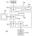
도 1은 본 발명의 일 실시예에 따른 SD 카드 타입으로 구현될 수 있는 데이터 저장 장치의 세부 구성을 도시한다.1 illustrates a detailed configuration of a data storage device that may be implemented as an SD card type according to an embodiment of the present invention.
도시한 데이터 저장 장치(100)는, SD 카드 프로토콜에 따라 데이터를 입력 또는 출력하는 메모리 카드 인터페이스로서 SD 카드 인터페이스(210); 상기 SD 카드 인터페이스로 인가되는 신호에 따라, 근거리 무선 통신으로서 NFC 통신을 수행하는 NFC 인터페이스(220); 상기 SD 카드 인터페이스(210)를 통해 입력되는 데이터를 저장하는 저장부(230); 및 상기 NFC 인터페이스(220)를 통한 소정의 인증 과정을 거쳐 접근할 수 있는 보안 모듈(240)로 이루어질 수 있다.The illustrated
상기 SD 카드 인터페이스(210)는, SD(Secure Digital) 카드를 위한 표준 규격에 따른 통신 제어 신호인 SD 카드 프로토콜에 대응하여, 데이터를 입/출력하는 구성으로서, 전용 IC와 같은 단일 하드웨어로 구현되거나, 하드웨어 및/또는 소프트웨어 모듈로 구현될 수 있다. 도면에서 상기 SD 카드 인터페이스(210)는, 상기 SD 카드 프로토콜에 따라 상기 저장부(230)에 데이터를 기록하거나 독출하는 동작을 수행할 수 있다.The
상기 데이터 저장 장치(100)는, 일렬로 정렬된 도전체 스트립 형태를 가지며, 외부의 메모리 카드 슬롯으로서 SD 카드 슬롯과 상기 SD 카드 인터페이스(210)를 연결 시키는, 메모리 카드 슬롯 접촉부로서 SD 카드 슬롯 접촉부(120)를 더 구비할 수 있다. 상기 SD 카드 슬롯 접촉부(120)는, 일반적인 SD 카드 규격을 따르거나, 미니 SD 카드 규격을 따르거나, 마이크로 SD 카드 규격을 따를 수 있다.
The
상기 저장부(230)는, 사용자가 원하는 정보들을 장시간 저장하기 위한 구성으로서, 비교적 대용량을 가지며 비휘발성 저장 메모리인 NAND, EEPROM 등으로 구현될 수 있다. 상기 저장부(230)는 대용량 이동식 저장 장치로서의 SD(Secure Digital) 카드의 본연의 기능을 제공하기 위한 것으로, 상기 SD 카드 인터페이스(210)에 의해 접근될 수 있는 저장 영역일 수 있다. 다른 구현에서는, 상기 저장부(230)는 상기 SD 카드 인터페이스(210) 뿐만 아니라, 상기 NFC 인터페이스(220)에 의해서도 접근될 수 있다.The
상기 보안 모듈(240)은, 보안을 위해 규정된 암호화 알고리즘을 수행하는 독립된 단일 칩(예: 스마트 칩)으로 구현될 수 있다. Mega SIM 등에 사용되는 고성능 스마트 칩으로 구현된 보안 모듈의 경우, 그 내부에 상당한 크기의 비휘발성 메모리를 구비할 수 있다.The
상기 보안 모듈(240)은, 본 실시예의 데이터 저장 장치(100)의 발급시, 상기 데이터 저장 장치를 식별하기 위한 식별 ID 및/또는 상기 암호화 알고리즘을 위한 암호키가 저장될 수 있다. 또는, 단일 칩으로 구현된 상기 보안 모듈(240)은, 상기 단일 칩의 식별 번호를 상기 식별 ID로 사용할 수 있다.The
상기 보안 모듈(240)은 NFC 프로토콜에 대응하여, 상기 암호화 알고리즘을 수행할 수 있으며, 이를 위해, 상기 NFC 인터페이스(220)로부터 보안 처리에 대한 명령을 입력받을 수 있다.
The
상기 NFC 인터페이스(220)는, NFC 통신을 위한 표준 규격에 따른 통신 제어 신호인 NFC 프로토콜에 대응하여, 데이터를 입/출력하는 구성으로서, 전용 IC와 같은 단일 하드웨어로 구현되거나, 하드웨어 및/또는 소프트웨어 모듈로 구현될 수 있다.The
현재, NFC 디바이스를 구현하는 데 있어서 가장 핵심적인 것이 소위 NFC 칩이라는 전용 IC이다. 회사에 따라 NFC 컨트롤러(Controller) 또는 NFC 라우터(Router)라고도 불리는 이 NFC 칩은 몇 군데 회사에서 개발해 시장에 출시하고 있다. 본 실시예의 NFC 인터페이스(220)는 상기 NFC 칩을 구비할 수 있다.At the present time, the key to implementing NFC devices is a dedicated IC called an NFC chip. The NFC chip, sometimes called the NFC controller or NFC router, is being developed and marketed by several companies.
상기 NFC 인터페이스(220)가 NFC 통신을 수행하기 위해서는, RF 신호를 송수신하기 위한 RF 안테나(140)와 연결되어야 한다. 상기 RF 안테나(140)는 루프 안테나 형태나 RF 마이크로 스트립 안테나 형태로 상기 데이터 저장 장치(100)에 구비되거나, 또는, 상기 데이터 저장 장치(100)가 설치되는 외부 전자 기기 내에 구비될 수 있다. 후자의 경우, 상기 데이터 저장 장치(100)는, 한쌍의 도전체 스트립 형태를 가지며, 상기 외부 전자 기기의 RF 안테나와 상기 NFC 인터페이스를 연결시키는 RF 안테나 접촉부를 더 구비할 수 있다.
In order for the
NFC에서는 통신하고자 하는 두 개의 디바이스가 동작공간(Operating Volume) 내에 진입하게 되면, 서로 통신하고자 하는 의사가 있는 것으로 간주하고, 통신절차를 개시하게 된다. 이러한 개념은 사용자의 편리성을 극대화시켜 준다.In NFC, when two devices to communicate with each other enter an operating volume, the intention to communicate with each other is assumed, and a communication procedure is started. This concept maximizes user convenience.
NFC 디바이스는 보통 세 가지 모드로 동작한다. 하나는 디바이스가 단말기의 역할을 하는 능동 모드(Reader/Writer mode), 다른 하나는 디바이스와 디바이스가 호상간 데이터를 교환하는 P2P 모드(Peer to Peer mode), 그리고 디바이스가 마치 비접촉식카드처럼 동작하는 수동 모드(Card Emulation mode)다.NFC devices usually operate in three modes. One is a reader / writer mode in which the device acts as a terminal, the other is a peer-to-peer mode in which the device exchanges data with each other, and a passive device in which the device behaves like a contactless card. Mode (Card Emulation mode).
능동 모드를 사용해 NFC 디바이스는 카드, 태그, 그리고 스마트 포스터 등을 읽을 수 있고, P2P 모드를 이용해 다른 NFC 디바이스와 전자명함, 디지털컨텐츠 등의 대량 데이터를 주고받을 수 있다. 마지막으로 수동 모드를 사용해 NFC 기능을 갖는 휴대전화기를 카드 단말기에 접촉해 지불행위를 하는 것이 가능하다.Active mode allows NFC devices to read cards, tags, and smart posters, and P2P mode to send and receive large amounts of data such as business cards and digital content with other NFC devices. Finally, it is possible to make a payment by touching a card terminal with a NFC-enabled mobile phone using the manual mode.
상기 NFC 인터페이스(220)는, 상기 메모리 카드 인터페이스를 통해 인가되는 신호에 따라, 수동 모드, 능동 모드 및 피투피 모드 중 하나를 선택하고, 상기 선택된 모드로 근거리 무선 통신을 수행할 수 있다.
The
본 실시예의 데이터 저장 장치(100)의 상기 NFC 인터페이스(220)는, 상기 SD 카드 인터페이스(210)로 인가되는 SD 프로토콜에 따른 명령에 응답하여, NFC 규격에 따른 근거리 무선 통신으로서 NFC 무선 통신을 수행할 수 있다. 이에 따라, 사용자는 상기 SD 카드 인터페이스(210)를 통해 상기 데이터 저장 장치에 접속된 외부 기기(예: 모바일폰, PC)를 이용하여, 상기 NFC 인터페이스(220)의 동작을 제어할 수 있다. 즉, 상기 사용자는 상기 외부 기기를 조작하여, 상기 데이터 저장 장치(100)의 NFC 기능을 제어할 수 있다. 이는 사용자에게 상기 외부 기기의 NFC 기능을 수행하는 것과 같은 느낌을 부여한다.The
이를 위해, 도시한 상기 데이터 저장 장치(100)는, 상기 SD 카드 인터페이스(210)와 NFC 인터페이스(220) 사이에서 제어 신호를 변환하여 중계하는 프로토콜 변환부(260)를 더 구비할 수 있다. 또는, 상기 프로토콜 변환부(260)의 기능을 상기 NFC 인터페이스(220) 또는 SD 카드 인터페이스(210)가 가지도록 구현할 수 있다.
To this end, the illustrated
한편, 도 1에 도시한 데이터 저장 장치(100)는, 접촉식 IC를 위한 규격(예: ISO 7816)에 따른 접촉식 프로토콜에 따라 데이터 통신을 수행하는 접촉식 인터페이스(270)를 더 포함할 수 있다. 상기 접촉식 인터페이스(270)는, 상기 접촉식 인터페이스(270)를 통해 상기 보안 모듈(240)에 접근할 수 있거나, 및/또는 상기 접촉식 인터페이스(270)를 통해 상기 저장부(230)에 접근할 수 있도록 구성될 수 있다. 또는, 상기 데이터 저장 장치(100)가, 상기 접촉식 인터페이스(270)를 위한 보안 및/또는 저장 기능을 수행하는 다른 하드웨어(예: IC)를 더 구비할 수 있다. 또한, 상기 데이터 저장 장치(100)는, 외부 기기의 접촉식 IC 슬롯과 상기 접촉식 인터페이스(270)를 연결시키는 접촉식 패드(160)를 더 구비할 수 있다. 예컨대, 상기 접촉식 패드(160)는, 6개의 도전체 스트립 형태를 가질 수 있다.Meanwhile, the
상기 접촉식 인터페이스(270)는 접촉식 프로토콜을 이용하여 외부의 접촉식 IC 카드 단말기와 인증 과정을 수행하거나 필요한 데이터를 입/출력할 수 있다. 예컨대, 상기 보안 모듈(240) 등에 전자화폐를 저장하고, 상기 접촉식 인터페이스(270)를 이용하여, 외부의 접촉식 IC 카드 결제 단말기에 접촉하여, 상기 전자화폐로 대금 결제를 수행할 수 있다.The
그런데, 현재 접촉식 IC 카드를 위한 단말기의 보급 상황은 좋지 못하여, 본 실시예의 데이터 저장 장치(100)는, 접촉식 IC 카드로 사용될 가능성이 크지 않다. 그러나, 보다 보안성이 높은 접촉식 IC 카드의 특성상, 스마트 카드를 발급하는 발급기는, 접촉식 IC 카드에 대한 접촉식 프로토콜을 이용해 발급을 수행하는 것이 많다. 따라서, 상기 접촉식 인터페이스(270)는 상기 데이터 저장 장치(100) 자체의 발급 과정에 사용될 때 보다 유용하다. 발급시 상기 접촉식 인터페이스(270)는, 상기 데이터 저장 장치(100) 자체의 식별 정보(예: 식별 ID) 및/또는 암호키를 입력받아, 상기 보안 모듈(240) 및/또는 저장부(230)에 기록할 수 있다. 상기 접촉식 인터페이스(270)를 이용한 구체적인 발급 과정은 후술하겠다.
However, the current situation of dissemination of a terminal for a contact IC card is not good, so the
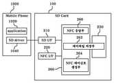
도 2는 상기 프로토콜 변환부(260)의 세부 구성 및 이에 대응하는 외부 기기(1000)의 소프트웨어 계층 구조의 일 예를 도시한다. 이하에서는, 도 2를 참조하여 상기 프로토콜 변환부(260)의 프로토콜 변환 동작의 일 예를 설명하겠다.2 illustrates an example of a detailed configuration of the
상기 SD 프로토콜은 비교적 대용량의 메모리에, 데이터를 기록하기 위한 것이며, 상기 SD 카드 인터페이스(210)는 상기 SD 프로토콜에 따라 입력되는 데이터를 저장하기 위한 저장 공간(어드레스 영역)을 가진다. 여기서, 상기 저장 공간은 내부 메모리 및/또는 도 1의 저장부(230)에 대한 어드레스 영역일 수 있다.The SD protocol is for recording data in a relatively large memory, and the
본 실시예에서는, 상기 SD 카드 인터페이스(210)에 할당된 저장 공간 중 특정한 영역을, 상기 NFC 인터페이스(220)에 대한 NFC 명령을 기록하는데 사용한다. 이를 위해, 상기 프로토콜 변환부(260)는, 상기 특정한 영역으로서 상기 SD 카드 인터페이스(210)를 통해 입력되는 정보를 저장하는 제어파일 저장부(262); 및 상기 제어파일 저장부(262)에 저장된 정보를 해석하여 상기 NFC 인터페이스(220)에 대한 제어 신호를 생성하는 NFC 제어 신호 생성부(264)를 구비할 수 있다.In this embodiment, a specific area of the storage space allocated to the
도시한 구현에서 상기 제어파일 저장부(262)는, 저장부(230)의 일부 영역이지만, 설명 및 이해의 편의를 위해 그 기능에 따른 분류를 적용하여, 상기 프로토콜 변환부(260)의 세부 구성요소로서 구분하여 표현하였다.In the illustrated embodiment, the control
한편, 다른 구현에서는, 상기 제어파일 저장부(262)는, 상기 프로토콜 변환부(260)를 구성하는 하드웨어 내부의 메모리(예: 레지스터)이거나, 상기 SD 카드 인터페이스(210) 및/또는 NFC 인터페이스(220)의 내부 메모리(예: 레지스터)일 수 있다.In another implementation, the control
한편, 또 다른 구현에서는, 상기 NFC 제어 신호 생성부(264)의 기능을 상기 NFC 인터페이스(220)가 수행하고, 상기 NFC 제어 신호 생성부(264)는 생략될 수 있다. 한편, 상기 프로토콜 변환부(260)는, NFC 작업 수행에 대한 응답을 상기 제어파일 저장부(262)에 저장하기 위한 NFC 응답부(266)를 더 구비할 수 있다.
Meanwhile, in another implementation, the
본 실시예의 데이터 저장 장치(100)에 접속된 외부 기기(1000)(예: 모바일폰, PC)는, 사용자가 상기 데이터 저장 장치의 NFC 기능을 명령하면, 이에 해당하는 NFC 명령을 포함하는 파일(NFC 명령 파일)을 생성하고, 상기 SD 프로토콜을 이용하여 상기 생성된 NFC 명령 파일을 상기 제어파일 저장부(262)에 기록한다. 이를 위해 상기 외부 기기(1000)에는, 상기 기능을 수행하는 소프트웨어(예: 드라이버 등)가 설치되어 구비될 수 있다.The external device 1000 (for example, mobile phone or PC) connected to the
상기 NFC 제어 신호 생성부(264)는, 주기적으로 상기 제어파일 저장부(262)를 검색하여, 상기 NFC 제어 신호를 포함하는 파일의 존재 여부를 확인할 수 있다. 상기 NFC 제어 신호 생성부(264)는, 상기 제어파일 저장부(262)에 기록된 파일을 열어서, 상기 외부 기기(1000)로부터의 명령 사항을 확인하고, 이를 NFC 프로토콜에 따른 제어 신호로 변환하고, 상기 변환된 제어 신호를 상기 NFC 인터페이스(220)로 출력할 수 있다.The NFC
상기 내용을, 상기 외부 기기(1000)로서 모바일 폰의 마이크로 SD 카드 슬롯에 본 발명의 사상에 따른 데이터 저장 장치가 장착된 경우의 동작으로 구체화하여 설명하면 다음과 같다. 상기 모바일 폰에는 본 발명의 사상에 따른 데이터 저장 장치를 제어하기 위한 어플리케이션(1020)이 설치되어 있고, 상기 마이크로 SD 슬롯에 연결된 일반적인 SD 카드에 접근하기 위한 소프트웨어로서 SD 드라이버(1040)가 설치되어 있다.The above description will be specifically described as an operation when the data storage device according to the spirit of the present invention is mounted in the micro SD card slot of the mobile phone as the
상기 모바일 폰의 사용자가 다른 모바일 폰으로 저장된 이미지를 NFC의 PtoP 기능을 이용하여 전송하고자 한다. 즉, 상기 어플리케이션(1020)은 PtoP 이미지 전송 기능을 수행할 수 있다. 사용자가 상기 모바일 폰의 NFC 이미지 전송을 위해 상기 어플리케이션(1020)을 실행시키면, 상기 어플리케이션(1020)은 PtoP 모드로 동작하라는 명령을 포함하는 파일(NFC 명령 파일)을 생성하고, SD 프로토콜을 이용하여 상기 생성된 NFC 명령 파일을 상기 데이터 저장 장치(100) 내 제어파일 저장부(262)에 저장한다.A user of the mobile phone wants to transmit an image stored in another mobile phone using the PtoP function of NFC. That is, the
다음, 상기 데이터 저장 장치(100) 내 NFC 제어 신호 생성부(264)는, 상기 제어파일 저장부(262)에 상기 파일이 기록되어 있는 것을 확인하면, 상기 기록된 NFC 명령 파일을 독출하여 열어본다. 상기 NFC 제어 신호 생성부(264)는 상기 NFC 명령 파일에 기재된 PtoP 모드로 동작하라는 명령에 대한 NFC 제어 신호를 생성하여, 상기 데이터 저장 장치(100) 내 NFC 인터페이스(220)로 출력한다.Next, when the NFC control
상기 제어 신호를 입력받은 상기 NFC 인터페이스(220)는, 도 1에 도시한 알에프 안테나(140)를 이용하여 PtoP 모드로 외부의 다른 모바일 폰과 NFC 무선 통신 채널을 형성하고, 상기 명령에 대한 NFC 작업의 보고 내용을 작성하여, 상기 NFC 응답부(266)로 전달한다. 상기 NFC 응답부(266)는, 상기 보고 내용을 포함하는 파일(NFC 응답 파일)을 생성하고, 상기 생성된 파일을 상기 제어파일 저장(262)부에 기록한다.The
상기 어플리케이션(1020)은, 상기 데이터 저장 장치(100) 내 상기 제어파일 저장부(262)에 NFC 명령 파일을 저장한 후, 상기 제어파일 저장부(262)에 NFC 응답 파일이 저장되는가를 주기적으로 검사할 수 있다. 상기 어플리케이션(1020)은, 상기 제어파일 저장부(262)에 NFC 응답 파일이 저장되어 있으면, 이를 독출하여 내부에 기재된 보고 내용을 획득할 수 있다.The
상술한 과정에 따라, 상기 다른 모바일 폰과 NFC 무선 통신 채널을 형성한 것에 대한 보고 내용을 획득한 상기 어플리케이션(1020)은, 사용자의 상기 모바일 폰 조작에 따라, 상기 다른 모바일 폰으로 전송할 이미지를 선택하고, 선택한 전송할 이미지에 대한 정보 및 전송 명령을, 상술한 것과 유사한 과정으로 NFC 명령 파일의 형태로 지시하고(즉, NFC 명령 파일을 상기 제어파일 저장부(262)에 저장), 이에 대한 응답(NFC 응답 파일)을 확인할 수 있다.According to the above-described process, the
여기서, 상기 전송할 이미지의 저장 위치에 따라, 상기 전송할 이미지에 대한 정보를 보내는 형태는 하기 3가지 중 하나가 될 수 있다.Here, according to the storage location of the image to be transmitted, the form of sending information on the image to be transmitted may be one of the following three types.
첫째로, 상기 전송할 이미지가 상기 NFC 인터페이스(220)가 직접 접근할 수 있는 영역에 저장된 경우, 상기 전송할 이미지에 대한 정보는, 상기 이미지가 저장된 영역 정보(예: 이미지 저장 위치의 어드레스)가 될 수 있다. 여기서, NFC 인터페이스(220)가 직접 접근할 수 있는 영역은, 상기 NFC 인터페이스(220)가 접근할 수 있는 도 1의 보안 모듈(240)의 내부 저장 영역이거나, NFC 인터페이스(220)가 도 1의 저장부(230)를 직접 접근할 수 있는 구조의 구현의 경우, 상기 저장부(230)의 일부 저장 영역일 수 있다.First, when the image to be transmitted is stored in an area directly accessible by the
둘째로, 상기 전송할 이미지가 상기 NFC 인터페이스(220)가 직접 접근할 수 없는 영역에 저장된 경우, 상기 전송할 이미지에 대한 정보는, 전송할 이미지 데이터의 전부 또는 일부가 될 수 있다. 이 경우, 상기 제어파일 저장부(262)를 통해 상기 전송할 이미지 자체가 분할되어(또는 한번에) 전송될 수 있다. 즉, 상기 어플리케이션(1020)은, 상기 전송할 이미지 데이터를 획득한 후, 상기 전송할 이미지 데이터의 전부 또는 분할된 일부를 상기 NFC 명령 파일 내에 삽입시켜, 상기 제어파일 저장부(262)에 저장할 수 있다.
Second, when the image to be transmitted is stored in an area where the
상술한 설명들에서, 상기 제어파일 저장부(262)에 상기 NFC 명령 파일이 저장되는 영역과, 상기 NFC 응답 파일이 기록되는 영역은, 구현에 따라 동일하거나, 다를 수 있다. 또한, 상기 제어파일 저장부(262)의 저장 영역 확보를 위해, 상기 제어파일 저장부(262)에 기록되었던 파일(NFC 명령 파일 및/또는 NFC 응답 파일)은, 상기 NFC 제어 신호 생성부(264) 또는 상기 어플리케이션(1020)이 확인한 후에는 삭제될 수 있다.
In the above descriptions, the area in which the NFC command file is stored in the control
도 3은 본 발명의 사상에 따른 데이터 저장 장치의 일 실시예의 외형을 도시한다.3 illustrates the appearance of an embodiment of a data storage device according to the spirit of the present invention.
도시한 데이터 저장 장치(100-1)는, 직사각형 판에 대한 유사 형상을 가지는 케이스(101); 상기 케이스(101)의 일면의 일변 부근에 일렬로 정렬된 도전체 스트립(ss1 ~ ss8) 형태를 가지며, 외부의 메모리 카드 슬롯에 접촉될 수 있는 메모리 카드 슬롯 접촉부로서 마이크로 SD 카드 슬롯 접촉부(120); 상기 케이스(101)의 일면에 형성된 6개의 도전체 스트립(cs1 ~ cs 6) 형태를 가지며, 외부의 접촉식 IC 슬롯에 접촉될 수 있는 접촉식 패드; 상기 케이스(101)의 일면 또는 타면에 형성된 한쌍의 도전체 스트립(as1, as2) 형태를 가지며, 외부의 RF 안테나와 연결될 수 있는 RF 안테나 접촉부; 및 상기 케이스(101) 내부에 장착되며, 상기 마이크로 SD 카드 슬롯 접촉부(120), 접촉식 패드 및 RF 안테나 접촉부로 입력되는 신호들을 처리하여 획득된 정보를 저장하는 내부 회로 블록(200)을 포함할 수 있다.The illustrated data storage device 100-1 includes a
여기서, 상기 내부 회로 블록(200)은, 도 1에 도시한 내부 회로 블록(200)의 구성 요소들을 구비할 수 있다.Here, the
상기 케이스(101)는 일반적인 마이크로 SD 카드의 형상을 가질 수 있다. 현재 널리 통용되는 마이크로 SD 카드는 직사각형 형상을 가지된 장변 중 하나에 지그재그형 굴곡이 형성된 형태를 가진다. 따라서, 도시한 케이스(101)도 마찬가지의 형태를 가지고 있다.The
상기 마이크로 SD 카드 슬롯 접촉부(120)도 일반적인 규격의 마이크로 SD 카드와 동일한 형상을 가지는 것이, 마이크로 SD 카드로서의 호환성을 확보하는데 유리하다.The micro SD card
도시한, 마이크로 SD 카드 슬롯 접촉부(120)는, 일렬로 정렬된 도전체 스트립(ss1 ~ ss8) 형태를 가지며, 외부 기기의 마이크로 SD 카드 슬롯과 상기 내부 회로 블록(200) 내 메모리 카드 인터페이스를 연결시키는 물리적 구조이다.The illustrated micro SD card
도시한 RF 안테나 접촉부는, 한쌍의 도전체 스트립(as1, as2) 형태를 가지며, 외부의 RF 안테나와 상기 내부 회로 블록(200) 내 NFC 인터페이스를 연결시키는 물리적 구조이다.The illustrated RF antenna contact has a form of a pair of conductor strips as1 and as2, and is a physical structure that connects an external RF antenna to an NFC interface in the
도시한 접촉식 패드는, 6개의 도전체 스트립(cs1 ~ cs6) 형태를 가지며, 외부의 접촉식 IC 슬롯과 상기 내부 회로 블록(200) 내 접촉식 IC 인터페이스를 연결시키는 물리적 구조이다.
The illustrated contact pad has the form of six conductor strips cs1 to cs6, and is a physical structure that connects an external contact IC slot with a contact IC interface in the
ISO 7816 규격의 접촉식 패드는, 2개의 예비용 단자를 포함하여, 모두 8개의 단자들로 이루어진다. 그런데, ISO 7816 규격의 접촉식 패드는 상당히 오래전에 제안된 것임에도 불구하고, 실제로 사용되는 경우를 발견하기가 쉽지 않다. 비접촉식 스마트 카드에 비해, 접촉식에 대한 불편함이 일반 소비자들로부터 외면받은 것이다. 상기 ISO 7816 규격의 접촉식 패드가 비교적 널리 사용되는 유일한 분야가, 모바일 폰의 USIM이다.The contact pad of
먼저, 상기 USIM에 대하여 간략히 살펴보겠다. 가입자식별모듈(subscriber identify module; SIM) 카드는 상기와 같이 정의한 스마트카드의 일 이용 형태인 것으로, 이동통신단말기에 장착되어 단말기 사용자의 인증을 위한 일종의 스마트 카드로서, 과금 및 보안 기능 등 다양한 서비스를 제공할 수 있다. 여기서, 이러한 가입자식별모듈(SIM) 카드는 GSM(Global System for Mobile communication)방식을 채택하고 있는 유럽에서 시작되었으며, 한편, CDMA(code division multiple access) 진영에서는 기능적으로는 동일한 스마트 카드를 제안하여, 상기한 SIM과 구별하기 위해서 UIM(user identify module)이라는 용어를 사용하고 있다. 또한, USIM(user subscriber identifyFirst, the USIM will be briefly described. A subscriber identify module (SIM) card is a form of use of a smart card defined as above, and is a smart card for authentication of a terminal user mounted on a mobile communication terminal, and provides various services such as billing and security functions. Can provide. Here, the subscriber identity module (SIM) card is started in Europe adopting the Global System for Mobile communication (GSM) scheme, while the code division multiple access (CDMA) camp proposes a functionally identical smart card. The term UIM (user identify module) is used to distinguish it from the SIM. In addition, USIM (user subscriber identify)
module)은 SIM과 UIM을 모두 수용하는 보다 확장된 개념의 용어로써, ITU의 IMT-2000 무선 접속규격이 동기식과 비동기식이 동시에 복수로 승인됨에 따라 이제는 서로 다른 무선접속표준을 이용하여 로밍을 구현하는 실제적인 방법이 되고 있는바, 사용자 인증을 위한 USIM에 대한 표준이 적극적으로 추진중에 있는 실정이다. 본 명세서에서는 SIM이 UIM을 통칭할 수 있는 용어인 USIM을 사용한다.module) is a more extended term that accepts both SIM and UIM. As ITU-2000's IMT-2000 radio access standard is approved in synchronous and asynchronous manner, it is now possible to implement roaming using different radio access standards. As a practical method, the USIM standard for user authentication is actively being promoted. In this specification, SIM uses USIM, a term that can collectively refer to UIM.
본 실시예의 데이터 저장 장치(100-1)는, 상기 ISO 7816 규격의 접촉식 패드를 위한 접촉식 카드 슬롯에 연결될 수 있도록, 상기 ISO 7816 규격의 접촉식 패드의 사용 중인 6개의 접촉부와 대응하는 위치에 6개의 도전체 스트립(cs1 ~ cs6) 형태의 접촉식 패드를 구비할 수 있다. 상기 ISO 7816 규격의 접촉식 패드에서 사용하지 않고 예비용으로 사용하는 2개의 접촉부에 대해서도 2개의 도전체 스트립을 형성할 수도 있지만, 제작 비용면에서 도면과 같이 생략하는 것이 유리하다.The data storage device 100-1 of this embodiment corresponds to the position of six contacts in use of the contact pad of the
본 실시예의 데이터 저장 장치(100-1)에 구비된 상기 접촉식 패드는, 접촉식 스마트 카드로 사용되기 위한 용도를 가질 수 있으며, 또한, 현재 널리 사용되는 USIM 카드로 사용되기 위한 용도를 가질 수 있다. 그러나, 마이크로 SD 카드와 USIM 카드와는 외형상 크기부터 차이가 있으므로, 그대로 사용하지 않고 일종의 변환 케이스(adapter case)를 이용할 수 있다.
The contact pad provided in the data storage device 100-1 of this embodiment may have a purpose for use as a contact smart card, and may also have a purpose for use as a USIM card which is widely used at present. have. However, since the micro SD card and the USIM card differ in appearance, they can use a kind of adapter case without being used as it is.
도 4는 도 3의 데이터 저장 장치(100-1)를 USIM 카드로 사용될 수 있도록 변환 케이스(900)에 결합한 형상을 도시한다. 도시한 바와 같이 본 실시예의 데이터 저장 장치(100-1)가 상기 변환 케이스(900)에 결합되면, USIM의 형태를 갖추게 된다. 여기서, 상기 변환 케이스(900)는 USIM의 외형을 가지며, 내부에 상기 데이터 저장 장치(100-1)의 케이스(101)가 끼어질 수 있는 홈을 구비한다.FIG. 4 illustrates a shape in which the data storage device 100-1 of FIG. 3 is coupled to the
상기 데이터 저장 장치의 접촉식 패드를 구성하는 6개의 도전체 스트립들(cs1 ~ cs6)과, 일반적인 USIM(2000)에 부착된 ISO 7816 규격의 접촉식 패드(2100)와 비교하면, 상기 ISO 7816 규격의 접촉식 패드(2100)의 예비용으로 보류된 2개의 접촉부들(cp7,cp8 )을 제외한 6개의 접촉부들(cp1 ~ cp6)의 위치가, 상기 6개의 도전체 스트립들(cs1 ~ cs6)의 위치에 대응됨을 알 수 있다. 그 결과, 상기 데이터 저장 장치(100-1)가 상기 변환 케이스(900)에 결합된 상태로 외부 기기(예: 모바일 폰)의 USIM 슬롯에 끼워지면, 상기 6개의 도전체 스트립들(cs1 ~ cs6)로 이루어진 접촉식 패드를 이용하여 ISO 7816 규격의 접촉식 데이터 통신을 수행할 수 있게 된다.
Compared to the six conductor strips cs1 to cs6 constituting the contact pad of the data storage device and the contact pad 2100 of the
도 4에 도시한 형태의 상기 변환 케이스(900)에 결합된 상기 데이터 저장 장치(100-1)는, 모바일 폰의 USIM 슬롯에 끼워지기 보다는, 상기 데이터 저장 장치(100-1) 자신의 발급 과정에서 사용될 수 있다. 여기서, '발급(issuing)'이란, 사전전 의미로서는 "증명서 따위를 발행하여 줌"이지만, 스마트 카드를 '발급'하는 것은, 카드를 사용자에게 발행하고 카드의 사용 권한을 부여하는 것으로서, 스마트 카드의 특성상 스마트 카드의 정당한 사용 권한을 부여하기 위한 보안 절차를 수행하는 것을 포함한다. 보다 구체적으로 전자/전산 처리 과정에서 '발급'은, 상기 정당한 사용 권한을 부여하기 위한 보안 절차를 수행하는 것을 의미하며, 예컨대, 상기 '보안 절차'에는, 각 스마트 카드(본 실시예의 데이터 저장 장치도 일종의 스마트 카드로 볼 수 있다)에 식별 정보(예: 식별 ID)를 부여하는 것 및/또는 각 각 데이터 저장 장치의 인증에 필요한 보안키를 저장하는 것을 포함할 수 있다.The data storage device 100-1 coupled to the
널리 보급된 종래 기술에 따른 USIM 카드의 발급기는, SD 카드 방식이나, NFC 방식보다는, ISO 7816 규격의 접촉식 카드 방식을 이용하여, 발급 업무를 수행하고 있다. 도시한 같이 변환 케이스(900)에 결합된 상기 데이터 저장 장치(100-1)의 접촉식 패드(cs1 ~ cs6)를 이용하면, 상기 종래 기술에 따른 USIM 카드의 발급기를 이용하여, 본 발명의 사상에 따른 데이터 저장 장치(100-1)를 발급할 수 있다.The issuer of the USIM card according to the prior art, which has been widely spread, performs an issuing task by using a contact card method of the
즉, 도 3 및 도 4에 도시한 데이터 저장 장치(100-1)는, NFC 인터페이스가 없는 전자 기기(예: 모바일 폰)의 마이크로 SD 카드 슬롯에 끼워지면, 상기 전자 기기에 NFC 기능을 지원하는 효과가 있으면서도, 종래 기술에 따른 USIM 카드의 발급기를 이용하여 저렴한 비용으로 발급될 수 있는 이점이 있다.That is, when the data storage device 100-1 shown in FIGS. 3 and 4 is inserted into a micro SD card slot of an electronic device (eg, a mobile phone) without an NFC interface, the data storage device 100-1 may support the NFC function. While effective, there is an advantage that can be issued at a low cost by using the issuer of the USIM card according to the prior art.
예컨대, 도 3 및 도 4에 도시한 데이터 저장 장치(100-1)는, 모바일 폰의 마이크로 SD 카드 슬롯에 끼워져서, 상기 모바일 폰에 NFC 기능을 부여하도록 사용될 수 있다. 여기서, 상기 모바일 폰은, NFC 기능을 위한 하드웨어를 구현하지 않아도 되나, 도 2에 도시한 NFC 기능을 위한 어플리케이션(1020)이 인스톨되어 있어야 하고, 상기 데이터 저장 장치(100-1)가 마이크로 SD 카드 슬롯에 끼워졌을 때, 한쌍의 도전체 스트립(as1, as2)으로 이루어진 상기 데이터 저장 장치(100-1)의 안테나 접촉부와 접촉되는 물리적 구조를 가지는 RF 루프 안테나가 구비되여야 한다.For example, the data storage device 100-1 shown in FIGS. 3 and 4 may be used to provide an NFC function to the mobile phone by being inserted into a micro SD card slot of the mobile phone. In this case, the mobile phone does not need to implement hardware for the NFC function, but the
상기 어플리케이션(1020)은 상기 모바일 폰의 응용 프로그램으로서 인스톨이 용이하고, 상기 루프 안테나는 배터리 팩의 형태 등 로 구현 비용이 저렴하므로, 본 실시예의 데이터 저장 장치(100-1)를 이용하면, 모바일 폰에 NFC 기능을 부여하는 비용을 절감할 수 있다.
Since the
그러나, 도 3에 도시한 실시예에 따른 데이터 저장 장치는 RF 통신을 위한 루프 안테나가 구비된 모바일 폰을 요구하는데, 이는 기존의 NFC 기능이 없는 모바일 폰에 NFC 기능을 부여하는데 제한으로 작용한다.However, the data storage device according to the embodiment shown in FIG. 3 requires a mobile phone equipped with a loop antenna for RF communication, which acts as a limitation in granting an NFC function to a mobile phone without a conventional NFC function.
도 5a 및 도 5b에 도시한 다른 실시예에 따른 데이터 저장 장치(100-2)는, 마이크로 SD 슬롯이 존재하고, 추가 어플리케이션을 인스톨할 수 있는 모든 모바일 폰에, NFC 기능을 부여할 수 있다.The data storage device 100-2 according to another embodiment illustrated in FIGS. 5A and 5B may provide an NFC function to all mobile phones in which a micro SD slot exists and in which additional applications can be installed.
도시한 데이터 저장 장치(100-2)는, 직사각형 판에 대한 유사 형상을 가지는 케이스(102); 상기 케이스(102)의 일면의 일변 부근에 일렬로 정렬된 도전체 스트립(ss1 ~ ss8) 형태를 가지며, 외부의 메모리 카드 슬롯에 접촉될 수 있는 메모리 카드 슬롯 접촉부로서 마이크로 SD 카드 슬롯 접촉부(120); 상기 케이스(102)의 일면에 형성된 6개의 도전체 스트립(cs1 ~ cs 6) 형태를 가지며, 외부의 접촉식 IC 슬롯에 접촉될 수 있는 접촉식 패드; 상기 케이스(102)의 상기 마이크로 SD 카드 슬롯 접촉부(120)의 반대편 변에 위치하며, NFC 무선 통신을 위한 RF 신호를 송수신하기 위한 일종의 마이크로 스트립 안테나로서 RF 스트립 안테나(SA); 및 상기 케이스(102) 내부에 장착되며, 상기 마이크로 SD 카드 슬롯 접촉부(120), 접촉식 패드 및 RF 스트립 안테나(SA)로 입력되는 신호들을 처리하여 획득된 정보를 저장하는 내부 회로 블록(200)을 포함할 수 있다.The illustrated data storage device 100-2 includes a
도 5의 데이터 저장 장치(100-2)도 도 4에 도시한 바와 같이 변환 케이스(900)에 결합된 형태로, 외부 기기(예: 모바일 폰, USIM 카드 발급기)의 접촉식 IC 카드 슬롯(예: USIM 카드 슬롯)에 끼워져서 사용될 수 있다.The data storage device 100-2 of FIG. 5 is also coupled to the
상기 RF 스트립 안테나(SA)를 제외한 구성요소들은, 상기 도 3의 경우와 유사하므로 중복되는 상세 설명을 생략하겠다.Components other than the RF strip antenna SA are similar to those of FIG. 3, and thus detailed descriptions thereof will be omitted.
일반적인 마이크로 SD 카드는, 사용자가 마이크로 SD 카드 슬롯 접촉부의 반대편 변을 밀어 주는 방식으로, 외부 기기의 마이크로 SD 카드 슬롯에 끼워진다. 그 결과, 상기 마이크로 SD 카드 슬롯 접촉부의 반대편 변은, 외부 기기의 마이크로 SD 카드 슬롯으로부터 노출되는 경우가 많다. 본 실시예에서는 상기 마이크로 SD 카드 슬롯 접촉부의 반대편 변에 상기 RF 스트립 안테나(SA)를 형성시킴으로써, 상기 RF 스트립 안테나(SA)의 송수신 감도 향상을 도모하였다.A general micro SD card is inserted into a micro SD card slot of an external device by a user pushing the opposite side of the micro SD card slot contact. As a result, the opposite side of the micro SD card slot contact portion is often exposed from the micro SD card slot of the external device. In this embodiment, the RF strip antenna SA is formed on the opposite side of the micro SD card slot contact, thereby improving transmission and reception sensitivity of the RF strip antenna SA.
한편, 상기 RF 스트립 안테나(SA)는 NFC 통신을 위한 주파수 대역(예: 13.56MHz)에서 송수신 감도가 높은 형상으로 제작될 수 있다.
The RF strip antenna SA may be manufactured in a shape having high transmission and reception sensitivity in a frequency band (for example, 13.56 MHz) for NFC communication.
상기한 실시예는 그 설명을 위한 것이며, 그 제한을 위한 것이 아님을 주의하여야 한다. 또한, 본 발명의 기술분야의 통상의 전문가라면 본 발명의 기술사상의 범위에서 다양한 실시예가 가능함을 이해할 수 있을 것이다.
It should be noted that the above embodiment is for the purpose of illustration and not for the purpose of limitation. In addition, those skilled in the art will understand that various embodiments are possible within the scope of the technical idea of the present invention.
100 : 데이터 저장 장치 120 : SD 카드 슬롯 접촉부
140 : RF 안테나 160 : 접촉식 패드
200 : 내부 회로 블록 210 : SD 카드 인터페이스
220 : NFC 인터페이스 230 : 저장부
240 : 보안 모듈 260 : 프로토콜 변환부100: data storage device 120: SD card slot contact
140: RF antenna 160: contact pad
200: internal circuit block 210: SD card interface
220: NFC interface 230: storage unit
240: security module 260: protocol conversion unit
Claims (15)
Translated fromKorean상기 메모리 카드 인터페이스로 인가되는 신호에 따라, 소정의 RF 통신 프로토콜에 따른 근거리 무선 통신을 수행하는 NFC 인터페이스; 및
상기 메모리 카드 인터페이스를 통해 입력되는 데이터를 저장하는 저장부
를 포함하는 데이터 저장 장치.
A memory card interface for performing data input and output according to a predetermined memory card protocol;
An NFC interface for performing short range wireless communication according to a predetermined RF communication protocol according to a signal applied to the memory card interface; And
A storage unit for storing data input through the memory card interface
Data storage device comprising a.
상기 NFC 인터페이스는,
상기 메모리 카드 인터페이스로 인가되는 신호에 따라, 수동 모드, 능동 모드 및 피투피(PtoP) 모드 중 하나를 선택하고, 상기 선택된 모드로 NFC 규약에 따른 근거리 무선 통신을 수행하는 데이터 저장 장치.
The method of claim 1,
The NFC interface,
And selecting one of a passive mode, an active mode, and a PtoP mode according to a signal applied to the memory card interface, and performing short-range wireless communication according to NFC protocol in the selected mode.
상기 NFC 인터페이스를 통한 소정의 인증 과정을 거쳐 접근될 수 있는 보안 모듈
을 더 포함하는 데이터 저장 장치.
The method of claim 1,
Security module that can be accessed through a predetermined authentication process through the NFC interface
Data storage device further comprising.
상기 메모리 카드 인터페이스로 인가되는 신호를 NFC 제어 신호로 변환하여 상기 NFC 인터페이스로 전달하는 프로토콜 변환부
를 더 포함하는 데이터 저장 장치.
The method of claim 1,
Protocol conversion unit for converting the signal applied to the memory card interface to the NFC control signal to transfer to the NFC interface
Data storage device further comprising.
상기 프로토콜 변환부는,
상기 메모리 카드 인터페이스를 통해 입력되는 파일을 저장하는 제어파일 저장부; 및
상기 제어파일 저장부에 저장된 파일을 해석하여 상기 NFC 제어 신호를 생성하는 NFC 제어 신호 생성부
를 포함하는 데이터 저장 장치.
The method of claim 4, wherein
The protocol conversion unit,
A control file storage unit for storing a file input through the memory card interface; And
NFC control signal generation unit for generating the NFC control signal by analyzing the file stored in the control file storage unit
Data storage device comprising a.
상기 제어파일 저장부는,
상기 저장부의 일부 영역인 데이터 저장 장치.
The method of claim 5, wherein
The control file storage unit,
The data storage device is a partial area of the storage unit.
상기 프로토콜 변환부는,
NFC 작업 수행에 대한 응답을 상기 제어파일 저장부에 저장하기 위한 NFC 응답부
를 더 포함하는 데이터 저장 장치.
The method of claim 5, wherein
The protocol conversion unit,
NFC response unit for storing a response to the NFC operation to the control file storage unit
Data storage device further comprising.
일렬로 정렬된 도전체 스트립 형태를 가지며, 외부의 메모리 카드 슬롯과 상기 메모리 카드 인터페이스를 연결시키는 메모리 카드 슬롯 접촉부
를 더 포함하는 데이터 저장 장치.
The method of claim 1,
Memory card slot contacts that have the form of conductor strips arranged in a line and connect an external memory card slot with the memory card interface
Data storage device further comprising.
한쌍의 도전체 스트립 형태를 가지며, 외부의 RF 안테나와 상기 NFC 인터페이스를 연결시키는 RF 안테나 접촉부
를 더 포함하는 데이터 저장 장치.
The method of claim 1,
RF antenna contacts having a pair of conductor strips and connecting an external RF antenna to the NFC interface
Data storage device further comprising.
도전체 스트립 형태를 가지며, 외부의 RF 신호를 송수신하며, 상기 NFC 인터페이스에 연결된 RF 스트립 안테나
를 더 포함하는 데이터 저장 장치.
The method of claim 1,
An RF strip antenna having a conductor strip shape, transmitting and receiving an external RF signal, and connected to the NFC interface.
Data storage device further comprising.
소정의 접촉식 IC 프로토콜에 따른 데이터 통신을 수행하는 접촉식 인터페이스; 및
6개의 도전체 스트립 형태를 가지며, 외부의 접촉식 IC 슬롯과 상기 접촉식 인터페이스를 연결시키는 접촉식 패드
를 더 포함하는 데이터 저장 장치.
The method of claim 3, wherein
A contact interface for performing data communication in accordance with a predetermined contact IC protocol; And
Contact pads in the form of six conductor strips that connect an external contact IC slot to the contact interface
Data storage device further comprising.
상기 접촉식 인터페이스는,
상기 데이터 저장 장치의 식별 정보 또는 암호키를 입력받아, 상기 보안 모듈 또는 상기 저장부에 기록하는 것을 특징으로 하는 데이터 저장 장치.
The method of claim 11,
The contact interface,
And receiving identification information or an encryption key of the data storage device and writing the identification information or the encryption key to the security module or the storage unit.
상기 케이스의 일면의 일변 부근에 일렬로 정렬된 도전체 스트립 형태를 가지며, 외부의 메모리 카드 슬롯에 접촉될 수 있는 메모리 카드 슬롯 접촉부;
상기 케이스의 일면에 형성된 6개의 도전체 스트립 형태를 가지며, 외부의 접촉식 IC 슬롯에 접촉될 수 있는 접촉식 패드;
상기 케이스의 일면 또는 타면에 형성된 한쌍의 도전체 스트립 형태를 가지며, 외부의 RF 안테나와 연결될 수 있는 RF 안테나 접촉부; 및
상기 케이스 내부에 장착되며, 상기 메모리 카드 슬롯 접촉부, 접촉식 패드 및 RF 안테나 접촉부로 입력되는 신호들을 처리하여 획득된 정보를 저장하는 내부 회로 블록
을 포함하는 데이터 저장 장치.
Rectangular plate-like shaped case;
A memory card slot contact portion having a form of conductor strips arranged in a line near one side of one surface of the case and being in contact with an external memory card slot;
A contact pad having a shape of six conductor strips formed on one surface of the case and capable of contacting an external contact IC slot;
An RF antenna contact having a form of a pair of conductor strips formed on one side or the other side of the case and connected to an external RF antenna; And
An internal circuit block mounted inside the case and storing information obtained by processing signals input to the memory card slot contact, the contact pad, and the RF antenna contact;
Data storage device comprising a.
상기 케이스의 일면의 일변 부근에 일렬로 정렬된 도전체 스트립 형태를 가지며, 외부의 메모리 카드 슬롯에 접촉될 수 있는 메모리 카드 슬롯 접촉부;
상기 케이스의 일면에 형성된 6개의 도전체 스트립 형태를 가지며, 외부의 접촉식 IC 슬롯에 접촉될 수 있는 접촉식 패드;
상기 케이스의 상기 메모리 카드 슬롯 접촉부의 반대편 변에 위치하며, NFC 무선 통신을 위한 RF 신호를 송수신하기 위한 RF 스트립 안테나; 및
상기 케이스 내부에 장착되며, 상기 메모리 카드 슬롯 접촉부, 접촉식 패드 및 RF 스트립 안테나로 입력되는 신호들을 처리하여 획득된 정보를 저장하는 내부 회로 블록
을 포함하는 데이터 저장 장치.
Rectangular plate-like shaped case;
A memory card slot contact portion having a form of conductor strips arranged in a line near one side of one surface of the case and being in contact with an external memory card slot;
A contact pad having a shape of six conductor strips formed on one surface of the case and capable of contacting an external contact IC slot;
An RF strip antenna positioned at an opposite side of the memory card slot contact portion of the case to transmit and receive an RF signal for NFC wireless communication; And
An internal circuit block mounted inside the case and storing information obtained by processing signals input to the memory card slot contact, a contact pad, and an RF strip antenna
Data storage device comprising a.
USIM의 외형을 가지며, 내부에 상기 케이스가 끼어질 수 있는 홈을 구비하는 변환 케이스
를 더 포함하는 데이터 저장 장치.
The method according to claim 13 or 14,
Conversion case having a contour of the USIM and having a groove into which the case can be fitted
Data storage device further comprising.
Priority Applications (1)
| Application Number | Priority Date | Filing Date | Title |
|---|---|---|---|
| KR1020100045295AKR20110125758A (en) | 2010-05-14 | 2010-05-14 | Data storage device supporting near field communication |
Applications Claiming Priority (1)
| Application Number | Priority Date | Filing Date | Title |
|---|---|---|---|
| KR1020100045295AKR20110125758A (en) | 2010-05-14 | 2010-05-14 | Data storage device supporting near field communication |
Publications (1)
| Publication Number | Publication Date |
|---|---|
| KR20110125758Atrue KR20110125758A (en) | 2011-11-22 |
Family
ID=45395086
Family Applications (1)
| Application Number | Title | Priority Date | Filing Date |
|---|---|---|---|
| KR1020100045295ACeasedKR20110125758A (en) | 2010-05-14 | 2010-05-14 | Data storage device supporting near field communication |
Country Status (1)
| Country | Link |
|---|---|
| KR (1) | KR20110125758A (en) |
Cited By (4)
| Publication number | Priority date | Publication date | Assignee | Title |
|---|---|---|---|---|
| KR20160139511A (en) | 2015-05-28 | 2016-12-07 | 권순원 | Smart phone memory cover |
| KR102072676B1 (en)* | 2018-10-08 | 2020-02-03 | 이현우 | Smart phone case with card and music album with video and music |
| CN111682883A (en)* | 2020-06-05 | 2020-09-18 | 桂林微网互联信息技术有限公司 | Standalone Security Cards and Terminal Devices for Using Standalone Security Cards |
| US11452206B2 (en) | 2020-01-07 | 2022-09-20 | Samsung Electronics Co., Ltd. | Card-type solid state drive |
- 2010
- 2010-05-14KRKR1020100045295Apatent/KR20110125758A/ennot_activeCeased
Cited By (4)
| Publication number | Priority date | Publication date | Assignee | Title |
|---|---|---|---|---|
| KR20160139511A (en) | 2015-05-28 | 2016-12-07 | 권순원 | Smart phone memory cover |
| KR102072676B1 (en)* | 2018-10-08 | 2020-02-03 | 이현우 | Smart phone case with card and music album with video and music |
| US11452206B2 (en) | 2020-01-07 | 2022-09-20 | Samsung Electronics Co., Ltd. | Card-type solid state drive |
| CN111682883A (en)* | 2020-06-05 | 2020-09-18 | 桂林微网互联信息技术有限公司 | Standalone Security Cards and Terminal Devices for Using Standalone Security Cards |
Similar Documents
| Publication | Publication Date | Title |
|---|---|---|
| US10949726B2 (en) | Mobile phone with NFC apparatus that does not rely on power derived from an interrogating RF field | |
| KR100681929B1 (en) | External device for mobile communication terminal and NFC communication method using the same | |
| KR100718012B1 (en) | Battery pack of mobile communication terminal and NFC communication method using same | |
| JP2008210301A (en) | Storage medium, communication system, and control device | |
| US20150296330A1 (en) | Near field communication device | |
| US20100181377A1 (en) | Card reader with near field communication function and near field communication device thereof | |
| JP2006134291A (en) | SD memory card for function expansion | |
| WO2010041245A1 (en) | Contactless nfc enabled peripherals for multi-interface mobile memory card | |
| KR101282474B1 (en) | Payment system for supporting contactless payment with NFC card and payment method thereof | |
| KR20110125758A (en) | Data storage device supporting near field communication | |
| JP2010020513A (en) | Sim card, portable terminal, and reader/writer device | |
| CN102740272A (en) | Method for realizing interaction of mobile phone application with SIM card through custom interface | |
| KR20070027156A (en) | USB memory with smart card and USB smart card reading chip | |
| KR100926369B1 (en) | How to use a smart card | |
| HK1200963A1 (en) | An intelligent terminal into which financial ic cards are embeddable | |
| CN103617409A (en) | Novel NFC (Near Field Communication) equipment and communication method thereof | |
| KR100779465B1 (en) | Terminal with control of integrated RF card and internet access | |
| US20250139398A1 (en) | Method and apparatus for transmitting data via nfc for mobile applications including mobile payments and ticketing | |
| KR200392060Y1 (en) | Portable General Purpose Dummy Terminal for RF Reader and Writer | |
| KR20060027589A (en) | CombiSmart card system that can change data on magnetic stripe and complex membership card service method using the same | |
| KR20060122167A (en) | Portable Universal RF Read / Write Dummy Terminal |
Legal Events
| Date | Code | Title | Description |
|---|---|---|---|
| PA0109 | Patent application | Patent event code:PA01091R01D Comment text:Patent Application Patent event date:20100514 | |
| A201 | Request for examination | ||
| PA0201 | Request for examination | Patent event code:PA02012R01D Patent event date:20100813 Comment text:Request for Examination of Application Patent event code:PA02011R01I Patent event date:20100514 Comment text:Patent Application | |
| PE0902 | Notice of grounds for rejection | Comment text:Notification of reason for refusal Patent event date:20111021 Patent event code:PE09021S01D | |
| PG1501 | Laying open of application | ||
| E601 | Decision to refuse application | ||
| PE0601 | Decision on rejection of patent | Patent event date:20120228 Comment text:Decision to Refuse Application Patent event code:PE06012S01D Patent event date:20111021 Comment text:Notification of reason for refusal Patent event code:PE06011S01I |