KR20110122674A - Dry erasable projection supplies and systems - Google Patents
Dry erasable projection supplies and systemsDownload PDFInfo
- Publication number
- KR20110122674A KR20110122674AKR1020117018205AKR20117018205AKR20110122674AKR 20110122674 AKR20110122674 AKR 20110122674AKR 1020117018205 AKR1020117018205 AKR 1020117018205AKR 20117018205 AKR20117018205 AKR 20117018205AKR 20110122674 AKR20110122674 AKR 20110122674A
- Authority
- KR
- South Korea
- Prior art keywords
- article
- light
- angle
- optical diffuser
- reflector
- Prior art date
- Legal status (The legal status is an assumption and is not a legal conclusion. Google has not performed a legal analysis and makes no representation as to the accuracy of the status listed.)
- Withdrawn
Links
- 230000003287optical effectEffects0.000claimsabstractdescription58
- 239000000463materialSubstances0.000claimsdescription20
- 239000011248coating agentSubstances0.000claimsdescription6
- 238000000576coating methodMethods0.000claimsdescription6
- VYPSYNLAJGMNEJ-UHFFFAOYSA-NSilicium dioxideChemical compoundO=[Si]=OVYPSYNLAJGMNEJ-UHFFFAOYSA-N0.000claimsdescription5
- 238000002310reflectometryMethods0.000claimsdescription4
- XAGFODPZIPBFFR-UHFFFAOYSA-NaluminiumChemical compound[Al]XAGFODPZIPBFFR-UHFFFAOYSA-N0.000claimsdescription3
- 229910052782aluminiumInorganic materials0.000claimsdescription3
- 230000005855radiationEffects0.000claimsdescription3
- 238000000985reflectance spectrumMethods0.000claimsdescription2
- 239000000377silicon dioxideSubstances0.000claimsdescription2
- 230000003746surface roughnessEffects0.000claimsdescription2
- 239000002105nanoparticleSubstances0.000claims2
- 229910052709silverInorganic materials0.000claims1
- 239000004332silverSubstances0.000claims1
- 239000010410layerSubstances0.000description14
- 239000002904solventSubstances0.000description12
- 239000010408filmSubstances0.000description11
- 239000003550markerSubstances0.000description10
- 239000000203mixtureSubstances0.000description9
- 230000010287polarizationEffects0.000description9
- DKPFZGUDAPQIHT-UHFFFAOYSA-Nbutyl acetateChemical compoundCCCCOC(C)=ODKPFZGUDAPQIHT-UHFFFAOYSA-N0.000description8
- 239000002245particleSubstances0.000description7
- LFQSCWFLJHTTHZ-UHFFFAOYSA-NEthanolChemical compoundCCOLFQSCWFLJHTTHZ-UHFFFAOYSA-N0.000description6
- XEKOWRVHYACXOJ-UHFFFAOYSA-NEthyl acetateChemical compoundCCOC(C)=OXEKOWRVHYACXOJ-UHFFFAOYSA-N0.000description6
- KFZMGEQAYNKOFK-UHFFFAOYSA-NIsopropanolChemical compoundCC(C)OKFZMGEQAYNKOFK-UHFFFAOYSA-N0.000description6
- 239000007787solidSubstances0.000description6
- 239000000758substrateSubstances0.000description6
- 239000011230binding agentSubstances0.000description5
- 238000010586diagramMethods0.000description4
- 238000009472formulationMethods0.000description4
- 239000000178monomerSubstances0.000description4
- -1polyethylenePolymers0.000description4
- 239000002952polymeric resinSubstances0.000description4
- 229920003002synthetic resinPolymers0.000description4
- 239000011324beadSubstances0.000description3
- 230000008859changeEffects0.000description3
- 239000000975dyeSubstances0.000description3
- 230000004313glareEffects0.000description3
- ARXJGSRGQADJSQ-UHFFFAOYSA-N1-methoxypropan-2-olChemical compoundCOCC(C)OARXJGSRGQADJSQ-UHFFFAOYSA-N0.000description2
- NIXOWILDQLNWCW-UHFFFAOYSA-MAcrylateChemical compound[O-]C(=O)C=CNIXOWILDQLNWCW-UHFFFAOYSA-M0.000description2
- NTIZESTWPVYFNL-UHFFFAOYSA-NMethyl isobutyl ketoneChemical compoundCC(C)CC(C)=ONTIZESTWPVYFNL-UHFFFAOYSA-N0.000description2
- UIHCLUNTQKBZGK-UHFFFAOYSA-NMethyl isobutyl ketoneNatural productsCCC(C)C(C)=OUIHCLUNTQKBZGK-UHFFFAOYSA-N0.000description2
- LRHPLDYGYMQRHN-UHFFFAOYSA-NN-ButanolChemical compoundCCCCOLRHPLDYGYMQRHN-UHFFFAOYSA-N0.000description2
- 238000010521absorption reactionMethods0.000description2
- 239000000853adhesiveSubstances0.000description2
- 230000008901benefitEffects0.000description2
- 230000007423decreaseEffects0.000description2
- 238000009792diffusion processMethods0.000description2
- 239000004744fabricSubstances0.000description2
- 239000000049pigmentSubstances0.000description2
- 239000004033plasticSubstances0.000description2
- 229920003023plasticPolymers0.000description2
- 229920000647polyepoxidePolymers0.000description2
- 229920000139polyethylene terephthalatePolymers0.000description2
- 239000005020polyethylene terephthalateSubstances0.000description2
- BDERNNFJNOPAEC-UHFFFAOYSA-Npropan-1-olChemical compoundCCCOBDERNNFJNOPAEC-UHFFFAOYSA-N0.000description2
- 238000012216screeningMethods0.000description2
- 238000001228spectrumMethods0.000description2
- 229920001169thermoplasticPolymers0.000description2
- 239000004416thermosoftening plasticSubstances0.000description2
- 238000005303weighingMethods0.000description2
- XDLMVUHYZWKMMD-UHFFFAOYSA-N3-trimethoxysilylpropyl 2-methylprop-2-enoateChemical groupCO[Si](OC)(OC)CCCOC(=O)C(C)=CXDLMVUHYZWKMMD-UHFFFAOYSA-N0.000description1
- 229920002799BoPETPolymers0.000description1
- OKTJSMMVPCPJKN-UHFFFAOYSA-NCarbonChemical compound[C]OKTJSMMVPCPJKN-UHFFFAOYSA-N0.000description1
- 239000004593EpoxySubstances0.000description1
- VGGSQFUCUMXWEO-UHFFFAOYSA-NEtheneChemical compoundC=CVGGSQFUCUMXWEO-UHFFFAOYSA-N0.000description1
- 239000005977EthyleneSubstances0.000description1
- PXGOKWXKJXAPGV-UHFFFAOYSA-NFluorineChemical compoundFFPXGOKWXKJXAPGV-UHFFFAOYSA-N0.000description1
- 229920000877Melamine resinPolymers0.000description1
- 101000822152Petunia hybrida 1-aminocyclopropane-1-carboxylate oxidase 1Proteins0.000description1
- 239000004952PolyamideSubstances0.000description1
- 239000004698PolyethyleneSubstances0.000description1
- 239000004743PolypropyleneSubstances0.000description1
- XUIMIQQOPSSXEZ-UHFFFAOYSA-NSiliconChemical compound[Si]XUIMIQQOPSSXEZ-UHFFFAOYSA-N0.000description1
- HVVWZTWDBSEWIH-UHFFFAOYSA-N[2-(hydroxymethyl)-3-prop-2-enoyloxy-2-(prop-2-enoyloxymethyl)propyl] prop-2-enoateChemical compoundC=CC(=O)OCC(CO)(COC(=O)C=C)COC(=O)C=CHVVWZTWDBSEWIH-UHFFFAOYSA-N0.000description1
- MWGMEGAYPPQWFG-UHFFFAOYSA-N[SiH4].OC(=O)C=CChemical compound[SiH4].OC(=O)C=CMWGMEGAYPPQWFG-UHFFFAOYSA-N0.000description1
- 239000006096absorbing agentSubstances0.000description1
- 239000011358absorbing materialSubstances0.000description1
- 150000001252acrylic acid derivativesChemical class0.000description1
- NIXOWILDQLNWCW-UHFFFAOYSA-Nacrylic acid groupChemical groupC(C=C)(=O)ONIXOWILDQLNWCW-UHFFFAOYSA-N0.000description1
- 230000001070adhesive effectEffects0.000description1
- 239000012790adhesive layerSubstances0.000description1
- 208000003464asthenopiaDiseases0.000description1
- 230000002457bidirectional effectEffects0.000description1
- 230000015572biosynthetic processEffects0.000description1
- 239000006229carbon blackSubstances0.000description1
- 229920002678cellulosePolymers0.000description1
- 239000003795chemical substances by applicationSubstances0.000description1
- 239000008199coating compositionSubstances0.000description1
- 230000000295complement effectEffects0.000description1
- 239000002131composite materialSubstances0.000description1
- 229920001577copolymerPolymers0.000description1
- 230000006735deficitEffects0.000description1
- 230000009977dual effectEffects0.000description1
- 238000004049embossingMethods0.000description1
- 125000003700epoxy groupChemical group0.000description1
- 239000003822epoxy resinSubstances0.000description1
- 239000005007epoxy-phenolic resinSubstances0.000description1
- UHESRSKEBRADOO-UHFFFAOYSA-Nethyl carbamate;prop-2-enoic acidChemical compoundOC(=O)C=C.CCOC(N)=OUHESRSKEBRADOO-UHFFFAOYSA-N0.000description1
- 229910052731fluorineInorganic materials0.000description1
- 239000011737fluorineSubstances0.000description1
- 229920002313fluoropolymerPolymers0.000description1
- 239000004811fluoropolymerSubstances0.000description1
- 230000004927fusionEffects0.000description1
- 239000011521glassSubstances0.000description1
- LNEPOXFFQSENCJ-UHFFFAOYSA-NhaloperidolChemical compoundC1CC(O)(C=2C=CC(Cl)=CC=2)CCN1CCCC(=O)C1=CC=C(F)C=C1LNEPOXFFQSENCJ-UHFFFAOYSA-N0.000description1
- 239000012456homogeneous solutionSubstances0.000description1
- 239000003999initiatorSubstances0.000description1
- 231100000647material safety data sheetToxicity0.000description1
- JDSHMPZPIAZGSV-UHFFFAOYSA-NmelamineChemical compoundNC1=NC(N)=NC(N)=N1JDSHMPZPIAZGSV-UHFFFAOYSA-N0.000description1
- 238000012986modificationMethods0.000description1
- 230000004048modificationEffects0.000description1
- 229940088644n,n-dimethylacrylamideDrugs0.000description1
- YLGYACDQVQQZSW-UHFFFAOYSA-Nn,n-dimethylprop-2-enamideChemical compoundCN(C)C(=O)C=CYLGYACDQVQQZSW-UHFFFAOYSA-N0.000description1
- 239000012299nitrogen atmosphereSubstances0.000description1
- 229920001568phenolic resinPolymers0.000description1
- 229920000058polyacrylatePolymers0.000description1
- 229920002647polyamidePolymers0.000description1
- 239000004417polycarbonateSubstances0.000description1
- 229920000515polycarbonatePolymers0.000description1
- 229920000728polyesterPolymers0.000description1
- 229920006267polyester filmPolymers0.000description1
- 229920000570polyetherPolymers0.000description1
- 229920000573polyethylenePolymers0.000description1
- 229920001155polypropylenePolymers0.000description1
- 229920002635polyurethanePolymers0.000description1
- 239000004814polyurethaneSubstances0.000description1
- 239000004800polyvinyl chlorideSubstances0.000description1
- 239000002516radical scavengerSubstances0.000description1
- 230000009467reductionEffects0.000description1
- 238000007788rougheningMethods0.000description1
- 229910052710siliconInorganic materials0.000description1
- 239000010703siliconSubstances0.000description1
- 239000002210silicon-based materialSubstances0.000description1
- BFKJFAAPBSQJPD-UHFFFAOYSA-NtetrafluoroetheneChemical groupFC(F)=C(F)FBFKJFAAPBSQJPD-UHFFFAOYSA-N0.000description1
- 229920001187thermosetting polymerPolymers0.000description1
- 239000004634thermosetting polymerSubstances0.000description1
- 239000010409thin filmSubstances0.000description1
- 229920002554vinyl polymerPolymers0.000description1
- XLYOFNOQVPJJNP-UHFFFAOYSA-NwaterSubstancesOXLYOFNOQVPJJNP-UHFFFAOYSA-N0.000description1
Images


Classifications
- G—PHYSICS
- G03—PHOTOGRAPHY; CINEMATOGRAPHY; ANALOGOUS TECHNIQUES USING WAVES OTHER THAN OPTICAL WAVES; ELECTROGRAPHY; HOLOGRAPHY
- G03B—APPARATUS OR ARRANGEMENTS FOR TAKING PHOTOGRAPHS OR FOR PROJECTING OR VIEWING THEM; APPARATUS OR ARRANGEMENTS EMPLOYING ANALOGOUS TECHNIQUES USING WAVES OTHER THAN OPTICAL WAVES; ACCESSORIES THEREFOR
- G03B21/00—Projectors or projection-type viewers; Accessories therefor
- G03B21/54—Accessories
- G03B21/56—Projection screens
- G03B21/60—Projection screens characterised by the nature of the surface
- G—PHYSICS
- G03—PHOTOGRAPHY; CINEMATOGRAPHY; ANALOGOUS TECHNIQUES USING WAVES OTHER THAN OPTICAL WAVES; ELECTROGRAPHY; HOLOGRAPHY
- G03B—APPARATUS OR ARRANGEMENTS FOR TAKING PHOTOGRAPHS OR FOR PROJECTING OR VIEWING THEM; APPARATUS OR ARRANGEMENTS EMPLOYING ANALOGOUS TECHNIQUES USING WAVES OTHER THAN OPTICAL WAVES; ACCESSORIES THEREFOR
- G03B21/00—Projectors or projection-type viewers; Accessories therefor
- G03B21/54—Accessories
- G03B21/56—Projection screens
- B—PERFORMING OPERATIONS; TRANSPORTING
- B43—WRITING OR DRAWING IMPLEMENTS; BUREAU ACCESSORIES
- B43L—ARTICLES FOR WRITING OR DRAWING UPON; WRITING OR DRAWING AIDS; ACCESSORIES FOR WRITING OR DRAWING
- B43L1/00—Repeatedly-usable boards or tablets for writing or drawing
- B43L1/12—Repeatedly-usable boards or tablets for writing or drawing having translucent writing surfaces producing visual impressions by co-operation with backing members
Landscapes
- Physics & Mathematics (AREA)
- General Physics & Mathematics (AREA)
- Overhead Projectors And Projection Screens (AREA)
- Optical Elements Other Than Lenses (AREA)
- Polarising Elements (AREA)
- Diffracting Gratings Or Hologram Optical Elements (AREA)
- Surface Treatment Of Optical Elements (AREA)
- Drawing Aids And Blackboards (AREA)
Abstract
Translated fromKoreanDescription
Translated fromKorean관련 출원의 상호 참조/우선권 주장Cross-Reference / Priority Claims in Related Applications
본 출원은 2009년 4월 20일자로 출원된 미국 가특허 출원 제61/170,993호 및 2009년 1월 8일자로 출원된 미국 가특허 출원 제61/143,275호를 기초로 우선권을 주장하며 전체적으로 본 명세서에 참고로 포함한다.This application claims priority based on US Provisional Patent Application No. 61 / 170,993, filed April 20, 2009, and US Provisional Patent Application No. 61 / 143,275, filed January 8, 2009. Included as a reference to.
본 발명은 일반적으로 건식 소거 보드(dry erase board)로서 그리고 고콘트라스트(high contrast), 고휘도, 및 넓은 시야각을 갖는 이미지를 투사할 수 있는 프로젝션 스크린으로서 사용될 수 있는 커뮤니케이션 용품(communication article)에 관한 것이다.FIELD OF THE INVENTION The present invention generally relates to communication articles that can be used as dry erase boards and as projection screens capable of projecting images with high contrast, high brightness, and wide viewing angles. .
사무실 환경은 보통 필기 보드, 예를 들어 초크(chalk) 또는 건식 소거 보드 및 프로젝터 스크린에 의해 점유된다. 회사는 종종 개인적인 요구 및 업무상 요구의 변화를 수용하기 위해 회사의 시설을 바꾸고 있다. 종종 한때는 개인적인 사무 공간이었던 방이 회의실을 제공하도록 재설계된다. 회의실은 이전에 필기 보드와 프로젝션 스크린 둘 모두를 수용하였다. 필기 표면과 프로젝션 스크린 둘 모두에 대한 요구를 충족시킬 수 있는 단일 용품을 제공하는 것이 바람직하다.Office environments are usually occupied by writing boards such as chalk or dry erase boards and projector screens. Companies often change their facilities to accommodate changing personal and business needs. Often a room that was once a private office space is redesigned to provide a meeting room. The conference room previously housed both writing boards and projection screens. It would be desirable to provide a single article that can meet the needs for both writing surfaces and projection screens.
건식 소거 보드는 그 편리성 및 다용도성으로 인해 수년간 필기 표면으로서 사용되고 있다. 보드는 초크 보드의 지저분함 및 불편을 제거한 표현 수단을 제공한다. 그러나 공지의 보드는 건식 소거 보드의 표면과 관련된 눈부심으로 인해 프로젝션 표면으로서 유용하지 않다. 통상의 건식 소거 보드가 프로젝션 표면으로서 사용될 경우, 프로젝션 전구의 눈부심 및 반사는 관찰자에게 눈의 긴장 및 피로를 초래한다. 또한, 이들 보드는 일반적으로 특히 밝은 주변광 조건 하에서 충분한 휘도 및 콘트라스트를 갖지 않는다.Dry erase boards have been used as writing surfaces for years because of their convenience and versatility. The board provides a means of expression that eliminates the mess and inconvenience of the chalk board. However, known boards are not useful as projection surfaces due to the glare associated with the surface of the dry erase board. When a conventional dry erase board is used as the projection surface, glare and reflection of the projection bulb causes eye strain and fatigue to the viewer. In addition, these boards generally do not have sufficient brightness and contrast, especially under bright ambient light conditions.
건식 소거 보드로서 그리고 고휘도, 고콘트라스트 및 넓은 시야각을 갖는 이미지를 투사할 수 있는 프로젝션 스크린으로서 효과적으로 작용하는 다기능성 용품을 갖는 것이 바람직하다.It is desirable to have a multifunctional article that works effectively as a dry erase board and as a projection screen capable of projecting images with high brightness, high contrast and wide viewing angles.
미국 특허 제5,200,853호(버크만(Berkman))는 투명 오버레이(overlay) 시트로 된 2개 이상의 포개진 층을 포함하는 상부 섹션 - 시트의 각각은 무게가 제곱미터당 2 내지 120 그램이며, 중합체성 수지 재료의 용액 또는 용융물에 침지되어 후속적으로 중간 고체 플라스틱 층을 형성하고, 상부 시트의 상부 표면은 깊이가 0.01 mm 내지 0.2 mm인 복수의 밀집한 상호보완적인 함몰부(depression)에 의해 울퉁불퉁함 - , 및 무게가 제곱미터당 60 내지 140 그램이며, 중합체성 수지 재료의 용액 또는 용융물에 침지되어 후속적으로 중간 고체 플라스틱 층을 형성하는 종이 시트를 포함하는 코어 섹션을 포함하는, 멜라민계의 내구성이 있는 다목적 스크리닝 보드(screening board)를 개시하고 있다. 개시된 스크린은 화이트 보드와 유사한 낮은 광학 이득을 갖는다. 이 광학 이득은 밝은 주변광 하에서 고콘트라스트, 고휘도의 이미지를 투사하기에 충분히 높지 않다.U.S. Pat.No. 5,200,853 (Berkman) describes an upper section comprising two or more nested layers of transparent overlay sheets-each of the sheets weighing from 2 to 120 grams per square meter, polymeric resin material Is immersed in a solution or melt of a subsequent formation of an intermediate solid plastic layer, the top surface of the top sheet being rugged by a plurality of dense complementary depressions having a depth of 0.01 mm to 0.2 mm; Melamine-based, durable and versatile screening, weighing from 60 to 140 grams per square meter, comprising a core section comprising a sheet of paper immersed in a solution or melt of polymeric resin material to subsequently form an intermediate solid plastic layer A screening board is disclosed. The disclosed screen has a low optical gain similar to a white board. This optical gain is not high enough to project high contrast, high brightness images under bright ambient light.
미국 특허 제5,361,164호(스텔리가(Steliga))는 양방향 렌티큘러 엠보싱된 표면을 갖는 프로젝션 마커보드(projection markerboard)를 개시하고 있다. 광 반사 필기 표면은 바람직하게는 플루오로중합체, 예를 들어 에틸렌 및 테트라플루오로에틸렌의 개질 공중합체의 얇은 필름으로 제조된다. 개시된 스크린은 전형적인 화이트 보드의 광학 이득과 유사한 낮은 광학 이득을 갖는다. 이 광학 이득은 밝은 주변광 하에서 고콘트라스트, 고휘도의 이미지를 투사하기에 충분히 높지 않다.U.S. Patent 5,361,164 (Steliga) discloses a projection markerboard having a bidirectional lenticular embossed surface. The light reflective writing surface is preferably made of a thin film of a fluoropolymer, for example a modified copolymer of ethylene and tetrafluoroethylene. The disclosed screen has a low optical gain similar to that of a typical white board. This optical gain is not high enough to project high contrast, high brightness images under bright ambient light.
미국 특허 제6,476,965호(히(He) 등)는 건식 소거가능하고 약 60 미만의 60°광택도를 갖는 상부 층을 포함하는, 건식 소거가능한 기재(substrate) 및 프로젝션 스크린으로서 유용한 용품을 개시하고 있다. 개시된 스크린은 화이트 보드와 유사한 낮은 광학 이득을 갖는다. 이 광학 이득은 밝은 주변광 하에서 고콘트라스트, 고휘도의 이미지를 투사하기에 충분히 높지 않다.US Pat. No. 6,476,965 (He et al.) Discloses an article useful as a dry erasable substrate and projection screen, including a top layer that is dry erasable and has a 60 ° gloss of less than about 60. . The disclosed screen has a low optical gain similar to a white board. This optical gain is not high enough to project high contrast, high brightness images under bright ambient light.
디스플레이 장치는 일반적으로 관찰자에게 정보를 디스플레이한다. 디스플레이의 성능은 디스플레이의 다양한 특성의 관점에서 설명된다. 하나의 그러한 특성은 실내 또는 거리의 전구나 태양과 같은 다양한 광원으로부터 유래하는 주변광을 흡수하는 디스플레이의 능력이다. 일반적으로, 디스플레이에 입사하고 디스플레이에 의해 흡수되지 않는 주변광은 디스플레이되는 정보에 겹쳐져 이미지 콘트라스트를 감소시킨다. 주변광으로 인한 감소된 콘트라스트는 일반적으로 워시아웃(washout)으로 지칭된다. 워시아웃은 특히 주변광이 매우 밝은 응용에서 관심사이다. 예를 들어, 건식 소거 보드 및 스크린이 사용되는 실내에서, 천장 광 및 창문 광이 강한 경우, 투사된 이미지의 워시아웃은 위에서 언급된 이전에 개시된 이중 기능 보드에 의해 해결되지 않는다.The display device generally displays information to the viewer. The performance of the display is described in terms of various characteristics of the display. One such property is the display's ability to absorb ambient light from various light sources, such as indoor or street light bulbs or the sun. In general, ambient light incident on the display and not absorbed by the display is superimposed on the displayed information to reduce image contrast. Reduced contrast due to ambient light is generally referred to as washout. Washouts are a concern, especially in applications where the ambient light is very bright. For example, in a room where dry erase boards and screens are used, when the ceiling light and window light are strong, the washout of the projected image is not solved by the previously disclosed dual function board mentioned above.
디스플레이의 다른 특성은 시야각이다. 디스플레이된 정보가 수평 방향 및 수직 방향을 따라 소정의 시야각 범위에 걸쳐 용이하게 보일 수 있는 것이 일반적으로 바람직하다. 하나의 디스플레이 특성이 개선됨에 따라, 하나 이상의 다른 디스플레이 특성이 종종 저하된다. 그 결과, 주어진 디스플레이 응용에 관한 성능 기준을 가장 잘 충족시키기 위해 디스플레이 장치에서 소정의 거래가 이루어진다. 따라서, 강한 또는 밝은 주변광 조건 하에서 고휘도, 고콘트라스트 및 넓은 시야각을 갖는 이미지를 투사할 수 있는 건식 소거 보드에 대한 필요성이 여전히 남아 있다.Another characteristic of the display is the viewing angle. It is generally desirable for the displayed information to be easily visible over a predetermined viewing angle range along the horizontal and vertical directions. As one display characteristic is improved, one or more other display characteristics are often degraded. As a result, certain transactions are made in the display device to best meet the performance criteria for a given display application. Thus, there remains a need for a dry erase board capable of projecting images with high brightness, high contrast and wide viewing angles under strong or bright ambient light conditions.
본 발명은 건식 소거 보드로서 그리고 고휘도, 고콘트라스트 및 넓은 시야각의 이미지를 투사할 수 있는 프로젝션 스크린으로서 사용될 수 있는 커뮤니케이션 용품을 제공한다. 본 발명에 따른 그러한 용품을 채용하는 시스템은, 예를 들어 회의, 세미나, 수업, 강의, 프리젠테이션 등에서 필기 및 투사된 이미지의 뚜렷하고 편안한 가시성을 가능하게 한다.The present invention provides a communication article that can be used as a dry erase board and as a projection screen capable of projecting images of high brightness, high contrast and wide viewing angles. Systems employing such articles according to the present invention enable clear and comfortable visibility of handwritten and projected images, for example in meetings, seminars, classes, lectures, presentations, and the like.
간략하게 요약하면, 본 발명의 커뮤니케이션 용품은 필기 부재 및 그 후방에 배치되는 프로젝션 부재를 포함한다. 필기 부재의 전방 표면은 건식 소거가능하다. 프로젝션 부재는 바람직하게는 고휘도, 고콘트라스트 및 넓은 시야각을 갖는 이미지를 필기 부재를 통과하여 투사시킬 수 있어, 커뮤니케이션 용품이 다양한 주변 조명 조건에서 사용될 수 있게 한다.In summary, the communication article of the present invention includes a writing member and a projection member disposed behind it. The front surface of the writing member is dry eraseable. The projection member can preferably project an image having high brightness, high contrast and wide viewing angle through the writing member, allowing the communication article to be used in various ambient lighting conditions.
예시적인 실시 형태에서, 본 발명의 용품은 전방 표면 및 후방 표면을 갖는 필기 부재 - 전방 표면은 건식 소거 표면으로서 사용될 수 있음 - , 및 필기 부재의 후방 주 표면 상에 배치되는 프로젝션 부재를 포함하며, 프로젝션 부재는 제1 시야각 AH를 갖는 제1 방향으로 그리고 제2 시야각 AV를 갖는, 제1 방향에 직교하는 제2 방향으로 광을 산란시키는 비대칭 광학 확산기를 포함하고, AH/AV의 비(ratio)는 약 2 이상이다. 프로젝션 부재는 또한 비대칭 광학 확산기에 의해 산란되지 않은 광을 반사하는 실질적으로 경면인 반사기를 포함한다. 실질적으로 경면인 반사기는 실질적으로 0도의 입사각에서 제1 반사율 Ro 및 실질적으로 45°의 입사각에서 제2 반사율 R45를 가지며, Ro/R45의 비는 약 1.5 이상이다. 일부 실시 형태에서, 광 확산 광학 구조물은 또한 실질적으로 경면인 반사기에 의해 반사되지 않은 광을 흡수하는 광 흡수 층을 경면 반사기의 후방측에 추가로 포함한다. 그러한 프로젝션 부재는 2009년 1월 8일자로 출원된 미국 가특허 출원 제61/143,275호에 개시되어 있다.In an exemplary embodiment, an article of the invention comprises a writing member having a front surface and a back surface, the front surface can be used as a dry erase surface, and a projection member disposed on the rear major surface of the writing member, The projection member includes an asymmetric optical diffuser that scatters light in a first direction having a first viewing angle AH and in a second direction orthogonal to the first direction having a second viewing angle AV , wherein the projection of AH / AV The ratio is about two or more. The projection member also includes a substantially specular reflector that reflects light that is not scattered by the asymmetric optical diffuser. The substantially specular reflector has a first reflectance Ro at an angle of incidence of substantially zero degrees and a second reflectance R45 at an angle of incidence of substantially 45 degrees, with a ratio of Ro / R45 of at least about 1.5. In some embodiments, the light diffusing optical structure further includes a light absorbing layer on the rear side of the specular reflector that absorbs light that is not reflected by the substantially specular reflector. Such a projection member is disclosed in US Provisional Patent Application 61 / 143,275, filed January 8, 2009.
그러한 프로젝션 용품의 시스템 실시 형태는 대체로 제1 방향을 따라 이미지 평면 상으로 이미지 광을 투사하는 이미지 투사 광원을 포함할 것이다. 제1 방향은 수평 방향과 각도 θ1을 이룬다. 프로젝션 시스템은 또한 수평 방향과 각도 θ2를 이루는 대체로 제2 방향을 따라 주변광을 방출하는 주변 광원을 포함할 수 있다. 본 발명의 이점은 그러한 주변광이 종종 주는, 필기 및 투사된 이미지의 가시성의 손상을 개선하는 것이다. 프로젝션 시스템은 또한, 이미지 평면에 배치되며, 수평 방향을 따라 제1 시야각 AH 및 수직 방향을 따라 제2 시야각 AV를 갖는 비대칭 광학 확산기를 포함한다. AH/AV의 비는 약 2 이상이다. AV는 θ1보다 크고 θ2보다 작다. 프로젝션 시스템은 또한 비대칭 광학 확산기에 의해 산란되지 않은 광을 반사하는 실질적으로 경면인 반사기를 포함한다. 실질적으로 경면인 반사기는 약 θ1의 입사각에서 제1 반사율 R1 및 약 θ2의 입사각에서 제2 반사율 R2를 가지며, R1/R2은 약 1.5 이상이다.System embodiments of such a projection article will generally include an image projection light source that projects image light onto the image plane along the first direction. The first direction forms an angle θ1 with the horizontal direction. The projection system may also include an ambient light source that emits ambient light along a second direction generally at an angle θ2 with the horizontal direction. An advantage of the present invention is to ameliorate the impairment of the visibility of the handwritten and projected images that such ambient light often gives. The projection system also includes an asymmetric optical diffuser disposed in the image plane and having a first viewing angle AH along the horizontal direction and a second viewing angle AV along the vertical direction. The ratio of AH / AV is at least about 2. AV is greater than θ1 and less than θ2 . The projection system also includes a substantially specular reflector that reflects light that is not scattered by the asymmetric optical diffuser. Substantially mirror the reflector has a second reflectance R2 in the angle of incidence of about1 in the angle of incidence θ of the first reflectance R1 and approximately θ2, R1 / R2 is from about 1.5 or more.
첨부 도면과 관련하여 본 발명의 다양한 실시 형태의 이하의 상세한 설명을 고려하면 본 발명이 보다 완전히 이해되고 인식될 수 있다.
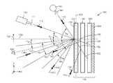
도 1은 본 발명의 예시적인 건식 소거가능한 프로젝션 시스템의 사용의 개략도.
도 2는 본 발명에서의 사용을 위한 예시적인 프로젝션 부재에 관한 수평 및 수직 이득 곡선(gain curve)들의 개략적인 선도.
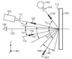
도 3은 본 발명의 예시적인 프로젝션 시스템의 사용의 개략 측면도.
도 4는 광학 확산기의 개략 측면도.
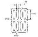
도 5는 구조화된(structured) 표면의 개략 평면도.
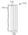
도 6은 본 발명의 예시적인 커뮤니케이션 용품의 개략 측면도.
명세서에서, 다수의 도면에 사용되는 동일한 도면 부호는 동일하거나 유사한 특성 및 기능을 갖는 동일하거나 유사한 요소를 지시한다. 도면은 축척대로 도시되지 않았으며 예시의 목적만을 위해 사용된다.The present invention may be more fully understood and appreciated by considering the following detailed description of various embodiments of the invention in conjunction with the accompanying drawings.
1 is a schematic diagram of the use of an exemplary dry erasable projection system of the present invention.
2 is a schematic diagram of horizontal and vertical gain curves for an exemplary projection member for use in the present invention.
3 is a schematic side view of the use of an exemplary projection system of the present invention.
4 is a schematic side view of an optical diffuser.
5 is a schematic plan view of a structured surface.
6 is a schematic side view of an exemplary communication article of the present invention.
In the specification, the same reference numerals used in the multiple drawings indicate the same or similar elements having the same or similar characteristics and functions. The drawings are not to scale and are used for illustrative purposes only.
본 발명의 예시적인 커뮤니케이션 용품의 개략 측면도가 도 6에 도시되어 있는데, 여기서 커뮤니케이션 용품(710)은 필기 부재(712) 및 그 후방 주 표면(716) 상의 프로젝션 부재(190)를 포함한다. 필기 부재(712) 및 프로젝션 부재(190)는 직접 접촉할 수 있는데, 예를 들어 바람직하게는 높은 광학 투명도를 갖는 중간 접착제, 프레임 또는 클립과 같은 기계적 수단 등에 의해 자기 접착식으로 함께 유지될 수 있다.A schematic side view of an exemplary communication article of the present invention is shown in FIG. 6, where the
선택되는 재료에 부분적으로 의존하여, 필기 부재는 예를 들어 코팅에 의해 프로젝션 부재의 전방 표면 상에 직접 형성될 수 있거나, 필기 부재 및 프로젝션 부재가 개별적으로 형성되고 이어서 광학 장치로 조립될 수 있다.Depending in part on the material selected, the writing member may be formed directly on the front surface of the projection member, for example by coating, or the writing member and the projection member may be formed separately and then assembled into an optical device.
본 명세서에 사용되는 바와 같이, "수직", "수평", "위", "아래", "좌측", "우측", "상부" 및 "하부", "전방" 및 "후방", "시계방향" 및 "반시계방향" 및 다른 유사한 용어와 같은 용어들은 도면에 도시된 바와 같은 상대적인 위치를 지칭한다. 일반적으로, 물리적인 실시 형태는 상이한 배향을 가질 수 있으며, 그 경우에 이 용어들은 장치의 실제 배향에 맞추어 수정되는 상대적인 위치를 지칭하도록 의도된다. 예를 들어, 도 1의 구조물이 도면의 배향과 비교하여 90°만큼 회전될지라도, 화살표 방향(130)은 여전히 "수평" 방향을 따르는 것으로 간주된다.As used herein, "vertical", "horizontal", "up", "down", "left", "right", "top" and "bottom", "front" and "rear", "clock" Terms such as "direction" and "counterclockwise" and other similar terms refer to relative positions as shown in the figures. In general, physical embodiments may have different orientations, in which case these terms are intended to refer to relative positions that are modified to the actual orientation of the device. For example, even though the structure of FIG. 1 is rotated by 90 ° relative to the orientation of the figure, the
필기 부재Writing
필기 부재(712)는 건식 소거가능한 필기 표면으로서 사용될 수 있는 전방 주 표면(714)을 갖는다. 적합한 재료는 당업자에 의해 용이하게 선택될 수 있다. 필기 부재(712)는 건식 소거가능하고 투명하여야 한다. 전형적으로, 필기 부재는 가시광에 대해 70% 이상, 바람직하게는 80% 이상의 투명도를 갖는다.The writing
잉크의 비딩(beading) 없이 필기된 표지(indicia)로서 필기 부재(712) 상에서의 잉크의 수용은 건식 소거 필기 표면의 "습윤성(wettability)"으로 정의될 수 있다. 습윤성은 용매가 건조될 때 그 형상을 유지할 수 있는 필기한 선과 관련된다. 용매의 디웨팅(dewetting)은 그 선이 소정 지점으로 이동하게 하거나 소정 지점에서 단절되게 하여, 그 필기물에 보이드(void)를 야기한다. 필기 표면의 표면 에너지가 마커 잉크의 용매의 표면 장력보다 더 큰 경우, 허용가능한 습윤성(또는 디웨팅 없는 필기물)이 달성된다. 필기 표면은 추가로, 일단 표지가 더 이상 필요 없으면 사용자가 건식 소거 마커로 필기된 표지를 (예를 들어, 마른 천 또는 건식 소거제로) 지우게 하는 소정 수준의 "소거성(erasability)"을 제공한다. 필기 표면의 표면 에너지가 필기 표면에의 마커 잉크 내의 결합제 및 다른 고형물의 강한 점착을 방지하기에 충분히 낮은 경우 허용가능한 소거성이 달성된다. 건식 소거 마커의 용매 조성물은 전형적으로 마커 상에 열거되어 있거나 마커를 위한 MSDS 상에 기록되어 있다. 건식 소거 마커를 위한 통상적인 용매는 예를 들어 에탄올, 아이소프로판올, 메틸 아이소부틸 케톤 및 n-부틸 아세테이트를 포함한다. 높은 표면 장력을 갖는 하나의 용매는 표면 장력이 약 25 mJ/m2인 n-부틸 아세테이트이다. 따라서, 일부 실시 형태에서, 건식 소거 표면은 표면 장력이 약 25 mJ/m2 이하인 용매에 의해 습윤가능할 수 있다. 일 실시 형태에서, 필기 표면의 표면 에너지는 약 25 mJ/m2 내지 약 40 mJ/m2의 범위 내이다. 다른 실시 형태에서, 필기 표면의 표면 에너지는 다인 펜 시험(Dyne Pen Test)에 의해 측정했을 때 약 30 mJ/m2 내지 약 35 mJ/m2의 범위 내이다. 본 발명의 건식 소거 용품에서, 필기 표면은 간단한 펠트(felt) 소거제로 용이하게 소거가능하다.The acceptance of ink on the writing
필기 부재(712)가 약 25 mJ/m2 이상의 표면 에너지를 갖는 것이 바람직하다. 필기 표면의 이러한 표면 에너지는 잉크가 전형적으로 건식 소거되는 것을 방지하고 영구적인 마커가 필기 표면 상에서 비딩되는 것을 방지한다. 필기된 표지는 연속 층으로서 받아들여져, 필기된 표지를 형성하는 선에서의 비딩 발생 또는 "갭(gap)"을 방지한다. 전형적인 마커 용매는 에탄올, 아이소프로판올, 메틸 아이소부틸 케톤, n-부틸 아세테이트, 에틸 아세테이트, n-프로판올 및 n-부탄올을 포함한다. 마커가 비딩 발생 없이 건식 소거 표면을 완전히 습윤시키기 위해, 건식 소거 표면의 표면 에너지는 마커 내의 용매의 표면 장력보다 커야 한다. 위의 목록에서 최고 표면 장력을 갖는 용매는 표면 장력이 약 25 mJ/m2인 n-부틸 아세테이트이다. 따라서, 일 실시 형태에서, 건식 소거 용품의 필기 표면은 약 25 mJ/m2 이상인 표면 에너지를 갖는다. 대안적인 실시 형태에서, 건식 소거 용품의 필기 표면은 다인 펜 시험에 의해 측정했을 때 약 30 mJ/m2 이상의 표면 에너지를 갖는다. 부가적으로, 필기된 표지는 바람직하게는 건식 소거 용품에 의한 최소의 와이핑(wiping) 및 최소의 잉크의 흡수(또는 "고스팅(ghosting)")로 건식 소거 용품으로부터 신속하게 제거될 수 있다. 필기 표면의 표면 에너지가 마커 잉크 내의 결합제 및 다른 고형물이 필기 표면에 강하게 점착되는 것을 방지하기에 충분히 낮은 경우 잉크의 허용가능한 제거가능성이 달성된다. 따라서, 일 실시 형태에서, 건식 소거 용품의 필기 표면은 약 40 mJ/m2 이하의 표면 에너지를 갖는다. 대안적인 실시 형태에서, 건식 소거 용품의 필기 표면은 약 35 mJ/m2 이하의 표면 에너지를 갖는다.Preferably, the writing
필기 표면에 사용하기에 적합한 재료의 예시적인 예는, 방사선 경화성 하드코트(hardcoat)로 코팅된 열가소성 수지와 열경화성 수지 둘 모두를 포함한 투명 중합체성 수지로 된 시트 및 필름이다. 사용에 적합한 중합체성 수지의 예에는 폴리에스테르, 폴리에테르, 폴리아미드, 폴리우레탄, 폴리아크릴레이트, 폴리에틸렌, 폴리프로필렌, 폴리비닐, 셀룰로오스 에스테르, 에폭시 수지, 페놀 수지 등이 포함된다. 구매가능한 가요성의 건식 소거 표면의 예시적인 예는 자외선(UV) 경화성 하드코트 필름이다. UV 경화성 하드코트를 갖는 예시적인 폴리에스테르 필름은 미국 위스콘신주 다리엔 소재의 프로텍트-올, 인크.(Protect-all, Inc.)로부터 입수가능하다. UV 경화성 하드코트 필름 건식 소거 보드는 미국 일리노이주 링컨셔 소재의 악코 월드 코포레이션(ACCO World Corporation)으로부터 구매가능하다.Illustrative examples of materials suitable for use in writing surfaces are sheets and films of transparent polymeric resin, including both thermoplastic and thermoset resins coated with radiation curable hardcoats. Examples of suitable polymeric resins for use include polyesters, polyethers, polyamides, polyurethanes, polyacrylates, polyethylene, polypropylene, polyvinyl, cellulose esters, epoxy resins, phenolic resins, and the like. An illustrative example of a commercially available flexible dry erase surface is an ultraviolet (UV) curable hardcoat film. Exemplary polyester films with UV curable hardcoats are available from Protect-all, Inc., Darien, WI. UV curable hardcoat film dry erase boards are commercially available from ACCO World Corporation, Lincolnshire, Ill.
실시 형태에 따라, 필기 부재는 전형적으로 두께가 약 0.5 내지 약 3 밀(mil)이지만, 필요한 경우 이 범위 밖에 있는 치수를 갖는 것이 사용될 수 있다. 많은 실시 형태에서, 필기 부재의 굴절률은 약 1.45 내지 약 1.70일 것이다.Depending on the embodiment, the writing member is typically about 0.5 to about 3 mils thick, but if necessary, one having a dimension outside this range can be used. In many embodiments, the refractive index of the writing member will be about 1.45 to about 1.70.
필기 부재의 전방 표면은 원하는 대로 실질적으로 매끄럽거나 약간 거칠 수 있다. 건식 소거가능한 표면의 당업자에게 알려져 있는 바와 같이, 예를 들어 엠보싱 또는 다른 적합한 수단과 같은 표면의 약간의 텍스처링(texturing) 또는 조면화(roughening)가 눈부심 감소를 달성하고 필기성 및 소거성 성능을 최적화하기 위해 사용될 수 있다. 예를 들어, 일부 실시 형태에서, 본 발명의 용품의 필기 부재의 전방 표면은 접촉 스타일러스 프로파일로미터(stylus profilometer)에 의해 측정했을 때 평균 표면 조도(roughness) Ra가 약 60 내지 약 1000의 범위일 것이다.The front surface of the writing member may be substantially smooth or slightly rough as desired. As is known to those skilled in the art of dry erasable surfaces, slight texturing or roughening of the surface, such as, for example, embossing or other suitable means, achieves glare reduction and optimizes handwriting and erasing performance. Can be used to For example, in some embodiments, the front surface of the writing member of the article of the invention may have an average surface roughness Ra of about 60 to about 1000 as measured by a contact stylus profilometer. will be.
UV 경화성 하드코트를 갖는 필름에 추가하여, UV 경화성 코팅 제형을 프로젝션 부재 상에 직접 코팅하는 것이 가능하다. 예시적인 UV 경화성 제형은 다작용성 아크릴레이트 단량체, 다작용성 우레탄 아크릴레이트 단량체, 단작용성 아크릴레이트 단량체 및 UV 개시제를 포함한다. 이들 물질에 추가하여, UV 경화성 제형은 입자 또는 소광제(flatting agent)를 포함할 수 있다. 경화된 제형의 표면 에너지는 불소 또는 실리콘 함유 단량체를 첨가함으로써 감소될 수 있다.In addition to the film with the UV curable hardcoat, it is possible to coat the UV curable coating formulation directly on the projection member. Exemplary UV curable formulations include multifunctional acrylate monomers, multifunctional urethane acrylate monomers, monofunctional acrylate monomers and UV initiators. In addition to these materials, UV curable formulations may include particles or flatting agents. The surface energy of the cured formulation can be reduced by adding fluorine or silicon containing monomers.
일 실시 형태에서, 프로젝션 스크린은 UV 경화성 하드코트 제형으로 코팅되고 이어서 UV 광으로 경화되어 건식 소거가능한 프로젝션 스크린을 형성한다.In one embodiment, the projection screen is coated with a UV curable hardcoat formulation and then cured with UV light to form a dry erasable projection screen.
프로젝션 부재Projection member
본 명세서에서 때때로 광 확산 광학 구조물로 지칭되는 프로젝션 부재(190)가 필기 부재(712)의 후방 표면(716) 상에 배치된다.A
본 발명의 용품에 사용되는 프로젝션 부재는 입사광의 비대칭 투사를 제공하여, 원하는 광, 즉 이미지 프로젝터로부터의 광을 관찰자로 방향전환시키고, 원하지 않는 광, 예를 들어 창문 또는 문, 천장의 광 등과 같은 주변 광원으로부터의 광을 관찰자로부터 멀리 방향전환시키도록 한다. 그 결과, 본 발명의 커뮤니케이션 용품은 밝게 조명된 환경에서 사용하기에 특히 적합하여, 그렇지 않으면 곤란한 환경에서 필기 및 투사된 이미지의 명료성 및 가시성을 개선시킨다.The projection member used in the article of the present invention provides an asymmetrical projection of incident light, redirecting the desired light, ie light from the image projector, to an observer, such as undesired light such as windows or doors, ceiling light, etc. Try to redirect light from the ambient light source away from the viewer. As a result, the communication article of the present invention is particularly suitable for use in brightly lit environments, improving the clarity and visibility of handwritten and projected images in otherwise difficult environments.
도 1은 일반적으로 3개의 직교축(x, y, z)을 한정하는 건식 소거가능한 프로젝션 시스템(100)의 개략 측면도이다. 프로젝션 시스템(100)은 비대칭 광학 확산기(170), 실질적으로 경면인 반사기(150) 및 광 흡수 층(160)을 포함하는, 필기 부재(712)의 후방 표면 상에 있는 광 확산 광학 구조물(190), 주변 광원(140) 및 이미지 투사 광원(110)을 포함한다.1 is a schematic side view of a dry
이미지 투사 광원(110)은 대체로 제1 방향(112)을 따라 이미지 평면(120) 상으로 이미지 광(111)을 투사한다. 제1 방향(112)은 x-축을 따르는 수평 방향(130)과 각도 θ1을 이룬다. 일부 경우에, 각도 θ1은 실질적으로 0도와 같다. 그러한 경우에, 각도 θ1은 약 20도 미만, 또는 약 15도 미만, 또는 약 10도 미만, 또는 약 5도 미만, 또는 약 3도 미만이다.The image projection
주변 광원(140), 예를 들어 방의 창문 또는 문, 천장의 조명 기구(들) 등은 수평 방향(130)과 각도 θ2를 이루는 대체로 제2 방향(142)을 따라 주변광(141)을 방출한다. 일부 경우에, 각도 θ2는 각도 θ1보다 실질적으로 크다. 그러한 경우에, 각도 θ2는 약 20도 이상, 또는 약 30도 이상, 또는 약 40도 이상, 또는 약 50도 이상, 또는 약 60도 이상, 또는 약 70도 이상만큼 각도 θ1보다 크다. 일부 경우에, 각도 θ2는 약 40도 초과, 또는 약 50도 초과, 또는 약 60도 초과, 또는 약 70도 초과이다.Ambient
비대칭 광학 확산기(170)는 상이하게 여러 방향을 따라, 예를 들어 x-방향에 평행한 수평 방향(130)을 따라 그리고 y-방향에 평행한 수직 방향(132)을 따라 입사광을 산란시킨다. 도 2는 상호 직교하는 수평 방향 및 수직 방향을 따른 비대칭 광학 확산기(170)의 각각의 수평 및 수직 이득 곡선(210, 220)의 개략 선도를 보여준다. 비대칭 광학 확산기(170)는 축상(on-axis) 또는 0도 시야각에 대응하는 최대 이득 go, 및 AH1- AH2와 동일한 수평 시야각 AH 및 AV1- AV2와 동일한 수직 시야각 AV를 한정하는 최대-반값 이득 g1= go/2를 갖는다. AH1 및 AH2는 양의 수평 시야각 및 음의 수평 시야각으로 각각 지칭될 수 있으며, AV1 및 AV2는 양의 수직 시야각 및 음의 수직 시야각으로 각각 지칭될 수 있다. 도 2의 예시적인 이득 선도에서, 이득 곡선(210, 220)의 각각은 축상 관찰 방향에 관해 대칭이다. 일반적으로, 이득 곡선(210, 220)은 축상 관찰 방향에 관해 대칭일 수 있거나 대칭이 아닐 수 있다. 예를 들어, 일부 경우에, 양의 시야각에 관해 절반-휘도 시야각에 대응하는 양의 시야각 AH1은 음의 시야각에 관해 절반-휘도 시야각에 대응하는 음의 시야각 AH2와 상이할 수 있다.Asymmetric
도 1을 다시 참조하면, 광학 확산기(170)는 비대칭 확산기이며, 이는 수평 시야각 AH가 수직 시야각 AV와 상이함을 의미한다. 일부 경우에, 비대칭 광학 확산기(170)는 제1 시야각 AH를 갖는 제1 방향, 예를 들어 수평 방향으로, 그리고 제2 시야각 AV를 갖는, 제1 방향에 직교하는 제2 방향, 예를 들어 수직 방향으로 광을 산란시킨다. 일부 경우에, AH/AV의 비는 약 2 이상, 또는 약 2.2 이상, 또는 약 2.5 이상, 또는 약 2.7 이상, 또는 약 3 이상, 또는 약 3.2 이상, 또는 약 3.5 이상, 또는 약 3.7 이상, 또는 약 4 이상이다. 일부 경우에, 수평 시야각 AH는 약 40도 이상, 또는 약 50도 이상, 또는 약 60도 이상, 또는 약 70도 이상, 또는 약 80도 이상, 또는 약 90도 이상만큼 수직 시야각 AV보다 더 크다.Referring back to FIG. 1, the
비대칭 광학 확산기(170)는 수직 방향(132)을 따라 이미지 평면(120)에 배치된다. 비대칭 확산기(170)는 이미지 광(111)을 수광하고 그 이미지 광을 산란시켜 대체로 제2 방향(114)을 따라 전파되는 산란된 이미지 광(113)을 형성한다. 일부 경우에, 방향(112, 114)들은 x-축에 관해 대칭이다. 그러한 경우에, 제2 방향(114)은 수평 방향(130)과 각도 θ1을 이룬다. 일부 경우에, 산란된 이미지 광(113)은 수평 방향(130)과 각도 αV를 이루는 원하는 관찰 위치(180)를 포함하거나 포괄하는 수직 이미지 광 원추(115)를 갖는다.Asymmetric
비대칭 확산기(170)는 주변광(141)을 수광하고 그 주변광을 산란시켜 대체로 제4 방향(144)을 따라 전파되는 산란된 주변광(143)을 형성한다. 일부 경우에, 방향(142, 144)들은 수평 방향(130)에 관해 대칭이다. 그러한 경우에, 제4 방향(144)은 수평 방향(130)과 각도 θ2를 이룬다. 일부 경우에, 산란된 주변광(143)은 원하는 관찰 위치(180)를 포함하지 않거나 포괄하지 않는 수직 주변광 원추(145)를 갖는다.The
일부 경우에, 관찰 위치(180)는 수직 이미지 광 원추(115) 내에 포함되거나 위치되지만, 수직 주변광 원추(145) 내에는 포함되거나 위치되지 않는다. 그러한 경우에, 관찰 위치(180)의 관찰자는 고콘트라스트를 갖는 이미지를 볼 수 있는데, 그 이유는 그러한 이미지는 주변 광원(140)으로부터 유래하는 주변광을 포함하지 않거나 아주 조금 포함하기 때문이다. 일부 경우에, 비대칭 확산기(170)의 수직 시야각은 수직 이미지 광 원추(115)가 관찰 위치(180)를 포함하거나 포괄할 정도로 충분히 크고, 수직 주변광 원추(145)가 관찰 위치(180)를 포함하지 않을 정도로 충분히 작다.In some cases,
일부 경우에, 예를 들어 각도 αV가 도 3에 개략적으로 도시된 바와 같이 실질적으로 0도와 동일할 때, 비대칭 확산기(170)에 의해 산란된 이미지 광은 관찰 위치(180)에 도달하고, 확산기에 의해 산란된 주변광은 그 관찰 위치로부터 멀리 전파된다. 그러한 경우에, 확산기(170)의 절반 수직 시야각(AV/2)은 θ1보다 크고 θ2보다 작다. 그러한 경우에, 관찰 위치(180)의 관찰자는 향상된 콘트라스트를 갖는 디스플레이된 이미지를 관찰한다.In some cases, for example, when the angle αV is substantially equal to zero degrees as shown schematically in FIG. 3, the image light scattered by the
반사기(150)는 광학 확산기(170)에 의해 산란되지 않은 이미지 광(155)을 반사한다. 일부 경우에, 반사기(150)는 실질적으로 경면 반사기이다. 그러한 경우에, 반사기(150)에 의해 반사되는 전체 광 중 상당한 부분이 경면 반사되고, 전체 반사된 광 중 작은 부분만이 확산 반사된다. 예를 들어, 그러한 경우에, 가시 파장에서 반사기(150)의 전체 반사율에 대한 경면 반사율의 비는 약 0.7 이상, 또는 약 0.75 이상, 또는 약 0.8 이상, 또는 약 0.85 이상, 또는 약 0.9 이상, 또는 약 0.95 이상이며, 여기서 가시 파장은 전자기 스펙트럼의 가시 범위 내의 임의의 파장일 수 있다. 일부 경우에, 가시 범위는 약 400 nm 내지 약 690 nm, 또는 약 410 nm 내지 약 680 nm, 또는 약 420 nm 내지 약 670 nm이다.
반사기(150)는 이미지 광(155)을, 수평 방향과 각도 θ1을 이루는 제5 방향(152)을 따라 반사된 이미지 광(151)으로서 경면 반사한다. 반사기(150)는 광학 확산기(170)에 의해 산란되지 않은 주변광(156)을 반사한다. 반사기(150)는 주변광(156)을, 수평 방향과 각도 θ2를 이루는 제6 방향(154)을 따라 반사된 주변광(153)으로서 경면 반사한다. 일부 경우에, 관찰 위치(180), 이미지 투사 광원(110) 및 주변 광원(140)의 위치들은, 관찰 위치(180)의 관찰자가 반사된 이미지 광(151)을 받아 보지만 반사된 주변광(153)을 받아 보지는 않게 되어 있다. 그러한 경우에, 경면 반사기(150)는 비대칭 광학 확산기(170)에 의해 산란되지 않은 이미지 광(155)을 관찰 위치를 향해 반사하고, 비대칭 광학 확산기(170)에 의해 산란되지 않은 주변광(156)을 관찰 위치로부터 멀리 반사한다. 그러한 경우에, 관찰 위치(180)에 위치한 관찰자는 증가된 콘트라스트를 갖는 이미지를 관찰할 수 있다.The
일부 경우에, 경면 반사기(150)의 반사율은 입사각이 증가함에 따라 변하지 않거나 매우 조금 변한다. 그러한 경우에, 경면 반사기(150)는 약 θ1의 입사각의 가시광에서 제1 평균 반사율 R1, 및 약 θ2의 입사각의 가시광에서 제2 평균 반사율 R2를 가지는데, 여기서 R1과 R2 사이의 차이는 약 10% 이하, 또는 약 5% 이하, 또는 약 2% 이하이다. 일부 경우에, 각도 θ1은 약 0도이고, 각도 θ2는 약 45도이다.In some cases, the reflectance of the
일부 경우에, 경면 반사기(150)의 반사율은 입사각이 증가함에 따라 변하는데, 예를 들어 감소한다. 일부 경우에, 예를 들어 각도 θ1이 각도 θ2보다 실질적으로 작을 때, 입사각이 증가함에 따라 반사율이 감소하는 반사기(150)는 관찰 위치(180)와 같은 관찰 위치로 디스플레이되는 이미지의 콘트라스트를 증가시킬 수 있다. 일부 경우에, 경면 반사기(150)는 약 θ1의 입사각의 가시광에서 제1 평균 반사율 R1, 및 약 θ2의 입사각의 가시광에서 제2 평균 반사율 R2를 가지는데, 여기서 R1/R2의 비는 약 1.2 이상, 또는 약 1.4 이상, 또는 약 1.5 이상, 또는 약 1.6 이상, 또는 약 1.8 이상, 또는 약 2 이상, 또는 약 2.5 이상, 또는 약 3 이상이다. 일부 경우에, 각도 θ1은 약 0도이고, 각도 θ2는 약 45도이다.In some cases, the reflectance of the
일부 경우에, 경면 반사기(150)는 전자기 스펙트럼의 가시 영역과 같은 영역에서 실질적으로 평평한 반사율 스펙트럼을 가질 수 있다. 예를 들어, 그러한 경우에, 경면 반사기의 반사율은 가시광에서 20% 이하만큼, 또는 15% 이하만큼, 또는 10% 이하만큼, 또는 5% 이하만큼 변한다. 일부 경우에, 청색 파장, 예를 들어 440 nm에서의 반사기(150)의 반사율과 적색 파장, 예를 들어 620 nm에서의 반사율의 비는 약 0.8 내지 약 1.2의 범위, 또는 약 0.9 내지 약 1.1의 범위 내이다.In some cases, the
일반적으로, 경면 반사기(150)는 소정 응용에 바람직하고 그리고/또는 실용적일 수 있는 임의의 경면 반사기일 수 있다. 예를 들어, 경면 반사기(150)는 알루미늄 도금 필름 또는 다층 중합체성 반사 필름, 예를 들어 반사 편광 필름 또는 미국 미네소타주 세인트 폴 소재의 쓰리엠 컴퍼니(3M Company)로부터 입수가능한 비퀴티(VIKUITI)™ ESR 필름일 수 있다.In general, the
광 흡수 층(160)은 경면 반사기(150)에 의해 반사되지 않은 이미지 광(161) 및 주변광(162)을 흡수함으로써 디스플레이되는 이미지의 콘트라스트를 증가시킬 수 있다. 광 흡수 층(160)은 소정 응용에 바람직하고 그리고/또는 실용적일 수 있는 임의의 광 흡수 재료를 포함할 수 있다. 예를 들어, 층(160)은 카본 블랙, 흑색 염료 또는 다른 어두운 색의 염료와 같은 광 흡수성 염료, 광 흡수성 안료 또는 다른 어두운 색의 안료, 또는 불투명 입자 - 결합제 재료에 분산됨 - 를 포함할 수 있다. 적합한 결합제는 열가소성 물질, 방사선 경화성 또는 열경화성 아크릴레이트, 에폭시, 실리콘계 재료, 또는 다른 적합한 결합제 재료를 포함한다. 일부 경우에, 가시광에서의 광 흡수 층(160)의 광학 흡수 계수는 약 0.1 마이크로미터-1 이상, 또는 약 0.2 마이크로미터-1 이상, 또는 약 0.4 마이크로미터-1 이상, 또는 약 0.6 마이크로미터-1 이상이다.The light
이미지 투사 광원(110)은 이미지 형성 장치를 포함하며, 이 장치에 의해 형성된 이미지를 디스플레이 또는 이미지 평면(120) 상으로 투사한다. 프로젝터(110)의 출력 광(111)은 소정 응용에 바람직할 수 있는 임의의 편광을 가질 수 있다. 예를 들어, 일부 경우에, 출력 광(111)은 실질적으로 비편광된다. 그러한 경우에, 제1 편광 상태를 갖는 출력 광(111)의 세기(intensity)와 제1 편광 상태에 수직한 제2 편광 상태를 갖는 출력 광의 세기의 비는 약 0.8 내지 약 1.2, 또는 약 0.85 내지 약 1.15, 또는 약 0.9 내지 약 1.1, 또는 약 0.95 내지 약 1.05의 범위 내이다. 일부 경우에, 출력 광(111)은 예를 들어 제1 방향을 따라 실질적으로 편광된다. 그러한 경우에, 제1 편광 상태를 갖는 출력 광(111)의 세기 대 직교하는 편광 상태를 갖는 출력 광의 세기의 비는 약 100 이상, 또는 약 500 이상, 또는 약 1000 이상이다. 일부 경우에, 출력 광(110)은 편광 상태들의 혼합을 포함한다. 예를 들어, 일부 경우에, 출력 광(110)은 적색, 녹색 및 청색 광을 포함할 수 있으며, 여기서 청색 광 및 적색 광은 하나의 편광 상태를 가지며 녹색 광은 직교하는 편광 상태를 갖는다.The image projection
일반적으로, 이미지 투사 광원(110)은 임의의 이미지 형성 장치를 포함할 수 있다. 예를 들어, 이미지 형성 장치는 반사형 디스플레이, 투과형 디스플레이, 또는 발광형 디스플레이(emissive display), 또는 반투과형 디스플레이(transflective display)와 같은 여러 디스플레이 유형들의 조합일 수 있다. 예를 들어, 일부 경우에, 반사형 이미지 형성 장치는 LCD 또는 디지털 마이크로-미러 어레이 디스플레이(digital micro-mirror array display), 예를 들어 텍사스 인스트루먼츠, 인크.(Texas Instruments, Inc.)의 디지털 라이트 프로세서(Digital Light Processor, DLP)를 포함할 수 있다.In general, image projection
일반적으로, 비대칭 광학 확산기(170)는 소정 응용에서 바람직하고 그리고/또는 실용적일 수 있는 임의의 비대칭 확산기일 수 있다. 예를 들어, 비대칭 확산기(170)는 벌크 확산기(bulk diffuser) 및/또는 표면 확산기일 수 있다. 벌크 확산은 예를 들어 호스트 재료(host material)에 게스트 재료(guest material)의 작은 입자를 포함시키거나 분산시킴으로써 달성될 수 있는데, 여기서 게스트 재료 및 호스트 재료는 상이한 굴절률을 갖는다. 표면 확산은 예를 들어 확산기의 표면을 무광택(matte)으로 만듦으로써 달성될 수 있다.In general, asymmetric
일부 경우에, 확산기(170)는 벌크 확산기이며, 게스트 재료와 호스트 재료의 굴절률들 사이의 차이는 약 0.01 이상, 또는 약 0.02 이상, 또는 약 0.03 이상, 또는 약 0.04 이상이다. In some cases,
일부 경우에, 비대칭 광학 확산기(170)는 실질적으로 편광-무의존성(polarization-insensitive)일 수 있다. 그러한 경우에, 주어진 방향, 예를 들어 수평 방향을 따른 상호 직교 편광된 2개의 입사광에 관한 비대칭 광학 확산기의, 수평 이득 곡선(210)들과 같은 이득 곡선들은 실질적으로 동일하다. 예를 들어, 그러한 경우에, 수평 방향을 따른 상호 직교 편광된 2개의 입사광에 관한 수평 이득 곡선(210)들은 약 15% 이하만큼, 또는 약 10% 이하만큼, 또는 약 5% 이하만큼 차이가 있다. 다른 예로서, 수직 방향을 따른 상호 직교 편광된 2개의 입사광에 관한 수직 이득 곡선(220)들은 약 15% 이하만큼, 또는 약 10% 이하만큼, 또는 약 5% 이하만큼 차이가 있다.In some cases, asymmetric
일부 경우에, 비대칭 광학 확산기(170)는 구조화된 표면 또는 층을 포함할 수 있다. 구조화된 층은 소정 응용에 바람직할 수 있는 임의의 형상을 갖는 구조체를 포함할 수 있다. 예시적인 형상에는 평탄한 형상, 오목한 형상, 볼록한 형상, 비구면 형상, 프레넬(Fresnel) 형상, 타원체 형상, 피브릴(fibril) 형상, 회절 형상, 및 다면형(faceted) 형상이 포함된다. 예를 들어, 도 4는 피치(430)를 갖는 마이크로렌즈(420)들과 같은 복수의 광학 렌즈를 포함하는 구조화된 표면(410)을 포함하는 비대칭 광학 확산기(470)의 개략 측면도이다. 일부 경우에, 광학 렌즈들 중 적어도 일부는 예를 들어 이미지 투사 광원(110)에 의해 투사되는 이미지의 종횡비를 변경하기 위해 왜상형(anamorphic)일 수 있다. 일부 경우에, 왜상형 렌즈는 원통형과 같이 긴 렌즈일 수 있거나 이를 포함할 수 있다. 일부 경우에, 비대칭 광학 확산기(170)는 랜덤 피치(random pitch)(430)를 갖는 원통형 렌즈들의 어레이(array)와 같은 긴 광학 렌즈들의 어레이를 포함할 수 있다. 도 5는 복수의 렌즈릿(lenslet)(620)을 포함하는, 구조화된 표면(410)과 유사한 구조화된 표면(610)의 개략 평면도이다. 각각의 렌즈릿은 폭 a1, 길이 a2, 및 종횡비 a2/a1를 갖는다. 일부 경우에, 종횡비는 약 1.5 내지 약 200, 또는 약 2 내지 약 100, 또는 약 2 내지 약 50, 또는 약 2 내지 약 25의 범위 내이다.In some cases, asymmetric
일부 경우에, 비대칭 광학 확산기(170)는 벌크 확산기이고, 제2 재료 내에 있는 제1 재료로 된 복수의 긴 구조체 또는 입자를 포함하며, 여기서 두 재료는 상이한 굴절률을 갖는다. 일부 경우에, 긴 입자는 일반적으로 동일한 방향을 따라, 예를 들어 수직 방향(132)을 따라 배향된다. 일부 경우에, 긴 입자의 길이는 약 50 nm 내지 약 100 마이크로미터, 또는 약 100 nm 내지 약 50 마이크로미터, 또는 약 200 nm 내지 약 10 마이크로미터의 범위 내이다. 일부 경우에, 긴 입자의 종횡비는 약 5:1 내지 약 1000:1, 또는 약 10:1 내지 약 200:1, 또는 약 20:1 내지 약 50:1의 범위 내이다.In some cases, asymmetric
일부 경우에, 광학 구조물(190)은 통합된 구조물이며, 이는 그 구조물 내의 개개의 구성요소들이 예를 들어 하나 이상의 접착제 층에 의해 서로 부착됨을 의미한다.In some cases,
일부 경우에, 용품은 선택적인 기재(185)를 추가로 포함할 수 있다. 일부 경우에, 기재(185)는 용품 내의 다른 구성요소에 지지를 주로 제공할 수 있다. 일부 경우에, 기재(185)는 하나 이상의 추가적인 광학 기능을 제공할 수 있다. 예를 들어, 기재(185)는 광학 확산기, 광대역 광 흡수기, 흡수 편광기, 반사 편광기, 또는 소정 응용에 바람직할 수 있는 기능을 갖는 임의의 다른 필름일 수 있거나 이들을 포함할 수 있다. 기재(185)는 소정 응용에 적합한 그리고/또는 실용적일 수 있는 임의의 재료, 예를 들어 폴리에틸렌 테레프탈레이트(PET), 폴리비닐클로라이드(PVC), 폴리카르보네이트, 아크릴, 알루미늄 시트, 유리, 및 이들의 복합물일 수 있다.In some cases, the article may further include an
개시된 시스템 및 구조물들의 이점들 중 일부가 하기의 실시예에 의해 추가로 예시된다. 이 실시예에서 언급되는 구체적인 재료, 양 및 치수뿐만 아니라 다른 조건 및 상세 사항은 본 발명을 부당하게 제한하는 것으로 해석되어서는 안된다.Some of the advantages of the disclosed systems and structures are further illustrated by the following examples. The specific materials, amounts and dimensions as well as other conditions and details mentioned in this example should not be construed as unduly limiting the invention.
실시예Example
건식 소거 층을 형성하기 위해, 하드코트 조성물을 미국 특허 제6,299,799호의 실시예 3에 따라 제조하였다. 조성물은 메타크릴로일옥시프로필트라이메톡시실란(아크릴레이트 실란)으로 표면 개질된 18.4 중량%의 20 nm 실리카 입자(날코(NALCO)™ 2327), 25.5 중량%의 펜타에르트리톨 트라이/테트라 아크릴레이트(PETA), 4.0 중량%의 N,N-다이메틸아크릴아미드(DMA), 1.2 중량%의 이르가큐어(IRGACURE)™ 184, 1.0 중량%의 티누빈(TINUVIN)™ 292 , 46.9 중량%의 용매 아이소프로판올, 및 3.0 중량%의 물을 포함하였다. 이어서 중량 기준으로 대략 50% 고형물이었던 조성물을 용매 1-메톡시 2-프로판올/에틸 아세테이트(1:4의 v/v비)로 30 중량% 고형물까지 희석하였다.To form a dry erase layer, a hardcoat composition was prepared according to Example 3 of US Pat. No. 6,299,799. The composition is 18.4 wt% 20 nm silica particles (NALCO ™ 2327), 25.5 wt% pentaertritol tri / tetra acryl surface modified with methacryloyloxypropyltrimethoxysilane (acrylate silane) PETA, 4.0 wt% N, N-dimethylacrylamide (DMA), 1.2 wt% IRGACURE ™ 184, 1.0 wt% TINUVIN ™ 292, 46.9 wt% Solvent isopropanol, and 3.0 wt% water. The composition, which was approximately 50% solids by weight, was then diluted to 30 wt% solids with solvent 1-methoxy 2-propanol / ethyl acetate (v / v ratio of 1: 4).
100 g의 상기 코팅 용액에, 1.8 g의 실리카 비드(bead)(에보닉 인더스트리즈(Evonik Industries)로부터의 데구사(DEGUSSA)™ OK607) 및 0.03 g의 테고(TEGO)(등록상표)rad 2250(에보닉 인더스트리즈)을 함께 혼합하여 균질의 용액을 형성하였다.In 100 g of the coating solution, 1.8 g of silica beads (DEGUSSA ™ OK607 from Evonik Industries) and 0.03 g of TEGO®rad 2250 ( Evonik Industries) were mixed together to form a homogeneous solution.
이어서 생성된 용액을 (미국 뉴욕주 웹스터 소재의 알디 스페셜티즈(RD Specialties)로부터 획득된) #10 와이어-권취된 로드(wire-wound rod)를 사용하여 멜리넥스(MELINEX)™ 618 프라이밍된 PET 필름들의 상부에 각각 적용하였다. 이어서 생성된 필름을 오븐 안에서 85℃에서 1분 동안 건조시키고, 그 다음에 0.15 m/s (30 피트/분)의 선속도(1 패스(pass))로 100% 램프 출력에서 질소 분위기 하에서 작동하는, H-전구를 갖춘 퓨전 유브이-시스템즈 인크.(Fusion UV-Systems Inc.)(미국 메릴랜드주 게이더스버그 소재)의 라이트-해머(Light-Hammer) 6 UV 프로세서를 사용하여 경화시켰다. 생성된 코팅의 T% /H%는 90.1% 및 47.6%이다.The resulting solution was then MELINEX ™ 618 primed PET film using a # 10 wire-wound rod (obtained from RD Specialties, Webster, NY). Each was applied at the top of the field. The resulting film is then dried in an oven at 85 ° C. for 1 minute and then operated under nitrogen atmosphere at 100% lamp power at a linear speed (1 pass) of 0.15 m / s (30 feet / minute). Cured using a Light-Hammer 6 UV processor from Fusion UV-Systems Inc. (Gaithersburg, MD) with H-bulb. T% / H% of the resulting coating is 90.1% and 47.6%.
다양한 양의 테고(등록상표)rad 2250을 첨가하여 다양한 코팅 용액을 제조하였다. 지시된 마커로 필름 상에 필기함으로써 건식-소거 특성을 측정하였고 이어서 마른 천을 사용하여 지웠다. 그 결과가 표 1에 요약되어 있다.Various coating solutions were prepared by adding various amounts of Tego® rad 2250. Dry-erase properties were measured by writing on the film with the indicated markers and then erased using a dry cloth. The results are summarized in Table 1.

이상에서 언급된 모든 특허, 특허 출원 및 다른 공보들은 상세히 재현한 것처럼 본 문헌에 참고로 포함된다. 본 발명의 특정의 실시예가 본 발명의 다양한 태양의 설명을 용이하게 하기 위해 위에서 상세히 기술되었지만, 본 발명을 실시예의 상세 사항으로 제한하고자 하는 것이 아님을 알아야 한다. 오히려, 본 발명은 첨부된 특허청구범위에 의해 한정되는 본 발명의 사상 및 범주 내에 속하는 모든 수정, 실시 형태 및 대안을 포함하고자 한다.All patents, patent applications, and other publications mentioned above are incorporated herein by reference as if reproduced in detail. While certain embodiments of the invention have been described in detail above to facilitate describing various aspects of the invention, it should be understood that they are not intended to limit the invention to the details of the embodiments. Rather, the invention is intended to embrace all modifications, embodiments, and alternatives falling within the spirit and scope of the invention as defined by the appended claims.
Claims (24)
Translated fromKorean(a) 전방 주 표면 및 후방 주 표면(major surface)을 갖는 필기 부재(writing member) - 상기 전방 주 표면은 건식 소거 표면(dry erase surface)으로서 사용될 수 있으며, 상기 필기 부재는 실질적으로 투명함 - ; 및
(b) 상기 필기 부재의 상기 후방 주 표면 상에 배치되는 프로젝션 부재(projection member)를 포함하며,
상기 프로젝션 부재는
(1) 제1 시야각 AH를 갖는 제1 방향으로, 그리고 제2 시야각 AV를 갖는, 제1 방향에 직교하는 제2 방향으로 광을 산란시키는 비대칭 광학 확산기 - AH/AV는 약 2 이상임 - , 및
(2) 비대칭 광학 확산기에 의해 산란되지 않은 광을 반사하는 실질적으로 경면인 반사기를 포함하는 용품.As a communication article,
(a) a writing member having a front major surface and a back major surface, wherein the front major surface can be used as a dry erase surface, the writing member being substantially transparent ; And
(b) a projection member disposed on the rear major surface of the writing member,
The projection member
(1) an asymmetric optical diffuser that scatters light in a first direction having a first viewing angle AH and in a second direction orthogonal to the first direction having a second viewing angle AV —AH / AV is about 2 More than-, and
(2) An article comprising a substantially specular reflector that reflects light that is not scattered by the asymmetric optical diffuser.
대체로 제1 방향을 따라 이미지 평면 상으로 이미지 광을 투사하는 이미지 투사 광원 - 제1 방향은 수평 방향과 각도 θ1을 이룸 - ;
수평 방향과 각도 θ2를 이루는 대체로 제2 방향을 따라 주변광을 방출하는 주변 광원;
이미지 평면에 배치되며, 수평 방향을 따라 제1 시야각 AH 및 수평 방향에 직교하는 수직 방향을 따라 제2 시야각 AV를 갖는 비대칭 광학 확산기 - AH/AV는 약 2 이상이며, AV/2는 θ1보다 크고 θ2보다 작음 - ; 및
비대칭 광학 확산기에 의해 산란되지 않은 광을 반사하며, 약 θ1의 입사각의 가시광에서 제1 평균 반사율 R1, 및 약 θ2의 입사각의 가시광에서 제2 평균 반사율 R2를 갖는 실질적으로 경면인 반사기 - R1/R2은 약 1.5 이상임 - 를 포함하는 프로젝션 시스템.Communication article of claim 1;
An image projection light source that projects image light onto the image plane generally along the first direction, the first direction being at an angle θ1 with the horizontal direction;
An ambient light source emitting ambient light along a second direction, the angle θ2 being in a horizontal direction;
Asymmetric optical diffuser disposed in the image plane and having a first viewing angle AH along the horizontal direction and a second viewing angle AV along the vertical direction orthogonal to the horizontal direction-AH / AV is at least about 2, and AV / 2 is greater than θ1 and less than θ2- ; And
And reflecting the non-scattered light by asymmetric optical diffuser, in the visible light of an incident angle of approximately θ1 first average reflectivity R1, and a substantially mirror surface of the reflector in the visible light of the incident angle of about θ2 has a second average reflectivity R2 A projection system comprising: R1 / R2 is at least about 1.5.
Applications Claiming Priority (4)
| Application Number | Priority Date | Filing Date | Title |
|---|---|---|---|
| US14327509P | 2009-01-08 | 2009-01-08 | |
| US61/143,275 | 2009-01-08 | ||
| US17099309P | 2009-04-20 | 2009-04-20 | |
| US61/170,993 | 2009-04-20 |
Publications (1)
| Publication Number | Publication Date |
|---|---|
| KR20110122674Atrue KR20110122674A (en) | 2011-11-10 |
Family
ID=42311478
Family Applications (1)
| Application Number | Title | Priority Date | Filing Date |
|---|---|---|---|
| KR1020117018205AWithdrawnKR20110122674A (en) | 2009-01-08 | 2010-01-08 | Dry erasable projection supplies and systems |
Country Status (6)
| Country | Link |
|---|---|
| US (1) | US8220932B2 (en) |
| EP (1) | EP2385904A1 (en) |
| JP (1) | JP2012514774A (en) |
| KR (1) | KR20110122674A (en) |
| CN (1) | CN102405142A (en) |
| WO (1) | WO2010081006A1 (en) |
Families Citing this family (16)
| Publication number | Priority date | Publication date | Assignee | Title |
|---|---|---|---|---|
| CN102667618B (en) | 2009-11-23 | 2015-02-25 | 3M创新有限公司 | Front projection screen with high contrast |
| US9180724B2 (en)* | 2011-01-20 | 2015-11-10 | Crayola, Llc | Dry-erase drawing sheet and apparatus |
| US8556637B2 (en)* | 2011-10-25 | 2013-10-15 | Corning Incorporated | Method and apparatus for forming a writable erasable area on an object |
| KR102041176B1 (en)* | 2011-12-29 | 2019-11-07 | 쓰리엠 이노베이티브 프로퍼티즈 컴파니 | Cleanable articles and methods for making and using same |
| JP6102194B2 (en)* | 2012-11-09 | 2017-03-29 | 船井電機株式会社 | Projector and projection screen |
| US8915002B2 (en) | 2013-01-31 | 2014-12-23 | 3M Innovative Properties Company | Self illuminated signage for printed graphics |
| US20140256210A1 (en)* | 2013-03-08 | 2014-09-11 | Michael Scott Johnson | Connectable panel toy with erasable surfaces |
| US9082326B2 (en) | 2013-05-02 | 2015-07-14 | 3M Innovative Properties Company | Self illuminated shaped and two-sided signage for printed graphics |
| US9070312B2 (en) | 2013-11-05 | 2015-06-30 | 3M Innovative Properties Company | Hybrid self illuminated and actively back lit signage for printed graphics |
| CN103744221B (en)* | 2013-12-12 | 2017-01-04 | 中国电子科技集团公司第五十五研究所 | Improve the method displayed contrast under display strong light environment |
| JPWO2015098685A1 (en)* | 2013-12-27 | 2017-03-23 | コニカミノルタ株式会社 | Optical film, polarizing plate and image display device |
| BE1021935B1 (en)* | 2014-06-03 | 2016-01-27 | Polyvision Naamloze Vennootschap | PROJECTION AND COMMUNICATION BOARD AND METHOD OF MANUFACTURING |
| CN105223766A (en)* | 2014-07-04 | 2016-01-06 | 中强光电股份有限公司 | Projection screen and manufacturing method thereof |
| JP2017530383A (en)* | 2014-07-30 | 2017-10-12 | コーニング インコーポレイテッド | High contrast glass-based writable / erasable front projection screen |
| CN109976082B (en)* | 2017-12-14 | 2021-11-23 | 台湾扬昕股份有限公司 | Projection screen and light absorption film |
| CN110262179B (en)* | 2018-03-12 | 2025-09-12 | 姚苏栩 | Smart projection writing whiteboard |
Family Cites Families (70)
| Publication number | Priority date | Publication date | Assignee | Title |
|---|---|---|---|---|
| US3549463A (en) | 1968-06-21 | 1970-12-22 | Riegel Paper Corp | Universal graphic display material having an embossed polyvinyl fluoride surface layer |
| JPS49109037A (en)* | 1973-02-19 | 1974-10-17 | ||
| US4068922A (en) | 1976-10-01 | 1978-01-17 | The Singer Company | Front projection screen |
| IL99916A0 (en) | 1991-10-31 | 1992-08-18 | Opher Berkman | Board for screening and writing and a method for the production thereof |
| US5361164A (en) | 1992-06-17 | 1994-11-01 | Walltalkers | Projection markerboard |
| US5339198A (en) | 1992-10-16 | 1994-08-16 | The Dow Chemical Company | All-polymeric cold mirror |
| AU6812994A (en) | 1993-07-27 | 1995-02-28 | Physical Optics Corporation | Light source destructuring and shaping device |
| US6123877A (en)* | 1994-12-28 | 2000-09-26 | Nashua Corporation | Asymmetric light diffusing material |
| US6072551A (en) | 1996-02-14 | 2000-06-06 | Physical Optics Corporation | Backlight apparatus for illuminating a display with controlled light output characteristics |
| US5867316A (en) | 1996-02-29 | 1999-02-02 | Minnesota Mining And Manufacturing Company | Multilayer film having a continuous and disperse phase |
| BR9707766A (en) | 1996-02-29 | 1999-07-27 | Minnesota Mining & Mfg | Optical body |
| JP3339334B2 (en)* | 1996-12-05 | 2002-10-28 | 松下電器産業株式会社 | Reflective liquid crystal display |
| US5903392A (en) | 1997-05-19 | 1999-05-11 | Dai Nippon Printing Co., Ltd. | Reflecting screen |
| US6446467B1 (en) | 1997-07-29 | 2002-09-10 | Physical Optics Corporation | Monolithic glass light shaping diffuser and method for its production |
| US5976686A (en) | 1997-10-24 | 1999-11-02 | 3M Innovative Properties Company | Diffuse reflective articles |
| US6497946B1 (en) | 1997-10-24 | 2002-12-24 | 3M Innovative Properties Company | Diffuse reflective articles |
| JP3332211B2 (en) | 1998-01-07 | 2002-10-07 | 株式会社きもと | Reflective screen for projector |
| TW386175B (en) | 1998-05-19 | 2000-04-01 | Dainippon Printing Co Ltd | Light reflective panel for reflective liquid crystal panel |
| US6352759B2 (en) | 1998-08-20 | 2002-03-05 | Physical Optics Corporation | Non-lambertian glass diffuser and method of making |
| US6067266A (en) | 1998-11-12 | 2000-05-23 | Donelan; James P. | Erasable board kit |
| US6529322B1 (en) | 1999-01-27 | 2003-03-04 | University Of Georgia Research Foundation, Inc. | High contrast front and rear viewing surfaces for projection displays |
| JP2000221601A (en) | 1999-02-03 | 2000-08-11 | Dainippon Printing Co Ltd | Light diffusing screen |
| US6530664B2 (en)* | 1999-03-03 | 2003-03-11 | 3M Innovative Properties Company | Integrated front projection system with enhanced dry erase screen configuration |
| US6381068B1 (en) | 1999-03-19 | 2002-04-30 | 3M Innovative Properties Company | Reflective projection screen and projection system |
| US6299799B1 (en) | 1999-05-27 | 2001-10-09 | 3M Innovative Properties Company | Ceramer compositions and antistatic abrasion resistant ceramers made therefrom |
| US6476965B1 (en) | 1999-12-17 | 2002-11-05 | Avery Dennison Corporation | Dry erasable and projection articles and methods of making the same |
| US6819486B2 (en)* | 2001-01-17 | 2004-11-16 | 3M Innovative Properties Company | Projection screen having elongated structures |
| WO2002077672A2 (en)* | 2001-02-07 | 2002-10-03 | Corning Incorporated | High-contrast screen with random microlens array |
| KR100421002B1 (en) | 2001-03-07 | 2004-03-03 | 삼성전자주식회사 | Reflection type projection screen |
| JP2003075920A (en) | 2001-06-19 | 2003-03-12 | Teijin Ltd | Image display screen and image display unit |
| JP2003091002A (en)* | 2001-07-12 | 2003-03-28 | Alps Electric Co Ltd | Liquid crystal display device |
| US6847483B2 (en) | 2001-12-21 | 2005-01-25 | Bose Corporation | Selective reflecting |
| JP2003270725A (en) | 2002-03-14 | 2003-09-25 | Sony Corp | Screen for projection and method of manufacturing the same |
| US6724529B2 (en)* | 2002-04-17 | 2004-04-20 | Howard Sinkoff | Reflection-type projection screens |
| KR20040010328A (en) | 2002-07-24 | 2004-01-31 | 소니 가부시끼 가이샤 | Projection screen and its manufacturing method |
| AU2003261888A1 (en) | 2003-05-26 | 2004-12-13 | Sharp Kabushiki Kaisha | Reflection type screen |
| DE602004018231D1 (en) | 2003-06-10 | 2009-01-22 | Dainippon Printing Co Ltd | Projection screen and projection system |
| JP2005031502A (en)* | 2003-07-09 | 2005-02-03 | Sony Corp | Screen |
| JP2005107096A (en) | 2003-09-30 | 2005-04-21 | Dainippon Printing Co Ltd | Projection screen and projection system including the same |
| US7110175B2 (en) | 2004-02-27 | 2006-09-19 | Bose Corporation | Display screens |
| JP2005266264A (en)* | 2004-03-18 | 2005-09-29 | Sony Corp | Screen |
| US7408709B2 (en) | 2004-03-18 | 2008-08-05 | Sony Corporation | Screen and method for manufacturing the same |
| JP4749011B2 (en) | 2004-04-09 | 2011-08-17 | 直史 山内 | Screen and image projection system using the same |
| JP4238782B2 (en)* | 2004-06-08 | 2009-03-18 | ソニー株式会社 | Light diffusing film, method for producing the same, and screen |
| US7399184B2 (en) | 2004-07-02 | 2008-07-15 | 3M Innovative Properties Company | Dry erase article |
| WO2006017585A1 (en) | 2004-08-04 | 2006-02-16 | Fusion Optix, Inc. | Multi-region light scattering element |
| WO2006020583A2 (en) | 2004-08-10 | 2006-02-23 | Fusion Optix, Inc. | Imaging material with improved contrast |
| US7453635B2 (en) | 2004-08-10 | 2008-11-18 | Fusion Optix Inc. | Imaging material with improved contrast |
| WO2006026743A1 (en) | 2004-08-31 | 2006-03-09 | Fusion Optix, Inc. | Enhanced light diffusing sheet |
| US7278775B2 (en) | 2004-09-09 | 2007-10-09 | Fusion Optix Inc. | Enhanced LCD backlight |
| WO2006032002A1 (en) | 2004-09-13 | 2006-03-23 | Fusion Optix, Inc. | High contrast optical path corrected screen |
| US7431489B2 (en) | 2004-11-17 | 2008-10-07 | Fusion Optix Inc. | Enhanced light fixture |
| WO2006055873A2 (en) | 2004-11-17 | 2006-05-26 | Fusion Optix, Inc. | Enhanced electroluminescent sign |
| JP5250933B2 (en)* | 2005-02-02 | 2013-07-31 | 大日本印刷株式会社 | Reflective screen and method of manufacturing reflective screen |
| CN101697058B (en)* | 2005-02-02 | 2011-08-31 | 大日本印刷株式会社 | Reflecting screen, method of manufacturing the same, and reflection-type projection system |
| US20070030415A1 (en) | 2005-05-16 | 2007-02-08 | Epstein Kenneth A | Back-lit displays with high illumination uniformity |
| US20060290253A1 (en) | 2005-06-23 | 2006-12-28 | Fusion Optix, Inc. | Enhanced Diffusing Plates, Films and Backlights |
| JP4793113B2 (en)* | 2005-06-28 | 2011-10-12 | ソニー株式会社 | Reflective screen |
| JP2007334207A (en)* | 2006-06-19 | 2007-12-27 | Sony Corp | Reflection type screen |
| US7905650B2 (en) | 2006-08-25 | 2011-03-15 | 3M Innovative Properties Company | Backlight suitable for display devices |
| US8007118B2 (en) | 2006-08-31 | 2011-08-30 | 3M Innovative Properties Company | Direct-lit backlight with angle-dependent birefringent diffuser |
| JP2008065026A (en)* | 2006-09-07 | 2008-03-21 | Teijin Fibers Ltd | Projection screen |
| US7789538B2 (en) | 2006-11-15 | 2010-09-07 | 3M Innovative Properties Company | Back-lit displays with high illumination uniformity |
| US20080111947A1 (en) | 2006-11-15 | 2008-05-15 | 3M Innovative Properties Company | Back-lit displays with high illumination uniformity |
| US7766528B2 (en) | 2006-11-15 | 2010-08-03 | 3M Innovative Properties Company | Back-lit displays with high illumination uniformity |
| US7478913B2 (en) | 2006-11-15 | 2009-01-20 | 3M Innovative Properties | Back-lit displays with high illumination uniformity |
| JP2010510546A (en) | 2006-11-15 | 2010-04-02 | スリーエム イノベイティブ プロパティズ カンパニー | Backlight display with high illumination uniformity |
| JP5160801B2 (en)* | 2007-03-02 | 2013-03-13 | 直史 山内 | Image projection system and screen used therefor |
| EP2386073A1 (en) | 2009-01-08 | 2011-11-16 | 3M Innovative Properties Company | Front projection screen with high contrast |
| CN102667618B (en) | 2009-11-23 | 2015-02-25 | 3M创新有限公司 | Front projection screen with high contrast |
- 2010
- 2010-01-08KRKR1020117018205Apatent/KR20110122674A/ennot_activeWithdrawn
- 2010-01-08EPEP10729573Apatent/EP2385904A1/ennot_activeWithdrawn
- 2010-01-08CNCN2010800102255Apatent/CN102405142A/enactivePending
- 2010-01-08JPJP2011545459Apatent/JP2012514774A/enactivePending
- 2010-01-08WOPCT/US2010/020506patent/WO2010081006A1/enactiveApplication Filing
- 2010-01-08USUS12/684,565patent/US8220932B2/enactiveActive
Also Published As
| Publication number | Publication date |
|---|---|
| WO2010081006A1 (en) | 2010-07-15 |
| CN102405142A (en) | 2012-04-04 |
| US8220932B2 (en) | 2012-07-17 |
| JP2012514774A (en) | 2012-06-28 |
| EP2385904A1 (en) | 2011-11-16 |
| US20100171929A1 (en) | 2010-07-08 |
Similar Documents
| Publication | Publication Date | Title |
|---|---|---|
| US8220932B2 (en) | Dry erasable projection article and system | |
| CN101796437B (en) | Prism sheet, and backlight unit and liquid crystal display device using prism sheet | |
| US20210302628A1 (en) | Textured coating for optical products | |
| JP5573551B2 (en) | Reflective screen, interactive board, interactive board system for interactive board | |
| WO2010110369A1 (en) | Transmission type screen for interactive board | |
| JP6993976B2 (en) | Light diffusion film laminate for reflective display device and reflective display device using this | |
| CN105745558A (en) | Prism sheet, area light source device, image source unit, and liquid crystal display device | |
| CN111352292A (en) | Reflective screen, manufacturing method of reflecting screen, and image display system | |
| JP2009223312A (en) | Brightness enhancement reflective film | |
| JP4555777B2 (en) | Transmission screen | |
| JPWO2009093626A1 (en) | Light diffusive sheet and backlight device using the same | |
| KR20110112406A (en) | Front projection screen with high contrast | |
| TW200842409A (en) | Multifunctional optical multilayer film using micro patterning | |
| JP2014199375A (en) | Reflective screen and image display system | |
| JP2013130837A (en) | Reflection screen, and video display system | |
| JPWO2006120956A1 (en) | Reflective screen | |
| JP2001356207A (en) | Light diffusion member | |
| JP6164000B2 (en) | Transmission screen and video display system | |
| US20060050380A1 (en) | Rear projection screen | |
| JP7521364B2 (en) | Video display device | |
| JP4583140B2 (en) | Whiteboard | |
| JP6544198B2 (en) | Surface light source device, image source unit | |
| JP6083301B2 (en) | Video source unit, liquid crystal display device | |
| JP2020173380A (en) | Reflection screen and video display system | |
| JP2000098104A (en) | Flat lens |
Legal Events
| Date | Code | Title | Description |
|---|---|---|---|
| PA0105 | International application | Patent event date:20110804 Patent event code:PA01051R01D Comment text:International Patent Application | |
| PG1501 | Laying open of application | ||
| PC1203 | Withdrawal of no request for examination | ||
| WITN | Application deemed withdrawn, e.g. because no request for examination was filed or no examination fee was paid |