KR20110122647A - Pen Type Portable Insulin Injection Device - Google Patents
Pen Type Portable Insulin Injection DeviceDownload PDFInfo
- Publication number
- KR20110122647A KR20110122647AKR1020110042705AKR20110042705AKR20110122647AKR 20110122647 AKR20110122647 AKR 20110122647AKR 1020110042705 AKR1020110042705 AKR 1020110042705AKR 20110042705 AKR20110042705 AKR 20110042705AKR 20110122647 AKR20110122647 AKR 20110122647A
- Authority
- KR
- South Korea
- Prior art keywords
- case
- pusher
- pusher housing
- hole
- housing
- Prior art date
- Legal status (The legal status is an assumption and is not a legal conclusion. Google has not performed a legal analysis and makes no representation as to the accuracy of the status listed.)
- Granted
Links
Images


Classifications
- A—HUMAN NECESSITIES
- A61—MEDICAL OR VETERINARY SCIENCE; HYGIENE
- A61M—DEVICES FOR INTRODUCING MEDIA INTO, OR ONTO, THE BODY; DEVICES FOR TRANSDUCING BODY MEDIA OR FOR TAKING MEDIA FROM THE BODY; DEVICES FOR PRODUCING OR ENDING SLEEP OR STUPOR
- A61M5/00—Devices for bringing media into the body in a subcutaneous, intra-vascular or intramuscular way; Accessories therefor, e.g. filling or cleaning devices, arm-rests
- A61M5/178—Syringes
- A61M5/20—Automatic syringes, e.g. with automatically actuated piston rod, with automatic needle injection, filling automatically
- A—HUMAN NECESSITIES
- A61—MEDICAL OR VETERINARY SCIENCE; HYGIENE
- A61M—DEVICES FOR INTRODUCING MEDIA INTO, OR ONTO, THE BODY; DEVICES FOR TRANSDUCING BODY MEDIA OR FOR TAKING MEDIA FROM THE BODY; DEVICES FOR PRODUCING OR ENDING SLEEP OR STUPOR
- A61M5/00—Devices for bringing media into the body in a subcutaneous, intra-vascular or intramuscular way; Accessories therefor, e.g. filling or cleaning devices, arm-rests
- A61M5/14—Infusion devices, e.g. infusing by gravity; Blood infusion; Accessories therefor
- A61M5/168—Means for controlling media flow to the body or for metering media to the body, e.g. drip meters, counters ; Monitoring media flow to the body
- A—HUMAN NECESSITIES
- A61—MEDICAL OR VETERINARY SCIENCE; HYGIENE
- A61M—DEVICES FOR INTRODUCING MEDIA INTO, OR ONTO, THE BODY; DEVICES FOR TRANSDUCING BODY MEDIA OR FOR TAKING MEDIA FROM THE BODY; DEVICES FOR PRODUCING OR ENDING SLEEP OR STUPOR
- A61M5/00—Devices for bringing media into the body in a subcutaneous, intra-vascular or intramuscular way; Accessories therefor, e.g. filling or cleaning devices, arm-rests
- A61M5/178—Syringes
- A61M5/24—Ampoule syringes, i.e. syringes with needle for use in combination with replaceable ampoules or carpules, e.g. automatic
- A—HUMAN NECESSITIES
- A61—MEDICAL OR VETERINARY SCIENCE; HYGIENE
- A61M—DEVICES FOR INTRODUCING MEDIA INTO, OR ONTO, THE BODY; DEVICES FOR TRANSDUCING BODY MEDIA OR FOR TAKING MEDIA FROM THE BODY; DEVICES FOR PRODUCING OR ENDING SLEEP OR STUPOR
- A61M5/00—Devices for bringing media into the body in a subcutaneous, intra-vascular or intramuscular way; Accessories therefor, e.g. filling or cleaning devices, arm-rests
- A61M5/178—Syringes
- A61M5/31—Details
- A61M5/315—Pistons; Piston-rods; Guiding, blocking or restricting the movement of the rod or piston; Appliances on the rod for facilitating dosing ; Dosing mechanisms
- A61M5/31533—Dosing mechanisms, i.e. setting a dose
- A61M5/31545—Setting modes for dosing
- A61M5/31546—Electrically operated dose setting, e.g. input via touch screen or plus/minus buttons
- A—HUMAN NECESSITIES
- A61—MEDICAL OR VETERINARY SCIENCE; HYGIENE
- A61M—DEVICES FOR INTRODUCING MEDIA INTO, OR ONTO, THE BODY; DEVICES FOR TRANSDUCING BODY MEDIA OR FOR TAKING MEDIA FROM THE BODY; DEVICES FOR PRODUCING OR ENDING SLEEP OR STUPOR
- A61M5/00—Devices for bringing media into the body in a subcutaneous, intra-vascular or intramuscular way; Accessories therefor, e.g. filling or cleaning devices, arm-rests
- A61M5/178—Syringes
- A61M5/31—Details
- A61M5/315—Pistons; Piston-rods; Guiding, blocking or restricting the movement of the rod or piston; Appliances on the rod for facilitating dosing ; Dosing mechanisms
- A61M5/31565—Administration mechanisms, i.e. constructional features, modes of administering a dose
- A61M5/31576—Constructional features or modes of drive mechanisms for piston rods
- A61M5/31583—Constructional features or modes of drive mechanisms for piston rods based on rotational translation, i.e. movement of piston rod is caused by relative rotation between the user activated actuator and the piston rod
- A61M5/31586—Constructional features or modes of drive mechanisms for piston rods based on rotational translation, i.e. movement of piston rod is caused by relative rotation between the user activated actuator and the piston rod performed by rotationally moving or pivoted actuator, e.g. an injection lever or handle
- A—HUMAN NECESSITIES
- A61—MEDICAL OR VETERINARY SCIENCE; HYGIENE
- A61M—DEVICES FOR INTRODUCING MEDIA INTO, OR ONTO, THE BODY; DEVICES FOR TRANSDUCING BODY MEDIA OR FOR TAKING MEDIA FROM THE BODY; DEVICES FOR PRODUCING OR ENDING SLEEP OR STUPOR
- A61M5/00—Devices for bringing media into the body in a subcutaneous, intra-vascular or intramuscular way; Accessories therefor, e.g. filling or cleaning devices, arm-rests
- A61M5/178—Syringes
- A61M5/24—Ampoule syringes, i.e. syringes with needle for use in combination with replaceable ampoules or carpules, e.g. automatic
- A61M2005/2403—Ampoule inserted into the ampoule holder
- A61M2005/2407—Ampoule inserted into the ampoule holder from the rear
- A—HUMAN NECESSITIES
- A61—MEDICAL OR VETERINARY SCIENCE; HYGIENE
- A61M—DEVICES FOR INTRODUCING MEDIA INTO, OR ONTO, THE BODY; DEVICES FOR TRANSDUCING BODY MEDIA OR FOR TAKING MEDIA FROM THE BODY; DEVICES FOR PRODUCING OR ENDING SLEEP OR STUPOR
- A61M5/00—Devices for bringing media into the body in a subcutaneous, intra-vascular or intramuscular way; Accessories therefor, e.g. filling or cleaning devices, arm-rests
- A61M5/178—Syringes
- A61M5/24—Ampoule syringes, i.e. syringes with needle for use in combination with replaceable ampoules or carpules, e.g. automatic
- A61M2005/2485—Ampoule holder connected to rest of syringe
- A61M2005/2488—Ampoule holder connected to rest of syringe via rotation, e.g. threads or bayonet
- A—HUMAN NECESSITIES
- A61—MEDICAL OR VETERINARY SCIENCE; HYGIENE
- A61M—DEVICES FOR INTRODUCING MEDIA INTO, OR ONTO, THE BODY; DEVICES FOR TRANSDUCING BODY MEDIA OR FOR TAKING MEDIA FROM THE BODY; DEVICES FOR PRODUCING OR ENDING SLEEP OR STUPOR
- A61M5/00—Devices for bringing media into the body in a subcutaneous, intra-vascular or intramuscular way; Accessories therefor, e.g. filling or cleaning devices, arm-rests
- A61M5/178—Syringes
- A61M5/31—Details
- A61M5/315—Pistons; Piston-rods; Guiding, blocking or restricting the movement of the rod or piston; Appliances on the rod for facilitating dosing ; Dosing mechanisms
- A61M5/31565—Administration mechanisms, i.e. constructional features, modes of administering a dose
- A61M5/31576—Constructional features or modes of drive mechanisms for piston rods
- A61M2005/31588—Constructional features or modes of drive mechanisms for piston rods electrically driven
- A—HUMAN NECESSITIES
- A61—MEDICAL OR VETERINARY SCIENCE; HYGIENE
- A61M—DEVICES FOR INTRODUCING MEDIA INTO, OR ONTO, THE BODY; DEVICES FOR TRANSDUCING BODY MEDIA OR FOR TAKING MEDIA FROM THE BODY; DEVICES FOR PRODUCING OR ENDING SLEEP OR STUPOR
- A61M2205/00—General characteristics of the apparatus
- A61M2205/16—General characteristics of the apparatus with back-up system in case of failure
- A—HUMAN NECESSITIES
- A61—MEDICAL OR VETERINARY SCIENCE; HYGIENE
- A61M—DEVICES FOR INTRODUCING MEDIA INTO, OR ONTO, THE BODY; DEVICES FOR TRANSDUCING BODY MEDIA OR FOR TAKING MEDIA FROM THE BODY; DEVICES FOR PRODUCING OR ENDING SLEEP OR STUPOR
- A61M2205/00—General characteristics of the apparatus
- A61M2205/82—Internal energy supply devices
- A61M2205/8206—Internal energy supply devices battery-operated
Landscapes
- Health & Medical Sciences (AREA)
- Vascular Medicine (AREA)
- Engineering & Computer Science (AREA)
- Anesthesiology (AREA)
- Biomedical Technology (AREA)
- Heart & Thoracic Surgery (AREA)
- Hematology (AREA)
- Life Sciences & Earth Sciences (AREA)
- Animal Behavior & Ethology (AREA)
- General Health & Medical Sciences (AREA)
- Public Health (AREA)
- Veterinary Medicine (AREA)
- Infusion, Injection, And Reservoir Apparatuses (AREA)
Abstract
Translated fromKoreanDescription
Translated fromKorean본 발명은 펜형 휴대용 인슐린 주입 장치에 관한 것으로서, 보다 상세하게는 사용자의 선택에 따라서 자동/수동 전환 주입 기능을 갖는 펜형 휴대용 인슐린 주입 장치에 관한 것이다. 또한, 펜 형태로 컴팩트하게 구성되어 휴대가 간편한 펜형 휴대용 인슐린 주입장치를 제공하는 것이다.The present invention relates to a pen-type portable insulin infusion device, and more particularly, to a pen-type portable insulin infusion device having an automatic / manual switching infusion function according to a user's selection. In addition, it is to provide a pen-type portable insulin injecting device that is compactly configured in the form of a pen.
당뇨병은 현재 전 세계적으로 약 2억 명 정도가 앓고 있을 정도로 흔한 질환으로 알려져 있으며, 당뇨병과 관련된 합병증 및 동반 질환은 인적, 사회적, 경제적 손실을 수반하여 중요한 보건 문제 중의 하나로 대두되고 있다.Diabetes is now known to be a common disease with about 200 million people worldwide, and complications and accompanying diseases associated with diabetes have emerged as one of the major health problems accompanied by human, social and economic losses.
우리나라도 예외가 아니어서 건강보험 심사평가원의 최근 10년간 건강 보험 자료를 분석한 결과 2020년경에는 국민 7명당 1명꼴인 722만 명(전 국민의 14.4%)이 당뇨병환자가 될 것으로 추정되고 있으며, 이에 동반하는 사회경제적 비용의 손실도 막대할 것으로 예상되고 있다.Korea is no exception, and according to the analysis of health insurance data by the Korea Health Insurance Review and Assessment Service for the past 10 years, it is estimated that 7.20 million people (14.4% of all citizens) will be diabetic by 2020. The accompanying socioeconomic costs are expected to be enormous.
당뇨병을 치료하고 관리하는데 있어서 환자의 혈당관리, 즉 혈당조절이 가장 중요한데, 인슐린은 보통 인슐린주사기, 인슐린 펜, 인슐린 펌프를 이용하여 환자에게 주입한다.In treating and managing diabetes, blood sugar management of a patient, that is, glycemic control, is most important. Insulin is usually injected into a patient by using an insulin syringe, an insulin pen, and an insulin pump.
인슐린주사기는 인슐린 투여에 있어서 가장 일반적인 방법으로, 매우 저렴하게 인슐린을 투여할 수 있고, 사용이 쉽고, 사용법 습득이 간편한 장점이 있다.Insulin syringe is the most common method for insulin administration, and it is very inexpensive to administer insulin, and it is easy to use and easy to learn how to use.
인슐린 펜은 자체 카트리지에 내장된 인슐린을 주입하기 위한 장치로서, 수많은 종류의 상품과 모델이 있다. 대부분의 인슐린 펜은 재사용 펜과 1회용 펜 두 종류로 나누어진다. 인슐린 펜은 인슐린 주사기에 비해 외출 도중 주입이 간편하고 편리하며, 간편한 다이얼 조작으로 정확한 사용량을 주입 가능하게 하는 등의 장점이 있다. 인슐린 펜에 관한 특허문헌으로 미국등록특허 제5,308,340호(발명의 명칭: MULTIPLE DOSE INJECTION PEN)와 같이 수동으로 인슐린을 주입하는 방법을 공개한 것과 미국등록특허 제6,942,646호(발명의 명칭: PEN-TYPE INJECTOR HANING AN ELECTRONIC CONTROL UNIT)와 같이 자동으로 인슐린을 주입하는 방법을 공개한 문헌이 있다.The insulin pen is a device for injecting insulin contained in its cartridge, and there are many kinds of products and models. Most insulin pens are divided into two types: reusable pens and disposable pens. Insulin pen has advantages such as easy and convenient injection during going out compared to insulin syringe, and accurate dial amount can be injected by simple dial operation. As a patent document on insulin pen, it discloses a method of injecting insulin manually, such as US Patent No. 5,308,340 (MULTIPLE DOSE INJECTION PEN), and US Patent No. 6,942,646 (Name of the invention: PEN-TYPE). There is a literature that discloses how to inject insulin automatically, such as INJECTOR HANING AN ELECTRONIC CONTROL UNIT.
인슐린 펌프는 췌장과 같은 구실을 하는 의료기기로 환자의 체외에 부착하여 인슐린을 적절히 공급해 정상혈당을 유지하고 그동안 췌장기능을 서서히 회복시키는 기능을 한다. 인슐린펌프는 인슐린 펜보다도 더 정교하게 인슐린을 24시간 연속 피하 주입한다. 이러한 인슐린 펌프는 한국등록특허 제723,808호(발명의 명칭: 센서가 장착된 자동 제어 인슐린 펌프), 제945,735호(발명의 명칭: 인슐린 펌프 및 인슐린 펌프를 무선으로 제어하는 무선제어 장치) 등의 특허 문헌에 개시되어 있다.Insulin pump is a medical device that acts as a pancreas and attaches to the patient's body to supply insulin appropriately to maintain normal blood sugar and to gradually restore pancreatic function. Insulin pumps inject insulin subcutaneously for 24 hours in a more sophisticated manner than insulin pens. Such insulin pumps have patents such as Korean Patent No. 723,808 (name of the invention: an automatic control insulin pump with a sensor), and No. 945,735 (name of the invention: a wireless control device for wirelessly controlling the insulin pump and the insulin pump). Disclosed in the literature.
인슐린 펌프와 인슐린 펜은 상기와 같은 장점이 있기는 하지만, 아래와 같은 단점도 가지고 있다.Insulin pump and insulin pen have the above advantages, but also have the following disadvantages.
인슐린 펌프는 인슐린을 24시간 연속 피하주입을 해야하기 때문에 장치가 비교적 복잡하고 그에 따라 가격이 비싼 단점이 있다. 또한, 이를 신체에 장착하고 24시간을 지내야 하기 때문에 자유로운 활동을 제약하며, 고장 시에 인슐린을 주입할 수 있는 방법이 없다는 문제점이 있다.Insulin pumps have the disadvantage that the device is relatively complex and therefore expensive because it requires 24 hours of subcutaneous injection of insulin. In addition, since it must be mounted on the body for 24 hours to limit the free activity, there is a problem that there is no way to inject insulin in the event of a failure.
인슐린 펜은 미국등록특허 제5,308,340호와 같이 수동으로 조작하여 인슐린을 주입하는 형식의 제품이 통용되고 있으나, 이러한 형식의 제품은 대부분 일회용으로 제작되어 내장된 인슐린 카트리지 내의 인슐린을 모두 주입하면 인슐린 펜까지 모두 버리고 새로운 인슐린 펜을 사용하여야 하므로, 자원을 낭비한다는 문제점이 있다. 또한, 미국등록특허 제6,942,646호와 같이 모터를 사용하여 자동으로 인슐린을 주입하는 방식의 제품은 배터리가 다 소모되거나 모터가 고장난 경우 등과 같은 비상시에 인슐린을 주입할 수 없어서, 적시에 인슐린 공급이 필수적인 환자에게 치명적일 수 있는 문제점이 있다.Insulin pens are commonly used in the form of injecting insulin manually, such as US Patent No. 5,308,340, but most of these types of products are made for one-time use to inject insulin in the built-in insulin cartridge to the insulin pen. There is a problem of wasting resources because you have to discard all and use a new insulin pen. In addition, as a product such as US Patent No. 6,942,646, which automatically injects insulin using a motor, it is impossible to inject insulin in an emergency such as when the battery is exhausted or the motor is broken. There is a problem that can be fatal to a patient.
본 발명은 상기와 같은 문제점을 해결하기 위해 안출된 것이다. 본 발명의 목적은, 자동으로 정확한 양의 인슐린을 주입하고, 인슐린 카트리지를 교환할 수 있으며, 비상 시에는 수동으로 인슐린을 인체에 주입할 수 있는 펜형 휴대용 인슐린 주입 장치를 제공하는 것이다. 또한, 본 발명은 휴대가 간편하고 컴팩트한 인슐린 주입장치를 제공하는 것이다.The present invention has been made to solve the above problems. SUMMARY OF THE INVENTION An object of the present invention is to provide a pen-type portable insulin injecting device which can automatically inject the correct amount of insulin, exchange insulin cartridges, and inject insulin into the human body manually in an emergency. In addition, the present invention is to provide a portable and compact insulin infusion device.
본 발명의 일측면에 따른 펜형 휴대용 인슐린 주입 장치는, 인슐린이 수용된 카트리지를 장착하여 인슐린을 인체 내에 주입하기 위한 장치로서 자동/수동 주입 전환이 가능한 주입장치이다.Pen-type portable insulin injection device according to an aspect of the present invention is a device for injecting insulin into the human body by mounting a cartridge containing the insulin is an injection device capable of automatic / manual injection switching.
본 발명에 따른 펜형 휴대용 인슐린 주입 장치는, 케이스와, 상기 케이스 내부에 고정 설치된 모터와, 상기 케이스 내부에 고정 설치되고 상기 모터의 구동축에 연결되어 모터의 회전력을 전달하기 위하여 맞물린 복수의 기어가 설치된 기어박스를 포함하는 구동유닛과; 길이방향으로 관통구멍이 형성되어 있고 관통구멍이 형성된 일단이 상기 케이스에 회전가능하게 연결된 푸셔하우징과, 상기 기어박스로 부터 회전력을 전달받도록 일단이 기어박스에 연결되고 상기 푸셔하우징의 관통구멍에 삽입된 전동축과, 상기 푸셔하우징의 관통구멍 내부에 설치되고 상기 전동축의 회전력을 전달받아 푸셔하우징의 관통구멍 내부에서 길이방향으로 슬라이딩하도록 구속된 푸셔를 포함하는 피스톤푸싱유닛과; 제1위치에서 상기 케이스와 푸셔하우징이 상대 회전 운동을 하지 못하도록 구속하고 동시에 모터의 회전력이 전동축에 전달되도록 기어박스의 복수의 기어 중 어느 하나의 기어의 구속을 해제하고, 제2위치에서 상기 케이스와 퓨셔하우징이 상대 회전 운동을 할 수 있도록 구속을 해제하고 동시에 모터의 회전력이 전동축에 전달되지 못하도록 기어박스의 복수의 기어중 어느 하나의 기어의 회전을 구속하는 자동/수동 전환수단을; 포함하는 것을 특징으로 한다.The pen-type portable insulin infusion device according to the present invention includes a case, a motor fixedly installed in the case, and a plurality of gears fixedly installed in the case and connected to a drive shaft of the motor to be engaged to transmit rotational force of the motor. A drive unit including a gear box; A through hole is formed in the longitudinal direction and one end of the through hole is rotatably connected to the case, and one end is connected to the gear box so as to receive rotational force from the gear box and inserted into the through hole of the pusher housing. A piston pushing unit including a mounted shaft and a pusher installed inside the through hole of the pusher housing and being pushed to receive a rotational force of the driving shaft to slide longitudinally within the through hole of the pusher housing; At the first position, the case and the pusher housing are restrained from the relative rotational movement and at the same time, the restraint of any one of the plurality of gears of the gearbox is transmitted so that the rotational force of the motor is transmitted to the electric shaft, and at the second position Automatic / manual switching means for releasing the restraint so that the case and the fuser housing can perform relative rotational movement and at the same time restrain the rotation of any one of the plurality of gears of the gearbox such that the rotational force of the motor is not transmitted to the electric shaft; It is characterized by including.
상기 자동/수동 전환수단은, 상기 케이스에 대하여 길이방향으로 슬라이딩이 가능하게 구속된 슬라이드체와, 상기 슬라이드체가 푸셔하우징 방향으로 이동된 제1위치에서 상기 케이스와 푸셔하우징이 상대적으로 회전하지 못하도록 케이스와 푸셔하우징을 연결하고, 케이스 방향으로 이동된 제2위치에서 상기 푸셔하우징이 케이스에 대하여 상대적으로 회전할 수 있도록 케이스와 푸셔하우징을 분리하기 위한 연결절환수단과, 상기 슬라이드체의 슬라이딩에 연동되어 상기 기어박스의 기어의 회전을 구속하거나 구속을 해제하기 위한 기어구속수단을 포함하도록 구성하는 것이 바람직하다.The automatic / manual switching means may include a slide body constrainably slidable in the longitudinal direction with respect to the case and a case in which the case and the pusher housing do not rotate relatively at a first position where the slide body is moved in the pusher housing direction. A connection switching means for separating the case and the pusher housing so that the pusher housing and the pusher housing are rotated relative to the case at a second position moved in the case direction. It is preferable to include a gear restraining means for restraining or releasing the rotation of the gear of the gearbox.
또한, 상기 슬라이드체는 일정한 길이를 갖는 링형상으로 푸셔하우징에 끼워져서 슬라이딩 가능하게 설치할 수 있다. 또한, 상기 연결절환수단은 상기 슬라이드체의 내주면 및 상기 푸셔하우징의 외주면 중 어느 하나에 길이방향으로 형성된 가이드홈과 나머지 하나에 길이방향으로 형성되어 상기 가이드홈에 끼워진 가이드돌기를 포함하고, 상기 제2위치에서 상기 가이드돌기는 가이드홈에서 분리되도록 구성할 수 있다. 또한, 상기 기어구속수단은 상기 제2위치에서 기어박스의 복수의 기어중 어느 하나의 회전을 구속하도록 상기 슬라이드체의 케이스를 향하는 단부면에 돌출된 구속돌기와 상기 기어박스의 복수의 기어 중 어느 하나의 기어의 푸셔하우징을 향하는 면에 상기 구속돌기가 끼워지도록 형성된 구속홈을 포함하도록 구성할 수 있다.In addition, the slide body may be slidably installed by being fitted into the pusher housing in a ring shape having a predetermined length. In addition, the connection switching means includes a guide groove formed in the longitudinal direction on one of the inner circumferential surface of the slide body and the outer circumferential surface of the pusher housing and a guide protrusion fitted in the guide groove in the other one, The guide protrusion in two positions can be configured to be separated from the guide groove. The gear restraining means may include any one of a plurality of gears of the gear box and a restraining protrusion protruding from an end surface facing the case of the slide body to restrain rotation of any one of the plurality of gears of the gear box at the second position. It may be configured to include a restraint groove formed to be fitted to the restraining projection on the surface facing the pusher housing of the gear.
또한, 피스톤푸싱유닛은 수동으로 인슐린을 환자에게 주입할 때, 필요한 양만큼 주입할 수 있도록 하기 위하여 수동주입량 표시체와 수동주입량 제한 수단을 더 포함할 수 있다. 수동주입량 표시체는 중공의 링형상으로, 중공에 푸셔하우징이 삽입되어 회전가능하게 설치되어 있으며 외주면에 인슐린 주입량 표시 눈금이 표시되어 있다. 수동주입량 제한수단은 슬라이더체가 제2위치에 위치할 때, 케이스의 회전각도를 상기 수동주입량 표시체의 회전각도로 제한한다. 상기 수동주입량 제한 수단은, 상기 수동주입량표시체의 단부면에 돌출된 멈출돌기와, 상기 케이스의 내주면에 상기 멈춤돌기와 간섭되도록 형성된 걸림턱을 포함하도록 구성할 수 있다. In addition, the piston pushing unit may further include a manual injection amount indicator and a manual injection amount limiting means in order to be able to inject the required amount when injecting insulin to the patient manually. Manual injection amount indicator is a hollow ring shape, the pusher housing is inserted into the hollow rotatably installed, and the insulin injection amount display scale is displayed on the outer peripheral surface. The manual injection amount limiting means limits the rotation angle of the case to the rotation angle of the manual injection amount indicator when the slider body is located at the second position. The manual injection amount limiting means may be configured to include a stop projection protruding from an end surface of the manual injection amount indicator and a locking step formed to interfere with the stop projection on the inner circumferential surface of the case.
또한, 본 발명에 따른 펜형 휴대용 인슐린 주입 장치는 상기 푸셔하우징의 일단부의 외주면에 환상으로 돌출된 칼라를 형성하고, 상기 케이스의 내부면에는 상기 칼라를 수용하여 푸셔하우징을 회전가능하게 연결하기 위한 칼라홈을 형성하여 분리가 되지 않도록 회전가능하게 연결할 수 있다. 또한, 상기 전동축의 타단부에 나사산을 형성하고, 중공의 원통형상 푸셔의 내주면에 상기 전동축의 타단에 형성된 나사산과 나사결합시키기 위한 나사산을 형성하여 전동축의 동력을 전달받도록 할 수 있다. 또한, 푸셔는 푸셔하우징의 관통구멍에 삽입하여 슬라이딩이 가능하도록 상기 푸셔하우징의 내주면과 상기 푸셔의 외주면 중 어느 하나에는 푸셔의 회전을 구속하기 위한 돌출부를 길이방향으로 길게 형성하고, 나머지 하나에는 상기 돌출부가 삽입되도록 길이방향으로 길게 오목부를 형성하는 것이 바람직하다.In addition, the pen-type portable insulin injection device according to the present invention forms a collar protruding annularly on the outer circumferential surface of one end of the pusher housing, the inner surface of the case to accommodate the collar to rotatably connect the pusher housing It can be rotatably connected to form a groove to prevent separation. In addition, a screw thread is formed at the other end of the transmission shaft, and a screw thread for screwing the screw thread formed at the other end of the transmission shaft on the inner circumferential surface of the hollow cylindrical pusher may receive power from the transmission shaft. In addition, the pusher is formed in one of the inner circumferential surface of the pusher housing and the outer circumferential surface of the pusher so as to be inserted into the through-hole of the pusher housing so as to be prolonged in the longitudinal direction to restrain the rotation of the pusher, and the other It is preferable to form the concave portion in the longitudinal direction so that the protrusion is inserted.
본 발명에 따른 펜형 휴대용 인슐린 주입 장치는, 자동 모드에서 슬라이드체는 제1위치에 있다. 제1위치에서 슬라이드체는 케이스와 푸셔하우징이 상대적으로 회전운동을 하지 못하게 구속하고 동시에 기어구속수단은 기어박스의 기어의 구속을 해제한다. 따라서, 모터의 회전력이 기어박스를 통하여 전동축에 전달되어 푸셔를 슬라이딩 하도록 할 수 있다. 푸셔가 슬라이딩하여 카트리지를 향하여 전진하면 인슐린 카트리지의 피스톤을 가압하여 환자에게 인슐린이 주입되도록 한다. 모터가 고장나거나 배터리가 소모되어 자동으로 인슐린을 주입할 수 없는 경우, 슬라이드체는 제2위치에서 케이스와 푸셔하우징이 상대적으로 회전 운동을 할 수 있도록 구속을 해제하고 동시에 기어구속수단은 기어박스의 기어를 구속한다. 따라서, 기어박스의 기어는 구속되어 케이스와 일체로 회전하게 되고, 케이스를 회전시키면 기어박스에 연결된 전동축이 회전하게 되어 푸셔를 슬라이딩 하도록 할 수 있다. 즉, 케이스를 수동으로 회전시켜서 환자에게 인슈린을 주입할 수 있다.In the pen-type portable insulin infusion device according to the present invention, the slide body is in the first position in the automatic mode. In the first position, the slide body restrains the case and the pusher housing from relatively rotating, and at the same time, the gear restraining means releases the gear of the gearbox. Therefore, the rotational force of the motor can be transmitted to the transmission shaft through the gearbox to slide the pusher. As the pusher slides forward toward the cartridge, it pushes the piston of the insulin cartridge to inject insulin into the patient. If the motor fails or the battery is depleted and the insulin cannot be injected automatically, the slide body releases the restraint so that the case and the pusher housing can be rotated relatively in the second position and at the same time the gear restraint means Restrain the gear. Therefore, the gear of the gearbox is constrained to rotate integrally with the case, and when the case is rotated, an electric shaft connected to the gearbox rotates to slide the pusher. In other words, insulin can be injected into the patient by manually rotating the case.
본 발명의 다른 측면에 의한 펜형 휴대용 인슐린 주입 장치는, 케이스와, 상기 케이스 내부에 고정 설치된 모터와, 상기 케이스 내부에 고정 설치되고 상기 모터의 구동축에 연결되어 모터의 회전력을 전달하기 위하여 맞물린 복수의 기어가 설치된 기어박스를 포함하는 구동유닛과; 길이방향으로 관통구멍이 형성되어 있고 관통구멍이 형성된 일단이 상기 케이스에 회전가능하게 고정된 푸셔하우징과, 상기 기어박스로 부터 회전력을 전달받도록 일단이 기어박스에 연결되고 상기 푸셔하우징의 관통구멍에 삽입된 전동축과, 상기 푸셔하우징의 관통구멍 내부에 설치되고 상기 전동축의 회전력을 전달받아 푸셔하우징의 관통구멍 내부에서 길이방향으로 슬라이딩하도록 구속된 푸셔를 포함하는 피스톤푸싱유닛을; 포함하고, 상기 기어박스는 원주방향으로 일정한 간격으로 배열된 다수의 회전감지홀이 형성된 아이들 기어와, 발광부와 수광부를 가지고, 상기 발광부에서 방출한 빛이 상기 아이들 기어의 센서홀을 통과하여 수광부에 조사되도록 설치된 광센서; 를 포함하는 것을 특징으로 한다.Pen-type portable insulin injection device according to another aspect of the present invention, a case, a motor fixedly installed in the case, a plurality of fixedly installed in the case and connected to the drive shaft of the motor coupled to transfer the rotational force of the motor A drive unit including a gear box in which gears are installed; A through hole is formed in the longitudinal direction and one end of the through hole is rotatably fixed to the case, and one end is connected to the gear box to receive rotational force from the gear box, and the through hole of the pusher housing. A piston pushing unit including an inserted electric shaft and a pusher installed inside the through hole of the pusher housing and being constrained to slide longitudinally within the through hole of the pusher housing by receiving the rotational force of the electric shaft; The gear box includes an idle gear having a plurality of rotation sensing holes arranged at regular intervals in the circumferential direction, the light emitting part and the light receiving part, and the light emitted from the light emitting part passes through the sensor hole of the idle gear. An optical sensor installed to irradiate the light receiving unit; Characterized in that it comprises a.
본 발명에 따른 펜형 휴대용 인슐린 주입 장치는, 휴대하기 간편하고, 정확한 양의 인슐린을 자동으로 인체에 주입할 수 있으며, 인슐린 카트리지를 교환하여 영구적으로 사용할 수 있고, 전원이 떨어지거나 모터가 고장이 나는 등의 비상 시에도 수동으로 인슐린을 인체 내로 주입할 수 있다.The pen-type portable insulin injection device according to the present invention is easy to carry and can automatically inject the correct amount of insulin into the human body, can be used permanently by replacing the insulin cartridge, and the power supply drops or the motor is broken. In the event of an emergency, insulin can be injected into the body manually.
도 1은 본 발명에 따른 펜형 인슐린 주입 장치의 일실시예의 개략적인 사시도이다.
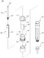
도 2는 도 1에 도시된 실시예의 개략적인 분해 사시도이다.
도 3은 도 1에 도시된 실시예의 구동유닛의 개략적인 분해 사시도이다.
도 4는 도 1에 도시된 실시예의 구동유닛을 도 3과는 다른 각도에서 본 개략적인 분해 사시도이다.
도 5는 도 1에 도시된 실시예의 기어박스의 개략적인 분해 사시도이다.
도 6은 도 3의 기어박스에서 제2 지지대와 제3 지지대를 제거하고 도시한 개략적인 사시도이다.
도 7은 도 2에 도시된 실시예의 피스톤푸싱유닛의 개략적인 분해 사시도이다.
도 8은 도 2의 피스톤푸싱유닛를 도 7과는 다른 각도에서 본 개략적인 분해 사시도이다.
도 9는 도 2에 도시된 실시예에서 자동/수동 전환수단의 슬라이드체의 개략적인 사시도이다.
도 10은 제2 케이스를 제거하고 구동유닛와 피스톤푸싱유닛이 연결되는 상태를 나타내는 설명도이다.
도 11은 수동으로 인슐린을 주입하는 방법을 나타내는 작동 설명도이다.
도 12는 본 발명에 따른 다른 실시예의 부분 단면 사시도이다.1 is a schematic perspective view of one embodiment of a pen-type insulin infusion device according to the present invention.
FIG. 2 is a schematic exploded perspective view of the embodiment shown in FIG. 1.
3 is a schematic exploded perspective view of the drive unit of the embodiment shown in FIG.
Figure 4 is a schematic exploded perspective view of the drive unit of the embodiment shown in Figure 1 seen from a different angle than FIG.
5 is a schematic exploded perspective view of the gearbox of the embodiment shown in FIG.
FIG. 6 is a schematic perspective view of the gear box of FIG. 3 with the second and third supports removed.
7 is a schematic exploded perspective view of the piston pushing unit of the embodiment shown in FIG.
8 is a schematic exploded perspective view of the piston pushing unit of FIG. 2 viewed from an angle different from that of FIG. 7.
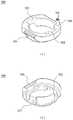
9 is a schematic perspective view of the slide body of the automatic / manual switching means in the embodiment shown in FIG.
10 is an explanatory view showing a state in which the second case is removed and the driving unit and the piston pushing unit are connected.
11 is an operation explanatory diagram showing a method of injecting insulin manually.
12 is a partial cross-sectional perspective view of another embodiment according to the present invention.
이하 첨부된 도면을 참조하여 본 발명의 바람직한 실시예에 대하여 상세히 설명한다.Hereinafter, exemplary embodiments of the present invention will be described in detail with reference to the accompanying drawings.
본 실시예에 대한 설명에서, '상측' 또는 '상부측'이라 함은 구동유닛(100)의 말단부(distal end)가 위치하는 방향을 의미하고, '하측' 또는 '하부측'이라 함은 피스톤푸싱유닛(200)의 말단부(distal end)가 위치하는 방향을 의미한다.In the description of the present embodiment, 'upper' or 'upper side' means a direction in which a distal end of the
도 1 및 도 2를 참조하면, 본 실시예의 펜형 인슐린 주입 장치는 구동유닛(100)과, 피스톤푸싱유닛(200)과, 자동/수동 전환수단을 포함한다. 구동유닛(100)은 밧데리를 내장하고 있으며 모타의 회전력을 기어박스를 통하여 피스톤푸싱유닛(200)에 전달하도록 피스톤푸싱유닛(200)과 결합되어 있다. 피스톤푸싱유닛(200)은 카트리지고정체(260)를 포함하고, 인슐린이 내장된 카트리지(1)는 카트리지고정체(260)에 착탈 가능하게 장착된다. 또한, 인슐린 주입장치를 사용하지 않을 경우 커버(201)를 피스톤푸싱유닛(200)에 끼워서 장치를 보호한다.1 and 2, the pen-type insulin injector of this embodiment includes a
도 2 및 도 3을 참조하면, 구동유닛(100)과 피스톤푸싱유닛(200)은 푸셔하우징(210)의 칼라(212)가 제1 케이스(111)와 제2 케이스(112)의 내주면에 형성된 칼라홈(127)에 끼워져서 연결되어 회전은 가능하나, 길이 방향으로는 이동할 수 없도록 구속되어 있다. 또한 슬라이드체(300)의 위치에 따라서, 구동유닛(100)은 피스톤푸싱유닛(200)에 대하여 회전하지 못하도록 구속되거나, 회전이 가능하도록 구속이 해제되도록 되어 있다. 이에 대한 자세한 설명은 후술한다.2 and 3, the driving
먼저, 구동유닛(100)에 대해 설명한다. 도 3 및 도 4를 참조하면, 구동유닛(100)은, 케이스와, 모터(130)와, 제어부(140)와, 표시부(150)와, 기어박스(160)를 포함한다.First, the driving
케이스는 분할된 제1 케이스(111)와 제2 케이스(112)와 제3 케이스(113)와 제4 케이스(114)가 조립되어 형성되도록 되어 있다. 조립된 케이스의 내부에는 모터(130)와 제어부(140)와 표시부(150)와 기어박스(160)가 장착 고정된다.The case is formed by assembling the divided
제1 케이스(111)에는 USB연결용 홀(115)이 형성되어 있다. USB연결용 홀(115)을 폐쇄하기 위한 USB연결용 홀 커버(116)가 착탈 가능하게 설치되어 있다. 제2 케이스(112)에는 조작 버튼용 홀(117)이 형성되어 있다. 본 실시예에서 조작 버튼(141)이 세 개이므로 세 개의 조작 버튼용 홀(117)이 형성되어 있다. 제1 케이스(111)와 제2 케이스(112)는 서로 하측 부분에서 결합되며, 결합 되었을 때 주입량 확인용 홀(118)이 형성된다. 또한 주입량 확인용 홀(118)에는 투명한 플라스틱이나 유리 재질의 주입량 확인용 홀 커버(119)가 끼워진다. A
제3 케이스(113)에는 표시부(150)를 외부에서 볼 수 있게 하는 표시부용 홀(120)이 구비된다. 또한, 제4 케이스(114)에는 작동 버튼(142)을 외부로 노출시키는 작동 버튼용 홀(121)이 상측에 구비된다. 제3 케이스(113)와 제4 케이스(114)는 제어부(140)와 표시부(150)를 내부에 두고 서로 결합되며, 결합 후에는 제1 케이스(111)와 제2 케이스(112) 사이에 끼워져서 고정된다. 한편, 제1 내지 제4 케이스가 모두 결합되면, 제1 케이스(111)와 제2 케이스(112)와 제3 케이스(113)에 의하여 반원 모양의 수동 조작용 홀(122)이 형성되도록 되어 있다. 이 수동 조작용 홀(122)에는 개폐 가능한 수동 조작용 홀 커버(123)가 장착된다.The
제어부(140)는 모터(130)의 회전을 제어하여, 모터(130)의 구동축은 기어박스(160)와 연결된다. 또한, 모터(130)와 제어부(140)에 전력을 공급하기 위한 배터리(144)는 제어부(140)의 측면에 설치된다. 제어부(140)는 사용자가 입력한 정보를 받아 이를 처리하여 모터(130)를 구동한다. 제어부(140)는 외부에 노출된 조작 버튼(141)으로부터 명령을 받으며, 이에 대한 정보는 표시부(150)에 표시된다. 또한, 제어부(140)에는 작동 버튼(142)이 연결되고, 정보를 외부로 전달하거나 외부로부터 전달받기 위한 USB 커넥터(143)가 연결된다. 표시부(150)는 인슐린 주입에 관한 정보 즉, 인슐린 주입량, 주입 시간 등에 관한 정보를 제어부(140)로부터 제공 받아 외부에 표시하는 부분으로서, LCD를 사용한다.The
도 5 내지 도 7을 참조하면, 기어박스(160)는 모터(130)의 회전력을 전달받아 정해진 감속비로 전동축(230)에 회전력을 전달한다. 기어박스(160)는 모터(130)의 구동축에 연결되는 제1 스퍼 기어(161)와, 제1 더블 스퍼 기어(164)와, 아이들 기어(165)와, 제2 더블 스퍼 기어(168)와, 제3 더블 스퍼 기어(171)와, 제2 스퍼 기어(172)를 포함한다. 제1 스퍼 기어(161)는 제1 더블 스퍼 기어(164)의 상측 기어(162)와 치가 맞물리고, 아이들 기어(165)는 제1 더블 스퍼 기어(164)의 하측 기어(163)와 치가 맞물려 진다. 또한, 아이들 기어(165)는 제2 더블 스퍼 기어(168)의 상측 기어(166)와 치가 맞물려 있고, 제2 더블 스퍼 기어(168)의 하측 기어(167)는 제3 더블 스퍼 기어(171)의 상측 기어(169)와 치가 맞물려 있다. 제2 스퍼 기어(172)는 제3 더블 스퍼 기어(171)의 하측 기어(170)와 치가 맞물려 있으며, 전동축(230)과 연결된다.5 to 7, the
모터(130)의 회전력은 제1 스퍼 기어(161), 제1 더블 스퍼 기어(164), 아이들 기어(165), 제2 더블 스퍼 기어(168), 제3 더블 스퍼 기어(171), 제2 스퍼 기어(172) 순으로 전달된다. 또한, 기어박스(160)의 감속비는, 제1 스퍼 기어(161)와 제1 더블 스퍼 기어(164)의 상측 기어(162)의 잇수비, 제1 더블 스퍼 기어(164)의 상측 기어(164)와 하측 기어(163)의 잇수비, 제2 더블 스퍼 기어(168)의 상측 기어(166)와 하측 기어(167)의 잇수비, 제3 더블 스퍼 기어(171)의 상측 기어(169)와 하측 기어(170)의 잇수비, 제3 더블 스퍼 기어(171)의 하측 기어(170)와 제2 스퍼 기어(172)의 잇수비로 정해진다. 아이들 기어(165)는 감속비에 영향을 미치지 않는다.Rotational force of the
아이들 기어(165)에는 원주방향을 따라서 일정한 간격으로 복수의 회전감지홀(176)이 형성되어 있다. 또한, 기어박스(160)에는 발광부(174)와 수광부(175)를 가지고, 발광부(174)에서 방출한 빛이 아이들 기어(165)의 회전감지홀(176)을 통과하여 수광부(175)에 방사되도록 광센서(173)가 설치되어 있다. 광센서(173)는 아이들 기어(165)의 회전에 대한 신호을 검출하여 제어부(140)로 전송한다.The
한편, 제3 더블 스퍼 기어(171)의 상측 기어(169)의 하측면에는 원주방향으로 복수의 구속홈이 형성되도록 복수의 돌기(176)가 일정한 간격으로 형성되어 있다. 일정한 간격으로 배열된 돌기(176)에 의하여 형성되는 구속홈에는 슬라이드체(300)의 구속돌기(301)가 끼워져서 기어의 회전을 구속한다. 구속돌기(301)의 단부면에는 상측기어(167)의 돌기(176)와 맞물려서 끼워지도록 나사산(303)이 형성되어 있다. 이들의 작용에 대한 자세한 설명은 후술한다.On the other hand, the lower surface of the
기어박스(160)의 기어들과 광센서는 제1 기어 지지부(177)와 제2 기어 지지부(178)와 제3 기어 지지부(179)에 의해서 위치가 정해진다. 제1 기어 지지부(177)에는 복수의 기어 지지축(180)이 형성되어 있고, 이러한 기어 지지축(180)의 말단은 제2 기어 지지부(178) 또는 제3 기어 지지부(179)에 끼워져서 고정된다. 또한, 제3 기어 지지부(179)의 하부 면에는 한 쌍의 슬라이드체 가이드(181)가 돌출 형성되어 있다. 또한, 제3 기어 지지부(179)에는 슬라이드체(300)의 구속돌기(301)가 통과되기 위한 구속돌기 통과홀(182)이 형성되어 있다.The gears and the optical sensor of the
다음으로, 피스톤푸싱유닛(200)에 대해서 상세히 설명한다. 피스톤푸싱유닛(200)는 구동유닛(100)으로부터 회전력을 전달받아, 푸셔(240)가 직선 운동하도록 하여 카트리지(10)의 피스톤을 가압하도록 변환시키는 기능을 한다.Next, the
도 7 및 도 8을 참조하면, 피스톤푸싱유닛(200)는 푸셔하우징(210)과, 전동축(230)과, 푸셔(240)를 포함한다. 또한, 푸셔하우징(210)에는 수동주입량표시체(250)가 끼워져 있고, 푸셔하우징(210)의 하측 단부에는 카트리지 접속체(220)가 고정되어 있다. 수동주입량 표시체(250)는 푸셔하우징(210)에 끼워져서 회전 가능하도록 설치되어 있다.7 and 8, the
푸셔하우징(210)은 길이 방향으로 관통구멍이 형성된 중공의 실린더 형상으로, 내주면에는 길이방향으로 돌출된 한 쌍의 슬라이드돌기(211)가 형성되어 있다. 슬라이드돌기(211)는 중공 내부에 삽입되는 푸셔가 회전 운동을 하지 않고 직선운동을 하도록 가이드하기 위한 것이다. 또한, 푸셔하우징(210)의 상부측 단부의 외주면에는 환상으로 돌출된 칼라(COLLAR)(212)가 형성되어 있다. 또한, 푸셔하우징(210)의 칼라(212)의 하부면에는 원주방향으로 복수의 돌기(214)가 등간격으로 형성되어 있다. 푸셔하우징(210)의 칼라(212)는 제1 케이스(111)와 제2 케이스(112)의 내주면에 형성된 칼라홈(127)에 삽입되어 푸셔하우징(210)과 구동유닛(100)을 연결한다. 칼라(212)는 칼라홈(127)에 삽입되어 푸셔하우징(210)과 구동유닛(100)을 길이방향으로는 분리되지 않고 회전이 가능하도록 결합한다. 푸셔하우징(210)의 외주면에는 수동주입량 표시체(250)와 슬라이드체(300)가 끼워져서 설치되는데, 이들의 구조와 작동에 대하여는 후술한다.The
전동축(230)의 상부측 단부(231)는 기어박스(160)의 제2스퍼어 기어(172)에 삽입되어 회전력을 전달받을 수 있도록 고정된다. 전동축(230)의 하부측 단부의 외주면에는 나사(232)가 형성되어 있다. 전동축(230)은 푸셔(240)의 중공에 삽입되고, 하부측 단부의 나사(232)는 푸셔(240)의 내주면에 형성된 나사와 맞물려 있다. 전동축(230)이 회전하면, 회전운동이 구속되도록 푸셔하우징(210)의 중공에 삽입된 푸셔(240)는 직선운동하도록 되어 있다.The
푸셔(240)는 중공의 실린더 형상으로 중공의 내주면에는 전동축의 나사(232)와 나사결합되기 위한 나사가 형성되어 있다. 또한, 푸셔(240)의 외주면에는 푸셔하우징(210)의 중공에 삽입되어 슬라이드돌기(211)를 수용하기 위한 한 쌍의 슬라이드홈(241)이 길이방향으로 형성되어 있다. 푸셔(240)는 푸셔하우징(210)의 중공에 삽입될 때 슬라이드돌기(211)과 슬라이드홈(241)이 맞물리도록 삽입되어, 회전운동은 구속되고 길이방향으로 슬라이딩 직선운동만이 가능하도록 구속된다. 따라서 전동축(230)을 회전시키면, 전동축(230)과 내주면에서 나사 결합된 푸셔(240)는 외주면에 형성된 슬라이드홈(241)에 삽입된 푸셔하우징(210)의 슬라이드돌기(211)에 의하여 회전이 방해되어 회전운동을 하지 못하고, 직선운동을 하게 된다.The
수동주입량 표시체(250)는 중공의 실린더 형상으로, 푸셔하우징(210)의 외주면에 회전 가능하도록 끼워져 있다. 주입량 표시체(250)의 외주면의 상부측에는 회전 각도에 따른 인슐린 주입량이 등간격으로 표시된 주입량 표시부(251)가 구비되고, 하부측에는 사용자가 회전시키기 편하게 하기 위한 손잡이부(252)가 형성되어 있다. 또한, 상부측 단부면에는 멈춤돌기(253)가 길이방향으로 돌출되도록 형성되어 있다. 주입량 표시체(250)의 하부에는 카트리지 접속체(220)가 푸셔하우징(210)에 끼워져서 고정된다.The manual
카트리지 고정체(260)는 카트리지 접속체(220)와 나사로 착탈이 가능하게 결합되고, 인슐린이 들어 있는 카트리지(1)를 수용한다. 카트리지 고정체(260)의 외주면에는 수용된 카트리지(1)의 인슐린의 잔량을 확인하기 위한 잔량 확인용 홀(261)이 형성되어 있다. 니들 접속체(270)는 카트리지 고정체(260)의 하부측에 고정되며, 나사로 착탈이 가능하게 결합된다. The
도 2, 도8 및 도 9를 참조하여, 인슐린 주입 모드를 자동과 수동으로 전환시키기 위한 자동/수동 전환수단에 대하여 설명한다.With reference to Figs. 2, 8 and 9, the automatic / manual switching means for automatically and manually switching the insulin infusion mode will be described.
자동/수동 전환수단은, 제1위치에서 케이스와 푸셔하우징(210)이 상대 회전 운동을 하지 못하도록 구속하고 동시에 모터의 회전력이 전동축(230)에 전달되도록 기어박스(160)의 복수의 기어 중 어느 하나의 기어의 구속을 해제한다. 또한, 자동/수동 전환수단은, 제2위치에서 케이스와 퓨셔하우징(210)이 상대 회전 운동을 할 수 있도록 구속을 해제하고 동시에 모터의 회전력이 전동축(230)에 전달되지 못하도록 기어박스의 복수의 기어중 어느 하나의 기어의 회전을 구속한다.The automatic / manual switching means, among the plurality of gears of the
상기와 같은 기능을 하는 자동/수동 전환수단은, 슬라이드체(300)와, 케이스와 푸셔하우징을 연결하거나 분리하기 위한 연결절환수단과, 슬라이드체의 슬라이딩에 연동되어 상기 기어박스의 기어의 회전을 구속하거나 구속을 해제하기 위한 기어구속수단을 포함한다.Automatic / manual switching means having the above function, the
슬라이드체(300)는 케이스에 대하여 길이방향으로 슬라이딩이 가능하게 구속되어 있다. 슬라이드체(300)는 일정한 길이를 갖는 링형상으로 푸셔하우징(210)의 칼라(212)의 상부측에 끼워져서 길이방향으로 슬라이딩이 가능하게 설치된다. 슬라이드체(300)의 내주면에는 길이 방향으로 한 쌍의 가이드홈(302)이 형성되어 있다. 또한, 푸셔하우징(210)의 칼라(212)의 케이스를 향하는 상부측 면에는 한쌍의 가이드돌기(213)가 상부측으로 돌출되도록 형성되어 있다.The
또한, 슬라이트체(300)의 케이스를 향하는 상부측 단부면에는 상부로 돌출된 구속돌기(301)가 형성되어 있다. 구속돌기(301)는 제3 더블 스퍼 기어(171)의 상측 기어(169)의 하측면에 일정한 간격으로 배열된 돌기(176)에 의하여 형성되는 구속홈에는 끼워져서 제3 더블 스퍼 기어(171)가 회전하지 못하도록 한다. 구속돌기(301)의 단부면에는 구속력을 크게하기 위하여 상측기어(167)의 돌기(176)와 맞물려서 끼워지도록 나사산(303)이 형성되어 있다.In addition, a constraining
슬라이드체(300)가 푸셔하우징(210) 방향으로 이동된 상태가 제1위치 상태이고, 케이스 방향으로 이동된 상태가 제2위치 상태이다. 연결절환수단은, 슬라이드체(300)가 제1위치에서 케이스와 푸셔하우징(210)이 상대적으로 회전하지 못하도록 케이스와 푸셔하우징(210)을 연결하고, 제2위치에서 푸셔하우징(210)이 케이스에 대하여 상대적으로 회전할 수 있도록 케이스와 푸셔하우징을 분리하는 기능을 한다.The state in which the
본 실시예에서, 연결절환수단은 슬라이드체(300)의 내주면에 형성된 한 쌍의 가이드홈(302)과 푸셔하우징(210)에 형성된 가이드돌기(213)로 구성이다. 가이드돌기(213)는 제2위치에서 가이드홈(302)으로부터 분리되도록 되어 있어서, 푸셔하우징(210)은 케이스에 대하여 회전이 가능하다.In this embodiment, the connection switching means is composed of a pair of
또한 본실시예에서, 기어구속수단은 슬라이드체(300)의 구속돌기(301)와 제3 더블 스퍼 기어(171)의 상측 기어(169)의 하측면에 일정한 간격으로 배열된 돌기(176)에 의하여 형성되는 구속홈으로 구성된다. 슬라이드체(300)를 상측으로 이동시킬 경우 구속돌기(301)는 제3 기어 지지부(179)에 형성된 잠금용 홀(182)을 관통하여 기어박스(160) 내부로 삽입된다. 구속돌기(301)는 제2위치에서 제3 더블 스퍼기어(171)의 구속홈에 삽입되어 제3 더블스퍼기어(171)가 회전하지 못하도록 구속한다.In addition, in this embodiment, the gear restraining means is provided on the
제1위치에서 푸셔하우징(210)의 한 쌍의 가이드돌기(213)는 슬라이드체(300)의 대응하는 한 쌍의 가이드홈(302)에 하부에서 삽입되어 슬라이드체(300)와 푸셔하우징(210)이 일체로 회전하도록 구속한다. 또한, 기어박스(160)의 제3 기어 지지부(179)의 하부 면에 형성된 한 쌍의 슬라이드체 가이드돌기(181)도 슬라이드체(300)의 대응하는 한 쌍의 가이드홈(302)에 상부에서 삽입되어 기어박스(160)와 슬라이드체(300)가 일체로 회전하도록 구속한다. 즉, 제1 상태에서 구동유닛(100)과 피스톤푸싱유닛(200)은 상대적으로 회전하지 못하도록 구속되어 있고, 모터의 회전가 회전하면, 푸셔(240)는 푸셔하우징(210)에 대하여 슬라이딩하게 된다.The pair of
제2위치에서는 푸셔하우징(210)의 한 쌍의 가이드돌기(213)가 슬라이드체(300)의 한 쌍의 가이드홈(302)으로부터 분리된다. 즉, 구동유닛(100)과 피스톤푸싱유닛(200)은 일체로 회전하도록 된 구속이 해제되어 상대적으로 회전이 가능한 상태가 된다. 동시에 슬라이드체(300)의 구속돌기(301)가 상승하여 제3 더블 스퍼기어(171)를 회전하지 못하도록 구속한다. 즉, 제2위치에서 피스톤푸싱유닛(200)에 대하여 구동유닛(100)을 회전시키면, 전동축(230)이 구동유닛(200)과 함께 회전하고, 푸셔(240)는 푸셔하우징(210)에 대하여 슬라이딩하게 된다.In the second position, the pair of
도 10은 제2 케이스를 제거하고 구동유닛(100)과 피스톤푸싱유닛(200)이 연결되는 부분을 나타내는 설명도이고, 도 11은 모터가 고장난 경우나 밧데리가 소모된 경우와 같은 비상 시에 인슐린주입장치를 수동으로 사용하는 방법을 설명하는 설명도이다. FIG. 10 is an explanatory view showing a part in which the second case is removed and the
도 10과 도 11를 참조하여, 본 실시예의 펜형 휴대용 인슐린 주입 장치의 평상 시 사용 방법과, 비상 시 사용 방법에 대해 설명한다.With reference to FIG. 10 and FIG. 11, the normal use method and the emergency use method of the pen type portable insulin injecting apparatus of this embodiment are demonstrated.
평상 시란 모터(130)가 정상적으로 동작하는 경우를 말한다. 평상 시에는 원하는 주입량을 조작 버튼(141)을 통해 입력하고 작동 버튼(142)을 누르면 제어부가 모터(130)의 회전을 제어하여 원하는 양만큼 인슐린을 주입할 수 있다. 평상시에는 슬라이드체(300)가 제1위치에 위치하여 구동유닛(100)와 피스톤푸싱유닛(200)는 상대적으로 회전할 수 없도록 구속되어 있다.Normally refers to a case in which the
평상 시에는 도 10(a)에 도시된 것과 같이, 슬라이드체(300)를 하부측으로 최대한 밀어서 푸셔하우징(210)의 고정돌기(213)가 슬라이드체(300)의 고정홈(302)에 끼워지도록 되어 있고, 동시에 구속돌기(301)는 기어박스(160)의 제3 더블 스퍼 기어(171)를 구속하지(잠그지) 않은 위치에 위치하도록 되어 있다. 이러한 상태를 '제1 위치' 상태라고 한다. 슬라이드체(300)가 제1 위치에 위치하면, 푸셔하우징(210)이 슬라이드체(300)를 매개로 구동유닛(100)과 연결되어 상대적으로 회전하지 못하게 된다. 이는 가이드홈(302)에 가이드돌기(213)와 슬라이드체 가이드돌기(181)가 동시에 삽입되어 있기 때문이다. 또한, 기어박스(160)의 기어가 회전이 가능한 상태에 있기 때문에 모터(120)의 동력이 기어박스(160)를 통해 전동축(230)으로 전달될 수 있다. 또한, 수동 조작용 홀 커버(123)의 내측에는 슬라이드체(300)가 상측으로 이동할 수 없도록 제한하는 제한턱(124)이 형성되어 있어서, 수동 조작용 홀 커버(123)를 닫았을 경우, 제한턱(124)에 걸려서 슬라이드체(300)를 제1 위치에 고정할 수 있다.Normally, as shown in FIG. 10 (a), the
비상 시란 밧데리가 소모되거나, 제어부(140)가 고장이 나거나 한 경우와 같이 모터(130)가 작동하지 않는 경우를 말한다. 비상 시에는 구동유닛(100)를 수동으로 회전시켜서 인슐린을 주입할 수 있다.The emergency refers to a case in which the
비상 시에는 도 10(b)에 도시된 것과 같이, 슬라이드체(300)를 상부측으로 최대한 밀어서 가이드돌기(213)가 가이드홈(302)에서 이탈되도록 하고, 동시에 구속돌기(301)는 기어박스(160)의 내측으로 삽입되도록 하여, 구속돌기(301)의 단부면에 형성된 나사(303)가 제3 더블 스퍼 기어(171)에 형성된 돌기(176)와 맞물리도록 한다. 이러한 상태를 '제2 위치' 상태라 한다. 슬라이드체(300)가 제2 위치에 위치하면, 구동유닛(100)이 피스톤푸싱유닛(200)에 대하여 상대적으로 회전이 가능하고, 기어박스(160)의 기어는 회전할 수 없게 된다. 제2 위치 상태에서, 구동유닛(100)을 회전시키면 기어박스(160)가 잠겨 있는(구속된) 상태이므로, 구동유닛(100)과 함께 전동축(230)이 회전하고, 이에 따라서 푸셔(240)가 푸셔하우징(210)의 내부에서 슬라이딩하게 된다. 또한, 수동 조작용 홀 커버(123)를 닫았을 경우, 슬라이드체(300)는 제한턱(124)에 걸려서 제2 위치에서 고정된다.In an emergency, as shown in FIG. 10 (b), the
한편, 제3 기어 지지부(179)의 하측면에 형성된 슬라이드체 가이드돌기(181)는 가이드홈(302)에 항상 삽입되어 있으므로, 슬라이드체(300)를 제1 위치에서 제2 위치로 이동시킬 때 슬라이드체(300)는 회전하지 않고 슬라이드체 가이드돌기(181)를 따라서 이동될 수 있도록 안내된다. 또한, 제1 위치나 제2 위치에서 슬라이드체 가이드돌기(181)가 가이드홈(302)에 삽입되어 있어서, 슬라이드체(300)는 항상 구동유닛(100)에 대해서 회전운동을 하지 않고 길이 방향으로만 이동한다.On the other hand, since the slide
도 11을 참조하여, 비상 시 본 실시예의 펜형 휴대용 인슐린 주입 장치의 사용 방법을 자세히 설명하면 다음과 같다.Referring to Figure 11, when described in detail the use of the pen-type portable insulin infusion device of the present embodiment in an emergency as follows.
먼저, 도 11의 (a)에 도시된 것과 같이, 수동 조작용 홀 커버(123)를 연다. 그 다음에, 도 11의 (b)에 도시된 것과 같이, 슬라이드체(300)를 상부측으로 밀어 올려서 제2 위치에 위치시킨 후, 수동 조작용 홀 커버(123)을 닫아 슬라이드체(300)가 다시 제1 위치로 돌아가지 못하도록 고정한다. 다음으로, 도 11의 (c)에 도시된 것과 같이, 수동주입량 표시체(250)를 시계방향으로 돌려서 주입량 확인용 홀(118)에 원하는 주입량이 표시되도록 한다. 이때, 수동주입량 표시체(250)의 멈춤돌기(253)가 푸셔하우징(210)의 돌기(214)와 탄성적으로 접촉하여 회전하도록 되어 있어서 정해진 각도의 간격 만큼씩 회전하도록 되어 있어서 원하는 주입량을 정하기에 편리하다.First, as shown in Fig. 11A, the
인슐린 주입을 위하여 주사 바늘을 피부에 삽입한 후, 도 11의 (d)에 도시된 것과 같이, 주입량 확인용 홀(118)에 나타난 수치가 0이 될 때까지 구동유닛(100)를 회전시켜서 정해진 양만큼 인슐린을 주입한다. 도 3을 참조하면, 수동으로 인슐린을 주입할 경우 제1 케이스(111)의 내주면에 형성된 탄성돌기(125)가 푸셔하우징(210)의 칼라(212)의 하부측 면에 형성된 돌기(214)와 탄성접촉을 하면서 회전하도록 되어 있어서, 구동유닛(100)을 회전 시킬때 정해진 각도의 간격 만큼씩 회전시킬 수 있다. 또한, 주입량 확인용 홀(118)에 나타난 수치가 0이 될 때, 멈춤돌기(253)에 제1 케이스(111)의 내측면에 형성된 회전제한용 돌기(126)가 걸려서 더 이상 회전을 시킬 수 없도록 구속하여 정한 양만큼만 정확하게 주입할 수 있도록 한다.After inserting the injection needle into the skin for insulin injection, as shown in (d) of FIG. 11, the driving
도 12에 도시된 실시예가 도 1에 도시된 실시예와 다른 점은 제1 케이스(111)에 형성된 탄성돌기(125) 대신에 제3 기어 지지부(179)에 탄성돌기(125-1_를 형성하고 푸셔하우징(120)의 상부측 단부면에 요철(214-1)을 형성하여, 수동 주입을 위하여 구동유닛을 회전시킬 때 탄성돌기(125-1)가 요철(214-1)과 탄성접촉하도록 하여 정해진 각도 만큼씩 회전시킬 수 있도록 한 점이다.The embodiment illustrated in FIG. 12 is different from the embodiment illustrated in FIG. 1, instead of the
도면들을 참조하여 본 발명을 바람직한 일실시예에 대하여 상세하게 설명하였으나, 본 발명은 앞에서 설명한 실시예에 한정되지 않으며, 본 발명의 보호범위는 청구범위에 기재된 사항에 의하여 정하여 진다.Although the present invention has been described in detail with reference to the drawings, a preferred embodiment, the invention is not limited to the embodiment described above, the scope of the invention is defined by the matters set forth in the claims.
1...카트리지100...구동유닛
111...제1 케이스112...제2 케이스
113...제3 케이스114...제4 케이스
130...모터140...제어부
150...표시부160...기어박스
165...아이들 기어200...피스톤푸싱유닛
210...푸셔하우징220...카트리지 접속부
230...전동축240...푸셔
250...수동주입량 표시체260...카트리지 고정체
270...니들 접속체300...슬라이드체1.
111 ...
113 ...
130 ...
150 ... Display 160 ... Gearbox
165
210 ...
230 ...
250 ... Manual
270 ...
Claims (8)
Translated fromKorean케이스와, 상기 케이스 내부에 고정 설치된 모터와, 상기 케이스 내부에 고정 설치되고 상기 모터의 구동축에 연결되어 모터의 회전력을 전달하기 위하여 맞물린 복수의 기어가 설치된 기어박스를 포함하는 구동유닛과;
길이방향으로 관통구멍이 형성되어 있고 관통구멍이 형성된 일단이 상기 케이스에 회전가능하게 연결된 푸셔하우징과, 상기 기어박스로 부터 회전력을 전달받도록 일단이 기어박스에 연결되고 상기 푸셔하우징의 관통구멍에 삽입된 전동축과, 상기 푸셔하우징의 관통구멍 내부에 설치되고 상기 전동축의 회전력을 전달받아 푸셔하우징의 관통구멍 내부에서 길이방향으로 슬라이딩하도록 구속된 푸셔를 포함하는 피스톤푸싱유닛과;
제1위치에서 상기 케이스와 푸셔하우징이 상대 회전 운동을 하지 못하도록 구속하고 동시에 모터의 회전력이 전동축에 전달되도록 기어박스의 복수의 기어 중 어느 하나의 기어의 구속을 해제하고, 제2위치에서 상기 케이스와 퓨셔하우징이 상대 회전 운동을 할 수 있도록 구속을 해제하고 동시에 모터의 회전력이 전동축에 전달되지 못하도록 기어박스의 복수의 기어중 어느 하나의 기어의 회전을 구속하는 자동/수동 전환수단을;
포함하는 것을 특징으로 하는 펜형 휴대용 인슐린 주입 장치.A pen-type portable insulin infusion device for injecting insulin into a human body by mounting a cartridge containing insulin,
A drive unit including a case, a motor fixedly installed in the case, and a gearbox fixedly installed in the case and connected to a drive shaft of the motor, the gearbox having a plurality of gears engaged to transmit rotational force of the motor;
A through hole is formed in the longitudinal direction and one end of the through hole is rotatably connected to the case, and one end is connected to the gear box so as to receive rotational force from the gear box and inserted into the through hole of the pusher housing. A piston pushing unit including a mounted shaft and a pusher installed inside the through hole of the pusher housing and being pushed to receive a rotational force of the driving shaft to slide longitudinally within the through hole of the pusher housing;
At the first position, the case and the pusher housing are restrained from the relative rotational movement and at the same time, the restraint of any one of the plurality of gears of the gearbox is transmitted so that the rotational force of the motor is transmitted to the electric shaft, and at the second position Automatic / manual switching means for releasing the restraint so that the case and the fuser housing can perform relative rotational movement and at the same time restrain the rotation of any one of the plurality of gears of the gearbox such that the rotational force of the motor is not transmitted to the electric shaft;
Pen-type portable insulin injection device comprising a.
상기 자동/수동 전환수단은,
상기 케이스에 대하여 길이방향으로 슬라이딩이 가능하게 구속된 슬라이드체와,
상기 슬라이드체가 푸셔하우징 방향으로 이동된 제1위치에서 상기 케이스와 푸셔하우징이 상대적으로 회전하지 못하도록 케이스와 푸셔하우징을 연결하고, 케이스 방향으로 이동된 제2위치에서 상기 푸셔하우징이 케이스에 대하여 상대적으로 회전할 수 있도록 케이스와 푸셔하우징을 분리하기 위한 연결절환수단과,
상기 슬라이드체의 슬라이딩에 연동되어 상기 기어박스의 기어의 회전을 구속하거나 구속을 해제하기 위한 기어구속수단을 포함하는 것을 특징으로 하는 펜형 휴대용 인슐린 주입 장치.The method of claim 1,
The automatic / manual switching means,
A slide body constrained to slide in the longitudinal direction with respect to the case;
The case and the pusher housing are connected to each other so that the case and the pusher housing are not rotated at the first position where the slide body is moved in the pusher housing direction, and the pusher housing is relatively to the case at the second position moved in the case direction. Connection switching means for separating the case and the pusher housing to rotate;
Pen-type portable insulin infusion device, characterized in that it comprises a gear restraining means for restraining or releasing the rotation of the gear of the gear box in conjunction with the sliding of the slide body.
상기 슬라이드체는, 일정한 길이를 갖는 링형상으로 푸셔하우징에 끼워져서 슬라이딩 가능하게 설치되어 있고,
상기 연결절환수단은, 상기 슬라이드체의 내주면 및 상기 푸셔하우징의 외주면 중 어느 하나에 길이방향으로 형성된 가이드홈과 나머지 하나에 길이방향으로 형성되어 상기 가이드홈에 끼워진 가이드돌기를 포함하고, 상기 제2위치에서 상기 가이드돌기는 가이드홈에서 분리되도록 되어 있으며,
상기 기어구속수단은, 상기 제2위치에서 기어박스의 복수의 기어중 어느 하나의 회전을 구속하도록 상기 슬라이드체의 케이스를 향하는 단부면에 돌출된 구속돌기와 상기 기어박스의 복수의 기어 중 어느 하나의 기어의 푸셔하우징을 향하는 면에 상기 구속돌기가 끼워지도록 형성된 구속홈을 포함하는 것을 특징으로 하는 펜형 휴대용 인슐린 주입 장치.The method of claim 2,
The slide body is provided in a ring shape having a constant length so as to slide in the pusher housing.
The connecting switching means may include a guide groove formed in one of a longitudinal direction on one of an inner circumferential surface of the slide body and an outer circumferential surface of the pusher housing and a guide protrusion formed in the lengthwise direction of the slide groove and fitted into the guide groove. The guide protrusion in position is to be separated from the guide groove,
The gear restraining means may include one of a plurality of gears of the gearbox and the restraining protrusion protruding from an end surface facing the case of the slide body to restrain rotation of any one of the plurality of gears of the gearbox at the second position. Pen-type portable insulin infusion device, characterized in that it comprises a restraint groove formed to fit the restraining projection on the surface facing the pusher housing of the gear.
상기 피스톤푸싱유닛은,
중공의 링형상으로, 중공에 푸셔하우징이 삽입되어 회전가능하게 설치되어 있으며, 외주면에 인슐린 주입량 표시 눈금이 표시된 수동주입량 표시체와,
슬라이더체가 제2위치에 위치할 때, 케이스의 회전각도를 상기 수동주입량 표시체의 회전각도로 제한하기 위한 수동주입량 제한수단을 더 포함하는 것을 특징으로 하는 펜형 휴대용 인슐린 주입 장치.4. The method according to any one of claims 1 to 3,
The piston pushing unit,
It is a hollow ring shape, the pusher housing is inserted into the hollow and rotatably installed, and the manual injection amount indicator with the insulin injection mark on the outer circumferential surface;
And a manual injection amount limiting means for limiting the rotation angle of the case to the rotation angle of the manual injection amount indicator when the slider body is located at the second position.
상기 수동주입량 제한 수단은, 상기 수동주입량표시체의 단부면에 돌출된 멈출돌기와, 상기 케이스의 내주면에 상기 멈춤돌기와 간섭되도록 형성된 걸림턱을 포함하는 것을 특징으로 하는 펜형 휴대용 인슐린 주입 장치.The method of claim 4, wherein
The manual injection amount limiting means, the pen-type portable insulin injecting device comprising a stop projection protruding on the end surface of the manual injection amount indicator body, and a locking step formed to interfere with the stop projection on the inner peripheral surface of the case.
상기 푸셔하우징의 일단부의 외주면에는 환상으로 돌출된 칼라가 형성되어 있으며,
상기 케이스의 내부면에는 상기 칼라를 수용하여 푸셔하우징을 회전가능하게 연결하기 위한 칼라홈이 형성되어 있고,
상기 전동축의 타단부에는 나사산이 형성되어 있고,
상기 푸셔는 중공의 원통형상으로 푸셔하우징의 관통구멍에 삽입되어 설치되어 있고, 내주면에는 상기 전동축의 타단에 형성된 나사산과 나사결합되기 위한 나사산이 형성되어 있고,
상기 푸셔하우징의 내주면과 상기 푸셔의 외주면 중 어느 하나에는 푸셔의 회전을 구속하기 위한 돌출부가 길이방향으로 길게 형성되어 있고, 나머지 하나에는 상기 돌출부가 삽입되도록 길이방향으로 길게 오목부가 형성된 것을 특징으로 하는 펜형 휴대용 인슐린 주입 장치.4. The method according to any one of claims 1 to 3,
The outer circumferential surface of one end of the pusher housing is formed with a collar protruding annularly,
The inner surface of the case is formed with a collar groove for receiving the collar to rotatably connect the pusher housing,
The other end of the transmission shaft is formed with a thread,
The pusher is a hollow cylindrical shape is inserted into the through-hole of the pusher housing, the inner circumferential surface is formed with a screw thread for screwing the screw thread formed on the other end of the transmission shaft,
One of the inner circumferential surface of the pusher housing and the outer circumferential surface of the pusher is formed with a protruding portion for restricting the rotation of the pusher in the longitudinal direction, and the other one has a concave portion formed in the longitudinal direction so that the protruding portion is inserted. Pen type portable insulin infusion device.
케이스와, 상기 케이스 내부에 고정 설치된 모터와, 상기 케이스 내부에 고정 설치되고 상기 모터의 구동축에 연결되어 모터의 회전력을 전달하기 위하여 맞물린 복수의 기어가 설치된 기어박스를 포함하는 구동유닛과;
길이방향으로 관통구멍이 형성되어 있고 관통구멍이 형성된 일단이 상기 케이스에 회전가능하게 고정된 푸셔하우징과, 상기 기어박스로 부터 회전력을 전달받도록 일단이 기어박스에 연결되고 상기 푸셔하우징의 관통구멍에 삽입된 전동축과, 상기 푸셔하우징의 관통구멍 내부에 설치되고 상기 전동축의 회전력을 전달받아 푸셔하우징의 관통구멍 내부에서 길이방향으로 슬라이딩하도록 구속된 푸셔를 포함하는 피스톤푸싱유닛을; 포함하고,
상기 기어박스는
원주방향으로 일정한 간격으로 배열된 다수의 회전감지홀이 형성된 아이들 기어와, 발광부와 수광부를 가지고, 상기 발광부에서 방출한 빛이 상기 아이들 기어의 센서홀을 통과하여 수광부에 조사되도록 설치된 광센서; 를
포함하는 것을 특징으로 하는 펜형 휴대용 인슐린 주입 장치.A pen-type portable insulin infusion device for injecting insulin into a human body by mounting a cartridge containing insulin,
A drive unit including a case, a motor fixedly installed in the case, and a gearbox fixedly installed in the case and connected to a drive shaft of the motor, the gearbox having a plurality of gears engaged to transmit rotational force of the motor;
A through hole is formed in the longitudinal direction and one end of the through hole is rotatably fixed to the case, and one end is connected to the gear box to receive rotational force from the gear box, and the through hole of the pusher housing. A piston pushing unit including an inserted electric shaft and a pusher installed inside the through hole of the pusher housing and being constrained to slide longitudinally within the through hole of the pusher housing by receiving the rotational force of the electric shaft; Including,
The gearbox
An optical sensor having an idle gear having a plurality of rotation sensing holes arranged at regular intervals in the circumferential direction, a light emitting unit and a light receiving unit, and installed so that the light emitted from the light emitting unit passes through the sensor hole of the idle gear and is irradiated to the light receiving unit. ; To
Pen-type portable insulin injection device comprising a.
상기 푸셔하우징의 일단부의 외주면에는 환상으로 돌출된 칼라가 형성되어 있으며,
상기 케이스의 내부면에는 상기 칼라를 수용하여 푸셔하우징을 회전가능하게 연결하기 위한 칼라홈이 형성되어 있고,
상기 전동축의 타단부에는 나사산이 형성되어 있고,
상기 푸셔는 중공의 원통형상으로 푸셔하우징의 관통구멍에 삽입되어 설치되어 있고, 내주면에는 상기 전동축의 타단에 형성된 나사산과 나사결합되기 위한 나사산이 형성되어 있고,
상기 푸셔하우징의 내주면과 상기 푸셔의 외주면 중 어느 하나에는 푸셔의 회전을 구속하기 위한 돌출부가 길이방향으로 길게 형성되어 있고, 나머지 하나에는 상기 돌출부가 삽입되도록 길이방향으로 길게 오목부가 형성된 것을 특징으로 하는 펜형 휴대용 인슐린 주입 장치.The method of claim 7, wherein
The outer circumferential surface of one end of the pusher housing is formed with a collar protruding annularly,
The inner surface of the case is formed with a collar groove for receiving the collar to rotatably connect the pusher housing,
The other end of the transmission shaft is formed with a thread,
The pusher is a hollow cylindrical shape is inserted into the through-hole of the pusher housing, the inner circumferential surface is formed with a screw thread for screwing the screw thread formed on the other end of the transmission shaft,
One of the inner circumferential surface of the pusher housing and the outer circumferential surface of the pusher is formed with a protruding portion for restricting the rotation of the pusher in the longitudinal direction, and the other one has a concave portion formed in the longitudinal direction so that the protruding portion is inserted. Pen type portable insulin infusion device.
Applications Claiming Priority (2)
| Application Number | Priority Date | Filing Date | Title |
|---|---|---|---|
| KR1020100041625 | 2010-05-04 | ||
| KR20100041625 | 2010-05-04 |
Publications (2)
| Publication Number | Publication Date |
|---|---|
| KR20110122647Atrue KR20110122647A (en) | 2011-11-10 |
| KR101217147B1 KR101217147B1 (en) | 2012-12-31 |
Family
ID=44904240
Family Applications (1)
| Application Number | Title | Priority Date | Filing Date |
|---|---|---|---|
| KR1020110042705AExpired - Fee RelatedKR101217147B1 (en) | 2010-05-04 | 2011-05-04 | Pen type portable insulin injection device |
Country Status (2)
| Country | Link |
|---|---|
| KR (1) | KR101217147B1 (en) |
| WO (1) | WO2011139110A2 (en) |
Cited By (3)
| Publication number | Priority date | Publication date | Assignee | Title |
|---|---|---|---|---|
| KR101396224B1 (en)* | 2012-08-30 | 2014-05-19 | 주식회사 에스에프에이 | Film separating apparatus for flat panel display |
| KR101404847B1 (en)* | 2012-05-04 | 2014-06-11 | 김종훈 | Pen type device for injecting medical fluid |
| WO2018056605A3 (en)* | 2016-09-23 | 2018-08-09 | 최규동 | Insulin injector capable of measuring oxygen saturation level and heart rate |
Families Citing this family (16)
| Publication number | Priority date | Publication date | Assignee | Title |
|---|---|---|---|---|
| KR101462438B1 (en)* | 2013-11-07 | 2014-11-17 | 주식회사 메가젠임플란트 | Apparatus for injecting medicine |
| KR101958067B1 (en)* | 2016-12-27 | 2019-07-04 | 최규동 | Monotoring and Magement System for Pen Type Injection Appartus |
| CN119950880A (en) | 2017-05-05 | 2025-05-09 | 里珍纳龙药品有限公司 | Auto-injectors and related methods of use |
| KR20200032310A (en) | 2018-09-18 | 2020-03-26 | 최규동 | Clutch Structure for Portable Injection Apparatus |
| KR20200032308A (en) | 2018-09-18 | 2020-03-26 | 최규동 | Catridge support Guide Structure for Portable Injection Apparatus |
| FR3086177B1 (en)* | 2018-09-20 | 2022-11-04 | Aptar France Sas | AUTOINJECTOR. |
| KR101992165B1 (en) | 2018-11-23 | 2019-09-30 | 이대로 | Automatic insulin infusion device |
| KR102081054B1 (en) | 2019-06-19 | 2020-02-25 | 이대로 | Automatic insulin infusion device |
| CN110772688A (en)* | 2019-12-02 | 2020-02-11 | 甘肃成纪生物药业有限公司 | Electronic injection pen and pushing device thereof |
| US11850402B2 (en)* | 2020-07-09 | 2023-12-26 | Eli Lilly And Company | Automatic injection device with reusable portion |
| KR102204634B1 (en) | 2020-09-23 | 2021-01-19 | 이대로 | Insulin Infusion Device |
| CN112755332B (en)* | 2020-12-29 | 2022-06-03 | 查维祎 | Fluid infusion system |
| CN113730729B (en)* | 2021-09-13 | 2023-08-18 | 郑州瑞宇科技有限公司 | Manual and electric integrated insulin injection pen and injection method thereof |
| KR102672546B1 (en) | 2021-09-22 | 2024-06-04 | 안영환 | Cover type Temperature Maintenance System for Pen Type Injection Appartus |
| KR20230088618A (en) | 2021-12-10 | 2023-06-20 | 이대로 | Insulin Infusion Device |
| EP4472702A1 (en)* | 2022-02-03 | 2024-12-11 | Eli Lilly and Company | Therapeutic agent delivery device with single motor drive |
Family Cites Families (4)
| Publication number | Priority date | Publication date | Assignee | Title |
|---|---|---|---|---|
| KR100478771B1 (en)* | 2003-03-27 | 2005-03-25 | 주식회사 엔터기술 | insulin pump |
| US8057436B2 (en)* | 2005-09-26 | 2011-11-15 | Asante Solutions, Inc. | Dispensing fluid from an infusion pump system |
| KR101366427B1 (en)* | 2009-03-13 | 2014-02-24 | 일라이 릴리 앤드 캄파니 | Apparatus for injecting a pharmaceutical with automatic syringe retraction following injection |
| KR100977283B1 (en)* | 2009-11-30 | 2010-08-24 | 장택희 | Syringe |
- 2011
- 2011-05-04WOPCT/KR2011/003368patent/WO2011139110A2/enactiveApplication Filing
- 2011-05-04KRKR1020110042705Apatent/KR101217147B1/ennot_activeExpired - Fee Related
Cited By (3)
| Publication number | Priority date | Publication date | Assignee | Title |
|---|---|---|---|---|
| KR101404847B1 (en)* | 2012-05-04 | 2014-06-11 | 김종훈 | Pen type device for injecting medical fluid |
| KR101396224B1 (en)* | 2012-08-30 | 2014-05-19 | 주식회사 에스에프에이 | Film separating apparatus for flat panel display |
| WO2018056605A3 (en)* | 2016-09-23 | 2018-08-09 | 최규동 | Insulin injector capable of measuring oxygen saturation level and heart rate |
Also Published As
| Publication number | Publication date |
|---|---|
| WO2011139110A2 (en) | 2011-11-10 |
| WO2011139110A3 (en) | 2012-04-26 |
| KR101217147B1 (en) | 2012-12-31 |
Similar Documents
| Publication | Publication Date | Title |
|---|---|---|
| KR101217147B1 (en) | Pen type portable insulin injection device | |
| RU2654614C2 (en) | Drug infusion device with safety interlock | |
| CA2808738C (en) | Portable medicine injection device and metering system | |
| KR20140035746A (en) | Pen type portable insulin injection device | |
| EP1095668B1 (en) | Electronic medication delivery pen having a multifunction actuator | |
| CN100569307C (en) | Hand-held electric-controlled injection device for injecting liquid medicine | |
| CN111432864B (en) | Medical delivery device with axially expandable drive band | |
| EP1583571B1 (en) | Medical dispensing device for insulin | |
| EP1732627A1 (en) | Injection apparatus having a needle cassette for delivering a pharmaceutical liquid | |
| JP2010104797A (en) | Drive mechanism for injection device, and injection device | |
| US20240033446A1 (en) | Fluid delivery system with needle assembly | |
| EP3909624A1 (en) | Drug delivery assembly for cartridge-based medicaments | |
| WO2014111336A1 (en) | Pen-type drug injection device and electronic add-on monitoring module for monitoring and logging dose setting and administration | |
| EP4262930A1 (en) | Fluid delivery system with needle assembly | |
| US20250262373A1 (en) | Drug delivery device cassette | |
| CN111194229B (en) | data collection device | |
| KR20200032308A (en) | Catridge support Guide Structure for Portable Injection Apparatus | |
| HK1223579B (en) | Drug infusion device with safety interlock |
Legal Events
| Date | Code | Title | Description |
|---|---|---|---|
| A201 | Request for examination | ||
| PA0109 | Patent application | St.27 status event code:A-0-1-A10-A12-nap-PA0109 | |
| PA0201 | Request for examination | St.27 status event code:A-1-2-D10-D11-exm-PA0201 | |
| R18-X000 | Changes to party contact information recorded | St.27 status event code:A-3-3-R10-R18-oth-X000 | |
| PG1501 | Laying open of application | St.27 status event code:A-1-1-Q10-Q12-nap-PG1501 | |
| R18-X000 | Changes to party contact information recorded | St.27 status event code:A-3-3-R10-R18-oth-X000 | |
| E701 | Decision to grant or registration of patent right | ||
| PE0701 | Decision of registration | St.27 status event code:A-1-2-D10-D22-exm-PE0701 | |
| GRNT | Written decision to grant | ||
| PR0701 | Registration of establishment | St.27 status event code:A-2-4-F10-F11-exm-PR0701 | |
| PR1002 | Payment of registration fee | St.27 status event code:A-2-2-U10-U11-oth-PR1002 Fee payment year number:1 | |
| PG1601 | Publication of registration | St.27 status event code:A-4-4-Q10-Q13-nap-PG1601 | |
| PN2301 | Change of applicant | St.27 status event code:A-5-5-R10-R13-asn-PN2301 St.27 status event code:A-5-5-R10-R11-asn-PN2301 | |
| S20-X000 | Security interest recorded | St.27 status event code:A-4-4-S10-S20-lic-X000 | |
| R18-X000 | Changes to party contact information recorded | St.27 status event code:A-5-5-R10-R18-oth-X000 | |
| PN2301 | Change of applicant | St.27 status event code:A-5-5-R10-R11-asn-PN2301 | |
| PN2301 | Change of applicant | St.27 status event code:A-5-5-R10-R14-asn-PN2301 | |
| R18-X000 | Changes to party contact information recorded | St.27 status event code:A-5-5-R10-R18-oth-X000 | |
| P14-X000 | Amendment of ip right document requested | St.27 status event code:A-5-5-P10-P14-nap-X000 | |
| FPAY | Annual fee payment | Payment date:20151224 Year of fee payment:4 | |
| PR1001 | Payment of annual fee | St.27 status event code:A-4-4-U10-U11-oth-PR1001 Fee payment year number:4 | |
| R18-X000 | Changes to party contact information recorded | St.27 status event code:A-5-5-R10-R18-oth-X000 | |
| PN2301 | Change of applicant | St.27 status event code:A-5-5-R10-R13-asn-PN2301 St.27 status event code:A-5-5-R10-R11-asn-PN2301 | |
| FPAY | Annual fee payment | Payment date:20161222 Year of fee payment:5 | |
| PR1001 | Payment of annual fee | St.27 status event code:A-4-4-U10-U11-oth-PR1001 Fee payment year number:5 | |
| FPAY | Annual fee payment | Payment date:20171219 Year of fee payment:6 | |
| PR1001 | Payment of annual fee | St.27 status event code:A-4-4-U10-U11-oth-PR1001 Fee payment year number:6 | |
| FPAY | Annual fee payment | Payment date:20181220 Year of fee payment:7 | |
| PR1001 | Payment of annual fee | St.27 status event code:A-4-4-U10-U11-oth-PR1001 Fee payment year number:7 | |
| PC1903 | Unpaid annual fee | St.27 status event code:A-4-4-U10-U13-oth-PC1903 Not in force date:20191225 Payment event data comment text:Termination Category : DEFAULT_OF_REGISTRATION_FEE | |
| PC1903 | Unpaid annual fee | St.27 status event code:N-4-6-H10-H13-oth-PC1903 Ip right cessation event data comment text:Termination Category : DEFAULT_OF_REGISTRATION_FEE Not in force date:20191225 |