KR20110122117A - Access device - Google Patents
Access deviceDownload PDFInfo
- Publication number
- KR20110122117A KR20110122117AKR1020117018850AKR20117018850AKR20110122117AKR 20110122117 AKR20110122117 AKR 20110122117AKR 1020117018850 AKR1020117018850 AKR 1020117018850AKR 20117018850 AKR20117018850 AKR 20117018850AKR 20110122117 AKR20110122117 AKR 20110122117A
- Authority
- KR
- South Korea
- Prior art keywords
- needle
- dilator
- hub
- sheath
- access
- Prior art date
- Legal status (The legal status is an assumption and is not a legal conclusion. Google has not performed a legal analysis and makes no representation as to the accuracy of the status listed.)
- Withdrawn
Links
- 230000003287optical effectEffects0.000claimsabstractdescription12
- 238000002059diagnostic imagingMethods0.000claimsabstractdescription4
- 229940127554medical productDrugs0.000claimsdescription40
- 238000000034methodMethods0.000claimsdescription34
- 230000007246mechanismEffects0.000claimsdescription27
- 239000000463materialSubstances0.000claimsdescription17
- 238000004806packaging method and processMethods0.000claimsdescription13
- 238000002604ultrasonographyMethods0.000claimsdescription5
- 238000013459approachMethods0.000claimsdescription4
- 238000012800visualizationMethods0.000claimsdescription3
- 238000002594fluoroscopyMethods0.000claimsdescription2
- 230000000149penetrating effectEffects0.000claims1
- 239000012530fluidSubstances0.000abstractdescription37
- 210000004369bloodAnatomy0.000abstractdescription36
- 239000008280bloodSubstances0.000abstractdescription36
- 238000003384imaging methodMethods0.000abstractdescription10
- 238000001514detection methodMethods0.000abstractdescription2
- 210000004204blood vesselAnatomy0.000description21
- 210000001124body fluidAnatomy0.000description10
- 239000010839body fluidSubstances0.000description10
- 238000003780insertionMethods0.000description8
- 230000037431insertionEffects0.000description8
- 230000002792vascularEffects0.000description7
- 239000012780transparent materialSubstances0.000description6
- 210000003462veinAnatomy0.000description6
- 230000017531blood circulationEffects0.000description5
- 210000003811fingerAnatomy0.000description5
- 239000007788liquidSubstances0.000description5
- 238000005520cutting processMethods0.000description4
- 238000004519manufacturing processMethods0.000description4
- 239000011148porous materialSubstances0.000description4
- 230000008569processEffects0.000description4
- 239000004094surface-active agentSubstances0.000description4
- 206010000269abscessDiseases0.000description3
- 229920001577copolymerPolymers0.000description3
- 239000012528membraneSubstances0.000description3
- 208000033809SuppurationDiseases0.000description2
- 230000009471actionEffects0.000description2
- 210000001367arteryAnatomy0.000description2
- 230000004323axial lengthEffects0.000description2
- TZCXTZWJZNENPQ-UHFFFAOYSA-Lbarium sulfateChemical compound[Ba+2].[O-]S([O-])(=O)=OTZCXTZWJZNENPQ-UHFFFAOYSA-L0.000description2
- 239000003086colorantSubstances0.000description2
- 238000001125extrusionMethods0.000description2
- 239000000314lubricantSubstances0.000description2
- 238000012986modificationMethods0.000description2
- 230000004048modificationEffects0.000description2
- 230000002093peripheral effectEffects0.000description2
- 229920000515polycarbonatePolymers0.000description2
- 239000004417polycarbonateSubstances0.000description2
- -1polyethylenePolymers0.000description2
- 229920000642polymerPolymers0.000description2
- 238000005488sandblastingMethods0.000description2
- 238000012360testing methodMethods0.000description2
- HTTJABKRGRZYRN-UHFFFAOYSA-NHeparinChemical compoundOC1C(NC(=O)C)C(O)OC(COS(O)(=O)=O)C1OC1C(OS(O)(=O)=O)C(O)C(OC2C(C(OS(O)(=O)=O)C(OC3C(C(O)C(O)C(O3)C(O)=O)OS(O)(=O)=O)C(CO)O2)NS(O)(=O)=O)C(C(O)=O)O1HTTJABKRGRZYRN-UHFFFAOYSA-N0.000description1
- 208000012266Needlestick injuryDiseases0.000description1
- 239000004677NylonSubstances0.000description1
- 239000004698PolyethyleneSubstances0.000description1
- 239000004743PolypropyleneSubstances0.000description1
- 206010052428WoundDiseases0.000description1
- 208000027418Wounds and injuryDiseases0.000description1
- 210000000683abdominal cavityAnatomy0.000description1
- 230000004075alterationEffects0.000description1
- 239000000560biocompatible materialSubstances0.000description1
- 229910052797bismuthInorganic materials0.000description1
- JCXGWMGPZLAOME-UHFFFAOYSA-Nbismuth atomChemical compound[Bi]JCXGWMGPZLAOME-UHFFFAOYSA-N0.000description1
- 239000000919ceramicSubstances0.000description1
- 239000003795chemical substances by applicationSubstances0.000description1
- 210000000038chestAnatomy0.000description1
- 230000015271coagulationEffects0.000description1
- 238000005345coagulationMethods0.000description1
- 238000000576coating methodMethods0.000description1
- 238000011109contaminationMethods0.000description1
- 230000008878couplingEffects0.000description1
- 238000010168coupling processMethods0.000description1
- 238000005859coupling reactionMethods0.000description1
- 238000013461designMethods0.000description1
- 238000000502dialysisMethods0.000description1
- 230000000694effectsEffects0.000description1
- 210000003743erythrocyteAnatomy0.000description1
- 229920002313fluoropolymerPolymers0.000description1
- 239000004811fluoropolymerSubstances0.000description1
- 238000010438heat treatmentMethods0.000description1
- 229960002897heparinDrugs0.000description1
- 229920000669heparinPolymers0.000description1
- 229920001903high density polyethylenePolymers0.000description1
- 239000004700high-density polyethyleneSubstances0.000description1
- 239000012535impuritySubstances0.000description1
- 238000007373indentationMethods0.000description1
- 208000015181infectious diseaseDiseases0.000description1
- 208000014674injuryDiseases0.000description1
- 210000000265leukocyteAnatomy0.000description1
- 229910052751metalInorganic materials0.000description1
- 239000002184metalSubstances0.000description1
- 238000012544monitoring processMethods0.000description1
- HLXZNVUGXRDIFK-UHFFFAOYSA-Nnickel titaniumChemical compound[Ti].[Ti].[Ti].[Ti].[Ti].[Ti].[Ti].[Ti].[Ti].[Ti].[Ti].[Ni].[Ni].[Ni].[Ni].[Ni].[Ni].[Ni].[Ni].[Ni].[Ni].[Ni].[Ni].[Ni].[Ni]HLXZNVUGXRDIFK-UHFFFAOYSA-N0.000description1
- 229910001000nickel titaniumInorganic materials0.000description1
- 229920001778nylonPolymers0.000description1
- 210000005259peripheral bloodAnatomy0.000description1
- 239000011886peripheral bloodSubstances0.000description1
- 210000002381plasmaAnatomy0.000description1
- 201000003144pneumothoraxDiseases0.000description1
- 229920000573polyethylenePolymers0.000description1
- 229920001155polypropylenePolymers0.000description1
- 239000004810polytetrafluoroethyleneSubstances0.000description1
- 229920001343polytetrafluoroethylenePolymers0.000description1
- 229920002635polyurethanePolymers0.000description1
- 239000004814polyurethaneSubstances0.000description1
- 238000003825pressingMethods0.000description1
- 210000004915pusAnatomy0.000description1
- 230000002787reinforcementEffects0.000description1
- 230000000717retained effectEffects0.000description1
- 238000007493shaping processMethods0.000description1
- 229910001220stainless steelInorganic materials0.000description1
- 239000010935stainless steelSubstances0.000description1
- 238000007920subcutaneous administrationMethods0.000description1
- 239000000758substrateSubstances0.000description1
- 238000007460surgical drainageMethods0.000description1
- 210000000115thoracic cavityAnatomy0.000description1
- 210000003813thumbAnatomy0.000description1
- 230000007704transitionEffects0.000description1
- 230000008733traumaEffects0.000description1
- 210000002700urineAnatomy0.000description1
- 230000000007visual effectEffects0.000description1
Images


Classifications
- A—HUMAN NECESSITIES
- A61—MEDICAL OR VETERINARY SCIENCE; HYGIENE
- A61M—DEVICES FOR INTRODUCING MEDIA INTO, OR ONTO, THE BODY; DEVICES FOR TRANSDUCING BODY MEDIA OR FOR TAKING MEDIA FROM THE BODY; DEVICES FOR PRODUCING OR ENDING SLEEP OR STUPOR
- A61M25/00—Catheters; Hollow probes
- A61M25/01—Introducing, guiding, advancing, emplacing or holding catheters
- A61M25/06—Body-piercing guide needles or the like
- A61M25/0693—Flashback chambers
- A—HUMAN NECESSITIES
- A61—MEDICAL OR VETERINARY SCIENCE; HYGIENE
- A61M—DEVICES FOR INTRODUCING MEDIA INTO, OR ONTO, THE BODY; DEVICES FOR TRANSDUCING BODY MEDIA OR FOR TAKING MEDIA FROM THE BODY; DEVICES FOR PRODUCING OR ENDING SLEEP OR STUPOR
- A61M25/00—Catheters; Hollow probes
- A61M25/01—Introducing, guiding, advancing, emplacing or holding catheters
- A61M25/06—Body-piercing guide needles or the like
- A61M25/0612—Devices for protecting the needle; Devices to help insertion of the needle, e.g. wings or holders
- A61M25/0618—Devices for protecting the needle; Devices to help insertion of the needle, e.g. wings or holders having means for protecting only the distal tip of the needle, e.g. a needle guard
- A61M25/0625—Devices for protecting the needle; Devices to help insertion of the needle, e.g. wings or holders having means for protecting only the distal tip of the needle, e.g. a needle guard with a permanent connection to the needle hub, e.g. a guiding rail, a locking mechanism or a guard advancement mechanism
- A—HUMAN NECESSITIES
- A61—MEDICAL OR VETERINARY SCIENCE; HYGIENE
- A61M—DEVICES FOR INTRODUCING MEDIA INTO, OR ONTO, THE BODY; DEVICES FOR TRANSDUCING BODY MEDIA OR FOR TAKING MEDIA FROM THE BODY; DEVICES FOR PRODUCING OR ENDING SLEEP OR STUPOR
- A61M25/00—Catheters; Hollow probes
- A61M25/01—Introducing, guiding, advancing, emplacing or holding catheters
- A61M25/09—Guide wires
- A—HUMAN NECESSITIES
- A61—MEDICAL OR VETERINARY SCIENCE; HYGIENE
- A61M—DEVICES FOR INTRODUCING MEDIA INTO, OR ONTO, THE BODY; DEVICES FOR TRANSDUCING BODY MEDIA OR FOR TAKING MEDIA FROM THE BODY; DEVICES FOR PRODUCING OR ENDING SLEEP OR STUPOR
- A61M5/00—Devices for bringing media into the body in a subcutaneous, intra-vascular or intramuscular way; Accessories therefor, e.g. filling or cleaning devices, arm-rests
- A61M5/14—Infusion devices, e.g. infusing by gravity; Blood infusion; Accessories therefor
- A61M5/158—Needles for infusions; Accessories therefor, e.g. for inserting infusion needles, or for holding them on the body
- A—HUMAN NECESSITIES
- A61—MEDICAL OR VETERINARY SCIENCE; HYGIENE
- A61B—DIAGNOSIS; SURGERY; IDENTIFICATION
- A61B17/00—Surgical instruments, devices or methods
- A61B17/34—Trocars; Puncturing needles
- A61B17/3403—Needle locating or guiding means
- A61B2017/3413—Needle locating or guiding means guided by ultrasound
- A—HUMAN NECESSITIES
- A61—MEDICAL OR VETERINARY SCIENCE; HYGIENE
- A61B—DIAGNOSIS; SURGERY; IDENTIFICATION
- A61B90/00—Instruments, implements or accessories specially adapted for surgery or diagnosis and not covered by any of the groups A61B1/00 - A61B50/00, e.g. for luxation treatment or for protecting wound edges
- A61B90/39—Markers, e.g. radio-opaque or breast lesions markers
- A61B2090/3925—Markers, e.g. radio-opaque or breast lesions markers ultrasonic
- A—HUMAN NECESSITIES
- A61—MEDICAL OR VETERINARY SCIENCE; HYGIENE
- A61M—DEVICES FOR INTRODUCING MEDIA INTO, OR ONTO, THE BODY; DEVICES FOR TRANSDUCING BODY MEDIA OR FOR TAKING MEDIA FROM THE BODY; DEVICES FOR PRODUCING OR ENDING SLEEP OR STUPOR
- A61M5/00—Devices for bringing media into the body in a subcutaneous, intra-vascular or intramuscular way; Accessories therefor, e.g. filling or cleaning devices, arm-rests
- A61M5/14—Infusion devices, e.g. infusing by gravity; Blood infusion; Accessories therefor
- A61M5/158—Needles for infusions; Accessories therefor, e.g. for inserting infusion needles, or for holding them on the body
- A61M2005/1588—Needles for infusions; Accessories therefor, e.g. for inserting infusion needles, or for holding them on the body having means for monitoring, controlling or visual inspection, e.g. for patency check, avoiding extravasation
Landscapes
- Health & Medical Sciences (AREA)
- Life Sciences & Earth Sciences (AREA)
- Hematology (AREA)
- Animal Behavior & Ethology (AREA)
- Engineering & Computer Science (AREA)
- Anesthesiology (AREA)
- Biomedical Technology (AREA)
- Heart & Thoracic Surgery (AREA)
- Veterinary Medicine (AREA)
- Public Health (AREA)
- General Health & Medical Sciences (AREA)
- Pulmonology (AREA)
- Biophysics (AREA)
- Vascular Medicine (AREA)
- Media Introduction/Drainage Providing Device (AREA)
- Measuring Pulse, Heart Rate, Blood Pressure Or Blood Flow (AREA)
Abstract
Translated fromKorean
Description
Translated fromKorean본 기술 분야는 일반적으로 의료 제품[예컨대, 카테터, 캐뉼라, 쉬스(sheath) 등]을 신체 공간[예컨대, 동맥, 정맥, 신체 공간 또는 배액 부위(drainage site)]에 주입 및/또는 전달하기 위한 접근 장치에 관한 것이다.The art generally refers to approaches for injecting and / or delivering medical products (eg, catheter, cannula, sheath, etc.) to the body space (eg, arteries, veins, body space or drainage sites). Relates to a device.
카테터 또는 혈관 쉬스(vascular sheath)를 혈관 내에 삽입하기 위한 양호한 비수술 방법은 환자의 혈관에 삽입되는 접근 바늘을 포함하는 셀딩거(Seldinger) 기법 또는 변형된 셀딩거 기법의 사용을 포함한다. 가이드 와이어가 바늘을 통해 삽입되어 혈관으로 삽입된다. 바늘은 제거된 후, 확장기 및 쉬스가 조합되거나 개별적으로 가이드 와이어에 대해 삽입된다. 이후, 확장기 및 쉬스는 함께 또는 개별적으로 조직을 통해 혈관 내에 짧은 거리만큼 삽입되며, 그 후 확장기 및 가이드 와이어는 제거 및 폐기된다. 이후, 카테터 또는 다른 의료 제품은 쉬스를 통해 혈관 내로 소정의 위치에 삽입될 수 있거나, 쉬스가 혈관 내에 잔류할 수 있다.Preferred nonsurgical methods for inserting a catheter or vascular sheath into a blood vessel include the use of the Seldinger technique or a modified Seldinger technique that includes an access needle inserted into a patient's blood vessel. Guide wire is inserted through the needle into the blood vessel. After the needle is removed, the dilator and sheath are combined or individually inserted into the guide wire. The dilator and sheath are then inserted through the tissue together or separately for a short distance into the vessel, after which the dilator and guide wire are removed and discarded. The catheter or other medical product may then be inserted into the blood vessel through the sheath at a predetermined location, or the sheath may remain in the blood vessel.
다양한 혈관 접근 장치가 공지되어 있다. 미국 특허 제4,241,019호, 제4,289,450호, 제4,756,230호, 제4,978,334호, 제5,124,544호, 제5,424,410호, 제5,312,355호, 제5,212,052호, 제5,558,132호, 제5,885,217호, 제6,120,460호, 제6,179,823호, 제6,210,332호, 제6,726,659호 및 제7,025,746호는 이러한 장치의 예를 개시한다. 하지만, 이러한 장치들 중 어떠한 장치도 내과의 및 다른 의료인이 선호할 수 있는 사용의 용이함 및 안전성을 갖지 못한다. 따라서, 사용이 용이하고 안전한 혈관 접근 장치, 특히 혈관이 천공되었을 때를 명확하고 적절하게 표시하며 뜻하지 않은 바늘 찔림 및 오버 와이어 혈관 접근(over-wire vascular access)의 부수적인 위험을 감소시키는 혈관 접근 장치에 대한 요구가 존재한다.Various vascular access devices are known. U.S. Pat. 6,210,332, 6,726,659 and 7,025,746 disclose examples of such devices. However, none of these devices have the ease of use and safety that physicians and other practitioners would prefer. Thus, easy-to-use and safe vascular access devices, particularly vascular access devices that clearly and properly indicate when blood vessels have been punctured and reduce the associated risk of unintended needle punctures and over-wire vascular access There is a need for.
본 발명의 일부 실시예에서, 접근 장치가 제공된다. 유리하게는, 이러한 접근 장치는 소정의 신체 공간 내로의 장치의 접근 검출을 강화할 수 있다. 예컨대, 접근 장치는 사람의 나안에 대한 강화된 가시성을 갖는 부분 또는 의학 화상 장치와 같은 화상 장치를 가질 수 있다. 화상 장치가 사용되는 경우, 화상 장치는 의학적 환자의 신체 내와 같은, 통상은 수술의에게 가시적이지 않은 공간 내의 접근 장치의 화상을 형성할 수 있다. 접근 장치가 사람의 눈에 의해 직접 관찰될 수 있는 경우에, 접근 장치는 일부 형태의 피드백을 제공할 수 있으며, 이러한 피드백으로 인해 수술의는 접근 장치가 바람직한 공간에 진입하였는지를 더욱 빠르게 식별할 수 있게 된다. 예컨대, 접근 장치가 혈액이 충진되어 있는 신체 공간에 진입하는 경우, 접근 장치로 인해, 혈액이 장치 내로 상향 유동할 수 있으며, 장치는 혈액의 존재를 더욱 즉각적이고 분명하게 만들 수 있다. 혈액(또는 다른 유체)의 존재를 더욱 즉각적이고 분명하게 만드는 하나의 방법은 대조 광학적 특성들(contrasting optical properties)을 갖는 부분을 사용하는 것이다.In some embodiments of the invention, an access device is provided. Advantageously, such an access device can enhance the proximity detection of the device into a given body space. For example, the access device may have an imaging device such as a partial or medical imaging device with enhanced visibility to the human eye. When an imaging device is used, the imaging device may form an image of the access device in a space, such as in the body of a medical patient, usually not visible to the surgeon. If the access device can be directly observed by the human eye, the access device can provide some form of feedback, which allows the surgeon to quickly identify whether the access device has entered the desired space. . For example, when the access device enters a body space filled with blood, the access device may cause blood to flow upward into the device, which may make the presence of blood more immediate and clear. One way to make the presence of blood (or other fluid) more immediate and clear is to use a portion with contrasting optical properties.
본 발명의 일 양태는 패키징과 패키징 내측에 사전 조립된 접근 장치를 포함하는 키트를 포함한다. 사전 조립된 장치는 환자의 신체 공간 내에서 의료 제품을 배치하도록 구성되고, 패키징 내에서 함께 사전 조립되고 패키징되는 바늘, 가이드 와이어, 확장기 및 의료 제품을 포함한다. 바늘은 바늘 허브와 이 허브로부터 연장하는 긴 바늘 본체를 구비한다. 바늘 본체는 천공부를 갖지 않으며 원위 단부에서 종단된다. 확장기는 적어도 패키징 내에서 바늘 본체에 배치되고, 바늘 및 확장기는 바늘의 원위 단부가 확장기의 원위부에 놓이는 제1 위치로부터 바늘의 원위 단부가 확장기 내에 놓이는 제2 위치로 서로에 대해 이동 가능하다. 확장기는 확장기 허브와 확장기 허브로부터 연장하는 긴 확장기 샤프트를 포함한다. 의료 제품은 적어도 패키징 내에서 확장기에 배치되고, 의료 제품은 확장기 샤프트를 따라 이동 가능하다. 가이드 와이어는 적어도 패키징 내에서 바늘 내에 적어도 부분적으로 배치된다. 사전 조립 상태에서, 가이드 와이어는 바늘 허브를 넘어 연장하는 근위 단부와, 바늘 본체 내에 존재하는 원위 단부를 갖는다.One aspect of the invention includes a kit comprising a packaging and an access device pre-assembled inside the packaging. The preassembled device is configured to place the medical product in the patient's body space and includes a needle, guide wire, dilator and medical product that are preassembled and packaged together in the packaging. The needle has a needle hub and an elongated needle body extending from the hub. The needle body has no perforations and terminates at the distal end. The dilator is disposed at least in the needle body within the packaging and the needle and the dilator are moveable relative to each other from a first position where the distal end of the needle lies distal to the dilator and a second position where the distal end of the needle lies within the dilator. The dilator includes an dilator hub and an elongated dilator shaft extending from the dilator hub. The medical product is disposed at least in the packaging in the expander and the medical product is movable along the expander shaft. The guide wire is at least partially disposed in the needle at least in the packaging. In the pre-assembled state, the guide wire has a proximal end extending beyond the needle hub and a distal end present in the needle body.
본 발명의 다른 양태는 신체 공간에 접근하기 위한 방법을 포함한다. 사전 조립된 장치는 밀봉된 패키지로부터 제거될 수 있다. 사전 조립된 장치는 바늘, 가이드 와이어, 확장기 및 의료 제품을 포함할 수 있으며, 이러한 장치는 신체 내로 삽입될 수 있다. 신체 내부의 장치는 신체의 외부로부터 관찰될 수 있다. 장치가 신체 내의 목표 공동 내로 진입할 때 신체 내로의 장치의 전진이 중지될 수 있다. 이후, 가이드 와이어는 바늘을 통해 목표 공동 내로 전진할 수 있다. 또한, 확장기 및 의료 제품은 목표 공동 내로 전진할 수 있다. 이후, 바늘은 확장기의 진입 후 목표 공동으로부터 인출될 수 있다. 이후, 바늘은 확장기에 대해 적소에 로킹될 수 있다.Another aspect of the invention includes a method for accessing body space. The preassembled device can be removed from the sealed package. Pre-assembled devices can include needles, guide wires, dilators, and medical products, which can be inserted into the body. Devices inside the body can be viewed from the outside of the body. Advancement of the device into the body can be stopped when the device enters the target cavity in the body. The guide wire can then advance through the needle into the target cavity. In addition, dilators and medical products may be advanced into the target cavity. The needle may then be withdrawn from the target cavity after entry of the dilator. The needle may then be locked in place relative to the dilator.
본 발명의 다른 양태에서, 신체 공간에 접근하기 위한 바늘이 제공된다. 바늘은 바늘 허브와 바늘 본체를 포함할 수 있다. 바늘 허브는 바늘 허브의 근위 단부에 제1 연결 부분과 바늘 허브의 원위 단부에 제2 연결부를 포함할 수 있다. 중공 부분이 바늘 허브를 관통한다. 바늘 본체는 바늘 허브의 원위 단부로부터 연장하고 날카로운 원위 팁, 측면 천공부 및 대조 부분(contrast portion)을 포함한다. 대조 부분은 측면 천공부로부터 근위에 위치될 수 있으며 바늘 본체의 다른 부분과 다른 광학적 특성을 가질 수 있다.In another aspect of the invention, a needle is provided for accessing body space. The needle may comprise a needle hub and a needle body. The needle hub may include a first connection portion at the proximal end of the needle hub and a second connection at the distal end of the needle hub. The hollow part passes through the needle hub. The needle body extends from the distal end of the needle hub and includes a sharp distal tip, a side perforation and a contrast portion. The control portion may be located proximally from the lateral perforations and may have different optical properties than other portions of the needle body.
본원에 기재된 접근 장치의 이러한 그리고 다른 특징, 태양, 및 이점은, 본 발명의 예시로서 기재된 본 발명을 제한하려는 의도는 아닌 양호한 실시예의 도면을 참조하여 하기에 기술된다. 또한, 도면 간의 동일한 참조 번호는 예시된 실시예의 동일한 부품들을 나타내는데 사용된다. 예시된 실시예 간의 동일한 부품들은, 다른 실시예를 지시하기 위해 추가 문자가 합쳐진 동일한 참조 번호로서 유사하게 나타내어 진다. 도면 각각의 간략한 설명인 하기와 같다.
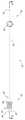
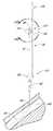
도 1a는 바늘, 확장기, 및 의료 제품과 동축으로 정렬된 프리로딩 가이드 와이어 섹션을 도시한, 본 발명에 따라 구성된 접근 장치의 양호한 실시예의 사시도이다.
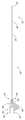
도 1b는 도 1a에 도시된 실시예의 평면도이다.
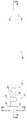
도 2a는 원위 단부 부근의 천공부를 도시한, 도 1a의 바늘의 평면도이다.
도 2b는 근위 단부 부근의 핀을 도시한, 도 1a의 바늘의 측면도이다.
도 2c는 도 2a의 라인 2C-2C를 따라 취해진 단면도이다.
도 2d는 천공부를 도시한, 도 2a의 바늘의 일부의 확대 평면도이다.
도 2e는 도 2a의 바늘의 바늘 허브의 확대 평면도이다.
도 2f는 도 2a의 바늘의 바늘 허브의 확대 측면도이다.
도 2g는 도 2a의 바늘의 바늘 허브의 확대 근위 단부도이다.
도 3a는 원위 단부 부근의 천공부를 도시한, 도 1a의 확장기의 평면도로서, 3a는 또한 확장기와 쉬스 사이로부터의 공기를 배출하기 위한 루어 표면의 종방향 정렬 홈들을 도시한다.
도 3b는 도 3a의 라일 3B-3B를 따라 취해진 단면도이다.
도 3c는 천공부 및 종방향 채널을 도시한, 도 3a의 확장기의 일부의 확대 평면도이다.
도 3d는 도 3a의 확장기 허브의 확대 단부도이다.
도 3e는 대응하는 스크류 나사부를 갖는 쉬스에 고정되도록 구성된 로킹 스핀 너트를 포함하는 확장기 허브의 다른 실시예의 사시도이다.
도 3f는 루어 표면의 원주 주위로 등가하게 이격된 홈들을 도시한, 도 3a의 라인 3F-3F를 따라 취해진 단면도이다.
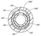
도 4a는 쉬스의 근위 단부에 연결된 쉬스 허브를 도시한, 도 1a의 쉬스의 평면도이다.
도 4b는 도 4a의 라인 4b-4b를 따라 취해진 단면도이다.
도 4c는 도 4a의 쉬스의 확대 단부도이다.
도 4d는 도 4a의 쉬스의 선단 부분의 확대 사시도이다.
도 5a는 가이드 와이어의 근위 단부에 연결된 가이드 와이어 허브를 도시한, 도 1a의 가이드 와이어 섹션의 사시도이다.
도 5b는 도 5a에 도시된 실시예의 가이드 와이어 섹션의 평면도이다.
도 6a는 도 1a의 트랙의 사시도이다.
도 6b는 확장기에 대해 바늘을 잠그기 위한 로킹 기구를 도시한, 도 6a의 트랙의 평면도이다.
도 6c는 도 6b의 트랙의 측면도이다.
도 6d는 도 6b의 로킹 기구의 확대도이다.
도 6e는 프리로딩 상태의 가이드 와이어 섹션을 잠그는 다른 로킹 기구의 확대도이다.
도 7a는 프리로딩 상태의 트랙에 잠겨진 가이드 와이어 섹션을 갖춘 도 6e의 로킹 기구를 도시한, 도 1a의 접근 장치의 평면도이다.
도 7b는 도 7a의 접근 장치 및 로킹 기구의 측면도이다.
도 7c는 트랙의 정지부와 요소 사이에 배치된 가이드 와이어 허브를 도시한, 도 7a의 접근 장치를 통한 단면도이다.
도 7d는 가이드 와이어 허브의 적어도 일부 주위로 트랙으로부터 연장하는 2개의 아암을 도시한 도 7b의 접근 장치의 확대 단면도이다.
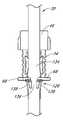
도 8a는 접근 장치의 원위 단부를 환자로의 삽입을 도시한, 도 1a에 도시된 실시예의 평면도이다.
도 8b는 환자에 인접한 접근 장치의 영역을 명확하게 나타낸 도 8a에 도시된 실시예의 확대도이다.
도 8c는 숨겨진 라인의 천공부 또는 확장기 개구와 정렬된 천공부 또는 바늘 개구를 도시한, 도 8b의 도시된 실시예의 일부의 확대도이다.
도 8d는 바늘의 내부로부터 쉬스와 확장기 사이에 형성된 채널로 유체가 유동하도록, 천공부 또는 확장기 개구와 정렬된 천공부 또는 바늘 개구를 도시한, 도 8c에 도시된 실시예의 일부의 확대 단면도이다.
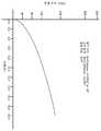
도 8e는 유체가 0.0508 mm(0.002 인치)의 갭 높이 폭을 갖춘 채널로 끌어 올려지는 속도를 도시한 그래프이다.
도 8f는 유체가 0.0254 mm(0.001 인치)의 갭 높이 폭을 갖춘 채널로 끌어 올려지는 속도를 도시한 그래프이다.
도 8g는 유체가 0.0127 mm(0.0005 인치)의 갭 높이 폭을 갖춘 채널로 끌어 올려지는 속도를 도시한 그래프이다.
도 8h는 확장기의 채널의 원위 구역을 통해 취해진 도 8c에 도시된 실시예의 일부의 확대 단면도이다.
도 8i는 바늘 허브가 제1 위치에 있을 때 바늘 허브가 확장기 허브에 잠겨지는 영역을 명확하게 나타낸, 도 8a에 도시된 실시예의 확대도이다.
도 8j는 도 8i에 도시된 실시예의 단면도이다.
도 9a는 바늘 팁으로부터 원위 방향으로 전진된 가이드 와이어를 도시한 도 1a에 도시된 실시예의 측면도이다.
도 9b는 바늘 허브가 제1 위치에 있을 때 가이드 와이어 허브가 바늘 허브에 잠겨지는 영역을 명확하게 나타낸, 도 9a에 도시된 실시예의 확대도이다.
도 9c는 도 9b에 도시된 실시예의 단면도이다.
도 10a는 도 9a에 도시된 부분으로부터 바늘 본체에 대해 원위로 전진된 쉬스 및 확장기를 도시한, 도 1a에 도시된 실시예의 측면도이다.
도 10b는 바늘 허브가 제2 위치에 있을 때 바늘 허브가 트랙에 잠겨지는 영역을 명확하게 나타낸, 도 10a에 도시된 실시예의 확대 후면도이다.
도 11a는 쉬스로부터 가이드 와이어, 바늘 본체, 및 확장기의 제거를 도시한, 도 1a에 도시된 실시예의 측면도이다.
도 11b는 쉬스로부터의 가이드 와이어, 바늘 본체, 및 확장기의 제거 동안 확장기에 의해 커버된 바늘 팁을 도시한, 도 11a에 도시된 실시예의 부분의 확대도이다.
도 12a는 확장기 및 바늘의 천공부 또는 정렬된 개구의 다른 실시예를 도시한 확대 평면도이다.
도 12b는 바늘의 내부로부터 쉬스와 확장기 사이에 형성된 채널로 유체가 유동하도록 천공부 또는 확장기 개구와 정렬된 천공부 또는 바늘 개구를 도시한, 도 12a의 라인 13B-13B를 따른 확대 단면도이다.
도 13a는 확장기 및 바늘의 천공부 또는 정렬된 개구의 다른 실시예를 도시한 확대 평면도이다.
도 13b는 바늘의 내부로부터 쉬스와 확장기 사이에 형성된 채널로 유체가 유동하도록, 천공부 또는 확장기 개구와 정렬된 천공부 또는 바늘 개구를 도시한, 도 13a의 라인 13B-13B를 따른 확대 단면도이다.
도 14a는 확장기와 쉬스 사이에 형성된 채널의 다른 실시예를 도시한 확대 평면도이다.
도 14b는 쉬스로 연장하는 채널의 두께를 도시한, 도 14a의 라인 14B-14B를 따른 단면도이다.
도 15a는 확장기와 쉬스 사이에 형성된 채널의 다른 실시예를 도시한 확대 평면도이다.
도 15b는 확장기와 쉬스 모두로 연장하는 채널의 두께를 도시한, 도 15a의 라인 15B-15B를 따른 단면도이다.
도 16a는 확장기와 쉬스 사이에 형성된 채널의 다른 실시예를 도시한 확대 평면도이다.
도 16b는 확장기로 연장하는 키홈의 형태의 등가하게 이격된 복수의 채널을 도시한, 도 15a의 라인 16B-16B를 따른 단면도이다.
도 17은 다른 형상을 갖는 확장기와 쉬스 사이에 형성된 채널을 도시한, 접근 장치의 다른 실시예를 통한 확대 단면도이다.
도 18은 바늘의 다른 실시예의 측면도이다.
도 19는 도 18의 바늘의 원위 단부의 확대도이다.These and other features, aspects, and advantages of the access devices described herein are described below with reference to the drawings of the preferred embodiments, which are not intended to limit the invention described as an example of the invention. Moreover, the same reference numerals between the drawings are used to denote the same parts of the illustrated embodiment. The same parts between the illustrated embodiments are similarly represented by the same reference numerals combined with additional letters to indicate other embodiments. Brief description of each of the drawings is as follows.
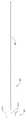
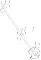
1A is a perspective view of a preferred embodiment of an access device constructed in accordance with the present invention, showing a needle, dilator, and preloading guide wire section coaxially aligned with a medical product.
1B is a top view of the embodiment shown in FIG. 1A.
FIG. 2A is a plan view of the needle of FIG. 1A, showing a perforation near the distal end. FIG.
FIG. 2B is a side view of the needle of FIG. 1A showing the pin near the proximal end. FIG.
2C is a cross sectional view taken along the
2D is an enlarged plan view of a portion of the needle of FIG. 2A, showing the perforation.
FIG. 2E is an enlarged plan view of the needle hub of the needle of FIG. 2A.
FIG. 2F is an enlarged side view of the needle hub of the needle of FIG. 2A.
FIG. 2G is an enlarged proximal end view of the needle hub of the needle of FIG. 2A.
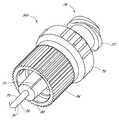
FIG. 3A is a plan view of the dilator of FIG. 1A showing the periphery near the distal end, and 3A also shows longitudinal alignment grooves of the luer surface for evacuating air from between the dilator and the sheath.
3B is a cross-sectional view taken along
3C is an enlarged plan view of a portion of the dilator of FIG. 3A, showing the perforations and longitudinal channels.
3D is an enlarged end view of the dilator hub of FIG. 3A.
3E is a perspective view of another embodiment of an expander hub that includes a locking spin nut configured to be secured to a sheath with a corresponding screw thread.
3F is a cross-sectional view taken along
4A is a top view of the sheath of FIG. 1A showing a sheath hub connected to the proximal end of the sheath.
4B is a cross-sectional view taken along line 4b-4b of FIG. 4A.
4C is an enlarged end view of the sheath of FIG. 4A.
4D is an enlarged perspective view of the tip portion of the sheath of FIG. 4A.
FIG. 5A is a perspective view of the guide wire section of FIG. 1A showing a guide wire hub connected to the proximal end of the guide wire. FIG.
FIG. 5B is a top view of the guide wire section of the embodiment shown in FIG. 5A.
6A is a perspective view of the track of FIG. 1A.
FIG. 6B is a top view of the track of FIG. 6A showing the locking mechanism for locking the needle against the dilator. FIG.
6C is a side view of the track of FIG. 6B.
FIG. 6D is an enlarged view of the locking mechanism of FIG. 6B.
6E is an enlarged view of another locking mechanism for locking the guide wire section in the preloading state.
FIG. 7A is a top view of the access device of FIG. 1A showing the locking mechanism of FIG. 6E with a guide wire section submerged in a track in a preloaded state. FIG.
FIG. 7B is a side view of the access device and locking mechanism of FIG. 7A. FIG.
FIG. 7C is a cross sectional view through the access device of FIG. 7A showing a guide wire hub disposed between the stop of the track and the element; FIG.
FIG. 7D is an enlarged cross-sectional view of the access device of FIG. 7B showing two arms extending from the track around at least a portion of the guide wire hub. FIG.
FIG. 8A is a top view of the embodiment shown in FIG. 1A showing insertion of the distal end of the access device into the patient. FIG.
FIG. 8B is an enlarged view of the embodiment shown in FIG. 8A clearly showing the area of the access device adjacent to the patient.
FIG. 8C is an enlarged view of a portion of the depicted embodiment of FIG. 8B showing the aperture or needle opening aligned with the aperture or dilator opening of the hidden line.
FIG. 8D is an enlarged, cross-sectional view of a portion of the embodiment shown in FIG. 8C showing the aperture or needle opening aligned with the aperture or dilator opening such that fluid flows from the interior of the needle into the channel formed between the sheath and the dilator.
8E is a graph showing the rate at which fluid is drawn up into a channel with a gap height width of 0.0508 mm (0.002 inches).
FIG. 8F is a graph showing the rate at which fluid is drawn up into a channel with a gap height width of 0.0254 mm (0.001 inch).
FIG. 8G is a graph showing the rate at which fluid is drawn up into a channel with a gap height width of 0.0127 mm (0.0005 inches).
FIG. 8H is an enlarged cross-sectional view of a portion of the embodiment shown in FIG. 8C taken through the distal region of the channel of the dilator.
FIG. 8I is an enlarged view of the embodiment shown in FIG. 8A, clearly showing the area where the needle hub is locked to the dilator hub when the needle hub is in the first position. FIG.
8J is a cross-sectional view of the embodiment shown in FIG. 8I.
FIG. 9A is a side view of the embodiment shown in FIG. 1A showing a guide wire advanced distal from a needle tip. FIG.
FIG. 9B is an enlarged view of the embodiment shown in FIG. 9A, clearly showing the area where the guide wire hub is locked to the needle hub when the needle hub is in the first position. FIG.
9C is a cross-sectional view of the embodiment shown in FIG. 9B.
10A is a side view of the embodiment shown in FIG. 1A showing the sheath and dilator advanced distal to the needle body from the portion shown in FIG. 9A.
FIG. 10B is an enlarged rear view of the embodiment shown in FIG. 10A, clearly showing the area where the needle hub is locked to the track when the needle hub is in the second position.
FIG. 11A is a side view of the embodiment shown in FIG. 1A showing removal of the guide wire, needle body, and dilator from the sheath. FIG.
FIG. 11B is an enlarged view of the portion of the embodiment shown in FIG. 11A, showing the guide wire from the sheath, the needle body, and the needle tip covered by the dilator during removal of the dilator. FIG.
12A is an enlarged plan view illustrating another embodiment of perforations or aligned openings in the dilator and needle.
12B is an enlarged cross-sectional view along
13A is an enlarged plan view showing another embodiment of perforations or aligned openings in the dilator and needle.
FIG. 13B is an enlarged cross-sectional view along
14A is an enlarged plan view illustrating another embodiment of a channel formed between the dilator and the sheath.
14B is a cross sectional view along
15A is an enlarged plan view showing another embodiment of a channel formed between the dilator and the sheath.
15B is a cross sectional view along
16A is an enlarged plan view showing another embodiment of a channel formed between the dilator and the sheath.
16B is a cross-sectional view along
17 is an enlarged cross-sectional view through another embodiment of an access device, showing a channel formed between an expander and a sheath having a different shape.
18 is a side view of another embodiment of a needle.
19 is an enlarged view of the distal end of the needle of FIG. 18.
본 발명의 기재는, 혈관 또는 배출 부위로의 의료 제품(예를 들어, 카테터 또는 쉬스)의 운반을 위한 접근 장치를 제공한다. 도 1a는 본 발명의 양호한 실시예에 따라 혈관(예를 들어, 정맥 또는 동맥)로 삽입되도록 구성된 접근 장치(20)를 도시한다. 접근 장치는 이러한 용도로(관 접근을 위해) 후술되었지만, 접근 장치는 또한 의료 제품(예를 들어, 카테터 또는 쉬스)을 환자의 몸통(예를 들어, 배출 부위) 내의 다른 위치에 위치시키고 접근시키는데, 또는 다른 목적[예를 들어, 고름집(abscess)의 배출를 위해]을 위해 사용될 수도 있다.The present disclosure provides an access device for the delivery of a medical product (eg, catheter or sheath) to a blood vessel or discharge site. 1A shows an
접근 장치의 본 발명의 실시예는 환자 내의 몸통 공간에 예시적인 단일편의 관형 의료 제품을 위치시키는 맥락에서 기재된다. 일단 위치되면, 관형 제품은, 이후 몸통 공간으로의 접근을 제공하기 위해 다른 의료 제품(예를 들어, 카테터, 가이드 와이어 등)을 수용하는데 사용될 수 있고 및/또는 몸통 공간으로부터의 유체의 제거(예를 들어, 배출) 또는 몸통 공간으로의 유체의 도입을 위한 통로를 제공하는데 사용될 수 있다. 예시된 실시예에서, 관형 의료 제품은 유체를 주로 정맥으로 통과시키도록 구성된 쉬스 또는 카테터이다. 그러나, 본 발명의 원리는 단일편 쉬스 또는 카테터의 배치나, 쉬스 또는 카테터를 통한 의료 제품의 연속적인 삽입으로 제한되지 않는다. 대신, 본 발명의 기재의 관점에서, 당업자라면, 본원에 기재된 접근 장치가 또한,다른 종류의 쉬스, 유체 배출 및 운반 튜브, 및 환자에 집접적으로 위치되는 또는 다른 의료 제품을 통해 간접적으로 위치되는 단일 또는 다중 루멘 카테터를 포함하는 하나 이상의 다른 종류의 의료 제품을 위치시키는 것과 관련하여 성공적으로 이용될 수 있다는 것을 이해할 것이다.Embodiments of the present invention of an access device are described in the context of placing an exemplary single tubular medical product in the torso space within a patient. Once positioned, the tubular product can then be used to receive another medical product (eg, catheter, guide wire, etc.) to provide access to the trunk space and / or removal of fluid from the trunk space (eg For example) to provide a passageway for the introduction of fluid into the body space. In the illustrated embodiment, the tubular medical product is a sheath or catheter configured to primarily pass fluid into the vein. However, the principles of the present invention are not limited to the placement of single piece sheaths or catheters or the continuous insertion of medical products through the sheaths or catheter. Instead, in view of the description of the present invention, those skilled in the art will also appreciate that the access devices described herein may also be placed indirectly through other types of sheaths, fluid drainage and delivery tubes, and patients or indirectly through other medical products. It will be appreciated that it may be used successfully in connection with positioning one or more other types of medical products, including single or multiple lumen catheter.
예컨대, 제한되는 것은 아니지만, 본원에 기술된 접근 장치는 중심 정맥 카테터, 말초 삽입형 중심 카테터, 투석 카테터, 수술 배액 튜브, 찢을 수 있는 쉬스(tear-away sheath), 다중 편 쉬스, 스코프(scope)뿐만 아니라, 외부 또는 내장 전자 장치 또는 센서에 연결되는 와이어 또는 케이블을 위한 전기 도관을 직접적으로 또는 간접적으로 위치시키도록 또한 구성될 수 있다. 전술된 바와 같이, 상기에 나열된 의료 제품은 접근 장치의 확장기, 바늘 및 가이드 와이어를 통해 환자 내에 직접적으로 위치될 수 있거나, 이어서 접근 장치의 확장기, 바늘 및 가이드 와이어를 통해 환자 내에 있는 의료 제품을 통해 환자 내에 위치될 수 있다.For example, but not by way of limitation, the access devices described herein include, but are not limited to, central venous catheter, peripherally inserted central catheter, dialysis catheter, surgical drainage tube, tear-away sheath, multiple piece sheath, scope In addition, it may also be configured to directly or indirectly position electrical conduits for wires or cables connected to external or embedded electronic devices or sensors. As mentioned above, the medical products listed above may be placed directly in the patient through the expander, needle and guide wire of the access device, or subsequently through the medical product in the patient through the expander, needle and guide wire of the access device. It can be located in the patient.
또한, 본원에 기술된 실시예는 단일 의료 제품의 동축 삽입에 제한되지 않는다. 예컨대, 2개의 카테터는 삽입된 쉬스를 통해 환자에 삽입될 수 있거나, 제2 카테터는 삽입된 제1 카테터를 통해 환자에 삽입될 수 있다. 또한, 혈관 또는 신체 공간 내로의 도관을 제공하는 것 이외에, 확장기, 바늘 및 가이드 와이어를 통해 삽입되는 의료 제품은 후속하여 삽입된 의료 제품의 루멘(들)에 더하여 있는 루멘을 형성할 수 있다. 당해 분야의 숙련자는 본원에 기술된 시스템 및 장치를 위한 추가 용례를 또한 알 수 있다. 따라서, 쉬스와 관련된 접근 장치의(예컨대 마이크로 천공 용례를 위한) 도시 및 예시는 접근 장치의 한가지 가능한 용례의 예시일 뿐이다.In addition, the embodiments described herein are not limited to the coaxial insertion of a single medical product. For example, two catheters may be inserted into a patient through an inserted sheath or a second catheter may be inserted into a patient through an inserted first catheter. In addition, in addition to providing a conduit into the vessel or body space, the medical product inserted through the dilator, needle and guide wire may form a lumen in addition to the lumen (s) of the subsequently inserted medical product. One of ordinary skill in the art would also recognize additional applications for the systems and devices described herein. Thus, illustrations and examples of access devices associated with sheaths (eg for microperforation applications) are merely examples of one possible application of access devices.
도 1a 및 도 1b는 접근 장치(20)의 바람직한 실시예를 도시한다. 접근 장치(20)는 바늘(22), 확장기(24) 및 쉬스(26)를 포함한다. 도시된 실시예에서, 접근 장치는 가이드 와이어 섹션(28) 및 트랙(30)도 포함한다. 도 1b에 가장 잘 보이는 바와 같이, 확장기(24)는 바늘(22) 상에 동축으로 바람직하게 장착되고, 쉬스(26)는 확장기(24) 상에 동축으로 장착된다. 접근 장치의 구성요소들의 삽통(telescoping) 특성은 구성요소들을 동축이 아니라 대체로 평행하게 배열된 축(예컨대 모노레일 타입 설계)에 배열함으로써 또한 달성될 수 있다.1A and 1B show a preferred embodiment of the
이들 구성요소들 각각은 말단부 또는 전이부(즉, 허브)에서 루미날 피팅부(luminal fitting)를 포함하고 피팅부로부터 연장되는 기다란 구조체를 포함한다. 따라서, 도시된 실시예에서, 바늘(22)은 바늘 허브(34)로부터 말단으로 연장되는 바늘 본체(32)를 포함하고, 확장기(24)는 확장기 허브(38)로부터 말단으로 연장되는 확장기 샤프트(36)를 포함하고, 쉬스(26)는 쉬스 허브(42)로부터 말단으로 연장되는 쉬스 본체(40)를 포함한다. 가이드 와이어 섹션(28)은 가이드 와이어(44)를 포함하고 바람직하게는 가이드 와이어 허브 또는 캡(46)을 포함한다. 도시된 실시예에서 가이드 와이어 허브(46)는 가이드 와이어(44)의 근위 단부에 배치되지만, 다른 용례에서 허브(46)는 가이드 와이어(44)의 단부들 사이의 위치에 배치될 수 있다.Each of these components includes an elongate structure that includes a luminal fitting at the distal end or transition (ie a hub) and extends from the fitting. Thus, in the illustrated embodiment, the
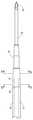
도 2a 내지 도 2g는 접근 장치의 바람직한 실시예에 따라 구성되는 바늘(22)의 바늘 본체(32) 및 바늘 허브(34)를 접근 장치(20)의 다른 구성요소들과 분리하여 도시한다. 도 2a 및 도 2b에 가장 잘 보이는 바와 같이, 바늘 허브(34)는 바늘 본체(32)의 근위 단부에 배치된다. 바늘 본체(32)는 바늘(22)의 원위 부분(50) 근처의 원위 단부에서 종결하고, 바늘 허브(34)는 바늘(22)의 근위 부분(52)에 있다.2A-2G show the
바늘 본체(32)는 원형이고 일정한 직경을 갖는 내경 보어 및 원형이고 일정한 직경을 갖는 외부 표면을 갖는 기다란 관 형상을 바람직하게 갖는다. 그러나, 다른 실시예에서, 바늘 본체(32)는 (예컨대, 제한되지는 않지만 타원 단면 형상과 같은) 다른 외부 형상 및 보어를 가질 수 있다. 바늘의 내부 또는 외부는 또한 홈 또는 채널을 포함할 수 있다. 홈 또는 채널은 바늘(22) 내에 (예컨대 가이드 와이어 주위에) 또는 바늘(22)의 일정 구조체로 또는 그 주위에 바늘 내에 유체를 안내할 수 있다. 몇몇 실시예에서, 홈 또는 채널은 확장기에 대해 바늘(22)의 바람직한 배향을 유지하는 것을 도울 수 있다.The
바늘 본체(32)는 표적 피하 신체 공간에 접근하기에 충분히 긴 길이를 갖고, 과도한 외상을 야기하지 않으면서 신체 공간에 접근할 때 삽입력에 저항하기에 충분한 게이지 크기를 갖는다. 많은 용례에서, 바늘 본체는 3 내지 20 cm이고 더 바람직하게는 3 내지 10 cm인 길이를 가질 수 있다. 예컨대, 성인의 흉부의 신체 공간(예컨대 혈관)에 접근하기 위해, 바늘 본체(32)는 바람직하게는 7 cm 이상인 길이를 갖고, 더 바람직하게는 9 cm 이상인 길이를 갖고, 가장 바람직하게는 9 내지 10 cm인 길이를 갖는다. 바늘의 치수는 바람직하게는 18 게이지 이하이고, 더 바람직하게는 18 내지 28 게이지이고, 마이크로 천공 용례(micro-puncture application)[말초 IVs(peripheral IVs)]에서 가장 바람직하게는 18 내지 26 게이지이다. 신생아에 대한 용례에 있어서, 바늘 본체(32)의 길이 및 게이지는 상당히 짧고 작아야 하고, 예컨대 바람직하게는 3 내지 4 cm이고 26 내지 28 게이지이다.The
도 2a 및 도 2d에 가장 잘 보이는 바와 같이, 바늘 본체(32)는 바늘 본체(32)의 원위 단부 근처에 적어도 하나의 천공부 또는 개구(56)를 포함한다. 천공부(56)는 바늘 본체(32)의 벽을 통해 연장되고 이하에 기술될 바와 같이 바늘 본체(32)에 대한 다양한 형상 및 배향을 가질 수 있다. 더욱이, 바늘 본체(32)는 원위 부분(50)에 배치되는 경사 팁(54; bevel tip)을 가질 수 있다.As best seen in FIGS. 2A and 2D, the
도 2a 및 도 2b에 도시된 바와 같이, 휜(58)은 바늘 내의 개구 또는 천공부(56) 및 바늘 팁 상의 경사부의 원주 방향 위치에 정렬되는 바늘 허브(34) 주위의 원주 방향 위치에 바람직하게 배치된다. 즉, 휜(58)은 경사부 및 천공부로 인덱스된다. 사용 중에, 의사 또는 의료인은 경사부가 혈관 내측에 있고 천공부가 쉬스 및/또는 확장기에 의해 덮어지더라도 노출된 휜(58)의 배향을 주의함으로써, 경사진 바늘 팁 [및 천공부(56)]의 배향을 결정할 수 있다. 예컨대, 도시된 실시예에서, 환자로부터 멀리 있는 휜(58)의 배향은 혈관 내의 바늘 팁의 상향 경사 배향(bevel up orientation)과 일치한다. 또한, 도 2c에 도시된 바와 같이 천공부(56)는 휜(58)과 동일한 측에 있다.As shown in FIGS. 2A and 2B, the
휜(58)은 바늘 허브(34)를 조작하기 위해 파지 영역을 또한 제공한다. 예컨대, 의사 또는 의료인은 확장기(24) 및/또는 쉬스(26)에 대해 바늘 허브(34)를 안정화하기 위해 휜(58)의 측부 상에 검지 손가락 및 엄지 손가락을 위치시킬 수 있다. 도시된 실시예에서, 확장기/쉬스가 바늘 위에서 말단으로 활주함에 따라, 바늘 허브(34)는 제1 위치(121)와 제2 위치(123)(도 6a에 도시된 예시 부분) 사이에서 트랙(30)을 따라 상대적으로 활주한다. 휜(58)은 (이하에 설명될) 삽입 단계를 수행할 때 유지될 수 있다. 더욱이, 휜(58)은 확장기 허브(38)를 회전시키는 동안에 바늘 허브(34)를 안정화하는데 사용될 수 있다. 또한, 휜(58)은 바늘 허브(34)가 트랙(30)을 따라 임의의 위치에 배치될 때 접근 장치(20)를 파지하도록 돕는 보조 장치로서 의사 또는 의료인에 의해 사용될 수 있다.
도 2d는 바늘 본체(32) 내의 측부 개구 또는 천공부(56)의 확대도이다. 하나 이상의 천공부(56)는 바늘 본체(32)의 측부를 통과하는 경로를 제공한다. 도 2d에 도시된 천공부(56)는 장원형(oblong) 형상을 갖는다. 그러나, 측부 개구(56)의 형상은 도시된 실시예에 제한되지 않고, 둥근 형상, 장원형 형상, 정사각형 형상 또는 다른 형상일 수 있다.2D is an enlarged view of the side opening or
이제 특별히 도 2e 내지 도 2g를 참조하면, 바늘 허브(34)는 바늘 허브(34)의 근위 부분 및 원위 부분에서 로킹 구조체를 바람직하게 포함한다. 이들 로킹 구조체들은 루어-나사형(luer-thread-type) 또는 다른 유형의 연결부일 수 있다.Referring now particularly to FIGS. 2E-2G, the
바늘 허브(34)의 근위 부분(52) 상의 로킹 구조체는 의사 또는 의료인이 바늘 허브(34)의 근위 단부에 다른 의료 제품을 고정시킨다. 예컨대, 도시된 실시예의 바늘 허브(34)는 환형 플랜지 또는 립(63)을 포함한다. 립(63)은 바늘 허브(34)가 대응 루어-너트 로킹 특징부를 갖는 다른 의료 제품에 부착되게 하도록 나사 결합된다. 부가적으로, 의사 또는 의료인은 필요에 따라 다른 절차를 수행하기 위해 근위 단부 상의 로킹 구조체에 주사기 또는 모니터링 장비를 부착할 수 있다. 바늘 허브(34)는 이들 특징부가 특정 용례에 바람직하다면 근위 단부 및/또는 측부 포트에서 격벽(septum)을 또한 포함할 수 있다.The locking structure on the
바늘 허브(34)의 말단부 상의 로킹 구조체는 예컨대 바늘 허브(34)가 제1 위치(121)에 있을 때 의사 또는 의료인이 바늘 허브(34)를 확장기 허브(38)에 로킹하게 한다. 도시된 실시예에서, 로킹 구조체는 바늘 허브(34) 상에 래치 요소(66)를 포함한다. 래치 요소(66)는 바늘 허브(34)를 확장기 허브(38)에 해제 가능하게 로킹한다. 로킹 구조체는 의료인이 바늘 허브(34) 또는 확장기 허브(38) 또는 이들 양자 모두를 파지하면서 환자 내로 바늘을 전진시킨다.The locking structure on the distal end of the
아래에 더 상세히 설명될 바와 같이, 가이드 와이어(44)는 바늘 허브(34)의 중공부(62)를 통해, 바늘 본체(32)를 통해, 그리고 천공된 혈관 내로 도입된다. 가이드 와이어(44)는 의료인이 확장기(24) 및 쉬스(26)를 혈관 내로 안내하게 한다.As will be explained in more detail below, the
바늘 허브(34)는 제1 위치(121)와 제2 위치(123) 사이에서 트랙(30)을 따라 바늘 허브(34)를 활주하게 하는 2개의 탱(68; tang)을 또한 포함할 수 있다. 바람직한 실시예에서 바늘 허브(34)의 2개의 탱(68)이 제1 위치(121)와 제2 위치(123) 사이에서 트랙(30)과 결합하지만, 다른 실시예에서는 바늘 허브(34)는 제1 위치(121)와 제2 위치(123) 사이의 트랙(30)의 길이의 일부에 걸쳐서만 트랙(30)과 결합된다. 트랙(30)과 바늘 허브(34) 사이의 활주 상호 연결은 또한 다른 협동 구조체[예컨대 더브테일(dovetail) 연결의 대응하는 핀 및 테일(tail)]을 사용하여 달성될 수 있다.
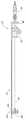
도 3a는 도 1a에 도시된 실시예의 확장기(24)의 평면도이다. 도 3b는 선(3B-3B)을 따라 취해진, 도 3a에 도시된 실시예의 확장기(24)의 단면도이다. 도 3a 및 도 3b에 도시된 바와 같이, 도시된 확장기(24)는 확장기 샤프트(36), 확장기 허브(38), 원위 영역(70) 및 근위 영역(72)을 포함한다. 도시된 실시예에서 확장기 샤프트(36)는 측부 개구 또는 천공부(74)를 포함하지만, 다른 실시예에서 확장기 샤프트(36)는 더 적거나 더 많은 개수의 천공부(74)를 포함할 수 있다. 예컨대, 확장기 샤프트(36)는 (아래에 더 상세히 설명될 바와 같이) 혈액 플래쉬 챔버(들)이 확장기 내에 배치되는 천공부(74)를 포함할 수 없다.3A is a top view of the
확장기 허브(38)는 하나 이상의 통기구(vent)를 포함할 수 있다. 도시된 실시예에서, 확장기 허브(38)의 통기구는 홈(75)에 의해 형성된다. 부가적으로, 확장기 샤프트(36)는 확장기 샤프트(36)의 외부 표면에 형성되는 하나 이상의 길이방향 채널을 포함할 수 있다. 도시된 실시예에서, 채널은 개방 채널이다. 개방 채널의 측벽들은 릿지(76)들에 의해 형성된다. 도시된 실시예에서 릿지(76)는 쉬스(26)와 접촉하는 대체로 부드럽고 아치형인 외부 표면을 형성하지만, 다른 실시예에서 릿지는 다른 형상을 가질 수 있다(예컨대 더 과도한 정점들을 형성할 수 있다). 일단 쉬스 본체(40) 내에 조립되면, 확장기 샤프트(36)의 개방 채널은 쉬스 본체(40)의 내경에 의해 폐쇄된다.The
도 3c는 도 3a에 도시되어 있는 실시형태의 일부에 대한 확대 평면도이다. 앞서 언급한 바와 같이, 도시되어 있는 확장기 샤프트(36)는 릿지(76) 사이에 형성되어 있는 하나 이상의 채널과 하나 이상의 측부 개구(74)를 포함하고 있다. 측부 개구 또는 천공부(74)는 확장기 샤프트(36)의 측부를 관통하는 유체 경로를 제공한다. 측부 개구(74)의 형상은 도시되어 있는 실시형태에 한정되는 것은 아니고, 둥근형, 타원형, 사각형 또는 다른 형상을 가질 수 있다. 도 3c에 도시되어 있는 천공부(74)의 개구는 타원형을 갖고 있다.FIG. 3C is an enlarged plan view of a portion of the embodiment shown in FIG. 3A. As mentioned above, the
도시되어 있는 실시형태에 있어서, 확장기 샤프트(36)의 개구(74)는 타원형 형상을 갖고 있고, 그 주축은 바늘(22)의 타원형 개구(56)의 주축에 대해 평행하지 않다. 예를 들어, 바늘 개구(56)는 종방향으로 연장될 수 있고, 확장기 개구(74)는 원주방향으로 연장될 수 있고, 또는 그 반대일 수도 있다. 환언하면, 확장기 개구(74)의 종축은 바늘 개구(56)의 종축에 일반적으로 수직하게 배치되어 있다. 이하의 추가의 실시형태에 관련하여 설명하는 바와 같이, 이 개구(56, 76)는 바람직하게는 제조 공차 및 회전 오정렬을 일으키는 상당한 정도의 중첩을 얻는 다른 형상, 크기 및 배향을 가질 수 있다. 이러한 이유 때문에, 천공부 중 하나가 적어도 하나의 방향에서 동일한 방향의 천공부의 다른 하나보다 더 큰 치수를 갖는 것이 바람직하다. 따라서, 도시되어 있는 실시형태에 있어서, 바늘 천공부(56)는 확장기 천공부(74)의 종방향 치수보다 더 긴 종방향 치수를 갖는다.In the embodiment shown, the
릿지(76) 사이에 형성된 채널은 개구(74)의 말단 지점으로부터 근위 방향으로 연장된다. 도시되어 있는 실시예의 릿지(76)는 쉬스 내에서 확장기 샤프트(36)를 균형을 잡도록 확장기 샤프트(36)를 따라서 확장기 샤프트(36)의 대향측 상에 배치되어 있다. 도시되어 있는 실시형태에 있어서, 릿지(76)는 그 사이에 2개의 채널을 형성한다. 쉬스 내에서 확장기를 균형을 잡으면 확장기는 쉬스의 내측 원주부에 균일한 압력을 가하게 된다.The channel formed between the
확장기 허브(38)는 확장기(24)의 원위 영역과 근위 영역(72)에 로킹 구조체를 포함할 수 있다. 각 로킹 구조체는 루어 타입 또는 다른 타입의 연결부일 수 있다. 도시되어 있는 실시형태에 있어서, 확장기 허브(38)는 제1 루어 연결부(78)와, 제2 루어 연결부(80)와, 립(77)과, 베이스(79)를 포함하고 있다. 제1 루어 연결부(78)는 도 2e에 도시되어 있는 바늘(22) 상의 바늘 허브(34)에 맞물려 있다. 제2 루어 연결부(80)는 제1 루어 연결부(78) 말단에 배치되어 있다. 소정의 실시형태에 있어서, 제2 루어 연결부(80)(예를 들어, 수형 루어 슬립 커넥터)는 도 1a에 도시되어 있는 쉬스(26) 상의 쉬스 허브(42)(예를 들어, 암형 루어 슬립 커넥터)에 맞물리도록 구성될 수 있다. 추가로, 이 구성요소 상의 수형-암형 루어 슬립 커넥터는 반대로 될 수도 있다.The
도 3d는 도 3a의 확장기(24)의 확대 근위 단부도이다. 도 3d에 가장 명확하게 도시되어 있는 바와 같이, 확장기 허브(38)는 개구(82)를 포함하고 있는데, 이 개구는, 바늘 허브(34)가 제 1 위치(121)에 있을 때에, 바늘 허브(34)에 확장기 허브(38)를 고정하도록 도 2e 내지 도 2f에 도시되어 있는 바늘 허브(34) 상의 래치 요소(66)에 해제가능하게 맞물린다. 마찬가지로, 바늘 허브(34)와 확장기 상의 수형-암형 루어 슬립 커넥터는 다른 실시형태에서 반대로 될 수도 있다.3D is an enlarged proximal end view of the
확장기(24)의 색상은 혈액 또는 다른 유체와 확장기(24) 사이의 대조가 강화되도록 선택될 수 있다. 혈앨 플래쉬 동안에, 예를 들어, 혈액은 혈관 내의 바늘의 적절한 배치를 확실하게 하도록 확장기(24)와 쉬스 사이에서 흐르는 것으로 관찰된다. 유체의 가시성을 증가시키기 위해, 쉬스와 확장기(24) 사이에서 유체가 흐름에 따라, 쉬스는 깨끗한 또는 투명한 재료로 제조되고, 확장기(24)는 유체의 색상과 대조되는 색상을 가지는 것이 바람직하다. 예를 들어, 확장기(24)는 적색의 혈액과의 대조를 촉진시키기 위해 백색을 가질 수 있다. 유체의 색상 및 원하는 대조도(degree of contrast)에 따라서 확장기(24)의 다른 색상이 채용될 수 있다. 또한, 혈액 플래쉬의 영역 내의 확장기의 일부가 상이한 색상을 갖는 나머지 부분과 대조되는 색상을 가질 수 있다. 바늘과 확장기(24) 사이에 형성된 채널을 갖는 실시형태에 있어서, 확장기(24)는 쉬스와 유사한 깨끗한 또는 투명한 재료로 제조되어, 외과의사가 쉬스와 확장기(24)를 통해 혈액 플래쉬를 관찰할 수 있게 한다.The color of the
도 3e는 확장기 허브(38A)의 다른 실시형태에 대한 확대 사시도이다. 확장기 허브(38A)는, 확장기 허브(38A)가 스핀 너트 또는 칼라(84)를 더 포함하고 있는 점을 제외하고는, 도 3a에 도시되어 있는 확장기 허브(38)와 유사하다. 스핀 너트(84)의 근위 단부는 확장기 허브(38)(도 3a 참고) 내의 환형 홈(73)을 중심으로 회전한다. 일단 환형 홈(73) 내에 배치되면, 스핀 너트(84)는 원위 방향으로 이동하는 것이 방지되지만, 확장기 허브(38A)를 중심으로 자유롭게 회전할 수 있다. 스핀 너트(84)는 쉬스(26) 상의 대응하는 상호결합 요소에 로킹되는 상호결합 요소를 구비할 수 있다. 도시되어 있는 실시형태에 있어서, 스핀 너트(84)는 도 1a에 도시되어 있는 쉬스(26) 상의 쉬스 허브(42) 상의 외부 나사부와 맞물리는 내부 나사부를 포함하고 있다.3E is an enlarged perspective view of another embodiment of dilator hub 38A. The dilator hub 38A is similar to the
확장기(24) 또는 쉬스(26)는 개별적으로 또는 함께 하나 이상의 통로를 형성하여, 공기 또는 가스가 확장기(24)와 쉬스(26) 사이 및/또는 바늘과 확장기 사이로부터 배출 또는 배기될 수 있다. 또한, 하나 이상의 통로는 혈액과 같은 액체의 흐름을 방지하면서, 공기가 통과하는 것을 허용하는 크기를 가질 수 있다. 하나 이상의 통로는 쉬스(26)와, 쉬스 허브와, 확장기 허브(38)와, 확장기 샤프트의 노출부의 벽에 있을 수 있고, 및/또는 확장기(24)와 쉬스(26)의 인접한 표면들 사이에 형성되어 있을 수 있다. 예를 들어, 도 3a에는 쉬스(26)와 확장기(24)의 인접한 표면들 사이에 형성되어 있는 종방향으로 배열된 홈(75)이 도시되어 있다. 이러한 배기 통로는 미로(labyrinth)일 수 있다. 인접한 표면들은 쉬스(26)와 확장기(24) 사이에 루어 슬립 연결부를 형성한다.The
도 3f는 도 3a의 라인 3F-3F를 따라 취한 단면도이고, 도 3f에는 루어 슬립 표면의 외주부 둘레에 균일하게 이격되어 있는(균일하게 이격될 필요는 없음) 홈(75)이 도시되어 있다. 홈(75)은 혈액 플래쉬가 발생될 때에 쉬스와 같은 의료 물품과 확장기 사이로부터 공기가 배기될 수 있는 크기로 되어 있다. 전술한 바와 같이, 하나 이상의 통로는 표면 홈(75)의 형태로 되어 있을 필요는 없고, 대신에 개구 또는 통로의 형태일 수 있다.FIG. 3F is a cross-sectional view taken along
도시되어 있는 실시형태에 있어서, 하나 이상의 통로는 쉬스와 확장기 허브 사이의 루어 연결부를 통해 공기가 통과하는 것을 허용한다. 도시되어 있는 실시형태에 있어서, 통로(75)의 원위 단부가 루어 연결부의 원위측부 상에 배치되고, 통로(75)의 근위 단부는 루어 연결부의 근위 측부 상에 배치된다.In the embodiment shown, one or more passageways allow air to pass through the luer connection between the sheath and the dilator hub. In the embodiment shown, the distal end of the
하나 이상의 통로는 혈액 또는 다른 액체를 여과하는 크기로 되어 있을 수 있고, 또는 공기의 통과를 허용하면서 액체의 통과를 방지하는 필터 또는 다른 구조체를 포함할 수 있다. 예를 들어, 쉬스 자체는 소형 개구 형태의 하나 이상의 통로, 기공 또는 다공성 재료를 포함할 수 있다. 하나 이상의 통로의 크기와, 유체 분자의 예상 크기와, 성형된 요소(예를 들어, 적색 혈액 세포)에 따라, 쉬스 상의 하나 이상의 소형 개구, 기공 또는 다공성 재료가 공기는 통과시키지만 혈액은 보유시키는 다공성 통기부를 형성할 수 있다.One or more passages may be sized to filter blood or other liquids, or may include a filter or other structure that prevents passage of liquids while allowing passage of air. For example, the sheath itself may comprise one or more passageways, pores or porous materials in the form of small openings. Depending on the size of one or more passageways, the expected size of the fluid molecules, and the shaped element (eg, red blood cells), one or more small openings, pores, or porous materials on the sheath allow the air to pass but retain blood. A vent can be formed.
이제, 릿지형 확장기를 제조하는 방법을 설명하겠다. 첫째로, 압출 성형 공정을 사용하여 확장기의 기판 내에 또는 외경부(OD) 상에 하나 이상의 종방향 홈 또는 채널을 구비하는 긴 관형 본체를 제조한다. 긴 관형 본체는 단일 확장기의 필요한 길이를 초과하고, 바람직하게는 단일 확장기의 길이보다 여러 배 더 큰 길이를 갖는다. 압출 성형 공정에는 확장기의 내경 및 외경에 대한 원하는 기하학적 형상을 반영하는 기하학적 형상을 갖고 종방향 홈 또는 채널 또는 내부 채널의 원주방향 거리 및 두께를 갖는 제조 다이가 채용된다. 도 1 내지 도 11에 도시되어 있는 실시형태에 있어서, 긴 관형 본체는 쉬스 내에서 확장기의 균형을 강화하도록 본체의 대향측 상에 2개의 종방향 OD 채널을 포함하고 있다. 그러나, 단일 채널이 혈액 플래쉬용의 가시적인 표시기를 제공할 수 있다. 2개의 채널은 바람직하게는 압출 성형된 관형 본체의 길이를 따라 연장되어 있다. 도시되어 있는 실시형태는 확장기와 쉬스 사이에 배치된 하나 이상의 채널을 포함하고 있지만, 하나 이상의 채널은 추가로 또는 대안으로 바늘과 확장기 사이에, 확장기 내에, 및/또는 쉬스 내에 형성될 수 있다. 소정의 실시형태에 있어서, 확장기(24)는 이에 따라 채널 내의 유체 플래쉬를 가시화하도록 부분적으로 또는 전체적으로 깨끗한, 아투명, 투명, 또는 반투명 재료로 제조된다.Now, a method of manufacturing a ridge expander will be described. First, an extrusion process is used to produce an elongated tubular body having one or more longitudinal grooves or channels in the substrate of the dilator or on the outer diameter OD. The long tubular body exceeds the required length of a single dilator and preferably has a length several times greater than the length of a single dilator. The extrusion process employs a manufacturing die with a geometric shape that reflects the desired geometry for the inner and outer diameters of the expander and the circumferential distance and thickness of the longitudinal grooves or channels or inner channels. In the embodiment shown in FIGS. 1-11, the elongated tubular body includes two longitudinal OD channels on opposite sides of the body to enhance the balance of the dilator within the sheath. However, a single channel can provide a visible indicator for blood flash. The two channels preferably extend along the length of the extruded tubular body. While the illustrated embodiment includes one or more channels disposed between the dilator and the sheath, one or more channels may additionally or alternatively be formed between the needle and the dilator, in the dilator, and / or in the sheath. In certain embodiments, the
다시 도시되어 있는 실시형태를 참조하면, 압출 성형된 관형 본체는 단일 확장기용의 적절한 길이로 절단된다. 바람직한 방법에 있어서, 2개의 OD 홈은 절삭 확장기의 전체 길이부를 향해 연장된다.Referring again to the embodiment shown, the extruded tubular body is cut to the appropriate length for a single dilator. In a preferred method, the two OD grooves extend toward the full length of the cutting dilator.
그 후, 팁을 리폼하기 위해 절삭 확장기의 단부 상에 티핑 공정(tipping process)이 채용된다. 절삭 확장기의 단부가 마무리 가공된 확장기의 팁의 원하는 기하학적 형상과 정합하는 기하학적 형상을 갖는 다이/맨드렐로 강제된다. 원하는 기하학적 형상은 예를 들어 쉬스의 내경에 따라 선택된다. 쉬스 및 확장기가 팁 부근에서 억지 끼워맞춤 또는 밀봉을 형성하여 홈 확장기와 쉬스 사이에 형성된 채널 위에서 근위 방향의 혈액 흐름을 촉진시킨다. 바람직하게는, 팁 영역의 확장기의 OD는 원위 방향으로 테이퍼져 있다.Thereafter, a tipping process is employed on the end of the cutting expander to reform the tip. The end of the cutting dilator is forced into a die / mandrel with a geometry that matches the desired geometry of the tip of the finished dilator. The desired geometry is selected for example according to the inner diameter of the sheath. The sheath and dilator form an interference fit or seal near the tip to promote proximal blood flow over the channel formed between the groove dilator and the sheath. Preferably, the OD of the dilator of the tip region is tapered in the distal direction.
다이/맨드렐의 경우에 있어서, 열 에너지가 팁에 가해져서 팁을 다이/맨드렐과 정합하도록 리폼시킨다. 적외선 또는 RF 열원으로부터의 방사 가열을 사용하는 기법을 비롯한 임의의 공지된 기법에 의해 열 에너지가 가해진다. 티핑 공정의 일부로서, 팁 영역 내의 확장기는 홈이 대체로 제거되도록 리폼된다. 홈이 제거되면, 확장기는 팁 부근에서 쉬스와 억지끼워맞춤 또는 밀봉을 형성할 수 있다. 홈은 쉬스(26)의 팁이 확장기 상에 배치되는 위치의 근위 측부 상에서 확장기의 나머지 부분을 따라 유지된다. 다이/맨드렐로부터의 제거 후에, 확장기 팁 단부는 필요에 따라 임의의 제조 잔여물을 제거하도록 세정 및 절단될 수 있다.In the case of a die / mandrel, thermal energy is applied to the tip to reform the tip to mate with the die / mandrel. Thermal energy is applied by any known technique, including techniques that use radiant heating from infrared or RF heat sources. As part of the tipping process, the dilator in the tip region is reformed such that the groove is generally removed. Once the groove is removed, the dilator can form an interference fit or seal with the sheath near the tip. The groove is held along the rest of the dilator on the proximal side of the position where the tip of the
확장기 내의 하나 이상의 천공부는 팁 영역 부근 및 홈 내 또는 부근에서 확장기를 통해 절단된다. 각 천공부는 드릴 또는 레이저를 비롯한 임의의 공지된 수단에 의해 절단될 수 있다. 또한, 절단 장치는 천공부의 타원형 또는 다른 형상을 달성하도록 확장기에 대해 이동되거나, 그 반대로 될 수도 있다.One or more perforations in the dilator are cut through the dilator near the tip region and in or near the groove. Each perforation can be cut by any known means including a drill or a laser. Also, the cutting device may be moved relative to the dilator or vice versa to achieve an elliptical or other shape of the perforation.
팁으로부터 반대측에 있는 확장기의 단부는 확장기 상에서의 확장기 허브를 성형을 촉진시키도록 플레어형일 수 있다.The end of the dilator opposite the tip may be flared to facilitate shaping the dilator hub on the dilator.
도 4a는 도 1a에 도시된 실시예의 쉬스(26)의 평면도이다. 도 4b는 도 4a에 도시된 실시예의 쉬스(26)를 라인(4B-4B)을 따라 취한 단면도이다. 도 4c는 도 4a의 쉬스(26)의 근위 단부에서의 확대도이다. 도 4d는 도 4a의 쉬스(26)의 쉬스 허브(42)의 확대 사시도이다. 도 4a 내지 도 4d에 도시된 바와 같이, 쉬스(26)는 쉬스 본체(40), 쉬스 허브(42), 말단부(90) 및 선단 구역(92)을 포함할 수 있다. 쉬스 본체(40)는 부분적으로 또는 전체가 투명 재료, 아투명 재료, 또는 반투명한 재료로 제조될 수 있다. 또한, 쉬스 본체(40)는 예를 들면 바륨 셀페이트 스트라이프(barium sulfate stripe)와 같은 하나 이상의 불투과성 마커를 포함할 수 있다. 바람직한 실시예에서, 쉬스는 본체(40)의 정반대의 대향 측면에 배치된 2개의 이런 불투과성 스트립을 포함한다.4A is a top view of the
쉬스 본체(40)는 일체형 쉬스일 수 있으며, 이를 통해 카테터 또는 다른 의료 제품(예컨대, 가이드 와이어)이 혈관으로 삽입된다. 바람직한 실시예에서, 쉬스 본체(40)는 카테터 또는 다른 의료 제품(예컨대, 가이드 와이어)의 삽입을 위한 도관을 형성한다. 도관을 제공하는 것 이외에, 쉬스 또는 쉬스의 일부는 또한 카테터의 루멘인 루멘을 형성할 수 있다. 예를 들면, 트리플 루멘 카테터의 등가물은 쉬스 본체(40)가 제3 루멘을 자체 형성하는 상태에서 쉬스 본체(40)를 통해 이중 루멘 카테터를 삽입함으로써 형성될 수 있다.The
접근 장치(access device; 20)를 채용한 후에 혈관으로 삽입되는 카테터 또는 의료 제품의 타입에 따라 쉬스 본체(40)의 일부 또는 전부를 제거하는 것이 바람직할 수 있다. 예를 들면, 카테터 또는 다른 의료 제품이 혈관으로 삽입된 후에 쉬스 본체(40)의 일부는 분리되거나 벗겨져서 제거될 수 있다. 벗김 가능한 쉬스는 천공부(perforation), 세레이션(serrations), 스카이브(skive), 또는 다른 구조부를 포함하거나, 의사 또는 의료인에 의해 쉬스 본체(40)의 일부 또는 전부가 용이하게 제거될 수 있는 다른 재료(예컨대, 비스무트를 갖는 PTFE)를 포함할 수 있다.It may be desirable to remove some or all of the
쉬스 허브(42)는 루어 슬립 연결부 및 로킹 부재(94)를 포함할 수 있다. 로킹 부재(94)는 대응 구조부와 정합하거나 결합하는 로킹 또는 부착 구조부를 포함할 수 있다. 예를 들면, 로킹 부재(94)는 확장기 허브(38)의 제2 루어 연결부(80)에 결합되도록 구성될 수 있는 루어 연결부(94)일 수 있다.The
도 4c 및 도 4d에 명확하게 도시된 바와 같이, 쉬스 허브(42)는 확장기 허브(38)의 로킹 기구 또는 제2 루어 연결부(80)가 실질적으로 방해받지 않으면서 쉬스 허브(42)에 들어갈 수 있도록 설계되는 것이 바람직하다. 그러나, 사용시, 쉬스 허브(53)가 확장기 샤프트(36)를 지나 소정 위치에 배치되면, 의사 또는 의료인은 쉬스 허브(42)를 누르거나, 당기거나, 비틀어서 로킹 부재(94)를 다른 의료 제품의 상응하는 연결부에 결합 또는 결합해제할 수 있다. 로킹 부재(94)는 확장기 허브(38) 및 쉬스 허브(42)가 해제 가능하게 상호 로킹되도록 기계적 끼움 맞춤을 형성하는 예컨대 루어 연결부, 돌출 범프, 덴트(dent) 등일 수 있다. 예시된 실시예에서, 쉬스 허브(42)의 로킹 부재(94)는 루어 연결부를 포함한다. 쉬스 허브(42)는 확장기 허브(38)의 대응하는 제2 루어 연결부(80)와 결합되는 것이 바람직하다. 바람직하게는, 로킹 위치는 쉬스 허브(42)에 대해 확장기 허브(38)를 당기거나, 압착하거나, 누르거나, 비틀 음으로써 결합 또는 결합해제될 수 있다.As clearly shown in FIGS. 4C and 4D, the
일부 실시예에서, 쉬스 허브(42)는 립(lip; 95)을 포함할 수 있다. 립(95)은 쉬스 허브(42)가 상응하는 로킹 형상부를 갖는 다른 의료 제품에 부착 가능하도록 나사식으로 형성될 수 있다.In some embodiments,
쉬스 허브(42)는 의사 또는 의료인이 쉬스(26) 및/또는 접근 장치(20)를 용이하게 파지하거나 조작하도록 허용하는 하나 이상의 표면 형상부를 포함하는 것이 바람직하다. 예시된 실시예에서, 쉬스 허브(42)는 정방형 그립(squared grip; 96) 및 릿지(98)를 포함한다.The
다른 실시예에서, 쉬스 허브(42)는 접근 장치(20)의 다른 부분으로부터 쉬스 본체(40)의 용이한 해제 및 제거를 가능케 하는 반경 방향으로 연장된 날개부(wing) 또는 핸들 구조부를 포함할 수 있다. 일부 용례에서, 날개부는 쉬스 허브(42)를 파괴하기 위한 레버리지(leverage)를 의료인에게 제공하도록 크기가 정해진다. 예를 들면, 쉬스 허브(42)는 쉬스 허브(42)의 반부들을 연결하는 얇은 멤브레인을 포함할 수 있다. 멤브레인은 의료인에 의해 접근 장치로부터 쉬스 허브(42)의 제거를 결정할 때까지 쉬스 허브(42)의 반부들을 함께 유지하도록 크기가 정해진다. 의료인은 멤브레인을 파괴하고 쉬브 허브(42)를 제거 가능한 반부들로 분리하도록 날개부를 조작한다.In other embodiments, the
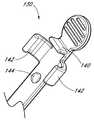
도 5a는 도 1a에 도시된 실시예의 가이드 와이어 섹션(28)의 사시도이다. 도 5b는 도 5a에 도시된, 가이드 와이어 허브(46)를 포함하는 것이 바람직한 가이드 와이어 섹션(28)의 평면도이다. 가이드 와이어 허브(46)는 의사 또는 의료인이 가이드 와이어 허브(46) 및/또는 접근 장치(20)를 용이하게 파지하거나 조작하도록 허용하는 하나 이상의 표면 형상부를 포함할 수 있다. 예시된 실시예에서, 가이드 와이어 허브(46)는 하나 이상의 릿지(110)를 포함한다. 선 장착된 상태에서, 가이드 와이어 허브(46)가 제3 위치[125; 예컨대, 도 6a에 예시된 제3 위치(125)]에 있을 때 가이드 와이어 허브(46)의 외부 표면은 트랙(30)의 로킹 기구(130)에 결합된다.FIG. 5A is a perspective view of the
일부 실시예에서, 가이드 와이어(44)는 후퇴시 자가 흡입 기능을 제공하도록 바늘 본체의 내경에 억지 끼움 맞춤을 형성할 수 있다. 예를 들면, 가이드 와이어(44)의 외경은 가이드 와이어의 길이를 따라 또는 가이드 와이어(44)의 일부만을 따라 바늘의 억지 끼움 맞춤을 형성하도록 선택될 수 있다.In some embodiments, the
일부 실시예에서, 가이드 와이어의 원위 단부는 가이드 와이어의 다른 섹션들과 비교하여 축소된 직경을 가질 수 있다. 이런 축소된 직경 섹션의 크기는 가이드 와이어가 바늘의 원위 팁을 지나 진행되었을 때도 유체가 바늘 본체의 천공부(56)를 통과할 수 있도록 선택될 수 있다.In some embodiments, the distal end of the guide wire may have a reduced diameter compared to other sections of the guide wire. The size of this reduced diameter section may be selected such that fluid can pass through the
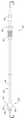
도 6a는 도 1a에 도시된 실시예의 트랙(30)의 사시도이다. 도 6b는 도 6a에 예시된 트랙(30)의 평면도이다. 도 6c는 도 6a에 예시된 트랙(30)의 측면도이다. 도 6a 내지 도 6c에 도시된 바와 같이, 예시된 실시예의 트랙(30)은 원위부(120)와, 근위부(122)와, 확장기 허브(38)에 트랙을 연결하는 원위 로킹 부재(124)와, 트랙(30)을 따라 제1 위치(121)로부터 제2 위치(123)로 바늘 허브(34)가 활주하면 바늘 허브(34)의 추가적 전후 이동을 방지하는 로킹 기구(128)와, 가이드 와이어 허브가 선 장착된 상태이거나 제3 위치(125)에 있을 때 가이드 와이어 허브(46)가 트랙(30)에 부착되는 것을 허용하는 로킹 기구(130)를 포함한다. 바람직하게는, 트랙은 폴리카보네이트 재료로 제조되지만, 이하 설명되는 바와 같이 다른 재료가 사용될 수 있다.FIG. 6A is a perspective view of the
트랙(30)은 도 6a 및 도 6b에 명확하게 도시된 바와 같이 축소된 폭을 갖는 트랙 섹션(132)을 더 포함할 수 있다. 축소된 폭은 트랙(30)에 바늘 허브의 조립을 용이하게 한다. 예시된 실시예는 트랙(30)의 원위부(120)에 리브(rib; 133)를 포함한다. 리브(133)는 원위 로킹 부재(124)와 트랙(30)의 나머지들 사이에 추가적 구조 강화를 제공한다.The
도 1a에 예시된 바와 같이, 원위 로킹 부재(124)는 확장기(24)에 연결되고 트랙(30)이 확장기(24)로부터 근위쪽 방향으로 연장되는 것을 허용한다. 예를 들면, 로킹 부재(124)는 확장기 허브의 립(77)과 확장기 허브의 베이스(79) 사이에 확장기 허브(38)를 연결하는 2개의 곡선형 아암(124)을 포함할 수 있다. 로킹 부재(124)는 확장기 허브(38)에 대해 원위쪽 또는 근위쪽 방향으로 트랙(30)의 이동을 제한하지만 확장기 허브(38) 주위에서 트랙(30)의 자유로운 회전을 허용한다.As illustrated in FIG. 1A, the
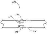
도 6d는 도 6b에 도시된 실시예의 일부를 확대한 확대도이다. 도시된 바와 같이, 로킹 기구(128)는 제2 위치(123)의 구역에서 트랙의 폭을 변경함으로써 형성된다. 예를 들면, 예시된 실시예는 원위쪽 방향으로 폭이 증가된 트랙 섹션(134)과, 폭이 증가된 트랙 섹션(134)의 원위부의 폭이 감소된 트랙 섹션(136)과, 2개의 핑거 요소(138)를 포함한다. 2개의 핑거 요소(138)는 트랙 섹션(136)의 원위 단부로부터 트랙(30)의 근위 단부 쪽으로 돌출되어 트랙(30)의 종축으로부터 멀어지는 방향으로 펼쳐져 있다.FIG. 6D is an enlarged view of a portion of the embodiment illustrated in FIG. 6B. As shown, the
도 6e는 도 6b에 도시된 실시예의 일부를 확대한 확대도이다. 로킹 기구(130)는 클립, 클레스프, 또는 가이드 허브가 제3 위치에 있을 때 트랙(30)의 일부 또는 가이드 와이어 허브의 일부와 결합되는 다른 구조부로 형성된다. 결합 구조부의 일부 또는 모두는 트랙(30)의 일부이거나, 가이드 와이어 허브의 일부이거나, 트랙(30)과 가이드 와이어 허브 사이의 틈(split)일 수 있다. 예시된 실시예에서, 로킹 기구(130)는 트랙(30)으로부터 연장되어 가이드 와이어 허브와 결합된다. 로킹 기구(130)는 트랙(30)으로부터 돌출된 직사각형 부재(140)와, 직사각형 부재(140)의 원위부에서 트랙(30)으로부터 돌출된 2개의 트랙 아암(142)과, 트랙 아암(142)의 원위부에서 트랙(30)으로부터 돌출된 정지부(144)를 포함한다.FIG. 6E is an enlarged view of a portion of the embodiment shown in FIG. 6B. The
예시된 실시예에서, 바늘 허브와 확장기 사이의 로킹 기구는 확장기 허브의 근위 측면에 위치된다. 그러나 다른 실시예에서, 로킹 기구는 다른 위치에도 배치될 수 있다. 예를 들면, 로킹 기구는 로킹 힌지에 의해 연결되는 2개의 피벗식 레버를 포함하며, 로킹 기구는 바늘 허브에 대해 반경 방향으로 배치될 수 있다. 이런 실시예에서, 하나의 레버는 확장기에 피벗식으로 커플링되고 다른 레버는 바늘에 피벗식으로 커플링된다. 바늘 허브가 확장기 허브로부터 멀어지는 방향으로 이동되면, 레버는 힌지가 로킹되는 지점과 일직선을 이룬다. 확장기에 대해 바늘 허브가 특정 지점을 지나 근위쪽으로의 이동을 제한하여 부재들을 함께 로킹하는 테더(tether)에 의해 유사한 효과가 도출될 수 있다. 다른 실시예에서, 세장형 구조는 확장기 내에서 바늘 허브로부터 바늘 본체에 평행하게 연장될 수 있다. 바늘 허브가 확장기로부터 충분히 먼 거리로 이동되면, 로킹 기구의 추가 구조[예컨대,디텐트(detent)]는 확장기에 대해 바늘의 추가 이동을 방지한다. 따라서, 이들 다른 실시예들에 예시된 바와 같이, 바늘과 확장기 사이에서 작동하는 로킹 기구는 확장기 허브에 대해 다양한 위치에 배치될 수 있다.In the illustrated embodiment, the locking mechanism between the needle hub and the dilator is located on the proximal side of the dilator hub. However, in other embodiments, the locking mechanism can also be arranged in other locations. For example, the locking mechanism includes two pivoting levers connected by a locking hinge, which locking mechanism can be arranged radially with respect to the needle hub. In this embodiment, one lever is pivotally coupled to the dilator and the other lever is pivotally coupled to the needle. When the needle hub is moved away from the dilator hub, the lever is in line with the point at which the hinge is locked. A similar effect can be produced by a tether that locks the members together by limiting the movement of the needle hub proximal to the point relative to the dilator. In other embodiments, the elongate structure may extend parallel from the needle hub to the needle body in the dilator. If the needle hub is moved far enough from the dilator, the additional structure of the locking mechanism (eg, detent) prevents further movement of the needle relative to the dilator. Thus, as illustrated in these other embodiments, the locking mechanism operating between the needle and the dilator may be placed at various positions relative to the dilator hub.
도 7a는 가이드 와이어가 선 장착된 도 1a에 도시된 실시예의 접근 장치의 확대 평면도이다. 도 7b는 도 7a에 도시된 실시예의 측면도이다. 도 7c는 도 7a에 도시된 라인(7C-7C)을 따라 취한 실시예의 단면도이다. 도 7d는 도 7a의 접근 장치(20)의 근위 단부 도면이다. 선 장착된 상태에서, 가이드 와이어 허브(46)는 가이드 와이어 허브(46)가 제3 위치(125)에 위치될 때 트랙(30)에 로킹된다. 이 위치에서, 가이드 와이어 허브(46)는 직사각형 부재(140)와 정지부(144) 사이의 트랙(30)에 고정될 수 있다. 예를 들면, 가이드 와이어 허브(46)는 직사각형 부재(140)와 정지부(144) 사이에서 해제 가능하게 로킹될 수 있다. 또한, 트랙 아암(142)은 가이드 와이어 허브(46)를 트랙(30)에 추가 고정할 수 있다. 이 로킹 기구는 가이드 와이어 허브(46)가 제3 위치(125)에 있을 때 적어도 원위 방향으로 가이드 와이어(44)의 의도되지 않은 회전 및 축 이동을 억제할 수 있다. 물론, 의료인은 접근 장치(20)를 통해 가이드 와이어의 원위 이동이 허용되도록 트랙(30)으로부터 가이드 와이어 허브(46)를 결합해제시킬 수 있다.7A is an enlarged plan view of the access device of the embodiment shown in FIG. 1A with the guide wire pre-mounted. FIG. 7B is a side view of the embodiment shown in FIG. 7A. FIG. 7C is a cross-sectional view of the embodiment taken along
도 7a 내지 도 7c에 도시된 사전 적하 상태(preloaded-state)에서, 바늘 허브(34)는 바늘 허브(34)가 제1 위치(121)에 있을 때 확장기 허브(38)에 로킹된다. 바람직하게는 로킹된 위치에서, 바늘과 확장기 내의 개방부 또는 천공부는 서로 등록되거나(in register) 정렬된다. 바늘(22)과 확장기(24)는 로킹될 때 서로에 대해 적어도 비의도적인 회전 및 축방향 이동이 억제된다. 바늘(34)에 대한 확장기 허브의 비의도적 회전을 방지함으로써 천공부 또는 개방부가 그들의 일반적 정렬을 유지한다.In the preloaded-state shown in FIGS. 7A-7C, the
사전 적하 상태에서, 확장기 허브(38)는 쉬스 허브(sheath hub: 42)에 고정된다. 이는 적어도 확장기(24)와 쉬스(26) 사이의 비의도적 회전 및 축방향 이동을 억제할 수 있다. 쉬스 허브(42)와 확장기(24)가 루어 슬립 연결부(luer slip connection)만 갖는 실시예에서 확장기(24)와 쉬스 허브(42)는 서로에 대해 회전할 수 있다.In the preloaded state, the
도 8a는 접근 장치(20)를 사용하는 하나의 방법의 작동 단계를 도시하는 도 1a에 도시된 실시예의 평면도이다. 도 8a는 정맥과 같은 혈관(148) 내로 삽입되는 접근 장치(20)의 바늘 본체(32)를 도시한다. 설명한 방법은 혈관 접근을 의미하지만, 접근 장치(20) 또한 환자의 몸 내부의 다른 위치 내로 카테터 또는 쉬스를 접근시키고 위치시키는 데 사용될 수 있고(예를 들어, 농양 배출), 다른 목적을 위해서도 사용될 수 있다.FIG. 8A is a top view of the embodiment shown in FIG. 1A showing the operational steps of one method using the
도 8b는 선 8b-8b에 의해 동그라미 쳐진 도 8a에 도시된 실시예의 부분의 확대 평면도이다. 도 8c는 선 8c-8c에 의해 동그라미 쳐진 도 8b에 도시된 실시예의 부분의 확대 평면도이다. 도 8d는 선 8d-8d를 따른 도 8c에 도시된 실시예의 확대 단면도이다.8B is an enlarged plan view of a portion of the embodiment shown in FIG. 8A circled by lines 8b-8b. 8C is an enlarged plan view of a portion of the embodiment shown in FIG. 8B circled by lines 8c-8c. 8D is an enlarged cross-sectional view of the embodiment shown in FIG. 8C along line 8d-8d.
위에서 언급한 바와 같이, 바늘 본체(32)는 그의 측벽 내에 하나 이상의 측부 개방부(56)를 포함한다. 확장기 샤프트(36)는 하나 이상의 측부 개방부(74)를 포함한다. 측부 개방부(56, 74)는 가로세로비 뿐 아니라 형상도 동일하거나 상이할 수 있다. 도시된 실시예에서 바늘 본체(32) 내의 측부 개방부(56)는 확장기 샤프트(36) 내의 측부 개방부(74)와 상이한 가로세로비를 갖는다. 바늘 본체(32) 내의 측부 개방부(56)는 일 방향으로[예를 들어, 바늘 본체(32)의 종방향 축에 실질적으로 평행하게] 연장된다. 확장기 샤프트(36) 내의 측부 개방부(74)는 상이한 방향으로[예를 들어, 확장기 샤프트(36)의 주연을 따라] 연장된다. 바늘 본체(32)와 확장기 샤프트(36) 내에 오프셋된 세장형 개방부(56, 74)를 가짐으로써, 바늘 측부 개방부(56)와 확장기 측부 개방부(74)를 통해 혈액이 유동하도록 바늘 본체(32)와 확장기 샤프트(36) 내의 개방부(56, 74)가 충분히 정렬될 수 있는 가능성을 증가시킨다. 도 8a 내지 도 8d는 한 세트의 대응하는 측부 개방부들 사이의 정렬을 도시한다. 또한, 다른 세트의 측부 개방부는 바늘 본체(32)와 확장기 샤프트(36)의 상대적 배향에 따라 정렬되거나 오정렬될 수 있다.As mentioned above, the
도시된 실시예에서 확장기 샤프트(36)는 바늘 본체(32)와 확장기 샤프트(36) 사이의 환형 공간(150)을 최소화시키도록 동축으로 위치된다. 확장기 샤프트(36)의 내부 표면(152)은 비록 그러 수 있다고 하더라도 바늘 본체(32)의 외부 표면(154)에 대해 직접적으로 놓일 필요가 없다. 바람직하게는, 이러한 실시예에서, 바늘 본체(32)의 외부 표면(154)과 확장기 샤프트(36)의 내부 표면(152) 사이의 환형 공간(150)은, 확장기 샤프트(36)와 바늘 본체(32) 사이의 환형 공간(150) 내로의 혈액이나 그의 성분(또는 다른 체액)의 유동을 억제하기 위해 최소화된다. 유리하게는, 이러한 특징은 복수의 오부 표면에 혈액이 노출되는 것을 최소화시키고, 오염, 감염, 및 응고의 위험을 감소시킨다.In the illustrated embodiment, the
도 8a에 도시된 바와 같이, 확장기 샤프트(36)는, 바늘 본체(32) 상에 배치된 한 측부 개방부(56)의 적어도 부분이 확장기 샤프트(36) 상의 한 측부 개방부(74)의 적어도 부분과 회전식으로 정렬되도록 바늘 본체(32)에 동축으로 장착된다. 바람직하게는, 바늘 본체(32)와 확장기 샤프트(36)는 혈액이 바늘 측부 개방부(56)와 확장기 측부 개방부(74)를 통해 유동하도록 회전식 정렬을 유지한다.As shown in FIG. 8A, the
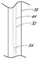
앞서 언급한 바와 같이, 쉬스 본체(40)는 바람직하게는 깨끗하고, 반 불투명(semi-opaque), 아투명(translucent), 또는 투명한(transparent) 재료로부터 부분적으로 또는 전부 만들어져서, 혈액이 바늘 본체(32) 내로 유동할 때, 즉 (1) 바늘 측부 개방부(56)를 통과하고, (2) 확장기 측부 개방부(74)를 통과하고, (3) 채널(156) 내로 유동할 때 의사 또는 의료인은 혈액을 볼 수 있다. 일부 모드에서, 채널(156)은 확장기 샤프트(36)와 쉬스 본체(40) 사이에 형성되고, 확장기 샤프트(36) 상의 하나 이상의 릿지(76)에 의해 한정된다. 일부 모드에서, 바람직하게는 확장기 샤프트(36)가 투명한 재료를 포함하고 채널(156)이 확장기 샤프트(36)의 벽 내부에 형성된다. 혈액은 바늘 본체(32)의 경사 팁(54)이 혈관(148)을 찔렀다는 것을 의사나 의료인에게 나타낼 것이다.As mentioned above, the
일부 실시예에서, 바늘 본체(32)와 확장기 샤프트(36)(둘 다)는 이러한 측부 개방부들 중 일부 또는 모두가 회전식으로 정렬될 수 있는 다수의 측부 개방부를 가질 수 있다.In some embodiments, the
채널(156)은 쉬스(26)의 길이와 거의 같은 공간에 걸치는 축방향 길이를 가질 수 있다. 다른 실시예에서, 채널(156)은 방금 설명된 세장형 채널(156)보다 현저하게 작을 수 있다. 예를 들어, 채널(156)은 쉬스(26)의 원위의 중간 및/또는 선단 부분 내부에 배치될 수 있으나, 이에 제한되지 않는다. 채널(156)은 쉬스(26)의 축방향 길이를 따라 선형이거나 만곡되거나 또는 나선형인 형상을 가질 수 있으며, 또는 복수의 이러한 형상들에 의해 형성될 수 있다. 채널(156)은 다양한 두께와 스팬 각도(span angle)를 가질 수 있다. 채널(156)의 두께는 거의 제로에 가까운 것으로부터 0.254 mm(0.010 인치)까지의 범위에 있을 수 있다. 바람직하게는, 채널(156)은 약 0.0127 mm(0.0005 인치) 내지 약 0.0762 mm(0.003 인치)의 두께를 갖는다. 더 바람직하게는, 채널(156)은 약 0.0254 mm(0.001 인치) 내지 약 0.0508 mm(0.002 인치)의 두께를 가질 수 있다. 채널(156)은 확장기(24)의 축에 대해 약 30도 내지 약 210도 또는 그 이상, 그러나 바람직하게는 360도 미만의 스팬 각도(Φ)를 가질 수 있다. 더 바람직하게는, 채널(156)은 약 60 내지 150의 스팬 각도(Φ)를 가질 수 있다. 도시된 실시예에서, 채널(156)은 120도로 스팬된다(span). 두께와 스팬 각도(Φ)는, 유체(예를 들어, 전혈)가 채널(156)로 유입될 때 채널(156) 내부에 발생하는 모세관 현상을 최적화하도록 선택될 수 있으며, 또한 체강 내의 예상되는 압력과 액체의 점성도에 기초하여 선택될 수 있다.
도 8e 내지 도 8g는 스팬 각도가 120도일 때 유체가 얼마나 빨리 채널(156)의 표면에서 인출(draw up)되는지 도시하는 시험 데이터의 그래프이며, 접촉 각도(θ)는 5도이고, 주연 길이(H)는 60도에서 0.64 mm이다. 각 그래프 상에서 충전(filling) 길이(mm)는 y축 상에 플로팅되고, 시간(초)은 x축 상에 플로팅된다. 시험은 주변 혈관 내에서 경험되는 압력과 유사한 유체역학적 압력에서 실행되었다. 도 8e는 비율 유체(rate fluid)가 0.0508 mm(0.002 인치)의 간극 높이 폭을 갖는 채널(156)에서 인출되는 것을 도시하고, 도 8f는 비율 유체가 0.0254 mm(0.001 인치)의 간극 높이 폭을 갖는 채널(156)에서 인출되는 것을 도시하며, 도 8g는 비율 유체가 0.0127 mm(0.0005 인치)의 간극 높이 폭을 갖는 채널(156)에서 인출되는 것을 도시한다. 도 8e 내지 도 8g에 도시된 바와 같이, 유체는 0.0127 mm(0.0005 인치)의 간극 높이 폭을 갖는 채널 내에서 가장 빠르게 인출되고, 0.0254 mm(0.001 인치)의 간극 높이 폭을 갖는 채널이 그 뒤를 잇고, 0.0508 mm(0.002 인치)의 간극 높이 폭을 갖는 채널이 그 뒤를 잇는다.8E-8G are graphs of test data showing how quickly fluid is drawn up from the surface of
전술한 채널(156)의 형상과 그에 따른 모세관 현상은, 전혈과 상이한 점성도를 갖는 다른 유체[예를 들어, 백혈구, 고름(pus), 소변, 혈장]와 대조하여 전혈로 사용하는 데 최적화되었다. 그러나, 채널(156)의 형상은 기재된 형상에 제한되지 않고, 고름과 같은 다른 액체를 배출하는 데 최적화될 수 있다. 또한, 전술한 채널(156)의 형상은, 혈관 내의 압력이 모세관 현상과 그에 따른 혈액 플래쉬(blood flash)를 향상시키는 주연으로 위치된 혈관을 위해서 뿐 아니라 압력이 낮을 수 있는 영역 내에 위치한 혈관을 위해서도 최적화되었다. 예를 들어, 몸의 흉강(thorax) 영역에서, 정맥 내의 예상된 압력은 환자가 호흡할 때 주연으로 위치된 정맥 내에서보다 낮을 수 있다. 몸의 다른 영역 내의 접근 장치(20)의 사용을 위한 채널의 상이한 크기는 혈관 또는 체강 내부의 예상된 압력을 고려하여 채용될 수 있다.The shape of the
또한, 확장기 샤프트(36)의 외부 표면(160) 및/또는 쉬스 본체(40)의 내부 표면(158)은 채널(156) 내부의 모세관 현상을 조장하거나 향상시키기 위해 일정 물질로 코팅될 수 있다. 예를 들어, 모세관 현상을 향상시키기 위해 확장기 샤프트(36)의 외부 표면(160) 및/또는 쉬스 본체(40)의 내부 표면(158)을 코팅하는 데 친수성 물질이 사용될 수 있다. 다른 예시로서, 이러한 표면들을 코팅하는 데 계면활성제가 사용될 수 있다. 코팅될 수 있는 다른 표면은, 바늘(22)의 내부 표면, 바늘(22)의 외부 표면, 가이드 와이어(44)를 포함한다. 일부 실시예에서, 계면활성제는 일부 계면활성제가 확장기(및/또는 바늘) 내의 천공부를 통과하도록 적용될 수 있다. 다른 실시예에서, 하나 이상의 구성요소는 친수성 재료로 만들어질 수 있다. 환자 내로 쉬스(26)의 삽입을 쉽게 하기 위해 윤활제로서 작용하도록 친수성 물질이 부가적으로 쉬스(26)의 외부 표면에 적용될 수 있다. 쉬스(26)의 외부 상에 다른 윤활제 또는 윤활성 코팅이 사용될 수 있으며, 또는 적어도 쉬스의 외부 표면은 윤활성 재료로 형성될 수 있다. 또한, 쉬스(26)는 접근 장치(20)의 의료적 응용을 용이하게 하기 위해, 쉬스로부터 용리되는(elute) 작용제(예를 들어, 헤파린)와 함께 코팅되거나 형성될 수 있다.In addition, the
도 8h는 선 8h-8h를 따른 도 8c에 도시된 실시예의 단면도이다. 도시된 접근 장치(20)의 이러한 영역 내에서, 쉬스 본체(40)는 여전히 쉬스 본체(40)와 확장기 샤프트(36)의 상대적 이동을 허용하면서 쉬스 본체(40)와 확장기 샤프트(36) 사이의 환형 공간(157)을 최소화시키도록 동축으로 위치된다. 쉬스 본체(40)의 내부 표면(158)은 비록 그럴 수 있다고 하더라도 확장기 샤프트(36)의 외부 표면(160)에 대해 직접적으로 놓일 필요가 없다. 확장기 샤프트(36) 내의 개방부(74)로부터의 혈액이나 혈액의 성분(또는 다른 체액)의 원위 유동을 억제하기 위해, 확장기 샤프트(36)의 외부 표면(160)과 쉬스 본체(40)의 내부 표면(158) 사이의 환형 계면(157)은 이러한 영역에서 감소될 수 있다.8H is a cross-sectional view of the embodiment shown in FIG. 8C along line 8h-8h. Within this region of the illustrated
도 8i는 선 8i-8i에 의해 동그라미 쳐진 도 8a에 도시된 실시예의 부분의 확대 평면도이다. 도 8j는 도 8i에 도시된 실시예의 단면도이다. 도 8i 및 도 8j는 바늘 허브가 제1 위치(121) 내에 있을 때 확장기 허브(38)에 로킹된 바늘 허브(34)를 도시한다. 확장기 샤프트(36)는, 확장기 샤프트(36)의 중공 섹션(84)을 바늘 본체(32) 위로 슬립핑시키고 확장기 허브(38)를 바늘 허브(34)에 해제가능하게 고정시킴으로써 바늘 본체(32)에 동축으로 장착될 수 있다. 확장기 허브(38)의 선단부(86)는 바늘 허브(34)와 기계적으로 끼워지고 상호로킹되도록 구성된다.8I is an enlarged plan view of a portion of the embodiment shown in FIG. 8A circled by lines 8i-8i. 8J is a cross-sectional view of the embodiment shown in FIG. 8I. 8I and 8J show the
확장기 샤프트(36)는 확장기 샤프트(36)가 바늘 본체(32)에 대해 동축 위치로부터 장착되고 해제되거나 그와 반대일 수 있도록 바늘 본체(32)에 해제가능하게 장착될 수 있다. 이러한 로킹 구조는 바늘 허브(34)가 제1 위치 내에 있을 때 적어도 바늘(22)과 확장기(24) 사이의 일부 비의도적 회전 및 축방향 이동을 억제할 수 있다. 도시된 바와 같이, 바늘 허브(34)는 확장기 허브(38)의 루어 연결부(78)에 로킹된 루어 연결부(64)를 가질 수 있다. 또한, 바늘 허브(34)는 또한 확장기 허브(38) 내의 개방부(82)에 로킹되는 래치 요소(66)를 가질 수 있다.The
또한, 도 8i 및 도 8j는 접근 장치(20)가 혈관(148) 안으로 삽입될 때 쉬스 허브(42)와 결합하는 확장기 허브(38)를 도시한다. 바람직하게는, 쉬스 허브(42)의 근위 단부(86)는 확장기 허브(38)에 기계적으로 끼워지고 해제 가능하게 결합되도록 구성된다. 도시된 바와 같이, 확장기 허브(38)의 루어 연결부(80)는 쉬스 허브의 로킹 부재(94)와 결합된다. 이렇게 발생된 마찰 끼움은 접근 장치(20)가 혈관(148) 내에 삽입될 때 확장기(24)와 쉬스(26) 사이의 의도하지 않은 회전 및 축방향 이동을 적어도 일부 방지할 수 있다.8I and 8J also show the
도 9a는 접근 장치(20)의 추가적인 작동 단계를 도시하는, 도 1a에 도시된 실시예의 측면도이다. 도 9a는 혈관(148)을 향해 원위 방향으로 전진된 접근 장치(20)의 가이드 와이어(44)를 도시한다. 이것은 가이드 와이어 허브(46)를 제3 위치(125)로부터 원위 방향으로 전진시킴으로써 달성될 수 있다. 그 후 가이드 와이어 허브(46)는 바늘 허브(34)가 제1 위치(121)에 있을 때 바늘 허브(34)에 로킹된다.9A is a side view of the embodiment shown in FIG. 1A, showing further operational steps of the
도 9b는 선 9B-9B에 의한 원 내에 있는 도 9a에 도시된 실시예의 일부를 확대한 측면도이다. 도 9c는 도 9b에 도시된 실시예의 단면도이다. 도 9c는 가이드 와이어 허브(46)와 바늘 허브(34) 사이의 로킹 기구를 도시한다. 바람직하게는, 가이드 와이어 허브(46)는 바늘 허브(34)에 기계적으로 끼워지고, 해제 가능하게 또는 비가역적으로 맞물리도록 구성된다. 도시된 바와 같이, 가이드 와이어 허브(46)는 가이드 와이어 허브(46)의 내측 표면 상에 너브(162, nub)를 포함한다. 가이드 와이어 허브의 너브(162)는 너브(162)가 바늘 허브(46)의 립 상의 나사형 홈 내에 고정될 때까지 가이드 와이어 허브(46)를 원위 방향으로 전진시킴으로써 바늘 허브(34) 상에 로킹될 수 있다. 다른 실시예에서, 가이드 와이어 허브(46)는 대응하는 나사 요소를 통해 바늘 허브(34)에 로킹될 수 있다.9B is an enlarged side view of a portion of the embodiment shown in FIG. 9A in a circle by
도 10a는 접근 장치(20)의 다른 작동 단계를 도시하는, 도 1a에 도시된 실시예의 측면도이다. 도 10a는 혈관(148)을 향해 원위 방향으로 전진된 쉬스 본체(40) 및 확장기 샤프트(36)를 도시한다. 이것은 확장기 허브(38)를 바늘 허브(34)로부터 해제하고 확장기(24) 및 쉬스(26)를 가이드 와이어 및 바늘을 따라 바늘 허브(34)에 대해 상대적으로 원위 방향으로 전진시킴으로써 달성될 수 있다. 도 10a는 확장기(24) 및 쉬스(26)에 대해 상대적인 바늘(22) 및 가이드 와이어 섹션(28)의 근위방향 이동을 더 도시한다. 바늘 허브(34)는 바늘 허브(36)가 제2 위치(123)에 도달할 때 트랙(30)에 로킹될 것이다.10A is a side view of the embodiment shown in FIG. 1A, showing another stage of operation of the
도 10b는 선 10B-10B에 의한 원 내에 있는 도 10a에 도시된 실시예의 일부를 확대한 배면도이다. 도 10b에 도시된 바와 같이, 바늘 허브(34)는 제2 위치(123)에 있는 로킹 기구(128)를 통해 트랙(30) 상에 로킹된다. 바늘 허브 탱(68)은 트랙 핑거(138) 위에서 근위 방향으로 활주하며, 상기 탱(68)은 트랙 핑거(138)와 증가하는 폭(134)의 트랙 섹션 사이의 위치로 로킹될 수 있다. 이것은 바늘 허브(34)가 제2 위치(123)에 있을 때 적어도 원위 방향으로 바늘 본체(32)의 축방향 이동을 구속하고, 더 바람직하게는 실질적으로 불가역적으로 방지한다. 도시된 실시예에서, 로킹 기구(128)는 일단 결합되면 바늘 허브(34)가 근위 또는 원위 방향으로 이동하는 것을 불가역적으로 방지한다. 또한, 바늘(22)의 원위 팁(54)은 바늘 허브(34)가 제2 위치(123)에 있을 때 원위 팁(54)을 피복하도록 확장기(24) 안으로 끌려온다. 따라서, 일단 확장기 샤프트(36)가 사용 동안 바늘 본체(32) 위에서 전진되면, 로킹 기구(128)는 바늘 본체(32)의 원위 단부(50) 상에 배치된 경사 팁(54)이 확장기 샤프트(36)의 원위 단부 너머로 전진되는 것을 방지한다. 따라서, 확장기 샤프트(36)는 바늘 본체(32)의 예리한 경사 팁(54)을 피복하여 불의의 바늘 찔림이 발생하는 것을 방지한다.FIG. 10B is an enlarged rear view of a portion of the embodiment shown in FIG. 10A in a circle by
도 11a는 접근 장치(20)의 최종 작업 단계를 도시하는, 도 1a에 도시된 실시예의 측면도이다. 도 11a는 혈관(148) 내에 적절히 삽입된 쉬스 본체(40)를 남긴 채 혈관으로부터 가이드 와이어(44) 및 확장기 샤프트(36)를 제거하는 것을 도시 한다. 도 11b는 선 11B-11B에 의한 원 내에 있는 도 11a에 도시된 실시예의 일부의 확대된 평면도이다. 도 11b로부터 확실히 알 수 있는 바와 같이, 확장기 샤프트(36)의 원위 단부 및 가이드 와이어(44)는 바늘 본체(32)의 예리한 경사 팁(54) 너머로 연장되어 불의의 바늘 찔림을 방지한다.11A is a side view of the embodiment shown in FIG. 1A, showing the final working stage of the
상술한 바와 같이, 바늘 본체(32)와 확장기 샤프트(36)의 개구(56, 74)들이 상이한 종횡비를 가짐으로써 바늘측 개구(56) 및 확장기측 개구(74)를 통한 혈액 유동이 방해받지 않도록 바늘 본체(32) 및 확장기 샤프트(36)의 개구(56, 74)들이 정렬될 가능성이 증가할 것이다.As described above, the
다음의 실시예들에서, 실시예들 간에 유사한 구조체는 동일한 기본 도면 부호를 공유하고, 각각의 실시예는 특유의 접미 문자를 포함한다(32, 32A, 32B 등). 도 12a는 도 8b 및 도 8c에 도시된 바늘 본체(32) 및 확장기 샤프트(36)의 개구(56, 74)의 다른 실시예의 평면도이다. 도 12b는 선 12B-12B를 따라 취한, 도 12a에 도시된 실시에의 확대 단면도이다. 도 12a 및 도 12b는 타원형 개구(56A)를 갖는 바늘 본체(32A) 및 원형 개구(74A)를 갖는 확장기 샤프트(36A)를 도시한다. 다른 실시예에서, 바늘은 원형 개구를 가질 수 있고, 확장기는 타원형 개구를 가질 수 있다. 이들 실시예는 혈액이 바늘측 개구(56A) 및 확장기측 개구(74A)를 통해 유동하도록 개구(56A, 74A)들이 적어도 실질적으로 정렬될 가능성을 증가시킬 수 있다.In the following embodiments, similar structures among the embodiments share the same basic reference numerals, and each embodiment includes a unique suffix (32, 32A, 32B, etc.). 12A is a plan view of another embodiment of the
도 13a는 도 8b 및 도 8c에 도시된 바늘 본체(32) 및 확장기 샤프트(36)의 개구(56, 74)의 다른 실시예의 평면도이다. 도 13b는 선 13B-13B를 따라 취한, 도 13a에 도시된 실시예의 확대 단면도이다. 도 13a 및 도 13b는 원형 개구(56B)를 가진 바늘 본체(32B) 및 바늘 본체(32B)의 원형 개구(56B)보다 큰 원형 개구(74B)를 가진 확장기 샤프트(36B)를 도시한다. 다른 실시예에서, 확장기의 개구는 바늘의 개구보다 작을 수 있다. 이들 실시예는 또한 혈액이 바늘측 개구(56B) 및 확장기측 개구(74B)를 통해 유동하도록 개구(56B, 74B)들이 적어도 실질적으로 정렬될 가능성을 증가시킬 수 있다.13A is a plan view of another embodiment of the
상술한 바와 같이, 확장기 샤프트(36)는 내과의 또는 의료 행위자가 바늘 본체(32)의 경사 팁(54)이 혈관에 적절히 구멍을 낸 후에 혈액을 보는 것을 가능하게 하기 위해 쉬스 본체(40)와 확장기 샤프트(36) 사이에 도관 또는 유동로를 형성하도록 릿지(76)들 사이에 형성되는 하나 이상의 채널(156)을 가질 수 있거나, 또는 채널은 다양한 가능한 구성의 축방향 만입부를 압출함으로써 또는 확장기 샤프트 또는 본체 내에 완전히 둘러싸인 채널을 형성함으로써 릿지 없이 형성될 수 있다.As noted above, the
도 14a는 도 8c에 도시된 릿지(76)의 다른 실시예의 평면도이다. 도 14b는 도 8d에 도시된 릿지(76)의 다른 실시예의 확대 단면도이다. 도 14a 및 도 14b는 쉬스 본체(40C)와 확장기 샤프트(36C) 사이에 적어도 하나의 채널(156C)을 형성하는 쉬스 본체(40C)의 내측 표면(158C) 상에 있는 2개의 릿지(76C)를 도시한다.14A is a top view of another embodiment of the
도 15a는 도 8c에 도시된 릿지(76)의 다른 실시예의 평면도이다. 도 15b는 도 8d에 도시된 릿지(76)의 다른 실시예의 확대 단면도이다. 도 15a 및 도 15b는 쉬스 본체(40D)와 확장기 샤프트(36D) 사이에 채널(156D)을 형성하기 위해 합체되는 확장기 샤프트(36D)의 외부 표면(160D)상의 2개의 릿지(76E) 및 쉬스 본체(40D)의 내부 표면(158D)상의 2개의 릿지(76D)를 도시한다. 예를 들어, 소정의 채널 두께가 약 0.0254 mm (0.001 인치)인 경우, 쉬스 본체(40D)의 내부 표면(158D)상의 2개의 릿지(76D)는 각각 약 0.0127 mm (0.0005 인치) 두께일 수 있으며 확장기 샤프트(36D)의 외부 표면(160D)상의 2개의 릿지(76E)는 각각 약 0.0127 mm (0.0005 인치) 두께일 수 있다.FIG. 15A is a top view of another embodiment of the
도 16a는 도 8c에 도시된 릿지(76)의 다른 실시예의 평면도이다. 도 16b는 8d에 도시된 릿지(76)의 다른 실시예의 확대 단면도이다. 도 16a 및 도 16b는 확장기 샤프트(36E)의 외부 표면(160E)상의 많은 릿지를 도시한다. 인접한 릿지들 사이에는 돌출부(76F)(spline)가 있다. 돌출부(76F)는 쉬스 본체(40E)와 확장기 샤프트(36E) 사이에 복수의 채널(156E)을 형성한다. 하나 이상의 채널(156E)은 동일한 스팬 각도(φ) 또는 상이한 스팬 각도(φ)를 가질 수 있다. 도시된 실시예에서, 채널(156E)은 120° 및 23°의 스팬 각도를 갖는다. 다른 실시예에서, 단일 릿지(76)는 확장기의 외부 주위에서 그 길이를 따라 감길 수 있다.16A is a top view of another embodiment of the
도 17은 접근 장치의 다른 실시예의 확대 단면도이며 의료 제품 또는 쉬스 본체(40F)와 상이한 형상을 갖는 확장기 샤프트(36F) 사이에 형성된 채널(156F)을 도시한다. 도시된 실시예에서, 확장기 샤프트(36F)의 외부 표면은 타원형인 반면 쉬스 본체(40F)의 내부 표면은 라운드형이다. 타원형 확장기 샤프트(36F) 및 인접한 라운드형 쉬스 본체(40F)는 확장기 샤프트(36F)와 쉬스 본체(40F) 사이에 하나 이상의 채널 또는 갭(156F)을 형성한다. 물론, 쉬스 본체(40F)와 확장기 샤프트(36F)의 형상은 라운드형과 타원형으로 제한되지 않으며 쉬스 본체(40F)와 확장기 샤프트(36F)의 인접 영역들의 상이한 형상의 임의의 다른 조합을 포함할 수 있다. 몇몇 모드의 경우, 확장기 샤프트(36F)의 외부 표면은 길쭉하고(oblong) 쉬스 본체 또는 의료 제품(40F)의 내부 표면은 라운드형이다. 몇몇 모드의 경우, 확장기 샤프트(36F)의 외부 표면은 라운드형이며 의료 제품(40F)의 내부 표면은 정방형이다. 갭 또는 채널(156F)은 종축, 종축을 따르는 나선 경로, 종축을 따르는 선형 경로, 또는 접근 장치를 따르는 다른 경로를 따를 수 있다. 몇몇 모드의 경우, 선형 경로는 종축에 평행하다. 갭 또는 채널(156F) 두께는 갭 또는 채널(156F)의 길이의 적어도 일부를 따라 변할 수 있다.FIG. 17 is an enlarged cross-sectional view of another embodiment of the access device and shows a
다른 실시예에서, 채널(156)은 쉬스의 내부 표면상에 하나의 완전한 릿지와 확장기의 외부 표면상에 하나의 완전한 릿지를 가짐으로써 형성될 수 있다. 다른 실시예에서, 쉬스의 내부 표면은 채널(156)의 길이의 50%를 차지하는 2개의 릿지를 가질 수 있으며 확장기의 외부 표면은 채널(156)의 나머지 50%를 차지하는 2개의 릿지를 가질 수 있다.In another embodiment, the
도 18 및 도 19는 바늘(22')의 추가 실시예를 도시한다. 바늘(22')은 원위 팁에서 에코 부분(240)(echogenic portion)을 포함할 수 있다. 에코 부분은 화상형성(imaging)에 사용되는 파를 산란하는 재료를 포함할 수 있고, 이로써 초음파하에서 바늘의 시각화를 촉진한다. X 선 또는 형광 투시법하에서 시각화를 촉진하는 무선-불투명부(radio-opaque portion)를 갖는 바늘을 사용하는 것과 같은 다른 화상형성 기술이 사용될 수도 있다. 에코음영(echogenicity)은 표면을 거칠게 하기 위해 상기 부분(240)을 샌드 블라스팅(sandblasting)함으로써 증가될 수 있다. 팁은 샌드 블라스팅 후에 첨예화(sharpened)될 수 있어서, 바늘의 팁이 에코성(echogenic)이 될 수 있다. 에코음영은 과립 불순물(granular impurity)을 첨가하는 것과 같은 바늘 자체의 내부 재료를 변경함으로써 증가될 수도 있다. 그러나, 몇몇 예에서, 내부 재료의 변경은 바늘의 구조적 일체성과 타협하지 못할 수 있다. 유리하게, 에코음영 또는 유사한 화상형성 적합성은 조작자가 초음파와 같은 스캐닝 기술을 사용하여 신체 내부에서 바늘 팁을 쉽게 볼 수 있도록 할 수 있다.18 and 19 show a further embodiment of the needle 22 '. The
몇몇 실시예에서, 에코 부분(240)을 구비한 바늘은 천공부(56, 74), 그루브(75), 및/또는 계면활성제를 포함하지 않을 수 있다. 또한, 에코 부분(240)을 구비한 몇몇 예에서, 접근 장치는 플래쉬백 공간 또는 플래쉬 챔버를 포함하지 않을 수 있다.In some embodiments, the needle with
다른 실시예에서, 바늘(22')은 (전술한 다른 임의적 특징 이외에) 에코 부분(240) 및 천공부(56) 모두를 가질 수 있다. 또한, 다른 실시예에서, 바늘(22')은 대조 부분(250)을 포함할 수 있다. 대조 부분(250)은 대조 부분을 둘러싸는 유체의 가시성을 개선하는 광학 특성을 가질 수 있다. 예를 들어, 전술한 바와 같이, 몇몇 실시예에서, 체액은 천공부(56)를 통해 플래쉬백 공간으로 유동할 수 있다. 그때, 대조 부분(250)은 플래쉬백 공간에 일반적으로 인접하여 배치될 수 있으며, 대조 부분은 체액과 대조되는 광학 특성을 가질 수 있다. 따라서, 플래쉬백 공간으로의 체액의 유입은 더욱 즉각적으로 더욱 분명해질 수 있다.In other embodiments, the
예를 들어, 플래쉬백 공간으로 유입하는 유체가 혈액과 같은 체액인 경우, 대조 부분(250)은 백색, 녹색, 청색 등과 같은, 혈액의 색상과 대조되는 색상을 가질 수 있다. 추가 실시예에서, 다른 광학 특성은 반사성 또는 무광 마무리 사이에서 선택하는 것 등으로 변화할 수 있다. 다른 실시예에서, 대조 부분(250)은 줄무늬, 격자형, 점무늬, 또는 광학 특성이 변화하는 몇몇 다른 패턴을 가질 수 있다. 예를 들어, 대조 부분(250)은 바늘을 따라 축방향 및/또는 둘레방향으로 배향된 흑색 및 백색 줄무늬를 가질 수 있다. 상이한 광학 특성을 동반한 패턴이 활용되는 경우, 대조 부분(250)은 대조 부분(250)의 하나의 영역으로부터는 구별가능하지만 다른 영역과는 구별되지 않을 수 있는 상이한 유체로 더욱 포괄적일 수 있다.For example, when the fluid entering the flashback space is a body fluid such as blood, the
변화하는 광학 특성은 다양한 방법으로 적용될 수 있다. 예를 들어, 몇몇 실시예에서, 대조 부분(250)은 특정 색상, 마감, 패턴 등을 갖도록 도색될 수 있다. 다른 실시예에서, 바늘의 부분은 대조 부분(250)의 반사 특성에 영향을 주도록 광택처리 또는 조도처리(roughened)될 수 있다. 추가 실시예에서, 대조 부분(250)은 상이한 광학 특성을 얻기 위해 상이한 소재로 형성되거나, 또는 그 표면에 적용되는 상이한 재료를 가질 수 있다. 심지어, 몇몇 실시예에서, 대조 부분(250)은 전술한 에코 부분(240)에서와 같이 에코성으로 이루어질 수 있다.Changing optical properties can be applied in a variety of ways. For example, in some embodiments,
도 18에 도시된 바와 같이, 대조 부분(250)은 천공부(56)로부터 바로 근위측에 위치될 수 있고 바늘(22')의 전체 거리보다 작은 거리로 연장할 수 있다. 이러한 위치는 일반적으로 천공부(56)의 바로 근위측에 있을 수 있는 플래쉬백 공간의 초반에 대응한다. 그러나, 다른 실시예에서, 플래쉬백 공간 및 대조 부분(250) 중 하나 또는 양자 모두의 위치는 변할 수 있다. 예를 들어, 몇몇 실시예에서, 대조 부분(250)은 천공부(56)를 가로질러 스팬(span)할 수 있거나, 또는 그로부터 일정 거리 이격될 수 있다. 추가 실시예에서, 대조 부분(250)은 바늘 허브로 연장할 수 있거나, 또는 바늘 본체 전체를 스팬할 수 있다. 도시된 바와 같이, 대조 부분(250)은 바늘 전체 주위에서 둘레방향으로 스팬할 수 있다. 그러나, 몇몇 실시예에서, 대조 부분(250)은 천공부(56)의 각도 스팬에 대응하는 각도 스팬을 갖는 각도 부분과 같이, 바늘 본체의 각도적으로 축소된 부분을 따라서만 위치될 수 있다.As shown in FIG. 18, the
(전술한 바와 같이) 플래쉬백 공간이 확장기와 쉬스 사이에 발생하는 실시예에서, 확장기는 클리어, 아투명, 또는 반투명한 대응 부분을 가짐으로써, 대조 부분(250)은 접근 장치의 외부로부터 보일 수 있다. 그러면, 체액과 같은 유체가 플래쉬백 공간으로 유입될 때, 플래쉬백 공간으로 유입하는 체액이 대조 부분(250)을 가리기 때문에, 관찰자는 대조 부분(250)과 체액을 모두 볼 수 있다. 그러면, 유체와 대조 부분(250) 사이의 광학 특성의 대조는 유체의 유입의 시각적 감지를 촉진할 수 있다.In embodiments where a flashback space occurs between the expander and the sheath (as described above), the expander has a clear, transparent or translucent counterpart, such that the
이러한 개념은 다른 실시예에도 적용될 수 있다. 예를 들어, 몇몇 실시예에서, 플래쉬백 공간은 바늘과 확장기 사이에 제공될 수 있다. 전술한 바와 같이, 바늘 천공부(56)를 통해 혈액이나 다른 유체를 수용할 수 있는, 확장기와 쉬스 사이의 채널은 바늘과 확장기 사이에 형성될 수 있다. 이러한 플래쉬 공간의 예는 2009년 3월 13일자로 출원되어 그 전체가 본원에 참조로 통합된 출원번호 PCT/US2009/037204의 도 18b 내지 도 18d 및 첨부된 명세서에 설명된다.This concept can be applied to other embodiments. For example, in some embodiments, a flashback space may be provided between the needle and the dilator. As noted above, a channel between the dilator and the sheath, which can receive blood or other fluid through the
따라서, 몇몇 실시예에서, 사전 조립식 접근 장치에는 가이드 와이어, 확장기, 쉬스, 및 관련 허브와 함께, 어떠한 천공부도 포함하지 않고 (도 18 및 도 19에 도시된) 에코성일 수 있는 (반드시 그러한 것은 아님) 바늘(22')이 임의적으로 제공될 수 있다. 또한, 사전 조립식 접속 장치는 사전 조립된 상태로 패키징 내부에 삽입될 수 있다. 조작자는 접근 장치를 환자에게 삽입하고 초음파, X 선, 또는 다른 몇몇 화상형성 기술에 의해 신체 외부에서 보는 바와 같이, 바늘이 목표하는 신체 공간으로 진입하자마자 바늘의 전진을 중단시킬 수 있다. 다음, 사전 로딩된 가이드 와이어는 신체 공간 안으로 바늘을 통과할 수 있다. 확장기는 바늘을 지나 신체 공간 안으로 전진될 수 있다. 바늘은 환자로부터 회수될 수 있고, 다른 실시예와 관련하여 전술한 바와 같이, 확장기를 지나 쉬스를 삽입하기 위해 추가 조치가 취해질 수 있다.Thus, in some embodiments, the prefabricated access device, with guide wires, dilators, sheaths, and associated hubs, may be ecological (but not necessarily) without any perforations (shown in FIGS. 18 and 19). )
본원의 실시예는 종래의, 생체적합성 재료로 이루어진다. 예를 들어, 바늘은 세라믹, 강성 폴리머, 또는 스테인리스 스틸, 니티놀 등과 같은 금속으로 이루어지는 것이 바람직하다. 다른 요소들은 폴리카보네이트, 나일론, 폴리에틸렌, 고밀도 폴리에틸렌, 폴리프로필렌, 플루오로폴리머 및 퍼플루오로(에틸렌-프로필렌)공중합체, 폴리우레탄 폴리머 또는 코-폴리머와 같은 공중합체와 같은 적절한 폴리머 재료로 형성될 수 있다.Embodiments herein are made of conventional, biocompatible materials. For example, the needle is preferably made of a ceramic, a rigid polymer, or a metal such as stainless steel, nitinol, or the like. Other elements may be formed from suitable polymeric materials such as polycarbonate, nylon, polyethylene, high density polyethylene, polypropylene, fluoropolymers and copolymers such as perfluoro (ethylene-propylene) copolymers, polyurethane polymers or co-polymers. Can be.
앞서 지적한 바와 같이, 본 발명의 접근 장치는 환자의 체내에서 다른 위치에 카테터를 배치하는데 사용될 수 있다. 따라서, 예컨대 접근 장치는 농양으로부터의 유체의 배출, 기흉으로부터의 공기의 배출, 및 복강 접근을 위해 다양한 카테터로서 또는 다양한 카테터와 함께 사용될 수 있다. 이러한 용례에서, 체액은 바늘이 적절하게 배치되었을 때를 지시하는 가시 공간으로 유동한다.As noted above, the access device of the present invention can be used to place the catheter at another location within the body of the patient. Thus, for example, the access device may be used as a variety of catheter or with a variety of catheter for the discharge of fluid from the abscess, the discharge of air from the pneumothorax, and the abdominal cavity access. In this application, body fluid flows into the visible space indicating when the needle is properly positioned.
본 발명은 특정 바람직한 실시예들 및 예시들의 관점에서 서술되었지만, 통상의 기술자는 본 발명이 구체적으로 서술된 실시예를 넘어 다른 대안적 실시예 및/또는 본 발명의 사용 및 자명한 수정 및 그 등가물로 확장된다는 것을 이해할 것이다. 추가적으로, 본 발명의 다수의 변형예가 상세하게 도시 및 설명되었더라도, 본 발명의 범위에 속하는 다른 수정은 본 명세서를 기초로 통상의 기술자에게 쉽게 명백해질 것이다. 실시예들의 양태 및 구체적 특징부들의 다양한 조합 또는 서브-조합들이 만들어질 수 있으며 여전히 본 발명의 범위에 속하는 것으로도 고려된다. 따라서, 개시된 실시예들의 다양한 특징 및 양태는 개시된 발명의 다양한 모드를 형성하기 위해 상호 합체되거나 치환될 수 있는 것으로 이해되어야 한다. 따라서, 본원에 개시된 본 발명의 범위는 전술한 특정 개시된 실시예로 제한되지 않으며, 본 명세서의 정당한 독해 및 이어지는 특허청구범위에 의해서만 결정되어야 한다.
While the present invention has been described in terms of specific preferred embodiments and examples, those skilled in the art will recognize that the present invention goes beyond the specifically described embodiments and / or other alternative embodiments and / or uses and obvious modifications and equivalents thereof. Will be understood as In addition, although many variations of the invention have been shown and described in detail, other modifications within the scope of the invention will be readily apparent to those skilled in the art based on this specification. Various combinations or sub-combinations of the aspects and specific features of the embodiments can be made and are still contemplated as falling within the scope of the present invention. Accordingly, it should be understood that various features and aspects of the disclosed embodiments can be combined or substituted with one another to form various modes of the disclosed invention. Accordingly, the scope of the invention disclosed herein is not limited to the specific disclosed embodiments described above, but should be determined only by the legitimate reading of this specification and the claims that follow.
Claims (21)
Translated fromKorean패키징 내부의 사전 조립식 접근 장치를 포함하고,
사전 조립식 접근 장치는 신체 공간 내에 의료 제품을 배치하도록 구성되고,
사전 조립식 접근 장치는
허브와, 허브로부터 연장하고 천공부를 갖지 않으며 원위 단부에서 종단되는 긴 바늘 본체를 구비하는 바늘과,
적어도 패키징 내에 있을 때 바늘 본체에 배치되는 확장기로서, 바늘과 확장기는 바늘의 원위 단부가 확장기의 원위부에 놓이는 제1 위치, 및 바늘의 원위 단부가 확장기 내에 놓이는 제2 위치로부터 서로에 대해 이동 가능하고, 확장기는 확장기 허브 및 확장기 허브로부터 연장하는 긴 확장기 샤프트를 포함하는, 확장기와,
적어도 패키징 내에 있을 때, 확장기에 배치되는 의료 제품으로서, 의료 제품은 확장기 샤프트를 따라 이동 가능한, 의료 제품과,
적어도 패키징 내에 있을 때, 바늘 내에 적어도 부분적으로 배치되는 가이드 와이어로서, 상기 가이드 와이어는 적어도 패키징 내에 있을 때 바늘 본체 내에 존재하는 원위 단부와 바늘 허브를 넘어 연장하는 근위 단부를 갖는, 가이드 와이어를 포함하는
키트.Packaging,
Includes a prefabricated access device inside the packaging,
The prefabricated access device is configured to place the medical product in the body space,
Prefabricated Access Device
A needle having a hub and an elongated needle body extending from the hub and having no perforations and terminating at the distal end;
A dilator disposed in the needle body at least when in the packaging, the needle and the dilator being movable relative to each other from a first position where the distal end of the needle lies in the distal portion of the dilator and a second position where the distal end of the needle lies in the dilator and The expander includes an expander hub and an elongate expander shaft extending from the expander hub,
A medical product disposed in the dilator, at least when in the packaging, the medical product being movable along the dilator shaft;
A guide wire disposed at least partially in the needle when at least in the packaging, the guide wire comprising a guide wire having a distal end present in the needle body and a proximal end extending beyond the needle hub when at least in the packaging;
Kit.
제2 위치에 있을 때 확장기에 대한 바늘의 이동을 방지하도록 바늘과 확장기 사이에서 작동하는 로킹 기구를 더 포함하고, 상기 로킹 기구는 이동에 대한 저항을 감소시키기 위해 로킹 기구에 의한 결합없이 제1 위치로부터 제2 위치를 향한 바늘의 이동을 허용하도록 구성되는
키트.The method of claim 1,
And a locking mechanism operative between the needle and the dilator to prevent movement of the needle relative to the dilator when in the second position, the locking mechanism in a first position without engagement by the locking mechanism to reduce resistance to movement. Configured to allow movement of the needle from the direction toward the second position
Kit.
바늘은 에코 팁을 더 포함하는
키트.The method according to claim 1 or 2,
The needle contains more echo tips
Kit.
밀봉된 패키지로부터 사전 조립식 장치를 제거하는 단계와,
바늘, 가이드 와이어, 확장기 및 의료 제품을 포함하는 사전 조립식 장치를 신체 내로 삽입하는 단계와,
신체 외부로부터 신체 내에 있는 장치를 관찰하는 단계와,
신체 내에서 목표 공동으로의 진입시 상기 장치의 전진을 중지시키는 단계와,
가이드 와이어를 바늘을 통해 목표 공동 내로 전진시키는 단계와,
확장기와 의료 제품을 목표 공동 내로 전진시키는 단계와,
확장기의 진입 후 목표 공동으로부터 바늘을 인출하는 단계와,
확장기에 대해 적소에 바늘을 로킹하는 단계를 포함하는
신체 공간 접근 방법.How to access body space,
Removing the prefabricated device from the sealed package,
Inserting a prefabricated device into the body comprising a needle, a guide wire, a dilator and a medical product,
Observing a device within the body from outside the body,
Stopping advancing of the device upon entry into the target cavity within the body;
Advancing the guide wire through the needle into the target cavity;
Advancing expanders and medical products into the target cavity;
Withdrawing the needle from the target cavity after entry of the dilator,
Locking the needle in place relative to the dilator
Body space approach.
바늘은 에코 팁을 포함하는
신체 공간 접근 방법.The method of claim 4, wherein
The needle contains the echo tip
Body space approach.
장치는 초음파를 사용하여 관찰되는
신체 공간 접근 방법.The method according to claim 4 or 5,
The device is observed using ultrasound
Body space approach.
바늘 허브로서, 상기 바늘 허브를 관통하는 중공 부분을 포함하는 바늘 허브와,
바늘 허브의 원위 단부로부터 연장하는 바늘 본체를 포함하고,
상기 바늘 본체는
날카로운 원위 팁과,
측면 천공부와,
측면 천공부로부터 근위에 위치한 대조 부분을 포함하고,
상기 대조 부분은 바늘 본체의 다른 부분과 다른 광학적 특성을 갖는
신체 공간에 접근하기 위한 바늘.A needle for accessing body space
A needle hub, comprising: a needle hub comprising a hollow portion penetrating the needle hub;
A needle body extending from the distal end of the needle hub,
The needle body is
Sharp distal tip,
With side perforations,
Including a control portion proximal from the lateral perforation,
The contrast portion has different optical properties from the other portions of the needle body.
Needle to access body space.
바늘 허브는 바늘 허브의 근위 단부 상에 제1 연결 부분과, 바늘 허브의 원위 단부 상에 제2 연결 부분을 더 포함하는
신체 공간에 접근하기 위한 바늘.The method of claim 7, wherein
The needle hub further includes a first connecting portion on the proximal end of the needle hub and a second connecting portion on the distal end of the needle hub.
Needle to access body space.
제1 연결 부분은 나사식 립을 포함하는
신체 공간에 접근하기 위한 바늘.The method of claim 8,
The first connection portion includes a threaded lip
Needle to access body space.
제2 연결 부분은 루어 연결부를 포함하는
신체 공간에 접근하기 위한 바늘.The method according to claim 8 or 9,
The second connection portion includes a luer connection
Needle to access body space.
상기 연결부 중 적어도 하나는 바늘을 추가의 의료 제품에 연결하도록 구성되는
신체 공간에 접근하기 위한 바늘.The method according to any one of claims 8 to 10,
At least one of the connections is configured to connect the needle to a further medical product
Needle to access body space.
추가의 의료 제품은 가이드 와이어, 확장기, 쉬스(sheath) 및 카테터로 구성된 그룹으로부터 선택되는
신체 공간에 접근하기 위한 바늘.The method of claim 11,
Additional medical products are selected from the group consisting of guide wires, dilators, sheaths and catheters
Needle to access body space.
바늘은 원위 팁에 대체로 인접한 에코 부분을 포함하는
신체 공간에 접근하기 위한 바늘.The method according to any one of claims 7 to 12,
The needle includes an echo portion generally adjacent to the distal tip
Needle to access body space.
에코 부분은 의학적 화상 기술 하에서 바늘의 가시화를 용이하게 하는 재료를 포함하는
신체 공간에 접근하기 위한 바늘.The method of claim 13,
The echo portion comprises a material that facilitates the visualization of the needle under medical imaging techniques.
Needle to access body space.
의학적 화상 기술은 초음파, X선 및 형광 투시법으로 구성된 그룹으로부터 선택되는
신체 공간에 접근하기 위한 바늘.The method of claim 14,
Medical imaging technique is selected from the group consisting of ultrasound, X-ray and fluoroscopy
Needle to access body space.
에코 부분은 측면 천공부를 넘어 연장하지 않는
신체 공간에 접근하기 위한 바늘.The method according to any one of claims 13 to 15,
Echo part does not extend beyond the side perforations
Needle to access body space.
대조 부분은 페인팅되는
신체 공간에 접근하기 위한 바늘.The method according to any one of claims 7 to 16,
The contrast is painted
Needle to access body space.
대조 부분은 반사적인
신체 공간에 접근하기 위한 바늘.The method according to any one of claims 7 to 17,
Contrast is reflective
Needle to access body space.
대조 부분은 가시 패턴을 포함하는
신체 공간에 접근하기 위한 바늘.The method according to any one of claims 7 to 18,
Contrast part contains the visible pattern
Needle to access body space.
확장기를 더 포함하고,
확장기는 바늘에 장착되어 바늘과 확장기 사이에 플래쉬 챔버를 형성하고,
플래쉬 챔버는 측면 천공부와 소통하고 대조 부분을 덮는
접근 장치.An access device comprising a needle according to any one of claims 7 to 19,
Further includes an expander,
The expander is mounted on the needle to form a flash chamber between the needle and the expander,
The flash chamber communicates with the side perforations and covers the contrast
Access device.
확장기는 플래쉬백 챔버를 덮는 부분을 포함하고, 대조 부분은 깨끗하거나, 아투명하거나, 투명하거나, 또는 반 불투명한
접근 장치.
The method of claim 20,
The dilator includes a portion covering the flashback chamber and the contrast portion is clean, transparent, or semi-opaque.
Access device.
Applications Claiming Priority (2)
| Application Number | Priority Date | Filing Date | Title |
|---|---|---|---|
| US14550609P | 2009-01-16 | 2009-01-16 | |
| US61/145,506 | 2009-01-16 |
Publications (1)
| Publication Number | Publication Date |
|---|---|
| KR20110122117Atrue KR20110122117A (en) | 2011-11-09 |
Family
ID=42340310
Family Applications (1)
| Application Number | Title | Priority Date | Filing Date |
|---|---|---|---|
| KR1020117018850AWithdrawnKR20110122117A (en) | 2009-01-16 | 2010-01-15 | Access device |
Country Status (4)
| Country | Link |
|---|---|
| US (1) | US20110276002A1 (en) |
| EP (1) | EP2387431A4 (en) |
| KR (1) | KR20110122117A (en) |
| WO (1) | WO2010083467A2 (en) |
Cited By (1)
| Publication number | Priority date | Publication date | Assignee | Title |
|---|---|---|---|---|
| JP2021104346A (en)* | 2015-07-29 | 2021-07-26 | エブネット、イエンスEbnet, Jens | Puncturing system |
Families Citing this family (66)
| Publication number | Priority date | Publication date | Assignee | Title |
|---|---|---|---|---|
| EP1876972A4 (en) | 2005-03-30 | 2009-04-01 | Access Scientific Inc | Vascular access |
| EP1907042B1 (en) | 2005-07-06 | 2009-03-11 | Vascular Pathways Inc. | Intravenous catheter insertion device and method of use |
| US7922696B2 (en) | 2007-01-24 | 2011-04-12 | Access Scientific, Inc. | Access device |
| EP3093038B1 (en) | 2007-04-18 | 2019-05-22 | Access Scientific, Inc. | Access device |
| EP2150304B1 (en) | 2007-05-07 | 2010-12-01 | Vascular Pathways Inc. | Intravenous catheter insertion and blood sample devices and method of use |
| US8202251B2 (en) | 2008-03-14 | 2012-06-19 | Access Scientific, Inc. | Access device |
| EP2319576A1 (en)* | 2008-03-14 | 2011-05-11 | Access Scientific, Inc. | Access device |
| US8979828B2 (en) | 2008-07-21 | 2015-03-17 | The Spectranetics Corporation | Tapered liquid light guide |
| US9421065B2 (en) | 2008-04-02 | 2016-08-23 | The Spectranetics Corporation | Liquid light-guide catheter with optically diverging tip |
| CN102802720B (en) | 2009-05-12 | 2015-11-25 | 埃克赛斯科技有限公司 | With the access to plant of valve |
| AU2011213558A1 (en) | 2010-02-08 | 2012-09-27 | Access Scientific, Inc. | Access device |
| US8932258B2 (en) | 2010-05-14 | 2015-01-13 | C. R. Bard, Inc. | Catheter placement device and method |
| US10384039B2 (en) | 2010-05-14 | 2019-08-20 | C. R. Bard, Inc. | Catheter insertion device including top-mounted advancement components |
| US11925779B2 (en) | 2010-05-14 | 2024-03-12 | C. R. Bard, Inc. | Catheter insertion device including top-mounted advancement components |
| US9950139B2 (en) | 2010-05-14 | 2018-04-24 | C. R. Bard, Inc. | Catheter placement device including guidewire and catheter control elements |
| US9872971B2 (en) | 2010-05-14 | 2018-01-23 | C. R. Bard, Inc. | Guidewire extension system for a catheter placement device |
| WO2012075479A2 (en)* | 2010-12-03 | 2012-06-07 | Shifamed Holdings, Llc | Systems and methods for deep vascular access |
| US8690833B2 (en) | 2011-01-31 | 2014-04-08 | Vascular Pathways, Inc. | Intravenous catheter and insertion device with reduced blood spatter |
| ES2835652T3 (en) | 2011-02-25 | 2021-06-22 | Bard Inc C R | Medical component insertion device including a retractable needle |
| EP2696929A1 (en) | 2011-04-11 | 2014-02-19 | The Spectranetics Corporation | Needle and guidewire holder |
| USD903101S1 (en) | 2011-05-13 | 2020-11-24 | C. R. Bard, Inc. | Catheter |
| US9289231B2 (en) | 2011-08-02 | 2016-03-22 | Cook Medical Technologies Llc | Method for access needle with pre-loaded wire guide and device |
| EP2744557B1 (en) | 2011-08-17 | 2021-11-10 | Smiths Medical ASD, Inc. | Access device with valve |
| US9981113B2 (en) | 2012-03-14 | 2018-05-29 | Access Scientific, Llc | Flexible medical article and method of making the same |
| EP2825363B1 (en) | 2012-03-14 | 2020-04-29 | Asspv, Llc | Flexible medical article |
| CA2879636C (en) | 2012-09-28 | 2020-06-09 | Covidien Lp | Optical trocar visualization system and apparatus |
| WO2014120741A1 (en) | 2013-01-30 | 2014-08-07 | Vascular Pathways, Inc. | Systems and methods for venipuncture and catheter placement |
| US9566087B2 (en) | 2013-03-15 | 2017-02-14 | Access Scientific, Llc | Vascular access device |
| WO2014194216A1 (en) | 2013-05-30 | 2014-12-04 | Merit Medical Systems, Inc. | Devices for creation of multiple vascular access sites |
| CN107405474A (en)* | 2014-08-15 | 2017-11-28 | 易卜拉欣·拉希德·艾拉斯丹 | Expandable introducer sheath and system for inserting medical device into vessel through expandable introducer sheath |
| WO2016037127A1 (en) | 2014-09-05 | 2016-03-10 | C.R. Bard, Inc. | Catheter insertion device including retractable needle |
| US10543343B2 (en)* | 2014-12-23 | 2020-01-28 | B. Braun Melsungen Ag | Needle assemblies with flashback indicator and related methods |
| ES2975734T3 (en) | 2015-01-29 | 2024-07-12 | Becton Dickinson Co | Integrated Quick Insert Catheter |
| US11027099B2 (en) | 2015-04-30 | 2021-06-08 | Smiths Medical Asd, Inc. | Vascular access device |
| USD903100S1 (en) | 2015-05-01 | 2020-11-24 | C. R. Bard, Inc. | Catheter placement device |
| SG10202006530PA (en)* | 2015-05-15 | 2020-08-28 | Bard Inc C R | Catheter insertion device including top-mounted advancement components |
| CN113350614A (en) | 2015-05-15 | 2021-09-07 | C·R·巴德股份有限公司 | Catheter placement device including extendable needle safety feature |
| US10493262B2 (en) | 2016-09-12 | 2019-12-03 | C. R. Bard, Inc. | Blood control for a catheter insertion device |
| EP3585471B1 (en) | 2017-03-01 | 2025-01-01 | C. R. Bard, Inc. | Catheter insertion device |
| WO2018191547A1 (en) | 2017-04-14 | 2018-10-18 | Access Scientific, Llc | Vascular access device |
| US10569059B2 (en) | 2018-03-01 | 2020-02-25 | Asspv, Llc | Guidewire retention device |
| ES2980192T3 (en) | 2018-03-07 | 2024-09-30 | Bard Access Systems Inc | Guidewire advancement and blood reflux systems for a medical device insertion system |
| USD921884S1 (en) | 2018-07-27 | 2021-06-08 | Bard Access Systems, Inc. | Catheter insertion device |
| CN113613700A (en)* | 2019-03-19 | 2021-11-05 | 静脉注射通路科技公司 | Catheter needle assembly with closeable needle |
| US11357542B2 (en) | 2019-06-21 | 2022-06-14 | Covidien Lp | Valve assembly and retainer for surgical access assembly |
| CA3151126A1 (en) | 2019-08-19 | 2021-02-25 | Becton, Dickinson And Company | Midline catheter placement device |
| US11890429B2 (en) | 2019-09-10 | 2024-02-06 | Bard Access Systems, Inc. | Rapidly inserted central catheter and methods thereof |
| BR112022005254A2 (en) | 2019-09-24 | 2022-06-14 | Bard Access Systems Inc | Acute central venous catheter and peripherally inserted venous catheter integrated |
| US11812991B2 (en) | 2019-10-18 | 2023-11-14 | Covidien Lp | Seal assemblies for surgical access assemblies |
| WO2021081434A1 (en) | 2019-10-25 | 2021-04-29 | Bard Access Systems, Inc. | Guidewire-management devices and methods thereof |
| CA3168492A1 (en) | 2020-01-23 | 2021-07-29 | Bard Access Systems, Inc. | Splitable catheter docking station system |
| KR20220153062A (en) | 2020-03-13 | 2022-11-17 | 바드 액세스 시스템즈, 인크. | GUIDEWIRE-MANAGEMENT DEVICES AND METHODS THEREOF |
| CN113384798A (en) | 2020-03-13 | 2021-09-14 | 巴德阿克塞斯系统股份有限公司 | Guide wire management device and method thereof |
| US11642153B2 (en) | 2020-03-19 | 2023-05-09 | Covidien Lp | Instrument seal for surgical access assembly |
| US11541218B2 (en) | 2020-03-20 | 2023-01-03 | Covidien Lp | Seal assembly for a surgical access assembly and method of manufacturing the same |
| US11446058B2 (en) | 2020-03-27 | 2022-09-20 | Covidien Lp | Fixture device for folding a seal member |
| EP4135819A1 (en) | 2020-04-23 | 2023-02-22 | Bard Access Systems, Inc. | Rapidly insertable central catheters including catheter assemblies |
| US11717321B2 (en) | 2020-04-24 | 2023-08-08 | Covidien Lp | Access assembly with retention mechanism |
| USD904625S1 (en) | 2020-05-08 | 2020-12-08 | Smiths Medical Asd, Inc. | Device for trimming a medical article |
| WO2021236950A1 (en) | 2020-05-21 | 2021-11-25 | Bard Access Systems, Inc. | Rapidly insertable central catheters including catheter assemblies |
| CA3186461A1 (en) | 2020-06-29 | 2022-01-06 | Bard Access Systems, Inc. | Rapidly insertable central catheters including assemblies |
| AU2021303150B2 (en) | 2020-06-29 | 2025-10-02 | Bard Access Systems, Inc. | Rapidly insertable central catheters including catheter assemblies and methods thereof |
| AU2021371314B2 (en) | 2020-10-28 | 2025-09-25 | Bard Access Systems, Inc. | Catheter placement system with stiffening system |
| AU2021400331B2 (en) | 2020-12-17 | 2025-09-25 | Bard Access Systems, Inc. | Rapidly insertable central catheters and assemblies |
| EP4259254A1 (en) | 2020-12-21 | 2023-10-18 | Bard Access Systems, Inc. | Optimized structural support in catheter insertion systems |
| EP4259256A1 (en) | 2020-12-21 | 2023-10-18 | Bard Access Systems, Inc. | Fluid path optimization in catheter insertion systems |
Family Cites Families (12)
| Publication number | Priority date | Publication date | Assignee | Title |
|---|---|---|---|---|
| ES533509A1 (en)* | 1983-07-18 | 1985-09-01 | Abbott Lab | Catheter flashback indicator. |
| US4894052A (en)* | 1988-08-22 | 1990-01-16 | Becton, Dickinson And Company | Flash detection in an over the needle catheter with a restricted needle bore |
| US5312376A (en)* | 1992-10-29 | 1994-05-17 | Critikon, Inc. | Catheter with clear needle shaft |
| US6692462B2 (en)* | 1999-05-19 | 2004-02-17 | Mackenzie Andrew J. | System and method for establishing vascular access |
| EP1194074A4 (en)* | 1999-05-19 | 2002-09-11 | Innerdyne Medical Inc | SYSTEM AND METHOD TO ENABLE VASCULAR ACCESS |
| US6916328B2 (en)* | 2001-11-15 | 2005-07-12 | Expanding Concepts, L.L.C | Percutaneous cellulite removal system |
| US7422571B2 (en)* | 2002-08-29 | 2008-09-09 | Medical Components, Inc. | Releasably locking dilator and sheath assembly |
| US20040260269A1 (en)* | 2003-06-23 | 2004-12-23 | Yair Assaf | Method for treating false aneurysm and a needle for use in such a method |
| EP2018883A4 (en)* | 2006-05-17 | 2009-05-13 | Terumo Corp | Indwelling needle assembly |
| US20080097330A1 (en)* | 2006-07-18 | 2008-04-24 | Smiths Medical Asd, Inc. | Catheter insertion device with fluid leakage control |
| US8273054B2 (en)* | 2006-09-01 | 2012-09-25 | St. Jude Medical Puerto Rico, Llc | System and method for arterial access |
| WO2008157376A1 (en)* | 2007-06-13 | 2008-12-24 | Epimed International Inc. | Safety neural injection system and related methods |
- 2010
- 2010-01-15KRKR1020117018850Apatent/KR20110122117A/ennot_activeWithdrawn
- 2010-01-15WOPCT/US2010/021278patent/WO2010083467A2/enactiveApplication Filing
- 2010-01-15EPEP10732180Apatent/EP2387431A4/ennot_activeWithdrawn
- 2010-01-15USUS13/144,692patent/US20110276002A1/ennot_activeAbandoned
Cited By (1)
| Publication number | Priority date | Publication date | Assignee | Title |
|---|---|---|---|---|
| JP2021104346A (en)* | 2015-07-29 | 2021-07-26 | エブネット、イエンスEbnet, Jens | Puncturing system |
Also Published As
| Publication number | Publication date |
|---|---|
| WO2010083467A9 (en) | 2010-09-30 |
| WO2010083467A3 (en) | 2010-11-18 |
| EP2387431A2 (en) | 2011-11-23 |
| EP2387431A4 (en) | 2012-08-15 |
| WO2010083467A2 (en) | 2010-07-22 |
| US20110276002A1 (en) | 2011-11-10 |
Similar Documents
| Publication | Publication Date | Title |
|---|---|---|
| KR20110122117A (en) | Access device | |
| US11766277B2 (en) | Access device | |
| JP5925415B2 (en) | Approach device | |
| US8202251B2 (en) | Access device | |
| EP2319576A1 (en) | Access device | |
| CA2743578A1 (en) | Access device |
Legal Events
| Date | Code | Title | Description |
|---|---|---|---|
| PA0105 | International application | Patent event date:20110812 Patent event code:PA01051R01D Comment text:International Patent Application | |
| PG1501 | Laying open of application | ||
| PC1203 | Withdrawal of no request for examination | ||
| WITN | Application deemed withdrawn, e.g. because no request for examination was filed or no examination fee was paid |