KR20110118963A - Non-contact charging heating device - Google Patents
Non-contact charging heating deviceDownload PDFInfo
- Publication number
- KR20110118963A KR20110118963AKR1020100038390AKR20100038390AKR20110118963AKR 20110118963 AKR20110118963 AKR 20110118963AKR 1020100038390 AKR1020100038390 AKR 1020100038390AKR 20100038390 AKR20100038390 AKR 20100038390AKR 20110118963 AKR20110118963 AKR 20110118963A
- Authority
- KR
- South Korea
- Prior art keywords
- heating element
- charging
- patch
- heating device
- yarn
- Prior art date
- Legal status (The legal status is an assumption and is not a legal conclusion. Google has not performed a legal analysis and makes no representation as to the accuracy of the status listed.)
- Ceased
Links
Images


Classifications
- H—ELECTRICITY
- H05—ELECTRIC TECHNIQUES NOT OTHERWISE PROVIDED FOR
- H05B—ELECTRIC HEATING; ELECTRIC LIGHT SOURCES NOT OTHERWISE PROVIDED FOR; CIRCUIT ARRANGEMENTS FOR ELECTRIC LIGHT SOURCES, IN GENERAL
- H05B3/00—Ohmic-resistance heating
- H05B3/20—Heating elements having extended surface area substantially in a two-dimensional plane, e.g. plate-heater
- H05B3/34—Heating elements having extended surface area substantially in a two-dimensional plane, e.g. plate-heater flexible, e.g. heating nets or webs
- H05B3/342—Heating elements having extended surface area substantially in a two-dimensional plane, e.g. plate-heater flexible, e.g. heating nets or webs heaters used in textiles
- H05B3/347—Heating elements having extended surface area substantially in a two-dimensional plane, e.g. plate-heater flexible, e.g. heating nets or webs heaters used in textiles woven fabrics
- H—ELECTRICITY
- H01—ELECTRIC ELEMENTS
- H01F—MAGNETS; INDUCTANCES; TRANSFORMERS; SELECTION OF MATERIALS FOR THEIR MAGNETIC PROPERTIES
- H01F38/00—Adaptations of transformers or inductances for specific applications or functions
- H01F38/14—Inductive couplings
- H—ELECTRICITY
- H02—GENERATION; CONVERSION OR DISTRIBUTION OF ELECTRIC POWER
- H02J—CIRCUIT ARRANGEMENTS OR SYSTEMS FOR SUPPLYING OR DISTRIBUTING ELECTRIC POWER; SYSTEMS FOR STORING ELECTRIC ENERGY
- H02J50/00—Circuit arrangements or systems for wireless supply or distribution of electric power
- H02J50/10—Circuit arrangements or systems for wireless supply or distribution of electric power using inductive coupling
- H—ELECTRICITY
- H05—ELECTRIC TECHNIQUES NOT OTHERWISE PROVIDED FOR
- H05B—ELECTRIC HEATING; ELECTRIC LIGHT SOURCES NOT OTHERWISE PROVIDED FOR; CIRCUIT ARRANGEMENTS FOR ELECTRIC LIGHT SOURCES, IN GENERAL
- H05B1/00—Details of electric heating devices
- H05B1/02—Automatic switching arrangements specially adapted to apparatus ; Control of heating devices
- H05B1/0202—Switches
- H05B1/0213—Switches using bimetallic elements
- H—ELECTRICITY
- H02—GENERATION; CONVERSION OR DISTRIBUTION OF ELECTRIC POWER
- H02J—CIRCUIT ARRANGEMENTS OR SYSTEMS FOR SUPPLYING OR DISTRIBUTING ELECTRIC POWER; SYSTEMS FOR STORING ELECTRIC ENERGY
- H02J7/00—Circuit arrangements for charging or depolarising batteries or for supplying loads from batteries
- H02J7/0068—Battery or charger load switching, e.g. concurrent charging and load supply
- H—ELECTRICITY
- H05—ELECTRIC TECHNIQUES NOT OTHERWISE PROVIDED FOR
- H05B—ELECTRIC HEATING; ELECTRIC LIGHT SOURCES NOT OTHERWISE PROVIDED FOR; CIRCUIT ARRANGEMENTS FOR ELECTRIC LIGHT SOURCES, IN GENERAL
- H05B2203/00—Aspects relating to Ohmic resistive heating covered by group H05B3/00
- H05B2203/014—Heaters using resistive wires or cables not provided for in H05B3/54
- H05B2203/015—Heater wherein the heating element is interwoven with the textile
- H—ELECTRICITY
- H05—ELECTRIC TECHNIQUES NOT OTHERWISE PROVIDED FOR
- H05B—ELECTRIC HEATING; ELECTRIC LIGHT SOURCES NOT OTHERWISE PROVIDED FOR; CIRCUIT ARRANGEMENTS FOR ELECTRIC LIGHT SOURCES, IN GENERAL
- H05B2203/00—Aspects relating to Ohmic resistive heating covered by group H05B3/00
- H05B2203/029—Heaters specially adapted for seat warmers
- H—ELECTRICITY
- H05—ELECTRIC TECHNIQUES NOT OTHERWISE PROVIDED FOR
- H05B—ELECTRIC HEATING; ELECTRIC LIGHT SOURCES NOT OTHERWISE PROVIDED FOR; CIRCUIT ARRANGEMENTS FOR ELECTRIC LIGHT SOURCES, IN GENERAL
- H05B2203/00—Aspects relating to Ohmic resistive heating covered by group H05B3/00
- H05B2203/036—Heaters specially adapted for garment heating
Landscapes
- Engineering & Computer Science (AREA)
- Power Engineering (AREA)
- Textile Engineering (AREA)
- Computer Networks & Wireless Communication (AREA)
- Professional, Industrial, Or Sporting Protective Garments (AREA)
- Surface Heating Bodies (AREA)
Abstract
Description
Translated fromKorean본 발명은 비접촉으로 충전을 수행하는 발열 장치에 관한 것이다.
The present invention relates to a heating device that performs charging in a non-contact manner.
오토바이나 자전거 등으로 야외에서 이동을 하는 경우, 운전자가 외부의 공기와 맞닿게 된다. 특히, 겨울철에는 외부 공기가 차갑기 때문에, 이러한 이동 수단들을 이용하는데 제약이 된다. 또한, 이 밖에도 사람에게 열을 전달하여 온도를 높일 필요가 있는 경우가 있다. 그리고 이러한 열 전달을 위해서는 도선에 전류를 인가하여 열을 발생시키는 것이 가능하다. 다만, 이 경우, 전류가 인체에 노출되지 않도록 절연하는 것이 중요하다.
When traveling outdoors by a motorcycle or a bicycle, the driver comes into contact with the outside air. In particular, since the outside air is cold in winter, it is a limitation to use such means of transportation. In addition, there are cases where it is necessary to increase the temperature by transferring heat to a person. And for this heat transfer it is possible to generate heat by applying a current to the wire. In this case, however, it is important to insulate the current so that it is not exposed to the human body.
본 발명은 비접촉으로 충전을 수행하는 발열 장치를 제공한다.
The present invention provides a heating device that performs charging in a non-contact manner.
본 발명에 따른 발열 장치는 내부 코일에 전류가 흐르면 자기력을 방출하는 충전 패치; 및 상기 충전 패치의 자기력을 수신하여 비접촉 충전을 수행하고, 충전된 전력을 이용하여 발열을 수행하는 디지털사를 포함하는 발열체를 포함하고, 상기 디지털사는 상기 발열체의 내부에 직물과 함께 직조되어 형성될 수 있다.The heating device according to the present invention includes a charging patch for emitting a magnetic force when a current flows in the internal coil; And a heating element including a digital yarn receiving magnetic force of the charging patch to perform non-contact charging and generating heat using charged power, wherein the digital yarn is formed by being woven together with a fabric inside the heating element. Can be.
여기서, 상기 충전 패치는 배터리로부터 전력을 인가받아, 상기 내부 코일에 전류를 인가할 수 있다.Here, the charging patch may receive power from a battery and apply a current to the internal coil.
그리고 상기 디지털사의 일단은 코일 형태로 형성되어, 상기 충전 패치의 자기력을 수신할 수 있다.One end of the digital yarn may be formed in a coil shape to receive a magnetic force of the charging patch.
또한, 상기 디지털사는 상기 발열체를 직조하는 경사 및 위사 중에서 선택된 적어도 하나의 일부를 형성할 수 있다.The digital yarn may form at least one portion selected from warp and weft yarns for weaving the heating element.
또한, 상기 충전 패치는 오토바이의 안장을 형성하고, 상기 발열체는 직조되어 상기 오토바이를 탑승하는 사람의 의복을 형성할 수 있다.The charging patch may form a saddle of the motorcycle, and the heating element may be woven to form a garment of a person riding the motorcycle.
또한, 상기 충전 패치는 의자를 형성하고, 상기 발열체는 직조되어 상기 의자를 이용하는 사람의 의복을 형성할 수 있다.The filling patch may form a chair, and the heating element may be woven to form a garment of a person using the chair.
또한, 상기 충전 패치는 자전거의 손잡이를 형성하고, 상기 발열체는 직조되어 상기 자전거를 이용하는 사람의 장갑을 형성할 수 있다.The charging patch may form a handle of the bicycle, and the heating element may be woven to form a glove of a person using the bicycle.
또한, 상기 충전 패치는 커튼의 커튼봉을 형성하고, 상기 발열체는 직조되어 상기 커튼을 형성할 수 있다.In addition, the filling patch may form a curtain rod of the curtain, the heating element may be woven to form the curtain.
또한, 상기 발열체의 표면에 부착되어 상기 발열체의 온도를 감지하는 바이메탈 또는 써미스터로 이루어진 온도 감지부가 더 형성될 수 있다.In addition, a temperature sensing unit made of a bimetal or thermistor attached to the surface of the heating element for sensing the temperature of the heating element may be further formed.
또한, 상기 발열체는 내부에 가변 저항을 구비하고, 상기 가변 저항의 크기를 제어하여 상기 디지털사에 흐르는 전류량을 제어하는 제어부가 더 형성될 수 있다.
The heating element may further include a control unit having a variable resistor therein and controlling the amount of the variable resistor to control the amount of current flowing through the digital yarn.
본 발명에 의한 발열 장치는 충전 패치 및 디지털사를 이용하여 형성된 발열체를 구비하여, 충전 패치가 발열체를 비접촉 충전시킬 수 있도록 하여, 사용자의 편의성을 증대할 수 있다.The heating device according to the present invention includes a heating element formed by using a charging patch and a digital yarn, so that the charging patch enables non-contact charging of the heating element, thereby increasing user convenience.
또한, 본 발명에 의한 발열 장치는 발열체 내의 디지털사가 충전된 전력을 이용하여 발열을 수행함으로써, 발열체를 사용자에게 용이하게 열을 전달할 수 있다.
In addition, the heat generating apparatus according to the present invention can easily heat the heating element to the user by performing heat generation by using the power charged by the digital company in the heating element.
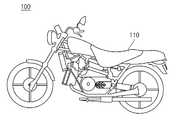
도 1은 본 발명의 일 실시예에 따른 발열 장치의 충전 패치를 도시한 것이다.
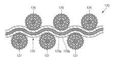
도 2a는 본 발명의 일 실시예에 따른 발열 장치의 발열체를 도시한 것이다.
도 2b는 도 2a의 A 부분 확대도이다.
도 2c는 도 2b의 B-B'선 단면도이다.
도 2d는 도 2b의 C-C'선 단면도이다.
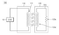
도 2e는 본 발명의 일 실시예예 따른 발열 장치의 충전 패치와 발열체의 동작을 도시한 회로도이다.
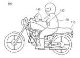
도 3은 본 발명의 일 실시예에 따른 발열 장치의 충전 패치와 발열체가 결합된 상태를 도시한 것이다.
도 4는 본 발명의 다른 실시예에 따른 발열 장치의 충전 패치를 도시한 것이다.
도 5는 본 발명의 또 다른 실시예에 따른 발열 장치의 충전 패치를 도시한 것이다.
도 6은 본 발명의 또 다른 실시예에 따른 발열 장치의 발열체를 도시한 것이다.
도 7은 본 발명의 또 다른 실시예에 따른 발열 장치의 충전 패치 및 발열체를 도시한 것이다.1 illustrates a charging patch of a heating device according to an embodiment of the present invention.
Figure 2a shows a heating element of the heating device according to an embodiment of the present invention.
FIG. 2B is an enlarged view of portion A of FIG. 2A.
FIG. 2C is a cross-sectional view taken along the line BB ′ of FIG. 2B.
FIG. 2D is a cross-sectional view taken along the line CC 'of FIG. 2B.
2E is a circuit diagram illustrating an operation of a charging patch and a heating element of a heating device according to an embodiment of the present invention.
3 is a view showing a state in which a charging patch and a heating element are coupled to a heating device according to an embodiment of the present invention.
4 illustrates a charging patch of a heating device according to another embodiment of the present invention.
5 illustrates a charging patch of a heating device according to still another embodiment of the present invention.
6 illustrates a heating element of a heating device according to still another embodiment of the present invention.
7 illustrates a charging patch and a heating element of a heating device according to another embodiment of the present invention.
본 발명이 속하는 기술분야에 있어서 통상의 지식을 가진 자가 용이하게 실시할 수 있을 정도로 본 발명의 바람직한 실시예를 도면을 참조하여 상세하게 설명하면 다음과 같다.
DETAILED DESCRIPTION OF THE PREFERRED EMBODIMENTS Hereinafter, preferred embodiments of the present invention will be described in detail with reference to the accompanying drawings, so that those skilled in the art can easily carry out the present invention.
이하에서는 본 발명의 일 실시예에 따른 발열 장치의 구성을 설명하도록 한다.Hereinafter, the configuration of the heat generating apparatus according to an embodiment of the present invention.
도 1은 본 발명의 일 실시예에 따른 발열 장치의 충전 패치를 도시한 것이다. 도 2a는 본 발명의 일 실시예에 따른 발열 장치의 발열체를 도시한 것이다. 도 2b는 도 2a의 A 부분 확대도이다. 도 2c는 도 2b의 B-B'선 단면도이다. 도 2d는 도 2b의 C-C'선 단면도이다. 도 2e는 본 발명의 일 실시예예 따른 발열 장치의 충전 패치와 발열체의 동작을 도시한 회로도이다. 도 3은 본 발명의 일 실시예에 따른 발열 장치의 충전 패치와 발열체가 결합된 상태를 도시한 것이다.1 illustrates a charging patch of a heating device according to an embodiment of the present invention. Figure 2a shows a heating element of the heating device according to an embodiment of the present invention. FIG. 2B is an enlarged view of portion A of FIG. 2A. FIG. 2C is a cross-sectional view taken along the line BB ′ of FIG. 2B. FIG. 2D is a cross-sectional view taken along the line CC 'of FIG. 2B. 2E is a circuit diagram illustrating an operation of a charging patch and a heating element of a heating device according to an embodiment of the present invention. 3 is a view showing a state in which a charging patch and a heating element are coupled to a heating device according to an embodiment of the present invention.
도 1 내지 도 3을 참조하면, 본 발명의 일 실시예에 따른 발열 장치(100)는 충전 패치(110), 발열체(120)를 포함한다. 또한, 본 발명의 일 실시예에 따른 발열 장치(100)는 온도 감지부(130), 제어부(140)를 더 포함할 수도 있다.
1 to 3, the
상기 충전 패치(110)는 본 발명의 일 실시예에 따른 발열 장치(100)에서 오토바이의 안장을 형성할 수 있다. 상기 충전 패치(110)는 오토바이에 상기 발열체(120)를 구비한 탑승자가 탑승하면 상기 발열체(120)를 충전하여, 상기 발열체(120)가 발열을 할 수 있도록 한다. 상기 충전 패치(110)는 내부에 코일(111)을 구비한다.The
상기 충전 패치(110)는 외부 또는 내부의 전원(10)으로부터 전류를 인가받으며, 상기 내부 코일(111)에 전류를 인가한다. 물론, 이 때 상기 전원(10)이 직류 전원인 경우 교류 전류로 변환하는 컨버터(Converter)가 추가적으로 필요하다.The
상기 충전 패치(110)는 상기 내부 코일(111)의 전류 흐름에 의해 발생된 자기력을 이용하여 상기 발열체(120)를 충전한다. 이 때, 상기 발열체(120)는 상기 충전 패치(110)와 물리적으로 접촉되어 있지 않은 상태에서 충전, 즉 비접촉 충전을 수행한다. 따라서, 상기 충전 패치(110)가 상기 발열체(120)를 충전함에 있어서, 상기 발열체(120)를 사용하는 사람의 안전을 도모할 수 있다.
The
상기 발열체(120)는 상기 충전 패치(110)와 연계되어 비접촉 충전을 수행하고, 발열을 수행한다. 상기 발열체(120)는 의류의 형태, 보다 상세히 설명하면 오토바이 탑승자의 의류의 형태를 갖는다. 상기 오토바이 탑승자가 상기 발열체(120)를 착용한 상태에서, 상기 오토바이에 탑승을 하면, 상기 충전 패치(110)는 상기 발열체(120)를 충전시킨다. 또한, 상기 발열체(120)는 상기 충전된 전력을 이용하여 발열을 수행한다. 따라서, 상기 오토바이 탑승자가 상기 발열체(120)를 통해 열을 전달받아 보온이 이루어질 수 있다.The
상기 발열체(120)는 이를 위해, 경사(121)와 위사(125)를 포함한다. 상기 경사(121)와 위사(125)는 상호간에 직조되어 상기 발열체(120)를 형성한다. 상기 경사(121)와 위사(125)는 상호간에 수직한 방향으로 형성되며, 서로 지그재그 방식으로 직조되어 상기 발열체(120)를 형성한다.The
상기 경사(121)는 제 1 방향으로 나란하게 형성되며, 상기 제 1 방향에 수직한 제 2 방향으로 일정한 간격을 유지하면서 다수 배열된다. 상기 경사(121)는 상기 제 2 방향으로 배열된 다수의 통상 경사(122) 및 디지털사(123)를 포함한다.The
상기 통상 경사(122)는 원사를 이용하여 형성된다. 여기서, 상기 원사는 의복 제작을 위한 직물을 구성하는 실을 의미한다. 또한, 도 2b 내지 도 2d에는 상기 통상 경사(122)가 여러 가닥의 원사를 꼬아서 단사처럼 만든 겹사 구조로 도시되어 있다. 그러나 상기 통상 경사(122)의 구조를 겹사 구조로 한정하는 것은 아니며, 상기 통상 경사(122)는 한가닥의 원사인 단사로 형성될 수도 있다.The
상기 디지털사(123)는 상기 제 1 방향으로 형성되며, 상기 통상 경사(122)와 나란하게 배열된다. 상기 디지털사(123)는 일단부가 코일의 형태로 형성되어, 상기 충전 패치(110)로부터 인가된 자기력을 이용하여 충전을 수행한다. 상기 디지털사(123)는 상기 충전된 전력을 이용하여 발열을 구행하며, 결과적으로 상기 발열체(120)를 착용한 사람에게 열을 제공한다. 또한, 상기 디지털사(123)가 상기 경사(121)의 일부를 구성하는 것으로 도시 및 설명하였으나, 상기 디지털사(123)는 상기 위사(125)의 일부를 구성하도록 배열되는 것도 가능하며, 상기 디지털사(123)의 형태를 한정하는 것은 아니다. 상기 디지털사(123)는 상기 디지털사(123)의 직경을 기준으로 중심에 위치한 적어도 하나의 금속부(123a), 상기 금속부(123a)를 감싸면서 형성되는 코팅부(123b)를 포함하면서 형성된다. 또한, 상기 금속부(123a)와 상기 코팅부(123b)의 사이에는 상기 코팅부(123b)가 상기 금속부(123a)의 사이 영역으로 인입되지 못하여 형성된 빈 공간인 공극(123c)이 형성될 수도 있고, 상기 코팅부(123b)의 외주연을 감싸는 커버사(미도시)가 더 형성될 수도 있다.The
상기 금속부(123a)는 전기적인 저항이 작고, 반복적인 굽힘에 대한 탄성 회복력이 높은 재질의 금속으로 구성된다. 상기 금속부(123a)는 구리, 구리 합금, 은, 은 합금, 금, 금 합금, 황동 중에서 선택된 적어도 하나 또는 이들의 조합을 이용하여 형성될 수 있다. 또한, 상기 금속부(123a)는 일곱개로 구비되는 것으로 도시되어 있으나, 본 발명의 내용을 이로써 한정하는 것은 아니다.The
상기 코팅부(123b)는 상기 금속부(123a)를 감싸면서 형성된다. 상기 코팅부(123b)는 상기 금속부(123a)에서 발생하는 열은 인체에 도달하도록 하되, 전자파는 인체에 도달하지 못하도록 차단한다. 또한, 상기 코팅부(123b)는 외부 노이즈 전자파가 상기 디지털사(123) 내부의 금속부(123a)에 도달하지 못하도록 차단한다. 이를 위해, 상기 코팅부(1212b)의 재질로서 ETFE(Ethylenetetrafluoroethylene), FEP(Fluorinated Ethylenepropylene), PTFE(Polytetrafluoroethylene), PVDF(Polyvinylidenefluoride), PFA(Perfluoroalkoxy) 및 그 등가물 중 선택된 어느 하나가 사용될 수 있으나 이로서 본 발명의 내용을 한정하는 것은 아니다.The
이러한, 상기 디지털사(123)는 일단이 코일(123d)로 구비되어, 상기 충전 패치(110)의 내부 코일(111)로부터 발생한 자기력을 이용하여 비접촉 충전을 수행한다. 또한, 충전된 상기 디지털사(123)에 전류가 흐르면 저항성 성분(123e)을 통해 발열이 이루어진다. 따라서, 상기 디지털사(123)는 상기 발열체(120)를 착용한 탑승자에게 열을 전달할 수 있다.
One end of the
상기 위사(125)는 상기 경사(121)에 수직한 제 2 방향으로 다수 형성된다. 상기 위사(125)는 상기 제 1 방향으로 일정 간격을 유지하면서 다수 배열되며, 상호간에 나란하게 위치한다. 상기 위사(125)는 상기 경사(121)와 함께 직조되어 상기 발열체(120)를 형성한다. 상기 위사(125)는 상기 통상 경사(121)와 마찬가지로 단사 또는 겹사의 구조를 가질 수 있다.The
상기 위사(125)는 상기 그 배열된 열에 따라서 제 1 위사(126) 및 제 2 위사(127)의 두 그룹으로 구성된다. 상기 제 1 위사(126) 및 제 2 위사(127)는 상호간에 이웃하게 배열된다. 예를 들어, 상기 제 1 위사(126)는 각 홀수열에 위치한 위사이고, 상기 제 2 위사(127)는 각 짝수열에 위치한 위사일 수 있다.
The
상기 온도 감지부(130)는 상기 발열체(120)의 표면 일부에 형성된다. 상기 온도 감지부(130)는 상기 발열체(120)의 온도를 감지한다. 그리고 상기 온도 감지부(130)는 상기 온도를 상기 제어부(140)에 전달한다. 따라서, 상기 온도 감지부(130)는 상기 발열체(120)를 착용한 오토바이 탑승자가 온도를 인지할 수 있도록 한다. 상기 온도 감지부(130)는 상기 발열체(120)의 온도를 감지하기 위해, 통상적인 바이메탈(Bimetal)이나 써미스터(thermistor)를 이용하여 형성될 수 있다. 다만, 상기 온도 감지부(130)의 종류를 한정하는 것은 아니다.
The
상기 제어부(140)는 상기 발열체(120)의 일측에 부착된다. 상기 제어부(140)는 상기 온도 감지부(130)로부터 전달받은 온도 신호를 디스플레이를 통해 표시할 수 있으며, 오토바이 탑승자가 상기 발열체(120)의 온도를 제어할 수 있도록 할 수도 있다. 상기 제어부(140)는 상기 발열체(120)의 내부에 구비된 가변 저항(미도시)의 크기를 조절하여 상기 디지털사(123)를 통과하는 전류량을 제어할 수 있다. 따라서, 상기 제어부(140)는 상기 발열체(120)의 온도를 제어할 수 있다.
The
상기와 같이 하여, 본 발명의 일 실시예에 따른 발열 장치(100)는 오토바이 안장에 형성된 충전 패치(110)와 디지털사(123)를 직조하여 오토바이 탑승자의 의류를 형성하는 발열체(120)를 구비하여, 충전 패치(110)가 발열체(120)를 비접촉 충전시키도록 하여, 사용시 편의성을 도모할 수 있다. 또한, 상기 디지털사(123)는 충전된 전력을 이용하여 발열을 수행함으로써, 상기 발열체(120)를 착용한 오토바이 탑승자에게 용이하게 열을 전달할 수 있다.
As described above, the
이하에서는 본 발명의 다른 실시예에 따른 발열 장치의 구성을 설명하도록 한다. 앞선 실시예와 동일한 구성 및 동작을 갖는 부분에 대해서는 별도로 도시하지 않았으며, 이하에서는 앞선 실시예와의 차이점을 중심으로 설명하기로 한다.Hereinafter, the configuration of a heat generating apparatus according to another embodiment of the present invention. Portions having the same configuration and operation as the foregoing embodiment are not separately illustrated, and will be described below with a focus on differences from the foregoing embodiment.
도 4는 본 발명의 다른 실시예에 따른 발열 장치의 충전 패치를 도시한 것이다.4 illustrates a charging patch of a heating device according to another embodiment of the present invention.
도 4를 참조하면, 본 발명의 다른 실시예에 따른 발열 장치(200)는 충전 패치(210), 발열체(미도시)를 포함한다. 또한, 본 발명의 다른 실시예에 따른 발열 장치(200)는 온도 검출부(미도시), 제어부(미도시)를 더 포함할 수 있다.
Referring to FIG. 4, the
상기 충전 패치(210)는 의자를 구성하는 시트의 형태로 이루어진다. 상기 충전 패치(210)는 상기 발열체(120)를 구비한 사람이 의자인 상기 충전 패치(210)에 앉으면, 상기 발열체(120)를 충전하여 상기 발열체(120)가 발열을 할 수 있도록 한다. 이를 위해, 상기 충전 패치(210)는 내부 코일을 구비하며, 외부 또는 내부의 전원으로부터 전류를 상기 내부 코일에 인가하여 자기력을 발생시킨다. 그리고 상기 발열체(120)는 상기 충전 패치(110)와 비접촉 충전을 수행한다. 따라서, 상기 충전 패치(110)가 상기 발열체(120)를 충전함에 있어서, 상기 발열체(120)를 사용하는 사람의 안전을 도모할 수 있다.
The filling
도 5는 본 발명의 또 다른 실시예에 따른 발열 장치의 충전 패치를 도시한 것이다. 도 6은 본 발명의 또 다른 실시예에 따른 발열 장치의 발열체를 도시한 것이다.5 illustrates a charging patch of a heating device according to still another embodiment of the present invention. 6 illustrates a heating element of a heating device according to still another embodiment of the present invention.
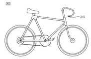
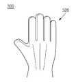
도 5 및 도 6을 참조하면, 본 발명의 또 다른 실시예에 따른 발열 장치(300)는 자전거의 손잡이를 구성하는 충전 패치(310), 장갑을 구성하는 발열체(320)를 포함한다. 또한, 본 발명의 또 다른 실시예에 따른 발열 장치(300)는 온도 감지부(미도시), 제어부(미도시)를 더 포함할 수도 있다.
5 and 6, the
상기 충전 패치(310)는 자전거를 구성하는 손잡이의 형태로 이루어진다. 또한, 상기 충전 패치(310)는 장갑 형태의 상기 발열체(320)를 착용한 사람이 상기 충전 패치(310)를 잡으면, 상기 발열체(320)를 충전하여 상기 발열체(320)가 발열을 할 수 있도록 한다. 이를 위해, 상기 충전 패치(310)는 역시 내부 코일을 구비하며, 외부 또는 내부의 전원으로부터 전류를 상기 내부 코일에 인가하여 자기력을 발생시킨다. 그리고 상기 발열체(320)는 상기 충전 패치(310)와 비접촉 충전을 수행한다.
The charging
상기 발열체(320)는 디지털사를 이용해 이루어지며, 장갑의 형태를 갖는다. 상기 발열체(320)를 손에 착용한 사람이 상기 충전 패치(310)를 잡으면, 상기 발열체(320)는 상기 충전 패치(310)와 비접촉 충전을 수행한다. 또한, 상기 발열체(320)는 상기 충전된 전력을 이용하여, 상기 디지털사에 전류를 인가하며, 그 결과 발열을 수행한다. 따라서, 상기 발열체(320)는 상기 발열체(320)를 착용한 사람의 손에 열을 가하여, 손의 보온을 이룰 수 있다.
The
도 7은 본 발명의 또 다른 실시예에 따른 발열 장치의 충전 패치 및 발열체를 도시한 것이다.7 illustrates a charging patch and a heating element of a heating device according to another embodiment of the present invention.
도 7을 참조하면, 본 발명의 또 다른 실시예에 따른 발열 장치(400)는 충전 패치(410), 발열체(420)를 포함한다. 또한, 본 발명의 또 다른 실시예에 따른 발열 장치(400)는 온도 감지부(미도시), 제어부(미도시)를 더 포함할 수도 있다.
Referring to FIG. 7, the
상기 충전 패치(410)는 커튼봉 형태로 구성된다. 상기 충전 패치(410)는 상기 발열체(420)가 상기 커튼봉의 중앙으로 이동하는 경우, 상기 발열체(420)를 비접촉 충전한다. 이를 위해, 상기 충전 패치(410)는 상기 커튼봉의 중앙에 밀집되어 형성된 내부 코일을 포함한다. 따라서, 상기 발열체(420)가 형성된 커튼이 햇빛 등을 가리기 위해 쳐지는 경우, 즉 상기 발열체(420)가 상기 충전 패치(410)의 중앙까지 커튼봉을 따라 이동하는 경우, 상기 충전 패치(410)는 내부 코일에 전류를 인가한다. 결국, 상기 충전 패치(410)로부터 자기력이 발생하므로, 상기 충전 패치(410)를 이용하여 상기 발열체(420)가 비접촉 충전을 수행한다.
The filling
상기 발열체(420)는 디지털사를 이용하여 직조되어 커튼을 형성한다. 상기 발열체(420)로 이루어진 커튼이 쳐지는 경우, 상기 발열체(420)는 상기 충전 패치(410)로부터 발생한 자기력을 이용하여 비접촉 충전을 수행한다. 또한, 상기 발열체(420)는 충전된 전력을 이용하여 디지털사에 전류를 인가하며, 그 결과 발열을 수행한다. 또한, 상기 발열체(420)를 이용한 커튼이 걷힌 경우, 상기 발열체(420)는 상기 충전 패치(410)와 이격된 상태가 되어, 비접촉 충전을 수행하지 않으며, 그 결과 상기 발열체(420)는 발열을 수행하지 않을 수 있다.
The
이상에서 설명한 것은 본 발명에 의한 발열 장치를 실시하기 위한 실시예에 불과한 것으로서, 본 발명은 상기 실시예에 한정되지 않고, 이하의 특허청구범위에서 청구하는 바와 같이 본 발명의 요지를 벗어남이 없이 당해 발명이 속하는 분야에서 통상의 지식을 가진 자라면 누구든지 다양한 변경 실시가 가능한 범위까지 본 발명의 기술적 정신이 있다고 할 것이다.
What has been described above is merely an embodiment for carrying out the heat generating device according to the present invention, and the present invention is not limited to the above embodiment, and as claimed in the following claims, without departing from the gist of the present invention. Anyone with ordinary knowledge in the field of the invention will have the technical spirit of the present invention to the extent that various modifications can be made.
100, 200, 300, 400; 발열 장치
110, 210, 310, 410; 충전 패치 120, 320, 420; 발열체
123; 디지털사 130; 온도 감지부
140; 제어부100, 200, 300, 400; Heating device
110, 210, 310, 410; Filling
123;
140; Control
Claims (10)
Translated fromKorean상기 충전 패치의 자기력을 수신하여 비접촉 충전을 수행하고, 충전된 전력을 이용하여 발열을 수행하는 디지털사를 포함하는 발열체를 포함하고,
상기 디지털사는 상기 발열체의 내부에 직물과 함께 직조되어 형성된 발열 장치.A charging patch that emits a magnetic force when current flows through the internal coil; And
Receiving a magnetic force of the charging patch to perform a non-contact charging, and comprises a heating element including a digital yarn to generate heat using the charged power,
The digital yarn is a heating device formed by weaving together with a fabric inside the heating element.
상기 충전 패치는 배터리로부터 전력을 인가받아, 상기 내부 코일에 전류를 인가하는 발열 장치.The method of claim 1,
The charging patch is a heating device that receives power from a battery, and applies a current to the internal coil.
상기 디지털사의 일단은 코일 형태로 형성되어, 상기 충전 패치의 자기력을 수신하는 발열 장치.The method of claim 1,
One end of the digital yarn is formed in the form of a coil, the heating device for receiving a magnetic force of the charging patch.
상기 디지털사는 상기 발열체를 직조하는 경사 및 위사 중에서 선택된 적어도 하나의 일부를 형성하는 발열 장치.The method of claim 1,
And the digital yarns form at least one portion selected from warp and weft yarns for weaving the heat generating elements.
상기 충전 패치는 오토바이의 안장을 형성하고, 상기 발열체는 직조되어 상기 오토바이를 탑승하는 사람의 의복을 형성하는 발열 장치.The method of claim 1,
The charging patch forms the saddle of the motorcycle, the heating element is woven to form a garment of the person riding the motorcycle.
상기 충전 패치는 의자를 형성하고, 상기 발열체는 직조되어 상기 의자를 이용하는 사람의 의복을 형성하는 발열 장치.The method of claim 1,
And the filling patch forms a chair, and the heating element is woven to form a garment of a person using the chair.
상기 충전 패치는 자전거의 손잡이를 형성하고, 상기 발열체는 직조되어 상기 자전거를 이용하는 사람의 장갑을 형성하는 발열 장치.The method of claim 1,
The charging patch forms a handle of the bicycle, and the heating element is woven to form a glove of a person using the bicycle.
상기 충전 패치는 커튼의 커튼봉을 형성하고, 상기 발열체는 직조되어 상기 커튼을 형성하는 발열 장치.The method of claim 1,
The filling patch forms a curtain rod of the curtain, the heating element is woven to form the curtain.
상기 발열체의 표면에 부착되어 상기 발열체의 온도를 감지하는 바이메탈 또는 써미스터로 이루어진 온도 감지부가 더 형성된 발열 장치.The method of claim 1,
And a temperature sensing unit including a bimetal or a thermistor attached to a surface of the heating element and sensing the temperature of the heating element.
상기 발열체는 내부에 가변 저항을 구비하고, 상기 가변 저항의 크기를 제어하여 상기 디지털사에 흐르는 전류량을 제어하는 제어부가 더 형성된 발열 장치.The method of claim 1,
The heating element is provided with a variable resistor therein, the heating device further comprises a control unit for controlling the amount of the current flowing through the digital yarn by controlling the size of the variable resistor.
Priority Applications (4)
| Application Number | Priority Date | Filing Date | Title |
|---|---|---|---|
| KR1020100038390AKR20110118963A (en) | 2010-04-26 | 2010-04-26 | Non-contact charging heating device |
| PCT/KR2010/009484WO2011136461A1 (en) | 2010-04-26 | 2010-12-29 | Contactlessly chargeable heater |
| CN201080022945.3ACN102450092B (en) | 2010-04-26 | 2010-12-29 | Contactlessly chargeable heater |
| US13/322,585US8907257B2 (en) | 2010-04-26 | 2010-12-29 | Contactlessly chargeable heater |
Applications Claiming Priority (1)
| Application Number | Priority Date | Filing Date | Title |
|---|---|---|---|
| KR1020100038390AKR20110118963A (en) | 2010-04-26 | 2010-04-26 | Non-contact charging heating device |
Publications (1)
| Publication Number | Publication Date |
|---|---|
| KR20110118963Atrue KR20110118963A (en) | 2011-11-02 |
Family
ID=44861724
Family Applications (1)
| Application Number | Title | Priority Date | Filing Date |
|---|---|---|---|
| KR1020100038390ACeasedKR20110118963A (en) | 2010-04-26 | 2010-04-26 | Non-contact charging heating device |
Country Status (4)
| Country | Link |
|---|---|
| US (1) | US8907257B2 (en) |
| KR (1) | KR20110118963A (en) |
| CN (1) | CN102450092B (en) |
| WO (1) | WO2011136461A1 (en) |
Families Citing this family (199)
| Publication number | Priority date | Publication date | Assignee | Title |
|---|---|---|---|---|
| US9876394B1 (en) | 2014-05-07 | 2018-01-23 | Energous Corporation | Boost-charger-boost system for enhanced power delivery |
| US9438045B1 (en) | 2013-05-10 | 2016-09-06 | Energous Corporation | Methods and systems for maximum power point transfer in receivers |
| US10128693B2 (en) | 2014-07-14 | 2018-11-13 | Energous Corporation | System and method for providing health safety in a wireless power transmission system |
| US9941754B2 (en) | 2012-07-06 | 2018-04-10 | Energous Corporation | Wireless power transmission with selective range |
| US9887739B2 (en) | 2012-07-06 | 2018-02-06 | Energous Corporation | Systems and methods for wireless power transmission by comparing voltage levels associated with power waves transmitted by antennas of a plurality of antennas of a transmitter to determine appropriate phase adjustments for the power waves |
| US20150326070A1 (en) | 2014-05-07 | 2015-11-12 | Energous Corporation | Methods and Systems for Maximum Power Point Transfer in Receivers |
| US20140008993A1 (en) | 2012-07-06 | 2014-01-09 | DvineWave Inc. | Methodology for pocket-forming |
| US10218227B2 (en) | 2014-05-07 | 2019-02-26 | Energous Corporation | Compact PIFA antenna |
| US9831718B2 (en) | 2013-07-25 | 2017-11-28 | Energous Corporation | TV with integrated wireless power transmitter |
| US10211680B2 (en) | 2013-07-19 | 2019-02-19 | Energous Corporation | Method for 3 dimensional pocket-forming |
| US9368020B1 (en) | 2013-05-10 | 2016-06-14 | Energous Corporation | Off-premises alert system and method for wireless power receivers in a wireless power network |
| US10230266B1 (en) | 2014-02-06 | 2019-03-12 | Energous Corporation | Wireless power receivers that communicate status data indicating wireless power transmission effectiveness with a transmitter using a built-in communications component of a mobile device, and methods of use thereof |
| US11502551B2 (en) | 2012-07-06 | 2022-11-15 | Energous Corporation | Wirelessly charging multiple wireless-power receivers using different subsets of an antenna array to focus energy at different locations |
| US9882427B2 (en) | 2013-05-10 | 2018-01-30 | Energous Corporation | Wireless power delivery using a base station to control operations of a plurality of wireless power transmitters |
| US10063105B2 (en) | 2013-07-11 | 2018-08-28 | Energous Corporation | Proximity transmitters for wireless power charging systems |
| US9824815B2 (en) | 2013-05-10 | 2017-11-21 | Energous Corporation | Wireless charging and powering of healthcare gadgets and sensors |
| US9948135B2 (en) | 2015-09-22 | 2018-04-17 | Energous Corporation | Systems and methods for identifying sensitive objects in a wireless charging transmission field |
| US9843213B2 (en) | 2013-08-06 | 2017-12-12 | Energous Corporation | Social power sharing for mobile devices based on pocket-forming |
| US9893768B2 (en) | 2012-07-06 | 2018-02-13 | Energous Corporation | Methodology for multiple pocket-forming |
| US9991741B1 (en) | 2014-07-14 | 2018-06-05 | Energous Corporation | System for tracking and reporting status and usage information in a wireless power management system |
| US9853692B1 (en) | 2014-05-23 | 2017-12-26 | Energous Corporation | Systems and methods for wireless power transmission |
| US9143000B2 (en) | 2012-07-06 | 2015-09-22 | Energous Corporation | Portable wireless charging pad |
| US10992187B2 (en) | 2012-07-06 | 2021-04-27 | Energous Corporation | System and methods of using electromagnetic waves to wirelessly deliver power to electronic devices |
| US9887584B1 (en) | 2014-08-21 | 2018-02-06 | Energous Corporation | Systems and methods for a configuration web service to provide configuration of a wireless power transmitter within a wireless power transmission system |
| US10256657B2 (en) | 2015-12-24 | 2019-04-09 | Energous Corporation | Antenna having coaxial structure for near field wireless power charging |
| US9825674B1 (en) | 2014-05-23 | 2017-11-21 | Energous Corporation | Enhanced transmitter that selects configurations of antenna elements for performing wireless power transmission and receiving functions |
| US9941747B2 (en) | 2014-07-14 | 2018-04-10 | Energous Corporation | System and method for manually selecting and deselecting devices to charge in a wireless power network |
| US10038337B1 (en) | 2013-09-16 | 2018-07-31 | Energous Corporation | Wireless power supply for rescue devices |
| US9847677B1 (en) | 2013-10-10 | 2017-12-19 | Energous Corporation | Wireless charging and powering of healthcare gadgets and sensors |
| US9787103B1 (en) | 2013-08-06 | 2017-10-10 | Energous Corporation | Systems and methods for wirelessly delivering power to electronic devices that are unable to communicate with a transmitter |
| US9812890B1 (en) | 2013-07-11 | 2017-11-07 | Energous Corporation | Portable wireless charging pad |
| US9838083B2 (en) | 2014-07-21 | 2017-12-05 | Energous Corporation | Systems and methods for communication with remote management systems |
| US9847679B2 (en) | 2014-05-07 | 2017-12-19 | Energous Corporation | System and method for controlling communication between wireless power transmitter managers |
| US9882430B1 (en) | 2014-05-07 | 2018-01-30 | Energous Corporation | Cluster management of transmitters in a wireless power transmission system |
| US10263432B1 (en) | 2013-06-25 | 2019-04-16 | Energous Corporation | Multi-mode transmitter with an antenna array for delivering wireless power and providing Wi-Fi access |
| US9941707B1 (en) | 2013-07-19 | 2018-04-10 | Energous Corporation | Home base station for multiple room coverage with multiple transmitters |
| US9859756B2 (en) | 2012-07-06 | 2018-01-02 | Energous Corporation | Transmittersand methods for adjusting wireless power transmission based on information from receivers |
| US10141768B2 (en) | 2013-06-03 | 2018-11-27 | Energous Corporation | Systems and methods for maximizing wireless power transfer efficiency by instructing a user to change a receiver device's position |
| US10992185B2 (en) | 2012-07-06 | 2021-04-27 | Energous Corporation | Systems and methods of using electromagnetic waves to wirelessly deliver power to game controllers |
| US10148097B1 (en) | 2013-11-08 | 2018-12-04 | Energous Corporation | Systems and methods for using a predetermined number of communication channels of a wireless power transmitter to communicate with different wireless power receivers |
| US9871398B1 (en) | 2013-07-01 | 2018-01-16 | Energous Corporation | Hybrid charging method for wireless power transmission based on pocket-forming |
| US9876648B2 (en) | 2014-08-21 | 2018-01-23 | Energous Corporation | System and method to control a wireless power transmission system by configuration of wireless power transmission control parameters |
| US10211674B1 (en) | 2013-06-12 | 2019-02-19 | Energous Corporation | Wireless charging using selected reflectors |
| US9891669B2 (en) | 2014-08-21 | 2018-02-13 | Energous Corporation | Systems and methods for a configuration web service to provide configuration of a wireless power transmitter within a wireless power transmission system |
| US9876379B1 (en) | 2013-07-11 | 2018-01-23 | Energous Corporation | Wireless charging and powering of electronic devices in a vehicle |
| US10291066B1 (en) | 2014-05-07 | 2019-05-14 | Energous Corporation | Power transmission control systems and methods |
| US10075008B1 (en) | 2014-07-14 | 2018-09-11 | Energous Corporation | Systems and methods for manually adjusting when receiving electronic devices are scheduled to receive wirelessly delivered power from a wireless power transmitter in a wireless power network |
| US9859757B1 (en) | 2013-07-25 | 2018-01-02 | Energous Corporation | Antenna tile arrangements in electronic device enclosures |
| US9793758B2 (en) | 2014-05-23 | 2017-10-17 | Energous Corporation | Enhanced transmitter using frequency control for wireless power transmission |
| US10199835B2 (en) | 2015-12-29 | 2019-02-05 | Energous Corporation | Radar motion detection using stepped frequency in wireless power transmission system |
| US10206185B2 (en) | 2013-05-10 | 2019-02-12 | Energous Corporation | System and methods for wireless power transmission to an electronic device in accordance with user-defined restrictions |
| US10439448B2 (en) | 2014-08-21 | 2019-10-08 | Energous Corporation | Systems and methods for automatically testing the communication between wireless power transmitter and wireless power receiver |
| US9252628B2 (en) | 2013-05-10 | 2016-02-02 | Energous Corporation | Laptop computer as a transmitter for wireless charging |
| US10128699B2 (en) | 2014-07-14 | 2018-11-13 | Energous Corporation | Systems and methods of providing wireless power using receiver device sensor inputs |
| US10090886B1 (en) | 2014-07-14 | 2018-10-02 | Energous Corporation | System and method for enabling automatic charging schedules in a wireless power network to one or more devices |
| US10141791B2 (en) | 2014-05-07 | 2018-11-27 | Energous Corporation | Systems and methods for controlling communications during wireless transmission of power using application programming interfaces |
| US10211682B2 (en) | 2014-05-07 | 2019-02-19 | Energous Corporation | Systems and methods for controlling operation of a transmitter of a wireless power network based on user instructions received from an authenticated computing device powered or charged by a receiver of the wireless power network |
| US10224758B2 (en) | 2013-05-10 | 2019-03-05 | Energous Corporation | Wireless powering of electronic devices with selective delivery range |
| US20150162751A1 (en)* | 2013-05-10 | 2015-06-11 | DvineWave Inc. | Wireless charging of clothing and smart fabrics |
| US10124754B1 (en) | 2013-07-19 | 2018-11-13 | Energous Corporation | Wireless charging and powering of electronic sensors in a vehicle |
| US9806564B2 (en) | 2014-05-07 | 2017-10-31 | Energous Corporation | Integrated rectifier and boost converter for wireless power transmission |
| US9124125B2 (en) | 2013-05-10 | 2015-09-01 | Energous Corporation | Wireless power transmission with selective range |
| US9859797B1 (en) | 2014-05-07 | 2018-01-02 | Energous Corporation | Synchronous rectifier design for wireless power receiver |
| US9912199B2 (en) | 2012-07-06 | 2018-03-06 | Energous Corporation | Receivers for wireless power transmission |
| US9900057B2 (en) | 2012-07-06 | 2018-02-20 | Energous Corporation | Systems and methods for assigning groups of antenas of a wireless power transmitter to different wireless power receivers, and determining effective phases to use for wirelessly transmitting power using the assigned groups of antennas |
| US9899861B1 (en) | 2013-10-10 | 2018-02-20 | Energous Corporation | Wireless charging methods and systems for game controllers, based on pocket-forming |
| US10965164B2 (en) | 2012-07-06 | 2021-03-30 | Energous Corporation | Systems and methods of wirelessly delivering power to a receiver device |
| US10381880B2 (en) | 2014-07-21 | 2019-08-13 | Energous Corporation | Integrated antenna structure arrays for wireless power transmission |
| US10063106B2 (en) | 2014-05-23 | 2018-08-28 | Energous Corporation | System and method for a self-system analysis in a wireless power transmission network |
| US10050462B1 (en) | 2013-08-06 | 2018-08-14 | Energous Corporation | Social power sharing for mobile devices based on pocket-forming |
| US9966765B1 (en) | 2013-06-25 | 2018-05-08 | Energous Corporation | Multi-mode transmitter |
| US10186913B2 (en) | 2012-07-06 | 2019-01-22 | Energous Corporation | System and methods for pocket-forming based on constructive and destructive interferences to power one or more wireless power receivers using a wireless power transmitter including a plurality of antennas |
| US10063064B1 (en) | 2014-05-23 | 2018-08-28 | Energous Corporation | System and method for generating a power receiver identifier in a wireless power network |
| US9867062B1 (en) | 2014-07-21 | 2018-01-09 | Energous Corporation | System and methods for using a remote server to authorize a receiving device that has requested wireless power and to determine whether another receiving device should request wireless power in a wireless power transmission system |
| US10291055B1 (en) | 2014-12-29 | 2019-05-14 | Energous Corporation | Systems and methods for controlling far-field wireless power transmission based on battery power levels of a receiving device |
| US9939864B1 (en) | 2014-08-21 | 2018-04-10 | Energous Corporation | System and method to control a wireless power transmission system by configuration of wireless power transmission control parameters |
| US9906065B2 (en) | 2012-07-06 | 2018-02-27 | Energous Corporation | Systems and methods of transmitting power transmission waves based on signals received at first and second subsets of a transmitter's antenna array |
| US10224982B1 (en) | 2013-07-11 | 2019-03-05 | Energous Corporation | Wireless power transmitters for transmitting wireless power and tracking whether wireless power receivers are within authorized locations |
| US12057715B2 (en) | 2012-07-06 | 2024-08-06 | Energous Corporation | Systems and methods of wirelessly delivering power to a wireless-power receiver device in response to a change of orientation of the wireless-power receiver device |
| US9973021B2 (en) | 2012-07-06 | 2018-05-15 | Energous Corporation | Receivers for wireless power transmission |
| US9899873B2 (en) | 2014-05-23 | 2018-02-20 | Energous Corporation | System and method for generating a power receiver identifier in a wireless power network |
| US9923386B1 (en) | 2012-07-06 | 2018-03-20 | Energous Corporation | Systems and methods for wireless power transmission by modifying a number of antenna elements used to transmit power waves to a receiver |
| US9843201B1 (en) | 2012-07-06 | 2017-12-12 | Energous Corporation | Wireless power transmitter that selects antenna sets for transmitting wireless power to a receiver based on location of the receiver, and methods of use thereof |
| US10090699B1 (en) | 2013-11-01 | 2018-10-02 | Energous Corporation | Wireless powered house |
| US9893554B2 (en) | 2014-07-14 | 2018-02-13 | Energous Corporation | System and method for providing health safety in a wireless power transmission system |
| US10193396B1 (en) | 2014-05-07 | 2019-01-29 | Energous Corporation | Cluster management of transmitters in a wireless power transmission system |
| US10270261B2 (en) | 2015-09-16 | 2019-04-23 | Energous Corporation | Systems and methods of object detection in wireless power charging systems |
| US10243414B1 (en) | 2014-05-07 | 2019-03-26 | Energous Corporation | Wearable device with wireless power and payload receiver |
| US10312715B2 (en) | 2015-09-16 | 2019-06-04 | Energous Corporation | Systems and methods for wireless power charging |
| US10103582B2 (en) | 2012-07-06 | 2018-10-16 | Energous Corporation | Transmitters for wireless power transmission |
| US9853458B1 (en) | 2014-05-07 | 2017-12-26 | Energous Corporation | Systems and methods for device and power receiver pairing |
| US10008889B2 (en) | 2014-08-21 | 2018-06-26 | Energous Corporation | Method for automatically testing the operational status of a wireless power receiver in a wireless power transmission system |
| US10199849B1 (en) | 2014-08-21 | 2019-02-05 | Energous Corporation | Method for automatically testing the operational status of a wireless power receiver in a wireless power transmission system |
| US9954374B1 (en) | 2014-05-23 | 2018-04-24 | Energous Corporation | System and method for self-system analysis for detecting a fault in a wireless power transmission Network |
| US9893555B1 (en) | 2013-10-10 | 2018-02-13 | Energous Corporation | Wireless charging of tools using a toolbox transmitter |
| US10223717B1 (en) | 2014-05-23 | 2019-03-05 | Energous Corporation | Systems and methods for payment-based authorization of wireless power transmission service |
| US10205239B1 (en) | 2014-05-07 | 2019-02-12 | Energous Corporation | Compact PIFA antenna |
| US9537357B2 (en) | 2013-05-10 | 2017-01-03 | Energous Corporation | Wireless sound charging methods and systems for game controllers, based on pocket-forming |
| US9866279B2 (en) | 2013-05-10 | 2018-01-09 | Energous Corporation | Systems and methods for selecting which power transmitter should deliver wireless power to a receiving device in a wireless power delivery network |
| US9419443B2 (en) | 2013-05-10 | 2016-08-16 | Energous Corporation | Transducer sound arrangement for pocket-forming |
| US9538382B2 (en) | 2013-05-10 | 2017-01-03 | Energous Corporation | System and method for smart registration of wireless power receivers in a wireless power network |
| US9819230B2 (en) | 2014-05-07 | 2017-11-14 | Energous Corporation | Enhanced receiver for wireless power transmission |
| US10103552B1 (en) | 2013-06-03 | 2018-10-16 | Energous Corporation | Protocols for authenticated wireless power transmission |
| US10003211B1 (en) | 2013-06-17 | 2018-06-19 | Energous Corporation | Battery life of portable electronic devices |
| US10021523B2 (en) | 2013-07-11 | 2018-07-10 | Energous Corporation | Proximity transmitters for wireless power charging systems |
| US9979440B1 (en) | 2013-07-25 | 2018-05-22 | Energous Corporation | Antenna tile arrangements configured to operate as one functional unit |
| US10075017B2 (en) | 2014-02-06 | 2018-09-11 | Energous Corporation | External or internal wireless power receiver with spaced-apart antenna elements for charging or powering mobile devices using wirelessly delivered power |
| US9935482B1 (en) | 2014-02-06 | 2018-04-03 | Energous Corporation | Wireless power transmitters that transmit at determined times based on power availability and consumption at a receiving mobile device |
| US9966784B2 (en) | 2014-06-03 | 2018-05-08 | Energous Corporation | Systems and methods for extending battery life of portable electronic devices charged by sound |
| US10158257B2 (en) | 2014-05-01 | 2018-12-18 | Energous Corporation | System and methods for using sound waves to wirelessly deliver power to electronic devices |
| US10170917B1 (en) | 2014-05-07 | 2019-01-01 | Energous Corporation | Systems and methods for managing and controlling a wireless power network by establishing time intervals during which receivers communicate with a transmitter |
| US10153653B1 (en) | 2014-05-07 | 2018-12-11 | Energous Corporation | Systems and methods for using application programming interfaces to control communications between a transmitter and a receiver |
| US10153645B1 (en) | 2014-05-07 | 2018-12-11 | Energous Corporation | Systems and methods for designating a master power transmitter in a cluster of wireless power transmitters |
| US9800172B1 (en) | 2014-05-07 | 2017-10-24 | Energous Corporation | Integrated rectifier and boost converter for boosting voltage received from wireless power transmission waves |
| US9973008B1 (en) | 2014-05-07 | 2018-05-15 | Energous Corporation | Wireless power receiver with boost converters directly coupled to a storage element |
| US9876536B1 (en) | 2014-05-23 | 2018-01-23 | Energous Corporation | Systems and methods for assigning groups of antennas to transmit wireless power to different wireless power receivers |
| US10068703B1 (en) | 2014-07-21 | 2018-09-04 | Energous Corporation | Integrated miniature PIFA with artificial magnetic conductor metamaterials |
| US9871301B2 (en) | 2014-07-21 | 2018-01-16 | Energous Corporation | Integrated miniature PIFA with artificial magnetic conductor metamaterials |
| US10116143B1 (en) | 2014-07-21 | 2018-10-30 | Energous Corporation | Integrated antenna arrays for wireless power transmission |
| US9965009B1 (en) | 2014-08-21 | 2018-05-08 | Energous Corporation | Systems and methods for assigning a power receiver to individual power transmitters based on location of the power receiver |
| US9917477B1 (en) | 2014-08-21 | 2018-03-13 | Energous Corporation | Systems and methods for automatically testing the communication between power transmitter and wireless receiver |
| US10122415B2 (en) | 2014-12-27 | 2018-11-06 | Energous Corporation | Systems and methods for assigning a set of antennas of a wireless power transmitter to a wireless power receiver based on a location of the wireless power receiver |
| US9893535B2 (en) | 2015-02-13 | 2018-02-13 | Energous Corporation | Systems and methods for determining optimal charging positions to maximize efficiency of power received from wirelessly delivered sound wave energy |
| US20160374149A1 (en)* | 2015-06-17 | 2016-12-22 | Apollo Sun Global Co., Ltd. | Thermal fiber carpet structure |
| US9906275B2 (en) | 2015-09-15 | 2018-02-27 | Energous Corporation | Identifying receivers in a wireless charging transmission field |
| US10523033B2 (en) | 2015-09-15 | 2019-12-31 | Energous Corporation | Receiver devices configured to determine location within a transmission field |
| US12283828B2 (en) | 2015-09-15 | 2025-04-22 | Energous Corporation | Receiver devices configured to determine location within a transmission field |
| US9893538B1 (en) | 2015-09-16 | 2018-02-13 | Energous Corporation | Systems and methods of object detection in wireless power charging systems |
| US9941752B2 (en) | 2015-09-16 | 2018-04-10 | Energous Corporation | Systems and methods of object detection in wireless power charging systems |
| US10211685B2 (en) | 2015-09-16 | 2019-02-19 | Energous Corporation | Systems and methods for real or near real time wireless communications between a wireless power transmitter and a wireless power receiver |
| US10186893B2 (en) | 2015-09-16 | 2019-01-22 | Energous Corporation | Systems and methods for real time or near real time wireless communications between a wireless power transmitter and a wireless power receiver |
| US9871387B1 (en) | 2015-09-16 | 2018-01-16 | Energous Corporation | Systems and methods of object detection using one or more video cameras in wireless power charging systems |
| US10199850B2 (en) | 2015-09-16 | 2019-02-05 | Energous Corporation | Systems and methods for wirelessly transmitting power from a transmitter to a receiver by determining refined locations of the receiver in a segmented transmission field associated with the transmitter |
| US10158259B1 (en) | 2015-09-16 | 2018-12-18 | Energous Corporation | Systems and methods for identifying receivers in a transmission field by transmitting exploratory power waves towards different segments of a transmission field |
| US10008875B1 (en) | 2015-09-16 | 2018-06-26 | Energous Corporation | Wireless power transmitter configured to transmit power waves to a predicted location of a moving wireless power receiver |
| US11710321B2 (en) | 2015-09-16 | 2023-07-25 | Energous Corporation | Systems and methods of object detection in wireless power charging systems |
| US10778041B2 (en) | 2015-09-16 | 2020-09-15 | Energous Corporation | Systems and methods for generating power waves in a wireless power transmission system |
| US10135294B1 (en) | 2015-09-22 | 2018-11-20 | Energous Corporation | Systems and methods for preconfiguring transmission devices for power wave transmissions based on location data of one or more receivers |
| US10128686B1 (en) | 2015-09-22 | 2018-11-13 | Energous Corporation | Systems and methods for identifying receiver locations using sensor technologies |
| US10135295B2 (en) | 2015-09-22 | 2018-11-20 | Energous Corporation | Systems and methods for nullifying energy levels for wireless power transmission waves |
| US10020678B1 (en) | 2015-09-22 | 2018-07-10 | Energous Corporation | Systems and methods for selecting antennas to generate and transmit power transmission waves |
| US10050470B1 (en) | 2015-09-22 | 2018-08-14 | Energous Corporation | Wireless power transmission device having antennas oriented in three dimensions |
| US10153660B1 (en) | 2015-09-22 | 2018-12-11 | Energous Corporation | Systems and methods for preconfiguring sensor data for wireless charging systems |
| US10033222B1 (en) | 2015-09-22 | 2018-07-24 | Energous Corporation | Systems and methods for determining and generating a waveform for wireless power transmission waves |
| US10027168B2 (en) | 2015-09-22 | 2018-07-17 | Energous Corporation | Systems and methods for generating and transmitting wireless power transmission waves using antennas having a spacing that is selected by the transmitter |
| US10333332B1 (en) | 2015-10-13 | 2019-06-25 | Energous Corporation | Cross-polarized dipole antenna |
| US10734717B2 (en) | 2015-10-13 | 2020-08-04 | Energous Corporation | 3D ceramic mold antenna |
| US9853485B2 (en) | 2015-10-28 | 2017-12-26 | Energous Corporation | Antenna for wireless charging systems |
| US9899744B1 (en) | 2015-10-28 | 2018-02-20 | Energous Corporation | Antenna for wireless charging systems |
| US10135112B1 (en) | 2015-11-02 | 2018-11-20 | Energous Corporation | 3D antenna mount |
| US10027180B1 (en) | 2015-11-02 | 2018-07-17 | Energous Corporation | 3D triple linear antenna that acts as heat sink |
| US10063108B1 (en) | 2015-11-02 | 2018-08-28 | Energous Corporation | Stamped three-dimensional antenna |
| US10079515B2 (en) | 2016-12-12 | 2018-09-18 | Energous Corporation | Near-field RF charging pad with multi-band antenna element with adaptive loading to efficiently charge an electronic device at any position on the pad |
| US10320446B2 (en) | 2015-12-24 | 2019-06-11 | Energous Corporation | Miniaturized highly-efficient designs for near-field power transfer system |
| US10038332B1 (en) | 2015-12-24 | 2018-07-31 | Energous Corporation | Systems and methods of wireless power charging through multiple receiving devices |
| US10027159B2 (en) | 2015-12-24 | 2018-07-17 | Energous Corporation | Antenna for transmitting wireless power signals |
| US10186892B2 (en) | 2015-12-24 | 2019-01-22 | Energous Corporation | Receiver device with antennas positioned in gaps |
| US11863001B2 (en) | 2015-12-24 | 2024-01-02 | Energous Corporation | Near-field antenna for wireless power transmission with antenna elements that follow meandering patterns |
| US10256677B2 (en) | 2016-12-12 | 2019-04-09 | Energous Corporation | Near-field RF charging pad with adaptive loading to efficiently charge an electronic device at any position on the pad |
| US10164478B2 (en) | 2015-12-29 | 2018-12-25 | Energous Corporation | Modular antenna boards in wireless power transmission systems |
| US20170273282A1 (en)* | 2016-03-28 | 2017-09-28 | Apollo Sun Global Co., Ltd. | Aquaculture heating device |
| US10396584B2 (en)* | 2016-04-25 | 2019-08-27 | Visteon Global Technologies, Inc. | Wireless charging steering wheel |
| US10387435B2 (en)* | 2016-07-27 | 2019-08-20 | Microsoft Technology Licensing, Llc | Computer application query suggestions |
| US10923954B2 (en) | 2016-11-03 | 2021-02-16 | Energous Corporation | Wireless power receiver with a synchronous rectifier |
| CN116455101A (en) | 2016-12-12 | 2023-07-18 | 艾诺格思公司 | Transmitter integrated circuit |
| US10389161B2 (en) | 2017-03-15 | 2019-08-20 | Energous Corporation | Surface mount dielectric antennas for wireless power transmitters |
| US10439442B2 (en) | 2017-01-24 | 2019-10-08 | Energous Corporation | Microstrip antennas for wireless power transmitters |
| US10680319B2 (en) | 2017-01-06 | 2020-06-09 | Energous Corporation | Devices and methods for reducing mutual coupling effects in wireless power transmission systems |
| US11011942B2 (en) | 2017-03-30 | 2021-05-18 | Energous Corporation | Flat antennas having two or more resonant frequencies for use in wireless power transmission systems |
| US10511097B2 (en) | 2017-05-12 | 2019-12-17 | Energous Corporation | Near-field antennas for accumulating energy at a near-field distance with minimal far-field gain |
| US12074460B2 (en) | 2017-05-16 | 2024-08-27 | Wireless Electrical Grid Lan, Wigl Inc. | Rechargeable wireless power bank and method of using |
| US11462949B2 (en) | 2017-05-16 | 2022-10-04 | Wireless electrical Grid LAN, WiGL Inc | Wireless charging method and system |
| US12074452B2 (en) | 2017-05-16 | 2024-08-27 | Wireless Electrical Grid Lan, Wigl Inc. | Networked wireless charging system |
| CN107140074A (en)* | 2017-06-21 | 2017-09-08 | 浙江春风动力股份有限公司 | A kind of two-wheeled motor vehicle and its seat cushion heating system |
| US10848853B2 (en) | 2017-06-23 | 2020-11-24 | Energous Corporation | Systems, methods, and devices for utilizing a wire of a sound-producing device as an antenna for receipt of wirelessly delivered power |
| GB2562548B (en)* | 2017-09-20 | 2019-09-11 | Kymira Ltd | Wireless power and data transfer via resonant yarn structure |
| US10122219B1 (en) | 2017-10-10 | 2018-11-06 | Energous Corporation | Systems, methods, and devices for using a battery as a antenna for receiving wirelessly delivered power from radio frequency power waves |
| US11342798B2 (en) | 2017-10-30 | 2022-05-24 | Energous Corporation | Systems and methods for managing coexistence of wireless-power signals and data signals operating in a same frequency band |
| US10615647B2 (en) | 2018-02-02 | 2020-04-07 | Energous Corporation | Systems and methods for detecting wireless power receivers and other objects at a near-field charging pad |
| US11159057B2 (en) | 2018-03-14 | 2021-10-26 | Energous Corporation | Loop antennas with selectively-activated feeds to control propagation patterns of wireless power signals |
| US11515732B2 (en) | 2018-06-25 | 2022-11-29 | Energous Corporation | Power wave transmission techniques to focus wirelessly delivered power at a receiving device |
| US11437735B2 (en) | 2018-11-14 | 2022-09-06 | Energous Corporation | Systems for receiving electromagnetic energy using antennas that are minimally affected by the presence of the human body |
| DE102018221460A1 (en) | 2018-12-12 | 2020-06-18 | Continental Automotive Gmbh | Method for controlling an electrical functional unit in or on an item of clothing, corresponding item of clothing and motor vehicle |
| EP3918691A1 (en) | 2019-01-28 | 2021-12-08 | Energous Corporation | Systems and methods for miniaturized antenna for wireless power transmissions |
| US11018779B2 (en) | 2019-02-06 | 2021-05-25 | Energous Corporation | Systems and methods of estimating optimal phases to use for individual antennas in an antenna array |
| US12155231B2 (en) | 2019-04-09 | 2024-11-26 | Energous Corporation | Asymmetric spiral antennas for wireless power transmission and reception |
| EP4032166A4 (en) | 2019-09-20 | 2023-10-18 | Energous Corporation | SYSTEMS AND METHODS FOR PROTECTING WIRELESS POWER RECEIVER USING MULTIPLE RECTIFIERS AND PRODUCING IN-BAND COMMUNICATION USING MULTIPLE RECTIFIERS |
| US11381118B2 (en) | 2019-09-20 | 2022-07-05 | Energous Corporation | Systems and methods for machine learning based foreign object detection for wireless power transmission |
| WO2021055898A1 (en) | 2019-09-20 | 2021-03-25 | Energous Corporation | Systems and methods for machine learning based foreign object detection for wireless power transmission |
| US11139699B2 (en) | 2019-09-20 | 2021-10-05 | Energous Corporation | Classifying and detecting foreign objects using a power amplifier controller integrated circuit in wireless power transmission systems |
| WO2021055901A1 (en) | 2019-09-20 | 2021-03-25 | Energous Corporation | Asymmetric spiral antennas with parasitic elements for wireless power transmission |
| EP4073905A4 (en) | 2019-12-13 | 2024-01-03 | Energous Corporation | CHARGING STATION HAVING GUIDANCE CONTOURS FOR ALIGNING AN ELECTRONIC DEVICE TO THE CHARGING STATION AND EFFECTIVELY TRANSFERRING NEAR-FIELD RADIO FREQUENCY ENERGY TO THE ELECTRONIC DEVICE |
| US10985617B1 (en) | 2019-12-31 | 2021-04-20 | Energous Corporation | System for wirelessly transmitting energy at a near-field distance without using beam-forming control |
| JP2021136841A (en)* | 2020-02-28 | 2021-09-13 | 新日本無線株式会社 | Power supply system |
| US11799324B2 (en) | 2020-04-13 | 2023-10-24 | Energous Corporation | Wireless-power transmitting device for creating a uniform near-field charging area |
| US11469629B2 (en) | 2020-08-12 | 2022-10-11 | Energous Corporation | Systems and methods for secure wireless transmission of power using unidirectional communication signals from a wireless-power-receiving device |
| US12306285B2 (en) | 2020-12-01 | 2025-05-20 | Energous Corporation | Systems and methods for using one or more sensors to detect and classify objects in a keep-out zone of a wireless-power transmission field, and antennas with integrated sensor arrangements |
| US11916398B2 (en) | 2021-12-29 | 2024-02-27 | Energous Corporation | Small form-factor devices with integrated and modular harvesting receivers, and shelving-mounted wireless-power transmitters for use therewith |
| US12142939B2 (en) | 2022-05-13 | 2024-11-12 | Energous Corporation | Integrated wireless-power-transmission platform designed to operate in multiple bands, and multi-band antennas for use therewith |
Family Cites Families (36)
| Publication number | Priority date | Publication date | Assignee | Title |
|---|---|---|---|---|
| US2543882A (en)* | 1949-03-05 | 1951-03-06 | Reuben S Tice | Electrical heating system for damp places |
| US2717949A (en)* | 1950-09-28 | 1955-09-13 | Denison Mattress Factory | Heating means |
| US3427421A (en)* | 1963-05-07 | 1969-02-11 | Sylvania Electric Prod | Electrical heating elements |
| US3960629A (en)* | 1975-01-31 | 1976-06-01 | William Brandt Goldsworthy | Method for inductive heat curing of conductive fiber stock |
| GB8505811D0 (en)* | 1985-03-06 | 1985-04-11 | Bekaert Sa Nv | Induction heating |
| US4674199A (en)* | 1986-04-07 | 1987-06-23 | Nikola Lakic | Shoe with internal foot warmer |
| GB8704852D0 (en)* | 1987-03-02 | 1987-04-08 | Welding Inst | Bonding thermoplastic layers |
| US5182427A (en)* | 1990-09-20 | 1993-01-26 | Metcal, Inc. | Self-regulating heater utilizing ferrite-type body |
| US5140131A (en)* | 1991-01-15 | 1992-08-18 | Albin Koch | Electrical heater for footwear |
| US5313034A (en)* | 1992-01-15 | 1994-05-17 | Edison Welding Institute, Inc. | Thermoplastic welding |
| JP2984545B2 (en)* | 1993-11-19 | 1999-11-29 | 株式会社東芝 | rice cooker |
| US5620621A (en)* | 1994-04-19 | 1997-04-15 | Sontag; Richard L. | Glove having heating element located in the palm region |
| US5832178A (en)* | 1996-06-25 | 1998-11-03 | Crafco, Incorporated | Hot melt mix applicator with electrically heated hose and wand with temperature-controlled electric generator |
| KR100265088B1 (en)* | 1997-01-10 | 2000-09-01 | 오타 야스오 | An electric battery pack |
| US5956866A (en)* | 1997-12-17 | 1999-09-28 | Spears; James R. | Footwear with heated sole |
| US6229126B1 (en)* | 1998-05-05 | 2001-05-08 | Illinois Tool Works Inc. | Induction heating system with a flexible coil |
| US5977517A (en)* | 1998-07-09 | 1999-11-02 | Grosjean; Douglas Martin | Electrically heated vest |
| JP3823076B2 (en)* | 2002-08-15 | 2006-09-20 | 松下電器産業株式会社 | Induction heating coil |
| KR100521160B1 (en) | 2002-10-14 | 2005-10-13 | 현대자동차주식회사 | Bolting structure |
| KR20040033466A (en)* | 2002-10-14 | 2004-04-28 | (주)청파이엠티 | Battery pack |
| CN2588808Y (en)* | 2002-12-09 | 2003-12-03 | 徐驰 | Charging insulating gloves |
| CN2666013Y (en)* | 2003-10-31 | 2004-12-22 | 宏碁股份有限公司 | Non-contact inductive charging device for handheld devices |
| DE102004047650B3 (en)* | 2004-09-30 | 2006-04-13 | W.L. Gore & Associates Gmbh | Garment with inductive coupler and inductive garment interface |
| US20070000912A1 (en)* | 2005-06-29 | 2007-01-04 | Thomas Aisenbrey | Micron conductive fiber heater elements |
| US7211774B2 (en)* | 2005-08-19 | 2007-05-01 | International Business Machines Corporation | Induction heating system |
| US20070055330A1 (en)* | 2005-09-08 | 2007-03-08 | Rutherford Brock T | Superficial heat modality for therapeutic use |
| US8258441B2 (en)* | 2006-05-09 | 2012-09-04 | Tsi Technologies Llc | Magnetic element temperature sensors |
| US7794142B2 (en)* | 2006-05-09 | 2010-09-14 | Tsi Technologies Llc | Magnetic element temperature sensors |
| JP2008024235A (en)* | 2006-07-24 | 2008-02-07 | Equos Research Co Ltd | vehicle |
| US20080164247A1 (en)* | 2007-01-04 | 2008-07-10 | Yen-Fu Chen | Induction Heating System |
| US7832516B2 (en)* | 2007-01-17 | 2010-11-16 | Polaris Industries Inc. | Adjustable foot control for vehicle |
| WO2008101203A1 (en)* | 2007-02-16 | 2008-08-21 | Thermal Solutions, Inc. | Inductively heated clothing |
| US8791600B2 (en)* | 2007-12-21 | 2014-07-29 | Roger J. Soar | Vehicle seat inductive charger and data transmitter |
| KR100972006B1 (en) | 2008-02-26 | 2010-07-22 | 한국생산기술연구원 | Woven digital bands and manufacturing method thereof |
| US8058837B2 (en)* | 2008-05-02 | 2011-11-15 | Nike, Inc. | Charging system for an article of footwear |
| KR100933463B1 (en)* | 2008-06-02 | 2009-12-23 | 연세대학교 산학협력단 | Electric moxibustion device with heating element |
- 2010
- 2010-04-26KRKR1020100038390Apatent/KR20110118963A/ennot_activeCeased
- 2010-12-29CNCN201080022945.3Apatent/CN102450092B/enactiveActive
- 2010-12-29USUS13/322,585patent/US8907257B2/enactiveActive
- 2010-12-29WOPCT/KR2010/009484patent/WO2011136461A1/enactiveApplication Filing
Also Published As
| Publication number | Publication date |
|---|---|
| WO2011136461A1 (en) | 2011-11-03 |
| US20130032589A1 (en) | 2013-02-07 |
| US8907257B2 (en) | 2014-12-09 |
| CN102450092B (en) | 2015-03-25 |
| CN102450092A (en) | 2012-05-09 |
Similar Documents
| Publication | Publication Date | Title |
|---|---|---|
| KR20110118963A (en) | Non-contact charging heating device | |
| CN106414215B (en) | System and method for shielding hand sensor system in steering wheel | |
| CN101347044B (en) | Stranded electric heating cable and manufacturing method thereof | |
| EP2890216B1 (en) | Fine heating filament, and heating element using same | |
| SE539597C2 (en) | Electrically conductive yarn and product containing this yarn | |
| KR100663328B1 (en) | A heating line with flexibility | |
| KR20100124962A (en) | Electric conduction pad and manufacturing method thereof | |
| KR101804982B1 (en) | Car seat using planar heater | |
| KR20090010665U (en) | Heat wire for car seat heater | |
| JP2014015696A (en) | Fabric with matrix shape | |
| TW200906341A (en) | Three-dimensional electric heating apparatus | |
| CN110775014A (en) | Seat belt heating assembly | |
| CN111044083A (en) | Wearable sensor, forming method thereof and sensor module | |
| ES2779319T3 (en) | Heating element for user-maneuverable touch surfaces | |
| RU142166U1 (en) | FLEXIBLE ELECTRIC HEATER | |
| JP5870822B2 (en) | Cloth heater | |
| JP2010267624A (en) | Filament carbon heating element and planar heating element disposed with this | |
| JP2017185956A (en) | Seat belt webbing | |
| KR101804985B1 (en) | Car seat using planar heater | |
| JP5354346B2 (en) | Heating toilet seat device | |
| JP4782635B2 (en) | Steering wheel heater | |
| TWM515348U (en) | Mobile and segmented electro-heating blanket | |
| TW201934830A (en) | Heatable fabric | |
| EP4426255B1 (en) | Artificial muscle massage garment with coiled elements in or on textile fabric | |
| KR20130058033A (en) | Stretch fabric for heating |
Legal Events
| Date | Code | Title | Description |
|---|---|---|---|
| A201 | Request for examination | ||
| PA0109 | Patent application | St.27 status event code:A-0-1-A10-A12-nap-PA0109 | |
| PA0201 | Request for examination | St.27 status event code:A-1-2-D10-D11-exm-PA0201 | |
| PN2301 | Change of applicant | St.27 status event code:A-3-3-R10-R13-asn-PN2301 St.27 status event code:A-3-3-R10-R11-asn-PN2301 | |
| D13-X000 | Search requested | St.27 status event code:A-1-2-D10-D13-srh-X000 | |
| D14-X000 | Search report completed | St.27 status event code:A-1-2-D10-D14-srh-X000 | |
| E902 | Notification of reason for refusal | ||
| PE0902 | Notice of grounds for rejection | St.27 status event code:A-1-2-D10-D21-exm-PE0902 | |
| AMND | Amendment | ||
| P11-X000 | Amendment of application requested | St.27 status event code:A-2-2-P10-P11-nap-X000 | |
| P13-X000 | Application amended | St.27 status event code:A-2-2-P10-P13-nap-X000 | |
| PG1501 | Laying open of application | St.27 status event code:A-1-1-Q10-Q12-nap-PG1501 | |
| E601 | Decision to refuse application | ||
| PE0601 | Decision on rejection of patent | St.27 status event code:N-2-6-B10-B15-exm-PE0601 | |
| AMND | Amendment | ||
| E13-X000 | Pre-grant limitation requested | St.27 status event code:A-2-3-E10-E13-lim-X000 | |
| P11-X000 | Amendment of application requested | St.27 status event code:A-2-2-P10-P11-nap-X000 | |
| E801 | Decision on dismissal of amendment | ||
| PE0601 | Decision on rejection of patent | St.27 status event code:N-2-6-B10-B15-exm-PE0601 | |
| PE0801 | Dismissal of amendment | St.27 status event code:A-2-2-P10-P12-nap-PE0801 | |
| R18-X000 | Changes to party contact information recorded | St.27 status event code:A-3-3-R10-R18-oth-X000 | |
| PN2301 | Change of applicant | St.27 status event code:A-3-3-R10-R13-asn-PN2301 St.27 status event code:A-3-3-R10-R11-asn-PN2301 | |
| R18-X000 | Changes to party contact information recorded | St.27 status event code:A-3-3-R10-R18-oth-X000 | |
| R18-X000 | Changes to party contact information recorded | St.27 status event code:A-3-3-R10-R18-oth-X000 | |
| R18-X000 | Changes to party contact information recorded | St.27 status event code:A-3-3-R10-R18-oth-X000 | |
| P22-X000 | Classification modified | St.27 status event code:A-2-2-P10-P22-nap-X000 | |
| P22-X000 | Classification modified | St.27 status event code:A-2-2-P10-P22-nap-X000 |