KR20110116680A - Battery monitoring system - Google Patents
Battery monitoring systemDownload PDFInfo
- Publication number
- KR20110116680A KR20110116680AKR1020100036241AKR20100036241AKR20110116680AKR 20110116680 AKR20110116680 AKR 20110116680AKR 1020100036241 AKR1020100036241 AKR 1020100036241AKR 20100036241 AKR20100036241 AKR 20100036241AKR 20110116680 AKR20110116680 AKR 20110116680A
- Authority
- KR
- South Korea
- Prior art keywords
- battery
- cpu
- monitoring system
- batteries
- voltage
- Prior art date
- Legal status (The legal status is an assumption and is not a legal conclusion. Google has not performed a legal analysis and makes no representation as to the accuracy of the status listed.)
- Granted
Links
Images


Classifications
- G—PHYSICS
- G01—MEASURING; TESTING
- G01R—MEASURING ELECTRIC VARIABLES; MEASURING MAGNETIC VARIABLES
- G01R31/00—Arrangements for testing electric properties; Arrangements for locating electric faults; Arrangements for electrical testing characterised by what is being tested not provided for elsewhere
- G01R31/36—Arrangements for testing, measuring or monitoring the electrical condition of accumulators or electric batteries, e.g. capacity or state of charge [SoC]
- G01R31/396—Acquisition or processing of data for testing or for monitoring individual cells or groups of cells within a battery
- B—PERFORMING OPERATIONS; TRANSPORTING
- B60—VEHICLES IN GENERAL
- B60L—PROPULSION OF ELECTRICALLY-PROPELLED VEHICLES; SUPPLYING ELECTRIC POWER FOR AUXILIARY EQUIPMENT OF ELECTRICALLY-PROPELLED VEHICLES; ELECTRODYNAMIC BRAKE SYSTEMS FOR VEHICLES IN GENERAL; MAGNETIC SUSPENSION OR LEVITATION FOR VEHICLES; MONITORING OPERATING VARIABLES OF ELECTRICALLY-PROPELLED VEHICLES; ELECTRIC SAFETY DEVICES FOR ELECTRICALLY-PROPELLED VEHICLES
- B60L58/00—Methods or circuit arrangements for monitoring or controlling batteries or fuel cells, specially adapted for electric vehicles
- B60L58/10—Methods or circuit arrangements for monitoring or controlling batteries or fuel cells, specially adapted for electric vehicles for monitoring or controlling batteries
- G—PHYSICS
- G01—MEASURING; TESTING
- G01R—MEASURING ELECTRIC VARIABLES; MEASURING MAGNETIC VARIABLES
- G01R19/00—Arrangements for measuring currents or voltages or for indicating presence or sign thereof
- G01R19/165—Indicating that current or voltage is either above or below a predetermined value or within or outside a predetermined range of values
- G—PHYSICS
- G01—MEASURING; TESTING
- G01R—MEASURING ELECTRIC VARIABLES; MEASURING MAGNETIC VARIABLES
- G01R31/00—Arrangements for testing electric properties; Arrangements for locating electric faults; Arrangements for electrical testing characterised by what is being tested not provided for elsewhere
- G01R31/36—Arrangements for testing, measuring or monitoring the electrical condition of accumulators or electric batteries, e.g. capacity or state of charge [SoC]
- G01R31/382—Arrangements for monitoring battery or accumulator variables, e.g. SoC
- H—ELECTRICITY
- H01—ELECTRIC ELEMENTS
- H01M—PROCESSES OR MEANS, e.g. BATTERIES, FOR THE DIRECT CONVERSION OF CHEMICAL ENERGY INTO ELECTRICAL ENERGY
- H01M10/00—Secondary cells; Manufacture thereof
- H01M10/42—Methods or arrangements for servicing or maintenance of secondary cells or secondary half-cells
- H01M10/48—Accumulators combined with arrangements for measuring, testing or indicating the condition of cells, e.g. the level or density of the electrolyte
- Y—GENERAL TAGGING OF NEW TECHNOLOGICAL DEVELOPMENTS; GENERAL TAGGING OF CROSS-SECTIONAL TECHNOLOGIES SPANNING OVER SEVERAL SECTIONS OF THE IPC; TECHNICAL SUBJECTS COVERED BY FORMER USPC CROSS-REFERENCE ART COLLECTIONS [XRACs] AND DIGESTS
- Y02—TECHNOLOGIES OR APPLICATIONS FOR MITIGATION OR ADAPTATION AGAINST CLIMATE CHANGE
- Y02E—REDUCTION OF GREENHOUSE GAS [GHG] EMISSIONS, RELATED TO ENERGY GENERATION, TRANSMISSION OR DISTRIBUTION
- Y02E60/00—Enabling technologies; Technologies with a potential or indirect contribution to GHG emissions mitigation
- Y02E60/10—Energy storage using batteries
Landscapes
- Engineering & Computer Science (AREA)
- Physics & Mathematics (AREA)
- General Physics & Mathematics (AREA)
- Power Engineering (AREA)
- Chemical & Material Sciences (AREA)
- Transportation (AREA)
- Mechanical Engineering (AREA)
- Sustainable Energy (AREA)
- Sustainable Development (AREA)
- Manufacturing & Machinery (AREA)
- Life Sciences & Earth Sciences (AREA)
- Chemical Kinetics & Catalysis (AREA)
- Electrochemistry (AREA)
- General Chemical & Material Sciences (AREA)
- Secondary Cells (AREA)
- Charge And Discharge Circuits For Batteries Or The Like (AREA)
- Tests Of Electric Status Of Batteries (AREA)
Abstract
Translated fromKoreanDescription
Translated fromKorean본 발명은 모니터링 시스템에 관한 것으로서, 더욱 상세하게는 배터리의 정상적인 상태를 모니터링하도록 구성된 배터리 모니터링 시스템에 관한 것이다.
The present invention relates to a monitoring system, and more particularly to a battery monitoring system configured to monitor the normal state of the battery.
기술 개발은 나날이 급속도로 변화되고 있다; 효과적으로 공기 오염을 줄이기 위해 사람들은 점점 더 많은 교통수단 또는 자동차를 운전하는데 전기를 이용한다. 따라서, 배터리는 미래의 교통수단을 위한 주요 동력공급원이 될 것이다. 실제로, 교통수단은 단일의 배터리에 의해 작동되는 것이 불가능할 것이므로, 배터리팩을 형성하기 위해 병렬 또는 직렬로 연결되는 다수의 배터리가 충분한 에너지를 보장하기 위하여 교통수단에 제공된다. 이와 같이, 배터리의 사용률을 확인하기 위해서는, 충전 상태, 유지보수, 안전성과 같은 세심하고 엄격한 배터리의 검사는 필수적임에 주목해야 한다. 그러나, 배터리가 병렬 또는 직렬로 연결되어 있기 때문에, 기존의 검사 기술은 배터리 팩 내의 배터리 유닛들이 아니라, 단지 모든 배터리 팩의 일체적 상태만을 감지할 수 있다. 그러므로, 상기 배터리 팩이 손상되는 경우, 기술자들은 배터리 팩으로부터 배터리 유닛들을 분리해야 하며, 고장이 발생한 배터리 유닛을 찾아내기 위해 배터리 유닛들을 테스트해야 한다. 분명히, 그런 감지는 시간을 낭비하고, 불편하게 만든다.Technology development is changing rapidly day by day; To effectively reduce air pollution, people use electricity to drive more and more vehicles or vehicles. Thus, batteries will be a major power source for future transportation. In practice, since the vehicle will not be able to be operated by a single battery, a plurality of batteries connected in parallel or in series to form a battery pack are provided for the vehicle to ensure sufficient energy. As such, it should be noted that careful and rigorous inspection of the battery, such as state of charge, maintenance, and safety, is essential to ascertain the utilization of the battery. However, because the batteries are connected in parallel or in series, existing inspection techniques can only detect the integral state of all battery packs, not the battery units in the battery pack. Therefore, if the battery pack is damaged, technicians must separate the battery units from the battery pack and test the battery units to find out which battery unit has failed. Clearly, such sensing wastes time and makes us uncomfortable.
따라서, 다양한 기존의 배터리 테스트 방법들이 다음과 같이 개발되어 있다;
Accordingly, various existing battery test methods have been developed as follows;
미국등록특허 제4,217,645호에 개시된 "배터리 모니터링 시스템"은 다수의 배터리들을 자동으로 각각 모니터링하기 위해 변수들(parameters)을 채택한다. 원격 스캐너 수단에 따르면, 다수의 센서들은 모니터링 동작을 수행하기 위해 상기 변수들에 대응하는 아날로그 신호들을 제공한다. 배터리 셀의 임의의 매개변수가 임계값 이상일 경우, 알람이 작동(trigger)된다. 상기 원격 스캐너 수단은 단지 배터리의 전압상태를 모니터링 및 디스플레이하는데 단지 적용할 수 있으며, 이러한 모니터링 동작은 단지 배터리의 표면상에 작용할 수 있다. 그러므로, 배터리 팩이 병렬 및 직렬 연결 상태의 배터리들에 의해 형성될 경우, 그런 일반적인 시스템은 그 내부에 있는 하나의 고장난 배터리에 대한 결정을 무용지물로 만들며, 유지 및 수리 면에서 많은 어려움을 초래한다. 더욱이, 실제로 적용할 경우, 전압 감지에 대한 유일한 기반은 단일 배터리의 정확하고 완전한 결정에 따르지 않을 것이다.
The “battery monitoring system” disclosed in US Pat. No. 4,217,645 employs parameters to automatically monitor multiple batteries, respectively. According to the remote scanner means, a number of sensors provide analog signals corresponding to the variables for performing the monitoring operation. If any parameter of the battery cell is above the threshold, an alarm is triggered. The remote scanner means can only be applied to monitoring and displaying the voltage state of the battery, and this monitoring operation can only act on the surface of the battery. Therefore, when a battery pack is formed by batteries in parallel and series connections, such a general system makes the decision about one failed battery therein obsolete, resulting in many difficulties in maintenance and repair. Moreover, in practical applications, the only basis for voltage sensing will not depend on accurate and complete determination of a single battery.
미국등록특허 제5,808,469호에 개시된 "전기 자동차용 배터리 모니터"는 전기 자동차의 배터리 팩에 연결된 배터리의 전압과 온도를 모니터링하고 판단하기 위한 배터리 모니터를 나타낸다. 그에 따라, 컨트롤러 수단은 선택된 배터리의 배터리 전압을 최종적으로 결정하기 위해서, 특정 배터리 전압 신호를 선택할 수 있는 스위치들 중 하나를 선택적으로 작동시키며, 선택된 배터리 전압 신호에 의해 커패시터가 충전된 후에 선택된 스위치를 정지시킨다. 그러나, 그런 모니터링은 단지 일체형 배터리만을 검사한다. 각 배터리 내에 포함된 각각의 배터리 셀들의 세부 상태는 여전히 모니터링되지 않는다.
The “battery monitor for electric vehicle” disclosed in US Pat. No. 5,808,469 refers to a battery monitor for monitoring and determining the voltage and temperature of the battery connected to the battery pack of the electric vehicle. Accordingly, the controller means selectively activates one of the switches capable of selecting a particular battery voltage signal to finally determine the battery voltage of the selected battery, and selects the selected switch after the capacitor is charged by the selected battery voltage signal. Stop it. However, such monitoring only checks the integral battery. The detailed status of each battery cell contained in each battery is still not monitored.
미국등록특허 제6,031,354호에 개시된 "온라인 배터리 유지 및 모니터링 시스템 및 방법"은 대응하는 측정 데이터 및 관련된 경고상태 데이터를 실행할 중앙 모니터링 스테이션 및 컨트롤러를 이용한 시스템을 보여주며, 기존의 배터리 문제를 해결하기 위해 초기 유지 명령이 전달된다. 그러나, 개시된 내용은 초기 유지 명령을 전달하였는지를 확인하기 위해 배터리의 관련 작동 변수들을 필수적으로 계산하지만, 여전히 배터리 내의 각 배터리 셀들을 정확히 감지하지 못한다. 상기 개시된 특허는 단지 일체형 배터리의 외부 검사만을 채용한다는 점에 주목해야 하고, 따라서 각각의 배터리 셀들의 정상적인 상태는 여전히 달성되기 어렵다.
The "Online Battery Maintenance and Monitoring System and Method" disclosed in US Pat. No. 6,031,354, illustrates a system using a central monitoring station and controller that will execute corresponding measurement data and associated warning condition data, to solve existing battery problems. An initial hold command is passed. However, while the disclosure essentially calculates the relevant operating parameters of the battery to confirm that it has delivered an initial hold command, it still does not accurately detect each battery cell in the battery. It should be noted that the disclosed patent only employs external inspection of the integral battery, so that the normal state of each battery cell is still difficult to achieve.
미국등록특허 제6,295,002호에 개시된 "무선통신 시스템용 배터리 전압 디스플레이 장치"는 배터리의 잔류 동력을 실시하기 위해 무선 쌍방향 통신, 동력 감지 시스템, 및 디스플레이어의 공조를 이용한다. 배터리 동력에 대한 감지는 소정의 시간 내에 주 시스템부에 전송된다. 따라서, 상기 감지 결과가 적절한 시간에 수신되지 않고 존재하지 않는 경우, 에러는 동력 소모 상태를 표시하기 위해 내보내진다. 분명히, 그런 수단들은 단지 일체형 배터리의 잔류 동력을 감지할 수 있고 표시할 수 있다. 상기 배터리 내의 각 배터리 셀의 세부 사용 상태는 여전히 접근할 수 없다.
The “battery voltage display device for a wireless communication system” disclosed in US Pat. No. 6,295,002 utilizes the coordination of a wireless two-way communication, power sensing system, and display to perform residual power of the battery. The sense of battery power is transmitted to the main system section within a predetermined time. Thus, if the detection result is not received at the appropriate time and does not exist, an error is sent out to indicate the power consumption state. Clearly, such means can only sense and indicate the residual power of the integrated battery. The detailed usage status of each battery cell in the battery is still inaccessible.
미국등록특허 제6,819,269호에 개시된 "배터리 모니터링 특성을 포함한 자동차 추적장치 및 관련 방법"은 주로 무선통신 장치와 감지 회로를 포함하여 구성된다. 감지된 배터리 전압이 임계값 이하일 때, 무선통신 장치에 대한 수신기의 작동은 불가능하게 된다. 따라서, 상기 배터리에 포함된 배터리 셀의 사용 상태는 여전히 감지될 수 없다.
"Automotive tracking device and associated method including battery monitoring characteristics" disclosed in US Patent No. 6,819,269 mainly comprises a wireless communication device and a sensing circuit. When the sensed battery voltage is below the threshold, the operation of the receiver for the wireless communication device becomes impossible. Thus, the use state of the battery cells included in the battery can still not be detected.
미국등록특허 제7,394,394호에 개시된 "무선 원격 통신을 구비한 배터리 모니터"는 배터리의 정상 여부를 진단하기 위해 배터리에 적용된 교류전류(AC) 신호를 사용한다. 동시에, 그런 모니터링은 배터리의 내부 이용 상태를 단지 확인하지만, 그 안의 배터리 셀은 확인하지 못한다. 그러므로, 각 배터리 셀의 정상적인 상태는 또한 모니터링될 수 없다.
The "battery monitor with wireless telecommunication" disclosed in US Pat. No. 7,394,394 uses an alternating current (AC) signal applied to the battery to diagnose whether the battery is normal. At the same time, such monitoring only checks the internal usage of the battery, but not the battery cells therein. Therefore, the normal state of each battery cell also cannot be monitored.
결과적으로, 전술한 종래 기술들은 단지 내장 배터리 또는 배터리 팩의 전압 또는 전류 상태를 외부에서 감지하는 모니터링 장치를 포함하는 것을 공개한다. 그러나, 종래 기술들은 보통 배터리 내의 각 배터리 셀의 세부 정상적인 상태를 검사하는데 불편하다. 게다가, 단일 신호는 배터리의 모든 정상적인 상태를 표시할 수 있는 정보를 통해 제공하지 않는다. 더욱이, 상기 배터리들이 직렬 및 병렬로 연결될 때, 배터리 팩 내에 포함되는 상기 배터리들이 하나하나씩 테스트를 받아야 하고 교체되어야 한다는 사실 때문에, 교체 또는 수리가 어렵다. 그러므로, 모니터링이 지체 없이 정확하게 수행될 수 없다. 이는 손상된 배터리들로부터 발생된 비정상적인 문제를 신속히 나타낼 수 없게 한다. 결과적으로, 앞서 언급한 단점들을 해결할 방법이 필요하다.
As a result, the aforementioned prior arts only disclose that they include a monitoring device for externally sensing the voltage or current state of the internal battery or battery pack. However, the prior arts are usually inconvenient to check the detailed normal condition of each battery cell in the battery. In addition, a single signal does not provide information that can indicate all normal conditions of the battery. Moreover, when the batteries are connected in series and in parallel, the replacement or repair is difficult due to the fact that the batteries included in the battery pack must be tested and replaced one by one. Therefore, monitoring cannot be performed accurately without delay. This makes it impossible to quickly indicate abnormal problems resulting from damaged batteries. As a result, there is a need for a solution to the aforementioned disadvantages.
본 발명의 목적은 배터리 내의 배터리 셀의 정상적인 상태를 신속하면서 정확하게 검사하여 차후에 교체가 편리한 배터리 모니터링 시스템을 제공하는 것이다.
SUMMARY OF THE INVENTION An object of the present invention is to provide a battery monitoring system which allows for quick and accurate inspection of the normal state of battery cells in a battery, which is easy to replace later.
본 발명에 따른 배터리 모니터링 시스템은 기본적으로 감지기 및 상기 감지기에 연결된 관리기를 포함한다. 감지기의 다수의 센서들이 배터리의 배터리 셀들에 각각 배치되며, 배터리 셀들의 전압 및 온도 신호들은 대응 되게 감지된다. 상기 신호들이 감지기의 적분기에 의해 적분되므로, 중앙 프로세서는 신호들을 접근 가능하고 구분 가능한 데이터로 변환하게 되며, 이는 더욱 비교가 가능하게 한다. 다음으로, 상기 데이터와 비교된 결과들이 관리기에 나타나게 되므로, 사용자들은 각 배터리 셀의 정상적인 상태를 인식할 수 있게 된다.
The battery monitoring system according to the invention basically comprises a detector and a manager connected to the detector. Multiple sensors of the detector are each disposed in the battery cells of the battery, and voltage and temperature signals of the battery cells are correspondingly sensed. Since the signals are integrated by the integrator of the detector, the central processor converts the signals into accessible and distinguishable data, which makes them more comparable. Next, the results compared with the data are displayed in the manager, so that users can recognize the normal state of each battery cell.
따라서, 상기 배터리의 연속적인 교체가 더욱 빠르고 편리하게 되어, 사용 편리성을 긍정적으로 증대시킨다.
Thus, the continuous replacement of the battery becomes faster and more convenient, which positively increases the convenience of use.
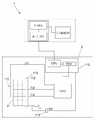
도 1은 본 발명의 바람직한 제1실시예를 나타내는 개략도이다.
도 2는 검사단계에서의 바람직한 제1실시예를 나타내는 개략도이다.
도 3은 본 발명에 따른 바람직한 제1실시예의 감지 모델을 나타내는 플로우차트이다.
도 4는 본 발명의 바람직한 제2실시예를 나타내는 개략도이다.
도 5는 본 발명의 바람직한 제3실시예를 나타내는 개략도이다.
도 6은 본 발명에 따른 바람직한 제3실시예의 감지 모델을 나타내는 플로우차트이다.
도 7은 본 발명의 바람직한 제4실시예를 나타내는 개략도이다.
도 8은 본 발명의 바람직한 제5실시예를 나타내는 개략도이다.1 is a schematic view showing a first preferred embodiment of the present invention.
2 is a schematic view showing a first preferred embodiment in the inspection step.
3 is a flowchart showing a sensing model of the first preferred embodiment according to the present invention.
4 is a schematic view showing a second preferred embodiment of the present invention.
5 is a schematic view showing a third preferred embodiment of the present invention.
Fig. 6 is a flowchart showing a sensing model of the third preferred embodiment according to the present invention.
7 is a schematic view showing a fourth preferred embodiment of the present invention.
8 is a schematic view showing a fifth preferred embodiment of the present invention.
공지된 종래 기술을 극복한 본 발명의 장점은 관련 도면과 함께 다음의 설명에 의해 당업자에게 더욱 자명하여질 것이다.Advantages of the invention overcoming known prior art will become more apparent to those skilled in the art by the following description in conjunction with the accompanying drawings.
더욱 상세하게 설명하기 전에, 유사한 구성요소들은 개시된 내용 전체에서 동일한 참조부호를 통해 나타내게 되는 것을 주목해야 한다.Before describing in more detail, it should be noted that like elements are represented by the same reference numerals throughout the disclosure.
도 1 및 도 2와 참조하여, 본 발명의 바람직한 제1실시예는 배터리(2)가 사용되는 동안에 다수의 배터리 셀들(21)의 정상적인 상태를 검사하기 위한 배터리 모니터링 시스템(1)을 보여준다. 상기 배터리 모니터링 시스템(1)은 감지기(detector)(11) 및 관리기(supervisor)(12)를 포함한다. 상기 감지기(11)는 적분기(integrator)(111), 및 상기 적분기(111)에 각각 연결된 다수의 센서들(113) 뿐만 아니라 중앙 프로세서(112)를 포함한다. 여기서, 상기 배터리 셀들(21)에 의해 발생된 온도 및 전압을 각각 감지하기 위해 상기 센서들(113)은 각각의 배터리 셀들(21)에 배치된다. 본 실시예에 따르면, 상기 배터리 셀(21)의 전압을 감지하기 위한 상기 센서(113)가 배터리 셀(21)에 연결 가능한 동안에, 상기 배터리 셀(21)의 온도를 감지하기 위한 상기 센서(113)는 상기 배터리 셀(21)에 접속되거나 접속될 수 없다. 상기 센서들(113)은 적분기(111)에 연결되어, 그에 따라 상기 적분기(111)는 배터리 셀(21)로부터 수신된 전압 신호와 온도 신호를 적분할 수 있고, 다음으로 상기 신호들을 상기 중앙 프로세서(112)에 전송할 수 있다.
1 and 2, the first preferred embodiment of the present invention shows a
전술한 바에 이어서, 상기 중앙 프로세서(112)는 컨버터(1121) 및 상기 컨버터(1121)에 연결된 중앙 처리 유닛(CPU,1122)을 포함한다. 상기 컨버터(1121)는 적분기(111)에 의해 적분된 배터리 셀(21)의 전압 신호 및 온도 신호를 수신하며, 별도의 전압 데이터 및 온도 데이터로 신호들 각각을 변환한다. 게다가, 상기 CPU(1122)는 그 내에 소정의 값을 저장하고, 상기 전압 데이터 및 온도 데이터를 소정의 값과 비교하여 결정을 하며, 따라서 비교된 결과가 달성된다.
Subsequent to the foregoing, the
상기 관리기(12)는 CPU(1122)로부터 비교된 결과를 수신하기 위한 컨트롤러(121)와, 상기 컨트롤러(121)에 연결된 디스플레이어(122)를 포함한다. 상기 컨트롤러(121)는 송수신 유닛(1211)을 경유하여 상기 CPU(1122)로부터 비교된 결과를 수신한다. 여기에, 상기 송수신 유닛(1211)은 무선 또는 유선으로 상기 CPU(1122)에 서로 연결된다. 본 실시예에 따르면, 송수신 유닛(1211)에 서로 유선으로 연결된 상기 CPU(1122)가 예시적으로 채택되었다. 또한, 상기 송수신 유닛(1211)는 상기 디스플레이어(122)에 더 연결되어 있는 처리 유닛(1212)에 연결된다. 그에 따라, 상기 CPU(1122)가 비교된 결과를 판단하고 임의의 비정상 상태를 수행하므로, 경고 신호가 상기 관리기(12)에서 내보내지고 상기 컨트롤러(121)를 경유하여 디스플레이어(122)에 디스플레이된다. 상기 경고 신호는 사용자에게 주의를 환기시켜 주기 위해 광범위하게 점멸 경고등, 버저(buzzer) 등을 채택할 수 있다. 상기 배터리(2) 내부의 정상적인 상태를 정확하게 나타내기 위해서, 상기 디스플레이어(122)는 본 실시예의 예시로서 스크린을 채택한다.
The
도 1 내지 도 3을 참조하여, 상기 배터리 모니터링 시스템(1)은 교통수단에 적용 가능하며, 상기 관리기(12)와 감지기(11)는 유선으로 연결된다. 즉, 상기 교통수단의 스크린(미도시)은 제어 회로(미도시)를 통해 배터리(2)에 유선으로 연결된 디스플레이어(122)에 제공되며, 상기 제어 회로는 컨트롤러(121)와 등가물이다. 사용상, 상기 교통수단은 전기를 제공하는 배터리(2)에 의해 구동된다. 동시에, 상기 센서들(113)은 각각의 온도 및 전압 신호들을 얻기 위한 상기 배터리(2) 내의 각각의 배터리 셀(21)의 정상적인 상태를 자유롭게 감지하기 위해 작동하며, 적분기(111)에 상기 신호들을 전송한다. 이로 인하여, 상기 적분기(111)가 감지된 온도 및 전압 신호들을 적분한 후, 상기 신호들은 상기 중앙 프로세서(112)의 컨버터(1121)에 더 전송된다. 그에 따라, 상기 신호들이 통신 데이터로 각각 변환되므로, 상기 CPU(1122)는 일관성 있는 분석을 하고 비교된 결과를 판단하기 위해 미리 결정된 값과 비교한다. 이러한 방법을 통해, 상기 컨트롤러(121)에 상기 비교된 결과가 전송된다. 따라서, 상기 송수신 장치(1211)는 비교된 결과를 수신한 다음, 각각의 배터리 셀(21)의 사용 상태를 나타낼 수 있는 디스플레이어(122)를 작동시키기 위해 처리 유닛(1212)에 비교된 결과를 전송한다. 따라서, 상기 비교된 결과가 비정상일 경우, 상기 CPU(1212)는 경고 신호를 즉시 내보내어 상기 처리 유닛(1212)가 점멸등이나 버저음을 내는 상기 디스플레이어(122)를 작동시킨다. 그러므로, 사용자들은 사용시에 배터리 셀(21)의 정상적인 상태를 인식할 수 있으며, 비정상적인 배터리(2)를 직접 변경시켜, 사용 편리성을 증대시킨다.
1 to 3, the
게다가, 교체된 배터리(2)가 재생되는 동안에, 상기 배터리(2) 내에서 파손된 배터리 셀들(21)의 일부만이 배터리(2)의 불충분한 전류 및 전압을 발생시킬 때, 재활용가는 손상된 상태의 상기 지정된 배터리 셀(21)을 단지 교체할 수 있다. 일반적으로, 상기한 문제를 해결할 수 있는 전형적인 방법은 모든 배터리(2)를 폐기하는 것이나, 이는 낭비가 우려된다. 본 발명에 의해 발명된 특징적인 구성에서, 상기 배터리 셀(21)의 교체는 상기 배터리(2)에 대한 오래 지속되는 사용수명 및 반복적인 이용을 가져오며, 이로 인해 오늘날의 환경 보호 개념과 일치한다.
In addition, while the replaced
도 4를 참조하여, 본 발명의 바람직한 제2실시예는 바람직한 제1실시예와 일관되는 구성요소들을 포함한다. 상기 배터리 셀(21)로부터 발생된 전류 신호를 감지하기 위해 각각의 배터리 셀(21)과 통신하도록 센서(113)가 추가적으로 설치된다. 그에 따라, 전압 신호 및 온도 신호를 감지하고 적분하는 것 외에 상기 감지된 전류 신호는 상기 센서(113)를 경유하여 중앙 프로세서(112)에 직접적으로 전송될 수 있다. 그래서, 상기 신호들은 변환, 구분, 및 분석을 통해 실행될 수 있다. 그러므로, 본 실시예에 따르면, 상기 센서들(113)은 배터리 셀(21)의 정상적인 상태를 판단할 수 있는 종합적인 해결책을 제공하여, 배터리(2)의 파손 상태를 판단하는 기준이 정확해진다.
Referring to Fig. 4, the second preferred embodiment of the present invention includes components consistent with the first preferred embodiment. The
도 5 및 도 6과 참조하여, 본 발명의 바람직한 제3실시예는 제1실시예와 동일한 요소를 구비한다. 그러나, 본 실시예에서는 상기 관리기(12)와 감지기(11)가 무선으로 연결된다; 즉, 상기 관리기(12)는 수동으로 채택한다. 상기 관리기(12)는 상기 CPU(1122)에 연결된 컨트롤러(121) 및 상기 컨트롤러(121)에 연결된 디스플레이어(122)를 여전히 가지고 있다. 사용상, 상기 적분기(111)는 센서(113)로부터 전송된 감지된 온도 및 전압 신호를 적분하고 나서, 상기 신호들을 변함없는 데이터로 변환시키기 위해 상기 동일 신호들을 컨버터(1121)에 전송한다. 그에 따라, 상기 CPU(1122)는 비교된 결과를 결정하기 위해 그 데이터를 구분하고, 비교하고, 그리고 분석하게 된다. 결과적으로, 상기 비교된 결과는 상기 컨트롤러(121)의 송수신 유닛(1211)에 무선으로 전송된다. 그래서, 상기 디스플레이어(122)는 상기 처리 유닛(1212)를 통해 비교된 결과에 대해 변함없는 정보를 나타낸다. 상기 비교된 결과가 비정상일 경우에, 상기 CPU(1212)는 경고 신호를 즉시 내보내어 상기 처리 유닛(1212)이 점멸등이나 버저음을 내는 상기 디스플레이어(122)를 작동시킨다. 그래서, 사용자들은 컨트롤러(121)를 통해 배터리 셀(21)의 정상적인 상태를 인식한다. 게다가, 손상된 배터리의 교체는 효과적일 수 있다. 그러므로 유지면에서 또는 외부 모니터링의 적용면에서 편리성을 증대시킨다.
5 and 6, the third preferred embodiment of the present invention has the same elements as the first embodiment. However, in this embodiment, the
도 7을 참조하여, 본 발명의 바람직한 제4실시예는 바람직한 제1 내지 제3실시예의 조합을 나타낸다. 상기 감지기(11) 및 관리기(12) 사이의 연결은 유선인 동시에 무선이다. 한편, 상기 감지기(11)가 교통수단(미도시)에 설치될 때, 상기 배터리(2)의 사용 상태는 유선방식을 통해 상기 교통수단의 디스플레이어(122)에 직접 표시될 수 있다. 그러므로, 사용자들은 사용중인 배터리 셀(21)의 전압, 온도, 그리고 전류 정보를 손쉽게 이해할 수 있다. 결과적으로, 임의의 배터리 셀(21)이 비정상인 경우에, 경고신호가 작동되며, 디스플레이어(122)에 디스플레이된다. 무선 수동 관리기(12')에 관하여, 이는 점검 및 유지보수에 적합하다. 이 방법에 따르면, 데이터의 판단, 비교, 그리고 분석을 나타내는 디스플레이어(122)는 설명할 수 있는 유일한 방법이 아니다; 또한, 사용자들은 관리기(12')의 디스플레이어(122') 상의 정보를 전부 직접 얻을 수 있고, 손상된 배터리(2) 또는 배터리 셀(21)의 대체 여부를 결정할 수 있다. 명백히, 상기 사용 편리성이 크게 향상된다.
Referring to Fig. 7, a fourth preferred embodiment of the present invention represents a combination of preferred first to third embodiments. The connection between the
도 8과 참조하여, 본 발명의 바람직한 제5실시예는 배터리 팩(A)이 배터리 모니터링 시스템(1)에 의해 모니터링되는 다수 배터리들(2)에 의해 형성되는 것을 나타낸다. 상기 배터리들(2)이 서로 직렬 또는 병렬로 연결되므로, 상기 배터리 팩(A)은 충분한 전기를 제공한다. 여기서, 후술할 설명은 예시로서 제4실시예에서 따른다. 다수의 배터리들(2)이 증가할 때, 상기 감지기(11)는 각각의 배터리(2)의 배터리 셀들(21)이 손상되었는지 감지하고 나서 상기 관리기(12) 상에 일관된 정보를 바람직하게 제공할 수 있다. 그러므로, 사용자들은 배터리들(2)의 정상적인 상태에 대한 정보를 신속히 얻을 수 있다. 그리고, 손상된 배터리(2) 또는 배터리 셀들(21)이 지체 없이 검사될 수 있으며 대체물을 선택할 수 있다.
Referring to FIG. 8, the fifth preferred embodiment of the present invention shows that the battery pack A is formed by a number of
이어서, 상기 배터리 모니터링 시스템(1)은 배터리(2)의 배터리 셀(21)에 대한 공동(omnibus) 검사를 개별적으로 실행하기 위해 상기 센서들(113)을 이용한다. 그러므로, 각각의 배터리 셀(21)에 설치된 각각의 센서들(113)은 완전하고 정확한 감지를 돕는다. 그리고, 사용자들은 사용하는 동안의 배터리 내의 변화를 완전히 알 수 있다. 따라서, 비정상적인 배터리 셀(21)만이 차후의 유지보수 및 교체를 지체 없이 선택할 수 있다. 그리고, 상기 배터리 셀(21) 중 단지 하나만이 손상된 경우, 모든 배터리(2) 또는 배터리 팩(A)을 변경할 필요가 없다. 그런 수단들은 긍정적으로 비용을 줄이고, 환경 오염을 줄인다. 그러므로, 본 발명은 배터리(2)의 정상적인 상태를 효과적으로 모니터링하고, 적용할 뿐만 아니라 설치 시의 편리성을 증대시키는 목적을 달성한다.
The
요약하면, 본 발명은 배터리 내의 각 배터리 셀의 정상적인 상태에 대해 종합적인 검사를 실행하기 위해 각각의 대응하는 배터리 셀 상에 설치된 센서들을 이용한다. 그래서, 사용자들은 각각의 배터리의 물리적인 상태를 자유롭게 이해할 수 있다. 그러므로, 조작 및 차후의 교체가 더욱 신속하고 편리해진다.
In summary, the present invention utilizes sensors installed on each corresponding battery cell to perform a comprehensive check on the normal state of each battery cell in the battery. Thus, users can freely understand the physical state of each battery. Therefore, the operation and subsequent replacement become faster and more convenient.
우리가 본 발명에 따른 실시예를 나타내고 설명하는 동안에, 본 발명의 범위로부터 벗어남 없이 추가적인 실시예가 만들어질 수 있는 것은 당업자에게 자명할 것이다.
While we show and describe embodiments according to the present invention, it will be apparent to those skilled in the art that additional embodiments may be made without departing from the scope of the present invention.
1 : 모니터링 시스템2 : 배터리
11 : 감지기12,12' : 관리기
111 : 적분기112 : 중앙 프로세서
113 : 센서121,121' : 컨트롤러
122,122' : 디스플레이어1121 : 컨버터
1122 : CPU1211 : 송수신 유닛
1212 : 처리 유닛1: monitoring system 2: battery
11:
111: integrator 112: central processor
113: sensor 121121 ': controller
122,122 ': Displayer 1121: Converter
1122: CPU 1211: transceiver unit
1212: Processing Unit
Claims (8)
Translated fromKorean상기 배터리(2)는 상기 모니터링 시스템(1)에 의해 모니터링된 다수의 배터리 셀들(21)에 의해 형성되고; 상기 모니터링 시스템(1)은 감지기(11) 및 상기 감지기(11)에 연결된 관리기(12)를 포함하고,
상기 배터리(2)에 배치된 상기 감지기(11)는 적분기(111), 및 상기 적분기(111)에 각각 연결된 다수의 센서들(113) 뿐만 아니라 중앙 프로세서(112)를 구비하고; 상기 센서들(113)은 전압 신호 및 온도 신호를 각각 감지하기 위해 상기 각각의 배터리 셀들(21)에 대응되게 배치되고; 상기 적분기(111)는 상기 중앙 프로세서(112)에 전압 및 온도 신호들을 적분하여 전송하고; 상기 중앙 프로세서(112)는 컨버터(1121) 및 상기 컨버터(1121)에 연결된 CPU(1122)를 포함하여, 상기 컨버터(1122)는 상기 신호들을 분리된 전압 및 온도 데이터로 변환시키기 위해 상기 적분기(111)로부터 전송된 상기 전압 및 온도 신호들을 수신하고; 상기 CPU(1122)는 상기 전압 및 온도 데이터를 비교하기 위해 소정 값을 저장하며; 상기 관리기는 상기 전압 데이터 및 상기 온도 데이터를 상기 소정 값과 비교하는 상기 CPU(1122)로부터의 비교된 결과를 디스플레이하기 위해 상기 CPU(1122)에 연결되고, 상기 CPU(1122)는 상기 비교된 결과의 불규칙한 상태에 우호적으로 작용하며, 경고를 지체 없이 수행하기 위해 상기 관리기(12)에 경고 신호를 내보내는 것을 특징으로 하는 배터리 모니터링 시스템.
In the battery monitoring system 1 for monitoring the normal state of the battery 2,
The battery (2) is formed by a plurality of battery cells (21) monitored by the monitoring system (1); The monitoring system 1 comprises a detector 11 and a manager 12 connected to the detector 11,
The detector (11) disposed in the battery (2) has an integrator (111) and a central processor (112) as well as a plurality of sensors (113) respectively connected to the integrator (111); The sensors (113) are disposed corresponding to the respective battery cells (21) for respectively sensing a voltage signal and a temperature signal; The integrator (111) integrates and transmits voltage and temperature signals to the central processor (112); The central processor 112 includes a converter 1121 and a CPU 1122 coupled to the converter 1121, so that the converter 1122 converts the signals into separate voltage and temperature data to the integrator 111. Receive the voltage and temperature signals transmitted from; The CPU 1122 stores a predetermined value for comparing the voltage and temperature data; The manager is coupled to the CPU 1122 to display the compared result from the CPU 1122 comparing the voltage data and the temperature data with the predetermined value, and the CPU 1122 is connected to the compared result. A battery monitoring system, which acts favorably on an irregular state of and sends a warning signal to the manager (12) to perform the warning without delay.
상기 배터리 셀(21)의 전류 신호를 더 감지하기 위해 센서(113)가 상기 각각의 배터리 셀(21) 상에 대응되게 설치되며, 상기 센서(113)에 의해 감지된 상기 전류 신호는 변환되고, 비교되며, 구분되도록 상기 중앙 프로세서(112)에 직접 전송되는 것을 특징으로 하는 배터리 모니터링 시스템.
The method of claim 1,
In order to further detect the current signal of the battery cell 21, a sensor 113 is installed correspondingly on each of the battery cells 21, and the current signal detected by the sensor 113 is converted, Battery monitoring system, characterized in that the comparison is directly sent to the central processor (112) to be distinguished.
상기 관리기(12)는 상기 CPU(1122)로부터 신호들을 수신하기 위한 컨트롤러(121), 및
상기 컨트롤러(121)에 연결된 디스플레이어(122)를 구비하는 것을 특징으로 하는 배터리 모니터링 시스템.
The method of claim 1,
The manager 12 is a controller 121 for receiving signals from the CPU 1122, and
Battery display system characterized in that it comprises a display (122) connected to the controller (121).
상기 컨트롤러(121)는 상기 CPU(1122)로부터 신호들을 수신하기 위한 송수신 유닛(1211), 및
상기 송수신 유닛(1211)에 연결된 처리 유닛(1212)을 갖는 것을 특징으로 하는 배터리 모니터링 시스템.
The method of claim 3,
The controller 121 is a transmission and reception unit 1211 for receiving signals from the CPU 1122, and
And a processing unit (1212) coupled to the transmit / receive unit (1211).
상기 디스플레이어(122)는 비정상적인 상태를 나타내기 위해 점멸 등을 채택하는 것을 특징으로 하는 배터리 모니터링 시스템.
The method of claim 3,
The display (122) is a battery monitoring system, characterized in that to adopt a flashing light to indicate an abnormal state.
다수의 배터리들(2)은 배터리 팩을 형성하고, 상기 배터리들(2)은 서로 연결된 것을 특징으로 하는 배터리 모니터링 시스템.
The method of claim 1,
A plurality of batteries (2) form a battery pack, wherein the batteries (2) are connected to each other.
다수의 배터리들(2)은 배터리 팩을 형성하고, 상기 배터리들(2)은 서로 연결된 것을 특징으로 하는 배터리 모니터링 시스템.
The method of claim 2,
A plurality of batteries (2) form a battery pack, wherein the batteries (2) are connected to each other.
다수의 배터리들(2)은 배터리 팩을 형성하고, 상기 배터리들(2)은 서로 연결된 것을 특징으로 하는 배터리 모니터링 시스템.The method of claim 3,
A plurality of batteries (2) form a battery pack, wherein the batteries (2) are connected to each other.
Priority Applications (1)
| Application Number | Priority Date | Filing Date | Title |
|---|---|---|---|
| KR1020100036241AKR101215037B1 (en) | 2010-04-20 | 2010-04-20 | Battery monitoring system |
Applications Claiming Priority (1)
| Application Number | Priority Date | Filing Date | Title |
|---|---|---|---|
| KR1020100036241AKR101215037B1 (en) | 2010-04-20 | 2010-04-20 | Battery monitoring system |
Publications (2)
| Publication Number | Publication Date |
|---|---|
| KR20110116680Atrue KR20110116680A (en) | 2011-10-26 |
| KR101215037B1 KR101215037B1 (en) | 2012-12-24 |
Family
ID=45030921
Family Applications (1)
| Application Number | Title | Priority Date | Filing Date |
|---|---|---|---|
| KR1020100036241AExpired - Fee RelatedKR101215037B1 (en) | 2010-04-20 | 2010-04-20 | Battery monitoring system |
Country Status (1)
| Country | Link |
|---|---|
| KR (1) | KR101215037B1 (en) |
Cited By (3)
| Publication number | Priority date | Publication date | Assignee | Title |
|---|---|---|---|---|
| KR20160041191A (en)* | 2014-10-07 | 2016-04-18 | 장진만 | Eco-friendly electric cultivator using HBSR Dual Motor |
| KR20200000793U (en)* | 2018-10-11 | 2020-04-21 | 한국전력공사 | Apparatus for extending the life of lithium battery and performing remote failure test |
| KR20210055313A (en)* | 2019-11-07 | 2021-05-17 | 송과모터스 주식회사 | Protecting method for battery pack and apparatus thereof |
Families Citing this family (1)
| Publication number | Priority date | Publication date | Assignee | Title |
|---|---|---|---|---|
| KR101989491B1 (en) | 2015-11-30 | 2019-06-14 | 주식회사 엘지화학 | Apparatus method for defect detecting of the battery cell by unknown discharge current |
Family Cites Families (1)
| Publication number | Priority date | Publication date | Assignee | Title |
|---|---|---|---|---|
| US7589532B2 (en) | 2005-08-23 | 2009-09-15 | Lg Chem, Ltd. | System and method for estimating a state vector associated with a battery |
- 2010
- 2010-04-20KRKR1020100036241Apatent/KR101215037B1/ennot_activeExpired - Fee Related
Cited By (3)
| Publication number | Priority date | Publication date | Assignee | Title |
|---|---|---|---|---|
| KR20160041191A (en)* | 2014-10-07 | 2016-04-18 | 장진만 | Eco-friendly electric cultivator using HBSR Dual Motor |
| KR20200000793U (en)* | 2018-10-11 | 2020-04-21 | 한국전력공사 | Apparatus for extending the life of lithium battery and performing remote failure test |
| KR20210055313A (en)* | 2019-11-07 | 2021-05-17 | 송과모터스 주식회사 | Protecting method for battery pack and apparatus thereof |
Also Published As
| Publication number | Publication date |
|---|---|
| KR101215037B1 (en) | 2012-12-24 |
Similar Documents
| Publication | Publication Date | Title |
|---|---|---|
| US20110130983A1 (en) | Battery monitoring system | |
| KR102448292B1 (en) | battery pack diagnostic device | |
| KR101439399B1 (en) | Monitor for optical fiber composite cable in power transmission or supply of electric power or transformation of electric power | |
| US10360789B2 (en) | Fire notification system and test method using test jig therefor | |
| KR101225055B1 (en) | Apparrutus and method to inspect obstruction light for flight, and system using thereof | |
| CN112858935B (en) | Battery pack thermal runaway early warning method and device, battery pack and electric equipment | |
| KR20120071850A (en) | System and method for monitoring underground transmission line | |
| KR102124003B1 (en) | A power system for camping-trailer and controlling method | |
| US20230258726A1 (en) | Battery pack safety monitor | |
| CN108923533B (en) | Emergency starting power supply with communication function and monitoring system thereof | |
| CN104349560B (en) | Fault detection device for street lamp lighting system and operation method thereof | |
| KR101215037B1 (en) | Battery monitoring system | |
| CN103490108A (en) | Novel safety management method and device for power battery pack of electric vehicle | |
| CN116131412A (en) | Mobile power supply charge-discharge abnormity alarm system | |
| CN110844732A (en) | Intelligent monitoring management system for elevator fault testing | |
| KR20150047649A (en) | Management System For Battery Using Emergency Power Supply | |
| KR20210120927A (en) | An electrical safety evaluting device for operating ess | |
| CN107688152A (en) | A kind of shared sun-rain umbrella frame warning system | |
| KR101138576B1 (en) | A diagnosis apparatus for battery | |
| KR101003181B1 (en) | Electric power monitoring system and power monitoring method | |
| CN108973764A (en) | A kind of charging unit and the detection method for early warning that charges | |
| EP0928126B1 (en) | Method and arrangement for observing the operational status of an electrical device | |
| CN113238105A (en) | Cab signal vehicle-mounted equipment detection system and detection device thereof, and installation mode and detection method of detection system | |
| JP2021092984A (en) | Remote monitoring system for emergency charging and discharging devices | |
| CN107221717A (en) | The protection device and method of electrokinetic cell |
Legal Events
| Date | Code | Title | Description |
|---|---|---|---|
| A201 | Request for examination | ||
| PA0109 | Patent application | St.27 status event code:A-0-1-A10-A12-nap-PA0109 | |
| PA0201 | Request for examination | St.27 status event code:A-1-2-D10-D11-exm-PA0201 | |
| E902 | Notification of reason for refusal | ||
| PE0902 | Notice of grounds for rejection | St.27 status event code:A-1-2-D10-D21-exm-PE0902 | |
| P11-X000 | Amendment of application requested | St.27 status event code:A-2-2-P10-P11-nap-X000 | |
| P13-X000 | Application amended | St.27 status event code:A-2-2-P10-P13-nap-X000 | |
| PG1501 | Laying open of application | St.27 status event code:A-1-1-Q10-Q12-nap-PG1501 | |
| PE0902 | Notice of grounds for rejection | St.27 status event code:A-1-2-D10-D21-exm-PE0902 | |
| P11-X000 | Amendment of application requested | St.27 status event code:A-2-2-P10-P11-nap-X000 | |
| P13-X000 | Application amended | St.27 status event code:A-2-2-P10-P13-nap-X000 | |
| E701 | Decision to grant or registration of patent right | ||
| PE0701 | Decision of registration | St.27 status event code:A-1-2-D10-D22-exm-PE0701 | |
| R17-X000 | Change to representative recorded | St.27 status event code:A-3-3-R10-R17-oth-X000 | |
| GRNT | Written decision to grant | ||
| PR0701 | Registration of establishment | St.27 status event code:A-2-4-F10-F11-exm-PR0701 | |
| PR1002 | Payment of registration fee | St.27 status event code:A-2-2-U10-U11-oth-PR1002 Fee payment year number:1 | |
| PG1601 | Publication of registration | St.27 status event code:A-4-4-Q10-Q13-nap-PG1601 | |
| FPAY | Annual fee payment | Payment date:20151123 Year of fee payment:4 | |
| PR1001 | Payment of annual fee | St.27 status event code:A-4-4-U10-U11-oth-PR1001 Fee payment year number:4 | |
| R17-X000 | Change to representative recorded | St.27 status event code:A-5-5-R10-R17-oth-X000 | |
| FPAY | Annual fee payment | Payment date:20160811 Year of fee payment:5 | |
| PR1001 | Payment of annual fee | St.27 status event code:A-4-4-U10-U11-oth-PR1001 Fee payment year number:5 | |
| P22-X000 | Classification modified | St.27 status event code:A-4-4-P10-P22-nap-X000 | |
| FPAY | Annual fee payment | Payment date:20170714 Year of fee payment:6 | |
| PR1001 | Payment of annual fee | St.27 status event code:A-4-4-U10-U11-oth-PR1001 Fee payment year number:6 | |
| PR1001 | Payment of annual fee | St.27 status event code:A-4-4-U10-U11-oth-PR1001 Fee payment year number:7 | |
| PR1001 | Payment of annual fee | St.27 status event code:A-4-4-U10-U11-oth-PR1001 Fee payment year number:10 | |
| P22-X000 | Classification modified | St.27 status event code:A-4-4-P10-P22-nap-X000 | |
| PR1001 | Payment of annual fee | St.27 status event code:A-4-4-U10-U11-oth-PR1001 Fee payment year number:11 | |
| PR1001 | Payment of annual fee | St.27 status event code:A-4-4-U10-U11-oth-PR1001 Fee payment year number:12 | |
| PC1903 | Unpaid annual fee | St.27 status event code:A-4-4-U10-U13-oth-PC1903 Not in force date:20241218 Payment event data comment text:Termination Category : DEFAULT_OF_REGISTRATION_FEE | |
| PC1903 | Unpaid annual fee | St.27 status event code:N-4-6-H10-H13-oth-PC1903 Ip right cessation event data comment text:Termination Category : DEFAULT_OF_REGISTRATION_FEE Not in force date:20241218 |