KR20110113931A - Apparatus and method for operating a touch screen panel of a mobile terminal - Google Patents
Apparatus and method for operating a touch screen panel of a mobile terminalDownload PDFInfo
- Publication number
- KR20110113931A KR20110113931AKR1020100033281AKR20100033281AKR20110113931AKR 20110113931 AKR20110113931 AKR 20110113931AKR 1020100033281 AKR1020100033281 AKR 1020100033281AKR 20100033281 AKR20100033281 AKR 20100033281AKR 20110113931 AKR20110113931 AKR 20110113931A
- Authority
- KR
- South Korea
- Prior art keywords
- terminal
- voltage
- touch screen
- screen panel
- processor
- Prior art date
- Legal status (The legal status is an assumption and is not a legal conclusion. Google has not performed a legal analysis and makes no representation as to the accuracy of the status listed.)
- Withdrawn
Links
Images


Classifications
- G—PHYSICS
- G06—COMPUTING OR CALCULATING; COUNTING
- G06F—ELECTRIC DIGITAL DATA PROCESSING
- G06F3/00—Input arrangements for transferring data to be processed into a form capable of being handled by the computer; Output arrangements for transferring data from processing unit to output unit, e.g. interface arrangements
- G06F3/01—Input arrangements or combined input and output arrangements for interaction between user and computer
- G06F3/03—Arrangements for converting the position or the displacement of a member into a coded form
- G06F3/041—Digitisers, e.g. for touch screens or touch pads, characterised by the transducing means
- G06F3/045—Digitisers, e.g. for touch screens or touch pads, characterised by the transducing means using resistive elements, e.g. a single continuous surface or two parallel surfaces put in contact
- G—PHYSICS
- G06—COMPUTING OR CALCULATING; COUNTING
- G06F—ELECTRIC DIGITAL DATA PROCESSING
- G06F11/00—Error detection; Error correction; Monitoring
- G06F11/07—Responding to the occurrence of a fault, e.g. fault tolerance
- G—PHYSICS
- G06—COMPUTING OR CALCULATING; COUNTING
- G06F—ELECTRIC DIGITAL DATA PROCESSING
- G06F3/00—Input arrangements for transferring data to be processed into a form capable of being handled by the computer; Output arrangements for transferring data from processing unit to output unit, e.g. interface arrangements
- G06F3/01—Input arrangements or combined input and output arrangements for interaction between user and computer
- G06F3/03—Arrangements for converting the position or the displacement of a member into a coded form
- G06F3/041—Digitisers, e.g. for touch screens or touch pads, characterised by the transducing means
- G06F3/0416—Control or interface arrangements specially adapted for digitisers
- G06F3/04164—Connections between sensors and controllers, e.g. routing lines between electrodes and connection pads
Landscapes
- Engineering & Computer Science (AREA)
- Theoretical Computer Science (AREA)
- General Engineering & Computer Science (AREA)
- Physics & Mathematics (AREA)
- General Physics & Mathematics (AREA)
- Human Computer Interaction (AREA)
- Quality & Reliability (AREA)
- Computer Networks & Wireless Communication (AREA)
- Telephone Function (AREA)
- Position Input By Displaying (AREA)
Abstract
Translated fromKorean
Description
Translated fromKorean본 발명은 휴대 단말기의 터치스크린 패널 운용 장치 및 방법에 관한 것으로서, 특히, 저항 막 방식의 터치스크린 패널을 구비하는 휴대 단말기에 있어서, 사용자가 의도하지 않게 터치스크린 패널이 장시간 눌려짐으로 인해 발생할 수 있는 터치스크린 패널의 고장을 방지하기 위한 터치스크린 패널 운용 장치 및 방법에 관한 것이다.The present invention relates to an apparatus and method for operating a touch screen panel of a portable terminal, and particularly, to a portable terminal having a resistive touch screen panel, which may be caused by a user unintentionally pressing the touch screen panel for a long time. The present invention relates to a touch screen panel operating apparatus and method for preventing a failure of a touch screen panel.
터치스크린 패널(touch screen panel)은 디스플레이 장치의 표면에 장착되어 사용자의 손가락, 터치 펜 등의 물리적 접촉을 전기적 신호로 변환하여 출력하는 장치로서, 액정표시장치(liquid crystal display), 플라즈마 디스플레이 패널(plasma display panel), EL(electro-luminescence) 소자 등에 응용되고 있다.A touch screen panel is a device mounted on the surface of a display device to convert physical contact of a user's finger, touch pen, etc. into an electrical signal and output the electrical signal. A liquid crystal display, a plasma display panel ( It is applied to plasma display panels (EL) and electroluminescent (EL) devices.
이와 같은 터치스크린 패널은 동작 원리에 따라 크게 정전용량 방식(capacitive), 저항 막 방식(resistive), 초음파 방식(ultrasonic wave), 적외선 방식(infra-red) 등으로 구분되는데, 이 중 저항 막 방식은 현재 출시된 휴대 단말기에 널리 사용되고 있는 방식이다.Such touch screen panels are classified into capacitive, resistive, ultrasonic wave, and infrared-red according to the principle of operation. It is widely used in currently released portable terminals.
저항 막 방식의 터치스크린 패널은 일반적으로 도 1에 도시된 바와 같이 상부기판(110)과 하부기판(120)의 조합으로 이루어지며, 하부기판(120) 상에는 상부기판(110)과 하부기판(120)의 간격을 유지하기 위한 도트 스페이서(dot spacer)(130)가 일정 간격을 두고 구비된다. 또한, 상부기판(110)과 하부기판(120)은 접착제(140)를 매개로 결합되며, 상부기판(110)과 하부기판(120) 각각은 절연기판(111)(121) 및 ITO(Indium Tin Oxide)(112)(122)로 구성된다. 이와 같은 구조 하에서, 외부의 물리적 힘이 상부기판(110) 상에 인가되어 상부기판(110)의 ITO(112)가 하부기판(120)의 ITO(122)와 접촉되면, 터치스크린 패널을 구비하는 장치는 해당 접촉 지점의 X축 및 Y축 좌표를 인식하여 터치 위치를 파악한다.The resistive touch screen panel is generally made of a combination of the
그런데 예를 들어, 사용자가 휴대 단말기를 바지 뒷주머니에 넣고 앉는 경우, 사용자가 의도하지 않게 터치스크린 패널에 지속적으로 압력이 가해질 수 있다. 장시간 동안 터치스크린 패널에 지속적으로 압력이 가해지는 경우, 상부기판(110)의 ITO(112)와 하부기판(120)의 ITO(122) 사이의 간격이 유지되지 못할 수 있으며, 이는 터치스크린 패널의 오작동 및 불량으로 이어질 수 있다.However, for example, when the user sits with the portable terminal in the back pocket of the pants, the user may inadvertently apply pressure to the touch screen panel. When the pressure is continuously applied to the touch screen panel for a long time, the gap between the ITO 112 of the
본 발명의 목적은 이와 같이 장시간 동안 터치스크린 패널에 지속적인 압력이 가해짐으로 인해 발생할 수 있는 터치스크린 패널의 오작동과 불량을 방지하기 위한 터치스크린 패널 운용 장치 및 방법을 제공하는데 있다.An object of the present invention is to provide an apparatus and method for operating a touch screen panel to prevent malfunction and failure of the touch screen panel that can be caused by the continuous pressure is applied to the touch screen panel for a long time.
본 발명의 실시예에 따른 휴대 단말기는 제1단자와 제2단자를 구비하며, 터치 입력 시, 상기 제1단자와 제2단자 사이에 저항을 생성하는 터치스크린 패널; 일단이 상기 제1단자와 연결되고 다른 일단이 전원부 및 프로세서와 연결되는 제1스위치; 일단이 상기 제2단자와 연결되고 다른 일단이 접지되는 제2스위치; 상기 제1스위치 및 프로세서와 연결되며, 전압을 생성하는 전원부; 진동 또는 사운드를 출력하는 출력부; 및 슬립 모드(sleep mode) 진입 시, 상기 제1스위치 및 제2스위치를 닫으며, 상기 제1스위치와의 연결 단자에서 전압을 측정하고, 전압이 변경되는 경우 변경된 전압이 유지되는 시간을 측정하고, 측정된 시간이 기 설정된 임계 시간 이상에 해당하는 경우, 상기 출력부를 제어하여 진동 또는 사운드를 출력하는 프로세서를 포함하는 것을 특징으로 한다.A mobile terminal according to an embodiment of the present invention includes a touch screen panel having a first terminal and a second terminal and generating a resistance between the first terminal and the second terminal when a touch is input; A first switch having one end connected to the first terminal and the other end connected to a power supply and a processor; A second switch having one end connected to the second terminal and the other end grounded; A power supply unit connected to the first switch and the processor and generating a voltage; An output unit for outputting vibration or sound; And closing the first switch and the second switch when entering a sleep mode, measuring a voltage at a connection terminal with the first switch, and measuring a time for which the changed voltage is maintained when the voltage is changed. The controller may include a processor configured to output the vibration or sound by controlling the output unit when the measured time corresponds to a preset threshold time or more.
본 발명의 실시예에 따른 터치스크린 패널 운용 방법은 제1단자와 제2단자를 구비하는 터치스크린 패널, 일단이 상기 제1단자와 연결되고 다른 일단이 전원부 및 프로세서와 연결되는 제1스위치, 일단이 상기 제2단자와 연결되고 다른 일단이 접지되는 제2스위치, 상기 제1스위치 및 프로세서와 연결되며 전압을 생성하는 전원부를 포함하는 휴대 단말기의 터치스크린 패널 운용 방법에 있어서, 슬립 모드(sleep mode) 진입 시, 제1스위치 및 제2스위치를 닫는 단계; 상기 제1스위치와의 연결 단자에서 전압을 측정하는 단계; 상기 측정된 전압이 변경되는지 여부를 판단하는 단계; 상기 측정된 전압이 변경되는 경우, 변경된 전압이 유지되는 시간을 측정하는 단계; 및 상기 측정된 시간이 기 설정된 임계 시간 이상에 해당하는 것으로 판단하면, 진동 또는 사운드를 출력하는 단계를 포함하는 것을 특징으로 한다.A touch screen panel operating method according to an embodiment of the present invention includes a touch screen panel having a first terminal and a second terminal, a first switch having one end connected to the first terminal and the other end connected to a power supply and a processor. In the method of operating a touch screen panel of a mobile terminal comprising a second switch connected to the second terminal and the other end is grounded, the first switch and a processor and a power unit for generating a voltage, a sleep mode Closing the first switch and the second switch upon entry; Measuring a voltage at a connection terminal with the first switch; Determining whether the measured voltage is changed; Measuring a time for which the changed voltage is maintained when the measured voltage is changed; And if it is determined that the measured time corresponds to a preset threshold time or more, outputting a vibration or a sound.
터치스크린 패널에 지속적인 압력이 가해지는 상황을 사용자에게 알림으로써, 터치스크린 패널의 오작동과 불량의 발생을 미리 방지할 수 있으며, 터치스크린 패널을 보호할 수 있다. 이로 인해, 추후 생기게 되는 수리비용의 발생을 줄일 수 있고, 사업자 입장에서는 서비스 비용의 발생을 줄일 수 있다.By notifying the user of a situation in which the pressure is continuously applied to the touch screen panel, the touch screen panel can be prevented from malfunctioning and defects in advance, and the touch screen panel can be protected. As a result, it is possible to reduce the occurrence of repair costs in the future, and it is possible to reduce the occurrence of service costs for the operator.
도 1은 일반적인 저항 막 방식의 터치스크린 패널의 구성을 나타내는 도면이다.
도 2는 본 발명의 실시예에 따른 터치스크린 패널을 구비하는 휴대 단말기의 내부 구성도에 해당한다.
도 3a는 본 발명의 실시예에 따른 터치스크린 패널의 구성을 도시하는 도면이다.
도 3b 및 도 3c는 본 발명의 실시예에 따른 터치스크린 패널의 동작 원리를 도시하는 도면이다.
도 4는 본 발명의 실시예에 따른 휴대 단말기의 제어부의 구성 요소들을 구체적으로 도시한 도면에 해당한다.
도 5는 본 발명의 실시예에 따른 터치스크린 패널에 지속적인 압력이 가해지고 있음을 사용자에게 알리기 위한 터치스크린 패널의 운용 방법을 나타내는 순서도이다.
도 6은 본 발명의 실시예에 따른 제어부의 구성 요소들을 나타내는 도면으로서, 제1스위치와 제2스위치가 닫힌 형태를 도시하는 도면이다.1 is a diagram illustrating a configuration of a general resistive touch screen panel.
2 is an internal configuration diagram of a mobile terminal having a touch screen panel according to an embodiment of the present invention.
3A is a diagram illustrating a configuration of a touch screen panel according to an embodiment of the present invention.
3B and 3C illustrate an operating principle of a touch screen panel according to an exemplary embodiment of the present invention.
4 is a diagram illustrating in detail the components of the control unit of the mobile terminal according to an embodiment of the present invention.
5 is a flowchart illustrating a method of operating a touch screen panel for notifying a user that continuous pressure is applied to the touch screen panel according to an exemplary embodiment of the present invention.
FIG. 6 is a diagram illustrating components of a control unit according to an exemplary embodiment of the present invention, in which the first switch and the second switch are closed.
이하, 본 발명에 따른 바람직한 실시 예를 첨부한 도면을 참조하여 상세히 설명하기로 한다. 하기 설명은 본 발명의 실시 예에 따른 동작을 이해하는데 필요한 부분만을 설명하며, 그 이외 부분의 설명은 본 발명의 요지를 흩뜨리지 않도록 생략될 것이라는 것을 유의하여야 한다.Hereinafter, exemplary embodiments of the present invention will be described in detail with reference to the accompanying drawings. It should be noted that the following description describes only those parts necessary for understanding the operation according to the embodiment of the present invention, and descriptions of other parts will be omitted so as not to distract from the gist of the present invention.
이하에서 설명되는 본 명세서 및 청구범위에 사용된 용어나 단어는 통상적이거나 사전적인 의미로 한정해서 해석되어서는 아니 되며, 발명자는 그 자신의 발명을 가장 최선의 방법으로 설명하기 위해 용어의 개념을 적절하게 정의할 수 있다는 원칙에 입각하여 본 발명의 기술적 사상에 부합하는 의미와 개념으로 해석되어야만 한다. 따라서 본 명세서에 기재된 실시 예와 도면에 도시된 구성은 본 발명의 가장 바람직한 일 실시예에 불과할 뿐이고, 본 발명의 기술적 사상을 모두 대변하는 것은 아니므로, 본 출원시점에 있어서 이들을 대체할 수 있는 다양한 균등물과 변형 예들이 있을 수 있음을 이해하여야 한다.The terms or words used in the specification and claims described below should not be construed as being limited to the ordinary or dictionary meanings, and the inventors should properly introduce the concept of terms in order to explain their invention in the best way. It should be interpreted as meanings and concepts in accordance with the technical spirit of the present invention based on the principle that it can be defined. Therefore, the embodiments described in the present specification and the configuration shown in the drawings are only the most preferred embodiments of the present invention, and do not represent all of the technical ideas of the present invention, and various alternatives may be substituted at the time of the present application. It should be understood that there may be equivalents and variations.
즉, 본 발명의 실시 예에 따른 상기 휴대 단말기는 저항 막 방식의 터치스크린 패널을 포함하는 단말기로서, 바람직하게는 이동통신 단말기, 이동 전화기, 개인 정보 단말기(PDA, Personal Digital Assistant), 스마트 폰(Smart Phone), IMT-2000(International Mobile Telecommunication 2000) 단말기, CDMA(Code Division Multiple Access) 단말기, WCDMA(Wideband Code Division Multiple Access) 단말기, GSM(Global System for Mobile communication) 단말기, GPRS(General Packet Radio Service) 단말기, EDGE(Enhanced Data GSM Evironment) 단말기, UMTS(Universal Mobile Telecommunication Service) 단말기 및 디지털 방송(Digital Broadcasting) 단말기, ATM(Automated Teller Machine) 등과 같은 모든 정보통신기기 및 멀티미디어 기기와, 그에 대한 응용에도 적용될 수 있음은 자명할 것이다.That is, the portable terminal according to the embodiment of the present invention is a terminal including a resistive touch screen panel, and preferably, a mobile communication terminal, a mobile phone, a personal digital assistant (PDA), a smart phone ( Smart Phone (IMT-2000), International Mobile Telecommunication 2000 (IMT-2000) terminal, Code Division Multiple Access (CDMA) terminal, Wideband Code Division Multiple Access (WCDMA) terminal, Global System for Mobile communication (GSM) terminal, General Packet Radio Service ) All information communication and multimedia devices such as terminals, EDGE (Enhanced Data GSM Evironment) terminals, Universal Mobile Telecommunication Service (UMTS) terminals, digital broadcasting (Digital Broadcasting) terminals, automated teller machines (ATMs), and applications thereof. It will be obvious that it can be applied.
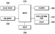
도 2는 본 발명의 실시예에 따른 터치스크린 패널을 구비하는 휴대 단말기(200)의 내부 구성도에 해당한다. 휴대 단말기(200)는 터치스크린 패널(touch screen panel, 210), 오디오 처리부(220), 진동 출력부(230), 저장부(240), 표시부(250), 키 입력부(260) 및 제어부(270)를 포함한다.2 is a diagram illustrating an internal configuration of a portable terminal 200 having a touch screen panel according to an exemplary embodiment of the present invention. The mobile terminal 200 includes a
터치스크린 패널(210)은 저항 막 방식의 터치스크린 패널에 해당하는 것이 바람직하며, 터치스크린 패널(210)의 구성은 도 3a에 구체적으로 도시되어 있다.The
도 3a는 본 발명의 실시예에 따른 터치스크린 패널(210)의 구성을 도시하는 도면이다.3A is a diagram illustrating a configuration of a
도 3a를 참조하면, 터치스크린 패널(210)은 X축 양(+)단자(10)와 음(-)단자(11)를 포함하는 상부기판(211), Y축 양(+)단자(20)와 음(-)단자(21)를 포함하는 하부기판(212), 상기 상부기판(211)과 상기 하부기판(212)을 분리하는 도트 스페이서(Dot Spacer, 30)를 포함한다. 이외에도 터치스크린 패널(210)은 상기 상부기판(211)을 보호하는 커버(미도시), 상기 상부기판(211)과 상기 하부기판(212)을 접착하는 접착제(미도시) 및 아날로그 신호를 디지털 신호를 변화하는 ADC(Analog Digital Converter)를 더 포함할 수 있다. 또한 상부기판(211)과 하부기판(212) 각각은 절연기판 및 ITO(Indium Tin Oxide)로 구성될 수 있다. 본 발명의 실시예에 따른 터치스크린 패널(210)의 동작 원리는 도 3b 및 도 3c에 구체적으로 도시되어 있다.Referring to FIG. 3A, the
도 3b 및 도 3c는 본 발명의 실시예에 따른 터치스크린 패널(210)의 동작 원리를 도시하는 도면이다.3B and 3C illustrate an operating principle of the
도 3a를 함께 참조하여 설명하면, 상부기판(211) 또는 하부기판(212)의 양단에 일정한 전류를 흘려주면 상기 전류가 흐르는 기판이 저항 성분을 갖는 저항체와 함께 작용하기 때문에 기판 양단에 전압이 걸리게 된다. 이 후, 손 또는 펜 등의 입력도구로 터치스크린 패널(210)에 접촉을 입력하게 되면 상부기판(211)이 휘어지면서 하부기판(212)과 접촉하게 된다. 이 때, 두 기판(상부기판(211)과 하부기판(212))의 저항 성분은 병렬 접속 형태가 되어, 저항 값의 변화가 일어나게 되며, 기판 양단에 흐르는 전류에 의하여 전압의 변화도 일어나게 된다. 휴대 단말기(200)는 이러한 전압의 변화 정도로서 접촉된 지점의 좌표를 인식하게 된다.Referring to FIG. 3A, when a constant current flows through both ends of the
터치스크린 패널(210)에 터치가 입력되지 않는 경우, 터치스크린 패널(210)은 도 3b에 도시된 바와 같이 상부기판(211)과 하부기판(212)이 각각의 제2저항(이하 'R2') 및 제3저항(이하 'R3')에 해당하는 저항 성분을 포함하는 것으로 나타낼 수 있다. 이러한 상황에서, 사용자에 의해 터치스크린 패널(210)에 터치가 입력되는 경우, 터치스크린 패널(210)은 도 3c에 나타낸 바와 같이 터치된 지점(C)에서 상부기판(211)과 하부기판(212)이 서로 접촉되어 제4저항(이하 'R4'), 제5저항(이하 'R5'), 제6저항(이하 'R6'), 제7저항(이하 'R7')을 갖는 회로로 표현될 수 있다.When a touch is not input to the
여기서, R4는 X축 양(+)단자와 터치된 지점(C) 사이의 저항성분이고, R5는 X축 음(-)단자와 터치된 지점(C) 사이의 저항성분이며, R6은 Y축 양(+)단자와 터치된 지점(C) 사이의 저항성분이고, R7은 Y축 음(-)단자와 터치된 지점(C) 사이의 저항성분에 해당하며, 각 저항 값은 터치된 지점(C)에 따라 가변될 수 있다.Here, R4 is a resistance component between the X-axis positive (+) terminal and the touched point (C), R5 is a resistance component between the X-axis negative (-) terminal and the touched point (C), R6 is a Y-axis positive The resistance component between the positive terminal and the touched point (C), R7 corresponds to the resistance component between the negative Y-axis terminal and the touched point (C), and each resistance value is the touched point (C). It can vary according to.
즉, 사용자에 의해 터치스크린 패널(210)에 터치가 입력되지 않는 경우, 상부기판(211)에는 R2, 하부기판(212)에는 R3의 저항 성분만이 존재하기 때문에 X축의 단자(양(+)단자 또는 음(-)단자)와 Y축의 단자(양(+)단자 또는 음(-)단자) 사이에는 저항 성분이 존재하지 않는다. 그러나 사용자에 의해 터치스크린 패널(210)에 터치가 입력되는 경우, 터치된 지점(C)을 중심으로 X축의 양(+)단자, X축의 음(-)단자, Y축의 양(+)단자 및 Y축의 음(-)단자 사이에 저항 성분(R4, R5, R6 및 R7)이 생성되기 때문에, X축의 단자(양(+)단자 또는 음(-)단자)와 Y축의 단자(양(+)단자 또는 음(-)단자) 사이에도 저항 성분이 생성된다.That is, when a touch is not input to the
터치스크린 패널(210)의 X축의 양(+)단자, X축의 음(-)단자, Y축의 양(+)단자 및 Y축의 음(-)단자는 제어부(270) 내의 프로세서(processor)(271)와 연결된다. 본 발명의 실시예에 따라 휴대 단말기(200)는 TSP 드라이버(Touch Screen Panel Driver)(미도시)를 더 포함할 수 있으며, 터치스크린 패널(210)은 TSP 드라이버를 통해 프로세서(276)와 연결될 수 있다. TSP 드라이버는 X축의 양(+)단자, X축의 음(-)단자, Y축의 양(+)단자 및 Y축의 음(-)단자의 출력 전압을 이용하여 터치스크린 패널(210)에서 사용자로부터 터치가 입력된 지점의 좌표를 연산하는 역할을 수행한다.The positive terminal of the X-axis, the negative terminal of the X-axis, the positive terminal of the Y-axis, and the negative terminal of the Y-axis of the
예를 들어, 도 3c를 참조할 때, X축 양(+)단자에 구동전압(Vcc)을 인가하고, X축 음(-)단자를 접지하고, Y축의 양(+)단자 및 Y축의 음(-)단자의 출력 전압을 측정하면, Y축의 양(+)단자 및 Y축의 음(-)단자의 출력 전압은 Vcc*(R4/R4+R5)로 측정된다. R4의 크기는 X축 양(+)단자와 터치된 지점(C)과의 거리에 비례하기 때문에, Y축의 양(+)단자 또는 음(-)단자의 전압 값을 확인하면 터치된 지점(C)의 X좌표를 확인할 수 있다. 동일한 방법으로 Y축 양(+)단자에 구동전압(Vcc)을 인가하고, Y축 음(-)단자를 접지하고, X축의 양(+)단자 및 X축의 음(-)단자의 출력 전압을 측정하면, X축의 양(+)단자 및 X축의 음(-)단자의 출력 전압은 Vcc*(R6/R6+R7)로 측정되며, R6의 크기는 Y축 양(+)단자와 터치된 지점(C)과의 거리에 비례하기 때문에 상기 측정된 값을 통해 터치된 지점(C)의 Y좌표를 확인할 수 있게 된다. 본 발명의 실시예에 따른 휴대 단말기(200)는 TSP 드라이버가 제어부(270) 내에 포함되도록 구성될 수 있으며, 터치스크린 패널(210)과 TSP 드라이버가 결합하여 터치스크린 패널부를 형성하는 형태로 구성될 수 있다.For example, referring to FIG. 3C, the driving voltage Vcc is applied to the X-axis positive terminal, the X-axis negative terminal is grounded, the positive terminal of the Y-axis, and the negative of the Y-axis. When the output voltage of the negative terminal is measured, the output voltage of the positive terminal of the Y axis and the negative terminal of the Y axis is measured as Vcc * (R4 / R4 + R5). Since the magnitude of R4 is proportional to the distance between the positive (+) terminal of the X axis and the touched point (C), when the voltage value of the positive (+) terminal or the negative (-) terminal of the Y axis is checked, the touched point (C) You can check the X coordinate of). In the same way, the driving voltage (Vcc) is applied to the Y-axis positive terminal, the Y-axis negative terminal is grounded, and the output voltage of the positive terminal of the X-axis and the negative terminal of the X-axis is In measurement, the output voltage of the positive terminal of the X axis and the negative terminal of the X axis is measured by Vcc * (R6 / R6 + R7), and the magnitude of R6 is the point where the positive terminal of the X axis is touched. Since it is proportional to the distance to (C), it is possible to check the Y coordinate of the touched point (C) through the measured value. The mobile terminal 200 according to the embodiment of the present invention may be configured such that the TSP driver is included in the
오디오 처리부(220)는 코덱(CODEC)을 포함할 수 있으며, 코덱은 패킷 데이터 등을 처리하는 데이터 코덱과 음성 등의 오디오 신호를 처리하는 오디오 코덱으로 구성될 수 있다. 오디오 처리부(220)는 디지털 오디오 신호를 오디오 코덱을 통해 아날로그 오디오 신호로 변환하여 리시버(RCV) 또는 스피커(SPK)를 통해 출력하고, 마이크(MIC)로부터 입력되는 아날로그 오디오 신호를 오디오 코덱을 통해 디지털 오디오 신호로 변환한다. 본 발명의 실시예에 따른 오디오 처리부(220)는 기 설정된 사운드를 출력하여, 사용자에게 터치스크린 패널(210)에 지속적인 압력이 가해지고 있음을 알리는 알람 기능을 수행할 수 있다.The
진동 출력부(230)는 진동을 발생시켜 출력하는 역할을 수행하며, 진동 모터(vibration motor)로 구성된다. 진동 출력부(230)는 제어부(270)의 제어에 의해 진동을 발생시켜 출력한다. 본 발명의 실시예에 따른 진동 출력부(230)는 기 설정된 패턴의 진동을 출력하여, 사용자에게 터치스크린 패널(210)에 지속적인 압력이 가해지고 있음을 알리는 알람 기능을 수행할 수 있다.The
저장부(240)는 휴대 단말기(200)의 동작에 필요한 프로그램 및 데이터를 저장하는 역할을 수행하며, 프로그램 영역과 데이터 영역으로 구분될 수 있다. 프로그램 영역은 휴대 단말기(200)의 전반적인 동작을 제어하는 프로그램 및 휴대 단말기를 부팅시키는 운영체제(OS, Operating System), 멀티미디어 컨텐츠 재생 등에 필요한 응용 프로그램, 휴대 단말기의 기타 옵션 기능, 예컨대, 카메라 기능, 소리 재생 기능, 이미지 또는 동영상 재생 기능에 필요한 응용 프로그램 등을 저장할 수 있다. 본 발명의 실시예에 따른 저장부(240)는 터치스크린 패널(210)에 지속적인 압력이 가해지고 있음을 사용자에게 알리는 알람 기능을 실행하기 위한 응용 프로그램을 저장한다.The
데이터 영역은 휴대 단말기(200)의 사용에 따라 발생하는 데이터가 저장되는 영역으로서, 이미지, 동영상, 폰 북, 오디오 데이터 등을 저장할 수 있다. 본 발명의 실시예에 따른 저장부(240)는 터치스크린 패널(210)에 지속적인 압력이 가해지고 있음을 판단하는데 기준이 되는 전압 유지 임계 시간에 관한 정보를 저장한다. 본 발명의 실시예에 따라 저장부(240)는 터치스크린 패널(210)에 압력이 가해지고 있음을 판단하는데 기준이 되는 임계 전압에 관한 정보를 저장할 수 있다.The data area is an area in which data generated according to the use of the mobile terminal 200 is stored, and may store an image, a video, a phone book, and audio data. The
표시부(250)는 액정표시장치(LCD, Liquid Crystal Display), 유기 발광 다이오드(OLED, Organic Light Emitting Diodes), 능동형 유기 발광 다이오드(AMOLED, Active Matrix Organic Light Emitting Diodes) 등으로 형성될 수 있으며, 휴대 단말기(200)의 메뉴, 입력된 데이터, 기능 설정 정보 및 기타 다양한 정보를 사용자에게 시각적으로 제공한다. 표시부(250)는 휴대 단말기(200)의 부팅 화면, 대기 화면, 메뉴 화면, 통화 화면, 기타 어플리케이션 화면을 출력한다. 본 발명의 실시예에 따른 표시부(250)는 터치스크린 패널(210)과 결합된 형태로 구성되며, 표시부(250)와 터치스크린 패널(210)은 터치스크린부를 구성할 수 있다. 또한 표시부(250)는 터치스크린 패널(210)에 지속적으로 압력이 가해지고 있음을 알리는 메시지를 출력할 수 있다.The
키 입력부(260)는 휴대 단말기(200)를 제어하기 위한 사용자의 키 조작을 입력받고 입력 신호를 생성하여 제어부(270)에 전달한다. 키 입력부(260)는 숫자 키, 방향키를 포함하는 키패드로 구성될 수 있으며, 휴대 단말기(200)의 일면에 소정의 기능키로 형성될 수 있다. 본 발명의 실시예에 따라 터치스크린 패널(210)만으로 모든 조작이 가능한 휴대 단말기의 경우에는 키 입력부(260)가 생략될 수도 있다. 본 발명에서 키 입력부(260)는 휴대 단말기(200)의 상태를 슬립 모드(sleep mode) 상태로 전환하는 기능키를 구비할 수 있다.The
제어부(270)는 휴대 단말기(200)의 전반적인 동작 및 휴대 단말기(200)의 내부 블록들 간 신호 흐름을 제어한다. 본 발명의 실시예에 따른 제어부(270)는 슬립 모드(sleep mode)로의 전환 명령이 입력되는지 판단한다. 본 발명에서 슬립 모드(sleep mode)란 터치스크린 패널(210)에 터치가 입력되더라도, 휴대 단말기(200)가 터치 입력된 좌표를 인식하지 않는 상태를 의미한다. 제어부(270)는 키 입력부(260)를 제어하여 슬립 모드로 전환하는 기능키가 입력되는지 여부를 판단할 수 있다. 또한, 기 설정된 시간 이상 터치스크린 패널(210) 또는 키 입력부(260)로의 사용자 입력이 발생하지 않으면, 휴대 단말기(200)의 상태를 슬립 모드로 전환하도록 설정된 경우, 제어부(270)는 사용자의 터치스크린 패널(210) 또는 키 입력부(260)로의 최종 입력 후 상기 설정된 시간이 경과되는지 여부를 판단할 수 있다.The
제어부(270)는 슬립 모드로의 전환 명령이 입력되면, 휴대 단말기(200)의 상태를 슬립 모드로 전환한다. 구체적으로, 제어부(270)는 표시부(250)를 오프(off)하거나, 터치스크린 패널(210)을 비활성화(inactive) 상태로 변경할 수 있다. 제어부(270)는 휴대 단말기(200)의 슬립 모드 상태에서도 터치스크린 패널(210)에 지속적으로 압력이 가해지는지 판단하며, 압력이 가해진 후, 기 설정된 임계 시간 이상 압력이 유지되는 것으로 판단하면, 진동 출력부(230)를 제어하여 진동을 출력하거나, 상기 오디오 처리부(220)를 제어하여 사운드를 출력하거나, 상기 표시부(250)를 제어하여 소정의 메시지를 출력할 수 있다. 휴대 단말기(200)의 슬립 모드 상태에서 터치스크린 패널(210)에 지속적으로 압력이 가해지는지 판단하는 과정은 제어부(270) 내의 구성 요소들에 의해 수행되며, 이는 도 4를 통해 구체적으로 설명하기로 한다.The
본 발명의 실시예에 따른 휴대 단말기(200)는 상기 구성 요소들 이외에도 무선통신부, 카메라 모듈부, 방송 수신 모듈, 외부 디지털 기기와의 데이터 교환을 위한 연결 단자, 충전용 단자, MP3 모듈과 같은 디지털 음원 재생 모듈 등의 부가 기능을 갖는 구성 요소들을 선택적으로 더 포함하여 구성될 수 있다. 이러한 구성 요소들은 디지털 기기의 컨버젼스(convergence) 추세에 따라 변형이 매우 다양하여 모두 열거할 수는 없으나, 상기 언급된 구성 요소들과 동등한 수준의 구성 요소가 본 발명에 따른 휴대 단말기(200)에 더 포함되어 구성될 수 있다는 것은 본 발명의 기술 분야에 통상의 지식을 가진 자에게 자명한 것이다.In addition to the above components, the mobile terminal 200 according to the embodiment of the present invention may include a digital terminal such as a wireless communication unit, a camera module unit, a broadcast receiving module, a connection terminal for exchanging data with an external digital device, a charging terminal, and an MP3 module. It may be configured to further include components having additional functions such as a sound source playback module. These components are very diverse according to the convergence trend of the digital device, and cannot be enumerated. However, the components equivalent to those mentioned above may be added to the mobile terminal 200 according to the present invention. It can be included in the configuration will be apparent to those skilled in the art.
도 4는 본 발명의 실시예에 따른 휴대 단말기(200)의 제어부(270)의 구성 요소들을 구체적으로 도시한 도면에 해당한다.4 is a diagram showing in detail the components of the
본 발명의 실시예에 따른 제어부(270)는 전원(271), 제1저항(이하 'R1')(272), 스위치부(273), 측정 전압 라인(274), 스위치부 제어 라인(275) 및 프로세서(processor)(276)를 포함한다. 또한 본 발명에서 스위치부(273)는 제1스위치(277) 및 제2스위치(278)를 포함한다.The
전원(271)은 직류 전압을 생성하여 스위치부(273)의 전원 입력 단자로 출력한다. 전원(271)은 휴대 단말기(200)가 슬립 모드 상태인 경우에도 스위치부(273)로 직류 전압을 출력한다. 본 발명의 실시예에서 전원(271)은 5.0V의 직류 전압을 생성하여 스위치부(273)로 공급하는 것이 바람직하다.The
R1(272)은 전원(271)과 스위치부(273) 사이에 연결되며, 프로세서(276)가 측정 전압 라인(274)을 통해 측정하는 전압에 영향을 미치는 저항이다. 본 발명의 실시예에 따라 R1(272)은 프로세서(276)의 전압 측정 대상에 해당하는 저항에 해당할 수 있다. 이 때, 프로세서(276)는 휴대 단말기(200)가 슬립 모드로 진입 시, R1(272)에 인가되는 전압을 측정하게 된다. 이 때, R1(272)은 약 150k□에 해당하는 것이 바람직하다. 본 발명의 실시예에 따라 프로세서(276) 내에 측정 전압 라인(274)과 연결된 저항 성분이 존재하는 경우, R1(272)은 생략될 수 있다.
스위치부(273)는 프로세서(276)에 제어를 받으며, 휴대 단말기(200)가 슬립 모드로 진입하면, 제1스위치(277) 및 제2스위치(278)를 닫는다. 스위치부(273)는 측정 전압 라인(274)을 통해 프로세서(276)와 연결되며, 프로세서(276)는 측정 전압 라인(274)과의 연결 단자에서 전압을 측정한다. 또한 스위치부(273)는 스위치부 제어 라인(275)을 통해 프로세서(276)와 연결되며, 프로세서(276)는 스위치부 제어 라인(275)을 통해 스위치부(273)에 제어 신호를 전송한다. 스위치부(273)는 제1스위치(277)와 제2스위치(278)를 포함하며, 제1스위치(277)는 일단이 터치스크린 패널(210)의 X축 양(+)단자와 연결되며 다른 일단이 프로세서(276) 및 R1(272)과 연결된다. 제2스위치(278)는 일단이 터치스크린 패널(210)의 Y축 음(-)단자와 연결되며 다른 일단은 접지된다. 본 발명의 실시예에 따라 제1스위치(277)와 제2스위치(278)는 각각 일단이 X축 양(+)단자와 Y축 양(+)단자, X축 음(-)단자와 Y축 양(+)단자, X축 음(-)단자와 Y축 음(-)단자, Y축 양(+) 단자와 X축 양(+)단자, Y축 양(+)단자와 X축 양(-)단자, Y축 음(-)단자와 X축 양(+)단자, Y축 음(-)단자와 X축 음(-)단자에 연결될 수 있다.The
프로세서(processor)(276)는 휴대 단말기(200)의 전반적인 동작을 제어하는 역할을 수행하는 메인 프로세서(예를 들어, MSM(Mobile Station Modem);Baseband)로 구성될 수 있다. 또한 본 발명의 실시예에 따라 프로세서(276)는 터치스크린 패널(210)을 제어하는 어플리케이션 프로세서(Application Processor)로 구성될 수 있다. 프로세서(276)는 키 입력부(260)를 제어하여 슬립 모드로 전환하는 기능키가 입력되는지 여부를 판단하거나 사용자의 터치스크린 패널(210) 또는 키 입력부(260)로의 최종 입력 후 기 설정된 시간이 경과되는지 여부를 판단하여 휴대 단말기(200)의 슬립 모드 진입 명령이 입력되는지 판단한다. 휴대 단말기(200)의 슬립 모드 진입 명령 입력 시, 프로세서(276)는 휴대 단말기(200)의 상태를 슬립 모드(sleep mode)로 전환한다. 구체적으로, 프로세서(276)는 표시부(250)를 오프(off)하거나, 터치스크린 패널(210)을 비활성화(inactive) 상태로 변경할 수 있다.The
휴대 단말기(200)의 상태를 슬립 모드로 전환한 후, 프로세서(276)는 스위치부(273)를 제어하여 제1스위치(277)와 제2스위치(278)를 닫으며, 측정 전압 라인(274)과 연결된 단자에서 전압을 측정한다. 구체적으로 프로세서(276)는 GPIO(General Purpose Input/Output)에서 측정 전압 라인(274)과 연결되며, GPIO에서 전압을 측정한다. 터치스크린 패널(210)에 압력이 가해지지 않으면, X축 단자(X축 양(+)단자 또는 X축 음(-)단자)와 Y축 단자(Y축 양(+)단자 또는 Y축 음(-)단자) 사이에 저항 성분이 생성되지 않으므로, 전원(271)에서 생성되는 전압은 R1(272) 또는 프로세서(276) 내의 측정 전압 라인(274)과 연결된 저항 성분에 인가된다. 프로세서(276)가 GPIO에서 R1(272)에 인가되는 전압을 측정하거나 프로세서(276) 내의 측정 전압 라인(274)과 연결된 저항 성분에 인가되는 전압을 측정하는 경우, 터치스크린 패널(210)에 압력이 가해지지 않는 동안에는 전압을 일정한 값으로 측정하게 된다.After changing the state of the mobile terminal 200 to the sleep mode, the
본 발명의 실시예에 따라 프로세서(276)는 GPIO에서 터치스크린 패널(210)의 저항 성분에 인가되는 전압을 측정할 수 있다. 터치스크린 패널(210)에 압력이 가해지지 않는 동안에는 터치스크린 패널(210)의 X축 단자와 Y축 단자 사이에 저항 성분이 생성되지 않으므로, 프로세서(276)는 전압을 '0V'로 인식한다.According to an embodiment of the present invention, the
터치스크린 패널(210)에 압력이 가해지면, 압력이 가해진 지점을 중심으로 X축 양(+)단자, X축 음(-)단자, Y축 단자(Y축 양(+)단자 및 Y축 음(-)단자 사이에 저항 성분이 생성되며, X축 단자(X축 양(+)단자 또는 X축 음(-)단자)와 Y축 단자(Y축 양(+)단자 또는 Y축 음(-)단자) 사이에도 저항 성분이 생성된다. 이러한 경우, 전원(271)에서 생성되는 전압은 터치스크린 패널(210)에서 생성되는 저항 성분에도 분배되어 인가된다. 프로세서(276)가 R1(272)에 인가되는 전압 또는 프로세서(276) 내의 측정 전압 라인(274)과 연결된 저항 성분에 인가되는 전압을 측정하는 경우, 프로세서(276)는 감소된 전압 값으로 측정하게 된다.When pressure is applied to the
본 발명의 실시예에 따라 프로세서(276)가 터치스크린 패널(210)에서 생성되는 저항 성분에 인가되는 전압을 측정하는 경우, 터치스크린 패널(210)에 압력이 가해지면, 프로세서(276)는 증가된 전압 값으로 측정하게 된다.When the
전압이 변경되면, 프로세서(276)는 변경된 전압이 유지되는 시간을 측정하고, 측정된 시간이 기 설정된 임계 시간 이상에 해당하는지 판단한다. 변경된 전압이 기 설정된 임계 시간 이상에 해당하는 것으로 판단하면, 프로세서(276)는 진동 출력부(230)를 제어하여 진동을 출력하거나, 오디오 처리부(220)를 제어하여 사운드를 출력하거나, 표시부(250)를 제어하여 특정 GUI(Graphic User Interface)를 출력하여 터치스크린 패널(210)에 지속적으로 압력이 가해지고 있음을 사용자에게 알릴 수 있다.When the voltage is changed, the
이상으로 본 발명의 실시예에 따른 터치스크린 패널(210)을 구비하는 휴대 단말기(200)의 구성에 대해 살펴보았으며, 이하에서는 본 발명의 실시예에 따른 터치스크린 패널(210)의 운용 방법에 설명하기로 한다.The configuration of the mobile terminal 200 having the
도 5는 본 발명의 실시예에 따른 터치스크린 패널(210)에 지속적인 압력이 가해지고 있음을 사용자에게 알리기 위한 터치스크린 패널(210)의 운용 방법을 나타내는 순서도이다. 도 5에 도시된 과정은 프로세서(276)의 제어에 의해 이루어지며, 도 4를 함께 참조하여 설명하기로 한다.5 is a flowchart illustrating a method of operating the
501단계에서 프로세서(276)는 휴대 단말기(200)의 상태를 슬립 모드(sleep mode)로 전환하는 명령이 입력되는지 여부를 판단한다. 프로세서(276)는 키 입력부(260)를 제어하여 슬립 모드로 전환하는 기능키가 입력되는지 여부를 판단할 수 있다. 또한 기 설정된 시간 이상 터치스크린 패널(210) 또는 키 입력부(260)로의 사용자 입력이 발생하지 않으면, 휴대 단말기(200)의 상태를 슬립 모드로 전환하도록 설정된 경우, 프로세서(276)는 사용자의 터치스크린 패널(210) 또는 키 입력부(260)로의 최종 입력 후 상기 설정된 시간이 경과되는지 여부를 판단할 수 있다.In
슬립 모드로의 전환 명령이 입력되면, 프로세서(276)는 휴대 단말기(200)의 상태를 슬립 모드(sleep mode)로 전환한다. 구체적으로, 프로세서(276)는 표시부(250)를 오프(off)하거나, 터치스크린 패널(210)을 비활성화(inactive) 상태로 변경할 수 있다. 터치스크린 패널(210)의 비활성화 상태란 터치스크린 패널(210)로 터치가 입력될 때, 터치가 입력된 좌표 값을 연산하지 않는 상태를 의미한다.When a command to switch to the sleep mode is input, the
휴대 단말기(200)의 상태를 슬립 모드로 변경한 후, 프로세서(276)는 502단계에서 스위치부(273)를 제어하여 제1스위치(277)와 제2스위치(278)를 닫는다. 프로세서(276)는 스위치부 제어 라인(275)을 통해 스위치부(273)를 구동하며, 제1스위치(277)와 제2스위치(278)를 닫는 제어 신호를 스위치부(273)로 전송한다. 스위치부(273)는 프로세서(276)로부터 제어 신호를 수신한 후, 제1스위치(277)와 제2스위치(278)를 닫는다. 제1스위치(277)와 제2스위치(278)가 닫힌 형태는 도 6에 도시되어 있다. 도 6을 참조할 때, 제1스위치(277)와 제2스위치(278)가 닫히면, R1(272)은 X축 양(+)단자와 연결된다. 회로의 연결 형태에 따라 R1(272)은 X축 음(-)단자, Y축 양(+)단자 또는 Y축 음(-)단자와 연결될 수 있다. 또한 도 6에서 Y축 음(-)단자는 접지되어 있으며, 회로의 연결 형태에 따라 X축 양(+)단자, X축 음(-)단자 또는 Y축 양(+)단자가 접지될 수 있다.After changing the state of the mobile terminal 200 to the sleep mode, the
이어 프로세서(276)는 503단계에서 스위치부(273)의 연결 단자에서 전압을 측정하며, 504단계에서 전압 변경이 발생하는지 여부를 판단한다. 구체적으로, 프로세서(276)는 503단계에서 측정 전압 라인(274)에 인가되는 전압을 측정할 수 있다. 터치스크린 패널(210)에 압력이 가해지지 않으면, X축 단자(X축 양(+)단자 또는 X축 음(-)단자)와 Y축 단자(Y축 양(+)단자 또는 Y축 음(-)단자) 사이에 저항 성분이 생성되지 않으므로, 터치스크린 패널(210)에 압력이 가해지기 전까지는 전원(271)의 전압이 R1(272) 또는 프로세서(276) 내의 측정 전압 라인(274)과 연결된 내부 저항 성분에 인가된다. 프로세서(276)는 GPIO에서 측정 전압 라인(274)의 전압을 측정하는데, 이 때, R1(272)에 인가되는 전압을 측정할 수 있으며, 프로세서(276) 내의 측정 전압 라인(274)과 연결된 내부 저항 성분에 인가되는 전압을 측정할 수 있다. 프로세서(276)는 터치스크린 패널(210)에 압력이 가해지지 않으면, 측정 전압 라인(274)에서 전압을 일정한 값으로 측정하게 된다. 본 발명의 실시예에 따라 프로세서(276)는 GPIO에서 터치스크린 패널(210)의 저항 성분에 인가되는 전압을 측정할 수 있다. 터치스크린 패널(210)에 압력이 가해지지 않는 동안에는 터치스크린 패널(210)의 X축 단자와 Y축 단자 사이에 저항 성분이 생성되지 않으므로, 프로세서(276)는 전압을 '0V'로 인식한다.In
터치스크린 패널(210)에 압력이 가해지면, 압력이 가해진 지점을 중심으로 X축 양(+)단자, X축 음(-)단자, Y축 단자(Y축 양(+)단자 및 Y축 음(-)단자 사이에 저항 성분이 생성되며, 이로 인해 X축 단자(X축 양(+)단자 또는 X축 음(-)단자)와 Y축 단자(Y축 양(+)단자 또는 Y축 음(-)단자) 사이에도 저항 성분이 생성된다. 이러한 경우, 전원(271)에서 생성되는 전압은 터치스크린 패널(210)에서 생성되는 저항 성분에도 인가된다. 프로세서(276)가 R1(272)에 인가되는 전압을 측정하거나 프로세서(276) 내의 측정 전압 라인(274)과 연결된 내부 저항 성분에 인가되는 전압을 측정하는 경우, 감소된 전압 값으로 측정하게 된다. 본 발명의 실시예에 따라 프로세서(276)는 R1(272)과 터치스크린 패널(210)에서 생성되는 저항 성분과의 전압 분배 값을 측정할 수도 있다. 본 발명의 실시예에 따라 프로세서(276)가 터치스크린 패널(210)에서 생성되는 저항 성분에 인가되는 전압을 측정하는 경우, 터치스크린 패널(210)에 압력이 가해지면, 프로세서(276)는 증가된 전압 값으로 측정하게 된다.When pressure is applied to the
본 발명의 실시예에 따라 프로세서(276)는 측정 전압 라인(274)과의 연결 단자에서 측정되는 전압이 기 설정된 전압 범위를 만족하는지 여부를 판단할 수 있다. 터치스크린 패널(210)에 압력이 가해질 때, 생성되는 저항 성분은 약 400 - 600□에 해당할 수 있다. 전원(271)에서 생성되는 전압이 R1(272)과 터치스크린 패널(210)에 의해 생성되는 저항 성분에 분배될 때, 프로세서(276)는 R1(272)에 인가되는 전압의 값이 기 설정된 전압 범위에 포함되는지, 터치스크린 패널(210)에 의해 생성되는 저항 성분에 인가되는 전압 값이 기 설정된 전압 범위에 포함되는지 판단할 수 있다. 구체적으로, 프로세서(276)는 R1(272)에 인가되는 전압의 값이 기 설정된 임계 전압 이하에 해당하는지 판단할 수 있으며, 터치스크린 패널(210)에 의해 생성되는 저항 성분에 인가되는 전압 값이 기 설정된 임계 전압 이상에 해당하는지 판단할 수 있다.According to an exemplary embodiment of the present invention, the
504단계에서 전압이 변경된 것으로 판단하면, 프로세서(276)는 505단계에서 변경된 전압이 유지되는 시간을 측정하고, 506단계에서 상기 측정된 시간이 기 설정된 임계 시간 이상에 해당하는지 판단한다. 상기 기 설정된 임계 시간은 사용자에게 터치스크린 패널(210)에 지속적인 압력이 가해지고 있음을 알릴 필요가 있을 정도의 시간으로 설정됨이 바람직하다. 상기 시간은 휴대 단말기(200) 제조 시 미리 설정될 수 있으며, 사용자 설정 메뉴 등을 통해 사용자에 의해 변경 가능할 수도 있다.If it is determined in
변경된 전압이 기 설정된 임계 시간 이상 유지되는 것으로 판단하면, 프로세서(276)는 507단계에서 알람 기능을 실행한다. 본 발명의 실시예에 따라 프로세서(276)는 진동 출력부(230)를 제어하여 진동을 출력하거나, 오디오 처리부(220)를 제어하여 사운드를 출력하거나, 표시부(250)를 제어하여 특정 GUI(Graphic User Interface)를 출력하여 사용자에게 터치스크린 패널(210)에 지속적으로 압력이 가해지고 있음을 알릴 수 있다. 이 때, 프로세서(276)는 진동 출력부(230)를 제어하여 특정 패턴의 진동을 출력하거나, 오디오 처리부(220)를 제어하여 특정 사운드를 출력할 수 있다.If it is determined that the changed voltage is maintained for more than a predetermined threshold time, the
본 발명에 따른 휴대 단말기(200)는 슬립 모드로 전환된 상태에서도 터치스크린 패널(210)에 지속적으로 압력이 가해지는지 판단하고, 지속적인 압력이 가해지는 것으로 판단 시 진동 출력, 사운드 출력, GUI 출력 등으로 알람 기능을 수행함으로써, 터치스크린 패널(210)의 오작동, 불량을 미리 방지할 수 있다.The portable terminal 200 according to the present invention determines whether pressure is continuously applied to the
한편, 본 명세서와 도면에 개시 된 본 발명의 실시예들은 본 발명의 기술 내용을 쉽게 설명하고 본 발명의 이해를 돕기 위해 특정 예를 제시한 것일 뿐이며, 본 발명의 범위를 한정하고자 하는 것은 아니다. 여기에 개시된 실시예들 이외에도 본 발명의 기술적 사상에 바탕을 둔 다른 변형예들이 실시 가능하다는 것은 본 발명이 속하는 기술 분야에서 통상의 지식을 가진 자에게 자명한 것이다.On the other hand, the embodiments of the present invention disclosed in the specification and drawings are merely presented specific examples to easily explain the technical contents of the present invention and help the understanding of the present invention, and are not intended to limit the scope of the present invention. It will be apparent to those skilled in the art that other modifications based on the technical idea of the present invention can be carried out in addition to the embodiments disclosed herein.
200 : 휴대 단말기 271 : 전원
210 : 터치스크린 패널 272 : 제1저항(R1)
220 : 오디오처리부 273 : 스위치부
230 : 진동 출력부 274 : 측정 전압 라인
240 : 저장부 275 : 스위치부 제어 라인
250 : 표시부 276 : 프로세서
260 : 키 입력부 10 : X축 양(+)단자
270 : 제어부 11 : X축 음(-)단자
211 : 상부기판 20 : Y축 양(+)단자
212 : 하부기판 21 : Y축 음(-)단자
30 : 도트 스페이서200: mobile terminal 271: power
210: touch screen panel 272: first resistor (R1)
220: audio processing unit 273: switch unit
230: vibration output unit 274: measuring voltage line
240: storage unit 275: switch unit control line
250: display unit 276: processor
260: key input section 10: X axis positive (+) terminal
270 control unit 11: X axis negative (-) terminal
211: upper substrate 20: Y-axis positive terminal
212: Lower substrate 21: Y-axis negative terminal
30: dot spacer
Claims (16)
Translated fromKorean전압을 생성하는 전원부;
슬립 모드(sleep mode) 진입 시, 상기 전원부와의 연결 단자에서 전압을 측정하고, 전압이 변경되는 경우, 변경된 전압이 유지되는 시간을 측정하고, 측정된 시간이 기 설정된 임계 시간 이상에 해당하는지 판단하는 프로세서;
일단이 상기 제1단자와 연결되고 다른 일단이 상기 전원부 및 상기 프로세서와 연결되며, 슬립 모드 진입 시 닫히는 제1스위치;
일단이 상기 제2단자와 연결되고 다른 일단이 접지되며, 슬립 모드 진입 시 닫히는 제2스위치; 및
상기 측정된 시간이 기 설정된 임계 시간 이상에 해당하는 경우, 진동 또는 사운드를 출력하는 출력부를 포함하는 것을 특징으로 하는 휴대 단말기.A touch screen panel having a first terminal and a second terminal and generating a resistance between the first terminal and the second terminal when a touch is input;
A power supply unit generating a voltage;
When entering the sleep mode (sleep mode), the voltage is measured at the connection terminal with the power supply unit, if the voltage is changed, the time to maintain the changed voltage, and determines whether the measured time is more than the predetermined threshold time A processor;
A first switch, one end of which is connected to the first terminal and the other end of which is connected to the power source and the processor, and which is closed when entering a sleep mode;
A second switch having one end connected to the second terminal and the other end grounded and closed when entering a sleep mode; And
And an output unit configured to output vibration or sound when the measured time corresponds to a preset threshold time or more.
상기 제1단자는 터치스크린 패널의 X축 양(+)단자 또는 X축 음(-)단자에 해당하는 것을 특징으로 하는 휴대 단말기.The method of claim 1,
The first terminal corresponds to the X-axis positive terminal or the X-axis negative terminal of the touch screen panel.
상기 제2단자는 터치스크린 패널의 Y축 양(+)단자 또는 Y축 음(-)단자에 해당하는 것을 특징으로 하는 휴대 단말기.The method of claim 1,
The second terminal corresponds to the Y-axis positive terminal or the Y-axis negative terminal of the touch screen panel.
상기 프로세서는
상기 제1단자 및 제2단자 사이에 인가되는 전압을 측정하는 것을 특징으로 하는 휴대 단말기.The method of claim 1,
The processor is
And a voltage applied between the first terminal and the second terminal.
상기 전원부 및 상기 제1스위치 사이에 연결되는 저항부를 더 포함하는 것을 특징으로 하는 휴대 단말기.The method of claim 1,
The mobile terminal further comprises a resistor connected between the power supply and the first switch.
상기 프로세서는
상기 저항부에 인가되는 전압을 측정하는 것을 특징으로 하는 휴대 단말기.The method of claim 5,
The processor is
And a voltage applied to the resistor unit.
상기 프로세서는
터치 입력 시, 상기 저항부에 인가되는 전압과 상기 제1단자 및 제2단자 사이에 생성되는 전압의 분배 값을 측정하는 것을 특징으로 하는 휴대 단말기.The method of claim 5,
The processor is
And a distribution value of a voltage applied between the resistor and a voltage generated between the first terminal and the second terminal during a touch input.
상기 프로세서는
상기 제1단자 및 제2단자 사이에 인가되는 전압이 기 설정된 임계 전압 이상에 해당하는지 여부를 판단하는 것을 특징으로 하는 휴대 단말기.The method of claim 4, wherein
The processor is
And determining whether a voltage applied between the first terminal and the second terminal corresponds to a preset threshold voltage or more.
상기 프로세서는
상기 저항부에 인가되는 전압이 기 설정된 임계 전압 이하에 해당하는지 여부를 판단하는 것을 특징으로 하는 휴대 단말기.The method of claim 6,
The processor is
And determining whether a voltage applied to the resistor unit is equal to or less than a preset threshold voltage.
터치스크린 패널에 지속적인 압력이 가해지고 있음을 알리는 메시지를 표시하는 표시부를 더 포함하는 것을 특징으로 하는 휴대 단말기.The method of claim 1,
And a display unit for displaying a message informing that the touch screen panel is under continuous pressure.
슬립 모드(sleep mode) 진입 시, 제1스위치 및 제2스위치를 닫는 단계;
상기 제1스위치와의 연결 단자에서 전압을 측정하는 단계;
상기 측정된 전압이 변경되는지 여부를 판단하는 단계;
상기 측정된 전압이 변경되는 경우, 변경된 전압이 유지되는 시간을 측정하는 단계; 및
상기 측정된 시간이 기 설정된 임계 시간 이상에 해당하는 것으로 판단하면, 진동 또는 사운드를 출력하는 단계를 포함하는 것을 특징으로 하는 터치스크린 패널 운용 방법.A touch screen panel having a first terminal and a second terminal, a power supply unit, a processor, one end of which is connected to the first terminal and the other end of which is connected to the power source and the processor, and one end of which is connected to the second terminal. In the touch screen panel operating method of a mobile terminal comprising a second switch that is grounded at the other end,
Closing the first switch and the second switch when entering a sleep mode;
Measuring a voltage at a connection terminal with the first switch;
Determining whether the measured voltage is changed;
Measuring a time for which the changed voltage is maintained when the measured voltage is changed; And
If it is determined that the measured time corresponds to a predetermined threshold time or more, outputting a vibration or a sound.
상기 전압을 측정하는 단계는
상기 제1단자 및 제2단자 사이에 인가되는 전압을 측정하는 것을 특징으로 하는 터치스크린 패널 운용 방법.The method of claim 11,
Measuring the voltage
The touch screen panel operating method, characterized in that for measuring the voltage applied between the first terminal and the second terminal.
상기 휴대 단말기는 전원부 및 상기 제1스위치 사이에 연결되는 저항부를 더 포함하는 것을 특징으로 하는 터치스크린 패널 운용 방법.The method of claim 11,
The portable terminal further comprises a resistor connected between the power supply and the first switch.
상기 전압을 측정하는 단계는
상기 저항부에 인가되는 전압을 측정하는 단계인 것을 특징으로 하는 터치스크린 패널 운용 방법.The method of claim 13,
Measuring the voltage
And measuring a voltage applied to the resistor unit.
상기 전압을 측정하는 단계는
터치 입력 시, 상기 저항부에 인가되는 전압과 상기 제1단자 및 제2단자 사이에 생성되는 전압의 분배 값을 측정하는 단계인 것을 특징으로 하는 터치스크린 패널 운용 방법.The method of claim 13,
Measuring the voltage
And measuring a distribution value of the voltage applied between the resistor unit and the voltage generated between the first terminal and the second terminal during the touch input.
상기 출력하는 단계는
터치스크린 패널에 지속적인 압력이 가해지고 있음을 알리는 메시지를 표시하는 단계인 것을 특징으로 하는 터치스크린 패널 운용 방법.The method of claim 10,
The outputting step
And displaying a message indicating that continuous pressure is applied to the touch screen panel.
Priority Applications (2)
| Application Number | Priority Date | Filing Date | Title |
|---|---|---|---|
| KR1020100033281AKR20110113931A (en) | 2010-04-12 | 2010-04-12 | Apparatus and method for operating a touch screen panel of a mobile terminal |
| US13/085,285US20110248957A1 (en) | 2010-04-12 | 2011-04-12 | Mobile device having touch screen panel and method for managing the same |
Applications Claiming Priority (1)
| Application Number | Priority Date | Filing Date | Title |
|---|---|---|---|
| KR1020100033281AKR20110113931A (en) | 2010-04-12 | 2010-04-12 | Apparatus and method for operating a touch screen panel of a mobile terminal |
Publications (1)
| Publication Number | Publication Date |
|---|---|
| KR20110113931Atrue KR20110113931A (en) | 2011-10-19 |
Family
ID=44760586
Family Applications (1)
| Application Number | Title | Priority Date | Filing Date |
|---|---|---|---|
| KR1020100033281AWithdrawnKR20110113931A (en) | 2010-04-12 | 2010-04-12 | Apparatus and method for operating a touch screen panel of a mobile terminal |
Country Status (2)
| Country | Link |
|---|---|
| US (1) | US20110248957A1 (en) |
| KR (1) | KR20110113931A (en) |
Cited By (3)
| Publication number | Priority date | Publication date | Assignee | Title |
|---|---|---|---|---|
| KR20140020800A (en)* | 2012-08-10 | 2014-02-19 | 블랙베리 리미티드 | Electronic device including touch-sensitive display and method of detecting touches |
| WO2016085232A1 (en)* | 2014-11-25 | 2016-06-02 | 주식회사 이노칩테크놀로지 | Terminal controlling device and controlling method using same |
| US10802706B2 (en) | 2014-02-21 | 2020-10-13 | Groupon, Inc. | Method and system for facilitating consumer interactions for performing purchase commands |
Families Citing this family (13)
| Publication number | Priority date | Publication date | Assignee | Title |
|---|---|---|---|---|
| CN102103451A (en)* | 2009-12-17 | 2011-06-22 | 深圳富泰宏精密工业有限公司 | System and method for protecting resistance-type touch screen |
| CN104679795B (en)* | 2013-12-03 | 2020-05-19 | 中兴通讯股份有限公司 | Scene mode switching method and device and mobile terminal |
| US20160169948A1 (en)* | 2014-12-10 | 2016-06-16 | Qualcomm Incorporated | Method and apparatus for measuring power in mobile devices to minimize impact on power consumption |
| CN105469003B (en)* | 2015-11-25 | 2017-06-23 | 小米科技有限责任公司 | screen protection method and device |
| WO2017173386A1 (en)* | 2016-03-31 | 2017-10-05 | Sensel Inc. | Human-computer interface system |
| US12299210B2 (en) | 2016-03-31 | 2025-05-13 | Sensel, Inc. | Human-computer interface system |
| US12321529B2 (en) | 2016-03-31 | 2025-06-03 | Sensel, Inc. | Haptic actuator system including a multi-layer inductor and a magnetic element |
| US12299209B2 (en) | 2016-03-31 | 2025-05-13 | Sensel, Inc. | Human-computer interface system |
| US11460926B2 (en) | 2016-03-31 | 2022-10-04 | Sensel, Inc. | Human-computer interface system |
| US10866642B2 (en) | 2016-03-31 | 2020-12-15 | Sensel Inc. | System and method for detecting and responding to touch inputs with haptic feedback |
| US10564839B2 (en) | 2016-03-31 | 2020-02-18 | Sensel Inc. | Method for detecting and characterizing inputs on a touch sensor surface |
| US11422631B2 (en) | 2016-03-31 | 2022-08-23 | Sensel, Inc. | Human-computer interface system |
| JP2024014590A (en)* | 2022-07-22 | 2024-02-01 | キヤノン株式会社 | Information processing device, control method for information processing device, and program |
Family Cites Families (9)
| Publication number | Priority date | Publication date | Assignee | Title |
|---|---|---|---|---|
| US6841983B2 (en)* | 2002-11-14 | 2005-01-11 | Fyre Storm, Inc. | Digital signal to pulse converter and method of digital signal to pulse conversion |
| JP2007306286A (en)* | 2006-05-11 | 2007-11-22 | Sony Corp | Communication system, communication device, and operation control method |
| KR100764744B1 (en)* | 2006-07-21 | 2007-10-08 | 삼성전자주식회사 | Device that identifies the interface protocol of host and ic-card including thereof |
| US8538318B2 (en)* | 2007-04-23 | 2013-09-17 | Pure Imagination, LLC | Apparatus and methods for an interactive electronic book system |
| US8566046B2 (en)* | 2008-01-21 | 2013-10-22 | Current Technologies, Llc | System, device and method for determining power line equipment degradation |
| JP2009176114A (en)* | 2008-01-25 | 2009-08-06 | Mitsubishi Electric Corp | Touch panel device and user interface device |
| TWI361998B (en)* | 2008-05-08 | 2012-04-11 | Wintek Corp | Touch panel |
| KR101498623B1 (en)* | 2008-06-25 | 2015-03-04 | 엘지전자 주식회사 | A mobile terminal and a control method thereof |
| TWI412987B (en)* | 2008-11-28 | 2013-10-21 | Htc Corp | Portable electronic device and method for waking up the same through touch screen from sleep mode |
- 2010
- 2010-04-12KRKR1020100033281Apatent/KR20110113931A/ennot_activeWithdrawn
- 2011
- 2011-04-12USUS13/085,285patent/US20110248957A1/ennot_activeAbandoned
Cited By (14)
| Publication number | Priority date | Publication date | Assignee | Title |
|---|---|---|---|---|
| KR20140020800A (en)* | 2012-08-10 | 2014-02-19 | 블랙베리 리미티드 | Electronic device including touch-sensitive display and method of detecting touches |
| US11231849B2 (en) | 2014-02-21 | 2022-01-25 | Groupon, Inc. | Method and system for use of biometric information associated with consumer interactions |
| US10802706B2 (en) | 2014-02-21 | 2020-10-13 | Groupon, Inc. | Method and system for facilitating consumer interactions for performing purchase commands |
| US10809911B2 (en)* | 2014-02-21 | 2020-10-20 | Groupon, Inc. | Method and system for defining consumer interactions for initiating execution of commands |
| US11216176B2 (en) | 2014-02-21 | 2022-01-04 | Groupon, Inc. | Method and system for adjusting item relevance based on consumer interactions |
| US11249641B2 (en) | 2014-02-21 | 2022-02-15 | Groupon, Inc. | Method and system for defining consumer interactions for initiating execution of commands |
| US20220206680A1 (en) | 2014-02-21 | 2022-06-30 | Groupon, Inc. | Method and system for defining consumer interactions for initiating execution of commands |
| US11409431B2 (en) | 2014-02-21 | 2022-08-09 | Groupon, Inc. | Method and system for facilitating consumer interactions for performing purchase commands |
| US11662901B2 (en) | 2014-02-21 | 2023-05-30 | Groupon, Inc. | Method and system for defining consumer interactions for initiating execution of commands |
| US12216896B2 (en) | 2014-02-21 | 2025-02-04 | Bytedance Inc. | Method and system for a predefined suite of consumer interactions for initiating execution of commands |
| US12346552B2 (en) | 2014-02-21 | 2025-07-01 | Bytedance Inc. | Method and system for use of biometric information associated with consumer interactions |
| US12346555B2 (en) | 2014-02-21 | 2025-07-01 | Bytedance Inc. | Method and system for facilitating consumer interactions for performing purchase commands |
| US10250736B2 (en) | 2014-11-25 | 2019-04-02 | Moda-Innochips Co., Ltd. | Terminal controlling device and controlling method using same |
| WO2016085232A1 (en)* | 2014-11-25 | 2016-06-02 | 주식회사 이노칩테크놀로지 | Terminal controlling device and controlling method using same |
Also Published As
| Publication number | Publication date |
|---|---|
| US20110248957A1 (en) | 2011-10-13 |
Similar Documents
| Publication | Publication Date | Title |
|---|---|---|
| KR20110113931A (en) | Apparatus and method for operating a touch screen panel of a mobile terminal | |
| US8669946B2 (en) | Electronic device including touch-sensitive display and method of controlling same | |
| US9116663B2 (en) | Method for changing device modes of an electronic device connected to a docking station and an electronic device configured for same | |
| US9035897B2 (en) | Input apparatus and control method of input apparatus | |
| CN102830909B (en) | User interface icon management method and touch device | |
| US20110291950A1 (en) | Electronic device including touch-sensitive display and method of controlling same | |
| US20090193361A1 (en) | Electronic device and method of controlling same | |
| CN102334087A (en) | Touch sensitive displays with layers of sensor plates providing capacitance based proximity sensing and related touch panels | |
| JP2012505443A (en) | Portable electronic device and method of secondary character rendering and input | |
| US20110260983A1 (en) | Portable electronic device and method of controlling same | |
| EP2579131B1 (en) | Key input apparatus and portable terminal | |
| CN107609439A (en) | Method, device, storage medium and terminal for processing radio frequency interference | |
| US10929010B2 (en) | Touch response method for touchscreen, apparatus, and terminal | |
| CN102841708B (en) | Touch control display panel | |
| US11262911B2 (en) | Integrated home key and virtual key area for a smart terminal | |
| KR20110113143A (en) | Portable electronic devices and control methods thereof | |
| JP2012074912A (en) | Portable electronic apparatus | |
| EP3633960B1 (en) | Ground structure and mobile terminal | |
| JP2018502486A (en) | Terminal control apparatus and terminal control method using the same | |
| WO2014034172A1 (en) | Information processing device and control method thereof | |
| CN112612366A (en) | Protective sleeve of electronic equipment, control method of electronic equipment and equipment assembly | |
| CN105100361A (en) | Mobile terminal recording method and device | |
| JP2014215749A (en) | Electronic device, control method, and program | |
| CN106850994A (en) | The control method and mobile terminal of a kind of mobile terminal sound output | |
| WO2011105061A1 (en) | Portable terminal, input control program, and input control method |
Legal Events
| Date | Code | Title | Description |
|---|---|---|---|
| PA0109 | Patent application | Patent event code:PA01091R01D Comment text:Patent Application Patent event date:20100412 | |
| PG1501 | Laying open of application | ||
| PC1203 | Withdrawal of no request for examination | ||
| WITN | Application deemed withdrawn, e.g. because no request for examination was filed or no examination fee was paid |