KR20110108813A - Vehicle braking system and its control method - Google Patents
Vehicle braking system and its control methodDownload PDFInfo
- Publication number
- KR20110108813A KR20110108813AKR1020100028217AKR20100028217AKR20110108813AKR 20110108813 AKR20110108813 AKR 20110108813AKR 1020100028217 AKR1020100028217 AKR 1020100028217AKR 20100028217 AKR20100028217 AKR 20100028217AKR 20110108813 AKR20110108813 AKR 20110108813A
- Authority
- KR
- South Korea
- Prior art keywords
- pressure
- inlet valve
- braking force
- pump
- wheel cylinder
- Prior art date
- Legal status (The legal status is an assumption and is not a legal conclusion. Google has not performed a legal analysis and makes no representation as to the accuracy of the status listed.)
- Granted
Links
- 238000000034methodMethods0.000titleclaimsdescription15
- 230000001172regenerating effectEffects0.000claimsdescription40
- 238000003825pressingMethods0.000claimsdescription2
- 239000012530fluidSubstances0.000description12
- 238000001514detection methodMethods0.000description11
- 230000001276controlling effectEffects0.000description8
- 238000005086pumpingMethods0.000description7
- 230000007423decreaseEffects0.000description2
- 238000010586diagramMethods0.000description2
- 238000002485combustion reactionMethods0.000description1
- 230000007613environmental effectEffects0.000description1
- 230000008929regenerationEffects0.000description1
- 238000011069regeneration methodMethods0.000description1
- 230000001105regulatory effectEffects0.000description1
Images

Classifications
- B—PERFORMING OPERATIONS; TRANSPORTING
- B60—VEHICLES IN GENERAL
- B60T—VEHICLE BRAKE CONTROL SYSTEMS OR PARTS THEREOF; BRAKE CONTROL SYSTEMS OR PARTS THEREOF, IN GENERAL; ARRANGEMENT OF BRAKING ELEMENTS ON VEHICLES IN GENERAL; PORTABLE DEVICES FOR PREVENTING UNWANTED MOVEMENT OF VEHICLES; VEHICLE MODIFICATIONS TO FACILITATE COOLING OF BRAKES
- B60T13/00—Transmitting braking action from initiating means to ultimate brake actuator with power assistance or drive; Brake systems incorporating such transmitting means, e.g. air-pressure brake systems
- B60T13/10—Transmitting braking action from initiating means to ultimate brake actuator with power assistance or drive; Brake systems incorporating such transmitting means, e.g. air-pressure brake systems with fluid assistance, drive, or release
- B60T13/12—Transmitting braking action from initiating means to ultimate brake actuator with power assistance or drive; Brake systems incorporating such transmitting means, e.g. air-pressure brake systems with fluid assistance, drive, or release the fluid being liquid
- B60T13/14—Transmitting braking action from initiating means to ultimate brake actuator with power assistance or drive; Brake systems incorporating such transmitting means, e.g. air-pressure brake systems with fluid assistance, drive, or release the fluid being liquid using accumulators or reservoirs fed by pumps
- B60T13/142—Systems with master cylinder
- B60T13/145—Master cylinder integrated or hydraulically coupled with booster
- B—PERFORMING OPERATIONS; TRANSPORTING
- B60—VEHICLES IN GENERAL
- B60L—PROPULSION OF ELECTRICALLY-PROPELLED VEHICLES; SUPPLYING ELECTRIC POWER FOR AUXILIARY EQUIPMENT OF ELECTRICALLY-PROPELLED VEHICLES; ELECTRODYNAMIC BRAKE SYSTEMS FOR VEHICLES IN GENERAL; MAGNETIC SUSPENSION OR LEVITATION FOR VEHICLES; MONITORING OPERATING VARIABLES OF ELECTRICALLY-PROPELLED VEHICLES; ELECTRIC SAFETY DEVICES FOR ELECTRICALLY-PROPELLED VEHICLES
- B60L7/00—Electrodynamic brake systems for vehicles in general
- B60L7/10—Dynamic electric regenerative braking
- B—PERFORMING OPERATIONS; TRANSPORTING
- B60—VEHICLES IN GENERAL
- B60T—VEHICLE BRAKE CONTROL SYSTEMS OR PARTS THEREOF; BRAKE CONTROL SYSTEMS OR PARTS THEREOF, IN GENERAL; ARRANGEMENT OF BRAKING ELEMENTS ON VEHICLES IN GENERAL; PORTABLE DEVICES FOR PREVENTING UNWANTED MOVEMENT OF VEHICLES; VEHICLE MODIFICATIONS TO FACILITATE COOLING OF BRAKES
- B60T13/00—Transmitting braking action from initiating means to ultimate brake actuator with power assistance or drive; Brake systems incorporating such transmitting means, e.g. air-pressure brake systems
- B60T13/10—Transmitting braking action from initiating means to ultimate brake actuator with power assistance or drive; Brake systems incorporating such transmitting means, e.g. air-pressure brake systems with fluid assistance, drive, or release
- B60T13/66—Electrical control in fluid-pressure brake systems
- B60T13/68—Electrical control in fluid-pressure brake systems by electrically-controlled valves
- B60T13/686—Electrical control in fluid-pressure brake systems by electrically-controlled valves in hydraulic systems or parts thereof
- B—PERFORMING OPERATIONS; TRANSPORTING
- B60—VEHICLES IN GENERAL
- B60T—VEHICLE BRAKE CONTROL SYSTEMS OR PARTS THEREOF; BRAKE CONTROL SYSTEMS OR PARTS THEREOF, IN GENERAL; ARRANGEMENT OF BRAKING ELEMENTS ON VEHICLES IN GENERAL; PORTABLE DEVICES FOR PREVENTING UNWANTED MOVEMENT OF VEHICLES; VEHICLE MODIFICATIONS TO FACILITATE COOLING OF BRAKES
- B60T13/00—Transmitting braking action from initiating means to ultimate brake actuator with power assistance or drive; Brake systems incorporating such transmitting means, e.g. air-pressure brake systems
- B60T13/74—Transmitting braking action from initiating means to ultimate brake actuator with power assistance or drive; Brake systems incorporating such transmitting means, e.g. air-pressure brake systems with electrical assistance or drive
- B60T13/745—Transmitting braking action from initiating means to ultimate brake actuator with power assistance or drive; Brake systems incorporating such transmitting means, e.g. air-pressure brake systems with electrical assistance or drive acting on a hydraulic system, e.g. a master cylinder
- B—PERFORMING OPERATIONS; TRANSPORTING
- B60—VEHICLES IN GENERAL
- B60T—VEHICLE BRAKE CONTROL SYSTEMS OR PARTS THEREOF; BRAKE CONTROL SYSTEMS OR PARTS THEREOF, IN GENERAL; ARRANGEMENT OF BRAKING ELEMENTS ON VEHICLES IN GENERAL; PORTABLE DEVICES FOR PREVENTING UNWANTED MOVEMENT OF VEHICLES; VEHICLE MODIFICATIONS TO FACILITATE COOLING OF BRAKES
- B60T8/00—Arrangements for adjusting wheel-braking force to meet varying vehicular or ground-surface conditions, e.g. limiting or varying distribution of braking force
- B60T8/17—Using electrical or electronic regulation means to control braking
- B60T8/171—Detecting parameters used in the regulation; Measuring values used in the regulation
- B—PERFORMING OPERATIONS; TRANSPORTING
- B60—VEHICLES IN GENERAL
- B60T—VEHICLE BRAKE CONTROL SYSTEMS OR PARTS THEREOF; BRAKE CONTROL SYSTEMS OR PARTS THEREOF, IN GENERAL; ARRANGEMENT OF BRAKING ELEMENTS ON VEHICLES IN GENERAL; PORTABLE DEVICES FOR PREVENTING UNWANTED MOVEMENT OF VEHICLES; VEHICLE MODIFICATIONS TO FACILITATE COOLING OF BRAKES
- B60T8/00—Arrangements for adjusting wheel-braking force to meet varying vehicular or ground-surface conditions, e.g. limiting or varying distribution of braking force
- B60T8/32—Arrangements for adjusting wheel-braking force to meet varying vehicular or ground-surface conditions, e.g. limiting or varying distribution of braking force responsive to a speed condition, e.g. acceleration or deceleration
- B60T8/34—Arrangements for adjusting wheel-braking force to meet varying vehicular or ground-surface conditions, e.g. limiting or varying distribution of braking force responsive to a speed condition, e.g. acceleration or deceleration having a fluid pressure regulator responsive to a speed condition
- B60T8/40—Arrangements for adjusting wheel-braking force to meet varying vehicular or ground-surface conditions, e.g. limiting or varying distribution of braking force responsive to a speed condition, e.g. acceleration or deceleration having a fluid pressure regulator responsive to a speed condition comprising an additional fluid circuit including fluid pressurising means for modifying the pressure of the braking fluid, e.g. including wheel driven pumps for detecting a speed condition, or pumps which are controlled by means independent of the braking system
- B—PERFORMING OPERATIONS; TRANSPORTING
- B60—VEHICLES IN GENERAL
- B60Y—INDEXING SCHEME RELATING TO ASPECTS CROSS-CUTTING VEHICLE TECHNOLOGY
- B60Y2400/00—Special features of vehicle units
- B60Y2400/81—Braking systems
Landscapes
- Engineering & Computer Science (AREA)
- Transportation (AREA)
- Mechanical Engineering (AREA)
- Physics & Mathematics (AREA)
- Fluid Mechanics (AREA)
- Power Engineering (AREA)
- Regulating Braking Force (AREA)
- Electric Propulsion And Braking For Vehicles (AREA)
Abstract
Translated fromKoreanDescription
Translated fromKorean본 발명은 차량 제동 시스템 및 그 제어 방법에 관한 것으로, 보다 상세하게는 차량 제동 시 제동 제어 정밀도를 향상시켜 운전자가 느끼는 제동의 이질감을 최소화하기 위한 차량 제동 시스템 및 그 제어 방법에 관한 것이다.The present invention relates to a vehicle braking system and a control method thereof, and more particularly, to a vehicle braking system and a control method thereof for improving the braking control accuracy when braking the vehicle to minimize the heterogeneity of braking that the driver feels.
하이브리드 차량 및 전기 차량(Electric Vehicle)은 내연기관인 엔진과 배터리에 저장된 전기에너지를 공급받아 구동되는 모터가 장착되어 엔진과 모터의 구동에 의해 주행되는 차세대 환경 차량이다.Hybrid vehicles and electric vehicles (electric vehicles) are next-generation environmental vehicles that are driven by driving the engine and the motor is equipped with a motor driven by receiving the electric energy stored in the engine and the battery which is an internal combustion engine.
이러한 하이브리드 차량과 전기 차량은, 운전자의 제동 의지에 따라 브레이크 페달이 가압된 경우 모터의 구동을 정지시킨다.Such hybrid vehicles and electric vehicles stop the driving of the motor when the brake pedal is pressed in accordance with the braking intention of the driver.
제동에 의한 모터 정지 시 모터에 공급되는 배터리의 전기 에너지가 차단되고 이때 관성력에 의해 회전하는 모터에 역기전력이 발생하고, 이 역기전력은 모터에 다시 인가되어 차량의 진행방향의 역 방향으로 모터가 회전되도록 하며 이에 의해 차량에 제동력이 발생하게 된다. 이러한 제동력 발생을 '회생제동'이라 한다.When the motor stops due to braking, the electric energy of the battery supplied to the motor is cut off, and back electromotive force is generated in the rotating motor by the inertia force. As a result, a braking force is generated in the vehicle. This braking force is called 'regenerative braking'.
그러나, 하이브리드 차량과 전기 차량에 적용된 회생제동은, 운전자의 감속 의지에는 상관없이 모터 최대 출력 토크의 적정 범위 내에서 회생제동력이 일정하게 정해져 있기 때문에, 운전자의 제동 의지에 따른 제동력을 줄 수 없었다. 이에 따라 운전자의 목표 제동력과 회생 제동력을 비교하고 비교 결과에 대응하는 만큼의 유압 제동력을 공급함으로써 운전자의 목표 제동력을 충족시켜 주었다.However, the regenerative braking applied to the hybrid vehicle and the electric vehicle cannot provide the braking force according to the braking intention of the driver because the regenerative braking force is fixed within the proper range of the motor maximum output torque regardless of the driver's deceleration intention. Accordingly, the driver's target braking force was satisfied by comparing the driver's target braking force with the regenerative braking force and supplying hydraulic braking force corresponding to the comparison result.
즉, 회생 제동력의 감소에 대응하여 리저버에 있는 브레이크 액을 펌핑하여 휠 실린더로 공급함으로써 휠 실린더의 압력을 증가시킴으로써 유압 제동력을 공급하였다. 그러나 휠 실린더의 압력 증가 시 펌프에 의한 압력 인가에 지연이 발생하게 되면 마스터 실린더의 압력이 휠 실린더로 인가되어 마스터 실린더에 압력 강하가 발생하게 된다.That is, in response to the reduction of the regenerative braking force, the hydraulic fluid is supplied by increasing the pressure of the wheel cylinder by pumping the brake fluid in the reservoir and supplying the brake fluid to the wheel cylinder. However, if a delay occurs in applying pressure by the pump when the pressure of the wheel cylinder is increased, the pressure of the master cylinder is applied to the wheel cylinder, causing a pressure drop in the master cylinder.
이와 같이 휠 실린더 증압 시 펌프의 압력 발생 지연 현상을 고려하지 않으면 마스터 실린더의 압력이 휠 실린더의 압력으로 전달되어 마스터 실린더의 압력 강하가 발생하게 되고, 마스터 실린더의 압력 강하에 의해 제어 정밀도가 떨어지게 되며, 이로 인해 차량의 제동력이 부족해져 운전자는 차량이 밀리는 불쾌감을 느끼게 된다.In this way, if the pressure generation delay of the pump is not considered when the wheel cylinder is increased, the pressure of the master cylinder is transferred to the pressure of the wheel cylinder, which causes a drop in the pressure of the master cylinder, and the control accuracy is lowered by the pressure drop of the master cylinder. As a result, the braking power of the vehicle is insufficient and the driver may feel uncomfortable.
본 발명은 상기와 같은 문제를 해결하기 위하여 도출된 것으로서, 본 발명의 목적은 차량 제동 시 휠 실린더 입구 측에 마련된 인렛 밸브와 펌프의 구동을 순차적으로 제어하여 마스터 실린더의 압력 강하를 방지하는 차량 제동 시스템 및 그 제어 방법을 제공하는 데 있다.The present invention is derived to solve the above problems, an object of the present invention is to control the driving of the inlet valve and the pump provided on the wheel cylinder inlet side during the braking of the vehicle sequentially to prevent the vehicle brake pressure drop It is to provide a system and a control method thereof.
본 발명의 다른 목적은 휠 실린더 입구 측에 마련된 인렛 밸브의 차압을 이용하여 펌프의 지연 시간의 간접 측정이 가능한 차량 제동 시스템 및 그 제어 방법을 제공하는 데 있다.Another object of the present invention is to provide a vehicle braking system capable of indirectly measuring a delay time of a pump using a differential pressure of an inlet valve provided at a wheel cylinder inlet and a control method thereof.
상기 목적을 달성하기 위한 본 발명의 기술적인 수단은, 차량의 제동 시 유압 제동력을 발생시키는 휠 실린더; 휠 실린더로 공급되는 유압을 조절하는 인렛 밸브와 펌프를 가지는 유압 제동 조절부; 휠 실린더와 인렛 밸브 사이의 유압 라인에 마련되어 압력을 감지하는 휠압 감지부; 차량의 제동 시 인렛 밸브의 차압을 유지시키는 기준 전류를 설정하고, 인렛 밸브에 기준 전류의 인가를 제어하면서 펌프를 구동시키고, 휠압 감지부를 통해 감지된 압력에 기초하여 인렛 밸브를 제어하여 휠 실린더를 증압시키는 제어부를 포함한다.Technical means of the present invention for achieving the above object, the wheel cylinder for generating a hydraulic braking force during braking of the vehicle; A hydraulic braking control unit having an inlet valve and a pump for adjusting the hydraulic pressure supplied to the wheel cylinder; A wheel pressure sensing unit provided in a hydraulic line between the wheel cylinder and the inlet valve to sense a pressure; Set the reference current to maintain the differential pressure of the inlet valve during braking of the vehicle, drive the pump while controlling the application of the reference current to the inlet valve, and control the inlet valve based on the pressure sensed through the wheel pressure sensor to control the wheel cylinder. And a control unit for boosting.
제어부는, 휠압 감지부를 통해 감지된 압력이 상승하면 펌프의 압력 발생 지연 시간이 경과되었다고 판단하고, 인렛 밸브를 제어한다.The controller determines that the pressure generation delay time of the pump has elapsed when the pressure sensed through the wheel pressure sensor increases, and controls the inlet valve.
제어부는, 휠압 감지부를 통해 감지된 압력이 상승하면 휠 실린더로 공급되는 마스터 실린더의 압력이 차단되도록 인렛 밸브를 제어한다.The controller controls the inlet valve to block the pressure of the master cylinder supplied to the wheel cylinder when the pressure sensed through the wheel pressure sensor increases.
제어부는, 인렛 밸브의 입출력 단의 현재 차압을 유지시키는 최소 전류를 기준 전류로 설정한다.The control unit sets the minimum current for maintaining the current differential pressure at the input / output stage of the inlet valve as the reference current.
차량의 제동을 지시하는 브레이크 페달과, 브레이크 페달의 가압에 대응하여 차량의 회생 제동력을 발생시키는 회생 제동부를 더 포함하고, 제어부는 페달 가압에 대응하는 목표 제동력을 산출하고, 목표 제동력과 회생 제동력을 비교하여 유압 제동력을 산출하고, 산출된 유압 제동력에 대응하여 인렛 밸브와 펌프를 순차적으로 제어하여 휠 실린더를 증압시킨다.A brake pedal for instructing braking of the vehicle and a regenerative braking unit for generating a regenerative braking force of the vehicle in response to the pressurization of the brake pedal, the control unit calculating a target braking force corresponding to the pedal pressure, the target braking force and the regenerative braking force The hydraulic braking force is calculated by comparing and the inlet valve and the pump are sequentially controlled to increase the wheel cylinder in response to the calculated hydraulic braking force.
상기 목적을 달성하기 위한 본 발명의 기술적인 방법은, 운전자에 의해 차량의 브레이크 페달이 가압되면 인렛 밸브의 기준 전류를 설정하고, 인렛 밸브에 기준 전류를 인가한 상태에서 펌프를 구동시키고, 펌프 구동에 따른 휠 실린더의 압력을 감지하고, 감지된 휠 실린더의 압력이 변화되면 인렛 밸브를 제어하여 휠 실린더를 증압시킨다.The technical method of the present invention for achieving the above object is to set the reference current of the inlet valve when the brake pedal of the vehicle is pressed by the driver, to drive the pump while applying the reference current to the inlet valve, the pump drive Detects the pressure of the wheel cylinder according to, and increases the wheel cylinder by controlling the inlet valve when the detected pressure of the wheel cylinder is changed.
기준 전류를 설정하는 것은, 인렛 밸브의 입출력 단의 현재 차압을 감지하고, 현재 차압을 유지시키는 최소 전류를 기준 전류로 설정한다.Setting the reference current detects the current differential pressure at the input / output end of the inlet valve, and sets the minimum current that maintains the current differential pressure as the reference current.
휠 실린더의 압력이 변화되는지 판단하는 것은, 휠 실린더의 압력이 변화된다고 판단되면 압력이 변화된 시점부터 펌프의 실질적 구동으로 판단하는 것을 더 포함한다.Determining whether the pressure of the wheel cylinder is changed further includes determining that the pressure of the wheel cylinder is changed to substantially drive the pump from the time point at which the pressure is changed.
차량의 브레이크 페달의 가압에 대응하는 목표 제동력 및 회생 제동력을 산출하고, 목표 제동력과 회생 제동력을 비교하여 유압 제동력을 산출하고, 산출된 유압 제동력에 기초하여 펌프가 실질적으로 구동하는 시점에 인렛 밸브를 제어하여 휠 실린더를 증압시키는 것을 더 포함한다.
The target braking force and the regenerative braking force corresponding to the pressurization of the brake pedal of the vehicle are calculated, the hydraulic braking force is calculated by comparing the target braking force and the regenerative braking force, and the inlet valve is operated at the time when the pump is substantially driven based on the calculated hydraulic braking force. Controlling to boost the wheel cylinder.
본 발명은 펌프의 압력 발생 지연 현상을 고려하여 펌프와 인렛 밸브를 순차적으로 제어함으로써 휠 실린더의 증압 시 마스터 실린더의 압력 강하를 방지할 수 있고 이로 인해 유압 압력 제어 정밀도를 향상시킬 수 있으며 운전자가 느끼는 제동의 이질감을 최소화할 수 있다.The present invention can prevent the pressure drop of the master cylinder during the pressure increase of the wheel cylinder by controlling the pump and the inlet valve sequentially in consideration of the pressure generation delay of the pump, thereby improving the hydraulic pressure control accuracy and the operator feel It can minimize the heterogeneity of braking.
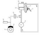
도 1은 본 발명의 실시예에 따른 차량 제동 시스템의 예시도이다.
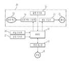
도 2는 본 발명의 실시예에 따른 차량 제동 시스템의 제어 구성도이다.
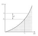
도 3은 본 발명의 실시예에 따른 차량 브레이크 시스템에서 시간에 따른 회생 제동력 및 유압 제동력 그래프이다.
도 4는 본 발명의 실시예에 따른 차량 브레이크 시스템에서 인렛 밸브의 전류에 따른 입출력단의 차압 그래프이다.
도 5는 본 발명의 실시예에 따른 차량 제동 시스템의 제어 순서도이다.1 is an exemplary view of a vehicle braking system according to an embodiment of the present invention.
2 is a control block diagram of a vehicle braking system according to an exemplary embodiment of the present invention.
3 is a graph showing regenerative braking force and hydraulic braking force with time in a vehicle brake system according to an exemplary embodiment of the present invention.
Figure 4 is a differential pressure graph of the input and output terminal according to the current of the inlet valve in the vehicle brake system according to an embodiment of the present invention.
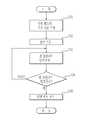
5 is a control flowchart of a vehicle braking system according to an exemplary embodiment of the present invention.
이하에서는 첨부도면을 참조하여 본 발명에 대해 상세히 설명한다.Hereinafter, the present invention will be described in detail with reference to the accompanying drawings.
도 1은 본 발명의 실시예에 따른 차량 제동 시스템의 예시도이고, 도 2는 본 발명의 실시예에 따른 차량 제동 시스템의 제어 구성도이다.1 is an exemplary view of a vehicle braking system according to an embodiment of the present invention, Figure 2 is a control block diagram of a vehicle braking system according to an embodiment of the present invention.
도 1에 도시된 바와 같이 차량 제동 시스템은, 차량의 전후좌우에 회전 가능하게 마련된 차륜(10)과, 운전자의 의지에 대응하는 제동력(즉, 목표 제동력)으로 차량을 제동시키는 브레이크 페달(21)과, 브레이크 페달(21)의 답력을 배력시키는 부스터(22)와, 부스터(22)의 배력에 의해 유압을 발생시키는 마스터 실린더(23)와, 마스터 실린더(23)에서 발생한 유압(Pm)을 각 차륜(10) 측으로 전달하는 유압라인과, 마스터 실린더(23)에 장착되어 각 차륜(10) 측 유압라인에 공급되는 브레이크액을 저장하는 리저버(24)와, 각 차륜(10)에 설치되어 유압라인을 통하여 공급되는 유압(Pw) 작용력을 기계적 힘으로 변환하는 휠 실린더(25)와, 브레이크 페달(21)의 가압상태를 검출하는 페달 감지부(26)와, 마스터 실린더(23)의 유압을 감지하는 유압 감지부(27)와, 브레이크 페달(21)의 답력에 기초하여 리저버(24)에서 휠 실린더(25)로 공급되는 유압(Pw) 작용력을 증압 또는 감압하여 압력을 조절하는 유압제동조절부(30)를 포함한다.As shown in FIG. 1, a vehicle braking system includes a
좀 더 구체적으로 도 2에 도시된 바와 같이 유압제동조절부(30)는 리저버(24)의 브레이크 액을 펌핑하여 각 휠 실린더(25) 측으로 공급하는 펌프(31)와, 제어부(50)의 명령에 대응하여 펌프(31)를 구동시키는 펌프 구동부(33)와, 각 휠 실린더(25)의 입구 측 유압라인에 마련되어 펌프(31) 구동 시 휠 실린더(25)와 리저버(24) 간의 유압라인을 개방하는 인렛 밸브(32)와, 제어부(50)의 명령에 대응하여 인렛 밸브(32)를 구동시키는 인렛 밸브 구동부(34)를포함한다. 아울러 펌프(31)에 의해 펌핑된 브레이크 액을 저장하는 어큐뮬레이터를 더 포함하는 것도 가능하다.More specifically, as shown in FIG. 2, the hydraulic
이러한 유압제동조절부(30)는 회생 제동력이 감소하면, 목표 제동력에 맞게 유압 제동력을 증가시킨다. 이 경우, 펌프(31)를 구동시키고 인렛 밸브(32)를 개방하여 리저버(24)의 브레이크 액을 휠 실린더(25)로 유입시켜 유압을 공급함으로써 유압 제동력을 증가시킨다. 이 때, 마스터 실린더(23) 측의 유압라인을 거치지 않고 리저버(25)와 펌프(31) 사이에 연결된 유압라인을 통해 리저버(25)로부터 휠 실린더(25)로 유압을 직접 형성함으로써 브레이크 페달(21)이 꺼지는 것을 방지할 수 있다.When the regenerative braking force is reduced, the hydraulic
그리고 유압제동조절부(30)는 회생 제동력이 증가하면, 목표 제동력에 도달하도록 유압 제동력을 감소시킨다. 이 경우, 펌프(31)를 정지시키고 휠 실린더(25)에서 리저버(24)로 브레이크 액이 귀환되도록 함으로써 휠 실린더(24) 내의 유압을 감소시킨다.And when the regenerative braking force is increased, the hydraulic
도 2에 도시된 바와 같이 차량 제동 시스템은, 모터(41)를 정/역회전시켜 차량의 구동력 및 회생제동력을 발생시켜 차량의 구동 및 회생 제동을 수행하는 회생제동부(40)와, 페달 감지부(26)를 통해 감지된 목표 제동력에 대응하는 회생 제동력 및 유압 제동력이 발생되도록 유압제동조절부(30) 및 회생제동부(40)를 제어하는 제어부(50)를 더 포함한다.As shown in FIG. 2, the vehicle braking system includes a
좀 더 구체적으로 회생제동부(40)는 제어부(50)의 제어신호에 의해 차량이 주행하다가 제동되면 플레밍의 법칙에 의해 역기전력을 발생하는 모터(41), 제어부(50)의 제어신호에 따라 모터(41)에 동력을 공급하는 배터리(미도시)를 포함한다.More specifically, the
이러한 회생제동부(40)는 제어부(50)의 제어신호에 대응하는 모터(41)의 회전력으로 에너지 재생 작동을 함과 동시에 회전저항을 발생시켜 회생제동을 수행한다. 여기서, 회생제동이라 함은 차량의 제동 시 직진하려는 차량의 관성력을 모터(41)로 흡수시켜 차량을 제동시키는 것으로, 이때 모터(41)는 역기전력이 발생되고 역기전력에 의해 발생된 에너지는 배터리에 저장된다.The
그리고 회생제동부(40)는 모터(41)의 역기전력을 제어부(50)로 전송한다.The
제어부(50)는 페달 감지부(26)로부터 전달된 감지신호에 기초하여 운전자의 의지에 따른 목표 제동력을 판단하고, 회생제동부(40)의 동작을 제어한 후 모터(41)의 역기전력에 대응하는 회생 제동력을 산출한다. 아울러 제어부(50)는 목표 제동력 산출 시 페달 감지부(26)와 유압 감지부(27)의 감지 신호에 기초하여 목표 제동력을 산출하는 것도 가능하다.The
도 3에 도시된 바와 같이, 운전자의 제동 의지에 따라 차량의 속도(S)가 감소한다. 이때 목표 제동력(T)과 회생 제동력(R)을 비교하여 차륜 제동에 필요한 유압 제동력(F)을 판단한다. 즉, 유압제동력(F)은 목표제동력(T)에서 회생 제동력(R)을 차감한 값이다.As shown in FIG. 3, the speed S of the vehicle decreases according to the braking will of the driver. At this time, by comparing the target braking force (T) and the regenerative braking force (R) to determine the hydraulic braking force (F) required for the wheel braking. That is, the hydraulic braking force F is a value obtained by subtracting the regenerative braking force R from the target braking force T. FIG.
제어부(50)는 유압제동조절부(30)의 펌프구동부(33) 및 인렛 밸브 구동부(34)를 제어하여 각 차륜(10)의 휠 실린더(25)에 유압 제동력이 공급되도록 함으로써 차량을 제동시킨다. 즉, 회생 제동력이 작은 경우에는 유압 제동력을 크게 하도록 유압제동조절부(30)를 제어하여 유압 제동압을 증압(A)시킴으로써 운전자가 원하는 제동력을 구현할 수 있다. 만약 모터에 의해 생성되는 회생 제동력이 큰 경우에는 유압 제동력을 작게 하도록 유압제동조절부(30)를 제어하여 유압 제동압을 감압시킨다.The
이를 좀 더 구체적으로 설명하도록 한다.This will be explained in more detail.
제어부(50)는 제동 시 인렛 밸브(32)에 인가할 기준 전류를 설정하고, 인렛 밸브 구동부(34)의 구동을 제어하여 인렛 밸브(32)로 설정된 기준 전류가 인가되도록 하며, 인렛 밸브(32)에 기준 전류 인가 시 펌프 구동부(33)를 제어하여 펌프(31)가 구동되도록 한다.The
이때 기준 전류는 인렛 밸브(32)의 입출력단의 차압을 현재 차압(Po)으로 유지시킬 수 있는 최소 전류(Io)로 설정한다.At this time, the reference current is set to a minimum current Io that can maintain the differential pressure at the input / output terminal of the
이러한 인렛 밸브(Inlet Valve, 32)는 통전되기 전에는 밸브 유로를 개방 상태로 유지하는 노멀 오픈 솔레노이드 밸브로, 인렛 밸브(32)는 제동 전 기준 전류 이상의 전류가 인가되어 폐쇄 상태를 유지하고, 이때 인렛 밸브(32)의 입출력 단에는 일정 차압이 유지된다.The
도 4는 인렛 밸브에 인가된 전류량에 따른 차압 그래프로, 도 4에 도시된 바와 같이 인렛 밸브(32)에 기준 전류(Io)가 인가되는 상태에서 인렛 밸브(32)의 입출력 단의 차압(Po)이 최대 차압(P) 이상이 되면 인렛 밸브(32)를 통해 펌프(31)에 의해 펌핑된 브레이크 액이 휠 실린더(25)로 공급된다.4 is a differential pressure graph according to the amount of current applied to the inlet valve, and as shown in FIG. 4, the differential pressure Po of the input / output stage of the
이때 인렛 밸브(32)가 펌프(31)의 압력을 이기지 못하고 펌프(31)에 의해 펌핑된 브레이크 액이 인렛 밸브(32)를 통해 휠 실린더(25)로 공급되는 시점이 펌프(31)의 펌핑에 의한 실제 압력 발생 시점이 된다.At this time, when the
이 시점은 휠 실린더(25)와 인렛 밸브(32) 사이의 유압라인에 마련된 휠압 감지부(35)의 압력 감지에 의해 감지된다. 이 때 휠압 감지부(35)는 휠 실린더(25) 측 유압라인의 압력을 감지하여 제어부(50)로 전송한다.This time point is detected by pressure sensing of the wheel
즉, 인렛 밸브(32)의 입출력 단의 차압 변동이 감지된 변동 시간은 펌프(31)의 압력 발생 지연 시간이 된다. 이에 따라 펌프(31)의 압력 발생 지연 시간은 휠압 감지부(35)를 통해 감지된 휠 실린더의 압력에 기초하여 간접적으로 측정된다.That is, the variation time in which the differential pressure variation of the input / output stage of the
이와 같이 펌프(31)의 압력 발생 지연 시간은 휠압 감지부(35)를 통해 감지된 휠 실린더의 압력에 기초하여 간접적으로 측정된다.As such, the pressure generation delay time of the
제어부(50)는 휠압 감지부(35)로부터 전송된 압력을 모니터링하여 펌프(31)의 압력 발생 지연 시간을 판단하고, 펌프(31)의 압력 발생 지연 시간이 경과되었다고 판단되면 휠압 감지부(35)로부터 전송된 압력이 상승하는지 판단하고, 이때 휠 실린더(25)의 압력(Pw)이 상승한다고 판단되면 인렛 밸브 구동부(34)를 제어하여 인렛 밸브(32)가 구동되도록 함으로써 마스터 실린더(23)의 압력(Pm)이 휠 실린더(25)로 인가되는 것을 방지하여 마스터 실린더(23)의 압력을 일정하게 유지시킬 수 있다.The
이와 같이 인렛 밸브의 전류에 따른 차압 특성을 이용하여 직접 측정할 수 없는 펌프(31)에 의한 펌핑 압력의 증가를 감지할 수 있다. 즉 펌프에 의해 발생되는 차압은 휠 실린더(25)의 압력으로 인가되기 때문에, 휠압 감지부(35)를 통해 실제 펌핑에 의한 압력이 발생하고 있음을 파악할 수 있다.As such, an increase in the pumping pressure by the
이와 같이 펌프의 펌핑 압력이 실제로 발생하는 시점부터 인렛 밸브의 제어를 수행함으로써 마스터 실린더의 압력 강하를 방지할 수 있고 운전자의 제동 이질감을 제거할 수 있다.As such, by performing the control of the inlet valve from the time when the pumping pressure of the pump is actually generated, it is possible to prevent the pressure drop of the master cylinder and to remove the driver's braking heterogeneity.
또한 마스터 실린더의 압력을 유지하면서 압력 발생 지연 현상을 고려하여 펌프 및 인렛 밸브를 순차적으로 제어함으로써 압력 제어 정밀도를 향상시킬 수 있다.In addition, the pressure control accuracy can be improved by sequentially controlling the pump and the inlet valve in consideration of the pressure generation delay phenomenon while maintaining the pressure of the master cylinder.
도 5는 본 발명의 실시예에 따른 차량의 브레이크 시스템의 제어 방법으로, 도 1 및 도 2를 참조하여 설명하도록 한다.5 is a control method of a brake system of a vehicle according to an exemplary embodiment of the present invention, which will be described with reference to FIGS. 1 and 2.
차량의 감속이나 정지를 위해 브레이크 페달(21)이 가압되면, 모터(41)를 제어하여 회생제동을 수행한다. 이때 페달 감지부(26) 및 유압 감지부(27)에서 감지된 신호를 기초로 하여 운전자가 원하는 목표 제동력을 판단하고, 산출된 목표 제동력을 각 전륜 및 후륜(10) 측의 휠 실린더(25)로 각각 배분한다.When the
다음, 모터(41)의 회전속도, 배터리(미도시)의 충전상태, 차량 상태 중 적어도 하나를 기초로 하여 회생 제동력을 산출하고, 산출된 회생제동력을 기초로 하여 목표 제동력에 맞출 수 있는 유압 제동력을 산출한다.Next, the regenerative braking force is calculated based on at least one of the rotational speed of the
도 3에 도시된 바와 같이, 운전자의 제동 의지에 따라 차량의 속도(S)가 감소한다. 이때 목표 제동력(T)과 모터(41)의 회생 제동력(R)을 비교하여 차륜 제동에 필요한 유압 제동력(F)을 판단한다. 즉, 유압제동력(F)은 목표제동력(T)에서 회생 제동력(R)을 차감한 값이다.As shown in FIG. 3, the speed S of the vehicle decreases according to the braking will of the driver. At this time, by comparing the target braking force (T) and the regenerative braking force (R) of the
다음 제동 시 인렛 밸브(32)에 인가할 기준 전류를 설정(10)하고, 인렛 밸브(32)로 설정된 기준 전류를 인가하며, 펌프(31)를 구동(102)시킨다.Next, a reference current to be applied to the
이때 기준 전류는 인렛 밸브(32)의 입출력단의 차압을 현재 차압으로 유지시킬 수 있는 최소 전류로 설정한다.At this time, the reference current is set to a minimum current that can maintain the differential pressure at the input / output terminal of the
다음 펌프(31)의 구동에 따라 유압라인에 압력이 발생하게 되고, 이로 인해 인렛 밸브(32)는 펌프(31)의 압력(Pp)을 이기지 못하게 되어 인렛 밸브(32)의 입출력 단의 차압이 변동된다.Next, pressure is generated in the hydraulic line according to the driving of the
즉, 인렛 밸브(32)의 입출력 단의 차압이 최대 차압 이상이 되면 펌프(31)에 의해 펌핑된 브레이크 액이 인렛 밸브(32)를 통해 휠 실린더(25)로 공급된다.That is, when the differential pressure at the input / output end of the
이때 인렛 밸브(32)가 펌프(31)의 압력을 이기지 못하고 펌프(31)에 의해 펌핑된 브레이크 액이 인렛 밸브(32)를 통해 휠 실린더(25)로 공급되는 시점이 펌프(31)의 펌핑에 의한 실제 압력 발생 시점이 되고, 이 시점은 휠 실린더(25)의 입구 측에 마련된 휠압 감지부(35)의 압력 감지에 의해 감지(103)된다.At this time, when the
즉, 인렛 밸브(32)의 입출력 단의 차압 변동이 감지된 변동 시간은 펌프(31)의 압력 발생 지연 시간이 된다. 이에 따라 펌프(31)의 압력 발생 지연 시간은 휠압 감지부(35)를 통해 감지된 휠 실린더의 압력에 기초하여 간접적으로 측정된다.That is, the variation time in which the differential pressure variation of the input / output stage of the
휠압 감지부(35)를 통해 감지된 압력에 기초하여 펌프(31)의 압력 발생 지연 시간이 경과되었다고 판단되면 휠압 감지부(35)를 통해 감지된 압력이 상승(104)하는지 판단하고, 이때 휠 실린더(25)의 압력(Pw)이 상승한다고 판단되면 인렛 밸브 구동부(34)를 제어(105)하여 인렛 밸브(32)가 구동되도록 함으로써 마스터 실린더(23)의 압력(Pm)이 휠 실린더(25)로 인가되는 것을 방지하여 마스터 실린더(23)의 압력을 일정하게 유지시킬 수 있다.When it is determined that the pressure generation delay time of the
이와 같이 인렛 밸브의 전류에 따른 차압 특성을 이용하여 직접 측정할 수 없는 펌프(31)에 의한 펌핑 압력의 증가를 감지할 수 있다. 즉 펌프에 의해 발생되는 차압은 휠 실린더(25)의 압력으로 인가되기 때문에, 휠압 감지부(35)를 통해 실제 펌핑에 의한 압력이 발생하고 있음을 파악할 수 있다.As such, an increase in the pumping pressure by the
이와 같이 펌프의 펌핑 압력이 실제로 발생하는 시점부터 인렛 밸브의 제어를 수행함으로써 마스터 실린더의 압력 강하를 방지할 수 있고 운전자의 제동 이질감을 제거할 수 있다.As such, by performing the control of the inlet valve from the time when the pumping pressure of the pump is actually generated, it is possible to prevent the pressure drop of the master cylinder and to remove the driver's braking heterogeneity.
또한 마스터 실린더의 압력을 유지하면서 압력 발생 지연 현상을 고려하여 펌프 및 인렛 밸브를 순차적으로 제어함으로써 압력 제어 정밀도를 향상시킬 수 있다.
In addition, the pressure control accuracy can be improved by sequentially controlling the pump and the inlet valve in consideration of the pressure generation delay phenomenon while maintaining the pressure of the master cylinder.
10: 차륜 21: 브레이크 페달
22: 부스터 23: 마스터 실린더
24: 리저버 25: 휠 실린더
26: 페달 감지부 27: 유압 감지부
30: 유압제동조절부 31: 펌프
32: 인렛 밸브 33: 펌프 구동부
34: 인렛 밸브 구동부 35: 휠압 감지부
40: 회생 제동부 41: 모터
50: 제어부
10: wheel 21: brake pedal
22: booster 23: master cylinder
24: reservoir 25: wheel cylinder
26: pedal detection unit 27: hydraulic pressure detection unit
30: hydraulic brake control unit 31: pump
32: inlet valve 33: pump drive portion
34: inlet valve drive unit 35: wheel pressure detection unit
40: regenerative braking part 41: motor
50: control unit
Claims (9)
Translated fromKorean상기 휠 실린더로 공급되는 유압을 조절하는 인렛 밸브와 펌프를 가지는 유압 제동 조절부;
상기 휠 실린더와 인렛 밸브 사이의 유압 라인에 마련되어 압력을 감지하는 휠압 감지부;
상기 차량의 제동 시 상기 인렛 밸브의 차압을 유지시키는 기준 전류를 설정하고, 상기 인렛 밸브에 기준 전류의 인가를 제어하면서 상기 펌프를 구동시키고, 상기 휠압 감지부를 통해 감지된 압력에 기초하여 상기 인렛 밸브를 제어하여 상기 휠 실린더를 증압시키는 제어부를 포함하는 차량 제동 시스템.A wheel cylinder generating hydraulic braking force when braking the vehicle;
A hydraulic braking control unit having an inlet valve and a pump for adjusting the hydraulic pressure supplied to the wheel cylinder;
A wheel pressure sensing unit provided in a hydraulic line between the wheel cylinder and the inlet valve to sense a pressure;
Set a reference current for maintaining the differential pressure of the inlet valve when braking the vehicle, driving the pump while controlling the application of a reference current to the inlet valve, the inlet valve based on the pressure sensed through the wheel pressure sensing unit And a controller configured to control the controller to boost the wheel cylinder.
상기 휠압 감지부를 통해 감지된 압력이 상승하면 상기 펌프의 압력 발생 지연 시간이 경과되었다고 판단하고, 상기 인렛 밸브를 제어하는 차량 제동 시스템.The method of claim 1, wherein the control unit,
And determining that the pressure generation delay time of the pump has elapsed when the pressure detected by the wheel pressure sensing unit rises, and controls the inlet valve.
상기 휠압 감지부를 통해 감지된 압력이 상승하면 상기 휠 실린더로 공급되는 마스터 실린더의 압력이 차단되도록 상기 인렛 밸브를 제어하는 차량 제동 시스템.The method of claim 1, wherein the control unit,
And controlling the inlet valve to block the pressure of the master cylinder supplied to the wheel cylinder when the pressure sensed through the wheel pressure sensor increases.
상기 인렛 밸브의 입출력 단의 현재 차압을 유지시키는 최소 전류를 기준 전류로 설정하는 차량 제동 시스템.The method of claim 1, wherein the control unit,
And a minimum current for maintaining a current differential pressure at the input / output stage of the inlet valve as a reference current.
차량의 제동을 지시하는 브레이크 페달;
상기 브레이크 페달의 가압에 대응하여 상기 차량의 회생 제동력을 발생시키는 회생 제동부를 더 포함하고,
상기 제어부는, 상기 페달 가압에 대응하는 목표 제동력을 산출하고, 상기 목표 제동력과 회생 제동력을 비교하여 유압 제동력을 산출하고, 산출된 유압 제동력에 대응하여 상기 인렛 밸브와 펌프를 순차적으로 제어하여 상기 휠 실린더를 증압시키는 차량 제동 시스템.The method of claim 1,
A brake pedal for instructing braking of the vehicle;
Further comprising a regenerative braking unit for generating a regenerative braking force of the vehicle in response to the pressing of the brake pedal,
The controller calculates a target braking force corresponding to the pedal pressurization, compares the target braking force with a regenerative braking force, calculates a hydraulic braking force, and sequentially controls the inlet valve and the pump in response to the calculated hydraulic braking force. Vehicle braking system to boost the cylinder.
상기 인렛 밸브에 상기 기준 전류를 인가한 상태에서 펌프를 구동시키고,
상기 펌프 구동에 따른 상기 휠 실린더의 압력을 감지하고,
상기 감지된 휠 실린더의 압력이 변화되면 상기 인렛 밸브를 제어하여 휠 실린더를 증압시키는 차량 제동 시스템의 제어 방법.When the brake pedal of the vehicle is pressed by the driver, the reference current of the inlet valve is set,
The pump is driven while the reference current is applied to the inlet valve,
Detect the pressure of the wheel cylinder according to the pump drive,
And controlling the inlet valve to boost the wheel cylinder when the sensed pressure of the wheel cylinder changes.
상기 인렛 밸브의 입출력 단의 현재 차압을 감지하고,
상기 현재 차압을 유지시키는 최소 전류를 기준 전류로 설정하는 차량 제동 시스템의 제어 방법.The method of claim 6, wherein the setting of the reference current,
Detecting the current differential pressure at the input / output end of the inlet valve,
And controlling the minimum current to maintain the current differential pressure as a reference current.
상기 휠 실린더의 압력이 변화된다고 판단되면 상기 압력이 변화된 시점부터 상기 펌프의 실질적 구동으로 판단하는 것을 더 포함하는 차량 제동 시스템의 제어 방법.The method of claim 6, wherein determining whether the pressure of the wheel cylinder is changed,
If it is determined that the pressure of the wheel cylinder is to change the control method of the vehicle braking system further comprises determining that the actual drive of the pump from the time point when the pressure is changed.
상기 차량의 브레이크 페달의 가압에 대응하는 목표 제동력 및 회생 제동력을 산출하고,
상기 목표 제동력과 회생 제동력을 비교하여 유압 제동력을 산출하고,
상기 산출된 유압 제동력에 기초하여 상기 펌프가 실질적으로 구동하는 시점에 상기 인렛 밸브를 제어하여 상기 휠 실린더를 증압시키는 것을 더 포함하는 차량 제동 시스템의 제어 방법.The method of claim 8,
Calculating a target braking force and a regenerative braking force corresponding to the pressurization of the brake pedal of the vehicle,
Hydraulic braking force is calculated by comparing the target braking force with the regenerative braking force,
And controlling the inlet valve to boost the wheel cylinder at a time when the pump is substantially driven based on the calculated hydraulic braking force.
Priority Applications (1)
| Application Number | Priority Date | Filing Date | Title |
|---|---|---|---|
| KR1020100028217AKR101402707B1 (en) | 2010-03-30 | 2010-03-30 | Vehicles braking system and method of controlling the same |
Applications Claiming Priority (1)
| Application Number | Priority Date | Filing Date | Title |
|---|---|---|---|
| KR1020100028217AKR101402707B1 (en) | 2010-03-30 | 2010-03-30 | Vehicles braking system and method of controlling the same |
Publications (2)
| Publication Number | Publication Date |
|---|---|
| KR20110108813Atrue KR20110108813A (en) | 2011-10-06 |
| KR101402707B1 KR101402707B1 (en) | 2014-06-03 |
Family
ID=45026245
Family Applications (1)
| Application Number | Title | Priority Date | Filing Date |
|---|---|---|---|
| KR1020100028217AActiveKR101402707B1 (en) | 2010-03-30 | 2010-03-30 | Vehicles braking system and method of controlling the same |
Country Status (1)
| Country | Link |
|---|---|
| KR (1) | KR101402707B1 (en) |
Cited By (3)
| Publication number | Priority date | Publication date | Assignee | Title |
|---|---|---|---|---|
| KR20150117898A (en)* | 2014-04-11 | 2015-10-21 | 주식회사 만도 | Apparatus for controlling oil pressure in vehicle and method for controlling oil pressure thereof |
| KR20160039823A (en)* | 2014-10-02 | 2016-04-12 | 현대모비스 주식회사 | Regeneratve braking system |
| KR20200006869A (en)* | 2018-07-11 | 2020-01-21 | 현대모비스 주식회사 | Apparatus for braking of vehicle |
Families Citing this family (1)
| Publication number | Priority date | Publication date | Assignee | Title |
|---|---|---|---|---|
| KR101704176B1 (en) | 2015-03-23 | 2017-02-07 | 현대자동차주식회사 | Brake control method for hybrid electric vehicle |
Family Cites Families (3)
| Publication number | Priority date | Publication date | Assignee | Title |
|---|---|---|---|---|
| JPH09193766A (en)* | 1996-01-23 | 1997-07-29 | Akebono Brake Ind Co Ltd | Brake control device |
| JP4379272B2 (en)* | 2004-09-14 | 2009-12-09 | 株式会社アドヴィックス | Brake control device for vehicle |
| KR101269927B1 (en)* | 2008-09-18 | 2013-05-31 | 주식회사 만도 | Controlling method of oil pressure brake during regenerative brake for vehicle equipped with the electric motor |
- 2010
- 2010-03-30KRKR1020100028217Apatent/KR101402707B1/enactiveActive
Cited By (3)
| Publication number | Priority date | Publication date | Assignee | Title |
|---|---|---|---|---|
| KR20150117898A (en)* | 2014-04-11 | 2015-10-21 | 주식회사 만도 | Apparatus for controlling oil pressure in vehicle and method for controlling oil pressure thereof |
| KR20160039823A (en)* | 2014-10-02 | 2016-04-12 | 현대모비스 주식회사 | Regeneratve braking system |
| KR20200006869A (en)* | 2018-07-11 | 2020-01-21 | 현대모비스 주식회사 | Apparatus for braking of vehicle |
Also Published As
| Publication number | Publication date |
|---|---|
| KR101402707B1 (en) | 2014-06-03 |
Similar Documents
| Publication | Publication Date | Title |
|---|---|---|
| KR101259361B1 (en) | Vehicles braking system and method of controlling the same | |
| KR100819978B1 (en) | Brake system and control method of hybrid and electric vehicle | |
| US8960811B2 (en) | Brake apparatus for vehicle | |
| US8801110B2 (en) | Vehicle brake device | |
| US20110266106A1 (en) | Brake control apparatus and brake control method | |
| US8777336B2 (en) | Brake apparatus for vehicle | |
| US20120193975A1 (en) | Vehicle brake apparatus | |
| KR101301906B1 (en) | Hydraulic brake device and method for controlling the same | |
| US10189454B2 (en) | Brake system | |
| US20140008966A1 (en) | Brake device for vehicle | |
| US9376097B2 (en) | Vehicle brake device and method of controlling the same | |
| KR101402707B1 (en) | Vehicles braking system and method of controlling the same | |
| KR101350844B1 (en) | Offset compensation apparatus of brake pedal stroke sensor and method thereof | |
| JP2007276655A (en) | Vehicular brake control device | |
| KR101252248B1 (en) | Offset compensation apparatus of pedal stroke sensor and method thereof | |
| JP2012131299A (en) | Brake device for vehicle | |
| KR20120139896A (en) | Vehicles active hydraulic boost apparatus and method of controlling the same | |
| KR20120048088A (en) | Vehicles hydraulic control apparatus and method of controlling the same | |
| KR101402717B1 (en) | Vehicles braking system and method of controlling the same | |
| KR101380866B1 (en) | Vehicle brake system and control method thereof | |
| KR101316584B1 (en) | Vehicles braking system and method of controlling the same | |
| KR102231112B1 (en) | Active hydraulic booster system in vehice and control method thereof | |
| KR101238282B1 (en) | Active hydraulic booster and failure detection method of pedal travel sensor in active hydraulic booster | |
| KR101901445B1 (en) | Vehicles hydraulic control apparatus and method of controlling the same | |
| KR102270208B1 (en) | Vehicle hydraulic brake device and control method thereof |
Legal Events
| Date | Code | Title | Description |
|---|---|---|---|
| PA0109 | Patent application | Patent event code:PA01091R01D Comment text:Patent Application Patent event date:20100330 | |
| PG1501 | Laying open of application | ||
| A201 | Request for examination | ||
| PA0201 | Request for examination | Patent event code:PA02012R01D Patent event date:20121205 Comment text:Request for Examination of Application Patent event code:PA02011R01I Patent event date:20100330 Comment text:Patent Application | |
| E902 | Notification of reason for refusal | ||
| PE0902 | Notice of grounds for rejection | Comment text:Notification of reason for refusal Patent event date:20131121 Patent event code:PE09021S01D | |
| E701 | Decision to grant or registration of patent right | ||
| PE0701 | Decision of registration | Patent event code:PE07011S01D Comment text:Decision to Grant Registration Patent event date:20140521 | |
| GRNT | Written decision to grant | ||
| PR0701 | Registration of establishment | Comment text:Registration of Establishment Patent event date:20140527 Patent event code:PR07011E01D | |
| PR1002 | Payment of registration fee | Payment date:20140528 End annual number:3 Start annual number:1 | |
| PG1601 | Publication of registration | ||
| FPAY | Annual fee payment | Payment date:20170320 Year of fee payment:4 | |
| PR1001 | Payment of annual fee | Payment date:20170320 Start annual number:4 End annual number:4 | |
| FPAY | Annual fee payment | Payment date:20190403 Year of fee payment:6 | |
| PR1001 | Payment of annual fee | Payment date:20190403 Start annual number:6 End annual number:6 | |
| PR1001 | Payment of annual fee | Payment date:20200428 Start annual number:7 End annual number:7 | |
| PR1001 | Payment of annual fee | Payment date:20210324 Start annual number:8 End annual number:8 | |
| PR1001 | Payment of annual fee | Payment date:20220321 Start annual number:9 End annual number:9 | |
| PR1001 | Payment of annual fee | Payment date:20230322 Start annual number:10 End annual number:10 |