KR20110098674A - Fishing shoes - Google Patents
Fishing shoesDownload PDFInfo
- Publication number
- KR20110098674A KR20110098674AKR1020110017092AKR20110017092AKR20110098674AKR 20110098674 AKR20110098674 AKR 20110098674AKR 1020110017092 AKR1020110017092 AKR 1020110017092AKR 20110017092 AKR20110017092 AKR 20110017092AKR 20110098674 AKR20110098674 AKR 20110098674A
- Authority
- KR
- South Korea
- Prior art keywords
- sole
- pin
- fishing
- plate
- shoe
- Prior art date
- Legal status (The legal status is an assumption and is not a legal conclusion. Google has not performed a legal analysis and makes no representation as to the accuracy of the status listed.)
- Granted
Links
Images


Classifications
- A—HUMAN NECESSITIES
- A43—FOOTWEAR
- A43B—CHARACTERISTIC FEATURES OF FOOTWEAR; PARTS OF FOOTWEAR
- A43B13/00—Soles; Sole-and-heel integral units
- A43B13/14—Soles; Sole-and-heel integral units characterised by the constructive form
- A43B13/22—Soles made slip-preventing or wear-resisting, e.g. by impregnation or spreading a wear-resisting layer
- A—HUMAN NECESSITIES
- A01—AGRICULTURE; FORESTRY; ANIMAL HUSBANDRY; HUNTING; TRAPPING; FISHING
- A01K—ANIMAL HUSBANDRY; AVICULTURE; APICULTURE; PISCICULTURE; FISHING; REARING OR BREEDING ANIMALS, NOT OTHERWISE PROVIDED FOR; NEW BREEDS OF ANIMALS
- A01K97/00—Accessories for angling
- A—HUMAN NECESSITIES
- A43—FOOTWEAR
- A43B—CHARACTERISTIC FEATURES OF FOOTWEAR; PARTS OF FOOTWEAR
- A43B13/00—Soles; Sole-and-heel integral units
- A43B13/14—Soles; Sole-and-heel integral units characterised by the constructive form
- A43B13/22—Soles made slip-preventing or wear-resisting, e.g. by impregnation or spreading a wear-resisting layer
- A43B13/24—Soles made slip-preventing or wear-resisting, e.g. by impregnation or spreading a wear-resisting layer by use of insertions
- A43B13/26—Soles made slip-preventing or wear-resisting, e.g. by impregnation or spreading a wear-resisting layer by use of insertions projecting beyond the sole surface
- A—HUMAN NECESSITIES
- A43—FOOTWEAR
- A43B—CHARACTERISTIC FEATURES OF FOOTWEAR; PARTS OF FOOTWEAR
- A43B5/00—Footwear for sporting purposes
- A43B5/002—Mountain boots or shoes
Landscapes
- Life Sciences & Earth Sciences (AREA)
- Environmental Sciences (AREA)
- Health & Medical Sciences (AREA)
- General Health & Medical Sciences (AREA)
- Physical Education & Sports Medicine (AREA)
- Animal Husbandry (AREA)
- Biodiversity & Conservation Biology (AREA)
- Footwear And Its Accessory, Manufacturing Method And Apparatuses (AREA)
Abstract
Translated fromKoreanDescription
Translated fromKorean본 발명은 주로 낚시를 할 때에 사용되는 낚시용 신발에 관한 것으로, 상세하게는 신발창의 이면에 미끄러짐 방지 부재를 고정한 낚시용 신발에 관한 것이다.BACKGROUND OF THE INVENTION 1. Field of the Invention The present invention relates to fishing shoes mainly used for fishing, and more particularly, to fishing shoes in which a slip preventing member is fixed to a rear surface of a sole.
종래, 계류 낚시나 갯바위 낚시 등에 사용되는 낚시용 신발은, 미끄러지기 어려운 신발창 구조를 구비하고 있고, 예를 들어 특허 문헌 1에 보여지는 바와 같이, 신발 본체의 신발창[아우터 솔(outer sole)]에, 돌기나 핀 또는 스파이크 핀을 고정한 것이 알려져 있다. 이러한 돌기나 핀 또는 스파이크 핀을 신발창에 고정함으로써, 바위가 많은 곳 등의 미끄러지기 쉬운 부분을 걸어도 미끄러지기 어려워져, 낚시하는 사람은 안심하고 낚시를 행하는 것이 가능해진다.Background Art Conventionally, fishing shoes used for mooring fishing or rock fishing have a non-slip sole structure, and as shown in, for example, Patent Document 1, a shoe sole (outer sole) of a shoe body. It is known to fix projections, pins or spike pins. By fixing such protrusions, pins, or spike pins on the sole, it becomes difficult to slip even when walking on a slippery part such as a rocky place or the like, and a fisher can fish with confidence.
상기한 종래의 낚시용 신발은, 핀이 지면이나 바위가 많은 곳과 같은 요철에 파고 들어감으로써 미끄러짐을 방지하고 있지만, 보행시에 신발이 접지한 후의 가로로 미끄러짐이나 세로로 미끄러짐에 대해서는 충분한 미끄러짐 방지 기능을 발휘하지 않는 경우가 있다. 즉, 신발이 접지한 후, 낚시하는 사람의 체중 이동 등에 의해 발바닥이 주연 방향으로 이동하려고 하는 경우도 있지만, 핀이나 돌기만으로는, 상기한 바와 같은 이동에 수반되는 신발창의 주연을 눌러 찌부러뜨리는 방향의 힘이 작용하였을 때, 그 힘을 충분히 받아낼 수 없어, 결과적으로 미끄러짐이 발생해 버린다. 특히, 바위가 많은 곳과 같은 요철 부분에서는, 접지시에 핀에 의해 그립이 이루어져 있어도 체중 이동되기 쉬우므로, 상기한 바와 같은 주연을 눌러 찌부러뜨리는 방향의 힘이 작용하기 쉬워, 결과적으로 미끄러짐이 발생해 버린다.The conventional fishing shoes described above prevent slipping by digging into unevenness, such as where the pins are located on the ground or rocks, but prevent slipping sufficiently against horizontal slipping and vertical slipping after the shoes are grounded during walking. It may not function. That is, after the shoes are grounded, the sole may try to move in the circumferential direction by moving the weight of the fisher, etc., but only the pins or the protrusions push the circumference of the sole along with the movement as described above. When the force acts, the force cannot be sufficiently received, resulting in slippage. In particular, in the uneven portion such as a rocky place, even if the grip is made by the pin at the time of grounding, it is easy to move the weight, so that the force in the pressing direction is easily acted as described above, resulting in slipping. Do it.
본 발명은 상기한 문제에 착안하여 이루어진 것으로, 바위가 많은 곳과 같은 요철이 있는 낚시터라도, 미끄러지기 어려운 낚시용 신발을 제공하는 것을 목적으로 한다.The present invention has been made in view of the above-described problems, and an object of the present invention is to provide a fishing shoe that is hard to slip even in a fishing field with irregularities such as a rocky place.
또한, 상기한 종래의 낚시용 신발은, 스파이크 핀을 지면이나 바위가 많은 곳과 같은 요철에 파고 들어가게 함으로써 미끄러짐을 방지하려고 하고 있지만, 신발창의 접지 상태가 전체적으로 불안정하면, 결국 보행시 등에 있어서 미끄러짐이 발생해 버린다. 특히, 해안가 등의 기복이 심한 장소에서는, 신발창의 접지 상태가 불안정해지는 경향이 있고, 그러한 장소를 안정적으로 보행하기 위해서는, 신발창이 유연하게 변형되어 기복의 변화에 잘 추종할 수 있는 것이 필요하지만, 신발창이 경질인 소재에 의해 형성되어 있으면, 그러한 변형·추종을 할 수 없어, 결과적으로 신발창의 접지 상태가 불안정해져 미끄러지기 쉬워진다. 한편, 변형·추종성을 요구하는 나머지, 신발창의 소재를 지나치게 부드럽게 하면, 그때는 미끄러짐 방지용 돌기나 스파이크 핀의 고정 지지력이 저하되어, 보행시에 연질인 신발창의 변형에 수반하여 돌기나 스파이크 핀이 흔들려, 미끄러짐 방지로서의 기능이 잘 작용하지 않게 될 우려가 있다.In addition, the conventional fishing shoes described above attempt to prevent slipping by digging spike pins into unevenness such as the ground or rocks, but if the grounding state of the sole is unstable as a whole, eventually slipping occurs during walking or the like. It happens. In particular, in places with high ups and downs, such as the shore, the grounding state of the soles tends to become unstable, and in order to walk stably, it is necessary that the soles are flexibly deformed and able to keep up with changes in ups and downs, If the sole is formed of a hard material, such deformation and tracking cannot be performed, and as a result, the grounding state of the sole is unstable and it is easy to slip. On the other hand, if the material of the sole is excessively soft while remaining demanding deformation and followability, then the fixing support force of the anti-slip protrusion and the spike pin is reduced, and the protrusion and the spike pin are shaken with the deformation of the soft sole at the time of walking. There is a fear that the function as slip prevention may not work well.
본 발명은 상기 사정에 착안하여 이루어진 것으로, 그 목적으로 하는 것은, 미끄러짐 방지용 스파이크를 흔들리게 하는 일 없이 안정적으로 보유 지지할 수 있는 한편, 지면의 기복 변화에 추종하여 안정된 접지 상태를 확보할 수 있는 신발창을 구비하는 낚시용 신발을 제공하는 데 있다.SUMMARY OF THE INVENTION The present invention has been made in view of the above circumstances, and its object is to stably hold the anti-skid spikes without shaking, and to ensure a stable ground state in accordance with the change of the ground ups and downs. To provide a fishing shoe having a sole.
상기한 목적을 달성하기 위해, 본 발명에 관한 낚시용 신발은, 신발 본체의 저면에 신발창을 고정한 구성에 있어서, 상기 신발창은, 복수의 핀 형상 돌기와, 각각의 핀 형상 돌기와 신발창 주연 사이에 배치되는 복수의 판 형상 돌기를 갖는 것을 특징으로 한다.In order to achieve the above object, in the fishing shoe according to the present invention, in the configuration in which the sole is fixed to the bottom of the shoe body, the sole is disposed between the plurality of pin-like protrusions, each of the pin-shaped protrusions and the sole circumference It is characterized by having a plurality of plate-shaped protrusions.
상기한 구성의 낚시용 신발에 따르면, 신발창에 설치된 복수의 핀 형상 돌기가, 보행할 때에 지면이나 바위가 많은 곳 등을 그립하여 미끄러짐이 방지된다. 그리고 복수의 핀 형상 돌기의 외측(핀 형상 돌기와 신발창 주연 사이)에는, 판 형상 돌기가 배치되어 있으므로, 발을 내딛기 나쁜(미끄러지기 쉬운) 장소를 보행하였을 때에 발바닥이 신발창 주연 방향으로 미끄러져도, 그 미끄러짐은, 핀 형상 돌기의 외측에 있는 판 형상 돌기의 표면(선 형상의 접지부)에 의해 받아낼 수 있으므로, 보다 효과적으로 미끄러짐을 억제하는 것이 가능해진다. 특히, 낚시하는 사람이 바위가 많은 곳과 같은 경사진 요철 부분을 보행해도, 신발창 주연 방향으로의 미끄러짐이 억제되므로, 안심하고 낚시를 하거나, 낚시터를 이동하는 것이 가능해진다.According to the fishing shoes of the above-described configuration, the plurality of pin-shaped projections provided in the sole, grip the place where there are a lot of ground, rocks or the like when walking to prevent slipping. And since the plate-like protrusions are arranged outside of the plurality of pin-shaped protrusions (between the pin-shaped protrusions and the sole periphery), even when the soles slide in the circumferential direction of the sole when walking in a place where the foot is bad (slidable), Since slipping can be picked up by the surface (linear grounding part) of the plate-shaped protrusion outside of the pin-shaped protrusion, it becomes possible to suppress slipping more effectively. In particular, even if the fisher walks on the inclined concave-convex portion such as where there are many rocks, the slip in the circumferential direction of the sole is suppressed, so that it is possible to safely fish or move the fishing ground.
또한, 상기 과제를 해결하기 위해, 본 발명은 신발 본체의 저면에 신발창을 고정한 낚시용 신발에 있어서, 상기 신발창은, 그것이 접촉하는 면의 기복 변화에 추종할 수 있는 유연성을 갖는 베이스층과, 상기 베이스층 상에 적층되어 미끄러짐 방지용 스파이크를 보유 지지하는 보유 지지층을 구비하고, 상기 보유 지지층이 상기 베이스층보다도 경질인 것을 특징으로 한다.In addition, in order to solve the above problems, the present invention provides a fishing shoe in which the sole is fixed to the bottom surface of the shoe body, the sole is a base layer having a flexibility that can follow the change of ups and downs of the contact surface, and And a holding layer which is laminated on the base layer to hold the anti-slip spikes, wherein the holding layer is harder than the base layer.
상기 구성의 낚시용 신발은, 경도가 다른 2개의 층을 적층하여 이루어지는 2층 구조의 신발창을 구비하고, 한쪽의 연질인 베이스층은, 그것이 접촉하는 면의 기복 변화에 추종할 수 있는 유연성을 갖고, 다른 쪽의 경질인 보유 지지층은, 미끄러짐 방지용 스파이크를 보유 지지한다. 따라서, 신발창은 베이스층의 유연성에 의해, 지면이나 바위가 많은 곳 등의 접촉면의 기복의 변화에 추종하여 안정된 접지 상태를 확보할 수 있는 한편, 보유 지지층의 높은 경도에 의해, 미끄러짐 방지용 스파이크를 흔들리게 하는 일 없이 안정적으로 보유 지지할 수 있어, 미끄러짐 방지로서의 스파이크의 기능을 잘 작용시킬 수 있다. 즉, 상기 구성에서는, 바위가 많은 곳 등의 기복이 심한 표면에 신발창 면의 형상을 따르게 함으로써, 점이 아닌 면에 의해, 혹은 좁은 면적이 아닌 넓은 면적에 의해 바위 표면을 받아낼 수 있고, 또한 미끄러짐 방지용 스파이크가 경질인 보유 지지층에 의해 보유 지지되므로, 스파이크의 돌출 방향에 대해 수직한 방향으로 힘이 가해져도, 스파이크가 기울어지는 것을 방지할 수 있어, 미끄러짐 방지로서의 스파이크의 기능을 확보할 수 있다. 따라서, 안정된 접지 상태를 확보하면서 스파이크의 흔들림을 방지할 수 있는, 미끄러지기 어려운 낚시용 신발을 제공할 수 있다.The fishing shoe of the above configuration has a two-layered shoe sole formed by laminating two layers of different hardness, and one of the soft base layers has the flexibility to follow the undulation change of the surface in contact with it. The other hard holding layer holds the anti-slip spike. Therefore, the sole can keep a stable ground state by following the change of the ups and downs of the contact surface such as the ground or the rocky place due to the flexibility of the base layer, while shaking the anti-slip spike by the high hardness of the holding layer. It can hold | maintain stably without rolling, and can operate the function of the spike as a slip prevention well. That is, in the above configuration, the surface of the sole is made to conform to the shape of the sole surface on a heavily undulated surface such as a large rock, so that the surface of the rock can be picked up by a surface other than a point or by a large area rather than a small area, and also slips. Since the prevention spike is held by the hard holding layer, even if a force is applied in a direction perpendicular to the direction in which the spike is projected, the spike can be prevented from inclining, thereby ensuring the function of the spike as a slip prevention. Therefore, it is possible to provide a slippery fishing shoe that can prevent the shaking of the spike while ensuring a stable ground state.
본 발명에 따르면, 바위가 많은 곳과 같은 요철이 있는 낚시터라도, 미끄러지기 어려운 낚시용 신발을 얻을 수 있다.According to the present invention, even a fishing place with irregularities such as a rocky place, a fishing shoe that is hard to slip can be obtained.
또한, 본 발명에 따르면, 미끄러짐 방지용 스파이크를 흔들리게 하는 일 없이 안정적으로 보유 지지할 수 있는 한편, 지면의 기복 변화에 추종하여 안정된 접지 상태를 확보할 수 있는 신발창을 구비하는 낚시용 신발을 제공할 수 있다.In addition, according to the present invention, while providing a fishing shoe that can be stably held without shaking the anti-slip spike, and has a sole that can ensure a stable ground state in accordance with the change of the ground ups and downs Can be.
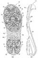
도 1은 본 발명에 관한 낚시용 신발의 일 실시 형태를 도시하는 측면도.
도 2는 도 1에 도시하는 낚시용 신발의 신발창을 도시하는 도면으로, 도 2의 (a)는 이면도, 도 2의 (b)는 측면도.
도 3은 신발창의 핀 형상 돌기와 판 형상 돌기의 부분을 확대하여 도시하는 도면.
도 4는 신발창을 도시하는 도면으로, 핀 형상 돌기와 판 형상 돌기의 작용을 설명하는 개략도.
도 5는 판 형상 돌기의 구성을 도시하는 도면으로, 도 5의 (a)는 정면도, 도 5의 (b)는 요철부에 접지한 상태를 도시하는 도면.
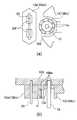
도 6의 (a)는 핀 형상 돌기와 판 형상 돌기 부분을 확대하여 도시하는 도면, 도 6의 (b)는 양 돌기 부분의 단면도.
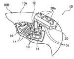
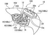
도 7은 낚시용 신발의 다른 실시 형태의 신발창을 도시하는 도면으로, 도 7의 (a)는 이면도, 도 7의 (b)는 측면도.
도 8은 신발창의 핀 형상 돌기와 판 형상 돌기의 부분을 확대하여 도시하는 도면.
도 9의 (a)는 핀 형상 돌기와 판 형상 돌기 부분을 확대하여 도시하는 도면, 도 9의 (b)는 양 돌기 부분의 단면도.1 is a side view showing one embodiment of a fishing shoe according to the present invention.
2 is a view showing the sole of the fishing shoe shown in Figure 1, Figure 2 (a) is a rear view, Figure 2 (b) is a side view.
3 is an enlarged view of a portion of a pin-like protrusion and a plate-shaped protrusion of a shoe sole;
Fig. 4 is a diagram showing a shoe sole, and is a schematic diagram illustrating the action of a pin-like protrusion and a plate-like protrusion.
FIG. 5 is a diagram showing a configuration of a plate-like protrusion, in which FIG. 5A is a front view, and FIG. 5B is a diagram showing a state in which the uneven portion is grounded.
Fig. 6A is an enlarged view of the pin-like protrusion and the plate-like protrusion, and Fig. 6B is a sectional view of both of the protrusions.
FIG. 7 is a view showing a sole of another embodiment of a fishing shoe, FIG. 7A is a rear view, and FIG. 7B is a side view.
8 is an enlarged view of a portion of a pin-like protrusion and a plate-shaped protrusion of a shoe sole;
FIG. 9A is an enlarged view of the pin-like protrusions and the plate-like protrusions, and FIG. 9B is a sectional view of both of the protrusions.
이하, 본 발명에 관한 낚시용 신발의 실시 형태 및 다른 실시 형태에 대해 도 1 내지 도 9를 참조하여 구체적으로 설명한다.EMBODIMENT OF THE INVENTION Hereinafter, embodiment and another embodiment of the fishing shoe which concerns on this invention are concretely demonstrated with reference to FIGS.
본 실시 형태의 낚시용 신발(1)은, 장화 타입(부츠 타입)에 적용되어 있고, 낚시하는 사람의 발 부분을 덮는 신발 본체(2)와, 신발 본체(2)에 대해 접착, 고정되는 신발창(솔부)(10)을 구비하여 구성된다. 이 경우, 신발 본체(2)와 신발창(10)의 고착 방법이나 구체적인 구조에 대해서는 특별히 한정되는 것은 아니며, 신발 본체(2)의 내부에 안창(이너 솔)이나 쿠션재 등이 개재되어 있어도 좋다.The shoe for fishing 1 of this embodiment is applied to the boots type (boot type), and the sole which adheres and fixes to the shoe
신발 본체(2)는, 예를 들어 고무 등의 소재로 일체 형성되어 있고, 그 이면(저면)(2a)에, 대략 동일한 형상으로 형성되고, 소정의 두께를 갖는 상기 신발창(10)이 접착 등에 의해 고정되어 있다. 또한, 신발창(10)은, 예를 들어 고무, 우레탄, EVA 등의 합성 수지에 의해 일체 형성되어 있다.The shoe
신발창(10)의 저면(10a)에는, 도 2의 (a) 또는 도 7의 (a)에 도시하는 바와 같이, 하방을 향해 돌출되는 스파이크로서의 복수의 핀 형상 돌기(12)와, 판 형상으로 형성된 스파이크로서의 판 형상 돌기(20)가 설치되어 있다. 이 경우, 핀 형상 돌기(12)는, 신발창(10)의 저면의 내측(중앙측)에 소정의 간격을 두고 설치되어 있고, 판 형상 돌기(20)는 신발창(10)의 저면의 주연측에 설치되어 있다.On the
구체적으로, 본 실시 형태의 핀 형상 돌기(12)는, 발가락끝측 영역에 있어서 발바닥면 형상을 따르도록, 폭 방향 양 사이드의 각각에 길이 방향을 따라 소정 간격을 두고 3개소씩, 발가락끝 부분에 1개소 및 중앙에 2개소의 합계 9개소 설치되어 있다. 또한, 발뒤꿈치측 영역에 있어서 폭 방향 양 사이드의 각각에, 길이 방향을 따라 소정 간격을 두고 2개소씩, 합계 4개소 설치되어 있다.Specifically, the pin-
핀 형상 돌기(12) 및 판 형상 돌기(20)는, 스테인리스 등의 금속, 강도가 높은 플라스틱 등에 의해 형성하는 것이 가능하고, 신발창(10)을 형성할 때에, 그 구성 재료에 매설되어 신발창(10)과 일체화된다. 이 경우, 핀 형상 돌기(12)는, 도 3에 도시하는 바와 같이 확대하였을 때, 그 선단이 평탄하게 되는 원기둥 형상이라도 좋고, 선단이 뾰족한 형상으로 형성되어 있어도 좋다. 또한, 판 형상 돌기(20)에 관해서는, 0.5 내지 5㎜ 정도의 두께를 갖고, 그 두께에 따라 선 형상으로 되는 접지 표면(20a)이 형성되어 있으면 좋다.The pin-shaped
핀 형상 돌기(12)는, 신발창(10)의 저면(10a)에 돌출 설치되는 것만으로도 좋지만, 미끄러짐 방지 효과를 높이도록, 도 3 또는 도 8에 도시하는 바와 같이, 신발창(10)의 표면에 링 형상의 돌기(13)를 형성해 두고, 그 중앙 위치에 돌출 설치되도록 형성해 두어도 좋다. 이 경우, 핀 형상 돌기(12)를 둘러싸는 링 형상의 돌기(13)는 다소의 두께가 있고, 그 표면에 미끄러짐 방지 효과를 높이도록 소정 간격을 두고 홈(13a)을 형성해 두는 것이 바람직하다.The pin-shaped
이러한 핀 형상 돌기(12)의 배치 형태에 따르면, 보행하였을 때에 지면 등에 파고 들어가기 쉬워지고, 또한 그 주변 영역에 있어서, 링 형상의 돌기(13)에 의한 표면이나 홈(13a)에 의해 요철 영역이 발생하므로, 전체적으로 미끄러짐 방지 효과를 높이는 것이 가능해진다.According to the arrangement of the pin-shaped
또한, 핀 형상 돌기의 주위에는, 링 형상의 돌기(13)에 더하여, 각종 요철부를 형성해도 좋다. 본 실시 형태에서는, 대략 삼각 형상의 돌기(14) 및 대략 직사각 형상의 돌기(15)를 인접하게 배치하고 있어, 미끄러짐 방지 효과를 향상시키고 있다. 또한, 이들 돌기(13, 14, 15)에 대한 형상의 배치 개소는 임의이고, 후술하는 보유 지지 부재(10B)를 형성할 때에 일체적으로 형성하는 것이 가능하다.In addition, in addition to the ring-shaped
판 형상 돌기(20)는, 복수의 핀 형상 돌기(12)와 신발창(10)의 주연(10E) 사이에 배치되어 있다. 구체적으로는, 신발창의 주연 방향으로 미끄러졌을 때, 핀 형상 돌기(12)에 의한 미끄러짐 방지 작용을 발휘할 수 없게 되어도, 판 형상 돌기의 부분에서 미끄러짐 방지가 이루어져, 핀 형상 돌기(12) 및 판 형상 돌기(20)에 의해 효과적으로 미끄러지기 어렵게 하도록, 각 판 형상 돌기(20)는 핀 형상 돌기(12)에 대응하여 그 외측에 배치되어 있다. 이 경우, 중앙 영역에 존재하는 핀 형상 돌기(12)에 대해서는, 도 2의 (a) 또는 도 7의 (a)에 도시하는 바와 같이, 발가락끝측에 배치하거나, 혹은 발뒤꿈치측에 배치된다.The plate-
상기한 핀 형상 돌기(12)와, 그것에 관련하여 배치되는 판 형상 돌기(20)에 대해서는, 각각의 핀 형상 돌기(12)와 판 형상 돌기(20)가, 도 4에 도시하는 바와 같이, 판 형상 돌기(20)의 양단부(20b, 20c)와, 그 내측에 배치되는 핀 형상 돌기(12)의 중심부(12a) 사이에서 삼각형(T)[대표하여 발가락끝 위치에 있어서의 핀 형상 돌기(12)와 판 형상 돌기(20)의 관계를 나타내고 있음]이 형성되도록 신발창(10)에 설치해 두는 것이 바람직하다.As for the pin-shaped
즉, 핀 형상 돌기(12)와 판 형상 돌기(20)를, 삼각형으로 되는 배치 형태로 함으로써, 주연측을 향해 미끄러지는 힘[화살표 A방향의 힘 ; 대표하여 1개소를 나타내고 있음]이 작용해도, 핀 형상 돌기(12)와 판 형상 돌기(20) 사이에서 안정적으로 그립력을 높일 수 있다. 이것은, 핀 형상 돌기를 삼각 형상으로 되도록 배치한 경우와 비교하면, 화살표 A방향의 힘이 작용하였을 때, 주연측의 핀 형상 돌기는 기울어지거나, 신발창[보유 지지 부재(10B)]에 대해 들어가거나 하여 안정된 그립력이 얻어지지 않지만, 상기와 같이 주연측을 판 형상 돌기로 함으로써, 화살표 A방향의 힘을 받아낼 수 있어, 핀 형상 돌기와 비교하면, 기울어짐이나 들어감이 억제되어, 결과적으로 안정된 그립력이 얻어진다. 특히, 각 판 형상 돌기(20)에 대해서는, 그 내측에 있는 핀 형상 돌기(12)의 중심부(12a)로부터 최단이 되는 신발창의 주연(10E)에 대해 직선(S)을 그었을 때, 접지 표면(20a)[접지 표면(20a)의 길이 축선(S1)]이, 그 직선에 대해 대략 직각(90°± 10°이면 됨)으로 되도록 배치되어 있는 것이 바람직하다.That is, by making the pin-shaped
또한, 판 형상 돌기(20)에는, 도 5의 (a)에 도시하는 바와 같이, 신발창[보유 지지 부재(10B)]과 함께 일체화할 때, 수지가 들어가도록 개구(20d) 및 양측에 돌출되는 돌기(20e)(한쪽만 도시)를 형성해 두는 것이 바람직하다. 또한, 판 형상 돌기(20)의 접지 표면(20a)에는, 오목부(20f)를 형성해 두는 것이 바람직하다. 본 실시 형태에서는, 오목부(20f)는 접지 표면(20a)을 따라 소정 간격을 두고 2개소 형성되어 있지만, 접지 표면을 따라 연속적으로 형성(요철 형상으로 형성)해도 좋다.In addition, as shown in Fig. 5A, the plate-
상기한 핀 형상 돌기(12) 및 판 형상 돌기(20)는 단단한 재질의 부분에 설치해 두는 것이 바람직하다. 즉, 낚시하는 사람이 보행할 때, 신발창(10)은 발바닥의 움직임에 따라서 휘기 쉬운 소재로 형성되지만, 미끄러짐 방지로서 기능하는 핀 형상 돌기(12) 및 판 형상 돌기(20)에 관해서는, 미끄러짐 방지 기능을 발휘할 때에, 흔들리거나 떨림이 발생하지 않도록, 단단한 부분을 토대로 하여 고정해 두는 것이 바람직하다. 즉, 신발창(10)은 미끄러짐 방지용 스파이크로서의 돌기(12, 20)를 흔들리게 하는 일 없이 안정적으로 보유 지지할 수 있는 한편, 지면의 기복 변화에 잘 추종하여 안정된 접지 상태를 확보할 수 있는 것이 바람직하다.It is preferable that the pin-shaped
이로 인해, 본 실시 형태의 신발창(10)은, 도 2의 (a)에 도시하는 바와 같이, 발바닥의 형상에 대응하는 베이스 부재(10A)와, 베이스 부재(10A)보다도 경질이고, 상기한 핀 형상 돌기(12) 및 판 형상 돌기(20)를 고정하는 보유 지지 부재(10B)를 구비한 구조로 되어 있다[도 2의 (a)에 있어서, 보유 지지 부재(10B)는 흰색 부분으로 나타내고 있음]. 이 경우, 베이스 부재(10A)는, JIS A 경도로 35 내지 75인 재료, 예를 들어 합성 고무(NBR, SBR, IR), 합성 수지(EVA, 우레탄) 등에 의해 형성하는 것이 가능하다. 또한, 보유 지지 부재(10B)에 대해서는, 그보다도 경도가 높은(JIS A 경도로 50 내지 95) 재료, 예를 들어 합성 고무(NBR, SBR, IR), 합성 수지(EVA, 우레탄), 엘라스토머 등에 의해 형성하는 것이 가능하다(동일 재료이면, 경도가 높은 것을 사용하면 좋음).For this reason, the sole 10 of this embodiment is harder than the
또한 다른 실시 형태의 신발창(10)은, 도 7의 (a)에 도시하는 바와 같이, 그것이 접촉하는 면(지면, 해안가 등)의 기복 변화에 추종할 수 있는 유연성을 갖는 발바닥의 형상에 대응하는 베이스 부재(베이스층)(10A)와, 베이스 부재(10A)보다도 경질인 재질이며, 상기한 핀 형상 돌기(12) 및 판 형상 돌기(20)를 고정하는 보유 지지 부재(보유 지지층)(10B)를 구비한 구조로 되어 있다[도 7의 (a)에 있어서는, 베이스 부재(10A)가 도트 모양(D)으로 나타내어지고, 보유 지지 부재(10B)가 사선(교차선) 모양(A, B, C)으로 나타내어져 있음]. 즉, 본 실시 형태의 신발창(10)은, 저면(10a)을 형성하는 연질인 베이스 부재(베이스층)(10A)와, 베이스 부재(베이스층)(10A)보다도 경질인 보유 지지 부재(보유 지지층)(10B)를 적층하여 이루어지는 2층 구조를 갖고 있다. 여기서, 보유 지지 부재(10B)는, 베이스 부재(10A)에 대해 높이가 다른 부위로 이루어진다. 구체적으로는, 보유 지지 부재(10B)는 높이가 가장 낮은 베이스 부위(10Ba)[도 7의 (a)에 폭이 좁은 교차선 모양(A)으로 나타내어지는 부위]와, 베이스 부위(10Ba)보다도 한층 높은 전술한 대략 직사각 형상의 돌기(15)를 포함하는 제1 돌출 부위(10Bb)[도 7의 (a)에 폭이 넓은 교차선 모양(B)으로 나타내어지는 부위]와, 제1 돌출 부위(10Bb)보다도 한층 더 높은 전술한 링 형상 및 대략 삼각 형상의 돌기(13, 14)와 후술하는 보유 지지 받침대(10e)를 포함하는 제2 돌출 부위(10Bc)[도 7의 (a)에 사선 모양(C)으로 나타내어지는 부위]를 적어도 포함하고 있고, 이들 부위에 의해 특히 신발창(10)의 발가락끝측에 있어서, 스파이크(12, 20)를 보유 지지하는 복수의 보유 지지부(10X)와, 보유 지지부(10X, 10X)끼리를 연결하는 연결부(10Y)를 구성하고 있다. 이 경우, 보유 지지부(10X)는 판 형상 돌기(20)를 보유 지지하는 제2 돌출 부위(10Bc)의 보유 지지 받침대(10e)[도 9의 (b) 참조]와, 핀 형상 돌기(12)를 보유 지지하는 베이스 부위(10Ba)의 부분[도 9의 (b) 참조]으로 이루어지고[이 경우, 양쪽의 돌기(12, 20)는 모두 그 기부가 베이스층(10A) 중에 매립되어 있음], 한편 연결부(10Y)는, 베이스 부위(10Ba)에 의해 형성되고, 제1 돌출 부위(10Bb)를 구성하는 대략 직사각 형상의 돌기(15)를 포함하고 있고, 보유 지지부(10X)끼리를 연결하도록 신발창(10)의 중앙측으로부터 주연(10E)측을 향해 대략 방사상으로 연장되어 있다.In addition, the sole 10 according to another embodiment corresponds to the shape of the sole having the flexibility to track changes in the ups and downs of the surface (ground, seaside, etc.) in contact with it, as shown in FIG. A holding member (holding layer) 10B that is a material harder than the base member (base layer) 10A and the
또한, 도 7의 (a)에 도시하는 바와 같이, 보유 지지층으로서의 보유 지지 부재(10B)는 베이스층으로서의 베이스 부재(10A)를 노출시키는 복수의 불연속부(50)를 갖고 있다. 이들 불연속부(50)는, 신발창(10)의 주위 방향으로 소정의 간격을 두고 복수 설치되어 있고, 특히 본 실시 형태에서는 신발창(10)의 주연부를 따라 복수 배치된 판 형상 돌기(20)를 고정하는 보유 지지 받침대(10e, 10e) 사이, 신발창(10)의 중앙측에도 설치되어 있다.In addition, as shown in Fig. 7A, the holding
또한, 상기한 바와 같은 베이스 부재(10A) 및 핀 형상 돌기(12)와 판 형상 돌기(20)를 고정한 보유 지지 부재(10B)를 갖는 신발창(10)은, 예를 들어 2색 성형(더블 몰드)에 의해 일체 성형하는 것이 가능하다. 즉, 1차 성형에 의해 베이스 부재(10A)를 형성하고, 계속해서 핀 형상 돌기(12) 및 판 형상 돌기(20)를 위치 결정한 상태에서 보유 지지 부재(10B)를 2차 성형함으로써, 상기한 핀 형상 돌기(12)와 판 형상 돌기(20)가 설치된 신발창(10)을 형성하는 것이 가능하다.Moreover, the sole 10 which has the
상기한 구성의 신발창(10)을 형성할 때에는, 판 형상 돌기(20)는 신발창의 주연측에 배치되어 접지 표면(20a)에 대해 직교하는 방향의 힘을 받기 쉬우므로, 빠짐이나 쓰러짐이 발생하기 어려운 고정 구조로 해 두는 것이 바람직하다. 상술한 바와 같이, 상기 판 형상 돌기(20)에는, 도 5의 (a)에 도시하는 바와 같이, 2차 성형시에 수지가 들어가도록 개구(20d)가 형성되는 동시에, 양측에 돌출되는 돌기(20e)(한쪽만 도시)가 형성되어 있으므로, 보유 지지 부재(10B)에 대해 빠지기 어려운(쓰러지기 어려운) 구조로 하는 것이 가능해진다.When forming the sole 10 having the above-described configuration, since the plate-shaped
또한, 도 3 및 도 6에 도시하는 바와 같이, 판 형상 돌기(20)는 보유 지지 부재(10B)의 핀 장착면(10d)보다도 높게[핀 장착면(10d)보다도 높이 H만큼 높게] 형성된 보유 지지 받침대(10e)에 고정해 두는 것이 바람직하다.3 and 6, the plate-shaped
이와 같이, 보유 지지 받침대(10e)에 판 형상 돌기(20)를 고정해 둠으로써, 판 형상 돌기(20)에 부하가 작용해도 쓰러지기 어렵게 하는 것이 가능해진다.Thus, by fixing the plate-
또한, 도 8 및 도 9에 도시하는 바와 같이, 판 형상 돌기(20) 및 핀 형상 돌기(12)는, 보유 지지 부재(10B)의 핀 장착면(10d)[베이스 부위(10Ba)의 표면]으로부터 돌출되어 연장되어 있고, 특히 판 형상 돌기(20)는 핀 장착면(10d)보다도 높이 H만큼 높게 형성된 제2 돌출 부위(10Bc)의 보유 지지 받침대(10e)에 고정되어 있다. 이와 같이, 보유 지지 받침대(10e)에 판 형상 돌기(20)를 고정해 둠으로써, 또한 전술한 바와 같이 베이스층(10A) 내부까지 돌기(12, 20)의 기부를 매립함으로써, 판 형상 돌기(20) 및 핀 형상 돌기(12)에 부하가 작용해도 쓰러지기 어렵게 하는 것이 가능해진다.In addition, as shown in FIG. 8 and FIG. 9, the plate-
이상과 같은 구성의 신발창(10)을 갖는 낚시용 신발(1)에 따르면, 신발창(10)에 설치된 복수의 핀 형상 돌기(12)에 의해, 지면이나 바위가 많은 곳 등을 그립할 수 있어, 미끄러짐을 방지하는 것이 가능해진다. 이 경우, 예를 들어 바위가 많은 곳을 올라가거나 내려갈 때, 낚시하는 사람의 체중 이동에 의해 신발창의 주연(10E)을 향해 미끄러짐이 발생하여, 핀 형상 돌기(12)만으로는 억제할 수 없는 미끄러짐이 발생해도, 각각의 핀 형상 돌기(12)의 외측[핀 형상 돌기와 신발창의 주연(10E) 사이]에 배치되어 있는 판 형상 돌기(20)가, 선 형상의 접지 부분에 의해 이것을 받을 수 있으므로, 미끄러짐을 보다 효과적으로 억제하는 것이 가능해진다.According to the fishing shoe 1 having the sole 10 having the above-described configuration, the plurality of pin-shaped
또한, 다른 실시 형태의 낚시용 신발(1)은, 경도가 다른 2개의 층을 적층하여 이루어지는 2층 구조의 신발창(10)을 구비하고, 한쪽의 연질인 베이스층으로서의 베이스 부재(10A)는, 그것이 접촉하는 면의 기복 변화에 추종할 수 있는 유연성을 갖고, 다른 쪽의 경질인 보유 지지층으로서의 보유 지지 부재(10B)는, 미끄러짐 방지용 스파이크(핀 형상 및 판 형상의 돌기)(12, 20)를 보유 지지한다. 따라서, 신발창(10)은 베이스 부재(10A)의 유연성에 의해, 지면이나 바위가 많은 곳(G) 등의 접촉면의 기복의 변화에 잘 추종하여 안정된 접지 상태를 확보할 수 있는 한편, 베이스 부재(10A)보다도 경질인 보유 지지 부재(10B)에 의해, 미끄러짐 방지용 스파이크(12, 20)를 흔들리게 하는 일 없이 안정적으로 보유 지지할 수 있어, 미끄러짐 방지로서의 스파이크의 기능을 잘 작용시킬 수 있다. 즉, 본 실시 형태의 낚시용 신발(1)에서는, 바위가 많은 곳(G) 등의 기복이 심한 표면에 신발창 면의 형상을 따르게 함으로써, 점이 아닌 면에 의해, 혹은 좁은 면적이 아닌 넓은 면적에 의해 바위 표면을 받아낼 수 있고, 또한 미끄러짐 방지용 스파이크(12, 20)가 경질인 보유 지지 부재(10B)에 의해 보유 지지되므로, 스파이크(12, 20)의 돌출 방향에 대해 수직한 방향으로 힘이 가해져도, 스파이크(12, 20)가 기울어지는 것을 방지할 수 있어, 미끄러짐 방지로서의 스파이크(12, 20)의 기능을 확보할 수 있다. 따라서, 안정된 접지 상태를 확보하면서 스파이크(12, 20)의 흔들림을 방지할 수 있는, 미끄러지기 어려운 낚시용 신발(1)을 제공할 수 있다.Moreover, the fishing shoe 1 of another embodiment is provided with the sole 10 of the two-layered structure formed by laminating two layers from which hardness differs, and the
또한, 다른 실시 형태의 낚시용 신발(1)에 있어서, 보유 지지 부재(10B)는 베이스 부재(10A)를 노출시키는 복수의 불연속부(50)를 갖고, 이들 불연속부(50)가 신발창(10)의 주위 방향으로 소정의 간격을 두고 복수 설치되어 있다. 이와 같이, 보유 지지 부재(10B)가 신발창(10)의 주위 방향으로 연속되어 있지 않으면, 보유 지지 부재(10B)가 발바닥에 대해 굴곡되기 쉬워, 보유 지지 부재(10B)가 연질인 베이스 부재(10A)에 추종하기 쉬워진다. 특히, 바위가 많은 곳 등에서 발을 벌리고 버티는 경우에는, 발바닥의 무게 중심 위치가, 그 버티는 방향, 따라서 신발의 외주를 향해 이동하여, 신발의 단부에 힘이 가해지게 되지만, 이 단부 부분이 변형되기 어려우면, 바위 표면 등을 점으로 받아내게 되어 미끄러지기 쉬워진다. 다른 실시 형태와 같이 불연속부(50)를 신발의 단부 부분에 설치하여 이 부분이 변형되기 쉬워지면, 바위 표면을 면으로 받아낼 수 있으므로, 보다 미끄러짐을 억제하여 안정적으로 설 수 있다.In addition, in the fishing shoe 1 of another embodiment, the holding
또한, 다른 실시 형태의 낚시용 신발(1)에 있어서, 보유 지지 부재(10B)는, 스파이크(12, 20)를 보유 지지하는 복수의 보유 지지부(10X)와, 상기 보유 지지부(10X, 10X)끼리를 연결하는 연결부(10Y)로 이루어져 있다. 이와 같이 구성함으로써, 스파이크(12, 20)의 돌출 방향에 대해 수직한 방향으로 힘이 가해진 경우나, 기복이 심한 바위가 많은 곳 등을 보행하는 경우에, 스파이크(12, 20)가 보유 지지하는 면으로서 바위 표면의 형상에 추종하기 쉬워, 발바닥을 미끄러지기 어렵게 지지할 수 있다.In the fishing shoe 1 of another embodiment, the holding
또한, 다른 실시 형태에 따르면, 신발창(10)에 설치된 복수의 핀 형상 돌기(12)에 의해 지면이나 바위가 많은 곳 등을 그립할 수 있어, 미끄러짐을 방지하는 것이 가능해진다. 이 경우, 예를 들어 바위가 많은 곳을 올라가거나 내려갈 때, 낚시하는 사람의 체중 이동에 의해 신발창의 주연(10E)을 향해 미끄러짐이 발생하여, 핀 형상 돌기(12)만으로는 억제할 수 없는 미끄러짐이 발생해도, 각각의 핀 형상 돌기(12)의 외측[핀 형상 돌기와 신발창의 주연(10E) 사이]에 배치되어 있는 판 형상 돌기(20)가, 선 형상의 접지 부분으로 이것을 받아낼 수 있으므로, 미끄러짐을 보다 효과적으로 억제하는 것이 가능해진다.Further, according to another embodiment, the plurality of pin-shaped
또한, 상기한 바와 같이, 각각의 핀 형상 돌기(12)와 판 형상 돌기(20)는, 도 4에 도시한 바와 같이, 핀 형상 돌기(12)의 중심부(12a)와 판 형상 돌기(20)의 양단부(20b, 20c) 사이에서 삼각형이 형성되는 배치 형태로 되어 있으므로, 상술한 바와 같이 안정된 그립력을 얻는 것이 가능해진다. 특히, 각 판 형상 돌기(20)는, 그 내측에 있는 핀 형상 돌기(12)의 중심부(12a)로부터 최단이 되는 신발창의 주연(10E)에 대해 직선(S)을 그었을 때, 접지 표면(20a)이, 그 직선에 대해 대략 직각으로 되도록 배치되어 있으므로, 체중 이동되었을 때에 발생하기 쉬운 주연을 눌러 찌부러뜨리는 방향의 힘에 대해, 가장 효과적으로 미끄러짐을 방지하는 것이 가능해진다.As described above, each of the pin-shaped
또한, 본 실시 형태에서는, 각 판 형상 돌기(20)의 접지 표면(20a)에 오목부(20f)를 형성하고 있으므로, 도 5의 (b)에 도시하는 바와 같이, 바위가 많은 곳(G)등의 요철에 파고 들어가기 쉬워져, 화살표로 나타내는 접지 표면(20a)을 따른 방향으로의 미끄러짐도 효과적으로 억제할 수 있게 된다. 즉, 표면에 미세한 요철이 있는 바위가 많은 곳에 대해서도, 보다 효과적으로 미끄러짐을 억제하는 것이 가능해진다.In addition, in this embodiment, since the recessed
또한, 상기한 구성에 있어서는, 판 형상 돌기(20)는 핀 형상 돌기(12)와 대략 동일한 높이로 되도록 형성해 두어도 되지만, 도 6 또는 도 9에 도시하는 바와 같이, 판 형상 돌기(20)를, 핀 형상 돌기(12)의 돌출 높이보다도 낮게 해 두어도 된다.In addition, in the said structure, although the plate-shaped
이와 같이 구성함으로써, 바위가 많은 곳에서의 보행시에 있어서, 우선 핀 형상 돌기(12)가 바위가 많은 곳의 오목부에 끼워져, 초기의 보유 지지력이 얻어지는 동시에, 각 핀 형상 돌기(12)에 대해 주연 방향으로 힘을 받았을 때에 판 형상 돌기(20)가 바위가 많은 곳의 표면에 부착되므로, 미끄러짐 방지 효과에 더하여, 착화감을 향상시키는 것이 가능해진다.With this configuration, at the time of walking in a place where there are many rocks, first, the pin-shaped
또한, 본 실시 형태의 신발창(10)은, 핀 형상 돌기(12) 및 판 형상 돌기(20)를, 발바닥의 베이스 부재(10A)에 대해 경질인 보유 지지 부재(10B)에 설치하고 있고, 그 이외의 부분에 대해서는, 그보다도 부드러운 재질의 베이스 부재(10A)로 되도록 형성하고 있으므로, 전체적으로 착화감의 향상이 도모되는 동시에, 핀 형상 돌기(12) 및 판 형상 돌기(20)의 흔들림이나 떨림 등이 발생하기 어려워져, 안정된 미끄러짐 방지 작용이 얻어지게 된다.In addition, the sole 10 of this embodiment has provided the pin-shaped
이상, 본 발명의 실시 형태 및 다른 실시 형태에 대해 설명하였지만, 본 발명은 상기한 실시 형태에 한정되는 것은 아니며, 다양하게 변형하는 것이 가능하다. 상기한 실시 형태에서는, 낚시용 신발로서 부츠 타입을 예시하였지만, 단화 타입(운동화 타입)에 적용해도 된다. 즉, 신발 본체(1)나 신발창(10)의 형상, 소재에 대해서는, 적절하게 변형하는 것이 가능하다. 예를 들어, 신발창(10)에 대해서는, 그 표면에 펠트를 고착한 구성이라도 좋다. 또한, 상기 핀 형상 돌기(12)의 배치 위치나, 판 형상 돌기(20)의 배치 위치, 그 높이나 고정 형태에 대해서도 적절하게 변형하는 것이 가능하다. 이 경우, 핀 형상 돌기(12)에 대해서는, 경질인 재료로 구성되는 상기 보유 지지 부재(10B)와 함께 일체 성형한 구조라도 좋다. 또한, 판 형상 돌기(20)는, 적어도 핀 형상 돌기(12)에 대해, 신발창의 주연측에 설치되어 있으면 좋고, 모든 핀 형상 돌기에 대응시켜 배치하지 않는 구성이라도 좋다. 이로 인해, 핀 형상 돌기 사이에서 삼각형(T)이 형성되지 않는 배치 형태라도 좋다. 또한, 전술한 보유 지지 부재(10B)의 형상 및 높이, 불연속부(50)의 위치(배치 형태) 및 개수도 임의이다.As mentioned above, although embodiment of this invention and other embodiment were described, this invention is not limited to the above-mentioned embodiment, It is possible to change variously. In the above-mentioned embodiment, although a boot type was illustrated as a fishing shoe, you may apply to a shoe type (sneaker type). That is, the shape and the material of the shoe body 1 and the shoe sole 10 can be appropriately modified. For example, about the sole 10, the structure which fixed the felt on the surface may be sufficient. Further, the arrangement position of the pin-shaped
또한, 본 실시 형태에서는, 핀 형상 돌기(12)와 판 형상 돌기(20)를, 베이스 부재(10A)보다도 경질인 보유 지지 부재(10B)에 설치하였지만, 신발창은 단일의 소재로 형성되어 있어도 좋고, 보유 지지 부재(10B)의 형상에 대해서는 적절하게 변형하는 것이 가능하다.In addition, in this embodiment, although the pin-shaped
또한, 판 형상 돌기(20)에 대해서는, 예를 들어 이하와 같이, 그 구성에 대해서는 적절하게 변형하는 것이 가능하다. 상기 접지 표면(20a)에 대해서는, 만곡되는 오목 형상이라도 좋다. 또한, 상술한 양측에 돌출되는 돌기(20e)에 대해서는, 한쪽에만 돌출된 것이라도 좋다. 또한, 돌출되는 판 형상의 부분(돌기 부분)에 대해서는, 예를 들어 직사각형의 판재를 준비하여, 그 일부를 끌어 올리도록 절곡시켜 형성해도 좋다.In addition, about the plate-shaped
1 : 낚시용 신발
2 : 신발 본체
10 : 신발창
10A : 베이스 부재(베이스층)
10B : 보유 지지 부재(보유 지지층)
10E : 신발창의 주연
10X : 보유 지지부
10Y : 연결부
12 : 핀 형상 돌기(스파이크)
20 : 판 형상 돌기(스파이크)
50 : 불연속부1: fishing shoes
2: shoe body
10: shoe sole
10A: base member (base layer)
10B: holding member (holding layer)
10E: the leading role of the shoe sole
10X: Retention Support
10Y: Connection
12: pin-shaped protrusion (spike)
20: plate-shaped protrusion (spike)
50: discontinuity
Claims (11)
Translated fromKorean상기 신발창은, 복수의 핀 형상 돌기와, 각각의 핀 형상 돌기와 신발창 주연 사이에 배치되는 복수의 판 형상 돌기를 갖는 것을 특징으로 하는, 낚시용 신발.In the fishing shoes which fixed the sole to the bottom of the shoe body,
The sole has a plurality of pin-shaped protrusions, and a plurality of plate-shaped protrusions disposed between each pin-shaped protrusion and the sole periphery, fishing shoes.
Applications Claiming Priority (4)
| Application Number | Priority Date | Filing Date | Title |
|---|---|---|---|
| JPJP-P-2010-042884 | 2010-02-26 | ||
| JPJP-P-2010-042883 | 2010-02-26 | ||
| JP2010042883AJP5255010B2 (en) | 2010-02-26 | 2010-02-26 | Fishing shoes |
| JP2010042884AJP5388900B2 (en) | 2010-02-26 | 2010-02-26 | Fishing shoes |
Publications (2)
| Publication Number | Publication Date |
|---|---|
| KR20110098674Atrue KR20110098674A (en) | 2011-09-01 |
| KR101838296B1 KR101838296B1 (en) | 2018-03-13 |
Family
ID=44487518
Family Applications (1)
| Application Number | Title | Priority Date | Filing Date |
|---|---|---|---|
| KR1020110017092AExpired - Fee RelatedKR101838296B1 (en) | 2010-02-26 | 2011-02-25 | Footwear for fishing |
Country Status (3)
| Country | Link |
|---|---|
| KR (1) | KR101838296B1 (en) |
| CN (1) | CN102166054B (en) |
| TW (1) | TWI446880B (en) |
Cited By (3)
| Publication number | Priority date | Publication date | Assignee | Title |
|---|---|---|---|---|
| KR101280542B1 (en)* | 2012-02-21 | 2013-07-01 | 삼덕통상 주식회사 | Fishing shoes equipped with a non slip device |
| KR20160061728A (en)* | 2014-11-24 | 2016-06-01 | 신강희 | Boots |
| KR101650790B1 (en)* | 2016-05-24 | 2016-08-24 | (주)태양신소재 | outsole for shoes |
Families Citing this family (2)
| Publication number | Priority date | Publication date | Assignee | Title |
|---|---|---|---|---|
| CN104138098A (en)* | 2014-08-07 | 2014-11-12 | 吴珊 | Shoe sole with soft-hard anti-sliding component |
| EP3918944A1 (en)* | 2020-06-04 | 2021-12-08 | Jia Hao Plastics Factory Co., Ltd. | Non-slippery outsole article |
Family Cites Families (13)
| Publication number | Priority date | Publication date | Assignee | Title |
|---|---|---|---|---|
| US3802951A (en)* | 1969-06-03 | 1974-04-09 | W Mitchell | Non-slip article of manufacture and process for making same |
| JPH01121002A (en)* | 1987-11-04 | 1989-05-12 | Takasago Sangyo:Kk | Insole for spike shoes |
| JP2002177002A (en)* | 1997-07-22 | 2002-06-25 | Sumitomo Rubber Ind Ltd | Golf shoes |
| KR100295358B1 (en)* | 1998-08-25 | 2001-09-17 | 권동칠 | Fishing shoes combined use hiking boots |
| CN2362328Y (en)* | 1999-01-08 | 2000-02-09 | 陈启明 | Sole structure for wading shoes |
| JP2002000306A (en)* | 2000-06-23 | 2002-01-08 | Shimano Inc | Outsole of fishing boot |
| JP2002085107A (en)* | 2000-09-13 | 2002-03-26 | Daiwa Seiko Inc | Anti-slip shoes for fishing |
| JP4004985B2 (en)* | 2003-04-02 | 2007-11-07 | 美津濃株式会社 | Sole structure for golf shoes |
| CN2740003Y (en)* | 2004-11-26 | 2005-11-16 | 王立魁 | Fishing boots |
| JP2006192136A (en)* | 2005-01-14 | 2006-07-27 | Shimano Inc | Footwear for fishing |
| JP5002170B2 (en)* | 2005-03-16 | 2012-08-15 | 株式会社シマノ | Sole material and fishing shoes |
| JP4994602B2 (en)* | 2005-04-19 | 2012-08-08 | 株式会社シマノ | Sole material and fishing shoes |
| JP2010069184A (en)* | 2008-09-22 | 2010-04-02 | Shimano Inc | Footwear for fishing |
- 2011
- 2011-01-25TWTW100102564Apatent/TWI446880B/ennot_activeIP Right Cessation
- 2011-02-21CNCN2011100416831Apatent/CN102166054B/ennot_activeExpired - Fee Related
- 2011-02-25KRKR1020110017092Apatent/KR101838296B1/ennot_activeExpired - Fee Related
Cited By (3)
| Publication number | Priority date | Publication date | Assignee | Title |
|---|---|---|---|---|
| KR101280542B1 (en)* | 2012-02-21 | 2013-07-01 | 삼덕통상 주식회사 | Fishing shoes equipped with a non slip device |
| KR20160061728A (en)* | 2014-11-24 | 2016-06-01 | 신강희 | Boots |
| KR101650790B1 (en)* | 2016-05-24 | 2016-08-24 | (주)태양신소재 | outsole for shoes |
Also Published As
| Publication number | Publication date |
|---|---|
| TWI446880B (en) | 2014-08-01 |
| CN102166054A (en) | 2011-08-31 |
| TW201129330A (en) | 2011-09-01 |
| KR101838296B1 (en) | 2018-03-13 |
| CN102166054B (en) | 2013-05-15 |
Similar Documents
| Publication | Publication Date | Title |
|---|---|---|
| US20230078361A1 (en) | Independently movable sole structure | |
| US10856608B2 (en) | Sole system having movable protruding members | |
| CA2728485C (en) | Shoe with traction outsole | |
| US7287343B2 (en) | Footwear with articulating outsole lugs | |
| EP3132704B1 (en) | Shoe sole with ground engaging lugs | |
| EP2449906B1 (en) | Outsole tread pattern | |
| US10448705B2 (en) | Shoe sole with improved grip capacity | |
| US9655403B2 (en) | Outsole with stepped projections for article of footwear | |
| TWI701002B (en) | Article of footwear with sole system having carrier member and sensory node elements | |
| US20120317840A1 (en) | Footwear assemblies with enhanced traction and associated methods of use and manufacture | |
| US11589646B1 (en) | Footwear sole with pivot point | |
| WO2018155103A1 (en) | Sole structure and shoes using same | |
| KR20110098674A (en) | Fishing shoes | |
| KR101822652B1 (en) | Footwear for fishing | |
| JPH05115308A (en) | Ground sole for footwear | |
| KR101837587B1 (en) | Shoes for preventing slipping | |
| JP5048803B2 (en) | Fishing shoes | |
| JP2005087639A (en) | Antislip shoe sole | |
| JP5388900B2 (en) | Fishing shoes | |
| JP2000070002A (en) | Sports shoes | |
| JP6903722B2 (en) | Sole and golf shoes using it | |
| JP5255010B2 (en) | Fishing shoes | |
| JPS6026645Y2 (en) | anti-slip shoes | |
| JP5048807B2 (en) | Fishing shoes | |
| WO2025154177A1 (en) | Footwear |
Legal Events
| Date | Code | Title | Description |
|---|---|---|---|
| PA0109 | Patent application | St.27 status event code:A-0-1-A10-A12-nap-PA0109 | |
| PG1501 | Laying open of application | St.27 status event code:A-1-1-Q10-Q12-nap-PG1501 | |
| A201 | Request for examination | ||
| PA0201 | Request for examination | St.27 status event code:A-1-2-D10-D11-exm-PA0201 | |
| P22-X000 | Classification modified | St.27 status event code:A-2-2-P10-P22-nap-X000 | |
| P22-X000 | Classification modified | St.27 status event code:A-2-2-P10-P22-nap-X000 | |
| E902 | Notification of reason for refusal | ||
| PE0902 | Notice of grounds for rejection | St.27 status event code:A-1-2-D10-D21-exm-PE0902 | |
| T11-X000 | Administrative time limit extension requested | St.27 status event code:U-3-3-T10-T11-oth-X000 | |
| E13-X000 | Pre-grant limitation requested | St.27 status event code:A-2-3-E10-E13-lim-X000 | |
| P11-X000 | Amendment of application requested | St.27 status event code:A-2-2-P10-P11-nap-X000 | |
| P13-X000 | Application amended | St.27 status event code:A-2-2-P10-P13-nap-X000 | |
| PE0701 | Decision of registration | St.27 status event code:A-1-2-D10-D22-exm-PE0701 | |
| GRNT | Written decision to grant | ||
| PR0701 | Registration of establishment | St.27 status event code:A-2-4-F10-F11-exm-PR0701 | |
| PR1002 | Payment of registration fee | St.27 status event code:A-2-2-U10-U11-oth-PR1002 Fee payment year number:1 | |
| PG1601 | Publication of registration | St.27 status event code:A-4-4-Q10-Q13-nap-PG1601 | |
| PC1903 | Unpaid annual fee | St.27 status event code:A-4-4-U10-U13-oth-PC1903 Not in force date:20210308 Payment event data comment text:Termination Category : DEFAULT_OF_REGISTRATION_FEE | |
| PC1903 | Unpaid annual fee | St.27 status event code:N-4-6-H10-H13-oth-PC1903 Ip right cessation event data comment text:Termination Category : DEFAULT_OF_REGISTRATION_FEE Not in force date:20210308 |