KR20110097735A - Method for manufacturing nitride-based phosphor using silicate precursor - Google Patents
Method for manufacturing nitride-based phosphor using silicate precursorDownload PDFInfo
- Publication number
- KR20110097735A KR20110097735AKR1020110017381AKR20110017381AKR20110097735AKR 20110097735 AKR20110097735 AKR 20110097735AKR 1020110017381 AKR1020110017381 AKR 1020110017381AKR 20110017381 AKR20110017381 AKR 20110017381AKR 20110097735 AKR20110097735 AKR 20110097735A
- Authority
- KR
- South Korea
- Prior art keywords
- formula
- nitride
- composition
- group
- alkaline earth
- Prior art date
- Legal status (The legal status is an assumption and is not a legal conclusion. Google has not performed a legal analysis and makes no representation as to the accuracy of the status listed.)
- Granted
Links
Images


Classifications
- C—CHEMISTRY; METALLURGY
- C09—DYES; PAINTS; POLISHES; NATURAL RESINS; ADHESIVES; COMPOSITIONS NOT OTHERWISE PROVIDED FOR; APPLICATIONS OF MATERIALS NOT OTHERWISE PROVIDED FOR
- C09K—MATERIALS FOR MISCELLANEOUS APPLICATIONS, NOT PROVIDED FOR ELSEWHERE
- C09K11/00—Luminescent, e.g. electroluminescent, chemiluminescent materials
- C09K11/08—Luminescent, e.g. electroluminescent, chemiluminescent materials containing inorganic luminescent materials
- C09K11/77—Luminescent, e.g. electroluminescent, chemiluminescent materials containing inorganic luminescent materials containing rare earth metals
- C09K11/7728—Luminescent, e.g. electroluminescent, chemiluminescent materials containing inorganic luminescent materials containing rare earth metals containing europium
- C09K11/77342—Silicates
- C—CHEMISTRY; METALLURGY
- C09—DYES; PAINTS; POLISHES; NATURAL RESINS; ADHESIVES; COMPOSITIONS NOT OTHERWISE PROVIDED FOR; APPLICATIONS OF MATERIALS NOT OTHERWISE PROVIDED FOR
- C09K—MATERIALS FOR MISCELLANEOUS APPLICATIONS, NOT PROVIDED FOR ELSEWHERE
- C09K11/00—Luminescent, e.g. electroluminescent, chemiluminescent materials
- C09K11/08—Luminescent, e.g. electroluminescent, chemiluminescent materials containing inorganic luminescent materials
- C09K11/77—Luminescent, e.g. electroluminescent, chemiluminescent materials containing inorganic luminescent materials containing rare earth metals
- C09K11/7728—Luminescent, e.g. electroluminescent, chemiluminescent materials containing inorganic luminescent materials containing rare earth metals containing europium
- C09K11/77347—Silicon Nitrides or Silicon Oxynitrides
- H—ELECTRICITY
- H10—SEMICONDUCTOR DEVICES; ELECTRIC SOLID-STATE DEVICES NOT OTHERWISE PROVIDED FOR
- H10H—INORGANIC LIGHT-EMITTING SEMICONDUCTOR DEVICES HAVING POTENTIAL BARRIERS
- H10H20/00—Individual inorganic light-emitting semiconductor devices having potential barriers, e.g. light-emitting diodes [LED]
- H10H20/80—Constructional details
- H—ELECTRICITY
- H01—ELECTRIC ELEMENTS
- H01L—SEMICONDUCTOR DEVICES NOT COVERED BY CLASS H10
- H01L2224/00—Indexing scheme for arrangements for connecting or disconnecting semiconductor or solid-state bodies and methods related thereto as covered by H01L24/00
- H01L2224/01—Means for bonding being attached to, or being formed on, the surface to be connected, e.g. chip-to-package, die-attach, "first-level" interconnects; Manufacturing methods related thereto
- H01L2224/42—Wire connectors; Manufacturing methods related thereto
- H01L2224/47—Structure, shape, material or disposition of the wire connectors after the connecting process
- H01L2224/48—Structure, shape, material or disposition of the wire connectors after the connecting process of an individual wire connector
- H01L2224/4805—Shape
- H01L2224/4809—Loop shape
- H01L2224/48091—Arched
- H—ELECTRICITY
- H01—ELECTRIC ELEMENTS
- H01L—SEMICONDUCTOR DEVICES NOT COVERED BY CLASS H10
- H01L2224/00—Indexing scheme for arrangements for connecting or disconnecting semiconductor or solid-state bodies and methods related thereto as covered by H01L24/00
- H01L2224/01—Means for bonding being attached to, or being formed on, the surface to be connected, e.g. chip-to-package, die-attach, "first-level" interconnects; Manufacturing methods related thereto
- H01L2224/42—Wire connectors; Manufacturing methods related thereto
- H01L2224/47—Structure, shape, material or disposition of the wire connectors after the connecting process
- H01L2224/48—Structure, shape, material or disposition of the wire connectors after the connecting process of an individual wire connector
- H01L2224/481—Disposition
- H01L2224/48151—Connecting between a semiconductor or solid-state body and an item not being a semiconductor or solid-state body, e.g. chip-to-substrate, chip-to-passive
- H01L2224/48221—Connecting between a semiconductor or solid-state body and an item not being a semiconductor or solid-state body, e.g. chip-to-substrate, chip-to-passive the body and the item being stacked
- H01L2224/48245—Connecting between a semiconductor or solid-state body and an item not being a semiconductor or solid-state body, e.g. chip-to-substrate, chip-to-passive the body and the item being stacked the item being metallic
- H01L2224/48247—Connecting between a semiconductor or solid-state body and an item not being a semiconductor or solid-state body, e.g. chip-to-substrate, chip-to-passive the body and the item being stacked the item being metallic connecting the wire to a bond pad of the item
- H—ELECTRICITY
- H01—ELECTRIC ELEMENTS
- H01L—SEMICONDUCTOR DEVICES NOT COVERED BY CLASS H10
- H01L2224/00—Indexing scheme for arrangements for connecting or disconnecting semiconductor or solid-state bodies and methods related thereto as covered by H01L24/00
- H01L2224/01—Means for bonding being attached to, or being formed on, the surface to be connected, e.g. chip-to-package, die-attach, "first-level" interconnects; Manufacturing methods related thereto
- H01L2224/42—Wire connectors; Manufacturing methods related thereto
- H01L2224/47—Structure, shape, material or disposition of the wire connectors after the connecting process
- H01L2224/48—Structure, shape, material or disposition of the wire connectors after the connecting process of an individual wire connector
- H01L2224/481—Disposition
- H01L2224/48151—Connecting between a semiconductor or solid-state body and an item not being a semiconductor or solid-state body, e.g. chip-to-substrate, chip-to-passive
- H01L2224/48221—Connecting between a semiconductor or solid-state body and an item not being a semiconductor or solid-state body, e.g. chip-to-substrate, chip-to-passive the body and the item being stacked
- H01L2224/48245—Connecting between a semiconductor or solid-state body and an item not being a semiconductor or solid-state body, e.g. chip-to-substrate, chip-to-passive the body and the item being stacked the item being metallic
- H01L2224/48257—Connecting between a semiconductor or solid-state body and an item not being a semiconductor or solid-state body, e.g. chip-to-substrate, chip-to-passive the body and the item being stacked the item being metallic connecting the wire to a die pad of the item
- H—ELECTRICITY
- H01—ELECTRIC ELEMENTS
- H01L—SEMICONDUCTOR DEVICES NOT COVERED BY CLASS H10
- H01L2224/00—Indexing scheme for arrangements for connecting or disconnecting semiconductor or solid-state bodies and methods related thereto as covered by H01L24/00
- H01L2224/01—Means for bonding being attached to, or being formed on, the surface to be connected, e.g. chip-to-package, die-attach, "first-level" interconnects; Manufacturing methods related thereto
- H01L2224/42—Wire connectors; Manufacturing methods related thereto
- H01L2224/47—Structure, shape, material or disposition of the wire connectors after the connecting process
- H01L2224/49—Structure, shape, material or disposition of the wire connectors after the connecting process of a plurality of wire connectors
- H01L2224/491—Disposition
- H01L2224/49105—Connecting at different heights
- H01L2224/49107—Connecting at different heights on the semiconductor or solid-state body
- H—ELECTRICITY
- H01—ELECTRIC ELEMENTS
- H01L—SEMICONDUCTOR DEVICES NOT COVERED BY CLASS H10
- H01L2224/00—Indexing scheme for arrangements for connecting or disconnecting semiconductor or solid-state bodies and methods related thereto as covered by H01L24/00
- H01L2224/73—Means for bonding being of different types provided for in two or more of groups H01L2224/10, H01L2224/18, H01L2224/26, H01L2224/34, H01L2224/42, H01L2224/50, H01L2224/63, H01L2224/71
- H01L2224/732—Location after the connecting process
- H01L2224/73251—Location after the connecting process on different surfaces
- H01L2224/73265—Layer and wire connectors
- H—ELECTRICITY
- H01—ELECTRIC ELEMENTS
- H01L—SEMICONDUCTOR DEVICES NOT COVERED BY CLASS H10
- H01L2924/00—Indexing scheme for arrangements or methods for connecting or disconnecting semiconductor or solid-state bodies as covered by H01L24/00
- H01L2924/15—Details of package parts other than the semiconductor or other solid state devices to be connected
- H01L2924/181—Encapsulation
- H—ELECTRICITY
- H10—SEMICONDUCTOR DEVICES; ELECTRIC SOLID-STATE DEVICES NOT OTHERWISE PROVIDED FOR
- H10H—INORGANIC LIGHT-EMITTING SEMICONDUCTOR DEVICES HAVING POTENTIAL BARRIERS
- H10H20/00—Individual inorganic light-emitting semiconductor devices having potential barriers, e.g. light-emitting diodes [LED]
- H10H20/80—Constructional details
- H10H20/85—Packages
- H10H20/851—Wavelength conversion means
- H10H20/8511—Wavelength conversion means characterised by their material, e.g. binder
- H10H20/8512—Wavelength conversion materials
Landscapes
- Chemical & Material Sciences (AREA)
- Inorganic Chemistry (AREA)
- Engineering & Computer Science (AREA)
- Materials Engineering (AREA)
- Organic Chemistry (AREA)
- Luminescent Compositions (AREA)
Abstract
Translated fromKoreanDescription
Translated fromKorean본 발명은 알칼리토금속과 규소를 주성분으로 하는 실리케이트계 전구체를 질화규소(Si3N4) 단독 화합물 또는 질화규소(Si3N4)와 이산화규소(SiO2)의 혼합물과 소성시켜 질화물계 형광체를 제조하는 방법에 관한 것이다.
The present invention by mixture with plastic of a silicate-based precursor of silicon nitride (Si3 N4) single compound or a silicon nitride (Si3 N4) and silicon dioxide (SiO2) as a main component an alkaline earth metal and silicon for manufacturing a nitride-based fluorescent material It is about a method.
최근 세계적으로 활발하게 연구가 진행되고 있는 백색 발광 다이오드(Light Emission Diode, LED)의 제작 기술은 크게 3가지가 대별될 수 있다.첫째, 적색, 청색 및 녹색 발광 다이오드 칩들을 한 패키지 안에 실장하고 각각의 칩을 제어함으로써 백색 발광 소자를 제작하는 기술; 둘째, 자외선 발광 다이오드 칩에 적색, 청색 및 녹색 발광 특성을 갖는 형광체를 도포하여 백색 발광 소자를 제작하는 기술; 및 셋째, 청색 발광 다이오드 칩에 황색 발광 특성을 갖는 형광체를 도포하여 백색 발광 소자를 제작하는 기술이다.Recently, three types of manufacturing technologies for white light emitting diodes (LEDs), which are being actively researched around the world, can be roughly classified. First, a technology for manufacturing a white light emitting device by mounting the red, blue and green light emitting diode chips in one package and controlling each chip; Second, a technique of manufacturing a white light emitting device by applying a phosphor having red, blue and green light emitting characteristics to the ultraviolet light emitting diode chip; And third, a white light emitting device is manufactured by coating a phosphor having yellow light emitting characteristics on a blue light emitting diode chip.
상기한 종래의 기술 중, 다이오드 칩만을 사용하는 첫 번째 백색 발광 소자의 제작 기술은 각각의 칩의 동작 전압이 불균일하고 주변 온도에 따라 각각의 칩의 출력이 변함으로써 색 좌표가 달라지기 때문에 각각의 색을 균일하게 혼합하도록 제어하는데 어려움이 있어 순수 백색광을 얻기가 힘들었다. 또한, 각각의 발광 다이오드 칩의 동작 전압에 따른 문제점을 해결하기 위해서는 각각의 다이오드 칩에 대한 전기적 특성들을 고려한 별도의 동작 회로가 필요하고 이를 제어해야 하기 때문에 제조과정이 복잡할 뿐 아니라 고휘도 백색광을 구현하기에는 소비전력의 측면에서 비효율적이었다.Among the conventional techniques described above, the first white light emitting device using only a diode chip is manufactured because the operating voltage of each chip is non-uniform and the output of each chip is changed according to the ambient temperature. Difficult to control the uniform mixing of colors, making it difficult to obtain pure white light. In addition, in order to solve the problems caused by the operating voltage of each light emitting diode chip, a separate operating circuit considering the electrical characteristics of each diode chip is required and controlled, thus not only complicated manufacturing process but also high brightness white light is realized. In the following, it was inefficient in terms of power consumption.
상기와 같은 문제점으로 인하여, 현재 백색 발광 소자 생산업체들은 자외선 발광 다이오드 칩에 적색, 청색 및 녹색 발광 특성을 갖는 형광체들이 일정한 비율로 혼합된 형광체를 도포하는 두 번째 제작 기술, 또는 청색 발광 다이오드 칩에 황색 발광 특성을 갖는 형광체를 도포하는 세 번째 제작 기술을 주로 이용하고 있다. 이러한 방법은 상기 적색, 청색 및 녹색 발광 다이오드 칩을 각각 이용하는 첫 번째 기술보다 공정이 단순하고, 경제적인 장점이 있고, 형광체의 발광되는 빛을 이용하여 가변혼색이 가능하기 때문에 색 좌표를 맞추기가 용이하고 다양한 색 구현이 가능한 장점이 있다.Due to the above problems, white light emitting device manufacturers are currently applying a second manufacturing technology, or a blue light emitting diode chip to apply a phosphor mixed with a certain ratio of phosphors having red, blue and green light emitting characteristics on the ultraviolet light emitting diode chip. The third manufacturing technique for applying a phosphor having yellow light emission characteristics is mainly used. This method is simpler than the first technique using the red, blue, and green LED chips, has an economical advantage, and is easy to adjust color coordinates because variable mixing is possible using the emitted light of the phosphor. And there is an advantage that can implement a variety of colors.
특히, 청색 발광 다이오드 칩 위에 유로피움을 활성제로 사용하고, 알칼리토금속을 함유한 실리케이트계 형광체를 이용하는 방법과 관련하여 다수의 특허가 출원되어 있다. 예를 들면, 대한민국 특허공개 제2003-67,609호, 제2006-15,036호 및 제2002-25,696호 등에서는 주로 460 nm 영역에서 청색으로 발광하는 갈륨나이트라이드(GaN) LED 칩과 황색으로 발광하는 YAG : Ce3+ (Yttrium Aluminum Garnet) 형광체를 이용하여 백색을 구현하고자 하였다. 또한, 대한민국 특허공개 제2006-111,116호에서는 (Sr1-x-yAx)2SiOZ:Euy (A는 Mg, Ca, Sr, Br 및 Ra으로 이루어진 군에서 선택된 군에서 선택된 1종 이상의 알칼리토금속이며, 0≤x<1이고, 0.001≤y≤0.3 이고, Z는 1 내지 5의 정수이다.)의 화학식을 갖는 형광체를 개시하고 있다. 상기 형광체는 x가 특히, 0≤x≤0.35인 경우에는 약 300 nm 내지 480 nm 범위에서 흡수피크를 나타내고, 약 500 nm 내지 680 nm 범위에서 발광피크를 나타내는 황색 발광을 나타내고 있다.In particular, a number of patents have been filed with regard to a method of using a silicate-based phosphor containing europium as an activator on a blue light emitting diode chip and containing alkaline earth metals. For example, Korean Patent Publication Nos. 2003-67,609, 2006-15,036, 2002-25,696 and the like mainly use gallium nitride (GaN) LED chips emitting blue in the 460 nm region and YAG emitting yellow: White was implemented using Ce3+ (Yttrium Aluminum Garnet) phosphor. In addition, Korean Patent Publication No. 2006-111,116 discloses one or more alkaline earth metals selected from the group consisting of (Sr1-xy Ax )2 SiOZ : Euy (A is selected from the group consisting of Mg, Ca, Sr, Br, and Ra). And 0 ≦ x <1, 0.001 ≦ y ≦ 0.3, and Z is an integer of 1 to 5.). The phosphor exhibits an absorption peak in the range of about 300 nm to 480 nm when x is 0 ≦ x ≦ 0.35, and yellow light emission indicating an emission peak in the range of about 500 nm to 680 nm.
이와 같이 단파장 범위를 갖는 발광 다이오드 칩 위에 형광체를 도포하여 백색광을 구현하는 방법은 형광체의 여기 파장과 광원 파장이 정확하게 일치하여야 한다. 이들 파장이 서로 일치하지 않을 경우 형광체의 여기 효율이 낮아 휘도가 매우 낮고, 색 좌표 편차가 심하게 된다.또한, 녹색 발광 실리케이트계 형광체를 이용하여 발광 소자를 구현할 수도 있는데, 보통 Eu2+ 이온을 활성제로 사용하고 A2SiO4:Eu2+의 화학식을 갖는 녹색 형광체가 사용된다(상기 화학식의 "A"는 "Sr", "Ba", "Ca", "Mg" 등의 2종 이상의 화합물을 의미하며, Eu2+외에 다른 이온이 co-doping 되는 경우도 있음).As described above, in a method of implementing white light by applying a phosphor on a light emitting diode chip having a short wavelength range, the excitation wavelength of the phosphor and the light source wavelength must be exactly the same. When these wavelengths do not coincide with each other, the excitation efficiency of the phosphor is low, the luminance is very low, and the color coordinate deviation is severe. In addition, a light emitting device may be implemented using a green light emitting silicate-based phosphor, and a green phosphor having a chemical formula of A2 SiO4 : Eu2+ is usually used using Eu2+ ions as an activator (“A of the above formula”). "Means two or more compounds such as" Sr "," Ba "," Ca "," Mg ", and other ions other than Eu2+ may be co-doping).
기존의 실리케이트계 형광체들은 이렇게 백색 발광 소자의 구현에 매우 유동적이고 효율적인 특징을 가지고 있기는 하나, 백색 발광 소자에 사용되어지는 자외선 또는 청색 발광 다이오드 칩의 성능이 지속적으로 향상되고 있음을 감안할 때 이에 적합하게 형광체에 대해서도 보다 높은 광 변환 효율이 요구된다. 자외선 또는 청색 발광 다이오드 칩에 형광체 도포가 기반인 백색 발광 소자는 기본적으로 칩 자체의 광이 높아지면 그에 따른 형광체가 변환해야 할 광량이 증가하므로 형광체의 사용량은 당연히 증가하게 된다. 그러나, 백색 발광 소자 장치에 형광체가 차지할 수 있는 공간이 제한적이므로 광 변환 효율을 충족시키지 못하면 형광체 입자들 사이에서 일어나는 물리적인 문제점으로 인해 백색 발광 소자의 효율을 저하시키는 문제점이 발생한다. 이러한 문제점은 광 변환 효율이 높다고 알려진 질화물계 형광체 사용에 의해 해결될 수 있다.Existing silicate-based phosphors are very flexible and efficient in implementing white light emitting devices, but are suitable for the fact that the performance of ultraviolet or blue light emitting diode chips used in white light emitting devices is continuously improving. Higher light conversion efficiency is also required for the phosphor. A white light emitting device based on phosphor coating on an ultraviolet light or a blue light emitting diode chip basically increases the amount of light to be converted by the phosphor when the light of the chip itself increases, so that the amount of the phosphor is naturally increased. However, since the space occupied by the phosphor in the white light emitting device device is limited, if the light conversion efficiency is not satisfied, there is a problem of lowering the efficiency of the white light emitting device due to a physical problem occurring between the phosphor particles. This problem can be solved by using a nitride-based phosphor known to have high light conversion efficiency.
질화물계 형광체(nitride phosphor)는 일본 니치아화학 공업(주)(NICHIA CHEM IND LTD) 등을 비롯하여 이미 많은 연구가 진행되어 왔고(일본특허공개 2008-163259호, 2007-131794호 및 국제공개특허 WO 2006/077740호), 산업적으로도 다수 사용되어지고 있다. 하지만, 높은 광 변환 효율을 갖는 질화물계 형광체를 제조하기 위해서는 공기 중에서 쉽게 산화되므로 취급이 까다로운 순수 금속 물질을 원료 물질로 사용하거나 소성 분위기가 고온 및 고압 조건을 유지하므로 일반적인 장비로는 접근하기 어려운 단점이 있다. 이러한 단점을 보완하기 위해, 형광체의 제조방법으로서 CRN 방법(Carbothermal Reduction Nitridation Method), GRN 방법(Gas Reduction Nitridation Method) 등이 연구되어지고 있으나, 아직 그 기술수준이 미흡하여 상업적으로 이용하기에는 한계가 있다. 산질화물계 형광체(oxynitride phosphor) 역시 질화물계 형광체에 비해 비교적 합성이 용이하나, 합성용량이 증가에 따른 시료의 합성대기 조건을 충족시키기 위해서는 고온, 고압의 상태를 만들어 주어야 하며 이를 충족하지 못하면 시료의 합성대기 표면 혹은 안쪽에 심하게 불균일한 모폴로지(Mophology) 현상이 일어난다.
Nitride-based phosphors have already been researched, including Nichia Chemical Co., Ltd. (NICHIA CHEM IND LTD) and others (Japanese Patent Publication Nos. 2008-163259, 2007-131794 and International Publication WO 2006). / 077740), many industrially used. However, in order to manufacture nitride-based phosphors having high light conversion efficiency, they are easily oxidized in air, so they are difficult to access with general equipment because they use pure metal materials, which are difficult to handle, as raw materials or the firing atmosphere maintains high temperature and high pressure conditions. There is this. To compensate for these drawbacks, the CRN method (Carbothermal Reduction Nitridation Method), GRN method (Gas Reduction Nitridation Method), etc. have been studied as a manufacturing method of the phosphor, but the technical level is still insufficient and there is a limit to commercial use. . Oxynitride phosphors are also easier to synthesize than nitride phosphors.However, in order to meet the synthesis atmospheric conditions of the sample due to the increase in the synthesis capacity, oxynitride phosphors must be made at high temperature and high pressure. Severe non-uniform morphology occurs on or inside the synthetic atmosphere.
본 발명은 알칼리토금속과 규소를 주성분으로 하는 실리케이트계 전구체를 원료물질로 사용하고 있어 취급이 용이하고, 이 원료물질을 안정적인 조건하에서 질화시켜 질화물계 형광체를 제조하는 방법 제공을 목적으로 한다.An object of the present invention is to provide a method for producing a nitride-based phosphor by using a silicate precursor mainly composed of alkaline earth metal and silicon as a raw material, which is easy to handle, and nitrides the raw material under stable conditions.
즉, 본 발명은 질화법(nitridation method)으로 CRN 방법 또는 GRN 방법을 적용하는 대신에 특정 조성의 실리케이트계 전구체에 질화규소(Si3N4)를 첨가하는 방법을 사용하여 안정적인 조건하에서 대용량의 질화물계 형광체를 제조하는 것이 가능하다. 특히, 실리케이트계 전구체를 질화시키는 과정에서 질화규소(Si3N4)와 함께 이산화규소(SiO2)를 첨가하여 소성하게 되면, 사용한 실리케이트계 전구체가 같아도 형광체의 질소와 산소의 비율이 제어된 형광체 제조가 가능한 효과를 얻을 수 있다.That is, the present invention uses a method of adding a silicon nitride (Si3 N4 ) to the silicate precursor of a specific composition instead of applying the CRN method or the GRN method as a nitriding method (nitridation method) of a large-capacity nitride system under stable conditions It is possible to produce phosphors. In particular, when the silicate precursor is sintered by adding silicon dioxide (SiO2 ) together with silicon nitride (Si3 N4 ) to be fired, even if the silicate precursor used is the same, the ratio of nitrogen and oxygen of the phosphor is controlled. The possible effect can be obtained.
또한, 본 발명은 상기한 제조방법으로부터 제조된 질화물계 형광체를 제공하는 것을 다른 목적으로 한다.
In addition, another object of the present invention is to provide a nitride-based phosphor prepared from the above-described manufacturing method.
본 발명은 하기 화학식 1의 조성을 가지는 실리케이트계 전구체를 질화규소(Si3N4) 단독 화합물 또는 질화규소(Si3N4)와 이산화규소(SiO2)의 혼합물과 함께 소성하여, 질화물계 형광체를 제조하는 방법을 그 특징으로 한다.According to the present invention, a silicate precursor having a composition of Formula 1 is fired together with a silicon nitride (Si3 N4 ) compound or a mixture of silicon nitride (Si3 N4 ) and silicon dioxide (SiO2 ) to prepare a nitride phosphor. The method is characterized by that.
[화학식 1][Formula 1]
(M116-x-yM2y)SiaObXc:Eu2+z(M116-xy M2y ) Sia Ob Xc : Eu2+z
상기 화학식 1에서, M1 및 M2는 서로 같거나 다른 것으로서 Mg, Ca, Sr, 및 Ba로 이루어지는 군에서 선택된 1종 이상의 알칼리토금속 이온이고, X는 F, Cl, Br 및 I로 이루어지는 군에서 선택된 할로겐 이온이고, 0≤x≤16, 0≤y≤16, 0≤z≤3, 0.9<a≤6, 3≤b≤24, 0≤c≤8 이고, 단 0≤x+y≤16 이다.In
또한, 본 발명은 상기한 제조방법으로부터 제조된 하기 화학식 2로 표시되는 질화물 또는 하기 화학식 3으로 표시되는 산질화물로부터 선택된 단일 조성 또는 혼합조성을 이루고 있는 질화물계 형광체를 그 특징으로 한다.In addition, the present invention is characterized in that the nitride-based phosphor is made of a single composition or mixed composition selected from the nitride represented by the formula (2) or the oxynitride represented by the formula (3) prepared from the above-described manufacturing method.
[화학식 2][Formula 2]
(M1,M2)2-zSi5N8:Euz(M1, M2)2-z Si5 N8: Euz
상기 화학식 2에서, M1 및 M2는 서로 같거나 다른 것으로서 Mg, Ca, Sr 및 Ba로 이루어지는 군에서 선택된 1종 이상의 알칼리토금속 이온이고,0<z≤2 이다.In
[화학식 3](3)
(M1,M2)x-zSiaObNc:Euz(M1, M2)xz Sia Ob Nc : Euz
상기 화학식 3에서, M1 및 M2는 서로 같거나 다른 것으로서 Mg, Ca, Sr 및 Ba로 이루어지는 군에서 선택된 1종 이상의 알칼리토금속 이온이고, 0<x≤3, 0<z≤3, 2≤a≤6, 2≤b≤12, 0<c≤4 이고, 단 0<x-z≤3 이다.
In Formula 3, M1 and M2 are the same as or different from each other, and are at least one alkaline earth metal ion selected from the group consisting of Mg, Ca, Sr, and Ba, and 0 <x ≦ 3, 0 <z ≦ 3, and 2 ≦ a ≦. 6, 2 <= b <= 12, 0 <c <= 4, but 0 <xz <= 3.
본 발명은 원료물질로 사용된 실리케이트계 전구체를 구성하는 알칼리토금속의 종류와 함량 조절에 의해서, 제조된 질화물계 형광체의 발광 파장 제어가 가능한 효과가 있다.The present invention has the effect of controlling the emission wavelength of the nitride-based phosphor prepared by controlling the type and content of alkaline earth metal constituting the silicate precursor used as a raw material.
또한, 본 발명은 부활성제로서 유로피움(Eu2+) 이외에도 추가로 이트륨(Y), 세륨(Ce), 란탄(La), 망간(Mn) 및 사마륨(Sm) 중에서 선택된 단일 또는 2종 이상의 부활성제를 선택 사용하여, 제조된 질화물계 형광체의 발광 파장 변화 및 휘도를 향상시키는 효과가 있다.In addition, the present invention, in addition to europium (Eu2+ ) as a deactivator, a single or two or more parts selected from yttrium (Y), cerium (Ce), lanthanum (La), manganese (Mn) and samarium (Sm) By using an active agent, there is an effect of improving the emission wavelength change and luminance of the manufactured nitride-based phosphor.
또한, 본 발명은 질화제로서 사용되는 질화규소(Si3N4)의 첨가량 또는 소성온도 등의 조절에 의해서, 제조된 질화물계 형광체의 발광 파장 제어가 가능한 효과가 있다.In addition, the present invention has the effect that the emission wavelength of the manufactured nitride-based phosphor can be controlled by controlling the addition amount of the silicon nitride (Si3 N4 ) used as the nitriding agent or the firing temperature.
또한, 본 발명은 질화규소(Si3N4)의 첨가량 또는 소성온도 등의 조절에 의해 단일 상 또는 두 종류 이상의 혼합 상으로 존재하는 형태의 형광체 제조가 가능한 효과가 있고, 이는 백색광 소자 구현 시 발광 파장이 다른 형광체의 혼합과정을 생략할 수 있어 공정을 단순화하는 부가 효과가 있다.In addition, the present invention has the effect that it is possible to manufacture a phosphor in the form of a single phase or a mixture of two or more kinds by controlling the addition amount or firing temperature of silicon nitride (Si3 N4 ), which is the emission wavelength when implementing a white light device The mixing process of the other phosphors can be omitted, which has an additional effect of simplifying the process.
또한, 본 발명은 질화규소(Si3N4)와 함께 추가로 이산화규소(SiO2)를 첨가하여 소성하게 되면, 제조된 질화물계 형광체에 사용한 실리케이트계 전구체가 같아도 형광체의 질소와 산소의 비율이 제어된 형광체 제조가 가능한 효과가 있다.In addition, in the present invention, when silicon dioxide (Si3 N4 ) is further added and calcined with silicon dioxide (SiO2 ), the ratio of nitrogen and oxygen of the phosphor is controlled even if the silicate precursor used in the manufactured nitride phosphor is the same. It is possible to produce the phosphors.
또한, 본 발명의 제조방법으로 제조된 질화물계 형광체는 발광 다이오드, 레이저 다이오드, 면 발광 레이저 다이오드, 무기 일렉트로루미네센스 소자, 또는 유기 일렉트로루미네센스 소자와 같은 발광 소자 제작에 유용하다.
In addition, the nitride-based phosphor produced by the manufacturing method of the present invention is useful for manufacturing a light emitting device such as a light emitting diode, a laser diode, a surface emitting laser diode, an inorganic electroluminescent device, or an organic electroluminescent device.
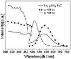
도 1은 실시예 1a, 1b 및 1c와, 실시예 10에서 제조된 형광체의 발광스펙트럼이다.
도 2는 실시예 1a 및 1c에서 제조된 형광체의 XRD 패턴 그래프이다.
도 3은 실시예 2d 및 실시예 11에서 제조된 형광체의 발광스펙트럼이다.
도 4는 실시예 2a, 2b, 2c, 2d 및 2e에서 제조된 형광체의 XRD 패턴 그래프이다.
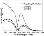
도 5는 실시예 3c 및 실시예 12에서 제조된 형광체의 발광스펙트럼이다.
도 6은 실시예 3a, 3b 및 3c에서 제조된 형광체의 XRD 패턴 그래프이다.
도 7은 실시예 4d 및 실시예 13에서 제조된 형광체의 발광스펙트럼이다.
도 8은 실시예 4a, 4b, 4c, 4d 및 4e에서 제조된 형광체의 XRD 패턴 그래프이다.
도 9는 실시예 5e 및 실시예 14에서 제조된 형광체의 발광스펙트럼이다.
도 10은 실시예 5a, 5b, 5c, 5d 및 5e에서 제조된 형광체의 XRD 패턴 그래프이다.
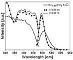
도 11은 실시예 6d 및 실시예 15에서 제조된 형광체의 발광스펙트럼이다.
도 12는 실시예 6a, 6b, 6c, 6d 및 6e에서 제조된 형광체의 XRD 패턴 그래프이다.
도 13은 실시예 7b 및 실시예 16에서 제조된 형광체의 발광스펙트럼이다.
도 14는 실시예 7a, 7b 및 7c에서 제조된 형광체의 XRD 패턴 그래프이다.
도 15는 실시예 8b 및 실시예 17에서 제조된 형광체의 발광스펙트럼이다.
도 16은 실시예 8a, 8b 및 8c에서 제조된 형광체의 XRD 패턴 그래프이다.
도 17은 실시예 9a, 9b 및 실시예 18에서 제조된 형광체의 발광스펙트럼이다.
도 18은 실시예 9a 및 9b에서 제조된 형광체의 XRD 패턴 그래프이다.
도 19는 패키지 형태의 백색 발광 다이오드의 개략도이다.
도 20은 탑 백색 발광 다이오드의 개략도이다.
도 21은 Sr2Si5N8:Eu2+및 SrSi2O2N2:Eu2+의 혼합상 형광체를 에폭시 수지 중량 대비 1:0.3 중량비 및 1:0.4 중량비로 혼합 사용하여 제작한 백색 발광 다이오드의 발광 스펙트럼을 나타낸 그래프이다.
1 is a light emission spectrum of the phosphors prepared in Examples 1a, 1b, and 1c and Example 10;
2 is an XRD pattern graph of phosphors prepared in Examples 1a and 1c.
3 is a light emission spectrum of the phosphors prepared in Examples 2d and 11;
4 is an XRD pattern graph of phosphors prepared in Examples 2a, 2b, 2c, 2d, and 2e.
5 is a light emission spectrum of the phosphors prepared in Examples 3c and 12.
6 is an XRD pattern graph of phosphors prepared in Examples 3a, 3b, and 3c.
7 is a light emission spectrum of the phosphors prepared in Examples 4d and 13.
8 is an XRD pattern graph of phosphors prepared in Examples 4a, 4b, 4c, 4d, and 4e.
9 is a light emission spectrum of the phosphors prepared in Examples 5e and 14;
10 is an XRD pattern graph of phosphors prepared in Examples 5a, 5b, 5c, 5d, and 5e.
11 is a light emission spectrum of the phosphors prepared in Example 6d and Example 15.
12 is an XRD pattern graph of phosphors prepared in Examples 6a, 6b, 6c, 6d, and 6e.
13 is a light emission spectrum of the phosphors prepared in Example 7b and Example 16.
14 is an XRD pattern graph of phosphors prepared in Examples 7a, 7b, and 7c.
15 is a light emission spectrum of the phosphors prepared in Example 8b and Example 17. FIG.
16 is an XRD pattern graph of phosphors prepared in Examples 8a, 8b, and 8c.
FIG. 17 shows emission spectra of phosphors prepared in Examples 9a, 9b and 18. FIG.
18 is a graph of XRD patterns of phosphors prepared in Examples 9a and 9b.
19 is a schematic diagram of a white light emitting diode in the form of a package.
20 is a schematic diagram of a top white light emitting diode.
FIG. 21 is a white light emission produced by mixing Sr2 Si5 N8 : Eu2+ and SrSi2 O2 N2 : Eu2+ mixed phase phosphors in a 1: 0.3 weight ratio and a 1: 0.4 weight ratio based on the weight of the epoxy resin. It is a graph showing the emission spectrum of a diode.
본 발명에 따른 질화물계 형광체의 제조방법은 과정별로 보다 세분화하면 하기와 같은 3단계 과정을 포함하여 이루어진다.The method of manufacturing the nitride-based phosphor according to the present invention comprises three steps as follows if the process is further broken down.
상기 화학식 1의 조성을 갖는 실리케이트계 전구체에 질화규소(Si3N4) 단독 화합물 또는 질화규소(Si3N4)와 이산화규소(SiO2)의 혼합물을 첨가하여 혼합하는 1단계;A step of adding and mixing a silicon nitride (Si3 N4 ) compound or a mixture of silicon nitride (Si3 N4 ) and silicon dioxide (SiO2 ) to the silicate precursor having the composition of
상기 1단계의 혼합물을 오븐에서 100℃ 내지 150℃ 온도로 건조하는 2단계; 및2 steps of drying the mixture of the first step to 100 ℃ to 150 ℃ temperature in an oven; And
상기 2단계의 건조된 혼합물을 부피비가 75 ∼ 95 : 25 ∼ 5 부피%인 질소와 수소의 혼합 가스 분위기 및1200℃ 내지 1600℃ 온도 조건하에서 소성하여, 상기 화학식 2 또는 3으로부터 선택된 단일 조성 또는 혼합 조성의 질화물계 형광체를 제조하는 3단계.The dried mixture of the second step is a mixed gas atmosphere of nitrogen and hydrogen having a volume ratio of 75 to 95:25 to 5% by volume and Baking under a temperature condition of 1200 ℃ to 1600 ℃, to produce a nitride-based phosphor of a single composition or mixed composition selected from the formula (2) or (3).
이러한 본 발명에 따른 질화물계 형광체의 제조방법을 보다 구체적으로 설명하면 하기와 같다.Hereinafter, a method of manufacturing the nitride-based phosphor according to the present invention will be described in detail.
제 1단계는 원료물질로 사용된 실리케이트계 전구체와 질화규소(Si3N4) 단독 화합물 또는 질화규소(Si3N4)와 이산화규소(SiO2)의 혼합물을 혼합하는 단계이다.The first step is a step of mixing the silicate precursor used as a raw material and a silicon nitride (Si3 N4 ) alone compound or a mixture of silicon nitride (Si3 N4 ) and silicon dioxide (SiO2 ).
본 발명이 원료물질로 사용하는 실리케이트계 전구체는 알칼리토금속과 규소를 주성분으로 포함한다. 알칼리토금속은 마그네슘(Mg), 스트론튬(Sr), 칼슘(Ca) 및 바륨(Ba) 중에서 선택된 1종 이상의 금속이 사용되며, 사용되는 알칼리토금속의 종류 및 함량 조절에 의해 형광체의 발광 파장 제어도 가능하다.The silicate precursor used as the raw material of the present invention contains alkaline earth metal and silicon as main components. Alkaline earth metal is one or more metals selected from magnesium (Mg), strontium (Sr), calcium (Ca) and barium (Ba) is used, it is also possible to control the emission wavelength of the phosphor by controlling the type and content of alkaline earth metal used Do.
또한, 상기 실리케이트계 전구체는 필요에 따라 활성제로서 유로피움(Eu2+)이 포함 또는 비포함될 수도 있다. 만약, 유로피움이 비포함된 실리케이트계 전구체를 선택 사용하는 경우에는 본 발명의 제 1단계에 따른 혼합과정에서 활성제를 추가로 포함시키도록 한다. 본 발명이 사용하는 활성제는 유로피움(Eu)을 필수성분으로 하며, 필요에 따라 유로피움(Eu)과 함께 부활성제로 이트륨(Y), 세륨(Ce), 란탄(La), 망간(Mn) 및 사마륨(Sm) 중에서 선택된 단일 또는 2종 이상의 부활성제를 추가로 사용하여 형광체의 발광 파장 및 휘도를 변화시킬 수도 있다.In addition, the silicate-based precursor may be included or not included europium (Eu2+ ) as the active agent as needed. If, in the case of using a silicate precursor that does not contain europium, the active agent may be additionally included in the mixing process according to the first step of the present invention. The active agent used in the present invention contains europium (Eu) as an essential component, and yttrium (Y), cerium (Ce), lanthanum (La), and manganese (Mn) as an inactive agent together with europium (Eu) as necessary. And a single or two or more additives selected from samarium (Sm) may be used to change the emission wavelength and luminance of the phosphor.
본 발명의 제조방법에서 사용되는 실리케이트계 전구체를 보다 구체적으로 예시하면 하기 화학식 1a, 1b, 1c, 1d, 1e, 1f, 1g, 1h, 및 1i로 각각 나타낼 수 있다.In more detail, the silicate precursors used in the production method of the present invention may be represented by the following Chemical Formulas 1a, 1b, 1c, 1d, 1e, 1f, 1g, 1h, and 1i.
[화학식 1a][Formula 1a]
(M1,M2)3-x-zSiO5-b:Eu2+z(M1, M2)3-xz SiO5-b : Eu2+z
상기 화학식 1a에서, M1 및 M2는 서로 같거나 다른 것으로서 Mg, Ca, Sr 및 Ba로 이루어지는 군에서 선택된 1종 이상의 알칼리토금속 이온이고, 0≤x≤2, 0≤b≤2,0≤z≤3 이고, 단 z≤3-x 이다.In Formula 1a, M1 and M2, which are the same as or different from each other, are one or more alkaline earth metal ions selected from the group consisting of Mg, Ca, Sr, and Ba, and 0 ≦ x ≦ 2, 0 ≦ b ≦ 2, 0 ≦ z ≦ 3, provided that z ≦ 3-x.
[화학식 1b][Chemical Formula 1b]
(M1,M2)3-zSiO5:Eu2+z(M1, M2)3-z SiO5 : Eu2+z
상기 화학식 1b에서, M1 및 M2는 서로 같거나 다른 것으로서 Mg, Ca, Sr 및 Ba로 이루어지는 군에서 선택된 1종 이상의 알칼리토금속 이온이고, 0≤z≤3 이다.In Formula 1b, M1 and M2 are the same as or different from each other, and are one or more alkaline earth metal ions selected from the group consisting of Mg, Ca, Sr, and Ba, and 0 ≦ z ≦ 3.
[화학식 1c][Formula 1c]
(M1,M2)2-zSiO4:Eu2+z(M1, M2)2-z SiO4 : Eu2+z
상기 화학식 1c에서, M1 및 M2는 서로 같거나 다른 것으로서 Mg, Ca, Sr 및 Ba로 이루어지는 군에서 선택된 1종 이상의 알칼리토금속 이온이고, 0≤z≤2 이다.In Formula 1c, M1 and M2 are the same as or different from each other and are at least one alkaline earth metal ion selected from the group consisting of Mg, Ca, Sr, and Ba, and 0 ≦ z ≦ 2.
[화학식 1d]≪ RTI ID = 0.0 &
(M1,M2)3-x-zMgSi2Ob:Eu2+z(M1, M2)3-xz MgSi2 Ob : Eu2+z
상기 화학식 1d에서, M1 및 M2는 서로 같거나 다른 것으로서 Ca, Sr 및 Ba로 이루어지는 알칼리토금속 이온과 Eu2+으로 이루어지는 군에서 선택된 1종 이상의 금속이온이고, 0≤x≤1, 7≤b≤8, 0≤z≤1 이다.In Formula 1d, M1 and M2, which are the same as or different from each other, are at least one metal ion selected from the group consisting of alkaline earth metal ions consisting of Ca, Sr and Ba, and Eu2+ , and 0 ≦ x ≦ 1, 7 ≦ b ≦ 8, 0 ≦ z ≦ 1.
[화학식 1e][Formula 1e]
(M1,M2)3-zMgSi2O8:Eu2+z(M1, M2)3-z MgSi2 O8 : Eu2+z
상기 화학식 1e에서, M1 및 M2는 서로 같거나 다른 것으로서 Ca, Sr 및 Ba로 이루어지는 군에서 선택된 1종 이상의 알칼리토금속 이온이고, 0≤z≤1 이다.In Formula 1e, M1 and M2 are the same as or different from each other, and at least one alkaline earth metal ion selected from the group consisting of Ca, Sr, and Ba, and 0 ≦ z ≦ 1.
[화학식 1f][Formula 1f]
(M1,M2)2-zMgSi2O7:Eu2+z(M1, M2)2-z MgSi2 O7 : Eu2+z
상기 화학식 1f에서, M1 및 M2는 서로 같거나 다른 것으로서 Ca, Sr 및 Ba로 이루어지는 군에서 선택된 1종 이상의 알칼리토금속 이온이고, 0≤z≤1 이다.In Formula 1f, M1 and M2, which are the same as or different from each other, are one or more alkaline earth metal ions selected from the group consisting of Ca, Sr, and Ba, and 0 ≦ z ≦ 1.
[화학식 1g][Formula 1g]
(M1,M2)8-x-zMgcSiaObXd:Eu2+z(M1, M2)8-xz Mgc Sia Ob Xd : Eu2+z
상기 화학식 1g에서, M1 및 M2는 서로 같거나 다른 것으로서 Ca, Sr 및 Ba로 이루어지는 군에서 선택된 1종 이상의 알칼리토금속 이온이고, X는 F, Cl, Br 및 I로 이루어지는 군에서 선택된 할로겐 이온이고, 0≤x≤5, 1≤a≤4, 4≤b≤16, 0≤c≤1, 0<d≤2, 0≤z≤1 이다.In Formula 1g, M1 and M2 are the same as or different from each other, at least one alkaline earth metal ion selected from the group consisting of Ca, Sr, and Ba, X is a halogen ion selected from the group consisting of F, Cl, Br, and I, 0 ≦ x ≦ 5, 1 ≦ a ≦ 4, 4 ≦ b ≦ 16, 0 ≦ c ≦ 1, 0 <d ≦ 2, and 0 ≦ z ≦ 1.
[화학식 1h][Formula 1h]
(M1,M2)3-zSiO4Cl2:Eu2+z(M1, M2)3-z SiO4 Cl2 : Eu2+z
상기 화학식 1h에서, M1 및 M2는 서로 같거나 다른 것으로서 Mg, Ca, Sr 및 Ba로 이루어지는 군에서 선택된 1종 이상의 알칼리토금속 이온이고, 0≤z≤1 이다.In Formula 1h, M1 and M2 are the same as or different from each other, and are at least one alkaline earth metal ion selected from the group consisting of Mg, Ca, Sr, and Ba, and 0 ≦ z ≦ 1.
[화학식 1i]Formula 1i]
(M1,M2)8-zMgSi4O16Cl2:Eu2+z(M1, M2)8-z MgSi4 O16 Cl2 : Eu2+z
상기 화학식 1i에서, M1 및 M2는 서로 같거나 다른 것으로서 Ca, Sr 및 Ba로 이루어지는 군에서 선택된 1종 이상의 알칼리토금속 이온이고, 0≤z≤1 이다.In Formula 1i, M1 and M2, which are the same as or different from each other, are one or more alkaline earth metal ions selected from the group consisting of Ca, Sr, and Ba, and 0 ≦ z ≦ 1.
상기한 실리케이트계 전구체와 질화규소(Si3N4) 그리고 이산화규소(SiO2) 및/또는 활성제 및/또는 부활성제를 혼합하는 방법은 당 분야에서 일반적으로 사용되는 방법으로 특별히 한정하지 않으나, 예를 들어, 막자유발, 습식 볼밀 또는 건식 볼밀 등의 방법을 이용할 수 있다. 또한, 상기 실리케이트계 전구체와 질화규소(Si3N4)의 혼합은 특별한 용매 사용 없이 분말 상태로 혼합할 수 있고, 또는 용매를 사용하여 슬러리 상태로 혼합할 수도 있다. 혼합에 사용되는 용매는 당 분야에서 일반적으로 사용되는 것으로 특별히 한정하지 않으나, 예를 들어, 증류수, 탄소수가 1 내지 4개인 저급 알콜 또는 아세톤 등을 사용할 수 있다.The method of mixing the silicate precursor with silicon nitride (Si3 N4 ) and silicon dioxide (SiO2 ) and / or the activator and / or the subsidiary agent is not particularly limited to methods generally used in the art, but examples For example, a method such as mortification, wet ball mill, or dry ball mill can be used. In addition, the silicate-based precursor and silicon nitride (Si3 N4 ) may be mixed in a powder state without using a special solvent, or may be mixed in a slurry state using a solvent. The solvent used for mixing is generally used in the art, and is not particularly limited. For example, distilled water, lower alcohols having 1 to 4 carbon atoms, acetone, or the like may be used.
제 2단계는 상기의 혼합물을 건조하는 단계이다.The second step is to dry the mixture.
상기 건조는 소성 전에 이루어지는 과정으로, 혼합물 중에 포함된 수분 및 용매를 증발 제거하기 위하여 실시한다. 상기 건조 온도는 100℃ 내지 150℃ 범위를 유지한다. 이때, 건조온도가 100℃ 미만인 경우에는 수분 및 용매가 완전히 증발하지 않고 남아 있어 소성 과정에서 부산물을 생성시킬 염려가 있으며, 건조온도가 150℃를 초과하여 고온을 유지하면 수분 및 용매가 형광체 구성 성분과 반응하여 부산물을 생성할 수 있다.The drying is a process performed before firing, and is carried out to evaporate and remove the water and the solvent contained in the mixture. The drying temperature is maintained in the range of 100 ℃ to 150 ℃. At this time, when the drying temperature is less than 100 ℃, there is a concern that the by-products are generated during the calcination process because the moisture and the solvent do not completely evaporate. And by-products can be produced.
제 3단계는 상기의 건조 혼합물을 소성하여 질화물계 형광체 분말을 제조하는 단계이다.The third step is to prepare a nitride-based phosphor powder by firing the dry mixture.
상기 소성은 질소와 수소의 혼합가스 분위기 하에서 열처리하는 바, 이미 환원이 되어있는 실리케이트계 전구체의 활성제가 산화되는 것을 방지하고, 질화물계 형광체에 환원이 이루어진 상태로 치환되게 하기 위한 단계이다. 보다 구체적으로 상기 소성은 질소와 수소가 75 ∼ 95 : 25 ∼ 5 부피%의 부피비를 이루는 혼합가스 분위기 하에서1200℃ 내지 1600℃ 온도로 열처리함으로써 이루어진다. 혼합가스의 부피비에 있어, 수소의 부피비가 5 부피% 미만인 경우에는 상기 형광체의 환원이 온전히 유지되지 않아 질화물계의 결정이 완전하게 생성되지 않을 수 있으며, 수소의 부피비가 25 부피%를 초과하는 경우에는 상기 혼합가스가 고온에서 반응하기 때문에 폭발의 위험이 있을 수 있다. 또한, 열처리 온도가 1200℃ 미만인 경우 때때로 질화물계 형광체가 생성되지 못하는 경우가 생길 수 있으며, 때로는 첨가된 질화규소(Si3N4)가 실리케이트계 전구체와 반응하지 못하고 미반응물로 남아 불순물로 작용하여 발광휘도의 감소에 따른 발광 효율이 감소하는 문제점이 발생할 수 있다. 그리고, 열처리 온도가 1600℃를 초과하는 경우 때때로 질화물계 형광체의 결정이 유리화되어 녹게 되고, 형광체 분말을 제조하기 어렵게 되어 분말의 크기를 제어하기가 어려운 문제점이 발생할 수 있다.The firing is a step for preventing the active agent of the silicate precursor, which is already reduced, from being heat-treated under a mixed gas atmosphere of nitrogen and hydrogen, and replacing the nitride-based phosphor in a reduced state. More specifically, the firing is carried out under a mixed gas atmosphere in which nitrogen and hydrogen form a volume ratio of 75 to 95:25 to 5% by volume. Heat treatment at a temperature of 1200 ° C to 1600 ° C. In the volume ratio of the mixed gas, when the volume ratio of hydrogen is less than 5% by volume, the reduction of the phosphor is not maintained intact, so that the crystal of the nitride system may not be completely produced, and when the volume ratio of hydrogen exceeds 25% by volume There may be a risk of explosion because the mixed gas reacts at a high temperature. In addition, when the heat treatment temperature is less than 1200 ° C, sometimes nitride-based phosphors may not be generated, and sometimes added silicon nitride (Si3 N4 ) does not react with the silicate precursor and remains as an unreacted substance to act as an impurity to emit light. There may be a problem that the luminous efficiency decreases due to the decrease in luminance. In addition, when the heat treatment temperature exceeds 1600 ° C., crystals of the nitride-based phosphor are sometimes vitrified and melted, and it may be difficult to manufacture the phosphor powder, which makes it difficult to control the size of the powder.
상기 소성하여 제조된 질화물계 형광체는 볼 밀 또는 제트 밀 등을 사용하여 분쇄될 수 있다. 분쇄 및 소성은 2회 이상 반복될 수도 있다. 필요하다면, 제조된 형광체를 세정할 수도 있다. 구체적으로 세정은 소성하여 얻은 형광체를 산과 접촉시키는 것을 포함하며, 때로는 세정의 결과로 형광체의 휘도가 향상되거나 또는 형광체의 온도 특성이 향상되는 효과를 기대할 수도 있다. 형광체를 산과 접촉시키는 방법은 구체적으로 산에 형광체를 침지시키는 방법, 교반하면서 산에 형광체를 침지시키는 방법, 및 습식 볼 밀에 산과 형광체를 혼합하는 방법 등이 사용될 수 있다. 좋기로는 교반을 수행하면서 산에 형광체를 침지시키는 방법이 바람직하다. 세정에 사용되는 산의 선택에 특별한 제한을 두고 있지는 않으며, 구체적으로는 아세트산, 옥살산 등의 유기산 또는 염산, 질산, 황산 등의 무기산이 사용될 수 있고, 좋기로는 염산, 질산 및 황산 중에서 선택된 무기산을 사용하는 것이고, 특히 좋기로는 염산 또는 질산을 사용하는 것이다. 세정에 사용되는 산의 수소 이온 농도는 그 취급상 바람직하게는 대략 0.001 mol/L 내지 2 mol/L 범위이다. 산의 온도는 실온(약 25℃)이며, 필요하다면, 그 산은 대략 30℃ 내지 80℃ 온도로 가열하여 사용할 수도 있다. 산과 형광체의 접촉 시간은 통상 1초 내지 약 10시간 정도이다.The nitride-based phosphor prepared by firing may be pulverized using a ball mill or a jet mill. Grinding and firing may be repeated two or more times. If necessary, the prepared phosphor may be cleaned. Specifically, the cleaning includes contacting the phosphor obtained by firing with an acid, and sometimes, as a result of the cleaning, the brightness of the phosphor may be improved or the temperature characteristic of the phosphor may be improved. Specifically, the method of contacting the phosphor with an acid may be a method of immersing the phosphor in an acid, a method of immersing the phosphor in an acid while stirring, and a method of mixing an acid and a phosphor in a wet ball mill. Preferably a method of immersing the phosphor in an acid while stirring is preferred. There is no particular restriction on the choice of acid used for washing, and in particular, organic acids such as acetic acid and oxalic acid or inorganic acids such as hydrochloric acid, nitric acid and sulfuric acid may be used, and preferably inorganic acids selected from hydrochloric acid, nitric acid and sulfuric acid. In particular, hydrochloric acid or nitric acid is used. The hydrogen ion concentration of the acid used for washing is preferably in the range of approximately 0.001 mol / L to 2 mol / L for its handling. The temperature of the acid is room temperature (about 25 ° C), and if necessary, the acid may be heated to a temperature of approximately 30 ° C to 80 ° C. The contact time of the acid and the phosphor is usually about 1 second to about 10 hours.
이상의 제조방법을 통하여 제조된 질화물계 형광체는 350 내지 550 nm 파장영역에서 여기되어, 495 내지 630 nm 파장영역에서 중심파장을 갖는 발광특성을 가진다. 또한, 본 발명의 제조방법을 통하여 제조되는 형광체는 상기 화학식 2 또는 화학식 3의 단일 조성을 가지는 형광체로 제조되거나 또는 상기 화학식 2 또는 화학식 3의 조성을 가지는 2종 이상의 형광체 혼합물로 제조될 수 있다. 따라서, 제조된 형광체의 발광 스펙트럼은 단일 발광피크 또는 다중 발광피크를 나타낼 수 있다. 다중 발광피크의 발견은 반응원료로 사용된 실리케이트계 전구체와 반응생성물로 얻어진 질화물계 형광체의 혼합물 존재로 인한 것일 수 있고, 또는 서로 다른 조성의 질화물계 형광체 혼합물의 생성으로 인한 것일 수 있다.The nitride-based phosphor prepared by the above manufacturing method is excited in a wavelength range of 350 to 550 nm, and has a light emission characteristic having a center wavelength in the wavelength range of 495 to 630 nm. In addition, the phosphor prepared by the method of the present invention may be prepared with a phosphor having a single composition of
한편, 본 발명은 상기 화학식 2 또는 3으로부터 선택된 단일 조성 또는 혼합 조성의 질화물계 형광체를 이용하여 제작된 발광 소자를 그 특징으로 한다. 본 발명에 따른 질화물계 형광체는 고연색성을 가지는 백색광 소자에 단독 사용이 가능하고, 다른 형광체와의 혼합사용이 또한 가능하다. 보다 구체적으로, 본 발명에 따른 질화물계 형광체는 우수한 색 연색성, 내구성 및 고 휘도가 요구되는, 발광 다이오드, 레이저 다이오드, 면 발광 레이저 다이오드, 무기 일렉트로루미네선스 소자, 또는 유기 일렉트로루미네센스 소자와 같은 발광 소자에 유용하게 적용될 수 있다. 발광 소자에 사용되는 질화물계 형광체의 크기는 5 내지 20 ㎛의 범위가 바람직하다. 이때, 형광체의 크기가 5 ㎛ 미만인 경우에는 휘도저하의 문제점이 발생하고, 20 ㎛ 초과인 경우에는 발광 장치에 적용이 어려운 문제점이 발생할 수도 있다.On the other hand, the present invention is characterized by a light emitting device manufactured using a nitride-based phosphor of a single composition or a mixed composition selected from the formula (2) or (3). The nitride phosphor according to the present invention can be used alone in a white light device having high color rendering property, and can also be mixed with other phosphors. More specifically, the nitride-based phosphor according to the present invention is a light emitting diode, a laser diode, a surface-emitting laser diode, an inorganic electroluminescent device, or an organic electroluminescent device, which requires excellent color rendering, durability and high brightness. It can be usefully applied to the same light emitting device. The size of the nitride phosphor used in the light emitting device is preferably in the range of 5 to 20 µm. In this case, when the size of the phosphor is less than 5 μm, a problem of deterioration of luminance may occur.
상기 발광소자의 한 예로서, 발광 다이오드는 광을 내는 광원, 상기 광원을 지지하는 기판(substrate) 및 상기 광원 주위를 몰딩한 몰딩부재를 포함하여 이루어진다. 즉, 본 발명의 질화물계 형광체와 몰딩부재인 투명 수지를 포함하는 발광소자용 코팅 형광체 조성물이 상기 발광다이오드 칩의 주위를 몰딩함으로써 발광 다이오드를 구성할 수 있다. 이때, 상기 발광소자용 코팅 형광체 조성물은 본 발명에 따른 방법에 의한 질화물계 형광체와 투명 수지를 발광 소자의 적용 분야에 따라 일정 함량비로 포함될 수 있다. 투명 수지와 질화물계 형광체의 혼합비는 1 : 0.01 내지 10 중량비, 바람직하기로는 1 : 0.1 내지 1 중량비 범위를 유지하도록 한다. 상기 투명 수지는 당 분야에서 일반적으로 사용되는 것으로 특별히 한정하지 않으나, 예를 들어, 에폭시 수지, 실리콘 수지, 폴리이미드 수지, 요소수지 및 아크릴 수지 등이 사용될 수 있다. 상기 몰딩부재에는 단일구조와 다중구조의 여부와 상관없이, 본 발명에 따른 방법에 의해 제조된 형광체가 한 가지 이상 반드시 포함된다.As an example of the light emitting device, the light emitting diode includes a light source for emitting light, a substrate supporting the light source, and a molding member molded around the light source. That is, the coating phosphor composition for a light emitting device including the nitride-based phosphor of the present invention and a transparent resin that is a molding member may form a light emitting diode by molding the periphery of the light emitting diode chip. In this case, the coating phosphor composition for the light emitting device may include a nitride-based phosphor and a transparent resin by a method according to the invention in a certain content ratio according to the application field of the light emitting device. The mixing ratio of the transparent resin and the nitride-based phosphor is maintained in a range of 1: 0.01 to 10% by weight, preferably 1: 0.1 to 1% by weight. The transparent resin is generally used in the art and is not particularly limited. For example, an epoxy resin, a silicone resin, a polyimide resin, a urea resin, an acrylic resin, or the like may be used. The molding member necessarily includes one or more phosphors produced by the method according to the present invention, regardless of whether they have a single structure or multiple structures.
이상에서 설명한 바와 같은 본 발명은 하기의 실시예 및 실험예를 통하여 더욱 상세히 설명하나, 본 발명이 속하는 기술 분야에서 통상의 지식을 가진 사람이라면, 본 발명에 따른 발광다이오드의 구성은 기술적 사상의 범위 내에서도 여러 가지의 부가, 변경 및 삭제가 얼마든지 가능함은 명백하다.
The present invention as described above will be described in more detail with reference to the following Examples and Experimental Examples, but those skilled in the art to which the present invention belongs, the configuration of the light emitting diode according to the present invention is within the scope of the technical idea It is obvious that various additions, changes, and deletions can be made within the scope.
이하, 본 발명은 하기 실시예에 의거하여 구체적으로 설명하겠는 바, 본 발명이 이에 한정되는 것은 아니다.
Hereinafter, the present invention will be described in detail based on the following examples, but the present invention is not limited thereto.
[실시예]
EXAMPLE
실시예 1 내지 18. 질화물계 형광체 분말의 제조Examples 1 to 18. Preparation of Nitride-Based Phosphor Powders
하기 표 1 또는 표 2에 나타낸 바와 같은 조성을 가지는 실리케이트계 전구체, 질화규소(Si3N4), 이산화규소(SiO2), 및 유로피움(Eu2+) 활성제를 혼합하고, 50 mL의 에탄올에 넣어 볼밀을 이용하여 1시간 동안 혼합하였다. 상기 혼합물을 100℃ 건조기에서 6시간 동안 건조시켜 에탄올을 완전히 휘발시켰다. 용매가 완전히 건조된 상기 혼합 재료는 알루미나 도가니 또는 질화보론 도가니에 넣어 1200 내지 1600℃에서 3 시간 내지 5 시간 동안 소성하였다. 이때, 수소 50 cc/min 및 질소 150 cc/min이 혼합된 혼합가스를 공급함으로써 환원분위기에서 열처리가 되도록 하였다. 소성이 완료되면, 형광체 입자의 크기가 20 μm 이하가 되도록 분쇄하여 형광체 분말을 얻었다.Silicate-based precursors having a composition as shown in Table 1 or Table 2, silicon nitride (Si3 N4 ), silicon dioxide (SiO2 ), and europium (Eu2+ ) activator were mixed and put into 50 mL of ethanol Mix for 1 hour using a ball mill. The mixture was dried in a 100 ° C. dryer for 6 hours to completely volatilize the ethanol. The mixed material in which the solvent was completely dried was placed in an alumina crucible or boron nitride crucible and calcined at 1200 to 1600 ° C. for 3 to 5 hours. At this time, by supplying a mixed gas of 50 cc / min hydrogen and 150 cc / min nitrogen was heat-treated in a reducing atmosphere. When the calcination was completed, the phosphor particles were pulverized to have a size of 20 μm or less, thereby obtaining a phosphor powder.
하기 표 1에는 유로피움(Eu2+)이 포함된 실리케이트계 전구체를 이용하여 형광체 분말을 제조한 대표적인 예를 나타낸 것이다.Table 1 shows a representative example of manufacturing a phosphor powder using a silicate precursor containing europium (Eu2+ ).
온도
(℃)Firing
Temperature
(℃)
Ba3Si6O12N2:Eu2+Ba3 Si6 O9 N4 : Eu2+
Ba3 Si6 O12 N2 : Eu2+
하기 표 2에는 유로피움(Eu2+)이 포함되지 않은 실리케이트계 전구체를 이용하여 형광체 분말을 제조한 대표적인 예를 나타낸 것이다.Table 2 shows a representative example of manufacturing a phosphor powder using a silicate-based precursor that does not contain europium (Eu2+ ).
온도
(℃)Firing
Temperature
(℃)
[실험예]
Experimental Example
실험예 1. 형광체의 광학적 특성 분석Experimental Example 1. Optical Characterization of Phosphors
상기 실시예에서 얻어진 각각의 질화물계 형광체 분말 각각에 대한 450 nm의 여기 파장에서 갖는 발광 스펙트럼과 XRD 패턴은 첨부도면 도 1 내지 도 18으로 나타내었다. 발광 파장의 스펙트럼 및 휘도는 PSI社 광발광(Photoluminescence) 장비를 사용하여 측정하였다. XRD 패턴은 Rikacu-D/max-2200v X-ray diffractometer 기기를 이용하여 측정하였다.The emission spectrum and the XRD pattern having the excitation wavelength of 450 nm for each of the nitride-based phosphor powders obtained in the above examples are shown in the accompanying drawings, FIGS. 1 to 18. The spectrum and luminance of the emission wavelength were measured using PSI Photoluminescence equipment. XRD patterns were measured using a Rikacu-D / max-2200v X-ray diffractometer instrument.
첨부도면의 발광 스펙트럼으로부터 확인되는 바와 같이, 본 발명에 따른 제조방법으로 제조된 질화물계 형광체는 450 nm 여기파장에 의하여 495 내지 620 nm의 파장 범위에서 중심파장을 갖는 발광을 함을 알 수 있다. 이것은 다른 구조의 실리케이트계 전구체에도 적용될 수 있어 다양한 색상을 구현할 수 있는 형광체 제조 방법으로 다양한 응용이 가능하다.As can be seen from the emission spectrum of the accompanying drawings, it can be seen that the nitride-based phosphor prepared by the manufacturing method according to the present invention emits light having a central wavelength in the wavelength range of 495 to 620 nm by 450 nm excitation wavelength. This can be applied to silicate-based precursors of other structures, so that various applications are possible as phosphor manufacturing methods capable of realizing various colors.
또한, 본 발명에 따른 제조방법으로 제조한 질화물계 형광체는 알칼리토금속의 종류와 함량 변화, 질화규소(Si3N4) 및 이산화규소(SiO2)의 첨가량 변화에 따라 형광체의 발광 파장이 변화되며, 부활성제의 선택적 사용에 의해서도 형광체의 발광 파장 변화 및 휘도 증가의 효과가 있음을 알 수 있다. 이에, 본 발명에 따른 각종 발광 소자에 적용하였을 때, 우수한 소비전력을 나타낼 것으로 기대된다.
In addition, the nitride-based phosphor prepared by the manufacturing method according to the present invention changes the emission wavelength of the phosphor according to the type and content of alkaline earth metal, the amount of addition of silicon nitride (Si3 N4 ) and silicon dioxide (SiO2 ), It can be seen that the selective use of the additive also has the effect of changing the emission wavelength of the phosphor and increasing the luminance. Thus, when applied to various light emitting devices according to the present invention, it is expected to exhibit excellent power consumption.
실험예 2: 백색 발광 다이오드의 제작Experimental Example 2: Fabrication of White Light Emitting Diode
첨부도면 도 19와 도 20은 패키지 형태의 백색 발광 다이오드와 탑 백색 발광 다이오드의 개략도를 나타낸 것이다. 이러한 백색 발광 다이오드는 전극을 가지며, 은(Ag) 페이스트로 접착 고정된 LED 칩을 가지며, 상기 LED 칩은 금(Au) 와이어에 의해 전극에 전기적으로 접속되고 있다. 상기 LED 칩은 홀컵 내에 수용되고, 상기 홀컵은 투명 수지인 에폭시 수지와 형광체를 1:0.3 중량비 및 1:0.4 중량비로 혼합하여 포함시켰다. 혼합한 형광체를 홀컵에 주입하여 140℃에서 경화시켰다. 이렇게 최종 제품으로 제조하였다. 이때, 도 19에서 혼합물 경화부는 리플렉터 내에 형성되었다.19 and 20 show schematic views of a white light emitting diode and a top white light emitting diode in a package form. This white light emitting diode has an electrode, and has an LED chip adhesively fixed with silver (Ag) paste, which is electrically connected to the electrode by a gold (Au) wire. The LED chip was accommodated in a hole cup, and the hole cup contained an epoxy resin, which is a transparent resin, and a phosphor in a ratio of 1: 0.3 and 1: 0.4 by weight. The mixed phosphor was injected into a hole cup and cured at 140 ° C. This was made into a final product. At this time, the mixture hardening portion in Figure 19 was formed in the reflector.
첨부도면 도 21은 상기 표 1의 실시예 1b에서 제조된 Sr2Si5N8:Eu2+및 SrSi2O2N2:Eu2+의 혼합상 형광체를 사용하여 제작된 백색 발광 다이오드에 대한 발광 스펙트럼이다.도 21에 의하면, 발광 파장 범위가 450 nm에서 700 nm 이상까지로 색 재현력이 좋은 백색 발광다이오드 구현이 가능함을 알 수 있고, 에폭시 수지와 형광체를 1:0.3 중량비 사용하여 제작된 백색 발광 다이오드가 보다 더 발광 효율이 우수함을 알 수 있다.
FIG. 21 is a view illustrating a white light emitting diode manufactured using a mixed phase phosphor of Sr2 Si5 N8 : Eu2+ and SrSi2 O2 N2 : Eu2+ prepared in Example 1b of Table 1 Emission spectrum. Referring to FIG. 21, it can be seen that a white light emitting diode having a good color reproducibility can be implemented in the emission wavelength range from 450 nm to 700 nm or more. It can be seen that the light emission efficiency is more excellent.
1 : 자외선 발광 칩2 : 은(Ag) 페이스트
3 : 삼원색 형광 물질4 : 금(Au) 와이어
5 : 에폭시6 : 리드 프레임1: ultraviolet light emitting chip 2: silver (Ag) paste
3: trichromatic fluorescent material 4: Au wire
5: epoxy 6: lead frame
Claims (17)
Translated fromKorean[화학식 1]
(M116-x-yM2y)SiaObXc:Eu2+z
상기 화학식 1에서, M1 및 M2는 서로 같거나 다른 것으로서 Mg, Ca, Sr 및 Ba로 이루어지는 군에서 선택된 1종 이상의 알칼리토금속 이온이고, X는 F, Cl, Br 및 I로 이루어지는 군에서 선택된 할로겐 이온이고, 0≤x≤16, 0≤y≤16, 0≤z≤3, 0.9<a≤6, 3≤b≤24, 0≤c≤8 이고, 단 0≤x+y≤16 이다.
Method for producing a nitride-based phosphor comprising the step of firing a silicate precursor having a composition of formula (1) with a silicon nitride (Si3 N4 ) single compound or a mixture of silicon nitride (Si3 N4 ) and silicon dioxide (SiO2 ) :
[Formula 1]
(M116-xy M2y ) Sia Ob Xc : Eu2+z
In Formula 1, M1 and M2 are the same as or different from each other, at least one alkaline earth metal ion selected from the group consisting of Mg, Ca, Sr and Ba, and X is a halogen ion selected from the group consisting of F, Cl, Br and I 0≤x≤16, 0≤y≤16, 0≤z≤3, 0.9 <a≤6, 3≤b≤24, 0≤c≤8, except that 0≤x + y≤16.
상기 화학식 1의 조성에서 z=0인 실리케이트계 전구체는 추가로 활성제로서 유로피움(Eu)을 포함시켜 소성하는 것을 특징으로 하는 질화물계 형광체의 제조방법.
The method according to claim 1,
The silicate-based precursor of z = 0 in the composition of Formula 1 is further fired by including europium (Eu) as an activator.
상기 질화물계 형광체는 하기 화학식 2로 표시되는 질화물 또는 하기 화학식 3으로 표시되는 산질화물로부터 선택된 단일 조성 또는 혼합조성을 이루고 있는 것을 특징으로 하는 질화물계 형광체의 제조방법 :
[화학식 2]
(M1,M2)2-zSi5N8:Euz
상기 화학식 2에서, M1 및 M2는 서로 같거나 다른 것으로서 Mg, Ca, Sr 및 Ba로 이루어지는 군에서 선택된 1종 이상의 알칼리토금속 이온이고,0<z≤2 이다,
[화학식 3]
(M1,M2)x-zSiaObNc:Euz
상기 화학식 3에서, M1 및 M2는 서로 같거나 다른 것으로서 Mg, Ca, Sr 및 Ba로 이루어지는 군에서 선택된 1종 이상의 알칼리토금속 이온이고, 0<x≤3, 0<z≤3, 2≤a≤6, 2≤b≤12, 0<c≤4 이고, 단 0<x-z≤3 이다.
The method according to claim 1 or 2,
The nitride-based phosphor is a method of producing a nitride-based phosphor, characterized in that a single composition or mixed composition selected from the nitride represented by the formula (2) or oxynitride represented by the formula (3):
(2)
(M1, M2)2-z Si5 N8: Euz
In Formula 2, M1 and M2 are the same as or different from each other, at least one alkaline earth metal ion selected from the group consisting of Mg, Ca, Sr, and Ba, 0 <z≤2,
(3)
(M1, M2)xz Sia Ob Nc : Euz
In Formula 3, M1 and M2 are the same as or different from each other, and are at least one alkaline earth metal ion selected from the group consisting of Mg, Ca, Sr, and Ba, and 0 <x ≦ 3, 0 <z ≦ 3, and 2 ≦ a ≦. 6, 2 <= b <= 12, 0 <c <= 4, but 0 <xz <= 3.
상기 화학식 1의 조성을 갖는 실리케이트계 전구체에 질화규소(Si3N4) 단독 화합물 또는 질화규소(Si3N4)와 이산화규소(SiO2)의 혼합물을 첨가하여 혼합하는 1단계;
상기 1단계의 혼합물을 오븐에서 100℃ 내지 150℃ 온도로 건조하는 2단계; 및
상기 2단계의 건조된 혼합물을 부피비가 75 ∼ 95 : 25 ∼ 5 부피%인 질소와 수소의 혼합 가스 분위기 및1200℃ 내지 1600℃ 온도 조건하에서 소성하여, 상기 화학식 2로 표시되는 질화물 또는 상기 화학식 3으로 표시되는 산질화물로부터 선택된 단일 조성 또는 혼합조성의 질화물계 형광체를 제조하는 3단계;
를 포함하여 이루어진 것을 특징으로 하는 질화물계 형광체의 제조방법.
The method according to claim 3,
A step of adding and mixing a silicon nitride (Si3 N4 ) compound or a mixture of silicon nitride (Si3 N4 ) and silicon dioxide (SiO2 ) to the silicate precursor having the composition of Formula 1;
2 steps of drying the mixture of the first step to 100 ℃ to 150 ℃ temperature in an oven; And
The dried mixture of the second step is a mixed gas atmosphere of nitrogen and hydrogen having a volume ratio of 75 to 95:25 to 5% by volume and Calcining at a temperature of 1200 ° C. to 1600 ° C., to prepare a nitride-based phosphor of a single composition or a mixed composition selected from the nitride represented by Formula 2 or the oxynitride represented by Formula 3;
Method for producing a nitride-based phosphor, characterized in that comprises a.
상기 화학식 1의 조성에서 z=0인 실리케이트계 전구체는 제 1단계에서 추가로 활성제로서 유로피움(Eu)을 포함시켜 혼합하는 것을 특징으로 하는 질화물계 형광체의 제조방법.
The method according to claim 4,
In the composition of Formula 1, z = 0, the silicate-based precursor is mixed with the europium (Eu) as an active agent in the first step is mixed.
상기 활성제로서 유로피움(Eu)과 함께 이트륨(Y), 세륨(Ce), 란탄(La), 망간(Mn) 및 사마륨(Sm) 중에서 선택된 단일 또는 2종 이상의 부활성제를 추가로 더 사용하는 것을 특징으로 하는 질화물계 형광체의 제조방법.
The method according to claim 2 or 5,
In addition to using europium (Eu) as an active agent further one or two or more additives selected from yttrium (Y), cerium (Ce), lanthanum (La), manganese (Mn) and samarium (Sm) A method for producing a nitride-based phosphor characterized in that.
상기 1단계에서는 증류수, 탄소수가 1 내지 4개인 알콜 및 아세톤으로 이루어진 군으로부터 선택된 단일 용매 또는 2종 이상의 혼합용매를 사용하여 혼합하는 것을 특징으로 하는 질화물계 형광체의 제조방법.
The method according to claim 4,
In the first step, a method of producing a nitride-based phosphor, characterized in that the mixing using a single solvent or two or more mixed solvents selected from the group consisting of distilled water, alcohol having 1 to 4 carbon atoms and acetone.
상기 실리케이트계 전구체는 하기 화학식 1a의 조성을 가지는 것을 특징으로 하는 질화물계 형광체의 제조방법 :
[화학식 1a]
(M1,M2)3-x-zSiO5-b:Eu2+z
상기 화학식 1a에서, M1 및 M2는 서로 같거나 다른 것으로서 Mg, Ca, Sr 및 Ba로 이루어지는 군에서 선택된 1종 이상의 알칼리토금속 이온이고, 0≤x≤2, 0≤b≤2, 0≤z≤3 이다.
The method according to claim 1,
The silicate-based precursor manufacturing method of the nitride-based phosphor, characterized in that having the composition of the formula (1a):
[Formula 1a]
(M1, M2)3-xz SiO5-b : Eu2+z
In Formula 1a, M1 and M2, which are the same as or different from each other, are one or more alkaline earth metal ions selected from the group consisting of Mg, Ca, Sr, and Ba, and 0 ≦ x ≦ 2, 0 ≦ b ≦ 2, and 0 ≦ z ≦. 3
상기 실리케이트계 전구체는 하기 화학식 1b의 조성을 가지는 것을 특징으로 하는 질화물계 형광체의 제조방법 :
[화학식 1b]
(M1,M2)3-zSiO5:Eu2+z
상기 화학식 1b에서, M1 및 M2는 서로 같거나 다른 것으로서 Mg, Ca, Sr 및 Ba로 이루어지는 군에서 선택된 1종 이상의 알칼리토금속 이온이고, 0≤z≤3이다.
The method according to claim 8,
The silicate-based precursor is a method for producing a nitride-based phosphor, characterized in that having the composition of Formula 1b:
[Chemical Formula 1b]
(M1, M2)3-z SiO5 : Eu2+z
In Formula 1b, M1 and M2 are the same as or different from each other, and are one or more alkaline earth metal ions selected from the group consisting of Mg, Ca, Sr, and Ba, and 0 ≦ z ≦ 3.
상기 실리케이트계 전구체는 하기 화학식 1c의 조성을 가지는 것을 특징으로 하는 질화물계 형광체의 제조방법 :
[화학식 1c]
(M1,M2)2-zSiO4:Eu2+z
상기 화학식 1c에서, M1 및 M2는 서로 같거나 다른 것으로서 Mg, Ca, Sr 및 Ba로 이루어지는 군에서 선택된 1종 이상의 알칼리토금속 이온이고, 0≤z≤2 이다.
The method according to claim 8,
The silicate-based precursor is a method for producing a nitride-based phosphor, characterized in that having the composition of Formula 1c:
[Formula 1c]
(M1, M2)2-z SiO4 : Eu2+z
In Formula 1c, M1 and M2 are the same as or different from each other and are at least one alkaline earth metal ion selected from the group consisting of Mg, Ca, Sr, and Ba, and 0 ≦ z ≦ 2.
상기 실리케이트계 전구체는 하기 화학식 1d의 조성을 가지는 것을 특징으로 하는 질화물계 형광체의 제조방법 :
[화학식 1d]
(M1,M2)3-x-zMgSi2Ob:Eu2+z
상기 화학식 1d에서, M1 및 M2는 서로 같거나 다른 것으로서 Ca, Sr 및 Ba로 이루어지는 알칼리토금속 이온과 Eu2+으로 이루어지는 군에서 선택된 1종 이상의 금속이온이고, 0≤x≤1, 7≤b≤8, 0≤z≤1 이다.
The method according to claim 1,
The silicate precursor is a method for producing a nitride-based phosphor, characterized in that having the composition of the formula 1d:
[Formula 1d]
(M1, M2)3-xz MgSi2 Ob : Eu2+z
In Formula 1d, M1 and M2, which are the same as or different from each other, are at least one metal ion selected from the group consisting of alkaline earth metal ions consisting of Ca, Sr and Ba, and Eu2+ , and 0 ≦ x ≦ 1, 7 ≦ b ≦ 8, 0 ≦ z ≦ 1.
상기 실리케이트계 전구체는 하기 화학식 1e의 조성을 가지는 것을 특징으로 하는 질화물계 형광체의 제조방법 :
[화학식 1e]
(M1,M2)3-zMgSi2O8:Eu2+z
상기 화학식 1e에서, M1 및 M2는 서로 같거나 다른 것으로서 Ca, Sr 및 Ba로 이루어지는 군에서 선택된 1종 이상의 알칼리토금속 이온이고, 0≤z≤1 이다.
The method of claim 11,
The silicate-based precursor is a method for producing a nitride-based phosphor, characterized in that having the composition of Formula 1e:
[Formula 1e]
(M1, M2)3-z MgSi2 O8 : Eu2+z
In Formula 1e, M1 and M2 are the same as or different from each other, and at least one alkaline earth metal ion selected from the group consisting of Ca, Sr, and Ba, and 0 ≦ z ≦ 1.
상기 실리케이트계 전구체는 하기 화학식 1f의 조성을 가지는 것을 특징으로 하는 질화물계 형광체의 제조방법 :
[화학식 1f]
(M1,M2)2-zMgSi2O7:Eu2+z
상기 화학식 1f에서, M1 및 M2는 서로 같거나 다른 것으로서 Ca, Sr 및 Ba로 이루어지는 군에서 선택된 1종 이상의 알칼리토금속 이온이고, 0≤z≤1 이다.
The method of claim 11,
The silicate-based precursor is a method for producing a nitride-based phosphor, characterized in that having the composition of formula 1f:
[Formula 1f]
(M1, M2)2-z MgSi2 O7 : Eu2+z
In Formula 1f, M1 and M2, which are the same as or different from each other, are one or more alkaline earth metal ions selected from the group consisting of Ca, Sr, and Ba, and 0 ≦ z ≦ 1.
상기 실리케이트계 전구체는 하기 화학식 1g의 조성을 가지는 것을 특징으로 하는 질화물계 형광체의 제조방법 :
[화학식 1g]
(M1,M2)8-x-zMgcSiaObXd:Eu2+z
상기 화학식 1g에서, M1 및 M2는 서로 같거나 다른 것으로서 Ca, Sr 및 Ba로 이루어지는 군에서 선택된 1종 이상의 알칼리토금속 이온이고, X는 F, Cl, Br 및 I로 이루어지는 군에서 선택된 할로겐 이온이고, 0≤x≤5, 1≤a≤4, 4≤b≤16, 0≤c≤1, 0<d≤2, 0≤z≤1 이다.
The method according to claim 1,
The silicate-based precursor is a method for producing a nitride-based phosphor, characterized in that having the composition of the formula 1g:
[Formula 1g]
(M1, M2)8-xz Mgc Sia Ob Xd : Eu2+z
In Formula 1g, M1 and M2 are the same as or different from each other, at least one alkaline earth metal ion selected from the group consisting of Ca, Sr, and Ba, X is a halogen ion selected from the group consisting of F, Cl, Br, and I, 0 ≦ x ≦ 5, 1 ≦ a ≦ 4, 4 ≦ b ≦ 16, 0 ≦ c ≦ 1, 0 <d ≦ 2, and 0 ≦ z ≦ 1.
상기 실리케이트계 전구체는 하기 화학식 1h의 조성을 가지는 것을 특징으로 하는 질화물계 형광체의 제조방법 :
[화학식 1h]
(M1,M2)3-zSiO4Cl2:Eu2+z
상기 화학식 1h에서, M1 및 M2는 서로 같거나 다른 것으로서 Mg, Ca, Sr 및 Ba로 이루어지는 군에서 선택된 1종 이상의 알칼리토금속 이온이고, 0≤z≤1 이다.
The method according to claim 14,
The silicate precursor is a method for producing a nitride-based phosphor, characterized in that having the composition of the formula 1h:
[Formula 1h]
(M1, M2)3-z SiO4 Cl2 : Eu2+z
In Formula 1h, M1 and M2 are the same as or different from each other, and are at least one alkaline earth metal ion selected from the group consisting of Mg, Ca, Sr, and Ba, and 0 ≦ z ≦ 1.
상기 실리케이트계 전구체는 하기 화학식 1i의 조성을 가지는 것을 특징으로 하는 질화물계 형광체의 제조방법 :
[화학식 1i]
(M1,M2)8-zMgSi4O16Cl2:Eu2+z
상기 화학식 1i에서, M1 및 M2는 서로 같거나 다른 것으로서 Ca, Sr 및 Ba로 이루어지는 군에서 선택된 1종 이상의 알칼리토금속 이온이고, 0≤z≤1 이다.
The method according to claim 14,
The silicate-based precursor is a method for producing a nitride-based phosphor, characterized in that having the composition of Formula 1i:
Formula 1i]
(M1, M2)8-z MgSi4 O16 Cl2 : Eu2+z
In Formula 1i, M1 and M2, which are the same as or different from each other, are one or more alkaline earth metal ions selected from the group consisting of Ca, Sr, and Ba, and 0 ≦ z ≦ 1.
하기 화학식 2로 표시되는 질화물 또는 하기 화학식 3으로 표시되는 산질화물로부터 선택된 단일 조성 또는 혼합조성을 이루고 있는 것을 특징으로 하는 질화물계 형광체 :
[화학식 2]
(M1,M2)2-zSi5N8:Euz
상기 화학식 2에서, M1 및 M2는 서로 같거나 다른 것으로서 Mg, Ca, Sr 및 Ba로 이루어지는 군에서 선택된 1종 이상의 알칼리토금속 이온이고, 0<z≤2 이다,
[화학식 3]
(M1,M2)x-ZSiaObNc:EuZ
상기 화학식 3에서, M1 및 M2는 서로 같거나 다른 것으로서 Mg, Ca, Sr 및 Ba로 이루어지는 군에서 선택된 1종 이상의 알칼리토금속 이온이고, 0<x≤3, 0<z≤3, 2≤a≤6, 2≤b≤12, 0<c≤4 이고, 단 0<x-z≤3 이다.Prepared according to claim 1,
A nitride-based phosphor, comprising a single composition or a mixed composition selected from the nitride represented by the formula (2) or the oxynitride represented by the formula (3):
(2)
(M1, M2)2-z Si5 N8: Euz
In Formula 2, M1 and M2 are the same as or different from each other and at least one alkaline earth metal ion selected from the group consisting of Mg, Ca, Sr, and Ba, wherein 0 <z ≦ 2.
(3)
(M1, M2)xZ Sia Ob Nc : EuZ
In Formula 3, M1 and M2 are the same as or different from each other, and are at least one alkaline earth metal ion selected from the group consisting of Mg, Ca, Sr, and Ba, and 0 <x ≦ 3, 0 <z ≦ 3, and 2 ≦ a ≦. 6, 2 <= b <= 12, 0 <c <= 4, but 0 <xz <= 3.
Applications Claiming Priority (2)
| Application Number | Priority Date | Filing Date | Title |
|---|---|---|---|
| KR20100017302 | 2010-02-25 | ||
| KR1020100017302 | 2010-02-25 |
Publications (2)
| Publication Number | Publication Date |
|---|---|
| KR20110097735Atrue KR20110097735A (en) | 2011-08-31 |
| KR101196847B1 KR101196847B1 (en) | 2012-11-01 |
Family
ID=44507448
Family Applications (1)
| Application Number | Title | Priority Date | Filing Date |
|---|---|---|---|
| KR1020110017381AExpired - Fee RelatedKR101196847B1 (en) | 2010-02-25 | 2011-02-25 | The manufacturing method for nitride phosphor using silicate based precursor |
Country Status (2)
| Country | Link |
|---|---|
| KR (1) | KR101196847B1 (en) |
| WO (1) | WO2011105836A2 (en) |
Cited By (4)
| Publication number | Priority date | Publication date | Assignee | Title |
|---|---|---|---|---|
| WO2013058478A1 (en)* | 2011-10-17 | 2013-04-25 | 한국과학기술원 | Oxide-based green phosphor and method for manufacturing same, and white led using same |
| KR20130063412A (en)* | 2011-12-06 | 2013-06-14 | 엘지이노텍 주식회사 | Phosphor and method of fabricating phosphor |
| KR101389089B1 (en)* | 2011-06-16 | 2014-04-29 | 한국화학연구원 | Method of manufacturing silicon nitride phosphor using metal silicon oxynitride phosphor |
| KR101639992B1 (en)* | 2015-06-04 | 2016-07-15 | 한국화학연구원 | Manufacturing method of oxynitride phosphor using alkaline earth metal silicates |
Family Cites Families (4)
| Publication number | Priority date | Publication date | Assignee | Title |
|---|---|---|---|---|
| EP1104799A1 (en)* | 1999-11-30 | 2001-06-06 | Patent-Treuhand-Gesellschaft für elektrische Glühlampen mbH | Red emitting luminescent material |
| TWI359187B (en)* | 2003-11-19 | 2012-03-01 | Panasonic Corp | Method for preparing nitridosilicate-based compoun |
| JP2006257385A (en)* | 2004-09-09 | 2006-09-28 | Showa Denko Kk | Oxynitride phosphor and method for producing the same |
| JP4756261B2 (en)* | 2005-01-27 | 2011-08-24 | 独立行政法人物質・材料研究機構 | Phosphor, method for producing the same, and light emitting device |
- 2011
- 2011-02-24WOPCT/KR2011/001304patent/WO2011105836A2/enactiveApplication Filing
- 2011-02-25KRKR1020110017381Apatent/KR101196847B1/ennot_activeExpired - Fee Related
Cited By (4)
| Publication number | Priority date | Publication date | Assignee | Title |
|---|---|---|---|---|
| KR101389089B1 (en)* | 2011-06-16 | 2014-04-29 | 한국화학연구원 | Method of manufacturing silicon nitride phosphor using metal silicon oxynitride phosphor |
| WO2013058478A1 (en)* | 2011-10-17 | 2013-04-25 | 한국과학기술원 | Oxide-based green phosphor and method for manufacturing same, and white led using same |
| KR20130063412A (en)* | 2011-12-06 | 2013-06-14 | 엘지이노텍 주식회사 | Phosphor and method of fabricating phosphor |
| KR101639992B1 (en)* | 2015-06-04 | 2016-07-15 | 한국화학연구원 | Manufacturing method of oxynitride phosphor using alkaline earth metal silicates |
Also Published As
| Publication number | Publication date |
|---|---|
| WO2011105836A2 (en) | 2011-09-01 |
| KR101196847B1 (en) | 2012-11-01 |
| WO2011105836A3 (en) | 2012-01-05 |
Similar Documents
| Publication | Publication Date | Title |
|---|---|---|
| KR101131648B1 (en) | Highly efficient led-based illumination system featuring improved color rendering | |
| EP1749074B1 (en) | Light-emitting device using phosphor composition | |
| JP5517037B2 (en) | Phosphor, method for manufacturing the same, and light emitting device using the same | |
| CN101288342B (en) | Lighting system including ceramic luminescence converters | |
| EP2428544A1 (en) | Red light-emitting fluorescent substance and light-emitting device employing the same | |
| KR101390908B1 (en) | (Oxy) nitride phosphors and white light emitting devices containing the same | |
| KR101172143B1 (en) | OXYNITRIDE-BASED PHOSPHORS COMPOSING OF SiON ELEMENT FOR WHITE LEDs, MANUFACTURING METHOD THEREOF AND LEDs USING THE SAME | |
| JP2006514152A (en) | Strontium silicate phosphor, manufacturing method thereof, and light emitting diode using the same | |
| KR100666211B1 (en) | Silicate Phosphors for UV and Long-wavelength Excitation | |
| JP2012500313A (en) | Alpha-sialon phosphor | |
| KR20120029165A (en) | Green phosphors, method for preparing the same and white light emitting devices including the same | |
| KR101196847B1 (en) | The manufacturing method for nitride phosphor using silicate based precursor | |
| KR101196845B1 (en) | Halo-Metalnitridosilicate phosphor and Synthesis method thereof | |
| JP5818109B2 (en) | (Halo) silicate phosphor and method for producing the same | |
| KR20130080849A (en) | Light-emitting material of nitrogen compound, preparation process thereof and illumination source manufactured therefrom | |
| CN101448915B (en) | Phosphor material, coating phosphor composition, method of preparing phosphor material and light emitting device | |
| KR20110082837A (en) | Nitride phosphor, its manufacturing method and white light emitting element using the same | |
| EP2202284B1 (en) | Nitride red phosphors and white light emitting diode using rare-earth-doped nitride red phosphors | |
| KR100902415B1 (en) | Halosilicate Phosphor and Method for Producing the Same | |
| KR100658458B1 (en) | Yellow red phosphor, white LED element and yellow red LED element using same | |
| US10081763B2 (en) | Oxynitride fluorescent material, method for preparing same, and light emitting device package using same | |
| KR100906923B1 (en) | Phosphor, coated phosphor composition, phosphor manufacturing method and light emitting device |
Legal Events
| Date | Code | Title | Description |
|---|---|---|---|
| A201 | Request for examination | ||
| PA0109 | Patent application | St.27 status event code:A-0-1-A10-A12-nap-PA0109 | |
| PA0201 | Request for examination | St.27 status event code:A-1-2-D10-D11-exm-PA0201 | |
| PG1501 | Laying open of application | St.27 status event code:A-1-1-Q10-Q12-nap-PG1501 | |
| PE0902 | Notice of grounds for rejection | St.27 status event code:A-1-2-D10-D21-exm-PE0902 | |
| E13-X000 | Pre-grant limitation requested | St.27 status event code:A-2-3-E10-E13-lim-X000 | |
| P11-X000 | Amendment of application requested | St.27 status event code:A-2-2-P10-P11-nap-X000 | |
| P13-X000 | Application amended | St.27 status event code:A-2-2-P10-P13-nap-X000 | |
| E701 | Decision to grant or registration of patent right | ||
| PE0701 | Decision of registration | St.27 status event code:A-1-2-D10-D22-exm-PE0701 | |
| GRNT | Written decision to grant | ||
| PR0701 | Registration of establishment | St.27 status event code:A-2-4-F10-F11-exm-PR0701 | |
| PR1002 | Payment of registration fee | St.27 status event code:A-2-2-U10-U11-oth-PR1002 Fee payment year number:1 | |
| PG1601 | Publication of registration | St.27 status event code:A-4-4-Q10-Q13-nap-PG1601 | |
| PR1001 | Payment of annual fee | St.27 status event code:A-4-4-U10-U11-oth-PR1001 Fee payment year number:4 | |
| R17-X000 | Change to representative recorded | St.27 status event code:A-5-5-R10-R17-oth-X000 | |
| FPAY | Annual fee payment | Payment date:20161006 Year of fee payment:5 | |
| PR1001 | Payment of annual fee | St.27 status event code:A-4-4-U10-U11-oth-PR1001 Fee payment year number:5 | |
| R18-X000 | Changes to party contact information recorded | St.27 status event code:A-5-5-R10-R18-oth-X000 | |
| FPAY | Annual fee payment | Payment date:20171016 Year of fee payment:6 | |
| PR1001 | Payment of annual fee | St.27 status event code:A-4-4-U10-U11-oth-PR1001 Fee payment year number:6 | |
| FPAY | Annual fee payment | Payment date:20181015 Year of fee payment:7 | |
| PR1001 | Payment of annual fee | St.27 status event code:A-4-4-U10-U11-oth-PR1001 Fee payment year number:7 | |
| PC1903 | Unpaid annual fee | St.27 status event code:A-4-4-U10-U13-oth-PC1903 Not in force date:20191027 Payment event data comment text:Termination Category : DEFAULT_OF_REGISTRATION_FEE | |
| PC1903 | Unpaid annual fee | St.27 status event code:N-4-6-H10-H13-oth-PC1903 Ip right cessation event data comment text:Termination Category : DEFAULT_OF_REGISTRATION_FEE Not in force date:20191027 | |
| P22-X000 | Classification modified | St.27 status event code:A-4-4-P10-P22-nap-X000 |