KR20110082685A - A preamble generation method of a multi-user multi-input / output system, a data transmission device and a terminal employing the method - Google Patents
A preamble generation method of a multi-user multi-input / output system, a data transmission device and a terminal employing the methodDownload PDFInfo
- Publication number
- KR20110082685A KR20110082685AKR1020100002541AKR20100002541AKR20110082685AKR 20110082685 AKR20110082685 AKR 20110082685AKR 1020100002541 AKR1020100002541 AKR 1020100002541AKR 20100002541 AKR20100002541 AKR 20100002541AKR 20110082685 AKR20110082685 AKR 20110082685A
- Authority
- KR
- South Korea
- Prior art keywords
- vht
- field
- sta
- transmitted
- ltf
- Prior art date
- Legal status (The legal status is an assumption and is not a legal conclusion. Google has not performed a legal analysis and makes no representation as to the accuracy of the status listed.)
- Ceased
Links
Images


Classifications
- H—ELECTRICITY
- H04—ELECTRIC COMMUNICATION TECHNIQUE
- H04B—TRANSMISSION
- H04B7/00—Radio transmission systems, i.e. using radiation field
- H04B7/02—Diversity systems; Multi-antenna system, i.e. transmission or reception using multiple antennas
- H04B7/04—Diversity systems; Multi-antenna system, i.e. transmission or reception using multiple antennas using two or more spaced independent antennas
- H04B7/0413—MIMO systems
- H04B7/0452—Multi-user MIMO systems
- H—ELECTRICITY
- H04—ELECTRIC COMMUNICATION TECHNIQUE
- H04L—TRANSMISSION OF DIGITAL INFORMATION, e.g. TELEGRAPHIC COMMUNICATION
- H04L25/00—Baseband systems
- H04L25/02—Details ; arrangements for supplying electrical power along data transmission lines
- H04L25/0202—Channel estimation
- H04L25/0224—Channel estimation using sounding signals
- H04L25/0226—Channel estimation using sounding signals sounding signals per se
- H—ELECTRICITY
- H04—ELECTRIC COMMUNICATION TECHNIQUE
- H04B—TRANSMISSION
- H04B7/00—Radio transmission systems, i.e. using radiation field
- H04B7/02—Diversity systems; Multi-antenna system, i.e. transmission or reception using multiple antennas
- H04B7/04—Diversity systems; Multi-antenna system, i.e. transmission or reception using multiple antennas using two or more spaced independent antennas
- H04B7/06—Diversity systems; Multi-antenna system, i.e. transmission or reception using multiple antennas using two or more spaced independent antennas at the transmitting station
- H04B7/0697—Diversity systems; Multi-antenna system, i.e. transmission or reception using multiple antennas using two or more spaced independent antennas at the transmitting station using spatial multiplexing
- H—ELECTRICITY
- H04—ELECTRIC COMMUNICATION TECHNIQUE
- H04L—TRANSMISSION OF DIGITAL INFORMATION, e.g. TELEGRAPHIC COMMUNICATION
- H04L25/00—Baseband systems
- H04L25/02—Details ; arrangements for supplying electrical power along data transmission lines
- H04L25/0202—Channel estimation
- H04L25/0204—Channel estimation of multiple channels
- H—ELECTRICITY
- H04—ELECTRIC COMMUNICATION TECHNIQUE
- H04L—TRANSMISSION OF DIGITAL INFORMATION, e.g. TELEGRAPHIC COMMUNICATION
- H04L27/00—Modulated-carrier systems
- H04L27/02—Amplitude-modulated carrier systems, e.g. using on-off keying; Single sideband or vestigial sideband modulation
- H04L27/08—Amplitude regulation arrangements
- H—ELECTRICITY
- H04—ELECTRIC COMMUNICATION TECHNIQUE
- H04L—TRANSMISSION OF DIGITAL INFORMATION, e.g. TELEGRAPHIC COMMUNICATION
- H04L27/00—Modulated-carrier systems
- H04L27/26—Systems using multi-frequency codes
- H04L27/2601—Multicarrier modulation systems
- H04L27/2602—Signal structure
- H04L27/261—Details of reference signals
- H04L27/2613—Structure of the reference signals
- H—ELECTRICITY
- H04—ELECTRIC COMMUNICATION TECHNIQUE
- H04L—TRANSMISSION OF DIGITAL INFORMATION, e.g. TELEGRAPHIC COMMUNICATION
- H04L27/00—Modulated-carrier systems
- H04L27/26—Systems using multi-frequency codes
- H04L27/2601—Multicarrier modulation systems
- H04L27/2602—Signal structure
- H04L27/2605—Symbol extensions, e.g. Zero Tail, Unique Word [UW]
- H—ELECTRICITY
- H04—ELECTRIC COMMUNICATION TECHNIQUE
- H04L—TRANSMISSION OF DIGITAL INFORMATION, e.g. TELEGRAPHIC COMMUNICATION
- H04L27/00—Modulated-carrier systems
- H04L27/26—Systems using multi-frequency codes
- H04L27/2601—Multicarrier modulation systems
- H04L27/2647—Arrangements specific to the receiver only
- H—ELECTRICITY
- H04—ELECTRIC COMMUNICATION TECHNIQUE
- H04L—TRANSMISSION OF DIGITAL INFORMATION, e.g. TELEGRAPHIC COMMUNICATION
- H04L5/00—Arrangements affording multiple use of the transmission path
- H04L5/0001—Arrangements for dividing the transmission path
- H04L5/0014—Three-dimensional division
- H04L5/0023—Time-frequency-space
- H—ELECTRICITY
- H04—ELECTRIC COMMUNICATION TECHNIQUE
- H04L—TRANSMISSION OF DIGITAL INFORMATION, e.g. TELEGRAPHIC COMMUNICATION
- H04L5/00—Arrangements affording multiple use of the transmission path
- H04L5/003—Arrangements for allocating sub-channels of the transmission path
- H04L5/0048—Allocation of pilot signals, i.e. of signals known to the receiver
Landscapes
- Engineering & Computer Science (AREA)
- Signal Processing (AREA)
- Computer Networks & Wireless Communication (AREA)
- Power Engineering (AREA)
- Radio Transmission System (AREA)
- Mobile Radio Communication Systems (AREA)
Abstract
Translated fromKoreanDescription
Translated fromKoreanMU-MIMO 시스템에서 전송 프레임에 포함되는 프리엠블 생성 방법 및 상기 방법이 채용된 데이터 전송 장치와 단말이 개시된다.Disclosed are a preamble generation method included in a transmission frame in a MU-MIMO system, and a data transmission apparatus and a terminal employing the method.
데이터 스루풋(throughput)은 무선 통신의 중요한 이슈 중 하나이다. 특히, 근거리 통신망의 경우 사용자 수가 크게 증가하고, 음성/비디오 스트리밍 등 다양한 어플리케이션의 확대 등으로 스루풋 향상이 더욱 중요한 이슈가 되고 있다.Data throughput is one of the important issues of wireless communication. In particular, in the local area network, the number of users is greatly increased, and the improvement of throughput is becoming more important due to the expansion of various applications such as voice / video streaming.
데이터 스루풋을 향상시키기 위해서, 채널의 대역폭(bandwidth)을 늘리는 방법을 이용할 수 있다. 하지만 제한된 주파수 자원으로 인해 채널의 사용 대역폭 확장에는 한계가 있다. 따라서, 최근 주파수 자원의 증가 없이 데이터 스루풋을 향상시키기 위해 다중 입출력 기술이 활발히 연구되고 있으며, 3GPP LTE, IEEE 802.16e 등의 이동통신 및 802.11n과 같은 무선랜 관련 표준에도 채택되어 사용되고 있다. In order to improve data throughput, a method of increasing the bandwidth of a channel may be used. However, due to the limited frequency resources, there is a limit to expanding the bandwidth used by the channel. Accordingly, in recent years, multiple input / output technologies have been actively studied to improve data throughput without increasing frequency resources, and have been adopted and used in mobile communication standards such as 3GPP LTE, IEEE 802.16e, and WLAN-related standards such as 802.11n.
이동통신망에 접속하는 사용자와 적용 어플리케이션 수의 증가로 인해 사용자 분포 및 사용자 간 트래픽(traffic) 특성이 다양화 되고 있다. 또한 적용 애플리케이션과 사용자 간 서비스 품질(Quality of Service; QoS) 제공의 중요성이 더욱 부각되고 있다. 그로 인해, 넓은 채널 대역폭과 다중 입출력 기술의 적용으로 향상된 데이터 스루풋을 사용자에게 유연하게 할당할 수 있는 다중접속 기술의 개발이 요청되고 있다.Due to the increase in the number of users and applications applied to the mobile communication network, the distribution of users and traffic characteristics between users are diversified. In addition, the importance of providing quality of service (QoS) between the application and the user is becoming more important. Therefore, there is a demand for the development of a multiple access technology that can flexibly allocate improved data throughput to a user by applying a wide channel bandwidth and multiple input / output technologies.
최근, 이러한 요청에 따라 단일 전송 장치가 다수의 단말(STA)로 서로 다른 시그널을 동시에 전송함으로써, 무선 자원을 공유하는 다중사용자 다중 입력 다중 출력(Multi-User Multi-Input Multi-Output; MU-MIMO) 기술이 제안되고 있다. MU-MIMO 방식은 차세대 이동통신 표준인 802.16m 및 LTE-Advanced 표준에도 채택되었을 뿐만 아니라, 차세대 무선랜 기술인 802.11ac 표준의 적용에도 긍정적으로 고려되고 있다.Recently, in response to such a request, a single transmitting device simultaneously transmits different signals to a plurality of terminals (STAs), whereby multi-user multi-input multi-output (MU-MIMO) sharing radio resources. ) Technology has been proposed. The MU-MIMO method is not only adopted in the 802.16m and LTE-Advanced standards, which are the next generation mobile communication standards, but also positively considered in the application of the 802.11ac standard, the next generation WLAN technology.
본 명세서에서는 MU-MIMO 방식을 지원하는 프레임의 프리엠블(preamble) 생성 방법 및 그 구조의 일실시예를 제안한다. 제안된 프리엠블 구조를 이용하여 각 STA에서 공간분할다중접속(Space Divisional Multiple Access; SDMA) 프리코딩된 스트림들의 채널 정보를 추정할 수 있다.In this specification, a preamble generation method of a frame supporting the MU-MIMO scheme and an embodiment of the structure thereof are proposed. By using the proposed preamble structure, channel information of Space Divisional Multiple Access (SDMA) precoded streams can be estimated in each STA.
본 발명의 일측에 따른 데이터 전송 장치는, 하나 이상의 단말로 전송되는 하나 이상의 시공간 스트림에 적어도 하나의 VHT-LTF 시퀀스를 포함시켜 전송하되, 상기 VHT-LTF 시퀀스는 동일한 크기를 갖는다.According to an embodiment of the present invention, a data transmission apparatus includes at least one VHT-LTF sequence in one or more space-time streams transmitted to one or more terminals, but the VHT-LTF sequence has the same size.
MU-MIMO 시스템의 채널 추정을 효과적으로 수행할 수 있는 프리엠블 생성 방법 및 이를 이용한 데이터 전송 장치와 단말이 제공된다.A preamble generation method capable of effectively performing channel estimation of an MU-MIMO system, and a data transmission apparatus and a terminal using the same are provided.
특히, 채널 추정 오버헤드(overhead)를 최소화하고, STA 별로 할당된 STS 정보가 미리 알려져 있지 않더라도 STA에서 채널 추정이 가능한 프리엠블 생성 방법이 제공된다.In particular, a method of generating a preamble that minimizes channel estimation overhead and enables channel estimation in an STA even if STS information allocated for each STA is not known in advance is provided.
또한, 데이터 전송 장치와 STA 간 채널 추정뿐 아니라, 다른 STA로 전송되는 간섭 정보도 추정할 수 있는 프리앰블 생성 방법이 제공된다.In addition, a preamble generation method capable of estimating interference information transmitted to another STA as well as channel estimation between the data transmission apparatus and the STA is provided.
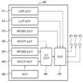
도 1은 802.11ac에 적용 가능한 MU-MIMO(Multi-User Multi-Input Multi-Output)를 지원하는 프레임 구조의 예를 도시한다.
도 2는 본 발명의 일측에 따른 MU-MIMO 방식을 이용한 프레임 전송의 일례를 도시한 도면이다.
도 3는 본 발명의 일측에 따른 MU-MIMO를 지원하는 프레임의 시공간 스트림(STS) 구조를 도시한 도면이다.
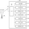
도 4는 본 발명의 일실시예에 따른 데이터 전송 장치의 구조를 도시한 블록도이다.
도 5는 본 발명의 일실시예에 따른 STA의 구조를 도시한 블록도이다.
도 6은 본 발명의 일실시예에 따른 데이터 전송 장치의 데이터 전송 방법을 도시한 순서도이다.1 shows an example of a frame structure supporting multi-user multi-input multi-output (MU-MIMO) applicable to 802.11ac.
2 is a diagram illustrating an example of frame transmission using the MU-MIMO scheme according to an embodiment of the present invention.
3 is a diagram illustrating a space-time stream (STS) structure of a frame supporting MU-MIMO according to an embodiment of the present invention.
4 is a block diagram showing the structure of a data transmission apparatus according to an embodiment of the present invention.
5 is a block diagram illustrating a structure of an STA according to an embodiment of the present invention.
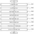
6 is a flowchart illustrating a data transmission method of a data transmission apparatus according to an embodiment of the present invention.
이하, 첨부된 도면들에 기재된 내용들을 참조하여 본 발명에 따른 실시예를 상세하게 설명한다. 다만, 본 발명이 실시예들에 의해 제한되거나 한정되는 것은 아니다. 각 도면에 제시된 동일한 참조부호는 동일한 부재를 나타낸다.Hereinafter, with reference to the contents described in the accompanying drawings will be described in detail an embodiment according to the present invention. However, the present invention is not limited to or limited by the embodiments. Like reference numerals in the drawings denote like elements.
본 명세서에서는 MU-MIMO를 지원하는 프레임의 프리엠블 구조 및 전송 제어 정보가 개시된다. MU-MIMO 통신 시스템은 공간분할다중접속방식(Space Division Multiple Access; SDMA)을 적용하여 하나의 전송 장치가 하나 이상의 STA에 하나 이상의 서로 다른 프레임을 동시에 전송할 수 있다. 본 명세서에서 일례로 설명하는 프리엠블 구조를 이용하는 경우, SDMA 프리코딩되어 동시에 전송된 여러 시공간 스트림(STS)들의 채널 정보를 추정할 수 있다. 본 명세서에서 설명되는 프리엠블 구조는 하나 이상의 안테나를 가진 전송 장치가 하나 이상의 안테나를 가진 하나 이상의 STA에 프레임을 전송하는 모든 통신 시스템에 적용될 수 있다.
In the present specification, a preamble structure and transmission control information of a frame supporting MU-MIMO are disclosed. In the MU-MIMO communication system, one transmission device may simultaneously transmit one or more different frames to one or more STAs by applying Space Division Multiple Access (SDMA). In the case of using the preamble structure described as an example in the present specification, channel information of several space-time streams (STSs) that are SDMA precoded and transmitted simultaneously may be estimated. The preamble structure described herein may be applied to all communication systems in which a transmission device having one or more antennas transmits a frame to one or more STAs having one or more antennas.
현재 IEEE 802.11 그룹은 802.11ac 표준화 작업을 진행하고 있다. 도 1은 802.11ac에 적용 가능한 MU-MIMO를 지원하는 프레임 구조의 예를 도시하고 있다.The IEEE 802.11 group is currently working on 802.11ac standardization. 1 shows an example of a frame structure supporting MU-MIMO applicable to 802.11ac.
처음 세 개의 필드(L-SIG, L-STF, L-LTF)(111 내지 113)는 802.11n 표준에 포함된 레거시(legacy) 단말을 지원하는 프레임 구조의 첫 세 개의 필드와 동일하다. L-STF 필드(111)는 레거시 숏 트레이닝 필드(Legacy Short Training Field; L-STF)를, L-LTF 필드(112)는 레거시 롱 트레이닝 필드(Legacy Long Training Field; L-LTF)를, L-SIG 필드(113)는 레거시 신호 필드(Legacy SIGnal field)를 나타낸다. 위 세 개의 필드(111 내지 113)는 MU-MIMO를 지원하는 단말뿐 아니라, MU-MIMO를 지원하지 못하는 레거시 단말(IEEE 802.11a/g/n 등)들도 본 발명의 일측에 따른 프레임의 일부를 수신할 수 있도록 한다. 특히, L-SIG 필드(113)는 레거시 단말들도 해당 프레임의 길이 정보를 파악할 수 있도록 VHT-SIG1 필드(114)부터 프레임의 끝부분까지의 프레임 길이 정보를 포함할 수 있다.The first three fields (L-SIG, L-STF, L-LTF) 111 to 113 are the same as the first three fields of the frame structure supporting legacy terminals included in the 802.11n standard. L-
VHT(Very High Throughput)-SIG1(114)은 MU-MIMO를 지원하는 802.11ac 단말(STAs)들을 위해 전송되는 시그널 필드(signal field)로서, 현재 전송되고 있는 프레임에 공통적으로 해당되는 공통 제어 정보(common control information)를 포함한다. VHT-SIG1(114) 이후의 필드들(110)은 프리코딩(precoding)되어 각 STA(STAtion)로 전송되고, 프리코딩은 SDMA(Space Dimension Multiple Access) 방식으로 수행될 수 있다.Very High Throughput (VHT) -SIG1 (114) is a signal field transmitted for 802.11ac terminals (STAs) supporting MU-MIMO, and common control information corresponding to a frame currently being transmitted ( common control information). The fields 110 after the VHT-
VHT-STF(121)는 MU-MIMO를 지원하는 STA들의 전력 증폭기 자동 이득 조절(Automatic Gain Control; AGC) 설정을 돕기 위한 프리엠블이다. 전송되는 전체 시공간 스트림(Space Time Stream; STS)의 수와 동일한 수의 VHT-STF(121)가 전송되고, 데이터 필드에 적용되는 SDMA 기법과 동일한 프리코딩이 적용되어 각 STA로 전송된다.The VHT-
VHT-LTF(122, 123)는 MU-MIMO 시스템의 채널 추정을 위한 프리엠블이다. 본 명세서에서는 VHT-LTF(122, 123)의 예로 아래의 2가지를 설명하지만, 이는 본 발명의 일실시예일 뿐 본 발명의 범위가 이에 제한되는 것은 아니다. 이하, 각 실시예를 도 2의 일례를 참조하여 상세하게 설명한다.
The VHT-
도 2는 본 발명의 일측에 따른 MU-MIMO 방식을 이용한 프레임 전송의 일례를 도시한 도면이다. 도 2를 참조하면, 엑세스 포인트(Access Point; AP)(210)는 NTX개의 전송 안테나(211, 212)를 갖고, 프리코딩부(213)을 통해 프리코딩된 프레임을 STA1 내지 STA3(220, 230, 240)로 전송하는 일례가 도시되어 있다. STA1(220)은 수신 안테나(221)가 1개이고, STA2(230)는 수신 안테나(231, 232)가 2개이며, STA3(240)은 수신 안테나(241 내지 243)가 3개인 실시예가 도시되어 있다.2 is a diagram illustrating an example of frame transmission using the MU-MIMO scheme according to an embodiment of the present invention. Referring to FIG. 2, an access point (AP) 210 includes NTX transmit
AP(210)의 전송 안테나(211, 212)에서 전송된 프레임은 다양한 채널(h11 내지 hN6)을 경유하여 각 STA(220, 230, 240)의 수신 안테나(221, 231, 232, 241, 242, 243)에서 수신된다. 도 2에서, AP(210)는 STA1(220), STA2(230), 및 STA3(240)에 각 1, 2, 3개의 STS를 전송한다고 가정한다. 이때, 하나의 STA(220, 230, 240)에 전송되는 STS의 최대 값은 3(STA3(240)의 STS)이고, STS의 합(sum)은 6(STA1(220) 1, STA2(230) 2, STA3(240) 3)이다.
Frames transmitted from the transmit
[실시예 1: 각 STA 별 STS 개수의 최대 값에 의존하는 LTF 구조]
[Embodiment 1: LTF Structure Relying on Maximum Value of STS Count for Each STA]
[실시예 1]은 VHT-LTF(122, 123)이 각 STA로 전송되는 STS 개수의 최대 값에 의존하도록(dependent) 설계된 VHT-LTF 구조에 관한 것이다. 실시예 1의 경우, 프리앰블의 오버헤드(overhead)가 적다.[Embodiment 1] relates to a VHT-LTF structure in which the VHT-
실시예 1에 따른 VHT-LTF(122, 123)의 일례는 아래의 수학식 1로 표현될 수 있다.An example of the VHT-

수학식 1에서, VHT-LTFn은 n번째 타임 슬롯에 전송되는 길이가 NSTS인 VHT-LTF 열(column) 벡터이고, U1은 크기가 N1 x N1 인 직교(orthogonal) 행렬(matrix)을, U1(l)은 U1의 l 번째 행을, ti는 각 VHT-LTF 타임 슬롯에 적용되는 트레이닝 스퀀스(training sequence)를 각각 의미한다. 또한, K는 프레임이 전송되는 총 STA(STAtion)의 수이고, NSTS(i)는 i 번째 STA에 전송되는 시공간 스트림(Space Time Stream; STS)의 수, NSTS는 전송되는 총 STS 수, N1은 전송되는 VHT-LTF의 타임 슬롯(time-slot) 개수이다.
In
수학식 1에 나타난 바와 같이, P 행렬의 각 행(row)들은 U1 행렬로부터 얻어지고, 각 STA에 전송되는 STS의 수에 따라 그 형태가 결정된다. i번째 STA에 해당하는 P 행렬의 행들은 U1의 NSTS(i)개의 행들로 구성된다.
As shown in
[실시예 1]의 VHT-LTF 구조가 도 2에 적용되는 경우, 도 2에 도시된 바와 같이, 3개의 STA(220, 230, 240)가 존재하고, 각 STA 별 각각 1, 2, 및 3개의 STS를 전송한다. 위에서 설명한 수학식 1에서, U1 행렬을 아래 수학식 2와 같은 4 x 4 월쉬-하다마드(Walsh-Hadamard) 행렬을 사용한다고 가정한다.When the VHT-LTF structure of [Example 1] is applied to FIG. 2, as shown in FIG. 2, there are three

수학식 2에서 U1 행렬은 유니터리(unitary) 행렬이고, STA3(240)으로 전송되는 STS 개수가 3이므로, 최대 값인 3에 따라 4x4 행렬로 표현될 수 있다. 이 경우, VHT-LFT의 구조는 아래의 수학식 3으로 표현될 수 있다.In

상기 수학식 3의 하단 우측의 6x4 행렬에서, 첫 번째 행(row)는 STA1(220), 두 번째 및 세 번째 행은 STA2(230), 나머지 3행은 STA3(240)를 각각 지원하는 행이다. 위에서 설명한 방식에 따라서, 각 STA(220, 230, 240)로 전송되는 STS에 포함되는 VHT-LTF 시퀀스를 구성할 수 있다. 상기 VHT-LTF 시퀀스는 모든 STA에 대해 동일한 직교 행렬을 이용하여 구성될 수 있다. 또한, 각 STA의 VHT-LTF 시퀀스 구성을 위해 사용되는 직교 행렬의 행 또는 열의 개수는 각 STA(220, 230, 240)로 전송되는 STS의 개수와 동일할 수 있고, 상기 직교 행렬의 행 또는 열은 미리 정의된 순서에 따를 수 있다.In the lower right 6x4 matrix of
상술한 본 발명에 따른 [실시예 1]의 경우, 각 STA(220, 230, 240)는 하나의 직교(orthogonal) 행렬 U1의 특정 행(row)을 공유한다. 즉, 각 STA(220, 230, 240)는 STS 할당(allocation)에 대한 정보 없이도 VHT-SIG2 필드를 디코딩할 수 있고, 이를 통해 STS 할당을 기술하기 위한 VHT-SIG1의 소요(required) 비트 값을 줄일 수 있다.In the above-described
[실시예 1]의 VHT-LTF 구조를 이용하는 실제 적용예를 도 2를 참조하여 상세히 설명한다. AP(210)에서 각 전송 안테나(211, 212)를 통해 전송되는 전송 시그널(Tx_signals)은 아래의 수학식 4로 표현될 수 있다.
An actual application example using the VHT-LTF structure of [Example 1] will be described in detail with reference to FIG. The transmission signal Tx_signals transmitted through each of the

수학식 4에서, Qk는 k 번째 STA를 위한 NTX x NSTS[k] SDMA 스티어링(steering) 행렬이고, NTX는 전송 안테나의 개수이다.In Equation 4, Qk is NTX x NSTS[k] SDMA steering matrix for the k-th STA, and NTX is the number of transmit antennas.
각 STA(220, 230, 240)에서 수신한 수신 시그널(rx_signal)은 아래의 수학식 5로 표현될 수 있다.The received signal rx_signal received by each

STA2(230)의 예를 들면 Y2, Y3가 STA2(230)의 수신 신호에 해당한다. STA2(230)는 SDMA가 적용된 프리코딩된 데이터(110)의 채널을 추정하기 위해 수학식 6에서와 같이 수신 신호 Y2, Y3에 대해 트랜스포즈(transpose) 연산을 하여 유니터리 행렬 U1 과 곱한다.For example, Y2 and Y3 of the

수학식 6에 나타난 것과 같이, STA2(230)는 h21 및 h22의 등가 채널 값을 구할 수 있고, 이를 통해 얻어진 채널 값을 이용해 STA2(230)에 해당하는 VHT-SIG2(131)과 VHT-DATA(141)를 복원할 수 있다.
As shown in Equation 6, the
[실시예 2: 각 STA 별 STS 개수의 합에 의존하는 LTF 구조]
[Embodiment 2: LTF Structure That Depends on Sum of Number of STS for Each STA]
[실시예 2]는 VHT-LTF(122, 123)이 각 STA로 전송되는 STS 개수의 합에 의존하도록(dependent) 설계된 VHT-LTF 구조에 관한 것이다. 실시예 2의 경우, 프리앰블의 오버헤드(overhead)를 [실시예 1] 보다 크게 하여 각 STA(220, 230, 240) 간의 간섭(interference)을 고려할 수 있도록 설계된 것이다.[Embodiment 2] relates to a VHT-LTF structure in which the VHT-
[실시예 2]에 따른 VHT-LTF(122, 123)의 일례는 아래의 수학식 7로 표현될 수 있다.
An example of the VHT-

수학식 7에서, VHT-LTFn은 n번째 타임 슬롯에 전송되는 길이가 NSTS인 VHT-LTF 열(column) 벡터이고, U2는 크기가 N2 x N2 인 직교(orthogonal) 행렬(matrix)을, U2(l)은 U2의 l 번째 행을, ti는 각 VHT-LTF 타임 슬롯에 적용되는 트레이닝 스퀀스를 각각 의미한다. N2는 NSTS 이상의 값을 가진다. 여기에서 NSTS는 전송되는 총 STS 수, N2는 전송되는 VHT-LTF의 타임 슬롯(time-slot) 개수를 각각 의미한다.In Equation 7, VHT-LTFn is a VHT-LTF column vector of length NSTS transmitted in the nth time slot, and U2 is an orthogonal matrix of size N2 x N2 . U2 (l) denotes the l-th row of U2 , and ti denotes a training sequence applied to each VHT-LTF time slot. N2 has a value of NSTS or more. Here, NSTS means the total number of STSs transmitted and N2 means the number of time slots of the VHT-LTFs.
수학식 7에 기재된 것과 같이, P 행렬은 U2 행렬의 NSTS 행들로 구성된다. 수학식 7의 VHT-LTF구조는 위에서 설명한 수학식 1의 구조에 비해 상대적으로 더 많은 채널 추정 오버헤드를 요구한다. 또한, STA들은 P 행렬의 어떤 행들이 자신에게 속한 행들인지 사전에 알아야 할 필요가 있다. 수학식 7로 표현되는 VHT-LTF구조는 모든 STS에 해당하는 VHT-LTF STS들이 서로 직교성(orthogonality)을 가지므로 좀더 정확한 채널 추정이 가능하고, 다른 STA에 전송되는 STS들로부터의 간섭 신호 정보도 추정할 수 있다.
As described in equation (7), the P matrix consists of NSTS rows of the U2 matrix. The VHT-LTF structure of Equation 7 requires more channel estimation overhead than the structure of
[실시예 2]의 VHT-LTF 구조가 도 2에 적용되는 경우를 설명한다. 도 2에 도시된 바와 같이, 3개의 STA(220, 230, 240)가 존재하고, 각 STA 별 각각 1, 2, 및 3개의 STS를 전송한다. 위에서 설명한 수학식 7에서, U2 행렬을 아래 수학식 8과 같은 8 x 8 월쉬-하다마드(Walsh-Hadamard) 행렬을 사용한다고 가정한다.
The case where the VHT-LTF structure of [Example 2] is applied to FIG. 2 will be described. As shown in FIG. 2, there are three

수학식 8에서 U2 행렬은 유니터리(unitary) 행렬이고, 전송되는 STS의 합이 6이므로, 6을 지원하는 2N 정방 행렬로서 8x8 행렬로 표현될 수 있다. 이 경우, VHT-LFT의 구조는 아래의 수학식 9로 표현될 수 있다.
In Equation 8, the U2 matrix is a unitary matrix, and since the sum of the transmitted STSs is 6, it can be represented by an 8 × 8 matrix as a 2N square matrix supporting 6. In this case, the structure of the VHT-LFT may be represented by Equation 9 below.

수학식 9의 하단 우측의 6x8 행렬에서, 첫 번째 행(row)는 STA1(220)의 Y1, 두 번째 및 세 번째 행은 STA2(230)의 Y2 및 Y3, 나머지 3행은 STA3(240)의 Y4 내지 Y6을 각각 지원하는 행이다.
In the lower right 6x8 matrix of Equation 9, the first row is Y1 of
위에서 설명한 방식에 따라서, 각 STA(220, 230, 240)로 전송되는 STS에 포함되는 VHT-LTF 시퀀스를 구성할 수 있다. 특히, VHT-LTF 시퀀스를 하나의 직교 행렬의 서로 다른 행 또는 열들을 이용하여 구성할 수 있다.According to the method described above, it is possible to configure the VHT-LTF sequence included in the STS transmitted to each STA (220, 230, 240). In particular, the VHT-LTF sequence may be constructed using different rows or columns of one orthogonal matrix.
상술한 본 발명에 따른 [실시예 2]의 경우, 각 STA(220, 230, 240)는 하나의 직교(orthogonal) 행렬 U2의 서로 다른 행(row)을 사용한다. 또한, 각 STA(220, 230, 240)는 다른 STA 들이 해당 STA에 미치는 간섭(interference)을 추정할 수 있다. 또한, 어떤 STS가 어떤 STA에 할당(allocation)되는지 식별할 필요가 있는데, 이 식별 방법은 다양한 방법이 이용될 수 있으므로, 상세한 설명은 생략한다.
In the second embodiment of the present invention, each of the
상술한 본 발명의 일측에 따른 [실시예 1] 및 [실시예 2]에서 사용된 수학식 2 및 수학식 8은 U1 및 U2 행렬로 월쉬-하다마드 행렬을 이용하였으나, N1 및 N2의 크기 조건을 만족하는 어떤 형태의 직교 행렬도 사용할 수 있다.
[실시예 1] 및 [실시예 2]에서 설명한 VHT-LTF는 SDMA 프리코딩되어 STA로 전송된다.The VHT-LTF described in [Example 1] and [Example 2] is SDMA precoded and transmitted to the STA.
도 3는 본 발명의 일측에 따른 MU-MIMO를 지원하는 프레임의 시공간 스트림(STS) 구조를 도시한 도면이다.3 is a diagram illustrating a space-time stream (STS) structure of a frame supporting MU-MIMO according to an embodiment of the present invention.
도 3을 참조하면, K는 프레임이 전송되는 총 STA(STAtion)의 수이고, NSTS(i)는 i 번째 STA에 전송되는 시공간 스트림(Space Time Stream; STS)의 수, NSTS는 전송되는 총 STS 수, max NSTS(i)는 NSTS(1) 부터 NSTS(K) 중 최대 값을 나타낸다. N1과 N2는 전송되는 VHT-LTF의 타임 슬롯(time-slot) 개수이다.
Referring to FIG. 3, K is the total number of STAs (STAs) in which frames are transmitted, NSTS (i) is the number of Space Time Streams (STSs) transmitted to the i-th STA, and NSTS is transmitted. The total number of STSs, max NSTS (i) represents the maximum value of NSTS (1) to NSTS (K). N1 and N2 are the number of time slots of the VHT-LTF transmitted.
도 3에 도시된 프레임은 K개의 STA를 지원하는 구성의 일례이다. 프레임은 복수의 STS(340, 350, 360)를 포함한다. 도 3에 도시된 STS(340, 350, 360)들 중에서 제1 STS(340)은 STA1로 전송되고, 제2 STS(350)은 STA2로 전송되며, 제K STS(360)은 STAK로 전송된다. 각 STA로 전송되는 프레임의 길이는 서로 다를 수 있다. 이러한 길이 정보는 L-SIG 필드(313), VHT-SIG1 필드(314), 또는 VHT-SIG2((331, 351, 361) 중 적어도 어느 하나의 필드에 포함될 수 있다. 이에 대해서는 아래에서 상세히 설명한다.
The frame shown in FIG. 3 is an example of a configuration supporting K STAs. The frame includes a plurality of
L-STF 필드(311), L-LTF 필드(312), L-SIG 필드(313), 및 VHT-SIG1 필드(314)는 프리코딩되지 않고 각 STA들로 전송된다. 각 STA들은 L-STF 필드(311)를 이용하여 수신 프레임을 검출하고, 전력 증폭기의 이득 값을 설정한다. 또한 수신 프레임에 대한 시간 동기(time synchronization)를 추정하고, 주파수 옵셋(offset)을 추정한다.The L-
각 STA는 L-LTF 필드(312)를 이용하여 정밀하게 주파수 옵셋을 추정할 수 있다. 또한, L-SIG 필드(313)는 레거시 단말들도 해당 프레임의 길이 정보를 파악할 수 있도록 VHT-SIG1 필드(314)부터 프레임의 끝부분까지의 프레임 길이 정보를 포함할 수 있다.Each STA may accurately estimate the frequency offset using the L-
각 STA는 VHT-SIG1 필드(314)를 이용하여 현재 전송되는 프레임에 대한 공통 제어 정보를 검출한다. 공통 제어 정보는 현재 프레임에 적용된 프리코딩 기법, 현재 프레임이 지원하는 STA의 개수 및 STS 개수, VHT-LTF 필드(322, 323)의 구간 혹은 길이 정보와 형식 정보 혹은 그 일부의 내용으로 구성될 수 있다. 본 발명의 일측에 따르면, 상기 길이 정보는 현재 프레임의 최대 데이터 필드의 길이 정보일 수 있다.
Each STA detects common control information for a frame currently transmitted using the VHT-
프리코딩된 데이터(310)는 특정 STA에 대해 프리코딩되고, 특정 STA에서 디코딩될 수 있다. 각 STS(340, 350, 360)에 포함된 프리코딩된 데이터(310)는 VHT-STF 필드(321), VHT-LTF 필드(322. 323), 각 STA를 위한 VHT-SIG2 필드(331, 351, 361) 및 각 STA로 전송되는 VHT-DATA 필드(341 및 342, 351 및 352, 361 및 352)를 포함한다.Precoded data 310 may be precoded for a particular STA and decoded at a particular STA. The precoded data 310 included in each
VHT-STF 필드(321)는 다중 안테나 자동 이득 제어(Automatic Gain Control; AGC) 성능을 개선하기 위한 트레이닝 시그널(training signal)을 포함한다. 각 STA는 VHT-STF 필드(321)를 이용하여 프리코딩된 신호에 적합한 전력 증폭기(power amplifier)의 이득 값을 정밀하게 설정할 수 있다.The VHT-
각 STA는 VHT-LTF 필드(322, 323)를 이용하여 프리코딩된 각 STA를 위한 VHT-SIG2 필드(331, 351, 361) 및 각 STA로 전송되는 VHT-DATA 필드(341 및 342, 351 및 352, 361 및 352)를 디코딩하기 위해 채널을 추정한다.
Each STA has a VHT-
이러한 VHT-LTF 필드(322, 323)의 구조는 도 1 및 도 2를 참조하여 설명한 [실시예 1] 또는 [실시예 2] 중 어느 하나일 수 있고, 이들의 단순 변형 및 수정예일 수 있다. VHT-LTF 필드(322, 323)에는 상술한 [실시예 1] 및 [실시예 2]에서 설명한 VHT-LTF 시퀀스(sequence) 중 적어도 일부(행렬 중 각 STA를 지원하는 적어도 하나의 행(row) 또는 열(column))가 포함된다. 특히, [실시예 1]에서 설명한 것과 같이, 상기 VHT-LTF 시퀀스는 모든 STA에 대해 동일한 직교 행렬을 이용하여 구성될 수 있다. 또한, 각 STA의 VHT-LTF 시퀀스 구성을 위해 사용되는 직교 행렬의 행 또는 열의 개수는 각 STA로 전송되는 STS의 개수와 동일할 수 있고, 상기 직교 행렬의 행 또는 열은 미리 정의된 순서에 따를 수 있다. 또한, [실시예 2]에서 설명한 것과 같이, 모든 VHT-LTF 시퀀스를 하나의 직교 행렬의 서로 다른 행 또는 열들을 이용하여 구성할 수 있다.The structure of the VHT-
각 STA로 전송되는 VHT-DATA 필드(341 및 342, 351 및 352, 361 및 352)의 개수 N은 전송되는 STS의 개수에 따라 결정될 수 있다. 각 STA로 전송되는 VHT-DATA 필드(341 및 342, 351 및 352, 361 및 352)의 길이는 서로 다를 수 있다. 각 STA 별 VHT-DATA 필드(341 및 342, 351 및 352, 361 및 352)의 끝부분은 오류 정정 부호의 테일 비트(tail bit)들로 패딩(padding)될 수 있다. 또한, 각 STA 별 VHT-DATA 필드(341 및 342, 351 및 352, 361 및 352)의 끝부분은 컨볼루셔널 코드(Convolutional Code; CC) 테일 비트를 더 포함할 수 있다. 또한, VHT-DATA 필드(341 및 342, 351 및 352, 361 및 352)의 기본 전송 단위를 맞추기 위하여 프레임 패딩(frame padding)을 삽입할 수도 있다. 일례로, OFDM 변조 기법을 적용하는 경우 기본 단위는 OFDM 심볼 단위가 될 수 있다.The number N of VHT-
각 STA는 각 STA를 위한 VHT-SIG2 필드(331, 351, 361)를 각각 수신하여 STA로 전송되는 프레임의 개별 제어 정보를 검출한다. 개별 제어 정보는 해당 STA로 전송되는 VHT-DATA 필드(341 및 342, 351 및 352, 361 및 352)의 길이 정보, VHT-DATA 필드(341 및 342, 351 및 352, 361 및 352)에 적용된 변조 및 코딩 기법(Modulation and Coding Scheme) 정보, 사용하는 채널의 대역폭, 채널 스무딩(smoothing) 관련 정보, 채널 어그리게이션(aggregation) 관련 정보, 오류 정정 부호, 보호 구간(guard interval)의 길이, 현재 프레임에 적용된 프리코딩 기법과 관련된 정보 중 적어도 어느 하나를 포함할 수 있다. VHT-SIG2 필드(331, 351, 361)는 STA 별 개별 제어 정보를 포함한다.
Each STA receives the VHT-
STA1은 제1 STS(340)에 포함된 프리코딩된 데이터(310)를 디코딩하고, STA2는 제2 STS(350)에 포함된 프리코딩된 데이터(310)를 디코딩하며, STAK는 제K STS(360)에 포함된 프리코딩된 데이터(310)를 디코딩한다.
STA1 decodes the precoded data 310 included in the
도 4는 본 발명의 일실시예에 따른 데이터 전송 장치의 구조를 도시한 블록도이다. 도 4에 도시된 데이터 전송 장치는 IEEE 802.11ac에 따른 엑세스 포인트(AP)일 수 있다.4 is a block diagram showing the structure of a data transmission apparatus according to an embodiment of the present invention. The apparatus for transmitting data shown in FIG. 4 may be an access point (AP) according to IEEE 802.11ac.
데이터 전송 장치(400)는 L-STF 생성부(411), L-LTF 생성부(412), VHT-SIG1 생성부(413), VHT-STF 생성부(420), VHT-SIG2 생성부(430), VHT-LTF 생성부(440), 제어부(450), 프리코딩부(460) 및 전송부(470)를 포함한다. 본 발명의 일측에 따른 데이터 전송 장치(400)는 레거시(legacy) 단말을 지원하기 위한 L-SIG 생성부(도시되지 아니함)를 더 포함할 수 있다.The
L-STF 생성부(411)는 L-STF 필드를 생성한다. STA는 프레임에 포함된 L-STF 필드를 이용하여 데이터 전송 장치(400)에서 전송된 프레임을 검출한다. STA는 L-STF 필드를 이용하여 현재 프레임에 대한 시간 동기를 맞추거나 대략적인 주파수 옵셋을 추정할 수 있다.The L-
L-LTF 생성부(412)는 L-LTF 필드를 생성한다. STA는 L-LTF 필드를 이용하여 주파수 옵셋을 정밀하게 추정하거나, 프리코딩되지 않은 공통 제어 정보를 수신할 수 있다.The L-
VHT-SIG1 생성부(413)는 STA들에 대한 공통 제어 정보를 포함하는 VHT-SIG1 필드를 생성한다. 공통 제어 정보는 데이터 전송 장치(400)의 커버리지 내에 위치한 모든 STA들로 전송되는 제어 정보로서, 프리코딩되지 않고 전송된다. 공통 제어 정보는 프레임에 대한 공통적인 제어 정보를 포함한다. 공통 제어 정보는 현재 프레임에 적용된 프리코딩 기법, 프레임이 지원하는 STA의 개수, 트레이닝 신호에 대한 정보, 현재 프레임의 최대 데이터 필드의 길이 정보를 포함할 수 있다.The VHT-
VHT-STF 생성부(420)는 VHT-STF 필드를 생성한다. STA는 VHT-STF 필드를 이용하여 다중안테나 자동 이득 제어(Automatic Gain Control; AGC)를 수행한다.The VHT-
VHT-SIG2 생성부(430)는 각 STA 각각에 대한 개별 제어 정보를 포함하는 VHT-SIG2 필드를 생성한다. 개별 제어 정보는 각 STA에 따라서 개별적으로 결정되는 제어 정보로서, 해당 STA로 전송되는 VHT-DATA 필드의 길이 정보, VHT-DATA 필드에 적용된 변조 및 코딩 기법(Modulation and Coding Scheme) 정보, 사용하는 채널의 대역폭, 채널 스무딩(smoothing) 관련 정보, 채널 어그리게이션(aggregation) 관련 정보, 오류 정정 부호, 보호 구간(guard interval)의 길이, 현재 프레임에 적용된 프리코딩 기법과 관련된 정보 중 적어도 어느 하나를 포함할 수 있다.The VHT-
VHT-LTF 생성부(440)는 각 STA 별로 채널을 추정하는데 이용되는 VHT-LTF 필드를 생성한다. 이러한 VHT-LTF 필드의 구조는 도 1 및 도 2를 참조하여 설명한 [실시예 1] 또는 [실시예 2] 중 어느 하나일 수 있고, 이들의 단순 변형 및 수정예일 수 있다. 각 STA로 전송되는 VHT-DATA 필드의 개수 N은 전송되는 STS의 개수에 따라 결정될 수 있다.The VHT-
제어부(450)는 각 STA로 전송되는 STS의 개수를 결정하고, STS의 개수를 고려하여 각 STS에 포함된 VHT-DATA 필드의 개수를 결정할 수 있다.The
프리코딩부(460)는 개별 제어 정보 및 각 단말기에 대한 데이터를 프리코딩하여 프리코딩 데이터를 생성한다. 프리코딩 데이터는 각 단말기로 전송되나, 각 단말기들은 자신에 대하여 프리코딩된 프리코딩 데이터만을 디코딩한다.The
프리코딩부(460)는 VHT-STF 생성부(420), VHT-SIG2 생성부(430), 및 VHT-LTF 생성부(440)에서 생성된 VHT-STF 필드, VHT-SIG2 필드, 및 VHT-LTF 필드를 프리코딩하여 프리코딩된 데이터를 생성한다.The
전송부(470)는 하나 이상의 전송 안테나(471, 472, 473)를 통하여 하나 이상의 STS를 하나 이상의 STA로 전송한다.
The
도 5는 본 발명의 일실시예에 따른 STA의 구조를 도시한 블록도이다.5 is a block diagram illustrating a structure of an STA according to an embodiment of the present invention.
STA(500)는 수신부(560), L-STF 검출부(511), 제1 채널 추정부(512), VHT-SIG1 디코딩부(513), 전력 증폭기 제어부(520), 제2 채널 추정부(530), 데이터 디코딩부(540), VHT-SIG2 디코딩부(550)를 포함한다.The
수신부(560)는 하나 이상의 수신 안테나(561)를 통해 데이터 전송 장치(400)로부터 프레임을 수신한다. 프레임은 STS를 포함한다. STS는 L-STF 필드, L-LTF 필드, VHT-SIG1 필드, 및 프리코딩된 데이터를 포함할 수 있다. 데이터 전송 장치(400)는 하나 이상의 전송 안테나(471, 472, 473)를 이용하여 STS를 STA(500)로 전송할 수 있다.The
L-STF 검출부(511)는 L-STF 필드로부터 데이터 전송 장치(400)에서 전송된 시그널을 검출한다. L-STF 검출부(511)는 L-STF 필드를 읽어 대략적인 자동 이득 제어를 수행하고, 대략적인 주파수 옵셋을 추정할 수 있으며, 현재 프레임에 대한 시간 동기를 맞출 수 있다.The L-
제1 채널 추정부(512)는 L-LTF 필드를 읽어 주파수 옵셋을 정밀하게 추정한다. 또한, 제1 채널 추정부(512)는 STA(400)가 레거시 단말인 경우 공통 제어 정보를 디코딩하기 위하여 채널을 추정한다.The
VHT-SIG1 디코딩부(513)는 공통 제어 정보가 포함된 VHT-SIG1 필드를 디코딩한다. 공통 제어 정보는 데이터 전송 장치(400)의 커버리지 내에 위치한 하나 이상의 STA(400)에서 디코딩 가능한 제어 정보로서, 현재 프레임에 적용된 프리코딩 기법, 현재 프레임이 지원하는 STA의 개수 및 STS의 개수, VHT-LFT 필드의 구간 혹은 길이 정보와 형식 정보 중 적어도 하나 이상으로 구성될 수 있다.The VHT-
전력 증폭기 제어부(520)는 VHT-STF 필드를 읽어 전력 증폭기의 이득을 정밀하게 제어한다.The
제2 채널 추정부(530)는 VHT-LTF 필드를 읽어 데이터 전송 장치(400)와 STA(500) 간의 채널을 추정한다. 상기 VHT-LTF 필드의 구조는 도 1 및 도 2를 참조하여 설명한 [실시예 1] 또는 [실시예 2] 중 어느 하나일 수 있고, 이들의 단순 변형 및 수정예일 수 있다. 각 STA로 전송되는 VHT-DATA 필드의 개수 N은 전송되는 STS의 개수에 따라 결정될 수 있다.The
VHT-SIG2 디코딩부(550)는 VHT-SIG2 필드를 읽어 VHT-SIG2 필드에 포함된 개별 제어 정보를 디코딩한다. 개별 제어 정보는 각 STA에 따라서 개별적으로 결정되는 제어 정보로서, 해당 STA로 전송되는 VHT-DATA 필드의 길이 정보, VHT-DATA 필드에 적용된 변조 및 코딩 기법(Modulation and Coding Scheme) 정보, 사용하는 채널의 대역폭, 채널 스무딩(smoothing) 관련 정보, 채널 어그리게이션(aggregation) 관련 정보, 오류 정정 부호, 보호 구간(guard interval)의 길이, 현재 프레임에 적용된 프리코딩 기법과 관련된 정보 중 적어도 어느 하나를 포함할 수 있다.The VHT-
데이터 디코딩부(540)는 제2 채널 추정부(530)의 채널 추정 결과 및 VHT-SIG2 디코딩부(550)에서 디코딩된 개별 제어 정보를 이용하여 STS에 포함된 데이터를 디코딩한다.
The
도 6은 본 발명의 일실시예에 따른 데이터 전송 장치의 데이터 전송 방법을 도시한 순서도이다.6 is a flowchart illustrating a data transmission method of a data transmission apparatus according to an embodiment of the present invention.
단계(601)에서, 데이터 전송 장치는 L-STF 필드에 기록할 L-STF 값을 생성한다. STA는 프레임에 포함된 L-STF 필드를 읽어 데이터 전송 장치에서 전송된 프레임을 검출하고, 대략적인 주파수 옵셋을 추정하며, 현재 프레임에 대한 시간 동기를 맞출 수 있다.In
단계(602)에서, 데이터 전송 장치는 L-LTF 필드에 기록할 L-LTF 정보를 생성한다. STA는 L-LTF 필드를 읽어 채널을 추정하고, 채널 추정 결과를 이용하여 프리코딩되지 않은 정보를 디코딩할 수 있다.In
단계(603)에서, 데이터 전송 장치는 VHT-SIG1 필드에 기록할 VHT-SIG1 정보를 생성한다. VHT-SIG1 필드에 포함되는 공통 제어 정보는 데이터 전송 장치로부터 전송되는 프레임에 대한 제어 정보를 포함할 수 있다.In
단계(604)에서, 데이터 전송 장치는 VHT-STF 필드에 기록할 VHT-STF 정보를 생성한다. STA는 VHT-STF 정보를 이용하여 자동 이득 제어를 정밀하게 수행할 수 있다.In
단계(605)에서, 데이터 전송 장치는 VHT-SIG2 필드에 기록할 VHT-SIG2 정보를 생성한다. VHT-SIG2 필드에 포함되는 개별 제어 정보는 각 STA에 대하여 개별적으로 생성된 제어 정보이다.In
단계(606)에서, 데이터 전송 장치는 VHT-LTF 필드에 기록할 VHT-LTF 정보를 생성한다. STA는 VHT-LTF 필드를 읽어 채널을 추정하고, 채널 추정 결과를 이용하여 프리코딩된 신호 또는 프리코딩된 정보를 디코딩할 수 있다.In
단계(607)에서, 데이터 전송 장치는 단계(604) 내지 단계(606)에서 생성한 정보 및 각 STA로 전송하는 데이터를 프리코딩하여 프리코딩된 데이터를 생성한다.In
단계(608)에서, 데이터 전송 장치는 단계(601) 내지 단계(603)에서 생성한 정보 및 단계(607)에서 생성한 프리코딩된 데이터를 포함하는 프레임을 하나 이상의 STA로 전송한다. 데이터 전송 장치는 프레임을 MU-MIMO 방식으로 전송한다.In
상술한 도 6은 설명의 편의 상 각 필드들이 생성되는 단계를 설명하고 있으나, 이는 시계열적인 것으로 해석되어서는 아니된다.
6 described above describes steps in which fields are generated for convenience of description, but this should not be interpreted as time series.
본 발명의 실시예에 따른 방법들은 다양한 컴퓨터 수단을 통하여 수행될 수 있는 프로그램 명령 형태로 구현되어 컴퓨터 판독 가능 매체에 기록될 수 있다. 상기 컴퓨터 판독 가능 매체는 프로그램 명령, 데이터 파일, 데이터 구조 등을 단독으로 또는 조합하여 포함할 수 있다. 상기 매체에 기록되는 프로그램 명령은 본 발명을 위하여 특별히 설계되고 구성된 것들이거나 컴퓨터 소프트웨어 당업자에게 공지되어 사용 가능한 것일 수도 있다.Methods according to an embodiment of the present invention may be implemented in the form of program instructions that can be executed by various computer means and recorded in a computer readable medium. The computer readable medium may include program instructions, data files, data structures, etc. alone or in combination. Program instructions recorded on the media may be those specially designed and constructed for the purposes of the present invention, or they may be of the kind well-known and available to those having skill in the computer software arts.
이상과 같이 본 발명은 비록 한정된 실시예와 도면에 의해 설명되었으나, 본 발명은 상기의 실시예에 한정되는 것은 아니며, 본 발명이 속하는 분야에서 통상의 지식을 가진 자라면 이러한 기재로부터 다양한 수정 및 변형이 가능하다.As described above, the present invention has been described by way of limited embodiments and drawings, but the present invention is not limited to the above embodiments, and those skilled in the art to which the present invention pertains various modifications and variations from such descriptions. This is possible.
그러므로, 본 발명의 범위는 설명된 실시예에 국한되어 정해져서는 아니 되며, 후술하는 특허청구범위뿐 아니라 이 특허청구범위와 균등한 것들에 의해 정해져야 한다.Therefore, the scope of the present invention should not be limited to the described embodiments, but should be determined not only by the claims below but also by the equivalents of the claims.
111: L-STF 필드112: L-LTF 필드
113: L-SIG 필드114: VHT-SIG1 필드
121: VHT-STF 필드122: VHT-LTF1 필드
123: VHT-LTFN 필드131: VHT-SIG2 필드
141: VHT-DATA 필드111: L-STF field 112: L-LTF field
113: L-SIG field 114: VHT-SIG1 field
121: VHT-STF field 122: VHT-LTF1 field
123: VHT-LTFN field 131: VHT-SIG2 field
141: VHT-DATA field
Claims (11)
Translated fromKoreanAt least one VHT-LTF sequence is included in one or more space-time streams transmitted to at least one terminal, and the VHT-LTF sequence has the same size.
상기 VHT-LTF 시퀀스는 상기 단말들에 대해 동일한 직교 행렬을 이용하여 구성된 것인 데이터 전송 장치.
The method of claim 1,
The VHT-LTF sequence is configured using the same orthogonal matrix for the terminals.
상기 VHT-LTF 시퀀스는 선정된 조건을 만족하는 직교 행렬을 이용하여 생성되고, 상기 직교 행렬의 행 또는 열 중 적어도 어느 하나의 개수는 상기 단말 별로 전송되는 상기 시공간 스트림 개수와 동일한 데이터 전송 장치.
The method of claim 1,
The VHT-LTF sequence is generated using an orthogonal matrix that satisfies a predetermined condition, and the number of at least one of the rows or columns of the orthogonal matrix is the same as the number of space-time streams transmitted for each terminal.
상기 직교 행렬의 상기 행 또는 상기 열 중 적어도 어느 하나는 미리 정의된 순서로 작성되는 데이터 전송 장치.
The method of claim 2,
At least one of said row or said column of said orthogonal matrix is created in a predefined order.
상기 VHT-LTF 시퀀스는 선정된 조건을 만족하는 직교 행렬을 이용하여 생성되되, 상기 직교 행렬의 행 또는 열 중 적어도 어느 하나를 이용하여 생성되는 데이터 전송 장치.
The method of claim 1,
The VHT-LTF sequence is generated using an orthogonal matrix that satisfies a predetermined condition, and is generated using at least one of rows or columns of the orthogonal matrix.
상기 시공간 스트림은 상기 단말 별로 구분되는 VHT-SIG2 필드를 더 포함하고, 상기 VHT-SIG2 필드는 공간분할다중접속방식(SDMA)으로 프리코딩되는 데이터 전송 장치.
The method of claim 1,
The space-time stream further includes a VHT-SIG2 field classified for each terminal, and the VHT-SIG2 field is precoded by a SDMA.
상기 VHT-SIG2 필드는 상기 단말로 전송되는 상기 시공간 스트림에 포함되는 데이터 필드의 길이 정보를 포함하는 데이터 전송 장치.
The method of claim 6,
The VHT-SIG2 field includes length information of a data field included in the space-time stream transmitted to the terminal.
상기 시공간 스트림은 데이터 필드의 기본 전송 단위를 조정하기 위한 프레임 페딩(padding)을 더 포함하는 데이터 전송 장치.
The method of claim 1,
The space-time stream further includes frame padding for adjusting a basic transmission unit of a data field.
상기 시공간 스트림은 상기 단말에 대해 공통되는 VHT-SIG1 필드를 더 포함하고, 상기 VHT-SIG1 필드는 상기 VHT-LTF 시퀀스의 길이 정보를 포함하는 데이터 전송 장치.
The method of claim 1,
The space-time stream further includes a VHT-SIG1 field common to the terminal, and the VHT-SIG1 field includes length information of the VHT-LTF sequence.
상기 시공간 스트림은 상기 단말에 대해 공통되는 L-SIG 필드를 더 포함하고, 상기 L-SIG 필드는 상기 L-SIG 필드 이후 프레임의 길이 정보를 포함하는 데이터 전송 장치.
The method of claim 1,
The space-time stream further includes an L-SIG field common to the terminal, and the L-SIG field includes length information of a frame after the L-SIG field.
Priority Applications (6)
| Application Number | Priority Date | Filing Date | Title |
|---|---|---|---|
| KR1020100002541AKR20110082685A (en) | 2010-01-12 | 2010-01-12 | A preamble generation method of a multi-user multi-input / output system, a data transmission device and a terminal employing the method |
| EP11733067AEP2524481A2 (en) | 2010-01-12 | 2011-01-12 | Method for generating preamble in multi-user multi-input multi-output system, and data transmission apparatus and user terminal using the method |
| JP2012548885AJP2013517663A (en) | 2010-01-12 | 2011-01-12 | Preamble generation method for multi-user multi-input multi-output system and data transmission apparatus and terminal employing the method |
| US13/005,056US20110170627A1 (en) | 2010-01-12 | 2011-01-12 | Method for generating preamble in multi-user multi-input multi-output system, and data transmission apparatus and user terminal using the method |
| CN2011800062182ACN102714631A (en) | 2010-01-12 | 2011-01-12 | Method for generating preamble in multi-user MIMO system and data sending device and user terminal using the method |
| PCT/KR2011/000225WO2011087280A2 (en) | 2010-01-12 | 2011-01-12 | Method for generating preamble in multi-user multi-input multi-output system, and data transmission apparatus and user terminal using the method |
Applications Claiming Priority (1)
| Application Number | Priority Date | Filing Date | Title |
|---|---|---|---|
| KR1020100002541AKR20110082685A (en) | 2010-01-12 | 2010-01-12 | A preamble generation method of a multi-user multi-input / output system, a data transmission device and a terminal employing the method |
Publications (1)
| Publication Number | Publication Date |
|---|---|
| KR20110082685Atrue KR20110082685A (en) | 2011-07-20 |
Family
ID=44258501
Family Applications (1)
| Application Number | Title | Priority Date | Filing Date |
|---|---|---|---|
| KR1020100002541ACeasedKR20110082685A (en) | 2010-01-12 | 2010-01-12 | A preamble generation method of a multi-user multi-input / output system, a data transmission device and a terminal employing the method |
Country Status (6)
| Country | Link |
|---|---|
| US (1) | US20110170627A1 (en) |
| EP (1) | EP2524481A2 (en) |
| JP (1) | JP2013517663A (en) |
| KR (1) | KR20110082685A (en) |
| CN (1) | CN102714631A (en) |
| WO (1) | WO2011087280A2 (en) |
Cited By (2)
| Publication number | Priority date | Publication date | Assignee | Title |
|---|---|---|---|---|
| WO2013081364A1 (en)* | 2011-11-28 | 2013-06-06 | 엘지전자 주식회사 | Method and apparatus for transmitting training field |
| KR20230039777A (en)* | 2015-02-04 | 2023-03-21 | 엘지전자 주식회사 | Method for multi-user transmission and reception in wireless communication system and apparatus therefor |
Families Citing this family (35)
| Publication number | Priority date | Publication date | Assignee | Title |
|---|---|---|---|---|
| US9042331B2 (en) | 2009-09-09 | 2015-05-26 | Lg Electronics Inc. | Method and apparatus for transmitting control information in WLAN system |
| ES2578188T3 (en) | 2009-11-04 | 2016-07-21 | Electronics And Telecommunications Research Institute | Methods for generating, transmitting and receiving a data frame in a wireless communication system |
| EP2471200A4 (en) | 2009-12-10 | 2012-10-17 | Lg Electronics Inc | Method and apparatus of transmitting training signal in wireless local area network system |
| KR101765923B1 (en)* | 2010-02-12 | 2017-08-07 | 한국전자통신연구원 | Method and apparatus for transmitting/receiving packet in wireless communication system |
| CA2786622C (en) | 2010-02-12 | 2015-04-28 | Lg Electronics Inc. | Method for transmitting control information and apparatus for the same |
| EP2547001B1 (en) | 2010-03-11 | 2016-05-11 | Electronics and Telecommunications Research Institute | Method and apparatus for transceiving data in a mimo system |
| US8948305B2 (en) | 2010-11-16 | 2015-02-03 | Panasonic Intellectual Property Corporation Of America | Transmission method, transmission apparatus, reception method and reception apparatus |
| US9882614B2 (en) | 2012-02-06 | 2018-01-30 | Nippon Telegraph And Telephone Corporation | Wireless signal transmitting method and wireless apparatus |
| US9078237B2 (en) | 2012-04-13 | 2015-07-07 | Intel Corporation | Methods and arrangements for orthogonal training sequences in wireless networks |
| KR20160149295A (en)* | 2012-05-09 | 2016-12-27 | 인터디지탈 패튼 홀딩스, 인크 | Multi-user multiple input multiple output communications in wireless local area networks and wireless transmit and receive units |
| JP2016521491A (en)* | 2013-05-10 | 2016-07-21 | インテル コーポレイション | Method, radio communication station and system for operating in the 5 GHz frequency band |
| US9729285B2 (en)* | 2013-06-13 | 2017-08-08 | Avago Technologies General Ip (Singapore) Pte. Ltd | Flexible OFDMA packet structure for wireless communications |
| US9838093B2 (en)* | 2013-08-06 | 2017-12-05 | Electronics And Telecommunications Research Institute | Method of transmitting and receiving frame for uplink multi-user multiple-input and multiple-output (UL MU-MIMO) communication |
| KR102150037B1 (en)* | 2013-08-06 | 2020-08-31 | 한국전자통신연구원 | Frame transmitting method for uplink mu-mimo communication |
| WO2015074461A1 (en)* | 2013-11-19 | 2015-05-28 | Intel IP Corporation | Hew station and method for ul mu-mimo hew with improved receiver performance |
| WO2015076854A1 (en) | 2013-11-19 | 2015-05-28 | Intel IP Corporation | Frame structure with reduced signal field and method for high-efficiency wi-fi (hew) communication |
| US9681386B2 (en)* | 2014-03-06 | 2017-06-13 | Apple Inc. | Wi-Fi low energy preamble |
| US9641651B2 (en)* | 2014-03-06 | 2017-05-02 | Apple Inc. | Backward compatible L-LTF design for implementation friendly preamble |
| JP6010824B2 (en)* | 2014-03-06 | 2016-10-19 | アップル インコーポレイテッド | Wi-Fi low energy preamble |
| US10340964B2 (en) | 2014-08-18 | 2019-07-02 | Huawei Technologies Co., Ltd. | System and method for orthogonal frequency division multiple access (OFDMA) transmission |
| US10491497B2 (en)* | 2014-09-05 | 2019-11-26 | Qualcomm Incorporated | Round trip time determination |
| US9712217B2 (en)* | 2014-09-08 | 2017-07-18 | Intel Corporation | Parallel channel training in multi-user multiple-input and multiple-output system |
| WO2016065515A1 (en)* | 2014-10-27 | 2016-05-06 | 华为技术有限公司 | Information transmitting method and apparatus |
| CN107005970B (en)* | 2014-11-12 | 2020-08-14 | 华为技术有限公司 | Method for processing resource indication, computer readable medium, access point and station |
| US9654308B2 (en)* | 2014-11-19 | 2017-05-16 | Intel Corporation | Systems and methods for carrier frequency offset estimation for long training fields |
| US10021695B2 (en) | 2015-04-14 | 2018-07-10 | Qualcomm Incorporated | Apparatus and method for generating and transmitting data frames |
| US10187239B2 (en)* | 2015-11-05 | 2019-01-22 | Huawei Technologies Co., Ltd. | Systems and methods to reduce the peak-to-average power ratio (PAPR) of signals in channel bonding |
| KR101956270B1 (en)* | 2016-02-04 | 2019-03-08 | 엘지전자 주식회사 | Method and apparatus for generating an STF signal using a binary sequence in a wireless LAN system |
| US11160039B2 (en)* | 2016-03-04 | 2021-10-26 | Huawei Technologies Co., Ltd.. | Frame structure to support long distance transmission |
| US10250370B2 (en) | 2016-03-04 | 2019-04-02 | Huawei Technologies Co., Ltd. | Frame structure for a physical control channel |
| EP3599746B1 (en)* | 2017-04-19 | 2021-04-14 | LG Electronics Inc. | Method for transmitting and receiving signal in wireless lan system and apparatus for said method |
| WO2019072357A1 (en) | 2017-10-09 | 2019-04-18 | Telefonaktiebolaget Lm Ericsson (Publ) | Interference mitigation in a communications network |
| JP7292091B2 (en) | 2019-04-26 | 2023-06-16 | キヤノン株式会社 | Communication device and its control method and program |
| CN116368767A (en)* | 2020-11-11 | 2023-06-30 | 华为技术有限公司 | A Wi-Fi communication method and device |
| US20240372769A1 (en)* | 2023-05-03 | 2024-11-07 | Avago Technologies International Sales Pte. Limited | Systems for and methods for overlapping downlink transmissions |
Family Cites Families (12)
| Publication number | Priority date | Publication date | Assignee | Title |
|---|---|---|---|---|
| EP1751890B1 (en)* | 2004-05-27 | 2017-03-01 | QUALCOMM Incorporated | Modified preamble structure for ieee 802.11a extensions to allow for coexistence and interoperability between 802.11a devices and higher data rate, mimo or otherwise extended devices |
| US8619907B2 (en)* | 2004-06-10 | 2013-12-31 | Agere Systems, LLC | Method and apparatus for preamble training in a multiple antenna communication system |
| DE102004038834B4 (en)* | 2004-08-10 | 2006-11-02 | Siemens Ag | A method of generating preamble and signaling structures in a MIMO-OFDM transmission system |
| US7502408B2 (en)* | 2005-04-21 | 2009-03-10 | Broadcom Corporation | RF transceiver having adaptive modulation |
| US8085871B2 (en)* | 2005-04-21 | 2011-12-27 | Broadcom Corporation | Adaptive modulation in a multiple input multiple output wireless communication system with optional beamforming |
| US8767524B2 (en)* | 2008-08-19 | 2014-07-01 | Qualcomm Incorporated | Training sequences for very high throughput wireless communication |
| US9655002B2 (en)* | 2009-04-13 | 2017-05-16 | Marvell World Trade Ltd. | Physical layer frame format for WLAN |
| EP2465227B1 (en)* | 2009-08-12 | 2017-07-26 | Marvell World Trade Ltd. | Sdma multi-device wireless communications |
| KR20110027533A (en)* | 2009-09-09 | 2011-03-16 | 엘지전자 주식회사 | Method and device for transmitting control information in multi-antenna system |
| JP5718346B2 (en)* | 2009-10-23 | 2015-05-13 | マーベル ワールド トレード リミテッド | Method and apparatus for generating or receiving a preamble of a data unit |
| EP3691331B1 (en)* | 2009-10-30 | 2025-09-17 | Electronics And Telecommunications Research Institute | Method for transmitting control and training symbols in multi-user wireless communication system |
| EP2471200A4 (en)* | 2009-12-10 | 2012-10-17 | Lg Electronics Inc | Method and apparatus of transmitting training signal in wireless local area network system |
- 2010
- 2010-01-12KRKR1020100002541Apatent/KR20110082685A/ennot_activeCeased
- 2011
- 2011-01-12EPEP11733067Apatent/EP2524481A2/ennot_activeWithdrawn
- 2011-01-12CNCN2011800062182Apatent/CN102714631A/enactivePending
- 2011-01-12WOPCT/KR2011/000225patent/WO2011087280A2/ennot_activeCeased
- 2011-01-12JPJP2012548885Apatent/JP2013517663A/enactivePending
- 2011-01-12USUS13/005,056patent/US20110170627A1/ennot_activeAbandoned
Cited By (3)
| Publication number | Priority date | Publication date | Assignee | Title |
|---|---|---|---|---|
| WO2013081364A1 (en)* | 2011-11-28 | 2013-06-06 | 엘지전자 주식회사 | Method and apparatus for transmitting training field |
| US9363122B2 (en) | 2011-11-28 | 2016-06-07 | Lg Electronics Inc. | Method and apparatus for transmitting training field |
| KR20230039777A (en)* | 2015-02-04 | 2023-03-21 | 엘지전자 주식회사 | Method for multi-user transmission and reception in wireless communication system and apparatus therefor |
Also Published As
| Publication number | Publication date |
|---|---|
| EP2524481A2 (en) | 2012-11-21 |
| JP2013517663A (en) | 2013-05-16 |
| CN102714631A (en) | 2012-10-03 |
| US20110170627A1 (en) | 2011-07-14 |
| WO2011087280A2 (en) | 2011-07-21 |
| WO2011087280A3 (en) | 2011-11-17 |
Similar Documents
| Publication | Publication Date | Title |
|---|---|---|
| KR20110082685A (en) | A preamble generation method of a multi-user multi-input / output system, a data transmission device and a terminal employing the method | |
| JP7614161B2 (en) | Method for transmitting control and training symbols in a multi-user wireless communication system - Patents.com | |
| US10687342B2 (en) | Method and apparatus for wireless communication based on frequency selective transmission in wireless local area network | |
| US9948370B2 (en) | Method and apparatus for multiple frame transmission for supporting MU-MIMO | |
| US9525474B2 (en) | Method for performing channel sounding in wireless LAN system and apparatus for supporting same | |
| Kim et al. | 802.11 WLAN: history and new enabling MIMO techniques for next generation standards | |
| US9729367B2 (en) | Method and device for processing uplink signal in WLAN system | |
| US10153877B2 (en) | Method and apparatus for transmitting feedback frame in wireless local area network system | |
| US9794032B2 (en) | PPDU receiving method and apparatus based on the MIMO technique in a WLAN system | |
| US10686478B2 (en) | System and method for orthogonal frequency division multiple access (OFDMA) transmission | |
| WO2015156495A1 (en) | Method and apparatus for transmitting frame on basis of sounding procedure | |
| JP5835594B2 (en) | Cyclic shift delay in multi-user packets with resolvable very high throughput long training field (VHTLTF) | |
| KR20120099644A (en) | Training sequence indication for wlan | |
| JP2017505027A (en) | Method and apparatus for transmitting data to a plurality of STAs in a wireless LAN | |
| US20140098701A1 (en) | Method and device for channel measurement in a wireless lan system | |
| CA2951732C (en) | System and method for ofdma resource allocation | |
| US9485334B2 (en) | Response time relaxation for high efficiency WLAN | |
| US9698890B1 (en) | Cyclic shift diversity in communication systems | |
| KR101729926B1 (en) | Method for communicating data using sequential response protocol and station of enabling the method |
Legal Events
| Date | Code | Title | Description |
|---|---|---|---|
| PA0109 | Patent application | Patent event code:PA01091R01D Comment text:Patent Application Patent event date:20100112 | |
| PG1501 | Laying open of application | ||
| A201 | Request for examination | ||
| PA0201 | Request for examination | Patent event code:PA02012R01D Patent event date:20141215 Comment text:Request for Examination of Application Patent event code:PA02011R01I Patent event date:20100112 Comment text:Patent Application | |
| E902 | Notification of reason for refusal | ||
| PE0902 | Notice of grounds for rejection | Comment text:Notification of reason for refusal Patent event date:20160401 Patent event code:PE09021S01D | |
| E601 | Decision to refuse application | ||
| PE0601 | Decision on rejection of patent | Patent event date:20160628 Comment text:Decision to Refuse Application Patent event code:PE06012S01D Patent event date:20160401 Comment text:Notification of reason for refusal Patent event code:PE06011S01I |