KR20110081208A - Multi-Axis Bottom-Loading Screw and Rod Assemblies - Google Patents
Multi-Axis Bottom-Loading Screw and Rod AssembliesDownload PDFInfo
- Publication number
- KR20110081208A KR20110081208AKR20117009202AKR20117009202AKR20110081208AKR 20110081208 AKR20110081208 AKR 20110081208AKR 20117009202 AKR20117009202 AKR 20117009202AKR 20117009202 AKR20117009202 AKR 20117009202AKR 20110081208 AKR20110081208 AKR 20110081208A
- Authority
- KR
- South Korea
- Prior art keywords
- bone anchor
- locking cap
- collet
- body portion
- thread
- Prior art date
- Legal status (The legal status is an assumption and is not a legal conclusion. Google has not performed a legal analysis and makes no representation as to the accuracy of the status listed.)
- Withdrawn
Links
Images


Classifications
- A—HUMAN NECESSITIES
- A61—MEDICAL OR VETERINARY SCIENCE; HYGIENE
- A61B—DIAGNOSIS; SURGERY; IDENTIFICATION
- A61B17/00—Surgical instruments, devices or methods
- A61B17/56—Surgical instruments or methods for treatment of bones or joints; Devices specially adapted therefor
- A61B17/58—Surgical instruments or methods for treatment of bones or joints; Devices specially adapted therefor for osteosynthesis, e.g. bone plates, screws or setting implements
- A61B17/68—Internal fixation devices, including fasteners and spinal fixators, even if a part thereof projects from the skin
- A61B17/70—Spinal positioners or stabilisers, e.g. stabilisers comprising fluid filler in an implant
- A61B17/7001—Screws or hooks combined with longitudinal elements which do not contact vertebrae
- A61B17/7035—Screws or hooks, wherein a rod-clamping part and a bone-anchoring part can pivot relative to each other
- A61B17/7037—Screws or hooks, wherein a rod-clamping part and a bone-anchoring part can pivot relative to each other wherein pivoting is blocked when the rod is clamped
- A—HUMAN NECESSITIES
- A61—MEDICAL OR VETERINARY SCIENCE; HYGIENE
- A61B—DIAGNOSIS; SURGERY; IDENTIFICATION
- A61B17/00—Surgical instruments, devices or methods
- A61B17/56—Surgical instruments or methods for treatment of bones or joints; Devices specially adapted therefor
- A61B17/58—Surgical instruments or methods for treatment of bones or joints; Devices specially adapted therefor for osteosynthesis, e.g. bone plates, screws or setting implements
- A61B17/68—Internal fixation devices, including fasteners and spinal fixators, even if a part thereof projects from the skin
- A61B17/70—Spinal positioners or stabilisers, e.g. stabilisers comprising fluid filler in an implant
- A61B17/7001—Screws or hooks combined with longitudinal elements which do not contact vertebrae
- A61B17/7002—Longitudinal elements, e.g. rods
- A61B17/7004—Longitudinal elements, e.g. rods with a cross-section which varies along its length
- A61B17/7007—Parts of the longitudinal elements, e.g. their ends, being specially adapted to fit around the screw or hook heads
- A—HUMAN NECESSITIES
- A61—MEDICAL OR VETERINARY SCIENCE; HYGIENE
- A61B—DIAGNOSIS; SURGERY; IDENTIFICATION
- A61B17/00—Surgical instruments, devices or methods
- A61B17/56—Surgical instruments or methods for treatment of bones or joints; Devices specially adapted therefor
- A61B17/58—Surgical instruments or methods for treatment of bones or joints; Devices specially adapted therefor for osteosynthesis, e.g. bone plates, screws or setting implements
- A61B17/68—Internal fixation devices, including fasteners and spinal fixators, even if a part thereof projects from the skin
- A61B17/84—Fasteners therefor or fasteners being internal fixation devices
- A61B17/86—Pins or screws or threaded wires; nuts therefor
- A—HUMAN NECESSITIES
- A61—MEDICAL OR VETERINARY SCIENCE; HYGIENE
- A61B—DIAGNOSIS; SURGERY; IDENTIFICATION
- A61B17/00—Surgical instruments, devices or methods
- A61B17/56—Surgical instruments or methods for treatment of bones or joints; Devices specially adapted therefor
- A61B17/58—Surgical instruments or methods for treatment of bones or joints; Devices specially adapted therefor for osteosynthesis, e.g. bone plates, screws or setting implements
- A61B17/68—Internal fixation devices, including fasteners and spinal fixators, even if a part thereof projects from the skin
- A61B2017/681—Alignment, compression, or distraction mechanisms
Landscapes
- Health & Medical Sciences (AREA)
- Orthopedic Medicine & Surgery (AREA)
- Life Sciences & Earth Sciences (AREA)
- Surgery (AREA)
- Neurology (AREA)
- Heart & Thoracic Surgery (AREA)
- Engineering & Computer Science (AREA)
- Biomedical Technology (AREA)
- Nuclear Medicine, Radiotherapy & Molecular Imaging (AREA)
- Medical Informatics (AREA)
- Molecular Biology (AREA)
- Animal Behavior & Ethology (AREA)
- General Health & Medical Sciences (AREA)
- Public Health (AREA)
- Veterinary Medicine (AREA)
- Surgical Instruments (AREA)
Abstract
Translated fromKorean
Description
Translated fromKorean본 출원은 그 내용이 온전히 참조로 여기에 합체되어 있는 발명의 명칭이 "다축 저부-적재 나사 및 로드 조립체"인 2008년 9월 29일자로 출원된 미국 임시 특허 출원 제61/100,843호에 대한 우선권을 향유한다.This application claims priority to US Provisional Patent Application No. 61 / 100,843, filed Sep. 29, 2008, entitled "Multi-Axis Bottom-Loading Screw and Rod Assembly," the contents of which are hereby incorporated by reference in their entirety. To enjoy.
본 발명은 일반적으로 정형외과와 관련된 장치(orthopedics)에 관한 것이다. 더 구체적으로, 본 발명은 일체형 척추 로드(integrated spinal rod)를 갖는 뼈 앵커 조립체(bone fixation assembly)를 포함하는 뼈 고정 시스템(bone fixation system) 그리고 뼈 고정 시스템 및 조립체를 매식하는 관련된 방법에 관한 것이다.The present invention relates generally to orthopedics associated with orthopedic surgery. More specifically, the present invention relates to a bone fixation system comprising a bone fixation assembly having an integrated spinal rod and an associated method of embedding a bone fixation system and assembly. .
다양한 척추 장애(spinal disorder)가 척추 만곡(spinal curvature)을 교정하여 안정화시키거나 융합(fusion)을 용이하게 하는 수술 매식체(surgical implant), 시스템 및 방법에 의해 교정된다. 척추 장애를 치료하는 많은 매식체, 시스템 및 방법이 개시되었다.Various spinal disorders are corrected by surgical implants, systems and methods that correct and stabilize spinal curvature or facilitate fusion. Many media, systems, and methods for treating spinal disorders have been disclosed.
하나의 방법은 척주(vertebral column)의 가시 돌기(spinous process)의 어느 한쪽 또는 양쪽 모두 상의 후방 척추(posterior spine)에 한 쌍의 척추 로드를 장착하는 것을 포함한다. 각각의 로드는 경부 나사(pedicle screw)에 의해 척추의 길이를 따라 다양한 척추뼈(vertebra)에 부착된다. 경부 나사의 본체 부분은 로드-수용 채널을 포함하고, 경부 나사에 척추 로드를 고정하기 위해 로킹 캡(locking cap)을 수용한다.One method involves mounting a pair of spinal rods on the posterior spine on either or both spines of the spinal column. Each rod is attached to various vertebrae along the length of the spine by a pedicle screw. The body portion of the cervical screw includes a rod-receiving channel and receives a locking cap for securing the spinal rod to the cervical screw.
로드-수용 채널 내로의 척추 로드의 삽입을 용이하게 하기 위해, 다축 경부 나사가 개발되었다. 수술의가 사용하기 간단하고 선택된 척추뼈에 로드를 견고하게 장착할 수 있는 경부 나사를 개발하는 것이 바람직하다.In order to facilitate the insertion of spinal rods into rod-receiving channels, multiaxial neck screws have been developed. It is desirable for the surgeon to develop a neck screw that is simple to use and that can securely mount the rod to the selected vertebrae.
본 발명의 양호한 실시예는 척추 고정 시술에서 사용되는 앵커 조립체(anchor assembly)에 관한 것이다. 앵커 조립체는 바람직하게는 확대 헤드 부분(enlarged head portion)을 갖는 뼈 앵커(bone anchor)(예컨대, 뼈 나사), 콜릿(collet)(예컨대, 삽입 부재), 콜릿 그리고 뼈 앵커의 확대 헤드 부분을 수용하는 축 방향 보어(axial bore)를 갖는 본체 부분, 그리고 본체 부분과 결합 가능한 로킹 캡(locking cap)을 포함한다. 로킹 캡은 로킹 해제 위치(unlocked position)로부터 로킹 위치(locked position)로 이동 가능하다. 본체 부분은 바람직하게는 로킹 캡을 나사산 결합 가능하게 수용하는 나사산(thread)(예컨대, 외부 나사산 고정 나사)을 포함한다. 본체 부분은 바람직하게는 본체 부분의 길이 방향 축에 실질적으로 직각으로 본체 부분으로부터 연장되는 일체형 로드 부분을 추가로 포함한다. 로드 부분은 그 전체 내용이 여기에 참조로 합체되어 있는 2008년 7월 21일자로 출원된 국제 특허 출원 제PCT/US2008/070670호에 개시된 "다축 뼈 고정 요소" 등의 또 다른 뼈 고정 요소의 로드-수용 채널에 의해 수용될 수 있다.A preferred embodiment of the present invention relates to an anchor assembly for use in spinal fixation procedures. The anchor assembly preferably receives a bone anchor (eg bone screw), collet (eg insertion member), collet and enlarged head portion of the bone anchor having an enlarged head portion. A body portion having an axial bore, and a locking cap engageable with the body portion. The locking cap is movable from an unlocked position to a locked position. The body portion preferably comprises a thread (eg, external thread fixing screw) which threadably receives the locking cap. The body portion preferably further comprises an integral rod portion extending from the body portion substantially perpendicular to the longitudinal axis of the body portion. The rod portion is a rod of another bone fixation element, such as the "multiaxial bone fixation element" disclosed in International Patent Application No. PCT / US2008 / 070670, filed July 21, 2008, the entire contents of which are incorporated herein by reference. -Can be accommodated by the receiving channel.
앵커 조립체는 바람직하게는 현상 조립을 가능케 한다. 즉, 앵커 조립체는 바람직하게는 사용 시에 뼈 앵커가 본체 부분 내에 수용되기 전에 환자의 척추뼈에 고정될 수 있도록 구성된다. 따라서, 앵커 조립체는 바람직하게는 고정 지점 주위에서의 가시성 및 접근성을 최대화하기 위해 수술의가 본체 부분 및 콜릿 없이 뼈 앵커를 매식할 수 있게 한다. 일단 뼈 앵커가 환자의 척추뼈에 고정되면, 본체 부분이 뼈 앵커에 "팝 방식으로 결합(pop)"된다. 뼈 앵커는 수술 기구가 뼈 앵커에 직접적으로 결합될 수 있도록 기구 인터페이스(instrument interface)를 또한 포함할 수 있다.The anchor assembly preferably enables development assembly. That is, the anchor assembly is preferably configured such that in use it can be secured to the vertebrae of the patient before the bone anchor is received in the body portion. Thus, the anchor assembly preferably allows the surgeon to embed the bone anchor without the body portion and the collet in order to maximize visibility and access around the fixation point. Once the bone anchor is secured to the vertebrae of the patient, the body portion "pops" to the bone anchor. The bone anchor may also include an instrument interface such that the surgical instrument can be coupled directly to the bone anchor.
하나의 양호한 실시예에서, 앵커 조립체는 뼈 앵커, 그로부터 측방으로 돌출되는 일체형의 긴 길이 방향 부재(예컨대, 로드 부분)를 구비한 본체 부분, 콜릿 그리고 로킹 캡을 포함한다. 뼈 앵커는 바람직하게는 확대 만곡 헤드 부분을 포함하고, 헤드 부분은 뼈 앵커와 동작 가능하게 관련되는 제1 수술 기구와 결합되는 제1 공구 인터페이스를 포함한다. 본체 부분은 바람직하게는 길이 방향 축, 상부 개구를 구비한 상부 단부, 하부 개구를 구비한 하부 단부, 상부 개구와 하부 개구 사이에서 연장되는 보어로서, 보어는 제1 직경부를 갖는, 보어 그리고 일체형의 길이 방향으로 긴 부재를 포함한다. 본체 부분은 바람직하게는 하부 개구에 인접한 하부 모서리 부분을 또한 포함한다. 하부 모서리 부분은 제1 직경부보다 작은 제2 직경부를 갖는다. 본체 부분은 제1 및 제2 직경부들 사이에 배치되는 제1 구형 표면 및 제2 구형 표면을 또한 갖는다. 제1 구형 표면은 하부 모서리 부분에 근접하고, 곡률 반경을 갖는다.In one preferred embodiment, the anchor assembly comprises a body portion, a collet and a locking cap with a bone anchor, an integral long longitudinal member (eg rod portion) that projects laterally therefrom. The bone anchor preferably comprises an enlarged curved head portion, the head portion comprising a first tool interface coupled with a first surgical instrument operably associated with the bone anchor. The body portion is preferably a bore extending between the longitudinal axis, the upper end with the upper opening, the lower end with the lower opening, the upper and lower openings, the bore having a first diameter, And a member elongated in the longitudinal direction. The body portion preferably also comprises a lower corner portion adjacent the lower opening. The lower edge portion has a second diameter portion smaller than the first diameter portion. The body portion also has a first spherical surface and a second spherical surface disposed between the first and second diameter portions. The first spherical surface is close to the lower edge portion and has a radius of curvature.
콜릿은 바람직하게는 제1 단부, 제2 단부 그리고 제2 단부로부터 연장되는 1개 이상의 슬롯을 포함하고, 슬롯은 복수개의 가요성 암을 형성한다. 콜릿의 가요성 암은 곡률 반경을 갖는 외부 구형 표면을 갖고, 외부 구형 표면의 곡률 반경은 제1 구형 표면의 하부 모서리 부분의 곡률 반경과 상이하다. 콜릿은 본체 부분의 보어 내에 이동 가능하게 위치 가능하다. 로킹 캡은 바람직하게는 본체 부분과 이동 가능하게 결합 가능하다. 로킹 캡은 본체 부분과 결합 가능하고, 로킹 해제 위치로부터 로킹 위치로 이동 가능하고, 로킹 해제 위치로부터 로킹 위치로의 로킹 캡의 이동이 본체 부분에 대한 뼈 앵커의 위치를 고정하기 위해 본체 부분의 제1 구형 표면에 대해 가요성 암을 압박한다. 이것은 또한 가요성 암이 제1 구형 표면의 적어도 일부와 실질적으로 선 접촉되게 한다.The collet preferably comprises a first end, a second end and one or more slots extending from the second end, the slots forming a plurality of flexible arms. The flexible arm of the collet has an outer spherical surface having a radius of curvature, and the radius of curvature of the outer spherical surface is different from the radius of curvature of the lower corner portion of the first spherical surface. The collet is movably positioned within the bore of the body portion. The locking cap is preferably movably engageable with the body portion. The locking cap is engageable with the body portion, the lock cap is movable from the unlocked position to the locked position, and the movement of the locking cap from the unlocked position to the locked position causes the locking of the body portion to fix the position of the bone anchor relative to the body portion. 1 Squeeze the flexible arm against the spherical surface. This also allows the flexible arm to be substantially in line contact with at least a portion of the first spherical surface.
또 다른 양호한 실시예에서, 앵커 조립체는 매식된 뼈 앵커의 헤드 부분 상으로 스냅 방식으로 결합되도록 된 크기 및 구성으로 되어 있는 본체 부분을 포함한다. 본체 부분은 바람직하게는 길이 방향 축, 상부 개구를 구비한 상부 단부, 하부 개구를 구비한 하부 단부, 상부 및 하부 개구들 사이에서 연장되는 보어로서, 보어는 제1 직경부를 갖는, 보어 그리고 길이 방향 축에 실질적으로 직각으로 본체 부분으로부터 연장되는 일체형 로드 부분을 포함한다. 보어는 바람직하게는 하부 단부에 근접하게 종료되는 하부 모서리 부분 그리고 하부 모서리 부분에 인접하게 그리고 하부 모서리 부분과 상부 단부 사이에 배치되는 확대 직경 부분을 포함한다. 하부 모서리 부분은 바람직하게는 제2 직경부를 갖고, 한편 확대 직경 부분은 제3 직경부를 갖고, 제3 직경부는 바람직하게는 제1 직경부보다 크다. 제1 직경부는 바람직하게는 제2 직경부보다 크다. 콜릿은 바람직하게는 제1 단부, 제2 단부 그리고 제2 단부로부터 연장되는 적어도 2개의 슬롯을 포함하고, 슬롯은 복수개의 가요성 암을 형성한다. 가요성 암은 바람직하게는 루트 단부(root end), 말단 단부 그리고 말단 단부에 근접한 대체로 구형의 외부 표면을 각각 갖는다. 가요성 암은 콜릿이 뼈 앵커의 헤드를 수용하도록 팽창 가능하게 하고 콜릿에 대해 뼈 앵커의 헤드를 고정하도록 압축 가능하게 한다. 가요성 암은 바람직하게는 적재 위치(loading position)에서 확대 직경 부분에 근접하게 위치되고, 가요성 암의 외부 표면의 적어도 일부가 로킹 위치에서 하부 모서리 부분과 접촉된다. 콜릿은 바람직하게는 본체 부분의 보어 내에 이동 가능하게 위치 가능하다.In another preferred embodiment, the anchor assembly includes a body portion that is sized and configured to snap in onto the head portion of the embedded bone anchor. The body portion is preferably a bore extending between the longitudinal axis, the upper end with the upper opening, the lower end with the lower opening, the upper and lower openings, the bore having a first diameter portion, the bore and the longitudinal direction. And an integral rod portion extending from the body portion substantially perpendicular to the axis. The bore preferably comprises a lower edge portion ending close to the lower end and an enlarged diameter portion disposed adjacent the lower edge portion and between the lower edge portion and the upper end. The lower edge portion preferably has a second diameter portion, while the enlarged diameter portion has a third diameter portion, and the third diameter portion is preferably larger than the first diameter portion. The first diameter portion is preferably larger than the second diameter portion. The collet preferably comprises at least two slots extending from the first end, the second end and the second end, the slots forming a plurality of flexible arms. The flexible arms preferably each have a generally spherical outer surface proximate to the root end, distal end and distal end. The flexible arm makes the collet expandable to receive the head of the bone anchor and compressible to secure the head of the bone anchor relative to the collet. The flexible arm is preferably located close to the enlarged diameter portion in the loading position, and at least a portion of the outer surface of the flexible arm is in contact with the lower edge portion in the locking position. The collet is preferably movably positioned within the bore of the body portion.
대체의 양호한 실시예에서, 앵커 조립체는 바람직하게는 뼈 앵커, 본체 부분 및 콜릿을 포함한다. 뼈 앵커는 바람직하게는 헤드 부분을 포함하고, 헤드 부분은 뼈 앵커와 동작 가능하게 관련되는 제1 수술 기구와 결합되는 구동 표면(drive surface)을 포함한다. 본체 부분은 바람직하게는 길이 방향 축, 상부 개구를 구비한 상부 단부, 하부 개구를 구비한 하부 단부, 상부 및 하부 개구들 사이에서 연장되는 보어 그리고 로드-수용 채널을 갖는 제2 뼈 고정 요소에 앵커 조립체를 연결하기 위해 본체 부분으로부터 일체로 연장되는 로드 부분을 포함한다. 일체형 로드는 바람직하게는 본체 부분의 길이 방향 축에 실질적으로 직각으로 배향된다. 보어는 바람직하게는 하부 단부에 근접한 하부 모서리 부분, 그리고 하부 모서리 부분에 근접한 그리고 하부 모서리 부분과 상부 단부 사이의 확대 직경 부분을 또한 포함한다. 하부 모서리 부분은 제1 구형 표면과 관련되고, 확대 직경 부분은 제2 구형 표면을 갖는다. 콜릿은 바람직하게는 본체 부분의 보어 내에 이동 가능하게 위치 가능하다. 콜릿은 바람직하게는 제1 단부, 제2 단부 그리고 제2 단부로부터 연장되는 1개 이상의 슬롯을 포함하고, 슬롯은 가요성 암을 형성한다. 가요성 암은 바람직하게는 콜릿이 뼈 앵커의 헤드를 수용하도록 팽창 가능하게 하고 콜릿에 대해 뼈 앵커의 헤드를 고정하도록 압축 가능하게 한다. 콜릿은 바람직하게는 공동을 추가로 포함한다. 콜릿의 가요성 암은 바람직하게는 뼈 앵커의 헤드가 콜릿 내에 형성된 공동 내에 수용될 수 있도록 적재 위치에서 확대 직경 부분과 대체로 수직의 정렬 상태로 위치된다. 가요성 암의 적어도 일부가 바람직하게는 뼈 앵커의 헤드가 콜릿에 대해 고정되도록 로킹 캡이 로킹 위치에 있을 때에 제1 구형 표면과 접촉된다. 로킹 위치에서, 가요성 암의 외부 표면과 제1 구형 표면 사이의 접촉은 일반적으로 콜릿과 본체 부분 사이의 선 접촉이다.In an alternative preferred embodiment, the anchor assembly preferably comprises a bone anchor, a body portion and a collet. The bone anchor preferably comprises a head portion and the head portion includes a drive surface coupled with a first surgical instrument operably associated with the bone anchor. The body portion preferably anchors to a second bone fixation element having a longitudinal axis, an upper end with an upper opening, a lower end with a lower opening, a bore extending between the upper and lower openings and a rod-receiving channel. A rod portion integrally extending from the body portion to connect the assembly. The integral rod is preferably oriented substantially perpendicular to the longitudinal axis of the body portion. The bore preferably also includes a lower corner portion proximate the lower end and an enlarged diameter portion proximate the lower edge portion and between the lower corner portion and the upper end. The lower edge portion is associated with the first spherical surface and the enlarged diameter portion has a second spherical surface. The collet is preferably movably positioned within the bore of the body portion. The collet preferably comprises a first end, a second end and one or more slots extending from the second end, the slots forming a flexible arm. The flexible arm preferably makes the collet expandable to receive the head of the bone anchor and compressible to secure the head of the bone anchor relative to the collet. The collet preferably further comprises a cavity. The flexible arm of the collet is preferably positioned in a generally perpendicular alignment with the enlarged diameter portion in the stowed position so that the head of the bone anchor can be received in a cavity formed in the collet. At least a portion of the flexible arm is preferably in contact with the first spherical surface when the locking cap is in the locked position such that the head of the bone anchor is fixed relative to the collet. In the locked position, the contact between the outer surface of the flexible arm and the first spherical surface is generally a line contact between the collet and the body portion.
위의 요약 그리고 또한 본원에서 설명되는 시스템의 양호한 실시예의 다음의 상세한 설명은 첨부 도면과 연계하여 읽혀질 때에 더 양호하게 이해될 것이다. 앵커 조립체의 양호한 실시예는 예시의 목적을 위해 도면에 도시되어 있다. 그러나, 본원은 도시 및 설명된 특정한 배열, 구조, 특징, 실시예, 수단 및 방법에 제한되지 않고 도시 및 설명된 배열, 구조, 특징, 실시예, 수단 및 방법은 단독으로 또는 다른 배열, 구조, 특징, 실시예, 수단 및 방법과 조합하여 사용될 수 있다는 것이 이해되어야 한다.
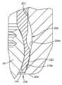
도1은 본 발명에 따른 도4의 선 1-1을 따라 취해진 로킹 해제 상태에서의 앵커 조립체의 제1의 양호한 실시예의 단면도이다.
도2는 로킹 상태에서의 도1의 앵커 조립체의 단면도이다.
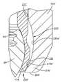
도3은 본 발명에 따른 로킹 해제 상태에서의 앵커 조립체의 제2의 양호한 실시예의 단면도이다.
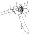
도4는 도1의 앵커 조립체의 평면 사시도이다.
도4a는 척추뼈 내에 매식되고 제2 뼈 고정 요소에 부착된 도1의 앵커 조립체의 평면 사시도이다.
도5는 도1의 앵커 조립체의 콜릿 요소의 평면 사시도이다.
도5a는 도5의 선 5A-5A를 따라 취해진 도5의 콜릿 요소의 단면도이다.
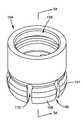
도6은 도1의 앵커 조립체를 위한 로킹 캡 및 고정 나사 조립체의 측면도이다.
도7은 도6의 조립체의 고정 나사 요소의 평면 사시도이다.
도8은 도6의 조립체의 로킹 캡 요소의 평면 사시도이다.
도9는 도7의 선 9-9를 따라 취해진 도7의 고정 나사 요소의 단면도이다.
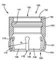
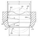
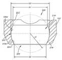
도10a는 도1의 앵커 조립체의 본체 부분의 확대 단면도이다.
도10b는 도2의 타원(10B)의 내부로부터 취해진 도1의 앵커 조립체의 본체 부분, 콜릿 요소 그리고 나사의 헤드의 확대 단면도이다.
도10c는 도3의 앵커 조립체의 본체 부분의 확대 단면도이다.
도10d는 콜릿 요소 그리고 나사의 헤드가 본체 부분에 대해 약간 하향으로 이동된 도3의 타원(10D)의 내부로부터 취해진 도3의 앵커 조립체의 본체 부분, 콜릿 요소 그리고 나사의 헤드의 확대 단면도이다.The above summary and also the following detailed description of the preferred embodiment of the system described herein will be better understood when read in conjunction with the accompanying drawings. Preferred embodiments of the anchor assembly are shown in the drawings for purposes of illustration. However, the present disclosure is not limited to the specific arrangements, structures, features, embodiments, means and methods shown and described, and the arrangements, structures, features, embodiments, means and methods shown and described may be used alone or in other arrangements, structures, It should be understood that it may be used in combination with features, embodiments, means and methods.
1 is a cross-sectional view of a first preferred embodiment of an anchor assembly in an unlocked state taken along line 1-1 of FIG. 4 in accordance with the present invention.
2 is a cross-sectional view of the anchor assembly of FIG. 1 in a locked state.
3 is a cross-sectional view of a second preferred embodiment of the anchor assembly in the unlocked state according to the present invention.
4 is a top perspective view of the anchor assembly of FIG.
4A is a top perspective view of the anchor assembly of FIG. 1 embedded in the vertebrae and attached to a second bone fixation element.
5 is a top perspective view of the collet element of the anchor assembly of FIG.
5A is a cross sectional view of the collet element of FIG. 5 taken along
6 is a side view of the locking cap and set screw assembly for the anchor assembly of FIG.
7 is a top perspective view of a set screw element of the assembly of FIG.
8 is a top perspective view of the locking cap element of the assembly of FIG.
9 is a cross sectional view of the set screw element of FIG. 7 taken along line 9-9 of FIG.
10A is an enlarged cross-sectional view of a body portion of the anchor assembly of FIG.
10B is an enlarged cross-sectional view of the body portion, collet element, and head of the screw of the anchor assembly of FIG. 1 taken from the interior of ellipse 10B of FIG.
FIG. 10C is an enlarged cross-sectional view of the body portion of the anchor assembly of FIG.
10D is an enlarged cross-sectional view of the body portion, collet element and head of the anchor assembly of FIG. 3 taken from the interior of the ellipse 10D of FIG. 3 with the collet element and the head of the screw moved slightly downward relative to the body portion.
일부 용어는 단지 편의상 다음의 설명에서 사용되고, 제한적인 의미를 갖지 않는다. 단어 "우측(right)", "좌측(left)", "하부(lower)", "상부(upper)", "상부(top)" "저부(bottom)"는 인용이 수행되는 도면에서 방향을 표시한다. 단어 "내향으로(inwardly)" 또는 "말단 방향으로(distally)" 및 "외향으로(outwardly)" 또는 "근접 방향으로(proximally)"는 각각 앵커 조립체, 설명된 기구 및 그 표시된 부분의 기하학적 중심을 향한 또는 기하학적 중심으로부터 멀어지는 방향을 말한다. 단어 "전방(anterior)", "후방(posterior)", "위(superior)", "아래(inferior)", "내측(medial)" 및 "측방(lateral)" 그리고 관련된 단어 및/또는 어구는 인용이 수행되는 인체 부분 내의 양호한 위치 및 배향을 표시하고, 제한적인 의미를 갖지 않는다. 용어는 위에서-나열된 단어, 그 파생어 그리고 유사한 의미의 단어를 포함한다.Some terms are used in the following description for convenience only and do not have a limiting meaning. The words "right", "left", "lower", "upper", "top" and "bottom" refer to directions in the drawings in which citations are made. Display. The words "inwardly" or "distally" and "outwardly" or "proximally" refer to the anchor assembly, the instrument described and the geometric center of the indicated part, respectively. Refers to the direction towards or away from the geometric center. The words "anterior", "posterior", "superior", "inferior", "medial" and "lateral" and related words and / or phrases It indicates a good position and orientation in the body part where the citation is made and does not have a limiting meaning. The term includes above-listed words, derivatives thereof, and words of similar meaning.
이제부터, 본 발명의 일부 예시 실시예가 도면을 참조하여 설명될 것이다. 일반적으로, 이러한 실시예는 비-제한 예로서의 앵커 조립체 그리고 관련된 기구의 양호한 실시예에 관한 것이다. 척추 고정에서 사용되는 이러한 앵커 조립체는 바람직하게는 앵커 조립체의 일부로서 일체로 및 단일로 형성될 수 있고 척추 만곡을 교정 또는 안정화시키는 뼈 고정 시스템에서 제2 뼈 고정 요소에 앵커 조립체를 연결하기 위해 그리고 척추뼈의 융합을 촉진시키기 위해 제2 뼈 고정 요소의 로드-수용 채널 내로 삽입될 수 있는 전형적으로 척추 로드 부분의 형태로 된 긴 부재를 포함한다.Some exemplary embodiments of the present invention will now be described with reference to the drawings. In general, such embodiments relate to preferred embodiments of non-limiting examples of anchor assemblies and associated instruments. Such anchor assemblies for use in spinal fixation can preferably be formed integrally and singly as part of the anchor assembly and for connecting the anchor assembly to the second bone fixation element in a bone fixation system that corrects or stabilizes spinal curvature and It comprises an elongate member, typically in the form of a spinal rod portion, which can be inserted into the rod-receiving channel of the second bone fixation element to facilitate fusion of the vertebrae.
도1-도4a를 참조하면, 앵커 조립체(100, 100')의 제1 및 제2의 양호한 실시예는 (뼈 나사로서 도시된) 뼈 앵커(105), 콜릿(104), 로드 부분(101)을 갖는 본체 부분(102, 102') 그리고 도1-도2 및 도4의 제1의 양호한 실시예에서 외부 나사산 고정 나사(106)를 포함하는 로킹 캡(103)을 포함한다. 앵커 조립체(100, 100')는 바람직하게는 본체 부분(102, 102')으로의 뼈 앵커(105)의 현장 조립을 가능케 한다. 구체적으로, 앵커 조립체(100, 100')는 사용 시에 뼈 앵커(105)가 본체 부분(102, 102') 내에 수용되기 전에 환자의 척추뼈(200)에 고정될 수 있도록 구성된다. 앵커 조립체(100, 100')는 바람직하게는 본체 부분(102, 102') 및 콜릿(104)이 뼈 앵커(105)에 사전 조립되지 않은 상태에서 수술의가 뼈 앵커(105)를 매식할 수 있게 한다. 수술의가 본체 부분(102, 102') 없이 뼈 앵커(105)를 매식할 수 있게 함으로써, 앵커 조립체(100, 100')는 고정 지점 주위에서의 가시성 및 접근성을 최대화한다. 일단 뼈 앵커(105)가 환자의 척추뼈(200)에 고정되면, 로드 부분(101)이 제2 지점에 고정되는 제2 뼈 고정 요소(10)(도4a) 내로 삽입될 수 있고, 본체 부분(102, 102') 및 콜릿(104)이 뼈 앵커(105)에 "팝 방식으로 결합"될 수 있다.Referring to FIGS. 1-4A, the first and second preferred embodiments of
대체예에서, 본체 부분(102, 102') 및 콜릿(104)이 뼈 앵커(105) 상으로 팝 방식으로 결합될 수 있고, 그 다음에 일체형 로드 부분(101)이 제2 지점에서의 제2 뼈 고정 요소(10) 내로 삽입될 수 있다. 따라서, 양호한 앵커 조립체(100, 100')에서, 뼈 앵커(105)는 본체 부분(102, 102')의 하부 또는 저부 단부(205, 205')를 통해 본체 부분(102, 102') 내로 진입된다. 더욱이, 본체 부분(102, 102') 내로의 로드 부분(101)의 일체화 그리고 바람직하게는 단일화 형성은 이러한 일체화가 수술의가 별도의 로드를 매식할 필요 없이 여러 개의 뼈 고정 요소를 함께 융합하게 하기 때문에 더 간단하고 더 효율적인 시술을 용이하게 한다. 대체예에서, 앵커 조립체(100, 100')[즉, 본체 부분(102, 102'), 콜릿(104) 및 뼈 앵커(105)]는 여기에서 설명된 구성 요소와 동일 또는 유사한 구성 요소를 사용하여 사전-조립된 상태로 제공될 수 있다. 또한, 콜릿(104) 및 본체 부분(102, 102')의 조립은 아래에서 더 상세하게 설명되는 것과 같이 본체 부분(102, 102')에 대해 적재/적재 해제 위치에 콜릿(104)을 배열하여 위치시키고 뼈 앵커(105)로부터 조립체를 제거함으로써 현장에서 뼈 앵커(105)로부터 팝 방식으로 결합 해제될 수 있다.In the alternative, the
제1의 양호한 실시예의 앵커 조립체(100)는 일반적으로 척추에서(예컨대, 요추, 흉부 또는 경부 영역에서) 사용될 수 있는 것으로서 설명되었지만, 당업자라면 앵커 조립체(100)가 예컨대 관절, 장골(long bone), 늑골(rib) 또는 손, 얼굴, 발, 발가락, 말단부, 두개골(cranium), 하악골(mandible) 등 내의 뼈 등의 신체의 다른 부분의 고정을 위해 사용될 수 있다는 것을 이해할 것이다.Although the
아래에서 더 상세하게 설명되는 것과 같이 그리고 도4a에 도시된 것과 같이, 여러 개의 앵커 조립체(100) 그리고 로드-수용 채널을 갖는 제2 뼈 고정 요소(10)가 여러 개의 척추뼈(200)를 고정 및 상호 연결하는 데 사용될 수 있다. 척추 로드(101)는 고체 로드, 비-고체 로드 또는 중공 로드, 가요성 또는 동적 로드(dynamic rod) 등으로 구성되거나 이것들을 포함하지만 이것들에 제한되지 않는다는 것이 이해되어야 한다. 제1 및 제2의 양호한 실시예의 앵커 조립체(100, 100')는 임의의 특정 형태의 척추 로드(101)에 용도 면에서 제한되지 않고, 본체 부분(102, 102')으로부터 연장되는 임의의 형상 및 구성의 임의의 긴 요소를 포함할 수 있다.As described in more detail below and as shown in FIG. 4A,
도1-도2 및 도5-도5a를 참조하면, 제1의 양호한 실시예의 뼈 앵커(105)는 뼈 나사 또는 경부 나사(105)의 형태로 되어 있다. 대체예에서, 뼈 앵커(105)는 예컨대 후크(hook), 핀(pin), 블레이드(blade), 네일(nail), 택(tack), 스테이크(stake) 또는 클램프(clamp), 매식체 등의 다른 체결구일 수 있다.1-2 and 5-5, the
뼈 나사(105)는 바람직하게는 확대 만곡 헤드 부분(24) 그리고 환자의 척추뼈(200)와 결합되는 외부 나사산 샤프트 부분(26)을 포함한다. 예컨대 나사산 피치, 샤프트 직경, 샤프트 형상 등을 포함한 샤프트(26)의 특정 특징은 변동될 수 있고, 뼈 나사(105)는 임의의 특정 특징 또는 형태의 샤프트(26)에 제한되지 않는다는 것이 당업자에게 명백할 것이다. 뼈 나사(105)는 캐뉼러형(cannulated)일 수 있거나 그렇지 않을 수 있다. 뼈 나사(105)는 뼈 나사(105)에 대한 본체 부분(102)의 다축 성질을 수용하는 헤드 부분(24)과 샤프트 부분(26) 사이의 감소 직경 네크 부분(28)을 또한 포함한다. 뼈 나사(105)는 개구가 주입 중에 나사(105)의 외부로 재료를 압박하는 것, 나사(105)에 인접한 재료를 인출하기 위해 나사(105)의 측면으로부터 중심 중공 채널 내로 유체를 흡인하는 것 또는 기구 또는 추가의 매식체를 통과하는 것을 포함하지만 이것들에 제한되지 않는 많은 잠재적 용도를 위해 중심 중공 채널로부터 외향으로 연장되도록 더욱 (도시되지 않은) 캐뉼러형(cannulated) 또는 피네스트레이트형(fenestrated)일 수 있다.
도1을 참조하면, 확대 만곡 헤드 부분(24)은 바람직하게는 콜릿(104)에 대한 헤드 부분(24)의 피벗 또는 다축 운동을 용이하게 하기 위해 만곡 또는 반-구형 형상을 갖는다. 헤드 부분(24)은 바람직하게는 환자의 척추뼈(200)와 결합 상태로 뼈 나사(105)를 회전시키는 (도시되지 않은) 나사 드라이버 등의 구동 공구 상에 형성되는 대응 팁을 수용하는 구동 표면(30)을 또한 포함한다. 구동 표면(30)은 외부 육각형, 별형 구동 패턴(star drive pattern), 필립스 헤드 패턴(Phillips head pattern), 나사 드라이버를 위한 슬롯, 대응 나사산 포스트를 위한 나사산 등을 포함하지만 이것들에 제한되지 않는 현재 또는 현재 이후에 알려질 임의의 형태를 가질 수 있다. 바람직하게는, 도시된 것과 같이, 구동 표면(30)은 제1 공구 인터페이스 또는 내부 리세스(32)를 포함하지만, 이렇게 제한되지 않고 (도시되지 않은) 암형 드라이버와 결합되는 외부 구동 특징부를 포함할 수 있다. 구동 표면(30) 또는 제1 공구 인터페이스(32)의 특정 형상은 대응 구동 공구와 협력하도록 선택될 수 있다.Referring to FIG. 1, the enlarged
그 전체 내용이 여기에 참조로 합체되어 있는 2008년 7월 21일자로 출원된 발명의 명칭이 "다축 뼈 고정 요소"인 국제 출원 제PCT/US2008/070670호에 개시된 것과 같이, 헤드 부분(24)은 제2 공구 인터페이스 또는 슬리브 인터페이스(40)를 또한 포함할 수 있다. 제2 공구 인터페이스(40)는 구동 기구 등의 기구와 상호 작용하도록 (도시된 것과 같은) 나사산 또는 다른 특징부를 포함할 수 있다.
도5-도5a를 참조하면, 콜릿(104)은 바람직하게는 뼈 앵커(105)의 헤드 부분(24)의 적어도 일부와 접촉되도록 된 크기 및 구성으로 되어 있는 하부 단부 부분(154)을 포함한다. 콜릿(104)의 하부 단부 부분(154)은 바람직하게는 당업자에 의해 일반적으로 이해되는 것과 같이 뼈 앵커(105)가 로킹 해제 위치에 있을 때에 콜릿(104) 그에 따라 본체 부분(102)에 대해 소정 범위의 각도를 통해 다축 피벗 또는 운동될 수 있도록 뼈 앵커(105)의 헤드 부분(24)을 수용 및 고정하는 내부 공동(165)을 포함한다. 콜릿(104) 내에 형성된 공동(165)은 바람직하게는 뼈 앵커(105)가 콜릿(104) 그에 따라 본체 부분(102)에 대해 다축 회전될 수 있도록 뼈 앵커(105)의 만곡 또는 반-구형 헤드 부분(24)을 수용하는 만곡 또는 반-구형 형상을 갖는다. 또한, 콜릿(104)의 외부 표면의 적어도 일부가 아래에서 더 상세하게 설명되는 것과 같이 본체 부분(102)의 내부 표면(211)(도2) 바람직하게는 하부 모서리 부분(218) 또는 내부 표면(211)과 접촉되는 곡률 반경(r5)을 갖는 만곡 또는 절두-구형 볼록 표면(151)을 포함한다.5-5A,
콜릿(104)은 바람직하게는 콜릿(104)의 적어도 일부가 (ⅰ) 뼈 앵커(105)의 헤드 부분(24)이 하부 단부 부분(154)을 통해 그리고 콜릿(104)의 공동(165) 내로 삽입될 수 있도록 반경 방향으로 팽창 가능하도록, 그리고 (ⅱ) 반경 방향 힘이 그에 인가될 때에 뼈 앵커(105)의 헤드 부분(24)에 대해 압축 또는 크러시-로킹(crush-lock)되도록 반경 방향으로 압축 가능하도록 그 하부 단부 부분(154)으로부터 연장되는 [복수개의 슬롯(170)으로서 도시된] 1개 이상의 슬롯(170)을 포함한다. 양호한 실시예에서, 슬롯(170)은 복수개의 가요성 암(108)을 형성한다. 바람직하게는, 각각의 가요성 암(108)은 루트 단부(173) 및 말단 단부(174)를 포함한다. 가요성 암(108)의 외부 표면은 바람직하게는 콜릿(104)의 만곡 또는 절두-구형 볼록 표면(151)의 적어도 일부를 형성한다.The
콜릿(104)은 예컨대 (도시되지 않은) 나사 드라이버 등의 구동 공구가 콜릿(104)을 통해 그리고 뼈 앵커(105)와 결합 상태로 삽입될 수 있고 그에 의해 뼈 앵커(105)가 환자의 척추뼈(200)와 결합 상태로 회전될 수 있도록 상부 단부(152)에서의 상부 개구(160)로부터 하부 단부(154)까지 연장되는 보어(156)를 또한 포함한다.The
콜릿(104)은 적재/적재 해제/로킹 해제 위치(도1)와 로킹 위치(도2) 사이에서 본체 부분(102) 내에 형성된 축 방향 보어(206) 내에서 이동되게 된다. 그러나, 콜릿(104)은 바람직하게는 상부 개구(203)를 통해 본체 부분(102) 내로 삽입될 수 있지만 하부 개구(205)를 통해 배출되는 것이 방지되도록 구성된다. 일단 콜릿(104)이 본체 부분(102) 내로 위치되면, 콜릿(104)은 바람직하게는 콜릿(104)이 일반적으로 본체(102) 내에 형성된 상부 개구(203)를 후방으로 통과하는 것 또는 본체(102) 내에 형성된 하부 개구(205)를 통과하는 것 중 어느 한쪽이 방지되도록 본체 부분(102) 내에 보유 가능하다.The
도5-도5a를 참조하면, 콜릿(104)은 콜릿(104)의 상부 단부(152)에 인접한 콜릿 본체(193)의 내부 표면(161) 상에 배치되는 내향 돌출 레지(inwardly projecting ledge)(184)를 포함한다. 레지(184)는 콜릿(104)에 힘을 인가하여 본체 부분(102)에 대해 콜릿(104)을 이동시키기 위해 (도시되지 않은) 공구에 의해 결합될 수 있다. 예컨대, 콜릿(104), 본체 부분(102) 및 뼈 앵커(105)가 로킹 위치에 있을 때에, 본체 부분(102)이 로킹 위치로부터 적재 위치 내로 콜릿(104)을 이동시키기 위해 콜릿(104)에 대해 뼈 앵커(105)를 향해 하향으로 압박될 수 있다. 콜릿(104)이 적재 위치에 있을 때에, 가요성 암(108)이 헤드(24)가 공동(165)의 외부로 이동되게 하기 위해 확대 직경 부분(220) 내에서 외향으로 굽혀질 수 있다. 따라서, 레지(184)는 콜릿(104) 및 본체 부분(102)이 헤드(24)에 로킹된 후에 뼈 앵커(105)로부터 콜릿(104) 및 본체 부분(102)을 분해하는 데 이용될 수 있다.5-5A, the
도1, 도2, 도10a 및 도10b를 참조하면, 본체 부분(102)은 일반적으로 길이 방향 축(201), 상부 개구(203)를 갖는 상부 단부(202), 하부 개구(205)를 갖는 하부 단부(204) 그리고 본체 부분(102)의 길이 방향 축(201)과 실질적으로 동축인 축 방향 보어(206)를 포함하는 원통형 튜브형 본체 부분으로서 설명될 수 있다. 축 방향 보어(206)는 상부 개구(203)로부터 하부 개구(205)까지 연장된다. 축 방향 보어(206)는 바람직하게는 상부 단부(202)에 근접한 제1 직경 부분(D1)을 갖는다. 축 방향 보어(206)의 내부 표면(211)은 바람직하게는 로킹 캡(103)과 결합되는 상부 단부(202) 내의 복수개의 나사산(212)을 포함한다. 대체예에서, 본체 부분(102) 특히 축 방향 보어(206)는 외부 나사산, 캠-로크(cam-lock), 쿼터 로크(quarter lock), 클램프, 러그(lug), 베이어너트(bayonet) 등을 포함하지만 이것들에 제한되지 않는 로킹 캡(103)과 결합되는 거의 임의의 장착 수용 구조물을 가질 수 있다.1, 2, 10A and 10B, the
도1-도3 및 도10a-도10d를 참조하면, 제1 및 제2의 양호한 실시예의 축 방향 보어(206, 206')의 내부 표면(211, 211')은 하부 챔버(219, 219')를 형성하는 그 하부 단부(204, 204')에 근접한 하부 단부 부분(218, 218')을 또한 포함한다. 하부 챔버(219, 219')는 바람직하게는 축 방향 보어(206, 206')의 최소 직경 부분을 갖는 하부 개구(205, 205')에서의 제2 직경 부분(D2, D2')을 갖는다. 제2 직경 부분(D2, D2')은 바람직하게는 콜릿(104)이 축 방향 보어(206, 206') 내로 상부 단부(202, 202')를 통해 삽입될 수 있지만 하부 단부(204, 204')에서의 하부 개구(205, 205')를 통해 삽입되거나 하부 단부(204, 204')에서의 하부 개구(205, 205')로부터 낙하되는 것을 방지하도록 축 방향 보어(206, 206')의 제1 직경 부분(D1, D1')보다 작다. 제2 직경 부분(D2, D2')은 바람직하게는 뼈 앵커(105)의 확대 헤드 부분(24)이 콜릿(104)의 내부 공동(165) 내에 수용되도록 본체 부분(102, 102')의 하부 개구(205, 205')를 통과할 수 있도록 된 크기 및 구성으로 되어 있다.1 through 3 and 10A-D, the
제1 및 제2의 양호한 실시예의 하부 챔버(219, 219')는 본체 부분(102, 102')의 하부 단부(204, 204')에 인접한 제1 구형 표면(218a, 218a')에 의해 형성된다. 제1 구형 표면(218a, 218a')은 바람직하게는 콜릿(104)의 외부 만곡 또는 구형 볼록 표면(151)을 수용하는 만곡 또는 구형 오목 표면으로서 형성된다. 제1 구형 표면(218a, 218a')은 콜릿(104)이 로킹 위치에서 하부 단부(204, 204')에 근접하게 위치될 때에 선 접촉이 외부 만곡 및 제1 구형 표면(151, 218a, 218a')들 사이에서 형성되도록 바람직하게는 본체 부분(102, 102')의 길이 방향 축(201, 201') 상에 중심이 위치되고 콜릿(104)의 구형 볼록 표면(151)의 곡률 반경(r5)과 상이한 (도10a에 도시된) 제2 곡률 반경(r2, r2')을 갖는다.The
축 방향 보어(206, 206')의 내부 표면(211, 211')은 바람직하게는 하부 챔버(219, 219')와 상부 단부(202, 202') 사이에서 본체 부분(102, 102')의 하부 단부(204, 204')를 향해 위치되는 확대 부분(220, 220')을 포함한다. 확대 부분 또는 제2 챔버(220, 220')는 바람직하게는 만곡 바람직하게는 절두-구형의 반경 방향 외향 리세스형 부분을 포함하는 제3 직경부(D3, D3')를 형성한다. 축 방향 보어(206, 206')의 확대 부분(220, 220')에서, 제3 직경부(D3, D3')는 축 방향 보어(206, 206')의 제1 직경부(D1, D1')보다 크다. 또한, 제3 직경부(D3, D3')는 제2 직경부(D2, D2')보다 크다.The
확대 부분(220, 220')은 바람직하게는 헤드(24)가 콜릿(104) 내로 적재될 때에 가요성 암(108)의 팽창을 수용한다. 확대 부분(220, 220')은 바람직하게는 만곡 또는 절두-구형 오목 내부 표면(220a, 220a')의 형태로 되어 있다. 도10a 및 도10b를 참조하면, 제1의 양호한 실시예에서, 내부 표면(220a)은 축 방향 보어(206) 내의 최대 직경부에서 제3 직경부(D3)를 형성하는 제3 곡률 반경(r3)에 의해 형성된다. 제3 곡률 반경(r3)은 제2 구형 표면(220a)의 구형 성질을 형성한다. 제3 곡률 반경(r3)은 바람직하게는 제2 곡률 반경(r2)과 상이하고, 또한 콜릿(104)의 구형 볼록 표면(151)의 곡률 반경(r5)과 상이하지만 반드시 그럴 필요는 없다. 확대 부분(220)은 콜릿(104)이 확대 부분(220)의 만곡 또는 절두-구형 오목 내부 표면 내에 위치될 때에 콜릿(104)의 가요성 암(108)이 본체 부분(102)의 축 방향 보어(206) 내에 충분한 크기만큼 반경 방향으로 팽창되게 하고 그에 의해 뼈 앵커(105)의 헤드 부분(24)이 콜릿(104) 내에 형성된 공동(165) 내로 삽입될 수 있도록 된 크기 및 구성으로 되어 있다. 더 바람직하게는 그러나 반드시 그럴 필요는 없지만, 확대 부분(220)은 헤드(24)가 콜릿(104) 내로 적재될 때에 콜릿(104)의 외부 만곡 또는 절두-구형 볼록 표면(151)이 본체 부분(102)의 확대 부분(220)과 접촉되지 않도록 된 크기 및 구성으로 되어 있다. 즉, 본체 부분(102) 내에 형성된 확대 부분(220)은 바람직하게는 가요성 암(108)이 뼈 앵커(105)의 헤드 부분(24)을 수용할 정도로 충분히 반경 방향으로 팽창될 수 있도록 된 크기 및 구성으로 되어 있다. 확대 부분(220)은 제3 곡률 반경(r3)에 의해 형성된 양호한 만곡 또는 구형 표면을 포함하는 구성에 제한되지 않고, 적재 위치에서의 콜릿(104)의 팽창이 헤드(24)를 수용하게 하는 거의 임의의 형상의 표면을 갖도록 구성될 수 있다. 예컨대, 확대 부분(220)은 내부 표면(211) 상의 직사각형 슬롯 또는 홈 또는 제1 및 제2 직경부(D1, D2)보다 큰 제3 직경부(D3)를 생성하는 원통형 챔버에 의해 형성될 수 있다.The
도10a-도10b를 참조하면, 제1의 양호한 실시예에서, 제1 구형 표면(218a)의 제2 곡률 반경(r2)은 바람직하게는 콜릿(104)이 하부 단부 부분(218)에 인접하게 위치될 때에 대체로 선 접촉이 제1 구형 표면(218a)과 외부 볼록 표면(151) 사이에서 생성되도록(도10b) 콜릿(104)의 외부 만곡 또는 구형 볼록 표면(151)의 외부 곡률 반경(r5)과 상이하다. 곡률 반경(r2, r5)이 동일하지 않기 때문에, 만곡 표면들이 대체로 큰 표면적을 따라 접촉되지 않고, 오히려 대체로 선 또는 제한된 두께 또는 폭의 선을 따라 접촉되고, 그에 의해 대체로 선 접촉을 형성한다. 즉, 제1 구형 표면(218a)과 콜릿(104) 사이에 비-정합 곡률 반경(r2, r5)을 제공함으로써, 선 접촉이 대체로 본체 부분(102)의 제1 구형 표면(218a)과 콜릿(104)의 외부 만곡 또는 구형 볼록 표면(151) 사이에서 발생된다. 본체 부분(102)과 콜릿(104) 사이에서의 대체적인 선 접촉은 콜릿(104)의 하부 단부(154)가 헤드(24)의 최대 직경부 아래에서 가압되고 그에 의해 효과적으로 콜릿(104)에 뼈 앵커(105)를 로킹하고 로킹 위치에 콜릿(104)을 위치시키도록 헤드(24)의 최대 직경부 아래에서 헤드(24)의 하부 단부 내로 가요성 암(108)의 하부 단부를 효과적으로 고정한다.10A-10B, in a first preferred embodiment, the second radius of curvature r2 of the first
도10c-도10d를 참조하면, 제2의 양호한 실시예에서, 제2 및 제3 직경(D2', D3')은 본체 부분(102')의 축 방향 보어(206') 내에 형성되는 단일 내부 곡률 반경(r4')에 의해 형성될 수 있다. 단일 내부 곡률 반경(r4')은 바람직하게는 하부 단부(204')가 아니라 상부 단부(202')로부터 축 방향 보어(206') 내로의 콜릿(104)의 삽입을 허용하고, 콜릿(104')이 하부 단부(204')를 통해 배출되는 것을 방지하고, 콜릿(104)의 팽창이 헤드(24)를 수용하게 하고, 콜릿(104)이 하부 단부 부분(218')과 대면 결합 상태에 있을 때에 콜릿의 외부 만곡 또는 구형 볼록 표면(151)과 제1 구형 표면(218a') 사이에서의 대체적인 선 접촉을 허용한다. 이러한 구성에서, 제2 직경 부분(D2')은 제3 직경 부분(D3')보다 작은 제1 직경 부분(D1')보다 작다.10C-10D, in a second preferred embodiment, the second and third diameters D2 ′, D3 ′ are formed in the
도1-도4 및 도6-도8을 참조하면, 로킹 캡은 바람직하게는 2개-편 로킹 캡(103) 또는 단일편 로킹 캡(213) 중 어느 한쪽일 수 있다. 양쪽 모두의 양호한 실시예에서, 로킹 캡(103, 213)은 일반적으로 본체 부분(102, 102')의 내부 표면(211, 211') 상에 형성된 나사산(212, 212')과 나사산 결합되는 외부 나사산(303)을 갖는 원통형 튜브형 로킹 캡(103, 213)으로서 설명될 수 있다. 로킹 캡(103, 213)은 또한 본체 부분(102, 102')으로부터 분리 가능한 것 또는 분리 불가능한 것 중 어느 한쪽일 수 있다. 로킹 캡(103, 213)은 외부 나사산 캡, 내부 나사산 캡, 쿼터-턴(quarter turn) 또는 부분-턴(partial turn) 로킹 캡, 캠-로크 베이어너트 및 러그, 2개-편 고정 나사 등을 포함하지만 이것들에 제한되지 않는 이러한 목적을 위해 현재에 알려져 있거나 현재 이후에 개발될 임의의 로킹 캡일 수 있다.Referring to Figures 1-4 and 6-8, the locking cap may preferably be either a two-
도1-도2, 도4 및 도6-도8에 도시된 것과 같이, 2개-편 로킹 캡(103)은 고정 나사 요소(106)를 포함한다. 로킹 캡(103)은 보어(307) 그리고 고정 나사(106)의 외부 나사산(701)(도7)과 나사산 결합되도록 로킹 캡(103)의 내부 상에 배치되는 내부 나사(309)(도8)를 추가로 포함한다. 로킹 캡(103) 및 고정 나사(106)는 바람직하게는 본체 부분(102) 상으로 로킹 캡(103) 및 고정 나사(106)를 고정(예컨대, 나사산 결합)하는 대응 구동 공구와 결합되는 구동 표면(311, 313)(도4 참조)을 포함한다. 구동 표면(311, 313)은 외부 육각형, 별형 구동 패턴, 필립스 헤드 패턴, 나사 드라이버를 위한 슬롯, 대응 나사산 포스트를 위한 나사산 등을 포함하지만 이것들에 제한되지 않는 이러한 목적을 위해 현재 또는 현재 이후에 개발될 임의의 형태를 취할 수 있다. 구동 표면(311, 313)은 바람직하게는 내부 리세스를 각각 포함한다. 내부 리세스의 특정 형상은 대응 구동 공구와 협력하도록 선택될 수 있다. 구동 표면(311, 313)은 또한 위에서 설명된 것과 같은 제1 및 제2 공구 인터페이스(32, 40)를 포함하도록 구성될 수 있다.As shown in FIGS. 1-2, 4 and 6-8, the two-
대체예에서, 2개-편 로킹 캡(103)은 도1-도2에 가장 잘 도시된 것과 같은 본체 부분(102)의 상부 단부(202)의 내부 표면(211) 상의 나사산의 나사산 피치와 상이한 나사산 피치를 가질 수 있다. 구체적으로, 도6 및 도8에 가장 잘 도시된 것과 같은 로킹 캡(103)의 외부 나사산(303)의 적어도 일부의 나사산 피치는 로킹 캡(103)이 소정 거리에서 본체 부분(102)과 결속되지만 앵커 조립체(100)가 예컨대 상이한 크기에 대해 교환될 것이 요구되면 본체 부분(102)으로부터 제거 가능하도록 내부 표면(211) 상의 나사산의 적어도 일부의 나사산 피치와 상이하다. 이러한 구성에서, 로킹 캡(103)이 본체 부분(102) 내에서 하향으로 진행됨에 따라 결합 나사산들 사이에서 경험되는 간섭의 크기는 함께 결합되는 나사산의 크기에 대해 기하급수적으로 증가된다. 로킹 캡(103)의 외부 나사산(303)과 본체 부분(102) 내에 형성된 나사산(212) 사이의 부정합은 이러한 특징이 부정합 나사산의 결속 및 마찰 끼워맞춤으로 인해 조립체의 후퇴 저항(back-out resistance)을 향상시키기 때문에 유리하다. 나사산(303, 212)의 단지 일부가 나사산 피치가 본체 부분(102) 내에 형성된 나사산(212)에 대해 약 1.15 ㎜이고 로킹 캡(103) 상에 형성된 나사산(303)에 대해 약 1.0 ㎜일 수 있는 경우에 부정합될 수 있다. 나사산 피치, 나사산 프로파일, 나사산 피치들 사이의 차이 그리고 부정합된 나사산의 부분은 요구된 간섭의 크기에 따라 변동될 수 있다.In an alternative, the two-
단일편 로킹 캡(213)은 바람직하게는 도3에 가장 잘 도시된 것과 같이 고정 나사 요소를 포함하지 않는다. 마찬가지로, 단일편 로킹 캡(213)은 본체 부분(102) 상으로 로킹 캡(213)을 고정(나사산 결합)하는 대응 구동 공구와 결합되는 구동 표면(311, 313)을 포함할 수 있다.The one-
대체예에서, 단일편 로킹 캡(213)은 도1-도2에 가장 잘 도시된 것과 같은 본체 부분(102)의 상부 단부(202)의 내부 표면(211) 상의 나사산의 나사산 피치가 로킹 캡(213)의 외부 나사산(303)의 나사산 피치(도3)와 상이한 경우에 또한 제공될 수 있다. 이와 같이, 로킹 캡(103)의 외부 나사산과 본체 부분(102)의 내부 나사산 사이의 부정합의 동일한 원리가 2개-편 로킹 캡(103)에 대해 위에서 논의된 것과 같이 고정 나사 없는 단일편 로킹 캡 요소(예컨대, 도3)에 대해 이용될 수 있다.Alternatively, the single
로킹 캡(103, 213)은 사전-조립될 수 있고 일반적으로 본체 부분(102)으로부터 분리 불가능할 수 있고, 그에 의해 수술 중에 본체 부분(102)에 로킹 캡(103, 213)을 조립할 필요성을 제거하고, 수술 단계를 감소시키고, 로킹 캡(103, 213)과 본체 부분(102) 사이의 교차-나사 결합의 가능성을 방지하고, 수술 지점 내에서 또는 수술 지점 근처에서 로킹 캡(103, 213)을 떨어뜨리거나 잃어버릴 위험성을 제거한다. 로킹 캡(103, 213)이 본체 부분(102)으로부터 분리 불가능하게 하는 것은 본체 부분(102)의 축 방향 보어(206)의 원주부 주위에 돌출 레지를 추가하는 것 또는 본체 부분(102)의 나사산(212) 또는 본체(102)의 내부 벽 상에 배치되는 제2 보유 요소 중 어느 한쪽과 결합될 수 있는 로킹 캡(103, 213)의 기부에서의 보유 요소를 포함하는 것을 포함하지만 이것들에 제한되지 않는 많은 방식으로 성취될 수 있다. 대체예에서 또는 추가예에서, 로킹 캡(103, 213)의 나사산(303)과 결합 가능한 본체(102)의 나사산(212)은 로킹 캡(103, 213)이 본체 부분(102)으로부터 분리되는 것을 방지하는 과정에서 손상될 수 있다. 로킹 캡(103, 213)이 본체 부분(102)으로부터 분리 불가능하게 하는 것은 수술의가 일반적으로 본체 부분(102)의 보어(206)의 상부 개구(203)를 통해 뼈 앵커(105)를 조작하거나 척추뼈(200)로의 뼈 앵커 및 앵커 조립체의 부착 후에 척추 로드를 매식할 필요가 없도록 일체형 로드 부분(101) 그리고 뼈 앵커(105)의 저부-적재 구성에 의해 가능해진다.The locking caps 103, 213 may be pre-assembled and generally inseparable from the
로킹 캡(103)은 예컨대 상이한 스타일의 앵커 조립체(100) 예컨대 더 길거나 더 짧은 본체 부분(102) 또는 로드 부분(101)을 갖는 것 등이 바람직할 때에 수술의가 환자로부터 앵커 조립체를 제거하기로 결정한 경우에 수술의가 콜릿(104) 상의 (도시되지 않은) 제거 특징부에 접근하여 뼈 앵커(105)의 헤드(24)로부터 콜릿(104)을 결합 해제하게 하고 뼈 앵커(105)로부터 앵커 조립체(100)를 제거하게 하도록 본체 부분(102)으로부터 분리 가능할 수 있다.The locking
도3 및 도9를 참조하면, 본체 부분(102) 상에 형성된 나사산(212)(도2)과 결합되는 로킹 캡(103, 213) 상에 형성된 외부 나사산(303)은 본체 부분(102)의 길이 방향 축(201)에 직각인 선(L9)에 대해 각도(θ)를 형성하는 경사형 적재 플랭크(inclined load flank)(703)를 포함할 수 있다. 적재 플랭크(703)는 나사산(303)의 상부 표면(705) 그리고 나사산(303)의 저부 표면(707)이 수렴되도록 수렴형일 수 있다. 각도(θ)는 약 5˚일 수 있지만, 일반적으로 당업자에 의해 대체로 이해되는 것과 같이, 나사산은 음의 적재 나사산(negative load thread), 직각 나사산 플랭크(perpendicular threads flank), 버트러스 나사산(buttress thread) 등을 포함하는 이러한 목적을 위해 현재 또는 현재 이후로 알려질 임의의 다른 형태 또는 각도를 취할 수 있다.3 and 9, the
수술 시에, 뼈 앵커(105)의 나사산 샤프트(26)가 뼈 앵커(105)의 근접 단부에서 구동 표면(30)과 인터페이스 결합되는 (도시되지 않은) 드라이버 또는 전동 공구 등의 기구를 사용하여 뼈 바람직하게는 척추뼈 본체(200) 또는 천골(sacrum)의 경부 내로 삽입된다. 그 다음에, 일체형 로드 부분(101)이 제2 경부 나사(10) 또는 제2 지점에 이전에 매식된 후크 조립체의 로드-수용 채널 내로 삽입될 수 있다. 그 다음에, 본체 부분(102)이 콜릿(104)이 뼈 앵커(105)의 헤드(24)를 수용하도록 팽창됨에 따라 뼈 앵커(105)의 헤드(24) 위로 스냅 방식으로 결합된다. 대체예에서, 로드 부분(101)은 본체 부분(102)이 뼈 앵커(105)의 헤드(24) 위로 스냅 방식으로 결합된 후에 제2 경부 나사(10) 또는 후크 조립체의 로드-수용 채널 내로 삽입될 수 있다. 본체 부분(102)과 로드 부분(101)의 일체화는 수술의가 2개 이상의 뼈 고정 요소를 함께 융합하게 하고, 수술의가 뼈 고정 요소를 함께 연결하기 위해 (도시되지 않은) 별도의 척추 로드를 매식할 필요성을 제거한다.At the time of surgery, the bone shafts of the
더 구체적으로, 뼈 앵커(105)의 헤드(24) 내로 본체 부분(102)을 팝 방식으로 결합할 때에, 뼈 앵커(105)의 헤드 부분(24)이 헤드 부분(24)이 하부 개구(205)를 통해 그리고 축 방향 보어(206) 내로 삽입됨에 따라 확대 부분(220)과 정렬 상태로 콜릿(104)을 이동시킨다. 바람직하게는 콜릿(104)의 가요성 암(108)이 본체 부분(102)의 축 방향 보어(206) 내에서 반경 방향으로 팽창될 수 있게 하는, 콜릿(104)이 적재 위치에서 확대 부분(220)의 만곡 또는 구형 오목 표면(220a) 내에 위치된 상태에서, 뼈 앵커(105)의 헤드 부분(24)은 본체 부분(102) 내에 형성된 하부 개구(205)를 통해 그리고 콜릿(104) 내에 형성된 공동(165) 내로 삽입된다.More specifically, when popping the
수술의가 앵커 조립체(100)의 배향을 조정하게 하기 위해, 로드 부분(101)은 제2 경부 나사(10)의 로드-수용 채널 내에 이동 가능하게 보유될 수 있다. 이렇게 하기 위해, 제2 경부 나사(10)의 로킹 캡은 로드가 제2 경부 나사(10)의 본체 부분 내에 포획되지만 어느 정도까지 이동될 수 있고 길이 방향으로 제한된 구속을 갖도록 임시 결합될 수 있다. 제2 나사(10)의 본체 부분은 또한 제2 경부 나사(10)의 (도시되지 않은) 나사에 대해 자유롭게 이동되는 상태로 남아 있을 수 있다. 로드 부분(101)은 또한 제2 경부 나사(10)의 본체 부분 내에 로드(101)를 보유하지만 로드(101)가 조정 가능하게 이동 가능하게 하는 다른 수단에 의해 제2 경부 나사(10)의 로드-수용 채널 내에 보유될 수 있다. 로드 부분(101)이 제2 뼈 고정 요소(10)에 부착되고 헤드(24)가 콜릿(104)의 공동(165) 내에 위치된 상태에서, 뼈 앵커(105)의 헤드 부분(24) 그리고 콜릿(104)은 양쪽 모두가 바람직하게는 본체 부분(102) 내에 구속되고, 뼈 앵커(105)는 바람직하게는 이러한 구성에서 콜릿(104) 및 본체 부분(102)에 대해 다축으로 회전될 수 있다. 그러면, 수술의가 제2 경부 나사(10) 또는 후크 조립체 내로 로드 부분(101)을 로킹하거나 앵커 조립체(100)를 로킹하기 전에 요구에 따라 조정을 수행할 수 있다. 앵커 조립체(100)의 배향은 앵커 조립체(100)의 본체 부분 내에서 뼈 앵커(105)를 각도 조정함으로써 조정될 수 있다. 앵커 조립체(100), 또는 제2 경부 나사(10) 또는 후크 조립체에 대한 필요한 조정이 수행된 때에, 수술의가 임의의 요구 순서로 앵커 조립체(100) 및 제2 경부 나사(10) 또는 후크 조립체를 로킹할 수 있다.To allow the surgeon to adjust the orientation of the
앵커 조립체(100)를 로킹하기 위해, 로킹 캡(103, 213)은 본체 부분(102) 내에 형성된 나사산(212)과 결합 상태로 나사산 결합된다. 2개-편 로킹 캡(103)을 이용할 때에, 고정 나사(106)가 바람직하게는 로킹 캡(103)의 내부 나사산(309)과 결합 상태로 나사산 결합된다. 고정 나사(106)의 저부 표면(109)(도1) 또는 로킹 캡(213)의 저부 표면(207)은 콜릿(104)의 상부 표면(107)과 결합되고, 고정 나사(106) 또는 로킹 캡(213)이 회전됨에 따라 콜릿(104)의 상부 표면(107)에 하향력을 인가하고, 그에 의해 콜릿(104)이 하향으로 이동하게 유발되어 암(108)의 외부 표면(151)과 본체 부분(102)의 제1 구형 표면(218a) 사이의 접촉을 유발한다. 콜릿(104)이 본체 부분(102)에 대해 더욱 아래로 이동됨에 따라, 콜릿(104)이 제1 구형 표면(218a)과 접촉되고, 이것은 반경 방향 내향력이 가요성 암(108)에 인가되게 하고, 그 다음에 가요성 암(108)이 뼈 앵커(105)의 헤드 부분(24)에 대해 압축되게 하고, 그에 의해 콜릿(104) 그에 따라 본체 부분(102)에 대한 뼈 앵커(105)의 위치를 고정한다. 하부 단부 부분(218) 그리고 콜릿(104)의 외부 만곡 또는 구형 볼록 표면(151)은 바람직하게는 대체로 선 접촉(또는 제한된 폭의 접촉)이 이들 구성 요소 사이에서 발생되도록 부-정합 곡률 반경(r2/r4, r5)을 갖는다. 말단 단부(174)에 근접한 콜릿(104)과 본체 부분(102) 사이의 양호한 선 접촉은 바람직하게는 헤드(24)의 최대 직경부 아래의 위치에서의 가요성 암(108) 상의 반경 방향 내향력이 로킹 위치에서 헤드(24)의 만곡형 외부 표면 아래에서 말단 단부(174)를 효율적으로 압박하게 한다.To lock the
그 다음에, 로드 부분(101)이 예컨대 제2 경부 나사(10) 내의 로킹 캡 또는 고정 나사를 전진시킴으로써 제2 뼈 고정 요소(10) 또는 후크 조립체의 로드-수용 부분 내에 고정된다. 로드 부분(101)은 또한 앵커 조립체(100)를 로킹하기 전에 제2 뼈 고정 요소(10) 내에 고정될 수 있다.The
도1-도5를 참조하면, 콜릿(104) 및 본체 부분(102)은 앵커 조립체(100)가 로킹 구성에서 결합된 후에 현장에서 뼈 앵커(105)로부터 팝 방식으로 결합 해제될 수 있다. 구체적으로, 앵커 조립체(100)의 로킹 캡(103, 213)은 본체 부분(102)으로부터 제거될 수 있고, 로드 부분(101)은 제2 경부 나사(10)의 로드-수용 채널로부터 결합 해제되어 인출될 수 있다. 이들 단계는 임의의 요구 순서로 실행될 수 있다. (도시되지 않은) 공구가 콜릿(104)의 레지(184) 그리고 본체 부분(102)과 결합되고, 뼈 앵커(105)를 향해 하향으로 본체 부분(102)을 이동시키기 위해 콜릿(104)에 힘을 인가한다. 본체 부분(102)과 콜릿(104) 사이의 대체적인 선 접촉은 해제되고, 콜릿(104)은 콜릿(104)이 적재 위치에 있도록 본체 부분(102)에 대해 상향으로 압박된다. 적재 위치에서, 가요성 암(108)은 뼈 앵커(105)의 헤드(24)로부터의 본체 부분(102) 및 콜릿(104)의 팝 방식의 결합 해제를 가능케 하기 위해 확대 부분(220) 내에서 외향으로 굽혀질 수 있다. 콜릿(104) 및 본체 부분(102)은 설명된 것과 같이 뼈 앵커(105)로부터 제거될 수 있지만, 뼈 앵커(105)로부터의 그 해제는 대체로 비-파괴적이다. 콜릿(104) 및 본체 부분(102)은 요구되면 뼈 앵커(105)에 재적용될 수 있다.1-5, the
앵커 조립체(100)는 한 쌍의 앵커 조립체(100) 그리고 제2 뼈 고정 요소(10)가 예컨대 융합 시술을 보조하기 위해 한 쌍의 척추뼈 본체(200)들 사이의 후방에서 평행으로 배열되도록 단일 높이 구조물을 형성할 수 있거나, 대체예에서, 앵커 조립체(100)는 예컨대 다중-높이 구조물 등의 더 복잡한 구조물에 결합될 수 있다. 앵커 조립체(100)는 또한 경장골 또는 경천골 연장부(trans-iliac or trans-sacral extension)로서 역할을 할 때와 같이 복잡한 구조물에 횡단 방향으로 결합될 수 있다.
제2 경부 나사 조립체(10)는 또 다른 저부-적재 스냅 방식 결합 본체 및 뼈 앵커 조립체일 수 있거나, 상부-적재 조립체일 수 있거나, 앵커 조립체(100)의 일체형 로드 부분(101)을 수용할 수 있는 임의의 다른 형태의 경부 나사 조립체일 수 있다. 제2 경부 나사 조립체(10)는 또한 단축 또는 다축 경부 나사 조립체일 수 있거나, 로드-수용 부분을 보유하는 라미나 후크(lamina hook)일 수 있다.The second
앵커 조립체(100)는 바람직하게는 키트로 사용자에게 제공되고, 키트는 (1) 뼈 앵커(105), (2) 로킹 캡(103, 213) 그리고 (3) [일체형 로드 부분(101)을 구비한] 사전-조립된 콜릿(104)/본체 부분(102) 하위 조립체를 포함하고, 선택적으로 (4) 로드-수용 채널을 구비한 제2 뼈 고정 요소(10)를 또한 포함할 수 있다. 사전-조립된 콜릿/본체 부분 하위 조립체는 바람직하게는 본체 부분(102) 내에 형성된 상부 개구(203)를 통해 본체 부분(102) 내에 형성된 축 방향 보어(206) 내로 콜릿(104)을 삽입함으로써 조립된다. 가요성 암(108)은 가요성 암(108)의 최대 직경부가 제1 직경부(D1)보다 크면 콜릿(104)이 축 방향 보어(206) 내로 삽입됨에 따라 내향으로 굽혀질 수 있다. 이러한 구성은 일반적으로 콜릿(104)이 축 방향 보어(206) 내에 보유 가능하게 한다.The
키트는 바람직하게는 척추 수술에서 사용하기 위해 사용자에게 전달된다. 수술 중에, 수술의는 바람직하게는 수술이 수행될 척추의 척추뼈(200)를 확인하고, 선택된 영역을 노출시키기 위해 절개를 수행하고, 요구 척추뼈(200) 내로 1개 이상의 뼈 앵커(105) 그리고 로드-수용 채널을 갖는 1개 이상의 제2 뼈 고정 요소(10)를 매식한다. 로드 부분(101)이 제2 위치에 매식된 제2 뼈 고정 요소(10)(도4a)의 로드-수용 채널 내로 삽입되고, 그 다음에 본체 부분/콜릿 하위 조립체가 바람직하게는 하부 개구(205)를 통해 헤드(24)를 압박함으로써 뼈 앵커(105)에 팝 방식으로 결합된다. 대체예에서, 본체/콜릿 하위 조립체가 뼈 앵커(105) 내로 팝 방식으로 결합될 수 있고, 그 다음에 로드 부분(101)이 제2 뼈 고정 요소(10)의 로드-수용 채널 내로 삽입될 수 있다. 따라서, 콜릿/본체 부분 하위 조립체는 현장에서 뼈 앵커(105)의 헤드 부분(24)과 결합될 수 있다.The kit is preferably delivered to the user for use in spinal surgery. During surgery, the surgeon preferably identifies the
뼈 앵커(105), 콜릿(104), 본체 부분(102) 및 로킹 캡(103)을 포함하는 앵커 조립체(100)는 예컨대 티타늄, 티타늄 합금, 스테인리스 강, 코발트 크롬, 니티놀(Nitinol) 등의 금속을 포함하지만 이것들에 제한되지 않는 현재 또는 현재 이후로 알려질 임의의 생체 적합성 재료로부터 제조될 수 있다. 예컨대 복합 재료, 중합체, 세라믹 그리고 현재에 알려져 있거나 현재 이후로 발견될 임의의 다른 재료 등의 다른 재료가 앵커 조립체, 그 구성 요소 부품 그리고 척추 로드에 대해 사용될 수 있다.
당업자에 의해 이해되는 것과 같이, 여기에서 설명된 임의의 또는 모든 구성 요소는 수술의가 고정 시술을 수행하고 환자의 특정 요구/신체를 위해 구체적으로 구성되는 고정 시스템을 생성하기 위해 다양한 조합의 구성 요소를 선택할 수 있도록 세트 또는 키트로 제공될 수 있다. 각각의 구성 요소의 1개 이상이 키트 또는 세트로 제공될 수 있다는 것이 주목되어야 한다. 일부 키트 또는 세트에서, 동일한 장치라도 상이한 형상 및/또는 크기로 제공될 수 있다.As will be understood by one of ordinary skill in the art, any or all of the components described herein utilize various combinations of components to enable the surgeon to perform a fixation procedure and to create a fixation system specifically configured for the specific needs / bodies of the patient. Can be provided in a set or kit for selection. It should be noted that one or more of each component may be provided in a kit or set. In some kits or sets, the same device may be provided in different shapes and / or sizes.
위의 설명 및 도면은 본 발명의 양호한 실시예를 대표하지만, 다양한 추가예, 변형예, 조합예 및/또는 치환예가 첨부된 특허청구범위 내에 한정되는 것과 같은 본 발명의 사상 및 범주로부터 벗어나지 않으면서 그 내에서 수행될 수 있다는 것이 이해될 것이다. 특히, 본 발명은 그 사상 또는 기본 특징으로부터 벗어나지 않으면서 다른 특정 형태, 구조, 배열, 비율로 그리고 다른 요소, 재료 및 구성 요소로 실시될 수 있다는 것이 당업자에게 명백할 것이다. 당업자라면 본 발명은 구조, 배열, 비율, 재료 및 구성 요소의 많은 변형예로 사용될 수 있고 그렇지 않으면 본 발명의 원리로부터 벗어나지 않으면서 특정 환경 및 동작 요건에 특히 적합한 본 발명의 실시에서 사용될 수 있다는 것을 이해할 것이다. 또한, 여기에서 설명된 특징은 단독으로 또는 다른 특징과 조합하여 사용될 수 있다. 그러므로, 여기에서 개시된 실시예는 예시를 위한 것이고 제한적인 의미를 갖지 않는 것으로서 모든 측면에서 고려되어야 하고, 본 발명의 범주는 첨부된 특허청구범위에 의해 한정되고, 위의 설명에 제한되지 않는다.While the above description and drawings represent preferred embodiments of the present invention, various additional examples, modifications, combinations and / or substitutions may be made without departing from the spirit and scope of the invention as defined in the appended claims. It will be appreciated that it can be performed therein. In particular, it will be apparent to those skilled in the art that the present invention may be practiced in other specific forms, structures, arrangements, ratios, and with other elements, materials, and components without departing from the spirit or basic features thereof. Those skilled in the art will appreciate that the present invention may be used in many variations of structure, arrangement, proportions, materials and components, or else may be used in the practice of the invention particularly suitable for particular environmental and operating requirements without departing from the principles of the invention. I will understand. In addition, the features described herein may be used alone or in combination with other features. Therefore, the embodiments disclosed herein are to be considered in all respects as illustrative and not in a limiting sense, and the scope of the present invention is defined by the appended claims and is not limited to the above description.
그 넓은 신규 개념으로부터 벗어나지 않으면서 위에서 설명된 실시예에 대해 변화가 수행될 수 있다는 것이 당업자에 의해 이해될 것이다. 그러므로, 본 발명은 개시된 특정 실시예에 제한되지 않고 첨부된 특허청구범위에 의해 한정된 것과 같은 본 발명의 사상 및 범주 내의 변형예를 포함하고자 의도된다는 것이 이해되어야 한다.It will be understood by those skilled in the art that changes may be made to the embodiments described above without departing from the broad novel concept thereof. Therefore, it is to be understood that the invention is not intended to be limited to the specific embodiments disclosed and is intended to cover modifications within the spirit and scope of the invention as defined by the appended claims.
Claims (20)
Translated fromKorean확대 만곡 헤드 부분을 포함하는 뼈 앵커로서, 헤드 부분은 뼈 앵커와 동작 가능하게 관련되는 제1 수술 기구와 결합되는 제1 공구 인터페이스를 포함하는, 뼈 앵커와;
길이 방향 축, 상부 개구를 구비한 상부 단부, 하부 개구를 구비한 하부 단부, 일체형의 길이 방향으로 긴 부재 그리고 길이 방향 축을 따라 실질적으로 상부 개구와 하부 개구 사이에서 연장되는 보어를 갖는 본체 부분으로서, 보어는 제1 직경부(D1)를 갖고, 일체형의 길이 방향으로 긴 부재는 길이 방향 축에 실질적으로 직각으로 본체 부분으로부터 연장되고, 본체 부분은 하부 개구에 인접한 하부 모서리 부분을 추가로 포함하고, 하부 모서리 부분은 제1 직경부(D1)보다 작은 제2 직경부(D2)를 갖고, 본체 부분은 제1 및 제2 직경부(D1, D2)들 사이에 배치되는 제1 구형 표면 및 제2 구형 표면을 추가로 갖고, 제1 구형 표면은 하부 모서리 부분에 근접하고, 곡률 반경(r2)을 갖는, 본체 부분과;
제1 단부, 제2 단부 그리고 제2 단부로부터 연장되는 복수개의 슬롯을 포함하는 콜릿으로서, 슬롯은 복수개의 가요성 암을 형성하고, 가요성 암은 곡률 반경(r5)을 갖는 외부 구형 표면을 갖고, 외부 구형 표면의 곡률 반경(r5)은 제1 구형 표면의 곡률 반경(r2)과 상이하고, 콜릿은 본체 부분의 보어 내에 이동 가능하게 위치되는, 콜릿과;
본체 부분과 결합 가능한 로킹 캡으로서, 로킹 캡은 로킹 해제 위치로부터 로킹 위치로 이동 가능하고, 로킹 해제 위치로부터 로킹 위치로의 로킹 캡의 이동이 본체 부분에 대한 뼈 앵커의 위치를 고정하기 위해 본체 부분의 제1 구형 표면에 대해 가요성 암을 압박하고, 그에 의해 가요성 암이 제1 구형 표면의 적어도 일부와 실질적으로 선 접촉되게 하는, 로킹 캡을 포함하는
뼈 앵커 조립체.A bone anchor assembly for stabilizing bone or bone fragments,
A bone anchor comprising an enlarged curved head portion, the head portion including a first tool interface coupled with a first surgical instrument operatively associated with the bone anchor;
A body portion having a longitudinal axis, an upper end with an upper opening, a lower end with a lower opening, an integrally long member in the longitudinal direction and a bore extending substantially between the upper and lower openings along the longitudinal axis, The bore has a first diameter portion D1 , wherein the integral longitudinally elongate member extends from the body portion substantially perpendicular to the longitudinal axis, the body portion further comprising a lower edge portion adjacent the lower opening; The lower edge portion has a second diameter portion D2 smaller than the first diameter portion D1 , and the body portion is a first portion disposed between the first and second diameter portions D1 , D2 . A body portion further having a spherical surface and a second spherical surface, the first spherical surface proximate to the lower edge portion and having a radius of curvature r2;
A collet comprising a first end, a second end and a plurality of slots extending from the second end, the slots forming a plurality of flexible arms, the flexible arms having an outer spherical surface having a radius of curvature r5. A collet, wherein the radius of curvature r5 of the outer spherical surface is different from the radius of curvature r2 of the first spherical surface and the collet is movably positioned within the bore of the body portion;
A locking cap that is engageable with the body portion, the locking cap is movable from the unlocked position to the locked position, the movement of the locking cap from the unlocked position to the locked position to secure the position of the bone anchor relative to the body portion. A locking cap, forcing the flexible arm against the first spherical surface of the substrate, thereby causing the flexible arm to be substantially in line contact with at least a portion of the first spherical surface.
Bone anchor assembly.
뼈 앵커 조립체.The locking cap of claim 1 wherein the locking cap is selectively removable from the body portion.
Bone anchor assembly.
뼈 앵커 조립체.The locking cap of claim 1 wherein the locking cap is inseparable from the body portion.
Bone anchor assembly.
본체 부분은 본체 내부 표면을 포함하고, 본체 내부 표면은 1개 이상의 본체 내부 나사산을 포함하고, 각각의 본체 내부 나사산은 관련된 본체 내부 나사산 피치를 갖는
뼈 앵커 조립체.The system of claim 1, wherein the locking cap comprises an outer surface, the outer surface comprising one or more outer threads, each outer thread having an associated outer thread pitch;
The body portion includes a body interior surface, the body interior surface comprising one or more body internal threads, each body internal thread having an associated body internal thread pitch.
Bone anchor assembly.
로킹 캡은 로킹 캡 나사산 피치를 갖는 1개 이상의 로킹 캡 나사산을 갖는 표면을 갖고;
적어도 1개의 본체 나사산의 본체 나사산 피치는 적어도 1개의 로킹 캡 나사산의 로킹 캡 나사산 피치와 상이한
뼈 앵커 조립체.2. The body of claim 1 wherein the body portion comprises a surface having at least one body thread having a body thread pitch;
The locking cap has a surface with at least one locking cap thread having a locking cap thread pitch;
The body thread pitch of the at least one body thread is different from the locking cap thread pitch of the at least one locking cap thread.
Bone anchor assembly.
뼈 앵커 조립체.6. The body thread pitch of at least one body thread is about 1.15 mm.
Bone anchor assembly.
뼈 앵커 조립체.2. The second spherical surface according to claim 1, wherein the second spherical surface forms an enlarged diameter portion, the enlarged diameter portion is located between the lower edge portion and the upper end, and the enlarged diameter portion forms the third diameter portion D3 , 3 diameter portion (D3 ) is larger than the first diameter portion (D1 )
Bone anchor assembly.
뼈 앵커 조립체.8. The collet of claim 7, wherein the collet is in a stowed position such that the collet is substantially aligned with the enlarged diameter portion such that the flexible arm of the collet can expand radially to receive the head portion of the bone anchor, Movably positioned within the bore of the body portion between the locking positions that contact and compress the flexible arm relative to the head portion of the bone anchor to secure the position of the bone anchor relative to the collet.
Bone anchor assembly.
길이 방향 축, 상부 개구를 구비한 상부 단부, 하부 개구를 구비한 하부 단부, 길이 방향 축을 따라 상부 및 하부 개구들 사이에서 연장되는 보어 그리고 길이 방향 축에 실질적으로 직각으로 본체 부분으로부터 연장되는 일체형 로드 부분을 포함하고, 보어는 상부 개구에 근접한 제1 직경부(D1)를 갖고, 하부 단부에 근접하게 종료되는 제1 구형 표면을 갖는 하부 모서리 부분 그리고 상부 단부를 향해 제1 구형 표면에 인접하게 배치되는 제2 구형 표면을 갖는 확대 직경 부분을 포함하고, 하부 모서리 부분은 제2 직경부(D2)를 갖고, 확대 직경 부분은 제3 직경부(D3)를 갖고, 제3 직경부(D3)는 제1 직경부(D1)보다 크고, 제1 직경부(D1)는 제2 직경부(D2)보다 큰, 본체 부분과;
제1 단부, 제2 단부 그리고 제2 단부로부터 연장되는 적어도 2개의 슬롯을 포함하는 콜릿으로서, 적어도 2개의 슬롯은 가요성 암을 형성하고, 콜릿은 본체 부분의 보어 내에 이동 가능하게 위치 가능하고, 가요성 암은 루트 단부, 말단 단부 그리고 말단 단부에 근접한 외부 만곡 볼록 표면을 각각 갖고, 가요성 암은 콜릿이 뼈 앵커의 헤드를 수용하도록 팽창 가능하게 하고 콜릿에 대해 뼈 앵커의 헤드를 고정하도록 압축 가능하게 하고, 가요성 암은 적재 위치에서 확대 직경 부분에 근접하게 위치 가능하고, 가요성 암의 외부 만곡 볼록 표면의 적어도 일부가 로킹 위치에서 제1 구형 표면의 적어도 일부와 선 접촉되는, 콜릿을 포함하는
뼈 앵커 조립체.A bone anchor assembly for receiving a head portion of an embedded bone anchor,
A longitudinal axis, an upper end with an upper opening, a lower end with a lower opening, a bore extending between the upper and lower openings along the longitudinal axis and an integral rod extending from the body portion substantially perpendicular to the longitudinal axis A portion, the bore having a first diameter portion D1 proximate the upper opening, the lower corner portion having a first spherical surface terminating proximate to the lower end and adjacent the first spherical surface towards the upper end. An enlarged diameter portion having a second spherical surface disposed, the lower edge portion having a second diameter portion D2 , the enlarged diameter portion having a third diameter portion D3 , and a third diameter portion ( D3) has a first diameter section (D1) greater than the first diameter section (D1) has a second diameter section (D2) larger, than the main body portion and;
A collet comprising a first end, a second end and at least two slots extending from the second end, the at least two slots forming a flexible arm, the collet being movably positioned within the bore of the body portion, The flexible arm has an outer curved convex surface proximate to the root end, distal end and distal end, respectively, the flexible arm compresses to allow the collet to expand to receive the head of the bone anchor and to secure the head of the bone anchor to the collet. Enable the flexible arm to be positioned proximate to the enlarged diameter portion in the stowed position, wherein at least a portion of the outer curved convex surface of the flexible arm is in linear contact with at least a portion of the first spherical surface in the locked position. Containing
Bone anchor assembly.
뼈 앵커 조립체.The locking cap as claimed in claim 9, wherein the locking cap is engageable with the body portion, the locking cap being movable from the unlocked position to the locking position, wherein movement of the locking cap from the unlocked position to the locked position is embedded bone anchor with respect to the body portion. Further comprising a locking cap, forcing the flexible arm of the collet against the first spherical surface of the body portion to fix the position of, thereby causing the flexible arm to be substantially in line contact with at least a portion of the first spherical surface. Containing
Bone anchor assembly.
뼈 앵커 조립체.11. The locking cap according to claim 10, wherein the locking cap is selectively removable from the body portion.
Bone anchor assembly.
뼈 앵커 조립체.11. The locking cap according to claim 10 wherein the locking cap is inseparable from the body portion.
Bone anchor assembly.
본체 부분은 본체 내부 표면을 포함하고, 본체 내부 표면은 1개 이상의 본체 내부 나사산을 포함하고, 각각의 본체 내부 나사산은 관련된 본체 내부 나사산 피치를 갖는
뼈 앵커 조립체.11. The method of claim 10, wherein the locking cap comprises an outer surface, the outer surface comprising one or more outer threads, each outer thread having an associated outer thread pitch;
The body portion includes a body interior surface, the body interior surface comprising one or more body internal threads, each body internal thread having an associated body internal thread pitch.
Bone anchor assembly.
로킹 캡은 로킹 캡 나사산 피치를 갖는 1개 이상의 로킹 캡 나사산을 갖는 표면을 갖고;
적어도 1개의 본체 나사산의 본체 나사산 피치는 적어도 1개의 로킹 캡 나사산의 로킹 캡 나사산 피치와 상이한
뼈 앵커 조립체.11. The method of claim 10, wherein the body portion comprises a surface having at least one body thread having a body thread pitch;
The locking cap has a surface with at least one locking cap thread having a locking cap thread pitch;
The body thread pitch of the at least one body thread is different from the locking cap thread pitch of the at least one locking cap thread.
Bone anchor assembly.
헤드 부분을 포함하는 뼈 앵커로서, 헤드 부분은 뼈 앵커와 동작 가능하게 관련되는 제1 수술 기구와 결합되는 제1 공구 인터페이스를 포함하는, 뼈 앵커와;
길이 방향 축, 상부 개구를 구비한 상부 단부, 하부 개구를 구비한 하부 단부, 길이 방향 축을 따라 상부 개구와 하부 개구 사이에서 연장되는 보어 그리고 길이 방향 축에 실질적으로 직각으로 본체 부분으로부터 연장되는 일체형 길이 방향 척추 로드 부분을 포함하고, 보어는 하부 단부에 근접한 제1 구형 표면을 갖는 하부 모서리 부분, 그리고 하부 모서리 부분에 근접하게 그리고 하부 모서리 부분과 상부 단부 사이에 제2 구형 표면을 갖는 확대 직경 부분을 포함하는, 본체 부분과;
본체 부분의 보어 내에 이동 가능하게 위치되는 콜릿으로서, 콜릿은 제1 단부, 제2 단부 그리고 제2 단부로부터 연장되는 적어도 2개의 슬롯을 포함하고, 적어도 2개의 슬롯은 가요성 암을 형성하고, 가요성 암은 콜릿이 뼈 앵커의 헤드를 수용하도록 팽창 가능하게 하고 콜릿에 대해 뼈 앵커의 헤드를 고정하도록 압축 가능하게 하고, 콜릿은 공동을 추가로 포함하는, 콜릿
을 포함하고,
콜릿의 가요성 암은 뼈 앵커의 헤드가 콜릿 내에 형성된 공동 내에 수용될 수 있도록 적재 위치에서 확대 직경 부분과 정렬 상태로 위치되고,
가요성 암의 적어도 일부가 뼈 앵커의 헤드가 콜릿에 대해 고정되도록 로킹 위치에서 하부 모서리 부분과 접촉되는
뼈 앵커 조립체.A bone anchor assembly used to stabilize a bone or piece of bone,
A bone anchor comprising a head portion, the head portion including a first tool interface coupled with a first surgical instrument operatively associated with the bone anchor;
A longitudinal axis, an upper end with an upper opening, a lower end with a lower opening, a bore extending between the upper and lower openings along the longitudinal axis and an integral length extending from the body portion substantially perpendicular to the longitudinal axis A directional spinal rod portion, the bore having a lower edge portion having a first spherical surface proximate the lower end, and an enlarged diameter portion having a second spherical surface proximate the lower edge portion and between the lower edge portion and the upper end. A body portion, including;
A collet movably positioned within the bore of the body portion, the collet comprising at least two slots extending from the first end, the second end, and the second end, the at least two slots forming a flexible arm, the flexible The sex arm makes the collet expandable to receive the head of the bone anchor and compressible to secure the head of the bone anchor relative to the collet, the collet further comprising a cavity
Including,
The flexible arm of the collet is positioned in alignment with the enlarged diameter portion in the stowed position so that the head of the bone anchor can be received in a cavity formed in the collet,
At least a portion of the flexible arm is in contact with the lower edge portion in the locked position such that the head of the bone anchor is fixed relative to the collet.
Bone anchor assembly.
뼈 앵커 조립체.16. The locking cap as claimed in claim 15, wherein the locking cap is engageable with the body portion, wherein the locking cap is movable from the unlocked position to the locked position, wherein movement of the locking cap from the unlocked position to the locked position is at the position of the bone anchor relative to the body portion. And further comprising a locking cap, forcing the flexible arm of the collet against the first spherical surface of the body portion to secure it, thereby causing the flexible arm to be substantially in line contact with at least a portion of the first spherical surface.
Bone anchor assembly.
뼈 앵커 조립체.17. The locking cap according to claim 16, wherein the locking cap is selectively detachable from the body portion.
Bone anchor assembly.
뼈 앵커 조립체.17. The locking cap of claim 16 wherein the locking cap is inseparable from the body portion.
Bone anchor assembly.
본체 부분은 본체 내부 표면을 포함하고, 본체 내부 표면은 1개 이상의 본체 내부 나사산을 포함하고, 각각의 본체 내부 나사산은 관련된 본체 내부 나사산 피치를 갖는
뼈 앵커 조립체.The method of claim 16, wherein the locking cap comprises an outer surface, the outer surface comprising one or more outer threads, each outer thread having an associated outer thread pitch;
The body portion includes a body interior surface, the body interior surface comprising one or more body internal threads, each body internal thread having an associated body internal thread pitch.
Bone anchor assembly.
로킹 캡은 로킹 캡 나사산 피치를 갖는 1개 이상의 로킹 캡 나사산을 갖는 표면을 갖고;
적어도 1개의 본체 나사산의 본체 나사산 피치는 적어도 1개의 로킹 캡 나사산의 로킹 캡 나사산 피치와 상이한
뼈 앵커 조립체.17. The body of claim 16, wherein the body portion comprises a surface having at least one body thread having a body thread pitch;
The locking cap has a surface with at least one locking cap thread having a locking cap thread pitch;
The body thread pitch of the at least one body thread is different from the locking cap thread pitch of the at least one locking cap thread.
Bone anchor assembly.
Applications Claiming Priority (2)
| Application Number | Priority Date | Filing Date | Title |
|---|---|---|---|
| US10084308P | 2008-09-29 | 2008-09-29 | |
| US61/100,843 | 2008-09-29 |
Publications (1)
| Publication Number | Publication Date |
|---|---|
| KR20110081208Atrue KR20110081208A (en) | 2011-07-13 |
Family
ID=41395544
Family Applications (1)
| Application Number | Title | Priority Date | Filing Date |
|---|---|---|---|
| KR20117009202AWithdrawnKR20110081208A (en) | 2008-09-29 | 2009-09-29 | Multi-Axis Bottom-Loading Screw and Rod Assemblies |
Country Status (11)
| Country | Link |
|---|---|
| US (3) | US9320546B2 (en) |
| EP (1) | EP2339975B1 (en) |
| JP (1) | JP2012504029A (en) |
| KR (1) | KR20110081208A (en) |
| CN (1) | CN102164553A (en) |
| BR (1) | BRPI0919009A2 (en) |
| CA (1) | CA2738659A1 (en) |
| CO (1) | CO6321148A2 (en) |
| DE (1) | DE09793113T8 (en) |
| RU (1) | RU2011117307A (en) |
| WO (1) | WO2010037098A1 (en) |
Families Citing this family (70)
| Publication number | Priority date | Publication date | Assignee | Title |
|---|---|---|---|---|
| US8366753B2 (en) | 2003-06-18 | 2013-02-05 | Jackson Roger P | Polyaxial bone screw assembly with fixed retaining structure |
| US9980753B2 (en) | 2009-06-15 | 2018-05-29 | Roger P Jackson | pivotal anchor with snap-in-place insert having rotation blocking extensions |
| US8444681B2 (en) | 2009-06-15 | 2013-05-21 | Roger P. Jackson | Polyaxial bone anchor with pop-on shank, friction fit retainer and winged insert |
| US7875065B2 (en) | 2004-11-23 | 2011-01-25 | Jackson Roger P | Polyaxial bone screw with multi-part shank retainer and pressure insert |
| US8100946B2 (en) | 2005-11-21 | 2012-01-24 | Synthes Usa, Llc | Polyaxial bone anchors with increased angulation |
| US8979904B2 (en) | 2007-05-01 | 2015-03-17 | Roger P Jackson | Connecting member with tensioned cord, low profile rigid sleeve and spacer with torsion control |
| PL2170192T3 (en) | 2007-07-20 | 2011-07-29 | Synthes Gmbh | Polyaxial bone fixation element |
| US9439681B2 (en) | 2007-07-20 | 2016-09-13 | DePuy Synthes Products, Inc. | Polyaxial bone fixation element |
| AU2010260521C1 (en) | 2008-08-01 | 2013-08-01 | Roger P. Jackson | Longitudinal connecting member with sleeved tensioned cords |
| EP2355725B1 (en) | 2008-09-05 | 2017-03-08 | Synthes GmbH | Bone fixation assembly |
| JP5815407B2 (en) | 2008-09-12 | 2015-11-17 | ジンテス ゲゼルシャフト ミット ベシュレンクテル ハフツング | Spinal stabilization and guided fixation system |
| KR20110081208A (en) | 2008-09-29 | 2011-07-13 | 신세스 게엠바하 | Multi-Axis Bottom-Loading Screw and Rod Assemblies |
| CA2742399A1 (en)* | 2008-11-03 | 2010-06-03 | Dustin M. Harvey | Uni-planar bone fixation assembly |
| KR20120013312A (en) | 2009-04-15 | 2012-02-14 | 신세스 게엠바하 | Orthodontic Connectors for Spinal Structures |
| US11229457B2 (en) | 2009-06-15 | 2022-01-25 | Roger P. Jackson | Pivotal bone anchor assembly with insert tool deployment |
| CN103826560A (en) | 2009-06-15 | 2014-05-28 | 罗杰.P.杰克逊 | Polyaxial Bone Anchor with Socket Stem and Winged Inserts with Friction Fit Compression Collars |
| CA2764841A1 (en) | 2009-06-17 | 2010-12-23 | Synthes Usa, Llc | Revision connector for spinal constructs |
| US12383311B2 (en) | 2010-05-14 | 2025-08-12 | Roger P. Jackson | Pivotal bone anchor assembly and method for use thereof |
| WO2012030712A1 (en) | 2010-08-30 | 2012-03-08 | Zimmer Spine, Inc. | Polyaxial pedicle screw |
| CN102440828B (en)* | 2010-10-09 | 2013-10-30 | 林士闳 | Connecting Mechanism of Spinal Fixation System |
| EP2637584A4 (en)* | 2010-10-15 | 2015-01-28 | Alphatec Holdings Inc | FIXING SCREW ASSEMBLY |
| US8834540B2 (en)* | 2010-10-20 | 2014-09-16 | Alphatec Spine, Inc. | Polyaxial bone screw with lateral connector |
| US8992579B1 (en) | 2011-03-08 | 2015-03-31 | Nuvasive, Inc. | Lateral fixation constructs and related methods |
| US8758411B1 (en) | 2011-10-25 | 2014-06-24 | Nuvasive, Inc. | Implants and methods for treating spinal disorders |
| US8740950B2 (en) | 2011-12-08 | 2014-06-03 | Spine Wave, Inc. | Methods for percutaneously attaching a cross connector to contralateral spinal constructs |
| US8911479B2 (en) | 2012-01-10 | 2014-12-16 | Roger P. Jackson | Multi-start closures for open implants |
| US9060815B1 (en) | 2012-03-08 | 2015-06-23 | Nuvasive, Inc. | Systems and methods for performing spine surgery |
| US9271759B2 (en) | 2012-03-09 | 2016-03-01 | Institute Of Musculoskeletal Science And Education, Ltd. | Pedicle screw assembly with locking cap |
| US9510866B2 (en)* | 2012-08-15 | 2016-12-06 | Blackstone Medical, Inc. | Pivoting spinal fixation devices |
| US10485587B2 (en)* | 2012-11-06 | 2019-11-26 | Globus Medical, Inc | Low profile connectors |
| US10335206B2 (en)* | 2012-11-06 | 2019-07-02 | Globus Medical, Inc. | Low profile connectors |
| US9005205B2 (en) | 2013-03-04 | 2015-04-14 | Degen Medical, Inc. | Rod insertion tools, rods and methods |
| US9655659B2 (en) | 2013-04-20 | 2017-05-23 | Degen Medical, Inc. | Anchor tower |
| US9453526B2 (en) | 2013-04-30 | 2016-09-27 | Degen Medical, Inc. | Bottom-loading anchor assembly |
| US9517089B1 (en) | 2013-10-08 | 2016-12-13 | Nuvasive, Inc. | Bone anchor with offset rod connector |
| US20150157362A1 (en)* | 2013-12-05 | 2015-06-11 | Warsaw Orthopedic, Inc. | Spinal implant system and method |
| US10064658B2 (en) | 2014-06-04 | 2018-09-04 | Roger P. Jackson | Polyaxial bone anchor with insert guides |
| US11219471B2 (en) | 2014-10-21 | 2022-01-11 | Roger P. Jackson | Pivotal bone anchor receiver having an insert with post-placement tool deployment |
| US10543021B2 (en) | 2014-10-21 | 2020-01-28 | Roger P. Jackson | Pivotal bone anchor assembly having an open ring positioner for a retainer |
| EP3023064B1 (en) | 2014-11-20 | 2019-01-09 | Biedermann Technologies GmbH & Co. KG | Receiving part for coupling a bone anchor to a rod and bone anchoring device with such a receiving part |
| JP6643364B2 (en) | 2015-06-25 | 2020-02-12 | インスティテュート フォー マスキュロスケレタル サイエンス アンド エジュケイション,リミテッド | Interbody fusion device and system for implantation |
| US10588750B2 (en)* | 2016-04-14 | 2020-03-17 | Cutting Edge Spine Llc | Implants and techniques for tissue fixation and fusion |
| US10568667B2 (en) | 2016-07-13 | 2020-02-25 | Medos International Sàrl | Bone anchor assemblies and related instrumentation |
| US10463402B2 (en) | 2016-07-13 | 2019-11-05 | Medos International Sàrl | Bone anchor assemblies and related instrumentation |
| US10363073B2 (en) | 2016-07-13 | 2019-07-30 | Medos International Sàrl | Bone anchor assemblies and related instrumentation |
| US10874438B2 (en) | 2016-07-13 | 2020-12-29 | Medos International Sarl | Bone anchor assemblies and related instrumentation |
| US10307265B2 (en) | 2016-10-18 | 2019-06-04 | Institute for Musculoskeletal Science and Education, Ltd. | Implant with deployable blades |
| US10405992B2 (en) | 2016-10-25 | 2019-09-10 | Institute for Musculoskeletal Science and Education, Ltd. | Spinal fusion implant |
| US11109895B2 (en)* | 2016-10-26 | 2021-09-07 | Warsaw Orthopedic, Inc. | Spinal construct |
| WO2018204676A1 (en) | 2017-05-03 | 2018-11-08 | Advance Research System, Llc | Extension ready spinal support systems |
| US11648037B2 (en) | 2017-05-03 | 2023-05-16 | Advance Research System, Llc | Extension-ready spinal support system with vascular-safe pedicle screw |
| US10299843B2 (en)* | 2017-06-02 | 2019-05-28 | Bret Michael Berry | Tulip head and collet for a poly axial screw |
| CN107693098B (en)* | 2017-10-31 | 2024-02-06 | 李照文 | Anti-loosening pedicle screw rod system |
| CN108186092A (en)* | 2018-01-28 | 2018-06-22 | 武汉光谷北宸医疗器械有限公司 | The Universal pedicle screw that undercut mark easily locks |
| US11596449B2 (en) | 2018-09-13 | 2023-03-07 | Roger P. Jackson | Pivotal bone anchor assembly with modular receiver and universal shank head |
| US11490932B2 (en) | 2018-11-01 | 2022-11-08 | Next Orthosurgical, Inc. | Polyaxial pedicle screw system |
| WO2020102787A1 (en) | 2018-11-16 | 2020-05-22 | Surber, James L. | Pivotal bone anchor assembly having a deployable collet insert with internal pressure ring |
| US11219469B2 (en)* | 2018-12-03 | 2022-01-11 | Warsaw Orthopedic, Inc. | Bone screw and method of manufacture |
| US11426223B2 (en)* | 2019-02-22 | 2022-08-30 | Warsaw Orthopedic, Inc. | Bone screw and method of manufacture |
| AU2020237088B2 (en) | 2019-03-11 | 2025-09-04 | Shoulder Innovations, Inc. | Total reverse shoulder systems and methods |
| US11571244B2 (en)* | 2019-05-22 | 2023-02-07 | Nuvasive, Inc. | Posterior spinal fixation screws |
| CN111902098B (en)* | 2019-08-20 | 2023-09-01 | 董谢平 | Split dynamic and static two-purpose pedicle screw and mounting tool thereof |
| EP3821834B1 (en)* | 2019-11-14 | 2024-05-01 | Biedermann Technologies GmbH & Co. KG | Receiving part for coupling a rod to a bone anchor |
| WO2021127251A1 (en) | 2019-12-17 | 2021-06-24 | Jackson Roger P | Bone anchor assembly with closed ring retainer and internal snap ring |
| EP3878386B1 (en)* | 2020-03-12 | 2023-08-30 | Biedermann Technologies GmbH & Co. KG | Coupling device for use with a bone anchoring element and bone anchoring device with such a coupling device |
| US11627995B2 (en) | 2020-12-21 | 2023-04-18 | Warsaw Orthopedic, Inc. | Locking-cap module and connector |
| US11627992B2 (en) | 2020-12-21 | 2023-04-18 | Warsaw Orthopedic, Inc. | Locking-cap module and connector |
| WO2022164707A1 (en) | 2021-01-27 | 2022-08-04 | Spine Wave, Inc. | Modular apparatus for extending an existing spinal construct |
| US11751915B2 (en) | 2021-07-09 | 2023-09-12 | Roger P. Jackson | Modular spinal fixation system with bottom-loaded universal shank heads |
| US11957391B2 (en) | 2021-11-01 | 2024-04-16 | Warsaw Orthopedic, Inc. | Bone screw having an overmold of a shank |
Family Cites Families (430)
| Publication number | Priority date | Publication date | Assignee | Title |
|---|---|---|---|---|
| US527678A (en) | 1894-10-16 | Compression-tank | ||
| US513630A (en) | 1894-01-30 | Detachable electric-wire-holding device | ||
| US405546A (en) | 1889-06-18 | Insulator | ||
| US802896A (en) | 1904-11-01 | 1905-10-24 | Nicholas W Webb | Electric lock. |
| US2005348A (en) | 1932-05-23 | 1935-06-18 | Anthony G M Michell | Nut, screw, and like article |
| US2396925A (en) | 1942-08-01 | 1946-03-19 | Adel Prec Products Corp | Subassembly conduit clip |
| US2338659A (en) | 1942-10-24 | 1944-01-04 | Adel Prec Products Corp | Conduit clip and supporting bracket |
| GB820252A (en) | 1957-10-04 | 1959-09-16 | Standard Telephones Cables Ltd | Semiconductor device |
| US3173987A (en) | 1963-03-04 | 1965-03-16 | Lumidor Products Corp | Terminal box with yoke and clip supporting means for cables |
| US3463427A (en) | 1967-08-07 | 1969-08-26 | Illinois Tool Works | Cable strap |
| US4447934A (en) | 1982-06-07 | 1984-05-15 | National Molding Corporation | Cable harness |
| US4601491A (en) | 1983-10-19 | 1986-07-22 | Vetco Offshore, Inc. | Pipe connector |
| US4719905B1 (en) | 1985-11-01 | 1995-10-31 | Acromed Corp | Apparatus and method for maintaining vertebrae in a desired relationship |
| DE3614101C1 (en) | 1986-04-25 | 1987-10-22 | Juergen Prof Dr Med Harms | Pedicle screw |
| US4805602A (en) | 1986-11-03 | 1989-02-21 | Danninger Medical Technology | Transpedicular screw and rod system |
| US4846614A (en) | 1986-12-08 | 1989-07-11 | Rolf Steinbock | Differential thread for transfer of screw thread forces |
| DE3708638A1 (en) | 1987-03-17 | 1988-09-29 | Grafelmann Hans L | SELF-CUTTING SCREW-IN BONE IMPLANT FOR DENTAL PURPOSES |
| JPH051947Y2 (en) | 1987-09-04 | 1993-01-19 | ||
| US5468241A (en) | 1988-02-18 | 1995-11-21 | Howmedica Gmbh | Support device for the human vertebral column |
| FR2633177B1 (en) | 1988-06-24 | 1991-03-08 | Fabrication Materiel Orthopedi | IMPLANT FOR A SPINAL OSTEOSYNTHESIS DEVICE, ESPECIALLY IN TRAUMATOLOGY |
| US4936851A (en) | 1988-08-26 | 1990-06-26 | Colin Electronics Co., Ltd. | Analytic bone implant |
| FR2642643B1 (en) | 1989-02-09 | 1991-05-10 | Vignaud Jean Louis | SPINAL INSTRUMENTATION FOR UNIVERSAL PEDICULAR FIXATION WITH MICROMETRIC ADJUSTMENT DIAPASON SCREW |
| CH678803A5 (en) | 1989-07-12 | 1991-11-15 | Sulzer Ag | |
| DE3923996A1 (en) | 1989-07-20 | 1991-01-31 | Lutz Biedermann | RECORDING PART FOR JOINTLY CONNECTING TO A SCREW FOR MAKING A PEDICLE SCREW |
| WO1991016020A1 (en) | 1990-04-26 | 1991-10-31 | Danninger Medical Technology, Inc. | Transpedicular screw system and method of use |
| DE4115959C1 (en) | 1991-05-13 | 1993-04-15 | Eberle Medizintechnische Elemente Gmbh, 7131 Wurmberg, De | |
| US5116337A (en) | 1991-06-27 | 1992-05-26 | Johnson Lanny L | Fixation screw and method for ligament reconstruction |
| DE9112176U1 (en) | 1991-09-30 | 1991-11-14 | Howmedica GmbH, 2314 Schönkirchen | Vertebral body spacer |
| US5242446A (en) | 1992-01-02 | 1993-09-07 | Acromed Corporation | Connector for a spinal column corrective device |
| DE9202745U1 (en) | 1992-03-02 | 1992-04-30 | Howmedica Gmbh, 2314 Schoenkirchen | Device for bracing vertebrae of the human spine |
| US5270678A (en) | 1992-03-06 | 1993-12-14 | Walker Magnetics Group, Inc. | Magnetic rail chuck |
| US5304178A (en) | 1992-05-29 | 1994-04-19 | Acromed Corporation | Sublaminar wire |
| DE59301618D1 (en) | 1992-06-04 | 1996-03-28 | Synthes Ag | Osteosynthetic fastener |
| JP3308271B2 (en) | 1992-06-25 | 2002-07-29 | ジンテーズ アクチエンゲゼルシャフト,クール | Osteosynthesis fixation device |
| DE59305375D1 (en) | 1992-08-12 | 1997-03-20 | Synthes Ag | Spine fixation element |
| GB9217578D0 (en) | 1992-08-19 | 1992-09-30 | Surgicarft Ltd | Surgical implants,etc |
| DE4228909C2 (en) | 1992-08-28 | 1994-06-09 | Ethicon Gmbh | Endoscopic instrument for the application of ligature binders and ligature binders |
| US5312410A (en) | 1992-12-07 | 1994-05-17 | Danek Medical, Inc. | Surgical cable tensioner |
| DE4243951C2 (en) | 1992-12-23 | 1997-07-03 | Plus Endoprothetik Ag | Device for stiffening a spinal column section consisting of at least two vertebrae |
| US5306275A (en) | 1992-12-31 | 1994-04-26 | Bryan Donald W | Lumbar spine fixation apparatus and method |
| US5498262A (en) | 1992-12-31 | 1996-03-12 | Bryan; Donald W. | Spinal fixation apparatus and method |
| US5413576A (en) | 1993-02-10 | 1995-05-09 | Rivard; Charles-Hilaire | Apparatus for treating spinal disorder |
| FR2702362B3 (en) | 1993-02-24 | 1995-04-14 | Soprane Sa | Fixator for osteosynthesis of the lumbosacral spine. |
| DE9302700U1 (en) | 1993-02-25 | 1993-04-08 | Howmedica GmbH, 2314 Schönkirchen | Device for setting up a spine |
| DE4307576C1 (en) | 1993-03-10 | 1994-04-21 | Biedermann Motech Gmbh | Bone screw esp. for spinal column correction - has U=shaped holder section for receiving straight or bent rod |
| AU6405994A (en) | 1993-03-11 | 1994-09-26 | Wilson Greatbatch Ltd. | Laparoscopic surgical grasper |
| JP2559098B2 (en) | 1993-03-15 | 1996-11-27 | ジンテーズ アクチエンゲゼルシャフト,クール | Hook with screw for spinal deformity treatment |
| US5540698A (en) | 1993-04-21 | 1996-07-30 | Amei Technologies Inc. | System and method for securing a medical cable |
| US5449361A (en) | 1993-04-21 | 1995-09-12 | Amei Technologies Inc. | Orthopedic cable tensioner |
| US5306285A (en) | 1993-04-30 | 1994-04-26 | Komet Medical | Surgical saw blade |
| EP0650344B1 (en) | 1993-05-11 | 1998-02-18 | Synthes AG, Chur | Osteo-synthetic securing component and manipulation aid therefor |
| DE4316542C1 (en) | 1993-05-18 | 1994-07-21 | Schaefer Micomed Gmbh | Osteosynthesis device |
| US5282825A (en) | 1993-06-02 | 1994-02-01 | Muck Kin C | Surgical ligaturing and animal restraining device |
| US6077262A (en) | 1993-06-04 | 2000-06-20 | Synthes (U.S.A.) | Posterior spinal implant |
| US5527183A (en) | 1993-08-18 | 1996-06-18 | Collaborative Enterprises, Inc. | Endosseous implant system |
| FR2709246B1 (en) | 1993-08-27 | 1995-09-29 | Martin Jean Raymond | Dynamic implanted spinal orthosis. |
| DE4329220A1 (en) | 1993-08-31 | 1995-03-09 | Volkmar Dipl Ing Dr Me Jansson | Medical wire-twisting forceps |
| US5395374A (en) | 1993-09-02 | 1995-03-07 | Danek Medical, Inc. | Orthopedic cabling method and apparatus |
| DE9314297U1 (en) | 1993-09-22 | 1994-04-14 | Schäfer micomed GmbH, 73614 Schorndorf | Bone surgery holding device |
| WO1995013755A1 (en) | 1993-11-19 | 1995-05-26 | Cross Medical Products, Inc. | Rod anchor seat having sliding closure member |
| US5466237A (en) | 1993-11-19 | 1995-11-14 | Cross Medical Products, Inc. | Variable locking stabilizer anchor seat and screw |
| AU1967095A (en) | 1994-02-17 | 1995-09-04 | Surgical Accessories, Inc. | Fastener and tensioner for bone securing cable |
| DE9402839U1 (en) | 1994-02-22 | 1994-04-14 | Howmedica GmbH, 24232 Schönkirchen | Device for setting up a spine with damaged vertebrae |
| US5536270A (en) | 1994-02-24 | 1996-07-16 | Pioneer Laboratories, Inc. | Cable system for bone securance |
| US5545168A (en) | 1994-03-11 | 1996-08-13 | Burke; Dennis W. | Apparatus for both tensioning and crimping a surgical wire |
| AU689846B2 (en) | 1994-03-29 | 1998-04-09 | Zimmer Gmbh | Screw made of biodegradable material for bone surgery purposes, and screwdriver suitable therefor |
| WO1998008454A1 (en) | 1994-05-25 | 1998-03-05 | Jackson Roger P | Apparatus and method for spinal fixation and correction of spinal deformities |
| DE9409123U1 (en) | 1994-06-04 | 1994-09-01 | Howmedica GmbH, 24232 Schönkirchen | Device for stabilizing or compressing or distracting sections of the spine |
| JP3267451B2 (en) | 1994-07-29 | 2002-03-18 | 株式会社パイオラックス | Band clip |
| FR2724553B1 (en)* | 1994-09-15 | 1996-12-20 | Tornier Sa | EXTERNAL OR INTERNAL FIXER FOR THE REPAIR OF FRACTURES OR ARTHROPLASTIES OF THE SKELETON |
| CA2156027C (en) | 1994-10-04 | 2006-07-18 | Keith Ratcliff | Surgical retractor |
| JPH08112291A (en) | 1994-10-17 | 1996-05-07 | Terumo Corp | Screw fixing system |
| US5620443A (en) | 1995-01-25 | 1997-04-15 | Danek Medical, Inc. | Anterior screw-rod connector |
| JP2820053B2 (en) | 1995-02-02 | 1998-11-05 | マックス株式会社 | Trigger lock device for nailing machine |
| US5605457A (en) | 1995-02-13 | 1997-02-25 | Crystal Medical Technology, A Division Of Folsom Metal Products, Inc. | Implant connector |
| US5643260A (en) | 1995-02-14 | 1997-07-01 | Smith & Nephew, Inc. | Orthopedic fixation system |
| US5605458A (en) | 1995-03-06 | 1997-02-25 | Crystal Medical Technology, A Division Of Folsom Metal Products, Inc. | Negative load flank implant connector |
| FR2731344B1 (en) | 1995-03-06 | 1997-08-22 | Dimso Sa | SPINAL INSTRUMENTATION ESPECIALLY FOR A ROD |
| US5562661A (en) | 1995-03-16 | 1996-10-08 | Alphatec Manufacturing Incorporated | Top tightening bone fixation apparatus |
| US5888204A (en) | 1996-04-15 | 1999-03-30 | Fastenetix, Llc | Acetabular cup having capped polyaxial locking screws |
| US5669911A (en) | 1995-04-13 | 1997-09-23 | Fastenetix, L.L.C. | Polyaxial pedicle screw |
| US5882350A (en) | 1995-04-13 | 1999-03-16 | Fastenetix, Llc | Polyaxial pedicle screw having a threaded and tapered compression locking mechanism |
| US5520690A (en)* | 1995-04-13 | 1996-05-28 | Errico; Joseph P. | Anterior spinal polyaxial locking screw plate assembly |
| US6780186B2 (en) | 1995-04-13 | 2004-08-24 | Third Millennium Engineering Llc | Anterior cervical plate having polyaxial locking screws and sliding coupling elements |
| US5607304A (en) | 1995-04-17 | 1997-03-04 | Crystal Medical Technology, A Division Of Folsom Metal Products, Inc. | Implant connector |
| US5584834A (en) | 1995-07-13 | 1996-12-17 | Fastenetix, L.L.C. | Polyaxial locking screw and coupling element assembly for use with side loading rod fixation apparatus |
| US5554157A (en) | 1995-07-13 | 1996-09-10 | Fastenetix, L.L.C. | Rod securing polyaxial locking screw and coupling element assembly |
| ES2211964T3 (en) | 1995-07-13 | 2004-07-16 | Fastenetix, L.L.C. | MECHANISMS OF POLIAXIAL LOCK. |
| US5578033A (en) | 1995-07-13 | 1996-11-26 | Fastenetix, L.L.C. | Advanced polyaxial locking hook and coupling element device for use with side loading rod fixation devices |
| US5586984A (en) | 1995-07-13 | 1996-12-24 | Fastenetix, L.L.C. | Polyaxial locking screw and coupling element assembly for use with rod fixation apparatus |
| US5549608A (en) | 1995-07-13 | 1996-08-27 | Fastenetix, L.L.C. | Advanced polyaxial locking screw and coupling element device for use with rod fixation apparatus |
| US5609593A (en) | 1995-07-13 | 1997-03-11 | Fastenetix, Llc | Advanced polyaxial locking hook and coupling element device for use with top loading rod fixation devices |
| US5733285A (en) | 1995-07-13 | 1998-03-31 | Fastenetix, Llc | Polyaxial locking mechanism |
| US5609594A (en) | 1995-07-13 | 1997-03-11 | Fastenetix Llc | Extending hook and polyaxial coupling element device for use with side loading road fixation devices |
| US5575792A (en) | 1995-07-14 | 1996-11-19 | Fastenetix, L.L.C. | Extending hook and polyaxial coupling element device for use with top loading rod fixation devices |
| US5601429A (en) | 1995-08-11 | 1997-02-11 | Blacklock; Gordon D. | Dental implant anchor |
| US5645544A (en) | 1995-09-13 | 1997-07-08 | Danek Medical, Inc. | Variable angle extension rod |
| US6273914B1 (en) | 1995-09-28 | 2001-08-14 | Sparta, Inc. | Spinal implant |
| US5683392A (en) | 1995-10-17 | 1997-11-04 | Wright Medical Technology, Inc. | Multi-planar locking mechanism for bone fixation |
| US5810818A (en) | 1995-10-23 | 1998-09-22 | Fastenetix, Llc | Spinal hook implant having a low blade and S swivel hook |
| US5688273A (en) | 1995-10-23 | 1997-11-18 | Fastenetix, Llc. | Spinal implant apparatus having a single central rod and plow hooks |
| DE29600879U1 (en) | 1996-01-19 | 1996-03-28 | Howmedica GmbH, 24232 Schönkirchen | Spinal implant |
| US5704939A (en) | 1996-04-09 | 1998-01-06 | Justin; Daniel F. | Intramedullary skeletal distractor and method |
| US5667508A (en) | 1996-05-01 | 1997-09-16 | Fastenetix, Llc | Unitary locking cap for use with a pedicle screw |
| FR2748387B1 (en) | 1996-05-13 | 1998-10-30 | Stryker France Sa | BONE FIXATION DEVICE, IN PARTICULAR TO THE SACRUM, IN OSTEOSYNTHESIS OF THE SPINE |
| US5683404A (en) | 1996-06-05 | 1997-11-04 | Metagen, Llc | Clamp and method for its use |
| DE19627864C2 (en) | 1996-07-11 | 2003-05-08 | Aesculap Ag & Co Kg | Surgical jig |
| US5694760A (en) | 1996-07-19 | 1997-12-09 | General Electric Company | Cumbustor lean flameout control |
| US5797911A (en) | 1996-09-24 | 1998-08-25 | Sdgi Holdings, Inc. | Multi-axial bone screw assembly |
| US5885286A (en) | 1996-09-24 | 1999-03-23 | Sdgi Holdings, Inc. | Multi-axial bone screw assembly |
| US5879350A (en) | 1996-09-24 | 1999-03-09 | Sdgi Holdings, Inc. | Multi-axial bone screw assembly |
| US5863293A (en) | 1996-10-18 | 1999-01-26 | Spinal Innovations | Spinal implant fixation assembly |
| US5964760A (en) | 1996-10-18 | 1999-10-12 | Spinal Innovations | Spinal implant fixation assembly |
| US5782831A (en) | 1996-11-06 | 1998-07-21 | Sdgi Holdings, Inc. | Method an device for spinal deformity reduction using a cable and a cable tensioning system |
| US5728098A (en) | 1996-11-07 | 1998-03-17 | Sdgi Holdings, Inc. | Multi-angle bone screw assembly using shape-memory technology |
| ES2191775T3 (en) | 1996-12-12 | 2003-09-16 | Synthes Ag | DEVICE FOR CONNECTING A LONGITUDINAL SUPPORT WITH A PEDICULAR SCREW. |
| US5782833A (en) | 1996-12-20 | 1998-07-21 | Haider; Thomas T. | Pedicle screw system for osteosynthesis |
| US6001098A (en) | 1997-01-17 | 1999-12-14 | Howmedica Gmbh | Connecting element for spinal stabilizing system |
| US5899940A (en) | 1997-02-11 | 1999-05-04 | Carchidi; Joseph Edward | Maxillofacial anchoring system for alveolar and small bone skeletal distraction |
| US5951287A (en) | 1997-04-17 | 1999-09-14 | Hawkinson; Roy T. | Dental implant failed fastener recovery systems, devices and methods |
| DE19720782B4 (en) | 1997-05-17 | 2004-12-09 | Synthes Ag Chur, Chur | Device for connecting a side member to a pedicle screw |
| US6248105B1 (en) | 1997-05-17 | 2001-06-19 | Synthes (U.S.A.) | Device for connecting a longitudinal support with a pedicle screw |
| US6738527B2 (en) | 1997-06-09 | 2004-05-18 | Seiko Epson Corporation | Image processing apparatus, an image processing method, a medium on which an image processing control program is recorded, an image evaluation device, and image evaluation method and a medium on which an image evaluation program is recorded |
| DE29710484U1 (en)* | 1997-06-16 | 1998-10-15 | Howmedica GmbH, 24232 Schönkirchen | Receiving part for a holding component of a spinal implant |
| US5961329A (en) | 1997-07-02 | 1999-10-05 | Stucki-Mccormick; Suzanne U. | Combination distraction dental implant and method of use |
| US5891145A (en) | 1997-07-14 | 1999-04-06 | Sdgi Holdings, Inc. | Multi-axial screw |
| FR2767263B1 (en) | 1997-08-13 | 1999-10-01 | Aesculap Jbs | CLAMPS FOR VERTEBRAL OSTEOSYNTHESIS SYSTEM |
| US6217331B1 (en) | 1997-10-03 | 2001-04-17 | Implant Innovations, Inc. | Single-stage implant system |
| US6017177A (en) | 1997-10-06 | 2000-01-25 | Mcgard, Inc. | Multi-tier security fastener |
| US6010503A (en) | 1998-04-03 | 2000-01-04 | Spinal Innovations, Llc | Locking mechanism |
| DE29806563U1 (en) | 1998-04-09 | 1998-06-18 | Howmedica GmbH, 24232 Schönkirchen | Pedicle screw and assembly aid for it |
| DE19822802C2 (en) | 1998-05-20 | 2001-11-08 | Medicon Eg Chirurgiemechaniker | Device for distraction of bone segments, especially in the jaw area |
| DE29810798U1 (en) | 1998-06-17 | 1999-10-28 | SCHÄFER micomed GmbH, 73035 Göppingen | Osteosynthesis device |
| US6565565B1 (en) | 1998-06-17 | 2003-05-20 | Howmedica Osteonics Corp. | Device for securing spinal rods |
| PT1117336E (en) | 1998-09-29 | 2004-10-29 | Synthes Ag | DEVICE FOR CONNECTING A LONGITUDINAL SUPPORT TO A BONUS FIXATION MEANS |
| US6126662A (en) | 1998-10-09 | 2000-10-03 | Carmichael; Robert P. | Bone implant |
| CA2249948C (en) | 1998-10-09 | 2006-04-04 | Donald R. Johnson | Bone implant |
| US6296642B1 (en) | 1998-11-09 | 2001-10-02 | Sdgi Holdings, Inc. | Reverse angle thread for preventing splaying in medical devices |
| US6482208B1 (en) | 1998-11-25 | 2002-11-19 | Alliance Orthopedic, Inc. | Fracture reduction clamp |
| CA2352185C (en) | 1998-11-26 | 2008-04-15 | Synthes (U.S.A.) | Bone screw having a constant diameter thread |
| FR2789886B1 (en) | 1999-02-18 | 2001-07-06 | Dimso Sa | DISTRACTION / CONTRACTION DEVICE FOR A SPINAL OSTEOSYNTHESIS SYSTEM |
| DE29903342U1 (en) | 1999-02-24 | 1999-06-02 | Grzibek, Egbert, 97534 Waigolshausen | Fixing element for holding elements of spinal implants |
| DE19912364B4 (en) | 1999-03-19 | 2004-10-07 | Peter Brehm | pedicle screw |
| FR2796545B1 (en) | 1999-07-22 | 2002-03-15 | Dimso Sa | POLY-AXIAL LINK FOR OSTEOSYNTHESIS SYSTEM, ESPECIALLY FOR THE RACHIS |
| DE19936286C2 (en) | 1999-08-02 | 2002-01-17 | Lutz Biedermann | bone screw |
| ES2153331B1 (en) | 1999-08-05 | 2001-09-01 | Traiber S A | INTERVERTEBRAL FIXING SYSTEM FOR COLUMN TREATMENTS. |
| US6280442B1 (en) | 1999-09-01 | 2001-08-28 | Sdgi Holdings, Inc. | Multi-axial bone screw assembly |
| US6378289B1 (en) | 1999-11-19 | 2002-04-30 | Pioneer Surgical Technology | Methods and apparatus for clamping surgical wires or cables |
| DE50007759D1 (en) | 1999-11-25 | 2004-10-21 | Sulzer Orthopedics Ltd | Surgical instrument for tensioning a cable-like tensioning element |
| WO2001058336A2 (en) | 2000-02-03 | 2001-08-16 | Alphatec Manufacturing, Inc. | Intramedullary interlock screw |
| DE10005385A1 (en) | 2000-02-07 | 2001-08-09 | Ulrich Gmbh & Co Kg | Pedicle screw |
| US6443953B1 (en) | 2000-02-08 | 2002-09-03 | Cross Medical Products, Inc. | Self-aligning cap nut for use with a spinal rod anchor |
| US6224598B1 (en) | 2000-02-16 | 2001-05-01 | Roger P. Jackson | Bone screw threaded plug closure with central set screw |
| US6514255B1 (en) | 2000-02-25 | 2003-02-04 | Bret Ferree | Sublaminar spinal fixation apparatus |
| US20050209592A1 (en) | 2000-05-11 | 2005-09-22 | Fridolin Schlapfer | Plug-type connection for releasably connecting two bodies |
| US6440132B1 (en) | 2000-05-24 | 2002-08-27 | Roger P. Jackson | Open head bone screw closure with threaded boss |
| AU2001270720B2 (en) | 2000-06-30 | 2007-02-08 | Henry Graf | Intervertebral linking device |
| US6482207B1 (en) | 2000-07-13 | 2002-11-19 | Fastenetix, Llc | Efficient assembling modular locking pedicle screw |
| EP1174092A3 (en) | 2000-07-22 | 2003-03-26 | Corin Spinal Systems Limited | A pedicle attachment assembly |
| US7833250B2 (en) | 2004-11-10 | 2010-11-16 | Jackson Roger P | Polyaxial bone screw with helically wound capture connection |
| US6554831B1 (en) | 2000-09-01 | 2003-04-29 | Hopital Sainte-Justine | Mobile dynamic system for treating spinal disorder |
| US6533226B2 (en) | 2000-09-14 | 2003-03-18 | Hellermanntyton Corporation | Saddle mount |
| US6485491B1 (en) | 2000-09-15 | 2002-11-26 | Sdgi Holdings, Inc. | Posterior fixation system |
| US6755829B1 (en) | 2000-09-22 | 2004-06-29 | Depuy Acromed, Inc. | Lock cap anchor assembly for orthopaedic fixation |
| EP1192908A3 (en) | 2000-10-02 | 2004-05-26 | Howmedica Osteonics Corp. | System and method for spinal reconstruction |
| DE20018390U1 (en) | 2000-10-27 | 2001-01-18 | Wenzler Medizintechnik GmbH, 78665 Frittlingen | Cutting pliers |
| DE10055888C1 (en) | 2000-11-10 | 2002-04-25 | Biedermann Motech Gmbh | Bone screw, has connector rod receiving part with unsymmetrically arranged end bores |
| US6524311B2 (en) | 2000-12-01 | 2003-02-25 | Robert W. Gaines, Jr. | Method and apparatus for performing spinal procedures |
| US6368321B1 (en) | 2000-12-04 | 2002-04-09 | Roger P. Jackson | Lockable swivel head bone screw |
| US6454768B1 (en) | 2000-12-05 | 2002-09-24 | Roger P. Jackson | Removable gripping set screw |
| US6726687B2 (en) | 2000-12-08 | 2004-04-27 | Jackson Roger P | Closure plug for open-headed medical implant |
| US6454772B1 (en)* | 2000-12-08 | 2002-09-24 | Roger P. Jackson | Set screw for medical implant with gripping side slots |
| EP1219255B1 (en) | 2000-12-27 | 2003-10-15 | BIEDERMANN MOTECH GmbH | Screw for connection to a rod |
| JP2004524887A (en) | 2001-01-12 | 2004-08-19 | デピュイ スパイン、インコーポレイテッド | Multi-axis screw with improved fixation |
| US6558387B2 (en) | 2001-01-30 | 2003-05-06 | Fastemetix, Llc | Porous interbody fusion device having integrated polyaxial locking interference screws |
| US6451021B1 (en) | 2001-02-15 | 2002-09-17 | Third Millennium Engineering, Llc | Polyaxial pedicle screw having a rotating locking element |
| WO2002068741A2 (en) | 2001-02-26 | 2002-09-06 | Federal-Mogul Powertrain, Inc. | Rigidized protective sleeving |
| US6802844B2 (en) | 2001-03-26 | 2004-10-12 | Nuvasive, Inc | Spinal alignment apparatus and methods |
| DE10115014A1 (en) | 2001-03-27 | 2002-10-24 | Biedermann Motech Gmbh | anchoring element |
| US6641588B2 (en) | 2001-05-08 | 2003-11-04 | Medtronic, Inc. | Surgical tool for tensioning a cranial-flap clamp |
| US6770075B2 (en) | 2001-05-17 | 2004-08-03 | Robert S. Howland | Spinal fixation apparatus with enhanced axial support and methods for use |
| EP1269929A1 (en) | 2001-06-20 | 2003-01-02 | Copf jun., Franz | Connection system for the spinal fusion of the lumbar column |
| US6520963B1 (en) | 2001-08-13 | 2003-02-18 | Mckinley Lawrence M. | Vertebral alignment and fixation assembly |
| US6932597B2 (en) | 2001-09-12 | 2005-08-23 | Norbert Abels | Self-ligating orthodontic brackets including a metal ligation cover hingedly connected to a bracket base |
| US6974460B2 (en) | 2001-09-14 | 2005-12-13 | Stryker Spine | Biased angulation bone fixation assembly |
| US6783527B2 (en) | 2001-10-30 | 2004-08-31 | Sdgi Holdings, Inc. | Flexible spinal stabilization system and method |
| US7766947B2 (en)* | 2001-10-31 | 2010-08-03 | Ortho Development Corporation | Cervical plate for stabilizing the human spine |
| US6695852B2 (en) | 2001-10-31 | 2004-02-24 | Spineology, Inc. | Tension tools for tension band clip |
| US20060079892A1 (en) | 2001-10-31 | 2006-04-13 | Suranjan Roychowdhury | Adjustable tandem connectors for corrective devices for the spinal column and other bones and joints |
| FR2832620B1 (en) | 2001-11-27 | 2004-01-23 | Eurosurgical | CONNECTOR FOR VERTEBRAL ANCHORAGE SYSTEM |
| DE10157814B4 (en) | 2001-11-27 | 2004-12-02 | Biedermann Motech Gmbh | Closure device for securing a rod-shaped element in a holding element connected to a shaft |
| DE10157969C1 (en) | 2001-11-27 | 2003-02-06 | Biedermann Motech Gmbh | Element used in spinal and accident surgery comprises a shaft joined to a holding element having a U-shaped recess with two free arms having an internal thread with flanks lying at right angles to the central axis of the holding element |
| US6887275B2 (en) | 2001-12-15 | 2005-05-03 | Ace Surgical Supply Co., Inc. | Maxillofacial anchoring system for alveolar and small bone skeletal distraction |
| DE10164323C1 (en) | 2001-12-28 | 2003-06-18 | Biedermann Motech Gmbh | Bone screw has holder element joined to shaft and possessing two free arms , with inner screw, slot, external nut, cavity and shoulder cooperating with attachment |
| US6641586B2 (en) | 2002-02-01 | 2003-11-04 | Depuy Acromed, Inc. | Closure system for spinal fixation instrumentation |
| US20040006342A1 (en) | 2002-02-13 | 2004-01-08 | Moti Altarac | Posterior polyaxial plate system for the spine |
| US7066937B2 (en) | 2002-02-13 | 2006-06-27 | Endius Incorporated | Apparatus for connecting a longitudinal member to a bone portion |
| US7163538B2 (en) | 2002-02-13 | 2007-01-16 | Cross Medical Products, Inc. | Posterior rod system |
| US7008227B2 (en) | 2002-03-04 | 2006-03-07 | Carmichael Robert P | Self-drilling implant |
| DE10213855A1 (en) | 2002-03-27 | 2003-10-16 | Biedermann Motech Gmbh | Bone anchoring device for stabilizing bone segments and receiving part of a bone anchoring device |
| US6740086B2 (en) | 2002-04-18 | 2004-05-25 | Spinal Innovations, Llc | Screw and rod fixation assembly and device |
| US7842073B2 (en) | 2002-04-18 | 2010-11-30 | Aesculap Ii, Inc. | Screw and rod fixation assembly and device |
| AUPS226402A0 (en) | 2002-05-13 | 2002-06-13 | Advanced Metal Coatings Pty Limited | An ablation catheter |
| DE20207785U1 (en) | 2002-05-17 | 2003-09-25 | GEOMED Medizin-Technik GmbH & Co., 78532 Tuttlingen | Surgical cutter, has cavities in opposing cutting edges forming locating cavity for object being cut |
| DE20207851U1 (en) | 2002-05-21 | 2002-10-10 | Metz-Stavenhagen, Peter, Dr.med., 34537 Bad Wildungen | Anchoring element for fastening a rod of a device for setting up a human or animal spine to a vertebral bone |
| EP1364622B1 (en) | 2002-05-21 | 2005-07-20 | Spinelab GmbH | Elastical system for stabilising the spine |
| WO2003099148A2 (en) | 2002-05-21 | 2003-12-04 | Sdgi Holdings, Inc. | Vertebrae bone anchor and cable for coupling it to a rod |
| US7306603B2 (en) | 2002-08-21 | 2007-12-11 | Innovative Spinal Technologies | Device and method for percutaneous placement of lumbar pedicle screws and connecting rods |
| DE10246177A1 (en)* | 2002-10-02 | 2004-04-22 | Biedermann Motech Gmbh | Anchor element consists of screw with head, bone-thread section on shank and holder joining rod-shaped part to screw. with cavities in wall, and thread-free end of shank |
| US7131467B2 (en) | 2002-10-24 | 2006-11-07 | Pilling Weck Incorporated | Instrument for applying a tie to two items and method of making same |
| AU2003287273C1 (en) | 2002-10-30 | 2010-01-07 | Zimmer Spine, Inc. | Spinal stabilization system insertion and methods |
| US8162989B2 (en) | 2002-11-04 | 2012-04-24 | Altus Partners, Llc | Orthopedic rod system |
| SE522397C2 (en) | 2002-11-05 | 2004-02-03 | Volvo Lastvagnar Ab | Cable duct for a vehicle and method for mounting a cabling on a vehicle |
| US20040199169A1 (en) | 2002-11-20 | 2004-10-07 | Koons Kirk C. | Cable clamp tool for surgical applications |
| DE10256095B4 (en) | 2002-12-02 | 2004-11-18 | Biedermann Motech Gmbh | Element with a shaft and an associated holding element for connecting to a rod |
| JP4307388B2 (en) | 2002-12-06 | 2009-08-05 | ジンテーズ ゲゼルシャフト ミト ベシュレンクテル ハフツング | Bone stabilization device |
| US20040111088A1 (en) | 2002-12-06 | 2004-06-10 | Picetti George D. | Multi-rod bone attachment member |
| US6843791B2 (en) | 2003-01-10 | 2005-01-18 | Depuy Acromed, Inc. | Locking cap assembly for spinal fixation instrumentation |
| US20040162558A1 (en) | 2003-02-18 | 2004-08-19 | Hegde Sajan K. | Spinal plate having an integral rod connector portion |
| DE10310540B3 (en) | 2003-03-11 | 2004-08-19 | Biedermann Motech Gmbh | Anchoring element for bone or spinal column surgery has threaded shaft and cylindrical reception part for coupling with rod having U-shaped seating with screw threads at ends of its arms |
| US20040186473A1 (en) | 2003-03-21 | 2004-09-23 | Cournoyer John R. | Spinal fixation devices of improved strength and rigidity |
| US20060200128A1 (en) | 2003-04-04 | 2006-09-07 | Richard Mueller | Bone anchor |
| US20070016200A1 (en) | 2003-04-09 | 2007-01-18 | Jackson Roger P | Dynamic stabilization medical implant assemblies and methods |
| US6964666B2 (en) | 2003-04-09 | 2005-11-15 | Jackson Roger P | Polyaxial bone screw locking mechanism |
| US6716214B1 (en) | 2003-06-18 | 2004-04-06 | Roger P. Jackson | Polyaxial bone screw with spline capture connection |
| EP1470790B1 (en) | 2003-04-24 | 2006-04-05 | Zimmer GmbH | Instrumentsystem for pedicle screw |
| US7615068B2 (en) | 2003-05-02 | 2009-11-10 | Applied Spine Technologies, Inc. | Mounting mechanisms for pedicle screws and related assemblies |
| US7354442B2 (en) | 2003-05-05 | 2008-04-08 | Warsaw Orthopedic, Inc. | Bone anchor and methods of using the same |
| US7377923B2 (en) | 2003-05-22 | 2008-05-27 | Alphatec Spine, Inc. | Variable angle spinal screw assembly |
| US7270665B2 (en) | 2003-06-11 | 2007-09-18 | Sdgi Holdings, Inc. | Variable offset spinal fixation system |
| US8137386B2 (en)* | 2003-08-28 | 2012-03-20 | Jackson Roger P | Polyaxial bone screw apparatus |
| US7322981B2 (en)* | 2003-08-28 | 2008-01-29 | Jackson Roger P | Polyaxial bone screw with split retainer ring |
| US7087057B2 (en) | 2003-06-27 | 2006-08-08 | Depuy Acromed, Inc. | Polyaxial bone screw |
| AU2003304415A1 (en) | 2003-07-25 | 2005-03-07 | Traiber, S.A. | Vertebral fixation device for the treatment of spondylolisthesis |
| US6981973B2 (en) | 2003-08-11 | 2006-01-03 | Mckinley Laurence M | Low profile vertebral alignment and fixation assembly |
| AU2004266737B2 (en) | 2003-08-20 | 2010-05-13 | Warsaw Orthopedic, Inc. | Multi-axial orthopedic device and system, e.g. for spinal surgery |
| JP4146316B2 (en) | 2003-09-02 | 2008-09-10 | 矢崎総業株式会社 | Protector |
| US20050080415A1 (en) | 2003-10-14 | 2005-04-14 | Keyer Thomas R. | Polyaxial bone anchor and method of spinal fixation |
| DE10349046A1 (en) | 2003-10-17 | 2005-06-02 | Newfrey Llc, Newark | Holder for elongated objects, in particular cables |
| US7645282B2 (en) | 2003-11-20 | 2010-01-12 | Osseus, Llc | Method and device for cutting surgical wire or cable |
| US7527638B2 (en)* | 2003-12-16 | 2009-05-05 | Depuy Spine, Inc. | Methods and devices for minimally invasive spinal fixation element placement |
| WO2005065397A2 (en) | 2003-12-30 | 2005-07-21 | Depuy Spine Sarl | Bone anchor assemblies |
| US20050143737A1 (en) | 2003-12-31 | 2005-06-30 | John Pafford | Dynamic spinal stabilization system |
| US7678137B2 (en) | 2004-01-13 | 2010-03-16 | Life Spine, Inc. | Pedicle screw constructs for spine fixation systems |
| US20050177179A1 (en) | 2004-02-10 | 2005-08-11 | Baynham Bret O. | Surgical cable system |
| US8562649B2 (en) | 2004-02-17 | 2013-10-22 | Gmedelaware 2 Llc | System and method for multiple level facet joint arthroplasty and fusion |
| US7993373B2 (en) | 2005-02-22 | 2011-08-09 | Hoy Robert W | Polyaxial orthopedic fastening apparatus |
| US7862594B2 (en) | 2004-02-27 | 2011-01-04 | Custom Spine, Inc. | Polyaxial pedicle screw assembly |
| US7163539B2 (en) | 2004-02-27 | 2007-01-16 | Custom Spine, Inc. | Biased angle polyaxial pedicle screw assembly |
| US7819902B2 (en) | 2004-02-27 | 2010-10-26 | Custom Spine, Inc. | Medialised rod pedicle screw assembly |
| DE102004010382B4 (en) | 2004-03-03 | 2006-04-20 | Biedermann Motech Gmbh | Bone anchoring element for anchoring in a bone or in a vertebra and its use in a stabilizing device |
| DE102004010380A1 (en)* | 2004-03-03 | 2005-09-22 | Biedermann Motech Gmbh | Anchoring element and stabilizing device for the dynamic stabilization of vertebrae or bones with such an anchoring element |
| US7491221B2 (en) | 2004-03-23 | 2009-02-17 | Stryker Spine | Modular polyaxial bone screw and plate |
| US7717939B2 (en) | 2004-03-31 | 2010-05-18 | Depuy Spine, Inc. | Rod attachment for head to head cross connector |
| US8236028B2 (en) | 2004-03-31 | 2012-08-07 | Depuy Spine Sarl | Spinal rod connector |
| US7503924B2 (en) | 2004-04-08 | 2009-03-17 | Globus Medical, Inc. | Polyaxial screw |
| US8475495B2 (en) | 2004-04-08 | 2013-07-02 | Globus Medical | Polyaxial screw |
| JP4845344B2 (en) | 2004-04-14 | 2011-12-28 | ユニ・チャーム株式会社 | Disposable diapers |
| US7648520B2 (en) | 2004-04-16 | 2010-01-19 | Kyphon Sarl | Pedicle screw assembly |
| US7678139B2 (en) | 2004-04-20 | 2010-03-16 | Allez Spine, Llc | Pedicle screw assembly |
| GB2414674B (en) | 2004-06-04 | 2009-08-12 | John Burke | Apparatus for the correction of skeletal deformities |
| US7935135B2 (en) | 2004-06-09 | 2011-05-03 | Zimmer Spine, Inc. | Spinal fixation device |
| US7857834B2 (en) | 2004-06-14 | 2010-12-28 | Zimmer Spine, Inc. | Spinal implant fixation assembly |
| US7744634B2 (en) | 2004-06-15 | 2010-06-29 | Warsaw Orthopedic, Inc. | Spinal rod system |
| US7264621B2 (en) | 2004-06-17 | 2007-09-04 | Sdgi Holdings, Inc. | Multi-axial bone attachment assembly |
| WO2006005198A1 (en) | 2004-07-12 | 2006-01-19 | Synthes Gmbh | Device for the dynamic fixation of bones |
| US7186255B2 (en)* | 2004-08-12 | 2007-03-06 | Atlas Spine, Inc. | Polyaxial screw |
| US20060149265A1 (en)* | 2004-09-07 | 2006-07-06 | Anthony James | Minimal thickness bone plate locking mechanism |
| US20060052818A1 (en) | 2004-09-08 | 2006-03-09 | Drake Daniel H | Surgical clamp and cutting blade |
| US8469966B2 (en) | 2004-09-23 | 2013-06-25 | Smith & Nephew, Inc. | Systems, methods, and apparatuses for tensioning an orthopedic surgical cable |
| US7896906B2 (en) | 2004-12-30 | 2011-03-01 | Depuy Spine, Inc. | Artificial facet joint |
| US8267969B2 (en) | 2004-10-20 | 2012-09-18 | Exactech, Inc. | Screw systems and methods for use in stabilization of bone structures |
| US20080154277A1 (en) | 2004-10-26 | 2008-06-26 | Scott Machalk | Tool apparatus for locking a spinal rod in an anchoring device therefor |
| US8926672B2 (en) | 2004-11-10 | 2015-01-06 | Roger P. Jackson | Splay control closure for open bone anchor |
| US20060111779A1 (en) | 2004-11-22 | 2006-05-25 | Orthopedic Development Corporation, A Florida Corporation | Minimally invasive facet joint fusion |
| US9168069B2 (en) | 2009-06-15 | 2015-10-27 | Roger P. Jackson | Polyaxial bone anchor with pop-on shank and winged insert with lower skirt for engaging a friction fit retainer |
| US9216041B2 (en) | 2009-06-15 | 2015-12-22 | Roger P. Jackson | Spinal connecting members with tensioned cords and rigid sleeves for engaging compression inserts |
| US8308782B2 (en) | 2004-11-23 | 2012-11-13 | Jackson Roger P | Bone anchors with longitudinal connecting member engaging inserts and closures for fixation and optional angulation |
| US8444681B2 (en) | 2009-06-15 | 2013-05-21 | Roger P. Jackson | Polyaxial bone anchor with pop-on shank, friction fit retainer and winged insert |
| JP4573163B2 (en) | 2004-11-29 | 2010-11-04 | 株式会社ニコン | Autofocus device and autofocus adjustment method |
| US7306606B2 (en) | 2004-12-15 | 2007-12-11 | Orthopaedic Innovations, Inc. | Multi-axial bone screw mechanism |
| US7744636B2 (en) | 2004-12-16 | 2010-06-29 | Aesculap Ii, Inc. | Locking mechanism |
| ES2302173T3 (en) | 2005-01-18 | 2008-07-01 | Synthes Gmbh | DEVICE WITH ANGULAR STABILITY FOR THE MUTUAL FIXATION OF A LONGITUDINAL SUPPORT TO AN ELEMENT TO FIX BONES. |
| US7445627B2 (en) | 2005-01-31 | 2008-11-04 | Alpinespine, Llc | Polyaxial pedicle screw assembly |
| WO2006088452A2 (en) | 2005-02-11 | 2006-08-24 | Innovative Spinal Design | Surgical cable system |
| US7476239B2 (en) | 2005-05-10 | 2009-01-13 | Jackson Roger P | Polyaxial bone screw with compound articulation |
| US7951172B2 (en) | 2005-03-04 | 2011-05-31 | Depuy Spine Sarl | Constrained motion bone screw assembly |
| US20060217717A1 (en) | 2005-03-24 | 2006-09-28 | Dale Whipple | Methods and devices for stabilizing a bone anchor |
| US20060229611A1 (en) | 2005-03-30 | 2006-10-12 | Sdgi Holdings, Inc. | Spinal rod connector |
| US20060235385A1 (en) | 2005-03-31 | 2006-10-19 | Dale Whipple | Low profile polyaxial screw |
| US7708762B2 (en) | 2005-04-08 | 2010-05-04 | Warsaw Orthopedic, Inc. | Systems, devices and methods for stabilization of the spinal column |
| JP2006288864A (en) | 2005-04-13 | 2006-10-26 | Padoru:Kk | Bone fixture for surgical operation |
| TWI375545B (en) | 2005-04-25 | 2012-11-01 | Synthes Gmbh | Bone anchor with locking cap and method of spinal fixation |
| DE102005019362A1 (en) | 2005-04-26 | 2006-11-02 | Deere & Company, Moline | Electric interface device for transmitting electric power between vehicle and implement has measuring apparatus that is allocated to vehicle interface or actuator which is assigned to vehicle interface |
| CA2614898C (en) | 2005-04-27 | 2014-04-22 | Trinity Orthopedics, Llc | Mono-planar pedilcle screw method, system, and kit |
| US20060247668A1 (en) | 2005-04-28 | 2006-11-02 | Park Kee B | Surgical tool |
| JP3721189B1 (en) | 2005-05-02 | 2005-11-30 | アルフレッサファーマ株式会社 | Tightening device for bone fastening cable |
| DE102005021879B4 (en)* | 2005-05-04 | 2007-04-12 | Aesculap Ag & Co. Kg | Orthopedic anchoring element and osteosynthesis device |
| US20060282080A1 (en) | 2005-06-08 | 2006-12-14 | Accin Corporation | Vertebral facet stabilizer |
| US7547319B2 (en) | 2005-06-15 | 2009-06-16 | Ouroboros Medical | Mechanical apparatus and method for artificial disc replacement |
| JP4950519B2 (en) | 2005-06-30 | 2012-06-13 | キヤノン株式会社 | Optical wavelength conversion device, optical wavelength conversion method, and image forming apparatus using the same |
| EP1741396B1 (en)* | 2005-07-08 | 2009-09-23 | BIEDERMANN MOTECH GmbH | Bone anchoring device |
| WO2007011431A2 (en) | 2005-07-18 | 2007-01-25 | Dong Myung Jeon | Bi-polar bone screw assembly |
| JP4988735B2 (en) | 2005-07-19 | 2012-08-01 | リットランド、ステファン | Rod extension for elongating fusion structures |
| US7628799B2 (en) | 2005-08-23 | 2009-12-08 | Aesculap Ag & Co. Kg | Rod to rod connector |
| JP4417307B2 (en) | 2005-08-26 | 2010-02-17 | 理研ビタミン株式会社 | Dessert mix |
| FR2890850B1 (en) | 2005-09-20 | 2009-04-17 | Abbott Spine Sa | VERTEBRAL FASTENING SYSTEM |
| FR2890851B1 (en) | 2005-09-21 | 2008-06-20 | Abbott Spine Sa | ANCILLARY TO TENSION A FLEXIBLE LINK. |
| EP1926443B1 (en) | 2005-09-23 | 2013-04-03 | Synthes GmbH | Bone support apparatus |
| CN101316559A (en) | 2005-09-30 | 2008-12-03 | 帕拉迪格脊骨有限责任公司 | Hinged polyaxial screw and methods of use |
| JP4861422B2 (en) | 2005-10-07 | 2012-01-25 | アルファテック スパイン, インコーポレイテッド | Adjustable occipital plate |
| USD527678S1 (en) | 2005-10-13 | 2006-09-05 | Exhart Environmental Systems, Inc. | Fanciful fish novelty |
| US8075599B2 (en) | 2005-10-18 | 2011-12-13 | Warsaw Orthopedic, Inc. | Adjustable bone anchor assembly |
| US8002806B2 (en) | 2005-10-20 | 2011-08-23 | Warsaw Orthopedic, Inc. | Bottom loading multi-axial screw assembly |
| US7722651B2 (en) | 2005-10-21 | 2010-05-25 | Depuy Spine, Inc. | Adjustable bone screw assembly |
| GB0521582D0 (en) | 2005-10-22 | 2005-11-30 | Depuy Int Ltd | An implant for supporting a spinal column |
| US7803174B2 (en) | 2005-11-04 | 2010-09-28 | Warsaw Orthopedic, Inc. | Dorsal adjusting multi-rod connector |
| US8100946B2 (en) | 2005-11-21 | 2012-01-24 | Synthes Usa, Llc | Polyaxial bone anchors with increased angulation |
| US20070135817A1 (en)* | 2005-12-08 | 2007-06-14 | Ensign Michael D | Percutaneous screw assembly |
| US8029546B2 (en) | 2005-12-15 | 2011-10-04 | Warsaw Orthopedic, Inc. | Variable angle offset spinal connector assembly |
| DE102005061074A1 (en) | 2005-12-21 | 2007-06-28 | Mahle International Gmbh | Piston for combustion engine e.g. diesel engine, has radially outward oriented wall zone of cooling channel formed by ring carrier |
| GB0600662D0 (en) | 2006-01-13 | 2006-02-22 | Depuy Int Ltd | Spinal support rod kit |
| US20070191844A1 (en) | 2006-01-31 | 2007-08-16 | Sdgi Holdings, Inc. | In-series, dual locking mechanism device |
| EP1815812B1 (en) | 2006-02-03 | 2009-07-29 | Spinelab AG | Spinal implant |
| US8029545B2 (en) | 2006-02-07 | 2011-10-04 | Warsaw Orthopedic Inc. | Articulating connecting member and anchor systems for spinal stabilization |
| US20070233091A1 (en) | 2006-02-23 | 2007-10-04 | Naifeh Bill R | Multi-level spherical linkage implant system |
| CA2647026A1 (en) | 2006-03-22 | 2008-08-28 | Pioneer Surgical Technology, Inc. | Low top bone fixation system and method for using the same |
| US7867255B2 (en) | 2006-04-07 | 2011-01-11 | Warsaw Orthopedic, Inc. | Spinal rod connector system and method for a bone anchor |
| DE202006006347U1 (en) | 2006-04-19 | 2006-06-14 | Veritas Ag | Holding device for at least one line |
| US7862573B2 (en) | 2006-04-21 | 2011-01-04 | Darois Roger E | Method and apparatus for surgical fastening |
| US8435267B2 (en) | 2006-04-24 | 2013-05-07 | Spinefrontier Inc | Spine fixation method and apparatus |
| US20070270817A1 (en) | 2006-04-24 | 2007-11-22 | Sdgi Holdings, Inc. | Connector apparatus |
| US20070270820A1 (en) | 2006-04-26 | 2007-11-22 | Sdgi Holdings, Inc. | Revision fixation plate and method of use |
| US8979903B2 (en) | 2006-04-26 | 2015-03-17 | Warsaw Orthopedic, Inc. | Revision fixation plate and method of use |
| US20070270880A1 (en) | 2006-04-28 | 2007-11-22 | Lindemann Gary S | Bone screw revision tools and methods of use |
| US7909854B2 (en) | 2006-04-29 | 2011-03-22 | Warsaw Orthopedic, Inc. | Variable connector |
| US7806895B2 (en) | 2006-05-08 | 2010-10-05 | Device Evolutions Llc | Thoracic closure device and methods |
| EP2078506A4 (en)* | 2006-06-05 | 2011-11-09 | Traiber S L | Device for vertebral attachment and tool for fitting of the said device |
| ATE505145T1 (en) | 2006-06-07 | 2011-04-15 | Disc Motion Technologies Inc | PEDICLE SCREW |
| CA2658418A1 (en) | 2006-07-13 | 2008-01-17 | Mass Modular Spine System | Modular spinal fixation system |
| US20080021456A1 (en) | 2006-07-21 | 2008-01-24 | Depuy Spine, Inc. | Sacral or iliac cross connector |
| US20080021455A1 (en) | 2006-07-21 | 2008-01-24 | Depuy Spine, Inc. | Articulating Sacral or Iliac Connector |
| US20080039843A1 (en) | 2006-08-11 | 2008-02-14 | Abdou M S | Spinal motion preservation devices and methods of use |
| US20080058805A1 (en) | 2006-08-28 | 2008-03-06 | Microdexterity Systems, Inc. | Spinal fusion implant |
| US7922746B2 (en) | 2006-08-31 | 2011-04-12 | Warsaw Orthopedic, Inc. | Spinal rod extenders and methods of use |
| EP2063795A1 (en) | 2006-08-31 | 2009-06-03 | Warsaw Orthopedic, Inc. | Spinal rod extenders and methods of use |
| CA2664591C (en) | 2006-09-26 | 2014-12-02 | Synthes Usa, Llc | Transconnector |
| US8016862B2 (en) | 2006-09-27 | 2011-09-13 | Innovasis, Inc. | Spinal stabilizing system |
| US8167910B2 (en) | 2006-10-16 | 2012-05-01 | Innovative Delta Technology Llc | Bone screw and associated assembly and methods of use thereof |
| US7976567B2 (en) | 2006-10-18 | 2011-07-12 | Warsaw Orthopedic, Inc. | Orthopedic revision connector |
| US9867640B2 (en)* | 2006-12-07 | 2018-01-16 | Nexus Spine, LLC | Press-on pedicle screw assembly |
| KR100829338B1 (en) | 2006-12-07 | 2008-05-13 | 김수경 | Spinal fixture |
| US20080154308A1 (en) | 2006-12-21 | 2008-06-26 | Warsaw Orthopedic, Inc. | Spinal fixation system |
| AU2008206396A1 (en) | 2007-01-12 | 2008-07-24 | Lanx, Inc. | Bone fastener assembly |
| US20080188260A1 (en) | 2007-02-02 | 2008-08-07 | Motorola, Inc. | Method and apparatus for uplink power control in a communication system |
| US8097022B2 (en) | 2007-02-20 | 2012-01-17 | Warsaw Orthopedic, Inc. | Flexible coupling members for spinal stabilization members |
| EP2301456B1 (en) | 2007-02-23 | 2013-04-17 | Biedermann Technologies GmbH & Co. KG | Rod connector for stabilizing vertebrae |
| US7967849B2 (en) | 2007-04-06 | 2011-06-28 | Warsaw Orthopedic, Inc. | Adjustable multi-axial spinal coupling assemblies |
| WO2008128105A1 (en) | 2007-04-12 | 2008-10-23 | Texas Scottish Rite Hospital For Children | Orthopedic fastener for stabilization and fixation |
| US8337527B2 (en) | 2007-04-18 | 2012-12-25 | Ebi, Llc | Spinal connector |
| US7922725B2 (en) | 2007-04-19 | 2011-04-12 | Zimmer Spine, Inc. | Method and associated instrumentation for installation of spinal dynamic stabilization system |
| US8979904B2 (en) | 2007-05-01 | 2015-03-17 | Roger P Jackson | Connecting member with tensioned cord, low profile rigid sleeve and spacer with torsion control |
| US8016832B2 (en) | 2007-05-02 | 2011-09-13 | Zimmer Spine, Inc. | Installation systems for spinal stabilization system and related methods |
| US8197517B1 (en)* | 2007-05-08 | 2012-06-12 | Theken Spine, Llc | Frictional polyaxial screw assembly |
| US8353937B2 (en) | 2007-05-22 | 2013-01-15 | Warsaw Orthopedic, Inc. | Spinal stabilization systems and methods |
| DK200700157U3 (en) | 2007-05-27 | 2008-09-12 | Hede Simon Christian | Plastic cable ties (cable ties) fitted with longitudinally extending metal wire / wires. This is to make radiological detection of possible. broken strips possible after implantation in animals or humans. Furthermore, to increase the mechanical strength of the strips. |
| US8048128B2 (en) | 2007-06-05 | 2011-11-01 | Spartek Medical, Inc. | Revision system and method for a dynamic stabilization and motion preservation spinal implantation system and method |
| US8313515B2 (en) | 2007-06-15 | 2012-11-20 | Rachiotek, Llc | Multi-level spinal stabilization system |
| KR100896043B1 (en) | 2007-06-22 | 2009-05-11 | 주식회사 지에스메디칼 | Rod clamp |
| US9439681B2 (en) | 2007-07-20 | 2016-09-13 | DePuy Synthes Products, Inc. | Polyaxial bone fixation element |
| PL2170192T3 (en) | 2007-07-20 | 2011-07-29 | Synthes Gmbh | Polyaxial bone fixation element |
| FR2921248A1 (en) | 2007-09-25 | 2009-03-27 | Abbott Spine Sa | DEVICE FOR TIGHTENING TWO PORTIONS OF A BRAID AND INTERVERTEBRAL IMPLANT COMPRISING A BILGE, A BRAID AND A SUCH TIGHTENING DEVICE |
| US8096998B2 (en) | 2007-09-26 | 2012-01-17 | Ebi, Llc | External fixation tensioner |
| US20090088803A1 (en) | 2007-10-01 | 2009-04-02 | Warsaw Orthopedic, Inc. | Flexible members for correcting spinal deformities |
| US8147519B2 (en) | 2007-10-09 | 2012-04-03 | Warsaw Orthopedic, Inc. | Variable angle rod connectors and the methods of use |
| US8038701B2 (en) | 2007-10-22 | 2011-10-18 | K2M, Inc. | Uni-planar, taper lock bone screw |
| WO2009055026A1 (en) | 2007-10-23 | 2009-04-30 | Alphatec Spine, Inc. | Systems and methods for spinal fixation |
| ATE536824T1 (en) | 2007-10-23 | 2011-12-15 | Zimmer Spine | FASTENING DEVICES AND STABILIZATION SYSTEMS WITH THESE FASTENING DEVICES |
| US8398683B2 (en) | 2007-10-23 | 2013-03-19 | Pioneer Surgical Technology, Inc. | Rod coupling assembly and methods for bone fixation |
| GB0720762D0 (en) | 2007-10-24 | 2007-12-05 | Depuy Spine Sorl | Assembly for orthopaedic surgery |
| US8864798B2 (en) | 2008-01-18 | 2014-10-21 | Globus Medical, Inc. | Transverse connector |
| US8298266B2 (en) | 2008-04-11 | 2012-10-30 | Warsaw Orthopedic, Inc. | Connectors for elongated surgical members and methods of use |
| US9504494B2 (en) | 2008-04-28 | 2016-11-29 | DePuy Synthes Products, Inc. | Implants for securing spinal fixation elements |
| AU2009257412B2 (en) | 2008-06-11 | 2014-08-14 | K2M, Inc. | Rod reduction device |
| WO2010002466A1 (en) | 2008-07-01 | 2010-01-07 | Alphatec Spine, Inc. | A screw assembly |
| US8398684B2 (en) | 2008-07-29 | 2013-03-19 | Aflatoon Kamran | Bone anchoring member |
| US8257367B2 (en) | 2008-08-12 | 2012-09-04 | Pioneer Surgical Technology, Inc. | Surgical cable tensioning apparatus and method |
| US8252025B2 (en) | 2008-09-03 | 2012-08-28 | Zimmer Spine, Inc. | Vertebral fixation system |
| EP2355725B1 (en) | 2008-09-05 | 2017-03-08 | Synthes GmbH | Bone fixation assembly |
| JP5815407B2 (en) | 2008-09-12 | 2015-11-17 | ジンテス ゲゼルシャフト ミット ベシュレンクテル ハフツング | Spinal stabilization and guided fixation system |
| KR20110081208A (en)* | 2008-09-29 | 2011-07-13 | 신세스 게엠바하 | Multi-Axis Bottom-Loading Screw and Rod Assemblies |
| US20100191286A1 (en) | 2008-10-03 | 2010-07-29 | Butler Jesse P | Facet compression system and related surgical methods |
| US20100087864A1 (en) | 2008-10-03 | 2010-04-08 | Assaf Klein | Fastener assembly that fastens to polyaxial pedicle screw |
| CA2742399A1 (en) | 2008-11-03 | 2010-06-03 | Dustin M. Harvey | Uni-planar bone fixation assembly |
| GB2465156B (en) | 2008-11-05 | 2012-09-26 | Dalmatic Lystrup As | Bone fixation system |
| EP2355727A4 (en) | 2008-11-24 | 2013-01-09 | Simpirica Spine Inc | Methods and devices for restricting flexion and extension of a spinal segment |
| US8172772B2 (en) | 2008-12-11 | 2012-05-08 | Ethicon Endo-Surgery, Inc. | Specimen retrieval device |
| US8137356B2 (en) | 2008-12-29 | 2012-03-20 | Zimmer Spine, Inc. | Flexible guide for insertion of a vertebral stabilization system |
| US8998961B1 (en) | 2009-02-26 | 2015-04-07 | Lanx, Inc. | Spinal rod connector and methods |
| US20100241172A1 (en) | 2009-03-23 | 2010-09-23 | Ashok Biyani | Pedicle screw including stationary and movable members for facilitating the surgical correction of spinal deformities |
| US9351767B2 (en) | 2009-03-24 | 2016-05-31 | Life Spine, Inc. | Supplementary spinal fixation/stabilization apparatus with dynamic inter-vertebral connection |
| US8882803B2 (en) | 2009-04-01 | 2014-11-11 | Globus Medical, Inc. | Orthopedic clamp and extension rod |
| KR20120013312A (en) | 2009-04-15 | 2012-02-14 | 신세스 게엠바하 | Orthodontic Connectors for Spinal Structures |
| US8231626B2 (en) | 2009-05-12 | 2012-07-31 | Synthes Usa, Llc | Self-retaining cable tie |
| US20100292736A1 (en) | 2009-05-15 | 2010-11-18 | Warsaw Orthopedic, Inc. | Linkage for Connection of Fusion and Non-Fusion Systems |
| US8382805B2 (en) | 2009-06-02 | 2013-02-26 | Alphatec Spine, Inc. | Bone screw assembly for limited angulation |
| US8430913B2 (en) | 2009-06-10 | 2013-04-30 | Spine Wave, Inc. | Devices and methods for adding an additional level of fixation to an existing construct |
| US20100313428A1 (en) | 2009-06-12 | 2010-12-16 | Osteomed L.P. | Multifunctional Plate Cutter |
| US8998959B2 (en) | 2009-06-15 | 2015-04-07 | Roger P Jackson | Polyaxial bone anchors with pop-on shank, fully constrained friction fit retainer and lock and release insert |
| CN103826560A (en) | 2009-06-15 | 2014-05-28 | 罗杰.P.杰克逊 | Polyaxial Bone Anchor with Socket Stem and Winged Inserts with Friction Fit Compression Collars |
| CA2764841A1 (en) | 2009-06-17 | 2010-12-23 | Synthes Usa, Llc | Revision connector for spinal constructs |
| EP2279707A1 (en) | 2009-07-31 | 2011-02-02 | Zimmer Spine | Bone fixing system |
| EP2283786B1 (en)* | 2009-08-12 | 2015-06-17 | Biedermann Technologies GmbH & Co. KG | A receiving part for receiving a rod for coupling the rod to a bone anchoring element |
| EP2485654B1 (en) | 2009-10-05 | 2021-05-05 | Jackson P. Roger | Polyaxial bone anchor with non-pivotable retainer and pop-on shank, some with friction fit |
| US9814493B2 (en) | 2009-10-12 | 2017-11-14 | Globus Medical, Inc. | Trans-iliac connector |
| US8216245B2 (en) | 2009-10-30 | 2012-07-10 | Warsaw Orthopedic | Apparatus and method for applying sustained tension on a tether |
| GB0922614D0 (en) | 2009-12-23 | 2010-02-10 | Butterfield Forbes | Device |
| US20110276051A1 (en) | 2010-03-09 | 2011-11-10 | Vot, Llc | Tether and apparatus for performing a bone resection and method of use |
| US20130012955A1 (en) | 2010-03-17 | 2013-01-10 | Dean Lin | System and Method for Pedicle Screw Placement in Vertebral Alignment |
| US9486296B2 (en) | 2010-07-08 | 2016-11-08 | Warsaw Orthopedic, Inc. | Surgical assembly with flexible arm |
| WO2012048131A2 (en) | 2010-10-06 | 2012-04-12 | Simpirica Spine, Inc. | Device and accessories for limiting flexion |
| US8834540B2 (en) | 2010-10-20 | 2014-09-16 | Alphatec Spine, Inc. | Polyaxial bone screw with lateral connector |
| FR2968739B1 (en) | 2010-12-08 | 2012-12-28 | Implanet | DEVICE FOR TENSIONING A FLEXIBLE STRIP |
| WO2012154772A2 (en) | 2011-05-11 | 2012-11-15 | Babikian George | Cerclage wire insertion device |
| US8932296B2 (en) | 2011-09-27 | 2015-01-13 | Oak Tree Engineering Llc | Spinal rod persuader |
| US8911479B2 (en) | 2012-01-10 | 2014-12-16 | Roger P. Jackson | Multi-start closures for open implants |
| US8870881B2 (en) | 2012-04-06 | 2014-10-28 | Warsaw Orthopedic, Inc. | Spinal correction system and method |
| US8911478B2 (en) | 2012-11-21 | 2014-12-16 | Roger P. Jackson | Splay control closure for open bone anchor |
| US9717533B2 (en) | 2013-12-12 | 2017-08-01 | Roger P. Jackson | Bone anchor closure pivot-splay control flange form guide and advancement structure |
| US9451993B2 (en) | 2014-01-09 | 2016-09-27 | Roger P. Jackson | Bi-radial pop-on cervical bone anchor |
- 2009
- 2009-09-29KRKR20117009202Apatent/KR20110081208A/ennot_activeWithdrawn
- 2009-09-29CNCN2009801378202Apatent/CN102164553A/enactivePending
- 2009-09-29DEDE2009793113patent/DE09793113T8/enactiveActive
- 2009-09-29BRBRPI0919009Apatent/BRPI0919009A2/ennot_activeIP Right Cessation
- 2009-09-29WOPCT/US2009/058788patent/WO2010037098A1/enactiveApplication Filing
- 2009-09-29JPJP2011529350Apatent/JP2012504029A/ennot_activeAbandoned
- 2009-09-29RURU2011117307/14Apatent/RU2011117307A/ennot_activeApplication Discontinuation
- 2009-09-29USUS13/121,549patent/US9320546B2/enactiveActive
- 2009-09-29CACA2738659Apatent/CA2738659A1/ennot_activeAbandoned
- 2009-09-29EPEP09793113.3Apatent/EP2339975B1/enactiveActive
- 2011
- 2011-04-27COCO11051574Apatent/CO6321148A2/ennot_activeApplication Discontinuation
- 2016
- 2016-03-30USUS15/084,662patent/US10154859B2/enactiveActive
- 2018
- 2018-11-26USUS16/199,449patent/US10709479B2/enactiveActive
Also Published As
| Publication number | Publication date |
|---|---|
| JP2012504029A (en) | 2012-02-16 |
| WO2010037098A1 (en) | 2010-04-01 |
| US20190090910A1 (en) | 2019-03-28 |
| US10709479B2 (en) | 2020-07-14 |
| CN102164553A (en) | 2011-08-24 |
| EP2339975B1 (en) | 2015-03-25 |
| DE09793113T8 (en) | 2013-04-25 |
| US9320546B2 (en) | 2016-04-26 |
| BRPI0919009A2 (en) | 2019-09-24 |
| US10154859B2 (en) | 2018-12-18 |
| US20110270325A1 (en) | 2011-11-03 |
| EP2339975A1 (en) | 2011-07-06 |
| DE09793113T1 (en) | 2012-09-06 |
| US20160206350A1 (en) | 2016-07-21 |
| CO6321148A2 (en) | 2011-09-20 |
| RU2011117307A (en) | 2012-11-10 |
| CA2738659A1 (en) | 2010-04-01 |
Similar Documents
| Publication | Publication Date | Title |
|---|---|---|
| US10709479B2 (en) | Polyaxial bottom-loading screw and rod assembly | |
| US12251137B2 (en) | Bone fixation assembly | |
| US11819247B2 (en) | Polyaxial bone fixation element | |
| US11058461B2 (en) | Intervertebral fusion implant | |
| EP2265202B1 (en) | Bone fixation element with reduction tabs | |
| US9763702B2 (en) | Bone fixation assembly | |
| CN101098661B (en) | Side Loaded Vertebral Anchor | |
| KR100551677B1 (en) | Pedicle screw assembly | |
| US8663298B2 (en) | Polyaxial bone fixation element | |
| AU2003285028B2 (en) | Multi-axial, cross-link connector system for spinal implants | |
| US20090005813A1 (en) | Apparatus and methods for spinal implants | |
| US20080183223A1 (en) | Hybrid jointed bone screw system | |
| KR20110016880A (en) | Spinal fixation system | |
| WO2009097624A2 (en) | Spinal rod link reducer | |
| KR20090065528A (en) | Orthopedic Implant Assemblies |
Legal Events
| Date | Code | Title | Description |
|---|---|---|---|
| PA0105 | International application | Patent event date:20110422 Patent event code:PA01051R01D Comment text:International Patent Application | |
| PG1501 | Laying open of application | ||
| PC1203 | Withdrawal of no request for examination | ||
| WITN | Application deemed withdrawn, e.g. because no request for examination was filed or no examination fee was paid |