KR20110079898A - Apparatus and method for manipulating a catheter shaft - Google Patents
Apparatus and method for manipulating a catheter shaftDownload PDFInfo
- Publication number
- KR20110079898A KR20110079898AKR1020117010797AKR20117010797AKR20110079898AKR 20110079898 AKR20110079898 AKR 20110079898AKR 1020117010797 AKR1020117010797 AKR 1020117010797AKR 20117010797 AKR20117010797 AKR 20117010797AKR 20110079898 AKR20110079898 AKR 20110079898A
- Authority
- KR
- South Korea
- Prior art keywords
- distal
- catheter
- elongated tubular
- bend
- shaft
- Prior art date
- Legal status (The legal status is an assumption and is not a legal conclusion. Google has not performed a legal analysis and makes no representation as to the accuracy of the status listed.)
- Granted
Links
Images


Classifications
- A—HUMAN NECESSITIES
- A61—MEDICAL OR VETERINARY SCIENCE; HYGIENE
- A61B—DIAGNOSIS; SURGERY; IDENTIFICATION
- A61B17/00—Surgical instruments, devices or methods
- A61B17/32—Surgical cutting instruments
- A61B17/3205—Excision instruments
- A61B17/3207—Atherectomy devices working by cutting or abrading; Similar devices specially adapted for non-vascular obstructions
- A61B17/320783—Atherectomy devices working by cutting or abrading; Similar devices specially adapted for non-vascular obstructions through side-hole, e.g. sliding or rotating cutter inside catheter
- A—HUMAN NECESSITIES
- A61—MEDICAL OR VETERINARY SCIENCE; HYGIENE
- A61B—DIAGNOSIS; SURGERY; IDENTIFICATION
- A61B17/00—Surgical instruments, devices or methods
- A61B17/22—Implements for squeezing-off ulcers or the like on inner organs of the body; Implements for scraping-out cavities of body organs, e.g. bones; for invasive removal or destruction of calculus using mechanical vibrations; for removing obstructions in blood vessels, not otherwise provided for
- A—HUMAN NECESSITIES
- A61—MEDICAL OR VETERINARY SCIENCE; HYGIENE
- A61B—DIAGNOSIS; SURGERY; IDENTIFICATION
- A61B17/00—Surgical instruments, devices or methods
- A61B17/32—Surgical cutting instruments
- A—HUMAN NECESSITIES
- A61—MEDICAL OR VETERINARY SCIENCE; HYGIENE
- A61B—DIAGNOSIS; SURGERY; IDENTIFICATION
- A61B17/00—Surgical instruments, devices or methods
- A61B17/34—Trocars; Puncturing needles
- A—HUMAN NECESSITIES
- A61—MEDICAL OR VETERINARY SCIENCE; HYGIENE
- A61M—DEVICES FOR INTRODUCING MEDIA INTO, OR ONTO, THE BODY; DEVICES FOR TRANSDUCING BODY MEDIA OR FOR TAKING MEDIA FROM THE BODY; DEVICES FOR PRODUCING OR ENDING SLEEP OR STUPOR
- A61M25/00—Catheters; Hollow probes
- A61M25/0009—Making of catheters or other medical or surgical tubes
- A61M25/0014—Connecting a tube to a hub
- A—HUMAN NECESSITIES
- A61—MEDICAL OR VETERINARY SCIENCE; HYGIENE
- A61M—DEVICES FOR INTRODUCING MEDIA INTO, OR ONTO, THE BODY; DEVICES FOR TRANSDUCING BODY MEDIA OR FOR TAKING MEDIA FROM THE BODY; DEVICES FOR PRODUCING OR ENDING SLEEP OR STUPOR
- A61M25/00—Catheters; Hollow probes
- A61M25/0097—Catheters; Hollow probes characterised by the hub
- A—HUMAN NECESSITIES
- A61—MEDICAL OR VETERINARY SCIENCE; HYGIENE
- A61M—DEVICES FOR INTRODUCING MEDIA INTO, OR ONTO, THE BODY; DEVICES FOR TRANSDUCING BODY MEDIA OR FOR TAKING MEDIA FROM THE BODY; DEVICES FOR PRODUCING OR ENDING SLEEP OR STUPOR
- A61M25/00—Catheters; Hollow probes
- A61M25/01—Introducing, guiding, advancing, emplacing or holding catheters
- A61M25/0105—Steering means as part of the catheter or advancing means; Markers for positioning
- A61M25/0133—Tip steering devices
- A61M25/0152—Tip steering devices with pre-shaped mechanisms, e.g. pre-shaped stylets or pre-shaped outer tubes
- A—HUMAN NECESSITIES
- A61—MEDICAL OR VETERINARY SCIENCE; HYGIENE
- A61M—DEVICES FOR INTRODUCING MEDIA INTO, OR ONTO, THE BODY; DEVICES FOR TRANSDUCING BODY MEDIA OR FOR TAKING MEDIA FROM THE BODY; DEVICES FOR PRODUCING OR ENDING SLEEP OR STUPOR
- A61M39/00—Tubes, tube connectors, tube couplings, valves, access sites or the like, specially adapted for medical use
- A61M39/02—Access sites
- A—HUMAN NECESSITIES
- A61—MEDICAL OR VETERINARY SCIENCE; HYGIENE
- A61M—DEVICES FOR INTRODUCING MEDIA INTO, OR ONTO, THE BODY; DEVICES FOR TRANSDUCING BODY MEDIA OR FOR TAKING MEDIA FROM THE BODY; DEVICES FOR PRODUCING OR ENDING SLEEP OR STUPOR
- A61M39/00—Tubes, tube connectors, tube couplings, valves, access sites or the like, specially adapted for medical use
- A61M39/10—Tube connectors; Tube couplings
- A—HUMAN NECESSITIES
- A61—MEDICAL OR VETERINARY SCIENCE; HYGIENE
- A61M—DEVICES FOR INTRODUCING MEDIA INTO, OR ONTO, THE BODY; DEVICES FOR TRANSDUCING BODY MEDIA OR FOR TAKING MEDIA FROM THE BODY; DEVICES FOR PRODUCING OR ENDING SLEEP OR STUPOR
- A61M5/00—Devices for bringing media into the body in a subcutaneous, intra-vascular or intramuscular way; Accessories therefor, e.g. filling or cleaning devices, arm-rests
- A61M5/178—Syringes
- A61M5/31—Details
- A61M5/32—Needles; Details of needles pertaining to their connection with syringe or hub; Accessories for bringing the needle into, or holding the needle on, the body; Devices for protection of needles
- A61M5/34—Constructions for connecting the needle, e.g. to syringe nozzle or needle hub
- A—HUMAN NECESSITIES
- A61—MEDICAL OR VETERINARY SCIENCE; HYGIENE
- A61B—DIAGNOSIS; SURGERY; IDENTIFICATION
- A61B17/00—Surgical instruments, devices or methods
- A61B17/00234—Surgical instruments, devices or methods for minimally invasive surgery
- A61B2017/00292—Surgical instruments, devices or methods for minimally invasive surgery mounted on or guided by flexible, e.g. catheter-like, means
- A61B2017/003—Steerable
- A61B2017/00318—Steering mechanisms
- A61B2017/00331—Steering mechanisms with preformed bends
- A—HUMAN NECESSITIES
- A61—MEDICAL OR VETERINARY SCIENCE; HYGIENE
- A61B—DIAGNOSIS; SURGERY; IDENTIFICATION
- A61B17/00—Surgical instruments, devices or methods
- A61B2017/00367—Details of actuation of instruments, e.g. relations between pushing buttons, or the like, and activation of the tool, working tip, or the like
- A61B2017/00389—Button or wheel for performing multiple functions, e.g. rotation of shaft and end effector
- A—HUMAN NECESSITIES
- A61—MEDICAL OR VETERINARY SCIENCE; HYGIENE
- A61B—DIAGNOSIS; SURGERY; IDENTIFICATION
- A61B17/00—Surgical instruments, devices or methods
- A61B2017/0046—Surgical instruments, devices or methods with a releasable handle; with handle and operating part separable
- A61B2017/00469—Surgical instruments, devices or methods with a releasable handle; with handle and operating part separable for insertion of instruments, e.g. guide wire, optical fibre
- A—HUMAN NECESSITIES
- A61—MEDICAL OR VETERINARY SCIENCE; HYGIENE
- A61B—DIAGNOSIS; SURGERY; IDENTIFICATION
- A61B17/00—Surgical instruments, devices or methods
- A61B2017/00743—Type of operation; Specification of treatment sites
- A61B2017/00778—Operations on blood vessels
- A—HUMAN NECESSITIES
- A61—MEDICAL OR VETERINARY SCIENCE; HYGIENE
- A61B—DIAGNOSIS; SURGERY; IDENTIFICATION
- A61B17/00—Surgical instruments, devices or methods
- A61B17/22—Implements for squeezing-off ulcers or the like on inner organs of the body; Implements for scraping-out cavities of body organs, e.g. bones; for invasive removal or destruction of calculus using mechanical vibrations; for removing obstructions in blood vessels, not otherwise provided for
- A61B2017/22038—Implements for squeezing-off ulcers or the like on inner organs of the body; Implements for scraping-out cavities of body organs, e.g. bones; for invasive removal or destruction of calculus using mechanical vibrations; for removing obstructions in blood vessels, not otherwise provided for with a guide wire
- A—HUMAN NECESSITIES
- A61—MEDICAL OR VETERINARY SCIENCE; HYGIENE
- A61B—DIAGNOSIS; SURGERY; IDENTIFICATION
- A61B17/00—Surgical instruments, devices or methods
- A61B17/32—Surgical cutting instruments
- A61B17/3205—Excision instruments
- A61B17/3207—Atherectomy devices working by cutting or abrading; Similar devices specially adapted for non-vascular obstructions
- A61B17/320783—Atherectomy devices working by cutting or abrading; Similar devices specially adapted for non-vascular obstructions through side-hole, e.g. sliding or rotating cutter inside catheter
- A61B2017/320791—Atherectomy devices working by cutting or abrading; Similar devices specially adapted for non-vascular obstructions through side-hole, e.g. sliding or rotating cutter inside catheter with cutter extending outside the cutting window
- A—HUMAN NECESSITIES
- A61—MEDICAL OR VETERINARY SCIENCE; HYGIENE
- A61M—DEVICES FOR INTRODUCING MEDIA INTO, OR ONTO, THE BODY; DEVICES FOR TRANSDUCING BODY MEDIA OR FOR TAKING MEDIA FROM THE BODY; DEVICES FOR PRODUCING OR ENDING SLEEP OR STUPOR
- A61M25/00—Catheters; Hollow probes
- A61M25/01—Introducing, guiding, advancing, emplacing or holding catheters
- A61M25/0105—Steering means as part of the catheter or advancing means; Markers for positioning
- A61M25/0133—Tip steering devices
- A61M2025/0161—Tip steering devices wherein the distal tips have two or more deflection regions
- A—HUMAN NECESSITIES
- A61—MEDICAL OR VETERINARY SCIENCE; HYGIENE
- A61M—DEVICES FOR INTRODUCING MEDIA INTO, OR ONTO, THE BODY; DEVICES FOR TRANSDUCING BODY MEDIA OR FOR TAKING MEDIA FROM THE BODY; DEVICES FOR PRODUCING OR ENDING SLEEP OR STUPOR
- A61M39/00—Tubes, tube connectors, tube couplings, valves, access sites or the like, specially adapted for medical use
- A61M39/10—Tube connectors; Tube couplings
- A61M2039/1066—Tube connectors; Tube couplings having protection means, e.g. sliding sleeve to protect connector itself, shrouds to protect a needle present in the connector, protective housing, isolating sheath
Landscapes
- Health & Medical Sciences (AREA)
- Life Sciences & Earth Sciences (AREA)
- Heart & Thoracic Surgery (AREA)
- Animal Behavior & Ethology (AREA)
- Public Health (AREA)
- Engineering & Computer Science (AREA)
- Biomedical Technology (AREA)
- Veterinary Medicine (AREA)
- General Health & Medical Sciences (AREA)
- Surgery (AREA)
- Hematology (AREA)
- Anesthesiology (AREA)
- Pulmonology (AREA)
- Molecular Biology (AREA)
- Medical Informatics (AREA)
- Nuclear Medicine, Radiotherapy & Molecular Imaging (AREA)
- Vascular Medicine (AREA)
- Biophysics (AREA)
- Pathology (AREA)
- Orthopedic Medicine & Surgery (AREA)
- Surgical Instruments (AREA)
- Media Introduction/Drainage Providing Device (AREA)
Abstract
Translated fromKorean
Description
Translated fromKorean관련특허출원에 대한 교차-참조Cross-Reference to Related Patent Application
본 발명은 2008년 12월 15일자로 출원된 미국 가출원 제61/122,601호 및 2008년 10월 13일자로 출원된 미국 가출원 제61/104,836호로부터의 우선권을 향유한다. 이들 가출원 각각의 개시 내용 전체는 모든 목적을 위해 본원에 참조로 합체되어 있다.The present invention enjoys priority from U.S. Provisional Application No. 61 / 122,601, filed December 15, 2008 and U.S. Provisional Application No. 61 / 104,836, filed October 13, 2008. The entire disclosure of each of these provisional applications is incorporated herein by reference for all purposes.
아테렉토미 카테테르(atherectomy catheter)는 혈관의 내강(lumen)을 개방하여 혈관을 통한 혈류를 개선하기 위해 혈관으로부터 물질을 제거하는 데 사용된다.An atretomytomy catheter is used to remove material from blood vessels to open the lumen of the vessels and improve blood flow through the vessels.
아테렉토미 카테테르는 일반적으로 카테테르의 말단 단부에 또는 카테테르의 말단 단부의 근처에 위치되는 커터(cutter)를 갖는다. 일부의 아테렉토미 카테테르는 그 말단 원주부의 한 부분만을 따라 절단하도록 설계된다. 이러한 '방향성 아테렉토미(directional atherectomy)' 카테테르는 커터가 절단될 물질에 인접하게 위치되도록 조작되어야 한다. 이러한 조작은 물질이 절단될 수 있도록 혈관의 일측에 대해 커터를 압박하는 단계를 포함할 수 있고, 카테테르의 말단 영역의 회전을 유발하여 그에 의해 절단될 물질에 인접하게 말단에 위치하는 방향성 커터를 위치시키도록 카테테르 샤프트의 근접 영역을 회전시키는 단계를 포함할 수 있다.The atretomytomy catheter generally has a cutter located at or near the distal end of the catheter. Some atherotomy catheter is designed to cut along only one portion of its terminal circumference. This 'directional atherectomy' catheter must be manipulated so that the cutter is positioned adjacent to the material to be cut. Such manipulation may include pressing the cutter against one side of the vessel so that the material can be cut, causing the rotation of the distal region of the catheter and thereby causing the directional cutter to be positioned proximate to the material to be cut. Rotating the proximal region of the catheter shaft to position it.
본 발명은 커터가 절단될 물질에 인접하게 위치되도록 아테렉토미 카테테르의 절단 요소를 조작 및 압박하는 장치 및 방법에 관한 것이다.The present invention is directed to an apparatus and method for manipulating and pressing a cutting element of an aterectomie catheter such that the cutter is positioned adjacent to the material to be cut.
본 발명은 아테렉토미 카테테르를 회전 또는 병진 이동시키거나 양쪽 모두를 수행하기 위해 카테테르와 사용되는 조작기(manipulator)를 제공한다. 아테렉토미 카테테르는 대상 물질을 절단하기 위해 창을 통해 연장될 수 있는 절단 요소를 가질 수 있다. 조작기는 단지 한 손을 사용하여 작동될 수 있다.The present invention provides a manipulator that is used with the catheter to rotate or translate the aterectomie catheter or to perform both. The aterectomie catheter may have a cutting element that can extend through the window to cut the subject material. The manipulator can be operated using only one hand.
본 발명의 또 다른 태양에서, 아테렉토미 카테테르에는 사전-형성 말단 영역(pre-formed distal region)이 제공된다. 사전-형성 말단 영역은 혈관의 내부 벽과 강제 접촉 상태로 아테렉토미 카테테르 커터를 압박한다. 절단 요소가 조직과 대면될 때에, 조직으로부터 이탈되게 절단 요소를 편향시키기 쉬운 힘이 카테테르의 사전-형성 말단 영역에 의해 저항을 받는다.In yet another aspect of the present invention, the aterectomie catheter is provided with a pre-formed distal region. The pre-formed distal region urges the aterectomie catheter cutter in forced contact with the inner wall of the vessel. When the cutting element faces the tissue, a force that is easy to deflect the cutting element away from the tissue is resisted by the pre-formed distal region of the catheter.
하나의 태양에서, 본 발명은 혈관의 내강 내의 치료 부위에서 시술을 수행하는 카테테르로서, 혈관은 치료 부위에서 직경(D)을 갖는, 카테테르이다. 카테테르는, 말단 및 근접 단부 그리고 내강을 형성하는 측벽을 갖는 긴 튜브형 샤프트로서, 긴 튜브형 샤프트는 근접 굽힘부, 말단 굽힘부 및 힌지 요소를 갖고, 근접 굽힘부는 0보다 큰 제1 각도를 형성하고, 말단 굽힘부는 제1 각도보다 큰 제2 각도를 형성하고, 힌지 요소는 긴 튜브형 샤프트의 말단 단부의 근접 방향으로 그리고 말단 굽힘부의 말단 방향으로 이격되고, 말단 굽힘부는 근접 굽힘부와 힌지 요소 사이에 위치되고, 긴 튜브형 샤프트의 말단 부분이 힌지 요소와 긴 튜브형 샤프트의 말단 단부 사이에서 연장되고, 긴 튜브형 샤프트의 중간 부분이 힌지 요소와 근접 굽힘부 사이에서 연장되고, 말단 부분은 힌지 요소와 긴 튜브형 샤프트의 말단 단부 사이의 측벽을 통해 연장되는 창을 포함하는, 샤프트를 포함한다. 카테테르는, 긴 튜브형 샤프트의 내강 내에 배치되는 작업 요소로서, 작업 요소는 치료 부위에서 창을 통해 시술을 수행하도록 구성되고, 제1 및 제2 각도는 창이 치료 부위에서 혈관의 벽에 대해 압박되도록 직경(D)보다 큰 근접 굽힘부와 힌지 요소 사이의 긴 튜브형 샤프트의 최대 변위(maximum excursion)를 형성하도록 선택되는, 작업 요소를 추가로 포함한다. 근접 및 말단 굽힘부는 제1 평면 내에 놓이도록 구성될 수 있고, 힌지 요소는 단지 제1 평면 내의 중간 부분에 대한 말단 부분의 굽힘을 허용하도록 구성될 수 있다. 제1 및 제2 각도는 약 0.02268 ㎏(0.05 파운드) 내지 0.226796 ㎏(0.5 파운드)의 범위 내의 힘으로 혈관의 벽에 대해 창을 압박하도록 선택될 수 있다. 제1 각도는 약 90˚ 내지 150˚의 범위 내에 있을 수 있고, 제2 각도는 약 100˚ 내지 180˚의 범위 내에 있을 수 있다. 근접 굽힘부로부터 말단 굽힘부까지의 길이가 말단 굽힘부로부터 힌지 요소까지의 길이보다 클 수 있다. 근접 굽힘부와 말단 굽힘부 사이의 길이가 약 1.27 ㎝(0.5 인치) 내지 5.08 ㎝(2.0 인치)의 범위 내에 있을 수 있고, 말단 굽힘부와 힌지 요소 사이의 길이가 약 0.9525 ㎝(0.375 인치) 내지 1.5875 ㎝(0.625 인치)의 범위 내에 있을 수 있다. 최대 변위는 약 3 ㎜ 내지 40 ㎜의 범위 내에 있을 수 있다.In one aspect, the invention is a catheter for performing a procedure at a treatment site in the lumen of a blood vessel, wherein the blood vessel is a catheter having a diameter (D) at the treatment site. The catheter is an elongated tubular shaft having distal and proximal ends and sidewalls forming a lumen, the elongated tubular shaft having a proximal bend, a distal bend and a hinge element, the proximal bend forming a first angle greater than zero and The end bend forms a second angle greater than the first angle, the hinge element is spaced in the proximal direction of the distal end of the elongated tubular shaft and in the distal direction of the distal bend, the distal bend between the proximal bend and the hinge element. Positioned, the distal portion of the elongated tubular shaft extends between the hinge element and the distal end of the elongated tubular shaft, the middle portion of the elongated tubular shaft extends between the hinge element and the proximal bend, and the distal portion is the hinge element and the elongated tubular shape. A shaft, the window including a window extending through the sidewalls between the distal ends of the shaft. The catheter is a work element disposed within the lumen of an elongated tubular shaft, the work element configured to perform a procedure through a window at the treatment site, the first and second angles being such that the window is pressed against the wall of the vessel at the treatment site. It further comprises a working element, selected to form a maximum excursion of the long tubular shaft between the hinge element and the proximal bend larger than diameter D. Proximal and distal bends can be configured to lie within the first plane, and the hinge element can be configured to only allow bending of the distal end relative to the middle part in the first plane. The first and second angles may be selected to compress the window against the wall of the vessel with a force in the range of about 0.02268 kg (0.05 lb) to 0.226796 kg (0.5 lb). The first angle may be in the range of about 90 ° to 150 ° and the second angle may be in the range of about 100 ° to 180 °. The length from the proximal bend to the distal bend may be greater than the length from the distal bend to the hinge element. The length between the proximal bend and the distal bend may be in the range of about 1.27 cm (0.5 inch) to 5.08 cm (2.0 inch), and the length between the end bend and the hinge element may be from about 0.9525 cm (0.375 inch) to It may be in the range of 1.5875 cm (0.625 inch). The maximum displacement may be in the range of about 3 mm to 40 mm.
또 다른 태양에서, 본 발명은 혈관의 내강 내의 치료 부위에서 시술을 수행하는 카테테르이다. 카테테르는, 말단 및 근접 단부 그리고 내강을 형성하는 측벽을 갖는 긴 튜브형 샤프트로서, 긴 튜브형 샤프트는 연속 감소 곡률 반경부를 구비한 곡선형 말단 부분을 갖고, 연속 감소 곡률 반경부는 말단 부분의 근접 단부로부터 긴 튜브형 샤프트의 말단 단부까지 제1 평면 내에 배향되고, 말단 부분은 긴 튜브형 샤프트의 말단 단부의 근접 방향으로 이격되는 힌지 요소를 포함하고, 힌지 요소는 말단 부분을 힌지 요소와 긴 튜브형 샤프트의 말단 단부 사이의 말단 세그먼트 그리고 힌지 요소와 말단 부분의 근접 단부 사이의 근접 세그먼트로 분할하고, 힌지 요소는 말단 세그먼트가 단지 제1 평면 내에서 근접 세그먼트에 대해 굽혀지게 하도록 구성되고, 말단 세그먼트는 힌지 요소와 긴 튜브형 샤프트의 말단 단부 사이의 측벽을 통해 연장되는 창을 포함하는, 샤프트를 포함한다. 카테테르는, 긴 튜브형 샤프트의 내강 내에 배치되는 작업 요소로서, 작업 요소는 치료 부위에서 창을 통해 시술을 수행하도록 구성되고, 연속 감소 곡률 반경부는 사용 중에 치료 부위에서 혈관의 벽에 대해 창을 압박하도록 선택되는, 작업 요소를 추가로 포함한다. 곡선형 말단 부분은 약 90˚ 내지 720˚의 범위 내의 연속 곡선부를 형성할 수 있다. 곡선형 말단 부분의 최대 곡선부 직경이 약 3 ㎜ 내지 50 ㎜의 범위 내에 있을 수 있다.In another aspect, the invention is a catheter for performing a procedure at a treatment site in the lumen of a blood vessel. The catheter is a long tubular shaft having a distal and proximal end and a sidewall forming a lumen, the elongated tubular shaft having a curved end portion with a continuous decreasing radius of curvature, the continuous decreasing curvature radius from the proximal end of the distal portion. Oriented in the first plane up to the distal end of the elongated tubular shaft, the distal portion comprising a hinge element spaced in a proximal direction of the distal end of the elongated tubular shaft, wherein the hinge element comprises the distal end of the elongated tubular shaft and the distal end of the elongated tubular shaft. Divided into a proximal segment between the distal segment and between the hinge element and the proximal end of the distal end, the hinge element configured to cause the distal segment to bend relative to the proximal segment only within the first plane, the distal segment being elongated with the hinge element. The window extends through the side walls between the distal ends of the tubular shafts. And a shaft, which must. The catheter is a work element disposed in the lumen of an elongated tubular shaft, the work element configured to perform the procedure through a window at the treatment site, and the continuous reduced curvature radius squeezes the window against the wall of the blood vessel at the treatment site during use. It further includes a work element, which is selected to. The curved end portion may form a continuous curved portion in the range of about 90 ° to 720 °. The maximum curved diameter of the curved end portion may be in the range of about 3 mm to 50 mm.
추가의 태양에서, 본 발명은 혈관의 내강 내의 치료 부위에서 시술을 수행하는 방법이다. 이 방법은, 말단 및 근접 단부 그리고 내강을 형성하는 측벽을 갖는 긴 튜브형 샤프트를 제공하는 단계로서, 긴 튜브형 샤프트는 근접 굽힘부, 말단 굽힘부 및 힌지 요소를 갖고, 근접 굽힘부는 0보다 큰 제1 각도를 형성하고, 말단 굽힘부는 제1 각도보다 큰 제2 각도를 형성하고, 근접 및 말단 굽힘부는 제1 방향으로 배향되고, 힌지 요소는 긴 튜브형 샤프트의 말단 단부의 근접 방향으로 그리고 말단 굽힘부의 말단 방향으로 이격되고, 말단 굽힘부는 근접 굽힘부와 힌지 요소 사이에 위치되고, 긴 튜브형 샤프트의 말단 부분이 힌지 요소와 긴 튜브형 샤프트의 말단 단부 사이에서 연장되고, 긴 튜브형 샤프트의 중간 부분이 힌지 요소와 근접 굽힘부 사이에서 연장되고, 말단 부분은 힌지 요소와 긴 튜브형 샤프트의 말단 단부 사이의 측벽을 통해 연장되는 창을 포함하는, 단계를 포함한다. 이 방법은, 치료 부위까지 혈관의 내강을 통해 긴 튜브형 샤프트를 전진시키는 단계와; 근접 및 말단 굽힘부가 긴 튜브형 샤프트의 말단 부분이 치료 부위의 요구 위치에서 혈관의 벽에 대해 창을 압박하기 위해 제1 방향에 대향인 제2 방향으로 힌지 요소에서 긴 튜브형 샤프트의 중간 부분에 대해 굽혀지게 하는 위치에 긴 튜브형 샤프트를 배향하는 단계와; 창이 혈관의 벽에 대해 압박되는 동안에 작업 요소가 긴 튜브형 샤프트의 내강 내에 배치된 상태에서 치료 부위에서 창을 통해 시술을 수행하는 단계를 추가로 포함한다. 힌지 요소는 단지 제1 및 제2 방향으로의 중간 부분에 대한 말단 부분의 굽힘을 허용하도록 구성될 수 있다.In a further aspect, the invention is a method of performing a procedure at a treatment site in the lumen of a blood vessel. The method includes providing an elongated tubular shaft having distal and proximal ends and sidewalls forming a lumen, wherein the elongated tubular shaft has proximal bends, distal bends and hinge elements, the proximal bends being greater than zero first. Forming an angle, the distal bend forming a second angle greater than the first angle, the proximal and distal bends being oriented in the first direction, the hinge element being proximal to the distal end of the elongated tubular shaft and the distal end of the distal bend. Spaced apart in the direction, the end bend is located between the proximal bend and the hinge element, the distal end of the elongated tubular shaft extends between the hinge element and the distal end of the elongated tubular shaft, and the middle portion of the elongated tubular shaft is connected to the hinge element. Extending between the proximal bends, the distal portion extending through the sidewall between the hinge element and the distal end of the elongated tubular shaft. It includes the step of including the window. The method includes advancing an elongated tubular shaft through the lumen of the vessel to the treatment site; The proximal and distal bends are bent against the middle portion of the elongated tubular shaft in a hinge element in a second direction opposite the first direction to urge the window against the wall of the blood vessel at the required position of the treatment site. Orienting the elongated tubular shaft in a retracted position; And performing the procedure through the window at the treatment site with the working element disposed in the lumen of the elongated tubular shaft while the window is pressed against the wall of the vessel. The hinge element may only be configured to allow bending of the distal end with respect to the intermediate part in the first and second directions.
추가의 태양에서, 본 발명은, 혈관의 내강 내의 치료 부위에서 시술을 수행하는 방법에 있어서, 말단 및 근접 단부 그리고 내강을 형성하는 측벽을 갖는 긴 튜브형 샤프트를 제공하는 단계로서, 긴 튜브형 샤프트는 연속 감소 곡률 반경부를 구비한 곡선형 말단 부분을 갖고, 연속 감소 곡률 반경부는 말단 부분의 근접 단부로부터 긴 튜브형 샤프트의 말단 단부까지 제1 방향으로 배향되고, 말단 부분은 긴 튜브형 샤프트의 말단 단부의 근접 방향으로 이격되는 힌지 요소를 포함하고, 힌지 요소는 말단 부분을 힌지 요소와 긴 튜브형 샤프트의 말단 단부 사이의 말단 세그먼트 그리고 힌지 요소와 말단 부분의 근접 단부 사이의 근접 세그먼트로 분할하고, 힌지 요소는 말단 세그먼트가 단지 제1 방향 그리고 제1 방향에 대향인 제2 방향으로 근접 세그먼트에 대해 굽혀지게 하도록 구성되고, 말단 세그먼트는 힌지 요소와 긴 튜브형 샤프트의 말단 단부 사이의 측벽을 통해 연장되는 창을 포함하는, 단계를 포함하는 방법이다. 이 방법은, 치료 부위까지 혈관의 내강을 통해 긴 튜브형 샤프트를 전진시키는 단계와; 곡선형 말단 부분의 연속 감소 곡률 반경부가 말단 세그먼트가 치료 부위의 요구 위치에서 혈관의 벽에 대해 창을 압박하기 위해 제2 방향으로 힌지 요소에서 근접 세그먼트에 대해 굽혀지게 하는 위치에 긴 튜브형 샤프트를 배향하는 단계와; 창이 혈관의 벽에 대해 압박되는 동안에 작업 요소가 긴 튜브형 샤프트의 내강 내에 배치된 상태에서 치료 부위에서 창을 통해 시술을 수행하는 단계를 추가로 포함한다.In a further aspect, the present invention provides a method of performing a procedure at a treatment site within a lumen of a blood vessel, the method comprising providing an elongated tubular shaft having distal and proximal ends and sidewalls forming the lumen, wherein the long tubular shaft is continuous Having a curved end portion with a decreasing radius of curvature, the continuous decreasing radius of curvature is oriented in a first direction from the proximal end of the distal end to the distal end of the elongated tubular shaft, the distal end being proximate to the distal end of the elongated tubular shaft. A hinge element, the hinge element divides the distal portion into a distal segment between the hinge element and the distal end of the elongated tubular shaft and a proximal segment between the hinge element and the proximal end of the distal portion; Is a proximal segment in only the first direction and in a second direction opposite to the first direction Is configured to be flexed against, the end segment is a method that includes the step of including a window extending through the sidewall between the hinge element and the distal end of the long tubular shaft. The method includes advancing an elongated tubular shaft through the lumen of the vessel to the treatment site; The continuous decreasing curvature radius of the curved distal portion orients the elongated tubular shaft in a position such that the distal segment is bent relative to the proximal segment at the hinge element in a second direction to squeeze the window against the wall of the vessel at the desired position of the treatment site. Making a step; And performing the procedure through the window at the treatment site with the working element disposed in the lumen of the elongated tubular shaft while the window is pressed against the wall of the vessel.
또 다른 태양에서, 본 발명은, 카테테르의 샤프트를 조작하는 장치에 있어서, 카테테르의 샤프트를 수용하는 크기를 갖는 내강을 구비한 본체 부분과; 본체 부분 내에 포위되는 제1 및 제2 샤프트 결합 표면을 갖는 샤프트 결합 부재로서, 샤프트 결합 부재는 제1 및 제2 샤프트 결합 표면이 샤프트 상에 본체를 로킹하기 위해 샤프트와 결합되도록 구성되는 로킹 위치 그리고 본체가 긴 튜브형 샤프트에 걸쳐 자유롭게 회전 및 축 방향 병진 이동되는 로킹 해제 위치를 갖는, 샤프트 결합 부재를 포함하는, 장치이다. 샤프트 결합 표면은 로킹 또는 로킹 해제 위치 중 어느 한쪽의 위치에서 편의될 수 있다.In another aspect, the invention provides an apparatus for manipulating a shaft of a catheter, comprising: a body portion having a lumen sized to receive a shaft of the catheter; A shaft engaging member having first and second shaft engaging surfaces enclosed within the body portion, the shaft engaging member having a locking position configured such that the first and second shaft engaging surfaces are engaged with the shaft to lock the body on the shaft; And a shaft engaging member having a unlocked position in which the body freely rotates and axially translates over an elongated tubular shaft. The shaft engagement surface can be biased in either the locked or unlocked position.
추가의 태양에서, 본 발명은 혈관의 벽 상의 부위로 접근하는 카테테르이다. 카테테르는, 말단 및 근접 단부 그리고 내강을 형성하는 측벽을 갖는 긴 튜브형 샤프트로서, 긴 튜브형 샤프트는 제1 굽힘부, 제1 굽힘부의 말단 방향으로 소정 거리만큼 이격되는 제2 굽힘부 그리고 측벽을 통해 연장되는 창을 갖고, 창은 제2 굽힘부의 말단 방향으로 그리고 긴 튜브형 부재의 말단 단부의 근접 방향으로 위치되고, 제1 굽힘부는 0보다 큰 제1 각도를 형성하고, 제2 굽힘부는 제1 각도보다 큰 제2 각도를 형성하고, 제1 및 제2 각도 그리고 소정 거리는 사용 중에 혈관의 벽 상의 부위에 대해 창을 압박하도록 선택되는, 샤프트를 포함한다. 긴 튜브형 샤프트는 창의 근접 방향으로 그리고 제2 굽힘부의 말단 방향으로 이격되는 힌지 요소를 추가로 포함할 수 있다. 또한, 카테테르는, 긴 튜브형 샤프트의 내강 내에 배치되는 작업 요소로서, 작업 요소는 혈관의 벽 상의 부위에서 창을 통해 시술을 수행하도록 구성되는, 작업 요소를 추가로 포함할 수 있다. 긴 튜브형 샤프트는 힌지 요소와 긴 튜브형 샤프트의 말단 단부 사이의 말단 부분을 포함할 수 있고, 힌지 요소는 말단 부분이 굽혀지는 피벗 지점(pivot point)으로서 구성될 수 있다. 또한, 말단 부분은 길이 방향 축을 가질 수 있고, 힌지 요소는 창이 사용 중에 혈관의 벽 상의 부위에 대해 압박될 때에 말단 부분의 길이 방향 축이 혈관의 길이 방향 축에 실질적으로 평행하도록 말단 부분이 위치되도록 구성될 수 있다.In a further aspect, the invention is a catheter that accesses a site on the wall of a blood vessel. The catheter is an elongated tubular shaft having distal and proximal ends and sidewalls forming a lumen, the elongated tubular shaft being through a first bend, a second bend spaced a predetermined distance in the distal direction of the first bend and through the sidewalls. Having an extended window, the window is positioned in the distal direction of the second bend and in the proximal direction of the distal end of the elongated tubular member, the first bend forming a first angle greater than zero, the second bend being the first angle A larger second angle, the first and second angles, and the predetermined distance comprise a shaft that is selected to squeeze the window against an area on the wall of the vessel during use. The elongated tubular shaft may further comprise hinge elements spaced apart in the proximal direction of the window and in the distal direction of the second bend. In addition, the catheter may further comprise a work element disposed within the lumen of the elongated tubular shaft, the work element configured to perform the procedure through a window at a site on the wall of the vessel. The elongated tubular shaft may comprise a distal portion between the hinge element and the distal end of the elongated tubular shaft, and the hinge element may be configured as a pivot point at which the distal portion is bent. Further, the distal portion can have a longitudinal axis, and the hinge element is positioned such that the distal portion is positioned such that the longitudinal axis of the distal portion is substantially parallel to the longitudinal axis of the vessel when the window is pressed against the site on the wall of the vessel during use. Can be configured.
또 다른 태양에서, 본 발명은, 혈관의 내강 내의 치료 부위에서 시술을 수행하는 카테테르에 있어서, 말단 및 근접 단부 그리고 내강을 형성하는 측벽을 갖는 긴 튜브형 샤프트로서, 긴 튜브형 샤프트는 근접 굽힘부, 말단 굽힘부 및 힌지 요소를 갖고, 근접 굽힘부는 0보다 큰 제1 각도를 형성하고, 말단 굽힘부는 제1 각도보다 큰 제2 각도를 형성하고, 힌지 요소는 긴 튜브형 샤프트의 말단 단부의 근접 방향으로 그리고 말단 굽힘부의 말단 방향으로 이격되고, 말단 굽힘부는 근접 굽힘부와 힌지 요소 사이에 위치되고, 긴 튜브형 샤프트의 말단 부분이 힌지 요소와 긴 튜브형 샤프트의 말단 단부 사이에서 연장되고, 긴 튜브형 샤프트의 중간 부분이 힌지 요소와 근접 굽힘부 사이에서 연장되고, 말단 부분은 힌지 요소와 긴 튜브형 샤프트의 말단 단부 사이의 측벽을 통해 연장되는 창을 포함하고, 근접 굽힘부, 말단 굽힘부 및 힌지 요소는 치료 부위에서 혈관의 벽에 대해 창을 압박하도록 구성되는, 샤프트를 포함하는 카테테르이다. 카테테르는 긴 튜브형 샤프트의 내강 내에 배치되는 작업 요소로서, 작업 요소는 창이 사용 중에 혈관의 벽에 대해 압박될 때에 치료 부위에서 창을 통해 시술을 수행하도록 구성되는, 작업 요소를 포함할 수 있다.In another aspect, the invention provides a catheter for performing a procedure at a treatment site within a lumen of a blood vessel, the long tubular shaft having a distal and proximal end and a side wall forming the lumen, the long tubular shaft being a proximal bend, The proximal bend forms a first angle greater than zero, the distal bend forms a second angle greater than the first angle, and the hinge element is in a proximal direction of the distal end of the elongated tubular shaft. And spaced in the distal direction of the distal bend, the distal bend is positioned between the proximal bend and the hinge element, the distal portion of the elongated tubular shaft extending between the hinge element and the distal end of the elongated tubular shaft, the middle of the elongated tubular shaft. The part extends between the hinge element and the proximal bend, the distal part being the end end yarn of the hinge element and the elongated tubular shaft. The side wall comprising a window, close-bend, distal bend and the hinge element is extending through the catheter including a shaft, which is configured in the treated area to urge the window against a wall of the blood vessel. The catheter is a work element disposed within the lumen of an elongated tubular shaft, the work element may comprise a work element configured to perform a procedure through the window at the treatment site when the window is pressed against the wall of the vessel during use.
본 발명의 이들 및 다른 태양은 양호한 실시예의 다음의 상세한 설명, 도면 및 특허청구범위로부터 명확해질 것이다. 본 발명의 1개 이상의 실시예의 세부 사항이 아래의 첨부 도면 및 상세한 설명에 기재되어 있다. 본 발명의 다른 특징, 목적 및 장점은 상세한 설명 및 도면 그리고 특허청구범위로부터 명확해질 것이다.These and other aspects of the invention will be apparent from the following detailed description, drawings, and claims of the preferred embodiment. The details of one or more embodiments of the invention are set forth in the accompanying drawings and the description below. Other features, objects, and advantages of the invention will be apparent from the description and drawings, and from the claims.
도1a는 본 발명의 원리에 따른 샤프트 조작기의 하나의 실시예의 개략 평면도이다.
도1b는 도1a에 도시된 샤프트 조작기의 등각도이다.
도1c 및 도1d는 도1a에 도시된 샤프트 조작기의 선 A-A를 따른 단면도이다.
도2a는 본 발명의 원리에 따른 샤프트 조작기의 또 다른 실시예의 개략 평면도이다.
도2b는 도2a에 도시된 샤프트 조작기의 등각도이다.
도2c 및 도2d는 도2a에 도시된 샤프트 조작기의 선 A-A를 따른 단면도이다.
도3a 및 도3b는 본 발명의 원리에 따른 샤프트 조작기의 또 다른 실시예의 개략 평면도이다.
도4a 및 도4b는 본 발명의 원리에 따른 카테테르의 또 다른 실시예의 개략 평면도이다.
도5a 내지 도5c는 본 발명의 원리에 따른 카테테르의 추가 실시예의 개략 평면도이다.1A is a schematic plan view of one embodiment of a shaft manipulator in accordance with the principles of the present invention.
Fig. 1B is an isometric view of the shaft manipulator shown in Fig. 1A.
1C and 1D are cross-sectional views along the line AA of the shaft manipulator shown in FIG. 1A.
2A is a schematic plan view of another embodiment of a shaft manipulator in accordance with the principles of the present invention.
Fig. 2B is an isometric view of the shaft manipulator shown in Fig. 2A.
2C and 2D are cross-sectional views along the line AA of the shaft manipulator shown in FIG. 2A.
3A and 3B are schematic plan views of yet another embodiment of a shaft manipulator in accordance with the principles of the present invention.
4A and 4B are schematic plan views of another embodiment of a catheter in accordance with the principles of the present invention.
5A-5C are schematic plan views of further embodiments of catheter in accordance with the principles of the present invention.
도1a 내지 도1d를 참조하면, 본 발명은 카테테르 샤프트를 조작하는 장치로 지향된다. 본 발명은 아테렉토미 카테테르와 연계하여 설명되지만, 임의의 다른 카테테르와 사용될 수 있다.1A-1D, the present invention is directed to an apparatus for manipulating a catheter shaft. Although the present invention is described in connection with aterectomie catheter, it can be used with any other catheter.
아테렉토미 카테테르(20)는 절단 요소 등의 작업 요소(22)를 갖는다. 절단 요소는 카테테르의 샤프트(26) 내의 창(24)을 통해 연장될 수 있다. 이해될 수 있는 것과 같이, 작업 요소는 RF 요소, 시각화 요소(visualization element) 또는 임플란트 분배 요소(implant delivery element) 등의 임의의 다른 요소일 수 있다. 전형적으로, 카테테르(20)는 3Fr 내지 7Fr의 작업 직경 그리고 60 ㎝ 내지 180 ㎝의 작업 길이를 가질 수 있다.The
작업 요소(22)의 배향은 샤프트가 회전되는 동안에 핸들(28)이 정지 상태로 남아 있을 수 있도록 샤프트(26)를 회전시킴으로써 조작될 수 있다. 샤프트는 증분식으로 회전 가능할 수 있거나, 임의의 각도 배향으로 조정 가능할 수 있다. 일부 실시예에서, 샤프트는 샤프트로의 적절한 토크의 인가 시에 핸들에 대한 샤프트의 회전을 허용하는 방식으로 핸들에 결합된다. 다른 실시예에서, 샤프트는 샤프트로의 적절한 토크의 인가 시에 핸들에 대한 샤프트의 회전을 허용하지 않는 방식으로 핸들에 회전식으로 고정된다.The orientation of the
샤프트 조작기(10)는 샤프트(26)에 회전 가능하게 그리고 활주 가능하게 결합되고, 한손 사용을 위해 구성된다. 조작기(10)는 내강(11)을 갖는 본체(12), 버튼(14), 스프링(16) 그리고 피벗 핀(18)을 포함한다. 버튼(14)은 피벗 핀이 활주 가능하게 끼워지는 구멍을 그 내에 갖는 암(arm)(14c)을 추가로 포함한다. 본체(12) 및 버튼(14)은 폴리카보네이트, 나일론 또는 다른 재료로부터 제조될 수 있고, 요구 구성으로 사출 성형 또는 조립될 수 있다. 본체(12)는 2개의 절반부로 성형될 수 있고, 절반부는 본체 내에의 버튼, 피벗 핀 및 스프링을 조립한 후에 초음파, 스냅식 끼워맞춤, 접착제 또는 다른 수단에 의해 함께 결합될 수 있다. 하나의 실시예에서, 본체(12)의 2개의 절반부는 도1b에서 선 A-A에 의해 표시되어 있다. 버튼(14)의 표면(14a, 14b)은 샤프트(26) 또는 조작자의 손가락 또는 양쪽 모두에 대한 증가된 마찰을 위해 직물형일 수 있다. 스프링(16) 및 피벗 핀(18)은 강, 스프링 강 또는 다른 금속 등의 금속, 또는 폴리에스테르, 액정 중합체, 나일론 또는 다른 중합체 등의 공업용 중합체로 구성될 수 있다.The
조작기(10)는 정상상태에서 버튼(14)의 표면(14a)을 스프링(16)이 멀리 가압하도록 샤프트(26)로부터 연장되는 로킹 해제 위치에 있다(도1c). 조작기는 정상상태에서 사용자가 샤프트를 따른 임의의 요구 위치로 조작기(10)를 용이하게 이동시키게 하도록 로킹 해제된다. 예컨대, 사용자는 한 손이 핸들(28)을 붙잡고 있는 동안에 절개부(incision)의 근처 또는 유도 시스(introducer sheath)의 근처의 샤프트의 일부분과 같은 샤프트의 노출 말단 부분까지 다른 손으로 조작기를 이동시킬 수 있다. 일단 조작기가 샤프트를 따른 요구 위치에 위치되면, 사용자의 한 손으로 버튼(14)의 표면(14b)들을 서로를 향해 가압함으로써 샤프트(26)의 회전 또는 병진 이동(또는 양쪽 모두)이 성취될 수 있고(도1d), 그에 후속하여 같은 손으로의 조작기(10)의 회전 또는 병진 이동(또는 양쪽 모두)이 수행될 수 있다.The
도1a 내지 도1d의 카테테르 및 조작기의 사용이 이제부터 설명될 것이다. 카테테르(20)는 임의의 알려진 방식으로 환자 내로 유도된다. 사용자가 카테테르를 조작하고 싶을 때에, 사용자는 조작기(10)를 파지하여 카테테르를 조작하기 적절한 위치까지 이것을 이동시킨다. 그 다음에, 사용자가 스프링(16)의 힘을 극복하여 샤프트(26)와 마찰 접촉 상태로 표면(14a)을 이동시키도록 표면(14b) 상에서의 가압에 의해 샤프트 상으로 조작기를 로킹한다. 그 다음에, 조작기가 아테롬(atheroma) 등의 조직과 접촉 상태로 커터(22)의 회전, 병진 이동 또는 양쪽 모두를 수행하기 위해 회전 또는 병진 이동되거나 양쪽 모두가 수행된다. 일부 실시예에서, 커터(22)는 반경 방향으로 창(24)의 외부측으로 연장되고, 카테테르(20)는 커터(22)가 아테롬을 절단하도록 연장된 상태로 혈관을 통해 전진된다. 일부 실시예에서, 아테롬은 커터(22)에 의해 카테테르의 내부 내로 안내된다.The use of the catheter and manipulator of FIGS. 1A-1D will now be described.
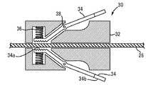
샤프트 조작기는 통상적으로 로킹 해제 위치에 있는 것으로서 설명되었지만, 다른 실시예에서 샤프트 조작기는 사용자가 죠(jaw)를 폐쇄하기보다 죠를 개방하기 위해 죠 상에 압력을 인가하도록 통상적으로 로킹 위치에 있을 수 있다. 도2a 내지 도2d는 통상적으로 로킹 위치에 있도록 구성되는 샤프트 조작기(30)를 도시하고 있다. 조작기(30)는 샤프트(26)에 회전 가능하게 그리고 활주 가능하게 결합되고, 한손 사용을 위해 구성된다. 조작기(30)는 내강(31)을 갖는 본체(32), 암(34), 스프링(36) 그리고 피벗 핀(38)을 포함한다. 암(34)은 피벗 핀이 활주 가능하게 끼워지는 구멍을 그 내에 갖고, 표면(34a)을 갖고, 확장될 수 있는 단부(34b)를 갖는다. 본체(32), 암(34), 표면(34a), 스프링(36) 및 피벗 핀(38)은 각각 본체(12), 버튼(14), 표면(14a), 스프링(16) 및 피벗 핀(38)에 대해 실질적으로 위에서 설명된 것과 같은 재료로부터 제조, 제작 및 조립될 수 있다.Although the shaft manipulator is typically described as being in the unlocked position, in other embodiments the shaft manipulator may typically be in the locked position such that the user applies pressure on the jaw to open the jaw rather than close the jaw. have. 2A-2D show a
조작기(30)는 정상상태에서 샤프트(26)와 마찰 접촉하기 위해 암(34)의 표면(34a)을 가압하도록 스프링(36)이 연장되는 로킹 위치에 있다(도2c). 조작기는 통상적으로 사용자가 샤프트(26)를 용이하게 회전 또는 병진 이동시키게(또는 양쪽 모두를 수행하게) 하도록 로킹된다. 사용자는 샤프트(26)와 접촉 해제하기 위해 표면(34a)을 가압하도록 서로를 향해 암(34b)을 가압함으로써 샤프트(26)를 따른 임의의 요구 위치까지 한 손으로 조작기(30)를 이동시킬 수 있고(도2d), 그에 후속하여 샤프트(26) 상에서의 조작기(30)의 회전 또는 병진 이동(또는 양쪽 모두)이 수행될 수 있다. 예컨대, 사용자는 절개부의 근처 또는 유도 시스 근처의 샤프트의 일부분과 같은 샤프트의 노출 말단 부분까지 한 손으로 조작기를 이동시킬 수 있다. 조작기를 사용하는 장점에 따르면, 이것은 샤프트를 따라 용이하게 위치될 수 있고, 다른 손이 핸들(28)을 붙잡고 있는 동안에 한 손으로 조작될 수 있다.
도2a 내지 도2d의 카테테르 및 조작기의 사용이 이제부터 설명될 것이다. 카테테르(20)는 임의의 알려진 방식으로 환자 내로 유도된다. 사용자가 카테테르를 조작하고 싶을 때에, 사용자는 조작기(30)를 파지하여 샤프트(26)와의 마찰 접촉 상태로부터 이탈되게 표면(34a)을 이동시키도록 단부(34b) 상에서의 가압에 의해 샤프트로부터 조작기를 로킹 해제한다. 그 다음에, 사용자가 카테테르를 조작하기 적절한 위치까지 조작기(30)를 이동시킨다. 그 다음에, 단부(34b)를 가압하여 스프링(36)이 샤프트(26)와 마찰 접촉 상태로 표면(34a)을 이동시키게 하도록 제거된다. 그 다음에, 조작기가 아테롬 등의 조직과 접촉 상태로 커터(22)의 회전, 병진 이동 또는 양쪽 모두를 수행하기 위해 회전 또는 병진 이동되거나 양쪽 모두가 수행된다. 일부 실시예에서, 커터(22)는 반경 방향으로 창(24)의 외부측으로 연장되고, 카테테르(20)는 커터(22)가 아테롬을 절단하도록 연장된 상태로 혈관을 통해 전진된다. 일부 실시예에서, 아테롬은 커터(22)에 의해 카테테르의 내부 내로 안내된다.The use of the catheter and manipulator of FIGS. 2A-2D will now be described.
도3a 및 도3b의 실시예를 참조하면, 조작기(45)와 사용되는 또 다른 카테테르(40)가 도시되어 있다. 카테테르(40)는 위에서 설명된 카테테르(20)와 유사할 수 있지만, 위에서 설명된 샤프트(26)와 유사한 샤프트(46) 또는 또 다른 샤프트를 갖는 작업 요소를 구비한 임의의 또 다른 카테테르일 수 있고, 어느 경우에나 루프(loop)(42)가 추가된다. 조작기(45)는 위에서 설명된 조작기(10, 30)를 포함할 수 있거나, 또 다른 조작기일 수 있다. 핸들(48)은 위에서 설명된 핸들(28)과 유사할 수 있지만, 임의의 다른 핸들일 수 있다.Referring to the embodiment of Figures 3A and 3B, another
카테테르(40)는 조작기와 핸들 사이에 위치되는 루프(42)를 갖는 샤프트(46)를 포함한다. 루프(42)는 샤프트가 조작될 때에 루프를 형성하도록 설계되는 가요성 카테테르 부분으로 형성될 수 있거나, 사전-성형 루프 카테테르 부분일 수 있고, 형성될 때에 간극(44)을 포함한다. 샤프트(46)는 샤프트가 핸들에 대해 회전 또는 병진 이동되지 않도록 핸들(48)에 견고하게 결합된다. 조작기(45)가 회전 또는 병진 이동될 때에, 루프(42)는 핸들의 배향 또는 위치 면에서의 변화를 요구하지 않으면서 샤프트의 말단 단부가 조작기에 의해 회전 또는 병진 이동되게 할 정도로 충분히 가요성이다. 핸들(48)에 대한 샤프트(46)의 회전 또는 병진 이동 중에, 루프(42)는 직경(47) 면에서 더 커지거나 더 작아질 수 있고, 간극(44)은 핸들(48)이 미변화 위치에 남아 있게 하는 동안에 샤프트(46)의 회전 또는 병진 이동을 수용하도록 증가 또는 감소되거나 양쪽 모두가 수행될 수 있다.The
도3a 및 도3b의 카테테르의 사용이 이제부터 설명될 것이다. 카테테르는 임의의 알려진 방식으로 환자 내로 유도된다. 사용자가 카테테르를 조작하고 싶을 때에, 사용자는 조작기를 파지하여 카테테르를 조작하기 적절한 위치까지 이것을 이동시킨다. 그 다음에, 사용자가 샤프트 상으로 조작기를 로킹한다. 샤프트가 조작됨에 따라, 루프가 핸들 위치가 미변화 상태로 남아 있는 동안에 샤프트를 회전, 병진 이동 또는 양쪽 모두를 수용하기 위해 필요에 따라 간극을 수축, 팽창 또는 변화시킬 것이다. 일부 실시예에서, 커터(22)는 반경 방향으로 창(24)의 외부측으로 연장되고, 카테테르(20)는 커터(22)가 아테롬을 절단하도록 연장된 상태로 혈관을 통해 전진된다. 일부 실시예에서, 아테롬은 커터(22)에 의해 카테테르의 내부 내로 안내된다.The use of the catheter of FIGS. 3A and 3B will now be described. The catheter is guided into the patient in any known manner. When the user wants to operate the catheter, the user grips the manipulator and moves it to a position suitable for operating the catheter. The user then locks the manipulator onto the shaft. As the shaft is manipulated, the loop will deflate, inflate or change the gap as necessary to accommodate rotation, translational movement, or both, while rotating the shaft while the handle position remains unchanged. In some embodiments, the
도4a 및 도4b는 조작기(55)와 사용되는 또 다른 카테테르(50)를 도시하고 있다. 샤프트의 말단 부분이 부착력(apposition force)을 제공하여 혈관 벽에 대해 절단 요소를 압박하도록 성형된다. 카테테르(50)는 위에서 설명된 카테테르(20)와 유사할 수 있지만, 위에서 설명된 샤프트(26)와 유사한 샤프트(56) 또는 또 다른 샤프트를 갖는 작업 요소를 구비한 임의의 다른 카테테르일 수 있고, 어느 경우에나 조그(jog)(51j) 및 사전-형성 굽힘부(preformed bend)(51p, 51d)가 추가된다. 조작기(50)가 또한 각각 작업 요소(22) 및 창(24)과 구성, 재료 및 기능 면에서 유사할 수 있는 작업 요소(52) 및 창(54)을 포함한다. 창(54)은 카테테르가 혈관 내에 위치될 때에 작업 요소(52)가 혈관 벽에 대해 압박되도록 샤프트 상의 반경 방향 내향 위치에 위치된다. 조그(51j) 및 사전-형성 굽힘부(51p, 51d)는 혈관 내에서 절단될 물질과 접촉 상태로 작업 요소(52)를 압박하도록 협력한다. 조작기(55)는 위에서 설명된 조작기(10, 30)를 포함할 수 있거나, 또 다른 조작기일 수 있다. 카테테르(50)와의 조작기(55)의 사용은 선택 사항이다. 핸들(58)은 위에서 설명된 핸들(28)과 유사할 수 있지만, 임의의 다른 핸들일 수 있다.4A and 4B show another
카테테르 샤프트(56)는 조그(51j) 및 사전-형성 굽힘부(51p, 51d)를 포함한다. 조그(51j)는 샤프트(56)의 말단 부분(56d)이 샤프트(56)의 중간 부분(56m)과 관련하여 급격하게 굽혀지게 하는 힌지 구조물을 포함한다. 조그가 가능한 카테테르 구조물은 2004년 7월 21일자로 출원되고 제US 2005/0177068 A1호로서 공개된 미국 특허 출원 10/896,741호의 문단 [0092] 내지 [0094], [0100] 내지 [0102], [0105] 내지 [0107] 그리고 도1, 도1A, 도2, 도4A 및 도4B에 추가로 기재되어 있다. US 특허 공개 제US 2005/0177068호의 전체 내용은 온전히 여기에 합체되어 있다. 하나의 실시예에서, 사전-형성 굽힘부는 중간 부분 그리고 중간 부분에 근접한 카테테르 샤프트의 부분이 제1 평면 내에 놓이도록 형성되고, 힌지 요소는 단지 제1 평면 내에서의 중간 부분에 대한 말단 부분의 굽힘을 허용하도록 구성된다. 사전-형성 굽힘부(51p, 51d)는 카테테르(56)가 몰드의 형상을 취하게 하기 위해 금속 몰드 내에 말단 부분(56d)을 구속하고 그에 후속되는 열의 인가에 의해 또는 당업자에게 공지된 것과 같은 다른 수단에 의해 형성될 수 있다. 사전-형성 굽힘부(51p)는 사전-형성 굽힘부(51d)의 각도(53d)보다 작은 각도(53p)를 갖는다. 90˚ 내지 150˚의 사전-형성 굽힘부(51p)의 각도가 고려된다. 하나의 실시예에서, 사전-형성 굽힘부(51p)의 각도는 100˚ 내지 120˚이다. 다른 실시예에서, 각도(53p)는 95˚, 105˚, 110˚, 115˚, 125˚, 130˚ 또는 140˚이다. 100˚ 내지 180˚의 사전-형성 굽힘부(51d)의 각도(53d)가 고려된다. 하나의 실시예에서, 사전-형성 굽힘부(51d)의 각도는 120˚ 내지 140˚이다. 다른 실시예에서, 각도(53d)는 110˚, 130˚, 150˚, 160˚ 또는 170˚이다. 사전-형성 굽힘부(51p)로부터 사전-형성 굽힘부(51d)까지의 길이는 사전-형성 굽힘부(51d)로부터 조그(51j)까지의 길이보다 대체로 크다. 1.27 ㎝(0.5 인치) 내지 5.08 ㎝(2.0 인치)의 사전-형성 굽힘부(51p)로부터 사전-형성 굽힘부(51d)까지의 길이가 고려된다. 하나의 실시예에서, 사전-형성 굽힘부(51p)로부터 사전-형성 굽힘부(51d)까지의 길이는 2.54 ㎝(1.00 인치) 내지 3.175 ㎝(1.25 인치)이다. 다른 실시예에서, 사전-형성 굽힘부(51p)로부터 사전-형성 굽힘부(51d)까지의 길이는 1.905 ㎝(0.75 인치), 3.81 ㎝(1.5 인치) 또는 4.445 ㎝(1.75 인치)이다. 0.3175 ㎝(0.125 인치) 내지 2.54 ㎝(1.0 인치)의 사전-형성 굽힘부(51d)로부터 조그(51j)까지의 길이가 고려된다. 하나의 실시예에서, 사전-형성 굽힘부(51d)로부터 조그(51e)까지의 길이는 0.9525 ㎝(0.375 인치) 내지 1.5875 ㎝(0.625 인치)이다. 일부 실시예에서, 사전-형성 굽힘부(51d)로부터 조그(51j)까지의 길이는 0.635 ㎝(0.25 인치), 1.27 ㎝(0.5 인치), 1.905 ㎝(0.75 인치) 또는 2.2225 ㎝(0.875 인치)이다. 조합 굽힘부(51d, 51p), 그리고 굽힘부들 사이 그리고 굽힘부와 조그 사이의 길이는 카테테르(56)가 카테테르(56)의 굽혀지지 않은 부분으로부터 조그(56j)까지의 최대 변위(56e)를 갖게 한다. 일반적으로, 본 발명의 카테테르는 카테테르(50)가 사용될 혈관 또는 도관의 직경보다 큰 변위를 갖도록 선택된다. 3 ㎜ 내지 40 ㎜의 변위(56e)가 고려된다. 하나의 실시예에서, 변위(56e)는 5 ㎜ 내지 8 ㎜이다. 일부 실시예에서, 변위(56e)는 4 ㎜, 5 ㎜, 6 ㎜, 7 ㎜, 8 ㎜, 10 ㎜, 12 ㎜, 15 ㎜, 20 ㎜, 25 ㎜, 30 ㎜ 또는 35 ㎜이다.The
카테테르(50)가 미구속 변위(56e)보다 작은 직경(D)의 혈관(V)의 내부측에 위치될 때에, 사전-형성 굽힘부(51p, 51d)는 조그(51j)로 인해 카테테르(50)의 가장 말단 부분이 혈관(V)의 내부 벽을 따라 배향될 수 있는 상태에서 그들의 미편향 사전-형성 각도보다 큰 각도를 취하도록 가압된다. 조그(56j)와 굽힘부(51p, 51d) 사이의 이러한 협력은 사전-형성 굽힘부가 그 미편향 사전-형성 각도를 회복하려고 하기 때문에 혈관(V)의 내부 벽과 접촉 상태로 창(54)을 가압 또는 압박한다. 사전-형성 굽힘부(51d)는 혈관 직경부의 하부 단부에서 혈관(V)의 내부 벽에 대한 커터(52) 및 창(54)의 부착력을 유지한다. 혈관 직경이 증가됨에 따라, 사전-형성 굽힘부(51p)는 결국 카테테르 팁에 또한 부착력을 인가하기 시작한다. 0.02268 ㎏(0.05 파운드) 내지 0.226796 ㎏(0.5 파운드)의 압박력이 고려된다. 하나의 실시예에서, 압박력은 0.045359 ㎏(0.1 파운드)이다. 일부 실시예에서, 압박력은 0.034019 ㎏(0.075 파운드), 0.090718 ㎏(0.2 파운드), 0.136078 ㎏(0.3 파운드) 또는 0.181437 ㎏(0.4 파운드)이다. 커터 등의 작업 요소(52)는 아테롬 등의 절단될 물질과 접촉되도록 창(54)을 통해 연장될 수 있다. 절단 중에, 혈관의 내부측 표면으로부터 이탈되게 커터를 편향시키기 쉬운 절단력이 위에서 설명된 것과 같이 생성된 압박력에 의해 저항을 받을 것이다. 샤프트(56)의 말단 부분은 창(54)이 절단될 물질과 접촉되도록 원주 방향으로 배향되는 것을 보증하기 위해 (사용된다면) 조작기(55)에 의해 회전 또는 병진 이동되거나 양쪽 모두가 수행될 수 있다.When the
도4a 및 도4b의 카테테르의 사용이 이제부터 설명될 것이다. 혈관(V)의 내부측 직경보다 큰 변위(56e)를 갖는 카테테르(50)가 선택된다. 선택적으로, 카테테르는 물질이 제거되어야 하는 혈관(V) 내의 위치까지 임의의 알려진 방식으로 환자 내로 안내 와이어(guidewire)를 거쳐 유도된다. 카테테르는 안내 와이어를 거쳐 유도될 때에 약간 직선화되어 그 위치까지 안내 와이어를 따르기 쉽다. 사전-형성 굽힘부(51p, 51d)는 조그(51j)와 협력하여 혈관(V)의 내부 벽에 대해 창(54)을 압박한다. 일부 실시예에서, 커터(52)는 반경 방향으로 창(54)의 외부측으로 연장되고, 카테테르(50)는 커터(52)가 아테롬을 절단하도록 연장된 상태로 혈관을 통해 전진된다. 일부 실시예에서, 아테롬은 커터(52)에 의해 카테테르의 내부 내로 안내된다. 선택적으로, 사용자가 카테테르를 조작하고 싶을 때에, 사용자는 조작기(55)를 파지하여 카테테르를 조작하기 적절한 위치까지 이것을 이동시킨다. 그 다음에, 사용자가 샤프트(56) 상으로 조작기를 로킹하고, 핸들(58)의 위치가 미변화 상태로 남아 있는 동안에 샤프트를 회전 또는 병진 이동시키거나 양쪽 모두를 수행한다.The use of the catheter of FIGS. 4A and 4B will now be described. The
도5a 내지 도5c는 조작기(65)와 사용되는 또 다른 카테테르(60)를 도시하고 있다. 샤프트의 말단 부분이 부착력을 제공하여 혈관 벽에 대해 절단 요소를 압박하도록 성형된다. 카테테르(60)는 위에서 설명된 카테테르(20)와 유사할 수 있지만, 위에서 설명된 샤프트(26)와 유사한 샤프트(66) 또는 또 다른 샤프트를 갖는 작업 요소를 구비한 임의의 다른 카테테르일 수 있고, 어느 경우에나 조그(61j) 및 연속 감소 반경 곡선부(continuously decreasing radius curve)(61)가 추가된다. 조그(61j)는 조그(51j)와 구성, 재료 및 기능 면에서 유사할 수 있다. 카테테르(60)가 또한 각각 작업 요소(22) 및 창(24)과 구성, 재료 및 기능 면에서 유사할 수 있는 작업 요소(62) 및 창(64)을 포함한다. 작업 요소(62)는 카테테르가 혈관 내에 위치될 때에 작업 요소(62)가 혈관 벽에 대해 압박되도록 샤프트 상의 반경 방향 내향 위치에 위치된다. 조그(61j) 및 연속 감소 반경 곡선부(61)는 혈관 내의 절단될 물질과 접촉 상태로 작업 요소(62)를 압박하도록 협력한다. 조작기(65)는 위에서 설명된 조작기(10, 30)를 포함할 수 있거나, 또 다른 조작기일 수 있다. 카테테르(60)와의 조작기(65)의 사용은 선택 사항이다. 핸들(68)은 위에서 설명된 핸들(28)과 유사할 수 있지만, 임의의 다른 핸들일 수 있다.5A-5C show another
카테테르 샤프트(66)는 조그(61j) 및 연속 감소 반경 곡선부(61)를 포함한다. 연속 감소 반경 곡선부(61)는 말단 부분(66d)이 몰드의 형상을 취하게 하기 위해 금속 몰드 내에 카테테르 샤프트(66)의 말단 부분(66d)을 구속하고 그에 후속하여 열을 인가함으로써 또는 당업자에게 공지된 것과 같은 다른 수단에 의해 형성될 수 있다. 말단 부분(66d)은 적어도 90˚ 내지 적어도 720˚까지 감길 수 있다. 도5a는 약 360˚만큼 감긴 샤프트를 도시하고 있고, 도5b는 약 720˚만큼 감긴 샤프트를 도시하고 있다. 다른 실시예에서, 말단 단부(66d)는 120˚, 150˚, 180˚, 240˚, 300˚, 480˚ 또는 600˚만큼 감긴다. 최대 곡선부 직경(63)은 3 ㎜ 내지 50 ㎜의 범위 내에서 변동될 수 있지만, 최대 곡선부 직경은 특정 적용 분야에 따라 이러한 범위의 외부측에 있을 수 있다. 하나의 실시예에서, 최대 곡선부 직경은 10 ㎜ 내지 12 ㎜이다. 다른 실시예에서, 최대 곡선부 직경은 4 ㎜, 6 ㎜, 8 ㎜, 15 ㎜, 20 ㎜, 25 ㎜, 30 ㎜ 또는 40 ㎜이다.The
또 다른 실시예에서, 연속 감소 반경 곡선부(61)는 (도시되지 않은) 다수개의 불연속 사전-형성 굽힘부를 포함할 수 있다. 이해될 수 있는 것과 같이, 감소 반경부의 섹션의 개수는 변동될 수 있다. 예컨대, 2개 내지 100개의 섹션을 갖는 카테테르가 고려된다. 다른 실시예에서, 카테테르는 4개, 6개, 8개, 10개, 15개, 20개, 40개, 60개, 75개 또는 100개의 섹션을 가질 수 있다. 또 다른 실시예에서, 카테테르는 도5a 내지 도5c의 연소 가변 실시예에 의해 개시된 것과 같이 무한 개수의 섹션을 갖는다.In yet another embodiment, the continuous decreasing
연속 감소 반경부는 소정 범위의 혈관 직경에 걸쳐 비교적 균일한 부착력을 제공하도록 의도된다. 물론, 실제의 부착력은 혈관 기하 형상 및 크기가 환자마다 상당히 변동되기 때문에 사용 중에 상당히 변동될 수 있지만, 샤프트의 형상은 소정 범위의 혈관 크기에 걸쳐 균일한 힘을 제공하기 쉽다.The continuous reduction radius is intended to provide a relatively uniform adhesion over a range of vessel diameters. Of course, the actual adhesion may vary considerably during use because the vessel geometry and size vary significantly from patient to patient, but the shape of the shaft tends to provide uniform force over a range of vessel sizes.
카테테르(60)가 최대 곡선부 직경(63)보다 작은 직경(D)의 혈관(V)의 내부측에 위치될 때에, 연속 감소 반경 곡선부(61)는 조그(61j)가 카테테르(60)의 가장 말단 부분이 혈관(V)의 내부 벽을 따라 배향되는 동안에 직경 면에서 증가되도록 가압된다. 조그(56j)와 곡선부(61) 사이의 이러한 협력은 곡선부(61)가 그 미변형 직경을 회복하려고 하기 때문에 혈관(V)의 내부 벽과 접촉 상태로 창(64)을 가압 또는 압박한다. 커터 등의 작업 요소(62)는 아테롬 등의 절단될 물질과 접촉되도록 창(64)을 통해 연장될 수 있다. 절단 중에, 혈관의 내부측 표면으로부터 이탈되게 커터를 편향시키기 쉬운 절단력이 위에서 설명된 것과 같이 생성된 압박력에 의해 저항을 받을 것이다. 샤프트(66)의 말단 부분은 창(64)이 절단될 물질과 접촉되도록 원주 방향으로 배향되는 것을 보증하기 위해 (사용된다면) 조작기(65)에 의해 회전 또는 병진 이동되거나 양쪽 모두가 수행될 수 있다.When the
도5a 내지 도5c의 카테테르의 사용이 이제부터 설명될 것이다. 카테테르는 물질이 제거되어야 하는 위치까지 임의의 알려진 방식으로 환자 내로 안내 와이어를 거쳐 유도된다. 카테테르는 안내 와이어를 거쳐 유도될 때에 약간 직선화되어 그 위치까지 안내 와이어를 따르기 쉽다. 곡선부(61)는 조그(61j)와 협력하여 혈관(V)의 내부 벽에 대해 창(64)을 압박한다. 일부 실시예에서, 커터(62)는 반경 방향으로 창(64)의 외부측으로 연장되고, 카테테르(60)는 커터(62)가 아테롬을 절단하도록 연장된 상태로 혈관을 통해 전진된다. 일부 실시예에서, 아테롬은 커터(62)에 의해 카테테르의 내부 내로 안내된다. 선택적으로, 사용자가 카테테르를 조작하고 싶을 때에, 사용자는 조작기(65)를 파지하여 카테테르를 조작하기 적절한 위치까지 이것을 이동시킨다. 그 다음에, 사용자가 샤프트(66) 상으로 조작기를 로킹하고, 핸들(68)의 위치가 미변화 상태로 남아 있는 동안에 샤프트를 회전 또는 병진 이동시키거나 양쪽 모두를 수행한다.The use of the catheter of FIGS. 5A-5C will now be described. The catheter is guided through the guide wire into the patient in any known manner up to the location where the material should be removed. The catheter is slightly straightened when guided through the guide wire and tends to follow the guide wire to its location.
본 발명은 양호한 실시예와 연계하여 설명되었지만, 물론 위에서 설명된 예시 실시예로부터 벗어나지 않고도 실시될 수 있다.
Although the invention has been described in connection with the preferred embodiment, it can of course be practiced without departing from the exemplary embodiment described above.
Claims (52)
Translated fromKorean말단 및 근접 단부 그리고 내강을 형성하는 측벽을 갖는 긴 튜브형 샤프트로서, 긴 튜브형 샤프트는 근접 굽힘부, 말단 굽힘부 및 힌지 요소를 갖고, 근접 굽힘부는 0보다 큰 제1 각도를 형성하고, 말단 굽힘부는 제1 각도보다 큰 제2 각도를 형성하고, 힌지 요소는 긴 튜브형 샤프트의 말단 단부의 근접 방향으로 그리고 말단 굽힘부의 말단 방향으로 이격되고, 말단 굽힘부는 근접 굽힘부와 힌지 요소 사이에 위치되고, 긴 튜브형 샤프트의 말단 부분이 힌지 요소와 긴 튜브형 샤프트의 말단 단부 사이에서 연장되고, 긴 튜브형 샤프트의 중간 부분이 힌지 요소와 근접 굽힘부 사이에서 연장되고, 말단 부분은 힌지 요소와 긴 튜브형 샤프트의 말단 단부 사이의 측벽을 통해 연장되는 창을 포함하는, 샤프트와;
긴 튜브형 샤프트의 내강 내에 배치되는 작업 요소로서, 작업 요소는 치료 부위에서 창을 통해 시술을 수행하도록 구성되고, 제1 및 제2 각도는 창이 치료 부위에서 혈관의 벽에 대해 압박되도록 직경(D)보다 큰 근접 굽힘부와 힌지 요소 사이의 긴 튜브형 샤프트의 최대 변위를 형성하도록 선택되는 작업 요소를 포함하는 카테테르.A catheter performing a procedure at a treatment site in the lumen of a blood vessel, wherein the blood vessel has a diameter (D) at the treatment site.
An elongated tubular shaft having distal and proximal ends and sidewalls forming a lumen, wherein the elongated tubular shaft has proximal bends, distal bends and hinge elements, the proximal bends forming a first angle greater than zero, and the distal bends Forming a second angle greater than the first angle, the hinge element being spaced in the proximal direction of the distal end of the elongated tubular shaft and in the distal direction of the distal bend, the distal bend being positioned between the proximal bend and the hinge element, The distal end of the tubular shaft extends between the hinge element and the distal end of the elongated tubular shaft, the middle part of the elongated tubular shaft extends between the hinge element and the proximal bend, and the distal end is the distal end of the hinge element and the long tubular shaft. A shaft comprising a window extending through a sidewall between the shaft;
A work element disposed within the lumen of an elongated tubular shaft, the work element being configured to perform a procedure through a window at the treatment site, the first and second angles being diameter (D) such that the window is pressed against the wall of the vessel at the treatment site. A catheter comprising a work element selected to form a maximum displacement of the long tubular shaft between the larger proximal bend and the hinge element.
말단 및 근접 단부 그리고 내강을 형성하는 측벽을 갖는 긴 튜브형 샤프트로서, 긴 튜브형 샤프트는 연속 감소 곡률 반경부를 구비한 곡선형 말단 부분을 갖고, 연속 감소 곡률 반경부는 말단 부분의 근접 단부로부터 긴 튜브형 샤프트의 말단 단부까지 제1 평면 내에 배향되고, 상기 말단 부분은 긴 튜브형 샤프트의 말단 단부의 근접 방향으로 이격되는 힌지 요소를 포함하고, 힌지 요소는 말단 부분을 긴 튜브형 샤프트의 말단 단부와 힌지 요소 사이의 말단 세그먼트 그리고 말단 부분의 근접 단부와 힌지 요소 사이의 근접 세그먼트로 분할하고, 힌지 요소는 말단 세그먼트가 단지 제1 평면 내에서 근접 세그먼트에 대해 굽혀지게 하도록 구성되고, 말단 세그먼트는 힌지 요소와 긴 튜브형 샤프트의 말단 단부 사이의 측벽을 통해 연장되는 창을 포함하는, 샤프트와;
긴 튜브형 샤프트의 내강 내에 배치되는 작업 요소로서, 작업 요소는 치료 부위에서 창을 통해 시술을 수행하도록 구성되고, 연속 감소 곡률 반경부는 사용 중에 치료 부위에서 혈관의 벽에 대해 창을 압박하도록 선택되는 작업 요소를 포함하는 카테테르.Catheter to perform the procedure at the treatment site in the lumen of the blood vessel,
An elongated tubular shaft having distal and proximal ends and sidewalls forming a lumen, wherein the elongated tubular shaft has a curved end portion with a continuous decreasing curvature radius, the continuous decreasing curvature radius of the elongated tubular shaft from the proximal end of the distal portion. Oriented in the first plane up to the distal end, the distal portion comprising a hinge element spaced apart in a proximal direction of the distal end of the elongated tubular shaft, the hinge element distal end being between the distal end and the hinge element of the elongated tubular shaft. Segment and a proximal segment between the proximal end of the distal portion and the hinge element, wherein the hinge element is configured to cause the distal segment to bend relative to the proximal segment in the first plane only, the distal segment of the hinge element and the elongated tubular shaft. A window extending through the sidewalls between the distal ends; , Shafts and;
A work element disposed within the lumen of an elongated tubular shaft, the work element being configured to perform a procedure through a window at the treatment site, the continuous decreasing curvature radius being selected to compress the window against the wall of the vessel at the treatment site during use. Catheter containing the element.
말단 및 근접 단부 그리고 내강을 형성하는 측벽을 갖는 긴 튜브형 샤프트를 제공하는 단계로서, 긴 튜브형 샤프트는 근접 굽힘부, 말단 굽힘부 및 힌지 요소를 갖고, 근접 굽힘부는 0보다 큰 제1 각도를 형성하고, 말단 굽힘부는 제1 각도보다 큰 제2 각도를 형성하고, 근접 및 말단 굽힘부는 제1 방향으로 배향되고, 힌지 요소는 긴 튜브형 샤프트의 말단 단부의 근접 방향으로 그리고 말단 굽힘부의 말단 방향으로 이격되고, 말단 굽힘부는 근접 굽힘부와 힌지 요소 사이에 위치되고, 긴 튜브형 샤프트의 말단 부분이 힌지 요소와 긴 튜브형 샤프트의 말단 단부 사이에서 연장되고, 긴 튜브형 샤프트의 중간 부분이 힌지 요소와 근접 굽힘부 사이에서 연장되고, 말단 부분은 힌지 요소와 긴 튜브형 샤프트의 말단 단부 사이의 측벽을 통해 연장되는 창을 포함하는, 단계와;
치료 부위까지 혈관의 내강을 통해 긴 튜브형 샤프트를 전진시키는 단계와;
근접 및 말단 굽힘부가 긴 튜브형 샤프트의 말단 부분이 치료 부위의 요구 위치에서 혈관의 벽에 대해 창을 압박하기 위해 제1 방향에 대향인 제2 방향으로 힌지 요소에서 긴 튜브형 샤프트의 중간 부분에 대해 굽혀지게 하는 위치에 긴 튜브형 샤프트를 배향하는 단계와;
창이 혈관의 벽에 대해 압박되는 동안에 작업 요소가 긴 튜브형 샤프트의 내강 내에 배치된 상태에서 치료 부위에서 창을 통해 시술을 수행하는 단계를 포함하는 치료 부위 시술 수행 방법.It is a method of performing the procedure at the treatment site in the lumen of the blood vessel,
Providing an elongated tubular shaft having distal and proximal ends and sidewalls forming a lumen, the elongated tubular shaft having a proximal bend, a distal bend and a hinge element, the proximal bend forming a first angle greater than zero and , The end bends form a second angle greater than the first angle, the proximal and end bends are oriented in the first direction, the hinge elements are spaced in the proximal direction of the distal end of the elongated tubular shaft and in the distal direction of the distal bend. The end bend is positioned between the proximal bend and the hinge element, the distal end of the elongated tubular shaft extends between the hinge element and the distal end of the elongated tubular shaft, and the middle portion of the elongated tubular shaft extends between the hinge element and the proximal bend. And a distal end comprising a window extending through the sidewall between the hinge element and the distal end of the elongated tubular shaft. Doing;
Advancing an elongated tubular shaft through the lumen of the vessel to the treatment site;
The proximal and distal bends are bent against the middle portion of the elongated tubular shaft in a hinge element in a second direction opposite the first direction to urge the window against the wall of the blood vessel at the required position of the treatment site. Orienting the elongated tubular shaft in a retracted position;
And performing the procedure through the window at the treatment site with the working element disposed in the lumen of the elongated tubular shaft while the window is pressed against the wall of the vessel.
말단 및 근접 단부 그리고 내강을 형성하는 측벽을 갖는 긴 튜브형 샤프트를 제공하는 단계로서, 긴 튜브형 샤프트는 연속 감소 곡률 반경부를 구비한 곡선형 말단 부분을 갖고, 연속 감소 곡률 반경부는 말단 부분의 근접 단부로부터 긴 튜브형 샤프트의 말단 단부까지 제1 방향으로 배향되고, 상기 말단 부분은 긴 튜브형 샤프트의 말단 단부의 근접 방향으로 이격되는 힌지 요소를 포함하고, 힌지 요소는 말단 부분을 힌지 요소와 긴 튜브형 샤프트의 말단 단부 사이의 말단 세그먼트 그리고 힌지 요소와 말단 부분의 근접 단부 사이의 근접 세그먼트로 분할하고, 힌지 요소는 말단 세그먼트가 단지 제1 방향 그리고 제1 방향에 대향인 제2 방향으로 근접 세그먼트에 대해 굽혀지게 하도록 구성되고, 말단 세그먼트는 힌지 요소와 긴 튜브형 샤프트의 말단 단부 사이의 측벽을 통해 연장되는 창을 포함하는, 단계와;
치료 부위까지 혈관의 내강을 통해 긴 튜브형 샤프트를 전진시키는 단계와;
곡선형 말단 부분의 연속 감소 곡률 반경부가 말단 세그먼트가 치료 부위의 요구 위치에서 혈관의 벽에 대해 창을 압박하기 위해 제2 방향으로 힌지 요소에서 근접 세그먼트에 대해 굽혀지게 하는 위치에 긴 튜브형 샤프트를 배향하는 단계와;
창이 혈관의 벽에 대해 압박되는 동안에 작업 요소가 긴 튜브형 샤프트의 내강 내에 배치된 상태에서 치료 부위에서 창을 통해 시술을 수행하는 단계를 포함하는 치료 부위 시술 수행 방법.It is a method of performing the procedure at the treatment site in the lumen of the blood vessel,
Providing an elongated tubular shaft having a distal and proximal end and a side wall forming a lumen, the elongated tubular shaft having a curved end portion with a continuous decreasing curvature radius, the continuous decreasing curvature radius from a proximal end of the distal portion. Oriented in a first direction up to the distal end of the elongated tubular shaft, the distal portion comprising a hinge element spaced apart in a proximal direction of the distal end of the elongated tubular shaft, the hinge element distally of the distal end of the elongated tubular shaft and the distal end of the elongated tubular shaft. The distal segment between the end and the proximal segment between the hinge element and the proximal end of the distal portion, the hinge element causing the distal segment to bend relative to the proximal segment in only the first direction and in a second direction opposite the first direction. The distal segment comprises a hinge element and a distal end of the elongated tubular shaft A window extending through sidewalls between the ends;
Advancing an elongated tubular shaft through the lumen of the vessel to the treatment site;
The continuous decreasing curvature radius of the curved distal portion orients the elongated tubular shaft in a position such that the distal segment is bent relative to the proximal segment at the hinge element in a second direction to squeeze the window against the wall of the vessel at the desired position of the treatment site. Making a step;
And performing the procedure through the window at the treatment site with the working element disposed in the lumen of the elongated tubular shaft while the window is pressed against the wall of the vessel.
카테테르의 샤프트를 수용하는 크기를 갖는 내강을 구비하는 본체 부분과;
본체 부분 내에 포위되는 제1 및 제2 샤프트 결합 표면을 갖는 샤프트 결합 부재로서, 샤프트 결합 부재는 제1 및 제2 샤프트 결합 표면이 샤프트 상에 본체를 로킹하기 위해 샤프트와 결합되도록 구성되는 로킹 위치 그리고 본체가 긴 튜브형 샤프트에 걸쳐 자유롭게 회전 및 축 방향 병진 이동되는 로킹 해제 위치를 갖는, 샤프트 결합 부재를 포함하는 카테테르 샤프트 조작 장치.In the device for operating the shaft of the catheter,
A body portion having a lumen sized to receive a shaft of the catheter;
A shaft engaging member having first and second shaft engaging surfaces enclosed within the body portion, the shaft engaging member having a locking position configured such that the first and second shaft engaging surfaces are engaged with the shaft to lock the body on the shaft; A catheter shaft manipulation device comprising a shaft engaging member having a unlocked position in which the body is freely rotated and axially translated across an elongated tubular shaft.
말단 및 근접 단부 그리고 내강을 형성하는 측벽을 갖는 긴 튜브형 샤프트로서, 긴 튜브형 샤프트는 제1 굽힘부, 제1 굽힘부의 말단 방향으로 소정 거리만큼 이격되는 제2 굽힘부 그리고 측벽을 통해 연장되는 창을 갖고, 창은 제2 굽힘부의 말단 방향으로 그리고 긴 튜브형 부재의 말단 단부의 근접 방향으로 위치되고, 제1 굽힘부는 0보다 큰 제1 각도를 형성하고, 제2 굽힘부는 제1 각도보다 큰 제2 각도를 형성하고, 제1 및 제2 각도 그리고 소정 거리는 사용 중에 혈관의 벽 상의 부위에 대해 창을 압박하도록 선택되는 샤프트를 포함하는 카테테르.A catheter that accesses a site on the wall of a blood vessel,
An elongated tubular shaft having distal and proximal ends and sidewalls forming a lumen, wherein the elongated tubular shaft comprises a first bend, a second bend spaced a predetermined distance in the distal direction of the first bend and a window extending through the sidewall. And the window is located in the distal direction of the second bend and in the proximal direction of the distal end of the elongated tubular member, the first bend forming a first angle greater than zero, and the second bend formed a second greater than the first angle. And a shaft, wherein the first and second angles and the predetermined distance are selected to squeeze the window against an area on the wall of the blood vessel during use.
말단 및 근접 단부 그리고 내강을 형성하는 측벽을 갖는 긴 튜브형 샤프트로서, 긴 튜브형 샤프트는 근접 굽힘부, 말단 굽힘부 및 힌지 요소를 갖고, 근접 굽힘부는 0보다 큰 제1 각도를 형성하고, 말단 굽힘부는 제1 각도보다 큰 제2 각도를 형성하고, 힌지 요소는 긴 튜브형 샤프트의 말단 단부의 근접 방향으로 그리고 말단 굽힘부의 말단 방향으로 이격되고, 말단 굽힘부는 근접 굽힘부와 힌지 요소 사이에 위치되고, 긴 튜브형 샤프트의 말단 부분이 힌지 요소와 긴 튜브형 샤프트의 말단 단부 사이에서 연장되고, 긴 튜브형 샤프트의 중간 부분이 힌지 요소와 근접 굽힘부 사이에서 연장되고, 말단 부분은 힌지 요소와 긴 튜브형 샤프트의 말단 단부 사이의 측벽을 통해 연장되는 창을 포함하고, 근접 굽힘부, 말단 굽힘부 및 힌지 요소는 치료 부위에서 혈관의 벽에 대해 창을 압박하도록 구성되는 샤프트를 포함하는 카테테르.Catheter to perform the procedure at the treatment site in the lumen of the blood vessel,
An elongated tubular shaft having distal and proximal ends and sidewalls forming a lumen, wherein the elongated tubular shaft has proximal bends, distal bends and hinge elements, the proximal bends forming a first angle greater than zero, and the distal bends Forming a second angle greater than the first angle, the hinge element being spaced in the proximal direction of the distal end of the elongated tubular shaft and in the distal direction of the distal bend, the distal bend being positioned between the proximal bend and the hinge element, The distal end of the tubular shaft extends between the hinge element and the distal end of the elongated tubular shaft, the middle part of the elongated tubular shaft extends between the hinge element and the proximal bend, and the distal end is the distal end of the hinge element and the long tubular shaft. A window extending through the sidewalls therebetween, wherein the proximal bend, the distal bend and the hinge element are at the treatment site. Catheters comprising a shaft that is configured to urge the window against a wall of the tube hotel.
Applications Claiming Priority (4)
| Application Number | Priority Date | Filing Date | Title |
|---|---|---|---|
| US10483608P | 2008-10-13 | 2008-10-13 | |
| US61/104,836 | 2008-10-13 | ||
| US12260108P | 2008-12-15 | 2008-12-15 | |
| US61/122,601 | 2008-12-15 |
Publications (2)
| Publication Number | Publication Date |
|---|---|
| KR20110079898Atrue KR20110079898A (en) | 2011-07-11 |
| KR101645754B1 KR101645754B1 (en) | 2016-08-04 |
Family
ID=41664939
Family Applications (1)
| Application Number | Title | Priority Date | Filing Date |
|---|---|---|---|
| KR1020117010797AActiveKR101645754B1 (en) | 2008-10-13 | 2009-10-13 | Devices and methods for manipulating a catheter shaft |
Country Status (10)
| Country | Link |
|---|---|
| US (3) | US8414604B2 (en) |
| EP (2) | EP2358282B1 (en) |
| JP (2) | JP5555242B2 (en) |
| KR (1) | KR101645754B1 (en) |
| CN (1) | CN102223847B (en) |
| AU (1) | AU2009303501B2 (en) |
| BR (1) | BRPI0920206A2 (en) |
| CA (1) | CA2739665C (en) |
| RU (1) | RU2503422C2 (en) |
| WO (1) | WO2010045226A2 (en) |
Families Citing this family (79)
| Publication number | Priority date | Publication date | Assignee | Title |
|---|---|---|---|---|
| US7713279B2 (en) | 2000-12-20 | 2010-05-11 | Fox Hollow Technologies, Inc. | Method and devices for cutting tissue |
| US7708749B2 (en) | 2000-12-20 | 2010-05-04 | Fox Hollow Technologies, Inc. | Debulking catheters and methods |
| US8328829B2 (en) | 1999-08-19 | 2012-12-11 | Covidien Lp | High capacity debulking catheter with razor edge cutting window |
| US6299622B1 (en) | 1999-08-19 | 2001-10-09 | Fox Hollow Technologies, Inc. | Atherectomy catheter with aligned imager |
| JP4080874B2 (en) | 2000-12-20 | 2008-04-23 | フォックス ハロウ テクノロジーズ,インコーポレイティド | Bulking catheter |
| US8246640B2 (en) | 2003-04-22 | 2012-08-21 | Tyco Healthcare Group Lp | Methods and devices for cutting tissue at a vascular location |
| US20070276419A1 (en) | 2006-05-26 | 2007-11-29 | Fox Hollow Technologies, Inc. | Methods and devices for rotating an active element and an energy emitter on a catheter |
| US8784440B2 (en) | 2008-02-25 | 2014-07-22 | Covidien Lp | Methods and devices for cutting tissue |
| US9125562B2 (en) | 2009-07-01 | 2015-09-08 | Avinger, Inc. | Catheter-based off-axis optical coherence tomography imaging system |
| US8696695B2 (en) | 2009-04-28 | 2014-04-15 | Avinger, Inc. | Guidewire positioning catheter |
| US9788790B2 (en) | 2009-05-28 | 2017-10-17 | Avinger, Inc. | Optical coherence tomography for biological imaging |
| US8414604B2 (en) | 2008-10-13 | 2013-04-09 | Covidien Lp | Devices and methods for manipulating a catheter shaft |
| CN102625673B (en) | 2009-04-29 | 2014-12-24 | 泰科保健集团有限合伙公司 | Methods and devices for cutting and abrading tissue |
| WO2010132748A1 (en) | 2009-05-14 | 2010-11-18 | Fox Hollow Technologies, Inc. | Easily cleaned atherectomy catheters and methods of use |
| WO2011003006A2 (en) | 2009-07-01 | 2011-01-06 | Avinger, Inc. | Atherectomy catheter with laterally-displaceable tip |
| WO2011068932A1 (en) | 2009-12-02 | 2011-06-09 | Fox Hollow Technologies, Inc. | Methods and devices for cutting tissue |
| WO2011072068A2 (en) | 2009-12-08 | 2011-06-16 | Avinger, Inc. | Devices and methods for predicting and preventing restenosis |
| CN102695463B (en) | 2009-12-11 | 2015-01-14 | 泰科保健集团有限合伙公司 | Material removal device having improved material capture efficiency and methods of use |
| RU2538174C2 (en) | 2010-06-14 | 2015-01-10 | Ковидиен Лп | Device for material removal |
| US10548478B2 (en) | 2010-07-01 | 2020-02-04 | Avinger, Inc. | Balloon atherectomy catheters with imaging |
| US9345510B2 (en) | 2010-07-01 | 2016-05-24 | Avinger, Inc. | Atherectomy catheters with longitudinally displaceable drive shafts |
| WO2014039096A1 (en) | 2012-09-06 | 2014-03-13 | Avinger, Inc. | Re-entry stylet for catheter |
| US11382653B2 (en) | 2010-07-01 | 2022-07-12 | Avinger, Inc. | Atherectomy catheter |
| US10085742B2 (en)* | 2010-07-29 | 2018-10-02 | Boston Scientific Scimed, Inc. | Adjustable device for delivering implants and methods of delivering implants |
| CA2815186C (en) | 2010-10-28 | 2015-12-29 | Covidien Lp | Material removal device and method of use |
| KR20150020240A (en) | 2010-11-11 | 2015-02-25 | 코비디엔 엘피 | Flexible debulking catheters with imaging and methods of use and manufacture |
| CN103153381B (en)* | 2011-02-25 | 2014-12-03 | 泰尔茂株式会社 | Fixtures and Conduit Kits |
| US9949754B2 (en) | 2011-03-28 | 2018-04-24 | Avinger, Inc. | Occlusion-crossing devices |
| EP2691038B1 (en) | 2011-03-28 | 2016-07-20 | Avinger, Inc. | Occlusion-crossing devices, imaging, and atherectomy devices |
| US8840630B2 (en) | 2011-06-15 | 2014-09-23 | Cook Medical Technologies Llc | Button release handle |
| EP2750862B1 (en) | 2011-09-01 | 2016-07-06 | Covidien LP | Catheter with helical drive shaft and methods of manufacture |
| EP3653151A1 (en) | 2011-10-17 | 2020-05-20 | Avinger, Inc. | Atherectomy catheters and non-contact actuation mechanism for catheters |
| US9345406B2 (en) | 2011-11-11 | 2016-05-24 | Avinger, Inc. | Occlusion-crossing devices, atherectomy devices, and imaging |
| US9351757B2 (en) | 2012-01-17 | 2016-05-31 | Covidien Lp | Material removal device and method of use |
| US9557156B2 (en) | 2012-05-14 | 2017-01-31 | Avinger, Inc. | Optical coherence tomography with graded index fiber for biological imaging |
| EP2849660B1 (en) | 2012-05-14 | 2021-08-25 | Avinger, Inc. | Atherectomy catheter drive assemblies |
| WO2013172970A1 (en) | 2012-05-14 | 2013-11-21 | Avinger, Inc. | Atherectomy catheters with imaging |
| US9498247B2 (en) | 2014-02-06 | 2016-11-22 | Avinger, Inc. | Atherectomy catheters and occlusion crossing devices |
| US11284916B2 (en) | 2012-09-06 | 2022-03-29 | Avinger, Inc. | Atherectomy catheters and occlusion crossing devices |
| US9532844B2 (en) | 2012-09-13 | 2017-01-03 | Covidien Lp | Cleaning device for medical instrument and method of use |
| US9943329B2 (en) | 2012-11-08 | 2018-04-17 | Covidien Lp | Tissue-removing catheter with rotatable cutter |
| EP2931151B1 (en) | 2012-12-12 | 2019-11-27 | Covidien LP | Tissue-removing catheter including urging mechanism |
| WO2014143064A1 (en) | 2013-03-15 | 2014-09-18 | Avinger, Inc. | Chronic total occlusion crossing devices with imaging |
| CN105228514B (en) | 2013-03-15 | 2019-01-22 | 阿维格公司 | Optical Pressure Sensor Assembly |
| US11096717B2 (en) | 2013-03-15 | 2021-08-24 | Avinger, Inc. | Tissue collection device for catheter |
| EP3019096B1 (en) | 2013-07-08 | 2023-07-05 | Avinger, Inc. | System for identification of elastic lamina to guide interventional therapy |
| US9456843B2 (en)* | 2014-02-03 | 2016-10-04 | Covidien Lp | Tissue-removing catheter including angular displacement sensor |
| US9526519B2 (en)* | 2014-02-03 | 2016-12-27 | Covidien Lp | Tissue-removing catheter with improved angular tissue-removing positioning within body lumen |
| MX2016010141A (en) | 2014-02-06 | 2017-04-06 | Avinger Inc | Atherectomy catheters and occlusion crossing devices. |
| JP5954747B2 (en)* | 2014-03-20 | 2016-07-20 | 朝日インテック株式会社 | catheter |
| WO2015200702A1 (en) | 2014-06-27 | 2015-12-30 | Covidien Lp | Cleaning device for catheter and catheter including the same |
| US10357277B2 (en) | 2014-07-08 | 2019-07-23 | Avinger, Inc. | High speed chronic total occlusion crossing devices |
| US10314667B2 (en) | 2015-03-25 | 2019-06-11 | Covidien Lp | Cleaning device for cleaning medical instrument |
| US10568520B2 (en) | 2015-07-13 | 2020-02-25 | Avinger, Inc. | Micro-molded anamorphic reflector lens for image guided therapeutic/diagnostic catheters |
| US10292721B2 (en) | 2015-07-20 | 2019-05-21 | Covidien Lp | Tissue-removing catheter including movable distal tip |
| US10179046B2 (en)* | 2015-08-14 | 2019-01-15 | Edwards Lifesciences Corporation | Gripping and pushing device for medical instrument |
| US10314664B2 (en) | 2015-10-07 | 2019-06-11 | Covidien Lp | Tissue-removing catheter and tissue-removing element with depth stop |
| CN108368715B (en)* | 2015-10-19 | 2020-03-13 | 伊利诺斯工具制品有限公司 | Door handle incorporating dual hinged sound attenuating flap feature |
| JP6927986B2 (en) | 2016-01-25 | 2021-09-01 | アビンガー・インコーポレイテッドAvinger, Inc. | OCT imaging catheter with delay compensation |
| EP3435892B1 (en) | 2016-04-01 | 2024-04-03 | Avinger, Inc. | Atherectomy catheter with serrated cutter |
| US10456161B2 (en)* | 2016-04-14 | 2019-10-29 | Covidien Lp | Tissue-removing catheter with adjustment mechanism |
| US9962180B2 (en) | 2016-04-27 | 2018-05-08 | Covidien Lp | Catheter including drive assembly for rotating and reciprocating tissue-removing element |
| US11344327B2 (en) | 2016-06-03 | 2022-05-31 | Avinger, Inc. | Catheter device with detachable distal end |
| WO2018006041A1 (en)* | 2016-06-30 | 2018-01-04 | Avinger, Inc. | Atherectomy catheter with shapeable distal tip |
| MA46282A (en)* | 2016-09-21 | 2019-07-31 | 3Nt Medical Ltd | DILATOR RESEARCHER |
| US20180311468A1 (en)* | 2017-04-27 | 2018-11-01 | The Regents Of The University Of California | Force sensor and monitoring device |
| US10137447B1 (en) | 2017-05-17 | 2018-11-27 | Biotix, Inc. | Ergonomic fluid handling tubes |
| US10874839B2 (en)* | 2017-07-13 | 2020-12-29 | Acclarent, Inc. | Adjustable instrument for dilation of anatomical passageway |
| US12167867B2 (en) | 2018-04-19 | 2024-12-17 | Avinger, Inc. | Occlusion-crossing devices |
| CN114746033B (en) | 2019-10-18 | 2025-01-10 | 阿维格公司 | Blocking crossing device |
| US20220392065A1 (en) | 2020-01-07 | 2022-12-08 | Cleerly, Inc. | Systems, methods, and devices for medical image analysis, diagnosis, risk stratification, decision making and/or disease tracking |
| US11969280B2 (en) | 2020-01-07 | 2024-04-30 | Cleerly, Inc. | Systems, methods, and devices for medical image analysis, diagnosis, risk stratification, decision making and/or disease tracking |
| US11501436B2 (en) | 2020-01-07 | 2022-11-15 | Cleerly, Inc. | Systems, methods, and devices for medical image analysis, diagnosis, risk stratification, decision making and/or disease tracking |
| US12318161B2 (en) | 2021-10-05 | 2025-06-03 | Siemens Healthineers Endovascular Robotics, Inc. | Robotic actuation of elongated medical devices |
| US20250032149A1 (en)* | 2021-12-06 | 2025-01-30 | Avinger, Inc. | Atherectomy catheter with shapeable distal tip |
| CN114470487B (en)* | 2021-12-22 | 2023-02-14 | 广东博迈医疗科技股份有限公司 | Medical guide wire and interventional medical equipment |
| US12406365B2 (en) | 2022-03-10 | 2025-09-02 | Cleerly, Inc. | Systems, devices, and methods for non-invasive image-based plaque analysis and risk determination |
| US20250143657A1 (en) | 2022-03-10 | 2025-05-08 | Cleerly, Inc. | Systems, devices, and methods for non-invasive image-based plaque analysis and risk determination |
| US20250217981A1 (en) | 2022-03-10 | 2025-07-03 | Cleerly, Inc. | Systems, methods, and devices for image-based plaque analysis and risk determination |
Citations (3)
| Publication number | Priority date | Publication date | Assignee | Title |
|---|---|---|---|---|
| US4781186A (en)* | 1984-05-30 | 1988-11-01 | Devices For Vascular Intervention, Inc. | Atherectomy device having a flexible housing |
| US20050177068A1 (en)* | 2000-12-20 | 2005-08-11 | Fox Hollow Technologies, Inc. | Debulking catheters and methods |
| US20070265647A1 (en)* | 2006-05-09 | 2007-11-15 | Possis Medical, Inc. | Atherectomy system having a variably exposed cutter |
Family Cites Families (600)
| Publication number | Priority date | Publication date | Assignee | Title |
|---|---|---|---|---|
| US1481078A (en)* | 1922-11-24 | 1924-01-15 | Albertson & Company | Flexible shafting |
| US2178790A (en)* | 1938-05-07 | 1939-11-07 | Abner E Henry | Cutting implement |
| US2234686A (en)* | 1940-01-02 | 1941-03-11 | Ind Patents Corp | Needle and clamp therefor |
| US2701559A (en)* | 1951-08-02 | 1955-02-08 | William A Cooper | Apparatus for exfoliating and collecting diagnostic material from inner walls of hollow viscera |
| US2850007A (en)* | 1956-05-31 | 1958-09-02 | American Cyanamid Co | Biopsy device |
| US3064651A (en)* | 1959-05-26 | 1962-11-20 | Henderson Edward | Hypodermic needle |
| US3082805A (en)* | 1960-12-21 | 1963-03-26 | John H Royce | Tissue macerator |
| US3320957A (en)* | 1964-05-21 | 1967-05-23 | Sokolik Edward | Surgical instrument |
| GB1235321A (en)* | 1968-01-30 | 1971-06-09 | Nat Res Dev | Improvements in or relating to drills for clearing obstructions |
| US3732858A (en)* | 1968-09-16 | 1973-05-15 | Surgical Design Corp | Apparatus for removing blood clots, cataracts and other objects from the eye |
| ES152231Y (en)* | 1969-10-02 | 1970-07-01 | Ballestero Sierra | A PERFECTED TROCAR. |
| US3683891A (en)* | 1970-06-26 | 1972-08-15 | Marshall Eskridge | Tissue auger |
| US3749085A (en)* | 1970-06-26 | 1973-07-31 | J Willson | Vascular tissue removing device |
| US3945375A (en)* | 1972-04-04 | 1976-03-23 | Surgical Design Corporation | Rotatable surgical instrument |
| SU442795A1 (en) | 1972-04-27 | 1974-09-15 | Л.С. Юхин | Intravascular Surgery Device |
| US3815604A (en)* | 1972-06-19 | 1974-06-11 | Malley C O | Apparatus for intraocular surgery |
| US3800783A (en)* | 1972-06-22 | 1974-04-02 | K Jamshidi | Muscle biopsy device |
| US3831585A (en)* | 1972-07-19 | 1974-08-27 | T Brondy | Retrograde renal biopsy device |
| JPS5042162A (en) | 1973-08-21 | 1975-04-17 | ||
| US3837345A (en)* | 1973-08-31 | 1974-09-24 | A Matar | Venous valve snipper |
| JPS5529376B2 (en) | 1973-09-17 | 1980-08-02 | ||
| US3845375A (en)* | 1973-11-09 | 1974-10-29 | Mclaughlin Ward & Co | Electronic rotational sensor |
| US3937222A (en)* | 1973-11-09 | 1976-02-10 | Surgical Design Corporation | Surgical instrument employing cutter means |
| JPS5184679A (en) | 1975-01-24 | 1976-07-24 | Niino Giken Kk | BIATSUKANCHOWAKUTAITSUKIDAIYAFURAMUNO SEIZOHOHO |
| US3976077A (en)* | 1975-02-03 | 1976-08-24 | Kerfoot Jr Franklin W | Eye surgery device |
| US4007732A (en)* | 1975-09-02 | 1977-02-15 | Robert Carl Kvavle | Method for location and removal of soft tissue in human biopsy operations |
| US4038985A (en)* | 1975-10-07 | 1977-08-02 | Medico Developments, Inc. | Device for repairing arteries |
| US3995619A (en)* | 1975-10-14 | 1976-12-07 | Glatzer Stephen G | Combination subcutaneous suture remover, biopsy sampler and syringe |
| US4030503A (en)* | 1975-11-05 | 1977-06-21 | Clark Iii William T | Embolectomy catheter |
| US4020847A (en)* | 1975-11-05 | 1977-05-03 | Clark Iii William T | Rotating cutter catheter |
| US4034744A (en)* | 1975-11-13 | 1977-07-12 | Smith Kline Instruments, Inc. | Ultrasonic scanning system with video recorder |
| US4177797A (en)* | 1977-03-04 | 1979-12-11 | Shelby M. Baylis | Rotary biopsy device and method of using same |
| US4112708A (en)* | 1976-06-21 | 1978-09-12 | Nippon Cable Systems Inc. | Flexible drive cable |
| SU665908A1 (en) | 1977-11-09 | 1979-06-05 | Silin Semen A | Device for intravascular surgery |
| US4210146A (en)* | 1978-06-01 | 1980-07-01 | Anton Banko | Surgical instrument with flexible blade |
| US4306562A (en)* | 1978-12-01 | 1981-12-22 | Cook, Inc. | Tear apart cannula |
| JPS5581633A (en)* | 1978-12-15 | 1980-06-19 | Olympus Optical Co | Endoscope |
| US4362156A (en)* | 1979-04-18 | 1982-12-07 | Riverain Corporation | Intravenous infusion assembly |
| DE2949865C2 (en)* | 1979-12-12 | 1985-04-18 | B. Braun Melsungen Ag, 3508 Melsungen | Hose connection for medical devices |
| US4273128A (en)* | 1980-01-14 | 1981-06-16 | Lary Banning G | Coronary cutting and dilating instrument |
| US4306570A (en)* | 1980-08-20 | 1981-12-22 | Matthews Larry S | Counter rotating biopsy needle |
| US4368730A (en)* | 1981-02-12 | 1983-01-18 | Nigel Sharrock | Intravenous catheter |
| GB2093353B (en) | 1981-02-25 | 1984-09-19 | Dyonics Inc | A surgical instrument for arthroscopic arthroplasty |
| US4436091A (en)* | 1981-03-20 | 1984-03-13 | Surgical Design Corporation | Surgical cutting instrument with release mechanism |
| JPS5887494U (en)* | 1981-12-05 | 1983-06-14 | 株式会社モリタ製作所 | Speed control device for small medical motors |
| CH660015A5 (en) | 1982-02-01 | 1987-03-13 | Sandoz Ag | PREPARATIONS CONTAINING POLYMER AND SURFACTANTS, THEIR PRODUCTION AND USE. |
| US4445509A (en)* | 1982-02-04 | 1984-05-01 | Auth David C | Method and apparatus for removal of enclosed abnormal deposits |
| US4692141A (en)* | 1982-03-08 | 1987-09-08 | Mahurkar Sakharam D | Double lumen catheter |
| US4512344A (en)* | 1982-05-12 | 1985-04-23 | Barber Forest C | Arthroscopic surgery dissecting apparatus |
| US4424045A (en)* | 1982-05-24 | 1984-01-03 | Pennwalt Corporation | Rigid high speed flexible shaft casing assembly for tight radii installations |
| DE3235612A1 (en) | 1982-09-25 | 1984-03-29 | Bayer Ag, 5090 Leverkusen | MICROEMULSIONS |
| US4490139A (en)* | 1983-01-28 | 1984-12-25 | Eli Lilly And Company | Implant needle and method |
| US4936987A (en)* | 1983-03-07 | 1990-06-26 | Calgon Corporation | Synergistic scale and corrosion inhibiting admixtures containing carboxylic acid/sulfonic acid polymers |
| US4603694A (en)* | 1983-03-08 | 1986-08-05 | Richards Medical Company | Arthroscopic shaver |
| US4730616A (en)* | 1983-08-12 | 1988-03-15 | Advanced Cardiovascular Systems, Inc. | Multiple probe angioplasty apparatus and method |
| US5669936A (en) | 1983-12-09 | 1997-09-23 | Endovascular Technologies, Inc. | Endovascular grafting system and method for use therewith |
| US5104399A (en) | 1986-12-10 | 1992-04-14 | Endovascular Technologies, Inc. | Artificial graft and implantation method |
| DE3347671A1 (en)* | 1983-12-31 | 1985-07-11 | Richard Wolf Gmbh, 7134 Knittlingen | TISSUE SAMPLING INSTRUMENT |
| US4589412A (en)* | 1984-01-03 | 1986-05-20 | Intravascular Surgical Instruments, Inc. | Method and apparatus for surgically removing remote deposits |
| US4631052A (en)* | 1984-01-03 | 1986-12-23 | Intravascular Surgical Instruments, Inc. | Method and apparatus for surgically removing remote deposits |
| US4957482A (en) | 1988-12-19 | 1990-09-18 | Surgical Systems & Instruments, Inc. | Atherectomy device with a positive pump means |
| US4979939A (en) | 1984-05-14 | 1990-12-25 | Surgical Systems & Instruments, Inc. | Atherectomy system with a guide wire |
| US4894051A (en)* | 1984-05-14 | 1990-01-16 | Surgical Systems & Instruments, Inc. | Atherectomy system with a biasing sleeve and method of using the same |
| US5007896A (en) | 1988-12-19 | 1991-04-16 | Surgical Systems & Instruments, Inc. | Rotary-catheter for atherectomy |
| US5024651A (en) | 1984-05-14 | 1991-06-18 | Surgical Systems & Instruments, Inc. | Atherectomy system with a sleeve |
| US4883458A (en)* | 1987-02-24 | 1989-11-28 | Surgical Systems & Instruments, Inc. | Atherectomy system and method of using the same |
| US4842579B1 (en)* | 1984-05-14 | 1995-10-31 | Surgical Systems & Instr Inc | Atherectomy device |
| US4754755A (en)* | 1984-05-14 | 1988-07-05 | Husted Royce Hill | Catheter with a rotary blade |
| US4886490A (en)* | 1984-05-14 | 1989-12-12 | Surgical Systems & Instruments, Inc. | Atherectomy catheter system and method of using the same |
| US4732154A (en)* | 1984-05-14 | 1988-03-22 | Surgical Systems & Instruments, Inc. | Rotary catheter system |
| US5002553A (en) | 1984-05-14 | 1991-03-26 | Surgical Systems & Instruments, Inc. | Atherectomy system with a clutch |
| US4819634A (en)* | 1984-05-14 | 1989-04-11 | Surgical Systems & Instruments | Rotary-catheter for atherectomy system |
| US5135531A (en) | 1984-05-14 | 1992-08-04 | Surgical Systems & Instruments, Inc. | Guided atherectomy system |
| US4979951A (en) | 1984-05-30 | 1990-12-25 | Simpson John B | Atherectomy device and method |
| US4926858A (en)* | 1984-05-30 | 1990-05-22 | Devices For Vascular Intervention, Inc. | Atherectomy device for severe occlusions |
| US4646719A (en)* | 1984-06-11 | 1987-03-03 | Aries Medical Incorporated | Intra-aortic balloon catheter having flexible torque transmitting tube |
| USRE33258E (en) | 1984-07-23 | 1990-07-10 | Surgical Dynamics Inc. | Irrigating, cutting and aspirating system for percutaneous surgery |
| US4646736A (en)* | 1984-09-10 | 1987-03-03 | E. R. Squibb & Sons, Inc. | Transluminal thrombectomy apparatus |
| US4649919A (en)* | 1985-01-23 | 1987-03-17 | Precision Surgical Instruments, Inc. | Surgical instrument |
| US4705038A (en)* | 1985-01-23 | 1987-11-10 | Dyonics, Inc. | Surgical system for powered instruments |
| US4745919A (en)* | 1985-02-01 | 1988-05-24 | Bundy Mark A | Transluminal lysing system |
| US4653496A (en)* | 1985-02-01 | 1987-03-31 | Bundy Mark A | Transluminal lysing system |
| US4747406A (en)* | 1985-02-13 | 1988-05-31 | Intravascular Surgical Instruments, Inc. | Shaft driven, flexible intravascular recanalization catheter |
| US4686982A (en)* | 1985-06-19 | 1987-08-18 | John Nash | Spiral wire bearing for rotating wire drive catheter |
| US4706671A (en)* | 1985-05-02 | 1987-11-17 | Weinrib Harry P | Catheter with coiled tip |
| US4664112A (en)* | 1985-08-12 | 1987-05-12 | Intravascular Surgical Instruments, Inc. | Catheter based surgical methods and apparatus therefor |
| US4679558A (en)* | 1985-08-12 | 1987-07-14 | Intravascular Surgical Instruments, Inc. | Catheter based surgical methods and apparatus therefor |
| EP0216004A3 (en) | 1985-09-20 | 1987-06-16 | Union Carbide Corporation | A galvanic cell having an improved safety vent construction |
| US4790812A (en)* | 1985-11-15 | 1988-12-13 | Hawkins Jr Irvin F | Apparatus and method for removing a target object from a body passsageway |
| US4696298A (en)* | 1985-11-19 | 1987-09-29 | Storz Instrument Company | Vitrectomy cutting mechanism |
| US4646738A (en)* | 1985-12-05 | 1987-03-03 | Concept, Inc. | Rotary surgical tool |
| AU607692B2 (en) | 1986-01-06 | 1991-03-14 | Boston Scientific Corporation Northwest Technology Center, Inc. | Transluminal microdissection device |
| CA1293663C (en) | 1986-01-06 | 1991-12-31 | David Christopher Auth | Transluminal microdissection device |
| US5000185A (en) | 1986-02-28 | 1991-03-19 | Cardiovascular Imaging Systems, Inc. | Method for intravascular two-dimensional ultrasonography and recanalization |
| US4794931A (en)* | 1986-02-28 | 1989-01-03 | Cardiovascular Imaging Systems, Inc. | Catheter apparatus, system and method for intravascular two-dimensional ultrasonography |
| US4669469A (en)* | 1986-02-28 | 1987-06-02 | Devices For Vascular Intervention | Single lumen atherectomy catheter device |
| US4771774A (en)* | 1986-02-28 | 1988-09-20 | Devices For Vascular Intervention, Inc. | Motor drive unit |
| US4696667A (en)* | 1986-03-20 | 1987-09-29 | Helmut Masch | Intravascular catheter and method |
| US4728319A (en)* | 1986-03-20 | 1988-03-01 | Helmut Masch | Intravascular catheter |
| US5350395A (en) | 1986-04-15 | 1994-09-27 | Yock Paul G | Angioplasty apparatus facilitating rapid exchanges |
| US4757819A (en)* | 1986-05-21 | 1988-07-19 | Olympus Optical Co., Ltd. | Ultrasonic endoscope |
| US4729763A (en)* | 1986-06-06 | 1988-03-08 | Henrie Rodney A | Catheter for removing occlusive material |
| US4765332A (en)* | 1986-07-14 | 1988-08-23 | Medinnovations, Inc. | Pullback atherectomy catheter system |
| US4747821A (en)* | 1986-10-22 | 1988-05-31 | Intravascular Surgical Instruments, Inc. | Catheter with high speed moving working head |
| US4749376A (en)* | 1986-10-24 | 1988-06-07 | Intravascular Surgical Instruments, Inc. | Reciprocating working head catheter |
| SE455834B (en)* | 1986-10-31 | 1988-08-15 | Medinvent Sa | DEVICE FOR TRANSLUMINAL IMPLANTATION OF A PRINCIPLE RODFORMALLY RADIALLY EXPANDABLE PROSTHESIS |
| US4733662A (en) | 1987-01-20 | 1988-03-29 | Minnesota Mining And Manufacturing Company | Tissue gripping and cutting assembly for surgical instrument |
| US4733622A (en)* | 1987-02-24 | 1988-03-29 | Ssmc Inc. | Thread end holder for sewing machine with thread winding bobbin |
| US4923462A (en)* | 1987-03-17 | 1990-05-08 | Cordis Corporation | Catheter system having a small diameter rotatable drive member |
| US4846192A (en) | 1987-04-17 | 1989-07-11 | Eastman Kodak Company | Rearwardly acting surgical catheter |
| US4784636A (en)* | 1987-04-30 | 1988-11-15 | Schneider-Shiley (U.S.A.) Inc. | Balloon atheroectomy catheter |
| US4817613A (en)* | 1987-07-13 | 1989-04-04 | Devices For Vascular Intervention, Inc. | Guiding catheter |
| US4954338A (en) | 1987-08-05 | 1990-09-04 | Rohm And Haas Company | Microbicidal microemulsion |
| US4867157A (en)* | 1987-08-13 | 1989-09-19 | Baxter Travenol Laboratories, Inc. | Surgical cutting instrument |
| US4819635A (en)* | 1987-09-18 | 1989-04-11 | Henry Shapiro | Tubular microsurgery cutting apparatus |
| DE3732236C1 (en) | 1987-09-24 | 1988-12-15 | Rainer Dr Baumgart | Recanalization catheter |
| US5154705A (en) | 1987-09-30 | 1992-10-13 | Lake Region Manufacturing Co., Inc. | Hollow lumen cable apparatus |
| US4844064A (en)* | 1987-09-30 | 1989-07-04 | Baxter Travenol Laboratories, Inc. | Surgical cutting instrument with end and side openings |
| US5165421A (en) | 1987-09-30 | 1992-11-24 | Lake Region Manufacturing Co., Inc. | Hollow lumen cable apparatus |
| US4857046A (en)* | 1987-10-21 | 1989-08-15 | Cordis Corporation | Drive catheter having helical pump drive shaft |
| US5047040A (en) | 1987-11-05 | 1991-09-10 | Devices For Vascular Intervention, Inc. | Atherectomy device and method |
| US4870953A (en)* | 1987-11-13 | 1989-10-03 | Donmicheal T Anthony | Intravascular ultrasonic catheter/probe and method for treating intravascular blockage |
| US4887613A (en)* | 1987-11-23 | 1989-12-19 | Interventional Technologies Inc. | Cutter for atherectomy device |
| NZ222930A (en) | 1987-12-15 | 1990-08-28 | Moffat Appliances Ltd | Gas infra-red burner in heat exchanger |
| US5053044A (en) | 1988-01-11 | 1991-10-01 | Devices For Vascular Intervention, Inc. | Catheter and method for making intravascular incisions |
| US4850957A (en)* | 1988-01-11 | 1989-07-25 | American Biomed, Inc. | Atherectomy catheter |
| DE3801318A1 (en) | 1988-01-19 | 1989-07-27 | Stocksmeier Uwe | MEDICAL CATHETER WITH CUTTER |
| US4886061A (en)* | 1988-02-09 | 1989-12-12 | Medinnovations, Inc. | Expandable pullback atherectomy catheter system |
| US4899757A (en)* | 1988-02-22 | 1990-02-13 | Intertherapy, Inc. | Ultrasound imaging probe with zero dead space |
| ES2047586T3 (en) | 1988-03-04 | 1994-03-01 | Angiomed Ag | PROCEDURE AND DEVICE TO REMOVE DEPOSITS OF MATERIAL IN VESSELS AND LIVING BODIES. |
| US4838268A (en)* | 1988-03-07 | 1989-06-13 | Scimed Life Systems, Inc. | Non-over-the wire balloon catheter |
| US5183432A (en) | 1988-03-19 | 1993-02-02 | Nihonmatai Co., Ltd. | Floating body of sophisticated shape produced from a single sheet of film with a single sealing |
| US5368035A (en) | 1988-03-21 | 1994-11-29 | Boston Scientific Corporation | Ultrasound imaging guidewire |
| US5372138A (en) | 1988-03-21 | 1994-12-13 | Boston Scientific Corporation | Acousting imaging catheters and the like |
| US4935017A (en) | 1988-04-29 | 1990-06-19 | C. R. Bard, Inc. | Variable shaped catheter system and method for catheterization |
| US4950238A (en) | 1988-07-07 | 1990-08-21 | Clarence E. Sikes | Hydro-rotary vascular catheter |
| US4919133A (en)* | 1988-08-18 | 1990-04-24 | Chiang Tien Hon | Catheter apparatus employing shape memory alloy structures |
| US5071425A (en) | 1988-09-12 | 1991-12-10 | Devices For Vascular Intervention, Inc. | Atherectomy catheter and method of forming the same |
| GB8822149D0 (en) | 1988-09-21 | 1988-10-26 | Ciba Geigy Ag | Treatment of aqueous systems |
| DE8813144U1 (en) | 1988-10-19 | 1988-12-15 | Günther, Rolf W., Prof. Dr., 5100 Aachen | Device for percutaneous removal of thrombi and emboli |
| GB8829182D0 (en) | 1988-12-14 | 1989-01-25 | Univ Birmingham | Surgical instrument |
| DE8900059U1 (en) | 1989-01-04 | 1989-05-24 | Schneider (Europe) AG, Zürich | Catheter for the treatment of arterial thrombosis |
| AU4945490A (en) | 1989-01-06 | 1990-08-01 | Angioplasty Systems Inc. | Electrosurgical catheter for resolving atherosclerotic plaque |
| US4966604A (en) | 1989-01-23 | 1990-10-30 | Interventional Technologies Inc. | Expandable atherectomy cutter with flexibly bowed blades |
| US4986807A (en) | 1989-01-23 | 1991-01-22 | Interventional Technologies, Inc. | Atherectomy cutter with radially projecting blade |
| US5077506A (en) | 1989-02-03 | 1991-12-31 | Dyonics, Inc. | Microprocessor controlled arthroscopic surgical system |
| US5431673A (en) | 1989-02-17 | 1995-07-11 | American Biomed, Inc. | Distal atherectomy catheter |
| US5087265A (en) | 1989-02-17 | 1992-02-11 | American Biomed, Inc. | Distal atherectomy catheter |
| US4994067A (en) | 1989-02-17 | 1991-02-19 | American Biomed, Inc. | Distal atherectomy catheter |
| US4928693A (en)* | 1989-03-13 | 1990-05-29 | Schneider (Usa), Inc. | Pressure monitor catheter |
| US5078723A (en) | 1989-05-08 | 1992-01-07 | Medtronic, Inc. | Atherectomy device |
| DK0401158T3 (en) | 1989-06-01 | 1996-06-10 | Schneider Europ Ag | Catheter device with a guidewire, and method of making such a guidewire |
| US5029588A (en) | 1989-06-15 | 1991-07-09 | Cardiovascular Imaging Systems, Inc. | Laser catheter with imaging capability |
| US5226910A (en) | 1989-07-05 | 1993-07-13 | Kabushiki Kaisha Topcon | Surgical cutter |
| US5269793A (en) | 1989-07-20 | 1993-12-14 | Devices For Vascular Intervention, Inc. | Guide wire systems for intravascular catheters |
| US5100426A (en) | 1989-07-26 | 1992-03-31 | Fts Engineering, Inc. | Catheter for performing an atherectomy procedure |
| US5115814A (en) | 1989-08-18 | 1992-05-26 | Intertherapy, Inc. | Intravascular ultrasonic imaging probe and methods of using same |
| US5282484A (en) | 1989-08-18 | 1994-02-01 | Endovascular Instruments, Inc. | Method for performing a partial atherectomy |
| US5211651A (en) | 1989-08-18 | 1993-05-18 | Evi Corporation | Catheter atherotome |
| US5226909A (en) | 1989-09-12 | 1993-07-13 | Devices For Vascular Intervention, Inc. | Atherectomy device having helical blade and blade guide |
| US4997435A (en) | 1989-09-25 | 1991-03-05 | Methodist Hospital Of Indiana Inc. | Percutaneous catheter with encapsulating receptacle |
| US5092839A (en) | 1989-09-29 | 1992-03-03 | Kipperman Robert M | Coronary thrombectomy |
| US5116352A (en) | 1989-10-06 | 1992-05-26 | Angiomed Ag | Apparatus for removing deposits from vessels |
| US5049124A (en) | 1989-10-14 | 1991-09-17 | Dow Corning Wright Corporation | Catheter drive apparatus having fluid delivery bearing |
| US5024234A (en) | 1989-10-17 | 1991-06-18 | Cardiovascular Imaging Systems, Inc. | Ultrasonic imaging catheter with guidewire channel |
| US5009659A (en) | 1989-10-30 | 1991-04-23 | Schneider (Usa) Inc. | Fiber tip atherectomy catheter |
| US5127626A (en)* | 1989-10-31 | 1992-07-07 | Applied Vascular Devices, Inc. | Apparatus for sealing around members extending therethrough |
| ZA908425B (en) | 1989-11-03 | 1991-07-31 | Rohm & Haas | Synergistic microbicidal combinations |
| US5505210A (en) | 1989-11-06 | 1996-04-09 | Mectra Labs, Inc. | Lavage with tissue cutting cannula |
| US5026384A (en) | 1989-11-07 | 1991-06-25 | Interventional Technologies, Inc. | Atherectomy systems and methods |
| US5019088A (en) | 1989-11-07 | 1991-05-28 | Interventional Technologies Inc. | Ovoid atherectomy cutter |
| US5085662A (en) | 1989-11-13 | 1992-02-04 | Scimed Life Systems, Inc. | Atherectomy catheter and related components |
| US5030201A (en) | 1989-11-24 | 1991-07-09 | Aubrey Palestrant | Expandable atherectomy catheter device |
| US5178625A (en) | 1989-12-07 | 1993-01-12 | Evi Corporation | Catheter atherotome |
| US5011490A (en) | 1989-12-07 | 1991-04-30 | Medical Innovative Technologies R&D Limited Partnership | Endoluminal tissue excision catheter system and method |
| US5003918A (en) | 1989-12-28 | 1991-04-02 | Interventional Technologies, Inc. | Apparatus for manufacturing atherectomy torque tubes |
| US5120323A (en) | 1990-01-12 | 1992-06-09 | Schneider (Usa) Inc. | Telescoping guide catheter system |
| JP2506213B2 (en) | 1990-01-12 | 1996-06-12 | 宇部興産株式会社 | Catheter |
| US5916210A (en) | 1990-01-26 | 1999-06-29 | Intraluminal Therapeutics, Inc. | Catheter for laser treatment of atherosclerotic plaque and other tissue abnormalities |
| US5074841A (en) | 1990-01-30 | 1991-12-24 | Microcision, Inc. | Atherectomy device with helical cutter |
| US5152744A (en) | 1990-02-07 | 1992-10-06 | Smith & Nephew Dyonics | Surgical instrument |
| US5084010A (en) | 1990-02-20 | 1992-01-28 | Devices For Vascular Intervention, Inc. | System and method for catheter construction |
| US5222966A (en) | 1990-02-28 | 1993-06-29 | Devices For Vascular Intervention, Inc. | Balloon connection and inflation lumen for atherectomy catheter |
| US5092873A (en) | 1990-02-28 | 1992-03-03 | Devices For Vascular Intervention, Inc. | Balloon configuration for atherectomy catheter |
| US5366463A (en) | 1990-05-02 | 1994-11-22 | Ryan William J | Atherectomy catheter for the removal of atherosclerosis from within blood vessels |
| US5267955A (en) | 1990-05-10 | 1993-12-07 | Lake Region Manufacturing Company, Inc. | Atherectomy device |
| US5154724A (en) | 1990-05-14 | 1992-10-13 | Andrews Winston A | Atherectomy catheter |
| US5395311A (en) | 1990-05-14 | 1995-03-07 | Andrews; Winston A. | Atherectomy catheter |
| US5095911A (en) | 1990-05-18 | 1992-03-17 | Cardiovascular Imaging Systems, Inc. | Guidewire with imaging capability |
| US5558093A (en) | 1990-05-18 | 1996-09-24 | Cardiovascular Imaging Systems, Inc. | Guidewire with imaging capability |
| US5100424A (en) | 1990-05-21 | 1992-03-31 | Cardiovascular Imaging Systems, Inc. | Intravascular catheter having combined imaging abrasion head |
| US5674232A (en) | 1990-06-05 | 1997-10-07 | Halliburton; Alexander George | Catheter and method of use thereof |
| US5181920A (en) | 1990-06-08 | 1993-01-26 | Devices For Vascular Intervention, Inc. | Atherectomy device with angioplasty balloon and method |
| US5360443A (en) | 1990-06-11 | 1994-11-01 | Barone Hector D | Aortic graft for repairing an abdominal aortic aneurysm |
| US5527298A (en) | 1990-06-11 | 1996-06-18 | Schneider (Usa) Inc. | Tracking guidewire |
| JPH06114070A (en) | 1990-06-22 | 1994-04-26 | Vance Prod Inc | Tissue abscission device for surgery |
| US5064435A (en) | 1990-06-28 | 1991-11-12 | Schneider (Usa) Inc. | Self-expanding prosthesis having stable axial length |
| US5520189A (en) | 1990-07-13 | 1996-05-28 | Coraje, Inc. | Intravascular ultrasound imaging guidewire |
| CA2048120A1 (en) | 1990-08-06 | 1992-02-07 | William J. Drasler | Thrombectomy method and device |
| US5078722A (en) | 1990-08-14 | 1992-01-07 | Cordis Corporation | Method and apparatus for removing deposits from a vessel |
| US5100423A (en) | 1990-08-21 | 1992-03-31 | Medical Engineering & Development Institute, Inc. | Ablation catheter |
| US5127902A (en) | 1990-09-05 | 1992-07-07 | Medical Innovative Technologies R&D Limited Partnership | Apparatus and method for precisely controlling the excision of obstructive tissue in a human blood vessel |
| US5250065A (en) | 1990-09-11 | 1993-10-05 | Mectra Labs, Inc. | Disposable lavage tip assembly |
| US5114399A (en) | 1990-10-01 | 1992-05-19 | Intramed Laboratories | Surgical device |
| US5190528A (en) | 1990-10-19 | 1993-03-02 | Boston University | Percutaneous transseptal left atrial cannulation system |
| US5242460A (en) | 1990-10-25 | 1993-09-07 | Devices For Vascular Intervention, Inc. | Atherectomy catheter having axially-disposed cutting edge |
| US5527292A (en) | 1990-10-29 | 1996-06-18 | Scimed Life Systems, Inc. | Intravascular device for coronary heart treatment |
| US5496267A (en) | 1990-11-08 | 1996-03-05 | Possis Medical, Inc. | Asymmetric water jet atherectomy |
| DE4036570A1 (en) | 1990-11-16 | 1992-05-21 | Osypka Peter | CATHETER FOR REDUCING OR REMOVING CONSTRUCTIONS IN VESSELS |
| JP2550778B2 (en) | 1990-11-30 | 1996-11-06 | 富士写真光機株式会社 | Ultrasonic inspection equipment |
| US5108500A (en) | 1990-12-10 | 1992-04-28 | Rohm And Haas Company | Stabilization of water insoluble 3-isothiazolones |
| US5054492A (en) | 1990-12-17 | 1991-10-08 | Cardiovascular Imaging Systems, Inc. | Ultrasonic imaging catheter having rotational image correlation |
| US5112345A (en) | 1990-12-17 | 1992-05-12 | Interventional Technologies | Atherectomy cutter with arcuate blades |
| US5110822A (en) | 1991-01-03 | 1992-05-05 | Rohm And Haas Company | Synergistic combinations of 4,5-dichloro-2-n-octyl-3-isothiazolone or 2-methyl-3-isothiazolone with ferric dimethyl dithiocarbamate fungicide |
| CA2075973A1 (en) | 1991-02-19 | 1992-08-20 | Robert E. Fischell | Apparatus and method for atherectomy |
| US5445155A (en) | 1991-03-13 | 1995-08-29 | Scimed Life Systems Incorporated | Intravascular imaging apparatus and methods for use and manufacture |
| US5295958A (en) | 1991-04-04 | 1994-03-22 | Shturman Cardiology Systems, Inc. | Method and apparatus for in vivo heart valve decalcification |
| CA2065634C (en) | 1991-04-11 | 1997-06-03 | Alec A. Piplani | Endovascular graft having bifurcation and apparatus and method for deploying the same |
| US6501551B1 (en) | 1991-04-29 | 2002-12-31 | Massachusetts Institute Of Technology | Fiber optic imaging endoscope interferometer with at least one faraday rotator |
| US6134003A (en) | 1991-04-29 | 2000-10-17 | Massachusetts Institute Of Technology | Method and apparatus for performing optical measurements using a fiber optic imaging guidewire, catheter or endoscope |
| JP3479069B2 (en) | 1991-04-29 | 2003-12-15 | マサチューセッツ・インステチュート・オブ・テクノロジー | Method and apparatus for optical imaging and measurement |
| IT1249059B (en) | 1991-05-22 | 1995-02-11 | Rosa Antonio | ULTRASONIC DISSECTOR-DISCONNECTOR OF ATEROSCLEROTIC PLATES |
| US5395335A (en) | 1991-05-24 | 1995-03-07 | Jang; G. David | Universal mode vascular catheter system |
| US5569275A (en) | 1991-06-11 | 1996-10-29 | Microvena Corporation | Mechanical thrombus maceration device |
| US5284486A (en) | 1991-06-11 | 1994-02-08 | Microvena Corporation | Self-centering mechanical medical device |
| US5263928A (en) | 1991-06-14 | 1993-11-23 | Baxter International Inc. | Catheter and endoscope assembly and method of use |
| US5273526A (en) | 1991-06-21 | 1993-12-28 | Lake Region Manufacturing Company, Inc. | Vascular occulusion removal devices and method |
| US5217474A (en) | 1991-07-15 | 1993-06-08 | Zacca Nadim M | Expandable tip atherectomy method and apparatus |
| US5242461A (en) | 1991-07-22 | 1993-09-07 | Dow Corning Wright | Variable diameter rotating recanalization catheter and surgical method |
| US5261877A (en) | 1991-07-22 | 1993-11-16 | Dow Corning Wright | Method of performing a thrombectomy procedure |
| US5336167A (en) | 1991-07-22 | 1994-08-09 | Theratek International, Inc. | Controller for intravascular catheter system |
| JPH0542162A (en) | 1991-08-15 | 1993-02-23 | Nissho Corp | Embolus excision catheter |
| JP3084830B2 (en) | 1991-08-29 | 2000-09-04 | 株式会社ニッショー | Embolectomy catheter |
| US5377682A (en) | 1991-09-05 | 1995-01-03 | Matsushita Electric Industrial Co., Ltd. | Ultrasonic probe for transmission and reception of ultrasonic wave and ultrasonic diagnostic apparatus including ultrasonic probe |
| US5285795A (en) | 1991-09-12 | 1994-02-15 | Surgical Dynamics, Inc. | Percutaneous discectomy system having a bendable discectomy probe and a steerable cannula |
| US5423846A (en) | 1991-10-21 | 1995-06-13 | Cathco, Inc. | Dottering auger catheter system |
| US5263959A (en) | 1991-10-21 | 1993-11-23 | Cathco, Inc. | Dottering auger catheter system and method |
| CA2081424C (en) | 1991-10-25 | 2008-12-30 | Timothy A. Chuter | Expandable transluminal graft prosthesis for repair of aneurysm |
| US5316023A (en) | 1992-01-08 | 1994-05-31 | Expandable Grafts Partnership | Method for bilateral intra-aortic bypass |
| US5224945A (en) | 1992-01-13 | 1993-07-06 | Interventional Technologies, Inc. | Compressible/expandable atherectomy cutter |
| US5224949A (en) | 1992-01-13 | 1993-07-06 | Interventional Technologies, Inc. | Camming device |
| US5192291A (en) | 1992-01-13 | 1993-03-09 | Interventional Technologies, Inc. | Rotationally expandable atherectomy cutter assembly |
| DE9290167U1 (en) | 1992-01-13 | 1994-09-15 | Schneider (Usa) Inc., Plymouth, Minn. | Cutting tool for atherectomy catheters |
| WO1993013716A1 (en) | 1992-01-13 | 1993-07-22 | Schneider (Usa) Inc. | Surgical cutting tool |
| US5250059A (en) | 1992-01-22 | 1993-10-05 | Devices For Vascular Intervention, Inc. | Atherectomy catheter having flexible nose cone |
| US5318032A (en) | 1992-02-05 | 1994-06-07 | Devices For Vascular Intervention | Guiding catheter having soft tip |
| WO1993016642A1 (en) | 1992-02-21 | 1993-09-02 | Boston Scientific Corporation | Ultrasound imaging guidewire |
| US5295493A (en) | 1992-03-19 | 1994-03-22 | Interventional Technologies, Inc. | Anatomical guide wire |
| US5350390A (en) | 1992-03-25 | 1994-09-27 | Arieh Sher | Device for removal of intraluminal occlusions |
| US5176693A (en) | 1992-05-11 | 1993-01-05 | Interventional Technologies, Inc. | Balloon expandable atherectomy cutter |
| US5269759A (en) | 1992-07-28 | 1993-12-14 | Cordis Corporation | Magnetic guidewire coupling for vascular dilatation apparatus |
| US5306294A (en) | 1992-08-05 | 1994-04-26 | Ultrasonic Sensing And Monitoring Systems, Inc. | Stent construction of rolled configuration |
| US5707376A (en) | 1992-08-06 | 1998-01-13 | William Cook Europe A/S | Stent introducer and method of use |
| US5224488A (en) | 1992-08-31 | 1993-07-06 | Neuffer Francis H | Biopsy needle with extendable cutting means |
| US5397311A (en)* | 1992-09-09 | 1995-03-14 | Menlo Care, Inc. | Bloodless splittable introducer |
| US5383460A (en) | 1992-10-05 | 1995-01-24 | Cardiovascular Imaging Systems, Inc. | Method and apparatus for ultrasound imaging and atherectomy |
| US5360432A (en) | 1992-10-16 | 1994-11-01 | Shturman Cardiology Systems, Inc. | Abrasive drive shaft device for directional rotational atherectomy |
| US5312427A (en) | 1992-10-16 | 1994-05-17 | Shturman Cardiology Systems, Inc. | Device and method for directional rotational atherectomy |
| US5356418A (en) | 1992-10-28 | 1994-10-18 | Shturman Cardiology Systems, Inc. | Apparatus and method for rotational atherectomy |
| US5531690A (en) | 1992-10-30 | 1996-07-02 | Cordis Corporation | Rapid exchange catheter |
| US5336178A (en) | 1992-11-02 | 1994-08-09 | Localmed, Inc. | Intravascular catheter with infusion array |
| US5643297A (en) | 1992-11-09 | 1997-07-01 | Endovascular Instruments, Inc. | Intra-artery obstruction clearing apparatus and methods |
| US5571122A (en) | 1992-11-09 | 1996-11-05 | Endovascular Instruments, Inc. | Unitary removal of plaque |
| US5540707A (en) | 1992-11-13 | 1996-07-30 | Scimed Life Systems, Inc. | Expandable intravascular occlusion material removal devices and methods of use |
| US5501694A (en) | 1992-11-13 | 1996-03-26 | Scimed Life Systems, Inc. | Expandable intravascular occlusion material removal devices and methods of use |
| US5792157A (en) | 1992-11-13 | 1998-08-11 | Scimed Life Systems, Inc. | Expandable intravascular occlusion material removal devices and methods of use |
| US5372602A (en) | 1992-11-30 | 1994-12-13 | Device For Vascular Intervention, Inc. | Method of removing plaque using catheter cutter with torque control |
| EP0746373A1 (en) | 1992-12-01 | 1996-12-11 | Intelliwire, Inc. | Vibratory element for crossing stenoses |
| US5584842A (en) | 1992-12-02 | 1996-12-17 | Intramed Laboratories, Inc. | Valvulotome and method of using |
| US5318576A (en) | 1992-12-16 | 1994-06-07 | Plassche Jr Walter M | Endovascular surgery systems |
| US5373849A (en) | 1993-01-19 | 1994-12-20 | Cardiovascular Imaging Systems, Inc. | Forward viewing imaging catheter |
| US5620447A (en) | 1993-01-29 | 1997-04-15 | Smith & Nephew Dyonics Inc. | Surgical instrument |
| CA2114330A1 (en) | 1993-01-29 | 1994-07-30 | Smith & Nephew Endoscopy, Inc. | Rotatable curved instrument |
| DE9303531U1 (en) | 1993-03-11 | 1994-07-14 | Redha, Falah, Dr., Kloten | Medical instrument |
| US5378234A (en) | 1993-03-15 | 1995-01-03 | Pilot Cardiovascular Systems, Inc. | Coil polymer composite |
| CH685738A5 (en) | 1993-03-25 | 1995-09-29 | Ferromec Sa | Medical instrument for removing deposits formed on the inner walls of the arteries or veins. |
| US5372601A (en) | 1993-03-30 | 1994-12-13 | Lary; Banning G. | Longitudinal reciprocating incisor |
| US5322508A (en) | 1993-04-08 | 1994-06-21 | Cordis Corporation | Guidewire fluid delivery system and method of use |
| US5318528A (en) | 1993-04-13 | 1994-06-07 | Advanced Surgical Inc. | Steerable surgical devices |
| US5429136A (en) | 1993-04-21 | 1995-07-04 | Devices For Vascular Intervention, Inc. | Imaging atherectomy apparatus |
| US5716410A (en) | 1993-04-30 | 1998-02-10 | Scimed Life Systems, Inc. | Temporary stent and method of use |
| US5456667A (en) | 1993-05-20 | 1995-10-10 | Advanced Cardiovascular Systems, Inc. | Temporary stenting catheter with one-piece expandable segment |
| WO1994027501A1 (en) | 1993-05-24 | 1994-12-08 | Boston Scientific Corporation | Medical acoustic imaging catheter and guidewire |
| US5531685A (en) | 1993-06-11 | 1996-07-02 | Catheter Research, Inc. | Steerable variable stiffness device |
| US5776153A (en) | 1993-07-03 | 1998-07-07 | Medical Miracles Company Limited | Angioplasty catheter with guidewire |
| US5514115A (en) | 1993-07-07 | 1996-05-07 | Device For Vascular Intervention, Inc. | Flexible housing for intracorporeal use |
| US5527325A (en) | 1993-07-09 | 1996-06-18 | Device For Vascular Intervention, Inc. | Atherectomy catheter and method |
| US5419774A (en) | 1993-07-13 | 1995-05-30 | Scimed Life Systems, Inc. | Thrombus extraction device |
| US5458585A (en) | 1993-07-28 | 1995-10-17 | Cardiovascular Imaging Systems, Inc. | Tracking tip for a work element in a catheter system |
| US5395313A (en) | 1993-08-13 | 1995-03-07 | Naves; Neil H. | Reciprocating arthroscopic shaver |
| US5441510A (en) | 1993-09-01 | 1995-08-15 | Technology Development Center | Bi-axial cutter apparatus for catheter |
| US5573008A (en) | 1993-10-29 | 1996-11-12 | Boston Scientific Corporation | Multiple biopsy sampling coring device |
| US5444078A (en) | 1993-10-01 | 1995-08-22 | Rohm And Haas Company | Fully water-dilutable microemulsions |
| US5437645A (en)* | 1993-10-08 | 1995-08-01 | United States Surgical Corporation | Surgical instrument positioning device |
| US5456689A (en) | 1993-10-13 | 1995-10-10 | Arnold J. Kresch | Method and device for tissue resection |
| DE4335931B4 (en) | 1993-10-21 | 2006-10-12 | Cerasiv Gmbh Innovatives Keramik-Engineering | acetabulum |
| AU1091095A (en) | 1993-11-08 | 1995-05-29 | Harrison M. Lazarus | Intraluminal vascular graft and method |
| US5507760A (en) | 1993-11-09 | 1996-04-16 | Devices For Vascular Intervention, Inc. | Cutter device |
| US5443497A (en) | 1993-11-22 | 1995-08-22 | The Johns Hopkins University | Percutaneous prosthetic by-pass graft and method of use |
| US5427107A (en) | 1993-12-07 | 1995-06-27 | Devices For Vascular Intervention, Inc. | Optical encoder for catheter device |
| WO1995016141A1 (en) | 1993-12-09 | 1995-06-15 | Devices For Vascular Intervention, Inc. | Composite drive shaft |
| US5503155A (en) | 1994-01-26 | 1996-04-02 | Cardiovascular Imaging Systems, Inc. | Drive cable having internal lead wires |
| US5591127A (en) | 1994-01-28 | 1997-01-07 | Barwick, Jr.; Billie J. | Phacoemulsification method and apparatus |
| US5507769A (en) | 1994-10-18 | 1996-04-16 | Stentco, Inc. | Method and apparatus for forming an endoluminal bifurcated graft |
| US5413107A (en) | 1994-02-16 | 1995-05-09 | Tetrad Corporation | Ultrasonic probe having articulated structure and rotatable transducer head |
| US5485840A (en) | 1994-03-15 | 1996-01-23 | Bauman; Robert P. | Method of precise guidance for directional atherectomy using ultrasound |
| US5624457A (en) | 1994-04-07 | 1997-04-29 | Devices For Vascular Intervention | Directional atherectomy device with flexible housing |
| US5569279A (en) | 1994-04-29 | 1996-10-29 | Rainin; Edgar A. | Surgical abrading device |
| US5507795A (en) | 1994-04-29 | 1996-04-16 | Devices For Vascular Intervention, Inc. | Catheter with perfusion system |
| US5466382A (en) | 1994-05-03 | 1995-11-14 | Rohm And Haas Company | Synergistic microbicidal combinations containing 4,5-dichloro-2-n-octyl-3-isothiazolone and certain commercial biocides |
| USRE38335E1 (en) | 1994-05-24 | 2003-11-25 | Endius Incorporated | Surgical instrument |
| US5628761A (en) | 1994-07-08 | 1997-05-13 | Rizik; David G. | Guide wire passage creation device |
| US5531700A (en) | 1994-07-29 | 1996-07-02 | Cardiovascular Imaging Systems, Inc. | Convertible tip catheters and sheaths |
| US5575817A (en) | 1994-08-19 | 1996-11-19 | Martin; Eric C. | Aorto femoral bifurcation graft and method of implantation |
| US5609605A (en) | 1994-08-25 | 1997-03-11 | Ethicon, Inc. | Combination arterial stent |
| WO1996010366A1 (en) | 1994-10-03 | 1996-04-11 | Heart Technology, Inc. | Transluminal thrombectomy apparatus |
| US5571130A (en) | 1994-10-04 | 1996-11-05 | Advanced Cardiovascular Systems, Inc. | Atherectomy and prostectomy system |
| US5491524A (en) | 1994-10-05 | 1996-02-13 | Carl Zeiss, Inc. | Optical coherence tomography corneal mapping apparatus |
| US5507761A (en) | 1994-10-11 | 1996-04-16 | Duer; Edward Y. | Embolic cutting catheter |
| US5512044A (en) | 1994-10-11 | 1996-04-30 | Duer; Edward Y. | Embolic cutting catheter |
| US5549601A (en) | 1994-10-11 | 1996-08-27 | Devices For Vascular Intervention, Inc. | Delivery of intracorporeal probes |
| US6032673A (en) | 1994-10-13 | 2000-03-07 | Femrx, Inc. | Methods and devices for tissue removal |
| US5651771A (en)* | 1994-11-07 | 1997-07-29 | Applied Medical Resources Corporation | Adjustable surgical clamp |
| AU3783295A (en) | 1994-11-16 | 1996-05-23 | Advanced Cardiovascular Systems Inc. | Shape memory locking mechanism for intravascular stent |
| US5626562A (en) | 1994-11-28 | 1997-05-06 | Devices For Vascular Intervention | Drug delivery catheter |
| DE4444166C2 (en) | 1994-12-12 | 1998-09-24 | Urotech Med Tech Gmbh | Flexible knife device for surgical purposes |
| US5643296A (en) | 1994-12-16 | 1997-07-01 | Devices For Vasclar Intervention | Intravascular catheter with guiding structure |
| US5584843A (en) | 1994-12-20 | 1996-12-17 | Boston Scientific Corporation | Shaped wire multi-burr rotational ablation device |
| US5836957A (en) | 1994-12-22 | 1998-11-17 | Devices For Vascular Intervention, Inc. | Large volume atherectomy device |
| US5632754A (en) | 1994-12-23 | 1997-05-27 | Devices For Vascular Intervention | Universal catheter with interchangeable work element |
| US6027450A (en) | 1994-12-30 | 2000-02-22 | Devices For Vascular Intervention | Treating a totally or near totally occluded lumen |
| CA2157697C (en) | 1995-01-10 | 2007-03-13 | Banning Gray Lary | Vascular incisor/dilator |
| US5700687A (en) | 1995-01-30 | 1997-12-23 | Bedminster Bioconversion Corporation | Odor control system |
| US5683449A (en) | 1995-02-24 | 1997-11-04 | Marcade; Jean Paul | Modular bifurcated intraluminal grafts and methods for delivering and assembling same |
| US5985397A (en) | 1995-03-20 | 1999-11-16 | Witt; Alvin E. | Coated synthetic resin board tiles |
| CZ287289B6 (en) | 1995-03-28 | 2000-10-11 | Straub Medical Ag | Catheter |
| CZ287327B6 (en) | 1995-03-28 | 2000-10-11 | Straub Medical Ag | Catheter |
| US5728123A (en) | 1995-04-26 | 1998-03-17 | Lemelson; Jerome H. | Balloon actuated catheter |
| US5554163A (en) | 1995-04-27 | 1996-09-10 | Shturman Cardiology Systems, Inc. | Atherectomy device |
| US5556408A (en) | 1995-04-27 | 1996-09-17 | Interventional Technologies Inc. | Expandable and compressible atherectomy cutter |
| US5827229A (en) | 1995-05-24 | 1998-10-27 | Boston Scientific Corporation Northwest Technology Center, Inc. | Percutaneous aspiration thrombectomy catheter system |
| US5938645A (en) | 1995-05-24 | 1999-08-17 | Boston Scientific Corporation Northwest Technology Center Inc. | Percutaneous aspiration catheter system |
| US5618293A (en) | 1995-06-06 | 1997-04-08 | Smith & Nephews Dyonics, Inc. | Surgical instrument |
| US5596990A (en) | 1995-06-06 | 1997-01-28 | Yock; Paul | Rotational correlation of intravascular ultrasound image with guide catheter position |
| WO1996040342A1 (en) | 1995-06-07 | 1996-12-19 | Cardima, Inc. | Guiding catheter for coronary sinus |
| US5779673A (en) | 1995-06-26 | 1998-07-14 | Focal, Inc. | Devices and methods for application of intraluminal photopolymerized gels |
| US5883458A (en) | 1995-07-31 | 1999-03-16 | Murata Manufacturing Co., Ltd. | Terminal for a piezoelectric device |
| US5681336A (en) | 1995-09-07 | 1997-10-28 | Boston Scientific Corporation | Therapeutic device for treating vien graft lesions |
| US6027460A (en) | 1995-09-14 | 2000-02-22 | Shturman Cardiology Systems, Inc. | Rotatable intravascular apparatus |
| US5707383A (en) | 1995-10-05 | 1998-01-13 | Xomed Surgical Products, Inc. | Method of removing soft tissue in the middle ear |
| DE69633411T2 (en) | 1995-10-13 | 2005-10-20 | Transvascular, Inc., Menlo Park | METHOD AND DEVICE FOR PREVENTING ARTERIAL ATTRACTIONS AND / OR FOR CARRYING OUT OTHER TRANSVASCULAR INTERVENTIONS |
| US6375615B1 (en) | 1995-10-13 | 2002-04-23 | Transvascular, Inc. | Tissue penetrating catheters having integral imaging transducers and their methods of use |
| US6283983B1 (en) | 1995-10-13 | 2001-09-04 | Transvascular, Inc. | Percutaneous in-situ coronary bypass method and apparatus |
| US6283951B1 (en) | 1996-10-11 | 2001-09-04 | Transvascular, Inc. | Systems and methods for delivering drugs to selected locations within the body |
| US6302875B1 (en) | 1996-10-11 | 2001-10-16 | Transvascular, Inc. | Catheters and related devices for forming passageways between blood vessels or other anatomical structures |
| ATE440559T1 (en) | 1995-10-13 | 2009-09-15 | Medtronic Vascular Inc | DEVICE FOR INTERSTITIAL TRANSVASCULAR PROCEDURES |
| US5766192A (en) | 1995-10-20 | 1998-06-16 | Zacca; Nadim M. | Atherectomy, angioplasty and stent method and apparatus |
| US5792112A (en)* | 1995-10-20 | 1998-08-11 | Applied Medical Resources Corporation | Trocar with electrical discharge path |
| US5843022A (en) | 1995-10-25 | 1998-12-01 | Scimied Life Systems, Inc. | Intravascular device utilizing fluid to extract occlusive material |
| US5989281A (en) | 1995-11-07 | 1999-11-23 | Embol-X, Inc. | Cannula with associated filter and methods of use during cardiac surgery |
| US5868685A (en) | 1995-11-14 | 1999-02-09 | Devices For Vascular Intervention | Articulated guidewire |
| US5697944A (en) | 1995-11-15 | 1997-12-16 | Interventional Technologies Inc. | Universal dilator with expandable incisor |
| US5827304A (en) | 1995-11-16 | 1998-10-27 | Applied Medical Resources Corporation | Intraluminal extraction catheter |
| US5688234A (en) | 1996-01-26 | 1997-11-18 | Cardiometrics Inc. | Apparatus and method for the treatment of thrombotic occlusions in vessels |
| US5733296A (en) | 1996-02-06 | 1998-03-31 | Devices For Vascular Intervention | Composite atherectomy cutter |
| US5695506A (en) | 1996-02-06 | 1997-12-09 | Devices For Vascular Intervention | Catheter device with a flexible housing |
| JPH09215753A (en) | 1996-02-08 | 1997-08-19 | Schneider Usa Inc | Self-expanding stent made of titanium alloy |
| US5800389A (en) | 1996-02-09 | 1998-09-01 | Emx, Inc. | Biopsy device |
| US5709698A (en) | 1996-02-26 | 1998-01-20 | Linvatec Corporation | Irrigating/aspirating shaver blade assembly |
| US6036707A (en) | 1996-03-07 | 2000-03-14 | Devices For Vascular Intervention | Catheter device having a selectively flexible housing |
| US5830224A (en) | 1996-03-15 | 1998-11-03 | Beth Israel Deaconess Medical Center | Catheter apparatus and methodology for generating a fistula on-demand between closely associated blood vessels at a pre-chosen anatomic site in-vivo |
| US5807329A (en) | 1996-05-07 | 1998-09-15 | Gelman; Martin L. | Displaceable catheter device |
| RU2108119C1 (en)* | 1996-05-12 | 1998-04-10 | Нижегородская государственная медицинская академия | Device for retrograde catheterization of left ventricle in patients with aortic stenosis of high risk degree |
| US6152909A (en) | 1996-05-20 | 2000-11-28 | Percusurge, Inc. | Aspiration system and method |
| US20010049517A1 (en) | 1997-03-06 | 2001-12-06 | Gholam-Reza Zadno-Azizi | Method for containing and removing occlusions in the carotid arteries |
| US5709701A (en) | 1996-05-30 | 1998-01-20 | Parodi; Juan C. | Apparatus for implanting a prothesis within a body passageway |
| US5779643A (en) | 1996-11-26 | 1998-07-14 | Hewlett-Packard Company | Imaging guidewire with back and forth sweeping ultrasonic source |
| AU3378097A (en) | 1996-06-07 | 1998-01-05 | Scieran Technologies, Inc. | An apparatus and method for performing ophthalmic procedures |
| US5843161A (en) | 1996-06-26 | 1998-12-01 | Cordis Corporation | Endoprosthesis assembly for percutaneous deployment and method of deploying same |
| US5819738A (en) | 1996-07-03 | 1998-10-13 | Symbiosis Corporation | Jaw assembly having progressively larger teeth and endoscopic biopsy forceps instrument incorporating same |
| US5820592A (en) | 1996-07-16 | 1998-10-13 | Hammerslag; Gary R. | Angiographic and/or guide catheter |
| US5662671A (en) | 1996-07-17 | 1997-09-02 | Embol-X, Inc. | Atherectomy device having trapping and excising means for removal of plaque from the aorta and other arteries |
| US5735816A (en) | 1996-07-23 | 1998-04-07 | Medtronic, Inc. | Spiral sheath retainer for autoperfusion dilatation catheter balloon |
| US5972019A (en) | 1996-07-25 | 1999-10-26 | Target Therapeutics, Inc. | Mechanical clot treatment device |
| US5779721A (en) | 1996-07-26 | 1998-07-14 | Kensey Nash Corporation | System and method of use for revascularizing stenotic bypass grafts and other blood vessels |
| US6080170A (en) | 1996-07-26 | 2000-06-27 | Kensey Nash Corporation | System and method of use for revascularizing stenotic bypass grafts and other occluded blood vessels |
| US5827201A (en) | 1996-07-26 | 1998-10-27 | Target Therapeutics, Inc. | Micro-braided guidewire |
| US6830577B2 (en) | 1996-07-26 | 2004-12-14 | Kensey Nash Corporation | System and method of use for treating occluded vessels and diseased tissue |
| US5676697A (en) | 1996-07-29 | 1997-10-14 | Cardiovascular Dynamics, Inc. | Two-piece, bifurcated intraluminal graft for repair of aneurysm |
| US7603166B2 (en) | 1996-09-20 | 2009-10-13 | Board Of Regents University Of Texas System | Method and apparatus for detection of vulnerable atherosclerotic plaque |
| DE69736719T2 (en)* | 1996-10-23 | 2007-09-20 | Oratec Interventions, Inc., Menlo Park | DEVICE FOR TREATING INTERMEDIATE WHEELS |
| US6682536B2 (en) | 2000-03-22 | 2004-01-27 | Advanced Stent Technologies, Inc. | Guidewire introducer sheath |
| US5713913A (en) | 1996-11-12 | 1998-02-03 | Interventional Technologies Inc. | Device and method for transecting a coronary artery |
| US6217595B1 (en) | 1996-11-18 | 2001-04-17 | Shturman Cardiology Systems, Inc. | Rotational atherectomy device |
| CA2273149A1 (en) | 1996-12-02 | 1998-06-11 | Angiotrax, Inc. | Apparatus and methods for percutaneously performing surgery |
| US5910150A (en) | 1996-12-02 | 1999-06-08 | Angiotrax, Inc. | Apparatus for performing surgery |
| US5893857A (en) | 1997-01-21 | 1999-04-13 | Shturman Cardiology Systems, Inc. | Handle for atherectomy device |
| US6129734A (en) | 1997-01-21 | 2000-10-10 | Shturman Cardiology Systems, Inc. | Rotational atherectomy device with radially expandable prime mover coupling |
| DE19703779C2 (en) | 1997-02-01 | 2003-06-05 | Karlsruhe Forschzent | Method and device for producing a disperse mixture |
| US5882329A (en) | 1997-02-12 | 1999-03-16 | Prolifix Medical, Inc. | Apparatus and method for removing stenotic material from stents |
| JP2001512334A (en) | 1997-02-12 | 2001-08-21 | プロリフィックス メディカル,インコーポレイテッド | Equipment for removing material from stents |
| US5720735A (en) | 1997-02-12 | 1998-02-24 | Dorros; Gerald | Bifurcated endovascular catheter |
| US6217549B1 (en) | 1997-02-28 | 2001-04-17 | Lumend, Inc. | Methods and apparatus for treating vascular occlusions |
| US6010449A (en) | 1997-02-28 | 2000-01-04 | Lumend, Inc. | Intravascular catheter system for treating a vascular occlusion |
| US5741270A (en) | 1997-02-28 | 1998-04-21 | Lumend, Inc. | Manual actuator for a catheter system for treating a vascular occlusion |
| US5968064A (en) | 1997-02-28 | 1999-10-19 | Lumend, Inc. | Catheter system for treating a vascular occlusion |
| US6120516A (en) | 1997-02-28 | 2000-09-19 | Lumend, Inc. | Method for treating vascular occlusion |
| US5843103A (en) | 1997-03-06 | 1998-12-01 | Scimed Life Systems, Inc. | Shaped wire rotational atherectomy device |
| US6849068B1 (en) | 1997-03-06 | 2005-02-01 | Medtronic Ave, Inc. | Aspiration catheter |
| US5824055A (en) | 1997-03-25 | 1998-10-20 | Endotex Interventional Systems, Inc. | Stent graft delivery system and methods of use |
| US5772674A (en) | 1997-03-31 | 1998-06-30 | Nakhjavan; Fred K. | Catheter for removal of clots in blood vessels |
| US5810867A (en) | 1997-04-28 | 1998-09-22 | Medtronic, Inc. | Dilatation catheter with varied stiffness |
| US5911734A (en) | 1997-05-08 | 1999-06-15 | Embol-X, Inc. | Percutaneous catheter and guidewire having filter and medical device deployment capabilities |
| US6083207A (en)* | 1998-12-08 | 2000-07-04 | Daig Corporation | Partitioned hemostasis valve system |
| WO1998049953A1 (en) | 1997-05-09 | 1998-11-12 | Xomed Surgical Products, Inc. | Angled rotary tissue cutting instrument |
| US5954745A (en) | 1997-05-16 | 1999-09-21 | Gertler; Jonathan | Catheter-filter set having a compliant seal |
| US6048349A (en) | 1997-07-09 | 2000-04-11 | Intraluminal Therapeutics, Inc. | Systems and methods for guiding a medical instrument through a body |
| US6013072A (en) | 1997-07-09 | 2000-01-11 | Intraluminal Therapeutics, Inc. | Systems and methods for steering a catheter through body tissue |
| DE69813254T2 (en) | 1997-08-05 | 2004-04-01 | Microfluidics International Corp., Newton | HIGH PRESSURE MIXER REACTOR WITH MULTIPLE FLOWS |
| GB9717580D0 (en) | 1997-08-19 | 1997-10-22 | Curry Paul | Device for opening blocked tubes |
| US6050949A (en) | 1997-09-22 | 2000-04-18 | Scimed Life Systems, Inc. | Catheher system having connectable distal and proximal portions |
| US6361545B1 (en) | 1997-09-26 | 2002-03-26 | Cardeon Corporation | Perfusion filter catheter |
| US5951480A (en) | 1997-09-29 | 1999-09-14 | Boston Scientific Corporation | Ultrasound imaging guidewire with static central core and tip |
| US6066149A (en) | 1997-09-30 | 2000-05-23 | Target Therapeutics, Inc. | Mechanical clot treatment device with distal filter |
| US6193676B1 (en) | 1997-10-03 | 2001-02-27 | Intraluminal Therapeutics, Inc. | Guide wire assembly |
| US5951482A (en) | 1997-10-03 | 1999-09-14 | Intraluminal Therapeutics, Inc. | Assemblies and methods for advancing a guide wire through body tissue |
| US6156046A (en) | 1997-11-07 | 2000-12-05 | Prolifix Medical, Inc. | Methods and systems for treating obstructions in a body lumen |
| US5947985A (en) | 1997-11-12 | 1999-09-07 | Imran; Mir A. | Apparatus and method for cleaning diseased vein grafts |
| US6183432B1 (en) | 1997-11-13 | 2001-02-06 | Lumend, Inc. | Guidewire and catheter with rotating and reciprocating symmetrical or asymmetrical distal tip |
| US6330884B1 (en) | 1997-11-14 | 2001-12-18 | Transvascular, Inc. | Deformable scaffolding multicellular stent |
| US5938671A (en) | 1997-11-14 | 1999-08-17 | Reflow, Inc. | Recanalization apparatus and devices for use therein and method |
| US5935108A (en) | 1997-11-14 | 1999-08-10 | Reflow, Inc. | Recanalization apparatus and devices for use therein and method |
| DE29722136U1 (en) | 1997-12-15 | 1999-04-15 | Ischinger, Thomas, Prof. Dr., 81927 München | Vascular thrombectomy catheter to remove endoluminal thrombus |
| US6027514A (en) | 1997-12-17 | 2000-02-22 | Fox Hollow Technologies, Inc. | Apparatus and method for removing occluding material from body lumens |
| US6217527B1 (en) | 1998-09-30 | 2001-04-17 | Lumend, Inc. | Methods and apparatus for crossing vascular occlusions |
| US6231546B1 (en) | 1998-01-13 | 2001-05-15 | Lumend, Inc. | Methods and apparatus for crossing total occlusions in blood vessels |
| US6081738A (en) | 1998-01-15 | 2000-06-27 | Lumend, Inc. | Method and apparatus for the guided bypass of coronary occlusions |
| US5865748A (en) | 1998-01-16 | 1999-02-02 | Guidant Corporation | Guided directional coronary atherectomy distal linear encoder |
| AU1927399A (en) | 1998-01-16 | 1999-08-02 | Lumend, Inc. | Catheter apparatus for treating arterial occlusions |
| US6280190B1 (en)* | 1998-01-28 | 2001-08-28 | Elliott S. Hoffman | Dental saliva ejector tube assembly |
| WO1999039648A1 (en) | 1998-02-10 | 1999-08-12 | Dubrul William R | Entrapping apparatus and method for use |
| JP4157183B2 (en) | 1998-02-17 | 2008-09-24 | オリンパス株式会社 | Endoscopic treatment tool |
| US6159195A (en) | 1998-02-19 | 2000-12-12 | Percusurge, Inc. | Exchange catheter and method of use |
| US20060074442A1 (en) | 2000-04-06 | 2006-04-06 | Revascular Therapeutics, Inc. | Guidewire for crossing occlusions or stenoses |
| US6398798B2 (en) | 1998-02-28 | 2002-06-04 | Lumend, Inc. | Catheter system for treating a vascular occlusion |
| US6454727B1 (en) | 1998-03-03 | 2002-09-24 | Senorx, Inc. | Tissue acquisition system and method of use |
| US6019778A (en) | 1998-03-13 | 2000-02-01 | Cordis Corporation | Delivery apparatus for a self-expanding stent |
| US6561998B1 (en) | 1998-04-07 | 2003-05-13 | Transvascular, Inc. | Transluminal devices, systems and methods for enlarging interstitial penetration tracts |
| US6001112A (en) | 1998-04-10 | 1999-12-14 | Endicor Medical, Inc. | Rotational atherectomy device |
| US6482217B1 (en) | 1998-04-10 | 2002-11-19 | Endicor Medical, Inc. | Neuro thrombectomy catheter |
| US6666874B2 (en) | 1998-04-10 | 2003-12-23 | Endicor Medical, Inc. | Rotational atherectomy system with serrated cutting tip |
| US6383195B1 (en) | 1998-04-13 | 2002-05-07 | Endoline, Inc. | Laparoscopic specimen removal apparatus |
| US6036646A (en) | 1998-07-10 | 2000-03-14 | Guided Therapy Systems, Inc. | Method and apparatus for three dimensional ultrasound imaging |
| US6106515A (en) | 1998-08-13 | 2000-08-22 | Intraluminal Therapeutics, Inc. | Expandable laser catheter |
| US6241744B1 (en) | 1998-08-14 | 2001-06-05 | Fox Hollow Technologies, Inc. | Apparatus for deploying a guidewire across a complex lesion |
| US6095990A (en) | 1998-08-31 | 2000-08-01 | Parodi; Juan Carlos | Guiding device and method for inserting and advancing catheters and guidewires into a vessel of a patient in endovascular treatments |
| US6440147B1 (en) | 1998-09-03 | 2002-08-27 | Rubicor Medical, Inc. | Excisional biopsy devices and methods |
| US6022362A (en) | 1998-09-03 | 2000-02-08 | Rubicor Medical, Inc. | Excisional biopsy devices and methods |
| US6620180B1 (en) | 1998-09-09 | 2003-09-16 | Medtronic Xomed, Inc. | Powered laryngeal cutting blade |
| US6428551B1 (en) | 1999-03-30 | 2002-08-06 | Stereotaxis, Inc. | Magnetically navigable and/or controllable device for removing material from body lumens and cavities |
| AU6279299A (en) | 1998-10-02 | 2000-04-26 | Stereotaxis, Inc. | Magnetically navigable and/or controllable device for removing material from body lumens and cavities |
| US6475222B1 (en)* | 1998-11-06 | 2002-11-05 | St. Jude Medical Atg, Inc. | Minimally invasive revascularization apparatus and methods |
| WO2000032105A1 (en) | 1998-11-25 | 2000-06-08 | Ball Semiconductor, Inc. | Monitor for interventional procedures |
| US6228076B1 (en) | 1999-01-09 | 2001-05-08 | Intraluminal Therapeutics, Inc. | System and method for controlling tissue ablation |
| US6165199A (en) | 1999-01-12 | 2000-12-26 | Coaxia, Inc. | Medical device for removing thromboembolic material from cerebral arteries and methods of use |
| US6191862B1 (en) | 1999-01-20 | 2001-02-20 | Lightlab Imaging, Llc | Methods and apparatus for high speed longitudinal scanning in imaging systems |
| US7524289B2 (en) | 1999-01-25 | 2009-04-28 | Lenker Jay A | Resolution optical and ultrasound devices for imaging and treatment of body lumens |
| US6110121A (en) | 1999-01-25 | 2000-08-29 | Lenker; Jay Alan | Method and apparatus for obtaining improved resolution from intraluminal ultrasound |
| US6592526B1 (en) | 1999-01-25 | 2003-07-15 | Jay Alan Lenker | Resolution ultrasound devices for imaging and treatment of body lumens |
| US6475226B1 (en) | 1999-02-03 | 2002-11-05 | Scimed Life Systems, Inc. | Percutaneous bypass apparatus and method |
| US6113615A (en) | 1999-02-03 | 2000-09-05 | Scimed Life Systems, Inc. | Atherectomy burr including a bias wire |
| AU763132B2 (en) | 1999-02-04 | 2003-07-17 | Antonio Carlos Netto Da Silva Branco | Kit for endovascular venous surgery |
| JP2000225193A (en)* | 1999-02-08 | 2000-08-15 | Clinical Supply:Kk | Obturator for catheter and instrument for inserting obturator |
| US6544251B1 (en)* | 1999-02-10 | 2003-04-08 | Michael K. Crawford | Peripherally inserted catheter |
| US6196963B1 (en) | 1999-03-02 | 2001-03-06 | Medtronic Ave, Inc. | Brachytherapy device assembly and method of use |
| DE19911777A1 (en) | 1999-03-17 | 2000-09-21 | Merck Patent Gmbh | Process for the preparation of cosmetic formulations |
| US6245012B1 (en) | 1999-03-19 | 2001-06-12 | Nmt Medical, Inc. | Free standing filter |
| US6911026B1 (en) | 1999-07-12 | 2005-06-28 | Stereotaxis, Inc. | Magnetically guided atherectomy |
| US6066153A (en) | 1999-03-31 | 2000-05-23 | Lev; Avigdor | Device and method for resecting body tissues |
| US6277138B1 (en) | 1999-08-17 | 2001-08-21 | Scion Cardio-Vascular, Inc. | Filter for embolic material mounted on expandable frame |
| US6319275B1 (en) | 1999-04-07 | 2001-11-20 | Medtronic Ave, Inc. | Endolumenal prosthesis delivery assembly and method of use |
| DE19917148C2 (en) | 1999-04-16 | 2002-01-10 | Inst Mikrotechnik Mainz Gmbh | Process and micromixer for producing a dispersion |
| US7526481B1 (en) | 1999-04-19 | 2009-04-28 | Oracle International Corporation | Web servers with queryable dynamic caches |
| US6790215B2 (en) | 1999-04-30 | 2004-09-14 | Edwards Lifesciences Corporation | Method of use for percutaneous material removal device and tip |
| US6238405B1 (en) | 1999-04-30 | 2001-05-29 | Edwards Lifesciences Corp. | Percutaneous material removal device and method |
| DE19920794A1 (en) | 1999-05-06 | 2000-11-09 | Merck Patent Gmbh | Process for the preparation of bead polymers |
| DE19925184A1 (en) | 1999-05-26 | 2000-11-30 | Schering Ag | Continuous process for the production of morphologically uniform micro and nanoparticles by means of a micromixer as well as particles produced by this process |
| US6126649A (en) | 1999-06-10 | 2000-10-03 | Transvascular, Inc. | Steerable catheter with external guidewire as catheter tip deflector |
| US6605061B2 (en)* | 1999-07-14 | 2003-08-12 | Tricardia, L.L.C. | Catheter for drug injection in cardiovascular system |
| US6179859B1 (en) | 1999-07-16 | 2001-01-30 | Baff Llc | Emboli filtration system and methods of use |
| US6142987A (en) | 1999-08-03 | 2000-11-07 | Scimed Life Systems, Inc. | Guided filter with support wire and methods of use |
| US6445939B1 (en) | 1999-08-09 | 2002-09-03 | Lightlab Imaging, Llc | Ultra-small optical probes, imaging optics, and methods for using same |
| US6231549B1 (en) | 1999-08-17 | 2001-05-15 | Sherwood Services, Ag | Shim device for enteral feeding system |
| US6638233B2 (en) | 1999-08-19 | 2003-10-28 | Fox Hollow Technologies, Inc. | Apparatus and methods for material capture and removal |
| US20030120295A1 (en) | 2000-12-20 | 2003-06-26 | Fox Hollow Technologies, Inc. | Debulking catheters and methods |
| US8328829B2 (en) | 1999-08-19 | 2012-12-11 | Covidien Lp | High capacity debulking catheter with razor edge cutting window |
| US7713279B2 (en) | 2000-12-20 | 2010-05-11 | Fox Hollow Technologies, Inc. | Method and devices for cutting tissue |
| US7887556B2 (en) | 2000-12-20 | 2011-02-15 | Fox Hollow Technologies, Inc. | Debulking catheters and methods |
| US7708749B2 (en) | 2000-12-20 | 2010-05-04 | Fox Hollow Technologies, Inc. | Debulking catheters and methods |
| US20030125757A1 (en) | 2000-12-20 | 2003-07-03 | Fox Hollow Technologies, Inc. | Debulking catheters and methods |
| US6299622B1 (en) | 1999-08-19 | 2001-10-09 | Fox Hollow Technologies, Inc. | Atherectomy catheter with aligned imager |
| US6447525B2 (en) | 1999-08-19 | 2002-09-10 | Fox Hollow Technologies, Inc. | Apparatus and methods for removing material from a body lumen |
| WO2001015609A1 (en) | 1999-08-31 | 2001-03-08 | Fox Hollow Technologies | Atherectomy catheter with a rotating and telescoping cutter |
| US6187025B1 (en) | 1999-09-09 | 2001-02-13 | Noble-Met, Ltd. | Vascular filter |
| AU778076B2 (en) | 1999-09-17 | 2004-11-11 | Tyco Healthcare Group Lp | Mechanical pump for removal of fragmented matter and methods of manufacture and use |
| US6533749B1 (en) | 1999-09-24 | 2003-03-18 | Medtronic Xomed, Inc. | Angled rotary tissue cutting instrument with flexible inner member |
| AU1313301A (en) | 1999-10-26 | 2001-05-08 | Mark Wilson Ian Webster | A guidewire positioning device |
| US6263236B1 (en) | 1999-11-29 | 2001-07-17 | Illumenex Corporation | Non-occlusive expandable catheter |
| AU2263001A (en) | 1999-12-16 | 2001-06-25 | Advanced Cardiovascular Systems Inc. | Catheter assembly and method for positioning the same at a bifurcated vessel |
| DE19961257C2 (en) | 1999-12-18 | 2002-12-19 | Inst Mikrotechnik Mainz Gmbh | micromixer |
| US6394976B1 (en) | 2000-01-31 | 2002-05-28 | Intraluminal Therapeutics, Inc. | Catheter for controlling the advancement of a guide wire |
| US6629953B1 (en) | 2000-02-18 | 2003-10-07 | Fox Hollow Technologies, Inc. | Methods and devices for removing material from a vascular site |
| GB2357762B (en) | 2000-03-13 | 2002-01-30 | Lundbeck & Co As H | Crystalline base of citalopram |
| US20010031981A1 (en) | 2000-03-31 | 2001-10-18 | Evans Michael A. | Method and device for locating guidewire and treating chronic total occlusions |
| US6565588B1 (en) | 2000-04-05 | 2003-05-20 | Pathway Medical Technologies, Inc. | Intralumenal material removal using an expandable cutting device |
| US7344546B2 (en) | 2000-04-05 | 2008-03-18 | Pathway Medical Technologies | Intralumenal material removal using a cutting device for differential cutting |
| AU5317301A (en) | 2000-04-05 | 2001-10-23 | Stx Medical Inc | Intralumenal material removal systems and methods |
| US6627784B2 (en) | 2000-05-17 | 2003-09-30 | Hydro Dynamics, Inc. | Highly efficient method of mixing dissimilar fluids using mechanically induced cavitation |
| US6422736B1 (en) | 2000-06-21 | 2002-07-23 | Eastman Kodak Company | Scalable impeller apparatus for preparing silver halide grains |
| US6532380B1 (en) | 2000-06-30 | 2003-03-11 | Cedars Sinai Medical Center | Image guidance for coronary stent deployment |
| US6425870B1 (en) | 2000-07-11 | 2002-07-30 | Vermon | Method and apparatus for a motorized multi-plane transducer tip |
| US6497711B1 (en) | 2000-08-16 | 2002-12-24 | Scimed Life Systems, Inc. | Therectomy device having a light weight drive shaft and an imaging device |
| DE10041823C2 (en) | 2000-08-25 | 2002-12-19 | Inst Mikrotechnik Mainz Gmbh | Method and static micromixer for mixing at least two fluids |
| US6656195B2 (en) | 2000-09-22 | 2003-12-02 | Medtronic Xomed, Inc. | Flexible inner tubular members and rotary tissue cutting instruments having flexible inner tubular members |
| US20020058904A1 (en) | 2000-11-08 | 2002-05-16 | Robert Boock | Thrombus removal device |
| AU2002235159A1 (en) | 2000-12-05 | 2002-06-18 | Lumend, Inc. | Catheter system for vascular re-entry from a sub-intimal space |
| US20070049958A1 (en) | 2005-08-30 | 2007-03-01 | Arthrex, Inc. | Spiral cut curved blade |
| US20040167554A1 (en) | 2000-12-20 | 2004-08-26 | Fox Hollow Technologies, Inc. | Methods and devices for reentering a true lumen from a subintimal space |
| EP1767159A1 (en) | 2000-12-20 | 2007-03-28 | Fox Hollow Technologies Inc. | Catheter for removing atheromatous or thrombotic occlusive material |
| JP4080874B2 (en) | 2000-12-20 | 2008-04-23 | フォックス ハロウ テクノロジーズ,インコーポレイティド | Bulking catheter |
| US7169165B2 (en) | 2001-01-16 | 2007-01-30 | Boston Scientific Scimed, Inc. | Rapid exchange sheath for deployment of medical devices and methods of use |
| US6569177B1 (en) | 2001-01-19 | 2003-05-27 | Scimed Life Systems, Inc. | Ablation atherectomy burr |
| US6428552B1 (en) | 2001-01-22 | 2002-08-06 | Lumend, Inc. | Method and apparatus for crossing intravascular occlusions |
| US20020177800A1 (en) | 2001-04-16 | 2002-11-28 | Bagaoisan Celso J. | Aspiration catheters and method of use |
| US20030023263A1 (en) | 2001-07-24 | 2003-01-30 | Incept Llc | Apparatus and methods for aspirating emboli |
| US6623437B2 (en) | 2001-08-28 | 2003-09-23 | Rex Medical, L.P. | Tissue biopsy apparatus |
| US6610059B1 (en) | 2002-02-25 | 2003-08-26 | Hs West Investments Llc | Endoscopic instruments and methods for improved bubble aspiration at a surgical site |
| US20030199747A1 (en) | 2002-04-19 | 2003-10-23 | Michlitsch Kenneth J. | Methods and apparatus for the identification and stabilization of vulnerable plaque |
| US6932502B2 (en) | 2002-05-01 | 2005-08-23 | Hewlett-Packard Development Company, L.P. | Mixing apparatus |
| US7153315B2 (en) | 2002-06-11 | 2006-12-26 | Boston Scientific Scimed, Inc. | Catheter balloon with ultrasonic microscalpel blades |
| CA2493356A1 (en) | 2002-07-13 | 2004-01-22 | Stryker Corporation | System and method for performing irrigated nose and throat surgery |
| US20040210245A1 (en) | 2002-07-26 | 2004-10-21 | John Erickson | Bendable needle with removable stylet |
| US20040049225A1 (en) | 2002-09-11 | 2004-03-11 | Denison Andy E. | Aspiration catheter |
| EP1551273A4 (en) | 2002-10-18 | 2011-04-06 | Arieh Sher | Atherectomy system with imaging guidewire |
| US7815613B2 (en)* | 2003-02-13 | 2010-10-19 | Medical Components, Inc. | Flexible conduit clamp |
| EP1595233A4 (en) | 2003-02-21 | 2007-01-03 | Sensormatic Electronics Corp | Integrated electronic article surveillance (eas) and point of sale (pos) system and method |
| US20040193034A1 (en) | 2003-03-28 | 2004-09-30 | Lawrence Wasicek | Combined long rail/short rail IVUS catheter |
| US8246640B2 (en) | 2003-04-22 | 2012-08-21 | Tyco Healthcare Group Lp | Methods and devices for cutting tissue at a vascular location |
| US20050004594A1 (en) | 2003-07-02 | 2005-01-06 | Jeffrey Nool | Devices and methods for aspirating from filters |
| JP4026829B2 (en) | 2003-07-24 | 2007-12-26 | ローム アンド ハース カンパニー | Microbicidal composition |
| JP2005068125A (en) | 2003-08-21 | 2005-03-17 | Rohm & Haas Co | Method for preparing biocide-blended material |
| US20050090849A1 (en) | 2003-10-22 | 2005-04-28 | Adams Kenneth M. | Angled tissue cutting instruments and method of fabricating angled tissue cutting instrument having flexible inner tubular members of tube and single wrap construction |
| US7338495B2 (en) | 2003-10-22 | 2008-03-04 | Medtronic Xomed, Inc. | Angled tissue cutting instruments having flexible inner tubular members of tube and sleeve construction |
| US20050090801A1 (en)* | 2003-10-27 | 2005-04-28 | Racz N. S. | Safety spinal catheter |
| US7488322B2 (en) | 2004-02-11 | 2009-02-10 | Medtronic, Inc. | High speed surgical cutting instrument |
| US7959634B2 (en) | 2004-03-29 | 2011-06-14 | Soteira Inc. | Orthopedic surgery access devices |
| DE102004015639B4 (en) | 2004-03-31 | 2007-05-03 | Siemens Ag | Apparatus for performing cutting-balloon intervention with IVUS monitoring |
| US7104982B2 (en)* | 2004-06-14 | 2006-09-12 | Biosense Webster Inc | Catheter grip |
| US7479148B2 (en) | 2004-11-08 | 2009-01-20 | Crescendo Technologies, Llc | Ultrasonic shear with asymmetrical motion |
| US20060217687A1 (en) | 2005-03-24 | 2006-09-28 | Ethicon Endo-Surgery, Inc. | Catheter-gripping device which measures insertion force during a medical procedure |
| WO2007002685A2 (en) | 2005-06-24 | 2007-01-04 | Volcano Corporation | Co-registration of graphical image data representing three-dimensional vascular features |
| KR100668852B1 (en) | 2005-06-30 | 2007-01-16 | 주식회사 하이닉스반도체 | Duty ratio correction device |
| DE102005045373A1 (en) | 2005-09-22 | 2007-04-05 | Siemens Ag | catheter device |
| US20080051812A1 (en) | 2006-08-01 | 2008-02-28 | Baxano, Inc. | Multi-Wire Tissue Cutter |
| US20070167824A1 (en) | 2005-11-30 | 2007-07-19 | Warren Lee | Method of manufacture of catheter tips, including mechanically scanning ultrasound probe catheter tip, and apparatus made by the method |
| DE102005059262B4 (en) | 2005-12-12 | 2008-02-07 | Siemens Ag | catheter device |
| DE102005059271B4 (en) | 2005-12-12 | 2019-02-21 | Siemens Healthcare Gmbh | catheter device |
| US20070276419A1 (en) | 2006-05-26 | 2007-11-29 | Fox Hollow Technologies, Inc. | Methods and devices for rotating an active element and an energy emitter on a catheter |
| US8007506B2 (en) | 2006-06-30 | 2011-08-30 | Atheromed, Inc. | Atherectomy devices and methods |
| US20090018566A1 (en) | 2006-06-30 | 2009-01-15 | Artheromed, Inc. | Atherectomy devices, systems, and methods |
| US8361094B2 (en) | 2006-06-30 | 2013-01-29 | Atheromed, Inc. | Atherectomy devices and methods |
| US20080045986A1 (en) | 2006-06-30 | 2008-02-21 | Atheromed, Inc. | Atherectomy devices and methods |
| US8628549B2 (en) | 2006-06-30 | 2014-01-14 | Atheromed, Inc. | Atherectomy devices, systems, and methods |
| US7981128B2 (en) | 2006-06-30 | 2011-07-19 | Atheromed, Inc. | Atherectomy devices and methods |
| EP2462882B1 (en) | 2006-10-04 | 2016-12-28 | Boston Scientific Limited | Interventional catheters |
| US7935144B2 (en)* | 2006-10-19 | 2011-05-03 | Direct Flow Medical, Inc. | Profile reduction of valve implant |
| US8211025B2 (en) | 2006-10-20 | 2012-07-03 | General Electric Company | Four-way steerable catheter system and method of use |
| EP2104460A2 (en) | 2006-12-29 | 2009-09-30 | Vascure Ltd. | Atherectomy methods and apparatus |
| CN107126182B (en) | 2007-01-19 | 2020-06-16 | 桑尼布鲁克健康科学中心 | Scanning mechanism for imaging probe |
| US20080208227A1 (en) | 2007-02-23 | 2008-08-28 | Terumo Cardiovascular Systems Corporation | Self-contained dissector/harvester device |
| WO2008124650A1 (en) | 2007-04-06 | 2008-10-16 | Interlace Medical, Inc. | Method, system and device for tissue removal |
| US20080312673A1 (en) | 2007-06-05 | 2008-12-18 | Viswanathan Raju R | Method and apparatus for CTO crossing |
| US8475478B2 (en) | 2007-07-05 | 2013-07-02 | Cardiovascular Systems, Inc. | Cleaning apparatus and method for high-speed rotational atherectomy devices |
| US8236016B2 (en) | 2007-10-22 | 2012-08-07 | Atheromed, Inc. | Atherectomy devices and methods |
| US8070762B2 (en) | 2007-10-22 | 2011-12-06 | Atheromed Inc. | Atherectomy devices and methods |
| US20090138031A1 (en) | 2007-11-24 | 2009-05-28 | Tsukernik Vladimir B | Thrombectomy catheter with a helical cutter |
| US8784440B2 (en) | 2008-02-25 | 2014-07-22 | Covidien Lp | Methods and devices for cutting tissue |
| US8275201B2 (en) | 2008-03-06 | 2012-09-25 | Tyco Healthcare Group Lp | Image enhancement and application functionality for medical and other uses |
| US8062316B2 (en) | 2008-04-23 | 2011-11-22 | Avinger, Inc. | Catheter system and method for boring through blocked vascular passages |
| US20090275966A1 (en) | 2008-05-05 | 2009-11-05 | Miroslav Mitusina | Flexible inner members having flexible regions comprising a plurality of intertwined helical cuts |
| US9186170B2 (en) | 2008-06-05 | 2015-11-17 | Cardiovascular Systems, Inc. | Bidirectional expandable head for rotational atherectomy device |
| US20100030216A1 (en) | 2008-07-30 | 2010-02-04 | Arcenio Gregory B | Discectomy tool having counter-rotating nucleus disruptors |
| US8414604B2 (en) | 2008-10-13 | 2013-04-09 | Covidien Lp | Devices and methods for manipulating a catheter shaft |
| DE102009014489B4 (en) | 2009-03-23 | 2011-03-10 | Siemens Aktiengesellschaft | Catheter and medical device |
| CN102625673B (en) | 2009-04-29 | 2014-12-24 | 泰科保健集团有限合伙公司 | Methods and devices for cutting and abrading tissue |
| WO2010132748A1 (en) | 2009-05-14 | 2010-11-18 | Fox Hollow Technologies, Inc. | Easily cleaned atherectomy catheters and methods of use |
| WO2011003006A2 (en) | 2009-07-01 | 2011-01-06 | Avinger, Inc. | Atherectomy catheter with laterally-displaceable tip |
| US8142464B2 (en) | 2009-07-21 | 2012-03-27 | Miroslav Mitusina | Flexible inner member having a flexible region composed of longitudinally and rotationally offset partial circumferential cuts |
| WO2011068932A1 (en) | 2009-12-02 | 2011-06-09 | Fox Hollow Technologies, Inc. | Methods and devices for cutting tissue |
| CN102695463B (en) | 2009-12-11 | 2015-01-14 | 泰科保健集团有限合伙公司 | Material removal device having improved material capture efficiency and methods of use |
- 2009
- 2009-10-13USUS12/578,204patent/US8414604B2/enactiveActive
- 2009-10-13KRKR1020117010797Apatent/KR101645754B1/enactiveActive
- 2009-10-13CNCN2009801464405Apatent/CN102223847B/enactiveActive
- 2009-10-13CACA2739665Apatent/CA2739665C/ennot_activeExpired - Fee Related
- 2009-10-13RURU2011113992/14Apatent/RU2503422C2/ennot_activeIP Right Cessation
- 2009-10-13EPEP09741121.9Apatent/EP2358282B1/enactiveActive
- 2009-10-13EPEP17188948.8Apatent/EP3275383A1/ennot_activeWithdrawn
- 2009-10-13WOPCT/US2009/060496patent/WO2010045226A2/enactiveApplication Filing
- 2009-10-13AUAU2009303501Apatent/AU2009303501B2/enactiveActive
- 2009-10-13BRBRPI0920206Apatent/BRPI0920206A2/ennot_activeApplication Discontinuation
- 2009-10-13JPJP2011531255Apatent/JP5555242B2/enactiveActive
- 2013
- 2013-03-15USUS13/837,293patent/US9192406B2/enactiveActive
- 2013-12-27JPJP2013272114Apatent/JP5793178B2/enactiveActive
- 2015
- 2015-10-19USUS14/886,147patent/US10507037B2/enactiveActive
Patent Citations (3)
| Publication number | Priority date | Publication date | Assignee | Title |
|---|---|---|---|---|
| US4781186A (en)* | 1984-05-30 | 1988-11-01 | Devices For Vascular Intervention, Inc. | Atherectomy device having a flexible housing |
| US20050177068A1 (en)* | 2000-12-20 | 2005-08-11 | Fox Hollow Technologies, Inc. | Debulking catheters and methods |
| US20070265647A1 (en)* | 2006-05-09 | 2007-11-15 | Possis Medical, Inc. | Atherectomy system having a variably exposed cutter |
Also Published As
| Publication number | Publication date |
|---|---|
| JP5793178B2 (en) | 2015-10-14 |
| AU2009303501A1 (en) | 2010-04-22 |
| JP2012505060A (en) | 2012-03-01 |
| BRPI0920206A2 (en) | 2015-12-22 |
| AU2009303501B2 (en) | 2013-11-21 |
| US8414604B2 (en) | 2013-04-09 |
| US10507037B2 (en) | 2019-12-17 |
| EP2358282A2 (en) | 2011-08-24 |
| WO2010045226A3 (en) | 2010-06-24 |
| CA2739665C (en) | 2018-01-02 |
| EP2358282B1 (en) | 2017-12-06 |
| US20160038175A1 (en) | 2016-02-11 |
| CN102223847A (en) | 2011-10-19 |
| RU2011113992A (en) | 2012-11-20 |
| RU2503422C2 (en) | 2014-01-10 |
| JP2014057893A (en) | 2014-04-03 |
| US9192406B2 (en) | 2015-11-24 |
| US20140107679A1 (en) | 2014-04-17 |
| CN102223847B (en) | 2013-10-30 |
| EP3275383A1 (en) | 2018-01-31 |
| US20100130996A1 (en) | 2010-05-27 |
| JP5555242B2 (en) | 2014-07-23 |
| CA2739665A1 (en) | 2010-04-20 |
| KR101645754B1 (en) | 2016-08-04 |
| WO2010045226A2 (en) | 2010-04-22 |
Similar Documents
| Publication | Publication Date | Title |
|---|---|---|
| KR101645754B1 (en) | Devices and methods for manipulating a catheter shaft | |
| US10441302B2 (en) | Manipulator for grasping tissue | |
| EP0487645B1 (en) | A device for grasping or cutting an object | |
| US5624379A (en) | Endoscopic probe with discrete rotatable tip | |
| AU2004212963B2 (en) | Transmitting an actuating force along a curved instrument | |
| EP3166514B1 (en) | Motion amplifier for a steering mechanism of a steerable tool | |
| JP2012505060A5 (en) | ||
| EP3348213A1 (en) | Articulating surgical instruments such as rongeurs | |
| US20210204977A1 (en) | Catheter extraction | |
| WO1991011961A1 (en) | Curved bore drilling method and apparatus | |
| CN108366806A (en) | Device and method during the joint motions of end effector for increasing rotation torque | |
| WO2018067808A1 (en) | Sharp turning steerable needle | |
| US20170056045A1 (en) | Catheter extraction |
Legal Events
| Date | Code | Title | Description |
|---|---|---|---|
| PA0105 | International application | Patent event date:20110512 Patent event code:PA01051R01D Comment text:International Patent Application | |
| PG1501 | Laying open of application | ||
| A201 | Request for examination | ||
| PA0201 | Request for examination | Patent event code:PA02012R01D Patent event date:20141013 Comment text:Request for Examination of Application | |
| E902 | Notification of reason for refusal | ||
| PE0902 | Notice of grounds for rejection | Comment text:Notification of reason for refusal Patent event date:20160202 Patent event code:PE09021S01D | |
| E701 | Decision to grant or registration of patent right | ||
| PE0701 | Decision of registration | Patent event code:PE07011S01D Comment text:Decision to Grant Registration Patent event date:20160513 | |
| PR0701 | Registration of establishment | Comment text:Registration of Establishment Patent event date:20160729 Patent event code:PR07011E01D | |
| PR1002 | Payment of registration fee | Payment date:20160729 End annual number:3 Start annual number:1 | |
| PG1601 | Publication of registration | ||
| PR1001 | Payment of annual fee | Payment date:20190719 Start annual number:4 End annual number:4 | |
| PR1001 | Payment of annual fee | Payment date:20200701 Start annual number:5 End annual number:5 | |
| PR1001 | Payment of annual fee | Payment date:20210628 Start annual number:6 End annual number:6 | |
| PR1001 | Payment of annual fee | Payment date:20220627 Start annual number:7 End annual number:7 | |
| PR1001 | Payment of annual fee | Payment date:20240625 Start annual number:9 End annual number:9 | |
| PR1001 | Payment of annual fee | Payment date:20250630 Start annual number:10 End annual number:10 |