KR20110079590A - Vaporization suction device - Google Patents
Vaporization suction deviceDownload PDFInfo
- Publication number
- KR20110079590A KR20110079590AKR1020110053565AKR20110053565AKR20110079590AKR 20110079590 AKR20110079590 AKR 20110079590AKR 1020110053565 AKR1020110053565 AKR 1020110053565AKR 20110053565 AKR20110053565 AKR 20110053565AKR 20110079590 AKR20110079590 AKR 20110079590A
- Authority
- KR
- South Korea
- Prior art keywords
- suction device
- vaporization suction
- vaporization
- light emitting
- user
- Prior art date
- Legal status (The legal status is an assumption and is not a legal conclusion. Google has not performed a legal analysis and makes no representation as to the accuracy of the status listed.)
- Granted
Links
Images


Classifications
- A—HUMAN NECESSITIES
- A24—TOBACCO; CIGARS; CIGARETTES; SIMULATED SMOKING DEVICES; SMOKERS' REQUISITES
- A24F—SMOKERS' REQUISITES; MATCH BOXES; SIMULATED SMOKING DEVICES
- A24F40/00—Electrically operated smoking devices; Component parts thereof; Manufacture thereof; Maintenance or testing thereof; Charging means specially adapted therefor
- A24F40/50—Control or monitoring
- A24F40/51—Arrangement of sensors
- A—HUMAN NECESSITIES
- A24—TOBACCO; CIGARS; CIGARETTES; SIMULATED SMOKING DEVICES; SMOKERS' REQUISITES
- A24B—MANUFACTURE OR PREPARATION OF TOBACCO FOR SMOKING OR CHEWING; TOBACCO; SNUFF
- A24B15/00—Chemical features or treatment of tobacco; Tobacco substitutes, e.g. in liquid form
- A24B15/10—Chemical features of tobacco products or tobacco substitutes
- A24B15/16—Chemical features of tobacco products or tobacco substitutes of tobacco substitutes
- A24B15/167—Chemical features of tobacco products or tobacco substitutes of tobacco substitutes in liquid or vaporisable form, e.g. liquid compositions for electronic cigarettes
- A—HUMAN NECESSITIES
- A24—TOBACCO; CIGARS; CIGARETTES; SIMULATED SMOKING DEVICES; SMOKERS' REQUISITES
- A24F—SMOKERS' REQUISITES; MATCH BOXES; SIMULATED SMOKING DEVICES
- A24F40/00—Electrically operated smoking devices; Component parts thereof; Manufacture thereof; Maintenance or testing thereof; Charging means specially adapted therefor
- A24F40/10—Devices using liquid inhalable precursors
- A—HUMAN NECESSITIES
- A24—TOBACCO; CIGARS; CIGARETTES; SIMULATED SMOKING DEVICES; SMOKERS' REQUISITES
- A24F—SMOKERS' REQUISITES; MATCH BOXES; SIMULATED SMOKING DEVICES
- A24F40/00—Electrically operated smoking devices; Component parts thereof; Manufacture thereof; Maintenance or testing thereof; Charging means specially adapted therefor
- A24F40/65—Devices with integrated communication means, e.g. wireless communication means
- A—HUMAN NECESSITIES
- A61—MEDICAL OR VETERINARY SCIENCE; HYGIENE
- A61M—DEVICES FOR INTRODUCING MEDIA INTO, OR ONTO, THE BODY; DEVICES FOR TRANSDUCING BODY MEDIA OR FOR TAKING MEDIA FROM THE BODY; DEVICES FOR PRODUCING OR ENDING SLEEP OR STUPOR
- A61M15/00—Inhalators
- A61M15/06—Inhaling appliances shaped like cigars, cigarettes or pipes
- G—PHYSICS
- G10—MUSICAL INSTRUMENTS; ACOUSTICS
- G10K—SOUND-PRODUCING DEVICES; METHODS OR DEVICES FOR PROTECTING AGAINST, OR FOR DAMPING, NOISE OR OTHER ACOUSTIC WAVES IN GENERAL; ACOUSTICS NOT OTHERWISE PROVIDED FOR
- G10K15/00—Acoustics not otherwise provided for
- G10K15/04—Sound-producing devices
Landscapes
- Engineering & Computer Science (AREA)
- Health & Medical Sciences (AREA)
- Hematology (AREA)
- Life Sciences & Earth Sciences (AREA)
- Chemical Kinetics & Catalysis (AREA)
- Bioinformatics & Cheminformatics (AREA)
- Pulmonology (AREA)
- Anesthesiology (AREA)
- Biomedical Technology (AREA)
- Heart & Thoracic Surgery (AREA)
- Chemical & Material Sciences (AREA)
- General Chemical & Material Sciences (AREA)
- Animal Behavior & Ethology (AREA)
- General Health & Medical Sciences (AREA)
- Public Health (AREA)
- Veterinary Medicine (AREA)
- Physics & Mathematics (AREA)
- Acoustics & Sound (AREA)
- Multimedia (AREA)
- Computer Networks & Wireless Communication (AREA)
- Disinfection, Sterilisation Or Deodorisation Of Air (AREA)
Abstract
Translated fromKoreanDescription
Translated fromKorean본 발명은 기화 흡입 장치에 관한 것으로서, 더욱 상세히는 내부에 수용된 기화 대상체를 기화시켜 사용자가 흡입할 수 있도록 하는 기화 흡입 장치에 관한 것이다.The present invention relates to a vaporization suction device, and more particularly to a vaporization suction device that allows a user to inhale by vaporizing the vaporization object accommodated therein.
기화 흡입 장치는 내부에 소정의 기화 대상체를 함유한 필터를 내장하여, 그 필터 내의 기화 대상체를 기화기를 통해 기화시켜 사용자가 흡입할 수 있도록 하는 장치이다.The vaporization suction device is a device having a filter containing a predetermined vaporization object therein, and vaporizing the vaporization object in the filter through a vaporizer so that a user can inhale.
이러한 기화 흡입 장치 내에는 니코틴 액, 건강 보조 성분이 함유된 액체 등의 기화 대상체가 수용될 수 있다. 그 대표적인 기화 흡입 장치로는 내부에 니코틴 액을 수용한 전자 담배가 있다.The vaporization inhalation device may contain a vaporization object such as a nicotine liquid, a liquid containing a health supplement component, and the like. A typical vaporization suction device is an electronic cigarette containing nicotine liquid inside.
최근 금연 보조용으로 담배 잎 가루를 종이로 말아놓은 실제 담배와 유사한 전자 담배의 이용이 늘어나고 있다.Recently, the use of electronic cigarettes similar to real cigarettes, which are made of paper dusted tobacco leaf powder, is increasing.
사용자가 실제 담배를 피울 때처럼 전자 담배를 입에 물고 흡입을 하게 되면, 전자 담배의 노출된 말단에서는 실제 담배에서 발생되는 불꽃과 유사한 불빛이 발생되고, 전자 담배의 사용자 입 내부의 말단에서는 실제 담배에서 발생되는 연기와 유사한 연기가 발생된다. 따라서, 이러한 전자 담배를 이용하면, 사용자는 실제 담배를 피우는 것과 유사한 느낌을 가질 수 있게 된다.If the user inserts the electronic cigarette into the mouth and sucks the same as when the user actually feels smoking, the exposed end of the electronic cigarette produces a light similar to that of a real cigarette, A smoke similar to the smoke generated in the combustion chamber is generated. Thus, with such an electronic cigarette, the user can have a feeling similar to smoking a real cigarette.
상기와 같은 전자 담배는 신체에 해로운 타르를 함유하지 아니하고, 담배의 유효 성분인 니코틴만 함유하고 있으므로, 사용자에게 담배 사용의 만족감을 주면서도 사용자의 신체에 가해지는 해로움을 최소화할 수 있다.Since the electronic cigarette does not contain tar harmful to the body but contains only nicotine, which is an effective component of the cigarette, harmfulness to the user's body can be minimized while giving the user satisfaction of using the cigarette.
일반적으로 전자 담배는 다수 개의 부재로 분할되고, 그 부재 중 제일 앞쪽의 부재 내에 발광 다이오드, 배터리, 회로 기판 및 흡입 감지 스위치가 수용되고, 그 다음 부재 내에 연기 제조 장치가 수용되며, 그 다음 부재 내에 니코틴 액을 함유한 필터가 수용된다.In general, an electronic cigarette is divided into a plurality of members, in which a light emitting diode, a battery, a circuit board and a suction detection switch are accommodated in the frontmost member, in which a smoke manufacturing apparatus is received, and then in the member. Filters containing nicotine liquid are accommodated.
상기 연기 제조 장치는 필터와 접촉되어 필터로부터 니코틴 액이 스며드는 액체 유도체와, 그 액체 유도체에 스며든 니코틴 액을 가열하여 기화시키는 발열 부재로 구성된다.The smoke production apparatus is composed of a liquid derivative in contact with the filter soaking the nicotine liquid from the filter, and a heat generating member for heating and vaporizing the nicotine liquid penetrating the liquid derivative.
상기 흡입 감지 스위치는 사용자가 전자 담배를 물고 흡입하는지 여부를 그 기류 변화에 의해 감지하는 것이다.The inhalation detection switch detects whether the user inhales the electronic cigarette by the change of the airflow.
그러나, 종래의 전자 담배에서는, 제일 앞쪽 부재에 붉게 발광하는 발광 다이오드 정도만 설치되는 것이 일반적이어서, 사용자가 전자 담배를 물고 흡입하는 동안 사용자의 흥미를 유발하기 곤란할 수 있는 단점이 있다.However, in the conventional electronic cigarette, only the light emitting diode that emits red light is generally installed in the front member, so that the user may have difficulty in inducing the user's interest while inhaling the electronic cigarette.
본 발명은 사용자의 흥미를 유발할 수 있는 구조를 가진 기화 흡입 장치를 제공하는 것을 일 목적으로 한다.An object of the present invention is to provide a vaporization suction device having a structure that can cause interest to the user.
본 발명의 일 측면에 따른 기화 흡입 장치는 사용자가 흡입할 수 있도록 내부에 수용된 기화 대상체를 흡입 대상 기체로 기화할 수 있는 것으로서,The vaporization suction device according to an aspect of the present invention is to vaporize the vaporization object accommodated therein to the inhalation target gas for the user to inhale,
내부에 상기 기화 대상체를 상기 흡입 대상 기체로 기화시키기 위한 구성 요소들이 수용되는 기화 흡입 장치 몸체; 및 상기 기화 흡입 장치 몸체에 복수 개로 형성되어, 서로 독립적으로 발광할 수 있는 발광 부재;를 포함한다.A vaporization suction device body accommodating therein components for vaporizing the vaporization object with the inhalation gas; And a light emitting member formed in the body of the vaporization suction apparatus and configured to emit light independently from each other.
본 발명의 다른 측면에 따른 기화 흡입 장치는 사용자가 흡입할 수 있도록 내부에 수용된 기화 대상체를 흡입 대상 기체로 기화할 수 있는 것으로서,The vaporization suction device according to another aspect of the present invention is to vaporize the vaporization object accommodated therein to the inhalation target gas for the user to inhale,
내부에 상기 기화 대상체를 상기 흡입 대상 기체로 기화시키기 위한 구성 요소들이 수용되는 기화 흡입 장치 몸체; 및 상기 기화 흡입 장치 몸체에 형성되어, 소정 정보를 표시할 수 있는 디스플레이 부재;를 포함한다.A vaporization suction device body accommodating therein components for vaporizing the vaporization object with the inhalation gas; And a display member formed on the vaporization suction device body to display predetermined information.
본 발명의 일 측면에 따른 기화 흡입 장치에 의하면, 흡입 감지 스위치에 의해 사용자가 흡입하는 것으로 감지되거나, 진동 감지 센서에 의해 기화 흡입 장치 몸체의 진동이 감지되거나, 음향 부재에 의해 외부의 소리가 감지되거나, 무선 전파 송수신 부재에 의해 다른 기화 흡입 장치가 기화 흡입 장치를 기준으로 일정 거리 범위 내로 근접되는 것으로 감지되거나 하는 등의 경우, 복수 개의 발광 부재 또는 디스플레이 부재가 작동됨에 따라, 기화 흡입 장치를 사용하는 사용자의 흥미를 유발할 수 있고, 기화 흡입 장치의 수려한 외관을 창출할 수 있는 효과가 있다.According to the vaporization suction device according to an aspect of the present invention, the user is detected by the suction detection switch by the suction detection switch, the vibration of the vaporization suction device body by the vibration detection sensor, or the external sound is detected by the acoustic member The vaporization suction device as the plurality of light emitting members or the display member are activated when the other vaporization suction device is detected as being approached within a predetermined distance range based on the vaporization suction device by the radio wave transmitting and receiving member. It can cause interest of the user, and has the effect of creating a beautiful appearance of the vaporization suction device.
도 1은 본 발명의 제 1 실시예에 따른 기화 흡입 장치가 분리된 모습을 보이는 사시도.
도 2는 본 발명의 제 1 실시예에 따른 기화 흡입 장치가 결합된 모습을 보이는 사시도.
도 3은 본 발명의 제 2 실시예에 따른 기화 흡입 장치가 결합된 모습을 보이는 사시도.
도 4는 본 발명의 제 3 실시예에 따른 기화 흡입 장치가 결합된 모습을 보이는 사시도.
도 5는 본 발명의 제 4 실시예에 따른 기화 흡입 장치가 결합된 모습을 보이는 사시도.
도 6은 본 발명의 제 5 실시예에 따른 기화 흡입 장치가 분리된 모습을 보이는 사시도.
도 7은 본 발명의 제 6 실시예에 따른 기화 흡입 장치가 분리된 모습을 보이는 사시도.
도 8은 본 발명의 제 7 실시예에 따른 기화 흡입 장치가 분리된 모습을 보이는 사시도.
도 9는 본 발명의 제 8 실시예에 따른 기화 흡입 장치가 분리된 모습을 보이는 사시도.
도 10은 본 발명의 제 9 실시예에 따른 기화 흡입 장치가 결합된 모습을 보이는 사시도.1 is a perspective view showing a state in which the vaporization suction device according to the first embodiment of the present invention is separated.
2 is a perspective view showing a state in which the vaporization suction device according to the first embodiment of the present invention is coupled.
Figure 3 is a perspective view showing a state in which the vaporization suction device according to the second embodiment of the present invention is coupled.
4 is a perspective view showing a state in which the vaporization suction device according to the third embodiment of the present invention is coupled.
5 is a perspective view showing a state in which the vaporization suction device according to the fourth embodiment of the present invention is coupled.
6 is a perspective view showing a state in which the vaporization suction device according to the fifth embodiment of the present invention is separated.
7 is a perspective view showing a state in which the vaporization suction device according to the sixth embodiment of the present invention is separated.
8 is a perspective view showing a state in which the vaporization suction device according to the seventh embodiment of the present invention is separated.
9 is a perspective view showing a state in which the vaporization suction device according to the eighth embodiment of the present invention is separated.
10 is a perspective view showing a state in which the vaporization suction device according to the ninth embodiment of the present invention is coupled.
이하에서는 도면을 참조하여 본 발명의 실시예들에 따른 기화 흡입 장치에 대하여 설명한다.Hereinafter, a vaporization suction device according to embodiments of the present invention will be described with reference to the accompanying drawings.
본 실시예들에서는 기화 흡입 장치로 내부에 니코틴 액을 수용한 전자 담배(electronic cigarette) 방식의 장치가 제시되나, 이는 예시적인 것이다. 즉, 이하에서 설명되는 기화 흡입 장치 내에 수용되는 기화 대상체로는 니코틴 액 대신 주사액, 아로마 등의 각종 향료, 기능성 성분 포함 물질, 건강 보조 성분 포함 물질, 의약 성분 포함 물질 등이 제시될 수 있고, 그러한 기화 대상체의 형태는 액체 또는 고체로 제시될 수 있다. 기화 대상체가 고체인 경우, 그러한 고체를 가열시켜 액화시킨 후 기화시킬 수 있다. 이러한 기화 대상체가 기화 흡입 장치 내에서 기화됨으로써 사용자에게 흡입될 수도 있다. 이러한 경우, 아래의 발광 다이오드 등의 구성 요소는 필요에 따라 생략될 수도 있을 것이다.In the present embodiments, there is provided an electronic cigarette type device in which nicotine liquid is received as a vaporization suction device, but this is exemplary. That is, the vaporized object accommodated in the vaporized inhalation apparatus described below may be presented with various flavors such as injection liquids, aromas, functional ingredient-containing substances, health supplement-containing substances, pharmaceutical ingredient-containing substances, and the like, instead of nicotine liquid. The form of the vaporized subject may be presented as a liquid or a solid. If the vaporized subject is a solid, the solid may be heated to liquefy and then vaporized. Such a vaporized object may be inhaled by a user by being vaporized in a vaporization inhalation device. In such a case, the following components such as the light emitting diode may be omitted as needed.
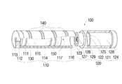
도 1은 본 발명의 제 1 실시예에 따른 기화 흡입 장치가 분리된 모습을 보이는 사시도이고, 도 2는 본 발명의 제 1 실시예에 따른 기화 흡입 장치가 결합된 모습을 보이는 사시도이다.1 is a perspective view showing the vaporized suction device according to the first embodiment of the present invention is separated, Figure 2 is a perspective view showing a combined state of the vaporization suction device according to the first embodiment of the present invention.
도 1 및 도 2를 함께 참조하면, 본 실시예에 따른 기화 흡입 장치(100)는 제 1 분할 부재(110)와, 제 2 분할 부재(120)를 포함하고, 사용자가 흡입할 수 있도록 내부에 수용된 기화 대상체를 흡입 대상 기체로 기화할 수 있는 것이다.1 and 2 together, the
여기서, 상기 기화 흡입 장치(100)가 상기 제 1 분할 부재(110)와 상기 제 2 분할 부재(120)로 구성되는 것으로 제시되나, 이는 예시적인 것이고, 상기 기화 흡입 장치(100)는 더 많은 개수의 분할 부재로 분할될 수도 있고, 그러한 복수 개의 분할 부재 내에 상기 기화 대상체를 상기 흡입 대상 기체로 기화시키기 위한 구성 요소들이 분할되어 수용될 수 있다.Here, the
상기 제 1 분할 부재(110)의 케이스(111) 내에는 발광 다이오드(113), 발광부(130), 배터리(115), 제어부(114) 및 흡입 감지 스위치(150)가 배치된다.The
상기 제 2 분할 부재(120)의 케이스(121) 내에는 발열 부재(125), 액체 수용 부재(126) 및 뚜껑(124)이 배치된다.The
여기서, 상기 제 1 분할 부재(110)의 케이스(111)는 전측 케이스로, 상기 제 2 분할 부재(120)의 케이스(121)는 후측 케이스로 정의될 수 있다.Here, the
본 실시예에서는 상기 제 1 분할 부재(110)의 케이스(111) 외면에 복수 개의 발광 부재(140)가 설치된다. 상기 복수 개의 발광 부재(140)는 서로 독립적으로 발광할 수 있는 것으로, 상기 제어부(114)의 제어 명령에 따라 미리 정해진 순서대로 발광할 수 있다.In the present embodiment, a plurality of
여기서, 상기 발광 부재(140)가 상기 케이스(111) 외면에 설치되는 것으로 제시되나, 이는 예시적인 것이고, 상기 케이스(111)의 내면에 설치되고, 투명한 커버로 덮이도록 구성될 수도 있다.Here, the
상기 복수 개의 발광 부재(140)로는 작동 효율이 우수한 발광 다이오드(LED, light emitting diode)가 제시될 수 있다.As the plurality of
여기서, 상기 발광 부재(140)가 상기 제 1 분할 부재(110)의 케이스(111) 외면에 설치되는 것으로 제시되나, 이는 예시적인 것이고, 상기 제 2 분할 부재(120)의 케이스(121)는 물론, 상기 제 1 분할 부재(110)의 케이스(111) 및 상기 제 2 분할 부재(120)의 케이스(121) 모두에 설치될 수도 있다.Here, the
또한, 상기 제 1 분할 부재(110)의 케이스(111)와 상기 제 2 분할 부재(120)의 케이스(121)는 내부에 상기 기화 대상체를 상기 흡입 대상 기체로 기화시키기 위한 구성 요소들이 수용되는 것으로, 기화 흡입 장치 몸체로 정의될 수 있다.In addition, the
상기 발광 다이오드(113)는 상기 배터리(115)에 전기적으로 연결되어, 붉은 색으로 발광할 수 있는 부분이다. 이러한 발광 다이오드(113)는 케이스(111) 전면의 전면 부재(112)에 형성된다. 상기 발광부(130)는 상기 발광 다이오드(113)와 연결되어, 상기 제어부(114)의 제어에 따라 상기 발광 다이오드(113)를 발광시킨다.The
상기 배터리(115)는 상기 발광 다이오드(113), 상기 제어부(114), 상기 발열 부재(125), 상기 발광 부재(140) 등에 전원을 인가하는 부분으로, 폴리머 리튬 전지 등이 제시될 수 있다.The
상기 제어부(114)는 상기 기화 흡입 장치(100)의 작동을 위해 요구되는 각종 회로가 형성된 부분이다. 이러한 제어부(114)는 상기 흡입 감지 스위치(150)에서 전달된 감지값에 따라 상기 발광 다이오드(113), 상기 발열 부재(125), 상기 발광 부재(140) 등의 작동을 제어할 수 있다.The
상기 케이스(111)의 후측 말단에는 부압 형성부(116)가 형성된다. 상기 부압 형성부(116)에는 외기 도입 홀(117)이 형성된다. 상기 외기 도입 홀(117)은 복수 개 형성될 수 있다. 상기 외기 도입 홀(117)은 외기 도입부로 정의될 수 있다.A negative
사용자가 흡입을 하면, 상기 부압 형성부(116) 내의 공기가 상기 제 2 분할 부재(120)를 통해 사용자의 입 속으로 유입되고, 그에 따라 상기 부압 형성부(116)에 부압(負壓)이 형성되고, 그에 따라 상기 외기 도입 홀(117)을 통해 외기가 상기 부압 형성부(116)로 유입된다.When the user inhales, air in the negative
사용자가 흡입 시에 상기 외기 도입 홀(117)을 통해 상기 부압 형성부(116)로 도입되는 외기는 상기 발열 부재(125)에 의해 기화된 흡입 대상 기체인 니코틴과 함께 사용자에게 흡입된다.When the user inhales, the outside air introduced into the negative
상기 흡입 감지 스위치(150)는 사용자가 상기 제 2 분할 부재(120)의 말단부를 입으로 물고 흡입을 할 때, 그러한 흡입 여부를 감지하는 부분이다.The
상기 흡입 감지 스위치(150)가 사용자의 흡입을 감지하면, 상기 제어부(114)는 상기 액체 수용 부재(126) 내의 액체가 기화되도록, 상기 발열 부재(125)를 작동시킨다.When the
상기 제 2 분할 부재(120)의 전측에는 삽입체(122)가 형성된다. 상기 삽입체(122)는 상기 부압 형성부(116)의 말단에 삽입된다. 상기 삽입체(122)가 상기 부압 형성부(116)에 삽입되더라도, 상기 외기 도입 홀(117)은 상기 삽입체(122)에 의해 가려지지 아니한다. 그리고, 상기 삽입체(122)는 상기 배터리(115) 및 상기 제어부(114)와 전기적으로 연결된다. 예를 들어, 상기 삽입체(122)의 외면과 상기 부압 형성부(116)의 내면에 서로 맞닿는 전극이 형성되고, 상기 삽입체(122)의 외면에 형성된 전극은 상기 발열 부재(125)와 전기적으로 연결되고, 상기 부압 형성부(116)의 내면에 형성된 전극은 상기 제어부(114) 및 상기 배터리(115)와 전기적으로 연결될 수 있다.An
상기 삽입체(122)의 중앙부에는 외기 유동 홀(123)이 형성된다. 상기 외기 유동 홀(123)을 통해 상기 부압 형성부(116) 내의 공기가 상기 제 2 분할 부재(120) 케이스(121) 내부로 유입될 수 있다. 상기와 같이 유입된 공기는 상기 발열 부재(125)를 거쳐 상기 뚜껑(124)에 형성된 흡입 홀(미도시)을 통해 사용자의 입으로 유출된다.The outside
상기 외기 유동 홀(123) 주변부(127)의 주변에는 함몰된 형태의 함몰부(128)가 형성되고, 상기 함몰부(128)의 주변에는 상기 삽입체(122)의 외곽부(129)가 형성된다.A recessed
상기 발열 부재(125)는 상기 제어부(114)의 명령에 따라 상기 배터리(115)로부터 전원을 공급받아 발열할 수 있는 부분이다. 상기 발열 부재(125)가 발열하면, 그 열에 의해 상기 액체 수용 부재(126)에서 전달된 니코틴 액이 기화될 수 있다. 상기 발열 부재(125)에 의해 기화된 니코틴은 상기 외기 유동 홀(123)을 통해 유입된 공기와 혼합되어, 상기 뚜껑(124)을 통해 사용자의 입으로 유출된다.The
상기 액체 수용 부재(126)는 내부에 니코틴 액이 액상으로 수용된 것으로, 그 내부에 수용된 니코틴 액을 상기 발열 부재(125)로 전달한다.The
본 실시예에서는, 상기 복수 개의 발광 부재(140)가 서로 이격되면서 상기 제 1 분할 부재(110)의 케이스(111) 외주면을 따라 띠 형상으로 배치된다.In the present exemplary embodiment, the plurality of light emitting
또한, 상기 흡입 감지 스위치(150)에 의해 사용자가 흡입하는 것으로 감지되면, 상기 제어부(114)의 명령에 따라 상기 복수 개의 발광 부재(140)가 미리 정해진 순서대로 발광한다.In addition, when it is detected that the user inhales by the
여기서, 상기 복수 개의 발광 부재(140)의 발광 순서는 전측에서 후측으로 순차적으로 발광하거나, 그 반대 방향으로 순차적으로 발광하거나, 순차적으로 점멸하거나, 임의 순서대로 발광하는 등 다양한 형식으로 제시될 수 있다.Here, the light emission order of the plurality of light emitting
상기와 같이 구성되면, 상기 흡입 감지 스위치(150)에 의해 사용자가 흡입하는 것으로 감지되면, 상기 복수 개의 발광 부재(140)가 미리 정해진 순서대로 작동, 즉 발광함에 따라, 상기 기화 흡입 장치(100)를 사용하는 사용자의 흥미를 유발할 수 있고, 상기 기화 흡입 장치(100)의 수려한 외관을 창출할 수 있다.When configured as described above, when the
이하에서는 상기와 같이 구성된 기화 흡입 장치(100)의 작동에 대하여 간단히 설명한다.Hereinafter, the operation of the
먼저, 사용자가 상기 기화 흡입 장치(100)를 입에 물고 흡입을 하면, 상기 흡입 감지 스위치(150)가 이를 감지하고, 상기 제어부(114)에 해당 감지값을 전달한다.First, when the user inhales the
상세히, 사용자가 흡입을 시작하면, 상기 제 2 분할 부재(120) 케이스(121) 내부의 공기가 사용자의 입 속으로 유출되고, 순차적으로 상기 부압 형성부(116) 내의 공기도 유출되어, 상기 부압 형성부(116) 내에 부압이 형성된다. 상기 외기 도입 홀(117)을 통해 소량의 공기가 지속적으로 유입됨으로써, 사용자의 흡입 과정 동안, 상기 부압 형성부(116) 내에 지속적으로 부압이 형성되도록 한다.In detail, when the user starts suction, air in the case of the
상기 부압 형성부(116) 내에 부압이 형성되면, 상기 흡입 감지 스위치(150)가 사용자의 흡입 여부를 감지하게 된다.When a negative pressure is formed in the negative
한편, 상기 감지값을 전달받은 상기 제어부(114)는 상기 발광 다이오드(113) 및 상기 발열 부재(125)에 구동 명령을 전달하고, 그에 따라 상기 발광 다이오드(113) 및 상기 발열 부재(125)는 상기 배터리(115)의 전원을 공급받아 각각 발광 및 발열을 하게 된다.On the other hand, the
상기 발열 부재(125)가 발열하면, 그 열에 의해 전달된 니코틴 액이 기화되어 연기가 형성된다. 상기와 같이 형성된 연기는 상기 제 2 분할 부재(120)의 뚜껑(124)을 통해 사용자의 입 내부로 유출된다.When the
상기와 같은 기화 흡입 장치(100)의 작동에 의해, 사용자는 실제 담배를 피우는 것과 유사한 느낌을 얻게 된다.By the operation of the
한편, 상기 사용자의 흡입에 대한 감지값을 전달받은 상기 제어부(114)가 상기 복수 개의 발광 부재(140)에 구동 명령을 전달하고, 그에 따라 상기 복수 개의 발광 부재(140)가 미리 정해진 순서대로 발광하면서, 사용자의 흥미를 유발할 수 있게 된다.On the other hand, the
이하에서는 도면을 참조하여 본 발명의 다른 실시예들에 대하여 설명한다. 이러한 설명을 수행함에 있어서 상기된 본 발명의 제 1 실시예에서 이미 기재된 내용과 중복되는 설명은 그에 갈음하고, 여기서는 생략하기로 한다.Hereinafter, other embodiments of the present invention will be described with reference to the accompanying drawings. In carrying out this description, the description overlapping with the contents already described in the above-described first embodiment of the present invention will be replaced with the description thereof, and will be omitted herein.
도 3은 본 발명의 제 2 실시예에 따른 기화 흡입 장치가 결합된 모습을 보이는 사시도이다.3 is a perspective view showing a state in which the vaporization suction device according to the second embodiment of the present invention is coupled.
도 3을 참조하면, 본 실시예에서는 상기 기화 흡입 장치(200)의 제 1 분할 부재의 케이스(211) 외주면에 복수 개의 발광 부재(240)가 서로 이격되면서 경사진 형태로 띠 형상으로 배치된다.Referring to FIG. 3, in the present exemplary embodiment, a plurality of light emitting
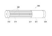
도 4는 본 발명의 제 3 실시예에 따른 기화 흡입 장치가 결합된 모습을 보이는 사시도이다.4 is a perspective view showing a state in which the vaporization suction device according to the third embodiment of the present invention is coupled.
도 4를 참조하면, 본 실시예에서는 상기 기화 흡입 장치(300)의 제 1 분할 부재의 케이스(311) 외주면에 복수 개의 발광 부재(340)가 서로 이격되면서 케이스(311)의 길이 방향을 따라 길게 배치된다.Referring to FIG. 4, in the present exemplary embodiment, the plurality of light emitting
도 5는 본 발명의 제 4 실시예에 따른 기화 흡입 장치가 결합된 모습을 보이는 사시도이다.5 is a perspective view showing a state in which the vaporization suction device according to the fourth embodiment of the present invention is coupled.
도 5를 참조하면, 본 실시예에서는 상기 기화 흡입 장치(400)의 제 1 분할 부재의 케이스(411) 외주면에 복수 개의 발광 부재(440)가 서로 이격되면서 상기 케이스(411)에 점 형상으로 배치된다.Referring to FIG. 5, in the present exemplary embodiment, a plurality of light emitting
상기와 같이 도 1 내지 도 5에서 제시된 형태 이외에도, 복수 개의 발광 부재의 다양한 배치 형태, 예를 들어 서로 이격되면서 기화 흡입 장치 몸체에 나사선 모양으로 배치되거나, 특정 무늬 모양으로 배치되는 등의 형태가 제시될 수 있고, 이러한 형태들도 본 발명의 범위에 포함됨을 밝혀 둔다.In addition to the forms shown in FIGS. 1 to 5 as described above, various arrangement forms of the plurality of light emitting members, for example, are disposed in a spiral shape or are arranged in a specific pattern shape on the vaporization suction device body while being spaced apart from each other. It is to be understood that such forms are included within the scope of the present invention.
도 6은 본 발명의 제 5 실시예에 따른 기화 흡입 장치가 분리된 모습을 보이는 사시도이다.6 is a perspective view showing a state in which the vaporization suction device according to the fifth embodiment of the present invention is separated.
도 6을 참조하면, 본 실시예에서는, 기화 흡입 장치(500)의 제 1 분할 부재(510)의 케이스(511) 내부에 기화 흡입 장치 몸체의 진동을 감지하는 진동 감지 센서(560)가 배치된다.Referring to FIG. 6, in the present embodiment, a
상기 진동 감지 센서(560)에 의해 상기 기화 흡입 장치 몸체의 진동이 감지되면, 제어부(514)의 명령에 따라, 복수 개의 발광 부재(540)가 미리 정해진 순서대로 발광할 수 있다.When the vibration of the vaporization suction device body is detected by the
상기와 같이 구성되면, 상기 기화 흡입 장치(500)가 흔들리는 경우 상기 복수 개의 발광 부재(540)가 발광할 수 있으므로, 사용자의 흡입이 감지되지 아니하더라도, 사용자의 흥미를 유발할 수 있다.When configured as described above, when the
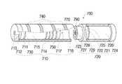
도 7은 본 발명의 제 6 실시예에 따른 기화 흡입 장치가 분리된 모습을 보이는 사시도이다.7 is a perspective view showing a state in which the vaporization suction device according to the sixth embodiment of the present invention is separated.
도 7을 참조하면, 본 실시예에서는, 기화 흡입 장치(600)의 제 1 분할 부재(610)의 케이스(611) 내부에 외부의 소리를 감지하는 음향 부재(670)가 배치된다.Referring to FIG. 7, in the present exemplary embodiment, an
상기 음향 부재(670)에 의해 외부의 소리가 감지되면, 복수 개의 발광 부재(640)가 미리 정해진 순서대로 발광한다.When external sound is detected by the
상기와 같이 구성되면, 상기 기화 흡입 장치(600) 외부에서 소리가 발생되는 경우 상기 복수 개의 발광 부재(640)가 발광할 수 있으므로, 사용자의 흡입이 감지되지 아니하더라도, 사용자의 흥미를 유발할 수 있다.When configured as described above, when a sound is generated outside the
또한, 상기 음향 부재(670)는 상기 감지되는 외부의 소리를 녹음할 수 있고, 그러한 녹음된 외부의 소리를 상기 복수 개의 발광 부재(640)의 발광과 함께 재생시킬 수 있다.In addition, the
또한, 상기 음향 부재(670)는 상기 녹음된 외부의 소리 이외에도 미리 설정된 음향 등 다양한 음향을 발생시킬 수 있고, 상기 복수 개의 발광 부재(640)의 발광과 함께 그러한 음향을 재생시킬 수 있다.In addition, the
또한, 상기 복수 개의 발광 부재(640)는 상기 음향 부재(670)에서 발생되는 음향에 따라 순서가 변하는 등 다양하게 발광될 수 있다.In addition, the plurality of light emitting
도 8은 본 발명의 제 7 실시예에 따른 기화 흡입 장치가 분리된 모습을 보이는 사시도이다.8 is a perspective view showing a state in which the vaporization suction device according to the seventh embodiment of the present invention is separated.
도 8을 참조하면, 본 실시예에서는, 기화 흡입 장치(700)의 제 1 분할 부재(710)의 케이스(711) 내부에 무선 전파를 송수신하면서, 다른 기화 흡입 장치가 일정 거리 범위 내로 근접되는지 여부를 감지하는 무선 전파 송수신 부재(780)가 배치된다. 상기 무선 전파 송수신 부재(780)는 상기 다른 기화 흡입 장치 내부에 설치된 무선 전파 송수신 부재와 무선 전파를 송수신할 수 있다.Referring to FIG. 8, in the present exemplary embodiment, whether other vaporization suction apparatuses are within a predetermined distance range while transmitting and receiving radio waves inside the
상기 무선 전파 송수신 부재(780)에 의해 상기 다른 기화 흡입 장치가 상기 기화 흡입 장치(700)를 기준으로 일정 거리 범위 내로 근접되는 것으로 감지되면, 복수 개의 발광 부재(740)가 미리 정해진 순서대로 발광한다.When it is detected by the radio wave transmitting and receiving
상기와 같이 구성되면, 상기 기화 흡입 장치(700)를 기준으로 일정 거리 범위 내로 상기 다른 기화 흡입 장치가 근접되는 경우 상기 복수 개의 발광 부재(740)가 발광할 수 있으므로, 사용자의 흡입이 감지되지 아니하더라도, 사용자의 흥미를 유발할 수 있고, 상기 기화 흡입 장치(700)를 소지한 사용자가 상기 다른 기화 흡입 장치를 소지한 다른 사용자를 용이하게 인지할 수 있다.When configured as described above, the plurality of light emitting
또한, 상기 무선 전파 송수신 부재(780)에 의해 상기 다른 기화 흡입 장치가 점차적으로 더 근접되는 것으로 감지되면, 상기 제어부(714)에 의해 상기 복수 개의 발광 부재(740)의 발광 주기가 상기 다른 기화 흡입 장치의 근접 정도에 따라 가변될 수 있다. 예를 들어, 상기 다른 기화 흡입 장치가 상기 기화 흡입 장치(700)로 근접될수록, 상기 복수 개의 발광 부재(740)의 발광 주기가 짧아지도록 제어될 수 있다.In addition, when it is detected by the radio wave transmitting and receiving
한편, 상기 기화 흡입 장치(700)는 상기 제 1 분할 부재(710)의 케이스(711) 내부에 음향을 발생시킬 수 있는 음향 부재(770)가 배치될 수 있다. 이러한 경우, 상기 무선 전파 송수신 부재(780)에 의해 상기 다른 기화 흡입 장치가 상기 기화 흡입 장치(700)를 기준으로 일정 거리 범위 내로 근접되는 것으로 감지되면, 상기 복수 개의 발광 부재(740)의 발광과 함께 상기 음향 부재(770)에서 미리 정해진 음향을 발생시킬 수 있으므로, 사용자의 흥미가 더욱 유발될 수 있다.On the other hand, the
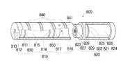
도 9는 본 발명의 제 8 실시예에 따른 기화 흡입 장치가 분리된 모습을 보이는 사시도이다.9 is a perspective view showing a state in which the vaporization suction device according to the eighth embodiment of the present invention is separated.
도 8을 참조하면, 본 실시예에서는, 기화 흡입 장치(800)의 제 1 분할 부재(810)의 케이스(811)에 복수 개의 발광 부재(840)가 배치되고, 상기 케이스(811) 외면에 사용자가 선택할 수 있는 선택 부재(841)가 형성된다.Referring to FIG. 8, in the present embodiment, a plurality of light emitting
상기 선택 부재(841)는 제어부(814)를 통해 간접적으로 상기 복수 개의 발광 부재(840)에 연결되거나, 또는 상기 복수 개의 발광 부재(840)에 직접적으로 연결되는 것으로, 상기 선택 부재(841)가 사용자에 의해 눌려지는 등의 방식으로 선택되면, 상기 복수 개의 발광 부재(840)가 발광하게 된다.The
상기와 같이 구성되면, 상기 선택 부재(841)가 사용자에 의해 선택되는 경우, 상기 복수 개의 발광 부재(840)가 작동할 수 있으므로, 사용자의 흡입이 감지되지 아니하더라도, 사용자의 흥미를 유발할 수 있다.When the
여기서, 상기 선택 부재(841)가 상기 제 1 분할 부재(810)의 케이스(811) 외면에 설치되는 것으로 제시되나, 이는 예시적인 것이고, 제 2 분할 부재(820)의 케이스(821) 등 다른 부분에 설치될 수도 있다.Here, the
도 10은 본 발명의 제 9 실시예에 따른 기화 흡입 장치가 결합된 모습을 보이는 사시도이다.10 is a perspective view showing a state in which the vaporization suction device according to the ninth embodiment of the present invention is coupled.
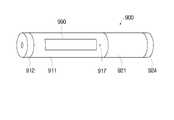
도 10을 참조하면, 본 실시예에 따른 기화 흡입 장치(900)의 몸체에 소정 정보를 표시할 수 있는 디스플레이 부재(990)가 배치된다. 상기 디스플레이 부재(990)는 각종 정보를 디지털 형식 등으로 표시할 수 있다.Referring to FIG. 10, a
이러한 기화 흡입 장치(900)에는 상기된 실시예들의 구성 및 그 작동 방식이 적용될 수 있다. 예를 들어, 상기 기화 흡입 장치(900)가 작동되거나, 진동 감지 센서를 구비하여 상기 진동 감지 센서에 의해 기화 흡입 장치 몸체의 진동이 감지되거나, 음향 부재를 구비하여 상기 음향 부재에 의해 외부의 소리가 감지되거나, 상기 감지되는 외부의 소리를 녹음하거나, 무선 전파 송수신 부재를 구비하여 상기 무선 전파 송수신 부재에 의해 상기 다른 기화 흡입 장치가 일정 거리 범위 내로 근접되는 것으로 감지되거나, 선택 부재를 구비하여 상기 선택 부재가 사용자에 의해 선택되는 등의 경우에 상기 디스플레이 부재(990)가 작동되어, 소정 정보를 표시할 수 있다.Such a
또한, 상기 디스플레이 부재(990)는 상기 음향 부재의 발생 음향에 따라 작동되거나, 상기 다른 기화 흡입 장치의 근접 정도에 따라 그 작동 주기가 가변되거나, 상기 무선 전파 송수신 부재에 의해 상기 다른 기화 흡입 장치가 일정 거리 범위 내로 근접되는 것으로 감지되는 경우 상기 음향 부재에서 음향을 발생시키는 것과 함께 작동되거나, 상기 다른 기화 흡입 장치와의 거리가 표시되는 등의 작동도 가능하다.In addition, the
물론, 상기된 복수 개의 발광 부재와 상기 디스플레이 부재가 함께 배치될 수도 있다.Of course, the plurality of light emitting members and the display member may be disposed together.
상기에서 본 발명은 특정한 실시예에 관하여 도시되고 설명되었지만, 당업계에서 통상의 지식을 가진 자라면 이하의 특허청구범위에 기재된 본 발명의 사상 및 영역을 벗어나지 않는 범위 내에서 본 발명을 다양하게 수정 및 변경시킬 수 있음을 알 수 있을 것이다. 그렇지만 이러한 수정 및 변형 구조들은 모두 본 발명의 권리범위 내에 포함되는 것임을 분명하게 밝혀두고자 한다.While the invention has been shown and described with respect to specific embodiments thereof, those skilled in the art can variously modify the invention without departing from the spirit and scope of the invention as set forth in the claims below. And that it can be changed. However, it is intended that the present invention covers the modifications and variations of this invention provided they come within the scope of the appended claims and their equivalents.
본 발명의 일 측면에 따른 기화 흡입 장치에 의하면, 사용자의 흥미를 유발할 수 있으므로, 그 산업상 이용 가능성이 높다고 하겠다.
According to the vaporization suction device according to an aspect of the present invention, since it can cause interest of the user, it is said that the industrial applicability is high.
Claims (13)
Translated fromKorean내부에 상기 기화 대상체를 상기 흡입 대상 기체로 기화시키기 위한 구성 요소들이 수용되는 기화 흡입 장치 몸체; 및
상기 기화 흡입 장치 몸체에 복수 개로 형성되어, 서로 독립적으로 발광할 수 있는 발광 부재;를 포함하는 기화 흡입 장치.A vaporization suction device capable of vaporizing a vaporization object accommodated therein for inhalation by a user to inhalation gas,
A vaporization suction device body accommodating therein components for vaporizing the vaporization object with the inhalation gas; And
And a plurality of light emitting members formed in the body of the vaporization suction apparatus and capable of emitting light independently of each other.
상기 복수 개의 발광 부재는 서로 이격되면서 상기 기화 흡입 장치 몸체 외주면을 따라 띠 형상으로 배치되거나, 서로 이격되면서 상기 기화 흡입 장치 몸체의 길이 방향을 따라 길게 배치되거나, 또는 서로 이격되면서 상기 기화 흡입 장치 몸체에 점 형상으로 배치되거나, 서로 이격되면서 상기 기화 흡입 장치 몸체에 나사선 모양으로 배치되거나, 특정 무늬 모양으로 배치되는 것을 특징으로 하는 기화 흡입 장치.The method of claim 1,
The plurality of light emitting members are spaced apart from each other and disposed in a strip shape along the outer circumferential surface of the vaporization suction device body, or are spaced apart from each other and elongated in the longitudinal direction of the vaporization suction device body or spaced apart from each other. The vaporization suction device, characterized in that arranged in a dot shape, spaced apart from each other in the shape of a screw thread on the body of the vaporization suction device, or a specific pattern.
내부에 상기 기화 대상체를 상기 흡입 대상 기체로 기화시키기 위한 구성 요소들이 수용되는 기화 흡입 장치 몸체; 및
상기 기화 흡입 장치 몸체에 형성되어, 소정 정보를 표시할 수 있는 디스플레이 부재;를 포함하는 기화 흡입 장치.A vaporization suction device capable of vaporizing a vaporization object accommodated therein for inhalation by a user to inhalation gas,
A vaporization suction device body accommodating therein components for vaporizing the vaporization object with the inhalation gas; And
And a display member formed on the vaporization suction device body and configured to display predetermined information.
상기 기화 흡입 장치가 작동되면, 상기 복수 개의 발광 부재 또는 상기 디스플레이 부재가 작동되는 것을 특징으로 하는 기화 흡입 장치.The method according to claim 1 or 3,
And when the vaporization suction device is operated, the plurality of light emitting members or the display member are operated.
상기 기화 흡입 장치는 상기 기화 흡입 장치 몸체의 진동을 감지하는 진동 감지 센서를 포함하고,
상기 진동 감지 센서에 의해 상기 기화 흡입 장치 몸체의 진동이 감지되면, 상기 복수 개의 발광 부재 또는 상기 디스플레이 부재가 작동되는 것을 특징으로 하는 기화 흡입 장치.The method according to claim 1 or 3,
The vaporization suction device includes a vibration detection sensor for detecting the vibration of the vaporization suction device body,
And when the vibration of the vaporization suction device body is detected by the vibration detection sensor, the plurality of light emitting members or the display member are operated.
상기 기화 흡입 장치는 외부의 소리를 감지하는 음향 부재를 포함하고,
상기 음향 부재에 의해 외부의 소리가 감지되면, 상기 복수 개의 발광 부재 또는 상기 디스플레이 부재가 작동되는 것을 특징으로 하는 기화 흡입 장치.The method according to claim 1 or 3,
The vaporization suction device includes an acoustic member for sensing an external sound,
And when the external sound is detected by the acoustic member, the plurality of light emitting members or the display members are operated.
상기 음향 부재는 외부의 소리를 감지하여, 상기 감지되는 외부의 소리를 녹음할 수 있는 것을 특징으로 하는 기화 흡입 장치.The method according to claim 1 or 3,
The acoustic member detects an external sound to record the detected external sound.
상기 음향 부재는 음향을 발생시킬 수 있고,
상기 음향 부재가 음향을 발생시키면, 상기 복수 개의 발광 부재 또는 상기 디스플레이 부재는 상기 음향 부재의 발생 음향에 따라 작동되는 것을 특징으로 하는 기화 흡입 장치.The method according to claim 6,
The acoustic member can generate sound,
And the light emitting member or the display member is operated in accordance with the generated sound of the acoustic member when the acoustic member generates sound.
상기 기화 흡입 장치는 무선 전파를 송수신하면서, 다른 기화 흡입 장치가 일정 거리 범위 내로 근접되는지 여부를 감지하는 무선 전파 송수신 부재를 포함하고,
상기 무선 전파 송수신 부재에 의해 상기 다른 기화 흡입 장치가 일정 거리 범위 내로 근접되는 것으로 감지되면, 상기 복수 개의 발광 부재 또는 상기 디스플레이 부재가 작동되는 것을 특징으로 하는 기화 흡입 장치.The method according to claim 1 or 3,
The vaporization suction device includes a radio wave transmission and reception member for transmitting and receiving radio waves, and detects whether another vaporization suction device is close to within a predetermined distance range,
And the plurality of light emitting members or the display member are activated when the other vaporization suction apparatus is detected to be approached within a predetermined distance range by the radio wave transmitting and receiving member.
상기 무선 전파 송수신 부재에 의해 상기 다른 기화 흡입 장치가 점차적으로 더 근접되는 것으로 감지되면, 상기 복수 개의 발광 부재 또는 상기 디스플레이 부재의 작동 주기가 상기 다른 기화 흡입 장치의 근접 정도에 따라 가변되는 것을 특징으로 하는 기화 흡입 장치.The method of claim 9,
And when the other vaporization suction device is gradually detected to be closer to each other by the radio wave transmitting and receiving member, an operation period of the plurality of light emitting members or the display member is changed according to the proximity of the other vaporization suction device. Vaporization suction device.
상기 기화 흡입 장치는 음향을 발생시킬 수 있는 음향 부재를 포함하고,
상기 무선 전파 송수신 부재에 의해 상기 다른 기화 흡입 장치가 일정 거리 범위 내로 근접되는 것으로 감지되면, 상기 복수 개의 발광 부재 또는 상기 디스플레이 부재의 작동과 함께 상기 음향 부재에서 음향을 발생시키는 것을 특징으로 하는 기화 흡입 장치.The method of claim 9,
The vaporization suction device includes an acoustic member capable of generating sound,
When the other vaporization suction device is detected by the radio wave transmitting and receiving member to be within a predetermined distance range, the vaporization suction, characterized in that for generating sound in the acoustic member with the operation of the plurality of light emitting member or the display member. Device.
상기 기화 흡입 장치는 무선 전파를 송수신하면서, 다른 기화 흡입 장치가 일정 거리 범위 내로 근접되는지 여부를 감지하는 무선 전파 송수신 부재를 포함하고,
상기 무선 전파 송수신 부재에 의해 상기 다른 기화 흡입 장치가 일정 거리 범위 내로 근접되는 것으로 감지되면, 상기 디스플레이 부재에 상기 다른 기화 흡입 장치와의 거리가 표시되는 것을 특징으로 하는 기화 흡입 장치.The method of claim 3, wherein
The vaporization suction device includes a radio wave transmission and reception member for transmitting and receiving radio waves, and detects whether another vaporization suction device is close to within a predetermined distance range,
And when the other vaporization suction device is detected to be approached within a predetermined distance range by the radio wave transmitting and receiving member, a distance from the other vaporization suction device is displayed on the display member.
상기 기화 흡입 장치 몸체에는 사용자가 선택하기 위한 선택 부재가 형성되고,
상기 선택 부재가 사용자에 의해 선택되면, 상기 복수 개의 발광 부재 또는 상기 디스플레이 부재가 작동되는 것을 특징으로 하는 기화 흡입 장치.
The method according to claim 1 or 3,
The vaporization suction device body is formed with a selection member for the user to select,
And the light emitting member or the display member is operated when the selection member is selected by a user.
Priority Applications (1)
| Application Number | Priority Date | Filing Date | Title |
|---|---|---|---|
| KR1020110053565AKR101269244B1 (en) | 2011-06-02 | 2011-06-02 | Vaporizing and inhaling apparatus |
Applications Claiming Priority (1)
| Application Number | Priority Date | Filing Date | Title |
|---|---|---|---|
| KR1020110053565AKR101269244B1 (en) | 2011-06-02 | 2011-06-02 | Vaporizing and inhaling apparatus |
Related Parent Applications (1)
| Application Number | Title | Priority Date | Filing Date |
|---|---|---|---|
| KR2020090013681UDivisionKR20110004156U (en) | 2009-06-02 | 2009-10-20 | Vaporizing and inhaling apparatus |
Related Child Applications (1)
| Application Number | Title | Priority Date | Filing Date |
|---|---|---|---|
| KR1020120010161ADivisionKR101269245B1 (en) | 2012-02-01 | 2012-02-01 | Vaporizing and inhaling apparatus |
Publications (2)
| Publication Number | Publication Date |
|---|---|
| KR20110079590Atrue KR20110079590A (en) | 2011-07-07 |
| KR101269244B1 KR101269244B1 (en) | 2013-06-04 |
Family
ID=44918902
Family Applications (1)
| Application Number | Title | Priority Date | Filing Date |
|---|---|---|---|
| KR1020110053565AExpired - Fee RelatedKR101269244B1 (en) | 2011-06-02 | 2011-06-02 | Vaporizing and inhaling apparatus |
Country Status (1)
| Country | Link |
|---|---|
| KR (1) | KR101269244B1 (en) |
Cited By (3)
| Publication number | Priority date | Publication date | Assignee | Title |
|---|---|---|---|---|
| CN103859609A (en)* | 2014-04-03 | 2014-06-18 | 刘秋明 | Electronic cigarette and electronic cigarette atomization control method |
| WO2015109620A1 (en)* | 2014-01-26 | 2015-07-30 | 吉瑞高新科技股份有限公司 | Electronic cigarette |
| CN105876864A (en)* | 2014-05-04 | 2016-08-24 | 惠州市吉瑞科技有限公司 | Electronic cigarette with voice control function and control method thereof |
Families Citing this family (1)
| Publication number | Priority date | Publication date | Assignee | Title |
|---|---|---|---|---|
| KR102135786B1 (en)* | 2018-06-20 | 2020-07-20 | 주식회사 이엠텍 | A fine particle generator |
Family Cites Families (2)
| Publication number | Priority date | Publication date | Assignee | Title |
|---|---|---|---|---|
| KR100469625B1 (en)* | 2002-07-26 | 2005-02-02 | 김제규 | Electornic cigar |
| CN100381083C (en)* | 2003-04-29 | 2008-04-16 | 韩力 | Non-combustible electronic spray cigarette |
- 2011
- 2011-06-02KRKR1020110053565Apatent/KR101269244B1/ennot_activeExpired - Fee Related
Cited By (5)
| Publication number | Priority date | Publication date | Assignee | Title |
|---|---|---|---|---|
| WO2015109620A1 (en)* | 2014-01-26 | 2015-07-30 | 吉瑞高新科技股份有限公司 | Electronic cigarette |
| CN103859609A (en)* | 2014-04-03 | 2014-06-18 | 刘秋明 | Electronic cigarette and electronic cigarette atomization control method |
| CN103859609B (en)* | 2014-04-03 | 2016-05-11 | 惠州市吉瑞科技有限公司 | Electronic cigarette and electronic cigarette atomizing control method |
| US9756878B2 (en) | 2014-04-03 | 2017-09-12 | Huizhou Kimree Technology Co., Ltd. Shenzhen Branch | Electronic cigarette and atomization control method thereof |
| CN105876864A (en)* | 2014-05-04 | 2016-08-24 | 惠州市吉瑞科技有限公司 | Electronic cigarette with voice control function and control method thereof |
Also Published As
| Publication number | Publication date |
|---|---|
| KR101269244B1 (en) | 2013-06-04 |
Similar Documents
| Publication | Publication Date | Title |
|---|---|---|
| JP6979431B2 (en) | Aerosol delivery device including pressure-based aerosol delivery mechanism | |
| KR101233985B1 (en) | Electronic cigarette Liquid vaporizing and inhaling type | |
| KR101165772B1 (en) | Liquid vaporizing and inhaling apparatus | |
| KR200470732Y1 (en) | Vaporizing and inhaling apparatus and vaporizing member applied the vaporizing and inhaling apparatus | |
| KR20120104964A (en) | Electronic cigarette liquid vaporizing and inhaling type | |
| KR101162688B1 (en) | Vaporizing and inhaling apparatus | |
| TW201143825A (en) | Personal vaporizing inhaler with internal light source | |
| KR20120103351A (en) | Vaporizing and inhaling apparatus and vaporizing member applied the vaporizing and inhaling apparatus | |
| KR20190143146A (en) | A fine particle generator | |
| KR101193644B1 (en) | Vaporizing and inhaling apparatus | |
| KR101250019B1 (en) | Inhaling apparatus and game providing member applied to the inhaling apparatus | |
| KR101269244B1 (en) | Vaporizing and inhaling apparatus | |
| KR20120034933A (en) | Electronic cigarette | |
| KR101184082B1 (en) | Vaporizing and inhaling apparatus | |
| KR20120025569A (en) | Vaporizing and inhaling apparatus | |
| KR101269245B1 (en) | Vaporizing and inhaling apparatus | |
| KR20110004156U (en) | Vaporizing and inhaling apparatus | |
| KR20100011034U (en) | Liquid vaporizing and inhaling apparatus | |
| KR20110003309U (en) | Vaporizing and inhaling apparatus | |
| KR20120090737A (en) | Inhaling apparatus and negative ion forming member applied the inhaling apparatus | |
| KR101275191B1 (en) | Inhaling apparatus and selecting member applied in the inhaling apparatus | |
| KR20110079591A (en) | Vaporization suction device | |
| KR101269246B1 (en) | Vaporizing and inhaling apparatus | |
| KR20130006877U (en) | Inhaling apparatus electricity supplying member case for the inhaling apparatus evaporating member case for the inhaling apparatus and inhaling material accommodating member case for the inhaling apparatus | |
| KR200479089Y1 (en) | Bundle type e-cigarette, case for bundle type e-cigarette and bundle type inhaling member for e-cigarette |
Legal Events
| Date | Code | Title | Description |
|---|---|---|---|
| A201 | Request for examination | ||
| PA0106 | Converted application | St.27 status event code:A-0-1-A10-A19-cnv-PA0106 St.27 status event code:A-0-1-A10-A21-cnv-PA0106 | |
| PA0201 | Request for examination | St.27 status event code:A-1-2-D10-D11-exm-PA0201 | |
| PG1501 | Laying open of application | St.27 status event code:A-1-1-Q10-Q12-nap-PG1501 | |
| PE0902 | Notice of grounds for rejection | St.27 status event code:A-1-2-D10-D21-exm-PE0902 | |
| T11-X000 | Administrative time limit extension requested | St.27 status event code:U-3-3-T10-T11-oth-X000 | |
| A107 | Divisional application of patent | ||
| E13-X000 | Pre-grant limitation requested | St.27 status event code:A-2-3-E10-E13-lim-X000 | |
| P11-X000 | Amendment of application requested | St.27 status event code:A-2-2-P10-P11-nap-X000 | |
| P13-X000 | Application amended | St.27 status event code:A-2-2-P10-P13-nap-X000 | |
| PA0107 | Divisional application | St.27 status event code:A-0-1-A10-A16-div-PA0107 St.27 status event code:A-0-1-A10-A18-div-PA0107 | |
| PE0902 | Notice of grounds for rejection | St.27 status event code:A-1-2-D10-D21-exm-PE0902 | |
| R18-X000 | Changes to party contact information recorded | St.27 status event code:A-3-3-R10-R18-oth-X000 | |
| T11-X000 | Administrative time limit extension requested | St.27 status event code:U-3-3-T10-T11-oth-X000 | |
| T11-X000 | Administrative time limit extension requested | St.27 status event code:U-3-3-T10-T11-oth-X000 | |
| R17-X000 | Change to representative recorded | St.27 status event code:A-3-3-R10-R17-oth-X000 | |
| E13-X000 | Pre-grant limitation requested | St.27 status event code:A-2-3-E10-E13-lim-X000 | |
| P11-X000 | Amendment of application requested | St.27 status event code:A-2-2-P10-P11-nap-X000 | |
| P13-X000 | Application amended | St.27 status event code:A-2-2-P10-P13-nap-X000 | |
| E701 | Decision to grant or registration of patent right | ||
| PE0701 | Decision of registration | St.27 status event code:A-1-2-D10-D22-exm-PE0701 | |
| R17-X000 | Change to representative recorded | St.27 status event code:A-3-3-R10-R17-oth-X000 | |
| PN2301 | Change of applicant | St.27 status event code:A-3-3-R10-R11-asn-PN2301 St.27 status event code:A-3-3-R10-R13-asn-PN2301 | |
| R17-X000 | Change to representative recorded | St.27 status event code:A-3-3-R10-R17-oth-X000 | |
| R18-X000 | Changes to party contact information recorded | St.27 status event code:A-3-3-R10-R18-oth-X000 | |
| GRNT | Written decision to grant | ||
| PR0701 | Registration of establishment | St.27 status event code:A-2-4-F10-F11-exm-PR0701 | |
| PR1002 | Payment of registration fee | Fee payment year number:1 St.27 status event code:A-2-2-U10-U11-oth-PR1002 | |
| PG1601 | Publication of registration | St.27 status event code:A-4-4-Q10-Q13-nap-PG1601 | |
| R18-X000 | Changes to party contact information recorded | St.27 status event code:A-5-5-R10-R18-oth-X000 | |
| FPAY | Annual fee payment | Payment date:20161123 Year of fee payment:4 | |
| PR1001 | Payment of annual fee | Fee payment year number:4 St.27 status event code:A-4-4-U10-U11-oth-PR1001 | |
| P22-X000 | Classification modified | St.27 status event code:A-4-4-P10-P22-nap-X000 | |
| FPAY | Annual fee payment | Payment date:20170522 Year of fee payment:5 | |
| PR1001 | Payment of annual fee | Fee payment year number:5 St.27 status event code:A-4-4-U10-U11-oth-PR1001 | |
| FPAY | Annual fee payment | Payment date:20180523 Year of fee payment:6 | |
| PR1001 | Payment of annual fee | Fee payment year number:6 St.27 status event code:A-4-4-U10-U11-oth-PR1001 | |
| P22-X000 | Classification modified | St.27 status event code:A-4-4-P10-P22-nap-X000 | |
| LAPS | Lapse due to unpaid annual fee | ||
| PC1903 | Unpaid annual fee | Not in force date:20190524 Payment event data comment text:Termination Category : DEFAULT_OF_REGISTRATION_FEE St.27 status event code:A-4-4-U10-U13-oth-PC1903 | |
| PC1903 | Unpaid annual fee | Ip right cessation event data comment text:Termination Category : DEFAULT_OF_REGISTRATION_FEE Not in force date:20190524 St.27 status event code:N-4-6-H10-H13-oth-PC1903 | |
| P22-X000 | Classification modified | St.27 status event code:A-4-4-P10-P22-nap-X000 |