KR20110073873A - Pattern roll and pattern forming apparatus using the same - Google Patents
Pattern roll and pattern forming apparatus using the sameDownload PDFInfo
- Publication number
- KR20110073873A KR20110073873AKR1020090130664AKR20090130664AKR20110073873AKR 20110073873 AKR20110073873 AKR 20110073873AKR 1020090130664 AKR1020090130664 AKR 1020090130664AKR 20090130664 AKR20090130664 AKR 20090130664AKR 20110073873 AKR20110073873 AKR 20110073873A
- Authority
- KR
- South Korea
- Prior art keywords
- pattern
- roll
- printing
- subpattern
- present
- Prior art date
- Legal status (The legal status is an assumption and is not a legal conclusion. Google has not performed a legal analysis and makes no representation as to the accuracy of the status listed.)
- Ceased
Links
- 238000007639printingMethods0.000claimsabstractdescription37
- 238000007645offset printingMethods0.000claimsabstractdescription14
- 239000002184metalSubstances0.000claimsabstractdescription6
- 238000000034methodMethods0.000claimsdescription20
- 239000000463materialSubstances0.000claimsdescription16
- 239000000758substrateSubstances0.000claimsdescription7
- 238000012546transferMethods0.000claimsdescription5
- 230000000694effectsEffects0.000abstractdescription2
- 238000002474experimental methodMethods0.000description3
- 230000007547defectEffects0.000description2
- 238000010586diagramMethods0.000description2
- 238000000206photolithographyMethods0.000description2
- 230000007261regionalizationEffects0.000description2
- 238000007650screen-printingMethods0.000description2
- 230000015572biosynthetic processEffects0.000description1
- 230000000052comparative effectEffects0.000description1
- 230000002950deficientEffects0.000description1
- 238000011161developmentMethods0.000description1
- 230000018109developmental processEffects0.000description1
- 238000007646gravure printingMethods0.000description1
- 238000010030laminatingMethods0.000description1
- 239000004973liquid crystal related substanceSubstances0.000description1
- 238000001465metallisationMethods0.000description1
- 238000012986modificationMethods0.000description1
- 230000004048modificationEffects0.000description1
- 229920002120photoresistant polymerPolymers0.000description1
- 229920001690polydopaminePolymers0.000description1
Images


Classifications
- B—PERFORMING OPERATIONS; TRANSPORTING
- B41—PRINTING; LINING MACHINES; TYPEWRITERS; STAMPS
- B41F—PRINTING MACHINES OR PRESSES
- B41F13/00—Common details of rotary presses or machines
- B41F13/08—Cylinders
- B41F13/10—Forme cylinders
- B41F13/11—Gravure cylinders
- B—PERFORMING OPERATIONS; TRANSPORTING
- B41—PRINTING; LINING MACHINES; TYPEWRITERS; STAMPS
- B41F—PRINTING MACHINES OR PRESSES
- B41F31/00—Inking arrangements or devices
- B41F31/26—Construction of inking rollers
- B—PERFORMING OPERATIONS; TRANSPORTING
- B41—PRINTING; LINING MACHINES; TYPEWRITERS; STAMPS
- B41F—PRINTING MACHINES OR PRESSES
- B41F9/00—Rotary intaglio printing presses
- B41F9/01—Rotary intaglio printing presses for indirect printing
- B—PERFORMING OPERATIONS; TRANSPORTING
- B41—PRINTING; LINING MACHINES; TYPEWRITERS; STAMPS
- B41F—PRINTING MACHINES OR PRESSES
- B41F9/00—Rotary intaglio printing presses
- B41F9/06—Details
- B41F9/08—Wiping mechanisms
- B41F9/10—Doctors, scrapers, or like devices
- G—PHYSICS
- G03—PHOTOGRAPHY; CINEMATOGRAPHY; ANALOGOUS TECHNIQUES USING WAVES OTHER THAN OPTICAL WAVES; ELECTROGRAPHY; HOLOGRAPHY
- G03F—PHOTOMECHANICAL PRODUCTION OF TEXTURED OR PATTERNED SURFACES, e.g. FOR PRINTING, FOR PROCESSING OF SEMICONDUCTOR DEVICES; MATERIALS THEREFOR; ORIGINALS THEREFOR; APPARATUS SPECIALLY ADAPTED THEREFOR
- G03F7/00—Photomechanical, e.g. photolithographic, production of textured or patterned surfaces, e.g. printing surfaces; Materials therefor, e.g. comprising photoresists; Apparatus specially adapted therefor
- G03F7/0002—Lithographic processes using patterning methods other than those involving the exposure to radiation, e.g. by stamping
Landscapes
- Engineering & Computer Science (AREA)
- Mechanical Engineering (AREA)
- Printing Methods (AREA)
- Physics & Mathematics (AREA)
- General Physics & Mathematics (AREA)
- Printing Plates And Materials Therefor (AREA)
Abstract
Translated fromKoreanDescription
Translated fromKorean본 발명은 그라비아 오프셋 인쇄에 사용되는 패턴롤 및 패턴형성장치에 관한 것이다.The present invention relates to a pattern roll and a pattern forming apparatus used for gravure offset printing.
근래, 핸드폰(mobile phone), PDA, 노트북 컴퓨터와 같은 각종 휴대용 전자기기가 발전함에 따라 이에 적용할 수 있는 경박단소용의 평판표시장치(Flat Panel Display)에 대한 요구가 점차 증대되고 있다. 이러한 평판표시장치로는 LCD(Liquid Crystal Display), PDP(Plasma Display Panel), FED(Field Emission Display), VFD(Vacuum Fluorescent Display) 등이 활발히 연구되고 있으며, 현재 그 실용화가 이루어지고 있다.Recently, with the development of various portable electronic devices such as mobile phones, PDAs, and notebook computers, there is an increasing demand for flat panel displays for light and thin applications. Such flat panel displays are being actively researched, such as liquid crystal displays (LCDs), plasma display panels (PDPs), field emission displays (FEDs), and vacuum fluorescent displays (VFDs).
이러한 다양한 디바이스 내부의 금속배선 패턴이나 LCD의 칼라필터 패턴을 형성하는 방법으로는 스크린 인쇄나 포토리소그라피 등의 다양한 패턴 형성방법을 이용하여 구현되고 있다. 그러나 스크린 인쇄는 그 패턴 형성의 정밀도가 떨어지는 단점이 있으며, 포토리소그라피 공정을 이용한 방법은 포토레지스트의 적층 및 노광, 현상공정을 수행하여야 하는 공정의 복잡성을 수반하며, 아울러 미세패턴의 형 성에는 한계가 드러나고 있다.As a method of forming the metallization pattern inside the various devices or the color filter pattern of the LCD, various pattern formation methods such as screen printing or photolithography are implemented. However, screen printing has a disadvantage in that the precision of the pattern formation is inferior, and the method using the photolithography process involves the complexity of the process of laminating, exposing and developing photoresist, and limiting the formation of fine patterns. Is revealed.
이러한 문제를 해결하기 위해 전사롤을 이용하여 기판상에 패턴을 인쇄하는 그라비아(gravure) 인쇄방법이 적용되고 있다.In order to solve this problem, a gravure printing method of printing a pattern on a substrate using a transfer roll has been applied.
도 1a를 참조하면, 이는 종래의 그라비아 오프셋 인쇄방법을 나타낸 개념도이다.Referring to Figure 1a, this is a conceptual diagram showing a conventional gravure offset printing method.
그라비아 오프셋 인쇄방법은 표면에 음각의 패턴이 형성된 패턴롤(10)에 인쇄재료(50)를 충진하기 위해 닥터나이프(Doctor Knife)를 이용하여 상기 패턴롤 상에 인쇄재료를 공급함과 동시에 상기 닥터나이프(40)를 이용하여 패턴 내부로 인쇄재료를 충진시킨다. 상기 닥터나이프(40)는 도시된 것처럼, 나이프(42)와 상기 나이프를 지지하는 홀더(41)로 이루어져 있으며, 상기 패턴롤의 면과 접촉하게 된다. 이후, 고무 등의 재질로 이루어진 블랑킷 롤(20)에 상기 패턴롤(10)에 형성된 패턴 형상이 전사되며, 상기 블랑킷 롤(20)에 전사된 패턴(21)을 다시 기판(30)에 인쇄하는 방식으로 구현된다.The gravure offset printing method supplies a printing material onto the pattern roll by using a doctor knife to fill the
그러나 상기의 닥터나이프를 통하여 인쇄재료를 충진하는 방식은, 패턴롤에 형성된 음각의 패턴 내부로 충진되는 인쇄재료의 양이 균일하게 충진되지 않아 인쇄불량이 발생하는 문제가 발생하였다. 특히, 상기 음각의 패턴을 고려할 때, 패턴롤의 회전방향(인쇄방향)과 동일한 방향(수평방향(a)의 패턴의 내부로는 인쇄재료가 고르게 충진되나, 패턴롤의 길이방향(수직방향(b)의 패턴의 내부로는 인쇄재료가 고르게 충진되지 않게 된다.However, in the method of filling the printing material through the doctor knife, the amount of printing material filled into the intaglio pattern formed on the pattern roll is not uniformly filled, causing a problem of printing defects. In particular, in consideration of the intaglio pattern, the printing material is evenly filled in the same direction as the rotation direction (printing direction) of the pattern roll (horizontal direction (a)), but the longitudinal direction (vertical direction ( The printing material is not evenly filled inside the pattern of b).
이는 도 1b에서 제시된 것과 같이, 인쇄재료(12)가 충진되는 패턴(11)이 상 술한 것처럼, 수직 및 수평방향의 형상을 구비하는 경우, 충진재료가 우선적으로 수평방향(a)의 패턴 내부를 따라 이동하여 수직방향(b)의 패턴으로 이동하면서 충진이 이루어지게 되는데, 상기 닥터나이프와 패턴롤이 선 접촉을 하며 인쇄재료를 충진하는 경우, 매우 미세한 패턴의 선 폭 때문에, 이 수평방향의 패턴 내부로 까지 충진될 만한 충분한 시간을 확보하지 못하여 충진 불량이 발생하게 된다.This is because, as shown in FIG. 1B, when the
도 1c를 참조하면, 상술한 종래의 패턴롤을 이용하여 그라비아 오프셋 방식으로 금속배선 패턴을 형성하는 경우 발생하는 또 다른 문제를 설명하기 위한 개념도이다.Referring to Figure 1c, it is a conceptual diagram for explaining another problem that occurs when forming a metal wiring pattern by the gravure offset method using the conventional pattern roll described above.
도시된 것처럼, 상술한 도 1a의 수직방향패턴의 인쇄불량 이외에도, 상기 패턴롤(20)의 표면에 형성되는 음각패턴(인쇄패턴; 21)이 일정 면적이상이 되는 경우에도 인쇄가 극히 불량(도 1c의 'b'참조)하게 되는 문제가 더불어 발생하게 된다. 특히, 상술한 음각패턴의 면적이 120*120㎛ 이상이 되는 경우, 도시된 것과 같이 수직패턴뿐만 아니라, 수평 패턴에서도 인쇄불량이 발생하게 된다.As shown, in addition to the printing failure of the vertical pattern of FIG. 1A described above, printing is extremely poor even when the intaglio pattern (print pattern) 21 formed on the surface of the
본 발명은 상술한 과제를 해결하기 위하여 안출된 것으로, 본 발명의 목적은 그라비아 오프셋 인쇄에 사용되는 패턴롤의 음각 패턴에 서브패턴을 구비할 있도록 하여, 일정 면적 이상에서 발생하는 인쇄성을 향상시킬 수 있으며, 특히 인쇄방향과 수평방향으로 형성되는 패턴의 인쇄성을 향상시킬 수 있는 패턴롤 및 이를 포함하는 패텬 형성장치를 제공하는 데 있다.SUMMARY OF THE INVENTION The present invention has been made to solve the above problems, and an object of the present invention is to provide a subpattern in an intaglio pattern of a pattern roll used for gravure offset printing, thereby improving printability occurring in a predetermined area or more. In particular, the present invention provides a pattern roll and a pattern forming apparatus including the same, which can improve printability of a pattern formed in a printing direction and a horizontal direction.
본 발명은 상술한 과제를 해결하기 위하여 안출된 것으로, 본 발명의 구성은 그라비아 오프셋 인쇄로 금속배선패턴을 형성하는 패턴롤에 있어서, 상기 패턴롤은 인쇄패턴에 대응되는 음각패턴을 구비하며, 상기 음각패턴은 적어도 1 이상의 서브패턴을 포함하여 이루어지는 것을 특징으로 하는 패턴롤을 제공할 수 있도록 한다.The present invention has been made to solve the above-described problems, the configuration of the present invention is a pattern roll for forming a metal wiring pattern by gravure offset printing, the pattern roll has a negative pattern corresponding to the printing pattern, The intaglio pattern may provide a pattern roll, which comprises at least one subpattern.
특히, 상술한 상기 서브패턴을 구비하는 음각패턴은 120㎛*120㎛ 이상의 단위면적을 구비하는 패턴에 형성할 수 있으며, 이 경우 상기 서브패턴은 (60~120)㎛*(60~120)㎛의 단위면적을 구비하는 것을 적어도 1 이상 형성할 수 있다.In particular, the intaglio pattern having the above-described subpattern may be formed in a pattern having a unit area of 120 μm * 120 μm or more, in which case the subpattern is (60-120) μm * (60-120) μm At least one having a unit area of can be formed.
아울러, 상술한 본 발명에서의 상기 서브패턴의 깊이는 1~100㎛로 형성할 수 있으며, 상기 서브패턴 간의 이격간격은 1~30㎛로 형성할 수 있다.In addition, the depth of the subpattern in the present invention described above may be formed to 1 ~ 100㎛, the spacing interval between the subpattern may be formed to 1 ~ 30㎛.
특히, 본 발명에 따른 상기 서브패턴은 패턴롤의 길이방향으로 형성되는 수직패턴에 형성될 수 있다.In particular, the subpattern according to the present invention may be formed in a vertical pattern formed in the longitudinal direction of the pattern roll.
본 발명은, 상술한 본 발명에 따른 그라비아 오프셋 인쇄용 패턴롤을 이용하 여 패턴 형성장치를 구성할 수 있으며 이는 다음과 같은 구성으로 형성될 수 있다.The present invention can be configured by using a pattern roll for gravure offset printing according to the present invention described above, which can be formed in the following configuration.
구체적으로는, 그라비아 오프셋 인쇄법을 이용하는 패턴 형성장치에 있어서, 인쇄패턴에 대응되는 음각 패턴을 포함하는 패턴롤; 을 포함하며, 상기 패턴롤에 접촉하여 패턴에 인쇄재료를 충진하는 닥터나이프; 상기 패턴롤의 패턴을 전사 받아 기판에 인쇄하는 전사롤; 을 더 포함하여 구현할 수 있다.Specifically, a pattern forming apparatus using a gravure offset printing method, comprising: a pattern roll including an intaglio pattern corresponding to a printed pattern; And a doctor knife contacting the pattern roll to fill a printing material in the pattern; A transfer roll which receives the pattern of the pattern roll and transfers the pattern onto a substrate; It can be implemented to include more.
상술한 패턴형성장치에 사용되는 상기 인쇄재료는 2000~20000cps의 점도를 구비하는 것을 이용할 수 있으며, 이를 통해 터치윈도우 등에 금속 패턴전극을 형성할 수 있다.The printing material used in the pattern forming apparatus described above may use a viscosity of 2000 to 20000 cps, and through this, a metal pattern electrode may be formed on a touch window or the like.
본 발명에 따르면, 그라비아 오프셋 인쇄에 사용되는 패턴롤의 음각 패턴에 서브패턴을 구비할 있도록 하여, 일정 면적 이상에서 발생하는 인쇄성을 향상시킬 수 있으며, 특히 인쇄방향과 수평방향으로 형성되는 패턴의 인쇄성을 향상시킬 수 있는 효과가 있다.According to the present invention, by providing a sub-pattern in the intaglio pattern of the pattern roll used for gravure offset printing, it is possible to improve the printability occurring in a predetermined area or more, in particular of the pattern formed in the printing direction and the horizontal direction There is an effect that can improve the printability.
이하에서는 첨부한 도면을 참조하여 본 발명에 따른 구성 및 작용을 구체적으로 설명한다. 첨부 도면을 참조하여 설명함에 있어, 도면 부호에 관계없이 동일한 구성요소는 동일한 참조부여를 부여하고, 이에 대한 중복설명은 생략하기로 한다. 제1, 제2 등의 용어는 다양한 구성요소들을 설명하는데 사용될 수 있지만, 상기 구성요소들은 상기 용어들에 의해 한정되어서는 안 된다. 상기 용어들은 하나의 구성요소를 다른 구성요소로부터 구별하는 목적으로만 사용된다.Hereinafter, with reference to the accompanying drawings will be described in detail the configuration and operation according to the present invention. In the description with reference to the accompanying drawings, the same components are given the same reference numerals regardless of the reference numerals, and duplicate description thereof will be omitted. The terms first, second, etc. may be used to describe various components, but the components should not be limited by the terms. The terms are used only for the purpose of distinguishing one component from another.
도 2a를 참조하면, 이는 종래의 패턴롤에 형성되는 음각패턴과 본 발명에 따른 서브패턴을 구현한 구조를 도시한 도면 및 이미지이다.Referring to FIG. 2A, this is a drawing and image showing a structure in which an intaglio pattern formed on a conventional pattern roll and a subpattern according to the present invention are implemented.
(a)에 도시된 것처럼, 종래의 패턴롤(120)의 표면에는 음각의 패턴(121)을 구현할 수 있으며, 상술한 바처럼, 이 패턴의 면적이 일정이상 크게 되면, 인쇄가 극히 불량하게 된다.As shown in (a), the
(b)에 도시된 것처럼, 본 발명에서는 패턴의 면적이 일정이상 되는 경우, 서브패턴(130)을 적어도 1 이상 형성하여 인쇄품질을 향상할 수 있도록 한다. 특히 구체적으로는 본 발명에서 패턴롤에 형성되는 음각패턴의 면적이 120㎛*120㎛ 이상이 되는 경우에는 인쇄가 현저히 불량하게 되는바, 이 이상의 면적으로 형성되는 음각패턴에는 (60~120)㎛*(60~120)㎛ 의 단위면적을 가지는 서브패턴을 적어도 1 이상 형성하여 인쇄품질의 향상을 도모할 수 있도록 함이 바람직하다. 물론 이는 단위면적을 고려한 것으로, 본 실시예에서는 단면이 정사각형 또는 직사각형인 음각패턴과 서브패턴을 고려한 것이나, 반드시 이에 한정되는 것은 아니며, 상술한 기준의 일정면적이상에는 서브패턴을 적용하는 것은 본 발명의 요지에 포함됨은 자명하다 할 것이다.As shown in (b), in the present invention, when the area of the pattern becomes more than a certain level, at least one or
특히, 본 발명에서 적용하는 서브패턴의 깊이(T2)는 1~100㎛로 형성할 수 있으며, 나아가 각 서브패턴 간의 간격(T1)은 1~30㎛의 범위로 형성할 수 있다. 이는 이 이상의 범위에서는 서브패턴을 형성하는 경우에도 인쇄가 극히 불량해지기 때문이다.In particular, the depth T2 of the subpattern applied in the present invention may be formed in a range of 1 to 100 μm, and the interval T1 between each subpattern may be formed in a range of 1 to 30 μm. This is because printing becomes extremely poor even when the subpattern is formed in the above range.
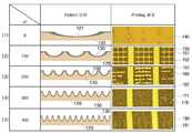
도 2b는 상술한 본 발명에 따른 바람직한 실시예에 따른 서브패턴의 구현시 인쇄품질의 결과를 비교한 표이다.Figure 2b is a table comparing the results of the print quality in the implementation of the sub-pattern according to the preferred embodiment according to the present invention described above.
본 실험에서는 1인치에 들어가는 서브패턴 라인의 개수(LPI;Line per inch)를 고려하여, 일정면적이상의 음각패턴에 들어가는 서브패턴에 따른 인쇄품질을 비교하였다. (본 비교 실험은 음각패턴의 면적이 500*500㎛에서 서브패턴의 수만을 변경한 것을 기준으로 비교한 것이다.)In this experiment, the print quality was compared according to the subpatterns in the intaglio pattern having a certain area in consideration of the number of lines per inch (LPI). (This comparison experiment is based on changing only the number of subpatterns when the area of the intaglio pattern is 500 * 500㎛.)
서브패턴을 형성하지 않은 경우(LPI=0)로 패턴롤(120)의 표면상에 음각패턴(121)을 하나로 형성한 후 그라비아 오프셋 방식으로 인쇄한 결과, 인쇄(printing) 결과는 인쇄패턴이 전혀 인쇄되지 않은 기판(140)의 표면만 나타나는 것을 확인할 수 있다.When the subpattern is not formed (LPI = 0), the
LPI가 "100"으로 보조패턴(130)을 다수 형성하는 경우, 인쇄결과를 참조하면, 미세한 미인쇄영역(151)이 나타나기는 하나, 인쇄영역(150)이 선명하게 인쇄되며, 극미세영역에서는 이러한 미인쇄영역은 무시할 수 있을 정도인바, 제품으로 사용할 수 있는 오차에 해당하게 된다.When the LPI forms a large number of
LPI가 각각 "200", "300", "400"인 경우에도, 미인쇄영역(161,162,171,181)이 나타나나, 선명한 인쇄영역(160, 170, 180)을 확인할 수 있으며, 이러한 오차는 상술한 바와 같이 제품으로서의 사용에 전혀 문제가 없을 정도의 오차에 해당하게 된다.Even when the LPI is "200", "300", or "400", the
즉, 일정 대면적의 음각패턴 내에 서브 패턴을 형성하게 되면, 이처럼 인쇄가 전혀 일어나지 않던 종래의 문제를 해소하여, 현저하게 향상된 인쇄품질을 구현 할 수 있게 된다.That is, when the sub-pattern is formed in the intaglio pattern of a certain large area, the conventional problem in which printing does not occur at all can be solved, and a markedly improved print quality can be realized.
도 2c는 본 발명에 따른 서브패턴을 구현하는 다른 일례를 도시한 것이다.2C illustrates another example of implementing a subpattern according to the present invention.
도시된 것처럼, 패턴 폭 120㎛인 음각패턴(210) 내에 60*60㎛의 서브패턴(220)을 형성한 경우, 인쇄결과를 살펴보면, 서브패턴이 없는 경우에는 인쇄가 현저하게 불량인 상태로 나타나나, 서브패턴이 있는 본 발명의 경우에는 선명한 인쇄영역(230)과 음각패턴이 없는 영역(213)의 경계가 명확하게 구분되어, 인쇄품질이 현저하게 향상된 것을 확인할 수 있다.As shown, in the case where the
아울러, 패턴폭 720㎛인 음각패턴(240) 경우, 60*60㎛ 서브패턴(250)을 다수 배치하는 경우, 서브패턴이 없는 경우에는 전혀 인쇄가 되지 않는 것(260; 인쇄가 될 기판만 나타남)을 확인할 수 있으며, 본원발명의 경우, 인쇄된 영역(270)이 선명하게 인쇄된 상태로 나타나며, 그 외 패턴이 없는 영역(271)과의 구분의 경계가 명확하게 구분되는 것을 확인할 수 있다.In addition, in the case of the
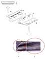
도 3은 본 발명에 따른 패턴형성장치의 실제 구현 예를 도시한 이미지와 이를 통해 인쇄되는 패턴 이미지를 도시한 것이다.Figure 3 shows an image showing an actual implementation of the pattern forming apparatus according to the present invention and a pattern image printed through it.
도시된 것처럼, 패턴롤(100)과 접촉하는 닥터나이프는 나이프(220)와 상기 나이프를 지지하는 지그부(210)를 포함하여 형성되며, 상기 패턴롤 면에는 도시된 것처럼 다양한 수직 및 수평패턴을 포함하는 음극의 패턴이 형성되며, 이후에는 기판에 전사를 하게 된다. 이 경우 상술한 수직패턴 또는 수평패턴에 본 발명에 따른 서브패턴을 구비하여 인쇄를 하는 경우, 종래 수직패턴에 의해 인쇄된 부분(b)의 인쇄가 도 1a과 비교할 때, 현저하게 우수한 인쇄가 이루어진 것을 확인할 수 있 다. 본 발명에 따른 패턴 형성장치에 사용되는 상기 인쇄재료는 2000~20000cps의 점도를 구비하는 것을 사용함이 바람직하다.As shown, the doctor knife is in contact with the
전술한 바와 같은 본 발명의 상세한 설명에서는 구체적인 실시예에 관해 설명하였다. 그러나 본 발명의 범주에서 벗어나지 않는 한도 내에서는 여러 가지 변형이 가능하다. 본 발명의 기술적 사상은 본 발명의 기술한 실시예에 국한되어 정해져서는 안 되며, 특허청구범위뿐만 아니라 이 특허청구범위와 균등한 것들에 의해 정해져야 한다.In the foregoing detailed description of the present invention, specific examples have been described. However, various modifications are possible within the scope of the present invention. The technical idea of the present invention should not be limited to the embodiments of the present invention but should be determined by the equivalents of the claims and the claims.
도 1a 내지 도 1c는 종래기술에 따른 그라비아 오프셋 인쇄방식과 이에 따른 문제점을 설명하기 위해 도시한 개념도이다.1A to 1C are conceptual views illustrating a gravure offset printing method and a problem according to the prior art.
도 2a 내지 도 2c는 본 발명에 따른 서브패턴을 구비한 패턴롤의 구현 실시예 및 종래기술과의 비교실험례를 도시한 것이다.2a to 2c illustrate an embodiment of a pattern roll having a sub-pattern according to the present invention and a comparative experiment example with the prior art.
도 3은 본 발명에 따른 패턴롤을 구비한 패턴형성장치를 도시한 것이다.3 illustrates a pattern forming apparatus having a pattern roll according to the present invention.
Claims (9)
Translated fromKoreanPriority Applications (3)
| Application Number | Priority Date | Filing Date | Title |
|---|---|---|---|
| KR1020090130664AKR20110073873A (en) | 2009-12-24 | 2009-12-24 | Pattern roll and pattern forming apparatus using the same |
| TW99145816ATW201139158A (en) | 2009-12-24 | 2010-12-24 | Pattern-roll and printing device including the same |
| PCT/KR2010/009334WO2011078627A2 (en) | 2009-12-24 | 2010-12-24 | Pattern-roll and printing device including the same |
Applications Claiming Priority (1)
| Application Number | Priority Date | Filing Date | Title |
|---|---|---|---|
| KR1020090130664AKR20110073873A (en) | 2009-12-24 | 2009-12-24 | Pattern roll and pattern forming apparatus using the same |
Publications (1)
| Publication Number | Publication Date |
|---|---|
| KR20110073873Atrue KR20110073873A (en) | 2011-06-30 |
Family
ID=44196352
Family Applications (1)
| Application Number | Title | Priority Date | Filing Date |
|---|---|---|---|
| KR1020090130664ACeasedKR20110073873A (en) | 2009-12-24 | 2009-12-24 | Pattern roll and pattern forming apparatus using the same |
Country Status (3)
| Country | Link |
|---|---|
| KR (1) | KR20110073873A (en) |
| TW (1) | TW201139158A (en) |
| WO (1) | WO2011078627A2 (en) |
Families Citing this family (1)
| Publication number | Priority date | Publication date | Assignee | Title |
|---|---|---|---|---|
| CN114571088A (en)* | 2022-02-28 | 2022-06-03 | 华鼎国联四川动力电池有限公司 | Micro-concave roller gap carving process |
Family Cites Families (8)
| Publication number | Priority date | Publication date | Assignee | Title |
|---|---|---|---|---|
| US6303184B1 (en)* | 1999-05-14 | 2001-10-16 | Eastman Kodak Company | Method of forming a discontinuous polymer overcoat for imaging elements |
| US20030138570A1 (en)* | 2001-12-21 | 2003-07-24 | Kimberly-Clark Worldwide, Inc. | Method to prepare diagnostic films using engraved printing cylinders such as rotogravure |
| KR100937613B1 (en)* | 2002-12-16 | 2010-01-20 | 이 잉크 코포레이션 | Backplanes for Electro-Optical Displays |
| EP1908599A1 (en)* | 2005-07-25 | 2008-04-09 | Think Laboratory Co., Ltd. | Gravure platemaking roll and process for producing the same |
| KR100839455B1 (en)* | 2006-11-03 | 2008-06-19 | 주식회사 에스에프에이 | printer |
| KR100942675B1 (en)* | 2006-10-20 | 2010-02-17 | 주식회사 엘지화학 | Two-layered structure sheet with excellent hard roll printability and its manufacturing method |
| CN101557927B (en)* | 2006-12-27 | 2014-10-22 | 日立化成株式会社 | Gravure plate and base material with conductor layer pattern using the same |
| KR100830094B1 (en)* | 2007-06-21 | 2008-05-16 | 주식회사 나래나노텍 | Printing roll apparatus for pattern formation and printing apparatus provided with the same |
- 2009
- 2009-12-24KRKR1020090130664Apatent/KR20110073873A/ennot_activeCeased
- 2010
- 2010-12-24TWTW99145816Apatent/TW201139158A/enunknown
- 2010-12-24WOPCT/KR2010/009334patent/WO2011078627A2/enactiveApplication Filing
Also Published As
| Publication number | Publication date |
|---|---|
| WO2011078627A3 (en) | 2011-11-10 |
| TW201139158A (en) | 2011-11-16 |
| WO2011078627A2 (en) | 2011-06-30 |
Similar Documents
| Publication | Publication Date | Title |
|---|---|---|
| KR101611379B1 (en) | Polarizer capacitive touch screen | |
| CN104520113B (en) | Gravure offset printing method, gravure offset printing device, and gravure | |
| CN102087472B (en) | Method for fabricating cliche and method for forming thin film pattern by using the same | |
| WO2014200238A1 (en) | Silk screen printing method for achieving printed bezel coating thickness required to improve defect rate in manufacture of touch screen panel | |
| US6853001B2 (en) | Electrode substrate of plasma display panel and method for making the same | |
| CN102165852B (en) | Pad printing plate for offset printing and products prepared using the pad printing plate | |
| KR101291878B1 (en) | Roller apparatus, printing method and method of fabricating liquid crystal display device using the same | |
| US9040149B2 (en) | Printing plate and method for manufacturing same | |
| CN102248756B (en) | Printing system, printing screen plate and printing template contained in printing system, and printing method of printing screen plate and printing template | |
| CN103465658A (en) | Printing method and printing apparatus | |
| KR20110073873A (en) | Pattern roll and pattern forming apparatus using the same | |
| CN104054157A (en) | Printing plate for reverse offset printing and its preparation method | |
| WO2012124950A2 (en) | Pattern roll, method for pattern forming and printing apparatus comprising the same | |
| JP2008258249A (en) | Pattern formation method, pattern forming apparatus and substrate for indicating device | |
| JP2006346915A (en) | Screen printing machine scraper | |
| JP2014128924A (en) | Gravure offset printing method | |
| KR101120060B1 (en) | Align System and Method of Stage, and A Pattern Forming Apparatus Having the Same | |
| KR20110071883A (en) | Pattern roll, pattern forming apparatus using the same, and metal wiring pattern | |
| KR20110071882A (en) | Pattern Forming Device | |
| JP6079232B2 (en) | Gravure offset printing method | |
| JP2014128925A (en) | Gravure offset printing method | |
| KR100839455B1 (en) | printer | |
| KR20140014786A (en) | Printing apparatus, system, and method for forming pattern on substrate | |
| KR20120135734A (en) | Apparatus for pattern formation and method for pattern formation | |
| KR20130025177A (en) | Printing apparatus |
Legal Events
| Date | Code | Title | Description |
|---|---|---|---|
| PA0109 | Patent application | Patent event code:PA01091R01D Comment text:Patent Application Patent event date:20091224 | |
| PG1501 | Laying open of application | ||
| A201 | Request for examination | ||
| PA0201 | Request for examination | Patent event code:PA02012R01D Patent event date:20140210 Comment text:Request for Examination of Application Patent event code:PA02011R01I Patent event date:20091224 Comment text:Patent Application | |
| E902 | Notification of reason for refusal | ||
| PE0902 | Notice of grounds for rejection | Comment text:Notification of reason for refusal Patent event date:20150623 Patent event code:PE09021S01D | |
| E601 | Decision to refuse application | ||
| PE0601 | Decision on rejection of patent | Patent event date:20150911 Comment text:Decision to Refuse Application Patent event code:PE06012S01D Patent event date:20150623 Comment text:Notification of reason for refusal Patent event code:PE06011S01I |