KR20110061246A - Integrated remote control and set top box - Google Patents
Integrated remote control and set top boxDownload PDFInfo
- Publication number
- KR20110061246A KR20110061246AKR1020090117839AKR20090117839AKR20110061246AKR 20110061246 AKR20110061246 AKR 20110061246AKR 1020090117839 AKR1020090117839 AKR 1020090117839AKR 20090117839 AKR20090117839 AKR 20090117839AKR 20110061246 AKR20110061246 AKR 20110061246A
- Authority
- KR
- South Korea
- Prior art keywords
- remote control
- top box
- signal
- mapping table
- button
- Prior art date
- Legal status (The legal status is an assumption and is not a legal conclusion. Google has not performed a legal analysis and makes no representation as to the accuracy of the status listed.)
- Ceased
Links
- 238000013507mappingMethods0.000claimsabstractdescription89
- 238000003860storageMethods0.000claimsabstractdescription11
- 238000000034methodMethods0.000claimsdescription15
- 230000008054signal transmissionEffects0.000abstractdescription4
- 238000010586diagramMethods0.000description3
- 238000007599dischargingMethods0.000description1
- 239000004973liquid crystal related substanceSubstances0.000description1
- 238000004519manufacturing processMethods0.000description1
- 238000003825pressingMethods0.000description1
Images


Classifications
- H—ELECTRICITY
- H04—ELECTRIC COMMUNICATION TECHNIQUE
- H04Q—SELECTING
- H04Q9/00—Arrangements in telecontrol or telemetry systems for selectively calling a substation from a main station, in which substation desired apparatus is selected for applying a control signal thereto or for obtaining measured values therefrom
- H04Q9/04—Arrangements for synchronous operation
- H—ELECTRICITY
- H04—ELECTRIC COMMUNICATION TECHNIQUE
- H04N—PICTORIAL COMMUNICATION, e.g. TELEVISION
- H04N21/00—Selective content distribution, e.g. interactive television or video on demand [VOD]
- H04N21/40—Client devices specifically adapted for the reception of or interaction with content, e.g. set-top-box [STB]; Operations thereof
- H04N21/41—Structure of client; Structure of client peripherals
- H04N21/422—Input-only peripherals, i.e. input devices connected to specially adapted client devices, e.g. global positioning system [GPS]
- H04N21/42204—User interfaces specially adapted for controlling a client device through a remote control device; Remote control devices therefor
- H—ELECTRICITY
- H04—ELECTRIC COMMUNICATION TECHNIQUE
- H04Q—SELECTING
- H04Q2209/00—Arrangements in telecontrol or telemetry systems
- H04Q2209/40—Arrangements in telecontrol or telemetry systems using a wireless architecture
Landscapes
- Engineering & Computer Science (AREA)
- Human Computer Interaction (AREA)
- Multimedia (AREA)
- Signal Processing (AREA)
- Computer Networks & Wireless Communication (AREA)
- Selective Calling Equipment (AREA)
- Details Of Television Systems (AREA)
Abstract
Translated fromKorean
Description
Translated fromKorean본 발명은 TV 및 셋탑박스를 함께 제어할 수 있는 통합리모컨 및 이러한 통합리모컨을 구비한 셋탑박스에 관한 것으로, 구체적으로는 TV 및 셋탑박스의 전원을 함께 온 또는 오프 할 수 있는 통합리모컨 및 이러한 통합리모컨을 구비한 셋탑박스에 관한 것이다.The present invention relates to an integrated remote control capable of controlling a TV and a set-top box, and a set-top box having such an integrated remote control. Specifically, the integrated remote control and the integrated remote control that can power on or off the TV and the set-top box together It relates to a set-top box having a remote control.
셋탑박스(set-top box, STB)는 TV에 연결되어, 외부에서 들어오는 신호를 받아 적절히 이를 변환하여 그 내용을 TV화면에 표시해 주는 장치이다. 셋탑박스는 일반 TV 방송용 전파가 아닌 신호, 예컨대, IPTV, 케이블 TV 또는 위성 TV 신호 등을 수신하여 이를 TV의 화면에 표시해 주는 역할을 한다.A set-top box (STB) is a device that is connected to a TV, receives signals from the outside, converts them appropriately, and displays the contents on a TV screen. The set-top box receives a signal that is not a radio wave for general TV broadcasting, for example, an IPTV, a cable TV or a satellite TV signal, and serves to display the signal on the screen of the TV.
이러한 셋탑박스는 일반적으로 리모컨을 세트로 구비하며, 사용자가 상기 리모컨을 조작함으로써 셋탑박스를 원격으로 제어한다.Such a set-top box generally includes a remote control as a set, and the user remotely controls the set-top box by operating the remote control.
셋탑박스의 리모컨은 셋탑박스만을 제어하도록 제작되는 경우가 있다. 이 경우, TV를 제어하기 위한 리모컨을 별도로 구비하여야 하여야 하므로, TV와 셋탑박스를 함께 원격제어 하기에 불편함이 있다. 일례로, 셋탑박스의 채널을 변경하기 위해서는 셋탑박스의 리모컨을 조작해야 하며, TV의 볼륨을 변경하기 위해서는 TV의 리모컨을 조작해야 하는 불편함이 있다.The remote control of the set-top box may be manufactured to control only the set-top box. In this case, since a remote control for controlling the TV must be provided separately, it is inconvenient to remotely control the TV and the set-top box together. For example, in order to change the channel of the set-top box, it is necessary to operate the remote control of the set-top box, and inconvenient to operate the remote control of the TV to change the volume of the TV.
이러한 불편함 때문에, TV와 셋탑박스를 하나의 리모컨으로 제어할 수 있는 통합리모컨이 널리 사용된다.Because of this inconvenience, integrated remote control that can control the TV and the set-top box with a single remote control is widely used.
도1은 종래의 통합리모컨을 개략적으로 도시한 도면이다.1 is a view schematically showing a conventional integrated remote control.
도1을 참조하면, 종래의 통합리모컨(1)은 입력부(10) 및 신호송출부(20)를 구비하고 있다.Referring to FIG. 1, the conventional integrated
상기 입력부(10)는 셋탑박스의 전원을 온 또는 오프시키는 셋탑박스 전원버튼(11), TV의 전원을 온 또는 오프시키는 TV 전원버튼(12), TV 볼륨변경버튼(13), TV 채널변경버튼(14), 셋탑박스 볼륨변경버튼(15) 및 셋탑박스 채널변경버튼(16)을 포함하여, 복수의 버튼을 구비하고 있다.The
상기 신호송출부(20)는 버튼이 눌러지면, 각 버튼에 대응되는 원격제어신호를 송출하여, TV 또는 셋탑박스가 원격제어 되도록 한다. 원격제어신호는 일반적으로 적외선의 형태로 전송된다.When the button is pressed, the
통합리모컨(1)은 각 제품들의 코드를 저장하고, 사용자가 통합리모컨을 사용하고자 할 때, 사용자가 제품에 맞는 코드를 선택할 수 있도록 특정 버튼을 제공하거나, 각 제품에 대한 제어신호를 모두 송신하는 방법 등으로 TV 및 셋탑박스를 제어한다.Integrated remote control (1) stores the code of each product, and when the user wants to use the integrated remote control, to provide a specific button for the user to select the code that fits the product, or to send all the control signals for each product Control the TV and the set-top box.
한편, 셋탑박스가 수신하는 IPTV, 케이블 TV 또는 위성 TV신호 등을 TV로 시청하기 위해서는 셋탑박스의 전원과 TV의 전원을 모두 켜주어야 하는데, 종래의 통 합리모컨(1)의 경우, 셋탑박스 전원버튼(11)과 TV 전원버튼(12)이 별도로 마련되어 있어서, 셋탑박스 전원버튼(11)과 TV 전원버튼(12)을 각각 눌어주어야 하는 불편함이 있다. 마찬가지로, 셋탑박스와 TV의 전원을 모두 끄고자 할 때에도 셋탑박스 전원버튼(11)과 TV 전원버튼(12)을 각각 눌러주어야 하는 불편함이 있다. 또한, 어느 한 기기의 전원 버튼을 누르는 것을 망각한 경우에는 그 기기의 전력소모가 계속 일어나게 되므로 에너지가 낭비되는 문제점이 있다.On the other hand, in order to watch the IPTV, cable TV or satellite TV signal received by the set-top box on TV, both the power of the set-top box and the TV must be turned on. In the case of the conventional integrated remote control (1), Since the
또한, TV 채널변경버튼(14)과 셋탑박스 채널변경버튼(16)이 별도로 마련되어 있으므로, 사용자가 TV 채널변경버튼(14)과 셋탑박스 채널변경버튼(16)을 혼동하여, 의도대로 TV 또는 셋탑박스의 채널을 변경하지 못하는 경우가 있다. 이 경우, 사용자는 올바른 버튼을 찾아 다시 눌러주어야 하는 불편함이 있다.In addition, since the TV
또한, TV 볼륨변경버튼(13)과 셋탑박스 볼륨변경버튼(15)도 별도로 마련되어 있어서, 사용자가 이들을 혼동하여 의도대로 볼륨을 변경하지 못하고, 재차 올바른 버튼을 눌러주어야 하는 불편함이 있다.In addition, the TV
또한, TV와 셋탑박스 중 조작을 원하는 기기를 선택할 수 있는 스위칭 버튼을 구비한 통합리모컨도 있는데, 이러한 통합리모컨의 경우, 스위칭 버튼이 사용자의 부지중에 눌러지기도 한다. 사용자의 부지중에 스위칭 버튼이 눌러진 이후에, 사용자가 그 통합리모컨을 사용하게 되면, 원하지 않는 기기가 제어되며, 정작 제어를 원하는 기기가 제어되지 않아 사용자가 혼란을 겪기도 한다.In addition, there is an integrated remote control having a switching button for selecting a device to be operated between the TV and the set-top box, in the case of such integrated remote control, the switching button may be pressed during the user's premises. If the user uses the integrated remote control after the switching button is pressed during the user's intention, an unwanted device is controlled, and the user who wants to control is not controlled, and the user may be confused.
상기와 같은 문제를 해결하고자, 본 발명은 TV와 셋탑박스의 전원을 동시에 온 또는 오프할 수 있는 통합리모컨 및 이와 같은 통합리모컨을 구비하는 셋탑박스를 제공함에 목적이 있다.In order to solve the above problems, an object of the present invention is to provide an integrated remote control capable of simultaneously turning on or off the power of the TV and the set-top box, and a set-top box having such an integrated remote control.
상기의 목적을 달성하기 위해 본 발명은 TV와 셋탑박스를 원격 제어하는 통합리모컨 및 이를 구비한 셋탑박스에 있어서, 상기 통합리모컨은, 복수의 버튼을 구비한 입력부와, 상기 TV 또는 상기 셋탑박스를 제어하기 위한 원격제어신호를 송출하는 신호송출부와, 상기 입력부의 입력신호를 상기 원격제어신호에 대응시킨 매핑테이블을 저장하는 저장부와, 상기 입력부의 상기 입력신호가 인가되면 상기 매핑테이블을 참조하여 상기 신호송출부가 상기 입력신호에 대응되는 원격제어신호를 송출하도록 상기 신호송출부를 제어하는 제어부를 구비하며, 상기 버튼은 상기 TV의 전원과 상기 셋탑박스의 전원을 함께 온(on) 또는 오프(off)시키기 위한 원격제어신호에 대응되는 입력신호를 발생시킬 수 있는 통합전원버튼을 구비하는 것을 특징으로 한다.In order to achieve the above object, the present invention provides an integrated remote control for controlling a TV and a set-top box and a set-top box having the same, wherein the integrated remote control includes an input unit having a plurality of buttons, and the TV or the set-top box. A signal transmitter for transmitting a remote control signal for controlling, a storage unit for storing a mapping table corresponding to an input signal of the input unit to the remote control signal, and the mapping table when the input signal of the input unit is applied. And a control unit for controlling the signal transmitting unit so that the signal transmitting unit transmits a remote control signal corresponding to the input signal, wherein the button turns on or off the power of the TV and the power of the set-top box together. and an integrated power button capable of generating an input signal corresponding to the remote control signal.
본 발명에 따른 통합리모컨에 의하면, TV 및 셋탑박스의 전원을 켜거나 끄기 위해서 버튼을 수차례 눌러야 하는 불편함이 해소된다.According to the integrated remote control according to the present invention, the inconvenience of having to press the button several times to turn on or off the power of the TV and the set-top box is eliminated.
또한, 본 발명에 따른 통합리모컨이 스위칭부를 구비하는 경우, 사용자가 TV 채널변경버튼과 셋탑박스 채널변경버튼을 혼동하거나, TV 볼륨변경버튼과 셋탑박스 볼륨변경버튼을 혼동하여, TV 또는 셋탑박스를 오조작하는 불편함이 해소된다.In addition, when the integrated remote control according to the present invention includes a switching unit, the user confuses the TV channel change button and the set-top box channel change button, or confuses the TV volume change button and the set-top box volume change button, The inconvenience of incorrect operation is eliminated.
이하, 도면을 참조하여 본 발명의 일 실시예에 따른 통합리모컨 및 이를 구비한 셋탑박스의 바람직한 실시예에 대하여 설명하도록 한다.Hereinafter, with reference to the drawings will be described a preferred embodiment of the integrated remote control and a set-top box having the same according to an embodiment of the present invention.
이하에 있어서, 셋탑박스라 함은 좁게는 IPTV, 케이블 TV 또는 위성 TV 신호 등을 수신하여 이를 TV의 화면에 표시해 주는 기기를 의미하나, 넓게는 캠코더 또는 VCR과 같이 저장 매체에 저장된 신호를 TV화면에 표시해주는 기기도 포함할 수도 있다.In the following description, a set-top box is a device that narrowly receives an IPTV, cable TV or satellite TV signal and displays the same on a screen of a TV, but broadly refers to a signal stored in a storage medium such as a camcorder or a VCR. It can also include devices that display on the screen.
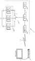
도2는 본 발명의 일 실시예에 따른 통합리모컨의 개략적 외형도이며, 도3은 도2의 통합리모컨의 개략적 블럭도이다. 도4는 통합리모컨의 버튼에 의한 입력신호가 제어부에 인가되는 것을 개략적으로 나타낸 도면이다.FIG. 2 is a schematic external view of an integrated remote control according to an embodiment of the present invention, and FIG. 3 is a schematic block diagram of the integrated remote control of FIG. 4 is a view schematically illustrating that an input signal by a button of the integrated remote controller is applied to the controller.
도2 내지 도4을 참조하면, 본 실시예에 따른 통합리모컨(2)은 입력부(100), 신호송출부(200), 저장부(400), 제어부(300), 스위칭부(500) 및 표시부(520)를 구비한다.2 to 4, the integrated
상기 입력부(100)는 복수의 버튼을 구비한다. 상기 복수의 버튼 중 하나는 통합전원버튼(110)이며, 다른 일부의 버튼은 볼륨변경버튼(120)이며, 또 다른 일부의 버튼 채널변경버튼(130)이다. 상기 볼륨변경버튼(120)은 볼륨을 높이는 볼륨변경버튼(121)과 볼륨을 낮추는 볼륨변경버튼(122)로 이루어져 있으며, 채널변경버튼(130)은 채널번호를 높이는 채널변경버튼(131)과 채널번호를 낮추는 채널변경버 튼(132)로 이루어져 있다.The
입력부(100)의 각 버튼은 서로 구별되는 고유의 입력신호(150)를 발생시킨다. 즉, 통합전원버튼(110)의 입력신호(152), 볼륨변경버튼(120)의 입력신호(154) 및 채널변경버튼(130)의 입력신호(156)는 서로 구별된다.Each button of the
상기 신호송출부(200)는 통합리모컨(2)의 단부에 배치되며, TV(T) 및 셋탑박스(S)를 제어하는 원격제어신호(210)를 송출한다. 신호송출부(200)는 일반적으로 적외선 형태의 원격제어신호(210)를 송출한다.The
상기 저장부(400)는 입력부(100)의 입력신호(150)와 원격제어신호(210)를 서로 대응시켜놓은 매핑테이블(402)을 저장한다. 본 실시예에 있어서, 상기 매핑테이블(402)은 제1 내지 제3매핑테이블(410,420,430)을 포함하여 이루어져 있다.The
상기 제1매핑테이블(410)은 상기 통합전원버튼(110)에 의한 입력신호(152)를 TV 전원을 온 또는 오프시키는 원격제어신호에 대응시킨다. 그리고, 볼륨변경버튼(120)에 의한 입력신호(154)를 TV 볼륨을 변경시키기 위한 원격제어신호(210)에 대응시키며, 채널변경버튼(130)에 의한 입력신호(156)를 TV의 채널을 변경시키기 위한 원격제어신호에 대응시킨다.The first mapping table 410 corresponds to the
이를 정리하면, 아래의 표 1과 같다.In summary, it is shown in Table 1 below.
상기 제2매핑테이블(420)은 상기 통합전원버튼(110)에 의한 입력신호(152)를 셋탑박스의 전원을 온 또는 오프시키는 원격제어신호에 대응시킨다. 그리고, 볼륨변경버튼(120)에 의한 입력신호(154)를 셋탑박스의 볼륨을 변경시키기 위한 원격제어신호에 대응시키며, 채널변경버튼(130)에 의한 입력신호(156)를 셋탑박스의 채널을 변경시키기 위한 원격제어신호에 대응시킨다.The second mapping table 420 corresponds to the
이를 정리하면, 아래의 표 2와 같다.In summary, it is shown in Table 2 below.
상기 제3매핑테이블(430)은 상기 통합전원버튼(110)에 의한 입력신호(152)를 TV 전원과 셋탑박스 전원을 함께 온 또는 오프시키는 원격제어신호에 대응시킨다. TV 전원과 셋탑박스의 전원을 함께 온 또는 오프시키는 원격제어신호는, TV 전원을 온 또는 오프시키는 원격제어신호와 셋탑박스의 전원을 온 또는 오프시키는 원격제어신호를 겹치게 혹은 순차적으로 결합시킴으로써 만들어질 수 있다. 그리고, 볼륨변경버튼(120)에 의한 입력신호(154)를 셋탑박스의 볼륨을 변경시키기 위한 원격제어신호에 대응시키며, 채널변경버튼(130)에 의한 입력신호(156)를 셋탑박스의 채널을 변경시키기 위한 원격제어신호에 대응시킨다.The third mapping table 430 corresponds to an
이를 정리하면, 아래의 표 3와 같다.This is summarized in Table 3 below.
격제어신호The power to turn on and off the TV and the set-top box together.
Control
TV(T) 또는 셋탑박스(S)를 제어하기 위한 원격제어신호(210)는 TV(T) 또는 셋탑박스(S)의 제조사에 따라 차이가 있을 수 있는데, 본 실시예의 통합리모컨(2)은 이를 고려하여 사용자가 제어하고자 하는 기기의 원격제어신호(210)를 미리 매핑테이블(402)에 입력해 두는 방법으로 그 기기를 원격제어할 수 있다. 이러한 방법 외에도, 매핑테이블(402)에 여러 제조사의 기기가 가지는 다양한 원격제어신호를 모두 입력해 둠으로써, 신호송출부(200)가 상기 다양한 원격제어신호를 함께 송출하게 하는 방법으로도 사용자가 제어하고자 하는 기기를 원격제어할 수 있다.
상기 저장부(400)는 통합리모컨(2)의 전원이 없는 경우에도, 매핑테이블(402)이 저장되어 있도록, 비휘발성 메모리로 이루어지는 것이 바람직하다.The
상기 제어부(300)는 버튼의 입력신호(150)를 인가받으며, 저장부(400)에 저장된 매핑테이블(402)을 참조하여, 신호송출부(200)가 입력신호(150)에 대응되는 원격제어신호(210)를 송출하도록 제어한다. 상기 제어부(300)는 저장부(400)에 저장된 매핑테이블(402)에 포함된 제1 내지 제3매핑테이블(410,420,430) 중 하나를 선택적으로 참조한다.The
상기 스위칭부(500)는 제어부(300)가 제1 내지 제3매핑테이블(410,420,430) 중 하나를 선택하여 참조하도록 한다. 즉, 스위칭부(500)는 제어부(300)가 참조하는 제1 내지 제3매핑테이블(410,420,430) 중 하나를 다른 하나로 변경시킨다. 본 실시예에 따른 통합리모컨(2)에 있어서, 스위칭부(500)는 사용자의 의해서 조작되는 스위칭 버튼(510)을 구비하여 이루어진다.The
상기 스위칭 버튼(510)은 사용자가 이를 누를 때마다, 제어부(300)가 참조하는 제1 내지 제3 매핑테이블(410,420,430) 중 하나를 다른 하나로 순차적으로 변경시킨다. 예를 들면, 사용자가 스위칭 버튼(510)을 누를 때마다, 제어부(300)가 참조하는 제1 내지 제3매핑테이블(410,420,430) 중 하나를 제1, 제2 ,제3매핑테이블(41,420,430)의 순서로 순환적으로 변경되도록 할 수 있다.Each time the user presses the
상기 표시부(520)는 제어부(300)가 제1 내지 제3매핑테이블(410,420,430) 중 하나를 참조함에 따라, 그에 대응되게 각기 다른 제1 내지 제3신호를 표시한다. 본 실시예에 있어서, 상기 표시부(520)는 스위칭 버튼(510)의 부근에 배치되며, 제1 내지 제3신호는 표시부(520)에 마련된 제1 내지 제3표시램프(522,524,526)가 각각 점등됨으로 표시된다. 즉, 상기 제1표시램프(522)는 제어부(300)가 제1매핑테이블(410)을 참조할 경우 점등됨으로써 제1신호를 표시하며, 상기 제2표시램프(524)는 제어부(300)가 제2매핑테이블(420)을 참조할 경우 점등됨으로써 제2신호를 표시하며, 상기 제3표시램프(526)는 제어부(300)가 제3매핑테이블(430)을 참조할 경우 점등됨으로써 제3신호를 표시한다. 제1 내지 제3표시램프(522,524,526)는 통합리모컨의 배터리가 빨리 방전되는 것을 막기 위해서, 스위칭 버튼(510)이 눌러질 때만 일시적으로 점등되도록 하는 것이 바람직하다.The
이와 같이, 표시부(520)는 제어부(300)가 제1 내지 제3매핑테이블(410,420,430) 중 어떤 것을 참조하고 있는지를 사용자가 시각적으로 인식할 수 있도록 해주므로, 사용자가 통합리모컨(2)을 통해서 TV(T) 또는 셋탑박스(S) 중 어떤 것을 제어하고 있는지를 알 수 있게 해준다.As such, the
이하, 본 실시예에 따른 통합리모컨(2)의 사용방법에 대해서 설명하도록 한다.Hereinafter, a method of using the integrated
먼저, 본 실시예에 따른 통합리모컨(2)의 제어부(300)가 제3매핑테이블(430)을 참조하는 경우에 대해서 설명한다.First, a case in which the
통합리모컨(2)의 통합전원버튼(110)을 눌러주면, 통합전원버튼(110)에 의한 입력신호(152)가 발생되고, 그 입력신호(152)가 제어부(300)에 인가된다. 제어부(300)는 제3매핑테이블(430)을 참조하여, 신호송출부(200)가 그 입력신호(152)에 대응되는 TV 전원 및 셋탑박스 전원을 함께 온 또는 오프시키는 원격제어신호(210)를 송출하도록, 신호송출부(200)를 제어한다. 따라서, TV 전원 및 셋탑박스 전원은 꺼져 있다가 함께 켜지게 된다.When the integrated
사용자가 셋탑박스(S)로 전송되는 IPTV 방송, 케이블 TV 방송 또는 위성방송 등을 TV로 시청하다가, TV의 볼륨을 변경하고자 하는 경우, 통합리모컨(2)의 볼륨변경버튼(120)를 눌러준다. 그러면, 볼륨변경버튼(120)에 의한 입력신호(154)가 제어부(300)에 인가된다. 제어부(300)는 제3매핑테이블(430)을 참조하여, 신호송출부(200)가 볼륨변경버튼(120)에 의한 입력신호(154)에 대응되는 TV 볼륨을 변경시키는 원격제어신호를 송출하도록 제어한다. TV 볼륨을 변경시키는 원격제어신호가 TV(T)에 도달되면, TV의 볼륨만이 변경되고 셋탑박스의 볼륨은 변경되지 않고 유지된다.When the user watches an IPTV broadcast, cable TV broadcast or satellite broadcast transmitted to the set-top box on a TV, and wants to change the volume of the TV, the user presses the
한편, 셋탑박스의 볼륨은 고정시켜 두는 것이 바람직한데, 이는 셋탑박스의 볼륨이 지나치게 크거나 낮게 설정되어 있는 경우, TV의 볼륨을 키우거나 낮추어도 원하는 정도의 볼륨으로 맞추기가 불편한 경우가 발생하기 때문이다.On the other hand, it is desirable to keep the volume of the set-top box fixed, because if the volume of the set-top box is set too high or too low, it may be inconvenient to adjust the volume of the set-top box to the desired level. to be.
본 실시예에 따른 통합리모컨(2)에 있어서, 제어부(300)가 제3매핑테이블(430)을 참조하고 있는 경우, 일단 셋탑박스의 볼륨을 적절하게 설정해 두면, TV의 볼륨만이 변경되므로, TV의 볼륨이 너무 커지거나 적어지는 것을 방지할 수 있는 장점이 있다.In the integrated
또한, 셋탑박스(S)로 전송되는 IPTV 방송 또는 케이블 방송 등을 TV로 시청하다가, 셋탑박스의 채널을 변경하고자 하는 경우, 통합리모컨(2)의 채널변경버튼(130)를 눌러준다. 그러면, 채널변경버튼(130)에 의한 입력신호(156)가 제어부(300)에 인가된다. 제어부(300)는 제3매핑테이블(430)을 참조하여, 신호송출부(200)가 상기 입력신호(156)에 대응되는 셋탑박스의 채널을 변경시키는 원격제어신호를 송출하도록, 셋탑박스(S)를 제어한다. 셋탑박스의 채널을 변경시키는 원격제어신호가 셋탑박스(S)에 도달되면, TV의 채널은 유지된 채, 셋탑박스의 채널만이 변경된다.In addition, while watching the IPTV broadcast or cable broadcast transmitted to the set-top box (S) on the TV, if you want to change the channel of the set-top box, press the
한편, 셋탑박스(S)를 이용하여 IPTV 방송 또는 케이블 방송 등을 시청하는 경우, TV의 채널을 고정시켜 둔 채, 셋탑박스의 채널만을 변경하는 것이 바람직하다. 이는, 사용자가 다른 방송을 보기 위해서는 TV의 채널이 아닌 셋탑박스의 채널을 바꾸어야 하기 때문이다. 셋탑박스(S)를 이용하여 IPTV 방송 또는 케이블 방송 등을 시청할 경우, TV의 채널은 외부입력 채널에 맞추어져 있기 때문에 TV의 채널을 변경시키는 버튼을 누르더라도 TV의 채널은 변경되지 않는다. 따라서, 사용자가 헛되이 버튼을 누르는 경우가 빈번히 발생한다. 그러나, 본 실시예에 따른 통합리모컨(2)을 사용하면, TV의 채널이 고정된 채 셋탑박스의 채널만이 변경되므로, 사용자가 버튼을 헛되이 누르는 일이 효과적으로 방지될 수 있다.On the other hand, when watching the IPTV broadcast or cable broadcast using the set-top box (S), it is preferable to change only the channel of the set-top box while fixing the channel of the TV. This is because the user must change the channel of the set-top box, not the channel of the TV, to watch another broadcast. When watching an IPTV broadcast or a cable broadcast using the set-top box S, the channel of the TV is not changed even if the button for changing the channel of the TV is pressed because the channel of the TV is tuned to an external input channel. Therefore, a user frequently presses a button in vain. However, using the integrated
사용자가 TV(T) 및 셋탑박스(S)를 별도로 제어할 필요가 있을 경우, 스위칭 버튼(510)을 눌러 제어부(300)가 참조하는 제1 내지 제3매핑테이블(410,420,430) 중 하나를 다른 하나로 변경시킨다. 스위칭 버튼(510)을 누르면 표시부(520)의 제1 내지 제3표시램프(522,524,526) 중 하나가 점등되는데, 사용자가 TV(T)를 별도로 제어하고 싶은 경우에는 제1표시램프(522)가 점등될 때까지 스위칭 버튼을 눌러준다. 마찬가지로 셋탑박스(S)를 별도로 제어하고 싶을 때는 제2표시램프(524)가 점등될 때까지 스위칭 버튼(510)을 눌러준다.When the user needs to control the TV T and the set-top box S separately, one of the first to third mapping tables 410, 420, and 430 referred to by the
이와 같이, 본 실시예에 따른 통합리모컨(2)을 사용할 경우, TV의 전원 및 셋탑박스의 전원을 켜기 위해서, 수차례 버튼을 조작할 필요가 없으므로, 매우 편리하다.As such, when the integrated
또한, 본 실시예의 통합리모컨(2)은 TV의 전원 및 셋탑박스의 전원을 함께 온 또는 오프할 수 있고, TV(T) 및 셋탑박스(S)를 별도로 또는 함께 제어할 수 있으므로 매우 편리하다. 특히, 제어부(300)가 제3매핑테이블(430)을 참조하도록 스위칭부(500)를 설정해 놓은 경우, TV의 채널을 고정시킨 채 셋탑박스의 채널만을 변경하거나, 셋탑박스의 볼륨을 고정시킨 채 TV의 볼륨만을 변경할 수 있으므로 TV(T)와 셋탑박스(S)를 함께 제어하기가 매우 편리하다.In addition, the integrated
한편, 스위칭부(500)는 상기 제어부(300)가 상기 제1 또는 제2매핑테이블(410,420) 중 어느 하나를 참조하다가 상기 제3매핑테이블(430)을 참조하도록 할 때의 조작하는 방법과, 상기 제어부(300)가 제3매핑테이블(430)을 참조하다가 제1 또는 제2매핑테이블(410,420) 중 어느 하나를 참조하도록 할 때의 조작방법이 서로 다르게 마련될 수도 있다. 예를 들면, 스위칭 버튼(510)을 구비한 스위칭부(500)에 있어서, 제어부(300)가 제1 또는 제2매핑테이블(410,420)을 참조하다가 제3매핑테이블(430)을 참조하도록 할 때는 스위칭 버튼(510)을 짧게 눌러도 되도록 하되, 제어부(300)가 제3매핑테이블(430)을 참조하다가 제1 또는 제2매핑테이블(410,420) 중 어느 하나를 참조하도록 할 때는 스위칭 버튼(510)을 길게 눌러야만 되도록 할 수도 있다.On the other hand, the
이와 같이, 제어부(300)가 상기 제1 또는 제2매핑테이블(410,420) 중 어느 하나를 참조하다가 상기 제3매핑테이블(430)을 참조하도록 할 때의 조작 방법과, 상기 제어부(300)가 제3매핑테이블(430)을 참조하다가 제1 또는 제2매핑테이블(410,420) 중 어느 하나를 참조하도록 할 때의 조작 방법을 서로 다르게 해 둠으로써, 사용자는 현재 제어부(300)가 참조하고 있는 것이 제1 또는 제2매핑테이블(410,420)인지 아니면 제3매핑테이블(430)인지를 인식하게 된다.As described above, an operation method when the
특히, 제어부(300)가 제3매핑테이블(430)을 참조하다가 제1 또는 제2매핑테이블(410,420) 중 어느 하나를 참조하도록 할 때는 스위칭 버튼(510)을 길게 눌러야만 되도록 해 둘 경우, 사용자의 부지중에 제어부(300)가 제1 또는 제2매핑테이블(410,420) 중 어느 하나를 참조하도록 설정되는 것이 효과적으로 억제된다. 즉, 제어부(300)가 제3매핑테이블(430)을 참조하도록 하는 것은 용이하게 조작 가능하지만, 제어부(300)가 제3매핑테이블(430)을 참조하다가 제1 또는 제2매핑테이블(410,420) 중 어느 하나를 참조하도록 하는 것은 비교적 용이하지 않게 해둠으로써, 제어부(300)가 제3매핑테이블(430)을 참조하도록 설정되어 있는 것이 유도되는 효과가 있다.Particularly, when the
다음으로, 본 발명의 다른 실시예에 따른 통합리모컨에 대해 도면을 참조하여 설명하도록 한다. 이하, 도2 내지 도4에 도시된 구성과 동일한 도면부호를 가지는 구성은 서로 동일한 구성임을 의미한다.Next, an integrated remote control according to another embodiment of the present invention will be described with reference to the drawings. Hereinafter, the components having the same reference numerals as the components shown in FIGS. 2 to 4 mean the same components.
도5는 본 발명의 다른 실시예에 따른 통합리모컨의 외형을 개략적으로 도시한 도면이다.5 is a view schematically showing the appearance of the integrated remote control according to another embodiment of the present invention.
본 실시예에 따른 통합리모컨(3)은 도2에 도시된 통합리모컨(2)과 스위칭부(500)를 제외하고는 구성이 동일하다.The integrated
본 실시예에 따른 통합리모컨(3)에 있어서, 스위칭부(500)는 딥스위치(550)를 구비하여 이루어져 있다. 상기 딥스위치(550)는 레버(551)를 구비하며, 상기 레버(551)는 제1 내지 제3위치(552,554,556)를 사이를 이동가능하게 배치된다. 딥스위치(550)의 레버(551)가 제1위치(552)에 위치된 경우는 제어부(300)가 제1매핑테이블(410)을 참조하며, 딥스위치(550)의 레버(551)가 제2위치(554)에 위치된 경우는 제어부(300)가 제2매핑테이블(420)을 참조하며, 딥스위치(550)의 레버(551)가 제3위치(556)에 위치된 경우는 제어부(300)가 제3매핑테이블(430)을 참조한다.In the integrated
딥스위치(550)를 사용할 경우, 별도로 표시부를 구비할 필요가 없다.When using the
본 실시예에 따른 통합리모컨(3)도 도2에 도시된 통합리모컨(2)과 효과가 매우 유사하므로 이에 대한 구체적인 설명은 생략하도록 한다.Since the integrated
다음으로, 본 발명의 또 다른 실시예에 따른 통합리모컨에 대해서 설명하도록 한다.Next, an integrated remote control according to another embodiment of the present invention will be described.
도6은 본 발명의 또 다른 실시예에 따른 통합리모컨의 개략적 외형도이다.6 is a schematic external view of an integrated remote control according to another embodiment of the present invention.
본 실시예에 따른 통합리모컨(4)은 통합전원버튼(110)을 구비하고 있어서, TV 및 셋탑박스의 전원을 함께 온 또는 오프할 수 있다.Integrated
도6에 도시된 통합리모컨(4)은 도2에 도시된 통합리모컨(2)에 있어서, 스위칭부(500)가 없는 형태로 구성되어 있다. 본 실시예에 따른 통합리모컨(4)의 저장부(400)에 저장된 매핑테이블(402)은 도2에 도시된 통합리모컨(2)의 제1 내지 제3매핑테이블(410,420,430) 중 제3매핑테이블(430)만을 구비하여 이루어져 있다. 즉, 볼륨변경버튼(120)은 셋탑박스의 볼륨을 고정시킨 채 상기 TV의 볼륨만을 변경하도록, TV의 볼륨을 변경시키는 원격제어신호에 대응되는 입력신호를 상기 제어부(300)에 인가한다. 그리고, 채널변경버튼(130)은 상기 TV의 채널을 고정시킨 채 상기 셋탑박스의 채널만을 조정하도록, 상기 셋탑박스의 채널을 변경시키는 원격제어신호에 대응되는 입력신호를 상기 제어부에 인가한다.The integrated
본 실시예에 따른 통합리모컨(4)의 경우는 TV와 셋탑박스의 전원이 함께 온 또는 오프되므로, 각각의 전원을 별도로 온 또는 오프 해야 하는 불편함이 없으며, 볼륨변경버튼(120)은 TV의 볼륨만을 변경시키고, 채널변경버튼(130)는 셋탑박스의 채널만을 변경하므로 조작이 매우 간단하다. 특히, IPTV 방송 등과 같이 TV와 셋탑박스를 항상 함께 사용하여, TV 또는 셋탑박스를 별도로 제어할 필요가 적은 경우, 버튼의 혼동의 없으므로 더욱 편리하다.In the case of the integrated
다음으로, 본 발명의 또 다른 실시예에 따른 통합리모컨에 대해서 설명하도록 한다.Next, an integrated remote control according to another embodiment of the present invention will be described.
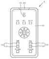
도7은 본 발명의 또 다른 실시예에 따른 통합리모컨의 개략적 외형도이다.7 is a schematic external view of an integrated remote control according to another embodiment of the present invention.
본 실시예에 따른 통합리모컨(5)은 통합전원버튼(110)을 구비하고 있어서, TV 및 셋탑박스의 전원을 함께 온 또는 오프 할 수 있다.Integrated
본 실시예에 따른 통합리모컨(5)의 경우 TV를 제어하기 위한 버튼을 별도로 구비하고 있다. TV를 제어하기 위한 버튼에는 TV 전원버튼(114), TV 볼륨변경버튼(140,142) 및 TV 채널변경버튼(150,152)이 포함되어 있다.In the case of the integrated
또한, 셋탑박스를 제어하기 위한 버튼도 별도로 구비되어 있는데, 이들에는 셋탑박스 전원버튼(112), 셋탑박스 볼륨변경버튼(160,162) 및 셋탑박스 채널변경버튼(170,172)이 포함되어 있다.In addition, a button for controlling the set-top box is also provided separately. These include the set-top
따라서, 본 실시예에 따른 통합리모컨(5)의 경우는, TV(T) 및 셋탑박스(S)를 제어하기 위한 버튼을 별도로 구비하고 있으므로, 도2 및 도5에 도시된 통합리모컨(2,3)과는 달리 스위칭부를 구비할 필요가 없다.Accordingly, in the integrated
본 실시예에 따른 통합리모컨(5)을 사용하면, 상기 실시예들에 따른 통합리모컨(2,3,4)와 마찬가지로, TV 및 셋탑박스의 전원을 함께 온 또는 오프할 수 있어서 편리하다.Using the integrated
한편, 상기 실시예들에서는 통합리모컨을 중심으로 설명하였으나, 본 발명에 따른 통합리모컨은 별도로 제조, 판매 등이 이루어지는 것 외에도, 셋탑박스(S)와 함께 세트로 제조, 판매 등이 이루어질 수도 있다.Meanwhile, in the above embodiments, the integrated remote control has been described. However, the integrated remote control according to the present invention may be manufactured, sold, etc. in addition to the set top box S, in addition to the manufacturing and selling separately.
한편, 도2에 도시된 통합리모컨(2)의 경우, 사용자가 스위칭 버튼(510)을 조작함에 따라서, 통합전원버튼(110)을 이용하여 TV 및 셋탑박스의 전원을 함께 온 또는 오프시킬 수도 있고, 그렇지 않을 수도 있다. 그런데, 이와는 달리, 제1 및 제2매핑테이블(410,420) 모두 통합전원버튼(110)에 의한 입력신호(152)를 TV 및 셋탑박스의 전원을 함께 온 또는 오프 원격제어신호에 대응시킴으로써, 통합전원버튼(110)을 누르면 항상 TV 및 셋탑박스의 전원이 함께 온 또는 오프되도록 할 수도 있다.Meanwhile, in the integrated
또한, 도2에 도시된 통합리모컨(2)의 경우, 제1 내지 제3신호를 표시하기 위해서, 표시부(520)가 제1 내지 제3표시램프(522,524,526)를 구비하는 것으로 설명하였으나, 표시부(520)는 제1 내지 제3신호를 표시하는 액정화면 등으로 구성될 수도 있다.In addition, in the integrated
또한, 도5에 도시된 통합리모컨(3)의 경우, 스위칭부(500)가 딥스위치(550)을 구비하는 것으로 설명하였으나, 딥스위치(550) 대신 로터리 스위치를 구비할 수도 있다.In addition, in the integrated
이상, 본 발명의 일부 실시예에 대해 설명하였으나, 본 발명은 이에 한정되지 않으며, 본 발명의 기술적 사상의 범위 내에서 다양한 형태로 구체화될 수 있다.As mentioned above, although some embodiments of the present invention have been described, the present invention is not limited thereto and may be embodied in various forms within the scope of the technical idea of the present invention.
도1은 종래의 통합리모컨을 개략적으로 도시한 도면이다.1 is a view schematically showing a conventional integrated remote control.
도2는 본 발명의 일 실시예에 따른 통합리모컨의 개략적 외형도이다.2 is a schematic external view of an integrated remote control according to an embodiment of the present invention.
도3은 도2의 통합리모컨의 개략적 블럭도이다.3 is a schematic block diagram of the integrated remote controller of FIG.
도4는 통합리모컨의 버튼에 의한 입력신호가 제어부 인가되는 것을 개략적으로 나타낸 도면이다.4 is a diagram schematically illustrating that an input signal by a button of an integrated remote controller is applied to a controller.
도5은 본 발명의 다른 실시예에 따른 통합리모컨의 외형을 개략적으로 도시한 도면이다.5 is a view schematically showing the appearance of the integrated remote control according to another embodiment of the present invention.
도6은 본 발명의 또 다른 실시예에 따른 통합리모컨의 개략적 외형도이다.6 is a schematic external view of an integrated remote control according to another embodiment of the present invention.
도7은 본 발명의 또 다른 실시예에 따른 통합리모컨의 개략적 외형도이다.7 is a schematic external view of an integrated remote control according to another embodiment of the present invention.
<도면의 주호부호에 대한 설명><Description of Major Symbols in Drawings>
2 ... 통합리모컨 100 ... 입력부2 ... Integrated
110 ... 통합전원버튼120 ... 볼륨변경버튼110 ...
130 ... 채널변경버튼200 ... 신호송출부130 ...
300 ... 제어부400 ... 저장부300 ...
402 ... 매핑테이블410 ... 제1매핑테이블402 ... Mapping Table 410 ... First Mapping Table
420 ... 제2매핑테이블430 ... 제3매핑테이블420 ... second mapping table 430 ... third mapping table
500 ... 스위칭부520 ... 표시부500 ... switching
T ... TVS ... 셋탑박스T ... TV S ... Set Top Box
Claims (8)
Translated fromKoreanPriority Applications (1)
| Application Number | Priority Date | Filing Date | Title |
|---|---|---|---|
| KR1020090117839AKR20110061246A (en) | 2009-12-01 | 2009-12-01 | Integrated remote control and set top box |
Applications Claiming Priority (1)
| Application Number | Priority Date | Filing Date | Title |
|---|---|---|---|
| KR1020090117839AKR20110061246A (en) | 2009-12-01 | 2009-12-01 | Integrated remote control and set top box |
Publications (1)
| Publication Number | Publication Date |
|---|---|
| KR20110061246Atrue KR20110061246A (en) | 2011-06-09 |
Family
ID=44395753
Family Applications (1)
| Application Number | Title | Priority Date | Filing Date |
|---|---|---|---|
| KR1020090117839ACeasedKR20110061246A (en) | 2009-12-01 | 2009-12-01 | Integrated remote control and set top box |
Country Status (1)
| Country | Link |
|---|---|
| KR (1) | KR20110061246A (en) |
Cited By (7)
| Publication number | Priority date | Publication date | Assignee | Title |
|---|---|---|---|---|
| US9024726B2 (en) | 2011-10-11 | 2015-05-05 | Lg Electronics Inc. | Remote controller and control method for a multimedia device |
| KR20170006870A (en)* | 2015-07-10 | 2017-01-18 | 주식회사 엘지유플러스 | Image device, control method tehreof, program, recording medium, remote controller, control method therof |
| KR101881773B1 (en) | 2018-04-26 | 2018-07-25 | 주식회사 오성전자 | Method for power balance used remote controller, and remote controller supporting the same |
| KR20200005218A (en) | 2018-07-06 | 2020-01-15 | 리모트솔루션주식회사 | The power supply synchronization method of TV and set top box |
| KR102211588B1 (en)* | 2019-09-30 | 2021-02-03 | 김경원 | Indoor and outdoor loss prevention system using multi-use terminal and personal smartphone |
| USRE48496E1 (en) | 2012-05-22 | 2021-03-30 | Samsung Electronics Co., Ltd. | Electronic device, system including electronic device and relay apparatus, and control method for the same |
| WO2021117973A1 (en) | 2019-12-09 | 2021-06-17 | 리모트솔루션주식회사 | System for configuring voice recognition rcu by using cloud server, and method therefor |
- 2009
- 2009-12-01KRKR1020090117839Apatent/KR20110061246A/ennot_activeCeased
Cited By (8)
| Publication number | Priority date | Publication date | Assignee | Title |
|---|---|---|---|---|
| US9024726B2 (en) | 2011-10-11 | 2015-05-05 | Lg Electronics Inc. | Remote controller and control method for a multimedia device |
| USRE48496E1 (en) | 2012-05-22 | 2021-03-30 | Samsung Electronics Co., Ltd. | Electronic device, system including electronic device and relay apparatus, and control method for the same |
| KR20170006870A (en)* | 2015-07-10 | 2017-01-18 | 주식회사 엘지유플러스 | Image device, control method tehreof, program, recording medium, remote controller, control method therof |
| KR101881773B1 (en) | 2018-04-26 | 2018-07-25 | 주식회사 오성전자 | Method for power balance used remote controller, and remote controller supporting the same |
| KR20200005218A (en) | 2018-07-06 | 2020-01-15 | 리모트솔루션주식회사 | The power supply synchronization method of TV and set top box |
| KR102211588B1 (en)* | 2019-09-30 | 2021-02-03 | 김경원 | Indoor and outdoor loss prevention system using multi-use terminal and personal smartphone |
| WO2021117973A1 (en) | 2019-12-09 | 2021-06-17 | 리모트솔루션주식회사 | System for configuring voice recognition rcu by using cloud server, and method therefor |
| US12197815B2 (en) | 2019-12-09 | 2025-01-14 | Remote Solution Co., Ltd. | System for setting voice recognition RCU by using cloud server, and method therefor |
Similar Documents
| Publication | Publication Date | Title |
|---|---|---|
| KR20110061246A (en) | Integrated remote control and set top box | |
| US8031056B2 (en) | Remote controller and remote control method | |
| US7224410B1 (en) | Remote control device for a television receiver with user programmable means | |
| EP2164248A2 (en) | Display Apparatus, Remote Controller, Display System and Control Method Thereof | |
| JP2008054085A (en) | Broadcast receiving apparatus and activation method thereof | |
| KR19980086158A (en) | Broadcasting program reservation recording device using remote transceiver | |
| KR20110049006A (en) | Method and apparatus for power control of set top box | |
| KR100748688B1 (en) | Carrier Frequency Setting and Simultaneous Transmission Remote Control System and Method | |
| US20090066854A1 (en) | Universal remote control unit | |
| JP4993145B2 (en) | Remote control device | |
| US20120026410A1 (en) | Information processing apparatus and control method used for the same | |
| KR20070111224A (en) | Integrated remote control and its control method | |
| JP2006343014A (en) | Air conditioning system | |
| JP5908042B2 (en) | Remote control system and remote control device | |
| JP2007295155A (en) | Video display device | |
| JP4660388B2 (en) | Broadcast receiver | |
| KR20060101674A (en) | Control method of DVTV and RCTV TV with a single remote control | |
| KR200311654Y1 (en) | Television remote control device | |
| JP2008167007A (en) | Remote control system | |
| JP2006319838A (en) | Remote controller | |
| KR100915325B1 (en) | A Handy Remote Controller | |
| KR101446410B1 (en) | Smart phone functioning as TV remote controller | |
| KR100606840B1 (en) | Removable Remote Controller | |
| JP2007129309A (en) | Wireless remote control kitchen television receiver | |
| KR20040047518A (en) | device of remote control television |
Legal Events
| Date | Code | Title | Description |
|---|---|---|---|
| A201 | Request for examination | ||
| PA0109 | Patent application | Patent event code:PA01091R01D Comment text:Patent Application Patent event date:20091201 | |
| PA0201 | Request for examination | ||
| E902 | Notification of reason for refusal | ||
| PE0902 | Notice of grounds for rejection | Comment text:Notification of reason for refusal Patent event date:20110322 Patent event code:PE09021S01D | |
| PG1501 | Laying open of application | ||
| E601 | Decision to refuse application | ||
| PE0601 | Decision on rejection of patent | Patent event date:20110726 Comment text:Decision to Refuse Application Patent event code:PE06012S01D Patent event date:20110322 Comment text:Notification of reason for refusal Patent event code:PE06011S01I |