KR20110059520A - Visible light communication system and method - Google Patents
Visible light communication system and methodDownload PDFInfo
- Publication number
- KR20110059520A KR20110059520AKR1020100083528AKR20100083528AKR20110059520AKR 20110059520 AKR20110059520 AKR 20110059520AKR 1020100083528 AKR1020100083528 AKR 1020100083528AKR 20100083528 AKR20100083528 AKR 20100083528AKR 20110059520 AKR20110059520 AKR 20110059520A
- Authority
- KR
- South Korea
- Prior art keywords
- light
- chromaticity
- data
- coordinate
- predetermined
- Prior art date
- Legal status (The legal status is an assumption and is not a legal conclusion. Google has not performed a legal analysis and makes no representation as to the accuracy of the status listed.)
- Ceased
Links
Images


Classifications
- H—ELECTRICITY
- H04—ELECTRIC COMMUNICATION TECHNIQUE
- H04B—TRANSMISSION
- H04B1/00—Details of transmission systems, not covered by a single one of groups H04B3/00 - H04B13/00; Details of transmission systems not characterised by the medium used for transmission
- H04B1/62—Details of transmission systems, not covered by a single one of groups H04B3/00 - H04B13/00; Details of transmission systems not characterised by the medium used for transmission for providing a predistortion of the signal in the transmitter and corresponding correction in the receiver, e.g. for improving the signal/noise ratio
- H—ELECTRICITY
- H04—ELECTRIC COMMUNICATION TECHNIQUE
- H04B—TRANSMISSION
- H04B10/00—Transmission systems employing electromagnetic waves other than radio-waves, e.g. infrared, visible or ultraviolet light, or employing corpuscular radiation, e.g. quantum communication
- H04B10/11—Arrangements specific to free-space transmission, i.e. transmission through air or vacuum
- H04B10/114—Indoor or close-range type systems
- H04B10/1141—One-way transmission
- H—ELECTRICITY
- H04—ELECTRIC COMMUNICATION TECHNIQUE
- H04B—TRANSMISSION
- H04B10/00—Transmission systems employing electromagnetic waves other than radio-waves, e.g. infrared, visible or ultraviolet light, or employing corpuscular radiation, e.g. quantum communication
- H04B10/11—Arrangements specific to free-space transmission, i.e. transmission through air or vacuum
- H04B10/114—Indoor or close-range type systems
- H04B10/116—Visible light communication
- H—ELECTRICITY
- H04—ELECTRIC COMMUNICATION TECHNIQUE
- H04B—TRANSMISSION
- H04B10/00—Transmission systems employing electromagnetic waves other than radio-waves, e.g. infrared, visible or ultraviolet light, or employing corpuscular radiation, e.g. quantum communication
- H04B10/50—Transmitters
Landscapes
- Engineering & Computer Science (AREA)
- Computer Networks & Wireless Communication (AREA)
- Signal Processing (AREA)
- Physics & Mathematics (AREA)
- Electromagnetism (AREA)
- Optical Communication System (AREA)
Abstract
Description
Translated fromKorean본 발명은 통신 시스템 및 방법에 관한 것으로써, 특히 가시광을 이용하여 통신하는 가시광 통신 시스템 및 방법에 관한 것이다.TECHNICAL FIELD The present invention relates to communication systems and methods, and more particularly to visible light communication systems and methods for communicating using visible light.
최근, 가시광 영역의 빛을 이용한 광 통신 기술이 주목되고 있다. 특히, 발광 다이오드(LED; Light Emitting Diode) 등의 발광 소자를 이용한 조명 장치의 보급이 급속히 진행되고 있는 상황을 배경으로 하고, 옥내외에 설치된 조명 장치를 활용하고, 편리성이 뛰어난 데이터 통신 환경(가시광 통신 시스템)을 실현시키기 위한 연구 개발이 진행되고 있다. 광 통신에 이용되는 발광 소자로서는, 인체나 의료 기기 등에 대한 영향을 고려하면 LED가 가장 유력한 후보가 된다. 그러나, 광 통신에 의한 데이터 전송 속도는, 발광 소자나 구동 회로의 응답 속도에 의존한다. 그 때문에, 고속의 데이터 전송 속도를 필요로 하는 용도로, LED보다도 응답 속도가 높은 LD(Laser Diode)나 SLD(Super Luminescent Diode)가 유력한 후보가 된다.Recently, optical communication technology using light in the visible light region has been attracting attention. In particular, in the background of the rapidly spreading of lighting devices using light emitting elements such as light emitting diodes (LEDs), utilizing lighting devices installed indoors and outdoors, and having excellent convenience in data communication environment (visible light) Research and development for realizing communication system). As a light emitting element used for optical communication, LED is the most likely candidate in consideration of the influence on a human body, a medical device, or the like. However, the data transfer rate by optical communication depends on the response speed of the light emitting element and the driving circuit. Therefore, LD (Laser Diode) or SLD (Super Luminescent Diode), which has a higher response speed than LED, is a promising candidate for applications requiring a high data transfer rate.
또한, 적색, 녹색, 청색의 LED를 이용하고, LED가 발하는 1시그널 간에 많은 데이터를 안정되게 전송하기 위한 방법도 모색되고 있다. 이러한 방법으로서는, 예를 들면, 색도 다중 전송 방식이 있다. 적색, 녹색, 청색의 LED를 이용할 경우, 각LED의 발광 강도를 적절히 제어함으로써, 수신측에서 관측되는 빛의 색도를 제어할 수 있다. 상기 색도 다중 전송 방식은, 임의의 표색계의 색도 좌표 상에 복수의 심볼점을 설정해 두고, 이들의 심볼점에 복수 비트의 데이터를 매핑하여 전송하는 방식이다. 임의의 심볼점에 데이터가 매핑 되면, 그 심볼점에 대응하는 색도의 빛이 수신측에서 수신되는 바와 같이 각 LED의 발광 강도가 제어된다.In addition, a method of using a red, green, and blue LED and stably transmitting a large amount of data between one signal emitted by the LED is also being sought. As such a method, for example, there is a chromaticity multiplex transmission method. When red, green, and blue LEDs are used, the chromaticity of the light observed from the receiving side can be controlled by appropriately controlling the light emission intensity of each LED. In the chromaticity multiplex transmission method, a plurality of symbol points are set on chromaticity coordinates of an arbitrary color system, and a plurality of bits of data are mapped to these symbol points and transmitted. When data is mapped to any symbol point, the light emission intensity of each LED is controlled as light of the chromaticity corresponding to the symbol point is received at the receiving side.
각 LED의 발광 강도에 대한 제어는, 각LED에 인가되는 전류 펄스의 크기를 제어함으로써 실현된다. 여기에서 문제가 되는 것이 LED의 발광 특성에 나타나는 비선형성이다. 대부분의 경우, 전류 펄스의 증가에 따라 LED의 발광 강도는 비선형으로 증가한다(도 4를 참조). 이러한 LED의 비선형 특성을 무시하여 발광 제어하면, 수신측에서 관측되는 빛의 색도가 색도 좌표 상의 심볼점으로부터 어긋나 버린다. 이러한 심볼점으로부터의 어긋남을 방지하기 위해서는, 예를 들면, LED의 비선형 특성을 고려한 복잡한 전류를 제어하든가, 심볼점으로부터의 어긋남을 예측하여 어긋남을 보상할 필요가 있다.Control of the light emission intensity of each LED is realized by controlling the magnitude of the current pulse applied to each LED. The problem here is the nonlinearity exhibited in the light emission characteristics of the LED. In most cases, the luminous intensity of the LED increases nonlinearly with the increase of the current pulse (see FIG. 4). When the light emission control is ignored while ignoring the nonlinear characteristics of the LED, the chromaticity of the light observed on the receiving side is shifted from the symbol point on the chromaticity coordinate. In order to prevent such a deviation from the symbol point, for example, it is necessary to control a complicated current in consideration of the nonlinear characteristics of the LED or to predict the deviation from the symbol point to compensate for the deviation.
가시광 통신 시스템에 관해서, 상기와 같은 색도의 어긋남을 보상하는 방법에 대해서는 전혀 알려져 있지 않다. 그러나, 무선 통신 시스템의 송신 회로가 가지는 비선형 특성에 기인하는 비선형 왜곡 보상 방법에 대해서는, 예를 들면, 일본 특허공개 제2001-203609호 및 일본 특허공개 제2006-295766호에 기재된 방법이 알려져 있다. 일본 특허공개 제2001-203609호에는, 비선형 회로에 선형 변조 신호를 통하게 할 경우에 발생하는 진폭 왜곡을 수신측에서 추정하고, 그 추정 결과를 바탕으로 수신 신호의 진폭 왜곡을 보상하는 무선 통신 시스템의 구성이 개시되어 있다. 또한, 일본 특허공개 제2006-295766호에는, 트레이닝(training) 동작에 의해 초기 비선형 왜곡 보상 계수(심볼점으로부터의 편차량)를 산출하고, 그 초기 비선형 왜곡 보상 계수를 이용하여 수신 신호에 생기는 비선형 왜곡을 보상하는 구성이 개시되어 있다.As for the visible light communication system, there is no known method for compensating for the chromaticity deviation as described above. However, as for the nonlinear distortion compensation method due to the nonlinear characteristics of the transmission circuit of the wireless communication system, for example, the methods described in Japanese Patent Laid-Open Nos. 2001-203609 and 2006-295766 are known. Japanese Patent Laid-Open No. 2001-203609 discloses a wireless communication system for estimating amplitude distortion that occurs when a nonlinear circuit is passed through a linear modulated signal, and compensating amplitude distortion of a received signal based on the estimation result. The configuration is disclosed. In addition, Japanese Patent Laid-Open No. 2006-295766 calculates an initial nonlinear distortion compensation coefficient (deviation amount from a symbol point) by a training operation, and uses the initial nonlinear distortion compensation coefficient to generate a nonlinearity in a received signal. A configuration for compensating for distortion is disclosed.
그러나, 전술한 종래기술에 기재된 방법은 모두 수신 신호에 생기는 비선형 왜곡을 보상하기 위해서 성상도(Constellation) 상에 설정된 심볼점으로부터의 편차량을 추정하는 처리가 포함되어 있다. 이러한 추정 처리를 실현하기 위해서는, 어느 정도 복잡한 회로 구성을 필요로 한다. 한편, 가시광 통신 시스템의 경우, 무선 통신 시스템에 비하여, 거리가 짧고, 전망이 좋은 전송로를 통하여 직진성(rectilinearity)이 좋은 빛에 의해 통신이 이루어진다. 그 때문에, 무선 통신 시스템과 같이 전송로의 상태가 복잡하게 변화되는 것은 드물다.However, the above-described methods described in the related art all include processing for estimating the amount of deviation from the symbol point set on the constellation in order to compensate for the nonlinear distortion occurring in the received signal. In order to realize such estimation processing, a somewhat complicated circuit configuration is required. On the other hand, in the visible light communication system, communication is performed by light having a shorter distance and good rectilinearity than a wireless communication system through a transmission path having a good view. Therefore, the state of the transmission path is rarely changed like a wireless communication system.
또한, 비선형 왜곡의 원인이 되는 주된 구성 요소는 발광 소자나 수광 소자에 한정된다. 그 때문에, 발광 소자나 수광 소자의 고정적인 비선형 특성을 고려해 두면, 상기 무선 통신 시스템의 왜곡 보상 방법과 같은 복잡한 처리는 불필요하다.In addition, the main component which causes a nonlinear distortion is limited to a light emitting element or a light receiving element. Therefore, considering the fixed nonlinear characteristics of the light emitting element and the light receiving element, complicated processing such as the distortion compensation method of the wireless communication system is unnecessary.
본 발명은 전술한 점을 고려하여 안출된 것으로써, 단순한 구성에서, 광원이나 수광 소자의 비선형 특성에 기인하여 생기는 비선형 왜곡을 효과적으로 보상할 수 있는 신규 또한 개량된 가시광 통신 시스템 및 가시광 통신 방법을 제공하는데 그 목적이 있다.SUMMARY OF THE INVENTION The present invention has been made in view of the foregoing, and provides, in a simple configuration, a novel and improved visible light communication system and a visible light communication method which can effectively compensate for nonlinear distortion caused by nonlinear characteristics of a light source or a light receiving element. Its purpose is to.
상기 과제를 해결하기 위해서, 본 발명의 일 측면에 따른 송신장치는, 서로 다른 색의 빛을 발광하는 복수의 광원과, 데이터를 소정의 색도 좌표값으로 변환하는 데이터 변환부와, 상기 각 광원의 발광 강도를 제어하여, 상기 데이터 변환부에 의한 변환에서 얻어진 색도 좌표값에 대응하는 색도의 빛을 발광시키는 데이터 송신부와, 상기 데이터 송신부에 의한 발광 제어 전에 상기 각 광원의 발광 강도를 제어하여, 모든 상기 소정의 색도 좌표값에 대응하는 색도의 빛을 발광시키는 사전 발광부를 포함한다.MEANS TO SOLVE THE PROBLEM In order to solve the said subject, the transmission apparatus which concerns on one aspect of this invention consists of the several light source which emits the light of a different color, the data conversion part which converts data into predetermined chromaticity coordinate value, and A data transmission unit for controlling the light emission intensity to emit light of chromaticity corresponding to the chromaticity coordinate value obtained by the conversion by the data conversion unit, and controlling the light emission intensity of each light source before light emission control by the data transmission unit, And a pre-light emitting unit which emits light of chromaticity corresponding to the predetermined chromaticity coordinate value.
본 발명의 다른 측면에 따른 수신장치는, 송신장치에 구비된 복수의 광원으로부터 방출된 빛을 수광하는 수광 소자와, 상기 수광한 빛의 색도에 의거하여 상기 소정의 색도 좌표값을 나타내는 좌표 정보를 설정하는 좌표 설정부와, 상기 좌표 설정부에 의해 설정된 좌표 정보를 이용하여, 수광한 빛의 색도를 상기 데이터로 변환하는 데이터 역변환부를 포함한다.According to another aspect of the present invention, a receiving apparatus includes: a light receiving element for receiving light emitted from a plurality of light sources included in a transmitting device; and coordinate information indicating the predetermined chromaticity coordinate value based on the chromaticity of the received light. And a data inverse transform unit for converting the chromaticity of the received light into the data using the coordinate setting unit to be set and the coordinate information set by the coordinate setting unit.
이와 같이, 상기 가시광 통신 시스템은, 데이터를 색도 좌표값에 변조 매핑 하여 송신하는 송신장치와, 수광 소자에 의해 수광한 빛의 색도로부터 원래의 데이터를 복조하는 수신장치를 포함한다. 대부분의 경우, 광원이나 수광 소자의 특성, 전송로의 특성 등 (이하, 전송계의 특성 특히 비선형 왜곡)에 기인하여, 송신측에서 매핑한 색도 좌표값과, 수신측에서 관측되는 빛의 색도가 나타내는 색도 좌표값은 어긋나 버린다. 이와 같이, 복조에 이용하는 색도 좌표값에 어긋남이 생기면, 복조 정밀도가 저하되고, 에러율이 증가하게 된다. 하지만, 상기한 바와 같이, 변조 매핑에 사용하는 모든 소정의 색도 좌표값에 대응하는 색도의 빛을 수신측을 향하여 미리 발광하고, 수신측에서는 수광한 빛의 색도에 의거하여 복조에 이용하는 소정의 색도 좌표값을 설정해 둠으로써, 전송계의 특성을 고려한 복조 처리가 가능해지고, 복조 정밀도가 향상되어 에러율을 감소시킬 수 있게 된다.As described above, the visible light communication system includes a transmitting device for modulating and transmitting data to chromaticity coordinate values, and a receiving device for demodulating original data from the chromaticity of light received by the light receiving element. In most cases, the chromaticity coordinate values mapped at the transmitting side and the chromaticity of light observed at the receiving side due to the characteristics of the light source or the light receiving element, the characteristics of the transmission path (hereinafter, the characteristics of the transmission system, in particular nonlinear distortion). The chromaticity coordinate values shown are shifted. In this way, if a deviation occurs in the chromaticity coordinate value used for demodulation, the demodulation accuracy is lowered and the error rate is increased. However, as described above, light of chromaticity corresponding to all predetermined chromaticity coordinate values used for modulation mapping is emitted in advance toward the receiving side, and the predetermined chromaticity coordinates used for demodulation based on the chromaticity of the received light on the receiving side. By setting the value, demodulation processing in consideration of the characteristics of the transmission system can be performed, and the demodulation accuracy can be improved and the error rate can be reduced.
또한, 상기 송신장치의 사전 발광부는, 상기 데이터 송신부에 의한 발광 제어 전에, 상기 복수의 광원에 대하여, 상기 모든 소정의 색도 좌표값에 대응하는 색도의 빛을 반복하여 발광시키도록 구성될 수 있다. 이 경우, 상기 수신장치의 좌표 설정부는, 상기 수광 소자에 의해 반복하여 수광한 빛의 색도에 의거하여 상기 좌표 정보를 설정한다. 이와 같이, 소정의 색도 좌표값에 대응하는 색도의 빛을 반복하여 송신하고, 각 색도 좌표값에 관하여 복수의 관측값으로부터 좌표 정보를 설정함으로써, 평균적인 전송계의 특성을 고려한 좌표 정보의 설정이 가능해진다. 예를 들면, 어떤 색도 좌표값을 설정할 시에, 그 색도 좌표값에 대해서 관측된 복수의 색도의 평균을 내고, 그 평균값을 복조에 이용하도록 구성하면 된다.The pre-light emitting unit of the transmitting device may be configured to repeatedly emit light of chromaticity corresponding to all the predetermined chromaticity coordinate values with respect to the plurality of light sources before the light emission control by the data transmitting unit. In this case, the coordinate setting unit of the receiver sets the coordinate information based on the chromaticity of light repeatedly received by the light receiving element. In this way, by repeatedly transmitting light of a chromaticity corresponding to a predetermined chromaticity coordinate value, and setting coordinate information from a plurality of observation values with respect to each chromaticity coordinate value, setting of coordinate information in consideration of the characteristics of an average transmission system is achieved. It becomes possible. For example, when setting a chromaticity coordinate value, what is necessary is just to comprise the average of the some chromaticity observed with respect to the chromaticity coordinate value, and to use the average value for demodulation.
나아가, 상기 수신장치의 좌표 설정부는, 상기 수광 소자에 의해 상기 소정의 순서로 수광한 빛의 색도를 그대로 소정의 색도 좌표값에 할당함으로써 상기 좌표 정보를 설정한다. 상기한 바와 같이, 수신측에서 수광한 빛의 색도는, 전송계의 특성에 의해 왜곡을 포함하고 있다. 고주파 대역의 전파를 이용하는 무선 통신의 분야에서는, 전송계의 특성을 추정하고, 그 전송계에서 발생하는 왜곡을 추정하고, 추정한 왜곡량을 보상하기 위한 파라미터를 산출하며, 산출한 파라미터를 이용하여 수신 신호의 왜곡을 보상하는 방법이 이용된다. 한편, 상기 가시광 통신 시스템에서는, 수신장치에서 조금도 추정 처리 등을 수행하지 않고, 단순하게 수광한 빛의 색도를 소정의 색도 좌표값으로 설정하여 이용한다. 그 때문에, 불필요한 연산 부하가 걸리지 않고, 회로 구성이 단순하여 회로 설계나 전력 절약화가 용이해진다.Further, the coordinate setting unit of the receiving apparatus sets the coordinate information by allocating the chromaticity of the light received by the light receiving element in the predetermined order as it is to a predetermined chromaticity coordinate value. As described above, the chromaticity of the light received at the receiving side includes distortion due to the characteristics of the transmission system. In the field of wireless communication using radio waves in a high frequency band, the characteristics of a transmission system are estimated, the distortion occurring in the transmission system is estimated, a parameter for compensating the estimated distortion amount is calculated, and the calculated parameter is used. A method of compensating for distortion of the received signal is used. On the other hand, in the visible light communication system, the chromaticity of light received simply is set to a predetermined chromaticity coordinate value without performing any estimation process or the like in the reception apparatus. Therefore, unnecessary computational load is not applied, and the circuit configuration is simple, which facilitates circuit design and power saving.
또한, 상기 과제를 해결하기 위해서, 본 발명의 다른 측면에 따른 송신장치는, 서로 다른 색의 빛을 발광하는 복수의 광원과, 데이터를 소정의 색도 좌표값으로 변환하는 데이터 변환부와, 상기 각 광원의 발광 강도를 제어하여, 상기 데이터 변환부에 의한 변환에서 얻어진 색도 좌표값에 대응하는 색도의 빛을 발광시키는 데이터 송신부와, 상기 데이터 송신부에 의한 발광 제어 전에, 상기 각 광원의 발광 강도를 제어하여, 상기 소정의 색도 좌표값의 일부에 대응하는 색도의 빛을 발광시키는 사전 발광부를 가지는 송신장치를 구비한다.Moreover, in order to solve the said subject, the transmission apparatus which concerns on the other aspect of this invention is a light source which emits the light of a different color, the data conversion part which converts data into predetermined chromaticity coordinate value, and each said, The light emission intensity of the light source is controlled to control the light emission intensity of the light source, and the light emission intensity of each light source is controlled before the light emission control by the data transmission unit. And a transmitting device having a pre-light emitting part for emitting light of chromaticity corresponding to a part of the predetermined chromaticity coordinate value.
또한, 본 발명의 다른 측면에 따른 수신장치는, 상기 송신장치에 구비된 광원으로부터 방출된 빛을 수광하는 수광 소자와, 상기 수광한 빛의 색도를 상기 소정의 색도 좌표값의 일부를 나타내는 제 1 좌표 정보에 설정하는 제 1 좌표 설정부와, 상기 제 1 좌표 설정부에 의해 설정된 제 1 좌표 정보를 이용하여, 상기 소정의 색도 좌표값의 일부를 제외하는 나머지의 상기 소정의 색도 좌표값을 산출하고, 산출 결과를 상기 나머지의 소정의 색도 좌표값을 나타내는 제 2 좌표 정보에 설정하는 제 2 좌표 설정부와, 상기 제 1또는 제 2 좌표 설치부에 의해 설정된 제 1 또는 제 2 좌표 정보를 이용하여, 수광한 빛의 색도를 상기 데이터로 변환하는 데이터 역변환부를 구비한다.In addition, the receiving apparatus according to another aspect of the present invention, the first receiving unit for receiving the light emitted from the light source provided in the transmitting device, and the chromaticity of the received light indicating a part of the predetermined chromaticity coordinate value The remaining predetermined chromaticity coordinate values excluding a part of the predetermined chromaticity coordinate values are calculated using the first coordinate setting unit set in the coordinate information and the first coordinate information set by the first coordinate setting unit. And using a second coordinate setting unit that sets the calculation result to second coordinate information indicating the remaining predetermined chromaticity coordinate value, and first or second coordinate information set by the first or second coordinate mounting unit. And a data inverse converter for converting the chromaticity of the received light into the data.
상기한 바와 같이, 변조 매핑에 사용하는 모든 소정의 색도 좌표값에 대응하는 색도의 빛을 수신장치를 향해서 미리 발광하고, 수신장치에서는, 수광한 빛의 색도에 의거하여 복조에 이용하는 소정의 색도 좌표값을 설정해 둠으로써 전송계의 특성을 고려한 복조 처리가 가능해지고, 복조 정밀도가 향상되며, 에러율를 감소시킬 수 있게 된다. 또한, 소정의 색도 좌표값의 일부 만을 송신 하도록 구성함으로써, 색도 좌표값의 송신에 필요한 통신량을 감소시킬 수 있다.As described above, light of chromaticity corresponding to all predetermined chromaticity coordinate values used for modulation mapping is previously emitted to the receiving apparatus, and the receiving apparatus uses predetermined chromaticity coordinates for demodulation based on the chromaticity of the received light. By setting the value, demodulation processing in consideration of characteristics of the transmission system can be performed, demodulation accuracy can be improved, and error rate can be reduced. In addition, by configuring only a portion of the predetermined chromaticity coordinate values, it is possible to reduce the amount of communication required for transmission of the chromaticity coordinate values.
또한, 상기 과제를 해결하기 위해서, 본 발명의 또 다른 측면에 따른 데이터 송신 방법은, 서로 다른 색의 빛을 발광하는 복수의 광원에 대하여, 상기 각 광원의 발광 강도를 제어하여, 모든 상기 소정의 색도 좌표값에 대응하는 색도의 빛을 발광시키는 단계와, 데이터를 소정의 색도 좌표값으로 변환하는 단계와, 송신측에서, 상기 각 광원의 발광 강도를 제어하여, 상기 변환에 의해 얻어진 색도 좌표값에 대응하는 색도의 빛을 발광시키는 데이터 송신 단계를 포함한다.Moreover, in order to solve the said subject, the data transmission method which concerns on another aspect of this invention controls the light emission intensity of each said light source with respect to the some light source which emits light of a different color, and all the said predetermined | prescribed Emitting light having a chromaticity corresponding to the chromaticity coordinate value, converting the data into a predetermined chromaticity coordinate value, and controlling the emission intensity of each light source on the transmitting side, thereby obtaining the chromaticity coordinate value obtained by the conversion. And a data transmission step of emitting light of chromaticity corresponding to the.
또한, 본 발명의 또 다른 측면에 따른 데이터 수신 방법은 송신장치로부터 방출된 빛을 수광하는 수광 소자에 의해 방출된 빛을 수광하고, 수광한 빛의 색도에 의거하여 상기 소정의 색도 좌표값을 나타내는 좌표 정보를 설정하는 단계와, 상기 방출된 빛을 상기 수광 소자에 의해 수광하고, 상기 설정된 좌표 정보를 이용하여, 수광한 빛의 색도를 상기 데이터로 변환하는 단계 포함하는 가시광 통신 방법이 제공된다.In addition, the data receiving method according to another aspect of the present invention receives the light emitted by the light receiving element for receiving the light emitted from the transmission device, and displays the predetermined chromaticity coordinate value based on the chromaticity of the received light And setting coordinate information, and receiving the emitted light by the light receiving element, and converting the chromaticity of the received light into the data using the set coordinate information.
상기한 바와 같이, 변조 매핑에 사용하는 모든 소정의 색도 좌표값에 대응하는 색도의 빛을 수신장치를 향해서 미리 발광하고, 수신장치에서는 수광한 빛의 색도에 의거하여 복조에 이용하는 소정의 색도 좌표값을 설정해 둠으로써 전송계의 특성을 고려한 복조 처리가 가능해지고, 복조 정밀도가 향상되며, 에러율를 감소시킬 수 있게 된다.As described above, light of chromaticity corresponding to all predetermined chromaticity coordinate values used for modulation mapping is previously emitted to the receiving apparatus, and the receiving apparatus uses predetermined chromaticity coordinate values for demodulation based on the chromaticity of the received light. By setting this value, demodulation processing in consideration of the characteristics of the transmission system can be performed, demodulation accuracy can be improved, and error rate can be reduced.
또한, 상기 과제를 해결하기 위해서, 본 발명의 또 다른 측면에 따른 데이터 송신 방법은, 서로 다른 색의 빛을 발광하는 복수의 광원에 대하여 상기 각 광원의 발광 강도를 제어하여, 모든 상기 소정의 색도 좌표값의 일부에 대응하는 색도의 빛을 발광시키는 단계와, 데이터를 소정의 색도 좌표값으로 변환하는 단계와, 송신측에서 상기 각 광원의 발광 강도를 제어하여, 상기 변환에 의해 얻어진 색도 좌표값에 대응하는 색도의 빛을 발광시키는 데이터를 송신하는 단계를 포함한다.Moreover, in order to solve the said subject, the data transmission method which concerns on another aspect of this invention controls the light emission intensity of each said light source with respect to the some light source which emits light of a different color, and all said predetermined chromaticities Emitting light of a chromaticity corresponding to a part of the coordinate value, converting data into a predetermined chromaticity coordinate value, and controlling the emission intensity of each light source on the transmitting side, thereby obtaining the chromaticity coordinate value obtained by the conversion. Transmitting data that emits light of chromaticity corresponding to.
또한, 본 발명의 또 다른 측면에 따른 데이터 수신 방법은 송신장치에 구비된 광원으로부터 방출된 빛을 수광하는 수광 소자에 의하여 상기 사전 발광 단계에서 방출된 빛을 수광하고, 수광한 빛의 색도에 의거하여 상기 소정의 색도 좌표값의 일부를 나타내는 제 1 좌표 정보를 설정하는 제 1 좌표 설정 단계와, 상기 제 1 좌표 설정 단계에서 설정된 제 1 좌표 정보를 이용하여 상기 소정의 색도 좌표값의 일부를 제외하는 나머지의 상기 소정의 색도 좌표값을 산출하고, 산출 결과를 상기 나머지의 소정의 색도 좌표값을 나타내는 제 2 좌표 정보에 설정하는 제 2 좌표 설정 단계와, 상기 송신장치로부터 방출된 빛을 상기 수광 소자에 의해 수광하고, 상기 제 1 또는 제 2 좌표 설정 단계에서 설정된 제 1 또는 제2 좌표 정보를 이용하여 수광한 빛의 색도를 상기 데이터로 변환하는 데이터 역변환 스텝을 포함한다.In addition, the data receiving method according to another aspect of the present invention receives the light emitted in the pre-emission step by a light receiving element for receiving the light emitted from the light source provided in the transmitter, and based on the chromaticity of the received light A first coordinate setting step of setting first coordinate information indicating a part of the predetermined chromaticity coordinate value and a part of the predetermined chromaticity coordinate value using the first coordinate information set in the first coordinate setting step A second coordinate setting step of calculating the remaining predetermined chromaticity coordinate values, and setting the calculation result to second coordinate information representing the remaining predetermined chromaticity coordinate values; and receiving the light emitted from the transmitting device. The chromaticity of the light received by the device and received by using the first or second coordinate information set in the first or second coordinate setting step is obtained. And a data inverse transformation step of converting the data into existing data.
상기한 바와 같이, 변조 매핑에 사용하는 모든 소정의 색도 좌표값에 대응하는 색도의 빛을 수신측을 향해서 미리 발광하고, 수신측에서는 수광한 빛의 색도에 의거하여 복조에 이용하는 소정의 색도 좌표값을 설정해 둠으로써 전송계의 특성을 고려한 복조 처리가 가능해지고, 복조 정밀도가 향상되며, 에러율를 감소시킬 수 있게 된다. 또한, 소정의 색도 좌표값의 일부 만을 송신 하도록 구성함으로써, 색도 좌표값의 송신에 필요한 통신량을 감소시킬 수 있다.As described above, light of chromaticity corresponding to all predetermined chromaticity coordinate values used for modulation mapping is previously emitted toward the receiving side, and the receiving side uses the predetermined chromaticity coordinate value used for demodulation based on the chromaticity of the received light. By setting, the demodulation process in consideration of the characteristics of the transmission system can be performed, the demodulation accuracy can be improved, and the error rate can be reduced. In addition, by configuring only a portion of the predetermined chromaticity coordinate values, it is possible to reduce the amount of communication required for transmission of the chromaticity coordinate values.
이상에서 설명한 바와 같이, 본 발명에 따르면, 단순한 구성으로 광원이나 수광 소자의 비선형 특성에 기인하여 발생하는 수신 심볼점의 왜곡을 효과적으로 보상할 수 있게 된다.As described above, according to the present invention, it is possible to effectively compensate for the distortion of the received symbol point caused by the nonlinear characteristics of the light source or the light receiving element with a simple configuration.
도 1은 색도 좌표 다중 방식에 관한 가시광 통신 시스템의 구성예를 나타내는 설명도,
도 2는 색도 좌표계로의 변조 매핑 방법의 일 예를 나타내는 설명도,
도 3은 색도 좌표계로의 변조 매핑 방법의 일 예를 나타내는 설명도,
도 4는 전송계의 비선형 특성을 설명하기 위한 설명도,
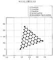
도 5는 전송계의 비선형 특성에 기인해서 생기는 송수신 심볼점의 어긋남을 나타내는 설명도,
도 6은 본 발명의 일 실시예에 관한 가시광 통신 시스템의 구성예를 나타내는 설명도,
도 7은 본 발명의 일 실시예에 관한 트레이닝 신호 및 데이터 신호의 프레임 구성예를 나타내는 설명도,
도 8은 본 발명의 일 실시예에 관한 왜곡 보상 방법 및 상기 왜곡 보상 방법을 적용했을 경우에 얻어진 BER의 개선 효과를 나타내는 설명도,
도 9는 본 발명의 일 실시예에 관한 왜곡 보상 방법을 적용했을 경우에 얻어진 BER의 개선 효과를 나타내는 설명도.1 is an explanatory diagram showing a configuration example of a visible light communication system according to a chromaticity coordinate multiplexing method;
2 is an explanatory diagram showing an example of a modulation mapping method in a chromaticity coordinate system;
3 is an explanatory diagram showing an example of a modulation mapping method in a chromaticity coordinate system;
4 is an explanatory diagram for explaining a nonlinear characteristic of a transmission system;
5 is an explanatory diagram showing deviation of transmission / reception symbol points caused by nonlinear characteristics of a transmission system;
6 is an explanatory diagram showing a configuration example of a visible light communication system according to an embodiment of the present invention;
7 is an explanatory diagram showing a frame configuration example of a training signal and a data signal according to an embodiment of the present invention;
8 is an explanatory diagram showing an improvement effect of BER obtained when the distortion compensation method and the distortion compensation method according to an embodiment of the present invention are applied;
9 is an explanatory diagram showing an improvement effect of BER obtained when the distortion compensation method according to an embodiment of the present invention is applied.
이하 본 발명에 따른 바람직한 실시예를 첨부한 도면을 참조하여 상세히 설명한다. 하기 설명에서는 구체적인 구성 소자 등과 같은 특정 사항들이 나타나고 있는데 이는 본 발명의 보다 전반적인 이해를 돕기 위해서 제공된 것일 뿐 이러한 특정 사항들이 본 발명의 범위 내에서 소정의 변형이나 혹은 변경이 이루어질 수 있음은 이 기술분야에서 통상의 지식을 가진 자에게는 자명하다 할 것이다.Hereinafter, exemplary embodiments of the present invention will be described in detail with reference to the accompanying drawings. In the following description, specific matters such as specific elements are shown, which are provided to help a more general understanding of the present invention. It is self-evident to those of ordinary knowledge in Esau.
이하에 기재하는 본 발명의 실시예에 관한 설명의 흐름에 대해서 간단하게 설명한다. 우선, 도 1을 참조하면서, 색도 다중 전송 방식에 관한 가시광 통신 시스템(10)의 시스템 구성에 관하여 설명한다. 이 중에서, 도 2, 도 3을 참조하면서 색도 다중 전송 방식에 관한 색도 좌표계로의 변조 매핑 방법에 관하여 설명한다. 다음으로, 도 4, 도 5를 참조하면서 가시광 통신 시스템(10)에서의 전송계의 비선형 특성에 관하여 설명한다.The flow of description concerning the Example of this invention described below is briefly demonstrated. First, with reference to FIG. 1, the system structure of the visible
다음으로, 도 6을 참조하여 본 발명의 일 실시예에 관한 가시광 통신 시스템 (20)의 구성에 관하여 설명한다. 그 다음에, 도 7을 참조하여, 가시광 통신 시스템 20에서 이용되는 트레이닝(training) 신호 및 데이터 신호의 프레임 구성에 관하여 설명한다. 이어서, 도 8, 도 9를 참조하여, 상기 실시예에 관한 왜곡 보상 방법 및 상기 왜곡 보상 방법을 적용하였을 경우에 얻어지는 BER(Bit Error Rate)의 개선 효과에 관하여 설명한다.Next, with reference to FIG. 6, the structure of the visible
본 발명의 실시예에 관한 기술에 관하여 설명하기에 앞서서, 당해 기술에 관련되는 색도 다중 전송 방식에 근거하는 데이터 전송 방법(예를 들면, 일본 특허공제2007-8091744호 참조)에 대해서 간단하게 설명한다. 여기에서 말하는 색도 다중 전송 방식이란, 어떤 표색계의 색도 좌표 상에 복수의 심볼점을 설정해 두고, 데이터를 심볼점에 매핑하며, 그 심볼점에 대응하는 색도의 빛을 이용하여 데이터를 전송하는 방식을 의미한다. 심볼점에 대응하는 색도의 빛은, 예를 들면, 적색, 녹색, 청색의 LED의 발광 강도를 적절하게 제어하고, 각 LED로부터 방출된 빛을 공간적으로 다중화시킴으로써 얻어진다.Prior to describing the technology relating to the embodiment of the present invention, a data transmission method (for example, see Japanese Patent No. 2007-8091744) based on the chromaticity multiple transmission method related to the technology will be described briefly. . The chromaticity multiple transmission method described herein refers to a method of setting a plurality of symbol points on chromaticity coordinates of a color system, mapping data to symbol points, and transmitting data using chromatic light corresponding to the symbol points. it means. Light of chromaticity corresponding to a symbol point is obtained by appropriately controlling the light emission intensity of red, green, and blue LEDs, for example, and spatially multiplexing the light emitted from each LED.
색도 다중 전송 방식의 경우, 색도 좌표 상에 다수의 심볼점을 배치할 수 있기 때문에, 1심볼점 당 할당 가능한 비트수(다중도)를 크게 함으로써, LED의 응답 속도를 고속화하지 않고 데이터 전송 속도를 향상시킬 수 있다. 상기한 바와 같이, 색도 다중 전송 방식의 경우, 데이터를 적색광, 녹색광, 청색광의 발광 강도비와 전체 발광 강도와의 조합으로 변조하고 있다. 그 때문에, 전송로에서 전체 발광 강도가 감쇠된다 하더라도, 발광 강도비에는 영향을 끼치지 않는다. 결과적으로, 발광 강도비의 정보에 의거하여 비교적 높은 정밀도로 원래의 데이터를 복조할 수 있게 되어 고속이면서 안정된 데이터 전송이 실현된다.In the case of the chromaticity multiple transmission method, since a large number of symbol points can be arranged on chromaticity coordinates, by increasing the number of bits (multiplicity) that can be allocated per symbol point, the data transmission rate can be increased without increasing the response speed of the LED. Can be improved. As described above, in the chromaticity multiplex transmission system, data is modulated by a combination of the light emission intensity ratios of the red light, the green light, and the blue light and the total light emission intensity. Therefore, even if the total light emission intensity is attenuated in the transmission path, it does not affect the light emission intensity ratio. As a result, the original data can be demodulated with a relatively high accuracy based on the information of the light emission intensity ratio, thereby achieving high speed and stable data transmission.
[1-1 : 가시광 통신 시스템(10)의 구성][1-1: Configuration of Visible Light Communication System 10]
이하, 도 1을 참조하여, 색도 다중 전송 방식에 관한 가시광 통신 시스템(10)의 구성에 관하여 설명한다. 도 1을 참조하여, 색도 다중 전송 방식에 관한 가시광 통신 시스템(10)의 구성예를 나타내는 설명도이다. 가시광 통신 시스템(10)은, 데이터를 표색계(color system)의 색도 좌표(chromaticity coordinates) 상에 설정된 소정의 심볼점(예를 들면, 도 2를 참조)에 매핑하고, 상기 심볼점에 대응하는 색도의 빛을 이용하여 데이터를 전송한다.Hereinafter, with reference to FIG. 1, the structure of the visible
도 1에 도시하는 바와 같이, 가시광 통신 시스템(10)은, 송신장치(100)와, 수신장치(200)로 구성된다. 송신장치(100)는, 데이터를 소정의 심볼점에 매핑 하고, 그 심볼점에 대응하는 색도의 빛으로 수신장치(200)에 데이터를 송신한다. 이 때, 송신장치(100)는, 적색, 녹색, 청색의 발광 소자에 각각 적절한 전류량의 전류 펄스를 인가하고, 각 발광 소자로부터 방출된 빛의 공간 다중광이 상기 색도를 가지도록 제어한다. 수신장치(200)는, 송신장치(100)로부터 수광한 빛의 색도와 색도 좌표 상에 설정된 소정의 심볼점을 비교하여 원래의 데이터를 복조한다. 이하, 송신장치(100) 및 수신장치(200)의 구성에 관하여 보다 상세하게 설명한다.As shown in FIG. 1, the visible
(송신장치(100)의 구성)(Configuration of the transmitter 100)
우선, 송신장치(100)의 구성에 관하여 설명한다.First, the structure of the
도 1에 도시하는 바와 같이, 송신장치(100)는, 색 좌표 변조부(102)와, 좌표계 변환부(104)와, D/A변환부(106)와, 광원(108)으로 구성된다. 다만, 광원 (108)은, 복수의 발광 소자를 포함한다. 예를 들면, 광원(108)은, 적색, 녹색, 청색의 LED를 포함한다. 다만, 광원(108)은, LED를 대신하여, LD나 SLD등의 반도체 발광 소자, 형광등, 브라운관(CRT) 디스플레이, 플라즈마 디스플레이(PDP), 유기 전계 발광(EL) 디스플레이, 액정 디스플레이(LCD) 등을 포함하여도 된다. 또한, 광원(108)은, 각 발광 소자를 구동하기 위한 구동 회로를 포함한다.As shown in FIG. 1, the
우선, 송신장치(100)로부터 수신장치(200)로 송신되는 데이터는, 색 좌표 변조부(102)에 입력된다. 데이터가 입력되면, 색 좌표 변조부(102)는, 입력 데이터(디지털 값)를 소정의 표색계의 색도 좌표 상에 배치된 소정의 심볼점(예를 들면, 도 2를 참조)에 매핑한다. 소정의 표색계로서, 예를 들면, 국제 조명 위원회(CIE ; Commission Internationale de l'Eclairage)에 의해 규정된 CIE 표색계(RGB, XYZ(Yxy), L"-u"-v"-, L"-a"-b"- 등), 먼셀(Munsell) 표색계, 오스트발트(Ostwald) 표색계 등이 이용된다.First, data transmitted from the
여기에서, 데이터를 색도 좌표 상의 심볼점에 매핑하는 변조 처리에 대해서, 도 2을 참조하여 더 구체적으로 설명한다. 다만, 도 2는, Yxy 표색계이다. 도 2의 예에서는, 2비트의 데이터(00, 01, 10, 11)에 각각 대응하는 4개의 심볼점이 설정되어 있다. 이들의 심볼점 배치에 근거하여, 예를 들면, 데이터(10)는, x≒0.23, y≒0.14에 위치하는 심볼점에 매핑된다. 도 2의 예에서는, 심볼점의 수가 22=4이지만, 도 3(64심볼점의 예)에 도시하는 바와 같이, 보다 많은 심볼점을 설정하여 전송 속도를 임의로 증가시키는 것도 가능하다. 물론, 데이터를 심볼점에 매핑하는 조작은, 심볼점의 수가 증가하더라도 동일하게 이루어진다.Here, modulation processing for mapping data to symbol points on chromaticity coordinates will be described in more detail with reference to FIG. 2. 2 is a Yxy color system. In the example of FIG. 2, four symbol points corresponding to two bits of data (00, 01, 10, 11) are set. Based on these symbol point arrangements, for example, the
이제, 다시 도 1을 참조하여 설명한다. 상기한 바와 같이 데이터가 심볼점에 매핑되면, 그 심볼점의 색도 좌표값(x, y)은, 좌표계 변환부 104로 입력된다. 색도 좌표값(x, y)이 입력되면, 좌표계 변환부(104)는, 입력된 색도 좌표값(x, y)에 대응하는 색도를 재현하기 위한 적색, 녹색, 청색의 휘도를 산출한다. 적색광의 휘도를 R, 녹색광의 휘도를 G, 청색광의 휘도를 B로 표기하면, 색도 좌표값(x, y)은, 휘도(R, G, B)를 이용하여 하기의 수학식 1 및 2와 같이 표현된다. 그 때문에, 하기의 수학식 1 및 2를 반대로 풀어서 색도 좌표값(x, y)으로부터 휘도(R, G, B)를 얻을 수 있다.Now, description will be made with reference to FIG. 1 again. When data is mapped to a symbol point as described above, the chromaticity coordinate values (x, y) of the symbol point are input to the coordinate


따라서, 좌표계 변환부(104)는, 상기 수학식 1 및 2에 근거하여, 색도 좌표값(x, y)을 휘도(R, G, B)로 변환한다. 좌표계 변환부(104)에 의한 변환 처리에 의해 얻어진 휘도(R, G, B)는, D/A변환부(106)로 입력된다. 휘도(R, G, B)가 입력되면, D/A변환부(106)는, 적색광의 휘도R, 녹색광의 휘도G, 청색광의 휘도B에 따른 강도의 구동 전압을 발생시키고, 각 색의 빛을 발광하는 발광 소자(광원(108))에 인가한다. 구동 전압이 인가되면, 광원(108)에 포함되는 각 색의 발광 소자로부터 휘도(R, G, B)에 따른 빛이 방출된다. 이와 같이 하여, 광원(108)으로부터 방출된 빛은, 공간적으로 다중화하여 수신장치(200)에 도달한다.Therefore, the coordinate
게다가, 광원(108)에 PWM(Pulse Width Modulation) 제어에 대응한 조명 기기를 이용할 경우, 1펄스의 빛으로 휘도(R, G, B)를 재현하는 것은 어렵다. 따라서, 소정 시간 내에 광원(108)으로부터 방출된 빛의 적산 광량으로부터 휘도(R, G, B)를 재현하는 구성으로 해도 된다. 이 경우, 광원(108)으로부터 방출된 빛을 색마다 소정 시간 축적함으로써, 그 적산 광량으로부터 휘도(R, G, B)를 얻을 수 있다. 예를 들면, PWM 주기에 맞추어서 적산 광량과 색도 좌표값(x, y)을 대응 지음으로써, PWM 제어에 의한 영향을 제거하는 것이 가능해진다.In addition, in the case of using a lighting device corresponding to PWM (Pulse Width Modulation) control for the
이상, 송신장치(100)의 구성에 관하여 설명하였다.In the above, the structure of the
(수신장치(200)의 구성)(Configuration of Receiver 200)
다음으로, 수신장치(200)의 구성에 관하여 설명한다.Next, the configuration of the
도 1에 도시하는 바와 같이, 수신장치(200)는, 수광 소자(202)와, A/D변환부(204)와, 좌표계 변환부(206)와, 색 좌표 복조부(208)로 구성된다. 또한, 수광 소자(202)는, 각 색에 대응하는 컬러 필터 및 광전 변환 소자로 구성된다. 광전 변환 소자로서는, 예를 들면, PD(Photo Diode ; pn형 PD, pin형 PD, Avalanche PD 등)가 이용된다.As shown in FIG. 1, the
우선, 송신장치(100)에 의해 발광된 빛은, 수광 소자(202)에 의해 수광된다. 수광 소자(202)는, 컬러 필터에 의해 각 색의 빛을 분리하고, 색 마다 구비된 광전 변환 소자에 의해 수광량에 따른 전류를 발생시킨다. 수광 소자(202)에서 발생한 전류는, A/D변환부(204)에 입력되고, 전류량에 따른 디지털 신호(R, G, B)로 변환된다. 상기 디지털 신호(R, G, B)는, 휘도(R, G, B)에 대응한다. 또한, 상기 디지털 신호(R, G, B)는, 좌표계 변환부(206)에 입력된다.First, the light emitted by the transmitting
디지털 신호(R, G, B)가 입력되면, 좌표계 변환부(206)는, 상기 수학식 1 및 식 2에 근거하여, 디지털 신호(R, G, B)를 색도 좌표값(x, y)으로 변환한다. 좌표계 변환부(206)에 의한 변환 처리에서 얻어진 색도 좌표값(x, y)은, 색 좌표 복조부(208)에 입력된다. 색도 좌표값(x, y)이 입력되면, 색 좌표 복조부(208)는, 입력된 색도 좌표값(x, y)과 색도 좌표 상에 설정된 심볼점의 위치를 비교하고, 색도 좌표값(x, y)에 가장 가까운 심볼점을 선택한다. 그리고, 색 좌표 복조부(208)는, 선택한 심볼점에 대응하는 데이터를 출력한다.When the digital signals R, G, and B are input, the coordinate
이상, 수신장치(200)의 구성에 관하여 설명하였다.The configuration of the
이상에서 설명한 바와 같이, 가시광 통신 시스템(10)은, 데이터를 색도 좌표 상의 심볼점에 매핑하여 전송하기 때문에, 광원(108)에 포함되는 발광 소자의 수를 넘는 다치수(multi-value number)의 데이터를 전송하는 것이 가능해진다. 그 결과, 1 펄스로 송신 가능한 데이터량이 증대되고, 보다 고속의 데이터 전송이 실현된다. 또한, 색광의 휘도비에 데이터를 싣고 있기 때문에, 전송로에서의 광량 감쇠의 영향이 줄어들게 된다. 결과적으로, 전송 에러율을 감소시킬 수 있다. 게다가, 색도 좌표 상의 자유로운 위치에 심볼점을 설정할 수 있기 때문에, 발광색이나 전송 속도의 설계 자유도가 높다. 그리고, 다른 색 다중 방식에 비하여 전송로에서의 빛의 감쇠나 외란(disturbance)의 영향에 강하다고 하는 이점이 있다.As described above, since the visible
[1-2 : 비선형 왜곡에 대해서][1-2: Nonlinear Distortion]
이와 같이, 색도 다중 전송 방식을 적용하면 뛰어난 전송 특성을 얻을 수 있다. 그러나, 색도 다중 전송 방식의 전송 신호는 다치 변조(multi-level modulation) 신호이기 때문에, 뛰어난 전송 특성을 유지하기 위해서는, RGB의 각각에 대해서 전송로의 선형성을 필요로 한다. 만약, 광원(108)의 발광 소자, 구동 회로, 광 전송로, 수광 소자(202)의 광전 변환 소자 등 (이하, 전송계)에 비선형 특성이 존재하면, 전송 특성이 저하하게 된다. 예를 들면, 도 4에 도시하는 바와 같은 비선형 특성을 가지는 전송계를 통해서, 도 3에 도시하는 송신 심볼점(십자점)을 송신하면, 도 5에 도시하는 검고 둥근 모양과 같이 송신 심볼점으로부터의 어긋남이 생기게 된다. 이와 같은 송신 심볼점으로부터의 어긋남이 생기면, 데이터를 복조할 시에 에러가 발생하여, 전송 품질이 저하하게 된다.As such, when chromaticity multiple transmission is applied, excellent transmission characteristics can be obtained. However, since the transmission signal of the chromaticity multiple transmission method is a multi-level modulation signal, the linearity of the transmission path is required for each of RGB in order to maintain excellent transmission characteristics. If non-linear characteristics exist in the light emitting element of the
일반적으로 이용되고 있는 LED의 경우, 가시광 통신을 목적으로서 설계되어 있지 않아, 충분한 선형 특성을 기대할 수는 없다. 특히, 조명용 LED의 구동 회로는, 대전류에 의한 제어가 전제로 되어 있고, 선형 특성을 고려하여 설계되는 일은 없다. 따라서, 일반적인 조명 기기 등을 이용하여 가시광 통신을 수행하는 시스템에 색도 다중 전송 방식을 적용하고자 하면, 전송계의 비선형 특성에 기인해서 전송 품질이 저하되는 문제점이 있다. 그러나, 무선 통신 시스템에서 이용되고 있는 비선형 왜곡의 보상 방법을 적용하는 것은 과잉이며, 회로 규모나 소비 전력의 증대를 초래하게 된다. 따라서, 본건 발명자는, 가시광 통신 시스템에 적합한 단순한 구성으로, 전송계의 비선형 특성에 기인해서 생기는 전송 품질의 저하를 보상하는 방법을 고안하였다. 이하에서는, 이러한 방법에 관하여 상세하게 설명한다.In the case of LEDs which are generally used, they are not designed for visible light communication, and therefore, sufficient linear characteristics cannot be expected. In particular, the driving circuit of the LED for illumination is based on the premise of control by a large current, and is not designed in consideration of a linear characteristic. Accordingly, when the chromaticity multiple transmission scheme is applied to a system for performing visible light communication using a general lighting device, transmission quality is deteriorated due to the nonlinear characteristics of the transmission system. However, the application of the nonlinear distortion compensation method used in the wireless communication system is excessive, resulting in an increase in circuit size and power consumption. Therefore, the present inventor has devised a method of compensating for the degradation of transmission quality caused by the nonlinear characteristics of the transmission system with a simple configuration suitable for a visible light communication system. This method will be described in detail below.
<2 : 실시예><2: Example>
본 발명의 일 실시예에 관하여 설명한다. 본 실시예는, 색도 다중 전송 방식에 관한 가시광 통신에 있어서, 전송계의 비선형 특성에 기인하는 전송 품질의 저하를 보상하는 방법에 관한 것이다.An embodiment of the present invention will be described. The present embodiment relates to a method of compensating for a decrease in transmission quality due to nonlinear characteristics of a transmission system in visible light communication relating to chromaticity multiplex transmission.
[2-1 : 가시광 통신 시스템(20)의 구성][2-1: Configuration of Visible Light Communication System 20]
우선, 도 6을 참조하여, 본 실시예에 관한 가시광 통신 시스템(20)의 시스템 구성에 관하여 설명한다. 도6은, 본 실시예에 관한 가시광 통신 시스템(20)의 시스템 구성예를 나타내는 설명도이다. 도 6의 예는, 도 1에 도시한 가시광 통신 시스템(10)에 본 실시예의 기술을 적용한 것이다. 그 때문에, 가시광 통신 시스템(10)의 구성 요소와 실질적으로 동일한 기능을 가지는 구성 요소 또는 관련성 있는 구성 요소에 관해서는 동일한 부호를 붙였다.First, with reference to FIG. 6, the system structure of the visible
도 6에 도시하는 바와 같이, 가시광 통신 시스템(20)은, 송신장치(100)와 수신장치(200)로 구성된다. 송신장치(100)는, 데이터를 소정의 심볼점에 매핑 하고, 그 심볼점에 대응하는 색도의 빛으로 수신장치(200)에 데이터를 송신한다. 이 때, 송신장치(100)는, 적색, 녹색, 청색의 발광 소자에 각각 적절한 전류량의 전류 펄스를 인가하고, 각 발광 소자로부터 방출된 빛의 공간 다중광이 상기 색도를 가지도록 제어한다.As shown in FIG. 6, the visible
수신장치(200)는, 송신장치(100)로부터 수광한 빛의 색도와 색도 좌표 상에 설정된 소정의 심볼점을 비교하여 원래의 데이터를 복조한다. 이때, 전송계에 비선형 특성이 존재하면, 소정의 심볼점으로부터의 어긋남이 커지고, 이에 의하여 복조 에러가 발생하게 된다. 따라서, 가시광 통신 시스템(20)은, 수신장치(200)가 유지하는 소정의 심볼점에 관한 정보(이하, 좌표 정보)를 적절하게 갱신하고, 전송계의 비선형 특성을 고려한 좌표 정보로 대체한다. 이하, 송신장치(100) 및 수신장치(200)의 구성에 관하여 보다 상세하게 설명한다.The
(송신장치(100)의 구성)(Configuration of the transmitter 100)
우선, 송신장치(100)의 구성에 관하여 설명한다.First, the structure of the
도 6에 도시하는 바와 같이, 송신장치(100)는, 색 좌표 변조부(102)와, 좌표계 변환부(104)와, D/A변환부(106)와, 광원(108)과, 조정 심볼 송신부(110)로 구성된다. 다만, 광원(108)은, 복수의 발광 소자를 포함한다. 예를 들면, 광원(108)은, 적색, 녹색, 청색의 LED를 포함한다. 다만, 광원(108)은, LED대신에, LD나 SLD등의 반도체 발광 소자, 형광등, 브라운관(CRT) 디스플레이, 플라즈마 디스플레이(PDP), 유기 전계 발광(EL) 디스플레이, 액정 디스플레이(LCD) 등을 포함하여도 된다. 또한, 광원(108)은, 각 발광 소자를 구동하기 위한 구동 회로를 포함한다.As shown in FIG. 6, the
우선, 송신장치(100)로부터 수신장치(200)로 송신되는 데이터는, 색 좌표 변조부(102)에 입력된다. 데이터가 입력되면, 색 좌표 변조부(102)는, 입력 데이터(디지털 값)를 소정의 표색계의 색도 좌표 상에 배치된 소정의 심볼점에 매핑한다. 소정의 표색계로서, 예를 들면, 국제 조명 위원회(CIE ; Commission Internationale de l'Eclairage)에 의해 규정된 CIE 표색계(RGB, XYZ(Yxy), L"-u"-v"-, L"-a"-b"- 등), 먼셀(Munsell) 표색계, 오스트발트(Ostwald) 표색계 등이 이용된다.First, data transmitted from the
데이터가 심볼점에 매핑되면, 그 심볼점의 색도 좌표값(x, y)은, 좌표계 변환부(104)에 입력된다. 색도 좌표값(x, y)이 입력되면, 좌표계 변환부(104)는, 상기 수학식 1 및 2에 근거하여, 색도 좌표값(x, y)을 휘도(R, G, B)로 변환한다. 좌표계 변환부(104)에 의한 변환 처리에 의해 얻어진 휘도(R, G, B)는, D/A변환부(106)에 입력된다. 휘도(R, G, B)가 입력되면, D/A변환부(106)는, 적색광의 휘도R, 녹색광의 휘도G, 청색광의 휘도B에 따른 세기의 구동 전압을 발생시키고, 각 색의 빛을 발광하는 발광 소자(광원(108))에 인가한다. 구동 전압이 인가되면, 광원(108)에 포함되는 각 색의 발광 소자로부터 휘도(R, G, B)에 따른 빛이 방출된다. 이와 같이 하여, 광원(108)으로부터 방출된 빛은, 공간적으로 다중화하여 수신장치(200)에 도달한다.When data is mapped to a symbol point, the chromaticity coordinate values (x, y) of the symbol point are input to the coordinate
이와 같이, 데이터를 송신하는 방법은, 가시광 통신 시스템(10)과 실질적으로 동일하다. 그러나, 본 실시예에 관한 송신장치(100)는, 조정 심볼 송신부(110)를 더 구비하고 있다. 조정 심볼 송신부(110)는, 수신장치(200)가 유지하는 좌표 정보를 갱신하기 위한 트레이닝 신호를 송신하는 수단이다. 또한, 트레이닝 신호와 구별하기 위해서, 이하의 설명에서는, 데이터를 변조하여 얻어진 송신 신호를 데이터 신호라 칭한다. 우선, 조정 심볼 송신부(110)는, 트레이닝 신호로서, 색도 좌표 상에 설정된 모든 심볼점의 색도 좌표값(x, y)을 순차적으로 좌표계 변환부(104)에 입력한다. 다만, 트레이닝 신호로서 송신되는 심볼점의 송신 순서는 미리 설정되어 있는 것으로 한다.In this manner, the method of transmitting data is substantially the same as that of the visible
색도 좌표값(x, y)이 입력되면, 좌표계 변환부(104)는, 전술한 상기 수학식 1 및 2에 근거하여, 색도 좌표값(x, y)을 휘도(R, G, B)로 변환한다. 좌표계 변환부(104)에 의한 변환 처리에 의해 얻어진 휘도(R, G, B)는, D/A변환부(106)에 입력된다. 휘도(R, G, B)가 입력되면, D/A변환부(106)는, 적색광의 휘도R, 녹색광의 휘도G, 청색광의 휘도B에 따른 세기의 구동 전압을 발생시키고, 각 색의 빛을 발광하는 발광 소자(광원(108))에 인가한다. 구동 전압이 인가되면, 광원(108)에 포함되는 각 색의 발광 소자로부터 휘도(R, G, B)에 따른 빛이 방출된다. 즉, 모든 심볼점에 대응하는 색도의 빛이 수신장치(200)를 향해서 순차적으로 송신된다.When the chromaticity coordinate values (x, y) are input, the coordinate
이상, 송신장치(100)의 구성에 관하여 설명하였다.In the above, the structure of the
(프레임 구성)(Frame composition)
이하, 도 7을 참조하여, 트레이닝 신호(A) 및 데이터 신호(B)의 프레임 구성에 관하여 설명한다. 트레이닝 신호(A), 데이터 신호(B)는, 예를 들면, 도 7에 도시하는 프레임 구성을 가진다. 도 7에 도시하는 바와 같이, 트레이닝 신호(A) 및 데이터 신호(B)는, 선두 부분에 프리앰블 신호를 가진다. 상기 프리앰블 신호는, 신호 검출 및 타이밍 동기에 사용하는 동기 신호(Sync.)와, RGB 캘리브레이션(calibration)에 사용하는 캘리브레이션 신호(RGB cal.)로 구성된다. RGB 캘리브레이션이란, 전송계에서 발생하는 RGB간의 강도 밸런스를 보정하거나, RGB간의 간섭을 제거하는 처리를 말한다.Hereinafter, the frame structure of the training signal A and the data signal B will be described with reference to FIG. 7. The training signal A and the data signal B have the frame structure shown in FIG. 7, for example. As shown in FIG. 7, the training signal A and the data signal B have a preamble signal at the head part. The preamble signal is composed of a synchronization signal (Sync.) Used for signal detection and timing synchronization, and a calibration signal (RGB cal.) Used for RGB calibration. RGB calibration refers to a process of correcting intensity balance between RGB generated in a transmission system or removing interference between RGB.
전송계의 비선형 특성을 보상할 경우, 데이터 신호(B)의 송신 프레임(이하, 데이터 프레임)을 송신하기에 앞서, 트레이닝 신호(A)의 송신 프레임(이하, 트레이닝 프레임)이 송신된다. 다만, 가시광 통신 시스템(20)은, 데이터 프레임을 송신할 때마다 매회 트레이닝 프레임을 송신하는 것이 아니고, 정기적으로 또는 소정의 타이밍으로 트레이닝 프레임을 송신하도록 구성되어도 된다. 도 7에 도시하는 바와 같이, 트레이닝 프레임은, 프리앰블 신호가 배치되는 선두 부분과, 프리앰블 신호가 배치되는 후단 부분으로 구성된다. 후단 부분에는, 모든 심볼점에 대응하는 색도 좌표값 Ci=(xi, yi)이 포함된다.When compensating for the nonlinear characteristic of the transmission system, before transmitting the transmission frame (hereinafter, referred to as a data frame) of the data signal B, a transmission frame (hereinafter, referred to as a training frame) of the training signal A is transmitted. However, the visible
예를 들면, 도 3에 도시하는 심볼점 배치의 경우, 64개의 심볼점에 대응하는 색도 좌표값C1, C2, …, C64가 후단 부분에 포함된다. 또한, 트레이닝 프레임의 프레임 길이가 충분히 길 경우에, 후단 부분은, 색도 좌표점 C1, C2, …, C64의 반복으로 구성된다. 상기 트레이닝 프레임은, 전송계를 통하여 수신장치(200)에 송신된다. 그 때문에, 수신장치(200)에서 수신한 트레이닝 프레임의 후단 부분은, 전송계의 비선형 특성에 의한 영향을 받아서, 색도 좌표값 C1, C2, …, C64와는 다른 색도 좌표값 C1', C2', …, C64'가 된다. 후술하는 바와 같이, 본 실시예에 관한 수신장치(200)는, 상기 색도 좌표값 C1', C2', …, C64'를 새로운 좌표 정보로 설정하고, 새로운 좌표 정보를 기준으로 해서 데이터 프레임에서 송신된 데이터를 복조한다.For example, in the case of the symbol point arrangement shown in Fig. 3, the chromaticity coordinate values C1 , C2 ,..., Corresponding to 64 symbol points. , C64 is included in the latter part. Further, when the frame length of the training frame is sufficiently long, the rear end portions are provided with chromaticity coordinate points C1 , C2 ,. , It consists of repetition of C64 . The training frame is transmitted to the receiving
이상, 프레임 구성에 관하여 설명하였다.The frame configuration has been described above.
(수신장치(200)의 구성)(Configuration of Receiver 200)
다음으로, 수신장치(200)의 구성에 관하여 설명한다.Next, the configuration of the
도 6에 도시하는 바와 같이, 수신장치(200)는, 수광 소자(202)와, A/D변환부(204)와, 좌표계 변환부(206)와, 색 좌표 복조부(208)와, 동기 검지부(210)와, 평균화부(212)와, 기억부(214)로 구성된다. 또한, 수광 소자(202)는, 각 색에 대응하는 컬러 필터 및 광전 변환 소자로 구성된다. 게다가, 광전 변환 소자로서는, 예를 들면, PD(Photo Diode ; pn형 PD, pin형 PD, Avalanche PD 등)가 이용된다.As shown in FIG. 6, the
우선, 송신장치(100)에 의해 발광된 빛은, 수광 소자(202)에 의해 수광된다. 수광 소자(202)는, 컬러 필터에 의해 각 색의 빛을 분리하고, 색 마다 구비된 광전 변환 소자에 의해 수광량에 따른 전류를 발생시킨다. 수광 소자(202)에서 발생한 전류는, A/D변환부(204)에 입력되고, 전류량에 따른 디지털 신호(R, G, B)로 변환된다. 상기 디지털 신호(R, G, B)는, 휘도(R, G, B)에 대응한다. 또한, 상기 디지털 신호(R, G, B)는, 좌표계 변환부(206)에 입력된다.First, the light emitted by the transmitting
디지털 신호(R, G, B)가 입력되면, 좌표계 변환부(206)는, 상기 수학식 1 및 식 2에 근거하여, 디지털 신호(R, G, B)를 색도 좌표값(x, y)으로 변환한다. 좌표계 변환부(206)에 의한 변환 처리에서 얻어진 색도 좌표값(x, y)은, 색 좌표 복조부 (208)에 입력된다. 색도 좌표값(x, y)이 입력되면, 색 좌표 복조부(208)는, 입력된 색도 좌표값(x, y)과 색도 좌표 상에 설정된 심볼점의 위치를 비교하여, 색도 좌표값(x, y)에 가장 가까운 심볼점을 선택한다. 그리고, 색 좌표 복조부(208)는, 선택한 심볼점에 대응하는 데이터를 출력한다.When the digital signals R, G, and B are input, the coordinate
이와 같이, 데이터를 수신하는 방법은, 가시광 통신 시스템(10)과 실질적으로 동일하다. 그러나, 본 실시예에 관한 수신장치(200)는, 동기 검지부(210), 평균화부(212), 기억부(214)를 더 구비하고 있다. 이들의 구성 요소는, 송신장치(100)로부터 송신된 트레이닝 프레임에 의거하여 좌표 정보를 갱신하는 수단이다.As such, the method of receiving data is substantially the same as that of the visible
트레이닝 프레임에 대해서, 송신장치(100)에 의해 발광된 빛은, 수광 소자 (202)에 의해 수광된다. 수광 소자(202)는, 컬러 필터에 의해 각 색의 빛을 분리하고, 색 마다 구비된 광전 변환 소자에 의해 수광량에 따른 전류를 발생시킨다. 수광 소자(202)에서 발생한 전류는, A/D변환부(204)에 입력되고, 전류량에 따른 디지털 신호로 변환된다. 상기 디지털 신호는, 동기 검지부(210)에 입력된다. 동기 검지부(210)는, 입력된 트레이닝 프레임의 디지털 신호로부터 동기 신호를 검출하고, 그 검출 결과로부터 트레이닝 프레임의 도착 및 선두 위치를 검지한다.The light emitted by the transmitting
또한, 동기 검지부(210)는, 동기 신호의 종류에 근거하여, 입력된 디지털 신호가 트레이닝 프레임의 것인지, 데이터 프레임의 것인지를 식별한다. 동기 신호에는, 예를 들면, PN(Pseudorandom Noise) 부호가 이용된다. 특히, 자기 상관 특성에 뛰어나고, 타이밍 검출에 적합한 M계열이 자주 이용된다. 예를 들면, 트레이닝 프레임과 데이터 프레임에서 다른 M계열이 동기 신호에 할당되어 있다면, 동기 검지부(210)는, M계열의 차이로부터 트레이닝 프레임과 데이터 프레임을 식별할 수 있다. 입력된 디지털 신호가 트레이닝 프레임의 것이었을 경우, 동기 검지부(210)는, 수신장치(200)를 구성하는 다른 구성 요소에 대하여 좌표 정보의 갱신 처리를 개시시키도록 트레이닝 프레임의 도착을 통지한다.In addition, the
우선, 좌표계 변환부(206)는, 트레이닝 프레임의 후단 부분에 해당하는 디지털 신호(R, G, B)를 색도 좌표값 Ci’=(xi’,yi’)으로 변환한다. 좌표계 변환부(206)에 의한 변환 처리에서 얻어진 색도 좌표값 Ci’는, 평균화부(212)에 입력된다. 도 3에 예시한 심볼점 배치의 경우, 색도 좌표값 C1', C2', …, C64'가 평균화부(212)에 입력된다. 색도 좌표값 C1', C2', …, C64'가 입력되면, 평균화부(212)는, 입력된 색도 좌표값 C1', C2', …, C64'를 그대로 새로운 좌표 정보로서 기억부(214)에 기록한다. 즉, 평균화부(212)는, 좌표 정보를 갱신한다. 평균화부(212)에 의해 기억부(214)에 기록된 좌표 정보가 갱신된 후, 색 좌표 복조부(208)는, 갱신 후의 좌표 정보를 기준으로 하여 원래의 데이터를 복조한다.First, the coordinate
또한, 트레이닝 프레임의 프레임 길이가 충분히 길고, 후단 부분에 트레이닝 신호가 반복하여 포함되어 있을 경우, 복수 세트의 색도 좌표값 C1', C2', …, C64'가 평균화부(212)에 입력된다. 복수 세트의 색도 좌표값 C1', C2', …, C64'가 입력되었을 경우, 평균화부(212)는, 복수 세트의 색도 좌표값 C1', C2', …, C64'의 평균을 내고, 평균 색도 좌표값 C1", C2", …, C64"을 산출한다. 이 경우, 평균화부(212)는, 산출한 평균 색도 좌표값 C1", C2", …, C64"을 그대로 새로운 좌표 정보로서 기억부(214)에 기록한다. 즉, 평균화부(212)는, 좌표 정보를 갱신한다. 평균화부(212)에 의해 기억부(214)에 기록된 좌표 정보가 갱신된 후, 색 좌표 복조부(208)는, 갱신 후의 좌표 정보를 기준으로 하여 원래의 데이터를 복조한다.Further, when the frame length of the training frame is sufficiently long and the training signal is repeatedly included in the rear end portion, a plurality of sets of chromaticity coordinate values C1 ' , C2' ,... , C64 ′ is input to the
또한, 복수의 트레이닝 프레임이 계속해서 송신된 경우에, 복수의 색도 좌표값 C1', C2', …, C64'가 계속해서 평균화부(212)에 입력된다. 계속해서 색도 좌표값 C1', C2', …, C64'가 입력되었을 경우에, 평균화부(212)는, 계속해서 입력된 복수의 색도 좌표값 C1', C2', …, C64'의 평균을 내고, 평균 색도 좌표값 C1", C2", …, C64"을 산출한다. 이 경우, 평균화부(212)는, 산출한 평균 색도 좌표값 C1", C2", …, C64"를 그대로 새로운 좌표 정보로서 기억부(214)에 기록한다. 즉, 평균화부(212)는, 좌표 정보를 갱신한다. 평균화부(212)에 의하여 기억부(214)에 기록된 좌표 정보가 갱신된 후에, 색 좌표 복조부(208)는, 갱신 후의 좌표 정보를 기준으로 하여 원래의 데이터를 복조한다.Further, when a plurality of training frames are continuously transmitted, the plurality of chromaticity coordinate values C1 ' , C2' ,... , C64 ′ is continuously input to the
이와 같이, 본 실시예에 관한 수신장치(200)는, 트레이닝 신호로서 송신된 모든 심볼점의 수신 결과를 그대로 좌표 정보로 설정한다. 그리고, 상기 수신장치(200)는, 설정한 좌표 정보를 그대로 이용하여 데이터를 복조한다. 즉, 트레이닝 동작 시에 심볼점으로부터의 어긋남을 추정하거나, 데이터 복조 동작 시에 추정값에 의거하여 수신 데이터 심볼을 보정하는 처리 및 처리 회로를 필요로 하지 않는다. 이와 같이, 가시광 통신 시스템(20)은, 매우 단순한 구성으로 비선형 왜곡을 보상하지만, 가시광 통신 시스템(20)의 경우, 비선형 왜곡의 주된 요인은 광원(108)에 있기 때문에, 광원(108)의 고정적인 특성을 고려한 좌표 정보를 얻을 수 있다면 충분히 높은 정밀도로 비선형 왜곡의 보상 효과를 얻을 수 있다.In this way, the
이상, 수신장치(200)의 구성에 관하여 설명하였다.The configuration of the
[2-2 : 왜곡 보상의 효과][2-2: Effect of Distortion Compensation]
다음으로, 도 8, 도 9를 참조하여 본 실시예에 관한 보상 방법을 적용했을 경우에 얻어지는 효과에 관하여 설명한다. 도8은, 왜곡 보상 전의 송신/수신 심볼점의 비교 결과(A), 및 왜곡 보상 후의 송신/수신 심볼점의 비교 결과(B)를 나타낸 것이다. 도 9는, 왜곡 보상 전후에서의 BER의 비교 결과를 나타낸 것이다. 어떤 비교 결과도 실험에 의한 것이다. 도 8의 (A) (B)를 비교하면 알 수 있는 바와 같이, 왜곡 보상 후의 쪽이, 복조 시에 기준이 되는 좌표 정보의 심볼점(+)과 수신 데이터의 색도 좌표점(검고 둥근 모양) 간의 거리가 줄어든다. 또한, BER를 비교하면, (A)의 BER=3.7×10⁻³, (B)의 BER=6.2×10⁻⁴이며, 본 실시예에 관한 보상 방법의 적용에 의해 큰 폭으로 BER이 개선되어 있음을 알 수 있다. 이와 같은 개선 효과는, 도 9에 도시하는 BER의 비교 결과로부터도 증명되고 있다.Next, with reference to FIG. 8, 9, the effect acquired when the compensation method which concerns on a present Example is applied is demonstrated. Fig. 8 shows a comparison result A of transmission / reception symbol points before distortion compensation and a comparison result B of transmission / reception symbol points after distortion compensation. 9 shows a comparison result of BER before and after distortion compensation. Any comparisons are experimental. As can be seen from the comparison of Figs. 8A and 8B, after distortion compensation, the symbol point (+) of coordinate information which is a reference at the time of demodulation and the chromaticity coordinate point of the received data (black round shape) The distance between them is reduced. In addition, when BER is compared, BER = 3.7 × 10⁻³ in (A) and BER = 6.2 × 10⁻⁴ in (B), and BER is greatly improved by applying the compensation method according to the present embodiment. It can be seen that. Such an improvement effect is demonstrated also from the comparison result of BER shown in FIG.
이상, 첨부된 도면을 참조하면서 본 발명의 바람직한 실시예에 관하여 설명하였지만, 본 발명은, 관련하는 예에 한정되지 않음은 말할 필요도 없다. 당업자라면, 특허청구 범위에 기재된 범주 내에서, 각종의 변경예 또는 수정예를 착상할 수 있음은 명확하며, 그들에 관해서도 당연히 본 발명의 기술적 범위에 속하는 것이라 이해된다.As mentioned above, although preferred embodiment of this invention was described referring an accompanying drawing, it cannot be overemphasized that this invention is not limited to the example concerned. It is clear to those skilled in the art that various changes or modifications can be conceived within the scope described in the claims, and that they naturally belong to the technical scope of the present invention.
예를 들면, 상기 설명에 있어서는, 트레이닝 신호로서 모든 심볼점을 송신하고 있지만, 본 실시예에 관련된 비선형 왜곡의 보상 방법은 반드시 모든 심볼점을 송신하지 않아도 된다. 예를 들면, 일부의 심볼점을 트레이닝 신호로서 송신하고, 그 심볼점을 기준으로 다른 심볼점을 수신측에서 산출하도록 구성해도 된다. 이런 구성으로 하면, 트레이닝 동작의 시간을 단축할 수 있다. 그 결과, 종합적인 스루풋(throughput)을 향상시킬 수 있다. 또한, 심볼점의 산출 처리는, 평균화부(212)에 의해 실행된다.For example, in the above description, all symbol points are transmitted as training signals, but the nonlinear distortion compensation method according to the present embodiment does not necessarily have to transmit all symbol points. For example, some symbol points may be transmitted as training signals and other symbol points may be calculated at the receiving side based on the symbol points. With such a configuration, the time for training operation can be shortened. As a result, overall throughput can be improved. In addition, the calculation process of a symbol point is performed by the averaging
이외에도 본 발명의 다양한 실시예 또는 변형예가 있을 수 있으며, 따라서 본 발명의 범위는 설명된 실시예에 의하여 정할 것이 아니고 청구범위와 청구범위의 균등한 것에 의하여 정하여져야 할 것이다.In addition, there may be various embodiments or modifications of the present invention, and therefore, the scope of the present invention should be determined by the equivalents of the claims and the claims, rather than the embodiments described.
Claims (16)
Translated fromKorean서로 다른 색의 빛을 발광하는 복수의 광원과,
데이터를 소정의 색도 좌표값으로 변환하는 데이터 변환부와,
상기 각 광원의 발광 강도를 제어하여, 상기 데이터 변환부에 의한 변환에서 얻어진 색도 좌표값에 대응하는 색도의 빛을 발광시키는 데이터 송신부와,
상기 데이터 송신부에 의한 발광 제어 전에 상기 각 광원의 발광 강도를 제어하여, 모든 상기 소정의 색도 좌표값에 대응하는 색도의 빛을 발광시키는 사전 발광부를 포함함을 특징으로 하는 송신장치.In the transmitter provided in the visible light communication system,
A plurality of light sources emitting light of different colors,
A data converter for converting data into predetermined chromaticity coordinate values;
A data transmitter for controlling the light emission intensity of each light source to emit light of chromaticity corresponding to the chromaticity coordinate value obtained by the conversion by the data converter;
And a pre-light emitting unit which controls the light emission intensity of each light source before light emission control by the data transmitting unit to emit light of chromaticity corresponding to all of the predetermined chromaticity coordinate values.
상기 사전 발광부는, 상기 데이터 송신부에 의한 발광 제어 전에, 상기 복수의 광원에 대하여 상기 소정의 모든 색도 좌표값에 대응하는 색도의 빛을 반복하여 발광시키는 것을 특징으로 하는 송신장치.The method of claim 1,
And the pre-light emitting unit repeatedly emits light of chromaticity corresponding to all of the predetermined chromaticity coordinate values for the plurality of light sources before light emission control by the data transmitting unit.
상기 사전 발광부는, 상기 복수의 광원에 대하여 상기 소정의 모든 색도 좌표값에 대응하는 색도의 빛을 소정의 순서로 발광시키는 것을 특징으로 하는 송신장치.3. The method according to claim 1 or 2,
And the pre-light emitting unit emits light of chromaticity corresponding to all of the predetermined chromaticity coordinate values with respect to the plurality of light sources in a predetermined order.
송신장치에 구비된 복수의 광원으로부터 방출되는 빛을 수광하는 수광 소자와,
상기 수광한 빛의 색도에 의거하여 상기 소정의 색도 좌표값을 나타내는 좌표 정보를 설정하는 좌표 설정부와,
상기 좌표 설정부에 의해 설정된 좌표 정보를 이용하여, 상기 수광한 빛의 색도를 데이터로 변환하는 데이터 역변환부를 포함함을 특징으로 하는 수신장치.In the receiver provided in the visible light communication system,
A light receiving element for receiving light emitted from a plurality of light sources provided in the transmitter;
A coordinate setting unit that sets coordinate information indicating the predetermined chromaticity coordinate value based on the chromaticity of the received light;
And a data inverse converting unit converting the chromaticity of the received light into data using the coordinate information set by the coordinate setting unit.
상기 좌표 설정부는, 상기 수광 소자에 의해 반복하여 수광한 빛의 색도에 의거하여 상기 좌표 정보를 설정하는 것을 특징으로 하는 수신장치.The method of claim 4, wherein
And the coordinate setting unit sets the coordinate information based on the chromaticity of light repeatedly received by the light receiving element.
상기 좌표 설정부는, 상기 수광 소자에 의해 상기 소정의 순서로 수광한 빛의 색도를 그대로 소정의 색도 좌표값에 할당함으로써 상기 좌표 정보를 설정하는 것을 특징으로 하는 수신장치.The method according to claim 4 or 5,
And the coordinate setting unit sets the coordinate information by allocating the chromaticity of light received in the predetermined order by the light receiving element to a predetermined chromaticity coordinate value as it is.
서로 다른 색의 빛을 발광하는 복수의 광원과,
데이터를 소정의 색도 좌표값으로 변환하는 데이터 변환부와,
상기 각 광원의 발광 강도를 제어하여, 상기 데이터 변환부에 의한 변환에서 얻어진 색도 좌표값에 대응하는 색도의 빛을 발광시키는 데이터 송신부와,
상기 데이터 송신부에 의한 발광 제어 전에 상기 각 광원의 발광 강도를 제어하여, 모든 상기 소정의 색도 좌표값에 대응하는 색도의 빛을 발광시키는 사전 발광부를 가지는 송신장치와,
상기 복수의 광원으로부터 방출된 빛을 수광하는 수광 소자와,
상기 사전 발광부에 의한 발광 제어를 받아서 상기 복수의 광원으로부터 방출된 빛을 상기 수광 소자에 의해 수광하고, 수광한 빛의 색도에 의거하여 상기 소정의 색도 좌표값을 나타내는 좌표 정보를 설정하는 좌표 설정부와,
상기 데이터 송신부에 의한 발광 제어를 받아서 상기 복수의 광원으로부터 방출된 빛을 상기 수광 소자에 의해 수광하고, 상기 좌표 설정부에 의해 설정된 좌표 정보를 이용하여 수광한 빛의 색도를 상기 데이터로 변환하는 데이터 역변환부를 가지는 수신장치를 포함하는 것을 특징으로 하는 가시광 통신 시스템.In the visible light communication system,
A plurality of light sources emitting light of different colors,
A data converter for converting data into predetermined chromaticity coordinate values;
A data transmitter for controlling the light emission intensity of each light source to emit light of chromaticity corresponding to the chromaticity coordinate value obtained by the conversion by the data converter;
A transmitting device having a pre-light emitting unit which controls the light emission intensity of each light source before light emission control by the data transmitting unit to emit light of chromaticity corresponding to all of the predetermined chromaticity coordinate values;
A light receiving element for receiving light emitted from the plurality of light sources;
Coordinate setting for receiving light emitted from the plurality of light sources under the light emission control by the pre-light emitting unit by the light receiving element, and setting coordinate information indicating the predetermined chromaticity coordinate value based on the chromaticity of the received light. Wealth,
Data for receiving light emitted from the plurality of light sources under light emission control by the data transmission unit by the light receiving element, and converting chromaticity of light received using coordinate information set by the coordinate setting unit into the data; A visible light communication system comprising a receiving device having an inverse transform unit.
서로 다른 색의 빛을 발광하는 복수의 광원과,
데이터를 소정의 색도 좌표값으로 변환하는 데이터 변환부와,
상기 각 광원의 발광 강도를 제어하여, 상기 데이터 변환부에 의한 변환에서 얻어진 색도 좌표값에 대응하는 색도의 빛을 발광시키는 데이터 송신부와,
상기 데이터 송신부에 의한 발광 제어 전에, 상기 각 광원의 발광 강도를 제어하여, 상기 소정의 색도 좌표값의 일부에 대응하는 색도의 빛을 발광시키는 사전 발광부를 포함함을 특징으로 하는 송신장치.In the transmitter provided in the visible light communication system,
A plurality of light sources emitting light of different colors,
A data converter for converting data into predetermined chromaticity coordinate values;
A data transmitter for controlling the light emission intensity of each light source to emit light of chromaticity corresponding to the chromaticity coordinate value obtained by the conversion by the data converter;
And a pre-light emitting unit which controls the light emission intensity of each light source to emit light of chromaticity corresponding to a part of the predetermined chromaticity coordinate value before light emission control by the data transmitting unit.
송신장치에 구비된 복수의 광원으로부터 방출된 빛을 수광하는 수광 소자와,
수광한 빛의 색도를 상기 소정의 색도 좌표값의 일부를 나타내는 제 1 좌표 정보로 설정하는 제 1 좌표 설정부와,
상기 제 1 좌표 설정부에 의해 설정된 제 1 좌표 정보를 이용하여 상기 소정의 색도 좌표값의 일부를 제외하는 나머지의 상기 소정의 색도 좌표값을 산출하고, 산출 결과를 상기 나머지의 소정의 색도 좌표값을 나타내는 제 2 좌표 정보로 설정하는 제 2 좌표 설정부와,
상기 제 1 또는 제 2 좌표 설치부에 의해 설정된 제 1 또는 제 2 좌표 정보를 이용하여 수광한 빛의 색도를 데이터로 변환하는 데이터 역변환부를 포함함을 특징으로 하는 송신장치.In the receiver provided in the visible light communication system,
A light receiving element for receiving light emitted from a plurality of light sources provided in the transmitting device,
A first coordinate setting unit that sets the chromaticity of the received light as first coordinate information representing a part of the predetermined chromaticity coordinate value;
The remaining predetermined chromaticity coordinate values excluding a part of the predetermined chromaticity coordinate values are calculated using the first coordinate information set by the first coordinate setting unit, and the calculation result is calculated as the remaining predetermined chromaticity coordinate values. A second coordinate setting unit to set second coordinate information indicating a;
And a data inverse converting unit converting the chromaticity of the received light into data using the first or second coordinate information set by the first or second coordinate installing unit.
서로 다른 색의 빛을 발광하는 복수의 광원과,
데이터를 소정의 색도 좌표값으로 변환하는 데이터 변환부와,
상기 각 광원의 발광 강도를 제어하여, 상기 데이터 변환부에 의한 변환에서 얻어진 색도 좌표값에 대응하는 색도의 빛을 발광시키는 데이터 송신부와,
상기 데이터 송신부에 의한 발광 제어 전에, 상기 각 광원의 발광 강도를 제어하여, 상기 소정의 색도 좌표값의 일부에 대응하는 색도의 빛을 발광시키는 사전 발광부를 가지는 송신장치와,
상기 복수의 광원으로부터 방출된 빛을 수광하는 수광 소자와,
상기 사전 발광부에 의한 발광 제어를 받아서 상기 복수의 광원으로부터 방출된 빛을 상기 수광 소자에 의해 수광하고, 수광한 빛의 색도를 상기 소정의 색도 좌표값의 일부를 나타내는 제 1 좌표 정보로 설정하는 제 1 좌표 설정부와,
상기 제 1 좌표 설정부에 의해 설정된 제 1 좌표 정보를 이용하여 상기 소정의 색도 좌표값의 일부를 제외하는 나머지의 상기 소정의 색도 좌표값을 산출하고, 산출 결과를 상기 나머지의 소정의 색도 좌표값을 나타내는 제 2 좌표 정보로 설정하는 제 2 좌표 설정부와,
상기 데이터 송신부에 의한 발광 제어를 받아서 상기 복수의 광원으로부터 방출된 빛을 상기 수광 소자에 의해 수광하고, 상기 제 1 또는 제 2 좌표 설치부에 의해 설정된 제 1 또는 제 2 좌표 정보를 이용하여 수광한 빛의 색도를 상기 데이터로 변환하는 데이터 역변환부를 가지는 수신장치를 포함하는 것을 특징으로 하는 가시광 통신 시스템.In the visible light communication system,
A plurality of light sources emitting light of different colors,
A data converter for converting data into predetermined chromaticity coordinate values;
A data transmitter for controlling the light emission intensity of each light source to emit light of chromaticity corresponding to the chromaticity coordinate value obtained by the conversion by the data converter;
A transmitting device having a pre-light emitting unit which controls the light emission intensity of each light source to emit light of chromaticity corresponding to a part of the predetermined chromaticity coordinate value before light emission control by the data transmitting unit;
A light receiving element for receiving light emitted from the plurality of light sources;
Receiving light emitted from the plurality of light sources under the light emission control by the pre-light emitting unit by the light receiving element, and setting the chromaticity of the received light as first coordinate information representing a part of the predetermined chromaticity coordinate value A first coordinate setting unit,
The remaining predetermined chromaticity coordinate values excluding a part of the predetermined chromaticity coordinate values are calculated using the first coordinate information set by the first coordinate setting unit, and the calculation result is calculated as the remaining predetermined chromaticity coordinate values. A second coordinate setting unit to set second coordinate information indicating a;
The light emitted from the plurality of light sources under light emission control by the data transmission unit is received by the light receiving element, and received by using the first or second coordinate information set by the first or second coordinate installation unit. And a receiving device having a data inverse converter for converting chromaticity of light into the data.
서로 다른 색의 빛을 발광하는 복수의 광원에 대하여, 상기 각 광원의 발광 강도를 제어하여, 모든 상기 소정의 색도 좌표값에 대응하는 색도의 빛을 발광시키는 단계와,
데이터를 소정의 색도 좌표값으로 변환하는 단계와,
상기 각 광원의 발광 강도를 제어하여, 상기 변환에 의해 얻어진 색도 좌표값에 대응하는 색도의 빛을 발광시켜 데이터를 전송하는 단계를 포함하는 것을 특징으로 하는 가시광을 이용한 데이터 송신 방법.In the method of transmitting data using visible light,
Controlling the light emission intensity of each light source to emit light of chromaticity corresponding to all of the predetermined chromaticity coordinate values for a plurality of light sources emitting light of different colors;
Converting the data into predetermined chromaticity coordinate values;
Controlling the light emission intensity of each light source to emit light of chromaticity corresponding to the chromaticity coordinate value obtained by the conversion to transmit data.
송신장치에 구비된 복수의 광원으로부터 방출되는 빛을 수광하고, 수광한 빛의 색도에 의거하여 상기 소정의 색도 좌표값을 나타내는 좌표 정보를 설정하는 단계와,
상기 좌표 설정 단계에서 설정된 좌표 정보를 이용하여, 수광한 빛의 색도를 상기 송신장치로부터 전송되는 데이터로 변환하는 단계를 포함하는 것을 특징으로 하는 가시광을 이용한 데이터 수신 방법.In the method of receiving data using visible light,
Receiving light emitted from a plurality of light sources provided in the transmitter, and setting coordinate information indicating the predetermined chromaticity coordinate value based on the chromaticity of the received light;
And converting the chromaticity of the received light into data transmitted from the transmitting apparatus by using the coordinate information set in the coordinate setting step.
수신측에서, 상기 복수의 광원으로부터 방출된 빛을 수광하는 수광 소자에 의해, 상기 사전 발광 단계에서 방출된 빛을 수광하고, 수광한 빛의 색도에 의거하여 상기 소정의 색도 좌표값을 나타내는 좌표 정보를 설정하는 좌표 설정 단계와,
송신측에서, 데이터를 소정의 색도 좌표값으로 변환하는 데이터 변환 단계와,
송신측에서, 상기 각 광원의 발광 강도를 제어하여, 상기 데이터 변환 단계에서의 변환에 의해 얻어진 색도 좌표값에 대응하는 색도의 빛을 발광시키는 데이터 송신 단계와,
수신측에서, 상기 데이터 송신 단계에서 방출된 빛을 상기 수광 소자에 의해 수광하고, 상기 좌표 설정 단계에서 설정된 좌표 정보를 이용하여 수광한 빛의 색도를 상기 데이터로 변환하는 데이터 역변환 단계를 포함하는 것을 특징으로 하는 가시광 통신 방법.A pre-emission step of controlling the light emission intensity of each light source to emit light of chromaticity corresponding to all the predetermined chromaticity coordinate values with respect to a plurality of light sources emitting light of different colors on the transmitting side;
On the receiving side, coordinate information indicating the predetermined chromaticity coordinate value based on the chromaticity of the received light by receiving the light emitted in the pre-emission step by a light receiving element receiving the light emitted from the plurality of light sources Coordinate setting step of setting the
A data conversion step of converting the data into a predetermined chromaticity coordinate value at the transmitting side;
A data transmission step of controlling the light emission intensity of each light source on the transmission side to emit light of chromaticity corresponding to the chromaticity coordinate value obtained by the conversion in the data conversion step;
And a data inverse conversion step of receiving, at the receiving side, the light emitted in the data transmission step by the light receiving element, and converting the chromaticity of the received light into the data using the coordinate information set in the coordinate setting step. A visible light communication method.
서로 다른 색의 빛을 발광하는 복수의 광원에 대하여 상기 각 광원의 발광 강도를 제어하여, 모든 상기 소정의 색도 좌표값의 일부에 대응하는 색도의 빛을 발광시키는 단계와,
데이터를 소정의 색도 좌표값으로 변환하는 단계와,
상기 각 광원의 발광 강도를 제어하여, 상기 변환에 의해 얻어진 색도 좌표값에 대응하는 색도의 빛을 발광시키는 데이터를 송신하는 단계를 포함하는 것을 특징으로 하는 가시광을 이용한 데이터 송신 방법.In the method of transmitting data using visible light,
Controlling the light emission intensity of each light source with respect to a plurality of light sources emitting light of different colors to emit light of chromaticity corresponding to a part of all the predetermined chromaticity coordinate values;
Converting the data into predetermined chromaticity coordinate values;
Controlling the light emission intensity of each light source, and transmitting data for emitting light of chromaticity corresponding to the chromaticity coordinate value obtained by the conversion.
송신장치에 구비된 복수의 광원으로부터 방출되는 빛을 수광하고, 상기 수광한 빛의 색도에 의거하여 상기 소정의 색도 좌표값의 일부를 나타내는 제 1 좌표 정보로 설정하는 단계와,
상기 제 1 좌표 정보를 이용하여, 상기 소정의 색도 좌표값의 일부를 제외하는 나머지의 상기 소정의 색도 좌표값을 산출하고, 산출 결과를 상기 나머지의 소정의 색도 좌표값을 나타내는 제 2 좌표 정보로 설정하는 단계와,
상기 제 1 또는 제 2 좌표 설정 단계에서 설정된 제 1 또는 제 2 좌표 정보를 이용하여, 수광한 빛의 색도를 상기 데이터로 변환하는 단계를 포함하는 것을 특징으로 하는 가시광을 이용한 데이터 수신 방법.In the method of receiving data using visible light,
Receiving light emitted from a plurality of light sources provided in the transmitter, and setting the first coordinate information to indicate a part of the predetermined chromaticity coordinate value based on the chromaticity of the received light;
Using the first coordinate information, the remaining predetermined chromaticity coordinate values excluding a part of the predetermined chromaticity coordinate values are calculated, and the calculation result is the second coordinate information representing the remaining predetermined chromaticity coordinate values. Setting up,
And converting the chromaticity of the received light into the data by using the first or second coordinate information set in the first or second coordinate setting step.
수신측에서, 상기 복수의 광원으로부터 방출된 빛을 수광하는 수광 소자에 의해 상기 사전 발광 단계에서 방출된 빛을 수광하고, 수광한 빛의 색도에 의거하여 상기 소정의 색도 좌표값의 일부를 나타내는 제 1 좌표 정보로 설정하는 제 1 좌표 설정 단계와,
수신측에서, 상기 제 1 좌표 설정 단계에서 설정된 제 1 좌표 정보를 이용하여, 상기 소정의 색도 좌표값의 일부를 제외하는 나머지의 상기 소정의 색도 좌표값을 산출하고, 산출 결과를 상기 나머지의 소정의 색도 좌표값을 나타내는 제 2 좌표 정보로 설정하는 제 2 좌표 설정 단계와,
송신측에서, 데이터를 소정의 색도 좌표값으로 변환하는 데이터 변환 단계와,
송신측에서, 상기 각 광원의 발광 강도를 제어하여, 상기 데이터 변환 단계에서의 변환에 의해 얻어진 색도 좌표값에 대응하는 색도의 빛을 발광시키는 데이터 송신 단계와,
수신측에서, 상기 데이터 송신 단계에서 방출된 빛을 상기 수광 소자에 의해 수광하고, 상기 제 1 또는 제 2 좌표 설정 단계에서 설정된 제 1 또는 제 2 좌표 정보를 이용하여, 수광한 빛의 색도를 상기 데이터로 변환하는 데이터 역변환 단계를 포함하는 것을 특징으로 하는 가시광 통신 방법.A pre-emission step of controlling the light emission intensity of each light source to emit light of chromaticity corresponding to a part of the predetermined chromaticity coordinate value with respect to a plurality of light sources emitting light of different colors on the transmitting side;
A receiving side that receives the light emitted in the pre-emission step by a light receiving element that receives the light emitted from the plurality of light sources, and indicates a part of the predetermined chromaticity coordinate value based on the chromaticity of the received light A first coordinate setting step of setting 1 coordinate information;
On the receiving side, using the first coordinate information set in the first coordinate setting step, the remaining predetermined chromaticity coordinate values excluding a part of the predetermined chromaticity coordinate values are calculated, and the calculation result is determined as the remaining predetermined A second coordinate setting step of setting the second coordinate information indicating a chromaticity coordinate value of
A data conversion step of converting the data into a predetermined chromaticity coordinate value at the transmitting side;
A data transmission step of controlling the light emission intensity of each light source on the transmission side to emit light of chromaticity corresponding to the chromaticity coordinate value obtained by the conversion in the data conversion step;
On the receiving side, the light emitted in the data transmission step is received by the light receiving element, and the chromaticity of the received light is determined using the first or second coordinate information set in the first or second coordinate setting step. And a data inverse transformation step of converting the data into data.
Priority Applications (3)
| Application Number | Priority Date | Filing Date | Title |
|---|---|---|---|
| US13/511,455US9246585B2 (en) | 2009-11-27 | 2010-11-26 | System and method for visible light communication |
| EP10833599.3AEP2504937B1 (en) | 2009-11-27 | 2010-11-26 | System and method for visible light communication |
| PCT/KR2010/008468WO2011065787A2 (en) | 2009-11-27 | 2010-11-26 | System and method for visible light communication |
Applications Claiming Priority (2)
| Application Number | Priority Date | Filing Date | Title |
|---|---|---|---|
| JPJP-P-2009-269855 | 2009-11-27 | ||
| JP2009269855AJP5410933B2 (en) | 2009-11-27 | 2009-11-27 | Visible light communication system and visible light communication method |
Publications (1)
| Publication Number | Publication Date |
|---|---|
| KR20110059520Atrue KR20110059520A (en) | 2011-06-02 |
Family
ID=44236639
Family Applications (1)
| Application Number | Title | Priority Date | Filing Date |
|---|---|---|---|
| KR1020100083528ACeasedKR20110059520A (en) | 2009-11-27 | 2010-08-27 | Visible light communication system and method |
Country Status (5)
| Country | Link |
|---|---|
| US (1) | US9246585B2 (en) |
| EP (1) | EP2504937B1 (en) |
| JP (1) | JP5410933B2 (en) |
| KR (1) | KR20110059520A (en) |
| WO (1) | WO2011065787A2 (en) |
Families Citing this family (20)
| Publication number | Priority date | Publication date | Assignee | Title |
|---|---|---|---|---|
| JP5325526B2 (en) | 2008-10-17 | 2013-10-23 | 三星電子株式会社 | Visible light communication system and visible light communication method |
| ES2535207T3 (en)* | 2010-05-17 | 2015-05-06 | Siemens Aktiengesellschaft | Procedure and configuration to stabilize a chromatic coding procedure in an optical data transmission |
| KR20120054740A (en)* | 2010-11-22 | 2012-05-31 | 주식회사 팬택 | Apparatus and method and method that do send-receive using chrominance information in visible light communication system |
| KR20130114731A (en)* | 2011-01-18 | 2013-10-17 | 지멘스 악티엔게젤샤프트 | Coding scheme and method for a colour-shift-keying constellation in a visible-light communication system |
| JP2013200715A (en)* | 2012-03-26 | 2013-10-03 | Fujifilm Corp | Image evaluating device, image evaluating method, image evaluating system, and program |
| EP2909954A1 (en)* | 2012-10-16 | 2015-08-26 | Koninklijke Philips N.V. | Method, light module and receiving unit for light coding |
| CN104253646B (en)* | 2013-06-26 | 2018-11-06 | 中兴通讯股份有限公司 | Visible light communication MIMO system and method for realizing data receiving and transmitting |
| JP6388030B2 (en)* | 2014-06-30 | 2018-09-12 | 富士通株式会社 | Transmission device, reception device, communication system, transmission method, and reception method |
| EP3200362B1 (en) | 2014-09-22 | 2019-08-21 | Fujitsu Ltd. | Reproduction apparatus, reproduction method, program, and system |
| US10027412B2 (en)* | 2016-05-26 | 2018-07-17 | The Florida International University Board Of Trustees | System and method for visible light communications with multi-element transmitters and receivers |
| TWI612776B (en)* | 2016-11-07 | 2018-01-21 | Chunghwa Telecom Co Ltd | Method, device and system for adaptability information service based on visible light beacon |
| TWI610540B (en)* | 2016-12-06 | 2018-01-01 | 財團法人工業技術研究院 | Visible light communication device, method and system |
| GB201622169D0 (en)* | 2016-12-23 | 2017-02-08 | Univ Court Of The Univ Of Edinburgh The | Receiver and associated mobile communications device |
| WO2018147734A1 (en)* | 2017-02-08 | 2018-08-16 | Eldolab Holding B.V. | Led driver for vlc |
| EP3618310B1 (en) | 2017-04-28 | 2025-09-03 | Panasonic Intellectual Property Corporation of America | Transmission device, transmission method, reception device, and reception method |
| US10707966B2 (en)* | 2018-05-14 | 2020-07-07 | California Institute Of Technology | Ultrafast omnidirectional wireless data transfer apparatus and system |
| CN110492938B (en)* | 2019-08-28 | 2022-07-22 | 兰州理工大学 | A method to suppress the influence of LED nonlinear distortion on the performance of visible light communication |
| US11616574B2 (en) | 2020-03-26 | 2023-03-28 | California Institute Of Technology | Optical ground terminal |
| US11728897B2 (en) | 2021-05-06 | 2023-08-15 | Kookmin University Industry Academy Cooperation Foundation | Apparatus and method for optical wireless communication based on color M-ary frequency shift keying |
| US12095508B2 (en) | 2021-09-22 | 2024-09-17 | California Institute Of Technology | Multi-link optical terabit terminal |
Family Cites Families (16)
| Publication number | Priority date | Publication date | Assignee | Title |
|---|---|---|---|---|
| JP4326657B2 (en)* | 2000-01-21 | 2009-09-09 | 株式会社日立国際電気 | Amplitude distortion compensation method and wireless communication system |
| JP2001295766A (en) | 2000-04-13 | 2001-10-26 | Matsushita Refrig Co Ltd | Closed compressor |
| US20020171639A1 (en)* | 2001-04-16 | 2002-11-21 | Gal Ben-David | Methods and apparatus for transmitting data over graphic displays |
| US6992803B2 (en)* | 2001-05-08 | 2006-01-31 | Koninklijke Philips Electronics N.V. | RGB primary color point identification system and method |
| JP3465017B2 (en)* | 2002-04-23 | 2003-11-10 | 学校法人慶應義塾 | Illumination light transmitting device, illumination light receiving device, and phosphor type illumination light communication system |
| KR20060063012A (en) | 2004-12-06 | 2006-06-12 | 삼성전자주식회사 | Apparatus and method for data transmission using constellation combination in communication system |
| JP2006295766A (en)* | 2005-04-14 | 2006-10-26 | Matsushita Electric Ind Co Ltd | Nonlinear strain equalization system |
| JP4692991B2 (en)* | 2005-05-20 | 2011-06-01 | 株式会社中川研究所 | Data transmitting apparatus and data receiving apparatus |
| JP4566839B2 (en)* | 2005-06-29 | 2010-10-20 | 京セラ株式会社 | Visible light communication device, visible light communication system, and apparent illuminance changing method |
| JP4361911B2 (en)* | 2006-03-23 | 2009-11-11 | 株式会社新陽社 | Visible light communication method and system |
| KR100770918B1 (en) | 2006-10-20 | 2007-10-26 | 삼성전자주식회사 | Apparatus and method for controlling visible light emitted according to the current state in a visible light communication device |
| KR100866189B1 (en)* | 2007-01-29 | 2008-10-30 | 삼성전자주식회사 | Method and device for correcting visible color unbalance in wavelength division parallel visible communication |
| JP5031427B2 (en)* | 2007-03-30 | 2012-09-19 | 三星電子株式会社 | Visible light transmitter, visible light receiver, visible light communication system, and visible light communication method |
| JP5325526B2 (en)* | 2008-10-17 | 2013-10-23 | 三星電子株式会社 | Visible light communication system and visible light communication method |
| US8195054B2 (en) | 2008-11-26 | 2012-06-05 | Samsung Electronics Co., Ltd | Apparatus and method for transmitting and receiving an information symbol in a visible light communication system for color code modulation |
| US20100247112A1 (en)* | 2009-03-31 | 2010-09-30 | Soo-Young Chang | System and Method for Visible Light Communications |
- 2009
- 2009-11-27JPJP2009269855Apatent/JP5410933B2/ennot_activeExpired - Fee Related
- 2010
- 2010-08-27KRKR1020100083528Apatent/KR20110059520A/ennot_activeCeased
- 2010-11-26EPEP10833599.3Apatent/EP2504937B1/ennot_activeNot-in-force
- 2010-11-26WOPCT/KR2010/008468patent/WO2011065787A2/ennot_activeCeased
- 2010-11-26USUS13/511,455patent/US9246585B2/enactiveActive
Also Published As
| Publication number | Publication date |
|---|---|
| WO2011065787A2 (en) | 2011-06-03 |
| EP2504937A4 (en) | 2017-07-26 |
| US20120275796A1 (en) | 2012-11-01 |
| US9246585B2 (en) | 2016-01-26 |
| WO2011065787A3 (en) | 2011-09-09 |
| EP2504937B1 (en) | 2018-08-15 |
| EP2504937A2 (en) | 2012-10-03 |
| JP2011114634A (en) | 2011-06-09 |
| JP5410933B2 (en) | 2014-02-05 |
Similar Documents
| Publication | Publication Date | Title |
|---|---|---|
| KR20110059520A (en) | Visible light communication system and method | |
| JP5325526B2 (en) | Visible light communication system and visible light communication method | |
| US9906298B2 (en) | Visible light transmitter, visible light receiver, visible light communication system, and visible light communication method | |
| Leba et al. | LiFi—The path to a new way of communication | |
| Khalid et al. | 1-Gb/s transmission over a phosphorescent white LED by using rate-adaptive discrete multitone modulation | |
| Vucic et al. | White light wireless transmission at 200${+} $ mb/s net data rate by use of discrete-multitone modulation | |
| KR101562402B1 (en) | Apparatus and method for transmitting and receiving information symbols in a visible light communication system | |
| JP5394843B2 (en) | Transmitting apparatus, receiving apparatus, visible light communication system, and visible light communication method | |
| US20100247112A1 (en) | System and Method for Visible Light Communications | |
| Oh | A flicker mitigation modulation scheme for visible light communications | |
| Langer et al. | Exploring the potentials of optical-wireless communication using white LEDs | |
| Lee et al. | Visible light wireless communications based on predistorted OFDM | |
| TWI517606B (en) | Visible light communication method | |
| Zaiton et al. | Pulse position modulation characterization for indoor visible light communication system | |
| Kottke et al. | Single-channel wireless transmission at 806 Mbit/s using a white-light LED and a PIN-based receiver | |
| CN112599095A (en) | OLED micro-display brightness compensation method and system based on temperature feedback | |
| US20150115833A1 (en) | Control of light having multiple light sources | |
| Matsuda et al. | Cyclic mapping method for digital color shift keying with RGB-LED array | |
| JP5459691B2 (en) | Visible light communication transmitter, visible light communication receiver, and visible light communication method | |
| Khalid et al. | 1 gbit/s visible light communication link based on phosphorescent white LED | |
| Oh | A modulation scheme for less flicker in visible light communications | |
| Donghan | Power Allocation for Spatial Optical-OFDM With Dimming | |
| Munni | Performance analysis of light fidelity systems considering reliable communication and room illumination |
Legal Events
| Date | Code | Title | Description |
|---|---|---|---|
| PA0109 | Patent application | Patent event code:PA01091R01D Comment text:Patent Application Patent event date:20100827 | |
| PG1501 | Laying open of application | ||
| A201 | Request for examination | ||
| PA0201 | Request for examination | Patent event code:PA02012R01D Patent event date:20150826 Comment text:Request for Examination of Application Patent event code:PA02011R01I Patent event date:20100827 Comment text:Patent Application | |
| E902 | Notification of reason for refusal | ||
| PE0902 | Notice of grounds for rejection | Comment text:Notification of reason for refusal Patent event date:20161027 Patent event code:PE09021S01D | |
| E601 | Decision to refuse application | ||
| PE0601 | Decision on rejection of patent | Patent event date:20170406 Comment text:Decision to Refuse Application Patent event code:PE06012S01D Patent event date:20161027 Comment text:Notification of reason for refusal Patent event code:PE06011S01I |