KR20110059290A - Lighting equipment - Google Patents
Lighting equipmentDownload PDFInfo
- Publication number
- KR20110059290A KR20110059290AKR1020090115974AKR20090115974AKR20110059290AKR 20110059290 AKR20110059290 AKR 20110059290AKR 1020090115974 AKR1020090115974 AKR 1020090115974AKR 20090115974 AKR20090115974 AKR 20090115974AKR 20110059290 AKR20110059290 AKR 20110059290A
- Authority
- KR
- South Korea
- Prior art keywords
- lighting
- light source
- unit
- function
- coupling
- Prior art date
- Legal status (The legal status is an assumption and is not a legal conclusion. Google has not performed a legal analysis and makes no representation as to the accuracy of the status listed.)
- Granted
Links
- 230000008878couplingEffects0.000claimsabstractdescription80
- 238000010168coupling processMethods0.000claimsabstractdescription80
- 238000005859coupling reactionMethods0.000claimsabstractdescription80
- 239000007769metal materialSubstances0.000claimsabstractdescription21
- 238000005286illuminationMethods0.000claimsdescription25
- 238000000034methodMethods0.000claimsdescription7
- 239000000696magnetic materialSubstances0.000claimsdescription5
- 239000000758substrateSubstances0.000claimsdescription5
- 239000002184metalSubstances0.000abstractdescription6
- 230000000694effectsEffects0.000description4
- 230000005389magnetismEffects0.000description4
- 229910000831SteelInorganic materials0.000description3
- 230000003287optical effectEffects0.000description3
- 239000010959steelSubstances0.000description3
- 230000017525heat dissipationEffects0.000description2
- 238000003780insertionMethods0.000description2
- 230000037431insertionEffects0.000description2
- 238000000926separation methodMethods0.000description2
- 230000001360synchronised effectEffects0.000description2
- 238000010276constructionMethods0.000description1
- 230000005684electric fieldEffects0.000description1
- 230000005611electricityEffects0.000description1
- 230000020169heat generationEffects0.000description1
- 238000004020luminiscence typeMethods0.000description1
- 238000012986modificationMethods0.000description1
- 230000004048modificationEffects0.000description1
- 230000001151other effectEffects0.000description1
- 230000002093peripheral effectEffects0.000description1
- 239000004065semiconductorSubstances0.000description1
Images


Classifications
- F—MECHANICAL ENGINEERING; LIGHTING; HEATING; WEAPONS; BLASTING
- F21—LIGHTING
- F21V—FUNCTIONAL FEATURES OR DETAILS OF LIGHTING DEVICES OR SYSTEMS THEREOF; STRUCTURAL COMBINATIONS OF LIGHTING DEVICES WITH OTHER ARTICLES, NOT OTHERWISE PROVIDED FOR
- F21V23/00—Arrangement of electric circuit elements in or on lighting devices
- F21V23/04—Arrangement of electric circuit elements in or on lighting devices the elements being switches
- F21V23/0414—Arrangement of electric circuit elements in or on lighting devices the elements being switches specially adapted to be used with portable lighting devices
- F21V23/0421—Arrangement of electric circuit elements in or on lighting devices the elements being switches specially adapted to be used with portable lighting devices the switch being part of, or disposed on the tail cap portion thereof
- F—MECHANICAL ENGINEERING; LIGHTING; HEATING; WEAPONS; BLASTING
- F21—LIGHTING
- F21L—LIGHTING DEVICES OR SYSTEMS THEREOF, BEING PORTABLE OR SPECIALLY ADAPTED FOR TRANSPORTATION
- F21L4/00—Electric lighting devices with self-contained electric batteries or cells
- F21L4/08—Electric lighting devices with self-contained electric batteries or cells characterised by means for in situ recharging of the batteries or cells
- F—MECHANICAL ENGINEERING; LIGHTING; HEATING; WEAPONS; BLASTING
- F21—LIGHTING
- F21V—FUNCTIONAL FEATURES OR DETAILS OF LIGHTING DEVICES OR SYSTEMS THEREOF; STRUCTURAL COMBINATIONS OF LIGHTING DEVICES WITH OTHER ARTICLES, NOT OTHERWISE PROVIDED FOR
- F21V17/00—Fastening of component parts of lighting devices, e.g. shades, globes, refractors, reflectors, filters, screens, grids or protective cages
- F21V17/10—Fastening of component parts of lighting devices, e.g. shades, globes, refractors, reflectors, filters, screens, grids or protective cages characterised by specific fastening means or way of fastening
- F—MECHANICAL ENGINEERING; LIGHTING; HEATING; WEAPONS; BLASTING
- F21—LIGHTING
- F21V—FUNCTIONAL FEATURES OR DETAILS OF LIGHTING DEVICES OR SYSTEMS THEREOF; STRUCTURAL COMBINATIONS OF LIGHTING DEVICES WITH OTHER ARTICLES, NOT OTHERWISE PROVIDED FOR
- F21V19/00—Fastening of light sources or lamp holders
- F21V19/001—Fastening of light sources or lamp holders the light sources being semiconductors devices, e.g. LEDs
- F—MECHANICAL ENGINEERING; LIGHTING; HEATING; WEAPONS; BLASTING
- F21—LIGHTING
- F21V—FUNCTIONAL FEATURES OR DETAILS OF LIGHTING DEVICES OR SYSTEMS THEREOF; STRUCTURAL COMBINATIONS OF LIGHTING DEVICES WITH OTHER ARTICLES, NOT OTHERWISE PROVIDED FOR
- F21V21/00—Supporting, suspending, or attaching arrangements for lighting devices; Hand grips
- F21V21/005—Supporting, suspending, or attaching arrangements for lighting devices; Hand grips for several lighting devices in an end-to-end arrangement, i.e. light tracks
- F—MECHANICAL ENGINEERING; LIGHTING; HEATING; WEAPONS; BLASTING
- F21—LIGHTING
- F21V—FUNCTIONAL FEATURES OR DETAILS OF LIGHTING DEVICES OR SYSTEMS THEREOF; STRUCTURAL COMBINATIONS OF LIGHTING DEVICES WITH OTHER ARTICLES, NOT OTHERWISE PROVIDED FOR
- F21V21/00—Supporting, suspending, or attaching arrangements for lighting devices; Hand grips
- F21V21/08—Devices for easy attachment to any desired place, e.g. clip, clamp, magnet
- F21V21/096—Magnetic devices
- F—MECHANICAL ENGINEERING; LIGHTING; HEATING; WEAPONS; BLASTING
- F21—LIGHTING
- F21Y—INDEXING SCHEME ASSOCIATED WITH SUBCLASSES F21K, F21L, F21S and F21V, RELATING TO THE FORM OR THE KIND OF THE LIGHT SOURCES OR OF THE COLOUR OF THE LIGHT EMITTED
- F21Y2115/00—Light-generating elements of semiconductor light sources
- F21Y2115/10—Light-emitting diodes [LED]
- Y—GENERAL TAGGING OF NEW TECHNOLOGICAL DEVELOPMENTS; GENERAL TAGGING OF CROSS-SECTIONAL TECHNOLOGIES SPANNING OVER SEVERAL SECTIONS OF THE IPC; TECHNICAL SUBJECTS COVERED BY FORMER USPC CROSS-REFERENCE ART COLLECTIONS [XRACs] AND DIGESTS
- Y10—TECHNICAL SUBJECTS COVERED BY FORMER USPC
- Y10S—TECHNICAL SUBJECTS COVERED BY FORMER USPC CROSS-REFERENCE ART COLLECTIONS [XRACs] AND DIGESTS
- Y10S362/00—Illumination
- Y10S362/80—Light emitting diode
Landscapes
- Engineering & Computer Science (AREA)
- General Engineering & Computer Science (AREA)
- Circuit Arrangement For Electric Light Sources In General (AREA)
- Non-Portable Lighting Devices Or Systems Thereof (AREA)
- Arrangement Of Elements, Cooling, Sealing, Or The Like Of Lighting Devices (AREA)
Abstract
Translated fromKoreanDescription
Translated fromKorean본 발명은 조명장치에 관한 것으로, 더욱 상세하게는 휴대용 LED 조명장치에 관한 것이다.The present invention relates to a lighting device, and more particularly to a portable LED lighting device.
일반적으로 가로등, 보안등과 같은 조명장치는 원거리까지 빛이 도달할 수 있도록 광원으로서 백열전구 등을 주로 사용하는데, 백열전구 등을 사용하는 조명장치는 광원으로부터 조사되는 빛의 광도 및 휘도가 높지 않다.Generally, lighting devices such as street lamps and security lamps mainly use incandescent lamps as light sources so that light can reach a long distance. Lighting devices using incandescent lamps do not have high luminance and brightness of light emitted from the light source.
최근에는 광도와 휘도가 높은 발광다이오드(Light Emitting Diode: LED)를 광원으로 사용하는 조명장치가 개발되고 있다.Recently, a lighting apparatus using a light emitting diode (LED) having high brightness and brightness as a light source has been developed.
그러나, 종래의 LED 조명장치는 단순히 전원 온/오프 기능만을 가지고 있기 때문에 사용 목적에 따라 필요 시 다양한 기능 실현에 한계가 있었다.However, since the conventional LED lighting device has only a power on / off function, there is a limit in realizing various functions when necessary according to the purpose of use.
또한, 야간 작업 시 차량, 선박, 중장비, 건물 구조물 등을 조명하기 위해서는 조명장치를 손에 파지한 상태로 작업을 수행하게 되므로 작업이 불편하고 효율이 저하되는 문제가 있다. 또한, 조명장치를 차량, 구조물 등에 거치한 상태로 사용할 수도 있지만, 거치하기 전에 추가적으로 조명장치의 전원을 온 시켜야 하는 불편함이 있었다.In addition, in order to illuminate a vehicle, a ship, a heavy equipment, a building structure, etc. during the night work, the work is carried out in a state in which the lighting device is held in the hand, and thus, the work is inconvenient and the efficiency is lowered. In addition, the lighting device may be used while mounted on a vehicle, a structure, etc., but there is an inconvenience in that the power of the lighting device needs to be turned on before the mounting.
또한, 단일조명 형태의 구조를 가지므로 사용 장소에 맞게 필요에 따라 조명장치의 광 밝기를 다양하게 조절할 수 없었다.In addition, since it has a structure of a single light type, it was not possible to adjust the light brightness of the lighting device in accordance with the needs of the various uses.
본 발명은 상기와 같은 문제점을 해결하기 위한 것으로, 금속재에 자성을 통해 부착이 가능하고, 부착과 동시에 LED 광원에 전원을 인가하여 발광시키는 조명장치를 제공하는데 그 목적이 있다.An object of the present invention is to provide a lighting device that can be attached to a metal material through magnetism, and simultaneously emits light by applying power to an LED light source.
또한, 본 발명의 다른 목적은 독립적으로 하나 사용 시 개별적인 광 밝기 조절이 가능하고 두 개 이상 결합하여 사용 시 연동하여 각각의 광 밝기를 동시에 조절할 수는 조명장치를 제공하는데 있다.In addition, another object of the present invention is to provide an illumination device that can adjust the individual light brightness independently when using one, and can simultaneously adjust each light brightness in conjunction with two or more when used in combination.
또한, 본 발명의 또 다른 목적은 사용 목적에 따라 필요 시 다양한 형태의 기능을 가지는 조명장치를 제공하는데 있다.In addition, another object of the present invention is to provide a lighting device having a variety of functions when necessary according to the purpose of use.
본 발명의 목적들은 이상에서 언급한 목적들로 제한되지 않으며, 언급되지 않은 또 다른 목적들은 아래의 기재로부터 당업자에게 명확하게 이해되어질 수 있을 것이다.The objects of the present invention are not limited to the above-mentioned objects, and other objects not mentioned can be clearly understood by those skilled in the art from the following description.
상기 목적을 달성하기 위한 본 발명의 조명장치는, 조명본체부, 상기 조명본체부에 구비되는 광원모듈, 상기 조명본체부에 구비되며 상기 광원모듈의 전원 온/오프 기능 및 상기 조명본체부의 부착 기능을 선택하는 기능선택부, 및 상기 조명본체부에 구비되며 상기 조명본체부를 금속재에 자성을 통한 부착과 동시에 상기 광원모듈에 전원을 인가하도록 스위칭하는 자성스위치부를 포함할 수 있다.The lighting apparatus of the present invention for achieving the above object, the lighting body unit, a light source module provided in the lighting body portion, the lighting body portion is provided in the power on / off function of the light source module and the attachment function of the lighting body portion It may include a function selection unit for selecting a, and a magnetic switch unit provided in the lighting main body portion and switching to apply power to the light source module at the same time through the magnetic body attached to the metal through the magnetic material.
여기서, 상기 광원모듈은, 상기 조명본체부의 외주연에 대응되게 구비되는 연성회로기판, 및 상기 연성회로기판에 실장되는 적어도 하나의 광원을 포함할 수 있다.Here, the light source module may include a flexible circuit board provided to correspond to the outer circumference of the illumination main unit, and at least one light source mounted on the flexible circuit board.
상기 기능선택부는 회전에 따라 상기 온/오프 및 부착 기능을 선택할 수 있도록 상기 조명본체부의 부착단에 회전 가능하게 구비될 수 있다.The function selection unit may be rotatably provided at an attachment end of the illumination main unit so as to select the on / off and attachment functions according to rotation.
또한, 상기 기능선택부의 상기 부착 기능을 선택한 후 상기 조명본체부를 금속재에 자성을 통해 부착하는 경우에 상기 자성스위치부는 상기 광원모듈에 전원을 인가하게 된다.The magnetic switch unit may apply power to the light source module in the case of attaching the illumination main body to the metal material through the magnet after selecting the attachment function of the function selection unit.
상기 자성스위치부는, 상기 조명본체부의 부착단에 내장되며 상기 광원모듈에 전원을 인가하도록 스위칭하는 스위칭전극, 상기 조명본체부의 부착단에 내장되며 상기 금속재와의 자성을 통해 상기 조명본체부를 상기 금속재에 부착시킴과 동시에 상기 스위칭전극을 가압하여 통전시키는 자성체, 및 상기 스위칭전극과 상기 자성체 사이에 탄성을 제공하도록 구비되는 탄성체를 포함할 수 있다.The magnetic switch unit is built in the attachment end of the illumination body portion and the switching electrode for switching to apply power to the light source module, embedded in the attachment end of the illumination body portion and the illumination body portion to the metal material through the magnetism with the metal material At the same time as the attachment may include a magnetic body for pressing and energizing the switching electrode, and an elastic body provided to provide elasticity between the switching electrode and the magnetic body.
여기서, 상기 자성체는 영구자석이고, 상기 탄성체는 플렉서블 기판인 것이 바람직하다.Here, the magnetic body is a permanent magnet, the elastic body is preferably a flexible substrate.
또한, 본 발명의 조명장치는, 상기 조명본체부가 복수 개로 마련되며, 각각의 상기 조명본체부를 상호 결합할 수 있도록 상기 조명본체부에 구비되는 본체결합부를 더 포함할 수 있다.In addition, the lighting apparatus of the present invention may be provided with a plurality of the lighting body portion, and may further include a body coupling portion provided in the lighting body portion to be coupled to each of the lighting body portion.
여기서, 상기 본체결합부는, 상기 조명본체부의 일단에 형성되는 결합홈, 및 상기 조명본체부의 타단에 다른 조명본체부의 상기 결합홈와 대응되게 형성되며 상기 겹합홈에 삽입 결합되는 결합돌기를 포함할 수 있다.Here, the main body coupling portion may include a coupling groove formed at one end of the lighting body portion, and a coupling protrusion formed at the other end of the lighting body portion to correspond to the coupling groove of the other lighting body portion and inserted into the overlapping groove. .
또한, 본 발명의 조명장치는, 상기 조명본체부들 간의 상호 결합부위에 마련되며, 각각의 상기 조명본체부에 마련된 상기 광원모듈의 광 밝기를 조절하는 휘도조절부를 더 포함할 수 있다.In addition, the lighting apparatus of the present invention may be provided on the mutual coupling portion between the lighting body portion, and may further include a brightness control unit for adjusting the light brightness of the light source module provided in each of the lighting body portion.
여기서, 상기 휘도조절부는, 각각의 상기 조명본체부의 일단 외주연에 마련되는 제 1 광감지센서전극, 각각의 상기 조명본체부의 타단 외주연에 마련되는 제 2 광감지센서전극, 및 상기 조명본체부들 간의 상호 결합부위의 외주연에 회전 가능하게 설치되며 회전을 통해 상기 제 1 광감지센서전극 또는 상기 제 2 광감지센서전극쪽으로 이동하면서 상기 제 1 및 제 2 광감지센서전극을 작동시켜 각각의 상기 조명본체부에 마련된 상기 광원모듈의 광밝기를 동시에 조절하는 광조절커버를 포함할 수 있다.Here, the brightness control unit, the first light sensing sensor electrode provided on the outer periphery of each of the illumination body portion, the second light sensing sensor electrode provided on the outer peripheral edge of each of the illumination body portion, and the illumination body parts Rotatably installed at the outer periphery of the mutual coupling portion therebetween and the first and second photosensitive sensor electrodes are operated by moving toward the first photosensitive sensor electrode or the second photosensitive sensor electrode through rotation. It may include a light control cover for simultaneously adjusting the light brightness of the light source module provided in the illumination body.
여기서, 상기 기능선택부는 상기 조명본체부들 간의 결합 기능 선택을 더 포함할 수 있다. 이때, 상기 기능선택부의 상기 결합 기능을 선택한 경우 상기 제 1 및 제 2 광감지센서전극에 전원이 인가된다.Here, the function selection unit may further include a coupling function selection between the lighting body units. In this case, when the coupling function of the function selection unit is selected, power is applied to the first and second photosensitive sensor electrodes.
본 발명의 조명장치는, 복수 개의 조명본체부와, 각각의 조명본체부에 구비되는 광원모듈과, 각각의 조명본체부에 회전 가능하게 구비되며 광원모듈의 전원 온/오프 기능, 조명본체부의 부착 기능 및 조명본체부들 간의 결합 기능을 선택하는 기능선택부와, 각각의 조명본체부에 내장되며 조명본체부를 금속재에 자성을 통한 부착과 동시에 광원모듈에 전원을 인가하도록 스위칭하는 자성스위치부와, 조명본체부들을 상호 결합할 수 있도록 조명본체부에 구비되는 본체결합부와, 조명본체부들 간의 상호 결합부위에 마련되어 각각의 조명본체부에 마련된 광원모듈의 광 밝기를 조절하는 휘도조절부 등을 포함할 수 있다.The lighting apparatus of the present invention includes a plurality of lighting body parts, a light source module provided in each of the lighting body parts, and rotatably provided in each of the lighting body parts, and a power on / off function of the light source module and attachment of the lighting body parts. A function selection unit for selecting a function and a coupling function between the lighting body units, a magnetic switch unit embedded in each lighting body unit and switching to apply power to the light source module at the same time by attaching the lighting body unit to the metal material magnetically; A main body coupling part provided in the lighting main body so that the main body parts can be mutually coupled to each other, and a brightness adjusting part for adjusting the light brightness of the light source module provided in each of the lighting main body parts at the mutual coupling part between the lighting main body parts. Can be.
기타 실시예들의 구체적인 사항들은 상세한 설명 및 도면들에 포함되어 있다.Specific details of other embodiments are included in the detailed description and the drawings.
상기한 바와 같은 본 발명의 조명장치에 따르면, 자석을 내장하여 차량의 외부 샤시, 건물의 철골 구조물 등과 같은 금속재와 같은 자석이 붙는 곳에 부착하여 사용할 수 있고, 부착과 동시에 LED 광원에 전원을 공급할 수 있다. 따라서, 야외 활동에서 휴대용 랜턴으로 사용 가능하며, 야간에 차량, 선박, 중장비, 건물 구조물 등에 부착하여 특수 목적용 랜턴 등 다양한 용도로 사용이 가능하다.According to the lighting device of the present invention as described above, it can be used by attaching a magnet, such as a metal material such as an external chassis of a vehicle, a steel structure of a building and the like by attaching a magnet, and can supply power to the LED light source at the same time. have. Therefore, it can be used as a portable lantern in outdoor activities, and can be used for various purposes such as a special purpose lantern by attaching to vehicles, ships, heavy equipment, building structures at night.
또한, 동일한 형태의 조명장치 두 개 이상을 상호 결합하고 광감지센서 또는 가변저항 등을 이용하여 각각의 조명장치에 구비된 LED 광원의 광 밝기를 동시에 조절할 수 있다. 따라서, 사용 목적에 따라 필요 시 단위 형태의 조명장치를 두 개 이상 연결하여 사용 가능하며, 이 경우 각 조명장치의 광 밝기 조절 기능이 싱크되어 동시에 광 밝기 조절이 가능하다.In addition, by combining two or more lighting devices of the same type and using a light sensor or a variable resistor, it is possible to simultaneously adjust the light brightness of the LED light source provided in each lighting device. Therefore, according to the purpose of use, it is possible to connect two or more unit-type lighting devices when necessary, and in this case, the optical brightness control function of each lighting device is synchronized so that the optical brightness can be adjusted at the same time.
또한, 회전형 기능선택부를 이용하여 광원의 온/오프 스위칭 기능, 조명본체부의 부착 스위칭 기능 및 조명본체부들 간의 결합 스위칭 기능을 선택할 수 있다. 따라서, 사용 목적에 따라 필요 시 다양한 형태의 기능을 가지는 조명장치로 사용할 수 있다.In addition, the on / off switching function of the light source, the attachment switching function of the lighting main unit, and the combined switching function between the lighting main units may be selected using the rotary function selection unit. Therefore, if necessary according to the purpose of use can be used as a lighting device having a variety of functions.
본 발명의 효과들은 이상에서 언급한 효과들로 제한되지 않으며, 언급되지 않은 또 다른 효과들은 청구범위의 기재로부터 당업자에게 명확하게 이해될 수 있 을 것이다.Effects of the present invention are not limited to the above-mentioned effects, and other effects not mentioned will be clearly understood by those skilled in the art from the description of the claims.
본 발명의 이점 및 특징, 그리고 그것들을 달성하는 방법은 첨부되는 도면과 함께 상세하게 후술되어 있는 실시예들을 참조하면 명확해질 것이다. 그러나 본 발명은 이하에서 개시되는 실시예들에 한정되는 것이 아니라 서로 다른 다양한 형태로 구현될 수 있으며, 단지 본 실시예들은 본 발명의 개시가 완전하도록 하고, 본 발명이 속하는 기술분야에서 통상의 지식을 가진 자에게 발명의 범주를 완전하게 알려주기 위해 제공되는 것이며, 본 발명은 청구항의 범주에 의해 정의될 뿐이다. 명세서 전체에 걸쳐 동일 참조 부호는 동일 구성요소를 지칭한다.Advantages and features of the present invention and methods for achieving them will be apparent with reference to the embodiments described below in detail with the accompanying drawings. However, the present invention is not limited to the embodiments disclosed below, but can be implemented in various different forms, and only the embodiments make the disclosure of the present invention complete, and the general knowledge in the art to which the present invention belongs. It is provided to fully inform the person having the scope of the invention, which is defined only by the scope of the claims. Like reference numerals refer to like elements throughout.
이하, 첨부된 도면을 참조하여 본 발명의 바람직한 실시예들에 따른 조명장치를 상세히 설명하기로 한다. 참고로 본 발명을 설명함에 있어서 관련된 공지 기능 혹은 구성에 대한 구체적인 설명이 본 발명의 요지를 불필요하게 흐릴 수 있다고 판단되는 경우 그 상세한 설명을 생략한다.Hereinafter, a lighting apparatus according to preferred embodiments of the present invention will be described in detail with reference to the accompanying drawings. In the following description, well-known functions or constructions are not described in detail to avoid unnecessarily obscuring the subject matter of the present invention.
본 발명의 설명에 앞서, 이하에서 설명되는 조명장치는 3개의 단위 조명이 결합되는 구성을 예시하였으나, 이에 한정되지 않고 1개의 단위 조명장치로 구성되거나 2개 또는 3개를 초과하는 단위 조명이 결합되는 구성도 적용될 수 있음을 미리 밝혀둔다.Prior to the description of the present invention, the illuminating device described below has been exemplified a configuration in which three unit lights are combined, but is not limited thereto, and is composed of one unit lighting device or two or more unit lights are combined. It is noted that the configuration may also be applied.
도 1은 본 발명의 일 실시예에 따른 조명장치의 개략도, 도 2 및 3은 도 1에서 하나의 단위 조명장치를 도시한 사시도이다.1 is a schematic view of a lighting device according to an embodiment of the present invention, Figures 2 and 3 is a perspective view showing one unit lighting device in FIG.
도 1 내지 3에 도시된 바와 같이, 본 발명은 단위 형태의 조명장치(100)를 복수 개로 마련하고, 각각을 상호 결합하도록 구성할 수 있다.As shown in Figures 1 to 3, the present invention may be provided to provide a plurality of unit-
단위 형태의 조명장치(100)는 조명본체부(110), 광원모듈(120), 기능선택부(130), 자성스위치부(140), 본체결합부(150) 및 휘도조절부(160) 등을 포함할 수 있다.The
조명본체부(110)는 원기둥 형상의 케이싱 형태를 가지며, 후술하는 광원모듈(120)에 전원을 공급하는 전원공급부(미도시)를 수용한다. 여기서, 전원공급부는 그 방식에 따라 전기를 축전하는 축전지가 사용될 수 있고, 태양광을 이용하는 태양전지가 사용될 수도 있다. 본 실시예에서 조명본체부(110)는 원기둥 형상을 가지는 구성을 예시하였으나, 이에 한정되지 않고 사각기둥, 육각기둥 등 다양한 형상을 가질 수도 있다.The
광원모듈(120)은 조명본체부(110)에 구비된다. 광원모듈(120)은 조명본체부(110)의 외주연에 대응되게 구비되는 연성회로기판(Flexible Printed Circuit Board: FPCB)(121)과, 연성회로기판(121)에 실장되는 적어도 하나의 광원(123)을 포함할 수 있다. 여기서, 광원(123)은 광도와 휘도가 높은 발광다이오드(Light Emitting Diode: LED)(이하, 참조부호 123으로 설명함)가 사용될 수 있으며, LED 패키지 형태로 연성회로기판(121)에 실장된다. 이러한 LED(123)는 반도체에 전압을 인가할 때 생기는 발광현상을 루미네선스(전기장발광)라고 하는데 이러한 전기장발광을 이용해 빛이 발광되는 발광다이오드이다. 이러한 LED(123)는 수명이 길고, 전기에너지가 빛에너지로 직접 변환되기 때문에 전력 소모가 적어 효율성이 우수하고, 일반 전구(램프) 보다 수명이 길어 반영구적으로 사용이 가능하다는 장점이 있 다.The
또한, 광원으로 사용되는 LED(123)의 특성상 고발열이 발생하므로 이를 방열하기 위해 방열부(heat sink)(미도시)가 조명본체부(110)에 구비될 수 있다. 방열부에는 공기와의 접촉면을 증대시켜 광원모듈(120)로부터의 발열을 효과적으로 방열할 수 있도록 복수의 방열핀(미도시)을 형성하는 것이 바람직하다.In addition, since heat generation occurs due to the characteristics of the
도 4는 조명장치에 구비되는 기능선택부의 사시도이다.4 is a perspective view of a function selection unit provided in the lighting apparatus.
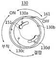
도 4에 도시된 바와 같이, 기능선택부(130)는 광원모듈(120)의 전원 온/오프 기능, 조명본체부(110)의 부착 기능 및 조명본체부(110)들 간의 결합 기능을 선택하는 역할을 한다.As shown in FIG. 4, the
기능선택부(130)는 조명본체부(110)에 구비되는데, 예를 들어, 기능선택부(130)는 원형 단면을 가지며 조명본체부(110)의 부착단(111)에 회전 가능하게 결합될 수 있다.The
또한, 기능선택부(130)는 조명본체부(110)와 결합되는 내측면에 광원모듈(120)의 온/오프 기능을 선택하는 온/오프 스위치단자(130a,130b)와, 조명본체부(110)의 부착 기능을 선택하는 부착 스위치단자(130c)와, 조명본체부(110)들 간의 결합 기능을 선택하는 결합 스위치단자(130d) 등이 구비될 수 있다. 이때, 온 스위치단자(130a), 오프 스위치단자(130b), 부착 스위치단자(130c) 및 결합 스위치단자(130d)는 기능선택부(130)의 회전 방향을 따라 90도 각도로 배치되는 것이 바람직하다. 여기서, 기능선택부(130)의 부착 기능을 선택한 후 조명본체부(110)를 금속재(1)에 자성을 통해 부착하는 경우에 후술하는 자성스위치부(140)는 광원모 듈(120)에 전원을 인가하게 된다. 또한, 기능선택부(130)의 결합 기능을 선택한 경우 제 1 및 제 2 광감지센서전극(161,163)에 전원이 인가 된다.In addition, the
또한, 기능선택부(130)에는 복수 개의 조명본체부(110)를 상호 결합할 수 있도록 연접하는 다른 조명본체부(110)의 결합돌기(153)가 삽입 결합될 수 있도록 후술하는 결합홈(151)이 한 쌍으로 형성될 수 있다.In addition, the
도 5는 조명장치에 구비되는 자성스위치부의 구조를 보여주는 절취도, 도 6 및 7은 자성스위치부의 동작을 설명하기 위한 예시도이다.5 is a cutaway view illustrating a structure of a magnetic switch unit provided in the lighting apparatus, and FIGS. 6 and 7 are exemplary views for explaining the operation of the magnetic switch unit.
도 5 내지 7에 도시된 바와 같이, 자성스위치부(140)는 조명본체부(110)를 차량의 외부 샤시, 건물의 철골 구조물 등과 같은 금속재(1)에 자성을 통한 부착과 동시에 광원모듈(120)에 전원을 인가하도록 스위칭하는 역할을 한다.As shown in FIGS. 5 to 7, the
자성스위치부(140)는 조명본체부(110)에 구비되며, 스위칭전극(141), 자성체(143) 및 탄성체(145) 등을 포함할 수 있다. 여기서, 스위칭전극(141)은 양(+)전극(141a)과 음(-)전극(141b)으로 구성되어 조명본체부(110)의 부착단(111) 내에 설치된 스위치홀더(115)에 내장되며, 광원모듈(120)에 전원을 인가하도록 스위칭한다. 또한, 자성체(143)는 조명본체부(110) 내 스위치홀더(115)에 수용되며, 금속재(1)와 자성을 통해 조명본체부(110)를 금속재(1)에 부착시킴과 동시에 스위칭전극(141)을 가압하여 통전시킨다. 여기서, 자성체(143)는 영구 자석(이하, 참조부호 143으로 설명함)인 것이 바람직하다. 또한, 탄성체(145)는 스위칭전극(141)과 자성체(143) 사이에 탄성을 제공하도록 구비될 수 있다. 여기서, 탄성체(145)는 원형링, 반원형링, 타원형링 등 다양한 형상을 가지는 플렉서블 기판(이하, 참조부호 145로 설명함)이고, 플렉서블 기판(145)의 상측면이 스위칭전극(141)의 상부전극, 예컨대 도 6 및 7의 양(+)전극(141a)에 고정되는 구조를 가지는 것이 바람직하다. 따라서, 조명장치(100)를 금속재(1)에 자성을 통해 부착하면 자성체(143)가 금속재(1)와 사이에 있는 탄성체(145)를 가압하여 스위칭전극(141)의 양(+)전극(141a)과 음(-)전극(141b)이 접촉되면서 광원모듈(120)에 전원이 인가되어 LED광원(123)이 발광하게 된다. 이때, 자성스위치부(140)는 기능선택부(130)의 부착 기능을 선택한 후 조명본체부(110)를 금속재(1)에 자성을 통해 부착하는 경우에 LED광원(123)에 전원을 인가하게 된다. 그리고, 조명장치(100)를 금속재(1)로부터 분리하면 자성체(143)와 금속재(1) 사이의 자력이 해제되고 탄성체(145)가 자성체(143)를 탄성 지지하면서 스위칭전극(141)의 양(+)전극(141a)과 음(-)전극(141b)이 이격되어 LED광원(123)에 공급되는 전원이 차단된다.The
본체결합부(150)는 조명본체부(110)가 복수 개로 마련되며, 각각의 조명본체부(110)를 상호 결합할 수 있도록 조명본체부(110)에 구비될 수 있다.The main
본체결합부(150)는 조명본체부(110)의 일단(111), 보다 상세하게는 조명본체부(110)의 일단(111)에 회전 가능하게 결합되는 기능선택부(130)에 형성되는 한 쌍의 결합홈(151)과, 조명본체부(110)의 타단(113)에 연접하는 다른 조명본체부(110)의 결합홈(151)들과 대응되게 형성되어 한 쌍의 결합홈(151)에 삽입 결합되는 한 쌍의 결합돌기(153)를 포함할 수 있다. 여기서, 한 쌍의 결합홈(151)은 기능선택부(130)의 단면에 중심을 기준으로 반경 방향으로 서로 대칭되게 이격 위치하는 한 쌍의 호형의 장공으로 구성될 수 있다. 또한, 한 쌍의 결합돌기(153)는 조명본체 부(110)의 타측 단면에 결합홈(151)과 대응되도록 중심을 기준으로 반경방향으로 서로 대칭되게 이격 위치하는 한 쌍의 돌기 형태로 구성될 수 있다.As long as the
도 8 내지 11은 조명장치의 결합구조를 설명하기 위한 예시도이다.8 to 11 are exemplary views for explaining the coupling structure of the lighting device.
먼저, 도 8에 도시된 바와 같이, 단위 조명 형태의 조명장치(100)들을 상호 결합하고자 할 경우, 어느 하나의 조명장치(100)의 일단에 형성된 한 쌍의 결합홈(151)과 연접한 다른 하나의 조명장치(100)의 타단에 형성된 한 쌍의 결합돌기(153)가 대응되도록 한다. 이때, 결합돌기(153)의 이탈방지용돌기 부분이 결합홈(151)의 삽입용홈 부분에 일치하도록 위치시킨다.First, as shown in FIG. 8, in the case where the
다음으로, 도 9에 도시된 바와 같이, 결합돌기(153)를 결합홈(151)에 삽입한다. 이때, 결합돌기(153)의 이탈방지용돌기 부분은 결합홈(151)의 삽입용홈 부분을 완전히 관통하게 된다.Next, as shown in FIG. 9, the
다음으로 도 10에 도시된 바와 같이, 결합돌기(153)를 결합홈(151)에 대하여 시계방향으로 회전시킨다.Next, as shown in FIG. 10, the
마지막으로, 도 11에 도시된 바와 같이, 결합돌기(153)가 결합홈(151)을 따라 끝까지 회전하면서 결합홈(151)과 결합돌기(153) 간의 체결이 이루어지게 됨에 따라 단위 조명 형태의 조명장치(100)들은 상호 결합될 수 있다.Finally, as shown in Figure 11, as the
도 12 내지 14는 조명장치의 결합 및 광 밝기 조절을 설명하기 위한 예시도이다.12 to 14 are exemplary views for explaining the coupling of the lighting device and the light brightness control.
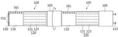
도 12 내지 14에 도시된 바와 같이, 휘도조절부(160)는 조명본체부(110)들 간의 상호 결합부위에 마련되며, 각각의 조명본체부(110)에 마련된 광원모듈(120) 의 광 밝기를 조절하는 역할을 한다.As shown in FIGS. 12 to 14, the
휘도조절부(160)는 제 1 광감지센서전극(161), 제 2 광감지센서전극(163) 및 광조절커버(165) 등을 포함할 수 있다. 여기서, 제 1 광감지센서전극(161)은 각각의 조명본체부(110)의 일단(111) 외주연에 조명본체부(110)의 길이방향으로 복수 개가 일정 간격을 두고 마련될 수 있다. 또한, 제 2 광감지센서전극(163)은 각각의 조명본체부(110)의 타단(113) 외주연에 조명본체부(110)의 길이방향으로 제 1 광감지센서전극(161)과 대응되게 복수 개가 일정 간격을 두고 마련될 수 있다. 또한, 광조절커버(165)는 조명본체부(110)들 간의 상호 결합부위의 외주연에 회전 가능하게 설치될 수 있다.The
광조절커버(165)는 조명본체부(110)들 간의 상호 결합부위의 외주연을 감싸도록 원통형상으로 형성되고 내주연에 암나사(165a)가 형성되어 조명본체부(110)의 타단(113) 외주연에 형성된 수나사(113a)와 나사 결합되며 나사 겹합에 따른 회전을 통해 제 1 광감지센서전극(161) 또는 제 2 광감지센서전극(163)쪽으로 이동하면서 제 1 및 제 2 광감지센서전극(161,163)을 작동시켜 각각의 조명본체부(110)에 마련된 광원모듈(120)의 광밝기를 동시에 조절할 수 있다. 이때, 기능선택부(130)의 결합 기능을 선택한 경우에만 제 1 및 제 2 광감지센서전극(161,163)에 전원이 인가된다.The
본 실시예에서는 광감지센서전극(161,163)을 사용하는 구성을 예시하였으나, 이에 한정되지 않고 광감지센서전극(161,163) 대신에 가변저항(미도시)을 사용하고 광조절커버(165)의 회전 조작을 통해 가변저항을 작동시켜 각각의 조명본체부(110) 에 마련된 LED광원(123)의 광밝기를 동시에 조절할 수도 있다.In the present embodiment, a configuration using the light
본 발명의 조명장치(100)는 복수 개의 조명본체부(110)와, 각각의 조명본체부(110)에 구비되는 광원모듈(120)과, 각각의 조명본체부(110)에 회전 가능하게 구비되며 광원모듈(120)의 전원 온/오프 기능, 조명본체부(110)의 부착 기능 및 조명본체부(110)들 간의 결합 기능을 선택하는 기능선택부(130)와, 각각의 조명본체부(110)에 내장되며 조명본체부(110)를 금속재(1)에 자성을 통한 부착과 동시에 광원모듈(120)에 전원을 인가하도록 스위칭하는 자성스위치부(140)와, 조명본체부(110)들을 상호 결합할 수 있도록 조명본체부(110)에 구비되는 본체결합부(150)와, 조명본체부(110)들 간의 상호 결합부위에 마련되어 각각의 조명본체부(110)에 마련된 광원모듈(120)의 광 밝기를 조절하는 휘도조절부(160) 등을 포함할 수 있다.The
상기와 같이 구성되는 조명장치(100)는 자석(143)을 내장하여 차량의 외부 샤시, 건물의 철골 구조물 등과 같은 금속재(1)와 같은 자석(143)이 붙는 곳에 부착하면 조명장치(100)의 LED광원(123)이 발광하는 장치로서, 동일한 형태의 조명장치(100)를 두 개 이상 결합하여 광 밝기를 동시에 조절할 수 있다.The
보다 상세하게는, 회전형 기능선택부(130)를 회전시켜 광원모듈(120)의 온/오프 스위칭 기능, 조명본체부(110)의 부착 스위칭 기능 및 조명본체부(110)들 간의 결합 스위칭 기능을 선택할 수 있다. 따라서, 본 발명의 조명장치(100)는 사용 목적에 따라 필요 시 다양한 형태의 기능을 가지는 조명장치로 사용할 수 있다.More specifically, the on / off switching function of the
또한, 기능선택부(130)의 부착 기능을 선택한 경우 자석(143)이 내장된 조명 장치(100)를 금속재(1)에 가져가면 자성을 통해 조명장치(100)가 금속재(1)에 부착됨과 동시에 전원 스위치가 온(ON)되어 조명장치(100)의 LED광원(123)에 전원이 공급되어 발광하게 된다. 따라서, 본 발명의 조정장치(100)는 야외 활동에서 휴대용 랜턴으로 사용 가능하며, 야간에 차량, 선박, 중장비, 건물 구조물 등에 부착하여 특수 목적용 랜턴 등 다양한 용도로 사용이 가능하다.In addition, when the attachment function of the
또한, 동일한 형태의 조명장치(100)를 두 개 이상 상호 결합하고 광감지센서 또는 가변저항을 이용하여 각각의 조명장치(100)에 구비된 LED광원(123)의 광 밝기를 동시에 조절할 수 있다. 따라서, 본 발명의 조명장치(100)는 독립적으로 하나 사용하는 경우 개별적인 광 밝기 조절이 가능하고 두 개 이상 결합하여 사용시 연동하여 각각의 LED광원(123)의 광 밝기를 동시에 조절할 수도 있다. 즉, 사용 목적에 따라 필요 시 단위 형태의 조명장치(100)를 두 개 이상 연결하여 사용 가능하며, 이 경우 각 조명장치(100)의 광 밝기 조절 기능이 싱크되어 동시에 광 밝기 조절이 가능하다.In addition, two or
이상 첨부된 도면을 참조하여 본 발명의 실시예를 설명하였지만, 본 발명이 속하는 기술분야에서 통상의 지식을 가진 자는 본 발명이 그 기술적 사상이나 필수적인 특징을 변경하지 않고서 다른 구체적인 형태로 실시될 수 있다는 것을 이해할 수 있을 것이다. 그러므로 이상에서 기술한 실시예들은 모든 면에서 예시적인 것이며 한정적이 아닌 것으로 이해해야만 한다. 본 발명의 범위는 상기 상세한 설명보다는 후술하는 특허청구범위에 의하여 나타내어지며, 특허청구범위의 의미 및 범위 그리고 그 균등 개념으로부터 도출되는 모든 변경 또는 변형된 형태가 본 발명의 범위에 포함되는 것으로 해석되어야 한다.Although the embodiments of the present invention have been described above with reference to the accompanying drawings, those skilled in the art to which the present invention pertains may implement the present invention in other specific forms without changing the technical spirit or essential features thereof. I can understand that. It is therefore to be understood that the above-described embodiments are illustrative in all aspects and not restrictive. The scope of the present invention is shown by the following claims rather than the above description, and all changes or modifications derived from the meaning and scope of the claims and their equivalents should be construed as being included in the scope of the present invention. do.
도 1은 본 발명의 일 실시예에 따른 조명장치의 개략도,1 is a schematic view of a lighting apparatus according to an embodiment of the present invention,
도 2 및 3은 도 1에서 하나의 단위 조명장치를 도시한 사시도,2 and 3 are perspective views showing one unit lighting apparatus in FIG.
도 4는 본 발명의 조명장치에 구비되는 기능선택부의 사시도,4 is a perspective view of a function selection unit provided in the lighting apparatus of the present invention;
도 5는 본 발명의 조명장치에 구비되는 자성스위치부의 구조를 보여주는 절취도,5 is a cutaway view showing the structure of the magnetic switch unit provided in the lighting apparatus of the present invention;
도 6 및 7은 자성스위치부의 동작을 설명하기 위한 예시도,6 and 7 are exemplary views for explaining the operation of the magnetic switch unit,
도 8 내지 11은 조명장치의 결합구조를 설명하기 위한 예시도,8 to 11 is an exemplary view for explaining a coupling structure of the lighting device,
도 12 내지 14는 조명장치의 결합 및 광 밝기 조절을 설명하기 위한 예시도이다.12 to 14 are exemplary views for explaining the coupling of the lighting device and the light brightness control.
< 도면의 주요 부분에 대한 부호의 설명 ><Description of Symbols for Main Parts of Drawings>
100 : 조명장치 110 : 조명본체부100: lighting device 110: lighting body
120 : 광원모듈 121 : 회로기판120: light source module 121: circuit board
123 : 광원, LED 130 : 기능선택부123: light source, LED 130: function selection
140 : 자성스위치부 141 : 스위칭전극140: magnetic switch unit 141: switching electrode
143 : 자성체, 자석 145 : 탄성체, 플렉서블기판143: magnetic body, magnet 145: elastic body, flexible substrate
150 : 본체결합부 151 : 결합홈150: body coupling portion 151: coupling groove
153 : 결합돌기 160 : 휘도조절부153: engaging projection 160: luminance control unit
161 : 제 1 광감지센서전극 163 : 제 2 광감지센서전극161: first photosensitive sensor electrode 163: second photosensitive sensor electrode
165 : 광조절커버165: light control cover
Claims (19)
Translated fromKoreanPriority Applications (1)
| Application Number | Priority Date | Filing Date | Title |
|---|---|---|---|
| KR1020090115974AKR101069990B1 (en) | 2009-11-27 | 2009-11-27 | Illumination apparatus |
Applications Claiming Priority (1)
| Application Number | Priority Date | Filing Date | Title |
|---|---|---|---|
| KR1020090115974AKR101069990B1 (en) | 2009-11-27 | 2009-11-27 | Illumination apparatus |
Publications (2)
| Publication Number | Publication Date |
|---|---|
| KR20110059290Atrue KR20110059290A (en) | 2011-06-02 |
| KR101069990B1 KR101069990B1 (en) | 2011-10-05 |
Family
ID=44394454
Family Applications (1)
| Application Number | Title | Priority Date | Filing Date |
|---|---|---|---|
| KR1020090115974AActiveKR101069990B1 (en) | 2009-11-27 | 2009-11-27 | Illumination apparatus |
Country Status (1)
| Country | Link |
|---|---|
| KR (1) | KR101069990B1 (en) |
Cited By (1)
| Publication number | Priority date | Publication date | Assignee | Title |
|---|---|---|---|---|
| WO2013125803A1 (en)* | 2012-02-22 | 2013-08-29 | Ryu Dae Young | Led lighting device and led lighting system having same |
Families Citing this family (1)
| Publication number | Priority date | Publication date | Assignee | Title |
|---|---|---|---|---|
| WO2013081273A1 (en)* | 2011-12-02 | 2013-06-06 | Kim Kyu-Wan | Removable led lighting apparatus and universal dc port |
- 2009
- 2009-11-27KRKR1020090115974Apatent/KR101069990B1/enactiveActive
Cited By (1)
| Publication number | Priority date | Publication date | Assignee | Title |
|---|---|---|---|---|
| WO2013125803A1 (en)* | 2012-02-22 | 2013-08-29 | Ryu Dae Young | Led lighting device and led lighting system having same |
Also Published As
| Publication number | Publication date |
|---|---|
| KR101069990B1 (en) | 2011-10-05 |
Similar Documents
| Publication | Publication Date | Title |
|---|---|---|
| KR101116509B1 (en) | Variable block type illumination apparatus | |
| CN102062377A (en) | Light emitting diode lamp | |
| UA96146C2 (en) | Improved scheme for portable flashlights and portable rechargeable electronic device | |
| JP3182543U (en) | lighting equipment | |
| KR100987460B1 (en) | Desk lamp with lantern function | |
| KR101249386B1 (en) | A led light with ac/dc convertor | |
| US9055642B2 (en) | Multi-purpose rechargeable LED lighting device | |
| KR20080005009U (en) | Housing for insertion lamps using LED | |
| US9458970B2 (en) | Lamp with LED light bulb | |
| KR101069990B1 (en) | Illumination apparatus | |
| US12429202B2 (en) | Lighting apparatus | |
| KR101192723B1 (en) | A portable lantern | |
| JP3154158U (en) | Omni-directional light bulb using light-emitting diode as light source | |
| US10907804B2 (en) | Lighting apparatus | |
| KR101529882B1 (en) | led illumination lamp | |
| JP3116268U (en) | Lamp unit | |
| KR20110001240U (en) | Radiation module | |
| KR101449618B1 (en) | led illumination lamp | |
| KR100970450B1 (en) | Portable illumination device with recharge able property | |
| JP3121905U (en) | Waterproof lighting equipment | |
| CN203628579U (en) | Head lamp | |
| JP3169673U (en) | LED lamp | |
| JP2013225450A (en) | Lighting device | |
| KR200350513Y1 (en) | Case of fluorescent light | |
| JP3083343U (en) | Light-emitting diode light-emitting device for fluorescent lighting equipment |
Legal Events
| Date | Code | Title | Description |
|---|---|---|---|
| A201 | Request for examination | ||
| PA0109 | Patent application | Patent event code:PA01091R01D Comment text:Patent Application Patent event date:20091127 | |
| PA0201 | Request for examination | ||
| E902 | Notification of reason for refusal | ||
| PE0902 | Notice of grounds for rejection | Comment text:Notification of reason for refusal Patent event date:20110422 Patent event code:PE09021S01D | |
| PG1501 | Laying open of application | ||
| E701 | Decision to grant or registration of patent right | ||
| PE0701 | Decision of registration | Patent event code:PE07011S01D Comment text:Decision to Grant Registration Patent event date:20110923 | |
| GRNT | Written decision to grant | ||
| PR0701 | Registration of establishment | Comment text:Registration of Establishment Patent event date:20110927 Patent event code:PR07011E01D | |
| PR1002 | Payment of registration fee | Payment date:20110927 End annual number:3 Start annual number:1 | |
| PG1601 | Publication of registration | ||
| FPAY | Annual fee payment | Payment date:20140829 Year of fee payment:4 | |
| PR1001 | Payment of annual fee | Payment date:20140829 Start annual number:4 End annual number:4 | |
| FPAY | Annual fee payment | Payment date:20150828 Year of fee payment:5 | |
| PR1001 | Payment of annual fee | Payment date:20150828 Start annual number:5 End annual number:5 | |
| FPAY | Annual fee payment | Payment date:20160906 Year of fee payment:6 | |
| PR1001 | Payment of annual fee | Payment date:20160906 Start annual number:6 End annual number:6 | |
| FPAY | Annual fee payment | Payment date:20170823 Year of fee payment:7 | |
| PR1001 | Payment of annual fee | Payment date:20170823 Start annual number:7 End annual number:7 | |
| FPAY | Annual fee payment | Payment date:20180828 Year of fee payment:8 | |
| PR1001 | Payment of annual fee | Payment date:20180828 Start annual number:8 End annual number:8 | |
| PR1001 | Payment of annual fee | Payment date:20200908 Start annual number:10 End annual number:10 | |
| PR1001 | Payment of annual fee | Payment date:20210126 Start annual number:11 End annual number:19 |