KR20110040233A - Modular Open Mobile Terminal Platform - Google Patents
Modular Open Mobile Terminal PlatformDownload PDFInfo
- Publication number
- KR20110040233A KR20110040233AKR1020090097419AKR20090097419AKR20110040233AKR 20110040233 AKR20110040233 AKR 20110040233AKR 1020090097419 AKR1020090097419 AKR 1020090097419AKR 20090097419 AKR20090097419 AKR 20090097419AKR 20110040233 AKR20110040233 AKR 20110040233A
- Authority
- KR
- South Korea
- Prior art keywords
- module
- board
- core
- power
- mobile terminal
- Prior art date
- Legal status (The legal status is an assumption and is not a legal conclusion. Google has not performed a legal analysis and makes no representation as to the accuracy of the status listed.)
- Withdrawn
Links
Images


Classifications
- G—PHYSICS
- G06—COMPUTING OR CALCULATING; COUNTING
- G06F—ELECTRIC DIGITAL DATA PROCESSING
- G06F1/00—Details not covered by groups G06F3/00 - G06F13/00 and G06F21/00
- G—PHYSICS
- G06—COMPUTING OR CALCULATING; COUNTING
- G06F—ELECTRIC DIGITAL DATA PROCESSING
- G06F13/00—Interconnection of, or transfer of information or other signals between, memories, input/output devices or central processing units
- G06F13/38—Information transfer, e.g. on bus
- G06F13/382—Information transfer, e.g. on bus using universal interface adapter
- G06F13/387—Information transfer, e.g. on bus using universal interface adapter for adaptation of different data processing systems to different peripheral devices, e.g. protocol converters for incompatible systems, open system
- G—PHYSICS
- G06—COMPUTING OR CALCULATING; COUNTING
- G06F—ELECTRIC DIGITAL DATA PROCESSING
- G06F13/00—Interconnection of, or transfer of information or other signals between, memories, input/output devices or central processing units
- G06F13/38—Information transfer, e.g. on bus
- G06F13/42—Bus transfer protocol, e.g. handshake; Synchronisation
- G06F13/4204—Bus transfer protocol, e.g. handshake; Synchronisation on a parallel bus
- G06F13/4234—Bus transfer protocol, e.g. handshake; Synchronisation on a parallel bus being a memory bus
Landscapes
- Engineering & Computer Science (AREA)
- Theoretical Computer Science (AREA)
- Physics & Mathematics (AREA)
- General Engineering & Computer Science (AREA)
- General Physics & Mathematics (AREA)
- Power Sources (AREA)
Abstract
Translated fromKoreanDescription
Translated fromKorean본 발명은 유무선 네트워크 융합서비스를 지원하는 모듈식 개방형 모바일 단말 플랫폼에 관한 것으로, 보다 상세하게는 유무선 네트워크(WCDMA, DMB, Wibro, WLAN, Bluetooth, Zibee 등)를 지원하고 용도에 따라 유무선 네트워크를 간편히 탈,부착할 수 있는 모듈식 개방형 모바일 단말 플랫폼에 관한 것이다.The present invention relates to a modular open mobile terminal platform that supports wired and wireless network convergence services, and more particularly, supports wired and wireless networks (WCDMA, DMB, Wibro, WLAN, Bluetooth, Zibee, etc.) and easily supports wired and wireless networks according to usage. The present invention relates to a modular open mobile terminal platform that can be attached and detached.
최근 이동통신 기술의 고속/대용량화, 가입자들의 편의성 추구, 데이터 통신에 대한 요구 증대 등으로 사업영역간 컨버전스(Convergence)가 진전되면서 휴대인터넷이 새로운 시장기회로서 부상하고 있다.Recently, as convergence between business areas is advanced due to high speed / capacity of mobile communication technology, pursuit of convenience for subscribers, and increasing demand for data communication, portable internet is emerging as a new market opportunity.
이러한 휴대인터넷의 관심이 증대되는 이유는 차세대 무선 기술로 떠오르고 있는 Wibro(Wireless Broadband), WCDMA(wideband code division multiple access)/HSDPA(high speed downlink packet access) 등과 같은 무선 서비스가 언제(Any time), 어디서나(Any where), 어떤 장비(Any device)로나 가능한 유비쿼터스 서비스 환경에 대한 요구뿐만 아니라 휴대인터넷을 통한 수익성 확보와 경쟁력을 강화하려는 통신서비스 업체의 투자환경 조성 등 수요와 공급 측면 모두 부합하고 있기 때문이다.The reason for the increased interest of the portable Internet is when wireless services such as wireless broadband (Wibro), wideband code division multiple access (WCDMA), and high speed downlink packet access (HSDPA) are emerging as next-generation wireless technologies. This is because it meets both the demand and supply aspects such as the demand for a ubiquitous service environment that can be used anywhere and any device, as well as the investment environment of a telecommunications service provider that wants to secure profitability and enhance competitiveness through the mobile Internet. to be.
현재 IP기술의 활성화에 따라 차세대 통신망(Wibro, WCDMA/HSPDA 등)은 IP 기반의 핵심망을 기반으로 하여 다양한 종류의 액세스 망을 수용하는 형태로 발전하고 있다.With the activation of IP technology, next-generation communication networks (Wibro, WCDMA / HSPDA, etc.) are evolving to accommodate various kinds of access networks based on IP-based core networks.
뿐만 아니라 액세스 망도 기존의 무선 LAN을 포함하여 IP기술을 기반으로 하는 액세스 망들이 점차 주류로 등장하고 있다.In addition, access networks based on IP technology, including existing wireless LANs, are gradually becoming mainstream.
이러한 차세대 망구조에서 이종망간의 핸드오버를 고려한 Media Independent Handover(MIH)기술을 바탕으로 한 이종망 융합 네트워크 지원 모바일 단말 플랫폼 기술 개발이 필수적이다.In this next-generation network structure, development of mobile terminal platform technology for heterogeneous network convergence network based on Media Independent Handover (MIH) technology considering handover between heterogeneous networks is essential.
또한 차세대 모바일단말에는 다양한 기능의 부가 모듈들이 첨가될 전망이고, 이에 따라 모바일 업체가 다양한 부가기능을 수용하는 모바일 단말 개발을 쉽게 진행할 수 있도록 하고 효과적으로 이용할 수 있는 차세대 모바일 단말 플랫폼 기술 개발이 필요하다.In addition, it is expected that additional modules with various functions will be added to the next generation mobile terminal. Accordingly, it is necessary to develop a next generation mobile terminal platform technology that enables a mobile company to easily develop a mobile terminal that accommodates various additional functions and effectively use it.
본 발명의 목적은 새로운 이종 망간 융합 서비스를 지원하는 개방적인 플랫폼을 개발함으로써 개발자와 사용자 모두의 편의성을 증가시키고, 새로운 서비스의 조기 정착이 가능하도록 하는 데 있다.An object of the present invention is to develop an open platform that supports a new heterogeneous manganese convergence service to increase the convenience of both developers and users, and to enable early settlement of new services.
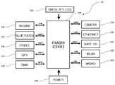
상기와 같은 목적을 달성하기 위한 본 발명의 특징은 다수의 커넥터가 구비되고, 메모리, 키패드가 접속되며 LCD 혹은 D-SUB, 콤포지트(COMPOSITE)단자를 통하여 텔레비젼이 접속된 보드와; 상기한 보드에 접속되고 SD CARD, KEYPAD INPUT/OUTPUT, UART, LCD CONTROLER, USB CLIENT, POWER MANAGEMENT를 포함하는 인터페이스를 제공하며 보드에 접속되는 각종 모듈들의 동작을 제어하고 윈도우계 운영체계 혹은 리눅스계 운영체계를 사용하는 코어와; 상기한 보드에 접속되고, 코어의 POWER MANAGEMENT 제어신호에 따라 코어를 포함한 다수 모듈의 동작에 필요한 전원을 출력하는 전원모듈; 상기한 보드의 커넥터와 대응되는 다른 커넥터가 구비되어 보드에 접속되고, 전원모듈의 구동 전원에 의하여 동작되어 코어의 제어신호에 의하여 동작이 제어되는 WCDMA모듈, 블루투스모듈, 지그비모듈, GPS모듈, WLAN모듈, 이더넷모듈, UART_SD모듈을 포함하는 것을 특징으로 하는 모듈식 개방형 모바일 단말 플랫폼에 있다.A feature of the present invention for achieving the above object is a board having a plurality of connectors, a memory, a keypad is connected and the TV is connected through the LCD or D-SUB, composite (COMPOSITE) terminal; It is connected to the above board and provides the interface including SD CARD, KEYPAD INPUT / OUTPUT, UART, LCD CONTROLER, USB CLIENT, POWER MANAGEMENT. It controls the operation of various modules connected to the board and operates the Windows system or Linux system. A core using the system; A power module connected to the board and outputting power required for operation of a plurality of modules including the core according to a power management control signal of the core; WCDMA module, Bluetooth module, ZigBee module, GPS module, WLAN, which is connected to the board is provided with a connector corresponding to the connector of the board, is operated by the driving power of the power module to control the operation by the control signal of the core The module is an open modular mobile terminal platform, characterized in that it comprises an Ethernet module, UART_SD module.
본 발명에 따른 개방형 모바일 단말 플랫폼은 모바일단말의 하드웨어와 소프 트웨어를 표준화, 모듈화시킴으로써 모바일단말 산업의 표준화 기술에 대하여 선진국에 비하여 기술 우위를 가질 수 있으며, 유비쿼터스 환경의 기반 플랫폼으로 모바일단말이 다양한 형태의 디바이스와 어플리케이션을 제공하는 중요한 역할을 할 수 있게 되어 유비쿼터스 환경의 중심기술로 활용될 수 있다The open mobile terminal platform according to the present invention can have a technological advantage over the developed countries in terms of standardization technology of the mobile terminal industry by standardizing and modularizing hardware and software of the mobile terminal, and have various forms of mobile terminals as a base platform of the ubiquitous environment. It can play an important role in providing devices and applications of the system and can be used as the core technology of the ubiquitous environment.
또한 하드웨어와 소프트웨어의 표준 플랫폼을 완성함으로써 중소기업 및 기술력이 다소 낮은 초기의 기업 상태에서 다양한 모바일기기들을 개발하는데 보다 적은 기술적인 노력과 연구개발 자금으로 개발하여 생산할 수 있게 된다.In addition, by completing the standard platform of hardware and software, it is possible to develop and produce with less technical effort and R & D fund to develop various mobile devices in the small and medium-sized enterprises and early companies with low technical skills.
이하, 본 발명의 바람직한 실시예를 첨부된 도면을 참조하여 상세히 설명한다.Hereinafter, exemplary embodiments of the present invention will be described in detail with reference to the accompanying drawings.
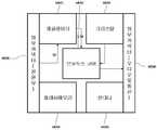
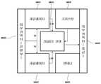
도 1a 내지 도 1c는 본 발명의 실시예에 따른 유무선 통합 개방형 플랫폼의 실시예를 나타내는 도면으로, 도 1a는 보드의 구성을 나타내는 도면이고, 도1b는 모듈이 접속된 상태의 보드 전면을 나타내고, 도 1c는 모듈이 접속되 상태의 보드 배면을 나타내는 도면이다.1a to 1c is a view showing an embodiment of a wired / wireless integrated open platform according to an embodiment of the present invention, Figure 1a is a view showing the configuration of the board, Figure 1b is a front view of the board connected to the module, 1C is a view showing the back of the board in the state that the module is connected.
그리고, 도 2 내지 도 8은 본 발명의 구성을 나타내는 블록도이다.2-8 is a block diagram which shows the structure of this invention.
본 발명의 실시예에 따른 유무선 통합 개방형 모바일 단말 플랫폼(10)은 다수의 커넥터가 구비되고, 메모리, 키패드가 접속되며 LCD 혹은 D-SUB, 콤포지트(COMPOSITE)단자를 통하여 텔레비젼이 접속된 보드(B)와; 상기한 보드에 접속되고 SD CARD, KEYPAD INPUT/OUTPUT, UART, LCD CONTROLER, USB CLIENT, POWER MANAGEMENT를 포함하는 인터페이스를 제공하며 보드에 접속되는 각종 모듈들의 동 작을 제어하고 윈도우계 운영체계 혹은 리눅스계 운영체계를 사용하는 코어(126)와; 상기한 보드에 접속되고, 코어의 POWER MANAGEMENT 제어신호에 따라 코어를 포함한 다수 모듈의 동작에 필요한 전원을 출력하는 전원모듈(124); 상기한 보드의 커넥터와 대응되는 다른 커넥터가 구비되어 보드에 접속되고, 전원모듈(124)의 구동 전원에 의하여 동작되어 코어(126)의 제어신호에 의하여 동작이 제어되는 WCDMA모듈(114), 블루투스모듈(115), 지그비모듈(116), GPS모듈(117), WLAN모듈(122), 이더넷모듈(120), UART_SD모듈(121)을 포함하여 구성되는데, 하기에서는 LCD가 연결된 것을 예로서 설명한다.Wired / wireless integrated open
상기에서 코어(126)인 PXA320보드는 SD CARD, KEYPAD INPUT/OUTPUT, UART, LCD CONTROLER, USB CLIENT, POWER MANAGEMENT 등 다양한 INTERFACE를 제공함으로써 다양한 기능들을 구성하게 되어 있다.The PXA320 board, which is the
전원모듈(124)의 메인 전원인 MAX8660(37)는 MAIN(21)전압 5V가 MAX8660(37)의 PV1~PV5 포트에 입력되면 V8(36)에 3.3V가 출력되며 RESET(26)과 PXA320(126)에 전원이 인가되면 EN1,EN2,EN5,EN34에서 3.3V 전압이 출력되면, V1(29) STEP-DOWN PWM Regulator 되서 3.3V, 최대1500mA를 출력하고 PXA320(126)의 MAIN전원으로 사용되며, V2(30)는 STEP-DOWN PWM Regulator되서 1.8V, 최대 900mA를 출력하며 DDR SDRAM MEMORY의 전원으로 사용되며, V3도 STEP-DOWN PWM Regulator 되서 1.4V, 1600mA를 출력되며 CORE POWER로 사용되며, V4는 STEP-DOWN PWM Regulator 되서 1.4V, 400mA를 출력되며 PXA320(126)의 SRAM의 POWER으로 사용되며, V5는 STEP-DOWN PWM Regulator 되서 1.8V, 200mA를 출력하고 INTERNAL PLL, VCC_OSC, INTERNEL LOGIC POWER로 사용되며, V6은 STEP-DOWN PWM Regulator 되서 1.4V, 500mA를 출력하고 사용되고 PXA320(126)의 SD_CARD의 DETECT VOLTAGE로 사용되며, V8은 STEP-DOWN PWM Regulator 되서 3.3V, 30mA를 출력하며 PXA320(126)의 부팅시 EN1,EN2,EN3,EN34에 3.3V를 출력하여 전체 전원을 공급하게 된다.The MAX8660 (37), the main power supply of the
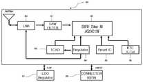
WCDMA(114)모듈은 USER SYSTEM(50)은 USB INTERFACE를 통해 PXA320과 연동하여 통신을 하며, SIM CON(55)는 SIM CARD를 통해 가입자를 인식하고 EAR_HF±(53), MIC_HF±(54)는 핸즈프리와 연결되어 통화를 가능하게 하며, ANTENA(56)는 주변에 있는 기지국을 감지하며 HAND OFF, 호처리 등을 하며 통신중에 원활한 동작을 위해 LDO(Low dropout regulator)(51)은500mA의 Regulator로 구성된다.The WCDMA 114 module communicates with the PXA320 through the USB INTERFACE, and the SIM CON 55 recognizes the subscriber through the SIM CARD, and the EAR_HF ± (53) and MIC_HF ± (54) ANTENA 56 detects base stations nearby, performs HAND OFF, call processing, etc., and LDO (Low dropout regulator) 51 is 500mA regulator for smooth operation during communication. It is composed.
BLUETOOTH(115)모듈은 브루투스 코어, 레귤레이터, 크리스탈, 플래시 메모리, 안테나 구성되며 브루투스 코어는 BC04-EXT규격을 따르고 외부 통신 인터페이스로 UART를 지원하며 오디오 입, 출력을 지원한다. 레귤레이터는 3.3V를 브루투스 코어에 알맞은 전압 1.5V로 바꾸어주는 역할을 하며, 크리스탈은 브루투스 코어의 동기를 제공하고 플래시 메모리는 외부메모리로써 프로그램메모리로 쓰여진다. PXA320(126)보드와 통신을 위해 외부 통신 인터페이스로는 UART를 사용한다. 안테나는 CHIP 안테나를 사용하여 보드의 공간 활용을 극대화 하게 구성 되었다.The BLUETOOTH 115 module consists of a brutus core, regulator, crystal, flash memory and antenna. The brutus core complies with the BC04-EXT standard, supports UART as an external communication interface and supports audio input and output. The regulator converts 3.3V to 1.5V suitable for the Brutus core. The crystal provides synchronization of the Brutus core and the flash memory is written to the program memory as external memory. UART is used as an external communication interface to communicate with the PXA320 (126) board. The antenna is configured to maximize the board's space utilization by using the CHIP antenna.
BLUETOOTH(115)모듈 외부커넥터는 각 모듈마다 80핀 커넥터 1쌍이 붙어 있으며 PXA320(126) 외부 커넥터(80핀 커넥터)와 BLUETOOTH(115)모듈과 연결되는 신호는 전원(5V), 오디오관련 신호, 외부 통신 신호(UART)가 있다. BLUETOOTH(115)모듈의 동작은 다음과 같다. PXA320(126) 외부 커넥터(80핀 커넥터)와 BLUETOOTH(115)모듈 외부 커넥터(M506)를 연결시킨다. POWER(124)보드에서 전원이 인가되면 외부커넥터(M500)으로 5V가 들어오게 되고 레귤레이터(M501)에서 5V를 3.3V로 전압을 낮추어서 블루투스 코어(M502)로 전원이 들어가게 된다. 이와 동시에 크리스탈(M503)은 블루투스 코어(M502)에 동기신호를 제공함으로써 블루투스 코어(M502)가 동작하게 된다. 블루투스 코어(M502)는 플래시 메모리(M504)에서 프로그램을 로딩하여 명령을 처리하게 되며 프로그램에 따라 안테나(M505)에서 들어오는 신호에 따라 적절히 처리하게 된다. 블루투스 코어(M502)에서 처리한 데이터는 BLUETOOTH(115)모듈 외부 커넥터(M506)로 PXA320(126)와 UART통신을 하게 된다.The BLUETOOTH (115) module external connector has a pair of 80-pin connectors for each module.The signals connected to the PXA320 (126) external connector (80-pin connector) and the BLUETOOTH (115) module are for power (5V), audio-related signals, and external. There is a communication signal (UART). The operation of the BLUETOOTH 115 module is as follows. Connect the PXA320 (126) external connector (80-pin connector) and the BLUETOOTH 115 module external connector (M506). When power is applied from the
ZIGBEE(116)모듈은 ZIGBEE코어, 레귤레이터, 외부크리스탈, 안테나, 외부 통신 인터페이스, ISP커넥터로 구성되며 ZIGBEE 코어는 ZIGBEE스택을 포함하고 있으며 레귤레이터는 5V를 ZIGBEE코어에 알맞은 전압 1.5V ZIGBEE 코어의 I/O에 알맞은 전압 3.0V로 바꾸어 주는 역할을 하며, 외부 크리스탈은 ZIGBEE의 동기를 제공하며 안테나는 CHIP 안테나를 사용하여 보드의 공간 활용을 극대화하게 구성 되었다. ISP커넥터를 통하여 ZIGBEE 프로그램을 다운로드 할 수가 있다. ZIGBEE(116)모듈의 외부커넥터는 각 모듈마다 80핀 커넥터 1쌍이 붙어 있으며 PXA320(126) 외부 커넥 터(80핀 커넥터)와 ZIGBEE(116)모듈과 연결되는 신호는 전원(5V)외부 통신 신호(UART)가 있다.ZIGBEE(116)모듈의 동작은 다음과 같다. PXA320(126) 외부 커넥터(80핀 커넥터)와 ZIGBEE(116)모듈의 외부 커넥터(M506)를 결합시킨다. POWER(124)보드에서 전원이 인가되면 외부커넥터(M600)으로 5V가 들어오게 되고 각 레귤레이터(M601,M602)에서 5V를 3.3V, 1.8로 전압을 나추어서 ZIGBEE 코어(M603)로 전원이 들어가게 된다. 이와 동시에 크리스탈(M504)은 ZIGBEE 코어(M603)에 동기신호를 제공함으로써 ZIGBEE 코어(M603)가 동작하게 된다. ZIGBEE 코어(M603)는 프로그램을 로딩하여 명령을 처리하게 되며 프로그램에 따라 안테나(M605)에서 들어오는 신호에 따라 적절히 처리하게 된다. ZIGBEE 코어(M603)에서 처리한 데이터는 ZIGBEE(116)모듈 외부 커넥터(M606)로 PXA320(126)와 UART통신을 하게 된다.ZIGBEE (116) module consists of ZIGBEE core, regulator, external crystal, antenna, external communication interface, ISP connector, ZIGBEE core includes ZIGBEE stack, regulator is 5V for ZIGBEE core, I / I of 1.5V ZIGBEE core The external crystal provides ZIGBEE synchronization, and the antenna is configured to maximize the board's space utilization by using CHIP antenna. You can download ZIGBEE program through ISP connector. The external connector of ZIGBEE (116) module has one pair of 80 pin connector for each module, and the signal connected to PXA320 (126) external connector (80 pin connector) and ZIGBEE (116) module is power (5V) external communication signal ( UART). The operation of the ZIGBEE 116 module is as follows. PXA320 126 external connector (80 pin connector) and ZIGBEE 116 module's external connector (M506) is combined. When power is applied from POWER (124) board, 5V is supplied to external connector (M600), and 5V is converted into 3.3V and 1.8 voltage from each regulator (M601, M602), and power is supplied to ZIGBEE core (M603). . At the same time, the crystal M504 provides a synchronization signal to the ZIGBEE core M603 so that the ZIGBEE core M603 operates. The ZIGBEE core M603 processes a command by loading a program and properly processes the signal according to the signal from the antenna M605 according to the program. Data processed by the ZIGBEE core (M603) is UART communication with the PXA320 (126) to the ZIGBEE (116) module external connector (M606).
GPS(117)모듈은 PXA320의 UART를 통해 경도, 위도 값을 연속적으로 전송하게 되며, 안정된 통신부를 구성하기 위해 다이폴 안테나를 사용 하였으며, 500mA의 LDO Regulator는 3.3V 전압을 모듈에 안정하게 공급하게 구성 되었다.GPS (117) module continuously transmits longitude and latitude values through UART of PXA320, and uses dipole antenna to form stable communication unit, and 500mA LDO Regulator is configured to stably supply 3.3V voltage to module. It became.
WLAN(122)모듈은 WLAN 코어(M803), 레귤레이터(M801,M802), 오실레이터(M804), 안테나(M805), 외부커넥터(M800,M806)로 구성되며 WLAN 코어(M803)는 IEEE802.11b/g스택을 포함하고 있으며 레귤레이터(M801,M802)는 5V를 ZIGBEE WLAN 코어(M803)에 알맞은 전압 3.3V(RF와IO용),1.8V(CORE와IO용) 바꾸어 주는 역할을 하며, 오실레이터(M804)는 WLAN 코어(M803)에 동기를 제공하며 안테나는 CHIP 안테 나를 사용하여 보드의 공간 활용을 극대화하게 구성 되었다.
WLAN(122)모듈의 외부 커넥터(M800,M806)는 각 모듈마다 80핀 커넥터 1쌍이 붙어 있으며 PXA320(126) 외부 커넥터(80핀 커넥터)와 WLAN(122)모듈과 연결되는 신호는 전원(5V)외부 통신 신호(USB)가 있다.The external connectors (M800, M806) of the
WLAN(122)모듈의 동작은 다음과 같다.The operation of the
PXA320(126) 외부 커넥터(80핀 커넥터)와 WLAN(122)모듈의 외부커넥터(M800,M806)를 결합시킨다. POWER(124)보드에서 전원이 인가되면 외부 커넥터(M800,M806)으로 5V가 들어오게 되고 각 레귤레이터(M801,M802)에서 5V를 3.3V, 1.8로 전압을 나추어서 WLAN 코어(M803)로 전원이 들어가게 된다. 이와 동시에 오실레이터(M804)은 WLAN 코어(M803)로에 동기신호를 제공함으로써 WLAN 코어(M803)가 동작하게 된다. WLAN 코어(M803)로는 프로그램을 로딩하여 명령을 처리하게 되며 프로그램에 따라 안테나(M805)에서 들어오는 신호에 따라 적절히 처리하게 된다. WLAN 코어(M803)에서 처리한 데이터는 WLAN(122)모듈 외부 커넥터(M806)로 PXA320(126)와 UART통신을 하게 된다.
PXA320에 사용가능한 USB는 한 개로 한정되어 있지만 여러 가지 디바이스를 사용할 수 있게 USB HUB를 구성하였으며 보다 안정된 전원 공급을 위해 MIC2027(Quad usb Power)로 구성되어있다.The USB available for the PXA320 is limited to one, but the USB HUB is configured to use multiple devices, and MIC2027 (Quad usb Power) is provided for more stable power supply.
DMB(118)모듈은 GPIO INTERFACE로 구성되어 있으며 PXA320으로부터 오디오 코덱을 열어 스피커로 오디오 신호를 출력함과 동시에 TFT-LCD화면에 영상을 출력하게 구성 된다.
CAMERA(119)모듈은 외부커넥터, 카메라 센서로 구성되며 CAMERA(119)모듈의 외부 커넥터는 양 옆으로 80핀 커넥터 1쌍이 붙어 있으며 PXA320(126)의 외부 커넥터(80핀 커넥터)와 CAMERA(119)모듈과 연결되는 신호는 전원(3.3V, 2.8V, 1.8V)과 데이터통신 라인, I2C통신 라인이 있다. CAMERA(119)모듈의 동작은 다음과 같다.The CAMERA (119) module consists of an external connector and a camera sensor.The external connector of the CAMERA (119) module has a pair of 80-pin connectors on both sides, and an external connector (80-pin connector) and CAMERA (119) of the PXA320 (126). Signals connected to the module include power supply (3.3V, 2.8V, 1.8V), data communication line and I2C communication line. The operation of the
PXA320(126) 외부 커넥터(80핀 커넥터)와 CAMERA(119)모듈의 외부커넥터를 결합시킨다. POWER(124)보드에서 전원이 인가되면 외부 커넥터로 3.3V, 2.8V, 1.8V가 들어오게 되고 카메라 센서가 동작하게 된다. PXA320(126) 외부 커넥터(80핀 커넥터)에서는 I2C 통신으로 카메라 센서로 커맨드를 주게 되면 카메라 센서에서 적절한 프로세싱을 거친 후의 데이터를 CAMERA(119)모듈의 외부 커넥터를 통하여 처리된 데이터를 PXA320(126)에 전송하게 된다.PXA320 (126) external connector (80 pin connector) is combined with external connector of CAMERA (119) module. When power is applied from POWER (124) board, 3.3V, 2.8V, 1.8V comes into external connector and camera sensor operates. In PXA320 (126) external connector (80-pin connector), if command is given to camera sensor through I2C communication, the data processed through the external connector of CAMERA (119) module is sent to PXA320 (126). Will be sent to.
ETHERNET(120), UART_SD(121)는 GPIO INTERFACE를 통해 PXA320의 외부에 연결되어 있는 NAND FLASH MEMORY에 접근하여 KERNEL, FILESYSTEM등 디버깅을 할 수 있게 구성되어 있다.ETHERNET (120), UART_SD (121) is configured to debug KERNEL, FILESYSTEM, etc. by accessing NAND FLASH MEMORY connected to the outside of PXA320 through GPIO INTERFACE.
한편, 상기한 코어는 NOR플래시 및 NAND플래시를 선택하여 부팅할 수 있고, 하이버네이션 및 웨이크업 기능이 있으며, 보드에는 조그다이얼 및 터치스크린이 더 구비되며,Meanwhile, the core may boot by selecting a NOR flash and a NAND flash, has a hibernation and wake-up function, and the board further includes a jog dial and a touch screen.
이와 같이 구성된 유무선 통합 개방형 모바일 단말 플랫폼은 다양한 전원을 안정적으로 공급할 수 있으며, 모듈 형태를 통해 USB, UART, GPIO 인터페이스등 다양한 인터페이스로 구현을 할 수 있는 하드웨어 장치로 구성되어 있다.The wired / wireless integrated open mobile terminal platform configured as described above can supply various power stably, and is composed of hardware devices that can be implemented in various interfaces such as USB, UART, and GPIO interfaces through a module form.
도 1a는 보드의 구성을 나타내는 도면1A is a diagram showing the configuration of a board
도 1b는 모듈이 접속된 상태의 보드 전면을 나타내는 도면Figure 1b is a view showing the front of the board with the module connected
도 1c는 모듈이 접속되 상태의 보드 배면을 나타내는 도면Figure 1c is a view showing the back of the board with the module connected
도 2는 본 발명의 실시예에 따른 유무선 통합 개방형 모바일 단말 플랫폼을 구성을 나타낸 블록도.Figure 2 is a block diagram showing the configuration of a wired / wireless integrated open mobile terminal platform according to an embodiment of the present invention.
도 3은 전원모듈을 나타내는 블록도3 is a block diagram showing a power module
도 4는 WCDMA모듈을 나타내는 블록도4 is a block diagram showing a WCDMA module
도 5는 블루투스모듈을 나타내는 블록도5 is a block diagram showing a Bluetooth module
도 6은 지그비모듈을 나타내는 블록도6 is a block diagram showing a Zigbee module
도 7은 GPS모듈을 나타내는 블록도7 is a block diagram showing a GPS module
도 8은 WLAN모듈을 나타내는 블록도8 is a block diagram showing a WLAN module
*도면의 주요부분에 대한 부호의 설명** Description of the symbols for the main parts of the drawings *
114 : WCDMA 115 : BLUETOOTH114: WCDMA 115: BLUETOOTH
116 : ZIGBEE 117 : GPS116: ZIGBEE 117: GPS
118 : DMB 119 : CAMERA118: DMB 119: CAMERA
120 : ETHERNET 121 : UART_SD120: ETHERNET 121: UART_SD
122 : WLAN 123 : WIBRO122: WLAN 123: WIBRO
124 : POWER 125 : 7INCH_TFT-LCD124: POWER 125: 7INCH_TFT-LCD
126 : PXA320126: PXA320
Claims (1)
Translated fromKoreanPriority Applications (1)
| Application Number | Priority Date | Filing Date | Title |
|---|---|---|---|
| KR1020090097419AKR20110040233A (en) | 2009-10-13 | 2009-10-13 | Modular Open Mobile Terminal Platform |
Applications Claiming Priority (1)
| Application Number | Priority Date | Filing Date | Title |
|---|---|---|---|
| KR1020090097419AKR20110040233A (en) | 2009-10-13 | 2009-10-13 | Modular Open Mobile Terminal Platform |
Publications (1)
| Publication Number | Publication Date |
|---|---|
| KR20110040233Atrue KR20110040233A (en) | 2011-04-20 |
Family
ID=44046634
Family Applications (1)
| Application Number | Title | Priority Date | Filing Date |
|---|---|---|---|
| KR1020090097419AWithdrawnKR20110040233A (en) | 2009-10-13 | 2009-10-13 | Modular Open Mobile Terminal Platform |
Country Status (1)
| Country | Link |
|---|---|
| KR (1) | KR20110040233A (en) |
- 2009
- 2009-10-13KRKR1020090097419Apatent/KR20110040233A/ennot_activeWithdrawn
Similar Documents
| Publication | Publication Date | Title |
|---|---|---|
| US8830889B2 (en) | Systems for remotely waking up application processor of mobile device | |
| KR101832953B1 (en) | Remote wakeup of application processor of mobile device | |
| CN106604369B (en) | Terminal equipment with dual-mode switching function | |
| US8937460B2 (en) | Dual-interface card reader module | |
| KR20090091343A (en) | Integrated Communication and Information Processing System | |
| CN101893926B (en) | Method, device and terminal for controlling switching of dual processor | |
| CN102448049B (en) | In portable terminal, detect the method and apparatus of the insertion of SIM | |
| US8386618B2 (en) | System and method for facilitating wireless communication during a pre-boot phase of a computing device | |
| KR101840287B1 (en) | Mobile device | |
| US8438408B2 (en) | Control of accessory components by portable computing device | |
| US8576758B2 (en) | Remote wake-up system, WWAM module and terminal | |
| JP2012518821A (en) | Wireless module built-in computer and its standby and recovery method | |
| EP3198363A2 (en) | Power management for memory accesses in a system-on-chip | |
| US20090172208A1 (en) | Wibro USB modem device having storage device | |
| CN102098390A (en) | Method for recovering subscriber identity module (SIM) of mobile phone in case of data transmission error and mobile phone | |
| US11758598B1 (en) | Automated multi-client and multi-mode wireless device pairing and connection methods and systems | |
| US20160309590A1 (en) | Apparatuses and methods for a multi pin-out smart card device | |
| CN100547600C (en) | A remote wake-up system and terminal based on WAN module | |
| CN103092304B (en) | Power supply control method of dual graphics card module and computer device using the method | |
| KR20110040234A (en) | Power Supply Unit of Mobile Terminal Platform | |
| CN103596300A (en) | Wireless router, wireless communication method and wireless communication system of local area network | |
| KR20110040233A (en) | Modular Open Mobile Terminal Platform | |
| KR20110040237A (en) | Board for Mobile Terminal Platform | |
| KR20110040236A (en) | Near field communication module platform | |
| CN101170420B (en) | Remote awaking system based on WWAN module, and WWAN module |
Legal Events
| Date | Code | Title | Description |
|---|---|---|---|
| PA0109 | Patent application | Patent event code:PA01091R01D Comment text:Patent Application Patent event date:20091013 | |
| PG1501 | Laying open of application | ||
| PC1203 | Withdrawal of no request for examination | ||
| WITN | Application deemed withdrawn, e.g. because no request for examination was filed or no examination fee was paid |