KR20110039327A - Radiation-emitting device - Google Patents
Radiation-emitting deviceDownload PDFInfo
- Publication number
- KR20110039327A KR20110039327AKR1020117002810AKR20117002810AKR20110039327AKR 20110039327 AKR20110039327 AKR 20110039327AKR 1020117002810 AKR1020117002810 AKR 1020117002810AKR 20117002810 AKR20117002810 AKR 20117002810AKR 20110039327 AKR20110039327 AKR 20110039327A
- Authority
- KR
- South Korea
- Prior art keywords
- radiation
- reflector
- opening
- wavelength converting
- emitting device
- Prior art date
- Legal status (The legal status is an assumption and is not a legal conclusion. Google has not performed a legal analysis and makes no representation as to the accuracy of the status listed.)
- Abandoned
Links
- 230000005855radiationEffects0.000claimsabstractdescription274
- 239000000463materialSubstances0.000claimsabstractdescription138
- 238000006243chemical reactionMethods0.000claimsabstractdescription26
- 239000004065semiconductorSubstances0.000claimsdescription21
- 238000000034methodMethods0.000claims13
- 239000010410layerSubstances0.000description23
- 230000003595spectral effectEffects0.000description22
- 230000005670electromagnetic radiationEffects0.000description18
- 230000008859changeEffects0.000description11
- 150000001875compoundsChemical class0.000description9
- 239000011159matrix materialSubstances0.000description9
- 239000000203mixtureSubstances0.000description6
- 239000002245particleSubstances0.000description6
- 230000009466transformationEffects0.000description5
- 230000002596correlated effectEffects0.000description4
- 230000007246mechanismEffects0.000description4
- -1corundumChemical class0.000description3
- 238000009826distributionMethods0.000description3
- 229910052751metalInorganic materials0.000description3
- 239000002184metalSubstances0.000description3
- 150000004767nitridesChemical class0.000description3
- 230000003287optical effectEffects0.000description3
- 239000004033plasticSubstances0.000description3
- 229920003023plasticPolymers0.000description3
- 239000007787solidSubstances0.000description3
- 238000001228spectrumMethods0.000description3
- 230000008901benefitEffects0.000description2
- ZYGHJZDHTFUPRJ-UHFFFAOYSA-NcoumarinChemical compoundC1=CC=C2OC(=O)C=CC2=C1ZYGHJZDHTFUPRJ-UHFFFAOYSA-N0.000description2
- 238000011161developmentMethods0.000description2
- 230000018109developmental processEffects0.000description2
- 239000011888foilSubstances0.000description2
- 230000036541healthEffects0.000description2
- 230000006698inductionEffects0.000description2
- 229920003229poly(methyl methacrylate)Polymers0.000description2
- 239000004926polymethyl methacrylateSubstances0.000description2
- 229910000980Aluminium gallium arsenideInorganic materials0.000description1
- GWEVSGVZZGPLCZ-UHFFFAOYSA-NTitan oxideChemical compoundO=[Ti]=OGWEVSGVZZGPLCZ-UHFFFAOYSA-N0.000description1
- 239000004904UV filterSubstances0.000description1
- 229910003363ZnMgOInorganic materials0.000description1
- 150000001252acrylic acid derivativesChemical class0.000description1
- 230000004913activationEffects0.000description1
- 230000006978adaptationEffects0.000description1
- 229910052784alkaline earth metalInorganic materials0.000description1
- 150000001336alkenesChemical class0.000description1
- 230000004075alterationEffects0.000description1
- 150000004645aluminatesChemical class0.000description1
- 229910052782aluminiumInorganic materials0.000description1
- XAGFODPZIPBFFR-UHFFFAOYSA-NaluminiumChemical compound[Al]XAGFODPZIPBFFR-UHFFFAOYSA-N0.000description1
- 230000004888barrier functionEffects0.000description1
- 229910052790berylliumInorganic materials0.000description1
- 229910052791calciumInorganic materials0.000description1
- 150000004649carbonic acid derivativesChemical class0.000description1
- 239000000919ceramicSubstances0.000description1
- 239000002800charge carrierSubstances0.000description1
- GTDCAOYDHVNFCP-UHFFFAOYSA-Nchloro(trihydroxy)silaneChemical classO[Si](O)(O)ClGTDCAOYDHVNFCP-UHFFFAOYSA-N0.000description1
- 238000005253claddingMethods0.000description1
- 239000002131composite materialSubstances0.000description1
- 229920001577copolymerPolymers0.000description1
- 239000010431corundumSubstances0.000description1
- 229910052593corundumInorganic materials0.000description1
- 229960000956coumarinDrugs0.000description1
- 235000001671coumarinNutrition0.000description1
- 230000007812deficiencyEffects0.000description1
- 238000009792diffusion processMethods0.000description1
- 238000003618dip coatingMethods0.000description1
- 239000002019doping agentSubstances0.000description1
- 238000000295emission spectrumMethods0.000description1
- 238000000407epitaxyMethods0.000description1
- 150000002118epoxidesChemical class0.000description1
- 239000003822epoxy resinSubstances0.000description1
- 239000011521glassSubstances0.000description1
- 230000005525hole transportEffects0.000description1
- 238000005286illuminationMethods0.000description1
- 238000003384imaging methodMethods0.000description1
- 150000003949imidesChemical class0.000description1
- 229910010272inorganic materialInorganic materials0.000description1
- 239000011147inorganic materialSubstances0.000description1
- 239000002346layers by functionSubstances0.000description1
- 238000004020luminiscence typeMethods0.000description1
- 229910052749magnesiumInorganic materials0.000description1
- 238000004519manufacturing processMethods0.000description1
- 230000000873masking effectEffects0.000description1
- 229910044991metal oxideInorganic materials0.000description1
- 150000004706metal oxidesChemical class0.000description1
- 239000000178monomerSubstances0.000description1
- 229910052605nesosilicateInorganic materials0.000description1
- 239000011022opalSubstances0.000description1
- 150000004762orthosilicatesChemical class0.000description1
- TWNQGVIAIRXVLR-UHFFFAOYSA-Noxo(oxoalumanyloxy)alumaneChemical compoundO=[Al]O[Al]=OTWNQGVIAIRXVLR-UHFFFAOYSA-N0.000description1
- 229910052760oxygenInorganic materials0.000description1
- 150000002979perylenesChemical class0.000description1
- 229920000647polyepoxidePolymers0.000description1
- 229920000642polymerPolymers0.000description1
- 229920001296polysiloxanePolymers0.000description1
- 238000003825pressingMethods0.000description1
- 239000011241protective layerSubstances0.000description1
- 229910052761rare earth metalInorganic materials0.000description1
- 229910052711seleniumInorganic materials0.000description1
- 229920002050silicone resinPolymers0.000description1
- 229910052709silverInorganic materials0.000description1
- 239000004332silverSubstances0.000description1
- 238000005507sprayingMethods0.000description1
- 229910052712strontiumInorganic materials0.000description1
- 229910052717sulfurInorganic materials0.000description1
- 239000010409thin filmSubstances0.000description1
- 150000003568thioethersChemical class0.000description1
- OGIDPMRJRNCKJF-UHFFFAOYSA-Ntitanium oxideInorganic materials[Ti]=OOGIDPMRJRNCKJF-UHFFFAOYSA-N0.000description1
- 230000001052transient effectEffects0.000description1
- LSGOVYNHVSXFFJ-UHFFFAOYSA-Nvanadate(3-)Chemical class[O-][V]([O-])([O-])=OLSGOVYNHVSXFFJ-UHFFFAOYSA-N0.000description1
- 238000013022ventingMethods0.000description1
Images


Classifications
- F—MECHANICAL ENGINEERING; LIGHTING; HEATING; WEAPONS; BLASTING
- F21—LIGHTING
- F21K—NON-ELECTRIC LIGHT SOURCES USING LUMINESCENCE; LIGHT SOURCES USING ELECTROCHEMILUMINESCENCE; LIGHT SOURCES USING CHARGES OF COMBUSTIBLE MATERIAL; LIGHT SOURCES USING SEMICONDUCTOR DEVICES AS LIGHT-GENERATING ELEMENTS; LIGHT SOURCES NOT OTHERWISE PROVIDED FOR
- F21K9/00—Light sources using semiconductor devices as light-generating elements, e.g. using light-emitting diodes [LED] or lasers
- F21K9/60—Optical arrangements integrated in the light source, e.g. for improving the colour rendering index or the light extraction
- F21K9/64—Optical arrangements integrated in the light source, e.g. for improving the colour rendering index or the light extraction using wavelength conversion means distinct or spaced from the light-generating element, e.g. a remote phosphor layer
- F—MECHANICAL ENGINEERING; LIGHTING; HEATING; WEAPONS; BLASTING
- F21—LIGHTING
- F21K—NON-ELECTRIC LIGHT SOURCES USING LUMINESCENCE; LIGHT SOURCES USING ELECTROCHEMILUMINESCENCE; LIGHT SOURCES USING CHARGES OF COMBUSTIBLE MATERIAL; LIGHT SOURCES USING SEMICONDUCTOR DEVICES AS LIGHT-GENERATING ELEMENTS; LIGHT SOURCES NOT OTHERWISE PROVIDED FOR
- F21K9/00—Light sources using semiconductor devices as light-generating elements, e.g. using light-emitting diodes [LED] or lasers
- F21K9/20—Light sources comprising attachment means
- F21K9/23—Retrofit light sources for lighting devices with a single fitting for each light source, e.g. for substitution of incandescent lamps with bayonet or threaded fittings
- F21K9/233—Retrofit light sources for lighting devices with a single fitting for each light source, e.g. for substitution of incandescent lamps with bayonet or threaded fittings specially adapted for generating a spot light distribution, e.g. for substitution of reflector lamps
- F—MECHANICAL ENGINEERING; LIGHTING; HEATING; WEAPONS; BLASTING
- F21—LIGHTING
- F21K—NON-ELECTRIC LIGHT SOURCES USING LUMINESCENCE; LIGHT SOURCES USING ELECTROCHEMILUMINESCENCE; LIGHT SOURCES USING CHARGES OF COMBUSTIBLE MATERIAL; LIGHT SOURCES USING SEMICONDUCTOR DEVICES AS LIGHT-GENERATING ELEMENTS; LIGHT SOURCES NOT OTHERWISE PROVIDED FOR
- F21K9/00—Light sources using semiconductor devices as light-generating elements, e.g. using light-emitting diodes [LED] or lasers
- F21K9/60—Optical arrangements integrated in the light source, e.g. for improving the colour rendering index or the light extraction
- F21K9/65—Optical arrangements integrated in the light source, e.g. for improving the colour rendering index or the light extraction specially adapted for changing the characteristics or the distribution of the light, e.g. by adjustment of parts
- F—MECHANICAL ENGINEERING; LIGHTING; HEATING; WEAPONS; BLASTING
- F21—LIGHTING
- F21V—FUNCTIONAL FEATURES OR DETAILS OF LIGHTING DEVICES OR SYSTEMS THEREOF; STRUCTURAL COMBINATIONS OF LIGHTING DEVICES WITH OTHER ARTICLES, NOT OTHERWISE PROVIDED FOR
- F21V14/00—Controlling the distribution of the light emitted by adjustment of elements
- F21V14/08—Controlling the distribution of the light emitted by adjustment of elements by movement of the screens or filters
- F—MECHANICAL ENGINEERING; LIGHTING; HEATING; WEAPONS; BLASTING
- F21—LIGHTING
- F21V—FUNCTIONAL FEATURES OR DETAILS OF LIGHTING DEVICES OR SYSTEMS THEREOF; STRUCTURAL COMBINATIONS OF LIGHTING DEVICES WITH OTHER ARTICLES, NOT OTHERWISE PROVIDED FOR
- F21V7/00—Reflectors for light sources
- F21V7/22—Reflectors for light sources characterised by materials, surface treatments or coatings, e.g. dichroic reflectors
- F21V7/24—Reflectors for light sources characterised by materials, surface treatments or coatings, e.g. dichroic reflectors characterised by the material
- F21V7/26—Reflectors for light sources characterised by materials, surface treatments or coatings, e.g. dichroic reflectors characterised by the material the material comprising photoluminescent substances
- F—MECHANICAL ENGINEERING; LIGHTING; HEATING; WEAPONS; BLASTING
- F21—LIGHTING
- F21V—FUNCTIONAL FEATURES OR DETAILS OF LIGHTING DEVICES OR SYSTEMS THEREOF; STRUCTURAL COMBINATIONS OF LIGHTING DEVICES WITH OTHER ARTICLES, NOT OTHERWISE PROVIDED FOR
- F21V7/00—Reflectors for light sources
- F21V7/22—Reflectors for light sources characterised by materials, surface treatments or coatings, e.g. dichroic reflectors
- F21V7/28—Reflectors for light sources characterised by materials, surface treatments or coatings, e.g. dichroic reflectors characterised by coatings
- F21V7/30—Reflectors for light sources characterised by materials, surface treatments or coatings, e.g. dichroic reflectors characterised by coatings the coatings comprising photoluminescent substances
- F—MECHANICAL ENGINEERING; LIGHTING; HEATING; WEAPONS; BLASTING
- F21—LIGHTING
- F21Y—INDEXING SCHEME ASSOCIATED WITH SUBCLASSES F21K, F21L, F21S and F21V, RELATING TO THE FORM OR THE KIND OF THE LIGHT SOURCES OR OF THE COLOUR OF THE LIGHT EMITTED
- F21Y2105/00—Planar light sources
- F21Y2105/10—Planar light sources comprising a two-dimensional array of point-like light-generating elements
- F—MECHANICAL ENGINEERING; LIGHTING; HEATING; WEAPONS; BLASTING
- F21—LIGHTING
- F21Y—INDEXING SCHEME ASSOCIATED WITH SUBCLASSES F21K, F21L, F21S and F21V, RELATING TO THE FORM OR THE KIND OF THE LIGHT SOURCES OR OF THE COLOUR OF THE LIGHT EMITTED
- F21Y2115/00—Light-generating elements of semiconductor light sources
- F21Y2115/10—Light-emitting diodes [LED]
- H—ELECTRICITY
- H10—SEMICONDUCTOR DEVICES; ELECTRIC SOLID-STATE DEVICES NOT OTHERWISE PROVIDED FOR
- H10H—INORGANIC LIGHT-EMITTING SEMICONDUCTOR DEVICES HAVING POTENTIAL BARRIERS
- H10H20/00—Individual inorganic light-emitting semiconductor devices having potential barriers, e.g. light-emitting diodes [LED]
- H10H20/80—Constructional details
- H10H20/85—Packages
- H10H20/851—Wavelength conversion means
Landscapes
- Engineering & Computer Science (AREA)
- General Engineering & Computer Science (AREA)
- Physics & Mathematics (AREA)
- Microelectronics & Electronic Packaging (AREA)
- Optics & Photonics (AREA)
- Non-Portable Lighting Devices Or Systems Thereof (AREA)
- Led Device Packages (AREA)
- Radiation-Therapy Devices (AREA)
Abstract
Translated fromKoreanDescription
Translated fromKorean본 발명은 청구범위 제1 항의 전문에 따른 방사선-방출 컴포넌트를 갖는 방사선-방출 장치에 관한 것이다.The present invention relates to a radiation-emitting device having a radiation-emitting component according to the preamble of
가변 컬러 또는 컬러 온도를 갖는 조명 장비의 경우에, 하나의 램프를 형성하도록 서로 다르게 컬러화된 개별 광원들을 조합할 수 있으며, 여기서 상기 개별 광원들의 광도는 개별적으로, 예컨대 전류를 변경함으로써 조정된다. 결과적으로, 상기 램프의 최종 다색 컬러는 가변적이다. 이로써, 그러나 정상 동작 동안, 모든 개별적인 광원들이 동시에 최대 광도로 조명되는 것은 아니다. 상기 램프에 의해 방출될 수 있는 원하는 광량을 획득하기 위해, 따라서, 원하는 광량을 위해 실제로 필요한 것보다 더 많은 개별적인 광원들을 이용할 필요가 있다. 더욱이, 상기 방출된 컬러 온도를 설정하도록 복잡한 전자 관리 시스템이 요구된다. 이는 이러한 종류의 램프가 복잡하며 비용-집중적임을 의미한다.In the case of lighting equipment having a variable color or color temperature, it is possible to combine differently colored individual light sources to form one lamp, wherein the brightness of the individual light sources is adjusted individually, for example by changing the current. As a result, the final multicolored color of the lamp is variable. As such, however, during normal operation, not all individual light sources are illuminated at full brightness simultaneously. In order to obtain the desired amount of light that can be emitted by the lamp, it is therefore necessary to use more individual light sources than are actually needed for the desired amount of light. Moreover, a complex electronic management system is required to set the emitted color temperature. This means that lamps of this kind are complex and cost-intensive.
또한 광원으로부터 광이 방사되고 이러한 방식으로 그 컬러를 변경하는 반투명 컬러 필터 포일들을 갖는 조명 장비가 공지되어 있다. 그러나, 결과적으로, 광은 필터링 아웃되고 상기 광원에 의해 달성가능한 최대 광도가 감소되며, 따라서 그와 같은 조명 장비의 효율성을 감소시켜 제조 및 동작 비용들이 증가한다.Also known is lighting equipment having translucent color filter foils which emit light from a light source and change its color in this way. As a result, however, the light is filtered out and the maximum luminous intensity achievable by the light source is reduced, thus reducing the efficiency of such lighting equipment, thereby increasing manufacturing and operating costs.
어떤 실시예들의 적어도 하나의 목적은 상술한 바와 같은 결함들을 회피하는 가변 전자기 2차 방사선을 방출하기 위한 방사선-방출 장치를 개시하는 것이다.At least one object of certain embodiments is to disclose a radiation-emitting device for emitting variable electromagnetic secondary radiation that avoids the deficiencies as described above.
상기 목적은 독립 청구항 제1 항의 특징들을 갖는 청구 대상에 의해 달성된다. 상기 청구 대상의 유용한 실시예들 및 추가적인 개발들은 독립 청구항들에서 특징화되고 또한 다음의 설명 및 도면들로부터 도출될 수 있다.This object is achieved by the subject matter having the features of
일 실시예에 따르면, 방출 방향으로 가변적인 전자기 2차 방사선을 방출하기 위한 방사선-방출 장치는 특히, 동작 동안, 전자기 1차 방사선을 방출하는 적어도 하나의 방사선-방출 컴포넌트, 상기 방사선-방출 컴포넌트의 빔 경로에 배열되고 전자기 변환 방사선으로의 1차 방사선의 적어도 부분적인 변환을 위한 제1 파장 변환 물질을 포함하는 반사기, 및 상기 방사선-방출 컴포넌트 및 반사기에 대해 그 배향의 관점에서 가변적인 개구를 포함하며, 여기서 상기 개구의 방향을 변경함으로써, 상기 제1 파장 변환 물질 상에 상기 방사선-방출 컴포넌트에 의해 방출되는 1차 방사선의 비율을 변경함으로써, 그리고 상기 방출된 변환 방사선을 변경함으로써 상기 2차 방사선은 가변적으로 된다.According to one embodiment, a radiation-emitting device for emitting electromagnetic secondary radiation which is variable in the emission direction is characterized by at least one radiation-emitting component which emits electromagnetic primary radiation, in particular during operation, of the radiation-emitting component. A reflector arranged in the beam path and comprising a first wavelength converting material for at least partial conversion of primary radiation to electromagnetic conversion radiation, and an aperture varying in terms of its orientation with respect to the radiation-emitting component and the reflector Wherein by changing the direction of the aperture, by changing the proportion of primary radiation emitted by the radiation-emitting component on the first wavelength converting material, and by changing the emitted converted radiation Becomes variable.
여기서 그리고 다음에서 일반적으로 "전자기 방사선", "전자기 1차 방사선", "전자기 2차 방사선" 및 "전자기 변환 방사선"은 특히 각각 자외선에서 적외선 파장 범위까지의 파장들을 갖는 전자기 방사선 또는 광을 설명한다. 이에 의해, 상기 변환 방사선 및 1차 방사선은 서로 상이하다. 이것은 특히 상기 1차 방사선이 관련된 강도들을 갖는 개별 파장들 또는 파장 범위들인 스펙트럼 컴포넌트들의 제1 스펙트럼 분포를 포함하고, 상기 변환 방사선이 제2 스펙트럼 분포를 포함하는 것을 의미하며, 여기서 상기 제1 및 제2 스펙트럼 분포는 적어도 하나의 파장에서 서로 상이하다. 이에 의해, 특히 상기 2차 방사선 및 상기 변환 방사선 및 또한 상기 1차 방사선은 가시적인 파장 범위로부터의 파장들을 포함할 수 있어 가시광일 수 있다. 특히 바람직하게는, 단색의, 다색 또는 백색의, 특히 관찰자 측에서의 광의 느낌인 차가운 백색 또는 따뜻한 백색을 환기시킬 수 있는 파장들 및 파장 범위들을 방출할 수 있다. 외부 관찰자에 의해 인식가능한 전자기 방사선의 광의 느낌은 예컨대, 당업자에게 익숙한 CIE-1931 표준 컬러 차트에서의 색도 좌표에 의해 특성화될 수 있다. 광의 백색 느낌은 또한 당업자에게 알려진 컬러 온도 및 상관된 컬러 온도에 의해 특성화될 수 있다.Here and in the following generally "electromagnetic radiation", "electromagnetic primary radiation", "electromagnetic secondary radiation" and "electromagnetic conversion radiation" describe in particular electromagnetic radiation or light, each having wavelengths in the ultraviolet to infrared wavelength range, respectively. . As a result, the converted radiation and the primary radiation are different from each other. This means in particular that the primary radiation comprises a first spectral distribution of spectral components that are individual wavelengths or wavelength ranges with associated intensities, wherein the converted radiation comprises a second spectral distribution, wherein the first and the first The two spectral distributions differ from each other at least one wavelength. Thereby, in particular the secondary radiation and the converted radiation and also the primary radiation may comprise wavelengths from the visible wavelength range and thus may be visible light. Particularly preferably, it is possible to emit wavelengths and wavelength ranges which are capable of venting monochromatic, multicolored or white, in particular cool white or warm white which is a feeling of light on the observer's side. The feeling of light of electromagnetic radiation recognizable by an external observer can be characterized, for example, by chromaticity coordinates in a CIE-1931 standard color chart that is familiar to those skilled in the art. The white feel of the light can also be characterized by the color temperature and correlated color temperature known to those skilled in the art.
여기서, 그리고 다음에서 전자기 방사선 또는 전자기 방사선의 비율에 대한 "변경"은 특히 상기 강도, 컬러, 컬러 온도 또는 그들의 조합에 대한 변경을 의미할 수 있다. 특히, 1차 방사선에 관하여, 상기 제1 파장 변환 물질 상에 상기 방사선-방출 컴포넌트에 의해 방출된 1차 방사선의 비율에 대한 변경은 상기 제1 파장 변환 물질 상에 방출된 1차 방사선의 전체 방사선 파워에 대한 변경을 의미할 수 있다. 여기서 그리고 다음에서, 변환 방사선의 변경은 특히 상기 방사선-방출 장치에 의해 방출된 변환 방사선의 방사선 파워의 변경 및/또는 상기 변환 방사선의 스펙트럼 구성의 변경을 의미할 수 있다.Here, and in the following, " change " to the electromagnetic radiation or to the proportion of the electromagnetic radiation can mean, in particular, a change to the intensity, color, color temperature or combination thereof. In particular, with respect to primary radiation, the change in the proportion of primary radiation emitted by the radiation-emitting component on the first wavelength converting material is the total radiation of the primary radiation emitted on the first wavelength converting material. It can mean a change to power. Here and in the following, the alteration of the converted radiation may in particular mean a change in the radiation power of the converted radiation emitted by the radiation-emitting device and / or a change in the spectral composition of the converted radiation.
여기서 그리고 다음에서, "반사기"는 전자기 방사선으로 조사될 때, 차례로 상기 조사된 전자기 방사선과 동일하거나 다를 수 있는 전자기 방사선을 방출하는 광학 컴포넌트를 나타낸다. 본 명세서에 설명된 방사선-방출 장치에서, 특히 1차 방사선은 상기 반사기상에 조사되며 변환 방사선 또는 부분적으로 변환되지 않은 1차 방사선과 함께인 변환 방사선은 상기 반사기에 의해 차례로 방출된다.Here and in the following, "reflector" denotes an optical component which, when irradiated with electromagnetic radiation, in turn emits electromagnetic radiation which may be the same or different from the irradiated electromagnetic radiation. In the radiation-emitting device described herein, in particular the primary radiation is irradiated on the reflector and the converted radiation, together with the converted radiation or the partially unconverted primary radiation, is in turn emitted by the reflector.
여기서 그리고 다음에서, "개구"는 입체각 범위 밖의 전자기 방사선을 마스킹하도록, 그리고 또한 상기 입체각 범위를 쉐이딩하도록 적합한 광학 컴포넌트를 표시한다. 상기 개구의 가변적인 배향은 또한 가변적인 쉐이딩가능한 입체각 범위에 의해 변동될 수 있다. 특히, 여기서 사용된 의미에서의 개구는 전자기 방사선에 투명하지 않으며 더욱이 반투명하지도 않다.Here and in the following, “opening” denotes an optical component suitable for masking electromagnetic radiation outside the solid angle range and also for shading the solid angle range. The variable orientation of the openings can also be varied by varying shadeable solid angle ranges. In particular, the openings in the sense used here are neither transparent nor electromagnetically transparent.
상기 개구가 상기 방사선-방출 컴포넌트 및 반사기에 대해 변동될 수 있다는 사실은 특히 단단하게 실장되는 반사기 및 방사선-방출 컴포넌트와 관련될 수 있다. 이는 상기 방사선-방출 장치가 상기 방사선-방출 장치의 영구적 실장 및/또는 재-탈부착가능한 고정을 위한 하우징 및/또는 엘리먼트를 포함하며, 상기 방사선 방출 컴포넌트 및 반사기가 상기 실장 및/또는 고정을 위한 하우징 및/또는 상기 엘리먼트에 고정 및 부동 방식으로 부착되는 것을 의미할 수 있다. 다른 한편, 상기 개구는 상기 실장 및/또는 고정을 위한 하우징 및/또는 엘리먼트에 대해 그 배향의 관점에서 가변적이다.The fact that the opening can vary with respect to the radiation-emitting component and the reflector can in particular relate to the rigidly mounted reflector and radiation-emitting component. This means that the radiation-emitting device comprises a housing and / or element for permanent mounting and / or re-detachable fixing of the radiation-emitting device, wherein the radiation emitting component and reflector are housings for mounting and / or fixing. And / or attached to the element in a fixed and floating manner. On the other hand, the opening is variable in terms of its orientation with respect to the housing and / or element for mounting and / or fastening.
본 명세서에 설명된 방사선-방출 장치는 상기 방사선-방출 컴포넌트 및 반사기에 대해 상기 개구의 배향에 대한 상대적인 변경에 의해, 방출된 2차 방사선, 예컨대 그의 강도, 컬러 온도 및/또는 색도 좌표의 조정 및 적응을 가능하게 할 수 있다. 이에 의해, 상기 방사선-방출 컴포넌트가 상기 방사선-방출 장치의 전자 동작 동안 변경되지 않은 동작 모드로 연속적으로 그리고 영구적으로 동작되게 할 수 있다. 결과적으로, 상기 방사선-방출 컴포넌트는 동작 동안 변경되지 않은 1차 방사선을 방출할 수 있는 한편, 상기 방사선-방출 장치에 의해 방출된 2차 방사선은 여전히 가변적이다. 상기 방사선-방출 컴포넌트의 변경되지 않은 동작 모드는 여기서 상기 1차 방사선이 그 강도 및 그 스펙트럼 범위에 관하여 변경되지 않은 채로 유지되는 것을 의미할 수 있다. 상기 방사선-방출 컴포넌트는 따라서, 예컨대 흐릿하지 않아야 한다. 그 결과, 상술한 바와 같은 방사선-방출 컴포넌트에 대한 전기적 공급을 위한 복잡한 관리 시스템이 상기 2차 방사선의 제어를 위해 전적으로 감소되거나 생략될 수 있다. 따라서, 상기 2차 방사선의 가변성이 상기 방사선-방출 컴포넌트의 동작 모드, 즉 예컨대 인가된 전압 또는 외부 전원(impressed current)과 같은 전기적 파라미터들 또는 온도에 대해 영향을 미치지 않을 수 있다.The radiation-emitting device described herein is adapted to adjust the emitted secondary radiation, such as its intensity, color temperature and / or chromaticity coordinates, by changing relative to the orientation of the opening with respect to the radiation-emitting component and reflector. Adaptation can be made possible. This allows the radiation-emitting component to be operated continuously and permanently in an unchanged mode of operation during the electronic operation of the radiation-emitting device. As a result, the radiation-emitting component can emit primary radiation unaltered during operation, while the secondary radiation emitted by the radiation-emitting device is still variable. The unchanged mode of operation of the radiation-emitting component may mean here that the primary radiation remains unchanged with respect to its intensity and its spectral range. The radiation-emitting component should therefore not be blurred, for example. As a result, a complex management system for the electrical supply to the radiation-emitting component as described above can be entirely reduced or omitted for the control of the secondary radiation. Thus, the variability of the secondary radiation may not affect the operating mode of the radiation-emitting component, ie electrical parameters or temperature, such as an applied voltage or an impressed current.
상기 2차 방사선은 상기 1차 방사선 및/또는 변환 방사선을 포함할 수 있으며, 그에 의해 상기 2차 방사선의 파라미터 강도, 색도 좌표인 컬러 및 컬러 온도 중 적어도 하나가 가변하도록 상기 2차 방사선이 가변될 수 있다. 이에 의해, 상기 2차 방사선은 특히 상기 방사선-방출 컴포넌트 및 상기 반사기에 대한 상기 개구의 배향에 의존하여, 상기 개구 배향에 의해 가변되는 상기 변환 방사선 및 또는 1차 방사선의 비율을 포함한다. 상기 1차 방사선의 가변 비율 및/또는 상기 2차 방사선의 변환 방사선의 가변 비율은 각각 최대값과 최소값 사이에서 가변될 수 있다. 상기 1차 방사선의 가변 비율의 최대 및 최소값은 상기 개구의 2개의 특정한, 서로 다른 배향들 사이에서 적용될 수 있다. 유사하게, 상기 제1 파장 변환 물질에 의해 방출되는 변환 방사선의 비율의 최대 및 최소값은 상기 개구의 2개의 특정 배향들에서 적용된다. 상기 최소값은 상기 1차 방사선 및/또는 상기 변환 방사선에 대해 제로와 다른 유한 방사선 파워 또는 제로의 방사선 파워를 의미할 수 있다. 이것은, 상기 개구의 어떤 배향에서, 상기 2차 방사선이 변환 방사선만을 포함하고 1차 방사선을 포함하지 않으며 및/또는 상기 개구의 어떤 다른 배향에서는 1차 방사선만을 포함하고 변환 방사선을 포함하지 않는 것을 의미할 수 있다. 상기 개구의 2개의 어떤 배향들 사이의 상기 개구의 배향을 연속적으로 변경함으로써, 상기 1차 방사선 및/또는 변환 방사선의 비율을 변경함으로써 상기 2차 방사선의 연속적인 변경을 달성할 수 있다.The secondary radiation may comprise the primary radiation and / or converted radiation, whereby the secondary radiation may be varied such that at least one of the parameter intensity of the secondary radiation, color and color temperature that are chromaticity coordinates, is variable. Can be. Thereby, the secondary radiation comprises a ratio of the converted radiation and / or the primary radiation which is varied by the aperture orientation, in particular depending on the orientation of the aperture with respect to the radiation-emitting component and the reflector. The variable ratio of the primary radiation and / or the variable ratio of the converted radiation of the secondary radiation may be varied between a maximum value and a minimum value, respectively. The maximum and minimum values of the variable ratio of the primary radiation can be applied between two specific, different orientations of the opening. Similarly, the maximum and minimum values of the ratio of converted radiation emitted by the first wavelength converting material are applied in two specific orientations of the opening. The minimum value may mean a finite radiation power different from zero or a radiation power of zero with respect to the primary radiation and / or the converted radiation. This means that in some orientations of the opening, the secondary radiation contains only converted radiation and does not contain primary radiation and / or contains only primary radiation in any other orientation of the opening and does not include converted radiation. can do. By continuously changing the orientation of the opening between two certain orientations of the opening, a continuous change of the secondary radiation can be achieved by changing the ratio of the primary radiation and / or converted radiation.
더욱이, 상기 방사선-방출 컴포넌트 및 반사기에 대한 개구의 배향에 따라, 상기 2차 방사선은 상기 개구 배향에 의해 가변될 수 있는 상기 변환 방사선의 스펙트럼 구성을 포함할 수 있다. 상기 변환 방사선의 스펙트럼 컴포넌트들의 전체인 상기 변환 방사선의 스펙트럼 구성은 가변하는 제1 스펙트럼과 제2 스펙트럼 사이에 상기 개구의 배향을 변경함으로써 가변될 수 있으며, 여기서 상기 제1 항 또는 제2 항에 있어서, 1 스펙트럼 및 제2 스펙트럼은 각각 상기 개구의 어떤 배향에 의해 환기될 수 있다.Moreover, depending on the orientation of the aperture relative to the radiation-emitting component and the reflector, the secondary radiation may comprise a spectral configuration of the converted radiation that may be varied by the aperture orientation. The spectral configuration of the transformed radiation, which is the entirety of the spectral components of the transformed radiation, can be varied by varying the orientation of the aperture between the varying first and second spectra, wherein the orientation of the opening is varied according to
예컨대, 상기 반사기는 상기 1차 방사선의 전자기 변환 방사선으로의 변환을 위해 제1 파장 변환 물질을 갖는 제1 서브-영역 및 제2 파장 변환 물질을 갖는 서브-영역을 포함할 수 있으며, 여기서 상기 제2 파장 변환 물질은 상기 제1 파장 변환 물질과 서로 상이하다. 이에 의해, 상기 제1 및 제2 서브-영역은 직접 서로 인접할 수 있다. 상기 제1 파장 변환 물질에 의해 방출되는 변환 방사선은 따라서, 상기 제2 파장 변환 물질에 의해 방출되는 변환 방사선과 다를 수 있다. 상기 반사기에 대해 상기 개구의 배향을 변경함으로써, 상기 제1 파장 변환 물질 상에 조사되는 1차 방사선의 비율 및 상기 제2 파장 변환 물질 상에 조사되는 2차 방사선의 비율의 비는 가변적일 수 있다. 그 결과, 상기 변환 방사선 및 또한 2차 방사선이 그들의 스펙트럼 구성에 관하여 가변적일 수 있도록, 상기 2차 방사선에 대한 상기 변환 방사선의 상기 제1 서브-영역에 의해 방출된 비율 및 상기 제2 서브-영역에 의해 방출된 비율이 서로에 대해 가변적일 수 있다.For example, the reflector may comprise a first sub-region with a first wavelength converting material and a sub-region with a second wavelength converting material for converting the primary radiation into electromagnetic converted radiation, wherein the first The two wavelength converting material is different from the first wavelength converting material. Thereby, the first and second sub-regions can be directly adjacent to each other. The converted radiation emitted by the first wavelength converting material may thus be different from the converted radiation emitted by the second wavelength converting material. By changing the orientation of the aperture with respect to the reflector, the ratio of the ratio of primary radiation irradiated on the first wavelength converting material and the ratio of secondary radiation irradiated on the second wavelength converting material may be variable. . As a result, the ratio emitted by the first sub-region of the converted radiation to the secondary radiation and the second sub-region such that the converted radiation and also the secondary radiation can be variable in terms of their spectral composition. The ratios released by can vary with respect to each other.
더욱이, 상기 반사기는 상기 제1 파장 변환 물질을 갖는 복수의 제1 서브-영역들 및 상기 제2 파장 변환 물질을 갖는 복수의 제2 서브-영역들을 포함할 수 있다. 이에 의해, 상기 제1 및 제2 서브-영역들은 나란히 교번하여 배열될 수 있다. 이에 의해, 상기 제1 및 제2 서브-영역들은 선형적으로, 즉 직선 또는 원호를 따라, 또는 2개 방향들을 따라, 즉 예컨대, 바둑판 모양 또는 매트릭스의 양식으로 배열될 수 있다. 더욱이, 상기 제1 및 제2 서브-영역들의 배열은 세그먼트들, 섹터들, 디스크들 또는 이들의 조합의 형태로 원형이거나 타원형일 수 있다.Furthermore, the reflector may include a plurality of first sub-regions having the first wavelength converting material and a plurality of second sub-regions having the second wavelength converting material. Thereby, the first and second sub-regions can be arranged side by side alternately. Thereby, the first and second sub-regions can be arranged linearly, ie along a straight line or arc, or along two directions, ie in the form of a checkerboard or matrix. Moreover, the arrangement of the first and second sub-regions may be circular or elliptical in the form of segments, sectors, disks or a combination thereof.
상기 반사기는 또한 상기 1차 방사선에 대해 부분적으로 반사할 수 있다. 이것은 상기 제1 및/또는 상기 제2 파장 변환 물질에 의해 변환되지 않고서, 상기 1차 방사선의 일부분이 상기 방사선-방출 장치의 방출 방향으로 상기 반사기에 의해 전환될 수 있음을 의미할 수 있다. 그 결과, 상기 반사기에 의해 방출된 전자기 방사선은 상기 변환 방사선 및 반사된 1차 방사선의 중첩으로부터 다색 광의 느낌을 줄 수 있다. 이를 위해, 상기 반사기는 예컨대, 상기 제1 또는 임의선택적으로 상기 제2 파장 변환 물질이 도포되는 반사 표면을 포함할 수 있다. 상기 반사 표면으로 인해, 변환되지 않은 형태로 상기 제1 파장 변환 물질 또는 임의선택적으로 상기 제2 파장 변환 물질을 가로지른 변환되지 않은 1차 방사선은 상기 변환 확률이 그 결과 효율적으로 증가될 수 있도록, 상기 제1 또는 제2 파장 변환 물질로 되돌려 반사될 수 있다.The reflector may also partially reflect the primary radiation. This may mean that a portion of the primary radiation can be diverted by the reflector in the direction of emission of the radiation-emitting device without being converted by the first and / or second wavelength converting material. As a result, the electromagnetic radiation emitted by the reflector can give a feeling of multicolored light from the superposition of the converted radiation and the reflected primary radiation. To this end, the reflector may comprise, for example, a reflective surface on which the first or optionally the second wavelength converting material is applied. Due to the reflective surface, the unconverted primary radiation in unconverted form or optionally across the second wavelength converting material may cause the conversion probability to be increased as a result of which, effectively It may be reflected back to the first or second wavelength conversion material.
예컨대, 상기 반사기 또는 그의 반사 표면은 거울같이 또는 확산적으로 반사할 수 있다. 거울 반사는 예컨대, 상기 반사기의 거울 표면에 의해 환기될 수 있다. "확산적 반사"는 특히 상기 반사기 상에 거울 같이 조사될 수 있는 1차 방사선이 상기 반사기에 의해, 비-화상 형성 방식으로 그리고 예컨대, 즉 서로 다른 방향들로 균일하게 등방성으로 반사될 수 있음을 의미할 수 있다. 이를 위해, 상기 반사 표면은 예컨대, 거칠게 될 수 있거나 반사 마이크로구조를 가질 수 있다.For example, the reflector or its reflective surface may reflect like mirrors or diffusely. Mirror reflections may be vented by, for example, the mirror surface of the reflector. “Diffuse reflection” is particularly understood that primary radiation, which can be irradiated like a mirror on the reflector, can be reflected by the reflector in a non-imaging manner and eg uniformly isotropic in different directions. Can mean. For this purpose, the reflective surface can be roughened or have a reflective microstructure, for example.
이에 대한 대안으로서, 상기 반사기는 변환 방사선만이 상기 방출 방향으로 유도되고 방출되도록 설계될 수 있다. 이를 위해, 상기 제1 파장 변환 물질 및/또는 임의선택적으로 상기 제2 파장 변환 물질은 상기 반사기 상에 조사된 모든 1차 방사선이 변환 방사선으로 변환되도록 구현될 수 있다. 대안적으로 또는 추가로, 상기 반사기는 상기 제1 및/또는―존재하는 경우― 상기 제2 파장 변환 물질이 도포되며 상기 1차 방사선을 흡수하는 표면을 포함할 수 있다. 이러한 종류의 실시예들은 상기 1차 방사선이 자외선 방사선 또는 적외선 방사선을 포함하거나 자외선 또는 적외선 방사선인 경우에 특히 유용할 수 있다. 이러한 종류의 방사선은 외부 관찰자에 의해 인식될 수 없으며, 자외선 방사선의 경우에, 예컨대 심지어 건강상의 이유들로 바람직하지 않을 수 있다.As an alternative to this, the reflector may be designed such that only converted radiation is directed and emitted in the emission direction. To this end, the first wavelength converting material and / or optionally the second wavelength converting material may be implemented such that all primary radiation irradiated on the reflector is converted into converted radiation. Alternatively or additionally, the reflector may comprise a surface to which the first and / or—if present—the second wavelength converting material is applied and absorbs the primary radiation. Embodiments of this kind may be particularly useful when the primary radiation comprises ultraviolet radiation or infrared radiation or is ultraviolet or infrared radiation. This kind of radiation cannot be recognized by an external observer and may be undesirable in the case of ultraviolet radiation, for example even for health reasons.
상기 반사기는 플라스틱, 금속, 세라믹 또는 그들의 조합들을 포함할 수 있거나 그러한 명칭의 재료들로 제조될 수 있다. 예컨대, 상기 반사기는 예컨대, 알루미늄 또는 은과 같은 금속으로 제조될 수 있거나, 적어도 금속으로 제조된 표면을 포함할 수 있다. 더욱이, 상기 반사기는 플라스틱, 특히 바람직하게는 백색의 플라스틱을 포함할 수 있다.The reflector may comprise plastic, metal, ceramic or combinations thereof or may be made of materials of that name. For example, the reflector may be made of metal, for example aluminum or silver, or may comprise at least a surface made of metal. Moreover, the reflector may comprise plastic, particularly preferably white plastic.
더욱이, 상기 반사기는 확산 입자들을 포함할 수 있다. 이에 의해, 상기 확산 입자들은 상기 반사기의 표면상에 배열될 수 있거나 매트릭스 재료로 상술한 바와 같은 파장 변환 물질과 함께 포함될 수 있거나 상기 반사기에 도포될 수 있다. 특히, 상기 확산 입자들은 예컨대, 금속 산화물, 예컨대 커런덤(corundum), 및/또는 유리 입자들과 같은 티타늄 산화물 또는 알루미늄 산화물을 포함할 수 있다. 이에 의해, 상기 확산 입자들은 10 마이크로미터의 규모 정도로 1 마이크로미터보다 작은 알갱이 크기들의 직경들을 가질 수 있다.Moreover, the reflector may comprise diffusing particles. Thereby, the diffusing particles may be arranged on the surface of the reflector or included with a wavelength converting material as described above in matrix material or applied to the reflector. In particular, the diffusing particles may comprise, for example, a metal oxide, such as corundum, and / or titanium oxide or aluminum oxide such as glass particles. Thereby, the diffusion particles may have diameters of grain sizes less than 1 micrometer on the scale of 10 micrometers.
상기 제1 파장 변환 물질 및/또는―존재하는 경우― 상기 제2 파장 변환 물질인 파장 변환 물질은 다음의 재료들: 예컨대, YAG:Ce3+, 질화물들, 질화 규산염들, 사이온들(sions), 시알론들(sialons), 알루민산염들, 산화물들, 할로포스페이트들(halophosphates), 오르토규산염(orthosilicates), 황화물들, 바나듐산염들(vanadates), 페릴린들(perylenes), 쿠마린(coumarin) 및 클로로실리케이트들(chlorosilicates)과 같은 희토류 알카리 토금속들의 가넷들(garnets) 중 하나 이상을 포함할 수 있다. 더욱이, 상기 파장 변환 물질은 또한 적합한 혼합물들 및/또는 그들의 조합들을 포함할 수 있다.The Ce3+, nitrides, the nitride-silicate, between one (sions: for example, YAG: said second wavelength converting material in the wavelength converting material has the following material, the first wavelength converting material and / or - if present ), Sialons, aluminates, oxides, halophosphates, orthosilicates, sulfides, vanadates, perylenes, coumarin ) And garnets of rare earth alkaline earth metals such as chlorosilicates. Moreover, the wavelength converting material may also comprise suitable mixtures and / or combinations thereof.
더욱이, 상기 파장 변환 물질은 상기 파장 변환 물질을 둘러싸거나 함유하거나, 상기 파장 변환 물질에 화학적으로 본딩되는 투명한 매트릭스 재료로 임베디드될 수 있다. 상기 투명 매트릭스 재료는 예컨대, 실리콘들, 에폭시드들, 아크릴산염들, 이미드화물, 탄산염들, 올레핀들(olefins) 또는 혼합물들, 공중합체들 또는 복합체들로서 모노머들, 올리고머들(oligomers) 또는 폴리머들의 형태로의 파생물들을 포함할 수 있다. 예컨대, 상기 매트릭스 재료는 에폭시 수지, 폴리메틸메타크릴레이트(polymethylmethacrylate)(PMMA) 또는 실리콘 수지일 수 있다.Furthermore, the wavelength converting material may be embedded in a transparent matrix material that surrounds or contains the wavelength converting material or is chemically bonded to the wavelength converting material. The transparent matrix material can be, for example, silicones, epoxides, acrylates, imides, carbonates, olefins or mixtures, copolymers or composites as monomers, oligomers or polymers. May include derivatives in the form of For example, the matrix material may be an epoxy resin, polymethylmethacrylate (PMMA) or silicone resin.
이에 의해, 상기 파장 변환 물질은 상기 매트릭스 재료에 균질하게 분포될 수 있다. 대안적으로 상술한 명칭들과 다른 재료들이 상기 매트릭스 재료의 서로 다른 층들 또는 구역들에 분포되고 배열될 수 있다.Thereby, the wavelength converting material may be homogeneously distributed in the matrix material. Alternatively, materials other than the above names may be distributed and arranged in different layers or zones of the matrix material.
이에 의해, 상기 파장 변환 물질은 상기 반사기에 직접 도포될 수 있다. 상기 파장 변환 물질 및/또는 상기 매트릭스 재료는 예컨대, 딥-코팅(dip-coating), 닥터링(doctoring), 페인팅-온에 의해, 또는 전기영동(electrophoretic) 처리에 의해 분사 또는 가압 처리에 의해 상기 반사기에 도포될 수 있다.Thereby, the wavelength converting material can be applied directly to the reflector. The wavelength converting material and / or the matrix material is, for example, by dip-coating, doctoring, painting-on, or by spraying or pressing by electrophoretic treatment. Can be applied to the reflector.
상기 파장 변환 물질은 상기 1차 방사선을 더 높은 파장을 갖는 변환 방사선으로 변환하도록 적합할 수 있다. 예컨대, 상기 1차 방사선은 황색 내지 적색 파장 범위의 스펙트럼 성분들을 갖는 변환 방사선으로 변환되는, 자외선 내지 녹색 파장 범위의 스펙트럼 성분들을 포함할 수 있다. 대안적으로 또는 추가로, 상기 파장 변환 물질은 또한 예컨대, 적외선 1차 방사선이 가시적인 변환 방사선으로 변환되도록, 주파수-혼합 및/또는 주파수-2배 속성들을 포함할 수 있다.The wavelength converting material may be suitable for converting the primary radiation into converted radiation having a higher wavelength. For example, the primary radiation may include spectral components in the ultraviolet to green wavelength range, which are converted to converted radiation having spectral components in the yellow to red wavelength range. Alternatively or in addition, the wavelength converting material may also include frequency-mixed and / or frequency-twice properties such that, for example, the infrared primary radiation is converted into visible converted radiation.
더욱이, 상기 개구는 또한 적어도 부분적으로 반사할 수 있다. 이에 의해, 상기 개구는 상기 반사기와 관련하여 상술한 특징들 중 하나 이상을 포함할 수 있다. 이하에 설명되는 상기 방사선-방출 컴포넌트 및 반사기에 대한 관계에서 상기 개구의 공간적 배열에 따르면, 상기 개구는 따라서, 상기 개구 상에 조사된 1차 방사선의 비율을 방출 방향으로 또는 상기 반사기의 방향으로 전환하도록 적합할 수 있다.Moreover, the opening can also reflect at least partially. Thereby, the opening may comprise one or more of the features described above in connection with the reflector. According to the spatial arrangement of the openings in relation to the radiation-emitting component and the reflector described below, the opening thus diverts the proportion of primary radiation irradiated onto the opening in the emission direction or in the direction of the reflector It may be suitable to.
상기 개구의 배향이 상기 방사선-방출 컴포넌트 및 상기 반사기에 대해 가변적이라는 사실의 결과로서, 상기 적어도 부분적으로 반사하는 개구에 의해 반사되는 상기 1차 방사선의 비율이 또한 변경될 수 있다. 상기 방사선-방출 컴포넌트 및 상기 반사기에 관한 상기 개구의 공간적 배열에 따르면, 따라서, 상기 2차 방사선에서 상기 1차 방사선의 비율 또는 상기 반사기 상에 조사되거나 전환된 상기 1차 방사선의 비율이 변경될 수 있으며, 이는 차례로 상기 2차 방사선의 변환 방사선의 비율이 변경될 수 있음을 의미한다.As a result of the fact that the orientation of the opening is variable with respect to the radiation-emitting component and the reflector, the proportion of the primary radiation reflected by the at least partially reflecting opening can also be varied. According to the spatial arrangement of the radiation-emitting component and the aperture with respect to the reflector, therefore, the ratio of the primary radiation in the secondary radiation or the ratio of the primary radiation irradiated or diverted on the reflector can be changed. This in turn means that the ratio of converted radiation of the secondary radiation can be changed.
더욱이, 상기 개구는 상기 제1 및―존재하는 경우―제2 파장 변환 물질과는 다른, 변환 방사선으로의 상기 1차 방사선의 적어도 부분적 변환을 위한 제3 파장 변환 물질을 포함할 수 있다. 이에 의해, 상기 제3 파장 변환 물질은 상기 제1 및 제2 파장 변환 물질과 관련하여 상술한 특징들 중 하나 이상을 포함할 수 있다. 따라서, 상기 반사기에 의해 방출된 1차 방사선 및/또는 변환 방사선에 더하여, 상기 2차 방사선은 또한 상기 개구에 의해 방출되는 변환 방사선을 포함할 수 있다.Moreover, the opening may comprise a third wavelength converting material for at least partial conversion of the primary radiation to converted radiation, different from the first and—if present—second wavelength converting materials. As such, the third wavelength converting material may include one or more of the features described above in connection with the first and second wavelength converting materials. Thus, in addition to the primary radiation and / or converted radiation emitted by the reflector, the secondary radiation may also include converted radiation emitted by the opening.
상기 개구의 배향이 상기 방사선-방출 컴포넌트 및 상기 반사기에 대해 가변적이라는 사실의 결과로서, 상기 개구 상에 조사된 상기 1차 방사선의 비율이 변경될 수 있다. 그 결과, 상기 제3 파장 변환 물질에 의해 변환 방사선으로 변환되는 상기 1차 방사선의 비율 및 상기 2차 방사선의 변환 방사선의 비율이 변경될 수 있다.As a result of the fact that the orientation of the opening is variable for the radiation-emitting component and the reflector, the ratio of the primary radiation irradiated on the opening can be changed. As a result, the ratio of the primary radiation converted to the conversion radiation by the third wavelength conversion material and the ratio of the conversion radiation of the secondary radiation can be changed.
상기 개구는 상기 반사기의 형상에 적응된 형상을 가질 수 있다. 이것은 상기 반사기가, 예컨대, 다각형 또는 둥근 형상 또는 그들의 조합을 갖는다는 것을 의미한다. 이를 위해, 상기 개구는 상기 반사기에 대한 상기 개구의 적어도 하나의 배향에서 적어도 일부분 또는 심지어 전체 반사기를 쉐이딩하도록 적합한 형상을 가질 수 있다. 이는 특히, 상기 개구가 상기 반사기와 유사한 또는 동일한 형상을 갖는다는 것을 의미할 수 있다. 예컨대, 상기 반사기 및 상기 개구는 각각 다른 하나의 최상부에 하나가 정렬될 수 있는 직사각형, 타원형 또는 원형 표면을 가질 수 있다. 상기 반사기 및 상기 개구에 관한 기하학적 표면 데이터는 유클리드의 또는 비-유클리드 기하학이라 지칭할 수 있다. 이것은 상기 반사기 및/또는 상기 개구의 영역 경계가 다각형 및/또는 둥근 형상을 가질 수 있으며 그에 의해 경계를 이루는 영역이 유클리드 기하학의 경우에 평탄하거나 비-유클리드 기하학의 경우에 만곡되어 있음을 의미할 수 있다. 예컨대, 상기 반사기 및/또는 상기 개구는 실린더 재킷의 일부분, 구형 쉘의 일부분, 회전 타원체, 회전 포물면 또는 회전 쌍곡면 또는 그들의 조합으로서 구현될 수 있다.The opening may have a shape adapted to the shape of the reflector. This means that the reflector has, for example, a polygonal or round shape or a combination thereof. To this end, the opening may have a shape suitable to shade at least part or even the entire reflector in at least one orientation of the opening with respect to the reflector. This may in particular mean that the opening has a shape similar or identical to the reflector. For example, the reflector and the opening may each have a rectangular, elliptical or circular surface that can be aligned one on top of the other. Geometric surface data regarding the reflector and the aperture may be referred to as Euclidean or non-Euclidean geometry. This may mean that the area boundary of the reflector and / or the opening may have a polygonal and / or round shape, whereby the boundary area is flat in the case of Euclidean geometry or curved in the case of non-Euclidean geometry. have. For example, the reflector and / or the opening may be embodied as part of a cylinder jacket, part of a spherical shell, ellipsoid, rotating parabolic surface or rotating hyperbolic surface, or a combination thereof.
상기 개구는 특히, 외부 관찰자에 의해 조망될 때, 상기 개구가 상기 반사기의 적어도 일부분을 커버하도록 상기 방사선-방출 컴포넌트 및 상기 반사기에 대해 적어도 하나의 배향으로 배열되고 구현될 수 있다. 상기 개구에 의해 커버된 반사기의 일부분은 상기 개구의 배향을 변경함으로써 변동될 수 있다. 특히, 이는 상기 방출 방향에 대해 상기 방사선-방출 장치의 반사기 및 개구를 바라보는 외부 관찰자에 의해 인식될 수 있다.The opening may be arranged and implemented in at least one orientation with respect to the radiation-emitting component and the reflector such that the opening covers at least a portion of the reflector, especially when viewed by an external observer. The portion of the reflector covered by the opening can be varied by changing the orientation of the opening. In particular, this can be recognized by an external observer looking at the reflector and opening of the radiation-emitting device with respect to the emission direction.
상기 개구는 더욱이 그 배향이 상기 방사선-방출 컴포넌트 및 상기 반사기에 대해 가변적인 적어도 하나의 구멍(opening)을 포함할 수 있다. 상기 구멍은 예컨대, 상기 반사기 상의 상기 제1 파장 변환 물질의 형상 및/또는―존재하는 경우― 상기 제2 파장 변환 물질의 형상에 적응된 형상을 가질 수 있다. 상기 제1 파장 변환 물질 또는 상기 제1 및 제2 파장 변환 물질들은 상기 반사기 상에 예컨대, 다각형, 예컨대 직사각형 또는 사각형, 또는 둥근, 예컨대 원형 또는 타원형 표면 영역 또는 그들의 조합을 가질 수 있다. 상기 구멍은 상기 반사기에 대한 상기 개구의 어떤 배향에서, 상기 제1 파장 변환 물질이 상기 반사기로부터 빗나가는 상기 개구의 측면으로부터 완전하게 또는 거의 완벽하게 가시적인 단면을 가질 수 있다. 상기 개구는 따라서, 다각형의, 예컨대 직사각형 또는 사각형의, 또는 둥근, 예컨대 원형 또는 타원형의, 단면 또는 그들의 조합을 가질 수 있다.The opening may further comprise at least one opening whose orientation is variable with respect to the radiation-emitting component and the reflector. The aperture may, for example, have a shape adapted to the shape of the first wavelength converting material on the reflector and / or the shape of the second wavelength converting material, if present. The first wavelength converting material or the first and second wavelength converting materials may have, for example, a polygon, such as a rectangle or square, or a round, such as a circular or elliptical surface area or a combination thereof on the reflector. The aperture may have a cross-section that is completely or nearly completely visible from the side of the opening at which the first wavelength converting material deviates from the reflector at any orientation of the opening with respect to the reflector. The opening may thus have a polygonal, eg rectangular or rectangular, or round, eg round or oval, cross section or combination thereof.
특히, 상기 반사기에 의해 방출된 상기 변환 방사선, 즉 상기 제1 및/또는―존재하는 경우―상기 제2 파장 변환 물질에 의해 생성되고 방출되는 변환 방사선의 적어도 일부분이 상기 방사선-방출 장치의 방출 방향으로 상기 구멍을 통해 방출될 수 있다.In particular, at least a portion of the converted radiation emitted by the reflector, i.e., the first and / or-if present,-converted radiation generated and emitted by the second wavelength converting material is the direction of emission of the radiation-emitting device Can be released through the hole.
더욱이, 상기 개구는 또한 복수의 구멍들을 가질 수 있다. 예컨대, 상기 반사기가 상술한 바와 같이 나란히 교번하여 배열된 제1 파장 변환 물질을 갖는 복수의 제1 서브-영역들 및 제2 파장 변환 물질을 갖는 복수의 제2 서브-영역들을 갖는 경우, 상기 개구는 상기 복수의 제1 및 제2 서브-영역들과 동일한 복수의 구멍들을 가질 수 있다. 상기 개구의 어떤 배향에서, 각 경우에, 상기 복수의 구멍들 중 하나는 상기 복수의 제1 서브-영역들에 걸쳐 배열될 수 있다. 결과적으로, 상기 방사선-방출 장치는 상기 복수의 구멍들을 통해 상기 제1 서브-영역들에서의 상기 제1 파장 변환 물질에 의해 생성되고 방출된 변환 방사선을 방출할 수 있다. 상기 개구의 추가적인 어떤 배향에서, 각 경우에 상기 복수의 구멍들 중 하나는 상기 복수의 제2 서브-영역들 중 하나 위에 배열될 수 있다. 그 결과, 상기 방사선-방출 장치는 상기 복수의 구멍들을 통해 상기 제2 서브-영역들에서의 상기 제2 파장 변환 물질에 의해 생성되고 방출된 변환 방사선을 방출할 수 있다. 이들 2개의 어떤 배향들 사이의 개구의 배향을 변경하는 것은 상기 2차 방사선이 상기 제1 파장 변환 물질 및 상기 제2 파장 변환 물질 둘 다에 의해 생성된 변환 방사선의 가변적인 비율들을 갖게 할 수 있다.Moreover, the opening may also have a plurality of holes. For example, when the reflector has a plurality of first sub-regions having a first wavelength converting material and a plurality of second sub-regions having a second wavelength converting material arranged side by side as described above, the opening May have the same plurality of holes as the plurality of first and second sub-regions. In any orientation of the opening, in each case one of the plurality of holes may be arranged over the plurality of first sub-regions. As a result, the radiation-emitting device may emit converted radiation generated and emitted by the first wavelength converting material in the first sub-regions through the plurality of holes. In some further orientation of the opening, in each case one of the plurality of holes may be arranged above one of the plurality of second sub-regions. As a result, the radiation-emitting device may emit converted radiation generated and emitted by the second wavelength converting material in the second sub-regions through the plurality of holes. Changing the orientation of the opening between these two certain orientations can cause the secondary radiation to have varying proportions of converted radiation produced by both the first wavelength converting material and the second wavelength converting material. .
상기 개구의 배향은 상기 방사선-방출 컴포넌트 및 상기 반사기에 대한 변환에 의해 변경될 수 있다. 이것은 특히, 상기 방사선 방출 컴포넌트 및 상기 반사기가 단단하게 실장되거나 고정될 수 있는 한편, 상기 개구는 그에 대해 이동될 수 있음을 의미한다. 이에 의해, 상기 변환은 예컨대, 직선을 따라 또는 곡선을 따라 발생할 수 있다. 예컨대, 상기 변환은 또한 원형 또는 타원형 변환 경로로 발생할 수 있다. 이를 위해, 상기 방사선-방출 장치는 상기 개구가 기계적으로 또는 전자기계적으로 이동될 수 있음에 의해, 예컨대, 유도 레일 또는 슬라이딩 메커니즘과 같은 유도 엘리먼트를 포함할 수 있다. 변환은 예컨대, 래스터에 의해 정의된 연속적인 이동 또는 이산적인 단계들에서의 이동을 포함할 수 있다.The orientation of the opening can be changed by the transformation for the radiation-emitting component and the reflector. This means, in particular, that the radiation emitting component and the reflector can be rigidly mounted or fixed while the opening can be moved relative thereto. Thereby, the transformation can occur, for example, along a straight line or along a curve. For example, the transformation can also occur with a circular or elliptic transformation path. For this purpose, the radiation-emitting device can comprise an induction element, for example an induction rail or a sliding mechanism, by which the opening can be moved mechanically or electromechanically. The transformation may comprise, for example, a continuous movement defined by a raster or a movement in discrete steps.
대안적으로 또는 추가로, 상기 2차 방사선은 상기 방사선-방출 컴포넌트 및 상기 반사기에 대한 상기 개구의 회전에 의해 변경될 수 있다. 이것은 상기 개구가 회전가능하며 상기 방사선-방출 컴포넌트 및 상기 반사기가 상기 환경에 대해 단단하게 그리고 부동으로 실장되는 것을 의미할 수 있다. 상기 개구는 예컨대, 상기 반사기의 연장 방향에 평행하거나 수직인 회전축에 관하여 상기 반사기에 대해 회전가능할 수 있다. 예컨대, 상기 회전축은 상기 개구가 상기 반사기의 연장 방향에 평행하게 선회될 수 있도록 상기 반사기의 연장 방향에 수직일 수 있다. 더욱이, 상기 개구는 상기 반사기에 대해 기계적으로 또는 전자기계적으로 기울어질 수 있도록 예컨대, 상기 반사기의 연장 방향에 평행한 회전축에 관하여 상기 반사기에 대해 회전가능할 수 있다. 이를 위해, 상기 방사선-방출 장치는 예컨대, 기계적 샤프트, 링크 또는 힌지와 같은 회전축을 갖는 회전, 선회(swiveling) 또는 폴딩 메커니즘과 같은 회전 엘리먼트를 포함할 수 있다.Alternatively or in addition, the secondary radiation can be altered by the rotation of the opening with respect to the radiation-emitting component and the reflector. This may mean that the opening is rotatable and the radiation-emitting component and the reflector are mounted firmly and floating relative to the environment. The opening can be rotatable relative to the reflector, for example with respect to a rotation axis parallel or perpendicular to the direction of extension of the reflector. For example, the axis of rotation may be perpendicular to the direction of extension of the reflector so that the opening can be pivoted parallel to the direction of extension of the reflector. Moreover, the opening may be rotatable relative to the reflector, for example about an axis of rotation parallel to the direction of extension of the reflector, such that it may be tilted mechanically or electromechanically with respect to the reflector. To this end, the radiation-emitting device may comprise a rotating element, for example a rotating, swiveling or folding mechanism having a rotational axis, such as a mechanical shaft, link or hinge.
회전은 예컨대, 래스터에 의해 정의된 연속적인 회전 또는이산 각 스텝들에서의 회전을 포함할 수 있다.Rotation can include, for example, continuous rotation or rotation indiscrete angular steps defined by a raster.
상기 2차 방사선의 조정성 및 가변성을 가능한 한 정확하게 달성하기 위해, 상기 방사선-방출 장치는 특히, 상술한 바와 같이, 상기 개구에 대해 적합한 정렬 장치를 갖는 제1 , 제2 및/또는 제3 파장 변환 물질들의 조합을 포함할 수 있다.In order to achieve as precisely as possible the tunability and variability of the secondary radiation, the radiation-emitting device has a first, second and / or third wavelength having a suitable alignment device for the aperture, in particular as described above. Combinations of conversion materials.
상술한 실시예들에서, 상기 개구는 상기 방사선-방출 컴포넌트와 상기 반사기 사이에 배열될 수 있다. 대안적으로, 상기 방사선-방출 컴포넌트는 또한 상기 개구와 상기 반사기 사이에 배열될 수 있다.In the above embodiments, the opening can be arranged between the radiation-emitting component and the reflector. Alternatively, the radiation-emitting component can also be arranged between the opening and the reflector.
상기 방사선-방출 컴포넌트는 점 모양의, 선형 또는 평탄한 방사선 소스로서 구현될 수 있다. 이에 의해, 특히 점 모양의 방사선 소스로서 구현된 방사선-방출 컴포넌트는 바람직하게는 직선에 평행한 일직선일 수 있을 뿐 아니라 구부러진 형태일 수 있다. 예컨대, 상기 방사선-방출 컴포넌트는 형광 램프, 특히 냉음극 형광 램프(CCFL), 열음극 형광 램프(CFL), 외부 전극 형광 램프(EEFL) 또는 평탄 형광 램프(FFL)를 포함할 수 있다. 대안적으로 또는 추가로, 상기 방사선-방출 컴포넌트는 전계발광 포일을 포함하거나 상기 포일일 수 있다. 더욱이, 상기 방사선-방출 컴포넌트는 발광 다이오드 또는 레이저 다이오드와 같은 방사선-방출 반도체 컴포넌트를 포함하거나 상기 컴포넌트일 수 있다. 이에 의해, 상기 방사선-방출 반도체 컴포넌트는 무기 또는 유기 발광 다이오드 또는 레이저 다이오드일 수 있다. 이에 의해, 또한 상기 방사선-방출 장치가 각각 동일하거나 다른 전자기 방사선을 방출하는 복수의 발광 다이오드들 또는 레이저 다이오드들을 포함하는 것이 유용할 수 있다.The radiation-emitting component may be implemented as a pointed, linear or flat radiation source. Thereby, the radiation-emitting component, in particular implemented as a point-shaped radiation source, can preferably be straight as well as parallel to a straight line, as well as in a curved form. For example, the radiation-emitting component may comprise a fluorescent lamp, in particular a cold cathode fluorescent lamp (CCFL), a hot cathode fluorescent lamp (CFL), an external electrode fluorescent lamp (EEFL) or a flat fluorescent lamp (FFL). Alternatively or in addition, the radiation-emitting component may comprise or be an electroluminescent foil. Moreover, the radiation-emitting component may comprise or be a radiation-emitting semiconductor component such as a light emitting diode or a laser diode. Thereby, the radiation-emitting semiconductor component can be an inorganic or organic light emitting diode or a laser diode. Thereby, it may also be useful for the radiation-emitting device to comprise a plurality of light emitting diodes or laser diodes, each emitting the same or different electromagnetic radiation.
무기 LED 또는 레이저 다이오드로서 구현된 방사선-방출 컴포넌트는 에피택셜 성장 반도체 층 시퀀스인 에피택시 층 시퀀스를 포함할 수 있다. 이에 의해, 상기 반도체 층 시퀀스는 예컨대, GaN 박막 반도체 칩들과 같이, 예컨대 InGaAlN의 무기 재료의 기반으로 구현될 수 있다. InGaAlN-기반 또는 질화물-기반 반도체 칩들은 특히, 일반적으로, 서로 다른 개별 층들의 층 시퀀스를 포함하는 에피택셜 생성 반도체 층 시퀀스가 상기 III-V족 화합물 반도체 재료 계통 InxAlyGai-x-yN으로부터의 재료를 포함하는 적어도 하나의 개별 층을 함유하는 것들을 포함하며, 여기서 0≤x≤1, 0≤y≤1 및 x+y≤1이다. 대안적으로 또는 추가로, 상기 반도체 층 시퀀스는 또한 상기 반도체 층 시퀀스가 서로 다른 개별 층들을 포함하고, 그 중 적어도 하나의 개별 층은 0≤x≤1, 0≤y≤1 및 x+y≤1인 경우에 상기 III-V족 화합물 반도체 재료 계통 InxAlyGai-x-yN으로 이루어진 재료를 포함하는 것을 의미하는 인화물-기반일 수 있는, InGaAlP에 기반할 수 있다. 대안적으로 또는 추가로, 상기 반도체 층 시퀀스는 또한 예컨대, AlGaAs-기반 재료, 또는 II-VI족 화합물 반도체 재료 계통들인 다른 III-V족 화합물 반도체 재료 계통들을 포함할 수 있다. II-VI족 화합물 반도체 재료 계통은 예컨대 Be, Mg, Ca, Sr과 같은 제2 메인 그룹으로부터의 적어도 하나의 원소 및 예컨대, O, S, Se와 같은 제 6 메인 그룹으로부터의 하나의 원소를 포함할 수 있다. 특히, II-VI족 화합물 반도체 재료 계통은 상기 제2 메인그룹으로부터의 적어도 하나의 원소 및 상기 제 6 메인 그룹으로부터의 적어도 하나의 원소를 포함하는 2원, 3원 또는 4기 화합물을 포함한다. 이러한 종류의 2원, 3원 또는 4기 화합물은 또한 예컨대, 하나 이상의 도펀트들 및 추가적인 성분들일 수 있다. 예컨대, 상기 II-VI 화합물 반도체 재료 계통들은 다음: ZnO, ZnMgO, CdS, ZnCdS, MgBeO를 포함한다.The radiation-emitting component implemented as an inorganic LED or laser diode may comprise an epitaxy layer sequence, which is an epitaxially grown semiconductor layer sequence. Thereby, the semiconductor layer sequence can be implemented on the basis of, for example, an inorganic material of InGaAlN, such as GaN thin film semiconductor chips. InGaAlN-based or nitride-based semiconductor chips, in particular, typically have an epitaxially produced semiconductor layer sequence comprising a layer sequence of different individual layers, wherein the III-V compound semiconductor material line Inx Aly Gai-x- and those containing at least one individual layer comprising a material fromy N, where 0 ≦ x ≦ 1, 0 ≦ y ≦ 1 and x + y ≦ 1. Alternatively or additionally, the semiconductor layer sequence also includes individual layers having different semiconductor layer sequences, wherein at least one individual layer is 0 ≦ x ≦ 1, 0 ≦ y ≦ 1 and x + y ≦. 1 may be based on InGaAlP, which may be phosphide-based, meaning that it includes a material consisting of the III-V compound semiconductor material line Inx Aly Gai-x-y N. Alternatively or additionally, the semiconductor layer sequence may also include other Group III-V compound semiconductor material systems that are, for example, AlGaAs-based material, or Group II-VI compound semiconductor material systems. Group II-VI compound semiconductor material systems include at least one element from a second main group such as, for example, Be, Mg, Ca, Sr and one element from the sixth main group, such as, for example, O, S, Se can do. In particular, the group II-VI compound semiconductor material system includes binary, tertiary or quaternary compounds comprising at least one element from the second main group and at least one element from the sixth main group. Binary, tertiary or quaternary compounds of this kind may also be, for example, one or more dopants and additional components. For example, the II-VI compound semiconductor material lines include: ZnO, ZnMgO, CdS, ZnCdS, MgBeO.
상기 반도체 층 시퀀스는 활성화 구역으로서, 예컨대 종래의 pn 접합, 이중 헤테로구조, 단일 퀀텀 웰(quantum well) 구조(SQW 구조) 또는 멀티-퀀텀 웰 구조(MQW 구조)를 포함할 수 있다. 상기 활성 구역에 더하여, 상기 반도체 층 시퀀스는 기능적 층들 및 기능적 구역들, 예컨대 전자 또는 홀 이송 층들인 p- 또는 n-도핑 전하 캐리어 이송 층들, p-, n 또는 비도핑 가둠(confinement) 또는 피복 층들, 장벽 층들, 평탄화 층들, 버퍼 층들, 보호 층들 및/또는 전극들 및 그들의 조합들을 더 포함할 수 있다. 상기 활성 구역 또는 상기 추가적인 기능적 층들 및 구역들에 관한 그와 같은 구조들은 특히 건축 구조, 기능 및 구조에 관하여 당업자에게 공지되어 있으므로, 본 명세서에서 더 설명되지 않을 것이다.The semiconductor layer sequence may include, for example, a conventional pn junction, a double heterostructure, a single quantum well structure (SQW structure) or a multi-quantum well structure (MQW structure) as an activation region. In addition to the active zone, the semiconductor layer sequence includes functional layers and functional zones, such as p- or n-doped charge carrier transport layers, p-, n or undoped confinement or cladding layers, which are electron or hole transport layers. Barrier layers, planarization layers, buffer layers, protective layers and / or electrodes and combinations thereof. Such structures with respect to the active zone or the additional functional floors and zones will not be described further herein, as they are known to those skilled in the art, in particular with respect to building structures, functions and structures.
예컨대, 상기 방사선-방출 컴포넌트는 자외선 스펙트럼 범위 및/또는 청색 스펙트럼 범위에서 전자기 1차 방사선을 방출할 수 있다. 이에 의해, 상기 1차 방사선은 예컨대, 365 나노미터로부터 예컨대, 490 나노미터의 범위에서의 하나 이상의 파장들을 포함할 수 있다.For example, the radiation-emitting component can emit electromagnetic primary radiation in the ultraviolet spectral range and / or in the blue spectral range. Thereby, the primary radiation may comprise one or more wavelengths, for example in the range of 365 nanometers, for example 490 nanometers.
본 명세서에 설명된 방사선-방출 장치로, 동작 동안 상기 방사선-방출 컴포넌트는 최적의 효율성으로 및/또는 형광 램프들 및 반도체 컴포넌트들 둘 다로, 높은 신뢰성 및 내구성을 가능하게 할 수 있는 완전한 광도로 불변이며 영구적으로 동작할 수 있다.With the radiation-emitting device described herein, during operation the radiation-emitting component is invariably at full brightness, which can enable high reliability and durability at optimum efficiency and / or with both fluorescent lamps and semiconductor components. It can operate permanently.
더욱이, 본 명세서에 설명된 방사선-방출 장치는 또한, 스위치-오프 동작 모드에서, 예컨대 실내 광 또는 실내의 컬러 온도에 가변적인 기여도를 만들도록 적합할 수 있다. 이를 위해, 상기 방사선-방출 장치는 실내에 설치될 수 있으며, 상기 제1 파장 변환 물질 및/또는―존재하는 경우―상기 제2 및/또는 제3 파장 변환 물질이 변환 방사선의 방출을 위해 실내의 주변 광, 예컨대, 태양 광에 의해 유도될 수 있다. 상술한 바와 같은 반사기에 대해 상기 개구의 배향을 변경함으로써, 상기 방사선-방출 장치의 스위치-온 동작 모드에서, 상기 변환 방사선이 가변적일 수 있으며, 이는 또한 스위치-오프 모드에서 방출될 수 있는 상기 변환 방사선의 형태에서의 상기 2차 방사선이 가변적일 수 있음을 의미한다.Moreover, the radiation-emitting device described herein may also be suitable to make variable contributions to a switch-off mode of operation, such as room light or color temperature of a room, for example. To this end, the radiation-emitting device can be installed indoors, wherein the first wavelength converting material and / or-if present-the second and / or third wavelength converting material is used in the room for the emission of converted radiation. It can be induced by ambient light, such as sunlight. By changing the orientation of the aperture with respect to the reflector as described above, in the switch-on mode of operation of the radiation-emitting device, the converted radiation can be variable, which is also the conversion that can be emitted in the switch-off mode. It means that the secondary radiation in the form of radiation can be variable.
본 발명의 추가적인 장점들 및 유용한 실시예들 및 추가적인 개발들은 도 1A 내지 도 5B를 참조하여 이하에 설명된 실시예들로부터 도출될 수 있다:Further advantages and useful embodiments and further developments of the present invention may be derived from the embodiments described below with reference to FIGS. 1A-5B:
도 1A 내지 1C는 예시적인 실시예에 따른 방사선-방출 장치의 개략 표현들이다.
도 2 내지 도 5B는 추가적인 예시적인 실시예들에 따른 방사선-방출 장치들의 개략적 표현들이다.1A-1C are schematic representations of a radiation-emitting device according to an exemplary embodiment.
2 to 5B are schematic representations of radiation-emitting devices according to further exemplary embodiments.
예시적인 실시예들 및 도면들에서, 동일한 컴포넌트들 또는 동일한 기능들을 갖는 컴포넌트들은 동일한 참조 숫자들에 의해 식별될 수 있다. 도시된 엘리먼트들 및 그 관련 크기들은 원칙적으로 실제 스케일로 취급되어서는 안 되고, 오히려 예컨대, 층들, 부분들, 컴포넌트들 및 구역들과 같은 개별적인 엘리먼트들은 더 우수한 표현성 및/또는 더 우수한 이해를 위해 과도하게 두껍거나 크게 도시될 수 있다.In example embodiments and the drawings, the same components or components having the same functions may be identified by the same reference numerals. The elements shown and their associated sizes should in principle not be treated on a real scale, but rather individual elements such as layers, parts, components and regions may be transient for better representation and / or better understanding. It can be shown thick or large.
명확성의 이유로, 여기서 그리고 다음에서의 예시적인 실시예들에서, 도시된 방사선-방출 장치들은 당업자에게 공지된 것으로 추정되는 하우징들, 기계적 유지 고정부들, 기계적 또는 전자기계적 시프팅 및/또는 회전 디바이스들이 없이, 그리고 전기 또는 전자 공급기 및/또는 제어 엘리먼트들 없이 도시된다. 모든 예시적인 실시예들에 공통인 것은 상기 반사기(2) 및 상기 방사선-방출 컴포넌트(들)(1)가 단단하게 실장되며 상기 개구(3)만이 상기 반사기(2) 및 방사선-방출 컴포넌트(들)(1)에 대해 그 배향의 관점에서 가변적이라는 것이다.For reasons of clarity, here and in the following exemplary embodiments, the radiation-emitting devices shown are housings, mechanical retaining fixtures, mechanical or electromechanical shifting and / or rotating devices which are believed to be known to those skilled in the art. And without electrical or electronic supplies and / or control elements. Common to all exemplary embodiments is that the
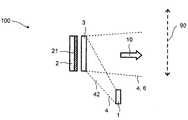
도 1A 내지 도 1C는 방사선-방출 장치(100)의 예시적인 실시예를 도시한다. 상기 방사선-방출 장치(100)는 동작 동안 전자기 1차 방사선(4)을 방출하는 방사선-방출 컴포넌트(1)를 포함한다. 도시된 상기 예시적인 실시예에서, 상기 방사선-방출 컴포넌트(1)는 청색 광의 느낌 및 예컨대, 365 내지 495 나노미터 범위의 파장을 갖는 스펙트럼 성분들을 갖는 1차 방사선(4)을 방출하는 무기의, 질화물-기반 레이저 다이오드를 포함한다.1A-1C show an exemplary embodiment of a radiation-emitting
상기 방사선-방출 컴포넌트(1)에서의 레이저 다이오드의 사용은 상기 1차 방사선(4)이 높은 강도로 그리고 낮은 발산으로의 콜리메이션(collimation)을 위해 적합한 빔으로 방출될 수 있게 한다. 높은 정도의 발광성을 요구하는 애플리케이션들에 대해, 상기 방사선-방출 컴포넌트(1)는 또한, 복수의 레이저 다이오드들, 예컨대 레이저 다이오드 바 또는 레이저 다이오드 어레이를 포함할 수 있다. 대안적으로, 상기 방사선-방출 컴포넌트(1)는 또한 예컨대, 하나 이상의 LED들 또는 형광 램프들을 포함할 수 있다. 더욱이, 상기 방사선-방출 컴포넌트(1)는 상술한 바와 같이, 명확성을 위해 도시되지 않은 1차 방사선(4)의 콜리메이션에 대한 하우징 및 광학 컴포넌트들을 포함한다.The use of a laser diode in the radiation-emitting
상기 1차 방사선(4)은 반사기(2) 상에 방출된다. 상기 반사기(2)는 확산적으로 반사하는, 상기 방사선-방출 컴포넌트(1)를 마주보는 백색 표면을 포함한다. 그 결과, 상기 반사기(2)는 그 파장에 관계없이, 전자기 방사선이 상기 반사기에 의해 원하는 방향이 없이 확산적으로 전환될 수 있도록 구현된다. 이를 위해, 상기 반사기(2)는 상기 방사선-방출 컴포넌트(1)를 마주보는 표면들 상에서 거칠게 된다. 대안적으로 또는 추가로, 상술한 바와 같이, 또한 산란 입자들이 상기 반사기(2)에 도포될 수 있다.The
상기 반사기(2)에 도포된 것은, 적어도 부분적으로 전자기 변환 방사선(5)으로 상기 1차 방사선을 변환할 수 있는 제1 파장 변환 물질(21)이다. 이를 위해, 상기 제1 파장 변환 물질(21)은 상기 반사기(2) 상에 배열되고, 투명 매트릭스 재료에 임베디드되는 전반 부분에서 상술한 재료들 중 하나 이상을 포함한다. 도시된 예시적인 실시예에서, 상기 제1 파장 변환 물질(21)에 의해 방출되는 상기 변환 방사선(5)은 황색 파장을 포함한다. 상기 제1 파장 변환 물질(21)의 구성 및 농도, 그리고 상기 제1 파장 변환 물질(21)이 상기 반사기(2)에 도포되는 두께는 상기 반사기(2)상에 조사된 상기 1차 방사선(4)이 변환 방사선(5)으로 변환되어 완료되도록 선택된다. 이에 의해, "완벽하게 변환된"이란 1/e 미만, 바람직하게는 1/e2 미만 및 특히 바람직하게는 상기 1차 방사선(4)의 1% 미만이 상기 제1 파장 변환 물질(21)을 갖는 반사기(2)에 의해 방출되는 것을 의미하며, 여기서 e는 오일러(Euler)의 수를 나타낸다. 특히 상기 1차 방사선(4)이 자외선 파장 범위로부터의 스펙트럼 성분들을 포함할 때, 건강상의 이유로, 예컨대, 외부 관찰자에 대해, 상기 반사기(2) 및 상기 방사선-방출 장치(100)에 의해 방출된 1차 방사선(4)의 비율이 가능한 한 낮게 되는 것이 유용하다.Applied to the
또한, 상기 방사선-방출 장치(100)는 상기 방사선-방출 컴포넌트(1) 및 상기 반사기(2)에 대해 그 배향의 관점에서 가변적인 개구(3)를 포함한다. 도시된 예시적인 실시예에서, 상기 개구(3)는 상기 방사선-방출 컴포넌트(1) 및 상기 반사기(2)에 대해, 2중 화살표(90)에 의해 표시되는 이동 방향 또는 변환 경로 상에서 이동될 수 있다. 이에 의해, 상대적인 배향에 따라, 상기 개구(3)가 상기 방사선-방출 컴포넌트(1)의 관점으로부터 상기 반사기(2)의 적어도 일 부분을 커버하고 쉐이딩할 수 있도록, 상기 개구(3)는 상기 반사기(2)와 상기 방사선-방출 컴포넌트(1) 사이에 배열된다. 상기 개구(3)의 배향을 변경하기 위해, 상기 방사선-방출 장치(100)는 예컨대, 명확성을 위해 도시되지 않은 레일과 같은 기계적 또는 전자기계적 이동 및/또는 슬라이딩 메커니즘을 포함한다. 대안적으로 또는 추가로, 상기 개구(3)는 또한 상기 방사선 방출 컴포넌트(1)와 상기 반사기(3)에 대해 회전가능할 수 있다. 이를 위해, 상기 방사선-방출 장치(100)는 예컨대, 회전 축, 힌지 및/또는 링크의 형태로 선회, 기울기 및/또는 회전 메커니즘을 포함할 수 있다.In addition, the radiation-emitting
도시된 예시적인 실시예에서, 상기 반사기와 같이, 상기 개구는 확산하여 반사하는, 상기 방사선-방출 컴포넌트(1)를 마주보는 백색 표면을 포함한다. 그 결과, 상기 파장에 관계없이, 상기 개구(3) 상에 조사되는 상기 1차 방사선(4)의 적어도 가시적 비율은 산란적으로 반사될 수 있다. 상기 1차 방사선(4)이 자외선 파장 범위로부터 적어도 하나의 스펙트럼 성분을 포함하는 경우, 가시광만이 상기 개구(3)에 의해 반사되도록 상기 개구(3)가 자외선 방사선을 흡수하는 것이 더욱 유용할 수 있다. 이를 위해, 상기 개구(3)는 예컨대, 상기 방사선-방출 컴포넌트(1)를 마주보는 표면상에 UV 필터층을 포함할 수 있다.In the exemplary embodiment shown, like the reflector, the opening comprises a white surface facing the radiation-emitting
도시된 실시예에서, 상기 반사기(2) 및 상기 개구(3)는 평탄한 설계를 갖는다. 대안적으로, 상기 반사기(2) 및/또는 상기 개구(3)는 또한 만곡되거나 구부러진 설계를 가질 수 있다. 특히 상기 반사기(2)는 예컨대, 거울 또는 확산 반사를 갖는 오목 거울의 형태로 설계될 수 있다. 이를 위해, 상기 반사기(2)는 공동 실린더, 공동 구, 회전 타원체, 회전 포물면, 회전 쌍곡면 또는 그들의 조합으로 구현될 수 있으며, 여기서 상기 방사선-방출 컴포넌트(1)와 마주보는 상기 제1 파장 변환 물질(21)을 갖는 상기 반사기(2)의 표면은 볼록 또는 오목 형태로 구현될 수 있다.In the embodiment shown, the
상기 방사선-방출 컴포넌트(1)의 동작 동안, 상기 방사선-방출 컴포넌트(1)는 상기 화살표(10)에 의해 표시된 방출 방향에서, 상기 개구(3)의 배향에 따라 상기 방사선-방출 컴포넌트(1) 및 상기 반사기(2)에 대해 가변적인 전자기 2차 방사선(6)을 방출한다. 도 1A 내지 도 1C는 상기 2차 방사선(6)의 가변성 및 조정성이 이하에서 순수하게 예시로서 설명되는 것을 참조하여, 상기 개구(3)의 3개의 서로 다른 배향들을 도시한다.During operation of the radiation-emitting
도 1A에서, 상기 개구(3)는 상기 반사기(2)에 대해 전체 1차 방사선(4)이 상기 제1 파장 변환 물질(21) 상에 조사되도록 제1 배향에 따라 배향된다. 따라서, 상기 제1 정렬에서, 상기 제1 파장 변환 물질(21)에 의해 변환 방사선(5)으로 변환될 수 있는 상기 1차 방사선(4)의 비율(41)은 상기 전체 1차 방사선(4)을 포함한다. 따라서, 도 1A에 따른 상기 제1 배향에서, 상기 방사선-방출 장치(100)는 2차 방사선(6)으로서 상기 변환 방사선(5)을 방출한다. 따라서, 상기 개구(3)의 제1 배향에서, 상기 2차 방사선(6)은 제로의 비율을 갖는 1차 방사선(4)을 포함한다.In FIG. 1A, the
도 1B는 상기 개구(3)가 상기 반사기(2) 및 또한 상기 제1 파장 변환 물질(21)을 완전히 쉐이딩하는, 상기 반사기(3)에 대한 제2 배향에서의 개구(3)를 도시한다. 따라서, 상기 개구(3) 상에 조사되는 1차 방사선(4)의 비율(42)은 전체 1차 방사선(4)을 포함하는 한편, 변환 방사선으로 변환된 상기 1차 방사선(4)의 비율은 도 1B에 따른 제2 배향에서 제로와 같다. 결과적으로, 상기 제2 배향에서, 상기 방사선-방출 장치(100)는 2차 방사선(6)으로서, 상술한 바와 같이 도시된 예시적인 실시예에서, 상기 1차 방사선(4)의 전체 가시적 비율일 수 있는, 상기 개구(3)에 의해 반사된 1차 방사선(4)을 방출한다.FIG. 1B shows the
도 1A에 따른 제1 배향과 도 1B에 따른 제2 배향 사이에서, 상기 개구(3)는 도 1C에 표시된 바와 같이 상기 이동 방향(90)을 따라 연속적으로 변경될 수 있다. 따라서, 상기 개구(3)는 상기 제1 및 제2 배향 사이에 있는 배향들을 채택할 수 있다. 도 1C에 따른 상기 개구(3)의 배향에서, 상기 개구(3)는 상기 1차 방사선(4)의 제1 비율(41)이 상기 제1 파장 변환 물질(21) 상에 조사되고 상기 1차 방사선(4)의 추가적인 제2 비율(42)이 상기 개구(3) 상에 조사되도록, 상기 반사기(2) 및 상기 제1 파장 변환 물질(21)을 부분적으로 쉐이딩한다. 따라서, 도 1C에 따른 상기 개구(3)의 배향에서, 상기 2차 방사선(6)은 상기 1차 파장 변환 물질(21)에 의해 방출되는 상기 가변적인 제1 비율(41) 및 상기 개구(3)에 의해 반사되는 상기 1차 방사선(4)의 제2 비율(42)을 통해 변동될 수 있는 가변적인 변환 방사선(5)을 포함한다.Between the first orientation according to FIG. 1A and the second orientation according to FIG. 1B, the
도 1C에서의 비율들(41 및 42)이 더 우수한 이해만을 위해 점선들로 표시되는 사실에 대한고속 참조가 이루어진다. 상기 1차 방사선(4)의 상기 제1 및 제2 비율들(41, 42)은 여기서 상기 방사선-방출 컴포넌트(1)의 설계 및 특히 상기 방사선-방출 컴포넌트(1)의 방사선 특성들에 의해 결정된다.Aquick reference is made to the fact that
특히, 상기 제1 파장 변환 물질(21)에 의해 방출된 변환 방사선(5) 및 상기 개구(3)에 의해 반사된 1차 방사선(4)은 상기 2차 방사선(6)이 동종의 중첩을 가질 수 있으며 상기 1차 방사선(4) 및 상기 변환 방사선(5)의 혼합물을 포함할 수 있도록 적어도 부분적으로 또는 심지어 동일하게 중첩될 수 있다.In particular, the converted radiation 5 emitted by the first
상기 제1 파장 변환 물질(21) 상에 상기 방사선-방출 컴포넌트(1)에 의해 방출되는 1차 방사선(4)의 제1 비율(41)을 변경함으로써, 그리고 상기 개구(3)의 배향을 변경하는 방식으로 상기 방출된 변환 방사선(5)을 변경함으로써 상기 2차 방사선(6)은 가변적이다. 이에 의해, 도시된 예시적인 실시예에서, 상기 2차 방사선(6)의 광 느낌은 청색과 황색 사이에서 연속적으로 변동할 수 있다. 특히, 도 1C에 따른 상기 개구(3)의 배향들에서, 상기 2차 방사선(6)은 상기 청색 1차 방사선(4) 및 상기 황색 변환 방사선(5)을 중첩함으로써 가변적인 컬러 온도 또는 가변적인 상관된 컬러 온도를 갖는 백색 광 느낌을 환기시킬 수 있다.By changing the
상기 방사선-방출 컴포넌트(1)로서 하나 이상의 청색 LED들 또는 레이저 다이오드들을 이용할 때 특히, 상기 방사선-방출 컴포넌트(들)(1)가 완전한 광도로 동작할 수 있으며 상기 2차 방사선(6)의 광 느낌의 컬러가 여전히 상기 개구(3)에 의해 조정될 수 있기 때문에, 가변적인 컬러 방사선을 갖는 공지된 조명 시스템에 비해 상기 방사선-방출 장치(100)에 대한 상당한 비용 장점이 존재한다. 더욱이, 심지어 복수의 방사선-방출 컴포넌트들(1)로, 하나의 1차 방사선(4)만이 사용되기 때문에, 복잡한 컬러 관리 시스템이 회피되며 따라서 비용절약된다.When using one or more blue LEDs or laser diodes as the radiation-emitting
다음의 도면들은 도 1A 내지 도 1C에 따른 예시적인 실시예들의 방사선-방출 장치(100)의 변형들 및/또는 확장들을 포함하는 방사선-방출 장치들의 예시적인 실시예들을 도시한다. 따라서, 다음의 설명은 주로 상기 방사선-방출 장치(100)에 비교되는 차이들을 언급한다.The following figures show exemplary embodiments of radiation-emitting devices that include variations and / or extensions of the radiation-emitting
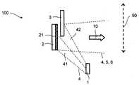
도 2는 상기 방사선 방출 장치(100)의 변형을 나타내는 방사선-방출 장치(200)의 예시적인 실시예를 도시한다. 이전의 예시적인 실시예들과 비교하여, 상기 방사선-방출 컴포넌트(1)는 상기 1차 방사선이 예컨대, 465 내지 480 나노미터 사이의 파장을 갖는 스펙트럼 성분들을 갖는 청색 광만을 포함하도록 설계된다.2 shows an exemplary embodiment of a radiation-emitting
상기 반사기(2) 및 상기 제1 파장 변환 물질(21)은 상기 반사기(2) 및 상기 제1 파장 변환 물질(21) 상에 조사된 상기 1차 방사선(4)의 제1 비율(41)이 황색 파장 범위에서의 스펙트럼 성분들을 갖는 변환 방사선(5)으로 부분적으로 변환되며 또한 상기 1차 방사선(4)의 일부분이 상기 반사기(2)에 의해 반사되도록 설계된다. 결과적으로, 상기 반사기(2)는 1차 방사선(4)과 변환 방사선(5)의 중첩이며 외부 관찰자에서의 차가운-백색 광의 느낌을 환기시킬 수 있는 전자기 방사선을 방출한다. 여기서 그리고 다음에서, "차가운-백색"이란 예컨대, 5500 켈빈 이상의 컬러 온도 또는 상관된 컬러 온도를 갖는 전자기 방사선을 지시한다. 예컨대, 5500 켈빈의 컬러 온도는 당업자에게 공지된 CIE-I 931 표준 컬러 차트에서의 x = y = 1/3의 컬러 좌표들을 갖는 방출 스펙트럼을 갖는 블랙-바디 방사기에 대응한다.The
상기 개구(3)는 상기 1차 방사선(4)을 녹색 및/또는 황색 및 적색 파장 범위에서의 스펙트럼 성분들을 갖는 변환 방사선(5)으로 적어도 부분적으로 변환하도록 적합한, 상기 방사선-방출 컴포넌트(1)를 마주보는 표면상에 제3 파장 변환 물질(31)을 포함한다. 상기 제3 파장 변환 물질(31)은 상기 개구(3) 및 상기 제3 파장 변환 물질(31) 상에 조사되는 상기 1차 방사선(4)의 비율(42)의 일부분이 상기 개구(3)에 의해 변환되지 않은 상태로 반사될 수 있도록 상기 개구(3) 상의 재료, 농도 및 두께에 관하여 선택된다. 결과적으로, 상기 개구(3)는 외부 관찰자에게 따뜻한-백색 광의 느낌을 환기시키는 청색 1차 방사선(4) 및 녹색 및/또는 황색 및 적색 변환 방사선(5)의 중첩을 방출할 수 있다.The
상기 방사선-방출 컴포넌트(1) 및 상기 반사기(2)에 대해 상기 개구(3)의 배향을 변경함으로써, 상기 반사기(2) 및 상기 제1 파장 변환 물질(21) 상에 조사되는 상기 1차 방사선의 제1 비율(41) 및 상기 개구(3) 및 상기 제2 파장 변환 물질(31) 상에 조사되는 상기 1차 방사선(4)의 제2 비율(42)이 서로에 대해 변경된다. 결과적으로, 상기 반사기(2)로부터 차가운-백색 광의 느낌을 갖는 상기 전자기 방사선의 비율 및 상기 개구(3)로부터 따뜻한-백색 광 느낌을 갖는 전자기 방사선의 비율은 서로에 대해 변경될 수 있다. 상기 개구(3)의 배향을 변경함으로써, 상기 방출 방향(10)에서 상기 방사선-방출 장치(200)에 의해 방출되는 2차 방사선(6)의 컬러 온도 또는 상관된 컬러 온도는 변경되어야 하는 상기 방사선-방출 컴포넌트(1)의 방사선 강도없이 변경될 수 있다.By changing the orientation of the
도 3A 내지 도 3C는 방사선-방출 장치(300)의 추가 예시적인 실시예를 도시한다. 이에 의해, 도 3A는 상기 방출 방향(10)에 대한 상기 방사선-방출 장치(300)의 상면도이다. 도 3B 및 도 3C는 도 3A의 BB 및 CC로 설계된 단면 평면들을 따른 개략적 단면 표현들을 도시한다. 다음의 설명은 도 3A 내지 도 3C를 동일하게 언급한다.3A-3C show a further exemplary embodiment of a radiation-emitting
상기 방사선-방출 장치(300)는 제1 파장 변환 물질(21) 및 그에 인접한 제2 파장 변환 물질(22)이 배열되는 반사기(2)를 포함한다. 상기 제2 파장 변환 물질(22)은 상기 제1 파장 변환 물질(21)과 상이하다. 더욱이, 청색 1차 방사선을 방출하기 위한 LED들로서 설계되는 2개의 방사선-방출 컴포넌트들(1)이 상기 반사기(2)상에 배열되어 있다.The radiation-emitting
상기 반사 개구(3)의 방향에서 상기 방사선-방출 컴포넌트들(1)에 의해 방출되는 1차 방사선이 이에 의해 상기 파장 변환 물질(21, 22)에 반사되도록, 상기 반사기(2) 위에 상기 1차 방사선을 반사하는 개구(3)가 배열되어 있다. 상기 개구(3)는 도 3A에 도시된 바와 같이, 외부 관찰자에 대해, 상기 제1 및/또는 상기 제2 파장 변환 물질들(21, 22)이 구멍(30)을 통해 상기 방출 방향에 대해 시야 방향으로 가시적으로 되도록 상기 제1 및 제2 파장 변환 물질들(21, 22)의 형상에 적응되는 구멍(30)을 포함한다. 도시된 예시적인 실시예에서, 상기 제1 및 제2 파장 변환 물질들(21, 22) 및 상기 구멍(30)은 각각 직사각형 설계를 갖는다. 그러나, 추가로 예컨대, 전반 부분에서 설명된 예에 대한 다른 형태들이 또한 가능하다. 상기 반사기(2) 및 상기 방사선-방출 컴포넌트들(1)에 대한 상기 개구(3)의 배향을 변경함으로써, 상기 개구(3)의 구멍(30)은 상기 제1 및 제2 파장 변환 물질들(21, 22) 상에 각각 조사된 상기 1차 방사선의 비율이 변경되게 할 수 있다.The primary above the
이전의 예시적인 실시예서와 같이 도시된 예시적인 실시예에서, 상기 제1 파장 변환 물질(21)은 상기 청색 1차 방사선이 상기 황색 파장 범위에서의 스펙트럼 성분들을 갖는 변환 방사선으로 변환되도록 설계된다. 상기 제2 파장 변환 물질(22)은 상기 청색 1차 방사선이 녹색 및/또는 황색 및 적색 파장 범위에서의 스펙트럼 성분들을 갖는 변환 방사선으로 변환되도록 이전의 예시적인 실시예에서의 제3 파장 변환 물질(31)과 유사하게 설계된다. 상기 반사기(2)의 일부분에는 상기 제1 및 제2 파장 변환 물질(21, 22)이 없기 때문에, 적어도 이 부분에서는 상기 1차 방사선이 변환되지 않은 채로 반사될 수 있다.In the exemplary embodiment shown as in the previous exemplary embodiment, the first
상기 개구(3)는 상기 반사기(2) 및 상기 방사선-방출 컴포넌트들(1)에 대해 상기 변환 경로(90)를 따라 이동가능하다. 도 3A에 도시된 상기 개구(3)의 예시적인 배향에서, 상기 구멍(30)은 상기 제2 파장 변환 물질(22) 위에만 배열된다. 결과적으로, 주로 상기 제2 파장 변환 물질(22)에 의해 방출된 변환 방사선 및 변환되지 않은 1차 방사선은 상기 방사선-방출 장치(300)가 상기 방출 방향(10)에서 따뜻한-백색 광의 느낌을 갖는 2차 방사선을 방출할 수 있도록 상기 구멍(30)을 통해 방출된다.The
상기 구멍(30)이 상기 제1 파장 변환 물질(21) 위에만 배열되도록 상기 개구(3)의 배향이 변경되는 경우, 주로 상기 제1 파장 변환 물질(21)에 의해 방출된 상기 변환 방사선 및 변환되지 않은 1차 방사선은 상기 구멍(30)을 통해 방출된다. 상기 반사기(2)에 대한 상기 개구(3)의 배향에서, 상기 방사선-방출 장치(300)는 차가운-백색 광의 느낌을 갖는 2차 방사선을 방출할 수 있다. 상기 구멍(30)이 상기 제1 파장 변환 물질(21)의 일부분 및 상기 제2 파장 변환 물질(22)의 일부분 둘 다가 상기 구멍을 통해 보일 수 있도록 상기 제1 및 제2 파장 변환 물질들(21, 22) 위에 배열되는 경우, 상기 방사선-방출 장치(300)는 차가운-백색 및 따뜻한-백색 광 느낌을 갖는 전자기 방사선의 중첩인 2차 방사선을 방출할 수 있다.When the orientation of the
상기 반사기(2) 및 상기 방사선-방출 컴포넌트들(1)에 대한 상기 개구(3) 및 구멍(30)의 배향을 연속적으로 변경함으로써, 상기 2차 방사선은 따라서 상기 방사선-방출 컴포넌트들(1)의 방사선 강도를 변경할 필요 없이, 그 광의 느낌에 관하여 연속적으로 변경될 수 있다. 더욱이, 동일하거나 적어도 유사한 1차 방사선을 방출하는 유사한 방사선-방출 컴포넌트들(1)이 사용된다.By continuously changing the orientation of the
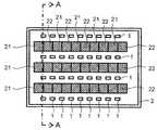
도 4A 내지 4C는 방사선-방출 장치(400)의 예시적인 실시예를 도시한다. 도 4B 및 4C는 도 4A에 BB 및 CC로 표시된 단면 평면들을 따른 개략적 단면 표현을 도시한다. 도 4B 및 4C에서, 상기 단면 평면 AA는 도 4A에 도시된 방사선-방출 장치(400)를 통해 단면을 특성화한다.4A-4C show an exemplary embodiment of a radiation-emitting
이에 의해, 상기 방사선-방출 장치(400)는 이전의 예시적인 실시예에서의 방사선-방출 장치(300)와 유사하게 설계된다. 그러나, 방사선-방출 장치(300)와 다르게, 상기 방사선-방출 장치(400)는 광 박스로서 설계된 반사기(2)를 포함하며, 여기서 복수의 제1 파장 변환 물질들(21) 및 복수의 제2 파장 변환 물질들(22)이 상기 반사기(2)의 제1 및 제2 서브-영역들에 배열된다. 상기 제1 및 제2 파장 변환 물질들(21, 22)을 갖는 상기 제1 및 제2 서브-영역들은 이에 의해 상기 반사기(2) 상에 서로에 대해 교번하여 이웃하는 평행한 직선들을 따라 도포된다.Thereby, the radiation-emitting
더욱이, 벌집 형상인 상기 반사기(2) 상에 평행한 직선들을 따라, LED들 또는 레이저 다이오드들로서 설계된 각각의 복수의 방사선-방출 컴포넌트들(1)이 배열된다. 대안적으로 또는 추가로, 방사선-방출 컴포넌트들(1)은 또한 전반 부분에 설명된 바와 같이 형광 램프들로서 설계될 수 있다.Furthermore, along the parallel straight lines on the
상기 방사선-방출 컴포넌트들(1) 및 상기 제1 및 제2 파장 변환 물질들(21, 22) 위에, 복수의 구멍들(30)을 포함하는 이동가능한 반사 개구(3)가 배열된다. 이에 의해, 도 3A 내지 도 3C에 따른 방사선-방출 장치(300)의 경우에서와 같이 동일한 원리에 따라 상기 방사선-방출 장치(400)에 의해 방출된 2차 방사선이 변경될 수 있도록 상기 구멍들(30)의 각각은 한 쌍의 인접한 제1 및 제2 파장 변환 물질들(21, 22)에 할당된다.Above the radiation-emitting
상기 방출 방향(10)으로 상기 개구(3) 위에, 상기 구멍들(30)을 통해 방출된 상기 전자기 방사선의 빈틈없는 혼합을 허용하며 따라서 상기 2차 방사선의 균일한 방출을 보장하는 확산기(7)가 배열된다. 이에 의해, 상기 확산기(7)는 광의 통과를 허용하지만 투명하지는 않은, 오팔색 판유리의 형태의 반투명한 표면을 갖는 확산기 플레이트로서 설계된다.A
더욱이, 방사선-방출 장치는 또한 복수의 제1 파장 변환 물질(21) 및 방사선-방출 컴포넌트들(1)을 포함하며, 도 1A 내지 도 1C 또는 도 2에 따른 방사선-방출 장치들(100 및 200)의 원리에 따라 상기 2차 방사선의 가변성을 가능하게 할 수 있다.Moreover, the radiation-emitting device also comprises a plurality of first
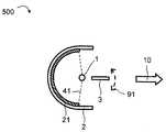
도 5A 및 도 5B는 만곡된 반사기(2)를 포함하는 방사선-방출 장치(500)의 예시적인 실시예를 도시한다. 방사선-방출 컴포넌트(1)와 마주보는 상기 반사기(2)의 오목 표면상에, 상기 1차 방사선을 적어도 부분적으로 전자기 변환 방사선으로 변환할 수 있는 제1 파장 변환 물질(21)이 배열되어 있다. 상기 방사선-방출 컴포넌트(1)는 도시된 예시적인 실시예에서, 상기 도면 평면에서 1차 방사선을 등방성으로 방출할 수 있는 형광 램프를 포함한다. 대안적으로, 상기 방사선-방출 컴포넌트(1)는 또한 방사상 방출 LED 또는 LED 어레이로서 설계될 수 있다. 이전의 예시적인 실시예들에서와 같이, 상기 방사선-방출 장치(500)의 방사선-방출 컴포넌트(1)는 청색 광의 느낌을 갖는 전자기 1차 방사선을 방출하는 한편, 상기 제1 파장 변환 물질(21)은 황색 또는 황적색 광의 느낌을 갖는 변환 방사선을 방출할 수 있다.5A and 5B show an exemplary embodiment of a radiation-emitting
상기 방사선-방출 컴포넌트(1)는 상기 반사기(2)와 개구(3) 사이에 배열된다. 상기 개구(3)는 직접 반사하며, 2중 화살표(90)에 의해 표시된 바와 같이, 상기 도면 평면에서 회전가능하다. 명확성을 위해, 도 5A 및 도 5B는 상기 제1 파장 변환 물질(21) 상에 상기 개구(3) 상의 반사에 의해 또는 직접 조사되는 상기 1차 방사선의 비율(41)만을 도시한다.The radiation-emitting
상기 제1 파장 변환 물질(21) 상에 조사되지 않는 상기 1차 방사선의 비율(41)이 상기 방출 방향(10)(도시되지 않음)으로 직접 방출될 수 있다. 상기 방사선-방출 장치(500)에 의해 방출된 2차 방사선은 상기 1차 방사선의 직접 방출된 부분 및 상기 제1 파장 변환 물질(21)에 의해 방출된 상기 변환 방사선으로 이루어진다. 도 5A 및 도 5B에 도시된 바와 같이, 상기 방사선-방출 컴포넌트(1) 및 상기 반사기(2)에 대해 상기 개구(3)를 회전시킴으로써, 즉 상기 방사선-방출 컴포넌트(1) 및 상기 반사기(2)에 대해 상기 개구(3)의 배향을 변경함으로써, 상기 제1 파장 변환 물질(21) 상에 방출되는 상기 1차 방사선의 비율(41)이 변경될 수 있다. 결과적으로, 상기 방출 방향(10)으로 직접 방출될 수 있는 상기 변환 방사선 및 상기 1차 방사선의 비율은 상기 개구(3)의 상대적인 배향을 변경함으로써 변경될 수 있다.A
따라서, 상기 개구(3)를 회전시킴으로써, 상기 청색 1차 방사선의 비율 및 상기 2차 방사선의 황색 변환 방사선의 비율이 변경될 수 있다. 결과적으로, 상기 2차 방사선의 광 느낌은 도 5B에 따른 개구의 배향에서 더 청색인 광의 느낌과 도 5A에 따른 개구(3)의 배향에서 더 황색이거나 더 황적색인 광의 느낌 사이에서 변화될 수 있다.Thus, by rotating the
상기 직접 반사 개구(3)에 대안적으로, 이는 또한 도 2에서와 같이, 도 5A에서 상기 반사기를 마주보는 표면상에 제3 파장 변환 물질을 가질 수 있다. 상기 개구(3)에 의해 상기 반사기(2)로 되돌아 방출된 제3 파장 변환 물질에 의해 생성된 변환 방사선은, 상기 방출 방향의 상기 반사기(2) 측에서 상기 방출 방향(10)으로 반사될 수 있으며, 따라서 상기 개구의 배향에 따라 상기 2차 방사선 및 그 광 느낌에 기여할 수 있다.Alternatively to the direct
대안적으로 또는 추가로, 회전가능한 개구(3)에, 상기 방사선-방출 장치(500)는 또한 이동가능한 또는 회전가능하고 이동가능한 개구를 포함할 수 있다.Alternatively or additionally, in the
도 1A 내지 도 5B에 관련하여 설명된 상기 1차 방사선 및 상기 변환 방사선에 대한 파장 범위들의 조합들은 순전히 예시적이다. 추가로, 가변적인 백색 및/또는 다색의 조명 느낌을 허용하는 파장 범위들의 다른 조합들이 또한 가능하다.The combinations of wavelength ranges for the primary radiation and the converted radiation described in connection with FIGS. 1A-5B are purely exemplary. In addition, other combinations of wavelength ranges are also possible that allow for a variable white and / or multicolored illumination feel.
상기 예시적인 실시예들을 참조한 설명은 본 발명을 이들 실시예들로 제한하지 않는다. 대신에, 본 발명은 그 특징 또는 조합이 청구범위 또는 예시적인 실시예들에 실제로 명시적으로 개시되지 않더라도, 특히 상기 청구범위에서의 특징들의 임의의 조합을 포함하는 특징들의 모든 조합 및 모든 신규한 특징을 포함한다.The description with reference to the above exemplary embodiments does not limit the invention to these embodiments. Instead, the present invention is directed to all novel and all novel combinations of features, including any combination of features in particular in the claims, even though the feature or combination is not actually explicitly disclosed in the claims or the illustrative embodiments. Includes features
1방사선-방출 컴포넌트 (1)
2반사기
3개구
41차 방사선
5변환 방사선
62차 방사선
7확산기
10방출 방향
21제1 파장 변환 물질
22제2 파장 변환 물질
30구멍
31제3 파장 변환 물질
41, 42상기 1차 방사선의 비율
90변환
91회전
100방사선-방출 장치
200방사선-방출 장치
300방사선-방출 장치
400방사선-방출 장치
500방사선-방출 장치1 Radiation-emitting components (1)
2 reflector
3 opening
4 Primary radiation
5 conversion radiation
6 secondary radiation
7 diffuser
10 release directions
21st wavelength converting material
22 second wavelength converting material
30 holes
31 Third Wavelength Converting Material
41, 42 Ratio of the primary radiation
90 Convert
91 turns
100 radiation-emitting devices
200 radiation-emitting devices
300 radiation-emitting devices
400 radiation-emitting devices
500 radiation-emitting devices
Claims (14)
Translated fromKorean동작 동안 전자기 1차 방사선(4)을 방출하는 적어도 하나의 방사선-방출 컴포넌트(1);
상기 방사선-방출 컴포넌트(1)의 빔 경로에 배열되고 전자기 변환 방사선(5)으로의 상기 1차 방사선(4)의 적어도 부분적인 변환을 위한 제1 파장 변환 물질(21)을 갖는 반사기(2); 및
상기 방사선-방출 컴포넌트(1) 및 상기 반사기(2)에 대해 배향의 관점에서 가변적인 개구(3)
를 포함하고,
상기 개구(3)의 배향을 변경하는 것에 의해, 상기 제1 파장 변환 물질(2) 상에 상기 방사선-방출 컴포넌트(1)에 의해 방출되는 상기 1차 방사선(4)의 비율(41)을 변경함으로써, 그리고 상기 방출된 변환 방사선(5)을 변경함으로써 상기 2차 방사선(6)이 가변적인,
방사선 방출 장치.A radiation-emitting device for emitting an electromagnetic secondary radiation 6 that is variable in the emission direction 10,
At least one radiation-emitting component 1 emitting electromagnetic primary radiation 4 during operation;
Reflector 2 arranged in the beam path of the radiation-emitting component 1 and having a first wavelength converting material 21 for at least partial conversion of the primary radiation 4 into electromagnetic conversion radiation 5. ; And
Openings 3 that are variable in terms of orientation with respect to the radiation-emitting component 1 and the reflector 2
Including,
By changing the orientation of the opening 3, the ratio 41 of the primary radiation 4 emitted by the radiation-emitting component 1 on the first wavelength converting material 2 is changed. And the secondary radiation 6 is variable by altering the emitted converted radiation 5,
Radiation emitting device.
상기 반사기(2)는 상기 1차 방사선(4)의 전자기 변환 방사선(5)으로의 변환을 위해, 상기 제1 파장 변환 물질(21)을 갖는 제1 서브-영역 및 상기 제1 파장 변환 물질(21)과 상이한 제2 파장 변환 물질(22)을 갖는 제2 서브-영역을 포함하고,
상기 개구(3)의 배향을 변경함으로써, 상기 2차 방사선(6)에서의 상기 변환 방사선(5)의 상기 제1 서브-영역에 의해 방출된 비율과 상기 제2 서브-영역에 의해 방출된 비율이 서로에 대해 가변적인,
방사선-방출 장치.The method of claim 1,
The reflector 2 comprises a first sub-region with the first wavelength converting material 21 and the first wavelength converting material for conversion of the primary radiation 4 to electromagnetic converted radiation 5. A second sub-region having a second wavelength converting material 22 different from 21),
By changing the orientation of the opening 3, the ratio emitted by the first sub-region of the converted radiation 5 in the secondary radiation 6 and the ratio emitted by the second sub-region These are variable relative to each other,
Radiation-emitting device.
상기 반사기(2)는 나란하게 교번적으로 배열된 다수의 제1 및 제2 서브-영역들을 포함하는,
방사선-방출 장치.The method according to claim 1 or 2,
The reflector 2 comprises a plurality of first and second sub-regions arranged alternately side by side,
Radiation-emitting device.
상기 반사기(2)는 상기 1차 방사선(4)에 대해 부분적으로 반사하는,
방사선-방출 장치.The method according to claim 1 or 2,
The reflector 2 partially reflects the primary radiation 4,
Radiation-emitting device.
상기 개구(3)는 적어도 부분적으로 반사하는,
방사선-방출 장치.The method according to claim 1 or 2,
The opening 3 reflects at least partially,
Radiation-emitting device.
상기 개구(3)는 제3 파장 변환 물질(31)을 포함하고, 그리고
상기 개구(3)의 배향을 변경함으로써, 상기 제3 파장 변환 물질(31) 상에 상기 방사선-방출 컴포넌트(1)에 의해 방출되는 상기 1차 방사선(4)의 비율이 가변적인,
방사선-방출 장치.The method according to claim 1 or 2,
The opening 3 comprises a third wavelength converting material 31, and
By changing the orientation of the opening 3, the proportion of the primary radiation 4 emitted by the radiation-emitting component 1 on the third wavelength converting material 31 is variable,
Radiation-emitting device.
상기 개구(3)는 적어도 하나의 구멍(30)을 포함하는,
방사선-방출 장치.The method according to claim 1 or 2,
The opening 3 comprises at least one hole 30,
Radiation-emitting device.
상기 변환 방사선(5)의 적어도 일부분은 상기 방사선-방출 장치에 의해 상기 구멍(30)을 통해 방출되는,
방사선-방출 장치.The method of claim 7, wherein
At least a portion of the converted radiation 5 is emitted through the hole 30 by the radiation-emitting device,
Radiation-emitting device.
상기 개구(3)는 복수의 구멍들(30)을 포함하는,
방사선-방출 장치.The method of claim 7, wherein
The opening 3 comprises a plurality of holes 30,
Radiation-emitting device.
상기 방사선-방출 컴포넌트(1)에 대해 상기 개구(3)의 배향이 변환(90) 및/또는 회전(91)에 의해 가변적인,
방사선-방출 장치.The method according to claim 1 or 2,
The orientation of the opening 3 with respect to the radiation-emitting component 1 is variable by translation 90 and / or rotation 91,
Radiation-emitting device.
외부 관찰자에 의해 보여지는 상기 개구(3)는 상기 반사기(2)의 적어도 일부를 커버하고, 상기 반사기(2)는 상기 개구(3)의 배열을 변경함으로써 가변적인,
방사선-방출 장치.The method according to claim 1 or 2,
The opening 3 seen by an external observer covers at least a part of the reflector 2, the reflector 2 being variable by changing the arrangement of the opening 3,
Radiation-emitting device.
상기 개구(3)는 상기 방사선-방출 컴포넌트(1)와 상기 반사기(2) 사이에 배열되는,
방사선-방출 장치.The method according to claim 1 or 2,
The opening 3 is arranged between the radiation-emitting component 1 and the reflector 2,
Radiation-emitting device.
상기 방사선-방출 컴포넌트(1)는 상기 반사기(2)와 상기 개구(3) 사이에 배열되는,
방사선-방출 장치.The method according to claim 1 or 2,
The radiation-emitting component 1 is arranged between the reflector 2 and the opening 3,
Radiation-emitting device.
상기 방사선-방출 컴포넌트(1)는 방사선-방출 반도체 컴포넌트 및/또는 형광 램프를 포함하는,
방사선-방출 장치.The method according to claim 1 or 2,
The radiation-emitting component 1 comprises a radiation-emitting semiconductor component and / or a fluorescent lamp,
Radiation-emitting device.
Applications Claiming Priority (2)
| Application Number | Priority Date | Filing Date | Title |
|---|---|---|---|
| DE102008031996ADE102008031996A1 (en) | 2008-07-07 | 2008-07-07 | Radiation-emitting device |
| DE102008031996.1 | 2008-07-07 |
Publications (1)
| Publication Number | Publication Date |
|---|---|
| KR20110039327Atrue KR20110039327A (en) | 2011-04-15 |
Family
ID=41203843
Family Applications (1)
| Application Number | Title | Priority Date | Filing Date |
|---|---|---|---|
| KR1020117002810AAbandonedKR20110039327A (en) | 2008-07-07 | 2009-06-15 | Radiation-emitting device |
Country Status (8)
| Country | Link |
|---|---|
| US (1) | US20110176305A1 (en) |
| EP (1) | EP2307797B1 (en) |
| JP (1) | JP5130402B2 (en) |
| KR (1) | KR20110039327A (en) |
| CN (1) | CN102084172B (en) |
| AT (1) | ATE540263T1 (en) |
| DE (1) | DE102008031996A1 (en) |
| WO (1) | WO2010003763A1 (en) |
Families Citing this family (41)
| Publication number | Priority date | Publication date | Assignee | Title |
|---|---|---|---|---|
| CA2730719A1 (en)* | 2008-08-08 | 2010-02-11 | Xicato, Inc. | Color tunable light source |
| JP4991834B2 (en) | 2009-12-17 | 2012-08-01 | シャープ株式会社 | Vehicle headlamp |
| JP5232815B2 (en)* | 2010-02-10 | 2013-07-10 | シャープ株式会社 | Vehicle headlamp |
| US9063402B2 (en)* | 2010-03-26 | 2015-06-23 | Nec Corporation | Illuminating optical system and projector using the same |
| DE102010028949A1 (en)* | 2010-05-12 | 2011-11-17 | Osram Gesellschaft mit beschränkter Haftung | headlight module |
| US8733996B2 (en) | 2010-05-17 | 2014-05-27 | Sharp Kabushiki Kaisha | Light emitting device, illuminating device, and vehicle headlamp |
| JP5112476B2 (en)* | 2010-06-28 | 2013-01-09 | シャープ株式会社 | Luminescent body, light emitting device, lighting device, and vehicle headlamp |
| JP5255018B2 (en)* | 2010-05-17 | 2013-08-07 | シャープ株式会社 | Laser downlight and laser downlight system |
| CN102313166B (en)* | 2010-05-17 | 2015-01-14 | 夏普株式会社 | Luminous body, light emitting device, lighting device, and vehicle headlamp |
| DE102010030639B4 (en) | 2010-06-29 | 2013-05-02 | Osram Gmbh | Lighting device with movable converter element |
| DE102010030938A1 (en)* | 2010-07-05 | 2012-01-05 | Osram Gesellschaft mit beschränkter Haftung | Light box and method for mixing light |
| US9816677B2 (en) | 2010-10-29 | 2017-11-14 | Sharp Kabushiki Kaisha | Light emitting device, vehicle headlamp, illumination device, and laser element |
| DE102010062463A1 (en)* | 2010-12-06 | 2012-06-06 | Osram Ag | Lighting-device i.e. vehicle headlight, has phosphor regions individually illuminatable by respective light sources, and aligned for diffuse radiation of light on downstream optical elements, which exhibit different optical properties |
| CN102636946B (en)* | 2011-02-11 | 2016-07-13 | 中强光电股份有限公司 | Light source module and projection device |
| DE102011014845B4 (en)* | 2011-03-23 | 2023-05-17 | OSRAM Opto Semiconductors Gesellschaft mit beschränkter Haftung | Semiconductor light-emitting device and method of manufacturing a semiconductor light-emitting device |
| US20140254165A1 (en)* | 2011-08-15 | 2014-09-11 | Shaun Lee Cutler | Illumination beam adjustment apparatus and illumination apparatus |
| JP5923733B2 (en)* | 2011-10-31 | 2016-05-25 | パナソニックIpマネジメント株式会社 | Light source device and projection display device |
| US8687147B2 (en) | 2011-11-14 | 2014-04-01 | Planck Co., Ltd. | Color regulating device for illumination and apparatus using the same, and method of regulating color |
| DE102011087112B4 (en) | 2011-11-25 | 2022-02-10 | Coretronic Corporation | Lighting device with phosphor on a mobile support |
| CN102563410B (en)* | 2011-12-04 | 2014-08-06 | 深圳市光峰光电技术有限公司 | Light emitting device, projection device and lighting device |
| KR101664507B1 (en)* | 2011-12-08 | 2016-10-10 | 엘지이노텍 주식회사 | Display device |
| CN102720954B (en)* | 2012-01-14 | 2014-08-27 | 深圳市光峰光电技术有限公司 | Light emitting device and light emitting system |
| FR2986305B1 (en)* | 2012-01-30 | 2014-11-21 | Automotive Lighting Rear Lamps France | DEVICE FOR MAKING HOMOGENEOUS THE APPEARANCE OF A MOTOR VEHICLE SIGNALING FIRE |
| WO2013118037A1 (en)* | 2012-02-10 | 2013-08-15 | Koninklijke Philips N.V. | A lighting assembly, a color conversion element, a lamp and a luminaire |
| DE102012203891A1 (en)* | 2012-03-13 | 2013-09-19 | Osram Gmbh | Radiation source unit |
| CN105003843B (en)* | 2012-03-23 | 2017-12-29 | 深圳市绎立锐光科技开发有限公司 | Light source |
| DE102012206086B4 (en)* | 2012-04-13 | 2019-11-28 | Andreas Hierzer | Adjustment device for a luminaire for generating a variable light distribution and luminaire |
| CN103375702A (en)* | 2012-04-23 | 2013-10-30 | 展晶科技(深圳)有限公司 | LED light-emitting device |
| JP5962904B2 (en)* | 2012-04-26 | 2016-08-03 | パナソニックIpマネジメント株式会社 | Light source device and projection display device including the light source device |
| DE102012210195A1 (en) | 2012-06-18 | 2013-12-19 | Osram Gmbh | Device for providing electromagnetic radiation |
| DE102013207226A1 (en)* | 2013-04-22 | 2014-10-23 | Osram Opto Semiconductors Gmbh | Production of a Layer Element for an Optoelectronic Semiconductor Chip |
| DE102013217410A1 (en)* | 2013-09-02 | 2015-03-19 | Osram Opto Semiconductors Gmbh | Optoelectronic module and method for its production |
| DE102013221723A1 (en) | 2013-10-25 | 2015-04-30 | Zumtobel Lighting Gmbh | Melanopic light |
| DE102014213406A1 (en)* | 2014-07-10 | 2016-01-14 | Osram Opto Semiconductors Gmbh | Semiconductor laser component and camera |
| DE102014217353A1 (en) | 2014-08-29 | 2016-03-03 | Osram Gmbh | Lighting device with at least one phosphor ribbon |
| JP6548152B2 (en)* | 2014-09-11 | 2019-07-24 | パナソニックIpマネジメント株式会社 | Lighting device |
| CN107429899A (en)* | 2015-03-09 | 2017-12-01 | 皇家飞利浦有限公司 | Color dot variable illumination device |
| WO2018154992A1 (en)* | 2017-02-27 | 2018-08-30 | 株式会社ジャパンディスプレイ | Display device |
| DK180189B1 (en) | 2017-04-27 | 2020-07-24 | Chromaviso As | Circadian lamp and method of operating such a lamp |
| CN107327801A (en)* | 2017-08-03 | 2017-11-07 | 京东方科技集团股份有限公司 | The adjusting method of LED illumination light color temperature and the LED illumination lamp of adjustable color |
| DE102018120112A1 (en) | 2018-08-17 | 2020-02-20 | Osram Opto Semiconductors Gmbh | Radiation-emitting component |
Family Cites Families (18)
| Publication number | Priority date | Publication date | Assignee | Title |
|---|---|---|---|---|
| JPS5778703A (en)* | 1980-11-04 | 1982-05-17 | Nakamatsu Yoshiro | Reflecting emitter light |
| JPH0192702U (en)* | 1987-12-11 | 1989-06-19 | ||
| JP2993937B1 (en)* | 1998-06-19 | 1999-12-27 | 岡谷電機産業株式会社 | LCD display |
| KR100702273B1 (en)* | 1998-09-28 | 2007-03-30 | 코닌클리즈케 필립스 일렉트로닉스 엔.브이. | Lighting system |
| EP1126995A4 (en)* | 1998-11-02 | 2003-03-19 | Code 3 Inc | Vehicular warning light having a dichroic element |
| US6259103B1 (en)* | 1998-11-12 | 2001-07-10 | The United States Of America As Represented By The Secretary Of The Air Force | Light beam detector |
| US7196390B1 (en)* | 1999-09-26 | 2007-03-27 | 3Dv Systems Ltd. | Solid state image wavelength converter |
| JP4230632B2 (en)* | 2000-01-05 | 2009-02-25 | インターナショナル・ビジネス・マシーンズ・コーポレーション | Computer with keyboard luminaire and portable computer with keyboard luminaire |
| US6323601B1 (en)* | 2000-09-11 | 2001-11-27 | Nordson Corporation | Reflector for an ultraviolet lamp system |
| CN2646554Y (en)* | 2003-10-13 | 2004-10-06 | 璨圆光电股份有限公司 | Light-emitting device for white light-emitting diode lamps |
| CN100492685C (en)* | 2003-12-05 | 2009-05-27 | 三菱电机株式会社 | Light emitting device and lighting fixture using the same |
| US7144131B2 (en)* | 2004-09-29 | 2006-12-05 | Advanced Optical Technologies, Llc | Optical system using LED coupled with phosphor-doped reflective materials |
| CN2745289Y (en)* | 2004-11-04 | 2005-12-07 | 深圳富泰宏精密工业有限公司 | Light guide panel for handset keys |
| DE102005020085A1 (en)* | 2005-04-29 | 2006-11-09 | Osram Opto Semiconductors Gmbh | Motor vehicle headlight |
| JP4354435B2 (en)* | 2005-07-13 | 2009-10-28 | 三菱電機株式会社 | Light emitting device and lighting device |
| US7293908B2 (en)* | 2005-10-18 | 2007-11-13 | Goldeneye, Inc. | Side emitting illumination systems incorporating light emitting diodes |
| US8167796B2 (en)* | 2006-05-12 | 2012-05-01 | Hoya Corporation | Endoscope light source unit |
| DE102007037875A1 (en)* | 2007-08-10 | 2009-02-12 | Osram Gesellschaft mit beschränkter Haftung | Radiation-emitting device |
- 2008
- 2008-07-07DEDE102008031996Apatent/DE102008031996A1/ennot_activeWithdrawn
- 2009
- 2009-06-15WOPCT/EP2009/057373patent/WO2010003763A1/enactiveApplication Filing
- 2009-06-15JPJP2011517059Apatent/JP5130402B2/ennot_activeExpired - Fee Related
- 2009-06-15CNCN2009801263961Apatent/CN102084172B/ennot_activeExpired - Fee Related
- 2009-06-15ATAT09779752Tpatent/ATE540263T1/enactive
- 2009-06-15KRKR1020117002810Apatent/KR20110039327A/ennot_activeAbandoned
- 2009-06-15EPEP09779752Apatent/EP2307797B1/ennot_activeNot-in-force
- 2009-06-15USUS13/003,012patent/US20110176305A1/ennot_activeAbandoned
Also Published As
| Publication number | Publication date |
|---|---|
| WO2010003763A1 (en) | 2010-01-14 |
| EP2307797A1 (en) | 2011-04-13 |
| EP2307797B1 (en) | 2012-01-04 |
| JP2011527093A (en) | 2011-10-20 |
| JP5130402B2 (en) | 2013-01-30 |
| US20110176305A1 (en) | 2011-07-21 |
| CN102084172A (en) | 2011-06-01 |
| ATE540263T1 (en) | 2012-01-15 |
| CN102084172B (en) | 2013-07-24 |
| DE102008031996A1 (en) | 2010-02-18 |
Similar Documents
| Publication | Publication Date | Title |
|---|---|---|
| KR20110039327A (en) | Radiation-emitting device | |
| US11028979B2 (en) | Lighting source using solid state emitter and phosphor materials | |
| US9541243B2 (en) | Light conversion assembly, a lamp and a luminaire | |
| KR100702273B1 (en) | Lighting system | |
| US9312451B2 (en) | Apparatus, method to enhance color contrast in phosphor-based solid state lights | |
| US8042971B2 (en) | Light emitting device (LED) lighting systems for emitting light in multiple directions and related methods | |
| KR100731454B1 (en) | Light emitting device and illumination instrument using the same | |
| US8764224B2 (en) | Luminaire with distributed LED sources | |
| US9512970B2 (en) | Photoluminescence wavelength conversion components | |
| KR20110092313A (en) | Semiconductor light-emitting device comprising an elongated hollow wavelength conversion tube and assembly method thereof | |
| JP2012507139A (en) | Array layout for color mixing | |
| KR20110129968A (en) | Lighting device with remote luminescent material | |
| KR20090026196A (en) | Effective light emitting LED package and method for effective light emitting | |
| EP2627945B1 (en) | Optical element edge treatment for lighting device | |
| TW201020467A (en) | Colour mixing method for consistent colour quality | |
| US20090002979A1 (en) | Light emitting device (led) lighting systems for emitting light in multiple directions and related methods | |
| WO2020173895A1 (en) | Lighting device | |
| US20160254423A1 (en) | Non-magnified led for high center-beam candle power | |
| US20170082248A1 (en) | Led-based linear lamps and lighting arrangements | |
| KR20210109124A (en) | Lighting Device | |
| Kern | Light-emitting diodes in automotive forward lighting applications: Materials engineering solutions to fundamental challenges | |
| JP2008117760A (en) | Lighting device and lighting system | |
| JP2011233268A (en) | Lighting system | |
| Shchekin et al. | Advancements in LED Technology Enabling High-Luminance LEDs | |
| KR20120045883A (en) | Lighting device |
Legal Events
| Date | Code | Title | Description |
|---|---|---|---|
| PA0105 | International application | Patent event date:20110207 Patent event code:PA01051R01D Comment text:International Patent Application | |
| PG1501 | Laying open of application | ||
| A201 | Request for examination | ||
| PA0201 | Request for examination | Patent event code:PA02012R01D Patent event date:20140613 Comment text:Request for Examination of Application | |
| PE0701 | Decision of registration | Patent event code:PE07011S01D Comment text:Decision to Grant Registration Patent event date:20150831 | |
| PC1904 | Unpaid initial registration fee |