KR20110036649A - fan - Google Patents
fanDownload PDFInfo
- Publication number
- KR20110036649A KR20110036649AKR1020117006901AKR20117006901AKR20110036649AKR 20110036649 AKR20110036649 AKR 20110036649AKR 1020117006901 AKR1020117006901 AKR 1020117006901AKR 20117006901 AKR20117006901 AKR 20117006901AKR 20110036649 AKR20110036649 AKR 20110036649A
- Authority
- KR
- South Korea
- Prior art keywords
- nozzle
- air flow
- fan assembly
- mouth
- fan
- Prior art date
- Legal status (The legal status is an assumption and is not a legal conclusion. Google has not performed a legal analysis and makes no representation as to the accuracy of the status listed.)
- Granted
Links
- 238000000034methodMethods0.000claimsdescription16
- 239000003570airSubstances0.000description127
- 230000000694effectsEffects0.000description20
- 238000001816coolingMethods0.000description15
- 239000012530fluidSubstances0.000description8
- 230000001965increasing effectEffects0.000description4
- 238000009826distributionMethods0.000description3
- 230000006698inductionEffects0.000description3
- OKTJSMMVPCPJKN-UHFFFAOYSA-NCarbonChemical compound[C]OKTJSMMVPCPJKN-UHFFFAOYSA-N0.000description2
- 239000012080ambient airSubstances0.000description2
- 229910052799carbonInorganic materials0.000description2
- 230000006835compressionEffects0.000description2
- 238000007906compressionMethods0.000description2
- 230000001939inductive effectEffects0.000description2
- 241000954177Bangana arizaSpecies0.000description1
- 206010020751HypersensitivityDiseases0.000description1
- 230000007815allergyEffects0.000description1
- 230000003321amplificationEffects0.000description1
- 208000003464asthenopiaDiseases0.000description1
- 238000004140cleaningMethods0.000description1
- 230000007423decreaseEffects0.000description1
- 238000007599dischargingMethods0.000description1
- 238000001704evaporationMethods0.000description1
- 230000008020evaporationEffects0.000description1
- 230000005802health problemEffects0.000description1
- 238000005286illuminationMethods0.000description1
- 230000007774longtermEffects0.000description1
- 238000004519manufacturing processMethods0.000description1
- 238000012986modificationMethods0.000description1
- 230000004048modificationEffects0.000description1
- 238000003199nucleic acid amplification methodMethods0.000description1
- 230000003068static effectEffects0.000description1
- 230000000007visual effectEffects0.000description1
Images


Classifications
- F—MECHANICAL ENGINEERING; LIGHTING; HEATING; WEAPONS; BLASTING
- F04—POSITIVE - DISPLACEMENT MACHINES FOR LIQUIDS; PUMPS FOR LIQUIDS OR ELASTIC FLUIDS
- F04D—NON-POSITIVE-DISPLACEMENT PUMPS
- F04D29/00—Details, component parts, or accessories
- F04D29/40—Casings; Connections of working fluid
- F04D29/42—Casings; Connections of working fluid for radial or helico-centrifugal pumps
- F04D29/44—Fluid-guiding means, e.g. diffusers
- F—MECHANICAL ENGINEERING; LIGHTING; HEATING; WEAPONS; BLASTING
- F04—POSITIVE - DISPLACEMENT MACHINES FOR LIQUIDS; PUMPS FOR LIQUIDS OR ELASTIC FLUIDS
- F04D—NON-POSITIVE-DISPLACEMENT PUMPS
- F04D25/00—Pumping installations or systems
- F04D25/02—Units comprising pumps and their driving means
- F04D25/08—Units comprising pumps and their driving means the working fluid being air, e.g. for ventilation
- F—MECHANICAL ENGINEERING; LIGHTING; HEATING; WEAPONS; BLASTING
- F04—POSITIVE - DISPLACEMENT MACHINES FOR LIQUIDS; PUMPS FOR LIQUIDS OR ELASTIC FLUIDS
- F04D—NON-POSITIVE-DISPLACEMENT PUMPS
- F04D29/00—Details, component parts, or accessories
- F04D29/40—Casings; Connections of working fluid
- F—MECHANICAL ENGINEERING; LIGHTING; HEATING; WEAPONS; BLASTING
- F04—POSITIVE - DISPLACEMENT MACHINES FOR LIQUIDS; PUMPS FOR LIQUIDS OR ELASTIC FLUIDS
- F04D—NON-POSITIVE-DISPLACEMENT PUMPS
- F04D29/00—Details, component parts, or accessories
- F04D29/40—Casings; Connections of working fluid
- F04D29/42—Casings; Connections of working fluid for radial or helico-centrifugal pumps
- F04D29/44—Fluid-guiding means, e.g. diffusers
- F04D29/441—Fluid-guiding means, e.g. diffusers especially adapted for elastic fluid pumps
- F—MECHANICAL ENGINEERING; LIGHTING; HEATING; WEAPONS; BLASTING
- F04—POSITIVE - DISPLACEMENT MACHINES FOR LIQUIDS; PUMPS FOR LIQUIDS OR ELASTIC FLUIDS
- F04D—NON-POSITIVE-DISPLACEMENT PUMPS
- F04D29/00—Details, component parts, or accessories
- F04D29/40—Casings; Connections of working fluid
- F04D29/52—Casings; Connections of working fluid for axial pumps
- F04D29/54—Fluid-guiding means, e.g. diffusers
- F04D29/541—Specially adapted for elastic fluid pumps
- F04D29/545—Ducts
- F—MECHANICAL ENGINEERING; LIGHTING; HEATING; WEAPONS; BLASTING
- F04—POSITIVE - DISPLACEMENT MACHINES FOR LIQUIDS; PUMPS FOR LIQUIDS OR ELASTIC FLUIDS
- F04D—NON-POSITIVE-DISPLACEMENT PUMPS
- F04D33/00—Non-positive-displacement pumps with other than pure rotation, e.g. of oscillating type
- F—MECHANICAL ENGINEERING; LIGHTING; HEATING; WEAPONS; BLASTING
- F04—POSITIVE - DISPLACEMENT MACHINES FOR LIQUIDS; PUMPS FOR LIQUIDS OR ELASTIC FLUIDS
- F04F—PUMPING OF FLUID BY DIRECT CONTACT OF ANOTHER FLUID OR BY USING INERTIA OF FLUID TO BE PUMPED; SIPHONS
- F04F5/00—Jet pumps, i.e. devices in which flow is induced by pressure drop caused by velocity of another fluid flow
- F04F5/14—Jet pumps, i.e. devices in which flow is induced by pressure drop caused by velocity of another fluid flow the inducing fluid being elastic fluid
- F04F5/16—Jet pumps, i.e. devices in which flow is induced by pressure drop caused by velocity of another fluid flow the inducing fluid being elastic fluid displacing elastic fluids
- F04F5/20—Jet pumps, i.e. devices in which flow is induced by pressure drop caused by velocity of another fluid flow the inducing fluid being elastic fluid displacing elastic fluids for evacuating
Landscapes
- Engineering & Computer Science (AREA)
- Mechanical Engineering (AREA)
- General Engineering & Computer Science (AREA)
- Physics & Mathematics (AREA)
- Fluid Mechanics (AREA)
- Structures Of Non-Positive Displacement Pumps (AREA)
- Jet Pumps And Other Pumps (AREA)
Abstract
Translated fromKoreanDescription
Translated fromKorean본 발명은 선풍기 조립체에 관한 것이다. 그 바람직한 실시예로서, 본 발명은, 탁상용 선풍기와 같이, 방, 사무실 등의 가내 환경 내의 공기 순환 및 공기 유동을 발생시키기 위한 가정용 선풍기에 관한 것이다.The present invention relates to a fan assembly. As a preferred embodiment, the present invention relates to a domestic fan for generating air circulation and air flow in a home environment, such as a room or an office, such as a table fan.
종래의 가정용 선풍기는 통상적으로 축을 중심으로 회전하도록 설치된 한 쌍의 날 또는 날개, 및 공기 유동을 발생시키도록 한 쌍의 날을 회전시키기 위한 구동 장치를 포함한다. 공기 유동의 이동 및 순환은 '풍속 냉각(wind chill)' 또는 미풍(breeze)을 발생시키므로, 열이 대류 및 증발 작용을 통해 방산될 때, 사용자는 냉각 효과를 경험하게 된다. 그러한 선풍기는 다양한 크기 및 모양이 가능하다. 예를 들면, 천장 선풍기(ceiling fan)는 직경이 1m 이상이고, 공기를 하향 유동시켜 냉방시킬 수 있도록 통상 천장에 매달아 설치된다. 그 반면, 탁상용 선풍기(desk fan)는 직경이 대체로 약 30㎝이고, 통상 자립식(free standing)이고 휴대가 가능하다.Conventional domestic fans typically comprise a pair of blades or vanes installed to rotate about an axis, and a drive device for rotating the pair of blades to generate air flow. The movement and circulation of the air flow creates a 'wind chill' or breeze, so the user experiences a cooling effect when heat is dissipated through convection and evaporation. Such fans are available in a variety of sizes and shapes. For example, a ceiling fan has a diameter of 1 m or more and is usually suspended from the ceiling so as to cool air by flowing downward. Desktop fans, on the other hand, are generally about 30 cm in diameter, are usually free standing and portable.
이러한 유형의 장치의 단점은 사용자가 선풍기의 회전날에 의해 발생된 기류의 전방 유동을 균일하게 느끼지 못한다는 것이다. 이는 날 표면 또는 선풍기의 외향 표면 전반에 걸친 변형 때문이다. 불균일 또는 '초피(choppy)' 공기 유동은 일련의 파동이 있는 바람 또는 강한 바람으로 느껴질 수 있으며, 소음을 낼 수 있다. 또 다른 단점은 선풍기에 의해 발생되는 냉각 효과가 사용자로부터의 이격거리에 따라 감소되지만, 사용자가 가장 큰 냉각 효과를 느낄 수 있는 위치나 거리에 자리하지 않을 수도 있다는 것이다. 이것이 의미하는 바는, 선풍기는 사용자가 선풍기의 이점을 받기 위해 사용자에 아주 근접하게 위치되어야 한다는 것이다.A disadvantage of this type of device is that the user does not feel uniformly the forward flow of airflow generated by the rotary blades of the fan. This is due to the deformation over the blade surface or the outward surface of the fan. Uneven or 'choppy' air flow can be felt as a series of wave winds or strong winds, and can make noise. Another disadvantage is that the cooling effect generated by the fan is reduced according to the distance from the user, but may not be located at a position or distance where the user can feel the greatest cooling effect. This means that the fan must be located very close to the user in order to take advantage of the fan.
다른 유형의 선풍기가 US 2,488,467, US 2,433,795 및 JP 56-167897에 기술되어 있다. US 2,433,795의 선풍기는 선풍기 날개 대신에 회전 측판의 나선형 슬롯을 포함한다. US 2,488,467에 개시된 서큘레이터 선풍기(circulator fan)는 일련의 노즐로부터 공기 유동을 방출시키며, 공기 유동을 발생시키기 위해 모터 및 송풍기나 선풍기를 포함한 대형 베이스부를 포함한다.Other types of fans are described in US 2,488,467, US 2,433,795 and JP 56-167897. The fan of US 2,433,795 includes a helical slot on a rotating side plate instead of a fan blade. The circulator fan disclosed in US Pat. No. 2,488,467 releases air flow from a series of nozzles and includes a large base portion including a motor and a blower or fan to generate air flow.
가정 환경에서는, 가정용 기구가 공간 제약으로 인해 가능한 한 작고 아담한 것이 바람직하다. 예를 들면, 책상 위나 옆에 위치된 선풍기의 베이스부는 서류, 컴퓨터 또는 기타 다른 사무 용품을 위한 영역을 감소시킨다. 종종 전원 연결의 편의성을 위해, 다수의 기구를 전원에 가깝고 또 다른 기구에도 아주 근접한 같은 영역에 위치시켜야 한다.In a home environment, it is desirable for household appliances to be as small and compact as possible due to space constraints. For example, the base of a fan located on or next to a desk reduces the area for documents, computers or other office supplies. Often, for ease of power connection, multiple instruments should be placed in the same area, close to the power source and very close to another instrument.
책상에 배치된 선풍기의 형상 및 구조는 사용자가 이용할 수 있는 작업 영역을 감소시킬 뿐만 아니라, 자연광(또는 인공 광원으로부터의 빛)이 책상 영역에 이르지 못하도록 차단할 수 있다. 환하게 밝은 책상 영역이 정밀 작업 및 독서에 바람직하다. 또한, 환하게 밝은 영역이 눈의 피로 및 저조도에서 장기간 작업함으로 인해 발생될 수 있는 관련 건강 문제를 감소시킬 수 있다.The shape and structure of the fan arranged on the desk not only reduces the working area available to the user, but can also block natural light (or light from an artificial light source) from reaching the desk area. A brightly lit desk area is desirable for precision work and reading. In addition, brightly lit areas can reduce related health problems that can arise from eye fatigue and long-term work at low light levels.
또한, 일부 가정용 기기는 안전상 이유와 세척의 곤란성의 이유로 바깥방향으로 돌출되는 것이 바람직하다.It is also desirable that some household appliances protrude outwards for safety reasons and difficult cleaning.
본 발명의 목적은 종래 기술의 문제점을 제거한 개량된 선풍기 조립체를 제공하는데 있다.It is an object of the present invention to provide an improved fan assembly which eliminates the problems of the prior art.
일 태양에 있어서, 본 발명은 기류를 발생시키기 위한 블레이드가 없는 무블레이드 선풍기 조립체(bladeless fan assembly)를 제공하는 것으로, 무블레이드 선풍기 조립체는 공기 유동을 발생시키기 위한 수단, 공기 유동을 수용하기 위한 내부 통로를 포함한 노즐 및 공기 유동을 방출하기 위한 마우스부(mouth)를 포함하며, 노즐은 선풍기 조립체의 외부에서 공기가 마우스부에서 방출된 공기 유동에 의해 유입되는 개구를 형성하기 위해 축 주위에 연장되고, 공기 유동을 유도하도록 마우스부가 배치된 표면을 포함하며, 표면은 상기 축으로부터 테이퍼가 진 디퓨저부(diffuser portion) 및 디퓨저부의 하류부에 각을 이루며 위치된 가이드부(guide portion)를 포함한다.In one aspect, the present invention provides a bladeless bladeless fan assembly for generating airflow, the bladeless fan assembly comprising: means for generating air flow, an interior for receiving air flow; A nozzle including a passageway and a mouth for discharging air flow, the nozzle extending around the shaft to form an opening outside of the fan assembly by which air flows from the mouth is introduced; And a surface on which the mouth portion is arranged to induce air flow, the surface comprising a diffuser portion tapered from the axis and a guide portion positioned at an angle downstream of the diffuser portion.
바람직하게는, 본 장치에 의해 기존의 블레이드 없이도 기류가 발생되어 냉각 효과가 발생된다. 무블레이드 장치는 공기를 통해 움직이는 선풍기 날개의 소리가 없고, 가동부가 적기 때문에 소음 발생이 적다. 테이퍼가 진 디퓨저부는 선풍기 조립체의 증폭 특성을 강화하는 동시에, 표면에 대한 소음 및 마찰 손실을 최소로 한다. 가이드부의 배열 및 각도에 의해, 개구를 빠져나가는 발산 공기 유동이 형성되거나 프로파일링된다. 바람직하게, 평균 속도는 공기 유동이 가이드부를 지날 때 증가하는데, 이는 사용자가 느끼는 냉각 효과를 증가시킨다. 바람직하게, 가이드부와 디퓨저부의 배열은 사용자의 위치 쪽으로 공기 유동을 유도하는 동시에, 사용자가 '초피(choppy)'유동을 느끼지 않으면서 매끄럽고 균일한 출력을 유지한다. 본 발명은 종래의 선풍기에 의해 발생된 공기 유동과 비교할 때 공기 유동이 유도되고 집중되는 적합한 냉각 효과를 전달하는 선풍기 조립체를 제공한다.
Preferably, the airflow is generated without the existing blades by the present device to produce a cooling effect. The bladeless device has no noise of the fan blades moving through the air and generates little noise since the moving parts are small. The tapered diffuser portion enhances the amplification characteristics of the fan assembly while minimizing noise and frictional losses on the surface. By the arrangement and angle of the guide portion, a diverging air flow exiting the opening is formed or profiled. Preferably, the average speed increases as the air flow passes through the guide, which increases the cooling effect the user feels. Preferably, the arrangement of the guide portion and the diffuser portion induces air flow towards the user's position while maintaining a smooth and uniform output without the user feeling 'choppy' flow. The present invention provides a fan assembly that delivers a suitable cooling effect in which the air flow is induced and concentrated as compared to the air flow generated by conventional fans.
*선풍기 조립체, 및 특히 바람직한 실시예의 선풍기의 다음 설명에서, '무블레이드(bladeless)'라는 용어는 공기 유동이 가동 날개를 사용하지 않고도 선풍기 조립체로부터 전방으로 방출 또는 배출되는 선풍기 조립체를 설명하는데 사용된다. 이 정의에 의하면, 무블레이드 선풍기 조립체는 사용자 쪽으로 또는 방 안으로 공기 유동을 유도하는 가동 날개가 없는 출력 영역 또는 방출 영역을 포함하는 것으로 고려될 수 있다. 무블레이드 선풍기 조립체의 출력 영역에는 펌프, 발전기, 모터 또는 다른 유체 이송 장치, 즉 모터 로터(motor rotor)와 같은 회전 장치 및/또는 공기 유동을 발생시키기 위한 블레이드형 임펠러와 같이 많은 여러가지 공급원 중 하나에 의해 발생되는 1차 공기 유동이 공급될 수 있다. 발생된 1차 공기 유동은 방 공간 또는 선풍기 조립체 외부의 다른 환경으로부터 내부 통로를 거쳐 노즐로 이동한 다음, 다시 노즐의 마우스부를 통해 방 공간으로 배출된다.In the following description of the fan assembly, and the fan of the particularly preferred embodiment, the term 'bladeless' is used to describe the fan assembly in which the air flow is discharged or discharged forward from the fan assembly without the use of movable vanes. . According to this definition, the bladeless fan assembly may be considered to include an output area or discharge area without a movable vane that directs air flow towards or into the user. The output area of the bladeless fan assembly is one of many different sources, such as a pump, generator, motor or other fluid transfer device, ie a rotating device such as a motor rotor and / or a blade-type impeller for generating air flow. The primary air flow generated by this can be supplied. The generated primary air flow moves from the room space or other environment outside the fan assembly through the internal passageway to the nozzle and then back out through the mouth of the nozzle into the room space.
따라서, 무블레이드로서의 선풍기 조립체에 대한 설명은 전원 및 2차 선풍기의 기능에 필요한 모터와 같은 부품의 설명까지 부연하는 것은 아니다. 2차 선풍기의 기능의 예로는 선풍기 조립체의 조명, 조정 및 진동을 들 수 있다.Therefore, the description of the fan assembly as the bladeless does not extend to the description of the components such as the power source and the motor required for the function of the secondary fan. Examples of the function of the secondary fan include illumination, adjustment and vibration of the fan assembly.
디퓨저부와 축 사이에 형성된 각도는 바람직하게 7°내지 20°, 더 바람직하게는 약 15°이다. 이 배열은 효율적인 공기 유동 발생을 가능하게 한다. 바람직한 일 실시예에 따르면, 가이드부는 축을 중심으로 대칭을 이루며 연장된다. 이 배열에 의해, 가이드부는 선풍기 조립체에 의해 발생된 공기 유동이 방출되는 안정되거나 균일한 출력 표면을 형성한다. 바람직하게, 가이드부는 축을 중심으로 실질적으로 원통형을 이루며 연장된다. 이는 선풍기 조립체의 노즐에 의해 형성된 전 개구에 걸쳐 출력된 공기 유동을 안내 및 유도하기 위한 영역을 형성한다. 또한, 원통형 배열은 깔끔하고 균일한 외관의 노즐을 포함한 조립체를 형성한다. 깔끔한 구조가 바람직하며, 사용자나 고객의 마음에 들 것이다.The angle formed between the diffuser portion and the axis is preferably 7 ° to 20 °, more preferably about 15 °. This arrangement allows for efficient air flow generation. According to one preferred embodiment, the guide portion extends symmetrically about the axis. By this arrangement, the guide portion forms a stable or uniform output surface from which the air flow generated by the fan assembly is released. Preferably, the guide portion extends substantially cylindrically about the axis. This forms an area for guiding and directing the air flow output over the entire opening formed by the nozzle of the fan assembly. The cylindrical arrangement also forms an assembly comprising nozzles of a clean and uniform appearance. A neat structure is desirable and will be enjoyed by users or customers.
바람직하게, 노즐은 축 방향으로 50㎜ 이상의 거리만큼 연장된다. 바람직하게, 노즐은 축을 중심으로 300㎜에서 180㎜까지의 거리만큼 연장된다. 이는, 예를 들면 책상에서 작업할 때 사용자의 상체와 얼굴을 시원하게 하는데 적합할 수 있는 것과 같이, 다양한 출력 영역 및 개구 크기의 범위에 걸쳐 공기를 방출하기 위한 대안을 제공한다. 가이드부는 축 방향으로 바람직하게 5㎜ 내지 60㎜, 더 바람직하게는 약 20㎜의 거리만큼 연장된다. 이 거리는 선풍기 조립체로부터 방출된 공기 유동을 유도 및 안내하고, 적절한 냉각 효과를 발생시키기 위한 적합한 가이드 구조를 제공한다. 노즐의 바람직한 크기는 소형의 장치를 구성할 수 있는 동시에, 사용자를 시원하게 하기 위해 선풍기 조립체로부터 적당한 양의 공기 유동을 발생시킨다.Preferably, the nozzle extends by a distance of at least 50 mm in the axial direction. Preferably, the nozzle extends by a distance from 300 mm to 180 mm about the axis. This provides an alternative for releasing air over a range of output areas and opening sizes, such as may be suitable to cool the user's upper body and face when working on a desk, for example. The guide portion preferably extends in the axial direction by a distance of 5 mm to 60 mm, more preferably about 20 mm. This distance provides a suitable guide structure for directing and guiding the air flow discharged from the fan assembly and for generating an appropriate cooling effect. The desired size of the nozzle can constitute a compact device while at the same time generating an appropriate amount of air flow from the fan assembly to cool the user.
노즐은 마우스부에 인접하여 위치된 코안다 표면(Coanda surface)을 포함할 수 있으며, 이 코안다 표면에 걸쳐, 공기 유동을 유도하도록 마우스부가 배치된다. 코안다 표면은 공지된 유형의 표면이며, 이 코안다 표면에 걸쳐, 표면 부근의 출력 오리피스를 빠져나가는 유체 유동이 코안다 효과를 나타낸다. 유체는 표면에 바싹 접근하여, 즉 표면에 거의 밀착하거나 달라 붙어서 표면을 따라 흐르는 경향이 있다. 코안다 효과는 1차 공기 유동을 코안다 표면을 따라 유도하는 이미 입증되고 관련 증거가 많은 유인 방법이다. 코안다 표면의 특징 및 코안다 표면을 따라 흐르는 유체 유동의 효과에 대한 설명은 Scientific America, 214호, 1963년 6월 발행, 84-92쪽의 레바(Reba)가 기고한 기사에서 볼 수 있다. 코안다 표면의 사용을 통해, 선풍기 조립체의 외부로부터 많은 양의 공기가 마우스부로부터 방출된 공기에 의해 개구를 통해 유입된다.The nozzle may comprise a Coanda surface positioned adjacent the mouth portion, over which the mouth portion is positioned to induce air flow. The coanda surface is a surface of a known type, and the fluid flow exiting the output orifice near the surface exhibits a coanda effect over this coanda surface. Fluid tends to flow closely along the surface, ie close to or adhere to the surface. The coanda effect is an already proven and relevant evidence attracting method of inducing primary air flow along the coanda surface. A description of the features of the Coanda surface and the effect of fluid flow along the Coanda surface can be found in an article by Reba, Scientific America, 214, published in June 1963, 84-92. Through the use of the coanda surface, a large amount of air from the outside of the fan assembly is introduced through the opening by the air released from the mouth portion.
바람직한 실시예에서는, 공기 유동이 선풍기 조립체의 노즐을 통해 발생된다. 다음 설명에서는 이러한 공기 유동을 1차 공기 유동이라고 부를 것이다. 1차 공기 유동은 노즐의 마우스부로부터 방출되어, 바람직하게 코안다 표면을 따라 흐른다. 1차 공기 유동은 노즐의 마우스부의 주변 공기를 유인하는데, 이는, 1차 공기 유동과 유인된 공기를 사용자에게 공급하기 위해, 공기 증폭기로서 역할을 한다. 여기서, 유인된 공기를 2차 공기 유동이라고 부를 것이다. 2차 공기 유동은 방 공간, 노즐의 마우스부 주변의 영역 또는 외부 환경 및, 바꾸어 말해, 선풍기 조립체 주위의 다른 영역으로부터 유입되며, 주로 노즐에 의해 형성된 개구를 통해 흐른다. 유인된 2차 공기 유동과 합쳐지는 코안다 표면을 따라 유도된 1차 공기 유동은 노즐에 의해 형성된 개구로부터 전방으로 방출 또는 배출되는 총 공기 유동과 동일하다. 총 공기 유동은 선풍기 조립체가 냉각에 적당한 기류를 발생시키기에 충분하다. 노즐의 마우스부의 주변 공기의 유인은 매끄러운 전체 출력이 유지되면서 1차 공기 유동이 바람직하게 5배 이상, 더 바람직하게는 10배 이상으로 증폭되게 한다.In a preferred embodiment, air flow is generated through the nozzle of the fan assembly. In the following description this air flow will be referred to as the primary air flow. Primary air flow exits the mouth of the nozzle and preferably flows along the Coanda surface. The primary air flow attracts ambient air at the mouth of the nozzle, which serves as an air amplifier to supply the primary air flow and attracted air to the user. Here, the drawn air will be called secondary air flow. Secondary air flow enters from the room space, the area around the mouth of the nozzle or the external environment, in other words, the other area around the fan assembly, and flows primarily through the openings formed by the nozzle. The primary air flow along the Coanda surface combined with the attracted secondary air flow is equal to the total air flow released or expelled forward from the opening formed by the nozzle. The total air flow is sufficient for the fan assembly to generate an airflow suitable for cooling. The attraction of the ambient air to the mouth of the nozzle causes the primary air flow to be amplified preferably at least 5 times, more preferably at least 10 times while maintaining a smooth overall output.
노즐에 의해 형성된 개구로부터 방출되는 기류는 노즐의 직경 전반에 걸쳐 대체로 일정한 속도 분포를 가질 것이다. 전반적으로 유량 및 유동 프로파일은 일부 영역이 층류 또는 부분 층류를 나타내는 플러그 유동(plug flow)으로 설명될 수 있다. 선풍기 조립체에 의해 사용자에게 전달되는 기류는 종래의 다른 장치에 의해 발생된 것보다 더 선형적인 공기 유동 분포를 가지는 저난류 공기 유동이라는 이점을 가질 수 있다. 바람직하게는, 선풍기로부터의 공기 유동은 날 선풍기에 의한 우수한 냉각 효과로서 사용자가 받게 되는 층류 유동을 하면서 개구 및 노즐의 마우스부 주변 영역으로부터 전방으로 배출될 수 있다. 저난류의 층류 공기 유동은 효율적으로 방출 지점에서 빠져나가며, 종래의 선풍기에 의해 발생된 공기 유동보다 에너지 및 난류 속도의 손실이 적다. 사용자에 대한 이점으로, 냉각 효과가 멀리서도 느껴질 수 있으며, 선풍기의 종합 효율이 증가한다는 점이다. 이는 다시 말해, 사용자는 작업 영역이나 책상에서 약간의 거리를 두고 선풍기를 설치해도, 여전히 선풍기의 냉각 효과를 느낄 수 있다는 것이다.The airflow emitted from the opening formed by the nozzle will have a generally constant velocity distribution throughout the diameter of the nozzle. Overall, the flow rate and flow profile can be described as plug flow in which some regions exhibit laminar or partial laminar flow. The airflow delivered to the user by the fan assembly may have the advantage of low turbulent air flow with a more linear air flow distribution than that generated by other conventional devices. Preferably, the air flow from the fan can be discharged forward from the area around the mouth and the mouth of the nozzle with the laminar flow that the user will receive as an excellent cooling effect by the blade fan. The low turbulent laminar air flow exits the discharge point efficiently and has less loss of energy and turbulent flow rate than the air flow generated by conventional fans. For the user, the cooling effect can be felt from a distance and the overall efficiency of the fan increases. In other words, even if the user installs the fan some distance from the work area or desk, the user can still feel the cooling effect of the fan.
바람직하게, 노즐은 루프(loop)를 포함한다. 노즐의 형상은 날 선풍기를 위한 공간을 포함하도록 하는 요건에 한정되지 않는다. 바람직한 일 실시예에 따르면, 노즐은 환형이다. 환형 노즐을 제공함으로써, 선풍기는 잠재적으로 넓은 영역에 이를 수 있다. 또 다른 바람직한 실시예에 따르면, 노즐은 적어도 부분 원형이다. 이 실시예는 선풍기의 다양한 구조적 대안을 제공하여, 사용자나 고객이 할 수 있는 선택의 기회를 증가시킬 수 있다. 또한, 상기 실시예에서, 노즐은 단일 부품으로 제조될 수 있어서, 선풍기 조립체의 복잡성이 줄어들고, 이에 따라 제조 비용이 감소된다. 대안적으로, 노즐은 내부 통로, 마우스부 및 개구를 형성하는 내부 케이싱부와 외부 케이싱부를 포함할 수 있다. 각각의 케이싱부는 다수의 부품 또는 단일의 환형 부품을 포함할 수 있다.Preferably, the nozzle comprises a loop. The shape of the nozzle is not limited to the requirement to include a space for the blade fan. According to one preferred embodiment, the nozzle is annular. By providing an annular nozzle, the fan can potentially reach a large area. According to another preferred embodiment, the nozzle is at least partially circular. This embodiment may provide a variety of structural alternatives to the fan, increasing the chance of choice for the user or customer. In addition, in the above embodiment, the nozzle can be made of a single part, so that the complexity of the fan assembly is reduced, thereby reducing the manufacturing cost. Alternatively, the nozzle may comprise an inner casing portion and an outer casing portion forming an inner passageway, a mouth portion and an opening. Each casing portion may comprise a plurality of parts or a single annular part.
바람직한 실시예에 따르면, 노즐은 내부 통로와 마우스부를 형성하는 1개 이상의 벽을 포함하며, 이 1개 이상의 벽은 마우스부를 형성하는 대향면을 포함한다. 바람직하게는, 상기 1개 이상의 벽은 내벽과 외벽을 포함하고, 마우스부는 내벽과 외벽의 대향면 사이에 형성된다. 바람직하게는, 마우스부는 방출구를 포함하며, 마우스부의 방출구에서의 대향면 사이의 간격은 바람직하게 0.5㎜ 내지 5㎜이다. 본 실시예에 의해, 노즐에는, 표면을 따라 1차 공기 유동을 안내하고, 사용자에게 이르는 비교적 균일한, 또는 거의 균일한 총 공기 유동을 제공할 수 있는, 바람직한 유동 특성이 제공될 수 있다.According to a preferred embodiment, the nozzle comprises at least one wall which forms an interior passageway and a mouth part, the at least one wall comprising opposing surfaces which form a mouth part. Preferably, the at least one wall comprises an inner wall and an outer wall, and the mouth portion is formed between the opposite surface of the inner wall and the outer wall. Preferably, the mouth portion comprises a discharge port and the spacing between the opposing surfaces at the discharge port of the mouth portion is preferably between 0.5 mm and 5 mm. By this embodiment, the nozzle can be provided with desirable flow characteristics that can guide the primary air flow along the surface and provide a relatively uniform or nearly uniform total air flow to the user.
바람직한 선풍기 조립체에서, 노즐을 통해 공기 유동을 발생시키기 위한 수단은 모터 구동식 임펠러를 포함한다. 이는 선풍기 조립체가 효율적인 공기 유동을 발생시키도록 할 수 있다. 공기 유동을 발생시키기 위한 수단은 바람직하게 브러시리스 DC 모터 및 혼합 유동 임펠러를 포함한다. 이는 마찰 손실 및 종래의 브러시 모터에 사용된 브러시로부터의 탄소 부스러기의 발생을 방지할 수 있다. 병원과 같이 깨끗하거나 오염에 민감한 환경에 또는 알레르기가 있는 사람 주변에는 탄소 부스러기 및 배출물을 감소시키는 것이 바람직하다. 날 선풍기에 통상 사용되는 유도 모터가 브러시를 포함하지 않더라도, 브러시리스 DC 모터가 유도 모터보다 훨씬 더 광범위한 작동 속도를 제공할 수 있다.In a preferred fan assembly, the means for generating air flow through the nozzle comprises a motor driven impeller. This may allow the fan assembly to generate an efficient air flow. Means for generating air flow preferably comprise a brushless DC motor and a mixed flow impeller. This can prevent the friction loss and the generation of carbon debris from the brush used in the conventional brush motor. It is desirable to reduce carbon debris and emissions around clean, polluted, sensitive environments such as hospitals or around people with allergies. Although induction motors commonly used in blade fans do not include brushes, brushless DC motors can provide a much wider range of operating speeds than induction motors.
노즐은 선풍기 조립체의 베이스부 또는 다른 부분에 대해 회전 또는 축회전될 수 있다. 이는 노즐이 필요에 따라 사용자를 향하거나 사용자로부터 멀어지게 할 수 있다. 선풍기 조립체는 책상, 마루, 벽 또는 천장 장착식일 수 있다. 이는 사용자에게 냉방을 제공하는 방의 부분을 늘릴 수 있다.The nozzle may be rotated or axially rotated relative to the base or other portion of the fan assembly. This may cause the nozzle to face the user or away from the user as needed. The fan assembly may be desk, floor, wall or ceiling mounted. This may increase the portion of the room that provides cooling to the user.
제2 태양에 따르면, 본 발명은 기류를 발생시키기 위한 무블레이드 선풍기 조립체용 노즐에 관한 것으로, 상기 노즐은 공기 유동을 수용하기 위한 내부 통로 및 공기 유동을 방출하기 위한 마우스부를 포함하며, 상기 노즐은 선풍기 조립체 외부로부터 공기가 마우스부로부터 방출되는 공기에 의해 유입되는 개구를 형성하기 위해 축을 중심으로 연장되고, 상기 노즐은 공기 유동을 유동하도록 마우스부가 배치된 표면을 포함하며, 상기 표면은 상기 축으로부터 테이퍼가 진 디퓨저부 및 디퓨저부의 하류부에 각을 이루며 위치된 가이드부를 포함한다.According to a second aspect, the present invention relates to a nozzle for a bladeless fan assembly for generating airflow, the nozzle comprising an internal passageway for receiving airflow and a mouth portion for releasing the airflow, the nozzle Extends about an axis to form an opening through which air from the outside of the fan assembly is introduced by air discharged from the mouth portion, the nozzle comprising a surface on which the mouth portion is arranged to flow air flow, the surface from the shaft It includes a tapered diffuser portion and a guide portion positioned at an angle downstream of the diffuser portion.
본 발명의 제1 태양과 관련하여 위에서 설명한 특징이 본 발명의 제2 태양에 동일하게 적용될 수 있고, 제2 태양과 관련하여 설명한 특징이 제1 태양에 동일하게 적용될 수도 있다.The features described above in connection with the first aspect of the invention may equally apply to the second aspect of the invention, and the features described in relation to the second aspect may equally apply to the first aspect.
이하에서는, 본 발명의 일 실시예가 첨부 도면을 참조로 하여 설명될 것이다.In the following, an embodiment of the present invention will be described with reference to the accompanying drawings.
도 1은 선풍기 조립체의 정면도이다.
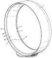
도 2는 도 1의 선풍기 조립체의 일부의 사시도이다.
도 3은 도 1의 선 A-A를 따라 절단된 선풍기 조립체의 일부의 측단면도이다.
도 4는 도 1의 선풍기 조립체의 일부의 확대 측단면 상세도이다.
도 5는 도 3의 방향(F)에서 바라본 도 3의 선 B-B를 따라 절단된 선풍기 조립체의 단면도이다.1 is a front view of the fan assembly.
2 is a perspective view of a portion of the fan assembly of FIG. 1.
3 is a side cross-sectional view of a portion of the fan assembly cut along line AA of FIG. 1.
4 is an enlarged side cross-sectional detail view of a portion of the fan assembly of FIG. 1.
FIG. 5 is a cross sectional view of the fan assembly taken along the line BB of FIG. 3 viewed from the direction F of FIG. 3.
도 1은 선풍기 조립체(100)의 일 예의 정면도를 나타내고 있다. 선풍기 조립체(100)는 중앙 개구(2)를 형성하는 환형 노즐(1)을 포함한다. 또, 도 2 및 도 3을 보면, 노즐(1)은 내부 통로(10), 입구부(mouth)(12) 및 입구부(12)에 인접한 코안다 표면(Coanda surface)(14)을 포함한다. 코안다 표면(14)은, 입구부(12)를 빠져나가 코안다 표면(14)으로 보내지는 1차 공기 유동이 코안다 효과(Coanda effect)에 의해 확장되도록 배치된다. 노즐(1)은 외부 케이싱(18)을 포함한 베이스부(base)(16)에 연결되어 지지된다. 베이스부(16)는 외부 케이싱(18)을 통해 접근가능한 다수의 선택 버튼(20)을 포함하며, 이 선택 버튼을 통해, 선풍기 조립체(100)가 작동될 수 있다. 선풍기 조립체는, 도 1 및 도 3에 도시된 바와 같이, 높이(H), 폭(W), 및 깊이(D)를 갖는다. 노즐(1)은 축(X)에 대해 실질적으로 직교하며 연장하도록 배치된다. 선풍기 조립체의 높이(H)는 축(X)과 직각을 이루며, 노즐(1)로부터 멀리 떨어진 베이스부(16)의 단부에서 베이스부(16)로부터 멀리 떨어진 노즐(1)의 단부까지를 나타낸다. 본 실시예에서의 선풍기 조립체(100)는 높이(H)가 약 530㎜이지만, 선풍기 조립체(100)는 임의의 원하는 높이를 가질 수 있다. 베이스부(16) 및 노즐(1)은 높이(H)와 직각을 이루며 축(X)과도 직각을 이루는 폭(W)을 갖는다. 도 1을 보면, 베이스부(16)의 폭은 부호(W1)로 표시되고, 노즐(1)의 폭은 부호(W2)로 표시되어 있다. 베이스부(16) 및 노즐(1)은 축(X) 방향의 깊이를 갖는다. 도 3을 보면, 베이스부(16)의 깊이는 부호(D1)로 표시되고, 노즐(1)의 깊이는 부호(D2)로 표시되어 있다.1 shows a front view of an example of a
도 3, 도 4 및 도 5는 선풍기 조립체(100)의 더 구체적인 상세도를 나타내고 있다. 노즐(1)을 통해 공기 유동을 발생시키기 위한 모터가 베이스부(16) 내부에 위치된다. 베이스부(16)는 실질적으로 원통형이며, 본 실시예에서의 베이스부(16)는 직경(즉, 폭(W1) 및 깊이(D1))이 약 145㎜이다. 베이스부(16)는 외부 케이싱(18)에 형성된 공기 유입구(24a, 24b)를 더 포함한다. 모터 하우징(26)이 베이스부(16) 내부에 위치된다. 모터(22)는 모터 하우징(26)에 의해 지탱되고, 러버 마운트(rubber mount)나 시일 부재(seal member)에 의해 고정 상태로 유지된다.3, 4 and 5 show more detailed views of the
도시된 실시예에서의 모터(22)는 브러시리스 DC 모터(DC brushless motor)이다. 임펠러(impeller)(30)가 모터(22)로부터 바깥방향으로 연장되는 회전 샤프트에 연결되고, 디퓨저(diffuser)(32)가 임펠러(30)의 하류부에 위치된다. 디퓨저(32)는 나선형 날을 구비한 고정식 고정 디스크(fixed, stationary disc)를 포함한다.The
임펠러(30)의 흡입구(34)가 베이스부(16)의 외부 케이싱(18)에 형성된 공기 유입구(24a, 24b)와 통해 있다. 디퓨저(32)의 방출구(36) 및 임펠러(30)의 배출부는 임펠러(30)에서 노즐(1)의 내부 통로(10)로의 공기 유동을 형성하기 위해 베이스부(16) 내부에 위치된 중공형 통로부 또는 덕트와 통해 있다. 모터(22)는 전기 연결부 및 전원 장치에 연결되며, 제어기(도시되지 않음)에 의해 제어된다. 제어기와 다수의 선택 버튼(20) 사이의 연결이 사용자로 하여금 선풍기 조립체(100)를 조작할 수 있도록 한다.
이제, 도 3 및 도 4를 참조로 하여 노즐(1)의 특징을 설명할 것이다. 노즐(1)의 모양은 환상형이다. 본 실시예에서의 노즐(1)은 직경이 약 350㎜이지만, 노즐은 임의의 원하는 직경, 예를 들면 300㎜의 직경을 가질 수 있다. 내부 통로(10)는 환상형이고, 노즐(1) 내에 연속 루프(continuous loop) 또는 덕트로 형성된다. 노즐(1)은 내부 통로(10)와 입구부(12)를 이루는 1개 이상의 벽에 의해 형성된다. 본 실시예에서의 노즐(1)은 내벽(38) 및 외벽(40)을 포함한다. 도시된 실시예에서, 내벽(38) 및 외벽(40)은 내벽(38)과 외벽(40)이 서로 가까워지도록 고리 또는 접힌 모양으로 배치된다. 내벽(38)과 외벽(40)의 대향면은 함께 마우스부(12)를 형성한다. 마우스부(12)는 X축을 중심으로 하여 연장된다. 마우스부(12)는 폭이 방출구(44)로 좁혀지는 테이퍼부(tapered region)(42)를 포함한다. 방출구(44)는 노즐(1)의 내벽(38)과 노즐(1)의 외벽(40) 사이에 형성된 갭(gap) 또는 간격을 포함한다. 마우스부(12)의 방출구(44)에서 내벽(38)과 외벽(40)의 대향면 사이의 간격은 0.5㎜ 내지 5㎜의 범위에 있도록 선택된다. 간격의 선택은 선풍기의 바람직한 성능 특성에 따라 결정될 것이다. 본 실시예에서, 방출구(44)는 폭이 약 1.3㎜이며, 마우스부(12) 및 방출구(44)는 중심이 내부 통로(10)와 동일하다.The features of the
마우스부(12)는 표면, 즉 코안다 표면(14)에 인접한다. 도시된 실시예의 노즐(1)의 표면은 코안다 표면(14)의 하류부에 위치된 디퓨저부(46) 및 디퓨저부(46)의 하류부에 위치된 가이드부(48)를 더 포함한다. 디퓨저부(46)는 선풍기 조립체(100)로부터 전달 또는 배출된 기류의 유동을 보조하도록 하기 위해 축(X)으로부터 테이퍼가 지도록 배치된 디퓨저 표면(50)을 포함한다. 도 3에 도시된 예에서, 노즐(1)의 마우스부(12) 및 전체 배열은 디퓨저 표면(50)과 축(X) 사이에 형성된 각도가 약 15°를 이루는 식으로 되어 있다. 각도는 공기가 코안다 표면(14) 및 디퓨저부(46)에 걸쳐 효율적으로 유동할 수 있도록 선택된다. 가이드부(48)는 사용자로의 냉각 공기 유동의 효율적인 전달을 더욱 촉진하기 위하여 디퓨저 표면(50)에 소정의 각도를 이루며 배치된 가이드면(52)을 포함한다. 도시된 실시예에서, 가이드면(52)은 축(X)에 실질적으로 평행하게 배치되고, 실질적으로 원통형을 이루며, 마우스부(12)로부터 방출되는 공기 유동에 실질적으로 균일한 면을 이루고 있다.The
도시된 실시예의 노즐(1)의 표면은 가이드부(48)의 하류부에 위치되고 마우스부(12)로부터 멀리 떨어져 있는 바깥방향 돌출면(outwardly flared surface)(54)에서 종결된다. 돌출면(54)은 선풍기 조립체(1)로부터 공기 유동이 방출 및 배출되는 원형 개구(2)를 형성하는 테이퍼링부(tapering portion)(56)와 팁부(tip)(58)를 포함한다. 테이퍼링부(56)는 테이퍼링부(56)와 축 사이에 형성된 각도가 약 45°를 이루는 식으로 축(X)으로부터 테이퍼가 지도록 형성된다. 테이퍼링부(56)는 축에 소정의 각도를 이루며 배치되며, 이 각도는 디퓨저 표면(50)과 축 사이에 형성된 각도보다 더 크다. 돌출면(54)의 테이퍼링부(56)에 의해, 유선형으로 테이퍼가 진 시각적 효과가 얻어진다. 돌출면(54)의 형상과 조화에 의해, 디퓨저부(46) 및 가이드부(48)를 포함하는 노즐(1)의 비교적 두꺼운 단면이 감소된다. 테이퍼링부(56)가 사용자의 눈을 축(X)으로부터 팁부(58)를 향해 바깥방향 및 멀어지는 방향으로 안내하고 이르게 한다. 이러한 배열에 의해, 외관은 사용자 또는 고객이 대개 선호하는 날카롭고 가벼우며 깔끔한 구조가 된다.The surface of the
노즐(1)은 축 방향으로 약 50㎜ 거리만큼 연장된다. 디퓨저부(46) 등의 노즐(1)의 전체 프로파일은 어느 정도는 익형(aerofoil shape)에 기반을 둔다. 도시된 예에서, 디퓨저부(46)는 노즐(1)의 총 깊이의 약 2/3 거리만큼 연장되고, 가이드부(48)는 노즐의 총 깊이의 약 1/6 거리만큼 연장된다.The
상술한 선풍기 조립체(100)는 다음에 설명하는 방식에 따라 작동된다. 사용자가 선풍기 조립체(100)를 작동 또는 가동시키기 위해 다수의 버튼(20)을 적절히 선택하여 사용하면, 신호 등의 정보가 모터(22)를 구동시키기 위해 보내진다. 그러면, 모터(22)는 가동되어, 공기가 공기 유입구(24a, 24b)를 통해 선풍기 조립체(100) 안으로 유입된다. 바람직한 실시예에서는, 공기가 초당 약 20리터 내지 30리터, 바람직하게는 초당 약 27리터(27l/s)의 양으로 유입된다. 공기는 도 3의 화살표(F')로 표시된 경로를 따라 외부 케이싱(18)을 통해 임펠러(30)의 흡입구(34) 쪽으로 들어간다. 디퓨저(32)의 방출구(36) 및 임펠러(30)의 배출부를 통해 배출되는 공기 유동은 내부 통로(10)를 통해 정반대 방향으로 흐르는 두 공기 유동으로 나뉜다. 공기 유동은 마우스부(12)로 들어갈 때 압축되고, 마우스부(12)의 방출구(44)에서 더욱 압축된다. 압축은 시스템 내에 압력을 발생시킨다. 모터(22)는 400kPa 이상의 압력을 갖는 노즐(16)을 통해 공기 유동을 발생시킨다. 이에 따라 발생된 공기 유동은 압축에 의해 발생된 압력을 압도하여, 1차 공기 유동으로서 방출구(44)를 통해 배출된다.The
1차 공기 유동의 출력 및 방출은 추가의 공기를 선풍기 조립체(100) 안으로 빨아들이는 효과를 나타내는 공기 유입구(24a, 24b)의 저압부를 발생시킨다. 선풍기 조립체(100)의 작동은 높은 공기 유동을 노즐(1)을 통해 유도하고, 개구(2)를 통해 배출시킨다. 1차 공기 유동은 코안다 표면(14), 디퓨저 표면(50) 및 가이드 표면(52)에 걸쳐 이동된다. 1차 공기 유동은 가이드부(48) 및 디퓨저 표면(50)에 대한 가이드 표면(52)의 각도 배열에 의해 사용자 쪽으로 모아지거나 집중된다. 외부 환경, 특히 방출구(44)의 주위 영역 및 노즐(1)의 외부 에지 주위로부터 공기를 유인함으로써, 2차 공기 유동이 발생된다. 1차 공기 유동에 의해 유인된 2차 공기 유동의 일부 또한 디퓨저 표면(48)에 걸쳐 안내될 수도 있다. 이 2차 공기 유동은 개구(2)를 통과하고, 1차 공기 유동과 결합하여, 노즐(1)로부터 전방으로 방출되는 총 공기 유동을 형성한다.The output and discharge of the primary air flow creates a low pressure portion of the
유인과 확장의 결합에 의해, 선풍기 조립체(100)의 개구(2)로부터 총 공기 유동이 발생되며, 이 총 공기 유동은 배출 영역에 인접한 그러한 코안다 또는 확장 표면을 포함하지 않은 선풍기 조립체로부터 출력된 공기의 유동보다 더 크다.By the combination of attraction and expansion, a total air flow is generated from the
다음으로는, 디퓨저부(46)에 걸친 공기 유동의 분포 및 이동에 대해, 표면의 유체 역학적 관점에서 설명될 것이다.Next, the distribution and movement of the air flow over the
일반적으로, 디퓨저는 공기와 같은 유체의 평균 속도를 낮추는 기능을 한다. 이는 제어 확장된 면적 또는 부피를 통해 공기를 이동시킴으로써 달성된다. 유체가 이동하는 공간을 형성하는 확장 유로 또는 구조는 유체가 겪는 팽창 또는 확장을 서서히 발생시킬 수 있어야 한다. 거칠거나 급격한 확장은 공기 유동을 중단시켜, 팽창 영역에서 와류를 형성시킬 것이다. 이 경우, 공기 유동은 확장 표면으로부터 분리될 수 있어서, 불균일한 유동이 발생될 것이다. 와류는 바람직하지 못한 공기 유동, 특히 선풍기와 같은 가정용 제품에서 난류를 증가시켜 관련 소음을 발생시킨다.In general, the diffuser serves to lower the average velocity of a fluid such as air. This is accomplished by moving the air through a controlled expanded area or volume. Expansion passages or structures that form a space in which the fluid moves must be able to slowly produce the expansion or expansion that the fluid experiences. Rough or abrupt expansion will disrupt the air flow, forming a vortex in the expansion zone. In this case, the air flow can be separated from the expanding surface, resulting in non-uniform flow. Vortex increases the turbulence in undesired air flows, especially household products such as fans, resulting in associated noise.
점진적 확장을 얻고, 공기의 속도를 고속에서 저속으로 서서히 바꾸기 위해, 디퓨저는 기하학적으로 방사형일 수 있다. 위에서 설명한 배열에 따르면, 디퓨저부(46)의 구조에 의해 선풍기 조립체 내에 난류 및 와류의 발생이 방지된다.In order to obtain a gradual expansion and to slowly change the speed of the air from high speed to low speed, the diffuser can be geometrically radial. According to the arrangement described above, the structure of the
디퓨저 표면(50)을 지나 디퓨저부(46)를 넘어가는 공기 유동은 디퓨저부(46)에 의해 형성된 통로를 통해 발산했던 것과 같이 계속해서 발산하려 할 수 있다. 가이드부(48)가 공기 유동에 미치는 영향은 선풍기 개구로부터 배출 또는 출력된 공기 유동이 사용자 쪽으로 또는 방 안으로 모아지거나 집중되도록 하는 것이다. 그 결과, 사용자에서의 냉각 효과가 실질적으로 개선된다.Air flow past the
공기 유동의 확장과, 디퓨저부(46) 및 가이드부(48)에 의해 얻어진 균일한 발산 및 수렴의 결합에 의해, 공기 유동은 그러한 디퓨저부(46) 및 가이드부(48)를 포함하지 않은 선풍기 조립체로부터 출력된 공기 유동보다 균일해지고 덜 난류적이 된다.By the expansion of the air flow and the combination of the uniform divergence and convergence obtained by the
생성된 공기 유동의 확장 및 층류 형태에 의해, 공기의 유동이 노즐(1)로부터 사용자 쪽으로 지속적으로 유도된다. 바람직한 실시예에 따르면, 선풍기 조립체(100)로부터 방출된 공기의 질량 유량은 450l/s 이상, 바람직하게는 600l/s 내지 700l/s이다. 사용자로부터 최대 3 노즐 직경(즉, 약 1000㎜ 내지 1200㎜)의 거리에서의 유량은 약 400l/s 내지 500l/s이다. 총 공기 유동은 약 3m/s 내지 4m/s의 속도를 갖는다. 표면과 축(X) 사이에 형성된 각도를 줄임으로써 속도가 더 높아질 수 있다. 각도가 작아지면, 총 공기 유동은 더욱 응축되어 나가는 방식으로 방출된다. 이러한 유형의 공기 유동은 고속으로 방출되는 경향이 있지만, 질량 유량이 감소된다. 반대로, 표면과 축 사이의 각도를 크게 하면, 질량 유량이 증가될 수 있다. 이러한 경우에, 방출된 공기의 유동 속도는 감소되지만, 발생되는 질량 유량은 증가한다. 이와 같이, 선풍기 조립체의 성능은 표면과 축(X) 사이에 형성된 각도를 바꿈으로써 변경될 수 있다.By the expansion and laminar flow pattern of the generated air flow, the flow of air is continuously directed from the
본 발명은 상기 상세한 설명에 국한되지는 않는다. 당업자에게 있어 변형예는 명백할 것이다. 예를 들면, 선풍기는 높이 또는 직경이 상이하게 구성될 수 있다. 선풍기의 베이스부 및 노즐은 깊이, 폭 및 높이가 상이하게 구성될 수 있다. 선풍기는 반드시 책상에 위치될 필요는 없고, 자립식, 벽 장착식 또는 천장 장착식일 수 있다. 선풍기 형상은 공기의 냉각 유동이 필요한 모든 종류의 장소 또는 위치에 적합하도록 구성될 수 있다. 휴대용 선풍기는 소형 노즐, 즉 직경이 5㎝인 노즐을 포함할 수 있다. 노즐을 통해 공기 유동을 발생시키기 위한 수단은 모터, 또는 선풍기 조립체가 실내에 기류를 발생시킬 수 있도록 사용될 수 있는 모든 송풍기 또는 진공원과 같은 공기 방출 장치일 수 있다. 예로는, AC 유도 모터 또는 브러시리스 DC 모터의 형태와 같은 모터를 들 수 있지만, 공기 유동을 발생 및 생성시키기 위해 제어된 유체 유동을 제공하는 펌프 등의 수단과 같이 모든 적합한 공기 이동 또는 공기 운반 장치를 들 수도 있다. 모터의 특징부로는 디퓨저, 또는 모터 하우징에서 그리고 모터를 통해 손실된 어느 정도의 정압을 회복하기 위해 모터의 하류부에 위치된 보조 디퓨저를 들 수 있다.The invention is not limited to the above description. Modifications will be apparent to those skilled in the art. For example, the fan may be configured to have a different height or diameter. The base portion and the nozzle of the fan may be configured differently in depth, width and height. The fan does not necessarily need to be located at a desk and may be self-supporting, wall mounted or ceiling mounted. The fan shape may be configured to suit all kinds of places or locations where a cooling flow of air is required. The portable fan may include a small nozzle, that is, a nozzle 5 cm in diameter. The means for generating air flow through the nozzle can be a motor or an air releasing device such as any blower or vacuum source that can be used to allow the fan assembly to generate airflow in the room. Examples include motors, such as in the form of AC induction motors or brushless DC motors, but any suitable air movement or air carrier such as a means such as a pump that provides controlled fluid flow to generate and generate air flow. You can also listen. Features of the motor include a diffuser or an auxiliary diffuser located downstream of the motor to recover some static pressure lost in and through the motor housing.
마우스부의 방출구는 변경될 수 있다. 마우스부의 방출구는 공기 유동을 극대화하기 위해 다양한 간격으로 폭이 넓혀지거나 좁혀질 수 있다. 마우스부에 의해 방출된 공기 유동은 코안다 표면과 같은 표면에 걸쳐 지날 수 있고, 대안적으로 공기 유동은 마우스부를 통해 방출되어, 인접한 표면에 걸쳐 지나지 않으면서 선풍기 조립체로부터 전방으로 배출될 수 있다. 코안다 효과는 다수의 다른 표면에 걸쳐 일어날 수 있거나, 다수의 내부 또는 외부 구조가 필요한 유동 및 유인을 얻기 위해 조합되어 사용될 수 있다. 디퓨저부는 다양한 디퓨저 길이 및 구조로 구성될 수 있다. 가이드부는 다양한 길이로 이루어지며, 다양한 선풍기 요건 및 다양한 유형의 선풍기 성능에 있어 필요에 따라 다수의 다른 위치 및 방향에 배치될 수 있다. 공기 유동의 효과를 유도하거나 집중하는 효과는 다수의 다른 방법에 의해 얻어질 수 있는데, 예를 들면 가이드부는 형상을 갖는 표면을 가지거나, 노즐과 축(X)의 중심에서 멀어지거나 중심을 향해 구부러질 수 있다.The discharge port of the mouth portion can be changed. The outlet of the mouth can be widened or narrowed at various intervals to maximize air flow. The air flow released by the mouth can pass over a surface, such as a Coanda surface, and alternatively the air flow can be released through the mouth, exiting forward from the fan assembly without passing over adjacent surfaces. The Coanda effect can occur over a number of different surfaces, or can be used in combination to obtain the flow and attraction that requires a number of internal or external structures. The diffuser portion can be configured in various diffuser lengths and structures. The guides are of various lengths and can be placed in a number of different positions and orientations as needed for various fan requirements and various types of fan performance. The effect of inducing or concentrating the effect of the air flow can be obtained by a number of different methods, for example the guide portion has a shaped surface, or is bent away from or bent towards the center of the nozzle and axis (X). Can lose.
다른 형상의 노즐을 생각해 볼 수 있다. 예를 들면, 타원형, '레이스트랙(racetrack)'형, 단일 스트립 또는 라인, 또는 블록형의 노즐이 사용될 수 있다. 선풍기 조립체는 날이 없을 때 선풍기의 중앙부에 접근할 수 있다. 이것이 의미하는 바는, 조명 장치 또는 시계 또는 LCD 디스플레이와 같은 추가 특징부가 노즐에 의해 형성된 개구 내에 설치될 수 있다는 것이다.Other shaped nozzles can be considered. For example, elliptical, 'racetrack' type, single strip or line, or block type nozzles may be used. The fan assembly can approach the center of the fan when there is no blade. This means that additional features such as lighting devices or watches or LCD displays can be installed in the openings formed by the nozzles.
다른 특징부로는 사용자가 노즐의 위치를 용이하게 이동시키고 조절할 수 있도록 하는 회전식 또는 틸트식(tiltable) 베이스부를 들 수 있다.
Other features include a rotatable or tiltable base that allows the user to easily move and adjust the position of the nozzle.
Claims (15)
Translated fromKorean공기 유동을 유입되기 위한 내부 통로, 및 상기 공기 유동을 방출시키기 위한 마우스부를 포함하고,
상기 노즐은,
상기 마우스부로부터 방출되는 공기 유동에 의해 상기 선풍기 조립체 외부로부터 공기가 유입되는 개구를 형성하기 위해 축을 중심으로 하여 연장되며, 상기 공기 유동을 유도할 수 있도록 상기 마우스부가 배치되는 표면을 포함하고,
상기 표면은 상기 축으로부터 테이퍼가 진 디퓨저부 및 상기 디퓨저부의 하류부에 각을 이루며 위치된 가이드부를 포함하는, 노즐.A nozzle for a bladeless fan assembly for generating airflow,
An inner passage for introducing an air flow, and a mouth portion for releasing the air flow,
The nozzle,
An air flow discharged from the mouth portion and extending about an axis to form an opening through which air is introduced from outside the fan assembly, and including a surface on which the mouth portion is disposed to induce the air flow;
And the surface includes a tapered diffuser portion from the shaft and a guide portion positioned at an angle downstream of the diffuser portion.
상기 디퓨저부와 상기 축 사이에 형성된 각도는 7°내지 20°인, 노즐.The method of claim 1,
And the angle formed between the diffuser portion and the axis is 7 ° to 20 °.
상기 가이드부는 상기 축을 중심으로 하여 원통을 이루며 연장된, 노즐.The method according to claim 1 or 2,
And the guide portion extends in a cylindrical shape about the axis.
상기 축 방향으로 50㎜ 이상의 거리만큼 연장되는, 노즐.The method according to claim 1 or 2,
And a nozzle extending by a distance of 50 mm or more in the axial direction.
상기 축을 중심으로 하여 300㎜ 내지 1800㎜의 거리만큼 연장되는, 노즐.The method according to claim 1 or 2,
And a nozzle extending about 300 mm to 1800 mm about the axis.
상기 가이드부는 상기 축을 중심으로 하여 대칭을 이루며 연장된, 노즐.The method according to claim 1 or 2,
And the guide portion extends symmetrically about the axis.
상기 가이드부는 상기 축 방향으로 5㎜ 내지 60㎜의 거리만큼 연장된, 노즐.The method according to claim 1 or 2,
And the guide portion extends by a distance of 5 mm to 60 mm in the axial direction.
루프의 형태로 되어 있는, 노즐.The method according to claim 1 or 2,
Nozzle in the form of a loop.
환형 노즐의 형태로 되어 있는, 노즐.The method according to claim 1 or 2,
Nozzle in the form of an annular nozzle.
적어도 부분적으로 원형인, 노즐.The method according to claim 1 or 2,
At least partially circular.
상기 내부 통로와 상기 마우스부를 형성하는 1개 이상의 벽을 포함하며, 상기 1개 이상의 벽은 상기 마우스부를 형성하는 대향면을 포함한, 노즐.The method according to claim 1 or 2,
And at least one wall forming said interior passageway and said mouth portion, said at least one wall comprising opposing surfaces defining said mouth portion.
상기 1개 이상의 벽은 내벽 및 외벽을 포함하며, 상기 마우스부는 상기 내벽과 상기 외벽의 대향면 사이에 형성된, 노즐.The method of claim 11,
Wherein said at least one wall comprises an inner wall and an outer wall, wherein said mouth portion is formed between said inner wall and an opposing surface of said outer wall.
상기 마우스부는 방출구를 포함하고, 상기 마우스부의 상기 방출구에서의 상기 대향면 사이의 간격은 0.5㎜ 내지 5㎜인, 노즐.The method of claim 11,
And the mouth portion comprises a discharge port, wherein the spacing between the opposing surfaces at the discharge port of the mouth part is between 0.5 mm and 5 mm.
상기 디퓨저부와 상기 축 사이에 형성된 각도는 15°인, 노즐.The method of claim 1,
And the angle formed between the diffuser portion and the axis is 15 °.
상기 가이드부는 상기 축 방향으로 20㎜의 거리만큼 연장된, 노즐.The method according to claim 1 or 2,
And the guide portion extends by a distance of 20 mm in the axial direction.
Applications Claiming Priority (3)
| Application Number | Priority Date | Filing Date | Title |
|---|---|---|---|
| GB0817362AGB2463698B (en) | 2008-09-23 | 2008-09-23 | A fan |
| GB0817362.7 | 2008-09-23 | ||
| PCT/GB2009/051045WO2010035018A1 (en) | 2008-09-23 | 2009-08-21 | A fan |
Related Parent Applications (1)
| Application Number | Title | Priority Date | Filing Date |
|---|---|---|---|
| KR1020117006149ADivisionKR101038000B1 (en) | 2008-09-23 | 2009-08-21 | fan |
Publications (2)
| Publication Number | Publication Date |
|---|---|
| KR20110036649Atrue KR20110036649A (en) | 2011-04-07 |
| KR101293593B1 KR101293593B1 (en) | 2013-08-13 |
Family
ID=39952017
Family Applications (2)
| Application Number | Title | Priority Date | Filing Date |
|---|---|---|---|
| KR1020117006901AActiveKR101293593B1 (en) | 2008-09-23 | 2009-08-21 | A fan |
| KR1020117006149AActiveKR101038000B1 (en) | 2008-09-23 | 2009-08-21 | fan |
Family Applications After (1)
| Application Number | Title | Priority Date | Filing Date |
|---|---|---|---|
| KR1020117006149AActiveKR101038000B1 (en) | 2008-09-23 | 2009-08-21 | fan |
Country Status (11)
| Country | Link |
|---|---|
| US (2) | US7931449B2 (en) |
| EP (1) | EP2342466B1 (en) |
| JP (2) | JP4756286B2 (en) |
| KR (2) | KR101293593B1 (en) |
| CN (3) | CN201943969U (en) |
| AU (2) | AU2009295640B2 (en) |
| BR (1) | BRPI0914187B8 (en) |
| CA (1) | CA2737373C (en) |
| GB (1) | GB2463698B (en) |
| RU (1) | RU2463483C1 (en) |
| WO (1) | WO2010035018A1 (en) |
Cited By (2)
| Publication number | Priority date | Publication date | Assignee | Title |
|---|---|---|---|---|
| KR20140031400A (en)* | 2011-07-27 | 2014-03-12 | 다이슨 테크놀러지 리미티드 | Fan assembly |
| KR20180002090U (en) | 2016-12-29 | 2018-07-09 | 대우조선해양 주식회사 | Thruster for ship without blade |
Families Citing this family (175)
| Publication number | Priority date | Publication date | Assignee | Title |
|---|---|---|---|---|
| GB0814835D0 (en) | 2007-09-04 | 2008-09-17 | Dyson Technology Ltd | A Fan |
| GB2463698B (en) | 2008-09-23 | 2010-12-01 | Dyson Technology Ltd | A fan |
| GB2464736A (en) | 2008-10-25 | 2010-04-28 | Dyson Technology Ltd | Fan with a filter |
| GB2466058B (en)* | 2008-12-11 | 2010-12-22 | Dyson Technology Ltd | Fan nozzle with spacers |
| GB2468320C (en) | 2009-03-04 | 2011-06-01 | Dyson Technology Ltd | Tilting fan |
| GB2468325A (en)* | 2009-03-04 | 2010-09-08 | Dyson Technology Ltd | Height adjustable fan with nozzle |
| NZ593318A (en) | 2009-03-04 | 2012-11-30 | Dyson Technology Ltd | An annular fan assembly with a silencing member |
| GB2468331B (en) | 2009-03-04 | 2011-02-16 | Dyson Technology Ltd | A fan |
| GB2468317A (en) | 2009-03-04 | 2010-09-08 | Dyson Technology Ltd | Height adjustable and oscillating fan |
| GB2468315A (en) | 2009-03-04 | 2010-09-08 | Dyson Technology Ltd | Tilting fan |
| GB2468326A (en) | 2009-03-04 | 2010-09-08 | Dyson Technology Ltd | Telescopic pedestal fan |
| GB2468323A (en) | 2009-03-04 | 2010-09-08 | Dyson Technology Ltd | Fan assembly |
| CN202056982U (en) | 2009-03-04 | 2011-11-30 | 戴森技术有限公司 | Humidifying device |
| GB2468322B (en) | 2009-03-04 | 2011-03-16 | Dyson Technology Ltd | Tilting fan stand |
| PL2276933T3 (en) | 2009-03-04 | 2011-10-31 | Dyson Technology Ltd | A fan |
| GB2468312A (en) | 2009-03-04 | 2010-09-08 | Dyson Technology Ltd | Fan assembly |
| KR101395177B1 (en) | 2009-03-04 | 2014-05-15 | 다이슨 테크놀러지 리미티드 | A fan |
| GB0903682D0 (en) | 2009-03-04 | 2009-04-15 | Dyson Technology Ltd | A fan |
| GB2468329A (en) | 2009-03-04 | 2010-09-08 | Dyson Technology Ltd | Fan assembly |
| GB0919473D0 (en) | 2009-11-06 | 2009-12-23 | Dyson Technology Ltd | A fan |
| GB2478927B (en) | 2010-03-23 | 2016-09-14 | Dyson Technology Ltd | Portable fan with filter unit |
| GB2478925A (en) | 2010-03-23 | 2011-09-28 | Dyson Technology Ltd | External filter for a fan |
| KR100985378B1 (en)* | 2010-04-23 | 2010-10-04 | 윤정훈 | A bladeless fan for air circulation |
| CN201696365U (en)* | 2010-05-20 | 2011-01-05 | 张钜标 | A flat jet fan |
| SG186071A1 (en) | 2010-05-27 | 2013-01-30 | Dyson Technology Ltd | Device for blowing air by means of narrow slit nozzle assembly |
| DE102010029921A1 (en) | 2010-06-10 | 2011-12-15 | Bayerische Motoren Werke Aktiengesellschaft | Fan for installing e.g. between two front seats in inner space of motor car, has arcuate or annular outlet comprising circulating slot through which arcuate or annular primary airflow emerges from outlet and drags surrounding air |
| CN101865149B (en)* | 2010-07-12 | 2011-04-06 | 魏建峰 | Multifunctional super-silent fan |
| GB2482549A (en) | 2010-08-06 | 2012-02-08 | Dyson Technology Ltd | A fan assembly with a heater |
| GB2482547A (en) | 2010-08-06 | 2012-02-08 | Dyson Technology Ltd | A fan assembly with a heater |
| GB2482548A (en) | 2010-08-06 | 2012-02-08 | Dyson Technology Ltd | A fan assembly with a heater |
| USD672023S1 (en) | 2010-09-01 | 2012-12-04 | Dyson Technology Limited | Fan heater |
| USD643098S1 (en)* | 2010-09-01 | 2011-08-09 | Dyson Limited | Fan heater |
| GB2483448B (en) | 2010-09-07 | 2015-12-02 | Dyson Technology Ltd | A fan |
| CN101984299A (en)* | 2010-09-07 | 2011-03-09 | 林美利 | Electronic ice fan |
| USD672024S1 (en)* | 2010-09-11 | 2012-12-04 | Dyson Limited | Fan |
| USD674887S1 (en)* | 2010-10-08 | 2013-01-22 | Dyson Limited | Fan |
| JP5588565B2 (en)* | 2010-10-13 | 2014-09-10 | ダイソン テクノロジー リミテッド | Blower assembly |
| GB2484670B (en)* | 2010-10-18 | 2018-04-25 | Dyson Technology Ltd | A fan assembly |
| EP2630373B1 (en) | 2010-10-18 | 2016-12-28 | Dyson Technology Limited | A fan assembly |
| WO2012052737A1 (en)* | 2010-10-20 | 2012-04-26 | Dyson Technology Limited | A fan |
| KR101229217B1 (en)* | 2010-10-27 | 2013-02-01 | 대우조선해양 주식회사 | Propulsion device using lift force |
| JP5778293B2 (en) | 2010-11-02 | 2015-09-16 | ダイソン テクノロジー リミテッド | Blower assembly |
| US8573115B2 (en)* | 2010-11-15 | 2013-11-05 | Conair Corporation | Brewed beverage appliance and method |
| CN101985949A (en)* | 2010-11-29 | 2011-03-16 | 任文华 | Bladeless fan device |
| GB2486019B (en) | 2010-12-02 | 2013-02-20 | Dyson Technology Ltd | A fan |
| KR101258935B1 (en) | 2010-12-09 | 2013-04-29 | 삼성중공업 주식회사 | Propulsion apparatus and ship having thereof |
| CN102032223A (en)* | 2010-12-28 | 2011-04-27 | 任文华 | Bladeless fan device |
| KR101229109B1 (en)* | 2011-01-21 | 2013-02-05 | (주)엠파워텍 | Hair dryer |
| CN102606492B (en)* | 2011-01-25 | 2015-04-22 | 台达电子工业股份有限公司 | Fan assembly |
| CN102095236B (en)* | 2011-02-17 | 2013-04-10 | 曾小颖 | Ventilation device |
| JP5879502B2 (en)* | 2011-03-29 | 2016-03-08 | パナソニックIpマネジメント株式会社 | Cool air machine |
| TWD146515S (en)* | 2011-04-22 | 2012-04-11 | 蓋博企業有限公司 | Bladeless fan |
| CN102777427A (en)* | 2011-05-09 | 2012-11-14 | 任文华 | Bladeless fan |
| CN103244470A (en)* | 2011-05-11 | 2013-08-14 | 任文华 | Bladeless fan |
| CN102192198A (en)* | 2011-06-10 | 2011-09-21 | 应辉 | Fan assembly |
| CN102269459A (en)* | 2011-07-13 | 2011-12-07 | 上海腾邦环境科技有限公司 | Movable spraying unit |
| GB2493506B (en) | 2011-07-27 | 2013-09-11 | Dyson Technology Ltd | A fan assembly |
| CN102840184A (en)* | 2011-08-11 | 2012-12-26 | 南通天华和睿科技创业有限公司 | Novel blade-free fan |
| US9103346B1 (en) | 2011-10-02 | 2015-08-11 | Russell Scott Magaziner | Household fan for providing the feel of a natural breeze |
| CN102465930B (en)* | 2011-10-08 | 2014-08-20 | 杭州金鱼电器集团有限公司 | Electric fan without fan blades |
| CN102465931B (en)* | 2011-10-08 | 2014-08-20 | 杭州金鱼电器集团有限公司 | Electric fan without fan blades |
| GB201119500D0 (en) | 2011-11-11 | 2011-12-21 | Dyson Technology Ltd | A fan assembly |
| CN102628454B (en)* | 2011-11-15 | 2014-02-19 | 杭州金鱼电器集团有限公司 | Air duct system of vertical type fan-blade-free electric fan |
| GB2496877B (en)* | 2011-11-24 | 2014-05-07 | Dyson Technology Ltd | A fan assembly |
| JP5987165B2 (en)* | 2011-11-29 | 2016-09-07 | パナソニックIpマネジメント株式会社 | Blower |
| KR101880481B1 (en)* | 2011-12-20 | 2018-07-23 | 엘지전자 주식회사 | An air discharging unit |
| USD678993S1 (en)* | 2012-01-06 | 2013-03-26 | Cute Item Industries, Ltd. | Bladeless hand held fan |
| USD676536S1 (en)* | 2012-01-19 | 2013-02-19 | Atico International Usa, Inc. | Bladeless misting fan |
| GB2498547B (en) | 2012-01-19 | 2015-02-18 | Dyson Technology Ltd | A fan |
| GB2499041A (en) | 2012-02-06 | 2013-08-07 | Dyson Technology Ltd | Bladeless fan including an ionizer |
| GB2499044B (en) | 2012-02-06 | 2014-03-19 | Dyson Technology Ltd | A fan |
| GB2499042A (en) | 2012-02-06 | 2013-08-07 | Dyson Technology Ltd | A nozzle for a fan assembly |
| USD695068S1 (en)* | 2012-02-15 | 2013-12-10 | Progressive Specialty Glass Co. Inc. | Beverage container |
| CN102562683B (en)* | 2012-02-20 | 2014-10-15 | 宁波宏钜电器科技有限公司 | Electric fan without blades |
| GB2500011B (en) | 2012-03-06 | 2016-07-06 | Dyson Technology Ltd | A Humidifying Apparatus |
| RU2606194C2 (en) | 2012-03-06 | 2017-01-10 | Дайсон Текнолоджи Лимитед | Fan unit |
| GB2500012B (en) | 2012-03-06 | 2016-07-06 | Dyson Technology Ltd | A Humidifying Apparatus |
| GB2500017B (en) | 2012-03-06 | 2015-07-29 | Dyson Technology Ltd | A Humidifying Apparatus |
| GB2500010B (en) | 2012-03-06 | 2016-08-24 | Dyson Technology Ltd | A humidifying apparatus |
| GB2512192B (en) | 2012-03-06 | 2015-08-05 | Dyson Technology Ltd | A Humidifying Apparatus |
| JP5768220B2 (en)* | 2012-05-24 | 2015-08-26 | パナソニックIpマネジメント株式会社 | Blower |
| EP2832565A4 (en) | 2012-03-28 | 2015-12-02 | Toyota Motor Co Ltd | VEHICLE AIR CONDITIONING DEVICE |
| GB2500903B (en) | 2012-04-04 | 2015-06-24 | Dyson Technology Ltd | Heating apparatus |
| JP6019384B2 (en)* | 2012-04-05 | 2016-11-02 | パナソニックIpマネジメント株式会社 | Blower |
| CN102661294B (en)* | 2012-04-10 | 2014-10-29 | 宁波宏钜电器科技有限公司 | Bladeless fan |
| GB2501301B (en) | 2012-04-19 | 2016-02-03 | Dyson Technology Ltd | A fan assembly |
| KR101379022B1 (en) | 2012-04-27 | 2014-04-02 | 삼성중공업 주식회사 | Wind-Propelled Wind |
| JP6141412B2 (en)* | 2012-05-02 | 2017-06-07 | ウー ハ,スン | Fan |
| GB2532557B (en) | 2012-05-16 | 2017-01-11 | Dyson Technology Ltd | A fan comprsing means for suppressing noise |
| GB2518935B (en) | 2012-05-16 | 2016-01-27 | Dyson Technology Ltd | A fan |
| EP2850324A2 (en)* | 2012-05-16 | 2015-03-25 | Dyson Technology Limited | A fan |
| GB2503907B (en) | 2012-07-11 | 2014-05-28 | Dyson Technology Ltd | A fan assembly |
| JP2014019270A (en) | 2012-07-17 | 2014-02-03 | Toyota Motor Corp | Air conditioner for vehicle |
| CN105134653B (en)* | 2012-12-11 | 2017-05-17 | 晋江市东亨工业设计有限公司 | Airflow jetting device used for bladeless fan |
| AU350181S (en) | 2013-01-18 | 2013-08-15 | Dyson Technology Ltd | Humidifier or fan |
| AU350179S (en) | 2013-01-18 | 2013-08-15 | Dyson Technology Ltd | Humidifier or fan |
| AU350140S (en) | 2013-01-18 | 2013-08-13 | Dyson Technology Ltd | Humidifier or fan |
| BR302013003358S1 (en) | 2013-01-18 | 2014-11-25 | Dyson Technology Ltd | CONFIGURATION APPLIED ON HUMIDIFIER |
| GB2510195B (en) | 2013-01-29 | 2016-04-27 | Dyson Technology Ltd | A fan assembly |
| SG11201505665RA (en) | 2013-01-29 | 2015-08-28 | Dyson Technology Ltd | A fan assembly |
| BR302013004394S1 (en) | 2013-03-07 | 2014-12-02 | Dyson Technology Ltd | CONFIGURATION APPLIED TO FAN |
| CA152658S (en) | 2013-03-07 | 2014-05-20 | Dyson Technology Ltd | Fan |
| USD729372S1 (en) | 2013-03-07 | 2015-05-12 | Dyson Technology Limited | Fan |
| CA152657S (en) | 2013-03-07 | 2014-05-20 | Dyson Technology Ltd | Fan |
| CA152655S (en) | 2013-03-07 | 2014-05-20 | Dyson Technology Ltd | Fan |
| CA152656S (en) | 2013-03-07 | 2014-05-20 | Dyson Technology Ltd | Fan |
| GB2536767B (en)* | 2013-03-11 | 2017-11-15 | Dyson Technology Ltd | A fan assembly nozzle with control port |
| US9719525B2 (en)* | 2013-05-23 | 2017-08-01 | Jeffrey Butler Cunnane | Medallion fan |
| GB2516058B (en) | 2013-07-09 | 2016-12-21 | Dyson Technology Ltd | A fan assembly with an oscillation and tilt mechanism |
| JP5935769B2 (en) | 2013-07-12 | 2016-06-15 | トヨタ自動車株式会社 | Air conditioner for vehicles |
| CA154722S (en) | 2013-08-01 | 2015-02-16 | Dyson Technology Ltd | Fan |
| CA154723S (en) | 2013-08-01 | 2015-02-16 | Dyson Technology Ltd | Fan |
| TWD172707S (en) | 2013-08-01 | 2015-12-21 | 戴森科技有限公司 | A fan |
| GB2518638B (en) | 2013-09-26 | 2016-10-12 | Dyson Technology Ltd | Humidifying apparatus |
| JP1518058S (en)* | 2014-01-09 | 2015-02-23 | ||
| JP1518059S (en)* | 2014-01-09 | 2015-02-23 | ||
| KR101472759B1 (en)* | 2014-02-07 | 2014-12-15 | 이광식 | Fan with no blades |
| KR101655401B1 (en) | 2014-06-13 | 2016-09-22 | 박두헌 | A wingless fan |
| GB2528708B (en) | 2014-07-29 | 2016-06-29 | Dyson Technology Ltd | A fan assembly |
| GB2528709B (en) | 2014-07-29 | 2017-02-08 | Dyson Technology Ltd | Humidifying apparatus |
| GB2528704A (en) | 2014-07-29 | 2016-02-03 | Dyson Technology Ltd | Humidifying apparatus |
| JP6500215B2 (en)* | 2014-12-18 | 2019-04-17 | パナソニックIpマネジメント株式会社 | Air blower |
| CN104832443B (en)* | 2015-05-25 | 2017-05-24 | 广东美的环境电器制造有限公司 | fan |
| TWD177268S (en)* | 2015-06-11 | 2016-07-21 | 戴森科技有限公司 | A fan |
| AU366176S (en)* | 2015-06-11 | 2015-12-22 | Dyson Technology Ltd | A fan |
| AU366178S (en)* | 2015-06-11 | 2015-12-22 | Dyson Technology Ltd | A fan |
| AU366197S (en)* | 2015-06-11 | 2015-12-22 | Dyson Technology Ltd | A fan |
| TWD177270S (en)* | 2015-06-11 | 2016-07-21 | 戴森科技有限公司 | A fan |
| TWD178213S (en)* | 2015-06-11 | 2016-09-11 | 戴森科技有限公司 | A fan |
| WO2017033122A1 (en) | 2015-08-21 | 2017-03-02 | Datalogic Ip Tech S.R.L. | Bladeless dust removal system for compact devices |
| KR20170002773U (en) | 2016-01-26 | 2017-08-03 | (주)오리온엘이디 | Electric fan that have double rotor blade |
| USD818567S1 (en)* | 2016-02-22 | 2018-05-22 | Darrel LaVerne Burnett | Cylinder shaped heater |
| DE102016119547A1 (en)* | 2016-03-21 | 2017-09-21 | Dr. Schneider Kunststoffwerke Gmbh | air vents |
| USD813475S1 (en) | 2016-06-01 | 2018-03-20 | Milwaukee Electric Tool Corporation | Handheld vacuum cleaner |
| US11384956B2 (en) | 2017-05-22 | 2022-07-12 | Sharkninja Operating Llc | Modular fan assembly with articulating nozzle |
| CN209638120U (en) | 2017-10-20 | 2019-11-15 | 创科(澳门离岸商业服务)有限公司 | fan |
| KR102049226B1 (en) | 2018-02-23 | 2020-01-22 | 주식회사 명성 | Smart electric fan with dual fan |
| KR101991487B1 (en) | 2018-03-23 | 2019-06-20 | (주)메가트론 | Tiltable holder for fan and fan apparatus having this same |
| WO2019191237A1 (en)* | 2018-03-29 | 2019-10-03 | Walmart Apollo, Llc | Aerial vehicle turbine system |
| GB2575064B (en)* | 2018-06-27 | 2021-06-09 | Dyson Technology Ltd | A nozzle for a fan assembly |
| GB2575063B (en) | 2018-06-27 | 2021-06-09 | Dyson Technology Ltd | A nozzle for a fan assembly |
| GB2575066B (en) | 2018-06-27 | 2020-11-25 | Dyson Technology Ltd | A nozzle for a fan assembly |
| KR102096778B1 (en) | 2018-08-14 | 2020-04-03 | 윤도식 | Bladeless Fans With Front And Rear Double Air Vents |
| GB2578617B (en) | 2018-11-01 | 2021-02-24 | Dyson Technology Ltd | A nozzle for a fan assembly |
| JP2020106024A (en)* | 2018-12-27 | 2020-07-09 | 三星電子株式会社Samsung Electronics Co.,Ltd. | Blower, heat exchange unit and air cleaning unit |
| USD923767S1 (en)* | 2019-05-02 | 2021-06-29 | Dyson Technology Limited | Humidifier |
| CN111228844A (en)* | 2020-02-29 | 2020-06-05 | 魏九宝 | Gas condensation separation equipment |
| CN111441970B (en)* | 2020-04-03 | 2021-11-12 | 东莞市嘉木仕电子有限公司 | Hand-held bladeless fan |
| CN112360822A (en)* | 2020-09-23 | 2021-02-12 | 燕山大学 | Bladeless fan |
| US11378100B2 (en) | 2020-11-30 | 2022-07-05 | E. Mishan & Sons, Inc. | Oscillating portable fan with removable grille |
| USD971878S1 (en)* | 2020-12-29 | 2022-12-06 | Baiqian Zuo | Speaker humidifier |
| GB2608124B (en) | 2021-06-22 | 2023-11-15 | Dyson Technology Ltd | Nozzle for a fan assembly |
| USD1057918S1 (en) | 2021-06-23 | 2025-01-14 | Sharkninja Operating Llc | Air purifier |
| CN115929663A (en)* | 2021-08-17 | 2023-04-07 | 苏州晶思诺电器科技有限公司 | Fan assembly |
| CN113647735A (en)* | 2021-08-26 | 2021-11-16 | 深圳市小题大作科技有限公司 | Hair dryer and hair dryer |
| CN113803289B (en)* | 2021-09-08 | 2025-03-21 | 江苏江航智飞机发动机部件研究院有限公司 | A conformal channel diffuser |
| USD1001259S1 (en)* | 2021-10-12 | 2023-10-10 | Guangzhou Tuowan Digital Technology Co., Ltd | Fan |
| USD1021048S1 (en)* | 2021-11-30 | 2024-04-02 | Foshan Samyoo Electronic Co., Ltd. | Booster fan |
| USD1010793S1 (en)* | 2021-12-10 | 2024-01-09 | Lixin Zeng | Fan |
| USD999359S1 (en)* | 2021-12-17 | 2023-09-19 | Xuepeng Huang | Fan |
| KR20230092652A (en) | 2021-12-17 | 2023-06-26 | 김규천 | Air current discharging annular nozzle and air current generating device using the same |
| USD1006976S1 (en)* | 2021-12-27 | 2023-12-05 | Jiangmen Keye Electric Appliances Manufacturing Co., Ltd | Tripod table fan |
| USD1031968S1 (en)* | 2021-12-31 | 2024-06-18 | Suzhou Beiang Smart Technology Co. Ltd. | Fan |
| USD999896S1 (en)* | 2022-01-06 | 2023-09-26 | Hongjuan Huang | Clip-on fan |
| USD999361S1 (en)* | 2022-01-19 | 2023-09-19 | Shenzhen JISU Technology Co., Ltd | Portable fan |
| USD999360S1 (en)* | 2022-01-19 | 2023-09-19 | Shenzhen JISU Technology Co., Ltd | Portable fan |
| USD1001992S1 (en)* | 2022-01-20 | 2023-10-17 | Shenzhen Chinaunion Technology Co., Ltd. | Outdoor fan |
| USD1010093S1 (en)* | 2022-01-24 | 2024-01-02 | Weibin XIE | Portable desktop USB fan |
| USD1004763S1 (en)* | 2022-01-24 | 2023-11-14 | Shenzhen Maxlink Century Technology Co., Ltd | Vehicle-mounted fan |
| USD1004070S1 (en)* | 2022-01-27 | 2023-11-07 | Hoteck Inc. | Portable fan |
| USD1033620S1 (en)* | 2022-03-04 | 2024-07-02 | Delta Electronics, Inc. | Fan |
| KR20240057642A (en) | 2022-10-25 | 2024-05-03 | 차길업 | Wingless fan |
| USD1007665S1 (en)* | 2023-07-20 | 2023-12-12 | Xiongjian Chen | Fan |
| USD1006206S1 (en)* | 2023-07-25 | 2023-11-28 | Xunjiang Chang | Double-layer rotatable fan |
| USD1003418S1 (en)* | 2023-07-30 | 2023-10-31 | Mambate US Inc. | Camping fan |
Family Cites Families (306)
| Publication number | Priority date | Publication date | Assignee | Title |
|---|---|---|---|---|
| GB601222A (en) | 1944-10-04 | 1948-04-30 | Berkeley & Young Ltd | Improvements in, or relating to, electric fans |
| GB593828A (en) | 1945-06-14 | 1947-10-27 | Dorothy Barker | Improvements in or relating to propeller fans |
| US1357261A (en) | 1918-10-02 | 1920-11-02 | Ladimir H Svoboda | Fan |
| US1767060A (en) | 1928-10-04 | 1930-06-24 | W H Addington | Electric motor-driven desk fan |
| US2014185A (en) | 1930-06-25 | 1935-09-10 | Martin Brothers Electric Compa | Drier |
| GB383498A (en) | 1931-03-03 | 1932-11-17 | Spontan Ab | Improvements in or relating to fans, ventilators, or the like |
| US1896869A (en) | 1931-07-18 | 1933-02-07 | Master Electric Co | Electric fan |
| US2035733A (en) | 1935-06-10 | 1936-03-31 | Marathon Electric Mfg | Fan motor mounting |
| US2210458A (en) | 1936-11-16 | 1940-08-06 | Lester S Keilholtz | Method of and apparatus for air conditioning |
| US2115883A (en) | 1937-04-21 | 1938-05-03 | Sher Samuel | Lamp |
| US2135842A (en)* | 1937-07-12 | 1938-11-08 | Daniel H Prutton | Deflector means |
| US2258961A (en) | 1939-07-26 | 1941-10-14 | Prat Daniel Corp | Ejector draft control |
| US2336295A (en) | 1940-09-25 | 1943-12-07 | Reimuller Caryl | Air diverter |
| GB641622A (en) | 1942-05-06 | 1950-08-16 | Fernan Oscar Conill | Improvements in or relating to hair drying |
| US2433795A (en) | 1945-08-18 | 1947-12-30 | Westinghouse Electric Corp | Fan |
| US2476002A (en) | 1946-01-12 | 1949-07-12 | Edward A Stalker | Rotating wing |
| US2547448A (en) | 1946-02-20 | 1951-04-03 | Demuth Charles | Hot-air space heater |
| US2473325A (en) | 1946-09-19 | 1949-06-14 | E A Lab Inc | Combined electric fan and air heating means |
| US2544379A (en) | 1946-11-15 | 1951-03-06 | Oscar J Davenport | Ventilating apparatus |
| US2488467A (en)* | 1947-09-12 | 1949-11-15 | Lisio Salvatore De | Motor-driven fan |
| GB633273A (en) | 1948-02-12 | 1949-12-12 | Albert Richard Ponting | Improvements in or relating to air circulating apparatus |
| US2510132A (en) | 1948-05-27 | 1950-06-06 | Morrison Hackley | Oscillating fan |
| GB661747A (en) | 1948-12-18 | 1951-11-28 | British Thomson Houston Co Ltd | Improvements in and relating to oscillating fans |
| US2620127A (en) | 1950-02-28 | 1952-12-02 | Westinghouse Electric Corp | Air translating apparatus |
| US2583374A (en)* | 1950-10-18 | 1952-01-22 | Hydraulic Supply Mfg Company | Exhaust fan |
| FR1033034A (en) | 1951-02-23 | 1953-07-07 | Articulated stabilizer support for fan with flexible propellers and variable speeds | |
| US2813673A (en) | 1953-07-09 | 1957-11-19 | Gilbert Co A C | Tiltable oscillating fan |
| US2838229A (en) | 1953-10-30 | 1958-06-10 | Roland J Belanger | Electric fan |
| US2765977A (en) | 1954-10-13 | 1956-10-09 | Morrison Hackley | Electric ventilating fans |
| FR1119439A (en) | 1955-02-18 | 1956-06-20 | Enhancements to portable and wall fans | |
| US2830779A (en) | 1955-02-21 | 1958-04-15 | Lau Blower Co | Fan stand |
| NL110393C (en) | 1955-11-29 | 1965-01-15 | Bertin & Cie | |
| CH346643A (en) | 1955-12-06 | 1960-05-31 | K Tateishi Arthur | Electric fan |
| US2808198A (en) | 1956-04-30 | 1957-10-01 | Morrison Hackley | Oscillating fans |
| GB863124A (en) | 1956-09-13 | 1961-03-15 | Sebac Nouvelle Sa | New arrangement for putting gases into movement |
| BE560119A (en) | 1956-09-13 | |||
| US2922570A (en) | 1957-12-04 | 1960-01-26 | Burris R Allen | Automatic booster fan and ventilating shield |
| US3004403A (en) | 1960-07-21 | 1961-10-17 | Francis L Laporte | Refrigerated space humidification |
| DE1291090B (en)* | 1963-01-23 | 1969-03-20 | Schmidt Geb Halm Anneliese | Device for generating an air flow |
| DE1457461A1 (en) | 1963-10-01 | 1969-02-20 | Siemens Elektrogeraete Gmbh | Suitcase-shaped hair dryer |
| FR1387334A (en) | 1963-12-21 | 1965-01-29 | Hair dryer capable of blowing hot and cold air separately | |
| US3270655A (en) | 1964-03-25 | 1966-09-06 | Howard P Guirl | Air curtain door seal |
| US3518776A (en) | 1967-06-03 | 1970-07-07 | Bremshey & Co | Blower,particularly for hair-drying,laundry-drying or the like |
| US3487555A (en) | 1968-01-15 | 1970-01-06 | Hoover Co | Portable hair dryer |
| FR1597281A (en)* | 1968-02-13 | 1970-06-22 | ||
| US3495343A (en) | 1968-02-20 | 1970-02-17 | Rayette Faberge | Apparatus for applying air and vapor to the face and hair |
| US3503138A (en) | 1969-05-19 | 1970-03-31 | Oster Mfg Co John | Hair dryer |
| GB1278606A (en) | 1969-09-02 | 1972-06-21 | Oberlind Veb Elektroinstall | Improvements in or relating to transverse flow fans |
| US3645007A (en) | 1970-01-14 | 1972-02-29 | Sunbeam Corp | Hair dryer and facial sauna |
| DE2944027A1 (en) | 1970-07-22 | 1981-05-07 | Erevanskyj politechničeskyj institut imeni Karla Marksa, Erewan | EJECTOR ROOM AIR CONDITIONER OF THE CENTRAL AIR CONDITIONING |
| US3724092A (en) | 1971-07-12 | 1973-04-03 | Westinghouse Electric Corp | Portable hair dryer |
| GB1403188A (en) | 1971-10-22 | 1975-08-28 | Olin Energy Systems Ltd | Fluid flow inducing apparatus |
| US3743186A (en) | 1972-03-14 | 1973-07-03 | Src Lab | Air gun |
| US3885891A (en)* | 1972-11-30 | 1975-05-27 | Rockwell International Corp | Compound ejector |
| US3872916A (en) | 1973-04-05 | 1975-03-25 | Int Harvester Co | Fan shroud exit structure |
| US3795367A (en) | 1973-04-05 | 1974-03-05 | Src Lab | Fluid device using coanda effect |
| US4037991A (en)* | 1973-07-26 | 1977-07-26 | The Plessey Company Limited | Fluid-flow assisting devices |
| US3875745A (en)* | 1973-09-10 | 1975-04-08 | Wagner Minning Equipment Inc | Venturi exhaust cooler |
| GB1434226A (en) | 1973-11-02 | 1976-05-05 | Roberts S A | Pumps |
| US3943329A (en) | 1974-05-17 | 1976-03-09 | Clairol Incorporated | Hair dryer with safety guard air outlet nozzle |
| CA1055344A (en) | 1974-05-17 | 1979-05-29 | International Harvester Company | Heat transfer system employing a coanda effect producing fan shroud exit |
| US4184541A (en) | 1974-05-22 | 1980-01-22 | International Harvester Company | Heat exchange apparatus including a toroidal-type radiator |
| US4180130A (en) | 1974-05-22 | 1979-12-25 | International Harvester Company | Heat exchange apparatus including a toroidal-type radiator |
| GB1501473A (en) | 1974-06-11 | 1978-02-15 | Charbonnages De France | Fans |
| GB1593391A (en) | 1977-01-28 | 1981-07-15 | British Petroleum Co | Flare |
| GB1495013A (en) | 1974-06-25 | 1977-12-14 | British Petroleum Co | Coanda unit |
| DE2451557C2 (en) | 1974-10-30 | 1984-09-06 | Arnold Dipl.-Ing. 8904 Friedberg Scheel | Device for ventilating a occupied zone in a room |
| US4136735A (en) | 1975-01-24 | 1979-01-30 | International Harvester Company | Heat exchange apparatus including a toroidal-type radiator |
| US4061188A (en) | 1975-01-24 | 1977-12-06 | International Harvester Company | Fan shroud structure |
| US4173995A (en) | 1975-02-24 | 1979-11-13 | International Harvester Company | Recirculation barrier for a heat transfer system |
| US4332529A (en) | 1975-08-11 | 1982-06-01 | Morton Alperin | Jet diffuser ejector |
| US4046492A (en) | 1976-01-21 | 1977-09-06 | Vortec Corporation | Air flow amplifier |
| DK140426B (en) | 1976-11-01 | 1979-08-27 | Arborg O J M | Propulsion nozzle for means of transport in air or water. |
| US4113416A (en) | 1977-02-24 | 1978-09-12 | Ishikawajima-Harima Jukogyo Kabushiki Kaisha | Rotary burner |
| JPS54123404U (en)* | 1978-02-20 | 1979-08-29 | ||
| JPS54165304U (en)* | 1978-05-13 | 1979-11-20 | ||
| JPS55123400A (en)* | 1979-03-15 | 1980-09-22 | Hisashi Imai | 2-stage venturi-type fluid feeder |
| JPS56167897A (en)* | 1980-05-28 | 1981-12-23 | Toshiba Corp | Fan |
| AU7279281A (en) | 1980-07-17 | 1982-01-21 | General Conveyors Ltd. | Variable nozzle for jet pump |
| MX147915A (en) | 1981-01-30 | 1983-01-31 | Philips Mexicana S A De C V | ELECTRIC FAN |
| CH662623A5 (en) | 1981-10-08 | 1987-10-15 | Wright Barry Corp | INSTALLATION FRAME FOR A FAN. |
| US4568243A (en) | 1981-10-08 | 1986-02-04 | Barry Wright Corporation | Vibration isolating seal for mounting fans and blowers |
| GB2111125A (en)* | 1981-10-13 | 1983-06-29 | Beavair Limited | Apparatus for inducing fluid flow by Coanda effect |
| US4448354A (en) | 1982-07-23 | 1984-05-15 | The United States Of America As Represented By The Secretary Of The Air Force | Axisymmetric thrust augmenting ejector with discrete primary air slot nozzles |
| FR2534983A1 (en) | 1982-10-20 | 1984-04-27 | Chacoux Claude | Jet supersonic compressor |
| US4718870A (en)* | 1983-02-15 | 1988-01-12 | Techmet Corporation | Marine propulsion system |
| JPS60185100U (en)* | 1984-05-17 | 1985-12-07 | 三菱電機株式会社 | Blower |
| KR900001873B1 (en) | 1984-06-14 | 1990-03-26 | 산요덴끼 가부시끼가이샤 | Ultrasonic humidifier |
| FR2574854B1 (en) | 1984-12-17 | 1988-10-28 | Peugeot Aciers Et Outillage | MOTOR FAN, PARTICULARLY FOR MOTOR VEHICLE, FIXED ON SOLID BODY SUPPORT ARMS |
| US4630475A (en) | 1985-03-20 | 1986-12-23 | Sharp Kabushiki Kaisha | Fiber optic level sensor for humidifier |
| US4832576A (en) | 1985-05-30 | 1989-05-23 | Sanyo Electric Co., Ltd. | Electric fan |
| US4703152A (en) | 1985-12-11 | 1987-10-27 | Holmes Products Corp. | Tiltable and adjustably oscillatable portable electric heater/fan |
| GB2185533A (en) | 1986-01-08 | 1987-07-22 | Rolls Royce | Ejector pumps |
| GB2185531B (en) | 1986-01-20 | 1989-11-22 | Mitsubishi Electric Corp | Electric fans |
| US4732539A (en) | 1986-02-14 | 1988-03-22 | Holmes Products Corp. | Oscillating fan |
| US4850804A (en) | 1986-07-07 | 1989-07-25 | Tatung Company Of America, Inc. | Portable electric fan having a universally adjustable mounting |
| US4790133A (en) | 1986-08-29 | 1988-12-13 | General Electric Company | High bypass ratio counterrotating turbofan engine |
| DE3644567C2 (en) | 1986-12-27 | 1993-11-18 | Ltg Lufttechnische Gmbh | Process for blowing supply air into a room |
| JPH079279B2 (en)* | 1987-07-15 | 1995-02-01 | 三菱重工業株式会社 | Heat insulation structure on the bottom of tank and its construction method |
| JPS6421300U (en)* | 1987-07-27 | 1989-02-02 | ||
| JPH0660638B2 (en) | 1987-10-07 | 1994-08-10 | 松下電器産業株式会社 | Mixed flow impeller |
| SU1548528A2 (en)* | 1988-01-20 | 1990-03-07 | Азербайджанский Научно-Исследовательский Электротехнический Институт Производственного Объединения "Азерэлектромаш" | Domestic fan |
| JPH01247800A (en)* | 1988-03-28 | 1989-10-03 | Nec Eng Ltd | Motor fan |
| JPH0636437Y2 (en) | 1988-04-08 | 1994-09-21 | 耕三 福田 | Air circulation device |
| US4878620A (en) | 1988-05-27 | 1989-11-07 | Tarleton E Russell | Rotary vane nozzle |
| US4978281A (en) | 1988-08-19 | 1990-12-18 | Conger William W Iv | Vibration dampened blower |
| US6293121B1 (en) | 1988-10-13 | 2001-09-25 | Gaudencio A. Labrador | Water-mist blower cooling system and its new applications |
| FR2640857A1 (en) | 1988-12-27 | 1990-06-29 | Seb Sa | Hairdryer with an air exit flow of modifiable form |
| GB2236804A (en) | 1989-07-26 | 1991-04-17 | Anthony Reginald Robins | Compound nozzle |
| GB2240268A (en) | 1990-01-29 | 1991-07-31 | Wik Far East Limited | Hair dryer |
| US5061405A (en) | 1990-02-12 | 1991-10-29 | Emerson Electric Co. | Constant humidity evaporative wicking filter humidifier |
| FR2658593B1 (en) | 1990-02-20 | 1992-05-07 | Electricite De France | AIR INLET. |
| GB9005709D0 (en) | 1990-03-14 | 1990-05-09 | S & C Thermofluids Ltd | Coanda flue gas ejectors |
| JPH0419400A (en)* | 1990-05-11 | 1992-01-23 | Hisamoto Suzuki | Blowing device |
| USD325435S (en) | 1990-09-24 | 1992-04-14 | Vornado Air Circulation Systems, Inc. | Fan support base |
| USD325436S (en)* | 1990-09-26 | 1992-04-14 | Taylor Iii William N | Ceiling fan blade |
| SU1793107A1 (en)* | 1990-10-11 | 1993-02-07 | Azerb Ni Elektrotekh | Household fan |
| JPH0499258U (en) | 1991-01-14 | 1992-08-27 | ||
| CN2085866U (en) | 1991-03-16 | 1991-10-02 | 郭维涛 | Portable electric fan |
| US5188508A (en) | 1991-05-09 | 1993-02-23 | Comair Rotron, Inc. | Compact fan and impeller |
| US5168722A (en) | 1991-08-16 | 1992-12-08 | Walton Enterprises Ii, L.P. | Off-road evaporative air cooler |
| US5296769A (en) | 1992-01-24 | 1994-03-22 | Electrolux Corporation | Air guide assembly for an electric motor and methods of making |
| US5762661A (en) | 1992-01-31 | 1998-06-09 | Kleinberger; Itamar C. | Mist-refining humidification system having a multi-direction, mist migration path |
| CN2111392U (en) | 1992-02-26 | 1992-07-29 | 张正光 | Switch device for electric fan |
| US5310313A (en) | 1992-11-23 | 1994-05-10 | Chen C H | Swinging type of electric fan |
| US5411371A (en) | 1992-11-23 | 1995-05-02 | Chen; Cheng-Ho | Swiveling electric fan |
| JP3127331B2 (en) | 1993-03-25 | 2001-01-22 | キヤノン株式会社 | Electrophotographic carrier |
| US5317815A (en) | 1993-06-15 | 1994-06-07 | Hwang Shyh Jye | Grille assembly for hair driers |
| US5402938A (en) | 1993-09-17 | 1995-04-04 | Exair Corporation | Fluid amplifier with improved operating range using tapered shim |
| US5425902A (en) | 1993-11-04 | 1995-06-20 | Tom Miller, Inc. | Method for humidifying air |
| GB2285504A (en) | 1993-12-09 | 1995-07-12 | Alfred Slack | Hot air distribution |
| JPH07190443A (en)* | 1993-12-24 | 1995-07-28 | Matsushita Seiko Co Ltd | Blower equipment |
| US5407324A (en) | 1993-12-30 | 1995-04-18 | Compaq Computer Corporation | Side-vented axial fan and associated fabrication methods |
| FR2719368B1 (en)* | 1994-04-29 | 1996-07-19 | Framatome Sa | Device for pressurizing a bundle of plates, in particular for a plate heat exchanger. |
| DE4418014A1 (en)* | 1994-05-24 | 1995-11-30 | E E T Umwelt Und Gastechnik Gm | Method of conveying and mixing a first fluid with a second fluid under pressure |
| US5645769A (en) | 1994-06-17 | 1997-07-08 | Nippondenso Co., Ltd. | Humidified cool wind system for vehicles |
| DE19510397A1 (en) | 1995-03-22 | 1996-09-26 | Piller Gmbh | Blower unit for car=wash |
| CA2155482A1 (en) | 1995-03-27 | 1996-09-28 | Honeywell Consumer Products, Inc. | Portable electric fan heater |
| US5518370A (en) | 1995-04-03 | 1996-05-21 | Duracraft Corporation | Portable electric fan with swivel mount |
| FR2735854B1 (en) | 1995-06-22 | 1997-08-01 | Valeo Thermique Moteur Sa | DEVICE FOR ELECTRICALLY CONNECTING A MOTOR-FAN FOR A MOTOR VEHICLE HEAT EXCHANGER |
| US5620633A (en) | 1995-08-17 | 1997-04-15 | Circulair, Inc. | Spray misting device for use with a portable-sized fan |
| US6126393A (en) | 1995-09-08 | 2000-10-03 | Augustine Medical, Inc. | Low noise air blower unit for inflating blankets |
| US5762034A (en) | 1996-01-16 | 1998-06-09 | Board Of Trustees Operating Michigan State University | Cooling fan shroud |
| US5609473A (en) | 1996-03-13 | 1997-03-11 | Litvin; Charles | Pivot fan |
| US5649370A (en) | 1996-03-22 | 1997-07-22 | Russo; Paul | Delivery system diffuser attachment for a hair dryer |
| JP3883604B2 (en) | 1996-04-24 | 2007-02-21 | 株式会社共立 | Blower pipe with silencer |
| JP3267598B2 (en) | 1996-06-25 | 2002-03-18 | 三菱電機株式会社 | Contact image sensor |
| US5783117A (en) | 1997-01-09 | 1998-07-21 | Hunter Fan Company | Evaporative humidifier |
| US5862037A (en) | 1997-03-03 | 1999-01-19 | Inclose Design, Inc. | PC card for cooling a portable computer |
| DE19712228B4 (en) | 1997-03-24 | 2006-04-13 | Behr Gmbh & Co. Kg | Fastening device for a blower motor |
| US6123618A (en)* | 1997-07-31 | 2000-09-26 | Jetfan Australia Pty. Ltd. | Air movement apparatus |
| USD398983S (en) | 1997-08-08 | 1998-09-29 | Vornado Air Circulation Systems, Inc. | Fan |
| US6015274A (en) | 1997-10-24 | 2000-01-18 | Hunter Fan Company | Low profile ceiling fan having a remote control receiver |
| JP3977912B2 (en)* | 1998-01-16 | 2007-09-19 | 三菱重工業株式会社 | Cooling device and shroud casing |
| JPH11241700A (en)* | 1998-02-26 | 1999-09-07 | Sumitomo Bakelite Co Ltd | Spiral flow generating device |
| US6073881A (en) | 1998-08-18 | 2000-06-13 | Chen; Chung-Ching | Aerodynamic lift apparatus |
| JP4173587B2 (en) | 1998-10-06 | 2008-10-29 | カルソニックカンセイ株式会社 | Air conditioning control device for brushless motor |
| USD415271S (en) | 1998-12-11 | 1999-10-12 | Holmes Products, Corp. | Fan housing |
| US6269549B1 (en) | 1999-01-08 | 2001-08-07 | Conair Corporation | Device for drying hair |
| JP2000201723A (en) | 1999-01-11 | 2000-07-25 | Hirokatsu Nakano | Hair dryer with improved hair setting effect |
| US6155782A (en) | 1999-02-01 | 2000-12-05 | Hsu; Chin-Tien | Portable fan |
| FR2794195B1 (en) | 1999-05-26 | 2002-10-25 | Moulinex Sa | FAN EQUIPPED WITH AN AIR HANDLE |
| JP4284751B2 (en)* | 1999-05-31 | 2009-06-24 | パナソニック株式会社 | Blower |
| US6386845B1 (en) | 1999-08-24 | 2002-05-14 | Paul Bedard | Air blower apparatus |
| JP2001128432A (en) | 1999-09-10 | 2001-05-11 | Jianzhun Electric Mach Ind Co Ltd | Ac power supply drive type dc brushless electric motor |
| DE19950245C1 (en) | 1999-10-19 | 2001-05-10 | Ebm Werke Gmbh & Co Kg | Radial fan |
| USD435899S1 (en) | 1999-11-15 | 2001-01-02 | B.K. Rehkatex (H.K.) Ltd. | Electric fan with clamp |
| JP2001165094A (en)* | 1999-12-06 | 2001-06-19 | Mitsubishi Heavy Ind Ltd | Air flow guide member, or cooling fan device or heat exchanger therewith |
| US6321034B2 (en) | 1999-12-06 | 2001-11-20 | The Holmes Group, Inc. | Pivotable heater |
| US6282746B1 (en) | 1999-12-22 | 2001-09-04 | Auto Butler, Inc. | Blower assembly |
| FR2807117B1 (en) | 2000-03-30 | 2002-12-13 | Technofan | CENTRIFUGAL FAN AND BREATHING ASSISTANCE DEVICE COMPRISING SAME |
| US6427984B1 (en) | 2000-08-11 | 2002-08-06 | Hamilton Beach/Proctor-Silex, Inc. | Evaporative humidifier |
| DE10041805B4 (en) | 2000-08-25 | 2008-06-26 | Conti Temic Microelectronic Gmbh | Cooling device with an air-flowed cooler |
| JP4526688B2 (en) | 2000-11-06 | 2010-08-18 | ハスクバーナ・ゼノア株式会社 | Wind tube with sound absorbing material and method of manufacturing the same |
| JP3503822B2 (en) | 2001-01-16 | 2004-03-08 | ミネベア株式会社 | Axial fan motor and cooling device |
| JP2002213388A (en) | 2001-01-18 | 2002-07-31 | Mitsubishi Electric Corp | Fan |
| JP2002227799A (en) | 2001-02-02 | 2002-08-14 | Honda Motor Co Ltd | Variable flow rate ejector and fuel cell system provided with the variable flow rate ejector |
| US6480672B1 (en) | 2001-03-07 | 2002-11-12 | Holmes Group, Inc. | Flat panel heater |
| US20030059307A1 (en) | 2001-09-27 | 2003-03-27 | Eleobardo Moreno | Fan assembly with desk organizer |
| US6599088B2 (en) | 2001-09-27 | 2003-07-29 | Borgwarner, Inc. | Dynamically sealing ring fan shroud assembly |
| US6789787B2 (en) | 2001-12-13 | 2004-09-14 | Tommy Stutts | Portable, evaporative cooling unit having a self-contained water supply |
| GB0202835D0 (en) | 2002-02-07 | 2002-03-27 | Johnson Electric Sa | Blower motor |
| ES2198204B1 (en) | 2002-03-11 | 2005-03-16 | Pablo Gumucio Del Pozo | VERTICAL FAN FOR OUTDOORS AND / OR INTERIOR. |
| US7014423B2 (en) | 2002-03-30 | 2006-03-21 | University Of Central Florida Research Foundation, Inc. | High efficiency air conditioner condenser fan |
| BR0201397B1 (en) | 2002-04-19 | 2011-10-18 | Mounting arrangement for a cooler fan. | |
| JP2003329273A (en) | 2002-05-08 | 2003-11-19 | Mind Bank:Kk | Mist cold air blower also serving as humidifier |
| US6830433B2 (en) | 2002-08-05 | 2004-12-14 | Kaz, Inc. | Tower fan |
| US20040049842A1 (en) | 2002-09-13 | 2004-03-18 | Conair Cip, Inc. | Remote control bath mat blower unit |
| US7699580B2 (en) | 2002-12-18 | 2010-04-20 | Lasko Holdings, Inc. | Portable air moving device |
| US20060199515A1 (en) | 2002-12-18 | 2006-09-07 | Lasko Holdings, Inc. | Concealed portable fan |
| JP4131169B2 (en) | 2002-12-27 | 2008-08-13 | 松下電工株式会社 | Hair dryer |
| JP2004216221A (en) | 2003-01-10 | 2004-08-05 | Omc:Kk | Atomizing device |
| US20040149881A1 (en) | 2003-01-31 | 2004-08-05 | Allen David S | Adjustable support structure for air conditioner and the like |
| USD485895S1 (en) | 2003-04-24 | 2004-01-27 | B.K. Rekhatex (H.K.) Ltd. | Electric fan |
| JP2004353585A (en)* | 2003-05-30 | 2004-12-16 | Japan Servo Co Ltd | Axial fan |
| ATE468491T1 (en) | 2003-07-15 | 2010-06-15 | Ebm Papst St Georgen Gmbh & Co | FAN ARRANGEMENT AND METHOD FOR PRODUCING SAME |
| US7059826B2 (en) | 2003-07-25 | 2006-06-13 | Lasko Holdings, Inc. | Multi-directional air circulating fan |
| US20050053465A1 (en) | 2003-09-04 | 2005-03-10 | Atico International Usa, Inc. | Tower fan assembly with telescopic support column |
| CN2650005Y (en) | 2003-10-23 | 2004-10-20 | 上海复旦申花净化技术股份有限公司 | Humidity-retaining spray machine with softening function |
| WO2005050026A1 (en) | 2003-11-18 | 2005-06-02 | Distributed Thermal Systems Ltd. | Heater fan with integrated flow control element |
| US20050128698A1 (en) | 2003-12-10 | 2005-06-16 | Huang Cheng Y. | Cooling fan |
| US20050163670A1 (en) | 2004-01-08 | 2005-07-28 | Stephnie Alleyne | Heat activated air freshener system utilizing auto cigarette lighter |
| JP4478464B2 (en) | 2004-01-15 | 2010-06-09 | 三菱電機株式会社 | Humidifier |
| CN1680727A (en) | 2004-04-05 | 2005-10-12 | 奇鋐科技股份有限公司 | DC fan motor high voltage activates the control circuit for low voltage and high speed operation |
| US7088913B1 (en) | 2004-06-28 | 2006-08-08 | Jcs/Thg, Llc | Baseboard/upright heater assembly |
| DE102004034733A1 (en) | 2004-07-17 | 2006-02-16 | Siemens Ag | Radiator frame with at least one electrically driven fan |
| US8485875B1 (en) | 2004-07-21 | 2013-07-16 | Candyrific, LLC | Novelty hand-held fan and object holder |
| CN2713643Y (en) | 2004-08-05 | 2005-07-27 | 大众电脑股份有限公司 | heat sink |
| FR2874409B1 (en) | 2004-08-19 | 2006-10-13 | Max Sardou | TUNNEL FAN |
| ITBO20040743A1 (en) | 2004-11-30 | 2005-02-28 | Spal Srl | VENTILATION PLANT, IN PARTICULAR FOR MOTOR VEHICLES |
| CN2888138Y (en) | 2005-01-06 | 2007-04-11 | 拉斯科控股公司 | Space saving vertically oriented fan |
| JP4366330B2 (en) | 2005-03-29 | 2009-11-18 | パナソニック株式会社 | Phosphor layer forming method and forming apparatus, and plasma display panel manufacturing method |
| JP3113055U (en) | 2005-05-11 | 2005-09-02 | アツギ株式会社 | Suspension for display of small apparel such as socks |
| US20100171465A1 (en) | 2005-06-08 | 2010-07-08 | Belkin International, Inc. | Charging Station Configured To Provide Electrical Power to Electronic Devices And Method Therefor |
| JP2005307985A (en) | 2005-06-17 | 2005-11-04 | Matsushita Electric Ind Co Ltd | Electric blower for electric vacuum cleaner and electric vacuum cleaner using the same |
| KR100748525B1 (en) | 2005-07-12 | 2007-08-13 | 엘지전자 주식회사 | Air conditioner simultaneous air conditioner and indoor fan control method |
| US7147336B1 (en) | 2005-07-28 | 2006-12-12 | Ming Shi Chou | Light and fan device combination |
| GB2428569B (en) | 2005-07-30 | 2009-04-29 | Dyson Technology Ltd | Dryer |
| DE502006005443D1 (en) | 2005-08-19 | 2010-01-07 | Ebm Papst St Georgen Gmbh & Co | Fan |
| CN2835669Y (en) | 2005-09-16 | 2006-11-08 | 霍树添 | Air blowing mechanism of post type electric fan |
| CN2833197Y (en) | 2005-10-11 | 2006-11-01 | 美的集团有限公司 | Foldable fan |
| FR2892278B1 (en) | 2005-10-25 | 2007-11-30 | Seb Sa | HAIR DRYER COMPRISING A DEVICE FOR MODIFYING THE GEOMETRY OF THE AIR FLOW |
| JP4867302B2 (en) | 2005-11-16 | 2012-02-01 | パナソニック株式会社 | Fan |
| JP2007138789A (en) | 2005-11-17 | 2007-06-07 | Matsushita Electric Ind Co Ltd | Fan |
| JP2008100204A (en) | 2005-12-06 | 2008-05-01 | Akira Tomono | Mist generating apparatus |
| JP4823694B2 (en) | 2006-01-13 | 2011-11-24 | 日本電産コパル株式会社 | Small fan motor |
| US7316540B2 (en) | 2006-01-18 | 2008-01-08 | Kaz, Incorporated | Rotatable pivot mount for fans and other appliances |
| US7478993B2 (en) | 2006-03-27 | 2009-01-20 | Valeo, Inc. | Cooling fan using Coanda effect to reduce recirculation |
| USD539414S1 (en) | 2006-03-31 | 2007-03-27 | Kaz, Incorporated | Multi-fan frame |
| US7942646B2 (en) | 2006-05-22 | 2011-05-17 | University of Central Florida Foundation, Inc | Miniature high speed compressor having embedded permanent magnet motor |
| FR2906980B1 (en) | 2006-10-17 | 2010-02-26 | Seb Sa | HAIR DRYER COMPRISING A FLEXIBLE NOZZLE |
| US7866958B2 (en) | 2006-12-25 | 2011-01-11 | Amish Patel | Solar powered fan |
| EP1939456B1 (en) | 2006-12-27 | 2014-03-12 | Pfannenberg GmbH | Air passage device |
| US20080166224A1 (en) | 2007-01-09 | 2008-07-10 | Steve Craig Giffin | Blower housing for climate controlled systems |
| US7806388B2 (en) | 2007-03-28 | 2010-10-05 | Eric Junkel | Handheld water misting fan with improved air flow |
| US8235649B2 (en) | 2007-04-12 | 2012-08-07 | Halla Climate Control Corporation | Blower for vehicles |
| US7762778B2 (en) | 2007-05-17 | 2010-07-27 | Kurz-Kasch, Inc. | Fan impeller |
| JP2008294243A (en) | 2007-05-25 | 2008-12-04 | Mitsubishi Electric Corp | Cooling fan mounting structure |
| AU2008202487B2 (en) | 2007-06-05 | 2013-07-04 | Resmed Motor Technologies Inc. | Blower with Bearing Tube |
| US7621984B2 (en) | 2007-06-20 | 2009-11-24 | Head waters R&D, Inc. | Electrostatic filter cartridge for a tower air cleaner |
| CN101350549A (en)* | 2007-07-19 | 2009-01-21 | 瑞格电子股份有限公司 | Operation device for ceiling fan |
| US20090026850A1 (en) | 2007-07-25 | 2009-01-29 | King Jih Enterprise Corp. | Cylindrical oscillating fan |
| US7652439B2 (en) | 2007-08-07 | 2010-01-26 | Air Cool Industrial Co., Ltd. | Changeover device of pull cord control and wireless remote control for a DC brushless-motor ceiling fan |
| GB2452490A (en)* | 2007-09-04 | 2009-03-11 | Dyson Technology Ltd | Bladeless fan |
| GB0814835D0 (en) | 2007-09-04 | 2008-09-17 | Dyson Technology Ltd | A Fan |
| US7540474B1 (en) | 2008-01-15 | 2009-06-02 | Chuan-Pan Huang | UV sterilizing humidifier |
| DE202008001613U1 (en) | 2008-01-25 | 2009-06-10 | Ebm-Papst St. Georgen Gmbh & Co. Kg | Fan unit with an axial fan |
| CN201180678Y (en) | 2008-01-25 | 2009-01-14 | 台达电子工业股份有限公司 | Fan structure adjusted by dynamic balance |
| US20090214341A1 (en) | 2008-02-25 | 2009-08-27 | Trevor Craig | Rotatable axial fan |
| CN201221477Y (en) | 2008-05-06 | 2009-04-15 | 王衡 | Charging type fan |
| AU325226S (en) | 2008-06-06 | 2009-03-24 | Dyson Technology Ltd | Fan head |
| AU325225S (en) | 2008-06-06 | 2009-03-24 | Dyson Technology Ltd | A fan |
| AU325551S (en) | 2008-07-19 | 2009-04-03 | Dyson Technology Ltd | Fan head |
| AU325552S (en) | 2008-07-19 | 2009-04-03 | Dyson Technology Ltd | Fan |
| JP3146538U (en) | 2008-09-09 | 2008-11-20 | 宸維 范 | Atomizing fan |
| GB2463698B (en) | 2008-09-23 | 2010-12-01 | Dyson Technology Ltd | A fan |
| CN201281416Y (en) | 2008-09-26 | 2009-07-29 | 黄志力 | Ultrasonic vibration humidifier |
| GB2464736A (en) | 2008-10-25 | 2010-04-28 | Dyson Technology Ltd | Fan with a filter |
| CA130551S (en) | 2008-11-07 | 2009-12-31 | Dyson Ltd | Fan |
| JP5112270B2 (en) | 2008-12-05 | 2013-01-09 | パナソニック株式会社 | Scalp care equipment |
| GB2466058B (en) | 2008-12-11 | 2010-12-22 | Dyson Technology Ltd | Fan nozzle with spacers |
| CN201349269Y (en) | 2008-12-22 | 2009-11-18 | 康佳集团股份有限公司 | Couple remote controller |
| KR20100072857A (en) | 2008-12-22 | 2010-07-01 | 삼성전자주식회사 | Controlling method of interrupt and potable device using the same |
| DE102009007037A1 (en) | 2009-02-02 | 2010-08-05 | GM Global Technology Operations, Inc., Detroit | Discharge nozzle for ventilation device or air-conditioning system for vehicle, has horizontal flow lamellas pivoted around upper horizontal axis and/or lower horizontal axis and comprising curved profile |
| GB2468320C (en) | 2009-03-04 | 2011-06-01 | Dyson Technology Ltd | Tilting fan |
| GB0903682D0 (en) | 2009-03-04 | 2009-04-15 | Dyson Technology Ltd | A fan |
| GB2468319B (en) | 2009-03-04 | 2013-04-10 | Dyson Technology Ltd | A fan |
| GB2468328A (en) | 2009-03-04 | 2010-09-08 | Dyson Technology Ltd | Fan assembly with humidifier |
| GB2468312A (en) | 2009-03-04 | 2010-09-08 | Dyson Technology Ltd | Fan assembly |
| CN202056982U (en) | 2009-03-04 | 2011-11-30 | 戴森技术有限公司 | Humidifying device |
| KR101395177B1 (en) | 2009-03-04 | 2014-05-15 | 다이슨 테크놀러지 리미티드 | A fan |
| GB2468317A (en) | 2009-03-04 | 2010-09-08 | Dyson Technology Ltd | Height adjustable and oscillating fan |
| GB2468331B (en) | 2009-03-04 | 2011-02-16 | Dyson Technology Ltd | A fan |
| GB2468323A (en) | 2009-03-04 | 2010-09-08 | Dyson Technology Ltd | Fan assembly |
| PL2276933T3 (en) | 2009-03-04 | 2011-10-31 | Dyson Technology Ltd | A fan |
| GB2468326A (en) | 2009-03-04 | 2010-09-08 | Dyson Technology Ltd | Telescopic pedestal fan |
| NZ593318A (en) | 2009-03-04 | 2012-11-30 | Dyson Technology Ltd | An annular fan assembly with a silencing member |
| GB2473037A (en) | 2009-08-28 | 2011-03-02 | Dyson Technology Ltd | Humidifying apparatus comprising a fan and a humidifier with a plurality of transducers |
| GB2468329A (en) | 2009-03-04 | 2010-09-08 | Dyson Technology Ltd | Fan assembly |
| GB2468315A (en) | 2009-03-04 | 2010-09-08 | Dyson Technology Ltd | Tilting fan |
| GB2468325A (en) | 2009-03-04 | 2010-09-08 | Dyson Technology Ltd | Height adjustable fan with nozzle |
| GB2468322B (en) | 2009-03-04 | 2011-03-16 | Dyson Technology Ltd | Tilting fan stand |
| GB2468313B (en) | 2009-03-04 | 2012-12-26 | Dyson Technology Ltd | A fan |
| CN201502549U (en) | 2009-08-19 | 2010-06-09 | 张钜标 | Fan with external storage battery |
| CN201568337U (en) | 2009-12-15 | 2010-09-01 | 叶建阳 | Electric fan without blade |
| CN101749288B (en) | 2009-12-23 | 2013-08-21 | 杭州玄冰科技有限公司 | Airflow generating method and device |
| TWM394383U (en) | 2010-02-03 | 2010-12-11 | sheng-zhi Yang | Bladeless fan structure |
| GB2479760B (en) | 2010-04-21 | 2015-05-13 | Dyson Technology Ltd | An air treating appliance |
| KR100985378B1 (en) | 2010-04-23 | 2010-10-04 | 윤정훈 | A bladeless fan for air circulation |
| CN201779080U (en) | 2010-05-21 | 2011-03-30 | 海尔集团公司 | Bladeless fan |
| CN201770513U (en) | 2010-08-04 | 2011-03-23 | 美的集团有限公司 | Sterilizing device for ultrasonic humidifier |
| GB2482548A (en) | 2010-08-06 | 2012-02-08 | Dyson Technology Ltd | A fan assembly with a heater |
| GB2482547A (en) | 2010-08-06 | 2012-02-08 | Dyson Technology Ltd | A fan assembly with a heater |
| GB2482549A (en) | 2010-08-06 | 2012-02-08 | Dyson Technology Ltd | A fan assembly with a heater |
| CN201802648U (en) | 2010-08-27 | 2011-04-20 | 海尔集团公司 | Fan without fan blades |
| GB2483448B (en) | 2010-09-07 | 2015-12-02 | Dyson Technology Ltd | A fan |
| CN101984299A (en) | 2010-09-07 | 2011-03-09 | 林美利 | Electronic ice fan |
| CN201763706U (en) | 2010-09-18 | 2011-03-16 | 任文华 | Non-bladed fan |
| CN201763705U (en) | 2010-09-22 | 2011-03-16 | 任文华 | Fan |
| CN101936310A (en) | 2010-10-04 | 2011-01-05 | 任文华 | Fan without fan blades |
| GB2484670B (en) | 2010-10-18 | 2018-04-25 | Dyson Technology Ltd | A fan assembly |
| EP2630373B1 (en) | 2010-10-18 | 2016-12-28 | Dyson Technology Limited | A fan assembly |
| CN101985948A (en) | 2010-11-27 | 2011-03-16 | 任文华 | Bladeless fan |
| TWM407299U (en) | 2011-01-28 | 2011-07-11 | Zhong Qin Technology Co Ltd | Structural improvement for blade free fan |
| CN102095236B (en) | 2011-02-17 | 2013-04-10 | 曾小颖 | Ventilation device |
| CN102367813A (en) | 2011-09-30 | 2012-03-07 | 王宁雷 | Nozzle of bladeless fan |
- 2008
- 2008-09-23GBGB0817362Apatent/GB2463698B/enactiveActive
- 2009
- 2009-08-21CNCN2009901003118Upatent/CN201943969U/ennot_activeCeased
- 2009-08-21RURU2011116196/06Apatent/RU2463483C1/ennot_activeIP Right Cessation
- 2009-08-21KRKR1020117006901Apatent/KR101293593B1/enactiveActive
- 2009-08-21BRBRPI0914187-1Apatent/BRPI0914187B8/ennot_activeIP Right Cessation
- 2009-08-21KRKR1020117006149Apatent/KR101038000B1/enactiveActive
- 2009-08-21WOPCT/GB2009/051045patent/WO2010035018A1/enactiveApplication Filing
- 2009-08-21CACA2737373Apatent/CA2737373C/ennot_activeExpired - Fee Related
- 2009-08-21AUAU2009295640Apatent/AU2009295640B2/ennot_activeCeased
- 2009-08-21EPEP09785510.0Apatent/EP2342466B1/enactiveActive
- 2009-09-15USUS12/560,232patent/US7931449B2/enactiveActive
- 2009-09-23CNCN201210375289.6Apatent/CN103032386B/enactiveActive
- 2009-09-23CNCN200910175867XApatent/CN101684828B/ennot_activeCeased
- 2009-09-24JPJP2009219426Apatent/JP4756286B2/enactiveActive
- 2010
- 2010-11-16AUAU2010101267Apatent/AU2010101267C4/ennot_activeExpired
- 2010-12-02JPJP2010269578Apatent/JP5170710B2/enactiveActive
- 2011
- 2011-03-17USUS13/050,688patent/US8348629B2/enactiveActive
Cited By (2)
| Publication number | Priority date | Publication date | Assignee | Title |
|---|---|---|---|---|
| KR20140031400A (en)* | 2011-07-27 | 2014-03-12 | 다이슨 테크놀러지 리미티드 | Fan assembly |
| KR20180002090U (en) | 2016-12-29 | 2018-07-09 | 대우조선해양 주식회사 | Thruster for ship without blade |
Also Published As
| Publication number | Publication date |
|---|---|
| JP5170710B2 (en) | 2013-03-27 |
| JP2011043166A (en) | 2011-03-03 |
| KR101038000B1 (en) | 2011-05-30 |
| CN201943969U (en) | 2011-08-24 |
| US20110164959A1 (en) | 2011-07-07 |
| GB2463698B (en) | 2010-12-01 |
| US20100254800A1 (en) | 2010-10-07 |
| AU2010101267A4 (en) | 2010-12-16 |
| JP2010077969A (en) | 2010-04-08 |
| BRPI0914187B8 (en) | 2013-02-19 |
| CN101684828A (en) | 2010-03-31 |
| BRPI0914187B1 (en) | 2013-01-08 |
| WO2010035018A1 (en) | 2010-04-01 |
| EP2342466A1 (en) | 2011-07-13 |
| RU2463483C1 (en) | 2012-10-10 |
| EP2342466B1 (en) | 2018-06-27 |
| KR101293593B1 (en) | 2013-08-13 |
| JP4756286B2 (en) | 2011-08-24 |
| CA2737373C (en) | 2011-12-06 |
| AU2010101267B4 (en) | 2011-01-06 |
| GB0817362D0 (en) | 2008-10-29 |
| CN103032386A (en) | 2013-04-10 |
| AU2009295640B2 (en) | 2011-06-30 |
| CA2737373A1 (en) | 2010-04-01 |
| CN101684828B (en) | 2012-10-10 |
| US8348629B2 (en) | 2013-01-08 |
| AU2010101267C4 (en) | 2012-05-17 |
| KR20110036647A (en) | 2011-04-07 |
| AU2009295640A1 (en) | 2010-04-01 |
| CN103032386B (en) | 2015-10-28 |
| GB2463698A (en) | 2010-03-24 |
| US7931449B2 (en) | 2011-04-26 |
| BRPI0914187A2 (en) | 2012-06-05 |
Similar Documents
| Publication | Publication Date | Title |
|---|---|---|
| KR101038000B1 (en) | fan | |
| KR101113034B1 (en) | A fan | |
| AU2011100400B4 (en) | A fan | |
| CN101424278B (en) | Fan | |
| AU2011101166A4 (en) | A fan | |
| HK1148802B (en) | A fan | |
| HK1159217A (en) | A fan | |
| HK1154414A (en) | A nozzle for a fan assembly and assembly with such a nozzle | |
| HK1154414B (en) | A nozzle for a fan assembly and assembly with such a nozzle | |
| HK1143413B (en) | A fan |
Legal Events
| Date | Code | Title | Description |
|---|---|---|---|
| A107 | Divisional application of patent | ||
| A201 | Request for examination | ||
| PA0104 | Divisional application for international application | Comment text:Divisional Application for International Patent Patent event code:PA01041R01D Patent event date:20110325 | |
| PA0201 | Request for examination | ||
| PG1501 | Laying open of application | ||
| E902 | Notification of reason for refusal | ||
| PE0902 | Notice of grounds for rejection | Comment text:Notification of reason for refusal Patent event date:20121211 Patent event code:PE09021S01D | |
| E701 | Decision to grant or registration of patent right | ||
| PE0701 | Decision of registration | Patent event code:PE07011S01D Comment text:Decision to Grant Registration Patent event date:20130625 | |
| GRNT | Written decision to grant | ||
| PR0701 | Registration of establishment | Comment text:Registration of Establishment Patent event date:20130731 Patent event code:PR07011E01D | |
| PR1002 | Payment of registration fee | Payment date:20130731 End annual number:3 Start annual number:1 | |
| PG1601 | Publication of registration | ||
| FPAY | Annual fee payment | Payment date:20160307 Year of fee payment:4 | |
| PR1001 | Payment of annual fee | Payment date:20160307 Start annual number:4 End annual number:4 | |
| FPAY | Annual fee payment | Payment date:20170307 Year of fee payment:5 | |
| PR1001 | Payment of annual fee | Payment date:20170307 Start annual number:5 End annual number:5 | |
| FPAY | Annual fee payment | Payment date:20180328 Year of fee payment:6 | |
| PR1001 | Payment of annual fee | Payment date:20180328 Start annual number:6 End annual number:6 | |
| FPAY | Annual fee payment | Payment date:20190321 Year of fee payment:7 | |
| PR1001 | Payment of annual fee | Payment date:20190321 Start annual number:7 End annual number:7 | |
| FPAY | Annual fee payment | Payment date:20200310 Year of fee payment:8 | |
| PR1001 | Payment of annual fee | Payment date:20200310 Start annual number:8 End annual number:8 | |
| PR1001 | Payment of annual fee | Payment date:20210401 Start annual number:9 End annual number:9 | |
| PR1001 | Payment of annual fee | Payment date:20250319 Start annual number:13 End annual number:13 |