KR20110033199A - Bone Screw Percussion Augmented Implants, Systems and Technologies - Google Patents
Bone Screw Percussion Augmented Implants, Systems and TechnologiesDownload PDFInfo
- Publication number
- KR20110033199A KR20110033199AKR1020117000962AKR20117000962AKR20110033199AKR 20110033199 AKR20110033199 AKR 20110033199AKR 1020117000962 AKR1020117000962 AKR 1020117000962AKR 20117000962 AKR20117000962 AKR 20117000962AKR 20110033199 AKR20110033199 AKR 20110033199A
- Authority
- KR
- South Korea
- Prior art keywords
- bone
- distal
- allograft
- implant
- proximal
- Prior art date
- Legal status (The legal status is an assumption and is not a legal conclusion. Google has not performed a legal analysis and makes no representation as to the accuracy of the status listed.)
- Withdrawn
Links
- 210000000988bone and boneAnatomy0.000titleclaimsabstractdescription269
- 239000007943implantSubstances0.000titleclaimsdescription129
- 230000003190augmentative effectEffects0.000titledescription3
- 238000009527percussionMethods0.000titledescription2
- 238000005516engineering processMethods0.000title1
- 238000000034methodMethods0.000claimsabstractdescription55
- 230000002787reinforcementEffects0.000claimsabstractdescription43
- 210000001519tissueAnatomy0.000claimsabstractdescription40
- 230000014759maintenance of locationEffects0.000claimsabstractdescription20
- 238000003780insertionMethods0.000claimsdescription38
- 230000037431insertionEffects0.000claimsdescription38
- 230000000735allogeneic effectEffects0.000claimsdescription10
- 230000002708enhancing effectEffects0.000claimsdescription8
- 230000002328demineralizing effectEffects0.000claimsdescription7
- 239000004696Poly ether ether ketoneSubstances0.000claimsdescription6
- JUPQTSLXMOCDHR-UHFFFAOYSA-Nbenzene-1,4-diol;bis(4-fluorophenyl)methanoneChemical compoundOC1=CC=C(O)C=C1.C1=CC(F)=CC=C1C(=O)C1=CC=C(F)C=C1JUPQTSLXMOCDHR-UHFFFAOYSA-N0.000claimsdescription6
- 238000004891communicationMethods0.000claimsdescription6
- 229920002530polyetherether ketonePolymers0.000claimsdescription6
- -1PCUPolymers0.000claimsdescription4
- 239000012634fragmentSubstances0.000claimsdescription3
- 238000004519manufacturing processMethods0.000claimsdescription3
- 239000007787solidSubstances0.000claimsdescription3
- 238000004804windingMethods0.000claimsdescription2
- 238000004026adhesive bondingMethods0.000claims2
- 238000005304joiningMethods0.000claims1
- 238000003466weldingMethods0.000claims1
- 230000008901benefitEffects0.000abstractdescription2
- 230000007246mechanismEffects0.000description16
- 239000000463materialSubstances0.000description13
- 210000000614ribAnatomy0.000description9
- 230000001965increasing effectEffects0.000description8
- 239000000560biocompatible materialSubstances0.000description7
- 239000004033plasticSubstances0.000description7
- 229920003023plasticPolymers0.000description7
- 238000001356surgical procedureMethods0.000description7
- 230000003416augmentationEffects0.000description6
- 238000005115demineralizationMethods0.000description6
- 210000000278spinal cordAnatomy0.000description6
- 230000008961swellingEffects0.000description6
- 239000000543intermediateSubstances0.000description5
- 210000002414legAnatomy0.000description5
- 230000007704transitionEffects0.000description5
- RTAQQCXQSZGOHL-UHFFFAOYSA-NTitaniumChemical compound[Ti]RTAQQCXQSZGOHL-UHFFFAOYSA-N0.000description4
- 239000002253acidSubstances0.000description4
- 239000000853adhesiveSubstances0.000description4
- 230000001070adhesive effectEffects0.000description4
- 230000005670electromagnetic radiationEffects0.000description4
- 238000002513implantationMethods0.000description4
- 229910052751metalInorganic materials0.000description4
- 239000002184metalSubstances0.000description4
- 239000012620biological materialSubstances0.000description3
- 230000015572biosynthetic processEffects0.000description3
- 239000008280bloodSubstances0.000description3
- 210000004369bloodAnatomy0.000description3
- 239000000919ceramicSubstances0.000description3
- 230000006835compressionEffects0.000description3
- 238000007906compressionMethods0.000description3
- 230000008878couplingEffects0.000description3
- 238000010168coupling processMethods0.000description3
- 238000005859coupling reactionMethods0.000description3
- 230000013011matingEffects0.000description3
- 229910001092metal group alloyInorganic materials0.000description3
- 230000001009osteoporotic effectEffects0.000description3
- 230000005855radiationEffects0.000description3
- 239000010935stainless steelSubstances0.000description3
- 229910001220stainless steelInorganic materials0.000description3
- 239000010936titaniumSubstances0.000description3
- 229910052719titaniumInorganic materials0.000description3
- VEXZGXHMUGYJMC-UHFFFAOYSA-NHydrochloric acidChemical compoundClVEXZGXHMUGYJMC-UHFFFAOYSA-N0.000description2
- 239000002131composite materialSubstances0.000description2
- 230000006378damageEffects0.000description2
- 238000013461designMethods0.000description2
- 230000000694effectsEffects0.000description2
- 238000011065in-situ storageMethods0.000description2
- 230000001939inductive effectEffects0.000description2
- 230000004048modificationEffects0.000description2
- 238000012986modificationMethods0.000description2
- 230000001681protective effectEffects0.000description2
- 238000009966trimmingMethods0.000description2
- 235000010585Ammi visnagaNutrition0.000description1
- 244000153158Ammi visnagaSpecies0.000description1
- 229910052779NeodymiumInorganic materials0.000description1
- 208000001132OsteoporosisDiseases0.000description1
- FAPWRFPIFSIZLT-UHFFFAOYSA-MSodium chlorideChemical compound[Na+].[Cl-]FAPWRFPIFSIZLT-UHFFFAOYSA-M0.000description1
- 208000029033Spinal Cord diseaseDiseases0.000description1
- 229910001069Ti alloyInorganic materials0.000description1
- 229910045601alloyInorganic materials0.000description1
- 239000000956alloySubstances0.000description1
- JNDMLEXHDPKVFC-UHFFFAOYSA-Naluminum;oxygen(2-);yttrium(3+)Chemical compound[O-2].[O-2].[O-2].[Al+3].[Y+3]JNDMLEXHDPKVFC-UHFFFAOYSA-N0.000description1
- 230000004888barrier functionEffects0.000description1
- 238000005452bendingMethods0.000description1
- 210000004204blood vesselAnatomy0.000description1
- 210000001217buttockAnatomy0.000description1
- 239000001506calcium phosphateSubstances0.000description1
- 229910000389calcium phosphateInorganic materials0.000description1
- 235000011010calcium phosphatesNutrition0.000description1
- 239000004568cementSubstances0.000description1
- 239000003795chemical substances by applicationSubstances0.000description1
- 230000008602contractionEffects0.000description1
- 230000001054cortical effectEffects0.000description1
- 238000009792diffusion processMethods0.000description1
- 238000007598dipping methodMethods0.000description1
- 238000005553drillingMethods0.000description1
- 230000007613environmental effectEffects0.000description1
- 210000003414extremityAnatomy0.000description1
- 239000000945fillerSubstances0.000description1
- 230000009969flowable effectEffects0.000description1
- 239000012530fluidSubstances0.000description1
- 210000002683footAnatomy0.000description1
- 238000004108freeze dryingMethods0.000description1
- 238000003306harvestingMethods0.000description1
- 238000007654immersionMethods0.000description1
- 230000003993interactionEffects0.000description1
- 239000007788liquidSubstances0.000description1
- 210000004373mandibleAnatomy0.000description1
- 150000002739metalsChemical class0.000description1
- 239000000203mixtureSubstances0.000description1
- QEFYFXOXNSNQGX-UHFFFAOYSA-Nneodymium atomChemical compound[Nd]QEFYFXOXNSNQGX-UHFFFAOYSA-N0.000description1
- 210000005036nerveAnatomy0.000description1
- 230000001537neural effectEffects0.000description1
- 230000000399orthopedic effectEffects0.000description1
- 238000004806packaging method and processMethods0.000description1
- 230000000149penetrating effectEffects0.000description1
- 229920003229poly(methyl methacrylate)Polymers0.000description1
- 239000004926polymethyl methacrylateSubstances0.000description1
- 239000011148porous materialSubstances0.000description1
- 239000005060rubberSubstances0.000description1
- 210000003625skullAnatomy0.000description1
- 239000011780sodium chlorideSubstances0.000description1
- 210000004872soft tissueAnatomy0.000description1
- 239000000758substrateSubstances0.000description1
- 229910019655synthetic inorganic crystalline materialInorganic materials0.000description1
- 229920001169thermoplasticPolymers0.000description1
- 239000004416thermosoftening plasticSubstances0.000description1
- 210000000115thoracic cavityAnatomy0.000description1
- 210000002303tibiaAnatomy0.000description1
- QORWJWZARLRLPR-UHFFFAOYSA-Htricalcium bis(phosphate)Chemical compound[Ca+2].[Ca+2].[Ca+2].[O-]P([O-])([O-])=O.[O-]P([O-])([O-])=OQORWJWZARLRLPR-UHFFFAOYSA-H0.000description1
- 210000000689upper legAnatomy0.000description1
- 230000000007visual effectEffects0.000description1
- 229910019901yttrium aluminum garnetInorganic materials0.000description1
Images


Classifications
- A—HUMAN NECESSITIES
- A61—MEDICAL OR VETERINARY SCIENCE; HYGIENE
- A61B—DIAGNOSIS; SURGERY; IDENTIFICATION
- A61B17/00—Surgical instruments, devices or methods
- A61B17/56—Surgical instruments or methods for treatment of bones or joints; Devices specially adapted therefor
- A61B17/58—Surgical instruments or methods for treatment of bones or joints; Devices specially adapted therefor for osteosynthesis, e.g. bone plates, screws or setting implements
- A61B17/68—Internal fixation devices, including fasteners and spinal fixators, even if a part thereof projects from the skin
- A61B17/686—Plugs, i.e. elements forming interface between bone hole and implant or fastener, e.g. screw
- A—HUMAN NECESSITIES
- A61—MEDICAL OR VETERINARY SCIENCE; HYGIENE
- A61B—DIAGNOSIS; SURGERY; IDENTIFICATION
- A61B17/00—Surgical instruments, devices or methods
- A61B17/56—Surgical instruments or methods for treatment of bones or joints; Devices specially adapted therefor
- A61B17/58—Surgical instruments or methods for treatment of bones or joints; Devices specially adapted therefor for osteosynthesis, e.g. bone plates, screws or setting implements
- A61B17/68—Internal fixation devices, including fasteners and spinal fixators, even if a part thereof projects from the skin
- A61B17/70—Spinal positioners or stabilisers, e.g. stabilisers comprising fluid filler in an implant
- A—HUMAN NECESSITIES
- A61—MEDICAL OR VETERINARY SCIENCE; HYGIENE
- A61B—DIAGNOSIS; SURGERY; IDENTIFICATION
- A61B17/00—Surgical instruments, devices or methods
- A61B17/56—Surgical instruments or methods for treatment of bones or joints; Devices specially adapted therefor
- A61B17/58—Surgical instruments or methods for treatment of bones or joints; Devices specially adapted therefor for osteosynthesis, e.g. bone plates, screws or setting implements
- A61B17/68—Internal fixation devices, including fasteners and spinal fixators, even if a part thereof projects from the skin
- A61B17/84—Fasteners therefor or fasteners being internal fixation devices
- A61B17/86—Pins or screws or threaded wires; nuts therefor
- A—HUMAN NECESSITIES
- A61—MEDICAL OR VETERINARY SCIENCE; HYGIENE
- A61F—FILTERS IMPLANTABLE INTO BLOOD VESSELS; PROSTHESES; DEVICES PROVIDING PATENCY TO, OR PREVENTING COLLAPSING OF, TUBULAR STRUCTURES OF THE BODY, e.g. STENTS; ORTHOPAEDIC, NURSING OR CONTRACEPTIVE DEVICES; FOMENTATION; TREATMENT OR PROTECTION OF EYES OR EARS; BANDAGES, DRESSINGS OR ABSORBENT PADS; FIRST-AID KITS
- A61F2/00—Filters implantable into blood vessels; Prostheses, i.e. artificial substitutes or replacements for parts of the body; Appliances for connecting them with the body; Devices providing patency to, or preventing collapsing of, tubular structures of the body, e.g. stents
- A61F2/02—Prostheses implantable into the body
- A61F2/28—Bones
- F—MECHANICAL ENGINEERING; LIGHTING; HEATING; WEAPONS; BLASTING
- F16—ENGINEERING ELEMENTS AND UNITS; GENERAL MEASURES FOR PRODUCING AND MAINTAINING EFFECTIVE FUNCTIONING OF MACHINES OR INSTALLATIONS; THERMAL INSULATION IN GENERAL
- F16B—DEVICES FOR FASTENING OR SECURING CONSTRUCTIONAL ELEMENTS OR MACHINE PARTS TOGETHER, e.g. NAILS, BOLTS, CIRCLIPS, CLAMPS, CLIPS OR WEDGES; JOINTS OR JOINTING
- F16B13/00—Dowels or other devices fastened in walls or the like by inserting them in holes made therein for that purpose
- F16B2013/009—Double sleeve dowels, i.e. the first sleeve is fixed in a hole by the action of a second sleeve and one of the sleeves receives a nail, a screw or the like
Landscapes
- Health & Medical Sciences (AREA)
- Orthopedic Medicine & Surgery (AREA)
- Life Sciences & Earth Sciences (AREA)
- Surgery (AREA)
- General Health & Medical Sciences (AREA)
- Neurology (AREA)
- Veterinary Medicine (AREA)
- Engineering & Computer Science (AREA)
- Biomedical Technology (AREA)
- Heart & Thoracic Surgery (AREA)
- Public Health (AREA)
- Animal Behavior & Ethology (AREA)
- Molecular Biology (AREA)
- Medical Informatics (AREA)
- Nuclear Medicine, Radiotherapy & Molecular Imaging (AREA)
- Cardiology (AREA)
- Oral & Maxillofacial Surgery (AREA)
- Transplantation (AREA)
- Vascular Medicine (AREA)
- Prostheses (AREA)
- Surgical Instruments (AREA)
- Dowels (AREA)
Abstract
Translated fromKorean
Description
Translated fromKorean관련 출원에 대한 상호 참조Cross Reference to Related Application
본 출원은 2008년 6월 19일 출원된 발명의 명칭이 "스크류 증강 고정구(Screw Augmentation Anchor)"인 미국 가출원 제 61/073,998호와, 2008년 10월 20일 출원된 발명의 명칭이 "척추경 스크류 퍼처스 증강 기술 및 임플란트(Pedicle Screw Purchase Augmentation Techniques and Implants)"인 미국 가출원 제 61/106,862호의 우선권을 주장하고, 이 출원들의 내용은 그대로 본 명세서에 참조로 포함되어 있다.This application is directed to US Provisional Application No. 61 / 073,998, entitled "Screw Augmentation Anchor," filed June 19, 2008, and to the spinal cord, filed October 20, 2008. Claims priority to US Provisional Application No. 61 / 106,862, entitled "Pedicle Screw Purchase Augmentation Techniques and Implants," the contents of which are incorporated herein by reference in their entirety.
발명의 분야Field of invention
본 발명은 일반적으로 정형 외과학에 관한 것이다. 더 구체적으로는, 본 발명은 스크류, 특히 뼈 내의 뼈 스크류, 더욱 구체적으로는 추골 내의 뼈 스크류의 퍼처스(purchase)를 증가시키고 스크류의 강도를 유지하기 위한 디바이스, 기구 및 방법에 관한 것이다.The present invention relates generally to orthopedic surgery. More specifically, the present invention relates to devices, mechanisms and methods for increasing the purity and maintaining the strength of screws, in particular bone screws in bone, more specifically bone screws in the vertebrae.
종종 환자의 뼈에 뼈 스크류를 고정할 필요가 있다. 그러나, 골다공증 뼈, 골절된, 손상된 또는 질병이 있는 뼈의 존재는 스크류가 접경하는 뼈의 내부와 뼈 스크류 사이의 유효 퍼처스를 감소시킬 수 있다. 또한, 이전의 스크류 삽입 및/또는 더 큰 직경의 스크류를 삽입하려는 시도는 스크류 삽입 및 교정을 더 복잡하게 할 수 있고, 스크류가 뼈를 파괴하거나 스크류가 "박리"하는 발생률을 증가시킨다. 게다가, 종래의 시도는 환자의 뼈 내에 이물질을 이식하는 것을 수반한다.Often it is necessary to secure the bone screw to the patient's bone. However, the presence of osteoporotic bone, fractured, damaged or diseased bone can reduce the effective aperture between the bone screw and the interior of the bone the screw borders. In addition, previous screw insertions and / or attempts to insert larger diameter screws may complicate screw insertion and calibration more and increase the incidence of screws breaking bones or “peeling” screws. In addition, conventional attempts involve implanting foreign bodies into the bones of a patient.
척추에서, 종종 예를 들어 환자의 추골 내에 다수의 척추경(pedicle) 스크류를 고정하고 척주의 가시 돌기의 일 측면 상에 환자의 척추를 길이 방향에 따라 세장형 부재, 일반적으로 로드를 척추경 스크류에 부착함으로써 척수 장애를 치료할 필요가 있다. 척추경 스크류 고정과 관련된 일 문제점은 뼈 스크류와 환자의 추골 사이의 퍼처스의 손실이다. 스크류 고정과 관련된 다른 문제점은 뼈 내의 뼈 스크류, 특히 추골 내의 뼈 스크류의 유지 강도의 손실이다. 뼈 내의 스크류의 토글링은 퍼처스 및 유지 강도의 손실을 유도할 수 있는 다른 문제점이다.In the vertebrae, an elongate member, usually a rod, pedicle screw is often anchored along the longitudinal direction of the patient's spine, for example, securing a number of pedicle screws in the patient's spine and on one side of the spinal spine of the spine. It is necessary to treat spinal cord disorders by adhering to. One problem associated with pedicle screw fixation is the loss of aperture between the bone screw and the patient's spine. Another problem associated with screw fixation is the loss of retention strength of bone screws in bone, especially bone screws in the vertebrae. Toggling the screws in the bone is another problem that can lead to loss of aperture and retention strength.
따라서, 이들에 한정되는 것은 아니지만, 척추경 스크류와 추골 사이의 퍼처스의 손실 및/또는 불충분한 유지 강도의 결과로서 척추경 스크류 고정 합병증을 포함하는 뼈 내의 스크류 고정과 관련된 합병증을 감소시키는 디바이스, 기구 및 방법에 대한 요구가 존재한다.Thus, but not limited to, devices that reduce complications associated with screw fixation in bone, including pedicle screw fixation complications as a result of loss of percussion between the pedicle screw and the vertebra and / or insufficient retention strength, There is a need for apparatus and methods.
본 발명은 스크류, 바람직하게는 뼈 조직, 바람직하게는 추골 내의 스크류의 유지 강도 및 퍼처스를 향상시키기 위한 시스템, 디바이스, 도구 및 방법을 제공한다. 일 실시예에서, 스크류의 유지 강도를 증가시키기 위해 스크류의 샤프트와 주위 뼈 조직 사이에 위치되기 위한 임플란트가 제공된다. 임플란트는 미리 형성된 구멍 내로 삽입을 위해 치수 설정되고 구성된 길이 방향의 세장형 부재를 포함한다. 이 부재는 원위 단부, 근위 단부, 종축을 갖는다. 임플란트는 일 실시예에서 스트립, 바람직하게는 적어도 부분적으로 탈미네랄화된 뼈로 형성된 비교적 얇은 스트립, 바람직하게는 적어도 80% 탈미네랄화된 바람직하게는 비교적 가요성, 탄성 및 이완성인 동종 이식 뼈 조직으로서 형성될 수 있다.The present invention provides systems, devices, tools and methods for improving retention strength and apertures of screws, preferably bone tissue, preferably screws in the vertebrae. In one embodiment, an implant is provided for positioning between the screw's shaft and surrounding bone tissue to increase the retention strength of the screw. The implant includes a longitudinal elongate member dimensioned and configured for insertion into a preformed hole. This member has a distal end, a proximal end and a longitudinal axis. The implant is in one embodiment a relatively thin strip formed of a strip, preferably at least partially demineralized bone, preferably an allograft bone tissue preferably at least 80% demineralized and preferably relatively flexible, elastic and relaxed Can be formed.
다른 실시예에서, 스크류의 유지 강도를 증가시키기 위한 임플란트는 바람직하게는 동종 이식 뼈 조직으로 형성된 세장형 부재를 포함할 수 있지만, 예를 들어 PEEK 또는 다른 생체 적합성 재료와 같은 대안 재료가 이용될 수 있다. 세장형 부재는 근위 단부, 원위 단부, 종축 및 근위 단부의 근위 개구로부터 원위 단부를 향해 연장하는 중공 캐비티를 가질 수 있다. 부재는 연속 링 형상을 형성하고, 근위부 및 원위부를 포함하는 벽을 갖는다. 바람직하게는, 근위부는 캐비티와 연통하는 근위 개구를 포함한다. 원위부는 바람직하게는 캐비티와 연통하는 원위 개구를 포함한다. 부재의 적어도 일부는 바람직하게는 적어도 부분적으로 탈미네랄화되고, 바람직하게는 근위부 및 원위부는 팽창하도록 구성된다. 원위부는 바람직하게는 근위부보다 많이 팽창하도록 구성된다. 임플란트는 조직 내에 형성된 구멍 내에 위치될 수 있고, 바람직하게는 보어의 내경보다 크거나 같은 샤프트 코어 직경을 갖는 스크류가 임플란트의 근위 개구에 삽입 하강된다.In other embodiments, the implant for increasing the retention strength of the screw may comprise an elongate member, preferably formed of allograft bone tissue, although alternative materials such as, for example, PEEK or other biocompatible materials may be used. have. The elongate member may have a hollow cavity extending from the proximal end, the distal end, the longitudinal axis and the proximal opening of the proximal end toward the distal end. The member forms a continuous ring shape and has a wall that includes the proximal and distal portions. Preferably, the proximal portion includes a proximal opening in communication with the cavity. The distal portion preferably comprises a distal opening in communication with the cavity. At least a portion of the member is preferably at least partially demineralized, and is preferably configured to expand the proximal and distal portions. The distal portion is preferably configured to expand more than the proximal portion. The implant may be located in a hole formed in the tissue, and preferably a screw having a shaft core diameter greater than or equal to the bore's inner diameter is inserted into the proximal opening of the implant.
다른 실시예에서, 세장형 부재는 바람직하게는 실질적으로 균일한 외경을 갖는 바람직하게는 실질적으로 원통형 형상 튜브 또는 슬리브이다. 실질적으로 관형 형상 부재는 근위 개구 및 벽을 갖는 근위부와 원위부를 갖는다. 슬리브의 외경은 바람직하게는 약 5 밀리미터(5 mm) 내지 약 9 밀리미터(9 mm)이고, 튜브 길이는 바람직하게는 약 20 밀리미터(20 mm) 내지 약 60 밀리미터(60 mm)이고, 원위부는 바람직하게는 약 10 밀리미터(10 mm) 내지 약 50 밀리미터(50 mm)의 길이이고, 근위부는 바람직하게는 약 0.7 밀리미터(0.7 mm) 내지 약 0.9 밀리미터(0.9 mm)의 두께를 갖고, 원위부는 바람직하게는 약 1.5 밀리미터(1.5 mm) 내지 약 1.8 밀리미터(1.8 mm)의 벽 두께를 갖는다. 임플란트는 선택적으로 하나 이상의 슬롯, 적어도 3개의 슬롯을 원위부에 갖고, 슬롯들 중 적어도 하나는 바람직하게는 약 1 밀리미터(1 mm) 내지 약 2 밀리미터(2 mm)의 폭을 갖는 약 15 밀리미터(15 mm) 내지 약 20 밀리미터(20 mm)의 길이이다.In another embodiment, the elongate member is preferably a substantially cylindrical shaped tube or sleeve having a substantially uniform outer diameter. The substantially tubular member has a proximal portion and a distal portion with a proximal opening and a wall. The outer diameter of the sleeve is preferably from about 5 millimeters (5 mm) to about 9 millimeters (9 mm), the tube length is preferably from about 20 millimeters (20 mm) to about 60 millimeters (60 mm), and the distal portion is preferably Preferably about 10 millimeters (10 mm) to about 50 millimeters (50 mm), the proximal portion preferably has a thickness of about 0.7 millimeters (0.7 mm) to about 0.9 millimeters (0.9 mm), and the distal portion preferably Has a wall thickness of about 1.5 millimeters (1.5 mm) to about 1.8 millimeters (1.8 mm). The implant optionally has one or more slots, at least three slots distal, and at least one of the slots preferably has a width of about 1 millimeter (1 mm) to about 2 millimeters (2 mm) mm) to about 20 millimeters (20 mm) in length.
원위부의 대부분에서의 슬리브의 벽 두께는 바람직하게는 근위부의 대부분의 벽 두께보다 두껍다. 원위부는 그 인접 섹션보다 얇은 벽 두께를 갖는 선택적인 원위 단부 섹션을 추가로 포함할 수 있고, 얇은 원위 단부 섹션은 바람직하게는 슬롯, 슬릿, 절결부, 홈 및 천공부 중 적어도 하나와 중첩된다. 원위 단부 섹션은 바람직하게는 약 1 밀리미터(1 mm) 내지 약 5 밀리미터(5 mm)의 길이일 수 있고 연속 링을 형성할 수 있다.The wall thickness of the sleeve at most of the distal portion is preferably thicker than most wall thickness of the proximal portion. The distal portion may further comprise an optional distal end section having a thinner wall thickness than its adjacent section, wherein the thin distal end section preferably overlaps at least one of the slots, slits, cutouts, grooves and perforations. The distal end section may preferably be from about 1 millimeter (1 mm) to about 5 millimeters (5 mm) in length and form a continuous ring.
임플란트의 근위부는 바람직하게는 적어도 부분적으로 탈미네랄화되고 원위부보다 큰 정도로 탈미네랄화된다. 근위부는 바람직하게는 완전히 탈미네랄화되고(예를 들어, 적어도 80% 탈미네랄화됨), 원위부는 부분적으로 또는 완전히 탈미네랄화될 수 있다. 동종 이식 조직 슬리브는 단일체일 수 있고 단일편의 동종 이식 조직으로 형성될 수 있다. 동종 이식 조직 임플란트는 동결 건조될 수 있다.The proximal portion of the implant is preferably at least partially demineralized and demineralized to a greater extent than the distal portion. The proximal portion is preferably fully demineralized (eg, at least 80% demineralized) and the distal portion may be partially or fully demineralized. The allograft tissue sleeve may be monolithic and may be formed from a single piece of allograft tissue. Allograft tissue implants can be lyophilized.
임플란트의 근위부는 선택적으로 적어도 하나의 슬롯, 슬릿, 절결부, 홈 및 천공부를 포함할 수 있다. 적어도 하나의 슬롯, 슬릿, 홈 및 천공부는 바람직하게는 스크류의 삽입시에 찢어져서 팽창 가능한 핑거를 형성하는 원위부 내에 분할선을 형성할 수 있다. 다른 실시예에서, 원위부는 원위 단부에 연속 링에 의해 연결된 복수의 스트립을 가질 수 있고, 스트립은 힌지 및 우선적인 절첩선으로서 작용하는 얇은 섹션을 갖고, 이에 의해 연속 링은 절첩된 스트립을 갖는 팽창된 원위부를 형성하도록 이동 가능하다.The proximal portion of the implant may optionally include at least one slot, slit, cutout, groove and perforation. The at least one slot, slit, groove and perforation may preferably form a dividing line in the distal portion that is torn upon insertion of the screw to form an inflatable finger. In another embodiment, the distal portion may have a plurality of strips connected to the distal end by continuous rings, where the strips have thin sections that act as hinges and preferential folds, whereby the continuous ring is expanded with folded strips Movable to form a distal portion.
다른 실시예에서, 슬리브는 근위 링 섹션, 원위 링 섹션 및 중간 섹션을 포함할 수 있고, 근위 및 원위 링 섹션은 연속 벽을 갖고, 중간 섹션은 복수의 하나 이상의 슬롯, 슬릿, 홈 또는 천공부를 갖고, 중간 섹션은 바람직하게는 근위 및 원위 링 섹션보다 두껍다. 근위 및 원위 링 섹션은 보어로의 스크류의 하강 삽입시에 비교적 적은 팽창을 갖고 손상되지 않고 잔류하도록 구성되고, 중간 섹션은 슬롯, 슬릿, 홈 및 천공부의 팽창에 의해 촉진되어 팽창되도록 구성된다.In another embodiment, the sleeve may comprise a proximal ring section, a distal ring section and an intermediate section, wherein the proximal and distal ring sections have a continuous wall and the intermediate section includes a plurality of one or more slots, slits, grooves or perforations. The middle section is preferably thicker than the proximal and distal ring sections. The proximal and distal ring sections are configured to remain relatively intact and remain undamaged upon the downward insertion of the screw into the bore, and the middle section is configured to be promoted and expanded by expansion of slots, slits, grooves and perforations.
또 다른 실시예에서, 스크류의 유지 강도를 증가시키기 위해 스크류의 샤프트와 주위 뼈 조직 사이에 위치되기 위한 임플란트가 제공되고, 임플란트는 원위 단부, 근위 단부 및 이들 사이로 연장하는 종축을 갖는 뼈 내의 미리 형성된 구멍 내로 삽입을 위해 치수 설정되고 구성된 세장형 동종 이식 조직 형(form)을 갖는다. 동종 이식 조직 형은 동종 이식 조직 근위부 및 동종 이식 조직 원위부를 추가로 포함한다. 근위부는 바람직하게는 근위 단부에 있는 근위 개구, 중공 내부를 형성하는 보어 및 중공 내부를 둘러싸는 벽을 포함한다. 원위부는 중실형이고, 원위부의 적어도 일부는 바람직하게는 적어도 하나의 슬릿을 포함한다. 근위부 및 원위부 중 적어도 하나는 부분적으로 탈미네랄화되고, 근위부 및 원위부는 바람직하게는 가요성 연결된다.In another embodiment, an implant is provided for positioning between the shaft of the screw and the surrounding bone tissue to increase the retention strength of the screw, the implant being preformed in the bone with a distal end, proximal end, and a longitudinal axis extending therebetween. It has an elongated allogeneic tissue form dimensioned and configured for insertion into a hole. The allograft tissue type further includes allograft tissue proximal and distal allograft tissue. The proximal portion preferably comprises a proximal opening at the proximal end, a bore forming a hollow interior and a wall surrounding the hollow interior. The distal portion is solid and at least a portion of the distal portion preferably comprises at least one slit. At least one of the proximal and distal portions is partially demineralized and the proximal and distal portions are preferably flexible connected.
선택적으로, 임플란트의 원위부는 원위부가 스크류의 삽입시에 팽창하도록 구성된 분리 가능하고 이동 가능한 핑거를 형성하도록 하는 분할선을 형성하는 적어도 하나의 관통 슬릿을 포함한다. 분리 가능하고 이동 가능한 핑거는 바람직하게는 근위부보다 많이 팽창된다.Optionally, the distal portion of the implant includes at least one through slit defining a dividing line that allows the distal portion to form a detachable and movable finger configured to expand upon insertion of the screw. The detachable and movable fingers are preferably expanded more than the proximal portion.
또 다른 실시예에서, 뼈 내에 위치되고 뼈 스크류를 수용하기 위한 동종 이식 뼈 고정구가 제공되고, 뼈 고정구는 커넥터 스트립 및 커넥터 스트립으로부터 연장하는 복수의 말단부를 갖는 제 1 동종 이식 조직편을 갖는다. 커넥터 스트립은 말단부들을 연결하는 연속 링을 형성하고, 복수의 간극이 말단부들을 분리한다. 동종 이식 뼈 고정구는 결합 부재 및 결합 부재로부터 연장하는 복수의 핑거 부재를 갖는 제 2 동종 이식 조직편을 갖는다. 결합 부재는 핑거들을 연결하는 연속 링을 형성하고, 복수의 공간이 핑거들을 분리한다. 제 1 편은 제 2 편에 부착되어 커넥터 스트립이 결합 부재의 원위측에 있고 말단부들은 결합 부재의 근위측으로 연장되고 핑거들이 커넥터 스트립의 원위측으로 연장되게 된다.In another embodiment, an allograft bone fixture is provided that is located within the bone and for receiving a bone screw, the bone fixture having a first allograft tissue piece having a connector strip and a plurality of distal ends extending from the connector strip. The connector strip forms a continuous ring connecting the distal ends, and a plurality of gaps separate the distal ends. The allograft bone fixture has a second allograft tissue piece having a binding member and a plurality of finger members extending from the binding member. The engagement member forms a continuous ring connecting the fingers, with a plurality of spaces separating the fingers. The first piece is attached to the second piece such that the connector strip is at the distal side of the coupling member and the distal ends extend to the proximal side of the coupling member and the fingers extend to the distal side of the connector strip.
동종 이식 뼈 고정구의 제 2 편은 바람직하게는 핑거들을 결합 부재에 연결하는 가요성 연결 섹션을 갖고, 가요성 연결 섹션은 탈미네랄화된 뼈를 포함한다. 가요성 연결 섹션은 선택적으로 홈을 포함한다. 홈은 제 1 편의 커넥터 스트립을 유지하고 고정하도록 치수 설정되고 구성된다. 동종 이식 뼈 고정구 내의 말단부들을 분리하는 간극은 바람직하게는 말단부들 사이에 핑거들이 끼워지는 것을 허용하도록 치수 설정되고 구성되고, 핑거들을 분리하는 공간은 바람직하게는 핑거들 사이에 말단부들이 끼워지는 것을 허용하도록 치수 설정되고 구성된다. 뼈 고정구는 바람직하게는 말단부들이 공간들 사이로 연장하는 상태로 제 1 편을 제 2 편 상으로 활주시킴으로써 형성된다.The second piece of allograft bone fixture preferably has a flexible connection section connecting the fingers to the engagement member, the flexible connection section comprising demineralized bone. The flexible connection section optionally includes a groove. The groove is dimensioned and configured to hold and secure the connector strip of the first part. The gap separating the distal ends within the allograft bone fixture is preferably dimensioned and configured to allow the fingers to fit between the distal ends, and the space separating the fingers preferably allows the distal ends to fit between the fingers. Dimensioned and configured to The bone fixture is preferably formed by sliding the first piece onto the second piece with the distal ends extending between the spaces.
스크류의 유지 강도 및 퍼처스를 증가시키기 위해 뼈 내에 미리 형성된 구멍 내로 삽입을 위해 구성된 관형 동종 이식 임플란트 제조 방법이 또한 제공된다. 이 방법은 (1) 골수내 관을 갖는 한 조각의 공여자 뼈를 획득하는 단계로서, 공여자 뼈는 내경 및 외경에 의해 특징화되는 상기 한 조각의 공여자 뼈를 획득하는 단계, (2) 공여자 뼈를 탈미네랄화하는 단계, (3) 탈미네랄화된 공여자 뼈의 표면을 통해 절결부를 형성하는 단계, (4) 탈미네랄화된 공여자 뼈를 풀리게 하여 시트를 형성하는 단계, (5) 시트를 소정의 세트의 치수로 다듬질하는 단계, 및 (6) 시트를 감기게 하여, 공여자 뼈의 내경보다 작은 내경 및 공여자 뼈의 외경보다 작은 외경에 의해 특징화되는 관형 임플란트를 형성하는 단계를 포함한다. 관형 동종 이식 임플란트 제조 방법은 풀림을 방지하기 위해 관형 임플란트를 함께 고정하는 단계를 추가로 포함할 수 있다.Also provided is a method for making a tubular allograft implant configured for insertion into a preformed hole in a bone to increase the retention strength and the aperture of the screw. The method comprises the steps of (1) obtaining a piece of donor bone having an intramedullary canal, wherein the donor bone obtains the piece of donor bone characterized by an inner diameter and an outer diameter, (2) Demineralizing, (3) forming a cut through the surface of the demineralized donor bone, (4) releasing the demineralized donor bone to form a sheet, and (5) preserving the sheet Trimming to the set's dimensions, and (6) winding the sheet to form a tubular implant characterized by an inner diameter smaller than the inner diameter of the donor bone and an outer diameter smaller than the outer diameter of the donor bone. The method of making a tubular allograft implant may further comprise securing the tubular implants together to prevent loosening.
척추경 내에 스크류를 삽입하기 위한 방법이 또한 제공된다. 이 방법은 (a) 추골의 척추경 내에 구멍을 준비하는 단계, (b) 뼈 내에 삽입을 위해 스크류를 제공하는 단계, (c) 추골 내에 형성된 구멍의 원주와 대략 동일하거나 작은 외주 원주를 갖는 뼈 증강 디바이스를 선택하는 단계로서, 뼈 증강 디바이스는 근위 단부, 원위 단부 및 근위 단부에 형성된 근위 개구로부터 원위 단부를 향해 연장하는 중공 캐비티를 갖는 길이 방향의 세장형 부재를 포함하고, 근위 단부 내의 개구는 스크류의 직경과 대략 동일하거나 작고, 세장형 부재는 링 섹션을 형성하는 근위 단부에 연속 벽을 갖는 뼈 증강 디바이스를 선택하는 단계, (d) 추골 내에 뼈 증강 디바이스를 삽입하여 근위 단부가 척추경 내의 구멍의 개구와 실질적으로 동일 높이가 되고 임플란트가 추골 내로 연장하게 하는 단계, 및 (e) 스크류를 뼈 증강 디바이스의 보어 내로 삽입하는 단계를 포함한다.Also provided is a method for inserting a screw into the pedicle. The method includes (a) preparing a hole in the pedicle of the vertebra, (b) providing a screw for insertion into the bone, and (c) a bone having an outer circumference approximately equal to or less than the circumference of the hole formed in the vertebrae. In selecting the reinforcement device, the bone reinforcement device comprises a longitudinal elongate member having a hollow cavity extending from the proximal end formed at the proximal end, the distal end and the proximal end toward the distal end, wherein the opening in the proximal end is Selecting the bone reinforcement device having a continuous wall at the proximal end that is approximately equal to or smaller than the diameter of the screw and the elongate member forms a ring section, (d) inserting the bone reinforcement device into the vertebra such that the proximal end is within the pedicle Allowing the implant to extend substantially into the vertebrae and be at substantially the same height as the opening of the hole, and (e) screwing the screw into the bone reinforcement device. The control comprises the step of inserting into.
이 방법은 척추경 영역 내에 완전히 위치되도록 뼈 증강 디바이스를 삽입하는 단계를 추가로 포함할 수 있다. 이 방법은 추골체 내로 연장하는데 충분한 길이를 갖도록 뼈 증강 디바이스를 선택하는 단계를 추가로 포함할 수 있고, 뼈 증강 디바이스는 원위 단부가 추골체 내에 위치하도록 삽입된다. 이 방법의 뼈 증강 디바이스는 근위 개구를 포함하는 근위부 및 원위 단부를 포함하는 원위부를 갖고, 이 방법은 근위부보다 많이 원위부를 팽창하는 단계를 추가로 포함한다. 이 방법은 추골체 내의 해면골 내에 원위부를 팽창하는 단계를 추가로 포함할 수 있다. 이 방법은 동종 이식 뼈 조직, PEEK, PET, PCU, PCL 및 EVA 중 적어도 하나로 형성된 뼈 증강 디바이스를 선택하여 이식하는 단계를 추가로 포함할 수 있다. 바람직하게는, 선택되어 이식된 뼈 증강 디바이스는 적어도 80% 탈미네랄화되는 동종 이식 뼈 조직으로 형성된다.The method may further comprise inserting a bone enhancement device to be fully positioned within the pedicle region. The method may further comprise selecting the bone reinforcement device to have a length sufficient to extend into the vertebral body, wherein the bone reinforcement device is inserted with the distal end positioned within the vertebral body. The bone reinforcement device of the method has a distal portion comprising a proximal portion and a distal end comprising a proximal opening, the method further comprising expanding the distal portion more than the proximal portion. The method may further comprise expanding the distal portion within the spongy bone in the vertebral body. The method may further comprise selecting and implanting a bone enhancing device formed with at least one of allograft bone tissue, PEEK, PET, PCU, PCL, and EVA. Preferably, the selected and implanted bone enhancing device is formed of allografted bone tissue that is at least 80% demineralized.
상기 발명의 요약, 뿐만 아니라 이하의 본 출원의 바람직한 실시예의 상세한 설명은 첨부 도면과 함께 숙독될 때 더 양호하게 이해될 수 있을 것이다. 본 출원의 디바이스, 시스템, 키트, 기구 및 방법을 설명하기 위해, 도면에는 바람직한 실시예 및 기술이 도시되어 있다. 그러나, 본 출원은 도시된 정확한 배열, 구조, 특징, 실시예, 양태, 기구 및 기술에 한정되는 것은 아니고, 본 명세서에 개시된 장치, 구조, 특징, 실시예, 양태, 기구 및 기술은 단독으로 또는 다른 장치, 구조, 특징, 실시예, 양태, 기구 및 기술과 조합하여 사용될 수 있다.The above summary of the invention, as well as the following detailed description of the preferred embodiments of the present application, will be better understood when read in conjunction with the accompanying drawings. BRIEF DESCRIPTION OF THE DRAWINGS In order to describe the devices, systems, kits, mechanisms and methods of the present application, preferred embodiments and techniques are shown in the drawings. However, the present application is not limited to the precise arrangements, structures, features, embodiments, aspects, mechanisms, and techniques shown, and the devices, structures, features, embodiments, aspects, mechanisms, and techniques disclosed herein, alone or It may be used in combination with other devices, structures, features, embodiments, aspects, mechanisms and techniques.
도 1a는 본 발명의 바람직한 실시예에 따른 뼈 스크류 증강 디바이스의 측면 사시도.
도 1b 내지 도 1c는 본 발명에 따른 뼈 스크류 증강 디바이스의 다른 바람직한 실시예의 측면 사시도.
도 2는 도 1의 라인 2-2를 따라 취한 도 1의 뼈 스크류 증강 디바이스의 단면도.
도 3a 내지 도 3d는 각각 본 발명의 바람직한 실시예에 따른 뼈 스크류 증강 디바이스 및 그 사용 방법의 측면 사시도 및 평면도.
도 4a 내지 도 4c는 본 발명에 따른 뼈 스크류 증강 디바이스의 다른 바람직한 실시예의 측면 사시도.
도 5a 내지 도 5c는 본 발명에 따른 뼈 스크류 증강 디바이스의 바람직한 실시예의 측면 사시도 및 도 5a에서 취한 단부도.
도 5d 내지 도 5f는 본 발명에 따른 뼈 스크류 증강 디바이스의 다른 실시예의 측면 사시도 및 도 5d에서 취한 단부도.
도 6a 내지 도 6c는 본 발명의 바람직한 실시예에 따른 뼈 스크류 증강 디바이스의 측면 사시도.
도 7a 내지 도 7c는 본 발명의 바람직한 실시예에 따른 뼈 스크류 증강 디바이스 및 본 발명에 따른 바람직한 삽입 기구의 단면도.
도 8은 본 발명의 바람직한 실시예에 따른 뼈 스크류 증강 디바이스 및 본 발명에 따른 바람직한 푸셔 기구를 도시하는 도면.
도 9a 내지 도 9c는 본 발명에 따른 뼈 스크류 증강 디바이스를 형성하기 위한 제 1 바람직한 방법 중에 취한 단계를 도시하는 도면.
도 10a 내지 도 10e는 본 발명에 따른 뼈 스크류 증강 디바이스를 형성하기 위한 제 2 바람직한 방법 중에 취한 단계를 도시하는 도면.
도 11a 및 도 11b는 본 발명에 따른 뼈 스크류 증강 디바이스를 형성하기 위한 제 3 바람직한 방법 중에 취한 단계를 도시하는 도면.
도 12a 내지 도 12f는 본 발명에 따른 뼈 스크류 증강 디바이스를 형성하기 위한 제 4 바람직한 방법 중에 취한 단계를 도시하는 도면.
도 13a 및 도 13b는 본 발명에 따른 뼈 스크류 증강 디바이스를 이식하기 위한 제 1 바람직한 방법 중에 취한 단계를 도시하는 도면.
도 14a 및 도 14b는 본 발명의 다른 바람직한 실시예에 따른 뼈 스크류 증강 디바이스의 정면 입면 및 측면 사시도.
도 15a 및 도 15b는 예를 들어 도 14a 및 도 14b의 디바이스와 같은 본 발명의 바람직한 실시예에 따른 뼈 스크류 증강 디바이스의 이식 중에 사용을 위한 삽입기 기구의 단면도.
도 16은 본 발명에 따른 척추경 스크류 시스템의 대안의 예시적인 실시예를 도시하는 도면.
도 17은 본 발명에 따른 척추경 스크류 시스템의 대안의 예시적인 실시예를 도시하는 도면.
도 18은 본 발명에 따른 뼈 스크류 증강 시스템의 다른 예시적인 실시예를 도시하는 도면.
도 19a 내지 도 19c는 본 발명에 따른 삽입 기구의 예시적인 실시예를 도시하는 도면.1A is a side perspective view of a bone screw reinforcement device in accordance with a preferred embodiment of the present invention.
1B-1C are side perspective views of another preferred embodiment of a bone screw reinforcement device according to the present invention.
2 is a cross-sectional view of the bone screw enhancement device of FIG. 1 taken along line 2-2 of FIG.
3A-3D are side perspective and plan views, respectively, of a bone screw reinforcement device and method of use thereof in accordance with a preferred embodiment of the present invention;
4A-4C are side perspective views of another preferred embodiment of a bone screw reinforcement device according to the present invention.
5a to 5c are side perspective views and end views taken in FIG. 5a of a preferred embodiment of a bone screw reinforcement device according to the invention.
5D-5F are side perspective views and an end view taken in FIG. 5D of another embodiment of a bone screw reinforcement device according to the present invention.
6A-6C are side perspective views of a bone screw reinforcement device in accordance with a preferred embodiment of the present invention.
7A-7C are cross-sectional views of a bone screw reinforcement device according to a preferred embodiment of the present invention and a preferred insertion instrument according to the present invention.
8 shows a bone screw reinforcement device according to a preferred embodiment of the invention and a preferred pusher mechanism according to the invention.
9a to 9c show the steps taken during a first preferred method for forming a bone screw reinforcement device according to the invention.
10a to 10e show the steps taken during a second preferred method for forming a bone screw reinforcement device according to the invention.
11a and 11b show the steps taken during a third preferred method for forming a bone screw reinforcement device according to the invention.
12a to 12f show the steps taken during a fourth preferred method for forming a bone screw reinforcement device according to the invention.
13a and 13b show the steps taken during a first preferred method for implanting a bone screw enhancement device according to the invention.
14A and 14B are front elevation and side perspective views of a bone screw enhancement device according to another preferred embodiment of the present invention.
15A and 15B are cross-sectional views of the inserter mechanism for use during implantation of a bone screw reinforcement device according to a preferred embodiment of the present invention, such as for example the device of FIGS. 14A and 14B.
16 shows an alternative exemplary embodiment of a pedicle screw system according to the invention.
17 shows an alternative exemplary embodiment of a pedicle screw system according to the invention.
18 shows another exemplary embodiment of a bone screw enhancement system according to the present invention.
19A-19C illustrate an exemplary embodiment of an insertion instrument according to the present invention.
특정 용어가 한정이 아니라 단지 편의를 위해 이하의 설명에 사용된다. 용어 "우측", "좌측", "하부", "상부", "위" 및 "아래"는 참조가 이루어지는 도면에서의 방향을 나타낸다. 용어 "내향으로" 및 "외향으로"는 각각 임플란트 및 이들의 지정된 부분의 기하학적 중심을 향한 그리고 이 기하학적 중심으로부터 멀어지는 방향을 칭한다. 용어 "전방", "후방", "상위", "하위", "중간" 및 "측방향" 및 관련 용어 및/또는 구문은 참조가 이루어지는 인간 신체의 바람직한 위치 및 배향을 나타내고 한정을 의미하는 것은 아니다. 용어는 상기 열거된 용어, 그 파생어, 유사한 의미의 용어를 포함한다.Certain terms are used in the following description for convenience only and not limitation. The terms "right", "left", "lower", "upper", "up" and "down" indicate the direction in the figures to which reference is made. The terms "inwardly" and "outwardly" refer to directions towards and away from the geometric center of the implant and their designated portions, respectively. The terms "forward", "rear", "upper", "lower", "middle" and "lateral" and related terms and / or phrases refer to preferred positions and orientations of the human body to which reference is made and meaning limitations no. The term includes the terms listed above, derivatives thereof, and terms having similar meanings.
스크류의 유지 강도 및 퍼처스를 증가하기 위해 스크류의 샤프트와 주위 뼈 조직 사이에 위치 설정을 위한 길이 방향의 세장형 부재의 형태의 뼈 임플란트, 뼈 증강 디바이스 또는 뼈 보호 디바이스(10)[또한 뼈 고정구 또는 시임(shim)이라 칭함]가 제공된다. 길이 방향의 세장형 부재는 스크류를 수용하기 위한 미리 형성된 구멍 내로의 삽입을 위해 치수 설정되고 구성되고, 이 부재는 근위 단부, 원위 단부 및 종축을 갖는다. 임플란트는 일 실시예에서 스트립, 바람직하게는 적어도 부분적으로 탈미네랄화된 뼈, 바람직하게는 비교적 가요성, 탄성 및 이완성의 바람직하게는 적어도 80% 탈미네랄화된 뼈인 바람직하게는 동족 이식 뼈 조직으로 바람직하게 형성된 비교적 얇은 스트립으로서 형성될 수 있다. 뼈 증강 디바이스(10)는 예를 들어 PEEK, PTU, PET, EVA, PCU 또는 다른 생체 적합성 또는 생체 흡수성 플라스틱을 포함하는 플라스틱과 같은 대안적인 재료로 형성될 수 있다. 다른 뼈 증강 디바이스용 재료는 예를 들어 스테인레스강, 티타늄 또는 이들의 합금과 같은 금속 및 금속 합금, 세라믹 또는 복합 재료 또는 현재 공지되거나 미래에 발견될 다른 생체 적합성 재료를 포함할 수 있다.Bone implants, bone reinforcement devices or bone protection devices 10 (also bone fixtures) in the form of longitudinal elongated members for positioning between the shaft of the screw and surrounding bone tissue to increase the retention strength and the aperture of the screw Or shim. The elongate member in the longitudinal direction is dimensioned and configured for insertion into a preformed hole for receiving a screw, the member having a proximal end, a distal end and a longitudinal axis. The implant is in one embodiment preferably a strip, preferably at least partially demineralized bone, preferably cognate graft bone tissue, preferably relatively flexible, elastic and relaxed bone, preferably at least 80% demineralized bone. It may preferably be formed as a relatively thin strip formed.
다른 실시예에서, 도 1a 내지 도 1c 및 도 2에 도시된 바와 같이 기질, 이 예에서는 뼈를 보호하기 위해 스크류의 유지 강도 또는 퍼처스를 증가시키기 위한 뼈 고정구 또는 뼈 보호 디바이스(10, 10')는 종축(12, 12'), 근위부(30, 30'), 원위부(40, 40') 및 중공 중앙 캐비티, 통로 또는 보어(25, 25')를 포함하는 바람직하게는 튜브 또는 슬리브(20, 20')의 형태의 길이 방향의 세장형 부재일 수 있다. 바람직하게는, 도 2에 도시된 바와 같이, 중공 중앙 캐비티 또는 통로(25, 25')는 원위 단부(43, 43')로부터 근위 단부(33, 33')로 고정구(10, 10')를 통해 완전히 연장된다. 슬리브(20, 20')는 일반적으로 원통형 형상일 수 있지만, 마찬가지로 다른 형상일 수도 있다. 슬리브(20, 20')는 바람직하게는 보어(25, 25')와 연통하는 근위 개구(35, 35')를 갖는 근위부(30, 30')와, 보어(25, 25')와 연통하는 원위 개구(45, 45')를 갖는 원위부(40, 40')를 포함한다. 근위부(30, 30') 내의 벽(15, 15')은 바람직하게는 임의의 개구, 슬롯, 슬릿, 홈 또는 천공부 없이 원주방향으로 연속적이고, 반면 원위부(40, 40') 내의 벽(15, 15')은 선택적으로 벽(15, 15')의 원주 주위로 약 120도(120°) 이격되어 동심으로 배열된 하나 이상의 슬롯(42, 42'), 바람직하게는 약 3개의 슬롯을 포함할 수 있다. 슬롯(42, 42')은 바람직하게는 벽(15, 15')을 통해 연장하고 보어(25, 25')와 연통한다.In another embodiment, a bone fixture or
고정구는 예를 들어, 슬롯을 포함하지 않거나, 1개, 2개, 4개, 5개 또는 그 이상의 슬롯을 포함하는 더 많거나 적은 슬롯(42')을 포함할 수 있다는 것이 즉시 이해될 수 있을 것이다. 선택적으로, 근위부(30, 30')는 또한 슬롯을 포함할 수 있고, 또는 슬롯(42, 42')은 근위 및 원위부(30, 30', 40, 40')의 양자 모두 내로 연장될 수 있다. 슬롯(42, 42')은 원위부(40, 40')의 길이의 대부분에 대해 길이 방향으로 연장될 수 있다. 도 1a 내지 도 1c 및 도 2의 예시적인 실시예에서, 원위부(40, 40') 내의 슬롯(42, 42')은 대략 20 밀리미터(20 mm), 더 바람직하게는 약 18 밀리미터(18 mm)의 길이일 수 있다. 슬롯(42, 42')은 약 1 밀리미터(1 mm) 내지 약 2 밀리미터(2 mm), 더 바람직하게는 약 1.5 밀리미터(1.5 mm)의 폭을 가질 수 있다. 선택적인 슬롯(42, 42')에 대해 다른 길이 및 폭이 고려된다. 바람직하게는, 슬롯(42, 42')은 원위부(40, 40')의 원위 단부(43, 43')로 연장되지 않는다. 바람직하게는, 슬롯(42, 42')은 원위 단부(43, 43')로부터 약 2 내지 약 2.5 밀리미터(2 내지 2.5 mm)에서 시작하여 근위 단부(33, 33')를 향해 길이 방향으로 연장된다. 슬롯(42, 42')은 바람직하게는 라운딩된 단부(46, 46', 48, 48')를 갖는다.It will be readily appreciated that the fixture may comprise more or fewer slots 42 ', for example, that do not include slots, or that include one, two, four, five, or more slots. will be. Optionally,
슬리브(20, 20')의 벽(15, 15')은 원위부(40, 40')에서보다 근위부(30, 30')에서 더 얇은 도 2에 도시된 바와 같은 두께(18, 18')를 가질 수 있다. 바람직하게는, 벽(15, 15')은 근위부(30, 30')에서 약 0.5 밀리미터(0.5 mm) 내지 약 1 밀리미터(1 mm), 바람직하게는 약 0.9 밀리미터(0.9 mm) 두께이고, 원위부(40, 40')에서 바람직하게는 약 1.5 밀리미터(1.5 mm) 내지 약 2 밀리미터(2 mm), 바람직하게는 약 1.6 밀리미터(1.6 mm) 두께이다. 이하에 설명되는 바와 같이, 슬리브(20, 20')의 원위부(40, 40')에서의 벽(15, 15')의 부분은 다른 부분보다 얇을 수 있고, 근위부(30, 30')에서의 벽 두께(18, 18')와 대략 동일한 벽 두께(18, 18')를 가질 수 있다.The
슬리브(20, 20')는 대략 10 밀리미터(10 mm) 내지 약 60 밀리미터(60 mm), 바람직하게는 약 40 밀리미터(40 mm)의 길이일 수 있지만, 증강 디바이스(10, 10')가 이용되는 상황에 따라 다른 길이가 고려된다. 슬리브(20, 20')의 외경(17, 17')은 실질적으로 균일할 수 있고, 약 5 밀리미터(5 mm) 내지 약 9 밀리미터(9 mm), 더 바람직하게는 척추경 스크류 고정을 위한 일 예시적인 실시예에서 약 6 밀리미터(6.0 mm) 내지 약 6.5 밀리미터(6.5 mm)일 수 있다. 슬리브(20, 20')의 외경(17, 17')에 대한 다른 크기가 고려되고 이용되는 뼈 스크류 증강되는 뼈 및 개구에 의존할 수 있다. 근위부(30, 30')에서의 슬리브(20, 20')의 내경(19, 19')은 바람직하게는 약 4 밀리미터(4,0 mm) 내지 약 7 밀리미터(7.0 mm), 더 바람직하게는 약 4.2 밀리미터(4.2 mm) 내지 약 5 밀리미터(5.0 mm), 더 바람직하게는 약 4.4 밀리미터(4.4 mm)이다. 근위부(30, 30')에서의 내경(19, 19')에 대한 다른 치수가 이용될 뼈 스크류 및 증강될 개구에 의존하여 고려된다. 근위부(30, 30')의 내경(19, 19')은 바람직하게는 임플란트(10, 10')와 함께 이용되도록 의도된 뼈 스크류 샤프트의 직경보다 작다. 원위부(40, 40')에서의 슬리브(20, 20')의 내경(19, 19')은 바람직하게는 근위부(30, 30')에서의 내경보다 작을 것이다. 바람직하게는 원위부(40, 40')의 내경(19, 19')은 약 2.5 밀리미터(2.5 mm) 내지 약 3.5 밀리미터(3.5 mm), 더 바람직하게는 약 3 밀리미터(3.0 mm)이다.
본 명세서에 도시되고 설명된 임플란트는 척추 내의(예를 들어, 요추, 흉부 또는 경부 구역에서) 척추경 스크류 고정을 갖고, 이 척추경 스크류 고정과 관련하여 설명되거나 일반적으로 사용될 수 있지만, 당 기술 분야의 숙련자들은 임플란트(10, 10')가 예를 들어 둔부, 허리, 손, 얼굴, 발, 늑골, 하악, 사지, 두개골 등 내의 장골 또는 뼈와 같은 신체의 다른 부분의 고정을 위해 사용될 수 있다는 것을 이해할 수 있을 것이다. 이들 상황에서, 길이, 벽 두께, 내경 및 외경은 신체의 다른 부분의 원하는 기준 또는 다른 용례에 부합하도록 수정될 수 있다. 본 명세서에 도시되고 설명된 임플란트는 연조직을 포함하는 다른 조직 내의 스크류를 고정하고 스크류의 유지 강도를 증가시키는데 사용될 수 있고, 스크류의 유지 강도를 증가시키고, 토글링에 대한 이들의 저항을 증가시키거나 또는 스크류 파괴에 저항하기 위해 스크류를 위한 보호 외장 또는 가드로서 작용하는 것이 바람직한 추가의 용례를 가질 수 있다.Implants shown and described herein have pedicle screw fixation within the spine (eg, in the lumbar, thoracic, or cervical region) and may be described or commonly used in connection with this pedicle screw fixation, Those skilled in the art believe that
뼈 증강 고정구(10, 10')는 바람직하게는 뼈, 더 바람직하게는 동종 이식 뼈로부터 제조된다. 동종 이식 뼈 증강 고정구(10, 10')는 바람직하게는 적어도 부분적으로 탈미네랄화된다. 바람직한 실시예에서, 근위부 및 원위부의 양자 모두는 완전히 탈미네랄화되고, 이에 한정되는 것은 아니지만 적어도 80% 탈미네랄화된다. 동종 이식 조직이 근위부에서 탈미네랄화되어 뼈 임플란트의 근위부가 비교적 가요성, 탄성 및 이완성이 되는 것이 바람직하다. 뼈 조직은 약 0.5 시간(0.5 hr) 내지 약 24 시간(24 hr), 바람직하게는 약 4 시간(4 hr) 내지 약 6 시간(6 hr)의 기간 동안 ~0.3 N의 농도에서 염화수소산욕(bath) 내에 침지함으로써 탈미네랄화될 수 있다. 산욕 내에서의 탈미네랄의 정도는 뼈 조직의 형상 및 두께, 침지 시간, 환경 조건 및 산욕의 농도에 의존하기 때문에, 특정 임플란트에 대한 탈미네랄화 시간은 변할 수 있다. 근위부 및 원위부의 모두가 완전히 탈미네랄화되거나 동일한 정도로 탈미네랄화되는 경우에, 원위부는 원위부 내에 두꺼운 벽(15, 15')을 가짐으로써 또는 다른 수단에 의해 더 강성이 될 수 있다. 추가의 강성은 바람직하게는 스크류와 추골 사이의 원위부의 웨징(wedging)에 기인하여 견인에 대한 저항을 제공한다. 대안적으로, 동종 이식 슬리브(20, 20')의 근위부(30, 30')는 완전히 탈미네랄화되고(예를 들어, 적어도 80% 탈미네랄화됨), 원위부(40, 40')는 부분적으로 탈미네랄화되거나 탈미네랄화되지 않아, 근위부(30, 30')가 원위부(40, 40')보다 더 연성 특성을 취하게 된다.
슬리브(20, 20')는 근위부(30, 30') 및 원위부(40, 40')가 동일한 단일편의 동종 이식 뼈 조직으로부터 단일체로 형성되도록 구성될 수 있다. 대안적으로, 근위부(30, 30')는 원위부(40, 40')로부터 별도로 형성될 수 있고, 바람직하게는 동종 이식 뼈 조직에 의해 접착제 없이 함께 이후에 결합되지만, 접착제가 이용될 수도 있다.The
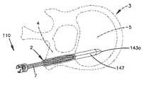
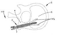
임플란트 또는 고정구(10, 10')는 척추경 스크류 용례를 위해 설계되고, 예를 들어 5, 6 및/또는 7 밀리미터(5, 6 및/또는 7 mm) 척추경 스크류와 같은 상이한 치수의 척추경 스크류를 위해 상이한 직경으로 공급될 수 있다. 임플란트(10, 10')는 약 10 밀리미터(10 mm) 내지 약 60 밀리미터(60 mm)의 길이(L), 바람직하게는 대략 20 밀리미터(20 mm)의 근위부(30, 30') 및 대략 20 밀리미터(20 mm)의 원위부(40, 40')를 갖는 대략 40 밀리미터(40 mm)의 길이일 수 있다. 뼈 증강 고정구(10, 10')는 바람직하게는 추골(3)의 척추경(4) 내에 삽입되어, 뼈가 주로 피질골인 척추경 영역 내에 근위부(30, 30')가 위치되고 바람직하게는 원위부(40, 40')는 뼈가 주로 해면골인 추골체(5) 내로 연장하여 그 내에 위치되게 된다. 임플란트(10, 10')의 다른 길이가 이용될 수 있고, 상이한 근위 및 원위 길이부가 이용되어 상이한 치수의 추골(3)이 치료될 수 있게 된다.Implants or
근위부(30, 30')는 바람직하게는 완전히 탈미네랄화되어 연성, 가요성, 탄성 및 이완성이 된다. 근위부(30, 30')는 또한 바람직하게는 얇아서, 근위부(30, 30') 내로 및 이들을 통한 삽입시에, 척추경 스크류가 척추경(4)의 벽 내로 슬리브(20, 20')를 가압하여 척추경 벽 상에 과도한 응력을 부과하지 않고 뼈 스크류의 증가된 퍼처스 및 고정을 제공하게 한다. 바람직하게는, 스크류가 삽입될 때 어떠한 축방향 힘도 임플란트에 인가되지 않거나 최소의 축방향 힘이 임플란트에 인가되고, 바람직하게는 적어도 근위부 내의 임플란트는 척추경 스크류에 의한 척추경 파괴 후에 스크류로부터 신경 요소를 보호할 수 있는 보호 외장으로서 작용할 수 있다. 스크류가 회전할 때, 제 1의 몇몇 스크류가 연성 동종 이식 고정구 내로 맞물려서, 척추경(4)의 벽 내에 고정구의 근위부를 고정한다. 바람직하게는, 스크류 삽입의 방향에서 고정구의 임의의 잠재적인 운동은 척추경 내의 근위 단부의 초기 고정에 의해 제한되고 그리고/또는 회피된다.The
제 2 바람직한 실시예에서, 뼈 고정구(10')는 근위 단부(33')에서의 립과 같은 돌출부(23)(도 1c 및 도 8에 도시됨)를 포함한다. 립 또는 돌출부(23)는 바람직하게는 근위부(30')의 외경을 넘는 연장부, 숄더 또는 플랜지를 생성하여, 스크류(7)가 삽입될 때 립(23)이 고정구가 추골(3) 내로 원위측으로 병진 이동하는 것을 저지하게 된다. 립(23)은 완전 원통형 섹션, 부분 섹션 또는 소형 탭의 형태를 취할 수 있다.In a second preferred embodiment, the bone fixture 10 'includes a protrusion 23 (shown in FIGS. 1C and 8), such as a lip at the proximal end 33'. The lip or
제 2 바람직한 실시예에서, 도 1b 내지 도 1c에 도시된 탭(23)이 슬리브(20') 상에 제공된다. 탭(23)은 도 1b에 도시된 바와 같이, 슬리브(20')의 동종 이식 뼈 조직의 단일체 연장부로서 직선 상태로 제조된다. 재료는 바람직하게는 탈미네랄화된 동종 이식 뼈이기 때문에, 탭(23)은 바람직하게는 가요성이다. 스크류(7)의 이식 전에, 스크류 고정구(20)가 준비된 구멍 내에 위치되고, 탭부(23)는 가능하게는 유지 슬리브 또는 겸자에 의해 만곡되어(도 1c), 만곡된 탭(23)이 척추경(4)의 외부 부분 상에 놓이게 된다. 유지 슬리브형 기구, 겸자 또는 송곳형 기구가 척추경(4)의 외부벽으로 탭(23)을 약간 하강하여 핀 고정하는데 사용될 수 있다. 일단, 고정구(20')가 적소에서 탭(23)을 사용하여 고정되면, 척추경 스크류가 이식된다. 탭(23)은 바람직하게는 이 방향에서 스크류(7)의 운동의 결과로서 척추경 구멍 내로의 스크류 고정구(20')의 임의의 내향 운동을 저지한다. 탭(23)은 바람직하게는 고정구가 척추경(4) 내에 정확하게 위치되어 스크류(7)와 함께 축방향으로 이동하지 않는 것에 대한 외과의사를 위한 시각적 지시기를 제공한다.In a second preferred embodiment, the
바람직한 실시예에서, 임플란트(10, 10')의 원위부(40, 40')는 바람직하게는 근위부(30, 30')보다 두꺼워, 척추경 스크류(7)가 원위부(40, 40') 내로 연장할 때, 원위부(40, 40')가 추골체(5)의 해면부 내에서 팽창하여 뼈 내의 임플란트(10, 10')의 웨징 기능을 수행하게 한다. 척추경 스크류(7)는 바람직하게는 원위부(40, 40') 내로 연장하고, 원위부(40, 40')의 길이로 연장될 수 있고, 임플란트(10, 10')의 원위 단부(43, 43')로 연장될 수 있다. 대안적으로, 임플란트는 원위부가 척추경(4) 내에 전적으로 위치되고 추골체(5)의 해면부 내로 연장되지 않도록 하는 길이를 가질 수 있다.In a preferred embodiment, the
임플란트가 추골체 내로 연장하기에 충분한 길이를 갖는 실시예에서, 원위부(40, 40')는 바람직하게는 해면골 내에서 근위부(30, 30')보다 많이 팽창하고, 바람직하게는 임플란트(10, 10') 및 척추경 스크류(7)가 추골(3)로부터 견인되는 것을 저지하도록 근위부(30, 30')가 위치되는 척추경 영역(4) 내의 개구보다 큰 크기로 팽창할 것이다. 원위부(40, 40')는 선택적으로 추골 내로의 임플란트의 웨징을 지원하기 위해 원위부(40)의 팽창을 용이하게 하는 슬롯(즉, 임플란트로부터 제거된 재료) 또는 슬릿(즉, 벽 내의 절결부)을 포함할 수 있다. 슬롯(42, 42') 또는 슬릿은 벽(15)을 통해 완전히 또는 부분적으로 연장될 수 있고, 벽(15, 15')의 내부면 또는 외부면 상에 있을 수 있다. 슬롯 또는 슬릿은 임플란트 또는 고정구(10, 10')의 가요성 및 그 팽창 능력을 증가시키기 위해, 벽(15, 15')의 전체 두께를 통해 연장하지 않는 홈 또는 벽(15, 15') 내의 천공부 또는 다른 특징부의 형태를 취할 수 있다.In embodiments where the implant has a length sufficient to extend into the vertebral body, the
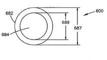
바람직한 실시예에서, 원위부(40, 40')는 실질적으로 균일한 팽창 또는 팽윤, 바람직하게는 원위부의 중간부에서의 실질적으로 균일한 팽창 또는 팽윤을 경험한다. 원위부의 실질적으로 균일한 팽윤 또는 팽창을 용이하게 하기 위해, 슬리브(20, 20')의 원위 단부(43, 43')는 그 인접부, 바람직하게는 실질적으로 원위부(40, 40')의 모든 잔여부보다 얇을 수 있다. 즉, 슬리브 벽(15, 15')은 그 인접 섹션과 비교하여 원위 단부(43, 43')에서 얇아진다. 바람직하게는, 원위 단부(43, 43')는 약 0.5 밀리미터(0.5 mm) 내지 약 1 밀리미터(1 mm), 바람직하게는 약 0.9 밀리미터(0.9 mm)의 벽 두께(18, 18')를 갖는다. 원위 단부 섹션(43, 43')은 바람직하게는 근위부(30, 30')의 벽 두께와 대략 동일한 벽 두께(18, 18')를 갖는다. 원위 단부 섹션(43, 43')은 대략 3 밀리미터(3 mm)의 길이일 수 있고, 바람직하게는 도 2에 도시된 바와 같이 슬리브(20, 20')의 원위부(40, 40') 내에 형성된 선택적인 슬롯, 슬릿 및/또는 홈(42, 42')과 중첩된다. 제 1 및 제 2 바람직한 실시예에서, 두꺼운 원위부(40, 40')로부터 얇은 원위 단부 섹션(43, 43')으로의 전이부(44, 44')가 존재하고, 더 바람직하게는 벽 두께(18, 18')는 약 45도(45°) 내지 약 70도(70°), 더 바람직하게는 약 60도(60°)의 각도에서 존재한다. 벽 두께(18, 18')의 추가의 전이부(41, 41')가 바람직하게는 얇은 근위부(30, 30')와 두꺼운 원위부(40, 40') 사이에 발생될 수 있고, 벽 두께는 약 45도(45°) 내지 약 70도(70°), 더 바람직하게는 약 60도(60°) 각도에서 전이할 수 있다. 벽 두께 전이부에 대한 다른 각도 및 위치가 벽 두께(18, 18')의 다수의 전이부와 같이 고려된다.In a preferred embodiment, the
도 1a 내지 도 1c 및 도 2를 참조하면, 슬리브(20, 20')는 특히 척추경 스크류 삽입을 증강하고 추골(3) 내에 고정하기 위해, 뼈 증강 디바이스 또는 뼈 고정구(10, 10')로서 그리고 척추경 스크류 고정을 위한 시스템의 부분으로서 유용하다. 슬리브(20, 20')는 추골(3) 내의 척추경 스크류(7)의 퍼처스 또는 유지 강도를 증가시키도록 의도되고, 골다공증 뼈 내에서 특정 용례를 발견할 수 있다. 뼈 증강 디바이스는 또한 교정 수술에서 큰 직경 스크류를 사용할 필요성을 회피하고 또는 주어진 수술 절차 및 뼈에 적절한 최대 직경 스크류의 퍼처스를 향상시키는데 사용될 수 있다. 사용시에, 추골(3) 내에 삽입될 척추경 스크류(7)의 외경에 대략 대응하는 개구 또는 보어가 추골(3)의 척추경(4) 내에 형성된다. 뼈 내의 개구, 구멍 또는 보어는 예를 들어 드릴 바이트, 투관침, 외경을 증가시키는 일련의 확장기 등의 사용과 같은 현재 공지되거나 미래에 발견될 방법에 의해 형성될 수 있다. 적절한 치수의 고정구(10)가 뼈 내의 개구 내로의 삽입을 위해 제공되고 선택된다. 고정구(10)는 이용될 척추경 스크류(7)의 크기에 기초하여 선택되고, 바람직하게는 척추경(7)의 샤프트의 직경과 대략 동일하거나 작은 근위부(30, 30') 및 원위부(40, 40') 내의 내경(19, 19')을 갖는다. 고정구(10, 10')는 또한 적절한 길이를 갖도록 선택되고, 바람직하게는 원위부(40, 40')의 대부분을 통해, 더 바람직하게는 실질적으로 슬리브(20, 20')의 전체 길이를 통해 슬리브의 원위부(40, 40') 내로 연장되도록 하는 길이를 바람직하게 갖는다. 슬리브의 길이는 바람직하게는 해면골이 위치되는 추골체(5) 내로 연장되도록 선택되지만, 대안적으로 슬리브는 추골의 척추경(4) 내에 전적으로 위치될 수 있다. 일 예에서, 척추경 스크류(7)는 40 밀리미터(40 mm) 샤프트를 가질 수 있고, 슬리브는 대략 40 밀리미터(40 mm)일 수 있다. 다른 길이의 스크류(7) 및 슬리브(20, 20')가 고려된다.Referring to FIGS. 1A-1C and 2, the
선택된 고정구(10, 10')는 뼈 내에 형성된 개구 내에 삽입되어, 근위부(30, 30')의 근위 단부(33, 33')가 뼈 내에 형성된 개구의 시작부와 실질적으로 동일 높이이거나 동등하게 되고, 원위부(40, 40')가 뼈 내에 위치되고, 바람직하게는 추골체(5)의 해면 영역 내로 연장된다. 척추경 스크류(7)는 스크류(7)를 스크류 조임함으로써, 즉 회전시킴으로써 슬리브(20, 20') 내에 삽입되어, 스크류(7)의 원위 단부가 슬리브(20, 20')의 근위부(30)를 통해 연장하여 이동하게 된다. 스크류(7)가 슬리브(20, 20')의 근위부(30, 30')를 통해 이동할 때, 슬리브(20, 20')는 바람직하게는 뼈 내의 개구를 둘러싸는 척추경(4)의 벽 내로 팽창하고 가압되어 간섭 끼워맞춤이 슬리브 벽(15, 15')과 뼈 사이에 형성되게 된다. 스크류(7)가 슬리브(20, 20') 내에 더 삽입될 때, 척추경 스크류(7)의 원위 단부는 슬리브(20, 20')의 더 두꺼운 원위부(40, 40')에 진입하고, 바람직하게는 추골체(5)의 해면골 내로 슬리브(20, 20')의 원위부(40, 40')를 팽창시킨다. 원위부(40, 40')는 바람직하게는 근위부(30, 30')보다 많이 팽창하고, 바람직하게는 뼈의 척추경 영역(4) 또는 근위부 내의 개구보다 큰 크기로 팽창하고, 더 바람직하게는 뼈 내에 웨징 효과, 더 바람직하게는 뼈(7) 내의 뼈 스크류의 유지 강도를 증가시키는 것을 지원하기 위한 플러그로서 작용하는 팽윤 효과를 원위부(40, 40') 내에 생성한다. 스크류(7)가 슬리브(20, 20') 내에 삽입되어 하강할 때, 슬리브(20, 20')는 바람직하게는 스크류의 방향에서 구멍에서 축방향으로 하강 이동하지 않는다.The selected
사용시에, 슬리브(20, 20')의 원위부(40, 40')는 팽창할 때 절단될 수 있어 원위 단부 섹션(43, 43')이 슬롯(42, 42')의 원위 단부에서 찢어지게 된다. 사용시에, 슬롯(42, 42')과 개구(45, 45') 사이의 원위 단부 섹션(43, 43')의 영역은 원위부(40, 40')의 추가의 팽창을 허용하도록 길이 방향 방식으로 찢어지거나 파열될 수 있고, 바람직하게는 하나 이상의 핑거로 원위부를 분리할 수 있다. 원위 섹션(43, 43')의 얇은 섹션은 바람직하게는 원위부(40, 40')의 균일하고 대칭적인 팽윤 및 팽창을 용이하게 하고, 다수의 핑거를 생성하기 위해 하나 이상의 슬롯(42, 42')의 원위 단부(46, 46')와 개구(45, 45') 사이의 원위 섹션(43, 43')의 찢어짐을 용이하게 할 수 있다. 다수의 슬롯(42, 42')에 인접한 원위 단부(43, 43') 내의 고정구(10, 10')의 이 찢어짐 또는 파괴는 바람직하게는 원위 섹션이 원위부(40, 40')의 두꺼운 부분만큼 두껍게 잔류되는 경우보다 더 균일하고 대칭적인 만곡, 팽윤 및 팽창과 핑거의 형성을 용이하게 한다.In use, the
근위부(30)는 선택적으로 슬리브(20, 20')의 근위 단부(33, 33') 직전에서 종료하는 종축을 따른 복수의 종축, 슬릿 홈 또는 천공부(미도시)를 포함할 수 있다. 예를 들어, 슬롯 또는 슬릿은 근위부(30, 30')의 중공 내부벽(14, 14')을 도중 내내 통하는 근위부(30, 30')의 외부벽면(13, 13')으로부터 형성될 수 있다. 슬릿은 대안적으로 외부벽면(13, 13')으로부터 반경방향으로 연장되지만, 근위부(30, 30')의 중공 내부벽(14, 14')에 도달하기 전에 종료한다. 슬릿은 또한 내부벽(14, 14')으로부터 외부벽(13, 13')을 향해 반경방향으로 연장될 수 있지만, 근위부(30, 30')의 외부벽(13, 13')에 도달하기 전에 종료하거나 중단된다. 슬릿 또는 슬롯은 또한 벽(15, 15') 내에 랜덤하게 형성되거나 또는 패턴으로 정렬될 수 있는, 벽(15, 15')을 관통하거나 부분적으로 관통하는 일련의 또는 복수의 구멍을 포함하는 천공부의 형태를 취할 수 있다.The
도 1a 내지 도 1c 및 도 2의 임플란트(10)를 참조하여 설명된 방법 및 특징의 다수는 또한 본 명세서에 설명되고 도시된 다른 실시예, 특히 도 3 내지 도 14의 실시예에도 적용될 것이다. 도 3a 내지 도 3d는 뼈 증강 또는 고정 디바이스의 상이한 바람직한 실시예를 도시한다. 도 3의 뼈 증강 디바이스(110)는 바람직하게는 완전히 또는 부분적으로 탈미네랄화된 동종 이식 뼈 조직으로부터 형성되고, 바람직하게는 종축(112)을 갖는 대략 원통형 튜브 또는 슬리브(120)를 형성한다. 뼈 증강 디바이스(120)는 근위부(130) 및 원위부(140)를 갖는다. 근위부(130)는 바람직하게는 완전히 탈미네랄화된 뼈(예를 들어, 적어도 80% 탈미네랄화됨)로 형성되고, 근위 개구(135)와 연통하는 중공 캐비티 또는 통로(125)를 갖는다. 중공부의 내경(119)은 바람직하게는 뼈 증강 디바이스(110)를 통해 그 내로 삽입되도록 의도된 뼈 스크류의 직경과 실질적으로 동일하거나 약간 작다. 뼈 증강 디바이스(110)의 근위부(130) 및 원위부(140)는 바람직하게는 완전히 탈미네랄화된다(예를 들어, 적어도 80% 탈미네랄화됨). 대안적으로, 증강 디바이스(110)의 근위부(130)는 완전히 탈미네랄화될 수 있고, 원위부(140)는 부분적으로 탈미네랄화되거나 탈미네랄화되지 않아 근위부(130)가 원위부(140)보다 더 연성이 되고 더 가요성이 되게 할 수 있다.Many of the methods and features described with reference to the
근위부(130)는 바람직하게는 임플란트의 근위 단부(133)의 직전에서 종료하는 종축(112)을 따라 형성된 슬릿, 슬롯, 홈 또는 천공부(42)와 유사한 복수의 슬릿, 슬롯, 홈 또는 천공부(136)를 포함한다. 도 3의 임플란트(110)는 6개의 슬릿(136)을 갖고 도시되어 있지만, 더 많거나 적은 슬릿이 원하는 바에 따라 이용될 수 있다. 슬릿(136)은 임플란트(110)의 벽(115)을 통해 부분적으로 또는 전적으로 연장될 수 있지만, 도 3의 바람직한 실시예의 슬릿(136)은 슬리브(120)의 외부면(113)으로부터 내부벽면(114)을 향해 벽(115)을 통해 단지 부분적으로만 연장된다. 근위부(130)는 도 1a 내지 도 1c 및 도 2의 실시예에 대해 전술된 바와 같은 벽 두께(18), 외경 및 내경(17, 19) 및 길이를 가질 수 있다. 슬리브(120)의 총 길이(L3) 및 근위부(130) 및 원위부(140)의 길이는 도 1a 내지 도 1c 및 도 2의 실시예에 대해 전술된 바와 같이 동일한 길이를 가질 수 있다.
도 3의 실시예의 동종 이식 임플란트(110)의 원위부(140)는 바람직하게는 중실형이지만, 근위부(130)에 굴곡 가능하게 연결될 수 있다. 원위부(140)는 바람직하게는 원위부의 일 측면으로부터 원위부의 대향 측면으로 바람직하게는 도중 내내 연장하는 하나 이상의 슬릿(147)을 포함한다. 도 3의 실시예에서, 2개의 관통 슬릿(147)이 원위부(140)를 따라 90도(90°) 이격하여 배치되어, 관통 슬릿(147)의 각각의 단부가 다음의 관통 슬릿(147)으로부터 90도(90°) 이격하여 배치되어 십자선 패턴을 형성하게 된다. 도 3의 실시예의 원위부(140)는 근위부(130)에 굴곡 가능하게 연결된 4개의 팽창 가능한 핑거(147a)를 형성하는 2개의 관통 슬릿을 갖고 도시되어 있지만, 더 많거나 적은 관통 슬릿(147)은 근위부에 굴곡 가능하게 연결된 더 많거나 적은 팽창 가능한 핑거(147a)를 형성하기 위해 근위부(140) 내에서 상이한 배향, 길이 및 깊이로 포함될 수 있다. 대안적으로, 원위부(140)는 또한 근위부(130)를 특징화하는 캐뉼레이션보다 직경이 작은 캐뉼레이션을 바람직하게 갖는 중공 캐비티를 가질 수 있다. 게다가, 원위부(140) 내의 캐뉼레이션의 직경은 근위부(130) 내의 캐뉼레이션의 직경과 대략 동일할 수 있다. 캐뉼레이션된 원위부를 갖는 이 대안적인 실시예는 도 5d 내지 도 5f와 유사할 수 있다. 캐뉼레이션된 근위 및/또는 원위부(130, 140)의 내부는 또한 척추경 스크류(7)의 맞물림을 지원하기 위해 탈미네랄화될 수 있다.The distal portion 140 of the
제 3의 바람직한 실시예의 임플란트(110)의 원위 단부(143)는 용이한 삽입을 위한 날카로운 또는 무딘 단부(143a)를 포함할 수 있다. 바람직하게는, 슬리브(120)의 근위 및/또는 원위부(130, 140)의 외부면(113)은 동종 이식 임플란트(110)와 주위 뼈 사이의 파지력을 향상시키기 위한 표면 질감부를 포함할 수 있다. 일 실시예에서, 근위부(130)의 원위 단부는 플런저 또는 푸시 로드와 같은 삽입 기구가 추골(3) 내로의 임플란트(110)의 삽입 중에 근위부(130)의 근위 단부(133)에 대해 지지되게 될 수 있도록 경사진 에지(131)[도 1의 에지(31) 참조]를 선택적으로 포함할 수 있다. 경사진 에지(131)는 또한 척추경 스크류(7)를 위치시키고 척추경 스크류를 시작하는 것을 지원하기 위한 모따기부(131) 내의 안내부로서 작용할 수 있다. 또한, 근위부(130) 및 원위부(140)의 양자 모두는 동일한 동종 이식 조직 형으로부터 단일체로 형성될 수 있다. 근위부 및 원위부는 대안적으로 개별 동종 이식 뼈 조각으로부터 가공될 수 있고, 그 후에 이하에 더 상세히 설명되는 바와 같이 바람직하게는 동종 이식 뼈 조각에 의해 굴곡 가능하게 연결되는 조각들 사이의 이동을 허용하도록 함께 결합될 수 있다.The
작동시에, 도 3b를 참조하면, 임플란트(110)는 바람직하게는 투관침 또는 플런저 로드와 같은 기구(50)를 사용하여 척추경(4)을 통해 골다공증 추골체(5)일 수 있는 것 내로 연장하는 미리 형성된 구멍(2) 내에 삽입된다. 뼈 증강 디바이스와 연계하여 사용된 적합한 삽입 기구가 도 8을 참조하여 상세히 논의된다. 임플란트(110)는 바람직하게는 뼈 내에 삽입되어, 바람직하게는 근위 단부(133)가 뼈 내의 개구(2)와 비교적 동일 높이가 되고 동등하게 된다. 척수경 스크류(7)는 다음에 바람직하게는 도 3c에 도시된 바와 같이 임플란트(110)를 통해 추골(3) 내에 삽입된다. 척수경 스크류(7)가 슬리브(120)를 통해 전진할 때, 동종 이식 슬리브(120)의 근위부(130)를 따라 배치된 슬릿(136)이 확산 이격되고 바람직하게는 실질적으로 전체 근위부(130)가 척수경(4) 내의 채널 내에서 반경방향으로 팽창되게 하고, 도 3c에 도시된 바와 같이 근위부(130)가 배치되는 척추경(4) 내로 맞물림을 제공하게 된다. 바람직한 실시예에서, 척추경 스크류(7)의 스크류 쓰레드(screw thread)들은 바람직하게는 근위부(130)의 중공 내부벽면(114) 내에 스크류 쓰레드가 형성되도록 더 연성의 근위부(130)를 변형시킨다.In operation, referring to FIG. 3B, the
척추경 스크류(7)가 임플란트를 통해 전진하고 원위부(140)의 내부에 접촉할 때, 원위부(140)는 도 3d에 도시된 바와 같이 그를 통해 형성된 슬릿(147)을 경유하여 이격 분할되고, 존재할 수 있는 해면골 내로 가압되고, 스크류(7)와 척추경(4)의 후방벽 사이에 웨지를 형성하여, 척추경 스크류(7)에 대한 추가의 견인 저항을 제공한다. 동종 이식 슬리브(120)의 원위측 팽창된 원위부(140)와 슬리브(120)의 반경방향 팽창된 근위부(130)는 바람직하게는 주위뼈 내로의 척추경 스크류(7)의 퍼처스를 향상시키고, 바람직하게는 척추경 스크류 철수(backout) 및 토글링의 가능성을 감소시킨다.When the
PMMA, 칼슘 포스페이트 시멘트 등과 같은 생체 적합성 재료가 예를 들어, 척추경 스크류의 원위 단부를 통해, 임플란트 및/또는 척추경 스크류의 원위부를 따라, 또는 여전히 액체 상태에서 임플란트의 전체 내부를 따라 동종 이식 임플란트(110) 및 척추경 스크류(7) 배치와 함께 사용될 수 있다.Biocompatible materials, such as PMMA, calcium phosphate cement, etc., may be used, for example, through the distal end of the pedicle screw, along the distal portion of the implant and / or pedicle screw, or along the entire interior of the implant in the still liquid state. 110 and pedicle screw 7 arrangements.
도 4a 내지 도 4c는 바람직하게는 완전히 탈미네랄화되는(예를 들어, 적어도 80% 탈미네랄화됨) 동종 이식 튜브 또는 슬리브(220)의 형태의 뼈 증강 디바이스(210)의 다른 바람직한 실시예를 도시한다. 슬리브(220)는 완전히 탈미네랄화되는 것이 바람직하지만, 슬리브는 부분적으로 탈미네랄화되고, 탈미네랄화를 갖지 않고, 또는 슬리브(220)의 중간부와는 상이한 정도로 완전히 또는 부분적으로 탈미네랄화된 내부면 및 외부면을 가질 수 있다. 동종 이식 튜브(220)는 바람직하게는 종축(212)을 포함하고, 슬리브(220)가 근위 및 원위 개구(235, 245)를 갖는 그 전체 길이 전체에 걸쳐 중공형이 되도록 중앙 보어(225)를 갖는다. 동종 이식 튜브 또는 슬리브(220)는 제 2 바람직한 실시예의 립(23)과 유사한 기능을 하는 립(미도시)을 그 근위 단부(233)에 추가로 포함할 수 있다.4A-4C show another preferred embodiment of a
작동시에, 바람직하게는, 완전히 탈미네랄화된 동종 이식 슬리브(220)는 바람직하게는 추골체(5)의 내부 내로 척추경(4)을 통해 미리 형성된 구멍 내로 삽입된다. 동종 이식 슬리브(220)는 바람직하게는 동종 이식 슬리브의 근위 단부(233)가 도 3b 내지 도 3d의 실시예에서 슬리브(120)에 대해 도시된 바와 같이 척추경(4)의 외부면과 동일 높이에 놓이도록 삽입된다. 척추경 스크류(7)는 바람직하게는 동종 이식 슬리브(220) 및 주위 척추경 및 추골을 통해 삽입되고, 척추경 스크류가 추골체(5)의 내부를 향해 전진할 때, 동종 이식 임플란트(210)의 탈미네랄화된 뼈 재료는 척추경(4)과 해면골에 의해 특징화될 수 있는 추골체(5)의 내부로 가압된다.In operation, preferably, the fully
동종 이식 임플란트의 탈미네랄화 성질은 바람직하게는 동종 이식 임플란트의 골 유도성 잠재력을 향상시키고, 동종 이식 슬리브(220)를 통한 척추경 스크류(7)의 전진으로부터 발생하는 스크류, 동종 이식 임플란트 및 척추경(4)의 벽 사이의 간섭 끼워맞춤은 척추경 스크류의 견인 강도를 증가시킨다. 대안적으로, 동종 이식 슬리브(20)는 동종 이식 슬리브(220)의 외부 및/또는 내부면 상에서 단지 부분적으로 탈미네랄화될 수 있다. 동종 이식 슬리브(220)의 근위 및/또는 원위부의 외부면(213)은 동종 이식 슬리브(220)와 주위 뼈(3) 사이의 퍼처스를 향상시키기 위한 표면 질감부를 포함할 수 있다.The demineralized nature of the allograft implant preferably enhances the bone inducible potential of the allograft implant and results from the advancement of the
동종 이식 슬리브(220)는 부분적으로 탈미네랄화되는 원위부(240)와, 완전히 탈미네랄화되는 근위부(230)를 포함할 수 있다. 작동시에, 척추경 스크류(7)는 바람직하게는 동종 이식 슬리브(220)의 근위부(230) 내의 완전히 탈미네랄화된 더 연성의 동종 이식 뼈의 존재가 여전히 그 내부의 그 위치에 고정하기 위한 충분한 맞물림을 제공하는 사실에 기인하여 척추경(4) 내에 용이하게 전진한다. 척추경 스크류(7)가 추골체(5)의 후방벽을 넘어 동종 이식 튜브(22)의 원위부(240) 내로 전진할 때, 동종 이식 슬리브(220)의 더 강하고 더 두꺼운 뼈는 팽창되고 그리고/또는 추골체의 해면 코어일 수 있는 것 내로 확산된다. 동종 이식 슬리브(220)의 근위 및/또는 원위부의 외부면(213)은 동종 이식 슬리브(220)와 주위 뼈 사이의 퍼처스를 향상시키기 위해 표면 질감부를 포함할 수 있다. 동종 이식 슬리브의 원위 단부(243)는 예를 들어 동종 이식 핀(미도시)으로 교차 핀 고정될 수 있어 동종 이식 슬리브의 삽입을 용이하게 하는 것을 지원한다. 교차 핀 고정은 또한 C-아암 상의 임플란트의 가시성을 향상시킬 수 있다.The
동종 이식 튜브 또는 슬리브(220)는 대안적으로 근위 개구(235)로부터 원위 개구로 연장하는 중앙 보어(225) 및 종축을 포함하고, 따라서 슬리브(220)는 그 전체 길이 전체에 걸쳐 중공형이다. 튜브(220)는 튜브(220)의 중간 섹션에서 종축(212)의 방향으로 연장하는 하나 이상의 길이 방향 슬릿, 슬롯, 홈 또는 천공부(247)를 포함할 수 있다. 바람직하게는, 슬릿(247)은 외부면(213)으로부터 내부벽면(214)으로 튜브벽(215)을 통해 연장된다. 슬릿(247)은 바람직하게는 슬리브(220)의 전체 길이로 연장하지 않고, 바람직하게는 원위 단부(243) 또는 근위 단부(233)로 연장되지 않는다. 바람직하게는, 연속적인 링 섹션(239)이 근위 단부(233)에 형성되고, 연속적인 링 섹션(251)이 원위 단부(243)에 형성된다. 연속적인 링 섹션(239, 251)은 바람직하게는 약 2 밀리미터(2 mm) 내지 약 10 밀리미터(10 mm)의 길이, 더 바람직하게는 약 3 밀리미터(3 mm) 내지 약 7 밀리미터(7 mm)의 길이이다. 링 섹션(239, 251)에서의 벽면(215)은 바람직하게는 연속적이고 슬릿(247)에 의해 중단되지 않는다. 링 섹션(239, 251)은 바람직하게는 스크류의 삽입시에 손상되지 않고 유지된다. 슬릿 또는 그 적어도 일부를 포함하는 튜브(220)의 중간 섹션은 바람직하게는 연속적인 링 섹션(239, 251)보다 두껍다.The allograft tube or
튜브(220)의 외경(217)은 바람직하게는 뼈 내에 준비된 구멍 내에 끼워지도록 선택되고, 반면에 튜브(220)의 내경(219)은 스크류(7)를 수용한다. 링 섹션(239, 251)의 내경(219)은 바람직하게는 중간 섹션보다 크고, 바람직하게는 스크류(7)의 외경과 대략 동일한 크기일 수 있어 스크류(7)가 링 섹션(239, 251)의 비교적 적은 팽창으로 삽입될 수 있어 링 섹션(239, 251)이 바람직하게는 손상되지 않고 유지되게 한다. 슬리브(220)의 중간 섹션의 내경(219)은 바람직하게는 도 4c에 도시된 바와 같이 스크류가 슬리브(220)에 삽입 하강되어 중간 섹션을 팽창시킬 때 스크류와 간섭한다. 즉, 스크류(7)가 중간 섹션으로 하강 진행할 때, 도 4c에 도시된 바와 같이 스크류(7)가 팽창하고 슬릿(247)이 확장된다. 중간 섹션의 팽창은 뼈 내의 스크류(7)의 유지 강도 및 퍼처스를 향상시키고, 바람직하게는 스크류(7)를 추골(3) 내에서 전이(shift)시킬 수 있는 스크류(7)의 토글링을 저지하거나 방지한다.The outer diameter 217 of the
도 4a 내지 도 4c의 실시예는 내부면(214)으로부터 외부면(213)으로 전체 벽 두께를 통해 연장하는 슬릿(247)을 이용하는 것으로서 도시되고 설명되었지만, 단지 부분적으로 벽(215)을 통해 연장하는 슬릿이 사용될 수 있고, 슬릿(247)은 개방 슬롯, 홈 또는 천공부를 포함할 수 있다. 게다가, 튜브 또는 슬리브(220)가 동종 이식편 및 바람직하게는 적어도 부분적으로 탈미네랄화된 동종 이식편의 형태인 것으로서 설명되었지만, 슬리브(220)는 금속, 금속 합금, 세라믹, 복합 재료 및 예를 들어 PEEK, PTU, PET, EVA, PCU 또는 다른 생체 적합성 또는 생체 흡수성 플라스틱과 같은 플라스틱을 포함하는 임의의 생체 적합성 재료로 형성될 수 있고, 본 출원의 다른 실시예는 또한 이들 상이한 재료로 구성될 수도 있다.Although the embodiment of FIGS. 4A-4C is shown and described as using a
도 5a 내지 도 5c는 도 4의 실시예에 설명된 동종 이식 슬리브의 디자인의 수정예를 도시하고, 여기서 원위부(240)가 에칭되거나 홈 형성되어 원위부(240)의 동종 이식편을 분할선(249)을 따라 약화시키거나 스트립으로 완전히 절단하여, 척추경 스크류(7)가 동종 이식 튜브(220)의 원위 내부를 통해 전진할 때 원위부(240)가 분할 개방되어, 이에 의해 견인을 더 저지하거나 방지하게 된다. 도 4 및 도 5의 실시예는 단일편의 동종 이식 조직으로부터 단일체로 형성될 수 있고, 또는 대안예에서 개별 동종 이식편으로부터 형성되어 이후에 함께 결합될 수 있다.5A-5C illustrate a modification of the design of the allograft sleeve described in the embodiment of FIG. 4, where the
도 5d 및 도 5e는 도 4 및 도 5a 내지 도 5c의 디자인에 대한 다른 실시예를 도시한다. 뼈 증강 디바이스(210')는 근위 단부(233)에 개구(235)를 형성하는 벽(215)을 갖는 근위측 연속 링 섹션(239)을 갖는다. 개구(233)는 중공 캐비티(225)와 연통한다. 바람직하게는, 복수의 스트립(253)이 링 섹션(239)의 벽으로부터 원위측으로 연장한다. 뼈 증강 디바이스(210')는 바람직하게는 단일체이고, 얇은 스트립(253)을 형성하기 위해 원위부에서 모두 슬리브로 절단되는 복수의, 본 예에서는 8개의 슬릿(249)을 갖는 연속적인 원통형 벽을 구비하는 중공의 원통형 형상의 단일체 튜브 또는 슬리브로부터 형성될 수 있다. 슬릿(249)은 도시된 바와 같이 슬리브(220)의 근위부(230) 내로 연장될 수 있다. 슬릿(249)은 바람직하게는 결합되지 않은 스트립을 형성하기 위해 내부벽면(213)으로부터 외부벽면으로 연장된다. 대안적으로 또는 추가적으로, 슬릿(249)은 단지 벽(215)을 통해 부분적으로 연장될 수 있고, 스크류가 슬리브(220)로 전진 하강할 때 찢어져서 탈착될 수 있다.5D and 5E show another embodiment of the design of FIGS. 4 and 5A-5C. The
도 6a 내지 도 6c는 뼈 증강 디바이스(310) 및 그 제조 방법의 다른 실시예를 도시한다. 뼈 증강 디바이스(310)는 바람직하게는 2개 조각(360, 370)으로부터 형성되고, 그 조립 형태에서 일반적으로 원통형 세장형 부재(320)이다. 세장형 부재(320)는 바람직하게는 비교적 두껍고 강성인 원위부 또는 부품(340) 및 비교적 얇은 근위부 또는 부품(330)을 포함한다. 원위 부품(340)은 링형 근위 단부(362), 간극 또는 공간(363)에 의해 분리된 하나 이상의 핑거(364) 및 커넥터부(365)를 포함한다. 커넥터부(365)는 바람직하게는 핑거(364)를 링형 근위 단부(362)에 연결한다.6A-6C illustrate another embodiment of a
근위 부품(330)은 링형 커넥터 스트립(372)과, 간극 또는 공간(373)에 의해 분리된 하나 이상의 말단부(374)를 포함한다. 커넥터 스트립(372)은 커넥터 스트립(372)으로부터 연장하는 말단부(374)를 연결한다. 근위 부품(330)과 원위 부품(340)의 양자 모두는 바람직하게는 동종 이식 뼈로부터 형성되지만, 다른 재료가 고려된다. 바람직하게는, 양 근위 및 원위 부품(330, 340)은 완전히 또는 부분적으로 탈미네랄화된 뼈로 형성되지만, 근위 부품(330)은 완전히 탈미네랄화되고 원위 부품(340)은 단지 부분적으로만 탈미네랄화된 뼈이고, 원위부(310)는 바람직하게는 근위 부품(330)보다 비교적 강성인 것이 바람직할 수 있다. 근위 부품(330) 및 원위 부품(340)은 각각 바람직하게는 단일편의 뼈로부터 형성되고 이하에 설명되는 바와 같이 함께 연결된다.
바람직하게는, 근위 부품(330)의 벽(315)의 두께(318)는 원위 부품(340)의 벽(315)의 두께(318)보다 작다. 세장형 부재(320)의 내경(319)은 바람직하게는 슬리브(320) 내에 형성된 중공 채널(325)에 하향 삽입되는 척추경 스크류(7)의 외경보다 약간 작거나 같다. 바람직하게는, 홈(361)은 핑거(370)를 링(362)으로부터 분리하여 가요성 커넥터부(365)를 형성한다. 홈(361)의 폭은 부품(330, 340)이 도 6에 도시된 바와 같이 함께 결합될 때 커넥터 스트립(372)의 폭에 적합하기에 충분한 크기이다. 홈 또는 리세스 형성부(336)가 링 섹션(360) 내에 형성되어 근위 부품(330)이 원위 부품(340)에 조립될 때 말단부(374)를 수용한다.Preferably, the
이 바람직한 세장형 부재(320)를 조립하기 위해, 원위 부품(340)의 핑거(364)는 도 6b에 도시된 바와 같이 함께 압착될 수 있다. 핑거(364)가 함께 압착될 때, 커넥터부(365)는 핑거(364)가 함께 근접하여 이동하는 것을 허용하는 가요성 핑거로서 작용한다. 핑거(364)가 압착된 상태에서, 근위 부품(330)이 삽입되어 원위 부품(340) 상에서 활주한다. 핑거(364)는 바람직하게는 간극(373)으로 하향 삽입되고, 말단부(374)는 공간(363)에 대응하고 이 공간을 활주 하강한다. 원위 부품(340) 및 근위 부품(330)은 함께 압박되어, 도 6c에 도시된 바와 같이 핑거(364)가 커넥터 스트립(372)을 지나 연장하고 말단부(374)가 강성 링 섹션(362)을 지나 연장하게 된다. 바람직하게는, 말단부(374)는 링 섹션(362) 내에 형성된 리세스(366)를 통해 연장하여 활주한다. 바람직하게는, 근위 부품(330)의 커넥터 스트립(372)은 커넥터 섹션(365) 내에 형성된 홈(361) 내에 끼워지고, 바람직하게는 원위 부품(340) 내에 고정된다. 동종 이식 뼈의 2개 조각(360, 370)이 함께 조립되어 임플란트(310)를 형성한 후에, 임플란트(310)는 산욕 내에 침지되어 부분(360, 370)을 함께 고정하거나 용접할 수 있다.To assemble this preferred elongate member 320, the
대안적으로, 근위부(330)는 핑거(364)가 간극(373) 내에 끼워지고 말단부(374)가 간극(363)에 끼워지면, 핑거(364)를 압착하지 않고 원위부(340)에 대해 이동하고 원위부(340)에 연결될 수 있다. 이 조립 방법에서, 커넥터부(365)는 바람직하게는 커넥터 스트립(372)이 아암(364) 상에서 활주하고 홈(361) 내에 끼워지는 것을 허용하도록 충분히 가요성일 수 있다.Alternatively, the
도 6a 내지 도 6c의 실시예는 2개의 간극(363)에 의해 분리된 2개의 핑거(364) 및 2개의 간극(373)에 의해 분리된 2개의 말단부(374)를 갖고 설명되고 도시되었지만, 임플란트(310)는 더 많거나 적은 핑거(364) 및 말단부(374)를 포함할 수 있고, 동일하지 않은 수의 핑거 및 말단부(364, 374)가 존재할 수도 있다. 2-부분 뼈 증강 디바이스(310)의 잠재적인 장점은 적절한 크기의 단일편의 뼈보다 채취가 용이할 수 있는 동종 이식 또는 자가 이식 뼈의 2개의 짧은 부분으로부터 형성될 수 있다는 것이다.The embodiments of FIGS. 6A-6C have been described and illustrated with two
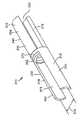
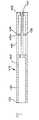
도 7a 내지 도 7c를 참조하면, 슬리브 또는 튜브(420)의 형태의 다른 바람직한 실시예에 따른 뼈 증강 디바이스(410)는 바람직하게는 동종 이식 조직으로 형성되고, 바람직하게는 종축(412) 및 근위 및 원위 단부(433, 443)를 포함한다. 슬리브(420)는 바람직하게는 또한 슬리브(420)의 근위 단부(433) 및 원위 단부(443)가 연속적인 링으로서 잔류하고 중간부가 얇은 스트립(453) 내에 형성되는 방식으로 형성된 복수의 길이 방향 절결부(447)를 포함한다. 슬리브(420)는 바람직하게는 길이 방향 절결부(447)의 형성 후에 부분적으로 또는 완전히 탈미네랄화된다. 스트립(453)의 원위부는 바람직하게는 스트립(453)이 바람직하게는 절첩선을 형성하는 가요성 힌지(438a)로서 바람직하게 기능하는 이들의 중간점에 또는 그 부근에 얇은 섹션(438)을 갖는 방식으로 형성된다. 스트립(453)의 얇은 섹션(438)은 바람직하게는 근위 단부(433)로부터 중공 튜브(420)의 길이의 대략 4분의 3(3/4)에 위치된다.7A-7C, the
작동시에, 도 7b에 도시된 바와 같이 근위 단부(433)가 척추경(4)의 외부와 정렬되고 슬리브(420) 상의 중간 마크가 추골체(5)의 후방벽의 내부에 또는 내부 부근에 정렬될 때까지 푸시로드(50)가 바람직하게는 척추경(4) 내에 중공 슬리브(420)를 삽입하는데 사용된다. 슬리브(420)의 원위 단부(433)는 이어서 바람직하게는 척추경(4)의 외부와 동일 높이의 위치에서 근위 단부(433)를 유지하면서 후방 견인된다. 원위 단부 링 섹션(433)이 근위측으로 견인될 때, 원위부(440)는 도 7에 도시된 바와 같이 힌지(438)에서 절반으로 절첩되고, 특정량의 수축 후에 그 절첩된 위치로 체결된다. 슬리브(420)의 견인 강도는 이에 의해 향상된다.In operation, as shown in FIG. 7B, the
원위 연속링(443)은 다수의 상이한 방식으로 근위부(430)를 향해 후방 견인될 수 있다. 푸셔(50)의 단부는 원위 연속링(443)에 부착될 수 있고, 푸셔(50)는 링(443)을 근위측으로 이동시키도록 수축될 수 있다. 푸셔(50)는 링(443)이 근위측으로 이동하여 힌지(438)가 활성화되고 원위부(440)가 절첩되어 팽창될 때 연속링(443)으로부터 분리될 수 있다. 슬리브(420)의 원위 연속링(443)은 대안적으로 내부 스크류 쓰레드(미도시)를 포함할 수 있다. 내부 스크류 쓰레드는 푸셔(50)를 원위 연속링(443)에 연결하기 위해 푸셔(50)의 원위 단부 상의 스크류 쓰레드와 상호 작용할 수 있다. 푸셔(50)는 이어서 슬리브(420)의 근위 단부(433)를 향해 원위 단부(443)를 수축시키도록 근위측으로 견인된다. 원위 단부(443)가 수축되거나 근위 단부(433)를 향해 후방 견인될 때, 원위부(440)는 힌지(438)에서 절첩되고 원위부(440) 내에서 팽창되어 추골(3) 내에 더 양호한 퍼처스를 제공한다. 푸셔(50)는 이어서 슬리브(420)로부터 분리될 수 있다. 대안적으로, 스크류 쓰레드 형성 로드가 연속링(443) 상에 스크류 쓰레드와 상호 작용함으로써 팽창 가능한 원위부(440)를 전개하는데 사용될 수 있다. 스크류 쓰레드 형성 로드는 스크류 쓰레드 형성 로드의 길이를 따라 근위측으로 링(443)을 이동시키도록 회전될 수 있다. 대안적으로 또는 추가적으로, 원위 연속링(443) 상의 스크류 쓰레드는 슬리브(420) 내에 삽입된 척추경 스크류 상의 스크류 쓰레드와 상호 작용하여 원위부(440)를 수축하고 척추경 스크류가 제 위치로 회전할 때 그 팽창 위치로 이동시킬 수 있다. 추가적으로 또는 대안적으로, 개별 너트(미도시)가 슬리브(420)의 원위 단부에 제공되어 스크류 쓰레드 형성 로드 또는 척추경 스크류(7)와 함께 동작하여 팽창 가능한 원위부(440)를 전개할 수 있다.The distal
도 8은 임플란트, 특히 도 1 내지 7의 임플란트 실시예와 함께 사용하기에 적합한 삽입 기구를 도시한다. 삽입 기구는 푸셔 요소(50)를 거쳐 뼈 증강 디바이스(10, 10', 110, 210, 210', 310, 410)에 단일 압박 또는 플런지 기능을 구현하는 기능을 한다. 푸셔 요소(50)는 바람직하게는 척추경(4) 및 추골체(5) 내에 삽입된 임플란트(10)의 길이를 제한하는 기능을 하는 척추경(4)의 후방벽에 놓이게 되는 정지부(52)를 포함한다. 삽입 기구는 바람직하게는 임플란트, 동종 이식 슬리브, 튜브, 세장형 부재 또는 시임(10, 10', 110, 210, 210', 310, 410)의 정확한 위치 설정을 가능하게 하기 위해 방사선 투과성이다.8 shows an insertion instrument suitable for use with the implant, in particular the implant embodiment of FIGS. 1 to 7. The insertion mechanism serves to implement a single compression or plunge function to the
도 1 내지 도 7의 임플란트는 일반적으로 원통형인 것으로서 도시되고 설명되었지만, 외부 형상 및 내부 보어 형상은 다른 형태를 취할 수 있고, 도시되고 설명된 원통형 형상에 한정되는 것은 아니라는 것이 즉시 이해될 수 있다. 본 발명의 동종 이식 조직 형은 이식 중에 동결 건조 상태에서 사용되고 이어서 원 위치에서 또는 임플란트 절차 중에 재수화되도록 허용될 수 있다. 후방 치형부, 리지, 역방향 지지부, 스크류 쓰레드, 하나 이상의 용골(keel) 또는 다른 표면 질감부가 주위 뼈 내로의 맞물림을 증가시키도록 임플란트(10, 10', 110, 210, 210', 310, 410)의 외부면에 적용될 수 있다. 이쑤시개 또는 성냥과 형상 및 크기가 유사한 완전히 또는 부분적으로 탈미네랄화된 동종 이식 뼈 스틱(미도시)이 척추경 스크류(7)가 삽입되는 척추경 스크류(7)와 주위 뼈 사이의 시임으로서 사용될 수 있다.Although the implants of FIGS. 1-7 are shown and described as being generally cylindrical, it can be readily understood that the outer and inner bore shapes can take other forms and are not limited to the cylindrical shapes shown and described. Allograft tissue types of the invention can be used in a lyophilized state during implantation and then allowed to rehydrate in situ or during an implant procedure.
고정구 또는 시임의 슬릿, 슬롯, 홈, 절결부 또는 천공부의 배향, 위치, 깊이 및 길이는, 팽창의 양 및 위치가 제어될 수 있도록, 예를 들어 원위부의 팽창이 바람직한 평면 내에서 발생할 수 있도록 구성될 수 있다. 방사선 그래픽 마커(미도시)가 임플란트에 추가될 수 있어, 척추경(4) 및/또는 추골체(5) 내의 임플란트 또는 그 부분의 배향을 식별하는 것을 보조한다. 임플란트는 동종 이식 뼈 구성에 한정되는 것은 아니고, 이들에 한정되는 것은 아니지만 플라스틱(예를 들어, PEEK, PTU, PET, EVA, PCU 또는 다른 생체 적합성 또는 생체 흡수성 플라스틱), 열가소성 물질, 고무, 티타늄, 스테인레스강, 티타늄 합금, 금속 합금, 세라믹 등을 포함하는 현재 또는 미래에 공지된 임의의 다른 적합한 생체 적합성 재료와 같은 동종 이식 뼈 이외의 또는 이에 추가하여 재료 조성물을 포함할 수 있다.The orientation, position, depth and length of the slit, slot, groove, cutout or perforation of the fixture or seam may be such that the amount and position of the inflation can be controlled, for example so that the distal inflation can occur in the desired plane. Can be configured. Radiation graphic markers (not shown) may be added to the implant to assist in identifying the orientation of the implant or portion thereof within the
도 9a 내지 도 9c를 참조하면, 원래 공여자 뼈의 외경 및 내경(587, 589)보다 작은 외경 및 내경(517, 519)을 갖는 일 바람직한 실시예에 따른 동종 이식 튜브(520)를 형성하는 방법과, 이 방법으로부터 생성되는 임플란트(510)가 도시된다. 도 9a는 외경(587)을 갖는 경골 또는 대퇴골과 같은 공여자 뼈(580) 및 내경(589)을 형성하는 척수내 관(584)을 포함한다. 절결부(583)가 공여자 뼈(580) 내에 형성되고, 도 9b에 도시된 바와 같이 공여자 뼈(580)는 탈미네랄화되고 그 후에 풀려져서 시트(585)를 생성한다. 시트(585)는 소정의 길이 및 폭으로 다듬질될 수 있다. 그 후에, 시트(585)는 도 9c에 도시된 바와 같이, 외경(517) 및 내경(519)을 갖는 튜브 또는 슬리브(520)를 형성하도록 감겨질 수 있다. 전자기 방사선(590)이 중공 튜브(520)를 형성하도록 시트(585)의 단부들을 함께 용접하기 위해 시트(585)의 2개의 단부 사이에 용접부를 형성하도록 탈미네랄화된 뼈에 인가된다. 동종 이식 튜브(520)는 적어도 부분적으로 탈미네랄화되고, 척추경 스크류와 추골체(5)의 내부 내로의 구멍 사이에 향상된 퍼처스를 제공할 뿐만 아니라 추골(3) 내의 튜브(520)의 골융합을 향상시키도록 구성된다. 시트(585)의 2개의 단부는 또한 함께 압축되고 탈미네랄화욕을 받게 되어 단부들을 함께 고정하거나 용접할 수 있다.9A-9C, a method of forming an
공여자 뼈(580)는 바람직하게는 완전히 탈미네랄화되어, 시트(585)가 절결부(583)를 형성하고 공여자 뼈(580)를 풀어 시트 또는 평면형 구조체(585)를 형성함으로써 생성될 수 있게 된다. 시트(585)는 이어서 소정의 길이 및 폭으로 다듬질되고, 이로부터 동종 이식 튜브(520)의 원주, 내경(519) 및 외경(517) 및 길이(L)를 포함하는 소정의 특징이 제공된다. 슬릿, 슬롯, 홈, 천공부 및 벽 두께의 차이가 또한 형성되어 시트(585) 내에 제조될 수 있다. 시트(585)는 이어서 관형 형태로 재감기고, 예를 들어 YAG 레이저(네오디뮴 도핑된 이트륨 알루미늄 가넷)로부터의 전자기 방사선(590)이 영역(591)에 인가되어 여기서 단부들이 접촉하여 용접부를 형성하여 동종 이식 튜브(520)를 생성한다.
동종 이식 튜브(520)는 척추경(4)을 통한 구멍 내로 그리고 추골체(5)의 내부 내로 삽입될 수 있어 동종 이식 튜브(520)의 근위 단부(530)가 척추경(4)의 외부면과 동일 높이가 되게 한다. 척추경 스크류(7)는 동종 이식 튜브(50) 및 주위 척추경(4) 및 추골뼈를 통해 삽입되고, 척추경 스크류(7)가 추골체(5)의 내부를 향해 전진할 때, 동종 이식 튜브(520)의 탈미네랄화된 뼈 재료는 척추경(4)과 해면골에 의해 특징화될 수 있는 추골체(5)의 내부 내로 가압된다. 동종 이식 튜브(520)의 탈미네랄화된 성질은 동종 이식 튜브(520)의 골 유도성 잠재력을 향상시키고, 동종 이식 튜브(520)를 통해 척추경 스크류의 전진으로부터 발생하는 가압된 재료는 척추경 스크류(7)의 견인 강도를 증가시킨다.The
도 10a 내지 도 10e는 동종 이식 튜브(520)와 유사한 동종 이식 튜브(620)를 형성하는 대안 방법을 도시한다. 도 10a 내지 도 10e를 참조하여 설명된 모든 요소는, 암형 더브테일(637), 수형 더브테일(657) 및 암형 및 수형 더브테일(637, 657)로부터 형성된 조인트(659)를 제외하고는, 도 9a 내지 도 9c에 설명된 것들과 유사하다.10A-10E illustrate alternative methods of forming an
작동시에, 도 10a 내지 도 10e를 계속 참조하면, 동종 이식 튜브(620)는 공여자 뼈(682)로부터 형성되고, 동종 이식 튜브(620)의 외경 및 내경(617, 619)은 공여자 뼈(682)의 외경 및 내경(687, 689)보다 작다. 방법(500)의 제 1 단계와 유사하게, 공여자 뼈(682)는 탈미네랄화되고, 절단되고, 편평한 시트(685)로 풀려진다. 시트(685)는 소정의 치수로 다듬질되고, 하나 이상의 암형 및 수형 더브테일(637, 657)이 시트(685)의 에지로 절단된다. 다음에, 시트(685)는 원통형 형태로 감겨지고, 암형 및 수형 더브테일(637, 657)이 함께 정합되어 조인트(659)를 형성하고, 이에 의해 동종 이식 튜브(620)를 함께 고정한다. 추가적으로, 생체 적합성 접착제 및/또는 전자기 방사선이 조인트(659)의 강도를 더 향상시키는데 사용될 수 있다. 또한, 조인트(659)는 조인트(659)를 함께 고정하거나 용접하기 위해 탈미네랄화 산 또는 유체를 받게 될 수 있다.In operation, continuing with reference to FIGS. 10A-10E, the
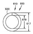
도 11a 내지 도 11b는 원래 공여자 뼈(782)보다 작은 외경 및 내경(717, 719)을 갖는 다른 바람직한 실시예에 따른 동종 이식 튜브(720)를 형성하기 위한 방법(700)을 도시한다. 동종 이식 튜브(720)는 뼈 고정구 임플란트(710)를 형성한다. 립(722, 724)은 바람직하게는 공여자 뼈(782)를 통해 형성된 슬롯의 대안 측면들 상에 형성된다. 복수의 구멍(728)을 갖고 일반적으로 탈미네랄화된 동종 이식 뼈의 직사각형 부분으로서 형성되는 슬래브(727)가 슬롯(726) 내에 수용되도록 구성된다. 복수의 다월 핀(775)은 도 11b에 도시된 바와 같이 정합 구멍(728, 721)을 통해 수용되도록 구성된다.11A-11B illustrate a method 700 for forming an
작동시에, 도 11a 및 도 11b를 계속 참조하면, 동종 이식 튜브(720)는 공여자 뼈(782)로부터 형성되고, 동종 이식 튜브의 외경 및 내경(717, 719)은 공여자 뼈(782)의 외경 및 내경(787, 789)보다 작다. 공여자 뼈(782)는 그 길이를 따라 절단되어 슬롯(726) 및 립(722, 724)을 형성한다. 구멍(721)은 립(722, 724) 내에 드릴링된다. 공여자 뼈(782)는 이어서 탈미네랄화된다. 립(722, 724) 및 선택적으로 구멍(721)은 이들의 강성을 유지하도록 탈미네랄화 프로세스 중에 마스킹된다. 탈미네랄화된 동종 이식 뼈의 다른 부분은 이어서 슬래브(727)를 생성하도록 직사각형 형태로 절단되고, 복수의 구멍(728)이 슬래브(727)를 통해 드릴링된다. 슬래브(727) 및 구멍(728)은 공여자 뼈(782) 상에 형성된 구멍(721) 및 립(722, 724)과 정합되도록 구성된다. 적절한 크기의 다월(dowel) 핀(775)이 뼈로부터 절단되고, 동종 이식 튜브(720)는 슬래브(727)를 립(722, 724)에 정합시키고 복수의 구멍(721)과 복수의 구멍(728)을 정렬함으로써 함께 조립된다. 복수의 핀(775)은 이어서 복수의 구멍(721, 727)을 통해 삽입된다. 일단 동종 이식 튜브(720)가 조립되면, 동종 이식 튜브(720)는 슬롯(726)과 슬래브(727) 사이, 뿐만 아니라 핀(775)과 구멍(721, 728) 사이에 형성된 연결부를 융합하도록 재차 탈미네랄화될 수 있다.In operation, continuing with reference to FIGS. 11A and 11B, the
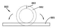
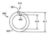
도 12a 내지 도 12f는 원래 공여자 뼈(882)보다 작은 외경 및 내경(817, 819)을 갖는 다른 바람직한 실시예에 따른 동종 이식 튜브(820)를 형성하기 위한 방법(800)을 도시한다. 튜브(820)는 뼈 스크류의 유지 강도 및 퍼처스를 바람직하게 증가시키기 위한 임플란트(810)를 생성한다. 정합 립(822, 824)은 바람직하게는 공여자 뼈(882)를 절단하고, 풀리게 하고, 다듬질함으로써 형성된 시트(885)의 대안 측면 상에 형성된다. 복수의 구멍(821)이 도 12c 내지 도 12d에 도시된 바와 같이 립(822, 824)을 통해 형성된다. 복수의 다월 핀(875)이 구멍(821)을 통해 수신되도록 구성된다. 핀(875)은 대문자 "I" 또는 "Z" 형상과 같은 복수의 직각을 포함하고, "Z" 형상의 코너부는 바람직하게는 경사각에 대조적으로 직각으로서 형성된다. 핀(875)이 뼈로부터 형성되고, 그 내부에 포함된 직각부는 가요성 지점으로 탈미네랄화되어 복수의 힌지(876, 877)가 직각부에 형성되게 되어, 핀(875)은 직선 구멍(821)을 통한 삽입 중에 직선형 구성으로 이들의 힌지(876, 877)에서 굴곡될 수 있고, 구멍(821)을 통해 삽입된 후에 이들의 원래의 "I" 또는 "Z" 형상으로 탄성 복귀된다.12A-12F illustrate a
작동시에, 도 12a 내지 도 12e를 계속 참조하면, 동종 이식 튜브(820)는 공여자 뼈(882)로부터 형성되고, 동종 이식 튜브(820)의 외경 및 내경(817, 819)은 공여자 뼈(882)의 외경 및 내경(887, 889)보다 작다. 공여자 뼈(882)는 탈미네랄화되고, 절단되고, 편평한 시트(885)로 풀려진다. 시트(885)는 소정의 치수로 다듬질되고, 정합 립(822, 824)이 절단되고, 구멍(821)이 립(822, 824)을 통해 드릴링되어 시트(886)를 형성한다. 시트(886)는 이어서 원통형 형태로 감기고, 립(822, 824)이 중첩되어 립(822, 824)의 양자 모두를 통한 구멍(821)이 정렬된다. 핀(875)이 중첩 구멍(821)을 통해 삽입될 때, 가요성 힌지(876, 877)가 일시적으로 직선화되고 구멍(821)에 대해 적절하게 위치될 때 이들의 초기 구성으로 탄성 복귀하는데, 즉 핀(756)의 더 긴 샤프트부(878)가 구멍(821)의 내부에서 횡단하고, 상부 및 저부 횡단부(881, 882)는 구멍(821)의 상부에서 돌출하고 횡단방향으로 놓인다. 추가적으로, 생체 적합성 접착제 및/또는 전자기 방사선 및/또는 추가의 탈미네랄화가 구멍(821) 내의 핀(875)의 고정을 더 향상시키도록 적용될 수 있다. 조립시에, 동종 이식 튜브(820)는 원래 공여자 뼈(882)를 특징화하는 외경 및 내경(887, 889)보다 작은 외경 및 내경(817, 819)을 갖는다.In operation, continuing with reference to FIGS. 12A-12E, the
도 13a 및 도 13b는 전술된 동종 이식 튜브(520, 620, 720 또는 820) 중 임의의 하나와 동일하거나 유사할 수 있거나, 대안적으로 방사선(590)의 인가로부터 생성되는 용접, 더브테일 조인트(659), 슬래브(727) 및 핀(775) 또는 구멍(821) 및 핀(875)과 같은 임의의 기계적 고정 메커니즘을 포함하지 않는 탈미네랄화되고, 분할 개방되고, 시트로 평탄화되고, 소정 치수로 절단되고, 관형 형태로 재감기는 공여자 뼈(982)로부터 생성될 수 있는 다른 바람직한 실시예에 따른 동종 이식 튜브(920)를 도시한다.13A and 13B may be the same as or similar to any one of the
대안적으로, 공여자 뼈(982)는 예를 들어 40 밀리미터(40 mm)의 소정의 폭, 예를 들어 약 0.5 밀리미터(0.5 mm) 내지 약 2 밀리미터(2 mm), 바람직하게는 약 0.75 밀리미터(0.75 mm)의 소정의 두께의 비교적 편평한 시트로 형성될 수 있다. 시트는 시트로서 외과의사에게 공급될 수 있고, 탈미네랄화 및/또는 동결 건조될 수 있고, 외과의사는 임플란트의 직경 및 구멍의 직경에 따라 수술 중에 또는 수술 직전에 소정의 폭으로 시트를 절단할 수 있다. 외과의사는 시트를 관형 형태로 감아서 구멍 내에 이를 삽입할 수 있다. 스크류는 그 후에 시트 재료를 감긴 또는 스트립 형태로 하여 뼈 내의 구멍 내에 삽입될 수 있어 바람직하게는 스크류의 퍼처스 및 유지 강도를 증가시킨다.Alternatively, donor bone 982 may have a predetermined width of, for example, 40 millimeters (40 mm), for example from about 0.5 millimeters (0.5 mm) to about 2 millimeters (2 mm), preferably about 0.75 millimeters ( 0.75 mm) to a relatively flat sheet of a predetermined thickness. The sheet may be supplied to the surgeon as a sheet, demineralized and / or lyophilized, and the surgeon may cut the sheet to a predetermined width during or immediately before surgery, depending on the diameter of the implant and the diameter of the hole. have. The surgeon can wind the sheet in a tubular form and insert it into the hole. The screw can then be inserted into a hole in the bone in the form of a wound or stripped sheet material, preferably increasing the aperture and retention strength of the screw.
바람직한 방법은 금속 또는 플라스틱으로 형성될 수 있고 동종 이식 튜브(920)가 그 내부에 삽입되는 튜브(955)를 추가로 포함한다. 작동시에, 도 13a를 참조하면, 동종 이식 튜브(920)는 전술된 바와 같이 형성되고 튜브(955) 내에 삽입될 수 있다. 동종 이식 튜브(920)는 튜브(955) 내부에 있는 동안 동결 건조될 수 있고, 또는 동결 건조되어 튜브(955) 내에 삽입될 수 있다. 동결 건조된 동종 이식 튜브(920)는 바람직하게는 포장 및 선적 중에 튜브(955) 내부에 잔류한다. 대안적으로, 임플란트(920)는 수술에 앞서 또는 수술 중에 튜브(955) 내에 삽입될 수 있다. 튜브(955)는 이어서 플런저(950) 및 추골체(5)의 척추경(4) 내의 미리 형성된 파일럿 구멍과 정렬되고, 또는 푸시 로드가 튜브(955)에 대해 전진되어 동종 이식 튜브(920)를 척추경 내로 압박하여 증강 또는 가드 디바이스로서 기능하게 되고, 또는 대안 실시예에서 추골체(5)의 내부로 압박하여 추골체 증강 충전재로서 기능하게 된다. 척추경(4) 내로의 동종 이식 튜브(920)의 도입시에, 동종 이식 튜브(920)는 혈액 및 다른 생체 물질과 접촉하게 될 때 원 위치 재수화를 경험하게 되어, 이에 의해 척추경을 통해 형성된 구멍 내에 확실히 끼워지도록 팽창된다. 대안적으로, 튜브(955)는 스크류를 수용하게 되는 구멍 내에 삽입될 수 있다. 푸시 로드(950)가 튜브 내에 배치되고, 임플란트의 근위 단부에 접촉할 수 있다. 튜브(955)는 그 후에 푸시 로드(950) 상으로 후퇴되어 임플란트(920)가 구멍 내의 제 위치에 잔류된다. 임플란트는 이어서 혈액 및 생체 물질과의 접촉시에 재수화될 수 있다. 이 대안적인 방법은 삽입 절차 중에 임플란트를 더 양호하게 보호할 수 있고, 특히 더 취약성, 가요성 또는 이완성 임플란트를 보호하여 이들이 적절하게 위치되고 손상되지 않고 유지되게 한다.The preferred method further includes a
도 14a 및 도 14b는 원통형 동종 이식 튜브(920)와는 대조적으로, 나선형 관형 구조체를 형성하기 위해 나선형으로 감겨지는 것을 제외하고는, 동종 이식 튜브(920)와 유사한 방식으로 형성된 다른 바람직한 실시예에 따른 동종 이식 튜브(1020)를 도시한다. 동종 이식 튜브(1020)는 동결 건조시에, 바람직하게는 재수화시의 그 외경보다 작고 이식되도록 의도되는 척추경 구멍의 직경보다 작은 외경에 의해 특징화된다. 이와 같이, 동종 이식 튜브(1020)는 척추경(4) 내에 형성된 다양한 구멍 크기에 적합하도록 구성되고, 이용 가능한 공여자 조직(1082)으로부터 형성된 임플란트의 수율이 향상된다. 동결 건조된 동종 이식 튜브(1020)의 사용은 그 감소된 사전 재수화 직경에 기인하여 척추경의 벽 내의 임의의 불규칙부와 접촉하는 것을 회피함으로써 척추경 구멍 내로의 삽입 중에 경험되는 간섭을 더 회피한다.14A and 14B are in accordance with another preferred embodiment formed in a manner similar to
작동시에, 도 14a 및 도 14b를 계속 참조하면, 동종 이식 튜브는 나선형으로 권취되어 동결 건조된다. 동종 이식 튜브(1020)는 이어서 척추경(4) 내에 형성된 구멍 내로 수동으로 삽입되고, 혈액 또는 척추경(4)의 내부에 고유한 다른 생체 물질과 접촉시에 재수화되고 팽창되어, 바람직하게는 후속의 척추경 스크류(7) 삽입을 위해 전술된 바와 같이 척추경 증강 디바이스 또는 가드를 제공하기 위해 구멍 내에 적당하게 끼워진다. 나선형으로 권취된 임플란트(1020)는 도 13에 대해 전술된 방법 및 기구를 사용하여, 또는 도 8에 설명된 삽입기 기구를 사용하여 삽입될 수 있다.In operation, with continued reference to FIGS. 14A and 14B, the allograft tube is spiral wound and lyophilized.
도 15를 참조하면, 동종 이식 튜브(1020)의 삽입을 위해 유용한 바람직한 삽입기(1091)가 제공된다. 삽입기(1091)는 또한 도 1 내지 도 12의 임플란트를 삽입하는데 사용될 수 있다. 삽입기(1091)는 그 원위 단부(1094)에 확산 원추(1093)를 갖는 내부 샤프트(1092)를 포함한다. 내부 샤프트(1092)는 내부 샤프트(1092)로부터 외부 슬리브(1095)를 통해 횡단방향으로 연장하는 하나 이상의 핀(1096)을 거쳐 캐뉼레이션된 외부 슬리브(1095)에 결합된다. 하나 이상의 핀(1096)이 내부 샤프트(1092) 및 외부 슬리브(1095)에 용접되고, 스크류 결합되거나, 다른 방식으로 고정 결합될 수 있다. 외부 슬리브(1095)는 그 원위 단부(972)에 개구(1097)를 추가로 포함한다. 삽입기(1091)는 내부 샤프트(1092)와 정합하도록 구성된 중공 원위부(1100)를 포함하는 플런저(1099)를 추가로 포함한다. 플런저(1099)는 내부 샤프트(1092) 및 외부 슬리브(1095)에 대해 삽입기(1091)의 종축을 따라 축방향으로 이동한다. 플런저(1099)는 하나 이상의 핀(1096)을 통해 거기에 활주 가능하게 수용되도록 구성된 하나 이상의 슬롯(1068)을 포함한다. 플런저(1099)를 통해 배치된 슬롯(1068)의 수는 바람직하게는 삽입기(1091) 내에 포함된 핀(1096)의 수에 대응한다. 하나 이상의 핀(1096)이 내부 샤프트(1092)에 대해 플런저(1099)의 과잉 연장을 방지하고, 그 결과 척추경 구멍 내로의 동종 이식 튜브(920)의 과잉 삽입을 방지할 뿐만 아니라, 외부 슬리브(1095)의 원위 단부(1098)와 정렬되어 확산기 코어(1093)의 원위 단부를 유지하도록 구성된다.Referring to FIG. 15, there is provided a
작동시에, 도 14a 내지 도 15b를 계속 참조하면, 나선형으로 권취된 동결 건조된 동종 이식 튜브(920, 1020)는 내부 샤프트(1092) 주위에 동심으로 삽입기(1091) 내로 로딩되어 그 내부에 저장된다. 본 명세서에 설명된 임의의 다른 임플란트 뿐만 아니라 다른 임플란트는 대안적으로 및 추가적으로 삽입기(1091)를 사용하여 로딩되고 삽입될 수 있다. 수술에 앞서, 동종 이식 튜브(920, 1020)는 염수와 같은 재수화제를 사용하여 삽입기(1091) 내부에 있는 동안 재수화될 수 있다. 삽입기(1091)의 원위 단부는 추골체(5)에 인접하여 배치되어(도 15a에 도시된 바와 같이), 외부 슬리브(1095)의 원위 단부(1098) 내의 개구(1097)가 척추경(4)을 통해 형성된 구멍(2)과 정렬되게 된다. 플런저(1099)는 외부 슬리브(1095) 및 내부 샤프트(1092)에 대해 전진되고, 대응 하나 이상의 슬롯(1068)과 하나 이상의 핀(1096)의 상호 작용을 통해 안내된다. 플런저(1099)가 전진될 때, 플런저(1099)의 원위 단부는 동종 이식 튜브(920)의 근위 단부(933)에 결합되고 동종 이식 튜브(920)가 삽입기(1091)의 원위 단부 내에서 그로부터 전진되게 한다. 동종 이식 튜브(920)가 내부 샤프트(1092)를 따라 원위측으로 전진될 때, 동종 이식 튜브(920)는 확산기 원추(1093) 상에서 전진하여, 척추경(4) 내에 형성된 구멍 내로의 이식 직전에 동종 이식 튜브(920)가 반경방향으로 팽창되게 한다(예를 들어, 풀림). 사용된 임플란트에 따라, 확산기 원추(1093)는 임플란트를 팽창시키거나 팽창시키지 않을 수 있다. 하나 이상의 핀(1096)이 동종 이식 튜브(920)의 과잉 삽입을 방지하기 위해 척추경 구멍에 대해 동종 이식 튜브(920)의 최적의 전진시에 하나 이상의 슬롯(1068)의 말단부에 결합한다.In operation, with continued reference to FIGS. 14A-15B, the spirally wound freeze dried
대안적으로, 삽입기(1091)는 상이한 방법으로 이용될 수 있다. 대안적인 방법에서, 임플란트는 삽입기 내에 그리고 내부 샤프트(1092) 주위에 로딩되고, 삽입기(1091)의 원위 단부는 뼈 증강 디바이스가 삽입되는 뼈 내에 준비된 구멍 내에 삽입된다. 플런저(1099)는 외부 슬리브(1095)에 대해 전진되어 임플란트의 근위 단부에 결합되게 된다. 플런저(1099)는 삽입기(1091)가 뼈로부터 후퇴될 때 임플란트가 뼈 및 구멍 내에 잔류하는 동안 뼈로부터 외부 슬리브(1095) 및 확산기 원추(1093)를 수축하도록 외부 슬리브(1095)에 대해 이동된다. 외부 슬리브(1095) 및 확산기 원추(1093)가 뼈로부터 후퇴될 때, 임플란트는 바람직하게는 임플란트를 더 큰 크기로 확장시키고, 펴지게 하고, 그리고/또는 풀리게 하는 확산기 원추(1093) 상을 통과할 수 있다. 따라서, 콤팩트한 뼈 증강 디바이스를 갖는 비교적 작은 직경의 기구(1091)가 비교적 작은 구멍 내에 삽입되어 뼈 스크류를 수용할 수 있고, 삽입기(1091)는 외부 슬리브(1095)를 후방 견인하도록 작동되고, 뼈 증강 디바이스는 그 삽입된 크기보다 큰 크기로 뼈 내에서 팽창되어 전개된다.Alternatively,
도 16을 참조하면, 동종 이식 조직 형 및 뼈 스크류를 포함하는 스크류 증강 시스템의 바람직한 실시예가 도시된다. 척추경(4)을 통해 추골체(5) 내로 삽입되는 척추경 스크류(7)는 바람직하게는 수술 중에 방사선 그래픽 시각화될 수 있는 척추경 스크류의 샤프트의 짧은 축을 통해 하나 이상의 반경방향 구멍(8)을 포함한다. 이들 반경방향 구멍(8)은 적절한 배향으로 위치될 때, 척추경(4) 내에 형성된 교차 구멍과 척추경 스크류(7)의 반경방향 구멍(8)이 정렬되도록 척추경 스크류의 삽입에 이어서 척추경(4)을 통해 교차 구멍을 드릴링하기 위한 가이드로서 기능할 수 있다.Referring to FIG. 16, a preferred embodiment of a screw enhancement system comprising an allograft tissue type and a bone screw is shown. The
동종 이식 뼈의 스트립(29)은 바람직하게는 가요성의 짧고 강한 부분적으로 탈미네랄화된 중간부인 2개의 탈미네랄화된 대향 단부들을 바람직하게 포함하는 척추경 스크류(7)의 반경방향 구멍(8)과 함께 사용된다. 동종 이식 스트립(29)은 바람직하게는 척추경(4)의 교차 구멍 및 척추경 스크류의 반경방향 구멍(8)을 통해 삽입되어, 동종 이식 스트립(29)의 더 강한 중간부가 척추경 스크류의 반경방향 구멍(8) 내의 핀으로서 위치되게 된다. 매듭이 동종 이식 스트립(29)의 가요성 대향 단부들을 사용하여 추골의 후방 요소 주위에 속박되고, 따라서 추골(3)에 대해 척추경 스크류를 고정한다.The
동종 이식 스트립(29)의 전체 길이는 완전히 탈미네랄화될 수 있고, 생체 적합성 재료로 형성된 아일릿형 디바이스(미도시)가 동종 이식 스트립(29)의 중간부 주위에 고정될 수 있어 척추경 스크류(7)의 반경방향 구멍(8)에 접촉하는 동종 이식 스트립(29)의 부분을 보호하고 구조적 강도를 제공하기 위해 동종 이식 스트립(29)과 척추경 스크류의 반경방향 구멍(8) 사이의 배리어 또는 그로멧(grommet)으로서 기능한다. 구멍은 대안적으로 인접 신경 요소 또는 혈관에 손상을 주지 않도록 적절한 각도 및 적절한 주의로 판으로 형성될 수 있고, 동종 이식 스트립(29)은 척추경 스크류(7)의 반경방향 구멍(8)을 통해 그리고 판 내에 형성된 구멍을 통해 또는 구멍 내로 스크류 쓰레드 형성될 수 있다. 봉합 스크류 쓰레드 또는 금속 와이어, 예를 들어 티타늄 와이어 등이 또한 탈미네랄화된 동종 이식 스트립(29) 대신에 사용될 수 있다.The overall length of the
도 17을 참조하면, 척추경 스크류(7)의 근위 단부로부터 연장하여 척추경 스크류의 종축을 따라 중간점에 또는 그 부근에 위치된 하나 이상의 반경방향 절결부 또는 슬롯(11)에서 종료하는 캐뉼레이션된 부분(9)을 바람직하게 포함하는 척추경 스크류(7)가 개시된다. 슬롯(11)은 척추경 스크류의 외부로부터 내부 캐뉼레이션으로 연장된다. 하나 이상의 부분적으로 또는 완전히 탈미네랄화된 뼈 스트립(56)이 예를 들어 플런저 로드(50)와 같은 간단한 기구를 사용하여 근위 단부(6)로부터 캐뉼레이션(9) 아래로 반경방향 절결부(11)로부터 부분적으로 공급될 수 있다.Referring to FIG. 17, a cannulation extending from the proximal end of the
도 17의 실시예에서, 척추경 스크류(7)가 추골(3) 내로 전진되고 슬롯(11)이 척추경(4)의 내부와 접촉하게 될 때, 돌출 동종 이식 스트립(56)은 척추경(4)의 내부에 대해 분쇄된다. 척추경 스크류(7)가 더 전진할 때, 동종 이식 뼈 스트립(56)은 캐뉼레이션된 내부(9)로부터 반경방향 슬롯(11)으로부터 견인되고, 척추경 스크류(7)가 완전히 안착되어 분쇄된 동종 이식 뼈가 척추경 스크류의 스크류 쓰레드 형성된 근위측 외부를 둘러싸고 추가의 퍼처스가 제공될 때까지 척추경(4)의 내부에 대해 분쇄된다. 하나 이상의 반경방향 슬롯(11)이 척추경 스크류(7)의 원위 단부 또는 그 부근에 배치될 수 있고, 캐뉼레이션된 내부 부분(9)이 근위 단부(6)로부터 연장되고 반경방향 슬롯(11)에서 종료될 수 있다. 반경방향 슬롯은 척추경 스크류의 샤프트를 따라 다른 위치에 제공될 수 있다. 동종 이식 뼈 스트립(56)은 캐뉼레이션(9)으로 하향 공급되고 부분적으로 원위측 반경방향 절결부(11)를 나올 수 있다. 척추경 스크류(7)가 뼈 내로 전진할 때, 동종 이식 스트립(56)은 원위측 반경방향 슬롯(11)으로부터 견인되어 분쇄된 동종 이식 뼈가 원위 단부로부터 근위 단부로 스크류 쓰레드 형성 샤프트를 둘러싸게 된다. 유동성 재료는 스크류(7)를 척추경 내로 구동하는 커플링 메커니즘에 의해 스크류(7)의 스크류 쓰레드 내로 주입될 수 있다.In the embodiment of FIG. 17, when the
도 18을 참조하면, 캐뉼레이션된 척추경 스크류(7)는 바람직하게는 캐뉼레이션의 단부에 및/또는 척추경 스크류(7)의 중간점과 원위 단부 사이에 배치된 하나 이상의 반경방향 슬롯(11)을 포함한다. 작동시에, 척추경 스크류(7)는 바람직하게는 척추경(4)을 통해 추골체(5) 내로 완전히 삽입되고, 하나 이상의 부분적으로 탈미네랄화된 동종 이식 스트립(56)이 척추경 스크류의 캐뉼레이션된 내부 내로 배치된다. 푸셔 로드(50) 또는 다른 기구가 바람직하게는 척추경 스크류(7)의 근위 단부(6)에 배치되고, 동종 이식 스트립(56)의 근위 단부에 지지되게 되어 동종 이식 뼈 스트립(56)의 원위 단부가 바람직하게는 스크류(7)의 종축에 대해 소정 각도로 반경방향 절결부(11)로부터 전진하여, 추골체(3)의 해면성 내부 내로 스크류(7)를 위한 고정을 제공한다. 다음에, 척추경 스크류(7)의 근위 단부는 바람직하게는 하나 이상의 동종 이식 스트립(56)이 척추경 스크류(7)로부터 되돌아오는 것을 방지하기 위해 예를 들어, 뼈, 스테인레스강 또는 티타늄과 같은 생체 적합성 재료로 형성된 플러그로 밀봉된다.Referring to FIG. 18, the cannulated
도 19a 내지 도 19c를 참조하면, 다른 실시예에 따른 척추경 스크류(1207)는 근위부(1205), 원위부(1206) 및 근위부(1205)를 통해 원위부(1206) 내로 적어도 부분적으로 연장하는 캐뉼레이션된 내부(1209)를 포함한다. 힌지 메커니즘(1211)은 바람직하게는 종축을 따라 중간점에서 또는 중간점 부근에서 원위부(1206) 및 근위부(1205)에 연결된다. 원위부(1206)는 바람직하게는 종축을 따라 캐뉼레이션된 내부(1209) 내로 슬롯(1242)을 포함하여, 복수의, 예를 들어 4개의 레그(1216)가 형성되어 가요성 힌지 메커니즘(1211)을 사용하여 서로 연결되게 된다. 스크류 쓰레드가 바람직하게는 스크류(1207)의 샤프트의 외부면 상에 가공된다. 제 1 상태에서, 도 19c에 도시된 바와 같이, 4개의 레그가 폐쇄 위치를 차지하여 원위부(1206)가 표준 척추경 스크류 샤프트와 유사하게 된다. 작동시에, 도 19a에 도시된 바와 같이, 압축 코일 스프링(1201)이 바람직하게는 기다란 중공 튜브(1202) 내로 압력 하에서 삽입된다. 코일 스프링(1201)은 압축되고 튜브(1202)가 스프링(1201)을 그 압축 상태로 유지하지 않으면 팽창할 것이다. 튜브(1202)는 바람직하게는 척추경 스크류(1207)의 캐뉼레이션된 내부(1209) 내로 삽입되어 스프링(1201)이 척추경 스크류(1207)의 원위 단부(1206) 또는 그 부근에 위치되게 된다.19A-19C,
다음, 척수경 스크류(1207)는 바람직하게는 척추경(4)을 통해 추골(3) 내에 삽입된다. 푸시 로드(1203)가 도 19c에 도시된 바와 같이 바람직하게는 튜브(1202)가 스크류(1207)로부터 후퇴될 때 스크류(1207)의 원위부(1206) 내의 위치에 스프링(1201)을 유지하기 위해 스프링(1201)의 근위 단부에 대해 배치된다. 튜브(1202)가 스프링(1201)으로부터 수축될 때, 도 19d에 도시된 바와 같이, 튜브(1202) 내에 압축 상태로 유지되는 스프링(1201)은 더 이상 튜브(1202) 내에 수납되지 않고, 따라서 스프링(1201)이 풀리고 레그(1216)를 압박 개방하여 원위부(1206)가 바람직하게는 추골(3)의 해면성 내부 내로 팽창되게 되고 척추경 스크류(1207)의 견인 강도가 증가된다. 척수경 스크류(1207)는 도 19d에 도시된 바와 같이 2개의 힌지 메커니즘(1211, 1212)을 갖고 도시되어 있지만, 다른 힌지 메커니즘 및 구성이 고려된다. 게다가, 뼈 증강 스크류(1207)는 4개의 레그(1216)를 갖는 것으로서 도시되어 있지만, 더 많거나 적은 레그(1216)가 이용될 수 있다.
광범위한 발명적인 개념으로부터 벗어나지 않고 전술된 실시예에 변경이 이루어질 수 있다는 것이 당 기술 분야의 숙련자들에 의해 이해될 수 있을 것이다. 따라서, 본 발명은 개시된 특정 실시예에 한정되는 것은 아니고, 첨부된 청구범위에 의해 규정된 바와 같은 본 발명의 사상 및 범주 내의 수정을 커버하는 것으로 의도된다는 것이 이해된다.
It will be understood by those skilled in the art that changes may be made in the above-described embodiments without departing from the broad inventive concept. Accordingly, it is to be understood that the invention is not limited to the specific embodiments disclosed and is intended to cover modifications within the spirit and scope of the invention as defined by the appended claims.
Claims (39)
Translated fromKorean미리 형성된 구멍 내로 삽입을 위해 치수 설정 및 구성되는 길이 방향의 세장형 동종 이식 조직 부재로서, 상기 부재는 원위 단부, 근위 단부, 종축 및 상기 근위 단부의 근위 개구로부터 상기 원위 단부를 향해 연장하는 중공 캐비티를 갖고, 상기 부재는 링 섹션으로서 상기 근위 단부에 형성된 연속 벽, 중공 내부와 연통하는 상기 근위 개구를 갖는 근위부 및 원위부를 추가로 갖는, 상기 길이 방향의 세장형 동종 이식 조직 부재를 포함하고,
상기 동종 이식 조직 슬리브의 적어도 일부는 적어도 부분적으로 탈미네랄화되는 임플란트.An implant for positioning between the screw shaft and surrounding bone tissue to increase the retention strength of the screw,
A longitudinal elongated allograft tissue member dimensioned and configured for insertion into a preformed hole, the member extending from the distal end, the proximal end, the longitudinal axis and the proximal opening of the proximal end toward the distal end. Wherein said member comprises said longitudinal elongated allogeneic tissue member further having a continuous wall formed at said proximal end as a ring section, a proximal portion with said proximal opening in communication with a hollow interior, and a distal portion,
At least a portion of the allograft tissue sleeve is at least partially demineralized.
원위 단부, 근위 단부 및 이들 사이로 연장하는 종축을 갖는 뼈 내의 미리 형성된 구멍 내로 삽입을 위해 치수 설정 및 구성되는 세장형 동종 이식 조직 형(form)으로서, 상기 동종 이식 조직 형은 동종 이식 조직 근위부 및 동종 이식 조직 원위부를 추가로 포함하는, 상기 세장형 동종 이식 조직 형을 포함하고,
상기 근위부는 상기 근위 단부에 있는 근위 개구, 중공 내부를 형성하는 캐비티, 및 상기 중공 내부를 둘러싸는 벽을 포함하고,
상기 원위부는 중실형이고, 상기 원위부의 적어도 일부는 적어도 하나의 슬릿을 포함하고,
상기 근위부 및 상기 원위부 중 적어도 하나는 부분적으로 탈미네랄화되고, 상기 근위부 및 상기 원위부는 가요성 연결되는 임플란트.An implant for positioning between the screw shaft and surrounding bone tissue to increase the retention strength of the screw,
An elongated allogeneic tissue form dimensioned and configured for insertion into a preformed hole in a bone having a distal end, proximal end, and a longitudinal axis extending therebetween, the allograft tissue type being proximal and allogeneic. Comprising said elongate allograft tissue type, further comprising a distal transplant tissue,
The proximal portion comprises a proximal opening at the proximal end, a cavity defining a hollow interior, and a wall surrounding the hollow interior,
The distal portion is solid, at least a portion of the distal portion comprises at least one slit,
At least one of the proximal and distal portions is partially demineralized and the proximal and distal portions are flexiblely connected.
커넥터 스트립 및 상기 커넥터 스트립으로부터 연장하는 복수의 말단부들을 갖는 제 1 동종 이식 조직편으로서, 상기 커넥터 스트립은 상기 말단부들을 연결하는 연속 링을 형성하고, 복수의 간극들이 상기 말단부들을 분리하는, 상기 제 1 동종 이식 조직편; 및
결합 부재 및 상기 결합 부재로부터 연장하는 복수의 핑거 부재들을 갖는 제 2 동종 이식 조직편으로서, 상기 결합 부재는 상기 핑거들을 연결하는 연속 링을 형성하고, 복수의 공간들이 상기 핑거들을 분리하고, 상기 제 1 동종 이식 조직편은 상기 제 2 동종 이식 조직편에 부착되어, 상기 커넥터 스트립이 상기 결합 부재의 원위측에 있게 하고 상기 말단부들이 상기 결합 부재의 근위측으로 연장되게 하며, 또한 상기 핑거들이 상기 커넥터 스트립의 원위측으로 연장되게 하는, 상기 제 2 동종 이식 조직편을 포함하는 동종 이식 뼈 고정구.An allograft bone fixture positioned within the bone and for receiving a bone screw,
A first allogeneic tissue piece having a connector strip and a plurality of distal ends extending from the connector strip, wherein the connector strip forms a continuous ring connecting the distal ends, the plurality of gaps separating the distal ends; Graft tissue fragments; And
A second allograft tissue piece having an engagement member and a plurality of finger members extending from the engagement member, wherein the engagement member forms a continuous ring connecting the fingers, the plurality of spaces separating the fingers, and the first An allograft is attached to the second allograft so that the connector strip is distal to the connecting member and the distal ends extend proximal to the connecting member, and the fingers are distal to the connector strip. An allograft bone fixture comprising the second allograft tissue piece to be extended.
골수내 관을 갖는 한 조각의 공여자 뼈(donor bone)를 획득하는 단계로서, 상기 공여자 뼈는 내경 및 외경에 의해 특징화되는, 상기 한 조각의 공여자 뼈를 획득하는 단계;
상기 공여자 뼈를 탈미네랄화하는 단계;
상기 탈미네랄화된 공여자 뼈의 표면을 통해 절결부를 형성하는 단계;
시트를 형성하기 위해 상기 탈미네랄화된 공여자 뼈를 풀리게 하는 단계;
상기 시트를 원하는 세트의 치수들로 다듬질하는 단계; 및
상기 공여자 뼈의 내경보다 작은 내경 및 상기 공여자 뼈의 외경보다 작은 외경에 의해 특징화되는 관형 임플란트를 형성하기 위해 상기 시트를 감기게 하는 단계를 포함하는 관형 동종 이식 임플란트 제조 방법.A method of making a tubular allograft implant configured for insertion into a preformed hole in a bone, the method comprising:
Obtaining a piece of donor bone having an intramedullary canal, wherein the donor bone is characterized by an inner diameter and an outer diameter;
Demineralizing the donor bone;
Forming a cut through the surface of the demineralized donor bone;
Unwinding the demineralized donor bone to form a sheet;
Finishing the sheet to a desired set of dimensions; And
Winding the sheet to form a tubular implant characterized by an inner diameter smaller than the inner diameter of the donor bone and an outer diameter smaller than the outer diameter of the donor bone.
(a) 추골의 상기 척추경 내에 구멍을 준비하는 단계;
(b) 뼈 내에 삽입을 위한 스크류를 제공하는 단계;
(c) 상기 추골 내에 형성된 상기 구멍의 원주와 대략 동일하거나 또는 그보다 작은 외주 원주를 갖는 뼈 증강 디바이스를 선택하는 단계로서, 상기 뼈 증강 디바이스는 근위 단부, 원위 단부, 및 상기 근위 단부에 형성된 근위 개구로부터 상기 원위 단부를 향해 연장하는 중공 캐비티를 갖는 길이 방향의 세장형 동종 이식 조직 형을 포함하고, 상기 근위 단부 내의 개구는 상기 스크류의 직경과 대략 동일하거나 또는 그보다 작고, 상기 조직 형은 링 섹션을 형성하는 상기 근위 단부에 연속 벽을 추가로 갖는, 상기 뼈 증강 디바이스를 선택하는 단계;
(d) 상기 근위 단부가 상기 척추경 내의 구멍의 개구와 실질적으로 동일 높이가 되고 상기 임플란트가 상기 추골 내로 연장하도록, 상기 추골 내에 상기 뼈 증강 디바이스를 삽입하는 단계; 및
(e) 상기 스크류를 상기 뼈 증강 디바이스의 보어 내로 삽입하는 단계를 포함하는 방법.A method for inserting a screw in a pedicle,
(a) preparing a hole in the pedicle of the vertebrae;
(b) providing a screw for insertion into the bone;
(c) selecting a bone enhancement device having an outer circumference approximately equal to or less than the circumference of the hole formed in the vertebra, the bone enhancement device having a proximal end, a distal end, and a proximal opening formed at the proximal end A longitudinal elongated allograft tissue type having a hollow cavity extending from the distal end toward the distal end, wherein the opening in the proximal end is approximately equal to or less than the diameter of the screw and the tissue type defines a ring section. Selecting the bone reinforcement device further having a continuous wall at the proximal end to form;
(d) inserting the bone reinforcement device into the vertebra so that the proximal end is substantially flush with the opening of the hole in the pedicle and the implant extends into the vertebrae; And
(e) inserting the screw into the bore of the bone enhancement device.
Applications Claiming Priority (4)
| Application Number | Priority Date | Filing Date | Title |
|---|---|---|---|
| US7399808P | 2008-06-19 | 2008-06-19 | |
| US61/073,998 | 2008-06-19 | ||
| US10686208P | 2008-10-20 | 2008-10-20 | |
| US61/106,862 | 2008-10-20 |
Publications (1)
| Publication Number | Publication Date |
|---|---|
| KR20110033199Atrue KR20110033199A (en) | 2011-03-30 |
Family
ID=40974386
Family Applications (1)
| Application Number | Title | Priority Date | Filing Date |
|---|---|---|---|
| KR1020117000962AWithdrawnKR20110033199A (en) | 2008-06-19 | 2009-06-19 | Bone Screw Percussion Augmented Implants, Systems and Technologies |
Country Status (8)
| Country | Link |
|---|---|
| US (1) | US8840677B2 (en) |
| EP (1) | EP2355721A2 (en) |
| JP (1) | JP2011525229A (en) |
| KR (1) | KR20110033199A (en) |
| CN (1) | CN102119007A (en) |
| BR (1) | BRPI0914950A2 (en) |
| CA (1) | CA2728312A1 (en) |
| WO (1) | WO2009155577A2 (en) |
Cited By (2)
| Publication number | Priority date | Publication date | Assignee | Title |
|---|---|---|---|---|
| KR20140133532A (en)* | 2012-01-31 | 2014-11-19 | 더유니버시티오브톨레도 | Bioactive fusion device |
| WO2019226388A1 (en)* | 2018-05-21 | 2019-11-28 | Warsaw Orthopedic, Inc. | Spinal implant system and methods of use |
Families Citing this family (69)
| Publication number | Priority date | Publication date | Assignee | Title |
|---|---|---|---|---|
| WO2009155121A2 (en) | 2008-05-30 | 2009-12-23 | Amgen Inc. | Inhibitors of pi3 kinase |
| KR20110033199A (en)* | 2008-06-19 | 2011-03-30 | 신세스 게엠바하 | Bone Screw Percussion Augmented Implants, Systems and Technologies |
| US9364276B2 (en) | 2009-07-09 | 2016-06-14 | Smith & Nephew, Inc | Tissue graft anchor assembly and instrumentation for use therewith |
| CN101912300B (en)* | 2009-09-29 | 2012-08-22 | 张强 | Minimally invasive pedicle screw fixation for thoracolumbar fractures |
| US20110288588A1 (en)* | 2010-05-20 | 2011-11-24 | Spinefrontier Inc | System and method for facet fixation and fusion |
| US9724140B2 (en) | 2010-06-02 | 2017-08-08 | Wright Medical Technology, Inc. | Tapered, cylindrical cruciform hammer toe implant and method |
| US8608785B2 (en) | 2010-06-02 | 2013-12-17 | Wright Medical Technology, Inc. | Hammer toe implant with expansion portion for retrograde approach |
| US9498273B2 (en) | 2010-06-02 | 2016-11-22 | Wright Medical Technology, Inc. | Orthopedic implant kit |
| CN103006312B (en)* | 2010-09-03 | 2017-11-03 | 张强 | Minimally invasive bone fracture screw inserts opener |
| DE102010041226A1 (en) | 2010-09-22 | 2012-03-22 | Aces Gmbh | Bone anchoring device |
| CA2826941C (en)* | 2011-02-14 | 2019-09-10 | Glenn R. Buttermann | Orthopaedic device |
| US9687278B2 (en)* | 2011-03-21 | 2017-06-27 | Ronald Childs | Sleeve for bone fixation device |
| US9113972B2 (en) | 2011-08-24 | 2015-08-25 | Pioneer Surgical Technology, Inc. | Apparatus and methods for immobilization and fusion of a synovial joint |
| HK1201138A1 (en)* | 2011-10-10 | 2015-08-28 | William Casey Fox | Shape changing bone implant for enhanced healing |
| US9554914B2 (en)* | 2011-12-12 | 2017-01-31 | Wright Medical Technology, Inc. | Fusion implant |
| ITMI20112361A1 (en)* | 2011-12-22 | 2013-06-23 | Franco Beoni | SURGICAL SCREWS WITH BONE SHIRT |
| CN104271057A (en)* | 2012-03-12 | 2015-01-07 | 维克辛姆公司 | Universal anchor for bone fixation |
| US9283089B2 (en) | 2012-04-05 | 2016-03-15 | Warsaw Orthopedic, Inc. | Interbody bone implant device |
| US9730801B2 (en) | 2012-04-17 | 2017-08-15 | Warsaw Orthopedic, Inc. | Interbody bone implant device |
| US9101606B2 (en) | 2012-04-19 | 2015-08-11 | Warsaw Orthopedic, Inc. | Bone delivery system having a therapeutic agent |
| US9220608B2 (en) | 2012-04-24 | 2015-12-29 | Warsaw Orthopedic, Inc. | Facet joint implant device |
| US8771368B2 (en) | 2012-04-24 | 2014-07-08 | William F. McKay | Interspinous bone implant device |
| US9480567B2 (en) | 2012-05-07 | 2016-11-01 | Warsaw Orthopedic, Inc. | Bone implants and methods comprising demineralized bone material |
| US9585764B2 (en) | 2012-07-26 | 2017-03-07 | Warsaw Orthopedic, Inc. | Bone implant device |
| US20140067069A1 (en) | 2012-08-30 | 2014-03-06 | Interventional Spine, Inc. | Artificial disc |
| US8915947B2 (en)* | 2012-10-18 | 2014-12-23 | Spectrum Spine Ip Holdings, Llc | Surgical access system |
| US10172651B2 (en) | 2012-10-25 | 2019-01-08 | Warsaw Orthopedic, Inc. | Cortical bone implant |
| US20140180428A1 (en)* | 2012-12-21 | 2014-06-26 | Wright Medical Technology, Inc. | Percutaneous expanding hammertoe implant |
| US8945232B2 (en) | 2012-12-31 | 2015-02-03 | Wright Medical Technology, Inc. | Ball and socket implants for correction of hammer toes and claw toes |
| US9265609B2 (en) | 2013-01-08 | 2016-02-23 | Warsaw Orthopedic, Inc. | Osteograft implant |
| US9201049B2 (en)* | 2013-03-13 | 2015-12-01 | Idex Health & Science Llc | Connector with structural reinforcement and biocompatible fluid passageway |
| US9585695B2 (en) | 2013-03-15 | 2017-03-07 | Woven Orthopedic Technologies, Llc | Surgical screw hole liner devices and related methods |
| CN105916458B (en)* | 2013-06-24 | 2019-09-27 | 托莱多大学 | Bioactive Fusion Devices |
| DE102013107881A1 (en) | 2013-07-23 | 2015-01-29 | Aesculap Ag | System for anchoring a pedicle screw, associated kit, spacer and Pedikelaugmentat |
| US9724139B2 (en) | 2013-10-01 | 2017-08-08 | Wright Medical Technology, Inc. | Hammer toe implant and method |
| US9474561B2 (en) | 2013-11-19 | 2016-10-25 | Wright Medical Technology, Inc. | Two-wire technique for installing hammertoe implant |
| US9498266B2 (en) | 2014-02-12 | 2016-11-22 | Wright Medical Technology, Inc. | Intramedullary implant, system, and method for inserting an implant into a bone |
| US9545274B2 (en) | 2014-02-12 | 2017-01-17 | Wright Medical Technology, Inc. | Intramedullary implant, system, and method for inserting an implant into a bone |
| US9517094B1 (en)* | 2014-05-09 | 2016-12-13 | Savage Medical Design LLC | Intramedullary fixation apparatus for use in hip and femur fracture surgery |
| EP3148458B1 (en) | 2014-05-28 | 2021-11-03 | James L. Chappuis | Internal pedicle insulator |
| US20150374503A1 (en)* | 2014-06-30 | 2015-12-31 | Bacterin International, Inc. | Implant for fusion between adjacent bone bodies |
| US9907593B2 (en) | 2014-08-05 | 2018-03-06 | Woven Orthopedic Technologies, Llc | Woven retention devices, systems and methods |
| US8956394B1 (en) | 2014-08-05 | 2015-02-17 | Woven Orthopedic Technologies, Llc | Woven retention devices, systems and methods |
| US9943351B2 (en) | 2014-09-16 | 2018-04-17 | Woven Orthopedic Technologies, Llc | Woven retention devices, systems, packaging, and related methods |
| AU2014331633B2 (en) | 2014-09-18 | 2017-06-22 | Wright Medical Technology, Inc | Hammertoe implant and instrument |
| USD740427S1 (en) | 2014-10-17 | 2015-10-06 | Woven Orthopedic Technologies, Llc | Orthopedic woven retention device |
| CN105960211B (en) | 2014-12-19 | 2019-01-11 | 瑞特医疗技术公司 | Intramedullary Anchors for Interphalangeal Arthrodesis |
| US10485528B2 (en)* | 2015-02-05 | 2019-11-26 | Spinal Generations, Llc | Individual packaging arrangement for orthopedic tools |
| US20180070986A1 (en)* | 2015-03-12 | 2018-03-15 | Spinal Balance, Inc. | Pedicle Reconstruction Device |
| AT517141B1 (en)* | 2015-04-15 | 2019-08-15 | Pastl Klaus | bone screw |
| US10555758B2 (en) | 2015-08-05 | 2020-02-11 | Woven Orthopedic Technologies, Llc | Tapping devices, systems and methods for use in bone tissue |
| US10568646B2 (en)* | 2015-09-11 | 2020-02-25 | AOD Holdings, LLC | Surgical metal debris reduction system |
| US11090411B2 (en) | 2016-01-28 | 2021-08-17 | Warsaw Orthopedic, Inc. | Electron beam irradiated osteoinductive bone implant |
| TWI727050B (en)* | 2016-05-26 | 2021-05-11 | 吳孟晃 | Spinal screw fixation device |
| WO2018107114A1 (en) | 2016-12-09 | 2018-06-14 | Woven Orthopedic Technologies, LLC. | Retention devices, lattices and related systems and methods |
| TWI613992B (en)* | 2016-12-28 | 2018-02-11 | 財團法人工業技術研究院 | Osteo-implant |
| WO2019051260A1 (en) | 2017-09-08 | 2019-03-14 | Pioneer Surgical Technology, Inc. | Intervertebral implants, instruments, and methods |
| USD907771S1 (en) | 2017-10-09 | 2021-01-12 | Pioneer Surgical Technology, Inc. | Intervertebral implant |
| CN109667819B (en)* | 2017-10-13 | 2020-11-06 | 王长华 | A detachable expansion bolt casing |
| CN107575451B (en)* | 2017-10-13 | 2019-11-01 | 陈少军 | A kind of easy-to-dismount expansion bolt |
| US10864029B2 (en)* | 2018-01-26 | 2020-12-15 | West End Bay Partners, Llc | Sacroiliac joint stabilization and fixation devices and related methods |
| US12390349B2 (en)* | 2018-06-25 | 2025-08-19 | Conmed Corporation | Ligament revision system |
| FR3085113A1 (en)* | 2018-08-27 | 2020-02-28 | Moovspine | ASSISTANCE DEVICE FOR THE RECONSTRUCTION OF A VERTEBRA |
| US11660373B2 (en)* | 2019-02-09 | 2023-05-30 | Tetrous, Inc. | Demineralized bone fiber implant compositions and methods for rotator cuff and ACL repair |
| US11540920B2 (en)* | 2019-10-17 | 2023-01-03 | Chap-Med, Inc. | Internal pedicle insulator |
| EP4267023A4 (en)* | 2020-12-28 | 2024-10-30 | University of Maryland Medical System Corporation | BONE SCREW WITH REVERSE THREAD |
| TWI800895B (en)* | 2021-08-17 | 2023-05-01 | 江仲恒 | Rapid Expansion Nail |
| US20230310038A1 (en)* | 2022-04-01 | 2023-10-05 | Globus Medical, Inc. | Expandable bone core for pedicle screw fixation |
| CN114668556A (en)* | 2022-04-20 | 2022-06-28 | 中国人民解放军联勤保障部队第九八〇医院 | Structure of 3D titanium mesh prosthesis for intramedullary nail |
Family Cites Families (235)
| Publication number | Priority date | Publication date | Assignee | Title |
|---|---|---|---|---|
| US1752752A (en)* | 1923-05-03 | 1930-04-01 | Edward Ogden Company J | Expansion shield |
| US2381050A (en)* | 1943-12-04 | 1945-08-07 | Mervyn G Hardinge | Fracture reducing device |
| US2699774A (en)* | 1952-05-12 | 1955-01-18 | Livingston Herman Harrison | Bone pin locking device |
| FR1300817A (en)* | 1961-06-22 | 1962-08-10 | Anchor anchor | |
| US3174387A (en)* | 1962-06-04 | 1965-03-23 | Fischer Artur | Expansion bolt |
| US3232163A (en)* | 1963-05-16 | 1966-02-01 | United Shoe Machinery Corp | Plastic screw anchor |
| US3601869A (en)* | 1963-05-29 | 1971-08-31 | Eaton Yale & Towne | Fasteners |
| CH485129A (en)* | 1966-11-09 | 1970-01-31 | Berner Albert Fa | Expansion anchor |
| US3765295A (en)* | 1971-08-18 | 1973-10-16 | Fastway Fasteners | Plastic drive pin anchor |
| FR2165159A5 (en)* | 1971-12-21 | 1973-08-03 | Talan Maryan | |
| US3797358A (en)* | 1972-07-25 | 1974-03-19 | Goodrich B | Blind fastener with prismatic body |
| US3789728A (en)* | 1972-07-25 | 1974-02-05 | Goodrich Co B F | Blind fastener |
| DE2250501C3 (en)* | 1972-10-14 | 1975-04-30 | Artur 7241 Tumlingen Fischer | Fixing means for the socket of a hip joint prosthesis |
| US4011602A (en)* | 1975-10-06 | 1977-03-15 | Battelle Memorial Institute | Porous expandable device for attachment to bone tissue |
| FR2431060A1 (en)* | 1978-07-13 | 1980-02-08 | Itw De France | WATERPROOF AND REUSABLE FIXING PART |
| US4312612A (en)* | 1979-05-31 | 1982-01-26 | United Packages Limited | Screw fixing device |
| US4932973A (en)* | 1983-09-30 | 1990-06-12 | El Gendler | Cartilage and bone induction by artificially perforated organic bone matrix |
| US4611581A (en)* | 1983-12-16 | 1986-09-16 | Acromed Corporation | Apparatus for straightening spinal columns |
| IL70736A (en)* | 1984-01-20 | 1988-05-31 | Rosenberg Lior | Self-locking pin device particularly useful for internally fixing bone fractures |
| DE3445738A1 (en)* | 1984-12-14 | 1986-06-19 | Draenert Klaus | IMPLANT FOR BONE REINFORCEMENT AND ANCHORING OF BONE SCREWS, IMPLANTS OR IMPLANT PARTS |
| CN1006954B (en)* | 1985-03-11 | 1990-02-28 | 阿图尔·费希尔 | Fastening elements for osteosynthesis |
| EP0209685A3 (en)* | 1985-07-12 | 1988-11-09 | Fischerwerke Arthur Fischer GmbH & Co. KG | Fixation element for osteosynthesis |
| DE3610655A1 (en)* | 1986-03-29 | 1987-10-01 | Fischer Artur Werke Gmbh | PLASTIC PLUG |
| CH674705A5 (en) | 1988-04-27 | 1990-07-13 | Sulzer Ag | |
| US5018919A (en)* | 1989-04-15 | 1991-05-28 | Bergwerksverband Gmbh | Combined rigid profile and stretching roof bolt with expansion element |
| DE3923411A1 (en) | 1989-07-13 | 1991-01-24 | Mecron Med Prod Gmbh | CONNECTING ELEMENT FOR OSTEOSYNTHESIS |
| US5290558A (en)* | 1989-09-21 | 1994-03-01 | Osteotech, Inc. | Flowable demineralized bone powder composition and its use in bone repair |
| DE3936703A1 (en)* | 1989-11-03 | 1991-05-08 | Lutz Biedermann | BONE SCREW |
| US5059193A (en)* | 1989-11-20 | 1991-10-22 | Spine-Tech, Inc. | Expandable spinal implant and surgical method |
| US5074871A (en)* | 1989-12-07 | 1991-12-24 | Evi Corporation | Catheter atherotome |
| US5454365A (en)* | 1990-11-05 | 1995-10-03 | Bonutti; Peter M. | Mechanically expandable arthroscopic retractors |
| US5041116A (en)* | 1990-05-21 | 1991-08-20 | Wilson James T | Compression hip screw system |
| US5860978A (en)* | 1990-09-25 | 1999-01-19 | Innovasive Devices, Inc. | Methods and apparatus for preventing migration of sutures through transosseous tunnels |
| US5725529A (en)* | 1990-09-25 | 1998-03-10 | Innovasive Devices, Inc. | Bone fastener |
| US7074203B1 (en)* | 1990-09-25 | 2006-07-11 | Depuy Mitek, Inc. | Bone anchor and deployment device therefor |
| ATE174777T1 (en) | 1990-09-25 | 1999-01-15 | Innovasive Devices Inc | BONE FIXATION DEVICE |
| US5720753A (en)* | 1991-03-22 | 1998-02-24 | United States Surgical Corporation | Orthopedic fastener |
| US5163961A (en)* | 1991-04-17 | 1992-11-17 | Harwin Steven F | Compression-fit hip prosthesis and procedures for implantation thereof |
| DE9115201U1 (en)* | 1991-12-07 | 1992-02-06 | Howmedica GmbH, 2314 Schönkirchen | Bone nail for the treatment of radius fractures |
| DE4140512C1 (en)* | 1991-12-09 | 1993-04-08 | A. Raymond & Cie, Grenoble, Fr | |
| US5314476A (en)* | 1992-02-04 | 1994-05-24 | Osteotech, Inc. | Demineralized bone particles and flowable osteogenic composition containing same |
| US5211647A (en)* | 1992-02-19 | 1993-05-18 | Arthrex Inc. | Interference screw and cannulated sheath for endosteal fixation of ligaments |
| IT228979Y1 (en)* | 1992-03-09 | 1998-06-05 | Giannini Sandro | BIODEGRADABLE PROSTHESIS FOR READY FOOT CORRECTION. |
| GB9205192D0 (en)* | 1992-03-10 | 1992-04-22 | Emhart Inc | Universal plug |
| US5326205A (en)* | 1992-05-27 | 1994-07-05 | Anspach Jr William E | Expandable rivet assembly |
| JP2586907Y2 (en)* | 1992-11-19 | 1998-12-14 | 株式会社ニフコ | Coupling clips |
| US5324292A (en)* | 1993-02-10 | 1994-06-28 | Zimmer, Inc. | Fracture fixation assembly with selectively removable protrusion |
| US5380334A (en)* | 1993-02-17 | 1995-01-10 | Smith & Nephew Dyonics, Inc. | Soft tissue anchors and systems for implantation |
| US6162234A (en) | 1993-03-23 | 2000-12-19 | Freedland; Yosef | Adjustable button cinch anchor orthopedic fastener |
| US5632748A (en)* | 1993-06-14 | 1997-05-27 | Linvatec Corporation | Endosteal anchoring device for urging a ligament against a bone surface |
| EP0636346A1 (en)* | 1993-07-23 | 1995-02-01 | Massimo Santangelo | Device for preventive support of the femur |
| US5454811A (en)* | 1993-11-08 | 1995-10-03 | Smith & Nephew Dyonics, Inc. | Cam lock orthopedic fixation screw and method |
| US5489210A (en)* | 1994-05-13 | 1996-02-06 | Hanosh; Frederick N. | Expanding dental implant and method for its use |
| US5645589A (en)* | 1994-08-22 | 1997-07-08 | Li Medical Technologies, Inc. | Anchor and method for securement into a bore |
| US5464427A (en)* | 1994-10-04 | 1995-11-07 | Synthes (U.S.A.) | Expanding suture anchor |
| US5649963A (en)* | 1994-11-10 | 1997-07-22 | Innovasive Devices, Inc. | Suture anchor assembly and methods |
| DE4444510A1 (en)* | 1994-11-30 | 1996-06-05 | Guenter Prof Dr Med Lob | Fastener for osteosynthesis |
| US6001102A (en) | 1994-12-08 | 1999-12-14 | Jose Vicente Barbera Alacreu | Transpedicular vertebral attachment systems and device for the practice thereof |
| DE29501042U1 (en) | 1995-01-11 | 1995-03-23 | Effner Biomet Gmbh, 12247 Berlin | Prosthetic anchorage element |
| SE509703C2 (en)* | 1995-02-07 | 1999-03-01 | Sven Olerud | Two devices for locking two implant elements to each other |
| US6206922B1 (en)* | 1995-03-27 | 2001-03-27 | Sdgi Holdings, Inc. | Methods and instruments for interbody fusion |
| US5578035A (en)* | 1995-05-16 | 1996-11-26 | Lin; Chih-I | Expandable bone marrow cavity fixation device |
| JPH11511357A (en) | 1995-08-25 | 1999-10-05 | グロッツ,アール・トーマス | Stabilizer for human joints |
| FI955547A7 (en)* | 1995-11-17 | 1997-05-18 | Biocon Oy | Surgical fixation device |
| DE19605735C2 (en) | 1995-12-01 | 2002-01-10 | Dietmar A Kumm | Periprosthetic retention systems |
| WO1997029706A1 (en)* | 1996-02-16 | 1997-08-21 | Smith & Nephew, Inc. | Graft anchor |
| US5957953A (en)* | 1996-02-16 | 1999-09-28 | Smith & Nephew, Inc. | Expandable suture anchor |
| US5702397A (en)* | 1996-02-20 | 1997-12-30 | Medicinelodge, Inc. | Ligament bone anchor and method for its use |
| US5868749A (en)* | 1996-04-05 | 1999-02-09 | Reed; Thomas M. | Fixation devices |
| US5824084A (en)* | 1996-07-03 | 1998-10-20 | The Cleveland Clinic Foundation | Method of preparing a composite bone graft |
| FR2753368B1 (en)* | 1996-09-13 | 1999-01-08 | Chauvin Jean Luc | EXPANSIONAL OSTEOSYNTHESIS CAGE |
| US20050165483A1 (en)* | 2004-01-27 | 2005-07-28 | Ray Eddie F.Iii | Bone grafts |
| WO1998017209A2 (en)* | 1996-10-23 | 1998-04-30 | Sdgi Holdings, Inc. | Spinal spacer |
| US7083647B1 (en)* | 1996-11-27 | 2006-08-01 | Sklar Joseph H | Fixation screw, graft ligament anchor assembly, and method for securing a graft ligament in a bone tunnel |
| US6533816B2 (en)* | 1999-02-09 | 2003-03-18 | Joseph H. Sklar | Graft ligament anchor and method for attaching a graft ligament to a bone |
| US5755720A (en)* | 1997-01-03 | 1998-05-26 | Mikhail Michael W E | Method and apparatus for performing hip prosthesis surgery |
| US5707395A (en)* | 1997-01-16 | 1998-01-13 | Li Medical Technologies, Inc. | Surgical fastener and method and apparatus for ligament repair |
| US5713904A (en)* | 1997-02-12 | 1998-02-03 | Third Millennium Engineering, Llc | Selectively expandable sacral fixation screw-sleeve device |
| US5935169A (en)* | 1997-02-13 | 1999-08-10 | Chan; Kwan-Ho | Bone cement plug for deployment in a bone canal |
| US5935129A (en)* | 1997-03-07 | 1999-08-10 | Innovasive Devices, Inc. | Methods and apparatus for anchoring objects to bone |
| IL128261A0 (en)* | 1999-01-27 | 1999-11-30 | Disc O Tech Medical Tech Ltd | Expandable element |
| US5910315A (en)* | 1997-07-18 | 1999-06-08 | Stevenson; Sharon | Allograft tissue material for filling spinal fusion cages or related surgical spaces |
| US5919194A (en)* | 1997-07-21 | 1999-07-06 | Anderson; David L. | Orthopaedic implant |
| US6090998A (en)* | 1997-10-27 | 2000-07-18 | University Of Florida | Segmentally demineralized bone implant |
| US6648916B1 (en)* | 1997-12-10 | 2003-11-18 | Sdgi Holdings, Inc. | Osteogenic fusion device |
| US7087082B2 (en)* | 1998-08-03 | 2006-08-08 | Synthes (Usa) | Bone implants with central chambers |
| US6123731A (en)* | 1998-02-06 | 2000-09-26 | Osteotech, Inc. | Osteoimplant and method for its manufacture |
| US6030635A (en)* | 1998-02-27 | 2000-02-29 | Musculoskeletal Transplant Foundation | Malleable paste for filling bone defects |
| DK1100417T3 (en)* | 1998-08-03 | 2004-08-02 | Synthes Ag | Intervertebral allograft spacer |
| JP4156197B2 (en)* | 1998-08-06 | 2008-09-24 | ウォーソー・オーソペディック・インコーポレーテッド | Composite intervertebral spacer |
| US6355066B1 (en)* | 1998-08-19 | 2002-03-12 | Andrew C. Kim | Anterior cruciate ligament reconstruction hamstring tendon fixation system |
| US6241732B1 (en)* | 1998-11-03 | 2001-06-05 | David W. Overaker | Biocompatible absorbable rivets and pins for use in surgical procedures |
| US6497726B1 (en)* | 2000-01-11 | 2002-12-24 | Regeneration Technologies, Inc. | Materials and methods for improved bone tendon bone transplantation |
| US6025538A (en)* | 1998-11-20 | 2000-02-15 | Musculoskeletal Transplant Foundation | Compound bone structure fabricated from allograft tissue |
| US6200323B1 (en)* | 1998-12-04 | 2001-03-13 | Pierson, Iii Raymond H. | Bone depth resection guide and method |
| US6206923B1 (en)* | 1999-01-08 | 2001-03-27 | Sdgi Holdings, Inc. | Flexible implant using partially demineralized bone |
| US8133421B2 (en)* | 1999-02-23 | 2012-03-13 | Warsaw Orthopedic, Inc. | Methods of making shaped load-bearing osteoimplant |
| US6696073B2 (en)* | 1999-02-23 | 2004-02-24 | Osteotech, Inc. | Shaped load-bearing osteoimplant and methods of making same |
| US6126663A (en)* | 1999-04-15 | 2000-10-03 | Hair; John Hunter | Expandable bone connector |
| US7094239B1 (en)* | 1999-05-05 | 2006-08-22 | Sdgi Holdings, Inc. | Screws of cortical bone and method of manufacture thereof |
| US6319252B1 (en)* | 1999-07-23 | 2001-11-20 | Mcdevitt Dennis | System and method for attaching soft tissue to bone |
| AUPQ366099A0 (en)* | 1999-10-26 | 1999-11-18 | Queensland University Of Technology | Ortho paedic screw |
| US20010032017A1 (en)* | 1999-12-30 | 2001-10-18 | Alfaro Arthur A. | Intervertebral implants |
| US6893462B2 (en)* | 2000-01-11 | 2005-05-17 | Regeneration Technologies, Inc. | Soft and calcified tissue implants |
| US20030023304A1 (en)* | 2000-01-11 | 2003-01-30 | Carter Kevin C. | Materials and methods for improved bone tendon bone transplantation |
| US20030097179A1 (en)* | 2000-01-11 | 2003-05-22 | Carter Kevin C. | Materials and methods for improved bone tendon bone transplantation |
| US6290701B1 (en)* | 2000-01-11 | 2001-09-18 | Albert Enayati | Bioabsorbable rivet bone fastener |
| US6623492B1 (en)* | 2000-01-25 | 2003-09-23 | Smith & Nephew, Inc. | Tissue fastener |
| US6235031B1 (en)* | 2000-02-04 | 2001-05-22 | Encore Medical Corporation | Intramedullary fracture fixation device |
| WO2001064118A1 (en)* | 2000-02-29 | 2001-09-07 | Synthes Ag Chur | Endo-distractor |
| US6746483B1 (en)* | 2000-03-16 | 2004-06-08 | Smith & Nephew, Inc. | Sheaths for implantable fixation devices |
| AR027685A1 (en)* | 2000-03-22 | 2003-04-09 | Synthes Ag | METHOD AND METHOD FOR CARRYING OUT |
| DE10015902A1 (en)* | 2000-03-30 | 2001-10-04 | Fischer Artur Werke Gmbh | Dowels for attachment to hollow and solid building materials |
| US6554830B1 (en)* | 2000-04-10 | 2003-04-29 | Sdgi Holdings, Inc. | Fenestrated surgical anchor and method |
| US6575976B2 (en)* | 2000-06-12 | 2003-06-10 | Arthrex, Inc. | Expandable tissue anchor |
| US6582453B1 (en)* | 2000-07-14 | 2003-06-24 | Opus Medical, Inc. | Method and apparatus for attaching connective tissues to bone using a suture anchoring device |
| US6660008B1 (en)* | 2001-06-07 | 2003-12-09 | Opus Medical, Inc. | Method and apparatus for attaching connective tissues to bone using a suture anchoring device |
| US9387094B2 (en)* | 2000-07-19 | 2016-07-12 | Warsaw Orthopedic, Inc. | Osteoimplant and method of making same |
| US6638310B2 (en)* | 2000-07-26 | 2003-10-28 | Osteotech, Inc. | Intervertebral spacer and implant insertion instrumentation |
| JP4278289B2 (en)* | 2000-07-27 | 2009-06-10 | 有限会社ケイオーアイ | Intramedullary nail |
| WO2002013700A2 (en)* | 2000-08-11 | 2002-02-21 | Sdgi Holdings, Inc. | Surgical instrumentation and method for treatment of the spine |
| US20040167244A1 (en)* | 2000-08-18 | 2004-08-26 | Auge Wayne K. | Methods and compositions for fusing bone during endoscopy procedures |
| US6517579B1 (en)* | 2000-09-06 | 2003-02-11 | Lonnie E. Paulos | Method and apparatus for securing a soft tissue graft to bone during an ACL reconstruction |
| EP1315462B1 (en)* | 2000-09-07 | 2009-07-15 | Synthes GmbH | Device for fixing surgical implants |
| US7166107B2 (en)* | 2000-09-11 | 2007-01-23 | D. Greg Anderson | Percutaneous technique and implant for expanding the spinal canal |
| US7037324B2 (en) | 2000-09-15 | 2006-05-02 | United States Surgical Corporation | Knotless tissue anchor |
| US20020038123A1 (en)* | 2000-09-20 | 2002-03-28 | Visotsky Jeffrey L. | Osteotomy implant |
| US6641596B1 (en)* | 2000-10-18 | 2003-11-04 | Ethicon, Inc. | Knotless bioabsorbable suture anchor system and method |
| US6648893B2 (en) | 2000-10-27 | 2003-11-18 | Blackstone Medical, Inc. | Facet fixation devices |
| US6855169B2 (en)* | 2001-02-28 | 2005-02-15 | Synthes (Usa) | Demineralized bone-derived implants |
| US6723131B2 (en)* | 2001-02-28 | 2004-04-20 | The Cleveland Clinic Foundation | Composite bone marrow graft material with method and kit |
| US6595998B2 (en)* | 2001-03-08 | 2003-07-22 | Spinewave, Inc. | Tissue distraction device |
| US20050177237A1 (en)* | 2001-04-12 | 2005-08-11 | Ben Shappley | Spinal cage insert, filler piece and method of manufacturing |
| US6443954B1 (en)* | 2001-04-24 | 2002-09-03 | Dale G. Bramlet | Femoral nail intramedullary system |
| US8740987B2 (en)* | 2001-06-04 | 2014-06-03 | Warsaw Orthopedic, Inc. | Tissue-derived mesh for orthopedic regeneration |
| EP1277970A1 (en)* | 2001-06-29 | 2003-01-22 | Wakai & Co., Ltd. | Anchor for boards and method for manufacturing the same |
| US7833245B2 (en)* | 2001-07-12 | 2010-11-16 | Osteotech, Inc. | Intervertebral implant with movement resistant structure |
| US6635087B2 (en)* | 2001-08-29 | 2003-10-21 | Christopher M. Angelucci | Laminoplasty implants and methods of use |
| US20040176767A1 (en)* | 2001-09-18 | 2004-09-09 | Bickley Barry T. | Fixation augmentation device and related techniques |
| US6899714B2 (en)* | 2001-10-03 | 2005-05-31 | Vaughan Medical Technologies, Inc. | Vertebral stabilization assembly and method |
| US6685706B2 (en)* | 2001-11-19 | 2004-02-03 | Triage Medical, Inc. | Proximal anchors for bone fixation system |
| JP2003159258A (en) | 2001-11-29 | 2003-06-03 | Ichiro Okutsu | Bone fracture treatment instrument for injecting fluid |
| GB0128953D0 (en)* | 2001-12-04 | 2002-01-23 | Univ Dundee | Fixing device |
| US6855167B2 (en)* | 2001-12-05 | 2005-02-15 | Osteotech, Inc. | Spinal intervertebral implant, interconnections for such implant and processes for making |
| US6840770B2 (en)* | 2001-12-28 | 2005-01-11 | Mcdevitt Dennis | Expandable polymer dental implant and method of use |
| US7201754B2 (en)* | 2002-02-08 | 2007-04-10 | Kenneth Stewart | Device for installing an anchor in a bone |
| US6890354B2 (en)* | 2002-03-08 | 2005-05-10 | Musculoskeletal Transplant Foundation | Bone-tendon-bone assembly with allograft bone block and method for inserting same |
| US6730124B2 (en)* | 2002-03-08 | 2004-05-04 | Musculoskeletal Transplant Foundation | Bone-tendon-bone assembly with cancellous allograft bone block |
| US6942666B2 (en)* | 2002-03-29 | 2005-09-13 | Ethicon, Inc. | Expandable cable anchor |
| US20060204544A1 (en) | 2002-05-20 | 2006-09-14 | Musculoskeletal Transplant Foundation | Allograft bone composition having a gelatin binder |
| US20030233095A1 (en) | 2002-06-12 | 2003-12-18 | Urbanski Mark G. | Device and method for attaching soft tissue to bone |
| US7166133B2 (en)* | 2002-06-13 | 2007-01-23 | Kensey Nash Corporation | Devices and methods for treating defects in the tissue of a living being |
| US7955388B2 (en)* | 2006-11-01 | 2011-06-07 | Acumed Llc | Orthopedic connector system |
| US7967851B2 (en)* | 2003-05-08 | 2011-06-28 | Bickley Barry T | Method and apparatus for securing an object to bone |
| WO2004100809A1 (en)* | 2003-05-08 | 2004-11-25 | Bickley Barry T | Fixation augmentation device and related techniques |
| SE522803C2 (en)* | 2002-12-19 | 2004-03-09 | Exopro L A | Fixture for anchoring prosthesis in bone tissue has anchoring part and application part which connects to prosthesis, application part having outer end and end connected with anchoring part |
| US7118572B2 (en)* | 2003-02-03 | 2006-10-10 | Orthopedic Designs, Inc. | Femoral neck compression screw system with ortho-biologic material delivery capability |
| US20040254581A1 (en)* | 2003-02-04 | 2004-12-16 | Leclair Walter J. | Furcated bone screw |
| DE20305713U1 (en)* | 2003-04-09 | 2003-07-10 | Gausepohl, Thomas, Dr., 51109 Köln | bone dowel |
| US7695471B2 (en)* | 2003-04-18 | 2010-04-13 | The University Of Hong Kong | Fixation device |
| US7067123B2 (en)* | 2003-04-29 | 2006-06-27 | Musculoskeletal Transplant Foundation | Glue for cartilage repair |
| US7608097B2 (en)* | 2003-04-29 | 2009-10-27 | Millennium Medical Technologies | Bone screw with fluid delivery structure |
| IL156202A0 (en)* | 2003-05-29 | 2003-12-23 | Polydent Medical Devices Ltd | Implant having integral flexible abutment portion and method for use thereof |
| US7309355B2 (en)* | 2003-06-27 | 2007-12-18 | Depuy Mitek, Inc. | Flexible tibial sheath |
| US8870836B2 (en)* | 2003-07-15 | 2014-10-28 | Spinal Generations, Llc | Method and device for delivering medicine to bone |
| US7217293B2 (en)* | 2003-11-21 | 2007-05-15 | Warsaw Orthopedic, Inc. | Expandable spinal implant |
| NZ550331A (en)* | 2004-03-26 | 2009-09-25 | Synthes Usa | Allograft implant |
| US7678385B2 (en)* | 2004-04-28 | 2010-03-16 | Biomet Manufacturing Corp. | Irradiated implantable bone material |
| DE112004002874A5 (en)* | 2004-06-02 | 2007-05-24 | Synthes Ag Chur | shell |
| FR2871366A1 (en)* | 2004-06-09 | 2005-12-16 | Ceravic Soc Par Actions Simpli | PROSTHETIC EXPANSIBLE BONE IMPLANT |
| US7837740B2 (en)* | 2007-01-24 | 2010-11-23 | Musculoskeletal Transplant Foundation | Two piece cancellous construct for cartilage repair |
| US20060189993A1 (en)* | 2004-11-09 | 2006-08-24 | Arthrotek, Inc. | Soft tissue conduit device |
| US8128658B2 (en)* | 2004-11-05 | 2012-03-06 | Biomet Sports Medicine, Llc | Method and apparatus for coupling soft tissue to bone |
| US8298262B2 (en)* | 2006-02-03 | 2012-10-30 | Biomet Sports Medicine, Llc | Method for tissue fixation |
| US8034090B2 (en)* | 2004-11-09 | 2011-10-11 | Biomet Sports Medicine, Llc | Tissue fixation device |
| US7144415B2 (en)* | 2004-11-16 | 2006-12-05 | The Anspach Effort, Inc. | Anchor/suture used for medical procedures |
| JP4603047B2 (en)* | 2004-11-18 | 2010-12-22 | カイエン メディカル インコーポレイテッド | Material fixing device |
| US7572283B1 (en)* | 2004-12-07 | 2009-08-11 | Biomet Sports Medicine, Llc | Soft tissue rivet and method of use |
| US20060149258A1 (en)* | 2004-12-14 | 2006-07-06 | Sousa Joaquim P G | Surgical tool and method for fixation of ligaments |
| US20080119859A1 (en)* | 2005-01-12 | 2008-05-22 | Lally Thomas J | Multi-Purpose Bio-Material Composition |
| US7655046B2 (en)* | 2005-01-20 | 2010-02-02 | Warsaw Orthopedic, Inc. | Expandable spinal fusion cage and associated instrumentation |
| US7776089B2 (en)* | 2005-03-04 | 2010-08-17 | Rti Biologics, Inc. | Assembled bone-tendon-bone grafts |
| JP4709892B2 (en) | 2005-03-24 | 2011-06-29 | シンセス ゲゼルシャフト ミット ベシュレンクテル ハフツング | Bone implant adhesion enhancer |
| US8128670B2 (en)* | 2005-04-15 | 2012-03-06 | Biodynamics Llc | Surgical expansion fasteners |
| EP1868539A2 (en)* | 2005-04-15 | 2007-12-26 | Musculoskeletal Transplant Foundation | Vertebral disc repair |
| US20070005072A1 (en)* | 2005-06-18 | 2007-01-04 | Ortho Impact Inc. | Pedicle punch |
| KR101145415B1 (en)* | 2005-07-08 | 2012-05-15 | 비이더만 모테크 게엠베하 & 코. 카게 | Bone Anchoring Element |
| US20070067034A1 (en)* | 2005-08-31 | 2007-03-22 | Chirico Paul E | Implantable devices and methods for treating micro-architecture deterioration of bone tissue |
| US20080221623A1 (en)* | 2005-10-17 | 2008-09-11 | Gooch Hubert L | Systems and Methods for the Medical Treatment of Structural Tissue |
| US20080221624A1 (en)* | 2005-10-17 | 2008-09-11 | Gooch Hubert L | Systems and Methods for the Medical Treatment of Structural Tissue |
| US20070118131A1 (en)* | 2005-10-17 | 2007-05-24 | Gooch Hubert L | Anchor for Augmentation of Screw Purchase and Improvement of Screw Safety in Pedicle Screw Fixation and Bone Fracture Fixation Systems |
| US8682619B2 (en)* | 2005-12-14 | 2014-03-25 | The Invention Science Fund I, Llc | Device including altered microorganisms, and methods and systems of use |
| WO2007078692A2 (en)* | 2005-12-23 | 2007-07-12 | The Board Of Trustees Of The Leland Stanford Junior University | Systems and methods for fixation of bone with an expandable device |
| US20070162132A1 (en) | 2005-12-23 | 2007-07-12 | Dominique Messerli | Flexible elongated chain implant and method of supporting body tissue with same |
| US7648524B2 (en)* | 2005-12-23 | 2010-01-19 | Howmedica Osteonics Corp. | Porous tendon anchor |
| ES2313472T3 (en)* | 2006-02-23 | 2009-03-01 | Biedermann Motech Gmbh | OSEO ANCHORAGE DEVICE. |
| US7850717B2 (en)* | 2006-03-01 | 2010-12-14 | Warsaw Orthopedic, Inc. | Bone anchors having two or more portions exhibiting different performance characteristics and method of forming the same |
| US20090043342A1 (en)* | 2006-03-28 | 2009-02-12 | Yosef Freedland | Flat Shaft Fasteners |
| FR2903293B1 (en) | 2006-07-05 | 2008-09-19 | Implants Internal Ltd | BONE SCREW |
| US20090005821A1 (en)* | 2007-06-29 | 2009-01-01 | Spineworks Medical, Inc. | Methods and devices for stabilizing bone compatible for use with bone screws |
| US8226714B2 (en)* | 2006-09-29 | 2012-07-24 | Depuy Mitek, Inc. | Femoral fixation |
| US7857840B2 (en)* | 2006-10-02 | 2010-12-28 | The Cleveland Clinic Foundation | Fastener assembly |
| WO2008073588A2 (en)* | 2006-10-24 | 2008-06-19 | Cayenne Medical, Inc. | Methods and systems for material fixation |
| US20080288003A1 (en)* | 2006-11-06 | 2008-11-20 | Mckinley Laurence M | Reversibly expandable fixation device |
| US7892265B2 (en)* | 2006-12-28 | 2011-02-22 | Mi4Spine, Llc | Surgical screw including a body that facilitates bone in-growth |
| US8221479B2 (en)* | 2007-01-19 | 2012-07-17 | Pbj, Llc | Orthopedic screw insert |
| US8007533B2 (en)* | 2007-02-12 | 2011-08-30 | Rti Biologics, Inc. | Progressive grip assembled bone-tendon-bone grafts, methods of making, and methods of use |
| US7758643B2 (en)* | 2007-02-26 | 2010-07-20 | Biomet Sports Medicine, Llc | Stable cartilage defect repair plug |
| JP5631597B2 (en)* | 2007-03-12 | 2014-11-26 | スタウト メディカル グループ,エル.ピー. | Expandable mounting device and method |
| US20080262616A1 (en)* | 2007-04-18 | 2008-10-23 | Warsaw Orthopedic, Inc. | Osteochondral graft and method of use for repairing an articular cartilage defect site |
| US8574825B2 (en)* | 2007-06-01 | 2013-11-05 | Bacterin International, Inc. | Process for demineralization of bone matrix with preservation of natural growth factors |
| WO2009004603A2 (en)* | 2007-07-03 | 2009-01-08 | Sota Orthopaedics Limited | A bolt apparatus |
| US20110054408A1 (en)* | 2007-07-10 | 2011-03-03 | Guobao Wei | Delivery systems, devices, tools, and methods of use |
| US20090024224A1 (en)* | 2007-07-16 | 2009-01-22 | Chen Silvia S | Implantation of cartilage |
| DE102007033703A1 (en)* | 2007-07-17 | 2009-01-22 | Resoimplant Gmbh | fastener |
| EP2205162B1 (en)* | 2007-11-02 | 2015-09-09 | Stout Medical Group LP | Expandable attachment device |
| WO2009076526A1 (en)* | 2007-12-13 | 2009-06-18 | Smith & Nephew, Inc. | Anchoring system |
| EP2265220A1 (en)* | 2008-03-05 | 2010-12-29 | Musculoskeletal Transplant Foundation | Cancellous constructs, cartilage particles and combinations of cancellous constructs and cartilage particles |
| US20090312842A1 (en)* | 2008-06-16 | 2009-12-17 | Predrag Bursac | Assembled Cartilage Repair Graft |
| KR20110033199A (en)* | 2008-06-19 | 2011-03-30 | 신세스 게엠바하 | Bone Screw Percussion Augmented Implants, Systems and Technologies |
| US9351778B2 (en)* | 2008-06-20 | 2016-05-31 | Yale University | Porous expansion bolt |
| US8470308B2 (en)* | 2009-01-03 | 2013-06-25 | Ray C. Wasielewski | Enhanced medical implant comprising disrupted tooth pulp and tooth particles |
| WO2010093955A1 (en)* | 2009-02-12 | 2010-08-19 | Osteotech,Inc. | Segmented delivery system |
| US20100226959A1 (en)* | 2009-03-04 | 2010-09-09 | Warsaw Orthopedic, Inc. | Matrix that prolongs growth factor release |
| US20100228301A1 (en)* | 2009-03-09 | 2010-09-09 | Greenhalgh E Skott | Attachment device and methods of use |
| US7935138B1 (en)* | 2010-07-28 | 2011-05-03 | Richelsoph Marc E | Active bone screw |
| US20100324607A1 (en)* | 2009-06-23 | 2010-12-23 | Davis Reginald J | Pedicle screw with expansion anchor sleeve |
| US8574273B2 (en)* | 2009-09-09 | 2013-11-05 | Innovision, Inc. | Bone screws and methods of use thereof |
| US20120283833A1 (en)* | 2009-12-04 | 2012-11-08 | Brannon James K | Articular cartilage treatment method |
| US9168138B2 (en)* | 2009-12-09 | 2015-10-27 | DePuy Synthes Products, Inc. | Aspirating implants and method of bony regeneration |
| US9204910B2 (en)* | 2010-03-10 | 2015-12-08 | Advanced Orthopaedic Solutions, Inc. | Telescoping bone screw |
| US20120010668A1 (en)* | 2010-07-08 | 2012-01-12 | Warsaw Orthopedic, Inc. | Expandable surgical implant |
| US20120259365A1 (en)* | 2011-04-06 | 2012-10-11 | Intelligent Implant Systems | Facet fusion implant, instrumentation, and surgical procedure |
| US9216046B2 (en)* | 2011-04-10 | 2015-12-22 | Joseph P. Iannotti | Methods and devices for bone preparation |
| US20120310348A1 (en)* | 2011-06-06 | 2012-12-06 | John Pafford | Bone grafts |
- 2009
- 2009-06-19KRKR1020117000962Apatent/KR20110033199A/ennot_activeWithdrawn
- 2009-06-19BRBRPI0914950Apatent/BRPI0914950A2/ennot_activeIP Right Cessation
- 2009-06-19CACA2728312Apatent/CA2728312A1/ennot_activeAbandoned
- 2009-06-19CNCN2009801309946Apatent/CN102119007A/enactivePending
- 2009-06-19JPJP2011514875Apatent/JP2011525229A/ennot_activeAbandoned
- 2009-06-19WOPCT/US2009/048055patent/WO2009155577A2/enactiveApplication Filing
- 2009-06-19EPEP09767885Apatent/EP2355721A2/ennot_activeWithdrawn
- 2010
- 2010-11-12USUS12/945,156patent/US8840677B2/enactiveActive
Cited By (3)
| Publication number | Priority date | Publication date | Assignee | Title |
|---|---|---|---|---|
| KR20140133532A (en)* | 2012-01-31 | 2014-11-19 | 더유니버시티오브톨레도 | Bioactive fusion device |
| WO2019226388A1 (en)* | 2018-05-21 | 2019-11-28 | Warsaw Orthopedic, Inc. | Spinal implant system and methods of use |
| US10966736B2 (en) | 2018-05-21 | 2021-04-06 | Warsaw Orthopedic, Inc. | Spinal implant system and methods of use |
Also Published As
| Publication number | Publication date |
|---|---|
| WO2009155577A2 (en) | 2009-12-23 |
| EP2355721A2 (en) | 2011-08-17 |
| US20110144766A1 (en) | 2011-06-16 |
| WO2009155577A3 (en) | 2010-02-04 |
| US8840677B2 (en) | 2014-09-23 |
| CN102119007A (en) | 2011-07-06 |
| JP2011525229A (en) | 2011-09-15 |
| BRPI0914950A2 (en) | 2015-10-20 |
| CA2728312A1 (en) | 2009-12-23 |
Similar Documents
| Publication | Publication Date | Title |
|---|---|---|
| KR20110033199A (en) | Bone Screw Percussion Augmented Implants, Systems and Technologies | |
| JP7108488B2 (en) | System for sacroiliac stabilization | |
| US11517354B2 (en) | Method of placing an implant between bone portions | |
| US11471199B2 (en) | Systems and methods for orthopedic repair | |
| JP5504182B2 (en) | Telescopic expandable sleeve implant | |
| EP1018945B1 (en) | Apparatus and method for anchoring a cord-like element to a workpiece | |
| US7670339B2 (en) | Expandable orthopedic device | |
| US20070270822A1 (en) | Bone fixation grommet | |
| MX2011009399A (en) | Interspinous process implant and fusion cage spacer. | |
| AU2014287772A1 (en) | Distal tip two piece external expansion anchor | |
| US9498346B2 (en) | Surgical implant for widening a vertebral canal | |
| AU735748B2 (en) | Apparatus and method for anchoring a cord-like element to a workpiece | |
| CA2417170C (en) | Apparatus and method for anchoring a cord-like element to a workpiece | |
| AU759415B2 (en) | Apparatus and method for anchoring a cord-like element to a workpiece |
Legal Events
| Date | Code | Title | Description |
|---|---|---|---|
| PA0105 | International application | Patent event date:20110113 Patent event code:PA01051R01D Comment text:International Patent Application | |
| PG1501 | Laying open of application | ||
| PC1203 | Withdrawal of no request for examination | ||
| WITN | Application deemed withdrawn, e.g. because no request for examination was filed or no examination fee was paid |