KR20110022347A - Method for removing noise on a touch screen and displaying a touch action on a display device having a touch screen - Google Patents
Method for removing noise on a touch screen and displaying a touch action on a display device having a touch screenDownload PDFInfo
- Publication number
- KR20110022347A KR20110022347AKR1020090079887AKR20090079887AKR20110022347AKR 20110022347 AKR20110022347 AKR 20110022347AKR 1020090079887 AKR1020090079887 AKR 1020090079887AKR 20090079887 AKR20090079887 AKR 20090079887AKR 20110022347 AKR20110022347 AKR 20110022347A
- Authority
- KR
- South Korea
- Prior art keywords
- coordinates
- coordinate
- final
- current
- current input
- Prior art date
- Legal status (The legal status is an assumption and is not a legal conclusion. Google has not performed a legal analysis and makes no representation as to the accuracy of the status listed.)
- Withdrawn
Links
Images


Classifications
- G—PHYSICS
- G06—COMPUTING OR CALCULATING; COUNTING
- G06F—ELECTRIC DIGITAL DATA PROCESSING
- G06F3/00—Input arrangements for transferring data to be processed into a form capable of being handled by the computer; Output arrangements for transferring data from processing unit to output unit, e.g. interface arrangements
- G06F3/01—Input arrangements or combined input and output arrangements for interaction between user and computer
- G06F3/03—Arrangements for converting the position or the displacement of a member into a coded form
- G06F3/041—Digitisers, e.g. for touch screens or touch pads, characterised by the transducing means
- G06F3/0416—Control or interface arrangements specially adapted for digitisers
- G06F3/0418—Control or interface arrangements specially adapted for digitisers for error correction or compensation, e.g. based on parallax, calibration or alignment
- G06F3/04182—Filtering of noise external to the device and not generated by digitiser components
- G—PHYSICS
- G06—COMPUTING OR CALCULATING; COUNTING
- G06F—ELECTRIC DIGITAL DATA PROCESSING
- G06F3/00—Input arrangements for transferring data to be processed into a form capable of being handled by the computer; Output arrangements for transferring data from processing unit to output unit, e.g. interface arrangements
- G06F3/01—Input arrangements or combined input and output arrangements for interaction between user and computer
- G06F3/03—Arrangements for converting the position or the displacement of a member into a coded form
- G06F3/033—Pointing devices displaced or positioned by the user, e.g. mice, trackballs, pens or joysticks; Accessories therefor
- G06F3/0354—Pointing devices displaced or positioned by the user, e.g. mice, trackballs, pens or joysticks; Accessories therefor with detection of 2D relative movements between the device, or an operating part thereof, and a plane or surface, e.g. 2D mice, trackballs, pens or pucks
- G—PHYSICS
- G06—COMPUTING OR CALCULATING; COUNTING
- G06F—ELECTRIC DIGITAL DATA PROCESSING
- G06F3/00—Input arrangements for transferring data to be processed into a form capable of being handled by the computer; Output arrangements for transferring data from processing unit to output unit, e.g. interface arrangements
- G06F3/01—Input arrangements or combined input and output arrangements for interaction between user and computer
- G06F3/03—Arrangements for converting the position or the displacement of a member into a coded form
- G06F3/041—Digitisers, e.g. for touch screens or touch pads, characterised by the transducing means
- G06F3/0412—Digitisers structurally integrated in a display
- G—PHYSICS
- G06—COMPUTING OR CALCULATING; COUNTING
- G06F—ELECTRIC DIGITAL DATA PROCESSING
- G06F3/00—Input arrangements for transferring data to be processed into a form capable of being handled by the computer; Output arrangements for transferring data from processing unit to output unit, e.g. interface arrangements
- G06F3/01—Input arrangements or combined input and output arrangements for interaction between user and computer
- G06F3/048—Interaction techniques based on graphical user interfaces [GUI]
- G06F3/0487—Interaction techniques based on graphical user interfaces [GUI] using specific features provided by the input device, e.g. functions controlled by the rotation of a mouse with dual sensing arrangements, or of the nature of the input device, e.g. tap gestures based on pressure sensed by a digitiser
- G06F3/0488—Interaction techniques based on graphical user interfaces [GUI] using specific features provided by the input device, e.g. functions controlled by the rotation of a mouse with dual sensing arrangements, or of the nature of the input device, e.g. tap gestures based on pressure sensed by a digitiser using a touch-screen or digitiser, e.g. input of commands through traced gestures
- G—PHYSICS
- G06—COMPUTING OR CALCULATING; COUNTING
- G06F—ELECTRIC DIGITAL DATA PROCESSING
- G06F3/00—Input arrangements for transferring data to be processed into a form capable of being handled by the computer; Output arrangements for transferring data from processing unit to output unit, e.g. interface arrangements
- G06F3/14—Digital output to display device ; Cooperation and interconnection of the display device with other functional units
Landscapes
- Engineering & Computer Science (AREA)
- Theoretical Computer Science (AREA)
- General Engineering & Computer Science (AREA)
- Human Computer Interaction (AREA)
- Physics & Mathematics (AREA)
- General Physics & Mathematics (AREA)
- Position Input By Displaying (AREA)
- User Interface Of Digital Computer (AREA)
Abstract
Translated fromKoreanDescription
Translated fromKorean본 발명은 터치 스크린(touch screen)에 관한 것으로서, 더욱 상세하게는 터치 스크린상에서의 터치 위치를 나타내는 좌표를 생성함에 있어서 발생하는 노이즈(noise)를 제거하는 방법 및 터치 동작의 디스플레이 방법에 관한 것이다.BACKGROUND OF THE INVENTION 1. Field of the Invention The present invention relates to a touch screen, and more particularly, to a method of removing noise generated in generating coordinates representing a touch position on a touch screen and a display method of a touch operation.
일반적으로 터치 스크린(touch screen)을 구비한 디스플레이 장치에 있어서, 터치 스크린상에서 사용자가 터치를 유지한 상태에서 연속적으로 문자, 그림 등의 이미지(image)를 입력하는 경우, 터치 스크린은 주기적으로 사용자의 터치 위치를 나타내는 좌표들을 생성하고, 디스플레이 장치는 상기 생성된 좌표들을 연결함으로써 사용자가 입력한 이미지를 출력한다.In general, in a display device having a touch screen, when a user continuously inputs an image such as a character or a picture while maintaining a touch on the touch screen, the touch screen periodically displays a user's touch. Coordinates indicating the touch position are generated, and the display device outputs an image input by the user by connecting the generated coordinates.
사용자의 터치 위치를 나타내는 좌표를 생성함에 있어서, 감압식 터치 스크린의 경우, 터치 지점을 감지하기 위해 전기적인 저항성과 전도성이 있는 두 개의 전도성 코팅 층을 포함하고 그 사이에는 공기로 채워진 절연 상태의 매우 얇은 공 간이 존재한다. 터치 스크린의 표면을 누르면 상기 두 개의 전도성 층이 접촉하게 되고, 상기 두 개의 전도성 층이 접촉된 위치에 따라 상기 두 개의 전도성 층의 저항값이 변하게 되므로 상기 두 개의 전도성 층에서의 전압이 변하게 된다. 따라서 상기 두 개의 전도성 층에서의 전압을 샘플링(sampling)함으로써 터치가 발생한 x축의 위치 및 y축의 위치를 나타내는 아날로그 신호를 검출할 수 있고, 아날로그-디지털 변환기(Analog to Digital Converter, ADC)는 상기 터치가 발생한 x축의 위치 및 y축의 위치를 통해 터치 지점을 나타내는 좌표를 생성할 수 있다. 이 때, 아날로그-디지털 변환기 자체의 특성 및 아날로그-디지털 변환기에 연결된 터치 패널(touch panel)의 물리적인 문제로 인하여 터치 위치를 나타내는 좌표를 생성함에 있어서 노이즈가 발생하므로 사용자가 터치한 위치를 정확히 파악하기 어려운 문제가 발생한다.In generating coordinates representing a user's touch position, a pressure sensitive touch screen includes two layers of electrically conductive and conductive coatings for sensing touch points, between which are very thin, air-filled insulation There is space. When the surface of the touch screen is pressed, the two conductive layers are in contact with each other, and the resistance value of the two conductive layers is changed according to the contact position of the two conductive layers, thereby changing the voltage at the two conductive layers. Therefore, by sampling the voltages in the two conductive layers, an analog signal indicating the position of the x-axis and the position of the y-axis where a touch occurs can be detected, and an analog-to-digital converter (ADC) detects the touch. The coordinates representing the touch point may be generated based on the position of the x-axis and the position of the y-axis that are generated. At this time, due to the characteristics of the analog-to-digital converter itself and the physical problems of the touch panel connected to the analog-to-digital converter, noise is generated in generating coordinates representing the touch position, so the user accurately understands the touched position. Problems that are difficult to do arise.
사용자의 터치 위치를 나타내는 좌표를 생성함에 있어서, 정전식 터치 스크린의 경우, 터치 스크린의 표면에는 지속적으로 전류가 흐르고 있는데, 손가락 등으로 터치 스크린을 누르게 되면 유리에 흐르던 전자가 신체로 이동하게 되고, 센서는 이러한 전자의 변화를 감지함으로써 입력한 위치를 파악한다. 이 때, 전하의 변화를 측정하는 센서는 일반적으로 매우 민감하기 때문에 환경에 따라 오작동이 발생하는 등의 노이즈가 발생하므로 사용자가 입력한 위치를 정확히 파악하기 어려운 문제가 발생한다.In generating coordinates representing the touch position of the user, in the case of the capacitive touch screen, a current is continuously flowing on the surface of the touch screen. When the touch screen is pressed by a finger or the like, electrons flowing in the glass move to the body. The sensor detects this change in electrons to determine the location you entered. At this time, since the sensor for measuring the change in charge is generally very sensitive, noise, such as malfunction occurs depending on the environment, it is difficult to accurately determine the location entered by the user.
기타 다른 방식의 터치 스크린의 경우에도 터치 위치를 나타내는 좌표를 생성함에 있어서 노이즈는 발생하게 된다.In the case of the other type of touch screen, noise is generated when generating coordinates representing the touch position.
이와 같이 터치 스크린에서 터치 위치를 나타내는 좌표를 생성함에 있어서 발생하는 노이즈를 제거하기 위하여, 종래에는 터치 패널의 외부에 적절한 크기의 인덕터(inductor) 및 캐패시터(capacitor)를 달아서 해결하였다.In order to remove noise generated when generating the coordinates indicating the touch position in the touch screen, a conventional inductor and a capacitor of an appropriate size are attached to the outside of the touch panel.
그러나 인덕터 및 캐패시터를 이용한 노이즈 제거 방법은 입력 좌표의 급격한 변화에 대해서만 필터링(filtering)이 가능하므로 미세한 떨림은 제거할 수 없고, 부하효과로 인해 노이즈 제거를 위한 최적의 인덕터 및 캐패시터의 값을 결정하는 것이 어려우며, PCB(printed circuit board) 상에서 실장면적을 크게 차지한다는 문제점이 있다.However, the noise reduction method using the inductor and capacitor can filter only the abrupt change of the input coordinates, so it is impossible to remove the small vibration and determine the optimal value of the inductor and capacitor for noise removal due to the load effect. It is difficult, and has a problem that occupies a large mounting area on a printed circuit board (PCB).
상기와 같은 문제점을 해결하기 위한 본 발명의 일 목적은 터치 스크린에서 터치 위치를 나타내는 좌표를 생성함에 있어서 발생하는 노이즈를 인덕터 및 캐패시터를 이용하지 않고 효과적으로 제거할 수 있는 터치 스크린에서의 노이즈 제거 방법을 제공하는 것이다.One object of the present invention for solving the above problems is a noise removal method in a touch screen that can effectively remove the noise generated in generating coordinates indicating the touch position on the touch screen without using an inductor and a capacitor. To provide.
본 발명의 일 목적은 상기 노이즈 제거 방법을 포함하는 터치 스크린을 구비한 디스플레이 장치에서의 터치 동작 디스플레이 방법을 제공하는 것이다.An object of the present invention is to provide a touch operation display method in a display device having a touch screen including the noise removing method.
상술한 본 발명의 일 목적을 달성하기 위하여, 본 발명의 일 실시예에 따른 터치 스크린에서의 노이즈 제거 방법은, 터치 스크린상에서의 사용자의 연속적인 터치 동작에 따라 입력 좌표들을 생성하고, 상기 터치 동작의 이동 방향 및 이동 속도에 따라 가변적으로 설정되는 유효 영역에 기초하여 상기 입력 좌표들을 필터링하여 최종 좌표들을 생성한다.In order to achieve the above object of the present invention, a method for removing noise in a touch screen according to an embodiment of the present invention, generates input coordinates according to the user's continuous touch operation on the touch screen, the touch operation The final coordinates are generated by filtering the input coordinates based on the effective area that is variably set according to the moving direction and the moving speed of.
일 실시예에서, 상기 입력 좌표들을 생성함에 있어서, 상기 터치 스크린상에서의 사용자의 터치 위치를 검출하여 현재 검출 좌표를 생성하고, 상기 현재 검출 좌표가 직전 최종 좌표를 중심으로 하는 보정 영역에 포함되는지 여부에 기초하여 현재 입력 좌표를 결정할 수 있다.In one embodiment, in generating the input coordinates, by detecting the user's touch position on the touch screen to generate the current detection coordinates, whether the current detection coordinates are included in the correction region centered on the last final coordinates; Based on the current input coordinates can be determined.
또한, 상기 현재 검출 좌표를 생성함에 있어서, 상기 터치 스크린상에서의 사용자의 터치 위치를 n(n은 양의 정수)회 샘플링하여 n개의 좌표 샘플들을 생성하고, 상기 n개의 좌표 샘플들을 구성하는 n개의 제1 방향 좌표들 및 n개의 제2 방향 좌표들 중에서 각각 k(k는 n이하의 양의 정수)개의 제1 방향 좌표들 및 k개의 제2 방향 좌표들을 선택하여, 상기 k개의 제1 방향 좌표들의 가중평균값을 상기 현재 검출 좌표의 제1 방향 좌표로 결정하고, 상기 k개의 제2 방향 좌표들의 가중평균값을 상기 현재 검출 좌표의 제2 방향 좌표로 결정할 수 있다.In addition, in generating the current detection coordinates, n (n is a positive integer) samples the touch position of the user on the touch screen n times to generate n coordinate samples, and n coordinates of the n coordinate samples Each of k first direction coordinates and k second direction coordinates are selected from k first direction coordinates and n second direction coordinates, respectively, where k is a positive integer less than n. The weighted average of these may be determined as the first direction coordinates of the current detection coordinates, and the weighted average of the k second direction coordinates may be determined as the second direction coordinates of the current detection coordinates.
상기 k개의 제1 방향 좌표들 및 k개의 제2 방향 좌표들을 선택함에 있어서, 상기 n개의 제1 방향 좌표들 및 n개의 제2 방향 좌표들을 각각 올림차순 또는 내림차순으로 소팅(sorting)하고, 상기 소팅된 n개의 제1 방향 좌표들 및 n개의 제2 방향 좌표들 중에서 각각 중간 값에 해당하는 상기 k개의 제1 방향 좌표들 및 k개의 제2 방향 좌표들을 선택할 수 있다.In selecting the k first direction coordinates and k second direction coordinates, sorting the n first direction coordinates and the n second direction coordinates in ascending or descending order, respectively, The k first direction coordinates and the k second direction coordinates corresponding to the intermediate value may be selected among n first direction coordinates and n second direction coordinates, respectively.
한편, 상기 현재 입력 좌표를 결정함에 있어서, 상기 현재 검출 좌표가 상기 보정 영역에 포함되는 경우, 상기 현재 검출 좌표 및 상기 직전 최종 좌표 사이의 거리에 기초하여 상기 현재 검출 좌표 및 상기 직전 최종 좌표 사이의 거리가 감소하도록 상기 현재 검출 좌표를 이동하여 상기 이동된 현재 검출 좌표를 상기 현재 입력 좌표로 결정하고, 상기 현재 검출 좌표가 상기 보정 영역 외부에 위치하는 경우, 상기 현재 검출 좌표를 상기 현재 입력 좌표로 결정할 수 있다.On the other hand, in determining the current input coordinates, when the current detection coordinates are included in the correction region, the current detection coordinates and the last final coordinates are based on the distance between the current detection coordinates and the last final coordinates. The current detection coordinates are moved to decrease the distance to determine the moved current detection coordinates as the current input coordinates, and when the current detection coordinates are located outside the correction area, the current detection coordinates are converted into the current input coordinates. You can decide.
상기 이동된 현재 검출 좌표를 상기 현재 입력 좌표로 결정함에 있어서, 상기 현재 입력 좌표가 상기 직전 최종 좌표로부터 제1 방향으로 떨어진 거리에 대한 상기 현재 검출 좌표가 상기 직전 최종 좌표로부터 상기 제1 방향으로 떨어진 거리의 비율은, 상기 현재 검출 좌표가 상기 직전 최종 좌표로부터 상기 제1 방향으로 떨어진 거리에 대한 상기 직전 최종 좌표로부터 상기 제1 방향으로 상기 보정 영역의 경계까지의 거리의 비율과 동일하도록 상기 현재 입력 좌표의 제1 방향 좌표를 결정하고, 상기 현재 입력 좌표가 상기 직전 최종 좌표로부터 제2 방향으로 떨어진 거리에 대한 상기 현재 검출 좌표가 상기 직전 최종 좌표로부터 상기 제2 방향으로 떨어진 거리의 비율은, 상기 현재 검출 좌표가 상기 직전 최종 좌표로부터 상기 제2 방향으로 떨어진 거리에 대한 상기 직전 최종 좌표로부터 상기 제2 방향으로 상기 보정 영역의 경계까지의 거리의 비율과 동일하도록 상기 현재 입력 좌표의 제2 방향 좌표를 결정할 수 있다.In determining the moved current detection coordinates as the current input coordinates, the current detection coordinates with respect to a distance in which the current input coordinates are separated in the first direction from the last final coordinates are separated in the first direction from the last final coordinates. The ratio of the distance is the current input such that the current detection coordinate is equal to the ratio of the distance from the last final coordinate to the boundary of the correction area in the first direction to the distance away from the last final coordinate in the first direction. The first direction coordinates of the coordinates are determined, and the ratio of the distance from which the current detection coordinates are separated in the second direction from the last final coordinates to the distance from which the current input coordinates are in the second direction is equal to: A current detection coordinate is away from the last final coordinate in the second direction Rie can be determined for the second direction coordinate of the current coordinates input from the coordinate just before the end to be equal to the distance ratio of the perimeter to the area of the correction in the second direction.
일 실시예에서, 상기 최종 좌표들을 생성함에 있어서, 이전 최종 좌표들에 기초하여 사용자의 움직임을 나타내는 모션 벡터(motion vector)를 결정하고, 상기 모션 벡터에 기초하여 상기 유효 영역을 설정할 수 있다. 현재 입력 좌표가 상기 유효 영역에 포함되는 경우, 상기 현재 입력 좌표를 현재 최종 좌표로 결정하고, 상기 현재 입력 좌표가 상기 유효 영역 외부에 위치하는 경우, 상기 현재 입력 좌표를 노이즈에 의한 좌표로 결정하고 상기 현재 입력 좌표를 제거할 수 있다.In one embodiment, in generating the final coordinates, a motion vector representing a motion of a user may be determined based on previous final coordinates, and the valid region may be set based on the motion vector. When the current input coordinates are included in the valid region, the current input coordinates are determined as the current final coordinates, and when the current input coordinates are located outside the valid region, the current input coordinates are determined as noise coordinates. The current input coordinates can be removed.
상기 모션 벡터를 결정함에 있어서, 직전 최종 좌표를 종점으로 하고, 두 시점 이전의 최종 좌표를 시점으로 하는 벡터를 상기 모션 벡터로 결정할 수 있다.In determining the motion vector, a vector having a final last coordinate as an end point and a final coordinate before two views as a start point may be determined as the motion vector.
상기 유효 영역을 설정함에 있어서, 직전 최종 좌표를 시점으로 하는 상기 모션 벡터의 종점을 중심으로 하고, 상기 모션 벡터의 크기에 일정 상수를 더한 값을 반지름으로 하는 원형의 영역을 상기 유효 영역으로 설정할 수 있다.In setting the valid region, a circular region having a radius centered on an end point of the motion vector whose last final coordinate is a starting point and having a value obtained by adding a constant constant to the magnitude of the motion vector may be set as the valid region. have.
상기 유효 영역을 설정함에 있어서, 직전 최종 좌표를 시점으로 하는 상기 모션 벡터의 종점을 중심으로 하고, 상기 모션 벡터의 크기에 일정 상수를 더한 값의 두 배를 대각선의 길이로 갖는 정사각형의 영역을 상기 유효 영역으로 설정할 수도 있다.In setting the effective area, a square area having a diagonal length centering on an end point of the motion vector having the last final coordinate as a starting point and having twice the value obtained by adding a constant to the magnitude of the motion vector; It can also be set as an effective area.
이 경우, 상기 현재 입력 좌표와 상기 유효 영역의 중심 사이의 맨하탄 거리(Manhattan Distance)와 상기 유효 영역의 꼭지점과 상기 유효 영역의 중심 사이의 맨하탄 거리를 비교하여 상기 현재 입력 좌표가 상기 유효 영역에 포함되는지의 여부를 결정할 수 있다.In this case, the current input coordinate is included in the valid area by comparing a Manhattan distance between the current input coordinate and the center of the effective area and a Manhattan distance between a vertex of the valid area and the center of the valid area. Can be determined.
상술한 본 발명의 일 목적을 달성하기 위하여, 상기 터치 스크린을 구비한 디스플레이 장치에서의 터치 동작 디스플레이 방법은, 터치 스크린상에서 사용자의 연속적인 터치 동작에 따라 입력 좌표들을 생성하고, 상기 터치 동작의 이동 방향 및 이동 속도에 따라 가변적으로 설정되는 유효 영역에 기초하여 상기 입력 좌표들을 필터링하여 최종 좌표들을 생성하여, 상기 최종 좌표들에 기초하여 상기 사용자 의 연속적인 터치 동작에 따른 이미지를 출력한다.In order to achieve the above object of the present invention, the touch operation display method in the display device with a touch screen, generating input coordinates according to the continuous touch operation of the user on the touch screen, the movement of the touch operation The final coordinates are generated by filtering the input coordinates based on the effective area that is variably set according to the direction and the moving speed, and output an image according to the continuous touch operation of the user based on the final coordinates.
일 실시예에서, 상기 입력 좌표들을 생성함에 있어서, 상기 터치 스크린상에서의 사용자의 터치 위치를 검출하여 현재 검출 좌표를 생성하고, 상기 현재 검출 좌표가 직전 최종 좌표를 중심으로 하는 보정 영역에 포함되는 경우, 상기 현재 검출 좌표 및 상기 직전 최종 좌표 사이의 거리에 기초하여 상기 현재 검출 좌표 및 상기 직전 최종 좌표 사이의 거리가 감소하도록 상기 현재 검출 좌표를 이동하여 상기 이동된 현재 검출 좌표를 상기 현재 입력 좌표로 결정하고, 상기 현재 검출 좌표가 상기 보정 영역 외부에 위치하는 경우, 상기 현재 검출 좌표를 상기 현재 입력 좌표로 결정할 수 있다.In one embodiment, in generating the input coordinates, the current detection coordinates are generated by detecting a user's touch position on the touch screen, and the current detection coordinates are included in a correction region centered on the last final coordinate. Based on the distance between the current detection coordinates and the last final coordinates, move the current detection coordinates so that the distance between the current detection coordinates and the last final coordinates decreases to convert the moved current detection coordinates to the current input coordinates. If the current detection coordinates are located outside the correction area, the current detection coordinates may be determined as the current input coordinates.
일 실시예에서, 상기 최종 좌표들을 생성함에 있어서, 이전 최종 좌표들에 기초하여 사용자의 움직임을 나타내는 모션 벡터를 결정하고, 상기 모션 벡터에 기초하여 상기 유효 영역을 설정할 수 있다. 현재 입력 좌표가 상기 유효 영역에 포함되는 경우, 상기 현재 입력 좌표를 현재 최종 좌표로 결정하고, 상기 현재 입력 좌표가 상기 유효 영역 외부에 위치하는 경우, 상기 현재 입력 좌표를 노이즈에 의한 좌표로 결정하고 상기 현재 입력 좌표를 제거할 수 있다.In one embodiment, in generating the final coordinates, it is possible to determine a motion vector representing a user's movement based on previous final coordinates, and set the valid region based on the motion vector. When the current input coordinates are included in the valid region, the current input coordinates are determined as the current final coordinates, and when the current input coordinates are located outside the valid region, the current input coordinates are determined as noise coordinates. The current input coordinates can be removed.
상기와 같은 본 발명의 실시예들에 따른 터치 스크린에서의 노이즈 제거 방법 및 터치 스크린을 구비한 디스플레이 장치에서의 터치 동작 디스플레이 방법은 직전 최종 좌표 사이의 거리에 기초하여 현재 검출 좌표를 이동하여 현재 입력 좌표를 생성함으로써 미세한 떨림 현상을 효과적으로 제거할 수 있고, 사용자의 움직 임에 따라 현재 입력 좌표가 위치할 수 있는 유효 영역을 가변적으로 설정하여 현재 입력 좌표를 필터링함으로써 연속적인 이미지를 입력하는 경우 입력의 시점 및 종점에서 주로 발생하는 비정상적으로 튀는 현상을 효과적으로 제거할 수 있다.The noise removing method of the touch screen and the touch operation display method of the display device having the touch screen according to the embodiments of the present invention as described above are inputted by moving the current detection coordinates based on the distance between the last final coordinates. By generating the coordinates, it is possible to effectively remove the small shaking, and to set the effective area where the current input coordinates can be positioned as the user moves, and filter the current input coordinates to input continuous images. Abnormal splashing that occurs mainly at the start and end points can be effectively eliminated.
본문에 개시되어 있는 본 발명의 실시예들에 대해서, 특정한 구조적 내지 기능적 설명들은 단지 본 발명의 실시예를 설명하기 위한 목적으로 예시된 것으로, 본 발명의 실시예들은 다양한 형태로 실시될 수 있으며 본문에 설명된 실시예들에 한정되는 것으로 해석되어서는 아니 된다.With respect to the embodiments of the present invention disclosed in the text, specific structural to functional descriptions are merely illustrated for the purpose of describing embodiments of the present invention, embodiments of the present invention may be implemented in various forms and It should not be construed as limited to the embodiments described in.
본 발명은 다양한 변경을 가할 수 있고 여러 가지 형태를 가질 수 있는바, 특정 실시예들을 도면에 예시하고 본문에 상세하게 설명하고자 한다. 그러나 이는 본 발명을 특정한 개시 형태에 대해 한정하려는 것이 아니며, 본 발명의 사상 및 기술 범위에 포함되는 모든 변경, 균등물 내지 대체물을 포함하는 것으로 이해되어야 한다.As the inventive concept allows for various changes and numerous modifications, particular embodiments will be illustrated in the drawings and described in detail in the text. However, this is not intended to limit the present invention to a specific disclosed form, it should be understood to include all modifications, equivalents, and substitutes included in the spirit and scope of the present invention.
제 1, 제 2 등의 용어는 다양한 구성요소들을 설명하는데 사용될 수 있지만, 상기 구성요소들은 상기 용어들에 의해 한정되어서는 안 된다. 상기 용어들은 하나의 구성요소를 다른 구성요소로부터 구별하는 목적으로 사용될 수 있다. 예를 들어, 본 발명의 권리 범위로부터 이탈되지 않은 채 제 1 구성요소는 제 2 구성요소로 명명될 수 있고, 유사하게 제 2 구성요소도 제 1 구성요소로 명명될 수 있다.Terms such as first and second may be used to describe various components, but the components should not be limited by the terms. The terms may be used for the purpose of distinguishing one component from another component. For example, without departing from the scope of the present invention, the first component may be referred to as the second component, and similarly, the second component may also be referred to as the first component.
어떤 구성요소가 다른 구성요소에 "연결되어" 있다거나 "접속되어" 있다고 언급된 때에는, 그 다른 구성요소에 직접적으로 연결되어 있거나 또는 접속되어 있 을 수도 있지만, 중간에 다른 구성요소가 존재할 수도 있다고 이해되어야 할 것이다. 반면에, 어떤 구성요소가 다른 구성요소에 "직접 연결되어" 있다거나 "직접 접속되어" 있다고 언급된 때에는, 중간에 다른 구성요소가 존재하지 않는 것으로 이해되어야 할 것이다. 구성요소들 간의 관계를 설명하는 다른 표현들, 즉 "~사이에"와 "바로 ~사이에" 또는 "~에 이웃하는"과 "~에 직접 이웃하는" 등도 마찬가지로 해석되어야 한다.When a component is said to be "connected" or "connected" to another component, it may be directly connected to or connected to that other component, but other components may be present in the middle. It should be understood. On the other hand, when a component is said to be "directly connected" or "directly connected" to another component, it should be understood that there is no other component in between. Other expressions describing the relationship between components, such as "between" and "immediately between," or "neighboring to," and "directly neighboring to" should be interpreted as well.
본 출원에서 사용한 용어는 단지 특정한 실시예를 설명하기 위해 사용된 것으로, 본 발명을 한정하려는 의도가 아니다. 단수의 표현은 문맥상 명백하게 다르게 뜻하지 않는 한, 복수의 표현을 포함한다. 본 출원에서, "포함하다" 또는 "가지다" 등의 용어는 설시된 특징, 숫자, 단계, 동작, 구성요소, 부분품 또는 이들을 조합한 것이 존재함을 지정하려는 것이지, 하나 또는 그 이상의 다른 특징들이나 숫자, 단계, 동작, 구성요소, 부분품 또는 이들을 조합한 것들의 존재 또는 부가 가능성을 미리 배제하지 않는 것으로 이해되어야 한다.The terminology used herein is for the purpose of describing particular example embodiments only and is not intended to be limiting of the present invention. Singular expressions include plural expressions unless the context clearly indicates otherwise. In this application, the terms "comprise" or "having" are intended to indicate that there is a feature, number, step, action, component, part, or combination thereof that is described, and that one or more other features or numbers are present. It should be understood that it does not exclude in advance the possibility of the presence or addition of steps, actions, components, parts or combinations thereof.
다르게 정의되지 않는 한, 기술적이거나 과학적인 용어를 포함해서 여기서 사용되는 모든 용어들은 본 발명이 속하는 기술 분야에서 통상의 지식을 가진 자에 의해 일반적으로 이해되는 것과 동일한 의미이다. 일반적으로 사용되는 사전에 정의되어 있는 것과 같은 용어들은 관련 기술의 문맥상 가지는 의미와 일치하는 의미인 것으로 해석되어야 하며, 본 출원에서 명백하게 정의하지 않는 한, 이상적이거나 과도하게 형식적인 의미로 해석되지 않는다.Unless defined otherwise, all terms used herein, including technical or scientific terms, have the same meaning as commonly understood by one of ordinary skill in the art. Terms such as those defined in the commonly used dictionaries should be construed as meanings consistent with the meanings in the context of the related art and shall not be construed in ideal or excessively formal meanings unless expressly defined in this application. .
이하, 첨부한 도면들을 참조하여, 본 발명의 바람직한 실시예를 보다 상세하 게 설명하고자 한다. 도면상의 동일한 구성요소에 대해서는 동일한 참조부호를 사용하고 동일한 구성요소에 대해서 중복된 설명은 생략한다.Hereinafter, with reference to the accompanying drawings, it will be described in detail a preferred embodiment of the present invention. The same reference numerals are used for the same constituent elements in the drawings and redundant explanations for the same constituent elements are omitted.
도 1은 터치 스크린을 구비한 디스플레이 장치를 나타내는 블록도이다.1 is a block diagram illustrating a display device having a touch screen.
도 1을 참조하면, 터치 스크린을 구비한 디스플레이 장치(100)는 터치 패널(touch panel)(110), 터치 패널 컨트롤러(touch panel controller)(120) 및 디스플레이부(display unit)(130)를 포함한다.Referring to FIG. 1, the
예를 들어, 터치 패널(110)은 디스플레이부(130) 위에 배치되어 사용자의 터치 위치에 상응하는 터치 신호들을 생성할 수 있다. 터치 패널 컨트롤러(120)는 상기 터치 신호들에 기초하여 사용자가 터치한 좌표를 계산하여 최종 좌표들을 생성할 수 있다. 디스플레이부(130)는 상기 최종 좌표에 기초하여 사용자의 터치 동작에 따른 이미지를 출력할 수 있다.For example, the
터치 패널(110)상에서 사용자가 터치를 유지한 상태에서 연속적으로 문자, 그림 등의 이미지(image)를 입력하는 경우, 터치 패널 컨트롤러(120)는 상기 터치 신호들에 기초하여 주기적으로 사용자의 터치 위치를 나타내는 상기 최종 좌표들을 생성할 수 있다.When the user continuously inputs an image such as a text or a picture while maintaining a touch on the
상기 최종 좌표들을 생성함에 있어서, 앞서 설명한 바와 같이, 터치 패널의 물리적인 문제로 인해 노이즈가 발생하게 되므로, 디스플레이부(130)의 출력 결과에는 미세한 떨림 현상 또는 입력의 시점 및 종점에서 주로 발생하는 비정상적으로 튀는 현상이 나타나게 된다.In generating the final coordinates, as described above, noise is generated due to a physical problem of the touch panel, and thus, the output result of the
따라서 사용자가 터치 패널(110)상에 입력한 이미지를 정확하게 디스플레이 부(130)에 출력하기 위해서, 터치 패널 컨트롤러(120)는 상기 최종 좌표들을 생성함에 있어서 터치한 좌표 검출시 발생하는 노이즈를 제거하여 상기 최종 좌표들을 생성한다. 이하 터치 패널 컨트롤러(120)에 의한 노이즈 제거 방법 및 상기 노이즈 제거 방법을 사용한 디스플레이 장치(100)의 디스플레이 방법에 대하여 상세히 설명한다.Accordingly, in order to accurately output the image input by the user on the
도 2는 본 발명의 일 실시예에 따른 터치 스크린(touch screen)에서의 노이즈(noise) 제거 방법을 나타내는 순서도이다.2 is a flowchart illustrating a method for removing noise in a touch screen according to an embodiment of the present invention.
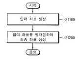
도 2를 참조하면, 본 발명의 일 실시예에 따른 터치 스크린에서의 노이즈 제거 방법은 터치 스크린상에서의 사용자의 연속적인 터치 동작에 따라 입력 좌표들을 생성하고(단계 S1100), 상기 터치 동작의 이동 방향 및 이동 속도에 따라 가변적으로 설정되는 유효 영역에 기초하여 상기 입력 좌표들을 필터링(filtering)하여 최종 좌표들을 생성한다(단계 S1200).Referring to FIG. 2, in the method of removing noise in a touch screen according to an embodiment of the present invention, input coordinates are generated according to a continuous touch operation of a user on the touch screen (step S1100), and a moving direction of the touch operation. And the final coordinates are generated by filtering the input coordinates based on the effective area that is variably set according to the moving speed (step S1200).
터치 스크린상에서 사용자가 터치를 유지한 상태에서 연속적으로 문자, 그림 등의 이미지를 입력하는 경우, 일정 주기에 따라 주기적으로 사용자의 터치 위치에 따른 상기 입력 좌표들을 생성할 수 있다.When the user continuously inputs an image such as a text or a picture while maintaining a touch on the touch screen, the input coordinates according to the touch position of the user may be periodically generated according to a predetermined period.
상기 터치 동작의 이동 방향 및 이동 속도에 따라 가변적으로 설정되는 유효 영역에 기초하여 상기 입력 좌표들을 선택적으로 제거함으로써 최종 좌표들을 생성할 수 있다. 상기 최종 좌표들은 터치 스크린에 의해 사용자의 터치 위치로 최종적으로 결정된 좌표들을 나타낸다.Final coordinates may be generated by selectively removing the input coordinates based on the effective area that is variably set according to the moving direction and the moving speed of the touch operation. The final coordinates represent coordinates finally determined by the touch screen as the user's touch position.
도 3a는 도 2의 입력 좌표들을 생성하는 단계(S1100)의 일 예를 나타내는 순 서도이다.3A is a flowchart illustrating an example of generating input coordinates of FIG. 2 (S1100).
도 3a를 참조하면, 입력 좌표들을 생성하는 단계(S1100)에서는 상기 터치 스크린상에서의 사용자의 터치 위치를 검출하여 현재 검출 좌표를 생성하고(단계 S1110), 상기 현재 검출 좌표가 직전 최종 좌표를 중심으로 하는 보정 영역에 포함되는지 여부에 기초하여 현재 입력 좌표를 결정할 수 있다(단계 S1120).Referring to FIG. 3A, in operation S1100, input coordinates are detected to generate a current detection coordinate by detecting a user's touch position on the touch screen (step S1110), and the current detection coordinate is centered on the last final coordinate. The current input coordinates can be determined based on whether or not it is included in the correction region (step S1120).
상기 직전 최종 좌표는 상기 최종 좌표들을 생성하는 과정에 있어서 이미 생성된 상기 최종 좌표들 중에서 바로 직전에 최종 좌표로 결정되었던 좌표를 나타낸다.The last final coordinate indicates a coordinate that was determined as the last coordinate immediately before the last among the final coordinates already generated in the process of generating the final coordinates.
도 3b는 도 3a의 현재 검출 좌표를 생성하는 단계(S1100)의 일 예를 나타내는 순서도이다.FIG. 3B is a flowchart illustrating an example of generating the current detection coordinates of FIG. 3A (S1100).
도 3b를 참조하면, 현재 검출 좌표를 생성하는 단계(S1110)에서는 상기 터치 스크린상에서의 사용자의 터치 위치를 n(n은 양의 정수)회 샘플링하여 n개의 좌표 샘플들을 생성한다(단계 S1111).Referring to FIG. 3B, in step S1110 of generating current detection coordinates, n coordinate samples are generated by sampling a user's touch position on the touch screen n times (n is a positive integer) (step S1111).
상기 설명한 바와 같이, 터치 스크린상에서 사용자가 터치를 유지한 상태에서 연속적으로 문자, 그림 등의 이미지를 입력하는 경우, 주기적으로 사용자의 터치 위치에 따른 상기 입력 좌표들을 생성할 수 있다. 상기 입력 좌표들 각각을 생성하기 위해, 터치 스크린상에서의 사용자의 터치 위치를 매 주기마다 n회 샘플링하여 생성된 상기 n개의 좌표 샘플들을 사용할 수 있다.As described above, when the user continuously inputs an image such as a text or a picture while maintaining the touch on the touch screen, the input coordinates according to the touch position of the user may be periodically generated. In order to generate each of the input coordinates, the n coordinate samples generated by sampling the user's touch position on the touch screen n times every cycle may be used.
상기 n개의 좌표 샘플들을 구성하는 n개의 제1 방향 좌표들 및 n개의 제2 방향 좌표들 중에서 각각 k(k는 n이하의 양의 정수)개의 제1 방향 좌표들 및 k개의 제2 방향 좌표들을 선택한다(단계 S1113).K (k is a positive integer less than or equal to n) first direction coordinates and k second direction coordinates among the n first direction coordinates and the n second direction coordinates constituting the n coordinate samples, respectively. (Step S1113).
상기 k개의 제1 방향 좌표들 및 k개의 제2 방향 좌표들을 선택하는 단계(S1113)에서는 상기 n개의 제1 방향 좌표들 및 n개의 제2 방향 좌표들을 각각 올림차순 또는 내림차순으로 소팅(sorting)하고(단계 S1115), 상기 소팅된 n개의 제1 방향 좌표들 및 n개의 제2 방향 좌표들 중에서 각각 중간 값에 해당하는 상기 k개의 제1 방향 좌표들 및 k개의 제2 방향 좌표들을 선택할 수 있다(단계 S1117).In the selecting of the k first direction coordinates and the k second direction coordinates (S1113), the n first direction coordinates and the n second direction coordinates are sorted in ascending or descending order, respectively ( In operation S1115, the k first direction coordinates and the k second direction coordinates corresponding to intermediate values may be selected from the sorted n first direction coordinates and n second direction coordinates, respectively. S1117).
상기 선택된 k개의 제1 방향 좌표들의 가중평균값을 상기 현재 검출 좌표의 제1 방향 좌표로 결정하고, 상기 선택된 k개의 제2 방향 좌표들의 가중평균값을 상기 현재 검출 좌표의 제2 방향 좌표로 결정할 수 있다(단계 S1119).The weighted average value of the selected k first direction coordinates may be determined as the first direction coordinates of the current detection coordinates, and the weighted average value of the selected k second direction coordinates may be determined as the second direction coordinates of the current detection coordinates. (Step S1119).
상기 제1 방향은 x축 방향으로 정의할 수 있고, 상기 제2 방향은 y축 방향으로 정의할 수 있으며, 이 때, 상기 제1 방향 좌표는 x좌표로 정의할 수 있고, 상기 제2 방향 좌표는 y좌표로 정의할 수 있다. 이하, 상기 제1 방향은 x축 방향으로 정의하고, 상기 제2 방향은 y축 방향으로 정의하여 설명한다.The first direction may be defined in the x-axis direction, the second direction may be defined in the y-axis direction, and in this case, the first direction coordinate may be defined in x-coordinate and the second direction coordinates. Can be defined by y coordinate. Hereinafter, the first direction is defined in the x-axis direction, and the second direction is defined in the y-axis direction.
예를 들어, n=8, k=4인 경우에 대한 도 3b의 현재 검출 좌표를 생성하는 단계(S1110)를 설명하면 아래와 같다.For example, the step (S1110) of generating the current detection coordinates of FIG. 3B for the case where n = 8 and k = 4 will be described below.
현재 주기에서 생성된 8개의 좌표 샘플들이 (x0, y0),......, (x7, y7)이고, x0 내지 x7을 올림차순 또는 내림차순으로 소팅하여 중간 값에 해당하는 4개의 x좌표인 세 번째 내지 여섯 번째 x좌표가 각각 xa1, xa2, xa3 및 xa4이고, y0 내지 y7을 올림차순 또는 내림차순으로 소팅하여 중간 값에 해당하는 4개의 y좌표인 세 번째 내지 여섯 번째 x좌표가 각각 yb1, yb2, yb3 및 yb4라고 하면, 아래의 [수학식 1]에 의해 xa1, xa2, xa3 및 xa4의 가중평균값을 상기 현재 검출 좌표의 x좌표로 결정하고, [수학식 2]에 의해 yb1, yb2, yb3 및 yb4의 가중평균값을 상기 현재 검출 좌표의 y좌표로 결정할 수 있다.The eight coordinate samples generated in the current period are (x0 , y0 ), ......, (x7 , y7 ), which corresponds to the intermediate value by sorting x0 to x7 in ascending or descending order. and the four x-coordinates of the third to sixth x coordinate respectively xa1, xa2, xa3, and xa4 to, y0 to y the four y coordinates sorted to7 in ascending order or descending order for the intermediate value If the third to sixth x coordinates are yb1 , yb2 , yb3 and yb4 , respectively, the weighted average of xa1 , xa2 , xa3 and xa4 is detected by Equation 1 below. It is determined by the x-coordinate of the coordinates, and the weighted average of yb1 , yb2 , yb3, and yb4 can be determined by the y coordinate of the current detection coordinates by Equation (2).
= (xa1 + 3*xa2 + 3*xa3 + xa4) / 8= (xa1 + 3 * xa2 + 3 * xa3 + xa4 ) / 8
= (yb1 + 3*yb2 + 3*yb3 + yb4) / 8= (yb1 + 3 * yb2 + 3 * yb3 + yb4 ) / 8
여기서, xC 및 yC는 각각 상기 현재 검출 좌표의 x좌표 및 y좌표를 나타낸다.Here, xC and yC represent the x coordinate and the y coordinate of the current detection coordinate, respectively.
상기 [수학식 1] 및 [수학식 2]에서는 x0 내지 x7을 올림차순 또는 내림차순으로 소팅하여 네 번째 및 다섯 번째의 x좌표(xa2, xa3) 및 y0 내지 y7을 올림차순 또는 내림차순으로 소팅하여 네 번째 및 다섯 번째의 y좌표(yb2, yb3)에 대해서는 3의 가중치를 가하고, x0 내지 x7을 올림차순 또는 내림차순으로 소팅하여 세 번째 및 여섯 번째의 x좌표(xa1, xa4) 및 y0 내지 y7을 올림차순 또는 내림차순으로 소팅하여 세 번째 및 여섯 번째의 y좌표(yb1, yb4)에 대해서는 1의 가중치를 가함으로써 시프트(shift) 연산을 통해 빠르게 상기 현재 검출 좌표를 생성할 수 있다.In Equations 1 and 2, x0 to x7 are sorted in ascending or descending order, so that the fourth and fifth x coordinates (xa2 , xa3 ) and y0 to y7 are in ascending or descending order. Sorting with the fourth and fifth y-coordinates (yb2 , yb3 ), weighting 3, and sorting x0 to x7 in ascending or descending order, so that the third and sixth x-coordinates (xa1 , xa4 ) and y0 to y7 sorted in ascending or descending order to detect the current quickly through a shift operation by adding a weight of 1 to the third and sixth y-coordinates (yb1 , yb4 ) You can create coordinates.
실시예에 따라서 가중치를 상기와 다르게 가하여 상기 현재 검출 좌표를 생성할 수도 있다.According to an embodiment, the current detection coordinates may be generated by applying a weight differently from the above.
도 3b를 참조하여 상기 설명한 바와 같이, 현재 검출 좌표를 생성하는 단계(S1110)는 n개의 좌표를 샘플링하고, 상기 n개의 좌표 샘플들을 소팅하여 중간 값에 해당하는 좌표 샘플들을 가중평균함으로써 상기 현재 검출 좌표를 생성하기 때문에, 사용자의 실제 터치 위치를 정확하게 검출할 수 있고, 상기 가중평균은 시프트 연산을 통해 수행되므로 빠른 속도로 상기 현재 검출 좌표를 생성할 수 있다.As described above with reference to FIG. 3B, the generating of the current detection coordinates (S1110) may include sampling the n coordinates, sorting the n coordinate samples, and weighting the coordinate samples corresponding to the median to detect the current detection. Since the coordinates are generated, the actual touch position of the user can be accurately detected, and the weighted average is performed through a shift operation, thereby generating the current detection coordinates at a high speed.
다시 도 3a를 참조하면, 상기 현재 입력 좌표를 결정하는 단계(S1120)는 상기 현재 검출 좌표가 상기 보정 영역에 포함되는지 여부를 판단하여(단계 S1130), 상기 현재 검출 좌표가 상기 보정 영역에 포함되는 경우, 상기 현재 검출 좌표 및 상기 직전 최종 좌표 사이의 거리에 기초하여 상기 현재 검출 좌표 및 상기 직전 최종 좌표 사이의 거리가 감소하도록 상기 현재 검출 좌표를 이동하여 상기 이동된 현재 검출 좌표를 상기 현재 입력 좌표로 결정하고(단계 S1140), 상기 현재 검출 좌표가 상기 보정 영역 외부에 위치하는 경우, 상기 현재 검출 좌표를 상기 현재 입력 좌표로 결정할 수 있다(단계 S1150).Referring back to FIG. 3A, in the determining of the current input coordinates (S1120), it is determined whether the current detection coordinates are included in the correction region (S1130), and the current detection coordinates are included in the correction region. In this case, the current detection coordinates are moved to reduce the distance between the current detection coordinates and the last final coordinates based on the distance between the current detection coordinates and the last final coordinates. If the current detection coordinates are located outside the correction area, the current detection coordinates may be determined as the current input coordinates (step S1150).
도 4a는 사용자가 빠른 속도로 직선을 입력한 경우 발생할 수 있는 터치 스 크린을 구비한 디스플레이 장치의 출력 결과의 일 예를 나타내는 도면이고, 도 4b는 사용자가 느린 속도로 직선을 입력한 경우 발생할 수 있는 터치 스크린을 구비한 디스플레이 장치의 출력 결과의 일 예를 나타내는 도면이다.FIG. 4A is a diagram illustrating an example of an output result of a display device having a touch screen that may occur when a user inputs a straight line at high speed, and FIG. 4B may occur when the user inputs a straight line at a slow speed. 4 is a diagram illustrating an example of an output result of a display device having a touch screen.
도 4a 및 도 4b에서 좌표(P1)는 상기 직전 최종 좌표를 나타내고, 좌표(P2)는 상기 직전 최종 좌표가 결정되기 직전에 최종 좌표로 결정되었던 좌표, 즉, 두 시점 이전의 최종 좌표를 나타내고, 좌표(P3)는 세 시점 이전의 최종 좌표를 나타낸다.In FIG. 4A and FIG. 4B, the coordinate P1 represents the last final coordinate, the coordinate P2 represents the coordinate which was determined as the last coordinate just before the last final coordinate was determined, that is, the last coordinate before two viewpoints, Coordinate P3 represents the final coordinate before three time points.
도 4a 및 도 4b에서 상기 두 시점 이전의 최종 좌표(P2)는 노이즈로 인해 사용자의 실제 터치 위치로부터 y축 방향으로 일정 거리(d)만큼 떨어진 위치로 검출된 것을 나타낸다.In FIG. 4A and FIG. 4B, the final coordinates P2 before the two viewpoints are detected as a position separated by a predetermined distance d in the y-axis direction from the user's actual touch position due to noise.
도 4a를 참조하면, 상기 세 시점 이전의 최종 좌표(P3)와 상기 두 시점 이전의 최종 좌표(P2) 사이의 거리가 먼 경우, 노이즈로 인한 출력의 왜곡 현상이 인식하지 못할 정도로 적게 나타난다.Referring to FIG. 4A, when the distance between the final coordinates P3 before the three viewpoints and the final coordinates P2 before the two viewpoints is far, the distortion of the output due to noise is not so small as to be recognized.
이에 반해, 도 4b를 참조하면, 상기 세 시점 이전의 최종 좌표(P3)와 상기 두 시점 이전의 최종 좌표(P2) 사이의 거리가 가까운 경우, 노이즈로 인한 출력의 왜곡현상이 뚜렷이 나타나고 이는 미세한 떨림으로 인식된다.On the contrary, referring to FIG. 4B, when the distance between the final coordinates P3 before the three viewpoints and the final coordinates P2 before the two viewpoints is close, distortion of the output due to noise appears clearly, which is a slight vibration. Is recognized.
따라서 현재 입력 좌표를 결정하는 단계(S1120)는 상기 현재 검출 좌표가 상기 직전 최종 좌표를 중심으로 하는 상기 보정 영역에 포함되는지 여부를 판단하여(단계 S1130) 상기 현재 검출 좌표가 상기 보정 영역에 포함되는 경우에만 상기 현재 검출 좌표의 위치를 보정할 수 있다.Accordingly, in the determining of the current input coordinates (S1120), it is determined whether the current detection coordinates are included in the correction region centered on the last final coordinate (step S1130), and the current detection coordinates are included in the correction region. Only when the position of the current detection coordinates can be corrected.
즉, 상기 현재 검출 좌표가 상기 직전 최종 좌표와 가까운 거리에 위치하는 경우에는 노이즈로 인한 미세 떨림이 육안으로 인식될 정도로 나타나므로 상기 현재 검출 좌표의 위치를 이동하여 상기 이동된 현재 검출 좌표를 상기 현재 입력 좌표로 결정하는 반면에(단계 S1140), 상기 현재 검출 좌표가 상기 직전 최종 좌표와 먼 거리에 위치하는 경우에는 노이즈가 발생하더라도 노이즈로 인한 출력의 왜곡 현상이 육안으로 인식될 정도로 나타나지 않으므로 동작 속도를 증가시키기 위해 상기 현재 검출 좌표의 위치를 이동하지 않고 상기 현재 검출 좌표를 상기 현재 입력 좌표로 결정할 수 있다(단계 S1150).That is, when the current detection coordinates are located at a distance close to the last final coordinates, fine shaking due to noise appears to be visually recognized, and thus the position of the current detection coordinates is moved to change the current detection coordinates. On the other hand, if the current detection coordinates are located far from the last final coordinates, even if noise occurs, the distortion of the output due to the noise does not appear to the naked eye. The current detection coordinates may be determined as the current input coordinates without moving the position of the current detection coordinates in order to increase (step S1150).
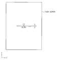
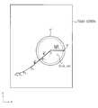
도 5a는 도 3a의 현재 입력 좌표를 결정하는 단계(S1120)를 설명하기 위한 도면이다.5A is a diagram for describing an operation S1120 of determining a current input coordinate of FIG. 3A.
도 5a에서 좌표(P1)는 상기 직전 최종 좌표를 나타내고, 좌표(C)는 상기 현재 검출 좌표를 나타낸다. 상기 보정 영역(A)은 상기 직전 최종 좌표(P1)를 중심으로 하여 x축 방향으로 2a(a는 양의 정수), y축 방향으로 2b(b는 양의 정수)의 길이를 갖는 직사각형 영역으로 설정될 수 있다.In FIG. 5A, coordinate P1 represents the last final coordinate, and coordinate C represents the current detection coordinate. The correction area A is a rectangular area having a length of 2a (a is a positive integer) in the x-axis direction and 2b (b is a positive integer) in the y-axis direction centering on the last final coordinate P1. Can be set.
예를 들면, x축 방향으로 480픽셀을 포함하고, y축 방향으로 800픽셀을 포함하는 터치 스크린의 경우 상기 보정 영역(A)의 x축 방향의 길이는 64픽셀, 즉, a=32, y축 방향의 길이는 128픽셀, 즉, b=64로 설정될 수 있다.For example, in the case of a touch screen including 480 pixels in the x axis direction and 800 pixels in the y axis direction, the length of the correction area A in the x axis direction is 64 pixels, that is, a = 32, y The length in the axial direction may be set to 128 pixels, that is, b = 64.
상기 현재 검출 좌표(C)가 상기 직전 최종 좌표(P1)를 중심으로 하는 상기 보정 영역(A)에 포함되는지 여부의 판단(단계 S1130)은 아래의 [수학식 3]에 의해 수행될 수 있다.The determination (step S1130) of whether the current detection coordinate C is included in the correction area A centering on the last final coordinate P1 may be performed by Equation 3 below.
여기서, 상기 직전 최종 좌표(P1)의 좌표는 (x1, y1)이고, 상기 현재 검출 좌표(C)의 좌표는 (xC, yC)이다.Here, the coordinates of the immediately preceding final coordinate P1 are (x1 , y1 ), and the coordinates of the current detection coordinate C are (xC , yC ).
상기 [수학식 3]을 만족하는 경우에는 상기 현재 검출 좌표(C)는 상기 직전 최종 좌표(P1)를 중심으로 하는 상기 보정 영역(A)에 포함되는 경우이므로 상기 현재 검출 좌표(C) 및 상기 직전 최종 좌표(P1) 사이의 거리에 기초하여 상기 현재 검출 좌표(C) 및 상기 직전 최종 좌표(P1) 사이의 거리가 감소하도록 상기 현재 검출 좌표(C)를 이동하여 상기 이동된 현재 검출 좌표를 상기 현재 입력 좌표로 결정할 수 있다(단계 S1140).When the equation (3) is satisfied, the current detection coordinate (C) is included in the correction area (A) centered on the last final coordinate (P1), and thus the current detection coordinate (C) and the Based on the distance between the last final coordinates P1, the current detection coordinates C are moved to decrease the distance between the current detection coordinates C and the last final coordinates P1 to reduce the moved current detection coordinates. The current input coordinate may be determined (step S1140).
반면에, 상기 [수학식 3]을 만족하지 않는 경우에는 상기 현재 검출 좌표(C)는 상기 직전 최종 좌표(P1)를 중심으로 하는 상기 보정 영역(A) 외부에 위치하는 경우이므로 상기 현재 검출 좌표(C)를 이동시키지 않고 상기 현재 검출 좌표(C)를 상기 현재 입력 좌표로 결정할 수 있다(단계 S1150).On the other hand, when the equation (3) is not satisfied, the current detection coordinate (C) is located outside the correction area (A) centered on the last final coordinate (P1), and thus the current detection coordinate (C). The current detection coordinate C may be determined as the current input coordinate without moving (C) (step S1150).
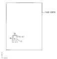
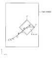
도 5b는 도 3a의 상기 이동된 현재 검출 좌표를 상기 현재 입력 좌표로 결정하는 단계(S1140)를 설명하기 위한 도면이다.FIG. 5B is a diagram for describing an operation (S1140) of determining the moved current detection coordinate of FIG. 3A as the current input coordinate.
도 5b에서 좌표(P1)는 상기 직전 최종 좌표를 나타내고, 좌표(C)는 상기 현재 검출 좌표를 나타내고, 좌표(S)는 상기 이동된 현재 검출 좌표를 나타내는 것으로서 상기 이동된 현재 검출 좌표는 상기 현재 입력 좌표(S)로 결정된다.In FIG. 5B, coordinate P1 represents the last final coordinate, coordinate C represents the current detection coordinate, and coordinate S represents the moved current detection coordinate, and the moved current detection coordinate is the current. It is determined by the input coordinate S.
도 5b를 참조하면, 상기 현재 검출 좌표(C) 및 상기 직전 최종 좌표(P1) 사이의 거리에 기초하여 상기 현재 검출 좌표(C) 및 상기 직전 최종 좌표(P1) 사이의 거리가 감소하도록 상기 현재 검출 좌표(C)를 이동하여 상기 이동된 현재 검출 좌표를 상기 현재 입력 좌표(S)로 결정할 수 있다.Referring to FIG. 5B, the distance between the current detection coordinate C and the last final coordinate P1 is decreased based on the distance between the current detection coordinate C and the last final coordinate P1. The detected coordinate C may be moved to determine the moved current detected coordinate as the current input coordinate S.
상기 현재 입력 좌표(S)는 아래의 [수학식 4] 및 [수학식 5]에 의해 결정될 수 있다.The current input coordinate S may be determined by Equations 4 and 5 below.
여기서, 상기 직전 최종 좌표(P1)의 좌표는 (x1, y1)이고, 상기 현재 검출 좌표(C)의 좌표는 (xC, yC)이고, 상기 현재 입력 좌표(S)의 좌표는 (xS, yS)이다.Here, the coordinates of the immediately preceding final coordinates P1 are (x1 , y1 ), the coordinates of the current detection coordinates C are (xC , yC ), and the coordinates of the current input coordinates S are (xS , yS ).
즉, 상기 현재 입력 좌표(S)가 상기 직전 최종 좌표(P1)로부터 x축 방향으로 떨어진 거리(|xS-x1|)에 대한 상기 현재 검출 좌표(C)가 상기 직전 최종 좌표(P1)로부터 x축 방향으로 떨어진 거리(|xC-x1|)의 비율은, 상기 현재 검출 좌표(C)가 상기 직전 최종 좌표(P1)로부터 x축 방향으로 떨어진 거리(|xC-x1|)에 대한 상기 직전 최종 좌표(P1)로부터 x축 방향으로 상기 보정 영역(A)의 경계까지의 거리(a)의 비율과 동일하도록 상기 현재 입력 좌표(S)의 x좌표를 결정할 수 있다.That is, the current detection coordinate C for the distance (| xS -x1 |) in which the current input coordinate S is separated in the x-axis direction from the last final coordinate P1 is the last final coordinate P1. from a distance in the x-axis direction (| xC -x1 |) ratio is, a distance of the current detection coordinates (C) is the x-axis direction from the immediately preceding the final coordinates(P1) (| x C -x 1 | The x coordinate of the current input coordinate S may be determined to be equal to the ratio of the distance a from the immediately preceding final coordinate P1 to the boundary of the correction area A in the x-axis direction.
마찬가지로, 상기 현재 입력 좌표(S)가 직전 입력 좌표(P1)로부터 y축 방향으로 떨어진 거리(|yS-y1|)에 대한 터치 좌표(C)가 직전 입력 좌표(P1)로부터 y축 방향으로 떨어진 거리(|yC-y1|)의 비율은, 터치 좌표(C)가 직전 입력 좌표(P1)로부터 y축 방향으로 떨어진 거리(|yC-y1|)에 대한 직전 입력 좌표(P1)로부터 y축 방향으로 일정 영역(A)의 경계까지의 거리(b)의 비율과 동일하도록 상기 현재 입력 좌표(S)의 y좌표를 결정할 수 있다.Similarly, the touch coordinate C for the distance (| yS -y1 |) away from the previous input coordinate P1 in the y-axis direction from the previous input coordinate P1 is in the y-axis direction from the previous input coordinate P1. a distance (| yC -y1 |) ratio is, the touch coordinates (C) immediately before the input coordinate distance in the y-axis direction from the (P1) of (| yC -y1 |) immediately before the input of the coordinates ( The y-coordinate of the current input coordinate S may be determined to be equal to the ratio of the distance b from P1) to the boundary of the predetermined area A in the y-axis direction.
도 5a 및 도 5b를 참조하여 상기 보정 영역은 직사각형의 영역인 경우를 예로 들어 설명하였으나, 실시예에 따라서 상기 보정 영역은 상기 직전 최종 좌표를 중심으로 하는 원형의 영역 또는 타원형의 영역 등 다른 형상의 영역으로 설정될 수도 있다.5A and 5B, the correction area is a rectangular area. For example, the correction area may have a circular shape or an elliptical area centered on the last final coordinate. It may be set to an area.
도 6a는 도 3a의 현재 입력 좌표를 결정하는 단계(S1120)가 적용되지 않은 경우에 대한 터치 스크린을 구비한 디스플레이 장치의 출력 결과의 일 예를 나타내는 도면이다.FIG. 6A is a diagram illustrating an example of an output result of a display device having a touch screen when the step (S1120) of determining the current input coordinate of FIG. 3A is not applied.
도 6a에서 사각형의 칸들 각각은 상기 디스플레이 장치의 픽셀들 각각을 나타낸다.In FIG. 6A, each of the square cells represents each of the pixels of the display device.
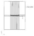
도 6a를 참조하면, 사용자가 픽셀과 픽셀의 경계선(z)을 따라 x축 방향으로 직선을 그은 경우, 상기 입력 좌표들은 터치한 좌표 검출시 발생하는 노이즈로 인해 경계선(z)의 위쪽에 있는 픽셀 또는 경계선(z)의 아래쪽에 있는 픽셀로 불규칙적으로 결정된다.Referring to FIG. 6A, when a user draws a straight line in the x-axis direction along a pixel boundary line z, the input coordinates are pixels above the boundary line z due to noise generated when the touched coordinate is detected. Or irregularly determined by pixels under the boundary z.
따라서 도 6a에 도시된 바와 같이, 현재 입력 좌표를 결정하는 단계(S1120)가 적용되지 않은 경우, 터치 스크린을 구비한 디스플레이 장치의 출력 결과에 미세한 떨림 현상이 발생하게 된다.Therefore, as illustrated in FIG. 6A, when the step (S1120) of determining the current input coordinates is not applied, a slight shaking phenomenon occurs in the output result of the display device having the touch screen.
도 6b는 도 3a의 현재 입력 좌표를 결정하는 단계(S1120)가 적용된 경우에 대한 터치 스크린을 구비한 디스플레이 장치의 출력 결과의 일 예를 나타내는 도면이다.FIG. 6B is a diagram illustrating an example of an output result of a display device having a touch screen in the case where the step (S1120) of determining the current input coordinate of FIG. 3A is applied.
도 6b에서 사각형의 칸들 각각은 상기 디스플레이 장치의 픽셀들 각각을 나타낸다.In FIG. 6B, each of the square cells represents each of the pixels of the display device.
도 6b를 참조하면, 사용자가 픽셀과 픽셀의 경계선(z)을 따라 x축 방향으로 직선을 그은 경우, 터치한 좌표 검출시 발생하는 노이즈로 인해 상기 현재 검출 좌표가 경계선(z)의 위쪽에 있는 픽셀 또는 경계선(z)의 아래쪽에 있는 픽셀로 불규칙적으로 결정되더라도, 현재 입력 좌표를 결정하는 단계(S1120)를 통해, 상기 현재 검출 좌표 및 상기 직전 최종 좌표 사이의 거리에 기초하여 상기 현재 검출 좌표 및 상기 직전 최종 좌표 사이의 거리가 감소하도록 상기 현재 검출 좌표를 이동하여 상기 이동된 현재 검출 좌표를 상기 현재 입력 좌표로 결정함으로써 노이즈가 제거되므로 상기 디스플레이 장치의 출력 결과에 미세한 떨림 현상이 발생하지 않는다.Referring to FIG. 6B, when the user draws a straight line in the x-axis direction along the boundary line z of the pixel, the current detection coordinate is located above the boundary line z due to noise generated when the touched coordinate is detected. Even if irregularly determined by the pixel or the pixel below the boundary z, through the step (S1120) of determining the current input coordinates, the current detection coordinates and the current detection coordinates based on the distance between the current detection coordinates and the last final coordinates Since the noise is removed by moving the current detection coordinates to determine the moved current detection coordinates as the current input coordinates so that the distance between the last final coordinates is reduced, minute shaking does not occur in the output result of the display device.
도 6b에서는 상기 경계선(z)의 위쪽에 있는 픽셀 상에 직선이 출력된 것을 나타내고 있으나, 직선상의 최초의 픽셀이 상기 경계선(z)의 아래쪽에 있는 픽셀로 결정된 경우에는 상기 경계선(z)의 아래쪽에 있는 픽셀 상에 직선이 출력될 수도 있다.In FIG. 6B, a straight line is output on a pixel above the boundary line z. However, when the first pixel on the straight line is determined to be a pixel below the boundary line z, the bottom line of the boundary line z is determined. A straight line may be output on the pixel at.
도 2 내지 6B를 참조하여 설명한 바와 같이, 도 2의 본 발명의 일 실시예에 따른 터치 스크린에서의 노이즈 제거 방법은, 상기 현재 검출 좌표와 상기 직전 최종 좌표와의 위치 관계에 따라 선택적으로 상기 현재 검출 좌표 및 상기 직전 최종 좌표 사이의 거리에 기초하여 상기 현재 검출 좌표 및 상기 직전 최종 좌표 사이의 거리가 감소하도록 상기 현재 검출 좌표를 이동하여 상기 이동된 현재 검출 좌표를 상기 현재 입력 좌표로 결정함으로써, 터치 스크린의 속도를 저하시키지 않으면서 터치한 좌표 검출시 발생하는 노이즈로 인한 미세한 떨림 현상을 효과적으로 제거할 수 있다.As described with reference to FIGS. 2 to 6B, the method for removing noise in a touch screen according to an exemplary embodiment of the present invention of FIG. 2 may be performed according to a positional relationship between the current detection coordinates and the last final coordinates. By moving the current detection coordinates to reduce the distance between the current detection coordinates and the last final coordinates based on the distance between the detection coordinates and the last final coordinates to determine the moved current detection coordinates as the current input coordinates, Without reducing the speed of the touch screen, it is possible to effectively remove the minute shaking caused by the noise generated when the touched coordinates are detected.
도 7은 도 2의 최종 좌표들을 생성하는 단계(S1200)의 일 예를 나타내는 순서도이다.FIG. 7 is a flowchart illustrating an example of generating final coordinates of FIG. 2 (S1200).
도 7을 참조하면, 최종 좌표들을 생성하는 단계(S1200)에서는 이전 최종 좌표들에 기초하여 사용자의 움직임을 나타내는 모션 벡터(motion vector)를 결정한다(단계 S1210). 상기 모션 벡터에 기초하여 상기 유효 영역을 설정하고(단계 S1220), 현재 입력 좌표가 상기 유효 영역에 포함되는지 여부를 판단한다(단계 S1230). 상기 현재 입력 좌표가 상기 유효 영역에 포함되는 경우, 상기 현재 입력 좌표를 현재 최종 좌표로 결정할 수 있다(단계 S1240). 상기 현재 입력 좌표가 상기 유효 영역 외부에 위치하는 경우, 상기 현재 입력 좌표를 노이즈에 의한 좌표로 결정하여 상기 현재 입력 좌표를 제거하고 상기 현재 최종 좌표를 생성하지 않을 수 있다(단계 S1250).Referring to FIG. 7, in generating the final coordinates (S1200), a motion vector representing the motion of the user is determined based on the previous final coordinates (S1210). The valid region is set based on the motion vector (step S1220), and it is determined whether a current input coordinate is included in the valid region (step S1230). When the current input coordinate is included in the valid area, the current input coordinate may be determined as the current final coordinate (step S1240). When the current input coordinate is located outside the valid area, the current input coordinate may be determined as a coordinate due to noise to remove the current input coordinate and not generate the current final coordinate (step S1250).
이하, 도 7의 각 단계에 대해 상세히 설명한다.Hereinafter, each step of FIG. 7 will be described in detail.
도 8은 도 7의 모션 벡터를 결정하는 단계(S1210)를 설명하기 위한 도면이다.FIG. 8 is a diagram for describing an operation S1210 of determining the motion vector of FIG. 7.
도 8에서 좌표(P1)는 상기 최종 좌표들을 생성하는 과정에 있어서 이미 생성된 상기 최종 좌표들 중에서 바로 직전에 최종 좌표로 결정되었던 직전 최종 좌표를 나타내고, 좌표(P2)는 상기 직전 최종 좌표가 결정되기 직전에 최종 좌표로 결정되었던 좌표, 즉, 두 시점 이전의 최종 좌표를 나타내고, 좌표(P3)는 세 시점 이전의 최종 좌표를 나타내고, 좌표(P4)는 네 시점 이전의 최종 좌표를 나타내고, 좌표(P5)는 다섯 시점 이전의 최종 좌표를 나타낸다.In FIG. 8, the coordinate P1 represents the last final coordinate determined immediately before the last coordinate among the final coordinates already generated in the process of generating the final coordinates, and the coordinate P2 is determined by the last final coordinate. Coordinates that were determined as final coordinates immediately before becoming, that is, final coordinates before two viewpoints, coordinate P3 denotes final coordinates before three viewpoints, coordinate P4 denotes final coordinates before four viewpoints, and (P5) represents the final coordinates before five time points.
도 8을 참조하면, 상기 모션 벡터는 상기 두 시점 이전의 최종 좌표(P2)를 시점으로 하고, 상기 직전 최종 좌표(P1)를 종점으로 하는 벡터(M)로 결정될 수 있다.Referring to FIG. 8, the motion vector may be determined as a vector M having the final coordinates P2 before the two viewpoints as the starting point and the last final coordinate P1 as the end point.
상기 모션 벡터는 터치 스크린상에서의 사용자의 연속적인 터치 동작에 있어서, 터치 위치가 터치 스크린상에서 이동하는 방향 및 속도를 나타낸다.The motion vector represents the direction and speed at which the touch position moves on the touch screen in the user's continuous touch operation on the touch screen.
도 9 내지 도 11은 도 7의 유효 영역을 설정하는 단계(S1220)를 설명하기 위한 도면이다.9 to 11 are diagrams for describing an operation S1220 of setting an effective area of FIG. 7.
도 9 내지 도 11에서 좌표(P1)는 상기 직전 최종 좌표를 나타내고, 좌표(P2)는 상기 두 시점 이전의 최종 좌표를 나타내고, 좌표(P3)는 세 시점 이전의 최종 좌표를 나타내고, 좌표(P4)는 네 시점 이전의 최종 좌표를 나타내고, 좌표(P5)는 다섯 시점 이전의 최종 좌표를 나타낸다.In FIG. 9 to FIG. 11, the coordinate P1 represents the last final coordinate, the coordinate P2 represents the final coordinate before the two viewpoints, the coordinate P3 represents the final coordinate before three viewpoints, and the coordinate P4. ) Denotes the final coordinates before four viewpoints, and coordinate P5 denotes the final coordinates before five viewpoints.
도 9를 참조하면, 상기 직전 최종 좌표(P1)를 시점으로 하는 상기 모션 벡터(M)의 종점(O)을 중심으로 하고, 상기 모션 벡터의 크기(|M|)를 반지름으로 하는 원형의 영역(V)을 상기 유효 영역으로 고려할 수 있다.Referring to FIG. 9, a circular region centered on an end point O of the motion vector M having the last final coordinate P1 as a starting point and a radius of the size of the motion vector | M | (V) can be considered as the effective area.
그러나 사용자가 한 지점에서 터치한 상태에서 일정 시간 동안 정지한 후 이미지를 입력하기 위해 이동을 하는 경우, 상기 직전 최종 좌표(P1) 및 상기 두 시점 이전의 최종 좌표(P2)는 서로 동일하게 되어 상기 모션 벡터(M)는 영벡터가 된다. 이러한 경우 상기 유효 영역(V)의 면적이 0이 된다는 문제점이 있다.However, when the user moves to input an image after stopping for a predetermined time while touching at a point, the last final coordinate P1 and the last coordinate P2 before the two viewpoints become equal to each other. The motion vector M becomes a zero vector. In this case, there is a problem that the area of the effective area V becomes zero.
도 10은 상기 문제점을 해결하기 위한 상기 유효 영역을 설정하는 방법을 나타낸다.10 shows a method of setting the effective area for solving the problem.
도 10에서 좌표(S)는 상기 현재 입력 좌표를 나타낸다.Coordinate S in FIG. 10 represents the current input coordinate.
도 10을 참조하면, 상기 직전 최종 좌표(P1)를 시점으로 하는 상기 모션 벡터(M)의 종점(O)을 중심으로 하고, 상기 모션 벡터의 크기(|M|)에 일정 상수(e)(e는 양의 정수)를 더한 값을 반지름으로 하는 원형의 영역(V')을 상기 유효 영역으로 설정할 수 있다.Referring to FIG. 10, a constant constant e is defined by the end point O of the motion vector M having the last final coordinate P1 as a starting point, and the size of the motion vector | M | e can set the circular area | region V 'which makes the radius plus the positive integer) the said effective area | region.
도 10과 관련하여 설명한 방법에 의해 상기 유효 영역을 설정하는 경우, 상기 유효 영역(V')의 중점(O) 및 상기 현재 입력 좌표(S) 사이의 유클리디언 거리(Euclidean Distance)가 상기 모션 벡터의 크기(|M|)에 일정 상수(e)를 더한 값보다 큰지 여부를 결정함으로써 상기 현재 입력 좌표(S)가 상기 유효 영역(V')에 포함되는지 여부를 판단(단계 S1230)할 수 있다.When the valid region is set by the method described with reference to FIG. 10, an Euclidean distance between the midpoint O of the valid region V ′ and the current input coordinate S is determined by the motion. It may be determined whether the current input coordinate S is included in the valid area V ′ by determining whether or not the current input coordinate S is included in the effective area V ′ by determining whether or not the magnitude of the vector is greater than a constant constant e. have.
도 10과 관련하여 설명한 상기 유효 영역 설정 방법에 따르면, 상기 유효 영 역(V')의 중점(O) 및 상기 현재 입력 좌표(S) 사이의 유클리디언 거리를 구하는 데에 많은 시간이 소요되어 터치 스크린의 동작 속도가 저하될 가능성이 있으므로, 도 11에서는 터치 스크린의 동작 속도를 보다 증가시킬 수 있는 상기 유효 영역을 설정하는 방법을 나타낸다.According to the effective area setting method described with reference to FIG. 10, it takes a long time to determine the Euclidean distance between the midpoint O of the effective area V 'and the current input coordinate S. Since the operating speed of the touch screen may be lowered, FIG. 11 illustrates a method of setting the effective area that can further increase the operating speed of the touch screen.
도 11을 참조하면, 상기 직전 최종 좌표(P1)를 시점으로 하는 상기 모션 벡터(M)의 종점(O)을 중심으로 하고, 상기 모션 벡터의 크기(|M|)에 일정 상수(e)를 더한 값의 두 배를 대각선의 길이로 갖는 정사각형의 영역(V'')을 상기 유효 영역으로 설정할 수 있다.Referring to FIG. 11, a constant constant e is added to the magnitude (| M |) of the motion vector centered on the end point O of the motion vector M having the last final coordinate P1 as a starting point. The square area V ″ having twice the sum of the diagonals can be set as the effective area.
이 경우, 상기 유효 영역(V'')의 중점(O) 및 상기 현재 입력 좌표(S) 사이의 맨하탄 거리(Manhattan Distance)가 상기 유효 영역(V'')의 꼭지점과 상기 유효 영역의 중점(O) 사이의 맨하탄 거리보다 큰지 여부를 결정함으로써 상기 현재 입력 좌표(S)가 상기 유효 영역(V'')에 포함되는지 여부를 판단(단계 S1230)할 수 있다.In this case, a Manhattan distance between the midpoint O of the valid area V ″ and the current input coordinate S is a vertex of the valid area V ″ and a midpoint of the valid area V ′. It is possible to determine whether the current input coordinate S is included in the effective area V '' by determining whether the distance is greater than the distance between Manhattan and O (step S1230).
즉, 아래의 [수학식 6]을 만족하는 경우, 상기 현재 입력 좌표(S)는 상기 유효 영역(V'')에 포함되므로, 상기 현재 입력 좌표(S)를 상기 현재 최종 좌표로 결정하고(단계 S1240), 아래의 [수학식 6]을 만족하지 않는 경우, 상기 현재 입력 좌표(S)는 상기 유효 영역(V'')에 포함되지 않으므로, 상기 현재 입력 좌표(S)를 노이즈에 의한 좌표로 결정하고 상기 현재 입력 좌표(S)를 제거할 수 있다(단계 S1250).That is, when the following Equation 6 is satisfied, the current input coordinate S is included in the effective area V ″, and the current input coordinate S is determined as the current final coordinate ( In operation S1240, when the following Equation 6 is not satisfied, the current input coordinate S is not included in the effective area V ″, and thus the current input coordinate S is coordinated by noise. It is determined that the current input coordinate (S) can be removed (step S1250).
여기서, 상기 유효 영역의 중심의 좌표는 (xO, yO)이고, 상기 현재 입력 좌표는 (xS, yS)이다.Here, the coordinate of the center of the effective area is (xO , yO ), and the current input coordinate is (xS , yS ).
일반적으로 터치 스크린상에서 사용자가 연속적으로 문자, 그림 등의 이미지를 입력하는 경우, 사용자의 움직임의 이동 방향 및 이동 속도에 따라 상기 현재 입력 좌표가 위치할 수 있는 영역이 결정된다. 다시 말하면, 사용자가 터치 스크린상에서 연속적인 이미지를 그리는 경우, 사용자의 움직임이 이동하던 방향, 즉, 상기 모션 벡터 방향의 영역에 상기 현재 입력 좌표가 위치할 가능성이 높고, 또한 사용자의 움직임의 이동 속도가 빠를수록, 즉, 상기 모션 벡터의 크기가 클수록 상기 현재 입력 좌표가 위치할 수 있는 영역이 넓어진다.In general, when a user continuously inputs an image such as a text or a picture on the touch screen, an area in which the current input coordinate may be located is determined according to the moving direction and the moving speed of the user's movement. In other words, when the user draws a continuous image on the touch screen, it is highly likely that the current input coordinates are located in the direction in which the user's movement is moving, that is, in the region of the motion vector direction, and the movement speed of the user's movement. The faster, that is, the larger the size of the motion vector, the wider the area where the current input coordinate can be located.
따라서 도 2 및 도 7 내지 11을 참조하여 설명한 바와 같이, 도 2의 본 발명의 일 실시예에 따른 터치 스크린에서의 노이즈 제거 방법은, 상기 이전 최종 좌표들에 기초하여 사용자의 움직임을 나타내는 상기 모션 벡터를 결정하고, 상기 모션 벡터에 기초하여 상기 유효 영역을 설정하여, 사용자의 움직임에 따라 상기 현재 입력 좌표가 위치할 수 있는 상기 유효 영역의 위치 및 크기를 상이하게 설정함으로써, 연속적인 이미지를 입력하는 경우 입력의 시점 및 종점에서 주로 발생하는 비정상적으로 튀는 현상, 즉, 입력된 지점과 무관한 지점의 좌표가 터치된 것으로 검출되어 이미지가 왜곡되는 현상을 효과적으로 제거할 수 있다.Therefore, as described with reference to FIGS. 2 and 7 to 11, the noise removing method of the touch screen according to the exemplary embodiment of the present invention of FIG. 2 may include the motion indicating the user's movement based on the previous final coordinates. A continuous image is input by determining a vector, setting the valid region based on the motion vector, and differently setting positions and sizes of the valid region in which the current input coordinates can be positioned according to a user's movement. In this case, it is possible to effectively eliminate the phenomenon in which an image is distorted because an abnormal splash, which occurs mainly at an input point and an end point of the input, that is, a coordinate of a point irrelevant to an input point is detected as being touched.
도 12는 본 발명의 일 실시예에 따른 터치 스크린을 구비한 디스플레이 장치 에서의 터치 동작 디스플레이 방법을 나타내는 순서도이다.12 is a flowchart illustrating a touch operation display method in a display device with a touch screen according to an embodiment of the present invention.
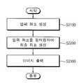
도 12를 참조하면, 본 발명의 일 실시예에 따른 터치 스크린을 구비한 디스플레이 장치에서의 터치 동작 디스플레이 방법은 터치 스크린상에서 사용자의 연속적인 터치 동작에 따라 입력 좌표들을 생성하고(단계 S2100), 상기 터치 동작의 이동 방향 및 이동 속도에 따라 가변적으로 설정되는 유효 영역에 기초하여 상기 입력 좌표들을 필터링하여 최종 좌표들을 생성하고(단계 S2200), 상기 최종 좌표들에 기초하여 상기 사용자의 연속적인 터치 동작에 따른 이미지를 출력한다(단계 S2300).Referring to FIG. 12, in the method of displaying a touch motion in a display device with a touch screen according to an embodiment of the present invention, input coordinates are generated according to a continuous touch motion of a user on a touch screen (step S2100). The final coordinates are generated by filtering the input coordinates based on the effective area that is variably set according to the moving direction and the moving speed of the touch operation (step S2200). The corresponding image is output (step S2300).
입력 좌표들을 생성하는 단계(S2100)에서는 상기 터치 스크린상에서의 사용자의 터치 위치를 검출하여 현재 검출 좌표를 생성하고, 상기 현재 검출 좌표가 직전 최종 좌표를 중심으로 하는 보정 영역에 포함되는 경우, 상기 현재 검출 좌표 및 상기 직전 최종 좌표 사이의 거리에 기초하여 상기 현재 검출 좌표 및 상기 직전 최종 좌표 사이의 거리가 감소하도록 상기 현재 검출 좌표를 이동하여 상기 이동된 현재 검출 좌표를 상기 현재 입력 좌표로 결정하고, 상기 현재 검출 좌표가 상기 보정 영역 외부에 위치하는 경우, 상기 현재 검출 좌표를 상기 현재 입력 좌표로 결정할 수 있다.In the generating of the input coordinates (S2100), current detection coordinates are generated by detecting a user's touch position on the touch screen, and when the current detection coordinates are included in a correction area centered on the last final coordinate, the current Determine the moved current detection coordinates as the current input coordinates by moving the current detection coordinates so as to reduce the distance between the current detection coordinates and the last final coordinates based on a distance between the detection coordinates and the last final coordinates; When the current detection coordinates are located outside the correction area, the current detection coordinates may be determined as the current input coordinates.
상기 직전 최종 좌표는 상기 최종 좌표들을 생성하는 과정에 있어서 이미 생성된 상기 최종 좌표들 중에서 바로 직전에 최종 좌표로 결정되었던 좌표를 나타낸다.The last final coordinate indicates a coordinate that was determined as the last coordinate immediately before the last among the final coordinates already generated in the process of generating the final coordinates.
입력 좌표들을 생성하는 단계(S2100)에서는 도 2 내지 도 6b와 관련하여 설 명한 단계(S1100)와 동일하게 수행될 수 있다. 도 2 내지 도 6b와 관련하여 단계(S1100)에 대해 상세히 설명하였으므로, 중복을 피하기 위해 여기서는 상세한 설명은 생략한다.In operation S2100, the input coordinates may be performed in the same manner as the operation S1100 described with reference to FIGS. 2 to 6B. Since step S1100 has been described in detail with reference to FIGS. 2 to 6B, detailed descriptions thereof will be omitted herein to avoid duplication.
최종 좌표들을 생성하는 단계(S2200)에서는 이전 최종 좌표들에 기초하여 사용자의 움직임을 나타내는 모션 벡터를 결정하고, 상기 모션 벡터에 기초하여 상기 유효 영역을 설정하고, 현재 입력 좌표가 상기 유효 영역에 포함되는지 여부를 판단하여, 상기 현재 입력 좌표가 상기 유효 영역에 포함되는 경우, 상기 현재 입력 좌표를 현재 최종 좌표로 결정하고, 상기 현재 입력 좌표가 상기 유효 영역 외부에 위치하는 경우, 상기 현재 입력 좌표를 노이즈에 의한 좌표로 결정하고 상기 현재 입력 좌표를 제거할 수 있다.In generating final coordinates (S2200), a motion vector representing a user's movement is determined based on previous final coordinates, the valid region is set based on the motion vector, and a current input coordinate is included in the valid region. Determine whether the current input coordinate is included in the valid area, and determine the current input coordinate as a current final coordinate, and when the current input coordinate is located outside the valid area, determine the current input coordinate. The coordinates due to noise may be determined and the current input coordinates may be removed.
최종 좌표들을 생성하는 단계(S2200)는 도 2 및 도 7 내지 도 11과 관련하여 설명한 단계(S1200)와 동일하게 수행될 수 있다. 도 2 및 도 7 내지 도 11과 관련하여 단계(S1200)에 대해 상세히 설명하였으므로, 중복을 피하기 위해 여기서는 상세한 설명은 생략한다.Generating final coordinates (S2200) may be performed in the same manner as in operation S1200 described with reference to FIGS. 2 and 7 through 11. Since step S1200 has been described in detail with reference to FIGS. 2 and 7 to 11, a detailed description thereof will be omitted herein to avoid duplication.
상기 터치 스크린을 구비한 디스플레이 장치는 입력 좌표들을 생성하는 단계(S2100) 및 최종 좌표들을 생성하는 단계(S2200)를 통해 생성된 상기 최종 좌표들에 기초하여 상기 사용자의 연속적인 터치 동작에 따른 이미지를 출력한다(단계 S2300). 이 때, 상기 현재 최종 좌표가 상기 사용자의 연속적인 터치 동작 중에 최초로 생성된 최종 좌표인 경우, 상기 디스플레이 장치는 상기 현재 최종 좌표에 해당하는 화면상의 위치에 점을 디스플레이하고, 상기 현재 최종 좌표가 상기 최초로 생성된 최종 좌표 이후에 생성된 최종 좌표인 경우, 상기 디스플레이 장치는 상기 현재 최종 좌표와 상기 직전 최종 좌표를 연결하는 직선을 디스플레이할 수 있다.The display device having the touch screen displays an image according to the continuous touch operation of the user based on the final coordinates generated through generating input coordinates (S2100) and generating final coordinates (S2200). Output (step S2300). In this case, when the current final coordinates are the last coordinates generated during the continuous touch operation of the user, the display device displays a point at a position on the screen corresponding to the current final coordinates, and the current final coordinates are In the case of final coordinates generated after the first generated final coordinates, the display device may display a straight line connecting the current final coordinates with the last final coordinates.
도 12의 터치 스크린을 구비한 디스플레이 장치에서의 터치 동작 디스플레이 방법은 노트북, 휴대폰, PDA(Personal Digital Assistant), MP3 플레이어 등과 같이 터치 스크린 장치를 구비하는 임의의 디스플레이 장치에 적용될 수 있다.The touch operation display method in the display device with a touch screen of FIG. 12 may be applied to any display device including a touch screen device such as a notebook computer, a mobile phone, a personal digital assistant (PDA), an MP3 player, and the like.
또한, 도 12의 터치 스크린을 구비한 디스플레이 장치에서의 터치 동작 디스플레이 방법은 감압식 터치 스크린 및 정전식 터치 스크린을 포함하는 모든 종류의 터치 스크린을 구비하는 디스플레이 장치에 적용될 수 있다.In addition, the touch operation display method in the display device with a touch screen of FIG. 12 may be applied to a display device having all kinds of touch screens including a pressure sensitive touch screen and a capacitive touch screen.
도 13은 본 발명의 일 실시예에 따른 터치 스크린에서의 노이즈 제거 장치를 나타내는 블록도이다.13 is a block diagram illustrating an apparatus for removing noise in a touch screen according to an embodiment of the present invention.
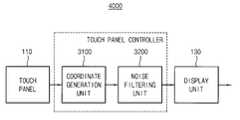
도 13의 본 발명의 일 실시예에 따른 터치 스크린에서의 노이즈 제거 장치(3000)는 터치 패널 컨트롤러에 포함된다.The
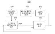
도 13을 참조하면, 본 발명의 일 실시예에 따른 터치 스크린에서의 노이즈 제거 장치(3000)는 좌표 생성부(coordinate generation unit)(3100) 및 노이즈 필터링부(noise filtering unit)(3200)를 포함한다.Referring to FIG. 13, an
좌표 생성부(3100)는 터치 스크린상에서의 사용자의 연속적인 터치 동작에 따라 입력 좌표들을 생성한다. 터치 스크린상에서 사용자가 터치를 유지한 상태에서 연속적으로 문자, 그림 등의 이미지를 입력하는 경우, 좌표 생성부(3100)는 일정 주기에 따라 주기적으로 사용자의 터치 위치에 따른 상기 입력 좌표들을 생성할 수 있다.The coordinate
노이즈 필터링부(3200)는 좌표 생성부(3100)로부터 제공되는 입력 좌표들을 수신하여, 상기 터치 동작의 이동 방향 및 이동 속도에 따라 가변적으로 설정되는 유효 영역에 기초하여 상기 입력 좌표들을 필터링하여 최종 좌표들을 생성한다. 노이즈 필터링부(3200)는 상기 유효 영역에 기초하여 상기 입력 좌표들을 선택적으로 제거함으로써 최종 좌표들을 생성할 수 있다. 상기 최종 좌표들은 터치 스크린에 의해 사용자의 터치 위치로 최종적으로 결정된 좌표들을 나타낸다.The
좌표 생성부(3100)는 좌표 검출부(3110) 및 좌표 보정부(3120)를 포함할 수 있다.The coordinate
좌표 검출부(3110)는 상기 터치 스크린상에서의 사용자의 터치 위치를 검출하여 현재 검출 좌표를 생성할 수 있다.The coordinate
좌표 보정부(3120)는 좌표 검출부(3110)로부터 제공되는 상기 현재 검출 좌표를 수신하여, 상기 현재 검출 좌표가 직전 최종 좌표를 중심으로 하는 보정 영역에 포함되는지 여부에 기초하여 현재 입력 좌표를 결정할 수 있다.The coordinate
상기 직전 최종 좌표는 상기 최종 좌표들을 생성하는 과정에 있어서 이미 생성된 상기 최종 좌표들 중에서 바로 직전에 최종 좌표로 결정되었던 좌표를 나타낸다.The last final coordinate indicates a coordinate that was determined as the last coordinate immediately before the last among the final coordinates already generated in the process of generating the final coordinates.
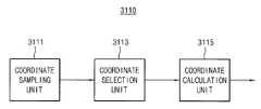
도 14는 도 13의 좌표 검출부(3110)의 일 예를 나타내는 블록도이다.FIG. 14 is a block diagram illustrating an example of the coordinate
도 14를 참조하면, 좌표 검출부(3110)는 좌표 샘플링부(coordinate sampling unit)(3111), 좌표 선택부(coordinate selection unit)(3113) 및 좌표 계산부(coordinate calculation unit)(3115)를 포함할 수 있다.Referring to FIG. 14, the coordinate
좌표 샘플링부(3111)는 상기 터치 스크린상에서의 사용자의 터치 위치를 n(n은 양의 정수)회 샘플링하여 n개의 좌표 샘플들을 생성할 수 있다. 상기 설명한 바와 같이, 터치 스크린상에서 사용자가 터치를 유지한 상태에서 연속적으로 문자, 그림 등의 이미지를 입력하는 경우, 주기적으로 사용자의 터치 위치에 따른 상기 입력 좌표들을 생성할 수 있다. 상기 입력 좌표들 각각을 생성하기 위해, 터치 스크린상에서의 사용자의 터치 위치를 매 주기마다 n회 샘플링하여 생성된 상기 n개의 좌표 샘플들을 사용할 수 있다.The coordinate
좌표 선택부(3113)는 좌표 샘플링부(3111)로부터 제공되는 상기 n개의 좌표 샘플들을 수신하여, 상기 n개의 좌표 샘플들을 구성하는 n개의 제1 방향 좌표들 및 n개의 제2 방향 좌표들 중에서 각각 k(k는 n이하의 양의 정수)개의 제1 방향 좌표들 및 k개의 제2 방향 좌표들을 선택할 수 있다. 구체적인 동작에 있어서, 좌표 선택부(3113)는 상기 n개의 제1 방향 좌표들 및 n개의 제2 방향 좌표들을 각각 올림차순 또는 내림차순으로 소팅하고, 상기 소팅된 n개의 제1 방향 좌표들 및 n개의 제2 방향 좌표들 중에서 각각 중간 값에 해당하는 상기 k개의 제1 방향 좌표들 및 k개의 제2 방향 좌표들을 선택할 수 있다.The coordinate selecting
좌표 계산부(3115)는 좌표 선택부(3113)로부터 제공되는 상기 k개의 제1 방향 좌표들 및 k개의 제2 방향 좌표들을 수신하여, 상기 k개의 제1 방향 좌표들의 가중평균값을 상기 현재 검출 좌표의 제1 방향 좌표로 결정하고, 상기 k개의 제2 방향 좌표들의 가중평균값을 상기 현재 검출 좌표의 제2 방향 좌표로 결정할 수 있다.The coordinate
상기 제1 방향은 x축 방향으로 정의할 수 있고, 상기 제2 방향은 y축 방향으로 정의할 수 있으며, 이 때, 상기 제1 방향 좌표는 x좌표로 정의할 수 있고, 상기 제2 방향 좌표는 y좌표로 정의할 수 있다. 이하, 상기 제1 방향은 x축 방향으로 정의하고, 상기 제2 방향은 y축 방향으로 정의하여 설명한다.The first direction may be defined in the x-axis direction, the second direction may be defined in the y-axis direction, and in this case, the first direction coordinate may be defined in x-coordinate and the second direction coordinates. Can be defined by y coordinate. Hereinafter, the first direction is defined in the x-axis direction, and the second direction is defined in the y-axis direction.
예를 들어, n=8, k=4인 경우에 대한 도 14의 좌표 검출부(3110)의 동작에 대해 설명하면 아래와 같다.For example, the operation of the coordinate
좌표 샘플링부(3111)는 8개의 좌표 샘플들((x0, y0),......, (x7, y7))을 생성하고, 좌표 선택부(3113)는 x0 내지 x7을 올림차순 또는 내림차순으로 소팅하여 중간 값에 해당하는 4개의 x좌표인 세 번째 내지 여섯 번째 x좌표(xa1, xa2, xa3, xa4)를 선택하고, y0 내지 y7을 올림차순 또는 내림차순으로 소팅하여 중간 값에 해당하는 4개의 y좌표(yb1, yb2, yb3, yb4)를 선택한다. 좌표 계산부(3115)는 아래의 [수학식 7]에 의해 xa1, xa2, xa3 및 xa4의 가중평균값을 상기 현재 검출 좌표의 x좌표로 결정하고, [수학식 8]에 의해 yb1, yb2, yb3 및 yb4의 가중평균값을 상기 현재 검출 좌표의 y좌표로 결정한다.The coordinate
= (xa1 + 3*xa2 + 3*xa3 + xa4) / 8= (xa1 + 3 * xa2 + 3 * xa3 + xa4 ) / 8
= (yb1 + 3*yb2 + 3*yb3 + yb4) / 8= (yb1 + 3 * yb2 + 3 * yb3 + yb4 ) / 8
여기서, xC 및 yC는 각각 상기 현재 검출 좌표의 x좌표 및 y좌표를 나타낸다.Here, xC and yC represent the x coordinate and the y coordinate of the current detection coordinate, respectively.
상기 [수학식 7] 및 [수학식 8]에서는 x0 내지 x7을 올림차순 또는 내림차순으로 소팅하여 네 번째 및 다섯 번째의 x좌표(xa2, xa3) 및 y0 내지 y7을 올림차순 또는 내림차순으로 소팅하여 네 번째 및 다섯 번째의 y좌표(yb2, yb3)에 대해서는 3의 가중치를 가하고, x0 내지 x7을 올림차순 또는 내림차순으로 소팅하여 세 번째 및 여섯 번째의 x좌표(xa1, xa4) 및 y0 내지 y7을 올림차순 또는 내림차순으로 소팅하여 세 번째 및 여섯 번째의 y좌표(yb1, yb4)에 대해서는 1의 가중치를 가함으로써 시프트(shift) 연산을 통해 빠르게 상기 현재 검출 좌표를 생성할 수 있다.In Equations 7 and 8, x0 to x7 are sorted in ascending or descending order, so that the fourth and fifth x coordinates (xa2 , xa3 ) and y0 to y7 are in ascending or descending order. Sorting with the fourth and fifth y-coordinates (yb2 , yb3 ), weighting 3, and sorting x0 to x7 in ascending or descending order, so that the third and sixth x-coordinates (xa1 , xa4 ) and y0 to y7 sorted in ascending or descending order to detect the current quickly through a shift operation by adding a weight of 1 to the third and sixth y-coordinates (yb1 , yb4 ) You can create coordinates.
실시예에 따라서 좌표 검출부(3110)는 가중치를 상기와 다르게 가하여 상기 현재 검출 좌표를 생성할 수도 있다.According to an exemplary embodiment, the coordinate
도 14를 참조하여 상기 설명한 바와 같이, 좌표 검출부(3110)는 n개의 좌표를 샘플링하고, 상기 n개의 좌표 샘플들을 소팅하여 중간 값에 해당하는 좌표 샘플들을 가중평균함으로써 상기 현재 검출 좌표를 생성하기 때문에, 사용자의 실제 터 치 위치를 정확하게 검출할 수 있고, 상기 가중평균은 시프트 연산을 통해 수행되므로 빠른 속도로 상기 현재 검출 좌표를 생성할 수 있다.As described above with reference to FIG. 14, the coordinate
도 15는 도 13의 좌표 보정부(3120)의 일 예를 나타내는 블록도이다.FIG. 15 is a block diagram illustrating an example of the coordinate
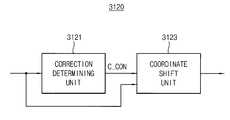
도 15를 참조하면, 좌표 보정부(3120)는 보정 판단부(correction determining unit)(3121) 및 좌표 이동부(coordinate shift unit)(3123)를 포함할 수 있다.Referring to FIG. 15, the coordinate
보정 판단부(3121)는 좌표 검출부(3110)로부터 제공되는 상기 현재 검출 좌표를 수신하여, 상기 현재 검출 좌표가 상기 보정 영역에 포함되는지 여부를 판단하여 보정 제어 신호(C_CON)를 생성할 수 있다.The
도 5a를 참조하여 보정 판단부(3121)의 동작에 대해 설명한다.The operation of the
도 5a에서 좌표(P1)는 상기 직전 최종 좌표를 나타내고, 좌표(C)는 상기 현재 검출 좌표를 나타낸다. 보정 판단부(3121)는 상기 직전 최종 좌표(P1)를 중심으로 하여 x축 방향으로 2a(a는 양의 정수), y축 방향으로 2b(b는 양의 정수)의 길이를 갖는 직사각형 영역(A)을 상기 보정 영역으로 설정할 수 있다.In FIG. 5A, coordinate P1 represents the last final coordinate, and coordinate C represents the current detection coordinate. The
예를 들면, x축 방향으로 480픽셀을 포함하고, y축 방향으로 800픽셀을 포함하는 터치 스크린의 경우, 보정 판단부(3121)는 상기 보정 영역(A)의 x축 방향의 길이는 64픽셀, 즉, a=32, y축 방향의 길이는 128픽셀, 즉, b=64로 설정할 수 있다.For example, in the case of a touch screen including 480 pixels in the x-axis direction and 800 pixels in the y-axis direction, the
보정 판단부(3121)는 아래의 [수학식 9]에 의해 상기 현재 검출 좌표(C)가 상기 보정 영역(A)에 포함되는지 여부를 판단할 수 있다.The
여기서, 상기 직전 최종 좌표(P1)의 좌표는 (x1, y1)이고, 상기 현재 검출 좌표(C)의 좌표는 (xC, yC)이다.Here, the coordinates of the immediately preceding final coordinate P1 are (x1 , y1 ), and the coordinates of the current detection coordinate C are (xC , yC ).
상기 [수학식 9]를 만족하는 경우, 보정 판단부(3121)는 제1 값을 갖는 상기 보정 제어 신호(C_CON)를 생성하고, 상기 [수학식 9]를 만족하지 않는 경우, 보정 판단부(3121)는 제2 값을 갖는 상기 보정 제어 신호(C_CON)를 생성할 수 있다.When the equation (9) is satisfied, the
좌표 이동부(3123)는 상기 보정 제어 신호(C_CON) 및 상기 현재 검출 좌표(xC, yC)를 수신하여, 상기 현재 입력 좌표를 생성할 수 있다.The coordinate moving
보다 상세하게는, 좌표 이동부(3123)는, 상기 보정 제어 신호(C_CON)가 상기 제1 값을 갖는 경우, 상기 현재 검출 좌표 및 상기 직전 최종 좌표 사이의 거리에 기초하여 상기 현재 검출 좌표 및 상기 직전 최종 좌표 사이의 거리가 감소하도록 상기 현재 검출 좌표를 이동하여 상기 이동된 현재 검출 좌표를 상기 현재 입력 좌표로 결정하고, 상기 보정 제어 신호(C_CON)가 상기 제2 값을 갖는 경우, 상기 현재 검출 좌표를 이동시키지 않고 상기 현재 검출 좌표를 상기 현재 입력 좌표로 결정할 수 있다.In more detail, when the correction control signal C_CON has the first value, the coordinate moving
도 5b를 참조하여 상기 보정 제어 신호(C_CON)가 상기 제1 값을 갖는 경우에 대한 좌표 이동부(3123)의 동작에 대해 설명한다.An operation of the coordinate moving
도 5b에서 좌표(P1)는 상기 직전 최종 좌표를 나타내고, 좌표(C)는 상기 현 재 검출 좌표를 나타내고, 좌표(S)는 상기 이동된 현재 검출 좌표를 나타내는 것으로서 상기 이동된 현재 검출 좌표는 상기 현재 입력 좌표(S)로 결정된다.In FIG. 5B, coordinate P1 represents the last final coordinate, coordinate C represents the current detection coordinate, and coordinate S represents the moved current detection coordinate, and the moved current detection coordinate is the above. The current input coordinate S is determined.
좌표 이동부(3123)는 상기 보정 제어 신호(C_CON)가 상기 제1 값을 갖는 경우, 도 5b에 도시된 바와 같이, 상기 현재 검출 좌표(C) 및 상기 직전 최종 좌표(P1) 사이의 거리에 기초하여 상기 현재 검출 좌표(C) 및 상기 직전 최종 좌표(P1) 사이의 거리가 감소하도록 상기 현재 검출 좌표(C)를 이동하여 상기 이동된 현재 검출 좌표를 상기 현재 입력 좌표(S)로 결정할 수 있다.When the correction control signal C_CON has the first value, the coordinate moving
좌표 이동부(3123)는 아래의 [수학식 10]9] 및 [수학식 11]에 의해 상기 현재 입력 좌표(S)를 결정할 수 있다.The coordinate moving
여기서, 상기 직전 최종 좌표(P1)의 좌표는 (x1, y1)이고, 상기 현재 검출 좌표(C)의 좌표는 (xC, yC)이고, 상기 현재 입력 좌표(S)의 좌표는 (xS, yS)이다.Here, the coordinates of the immediately preceding final coordinates P1 are (x1 , y1 ), the coordinates of the current detection coordinates C are (xC , yC ), and the coordinates of the current input coordinates S are (xS , yS ).
즉, 좌표 이동부(3123)는 상기 현재 입력 좌표(S)가 상기 직전 최종 좌표(P1)로부터 x축 방향으로 떨어진 거리(|xS-x1|)에 대한 상기 현재 검출 좌표(C)가 상기 직전 최종 좌표(P1)로부터 x축 방향으로 떨어진 거리(|xC-x1|)의 비율은, 상기 현재 검출 좌표(C)가 상기 직전 최종 좌표(P1)로부터 x축 방향으로 떨어진 거리(|xC-x1|)에 대한 상기 직전 최종 좌표(P1)로부터 x축 방향으로 상기 보정 영역(A)의 경계까지의 거리(a)의 비율과 동일하도록 상기 현재 입력 좌표(S)의 x좌표를 결정할 수 있다.That is, the coordinate moving
마찬가지로, 좌표 이동부(3123)는 상기 현재 입력 좌표(S)가 직전 입력 좌표(P1)로부터 y축 방향으로 떨어진 거리(|yS-y1|)에 대한 터치 좌표(C)가 직전 입력 좌표(P1)로부터 y축 방향으로 떨어진 거리(|yC-y1|)의 비율은, 터치 좌표(C)가 직전 입력 좌표(P1)로부터 y축 방향으로 떨어진 거리(|yC-y1|)에 대한 직전 입력 좌표(P1)로부터 y축 방향으로 일정 영역(A)의 경계까지의 거리(b)의 비율과 동일하도록 상기 현재 입력 좌표(S)의 y좌표를 결정할 수 있다.Similarly, the coordinate moving
이상, 좌표 보정부(3120)는, 도 5a 및 도 5b를 참조하여 설명한 바와 같이, 상기 보정 영역을 직사각형의 영역으로 설정한 경우를 예로 들어 설명하였으나, 실시예에 따라서 상기 보정 영역을 상기 직전 최종 좌표를 중심으로 하는 원형의 영역 또는 타원형의 영역 등 다른 형상의 영역으로 설정할 수도 있다.As described above with reference to FIGS. 5A and 5B, the coordinate
도 13 내지 15를 참조하여 설명한 바와 같이, 도 13에 도시된 본 발명의 일 실시예에 따른 터치 스크린에서의 노이즈 제거 장치(3000)는, 상기 현재 검출 좌표와 상기 직전 최종 좌표와의 위치 관계에 따라 선택적으로 상기 현재 검출 좌표 및 상기 직전 최종 좌표 사이의 거리에 기초하여 상기 현재 검출 좌표 및 상기 직전 최종 좌표 사이의 거리가 감소하도록 상기 현재 검출 좌표를 이동하여 상기 이동된 현재 검출 좌표를 상기 현재 입력 좌표로 결정함으로써, 터치 스크린의 속도를 크게 저하시키지 않으면서 터치한 좌표 검출시 발생하는 노이즈로 인한 미세한 떨림 현상을 효과적으로 제거할 수 있다.As described with reference to FIGS. 13 to 15, the apparatus for removing noise of a
도 16은 도 13의 노이즈 필터링부(3200)의 일 예를 나타내는 블록도이다.FIG. 16 is a block diagram illustrating an example of the
도 16을 참조하면, 노이즈 필터링부(3200)는 버퍼부(buffer unit)(3210), 모션 벡터 결정부(motion vector determining unit)(3220), 유효 영역 설정부(valid area setting unit)(3230), 필터링 판단부(filtering determining unit)(3240) 및 스위치부(3250)를 포함할 수 있다.Referring to FIG. 16, the
버퍼부(3210)는 스위치부(3250)로부터 상기 최종 좌표들을 수신하여, 상기 최종 좌표들을 저장하고, 상기 저장된 최종 좌표들을 제공할 수 있다. 버퍼부(3210)는 상기 최종 좌표들을 저장하기 위한 메모리부를 포함할 수 있다.The
모션 벡터 결정부(3220)는 버퍼부(3210)로부터 이전 최종 좌표들을 수신하여, 상기 이전 최종 좌표들에 기초하여 사용자의 움직임을 나타내는 모션 벡터를 결정할 수 있다.The
도 8을 참조하여 모션 벡터 결정부(3220)의 동작에 대해 설명한다.An operation of the
도 8에서 좌표(P1)는 상기 최종 좌표들을 생성하는 과정에 있어서 이미 생성된 상기 최종 좌표들 중에서 바로 직전에 최종 좌표로 결정되었던 직전 최종 좌표를 나타내고, 좌표(P2)는 상기 직전 최종 좌표가 결정되기 직전에 최종 좌표로 결정되었던 좌표, 즉, 두 시점 이전의 최종 좌표를 나타내고, 좌표(P3)는 세 시점 이전의 최종 좌표를 나타내고, 좌표(P4)는 네 시점 이전의 최종 좌표를 나타내고, 좌 표(P5)는 다섯 시점 이전의 최종 좌표를 나타낸다.In FIG. 8, the coordinate P1 represents the last final coordinate determined immediately before the last coordinate among the final coordinates already generated in the process of generating the final coordinates, and the coordinate P2 is determined by the last final coordinate. Coordinates that were determined as final coordinates immediately before, i.e., the last coordinates before two views, coordinate P3 represents the final coordinates before three views, coordinate P4 represents the final coordinates before four views, and Table P5 shows the final coordinates before five time points.
도 8을 참조하면, 모션 벡터 결정부(3220)는 상기 두 시점 이전의 최종 좌표(P2)를 시점으로 하고, 상기 직전 최종 좌표(P1)를 종점으로 하는 벡터(M)를 상기 모션 벡터로 결정할 수 있다.Referring to FIG. 8, the
상기 모션 벡터는 터치 스크린상에서의 사용자의 연속적인 터치 동작에 있어서, 터치 위치가 터치 스크린상에서 이동하는 방향 및 속도를 나타낸다.The motion vector represents the direction and speed at which the touch position moves on the touch screen in the user's continuous touch operation on the touch screen.
다시 도 16을 참조하면, 유효 영역 설정부(3230)는 모션 벡터 결정부(3220)로부터 수신한 상기 모션 벡터에 기초하여 상기 유효 영역을 설정할 수 있다.Referring back to FIG. 16, the valid
필터링 판단부(3240)는 상기 현재 입력 좌표가 상기 유효 영역에 포함되는지 여부를 판단하여 필터링 제어 신호(F_CON)를 생성할 수 있다.The
도 9 내지 도 11을 참조하여 유효 영역 설정부(3230) 및 필터링 판단부(3240)의 동작에 대해 설명한다.An operation of the effective
도 9 내지 도 11에서 좌표(P1)는 상기 직전 최종 좌표를 나타내고, 좌표(P2)는 상기 두 시점 이전의 최종 좌표를 나타내고, 좌표(P3)는 세 시점 이전의 최종 좌표를 나타내고, 좌표(P4)는 네 시점 이전의 최종 좌표를 나타내고, 좌표(P5)는 다섯 시점 이전의 최종 좌표를 나타낸다.In FIG. 9 to FIG. 11, the coordinate P1 represents the last final coordinate, the coordinate P2 represents the final coordinate before the two viewpoints, the coordinate P3 represents the final coordinate before three viewpoints, and the coordinate P4. ) Denotes the final coordinates before four viewpoints, and coordinate P5 denotes the final coordinates before five viewpoints.
도 9를 참조하면, 상기 직전 최종 좌표(P1)를 시점으로 하는 상기 모션 벡터(M)의 종점(O)을 중심으로 하고, 상기 모션 벡터의 크기(|M|)를 반지름으로 하는 원형의 영역(V)을 상기 유효 영역으로 고려할 수 있다.Referring to FIG. 9, a circular region centered on an end point O of the motion vector M having the last final coordinate P1 as a starting point and a radius of the size of the motion vector | M | (V) can be considered as the effective area.
그러나 사용자가 한 지점에서 터치한 상태에서 일정 시간 동안 정지한 후 이 미지를 입력하기 위해 이동을 하는 경우, 상기 직전 최종 좌표(P1) 및 상기 두 시점 이전의 최종 좌표(P2)는 서로 동일하게 되어 상기 모션 벡터(M)는 영벡터가 된다. 이러한 경우 상기 유효 영역(V)의 면적이 0이 된다는 문제점이 있다.However, when the user stops for a predetermined time while moving at a point and moves to input an image, the last final coordinate P1 and the last previous coordinate P2 before the two viewpoints become equal to each other. The motion vector M becomes a zero vector. In this case, there is a problem that the area of the effective area V becomes zero.
따라서 유효 영역 설정부(3230)는 도 10에 도시된 바에 따라 상기 유효 영역을 설정할 수 있다.Accordingly, the effective
도 10에서 좌표(S)는 상기 현재 입력 좌표를 나타낸다.Coordinate S in FIG. 10 represents the current input coordinate.
도 10을 참조하면, 유효 영역 설정부(3230)는 상기 직전 최종 좌표(P1)를 시점으로 하는 상기 모션 벡터(M)의 종점(O)을 중심으로 하고, 상기 모션 벡터의 크기(|M|)에 일정 상수(e)(e는 양의 정수)를 더한 값을 반지름으로 하는 원형의 영역(V')을 상기 유효 영역으로 설정할 수 있다.Referring to FIG. 10, the effective
이 경우, 필터링 판단부(3240)는 상기 유효 영역(V')의 중점(O) 및 상기 현재 입력 좌표(S) 사이의 유클리디언 거리가 상기 모션 벡터의 크기(|M|)에 일정 상수(e)를 더한 값보다 큰지 여부를 결정함으로써 상기 현재 입력 좌표(S)가 상기 유효 영역(V')에 포함되는지 여부를 판단할 수 있다. 필터링 판단부(3240)는 상기 판단 결과, 상기 유효 영역(V')의 중점(O) 및 상기 현재 입력 좌표(S) 사이의 유클리디언 거리가 상기 모션 벡터의 크기(|M|)에 일정 상수(e)를 더한 값보다 작거나 같은 경우, 제1 값을 갖는 상기 필터링 제어 신호(F_CON)를 생성하고, 상기 유효 영역(V')의 중점(O) 및 상기 현재 입력 좌표(S) 사이의 유클리디언 거리가 상기 모션 벡터의 크기(|M|)에 일정 상수(e)를 더한 값보다 큰 경우, 상기 제2 값을 갖는 필터링 제어 신호(F_CON)를 생성할 수 있다.In this case, the
한편, 유효 영역 설정부(3230)가 상기 유효 영역을 도 10에 도시된 바와 같이 원형의 영역으로 설정하는 경우, 필터링 판단부(3240)가 상기 유효 영역(V')의 중점(O) 및 상기 현재 입력 좌표(S) 사이의 유클리디언 거리를 구하는 데에 많은 시간이 소요되어 터치 스크린의 동작 속도가 저하될 가능성이 있으므로, 터치 스크린의 동작 속도를 보다 증가시키기 위해 유효 영역 설정부(3230)는 도 11에 도시된 바에 따라 상기 유효 영역을 설정할 수도 있다.On the other hand, when the effective
도 11을 참조하면, 유효 영역 설정부(3230)는 상기 직전 최종 좌표(P1)를 시점으로 하는 상기 모션 벡터(M)의 종점(O)을 중심으로 하고, 상기 모션 벡터의 크기(|M|)에 일정 상수(e)를 더한 값의 두 배를 대각선의 길이로 갖는 정사각형의 영역(V'')을 상기 유효 영역으로 설정할 수 있다.Referring to FIG. 11, the effective
이 경우, 필터링 판단부(3240)는 상기 유효 영역(V'')의 중점(O) 및 상기 현재 입력 좌표(S) 사이의 맨하탄 거리가 상기 유효 영역(V'')의 꼭지점과 상기 유효 영역의 중점(O) 사이의 맨하탄 거리보다 큰지 여부를 결정함으로써 상기 현재 입력 좌표(S)가 상기 유효 영역(V'')에 포함되는지 여부를 판단할 수 있다.In this case, the
필터링 판단부(3240)는 상기 판단 결과, 상기 유효 영역(V'')의 중점(O) 및 상기 현재 입력 좌표(S) 사이의 맨하탄 거리가 상기 유효 영역(V'')의 꼭지점과 상기 유효 영역의 중점(O) 사이의 맨하탄 거리보다 작거나 같은 경우, 제1 값을 갖는 상기 필터링 제어 신호(F_CON)를 생성하고, 상기 유효 영역(V'')의 중점(O) 및 상기 현재 입력 좌표(S) 사이의 맨하탄 거리가 상기 유효 영역(V'')의 꼭지점과 상기 유효 영역의 중점(O) 사이의 맨하탄 거리보다 큰 경우, 상기 제2 값을 갖는 필터링 제어 신호(F_CON)를 생성할 수 있다.As a result of the determination, the
즉, 아래의 [수학식 12]를 만족하는 경우, 필터링 판단부(3240)는 상기 제1 값을 갖는 상기 필터링 제어 신호(F_CON)를 생성하고, 아래의 [수학식 12]를 만족하지 않는 경우, 필터링 판단부(3240)는 상기 제2 값을 갖는 상기 필터링 제어 신호(F_CON)를 생성할 수 있다.That is, when the following Equation 12 is satisfied, the
여기서, 상기 유효 영역의 중심의 좌표는 (xO, yO)이고, 상기 현재 입력 좌표는 (xS, yS)이다.Here, the coordinate of the center of the effective area is (xO , yO ), and the current input coordinate is (xS , yS ).
다시 도 16을 참조하면, 스위치부(3250)는 상기 필터링 제어 신호(F_CON) 및 상기 현재 입력 좌표를 수신하여 현재 최종 좌표를 생성한다.Referring back to FIG. 16, the
보다 상세하게는, 스위치부(3250)는 상기 필터링 제어 신호(F_CON)가 상기 제1 값을 갖는 경우, 상기 현재 입력 좌표를 현재 최종 좌표로 생성하고, 상기 필터링 제어 신호(F_CON)가 상기 제2 값을 갖는 경우, 상기 현재 입력 좌표를 노이즈에 의한 좌표로 결정하여 상기 현재 입력 좌표를 제거하고 상기 현재 최종 좌표를 생성하지 않을 수 있다.In more detail, when the filtering control signal F_CON has the first value, the
일반적으로 터치 스크린상에서 사용자가 연속적으로 문자, 그림 등의 이미지를 입력하는 경우, 사용자의 움직임의 이동 방향 및 이동 속도에 따라 상기 현재 입력 좌표가 위치할 수 있는 영역이 결정된다. 다시 말하면, 사용자가 터치 스크린 상에서 연속적인 이미지를 그리는 경우, 사용자의 움직임이 이동하던 방향, 즉, 상기 모션 벡터 방향의 영역에 상기 현재 입력 좌표가 위치할 가능성이 높고, 또한 사용자의 움직임의 이동 속도가 빠를수록, 즉, 상기 모션 벡터의 크기가 클수록 상기 현재 입력 좌표가 위치할 수 있는 영역이 넓어진다.In general, when a user continuously inputs an image such as a text or a picture on the touch screen, an area in which the current input coordinate may be located is determined according to the moving direction and the moving speed of the user's movement. In other words, when the user draws a continuous image on the touch screen, it is highly likely that the current input coordinates are located in the direction in which the user's movement is moving, that is, in the region of the motion vector direction, and the movement speed of the user's movement. The faster, that is, the larger the size of the motion vector, the wider the area where the current input coordinate can be located.
따라서 도 13 및 16을 참조하여 설명한 바와 같이, 도 13에 도시된 본 발명의 일 실시예에 따른 터치 스크린에서의 노이즈 제거 장치(3000)는, 상기 이전 최종 좌표들에 기초하여 사용자의 움직임을 나타내는 상기 모션 벡터를 결정하고, 상기 모션 벡터에 기초하여 상기 유효 영역을 설정하여, 사용자의 움직임에 따라 상기 현재 입력 좌표가 위치할 수 있는 상기 유효 영역의 위치 및 크기를 상이하게 설정함으로써, 연속적인 이미지를 입력하는 경우 입력의 시점 및 종점에서 주로 발생하는 비정상적으로 튀는 현상, 즉, 입력된 지점과 무관한 지점의 좌표가 터치된 것으로 검출되어 이미지가 왜곡되는 현상을 효과적으로 제거할 수 있다.Accordingly, as described with reference to FIGS. 13 and 16, the
도 17은 본 발명의 일 실시예에 따른 터치 스크린을 구비한 디스플레이 장치를 나타내는 블록도이다.17 is a block diagram illustrating a display device having a touch screen according to an embodiment of the present invention.
도 17을 참조하면, 터치 스크린을 구비한 디스플레이 장치(4000)는 터치 패널(110), 좌표 생성부(3100) 및 노이즈 필터링부(3200)를 포함하는 터치 패널 컨트롤러, 및 디스플레이부(130)를 포함한다.Referring to FIG. 17, a
터치 패널(110)은 디스플레이부(130) 위에 배치되고, 사용자의 터치 위치에 상응하는 터치 신호들을 생성한다.The
좌표 생성부(3100)는 상기 터치 신호들에 기초하여 터치 스크린상에서의 사 용자의 연속적인 터치 동작에 따라 입력 좌표들을 생성한다. 터치 스크린상에서 사용자가 터치를 유지한 상태에서 연속적으로 문자, 그림 등의 이미지를 입력하는 경우, 좌표 생성부(3100)는 일정 주기에 따라 주기적으로 사용자의 터치 위치에 따른 상기 입력 좌표들을 생성할 수 있다.The coordinate
도 13 내지 도 15와 관련하여 좌표 생성부(3100)의 구성 및 동작에 대해 상세히 설명하였으므로, 중복을 피하기 위해 여기서는 상세한 설명은 생략한다.Since the configuration and operation of the coordinate
노이즈 필터링부(3200)는 좌표 생성부(3100)로부터 제공되는 입력 좌표들을 수신하여, 상기 터치 동작의 이동 방향 및 이동 속도에 따라 가변적으로 설정되는 유효 영역에 기초하여 상기 입력 좌표들을 필터링하여 최종 좌표들을 생성한다. 노이즈 필터링부(3200)는 상기 유효 영역에 기초하여 상기 입력 좌표들을 선택적으로 제거함으로써 최종 좌표들을 생성할 수 있다. 상기 최종 좌표들은 터치 스크린에 의해 사용자의 터치 위치로 최종적으로 결정된 좌표들을 나타낸다.The
도 13 및 도 16과 관련하여 노이즈 필터링부(3200)의 구성 및 동작에 대해 상세히 설명하였으므로, 중복을 피하기 위해 여기서는 상세한 설명은 생략한다.Since the configuration and operation of the
디스플레이부(130)는 노이즈 필터링부(3200)로부터 수신한 상기 최종 좌표들에 기초하여 상기 사용자의 연속적인 터치 동작에 따른 이미지를 출력할 수 있다. 이 때, 상기 현재 최종 좌표가 상기 사용자의 연속적인 터치 동작 중에 최초로 생성된 최종 좌표인 경우, 디스플레이 장치(4000)는 상기 현재 최종 좌표에 해당하는 화면상의 위치에 점을 디스플레이하고, 상기 현재 최종 좌표가 상기 최초로 생성된 최종 좌표 이후에 생성된 최종 좌표인 경우, 디스플레이 장치(4000)는 상기 현재 최종 좌표와 상기 직전 최종 좌표를 연결하는 직선을 디스플레이할 수 있다.The
도 17의 터치 스크린을 구비한 디스플레이 장치(4000)는 노트북, 휴대폰, PDA(Personal Digital Assistant), MP3 플레이어 등과 같이 터치 스크린 장치를 구비하는 임의의 디스플레이 장치일 수 있다.The
또한, 디스플레이 장치(4000)가 구비하는 터치 스크린은 감압식 터치 스크린 및 정전식 터치 스크린을 포함하는 모든 종류의 터치 스크린일 수 있다.In addition, the touch screen included in the
본 발명은 감압식 터치 스크린 및 정전식 터치 스크린을 포함하는 모든 종류의 터치 스크린에서, 터치한 좌표 검출시 발생하는 노이즈를 효과적으로 제거하도록 유용하게 이용될 수 있다.The present invention can be usefully used in all kinds of touch screens including a pressure sensitive touch screen and a capacitive touch screen to effectively remove noise generated when detecting touched coordinates.
또한 본 발명은 노트북, 휴대폰, PDA, MP3 플레이어 등과 같이 이미지를 출력할 수 있으면서 터치 스크린 장치를 구비하는 임의의 디스플레이 장치에서 터치한 좌표 검출시 발생하는 노이즈를 효과적으로 제거하여 사용자가 입력한 이미지를 정확하게 출력하도록 유용하게 이용될 수 있다.In addition, the present invention can accurately output the image input by the user by effectively removing the noise generated when the touch coordinates are detected in any display device having a touch screen device while being able to output the image, such as a laptop, mobile phone, PDA, MP3 player, etc. This can be useful for output.
상기에서는 본 발명이 바람직한 실시예를 참조하여 설명하였지만, 해당 기술분야의 숙련된 당업자는 하기의 특허청구범위에 기재된 본 발명의 사상 및 영역으로부터 벗어나지 않는 범위 내에서 본 발명을 다양하게 수정 및 변경시킬 수 있음을 이해할 것이다.While the present invention has been described with reference to the preferred embodiments thereof, it will be apparent to those skilled in the art that various modifications and variations can be made in the present invention without departing from the spirit and scope of the invention as defined in the appended claims. It will be understood.
도 1은 터치 스크린을 구비한 디스플레이 장치를 나타내는 블록도이다.1 is a block diagram illustrating a display device having a touch screen.
도 2는 본 발명의 일 실시예에 따른 터치 스크린에서의 노이즈 제거 방법을 나타내는 순서도이다.2 is a flowchart illustrating a method of removing noise in a touch screen according to an embodiment of the present invention.
도 3a는 도 2의 입력 좌표들을 생성하는 단계의 일 예를 나타내는 순서도이다.3A is a flowchart illustrating an example of generating input coordinates of FIG. 2.
도 3b는 도 3a의 현재 검출 좌표를 생성하는 단계의 일 예를 나타내는 순서도이다.3B is a flowchart illustrating an example of generating a current detection coordinate of FIG. 3A.
도 4a는 사용자가 빠른 속도로 직선을 입력한 경우 발생할 수 있는 터치 스크린을 구비한 디스플레이 장치의 출력 결과의 일 예를 나타내는 도면이다.4A is a diagram illustrating an example of an output result of a display apparatus having a touch screen that may occur when a user inputs a straight line at a high speed.
도 4b는 사용자가 느린 속도로 직선을 입력한 경우 발생할 수 있는 터치 스크린을 구비한 디스플레이 장치의 출력 결과의 일 예를 나타내는 도면이다.4B is a diagram illustrating an example of an output result of a display apparatus having a touch screen that may occur when a user inputs a straight line at a slow speed.
도 5a는 도 3a의 현재 입력 좌표를 결정하는 단계를 설명하기 위한 도면이다.FIG. 5A is a diagram for describing an operation of determining a current input coordinate of FIG. 3A.
도 5b는 도 3a의 이동된 현재 검출 좌표를 현재 입력 좌표로 결정하는 단계를 설명하기 위한 도면이다.FIG. 5B is a diagram for describing a step of determining the moved current detection coordinate of FIG. 3A as the current input coordinate.
도 6a는 도 3a의 현재 입력 좌표를 결정하는 단계가 적용되지 않은 경우에 대한 터치 스크린을 구비한 디스플레이 장치의 출력 결과의 일 예를 나타내는 도면이다.FIG. 6A is a diagram illustrating an example of an output result of a display apparatus having a touch screen when the determining of the current input coordinates of FIG. 3A is not applied.
도 6b는 도 3a의 현재 입력 좌표를 결정하는 단계가 적용된 경우에 대한 터 치 스크린을 구비한 디스플레이 장치의 출력 결과의 일 예를 나타내는 도면이다.FIG. 6B is a diagram illustrating an example of an output result of a display apparatus having a touch screen when the step of determining the current input coordinate of FIG. 3A is applied.
도 7은 도 2의 최종 좌표들을 생성하는 단계의 일 예를 나타내는 순서도이다.FIG. 7 is a flowchart illustrating an example of generating final coordinates of FIG. 2.
도 8은 도 7의 모션 벡터를 결정하는 단계를 설명하기 위한 도면이다.FIG. 8 is a diagram for describing an operation of determining the motion vector of FIG. 7.
도 9 내지 도 11은 도 7의 유효 영역을 설정하는 단계를 설명하기 위한 도면이다.9 to 11 are diagrams for describing a step of setting an effective area of FIG. 7.
도 12는 본 발명의 일 실시예에 따른 터치 스크린을 구비한 디스플레이 장치에서의 터치 동작 디스플레이 방법을 나타내는 순서도이다.12 is a flowchart illustrating a touch operation display method in a display device having a touch screen according to an embodiment of the present invention.
도 13은 본 발명의 일 실시예에 따른 터치 스크린에서의 노이즈 제거 장치를 나타내는 블록도이다.13 is a block diagram illustrating an apparatus for removing noise in a touch screen according to an embodiment of the present invention.
도 14는 도 13의 좌표 검출부의 일 예를 나타내는 블록도이다.14 is a block diagram illustrating an example of a coordinate detector of FIG. 13.
도 15는 도 13의 좌표 보정부의 일 예를 나타내는 블록도이다.FIG. 15 is a block diagram illustrating an example of a coordinate corrector of FIG. 13.
도 16은 도 13의 노이즈 필터링부의 일 예를 나타내는 블록도이다.16 is a block diagram illustrating an example of the noise filtering unit of FIG. 13.
도 17은 본 발명의 일 실시예에 따른 터치 스크린을 구비한 디스플레이 장치를 나타내는 블록도이다.17 is a block diagram illustrating a display device having a touch screen according to an embodiment of the present invention.
<도면의 주요부분에 대한 부호의 설명><Description of the symbols for the main parts of the drawings>
C: 현재 검출 좌표 S: 현재 입력 좌표C: current detection coordinate S: current input coordinate
P1: 직전 최종 좌표 P2: 두 시점 이전의 최종 좌표P1: last coordinate just before P2: last coordinate before two views
P3: 세 시점 이전의 최종 좌표 P4: 네 시점 이전의 최종 좌표P3: Final coordinates before three viewpoints P4: Final coordinates before four viewpoints
P5: 다섯 시점 이전의 최종 좌표 A: 보정 영역P5: Final coordinates before five time points A: Correction area
V, V', V'': 유효 영역 M: 모션 벡터V, V ', V' ': Effective Area M: Motion Vector
Claims (10)
Translated fromKoreanPriority Applications (2)
| Application Number | Priority Date | Filing Date | Title |
|---|---|---|---|
| KR1020090079887AKR20110022347A (en) | 2009-08-27 | 2009-08-27 | Method for removing noise on a touch screen and displaying a touch action on a display device having a touch screen |
| US12/846,969US8502791B2 (en) | 2009-08-27 | 2010-07-30 | Methods of processing data in touch screen display device and methods of displaying image using the same |
Applications Claiming Priority (1)
| Application Number | Priority Date | Filing Date | Title |
|---|---|---|---|
| KR1020090079887AKR20110022347A (en) | 2009-08-27 | 2009-08-27 | Method for removing noise on a touch screen and displaying a touch action on a display device having a touch screen |
Publications (1)
| Publication Number | Publication Date |
|---|---|
| KR20110022347Atrue KR20110022347A (en) | 2011-03-07 |
Family
ID=43624119
Family Applications (1)
| Application Number | Title | Priority Date | Filing Date |
|---|---|---|---|
| KR1020090079887AWithdrawnKR20110022347A (en) | 2009-08-27 | 2009-08-27 | Method for removing noise on a touch screen and displaying a touch action on a display device having a touch screen |
Country Status (2)
| Country | Link |
|---|---|
| US (1) | US8502791B2 (en) |
| KR (1) | KR20110022347A (en) |
Cited By (9)
| Publication number | Priority date | Publication date | Assignee | Title |
|---|---|---|---|---|
| KR20140037666A (en)* | 2012-09-19 | 2014-03-27 | 엘지디스플레이 주식회사 | Touch sensing method and apparatus having jitter cancel function |
| KR20140047269A (en)* | 2012-10-12 | 2014-04-22 | 에스케이플래닛 주식회사 | System and method for correcting touch error |
| KR20140057977A (en)* | 2012-11-05 | 2014-05-14 | 엘지디스플레이 주식회사 | Touch sensing system and method of controlling smoothing filter thereof |
| KR20140093326A (en)* | 2013-01-14 | 2014-07-28 | 엘지디스플레이 주식회사 | Electronic device having a touch sensor and driving method thereof |
| KR20150077782A (en)* | 2013-12-30 | 2015-07-08 | 엘지디스플레이 주식회사 | Touch algorithm of spiral search method |
| KR20190028963A (en)* | 2017-09-11 | 2019-03-20 | 주식회사 엣지아이앤디 | Apparatus of correcting touch input based on compensation hand vibration |
| KR20190043752A (en)* | 2017-10-19 | 2019-04-29 | 에스케이텔레콤 주식회사 | Touch recognizing method and apparatus |
| KR20190088454A (en)* | 2019-07-18 | 2019-07-26 | (주)컴버스테크 | Touch display apparatus of providing virtual touch |
| KR102207957B1 (en)* | 2020-05-15 | 2021-01-26 | 주식회사 에이치디텔레콤 | Electronic blackboard using multi-electronic pen |
Families Citing this family (27)
| Publication number | Priority date | Publication date | Assignee | Title |
|---|---|---|---|---|
| US8621380B2 (en) | 2010-01-06 | 2013-12-31 | Apple Inc. | Apparatus and method for conditionally enabling or disabling soft buttons |
| US9542091B2 (en) | 2010-06-04 | 2017-01-10 | Apple Inc. | Device, method, and graphical user interface for navigating through a user interface using a dynamic object selection indicator |
| EP2453343A3 (en) | 2010-09-24 | 2014-11-12 | BlackBerry Limited | Portable electronic device and method therefor |
| EP2434387B1 (en) | 2010-09-24 | 2020-01-08 | 2236008 Ontario Inc. | Portable electronic device and method therefor |
| KR20130005296A (en) | 2010-09-24 | 2013-01-15 | 큐엔엑스 소프트웨어 시스템즈 리미티드 | Portable electronic device and method of controlling same |
| US8587547B2 (en) | 2010-11-05 | 2013-11-19 | Apple Inc. | Device, method, and graphical user interface for manipulating soft keyboards |
| US9146673B2 (en) | 2010-11-05 | 2015-09-29 | Apple Inc. | Device, method, and graphical user interface for manipulating soft keyboards |
| US8842082B2 (en) | 2011-01-24 | 2014-09-23 | Apple Inc. | Device, method, and graphical user interface for navigating and annotating an electronic document |
| US9092132B2 (en) | 2011-01-24 | 2015-07-28 | Apple Inc. | Device, method, and graphical user interface with a dynamic gesture disambiguation threshold |
| CN102707821B (en)* | 2011-03-28 | 2015-04-22 | 深圳市汇顶科技股份有限公司 | Method and system for de-noising touch detection device |
| EP2717139B1 (en)* | 2011-05-30 | 2017-11-15 | Huawei Device (Dongguan) Co., Ltd. | Method, device and terminal for adjusting display region of page |
| TWI456448B (en)* | 2011-08-30 | 2014-10-11 | Pixart Imaging Inc | Touch system with track detecting function and method thereof |
| KR20130098459A (en) | 2012-02-28 | 2013-09-05 | 삼성전자주식회사 | Noise spectrum estimator and touch screen device including the same |
| US9703469B2 (en) | 2012-10-18 | 2017-07-11 | Dreamworks Animation Llc | Distinguishing between impulses and continuous drag operations on a touch-sensitive surface |
| US20150338960A1 (en)* | 2013-01-09 | 2015-11-26 | Sharp Kabushiki Kaisha | Touch panel system |
| CN103605424B (en)* | 2013-11-01 | 2016-09-14 | 中国人民解放军信息工程大学 | The viewpoints' integration method of space-air-ground integration situation expression engine and band inertia thereof |
| TWI502474B (en)* | 2013-11-28 | 2015-10-01 | Acer Inc | User interface operation method and electronic device |
| US9898162B2 (en) | 2014-05-30 | 2018-02-20 | Apple Inc. | Swiping functions for messaging applications |
| US9971500B2 (en) | 2014-06-01 | 2018-05-15 | Apple Inc. | Displaying options, assigning notification, ignoring messages, and simultaneous user interface displays in a messaging application |
| US20190310755A1 (en)* | 2016-03-22 | 2019-10-10 | Mitsubishi Electric Corporation | Coordinate correction apparatus |
| US10739972B2 (en) | 2016-06-10 | 2020-08-11 | Apple Inc. | Device, method, and graphical user interface for managing electronic communications |
| US10373747B2 (en)* | 2017-01-11 | 2019-08-06 | International Business Machines Corporation | Magnetic inductor stacks |
| US10593449B2 (en) | 2017-03-30 | 2020-03-17 | International Business Machines Corporation | Magnetic inductor with multiple magnetic layer thicknesses |
| US10607759B2 (en) | 2017-03-31 | 2020-03-31 | International Business Machines Corporation | Method of fabricating a laminated stack of magnetic inductor |
| US10597769B2 (en) | 2017-04-05 | 2020-03-24 | International Business Machines Corporation | Method of fabricating a magnetic stack arrangement of a laminated magnetic inductor |
| CN107193370A (en)* | 2017-04-27 | 2017-09-22 | 努比亚技术有限公司 | Realize the terminal and method of point vibration |
| US10347411B2 (en) | 2017-05-19 | 2019-07-09 | International Business Machines Corporation | Stress management scheme for fabricating thick magnetic films of an inductor yoke arrangement |
Family Cites Families (6)
| Publication number | Priority date | Publication date | Assignee | Title |
|---|---|---|---|---|
| JPH1011208A (en)* | 1996-06-24 | 1998-01-16 | Sharp Corp | Coordinate input device |
| JP2002287888A (en) | 2001-03-23 | 2002-10-04 | Sanyo Electric Co Ltd | Data processing device for touch panel |
| JP2004258837A (en) | 2003-02-25 | 2004-09-16 | Nippon Hoso Kyokai <Nhk> | Cursor operating device, its method and its program |
| US8164573B2 (en)* | 2003-11-26 | 2012-04-24 | Immersion Corporation | Systems and methods for adaptive interpretation of input from a touch-sensitive input device |
| JP2008192012A (en) | 2007-02-06 | 2008-08-21 | Sharp Corp | Coordinate input device, coordinate input method, control program, and computer-readable recording medium |
| KR101496844B1 (en)* | 2008-07-28 | 2015-02-27 | 삼성디스플레이 주식회사 | Touch screen display device and driving method of the same |
- 2009
- 2009-08-27KRKR1020090079887Apatent/KR20110022347A/ennot_activeWithdrawn
- 2010
- 2010-07-30USUS12/846,969patent/US8502791B2/enactiveActive
Cited By (10)
| Publication number | Priority date | Publication date | Assignee | Title |
|---|---|---|---|---|
| KR20140037666A (en)* | 2012-09-19 | 2014-03-27 | 엘지디스플레이 주식회사 | Touch sensing method and apparatus having jitter cancel function |
| KR20140047269A (en)* | 2012-10-12 | 2014-04-22 | 에스케이플래닛 주식회사 | System and method for correcting touch error |
| KR20140057977A (en)* | 2012-11-05 | 2014-05-14 | 엘지디스플레이 주식회사 | Touch sensing system and method of controlling smoothing filter thereof |
| KR20140093326A (en)* | 2013-01-14 | 2014-07-28 | 엘지디스플레이 주식회사 | Electronic device having a touch sensor and driving method thereof |
| KR20150077782A (en)* | 2013-12-30 | 2015-07-08 | 엘지디스플레이 주식회사 | Touch algorithm of spiral search method |
| KR20190028963A (en)* | 2017-09-11 | 2019-03-20 | 주식회사 엣지아이앤디 | Apparatus of correcting touch input based on compensation hand vibration |
| KR20190043752A (en)* | 2017-10-19 | 2019-04-29 | 에스케이텔레콤 주식회사 | Touch recognizing method and apparatus |
| KR20190088454A (en)* | 2019-07-18 | 2019-07-26 | (주)컴버스테크 | Touch display apparatus of providing virtual touch |
| KR102207957B1 (en)* | 2020-05-15 | 2021-01-26 | 주식회사 에이치디텔레콤 | Electronic blackboard using multi-electronic pen |
| WO2021230425A1 (en)* | 2020-05-15 | 2021-11-18 | 주식회사 에이치디텔레콤 | Electronic board using multiple electronic pens |
Also Published As
| Publication number | Publication date |
|---|---|
| US8502791B2 (en) | 2013-08-06 |
| US20110050607A1 (en) | 2011-03-03 |
Similar Documents
| Publication | Publication Date | Title |
|---|---|---|
| KR20110022347A (en) | Method for removing noise on a touch screen and displaying a touch action on a display device having a touch screen | |
| US9448667B2 (en) | Coordinate detecting device | |
| US8917257B2 (en) | Coordinate detecting device and coordinate detecting program | |
| US9639200B2 (en) | Touch detection circuit, touch detection method, and electronic apparatus | |
| US8692802B1 (en) | Method and apparatus for calculating coordinates with high noise immunity in touch applications | |
| JP5809516B2 (en) | TOUCH TYPE INPUT DEVICE, ITS CONTROLLER, CONTROL METHOD, AND ELECTRONIC DEVICE | |
| US20100177121A1 (en) | Information processing apparatus, information processing method, and program | |
| US9041684B2 (en) | Senseline data adjustment method, circuit, and system to reduce the detection of false touches in a touch screen | |
| KR101444549B1 (en) | Method and apparatus for sensing touch input | |
| US20150153870A1 (en) | Touchscreen device and method of sensing touch | |
| CN101644984B (en) | Method and device for detecting touch screen | |
| WO2009089199A2 (en) | Locating multiple objects on a capacitive touch pad | |
| JP6423442B2 (en) | System and method for reducing shadow effects in touch systems | |
| US9465493B2 (en) | Touchscreen device and method of sensing touch | |
| US8976148B2 (en) | Touch sensing apparatus and data processing method thereof | |
| KR101388699B1 (en) | Method and apparatus for sensing touch input | |
| US20150248178A1 (en) | Touchscreen apparatus and touch sensing method | |
| US20140327647A1 (en) | Touchscreen device, method for sensing touch input and method for generating driving signal | |
| US20150268750A1 (en) | Touchscreen apparatus and touch sensing method | |
| CN104881187B (en) | Signal processing method | |
| US20150253913A1 (en) | Touch separation and touchscreen apparatus | |
| JP5898447B2 (en) | Touch-type input device, its controller, and electronic device | |
| US20150261349A1 (en) | Touch sensing method and touchscreen apparatus | |
| CN101510118A (en) | Instruction inputting method and device | |
| US9811201B2 (en) | Touch detection circuit, touch detection method, and electronic apparatus |
Legal Events
| Date | Code | Title | Description |
|---|---|---|---|
| PA0109 | Patent application | Patent event code:PA01091R01D Comment text:Patent Application Patent event date:20090827 | |
| PG1501 | Laying open of application | ||
| PC1203 | Withdrawal of no request for examination | ||
| WITN | Application deemed withdrawn, e.g. because no request for examination was filed or no examination fee was paid |