KR20110011424A - Position recognition and driving control method of mobile robot and mobile robot using same - Google Patents
Position recognition and driving control method of mobile robot and mobile robot using sameDownload PDFInfo
- Publication number
- KR20110011424A KR20110011424AKR1020090069066AKR20090069066AKR20110011424AKR 20110011424 AKR20110011424 AKR 20110011424AKR 1020090069066 AKR1020090069066 AKR 1020090069066AKR 20090069066 AKR20090069066 AKR 20090069066AKR 20110011424 AKR20110011424 AKR 20110011424A
- Authority
- KR
- South Korea
- Prior art keywords
- image
- mobile robot
- driving
- feature point
- information
- Prior art date
- Legal status (The legal status is an assumption and is not a legal conclusion. Google has not performed a legal analysis and makes no representation as to the accuracy of the status listed.)
- Granted
Links
Images


Classifications
- B—PERFORMING OPERATIONS; TRANSPORTING
- B25—HAND TOOLS; PORTABLE POWER-DRIVEN TOOLS; MANIPULATORS
- B25J—MANIPULATORS; CHAMBERS PROVIDED WITH MANIPULATION DEVICES
- B25J9/00—Programme-controlled manipulators
- B25J9/16—Programme controls
- B25J9/1656—Programme controls characterised by programming, planning systems for manipulators
- B25J9/1664—Programme controls characterised by programming, planning systems for manipulators characterised by motion, path, trajectory planning
- B—PERFORMING OPERATIONS; TRANSPORTING
- B25—HAND TOOLS; PORTABLE POWER-DRIVEN TOOLS; MANIPULATORS
- B25J—MANIPULATORS; CHAMBERS PROVIDED WITH MANIPULATION DEVICES
- B25J19/00—Accessories fitted to manipulators, e.g. for monitoring, for viewing; Safety devices combined with or specially adapted for use in connection with manipulators
- B25J19/02—Sensing devices
- B25J19/021—Optical sensing devices
- B25J19/023—Optical sensing devices including video camera means
- B—PERFORMING OPERATIONS; TRANSPORTING
- B25—HAND TOOLS; PORTABLE POWER-DRIVEN TOOLS; MANIPULATORS
- B25J—MANIPULATORS; CHAMBERS PROVIDED WITH MANIPULATION DEVICES
- B25J9/00—Programme-controlled manipulators
- B25J9/16—Programme controls
- B25J9/1628—Programme controls characterised by the control loop
- B25J9/1651—Programme controls characterised by the control loop acceleration, rate control
- B—PERFORMING OPERATIONS; TRANSPORTING
- B25—HAND TOOLS; PORTABLE POWER-DRIVEN TOOLS; MANIPULATORS
- B25J—MANIPULATORS; CHAMBERS PROVIDED WITH MANIPULATION DEVICES
- B25J9/00—Programme-controlled manipulators
- B25J9/16—Programme controls
- B25J9/1679—Programme controls characterised by the tasks executed
- B25J9/1692—Calibration of manipulator
- G—PHYSICS
- G06—COMPUTING OR CALCULATING; COUNTING
- G06T—IMAGE DATA PROCESSING OR GENERATION, IN GENERAL
- G06T7/00—Image analysis
- G06T7/80—Analysis of captured images to determine intrinsic or extrinsic camera parameters, i.e. camera calibration
Landscapes
- Engineering & Computer Science (AREA)
- Robotics (AREA)
- Mechanical Engineering (AREA)
- Computer Vision & Pattern Recognition (AREA)
- Physics & Mathematics (AREA)
- General Physics & Mathematics (AREA)
- Theoretical Computer Science (AREA)
- Multimedia (AREA)
- Control Of Position, Course, Altitude, Or Attitude Of Moving Bodies (AREA)
- Manipulator (AREA)
- Image Analysis (AREA)
Abstract
Translated fromKoreanDescription
Translated fromKorean본 발명은 이동 로봇의 위치 인식 및 주행 제어 방법과 이를 이용한 이동 로봇에 관한 것이다. 더욱 상세하게는, 본 발명은 관성 센서와 영상을 이용하여 이동 로봇의 위치를 인식하고 주행을 제어함에 있어서 지역적 방향 기술자를 활용하고 이동 로봇의 상태에 따라 주행 모드를 변경하며 위치 인식의 오차를 최소화할 수 있는 이동 로봇의 위치 인식 및 주행 제어 방법과 이를 이용한 이동 로봇에 관한 것이다.The present invention relates to a position recognition and travel control method of a mobile robot and a mobile robot using the same. More specifically, the present invention utilizes a local direction descriptor in recognizing the position of the mobile robot and controlling the driving by using an inertial sensor and an image, changes the driving mode according to the state of the mobile robot, and minimizes the error of the position recognition. The present invention relates to a position recognition and travel control method of a mobile robot, and a mobile robot using the same.
최근 로봇 기술의 발전에 따라 스스로 경로를 설정하고 이동하는 이동 로봇이 활용되고 있다. 이동 로봇의 대표적인 예로는 주택이나 건물 내부를 청소하는 청소용 로봇, 위치를 안내하는 안내 로봇 등을 들 수 있다. 특히 청소 로봇의 경우에는 각종 센서와 주행 수단을 구비하여 주행하면서 내부에 구비된 진공 청소 유닛을 이용하여 실내 바닥을 청소하며 현재 다수의 실제 제품이 사용되고 있다.Recently, according to the development of robot technology, a mobile robot that sets and moves itself is used. Representative examples of the mobile robot include a cleaning robot for cleaning the inside of a house or building, a guide robot for guiding a location, and the like. In particular, the cleaning robot is equipped with various sensors and traveling means while cleaning the indoor floor using a vacuum cleaning unit provided therein, a number of actual products are currently used.
이들 이동 로봇이 공간에서 효과적으로 위치를 판단하며 이동하기 위해서 이 동하고 있는 공간에 대한 지도를 생성하고 공간상의 자신의 위치를 인식하는 것이 요구된다. 이동 로봇이 주변 공간에 대하여 스스로 위치를 인식하고 지도를 형성하는 것을 동시 위치인식 및 지도형성(SLAM : Simultaneous Localization And Mapping)이라고 한다.In order for these mobile robots to effectively locate and move in space, it is necessary to generate a map of the moving space and to recognize their position in space. It is called Simultaneous Localization And Mapping (SLAM) that a mobile robot recognizes its position and forms a map with respect to the surrounding space.
SLAM 기법 중에서 영상 기반의 SLAM은 영상에서 추출한 시각 특징점을 이용하여 주변 환경에 대한 지도를 생성하고, 로봇의 자세를 추정한다. 통상적으로 이동 로봇은 자이로스코프와 구동 모터에 구비된 엔코더를 이용하여 추측 항법(dead reckoning)으로 주행하며, 상부에 설치된 카메라를 이용하여 영상을 분석하고 지도를 생성한다. 이 때 자이로스코프와 엔코더로부터의 주행 정보에 의한 오차가 발생하는 경우 카메라로부터 획득된 영상 정보를 활용하여 누적되는 오차가 보정된다.Among the SLAM techniques, image-based SLAM generates a map of the surrounding environment using the visual feature points extracted from the image and estimates the robot's pose. In general, a mobile robot travels in dead reckoning using an encoder provided in a gyroscope and a driving motor, and analyzes an image and generates a map using a camera installed on the top. In this case, when an error due to driving information from the gyroscope and the encoder occurs, the accumulated error is corrected by using image information obtained from the camera.
그 동안 이동 로봇의 주행 제어 방법 및 그에 따른 이동 로봇에 대하여 여러 가지 선행기술이 제시된 바 있으나 다음과 같은 문제점이 해결되지 못하였다.In the meantime, various prior arts have been proposed with respect to the traveling control method of the mobile robot and the mobile robot, but the following problems have not been solved.
영상으로부터 추출된 특징점에 대한 기술자(descriptor)로서 여러 가지 방식이 사용된 바 있으나, 조명 변화가 크거나 영상 변화가 큰 경우에 강인한 성능을 나타내지 못하는 문제점이 존재하였다. 또한, 이동 로봇의 주행 제어에 있어서 입력 영상의 사용이 불가능한 환경 또는 이동 로봇의 주행 제어 오류가 발생한 경우 적응적인 주행 제어 기법이 제시되지 못하였다. 또한, 특징점 매칭에 있어서 서로 다른 특징점임에도 불구하고 동일한 특징점으로 오인식되는 문제가 종종 발생하였다.Various methods have been used as descriptors for feature points extracted from an image, but there is a problem in that a robust performance is not exhibited when the lighting change is large or the image change is large. In addition, an adaptive driving control technique has not been proposed in an environment in which an input image cannot be used in driving control of a mobile robot or when a driving control error of the mobile robot occurs. In addition, in the feature point matching, there is often a problem of being misidentified as the same feature point despite being different feature points.
상기한 문제점을 해결하기 위하여, 본 발명은 관성 센서와 영상을 이용하여 이동 로봇의 위치를 인식하고 주행을 제어함에 있어서 지역적 방향 기술자를 활용하고 이동 로봇의 상태에 따라 주행 모드를 변경하며 위치 인식의 오차를 최소화할 수 있는 이동 로봇의 위치 인식 및 주행 제어 방법과 이를 이용한 이동 로봇을 제공함을 목적으로 한다.In order to solve the above problems, the present invention utilizes a local direction descriptor in recognizing the position of the mobile robot and controlling the driving by using an inertial sensor and an image, changing the driving mode according to the state of the mobile robot, An object of the present invention is to provide a location recognition and travel control method of a mobile robot capable of minimizing errors and a mobile robot using the same.
상기 목적을 달성하기 위한 본 발명에 따른 이동 로봇은 영상을 획득하는 영상 획득부; 적어도 이동 로봇의 주행 방향 및 주행 거리를 포함하는 주행 정보를 획득하는 센서부; 상기 영상 획득부에서 획득된 영상을 처리하여 특징점을 추출하고 특징점에 대한 기술자를 생성하는 영상 처리부; 및 상기 특징점과 상기 주행 정보에 기초하여 주행 영역의 공간 지도를 생성하고 상기 이동 로봇의 위치 인식 및 주행을 제어하는 주제어부를 포함하며, 상기 주제어부는 상기 획득한 영상과 기준 영상의 매칭 정도에 따라 상기 이동 로봇의 위치 인식에 있어서 상기 영상과 상기 센싱 정보를 동시에 이용하는 제 1 주행 모드와 상기 영상 정보만을 활용하는 제 2 주행 모드를 선택적으로 적용하는 것을 특징으로 한다.Mobile robot according to the present invention for achieving the above object is an image acquisition unit for obtaining an image; A sensor unit configured to acquire driving information including at least a driving direction and a traveling distance of the mobile robot; An image processor which processes the image acquired by the image acquisition unit, extracts a feature point, and generates a descriptor for the feature point; And a main control unit generating a spatial map of a driving area based on the feature point and the driving information, and controlling a position recognition and driving of the mobile robot, wherein the main control unit is configured according to the degree of matching between the acquired image and the reference image. In the position recognition of the mobile robot, a first driving mode using the image and the sensing information at the same time and a second driving mode utilizing only the image information may be selectively applied.
상기 이동 로봇은 상기 센서부에서 취득한 이동 로봇의 주행 방향 및 주행 거리를 포함하는 주행 정보와, 상기 영상 처리부에서 영상 처리를 통하여 취득한 특징점 및 기술자 정보를 포함하는 영상 정보를 저장하는 저장부를 더 포함하는 것 이 바람직하다.The mobile robot further includes a storage unit configured to store driving information including a driving direction and a traveling distance of the mobile robot acquired by the sensor unit, and image information including feature points and technician information acquired through image processing by the image processing unit. It is preferable.
상기 영상 획득부에서 획득된 영상의 왜곡을 보정하는 영상 왜곡 보정부와, 상기 영상의 가용성 여부를 판단하는 영상 품질 점검부와, 상기 영상으로부터 상기 특징점을 추출하는 특징점 추출부, 및 상기 특징점에 대한 기술자를 생성하는 기술자 생성부를 포함하는 것을 특징으로 한다.An image distortion correction unit for correcting the distortion of the image acquired by the image acquisition unit, an image quality checking unit determining the availability of the image, a feature point extracting unit extracting the feature points from the image, and the feature points And a descriptor generator for generating a descriptor.
상기 영상 품질 점검부는 상기 획득한 영상의 명도와 기준 영상의 명도를 비교하여 상기 취득된 영상의 가용성을 판단하는 것을 특징으로 한다.The image quality checking unit may determine the availability of the acquired image by comparing the brightness of the obtained image with that of the reference image.
상기 영상 품질 점검부는 상기 제 1 주행 모드시 상기 영상 획득부가 비정상 영상을 획득하고, 상기 비정상 영상 획득 시간이 소정 시간을 경과하는 경우에 상기 이동로봇이 차폐영역에 차폐되어 있는 것으로 판단하는 것을 특징으로 한다.The image quality checker determines that the mobile robot is shielded in a shielded area when the image acquisition unit acquires an abnormal image in the first driving mode and the abnormal image acquisition time passes a predetermined time. do.
상기 영상 품질 점검부는 상기 획득한 영상의 명도 평균 및 분산에 기초하여 상기 영상 획득부의 차폐 여부를 판단하는 것을 특징으로 한다.The image quality checking unit may determine whether the image obtaining unit is shielded based on the brightness average and variance of the obtained image.
상기 주제어부는 상기 이동 로봇이 상기 차폐영역에 차폐된 것으로 판단하면 상기 이동 로봇을 상기 차폐영역의 진입지점으로 회귀시키는 것을 특징으로 한다.The main control unit may return the mobile robot to an entry point of the shielding area when it is determined that the mobile robot is shielded in the shielding area.
상기 영상 품질 점검부는 상기 획득한 영상을 상기 이동 로봇의 진행방향을 기준으로 4등분하여 분할된 각 영역으로 명도 평균값에 기초한 상기 획득한 영상의 평균 및 분산을 기반으로 차폐여부를 판단하는 것을 특징으로 한다.The image quality checking unit divides the acquired image into four regions based on the moving direction of the mobile robot, and determines whether to shield based on the average and variance of the acquired image based on the brightness average value. do.
상기 기술자 생성부는 상기 획득한 영상으로부터 분할된 n×n 서브 영역의 각각에 대한 밝기 변화와 방향 정보를 생성하는 것을 특징으로 한다.The descriptor generator may generate brightness change and direction information for each of the n × n sub-regions divided from the obtained image.
상기 기술자 생성부는 상기 n×n 서브 영역 가운데 서로 다른 두 서브 영역 의 방향 정보를 선택하여 페어 와이즈(pair-wise) 조합을 생성하여 국지적 방향 정보의 가도 차이를 기술하는 특징으로 한다.The descriptor generation unit selects direction information of two different subregions among the n × n subregions and generates a pair-wise combination to describe a difference in the degree of inclination of local direction information.
상기 주제어부는, 상기 제 1 주행 모드와 제 2 주행 모드를 선택하는 주행 모드 선택부와, 상기 영상에서 추출된 특징점을 관리하고 기등록된 특징점과 매칭시키는 특징점 관리부와, 상기 지도를 생성하고 갱신하는 지도 관리부, 및 상기 이동 로봇의 위치 인식 및 주행을 제어하는 주행 제어부를 포함하는 것을 특징으로 한다.The main control unit may include a driving mode selection unit for selecting the first driving mode and the second driving mode, a feature point manager for managing feature points extracted from the image and matching the registered feature points, and generating and updating the map. And a driving controller for controlling a position recognition and driving of the map manager.
상기 주행 모드 선택부는 상기 이동 로봇이 상기 제 1 주행 모드로 주행시 키드냅되거나 소정 영상 프레임 동안 메트릭 지도(metric map) 구축 및 위치 인식에 실패하는 경우에 토폴로지 맵(topological map)에 따라 위치를 복구하도록 상기 제 2 주행 모드로 전환하는 것을 특징으로 한다.The driving mode selector is configured to restore a position according to a topology map when the mobile robot travels in the first driving mode or fails to construct a metric map and recognize a position during a predetermined image frame. And switching to the second driving mode.
본 발명에 따른 이동 로봇의 위치 인식 및 주행 제어 방법은 (a) 이동 로봇이 대상 영역의 영상 정보 및 주행 정보를 획득하는 단계; (b) 상기 획득된 영상 정보의 품질을 기준 값과 비교하여 획득한 영상의 가용성의 유무를 판단하는 단계; 및 (c) 상기 가용성이 인정되면 상기 획득된 영상 정보로부터 특징점을 추출하고 그 추출된 특징점의 기술자를 생성하여 주행 지도의 작성 및 대상 영역을 주행하는 단계;를 포함하며, 상기 대상 영역을 주행하는 단계는, 상기 획득한 영상과 기준 영상의 매칭 정도에 따라 상기 이동 로봇의 주행 및 위치 인식 시에 상기 영상과 상기 센싱 정보를 동시에 이용하는 제 1 주행 모드와 상기 영상 정보만을 활용하는 제 2 주행 모드 가운데 어느 하나의 주행 모드를 선택하는 단계를 포함하는 것을 특징으로 한다.According to an aspect of the present invention, there is provided a method of recognizing and driving a mobile robot, including: (a) obtaining, by the mobile robot, image information and driving information of a target area; (b) comparing the quality of the obtained image information with a reference value to determine whether there is availability of the acquired image; And (c) extracting a feature point from the obtained image information, generating a descriptor of the extracted feature point, and driving a target area by generating a descriptor of the extracted feature information. The method may include: a first driving mode using both the image and the sensing information at the same time and a second driving mode utilizing only the image information when driving and position recognition of the mobile robot according to the degree of matching between the acquired image and the reference image. And selecting one of the driving modes.
상기 (b) 단계 이전에 상기 획득한 영상 정보의 왜곡을 보정하는 단계;를 더 포함하는 것이 바람직하다.The method may further include correcting the distortion of the acquired image information before the step (b).
상기 기술자를 생성하는 단계는, 상기 특징점에 대하여 적어도 방향 정보와 밝기 정보를 포함하는 기술자를 생성하는 단계; 상기 특징점의 신규 여부를 판단하여 신규인 경우에는 상기 특징점을 등록하는 단계; 상기 특징점이 일정 영역의 특징을 대표하는 핵심 영역 특징점에 해당하는 경우에는 상기 핵심 영역 특징점에 대한 기술자를 생성하는 단계; 및 상기 핵심 영역 특징점의 신규 여부를 판단하여 신규인 경우에는 상기 핵심 영역 특징점을 등록하는 단계;를 포함하는 것을 특징으로 한다.The generating of the descriptor comprises: generating a descriptor including at least direction information and brightness information with respect to the feature point; Determining whether the feature point is new and if the feature point is new, registering the feature point; Generating a descriptor for the key region feature point if the feature point corresponds to a key region feature point representing a feature of a certain region; And determining whether the core region feature point is new and, if new, registering the core region feature point.
상기 핵심 영역 특징점에 대한 기술자를 생성하는 단계에서는 상기 핵심 영역 특징점은 획득된 영상에서 공간적으로 균일하게 생성되고, 하나의 프레임의 영상에서 산출된 코너 반응함수 값의 합이 기준값 이상인 영역에서 설정되는 것을 특징으로 한다.In the step of generating the descriptor for the key region feature point, the key region feature point is generated spatially and uniformly in the acquired image, and the sum of the corner response function values calculated in the image of one frame is set in an area equal to or greater than a reference value. It features.
상기 핵심 영역 특징점에 대한 기술자를 생성하는 단계에서는 상기 이동 로봇은 상기 핵심 영역에서 취득한 영상의 특징점과 상기 핵심 영역 특징점의 영상 정합을 통하여 누적된 위치 오차와 방향각 오차를 보정하는 것을 특징으로 한다.In the generating of the descriptor for the key region feature point, the mobile robot may correct the accumulated position error and the direction angle error through image matching between the feature point of the image acquired in the key region and the key region feature point.
상기 주행 모드를 선택하는 단계에서는 상기 제 1 주행 모드시 상기 이동 로봇이 획득한 영상의 명도가 기준 이하이고, 상기 기준 이하의 영상 획득 시간이 소정 시간을 경과하는 경우에 상기 이동로봇이 차폐영역에 차폐되어 있는 것으로 판 단하는 것을 특징으로 한다.In the selecting of the driving mode, when the brightness of the image acquired by the mobile robot in the first driving mode is equal to or lower than a reference, and the image acquisition time below the reference passes a predetermined time, the mobile robot moves to the shielded area. It is characterized by determining that it is shielded.
상기 주행 모드를 선택하는 단계에서는 상기 이동 로봇이 상기 차폐영역에 차폐된 것으로 판단하면 상기 이동 로봇을 상기 차폐영역의 진입지점으로 회귀하는 것을 특징으로 한다.In the step of selecting the driving mode, when the mobile robot determines that the shielded area is shielded, the mobile robot returns to the entry point of the shielded area.
상기 주행 모드를 선택하는 단계에서는 상기 이동 로봇의 차폐 여부는 상기 획득한 영상을 상기 이동 로봇의 진행방향을 기준으로 4등분하여 분할된 각 영역으로 명도 평균값에 기초한 상기 획득한 영상의 평균 및 분산을 기반으로 판단하는 것을 특징으로 한다.In the step of selecting the driving mode, whether or not the mobile robot is shielded is determined by dividing the acquired image into four regions based on the moving direction of the mobile robot and dividing the average and variance of the acquired image based on the brightness average value. Characterized by the basis of judging.
상기 대상 영역을 주행하는 단계는 상기 제 1 주행 모드시 상기 획득한 영상의 전체 밝기의 평균을 측정하여 기준 영상의 밝기 평균과 비교하여 조명환경을 추정하는 단계; 상기 4등분된 영상의 밝기 평균 및 분산을 측정하여 기준 밝기 평균 및 분산과 비교하여 조명변화를 감지하는 단계; 및 상기 추정된 조명환경 및 상기 감지된 조명변화에 기초하여 이동 로봇의 속도를 조절하는 단계를 포함하는 것을 특징으로 한다.The driving of the target area may include: estimating an illumination environment by measuring an average of the overall brightness of the acquired image in the first driving mode and comparing the average with the brightness average of the reference image; Detecting an illumination change by measuring brightness averages and variances of the quadrant image and comparing them with reference brightness averages and variances; And adjusting the speed of the mobile robot based on the estimated illumination environment and the sensed illumination change.
상기 제 1 주행 모드에서는 상기 획득한 영상으로부터 분할된 n×n 서브 영역의 각각에 대한 밝기 변화와 방향 정보를 생성하는 것을 특징으로 한다.In the first driving mode, brightness variation and direction information for each of the n × n sub-regions divided from the obtained image may be generated.
상기 제 1 주행 모드에서는 상기 n×n 서브 영역 가운데 서로 다른 두 서브 영역의 방향 정보를 선택하여 페어 와이즈(pair-wise) 조합을 생성하여 국지적 방향 정보의 각도 차이를 기술하는 것을 특징으로 한다.In the first driving mode, a pair-wise combination is generated by selecting direction information of two different subregions among the n × n subregions, thereby describing an angle difference of local direction information.
상기 주행 모드를 선택하는 단계는 상기 이동 로봇이 상기 제 1 주행 모드로 주행시 키드냅되거나 소정 영상 프레임 동안 메트릭 지도(metric map) 구축 및 위치 인식에 실패하는 경우에 토폴로지 맵(topological map)에 따라 위치를 복구하도록 상기 제 2 주행 모드로 전환하는 것을 특징으로 한다.The selecting of the driving mode may include positioning according to a topology map when the mobile robot runs in the first driving mode or fails to construct a metric map and recognize a position during a predetermined image frame. To switch to the second driving mode to recover.
본 발명은 이동 로봇의 상태에 관성 센서 등으로부터 획득한 주행 정보를 활용하기 부적절한 경우에 영상 정합만으로 이동 로봇의 위치 인식 및 주행 제어가 가능하도록 함으로써 상황에 적응적인 이동 로봇 제어가 가능하다.According to the present invention, when the driving information acquired from the inertial sensor or the like is inappropriate for the state of the mobile robot, the mobile robot can recognize the position of the mobile robot and control the driving by only matching images.
더불어 본 발명에서 제안하는 영상 특징점에 대한 기술자 생성 방식은 계산량을 감소시키며 오인식률이 줄어들고, 회전 변화에 강인하다는 장점이 있다.In addition, the descriptor generation method for the image feature point proposed in the present invention has the advantage of reducing the amount of calculation, the recognition rate is reduced, and robust to rotational changes.
또한 본 발명에 의하면, 이동 로봇의 주행 정보와 영상 특징점에서 추출한 방향 정보의 비교를 통해 특징점 인식률을 향상시킬 수 있는 장점이 있다.In addition, according to the present invention, the feature point recognition rate can be improved by comparing the driving information of the mobile robot and the direction information extracted from the image feature point.
이하, 본 발명의 바람직한 실시예를 첨부된 도면들을 참조하여 상세히 설명한다. 우선 각 도면의 구성 요소들에 참조 부호를 부가함에 있어서, 동일한 구성 요소들에 대해서는 비록 다른 도면상에 표시되더라도 가능한 한 동일한 부호를 가지도록 하고 있음에 유의해야 한다. 또한, 본 발명을 설명함에 있어, 관련된 공지 구성 또는 기능에 대한 구체적인 설명이 본 발명의 요지를 흐릴 수 있다고 판단되는 경우에는 그 상세한 설명은 생략한다. 또한, 이하에서 본 발명의 바람직한 실시예를 설명할 것이나, 본 발명의 기술적 사상은 이에 한정하거나 제한되지 않고 당업자에 의해 변형되어 다양하게 실시될 수 있음은 물론이다.Hereinafter, exemplary embodiments of the present invention will be described in detail with reference to the accompanying drawings. First, in adding reference numerals to the components of each drawing, it should be noted that the same reference numerals are assigned to the same components as much as possible, even if shown on different drawings. In the following description of the present invention, a detailed description of known functions and configurations incorporated herein will be omitted when it may make the subject matter of the present invention rather unclear. In addition, the following will describe a preferred embodiment of the present invention, but the technical idea of the present invention is not limited thereto and may be variously modified and modified by those skilled in the art.
도 1은 본 발명의 바람직한 실시예에 따른 이동 로봇의 구성을 도시한 블록도이다.1 is a block diagram showing the configuration of a mobile robot according to a preferred embodiment of the present invention.
본 발명의 바람직한 실시예에 따른 이동 로봇(10)은, 영상을 취득하는 영상 획득부(12), 영상 획득부(12)에서 획득된 영상을 처리하고 영상 내의 특징점을 추출하며 특징점에 대한 기술자(descriptor)를 생성하는 영상 처리부(20), 이동 로봇(10)의 이동 방향 정보와 이동 거리 등을 센싱하는 센서부(42), 획득된 영상을 바탕으로 이동 로봇이 이동하는 공간에 대한 지도를 생성하고 획득된 영상에서 추출한 특징점에 관한 정보와 센서부(42)로부터 획득된 주행 정보를 바탕으로 이동 로봇의 작동을 제어하는 주제어부(30), 및 주제어부(30)의 제어에 따라 로봇을 구동하는 로봇 구동부(40)를 포함한다.The
영상 획득부(12)는 이동 로봇이 위치한 주변 환경에 대한 영상을 취득하는 장치로서, CCD(Charge Coupled Device), CMOS(Complementary Metal Oxide Semiconductor) 등과 같은 이미지 센서를 포함하여 구성될 수 있다. 본 발명에 있어서 영상 획득부(12)는 상향을 향하도록 배치되어 천장 영상을 획득하도록 배치됨이 바람직하다. 더욱 바람직하게는 영상 획득부(12)는 어안 렌즈(fisheye lens)와 같은 광각(wide angle) 렌즈를 구비하여 넓은 범위의 천장 영상을 획득할 수 있도록 한다.The
영상 처리부(20)는 영상 왜곡 보정부(22), 영상 품질 점검부(24), 특징점 추출부(26), 및 기술자 생성부(28)를 포함한다.The image processor 20 includes an image distortion corrector 22, an image quality checker 24, a feature point extractor 26, and a descriptor generator 28.
영상 왜곡 보정부(22)는 영상 획득부(12)에서 획득된 영상의 왜곡을 보정하는 기능을 수행한다. 영상 획득부(12)가 어안 렌즈 또는 광각 렌즈를 포함하는 경우, 영상 획득부(12)를 통해 획득된 영상은 왜곡(radial distortion)을 포함한다. 이에 따라 영상 획득부(12)는 사전에 획득된 카메라 파라미터를 이용하여 영상의 왜곡을 제거한다.The image distortion correction unit 22 performs a function of correcting distortion of the image acquired by the
영상 품질 점검부(24)는 획득된 영상의 가용성을 판단하는 기능을 수행한다. 영상 획득부(12)로 직사 광선이 조사되거나 영상 획득부(12)가 테이블과 같은 장애물에 의해 가려지는 경우 영상 획득부(12)에서 획득된 영상은 이동 로봇의 위치 인식에 사용되기 부적합할 수 있다. 이에 따라 영상 품질 점검부(24)는 획득된 영상을 점검하여 획득된 영상이 부적합한 경우 이를 배제하는 기능을 수행한다. 일례로서, 영상 품질 점검부(24)는 획득된 영상의 명도를 기준으로 명도가 너무 높거나 낮은 경우 부적합한 영상으로 처리할 수 있다. 획득된 영상이 배제되는 경우 주제어부(30)는 자이로스코프(44)나 엔코더(46)로부터 획득된 주행 기록정보를 바탕으로 이동 로봇(10)의 이동을 제어할 수 있다.The image quality checker 24 performs a function of determining the availability of the acquired image. When the direct ray is irradiated to the
두 영상을 상호 비교하는 스테레오 매칭(stereo matching)에서 영상 간의 변이(disparity)를 d, 초점 거리(focal length)를 F, 눈으로부터의 거리(distance from eyes)를 z라 하고, 베이스라인(baseline)을 B라 할 때 이들간의 관계는 다음의 수학식 1과 같이 주어진다.In stereo matching where two images are compared with each other, the disparity between the images is d, the focal length is F, the distance from eyes is z, and the baseline When B is the relationship between them is given by

이를 일반화하여 연속된 영상 시퀀스(sequence)에서 단기저(short baseline)는 영상 간의 차이가 크지 않고 정해진 범위 내에서 영상 간의 특징점 매칭이 이루어지는 경우로 정의될 수 있다. 이에 대해 장기저(wide baseline)은 영상 간의 시점(viewpoint) 차이가 크거나 기하학적 변형이나 조명 변화 등을 내포하여 영상 간 특징점 매칭이 이루어지지 않는 경우를 의미한다.By generalizing this, a short baseline in a continuous image sequence may be defined as a case where feature point matching is performed between images within a predetermined range without a large difference between images. On the other hand, a wide baseline refers to a case in which feature point matching between images is not performed due to a large difference in viewpoints between images or a geometric deformation or lighting change.
영상 품질 점검부(24)는 추가적인 기능으로서 영상 획득부(12)에 의해 획득된 영상의 명도 변화를 감지하여 이동 로봇(10)이 테이블과 같은 장애물의 하부로 이동하는 것을 감지할 수 있다. 예컨대, 획득된 영상의 명도 평균 및 분산을 이용하여 이동 로봇(10)의 영상 획득부(12)가 장애물에 의해 차폐되는 것을 감지한다.As an additional function, the image quality checker 24 may detect a change in the brightness of the image acquired by the
만약 이동 로봇(10)이 테이블의 하부로 들어가게 되는 경우라면, 영상 프레임의 명도 평균이 점차 감소하면서 명도의 분산값이 커졌다가 작아지게 될 것이다. 계산량을 감소시키는 방법으로서는 영상 획득부(12)에서 획득된 영상을 이동 로봇(10)의 진행방향을 기준으로 4등분하여 분할된 각 영역의 명도 평균값을 이용하여 전체 영상에 대한 평균과 분산을 구하여 이동 로봇(10)의 차폐 여부를 판단할 수 있다.If the
영상 획득부(12)가 장애물에 의해 차폐되는 경우에는 영상을 기반으로 한 이동 로봇(10)의 위치 제어가 불가능하게 되므로, 주제어부(30)는 자이로스코프와 같은 관성 센서(44) 및 엔코더(46) 정보를 바탕으로 하여 이동 로봇(10)의 이동을 제 어하도록 한다.When the
특징점 추출부(26)는 영상 획득부(12)로부터 획득된 공간에 대한 영상으로부터 특징점(feature)을 추출한다. 특징점으로서는, 천장의 코너(corner), 천장에 설치된 램프, 또는 공간의 출입문 등을 들 수 있다. 그런데, 램프 또는 출입문을 이용하여 특징점을 추출하기 위해서는 계산량이 많아지는 단점이 있어 주로 천장의 코너 부분을 특징점으로 사용하는 것이 바람직하다. 다만, 본 발명에 있어서 특징점 추출부(26)에서 추출되는 특징점은 코너에 한정되는 것은 아니며 상술한 여러 특징점뿐만 아니라 공간에 존재하는 다양한 객체를 특징점으로 활용할 수 있음은 물론이다.The feature point extractor 26 extracts a feature point from an image of the space acquired from the
특징점으로서 코너를 추출하는 기법을 설명하면 다음과 같다.The technique of extracting corners as feature points is as follows.
코너 추출 기법의 일례로는 해리스 코너 검출법을 예로 들 수 있는데, Chris Harris and Mike Stephens는 “A Combined Corner and Edge Detector(Proceedings of The Fourth Alvey Vision Conference, Manchester, pp 147-151. 1988)"에서 영상에서 코너를 추출하는 방법을 제시한 바 있다. Harris 등의 방법은 영상에서 에지(edge)를 따른 이동(shift)은 별 차이가 없지만 에지에 수직인 방향으로의 이동은 큰 차이를 발생시킨다는 것과 코너에서는 모든 방향으로의 이동이 큰 차이를 발생시킨다는 점에 착안한 것이다.An example of a corner extraction technique is Harris corner detection, which Chris Harris and Mike Stephens described in an “A Combined Corner and Edge Detector (Proceedings of The Fourth Alvey Vision Conference, Manchester, pp 147-151. 1988)”. Harris et al.'S method shows that there is little difference in the shift along the edge in the image, but the shift in the direction perpendicular to the edge causes a big difference. Esau focuses on the fact that movement in all directions produces a large difference.
영상의 인텐시티(intensity)를 I, 영상에서의 이동 (x, y)에 따른 변화를 E라고 할 때, E는 다음의 수학식 2와 같이 주어진다.When the intensity of the image is I and the change according to the movement (x, y) in the image is E, E is given by

위 수학식 1에서, w는 이미지 윈도우(image window)를 나타낸다.In
상기 수학식 2는 수학식 3과 같이 표현할 수 있으며, 수학식 3에서 행렬 M은 영상 인텐시티의 그래디언트(gradient)를 나타내며 수학식 4에 의해 구해진다.


행렬 M의 고유치(eigenvalue)를 구하여 그 크기가 각각 일정 크기 이상이며 그 상대적인 비가 일정 크기 이하이면 모든 방향으로 영상의 인텐시티 변화가 심한 것으로 판정할 수 있다. 이를 코너의 반응 함수(response function)로 정의하며, 수학식 4와 같이 표현한다.When the eigenvalues of the matrix M are obtained and the sizes are each a certain size or more and the relative ratios are a certain size or less, it can be determined that the intensity of the image is severely changed in all directions. This is defined as a response function of a corner, and is expressed as shown in

수학식 5에서 R값이 0보다 크고 R값이 국소 최대점(local Maxima)가 되는 점을 코너로 결정할 수 있다.In Equation 5, a point at which the R value is greater than 0 and the R value becomes a local maximum may be determined as a corner.
기술자 생성부(28)는 특징점 추출부(26)에서 추출된 특징점에 대한 기술자를 생성하는 기능을 수행한다. 특징점에 대한 기술자로서는 SIFT(Scale Invariant Feature Transform) 또는 SURF(Speeded Up Robust Features) 등이 활용될 수 있다. SIFT 기술자는 특징점 주변의 영상의 밝기 변화 분포 등을 이용하여 특징점을 표현하는 방식이고, SURF 기술자는 Herbert Bay 등이 2006년에 제안한 것으로서 SIFT에 대비해서 기술자의 차원을 줄여서 속도를 향상시키고 Haar Wavelet 적용으로 단순 그래디언트에 비해 강인하다는 특징이 있다.The descriptor generator 28 generates a descriptor for the feature point extracted by the feature point extractor 26. As a descriptor for a feature point, a scale invariant feature transform (SIFT) or speeded up robust features (SURF) may be used. The SIFT technician expresses the feature points using the distribution of brightness variation of the image around the feature points. The SURF engineer proposed by Herbert Bay et al. In 2006, and improved the speed by reducing the dimension of the technician compared to the SIFT and applying the Haar Wavelet. It is strong compared to simple gradients.
본 발명에서는 SIFT나 SURF에 비해 오인식률이 낮고 수행 시간이 짧으며 회전 변화에 강인한 지역적 방향 기술자를 활용하는 것을 새롭게 제안하며, 상기 지역적 방향 기술자에 대해서는 후술하도록 한다.The present invention newly proposes to use a local direction descriptor that is lower in recognition rate, shorter execution time, and robust to rotational change than SIFT or SURF, and the local direction descriptor will be described later.
주제어부(30)는, 주행 모드 선택부(32), 특징점 관리부(34), 지도 관리부(36), 및 주행 제어부(38)를 포함한다.The main control unit 30 includes a travel mode selector 32, a feature point manager 34, a map manager 36, and a
주행 모드 선택부(32)는 특징점 추출부(26)에서 추출된 특징점과 관성 센서(44) 또는 엔코더(46)로부터 획득된 주행기록 정보를 이용하여 이동 로봇의 자세 및 위치를 제어하는 제 1 주행 모드와, 영상 정합에 의한 주행 제어를 수행하는 제 2 주행 모드 중 어느 하나의 주행 모드를 선택하여 이동 로봇의 주행이 제어되도록 하는 기능을 수행한다. 제 1 주행 모드와 제 2 주행 모드에 대한 자세한 설명은 후술하도록 한다.The driving mode selector 32 controls the posture and the position of the mobile robot by using the feature points extracted by the feature point extractor 26 and the driving record information obtained from the inertial sensor 44 or the
특징점 관리부(34)는, 신규로 획득된 특징점에 대한 정보를 특징점 데이터베이스(미도시)에 등록하는 기능을 수행하는 한편, 획득된 영상에서 추출된 특징점을 특징점 데이터베이스에 기 등록된 특징점과 매칭하여 일치하는 특징점을 검출하는 기능을 수행한다. 특징점 관리부(34)에서 수행하는 특징점 매칭은 특징점을 표상하는 표상하는 기술자 간의 유클리드 거리(Euclidian Distance)를 계산하여 판별할 수 있다.The feature point manager 34 performs a function of registering information about newly acquired feature points in a feature point database (not shown), and matches feature points extracted from the acquired image with feature points previously registered in the feature point database. The function point is detected. The feature point matching performed by the feature point manager 34 may be determined by calculating an Euclidian distance between technicians representing the feature points.
지도 관리부(36)는 이동 로봇(10)의 영상 획득부(12)에서 획득된 영상, 이동 로봇(10)의 이동 방향과 거리 등의 주행 정보, 특징점의 위치 등을 바탕으로 이동 로봇(10)이 위치한 공간에 대한 지도를 생성하고 갱신하는 기능을 수행한다. 경우에 따라서는 상기 공간에 대한 지도가 이동 로봇(10)에 미리 제공될 수 있으며, 이 경우에는 공간에 위치한 장애물 등의 정보와 특징점 정보를 바탕으로 지도 관리부(36)는 지도를 계속적으로 갱신하도록 할 수 있다.The map manager 36 may move the
주행 제어부(38)는 이동 로봇(10)의 현재 위치 및 주행 정보를 바탕으로 이동 로봇(10)의 주행을 제어하는 기능을 수행한다. 이동 로봇(10)의 주행을 위한 일 실시 형태로서, 이동 로봇(10)은 좌륜(미도시)과 우륜(미도시)를 구비하고, 좌륜과 우륜의 구동을 위한 로봇 구동부(40)로서 좌륜 구동 모터(미도시)와 우륜 구동 모터(미도시)를 구비할 수 있다. 주행 제어부(38)는 좌륜 구동 모터와 우륜 구동 모터 각각의 회전을 제어함으로써 이동 로봇(10)의 전진, 후진, 좌회전, 및 우회전 등의 주행이 가능하도록 할 수 있다. 이 경우 좌륜 구동모터와 우륜 구동모터에는 각각 엔코더(46)가 구비되어 좌륜 구동모터와 우륜 구동모터의 구동 정보를 획득한 다.The
한편, 상기 주행 제어부(38)는 확장된 칼만 필터(EKF : Extended Kalman Filter)를 활용하여 현재 특징점의 위치와 이동 로봇의 위치에 기반하여 이후의 특징점의 위치와 이동 로봇의 위치를 예측함으로써 이동 로봇(10)의 주행을 제어하도록 설계될 수 있다.Meanwhile, the driving
상술한 구성에서 관성 센서(44)는 관성을 감지하여 이동 로봇(10)의 헤딩(heading) 방향을 확인할 수 있도록 하는데, 관성 센서(44)의 센싱 정보와 엔코더(46)의 센싱 정보는 이동 로봇(10)의 주행 정보(odometry)를 구성한다. 만약, 관성 센서(44)의 센싱 정보와 엔코더(46)의 센싱 정보가 정확하다면 이동 로봇(10)은 이들로부터 획득된 주행 정보만으로 완벽하게 제어될 수 있을 것이다. 그러나, 실제 환경에서는 구동 바퀴의 슬립(slip)이나 센서 정보의 오류로 인해 이동 로봇(10)의 실제 위치와 상기 주행 정보에 근거하여 계산된 위치가 다를 수 있다. 이러한 오차는 영상 획득부(12)에 의해 획득된 영상을 함께 이용하면 보정될 수 있다.In the above-described configuration, the inertial sensor 44 detects the inertia to check the heading direction of the
상술한 바와 같이, 본 발명에 따른 이동 로봇(10)의 기술자 생성부(28)는 영상의 특징점에 대한 기술자를 생성하는데, 본 발명에서는 특징점에 대한 기술자로서 지역적 방향 기술자를 제안한다.As described above, the descriptor generation unit 28 of the
지역적 방향 기술자는 특징점 주변의 그래디언트(gradient)를 통해 지역적 방향(local orientation)을 도출하고 지역적 방향간의 관계를 바탕으로 생성됨을 특징으로 한다.The local direction descriptor is characterized by generating a local orientation through a gradient around the feature point and being generated based on the relationship between the local directions.
도 2는 본 발명의 바람직한 실시예에 따른 이동 로봇에 있어서 지역적 방향 기술자의 생성 과정을 도시한 도면이다.2 is a diagram illustrating a process of generating a local direction descriptor in a mobile robot according to a preferred embodiment of the present invention.
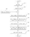
영상 획득부(12)로부터 획득된 영상을 입력받고(S50), 영상의 각 픽셀에 대한 그래디언트를 계산한다(S52). 그래디언트 계산은 영상 내의 각 픽셀에 대하여 도 3과 같은 윈도우를 적용하여 수평 그래디언트(dx) 및 수직 그래디언트(dy)를 계산함으로써 이루어질 수 있다. 수평 그래디언트(dx)는 수평 윈도우의 각 값을 픽셀의 인텐시티 값에 곱한 합으로 구할 수 있으며, 수직 그래디언트(dy)는 수직 윈도우의 각 값을 픽셀의 인텐시티 값에 곱한 합으로 구할 수 있다.The image acquired from the
특징점 추출부(26)에서 추출된 특징점(바람직하게는 코너)의 좌표를 입력받아(S54), 특징점을 중심으로 한 영상 패치를 설정한다(S56). 영상 패치를 설정함에 있어서 일 실시예로 9×9 픽셀을 특정할 수 있다. 다만, 실제 실시에 있어서 영상 패치의 크기는 상기한 바에 한정되는 것은 아니며 입력 영상과 적용 환경에 따라 가변적일 수 있음은 물론이다.The coordinates of the feature points (preferably corners) extracted by the feature point extractor 26 are input (S54), and an image patch based on the feature points is set (S56). In setting the image patch, in an embodiment, 9 × 9 pixels may be specified. However, in actual implementation, the size of the image patch is not limited to the above, and may vary depending on the input image and the application environment.
영상 패치 내 각 픽셀에 대한 그래디언트를 이용하여 각 픽셀에서 그래디언트의 위상(phase)과 크기(magnitude)를 계산한다(S58). 위상은 수학식 5에 의해, 크기는 수학식 6에 의해 계산될 수 있다. 수학식 6과 7에서 dx는 특정 픽셀에 대한 수평 그래디언트이고, dy는 특정 픽셀에 대한 수직 그래디언트이다.The phase and magnitude of the gradient in each pixel are calculated using the gradient for each pixel in the image patch (S58). The phase may be calculated by Equation 5 and the magnitude by


다음으로, 영상 패치를 더 작은 영역으로 재분할하여 다수 개의 서브 영역(Sub Region)을 생성한다(S60). 발명의 실시에 있어서 9×9 영상 패치의 경우 3×3 서브 영역으로 분할하여 9개의 서브 영역으로 구분할 수 있다.Next, the image patch is subdivided into smaller regions to generate a plurality of sub regions (S60). In the embodiment of the present invention, a 9 × 9 image patch may be divided into 3 × 3 sub-regions and divided into 9 sub-regions.
각각의 서브 영역에 대하여, 서브 영역을 구성하는 각 픽셀별 위상에 대한 히스토그램(histogram)을 작성하여 이에 대한 피크 값에 따른 위상을 해당 서브 영역의 지역적 방향으로 지정한다(S62). 도 4의 (a)는 영상 패치의 일례를 나타내며, (b)는 영상 패치의 서브 영역에 대한 지역적 방향 정보를 나타낸다. 도 4의 (b)의 경우 총 9개의 지역적 방향 정보가 추출되었음을 확인할 수 있다.For each subregion, a histogram of a phase for each pixel constituting the subregion is created and the phase according to the peak value thereof is designated in the local direction of the corresponding subregion (S62). 4A illustrates an example of an image patch, and FIG. 4B illustrates regional direction information on a sub region of the image patch. In the case of FIG. 4B, it can be confirmed that a total of nine regional direction information is extracted.
이렇게 추출된 서브 영역의 지역적 방향 정보를 두 개씩 쌍을 지어 pair-wise 조합을 생성하고, 각 조합의 국지적 방위 정보의 각도 차이를 기술자로서 기록한다(S64). 9개의 국지적 방위가 추출된 경우 pair-wise 조합은 총 36개가 생성될 것이며(1-2, 1-3, 1-4,..., 8-9), 특정 특징점에 대한 기술자는 36개의 값으로서 나타낼 수 있게 된다. 다만, 본 발명에 따른 기술자에 있어서 9개의 지역적 방향 정보를 pair-wise 조합으로 생성하는 것은 지역적 방향 정보의 관계를 생성하는 일례를 설명한 것으로 이해되어야 할 것이며, 지역적 방향 정보는 그 자체 또는 다른 조합에 따른 기술자로서 이용될 수 있음은 물론이다.A pair-wise combination is generated by pairing two pieces of regional direction information of the extracted sub-region, and the angle difference of the local orientation information of each combination is recorded as a descriptor (S64). If 9 local orientations are extracted, a total of 36 pair-wise combinations will be generated (1-2, 1-3, 1-4, ..., 8-9), and the descriptor for a particular feature point has 36 values. Can be represented as However, in the descriptor according to the present invention, it is to be understood that the generation of nine regional direction information in a pair-wise combination has been described as an example of generating a relationship of the regional direction information, and the local direction information may be used in itself or in another combination. Of course, it can be used as a technician according.
이상에서 설명한 지역적 방향 기술자는 기존의 다른 기술자에 비해 오인식률 이 줄어들고, 특징점 매칭을 위한 시간이 단축되며 회전 변화에 강인하다는 장점이 있다.The regional direction descriptor described above has the advantage of reducing the false recognition rate, shortening the time for feature point matching, and being robust against rotational changes compared to other existing technicians.
다음으로 주행 모드 선택부(32)의 기능 및 주행 모드 선택부(32)의 주행 모드 선택에 따른 이동 로봇(10)에 대한 주행 제어를 설명한다.Next, the driving control for the
이러한 관계를 이동 로봇(10)의 주행 제어에 적용하면 다음과 같다.Applying this relationship to the traveling control of the
이동 로봇(10)은 관성 센서(44)와 엔코더(46)의 주행 정보를 바탕으로 위치를 추정하고 실시간으로 지도를 생성한다. 주행 제어부(38)는 EKF를 활용하여 이동 로봇(10)의 이동 방향과 이동 거리로부터 추정된 매칭 범위를 이용하여, 영상 획득부(12)에서 순차적으로 획득되는 영상 간의 특징점 매칭을 수행한다. 이를 본 발명에서는 '단기저 주행 모드'라고 정의한다.The
단기저 주행 모드에서는, 주행 제어부(38)의 EKF에 의해 예측되는 범위 내에서 이동 로봇(10)의 위치 및 주행을 제어하는데, 영상 획득부(12)에서 획득된 영상을 처리하여 특징점을 추출하고 특징점에 대한 기술자를 생성하며, 생성된 기술자를 이용하여 특징점 매칭을 수행함으로써 이동 로봇(10)의 정확한 위치를 추정하여 주행 정보(odometry)에 따른 이동 로봇(10)의 위치를 보정한다.In the short-term low travel mode, the position and the travel of the
그런데 이동 로봇(10)이 관성 센서(44)와 엔코더(46)로부터 획득한 주행 정보에 심각한 오류가 발생하는 경우에는 주행 제어부(38)에서 EKF를 이용하여 이동 로봇(10)의 위치를 추정하고 영상의 특징점 추출을 통해 위치를 보정하는 것이 불가능해진다. 예컨대 이동 로봇(10)이 이동 중에 장애물에 끼인 경우 로봇 구동부(40)의 구동 모터가 회전하더라도 이동 로봇(10)은 위치가 변화하지 않는다. 그 러나 엔코더(46)는 구동 모터의 회전을 감지하므로 주행 제어부(38)는 이동 로봇(10)이 이동하고 있는 것으로 판단하게 된다. 이 경우 이동 로봇(10)의 위치 추정은 어렵게 된다. 또는, 이동 로봇(10)의 주행 바퀴가 슬립되어 주행이 이루어지지 않거나 원하지 않는 방향으로 회전하는 경우에도 이동 로봇(10)의 위치 추정에 따른 오차는 극복될 수 없게 된다. 이러한 경우에는 이동 로봇(10)은 상술한 단기저 주행 모드를 포기하고 장기저 주행 모드로 주행하도록 제어된다.However, when a serious error occurs in the driving information obtained by the
장기저 주행 모드에서는 관성 센서(44) 및 엔코더(46)의 주행 정보를 이용하지 않고 영상 획득부(12)에서 획득한 영상의 매칭을 통해 이동 로봇(10)의 위치를 판단하고 주행을 제어한다.In the long-term low driving mode, the position of the
그런데, 단기저 주행 모드에서는 이동 로봇(10)의 주행 정보와 추정된 위치를 바탕으로 영상에서 추출한 특징점을 활용하게 되는바, 특징점의 정확도가 높지 않은 것이 일반적이다. 이에 따라 서로 다른 위치의 특징점이 같은 것으로 오인식될 수 있는 우려가 있다. 그러나 장기저 주행 모드에 있어서는 영상 정합만을 활용하여 이동 로봇(10)의 위치를 추정하게 되므로 특징점의 정확도다 높을 필요가 있다.However, in the short-term low driving mode, the feature points extracted from the image are utilized based on the driving information and the estimated position of the
특징점 추출부(26)에서는 특징점의 강도가 소정값(제 1 기준값) 이상의 것을 특징점으로 추출하고 기술자 생성부(28)에서 특징점에 대한 기술자를 생성한다. 이들은 단기저 주행 모드에서 사용된다. 장기저 주행 모드에서는 보다 정확도가 높은 특징점이 요구되므로, 특징점 추출부(26)에서 추출된 특징점 중 특징점의 강도가 제 2 기준값(〉제 1 기준값) 이상인 특징점은 특징점 관리부(34)에서 '핵심 영역 특징점(keyarea feature)'으로 관리한다. 특징점으로 영상의 코너를 사용하는 경우라면, 수학식 4에 따른 코너 반응 함수값을 기준으로 특징점을 추출하게 될 것이며, 코너 반응 함수값이 제 2 기준값 이상이라면 핵심 영역 특징점으로 설정하게 될 것이다.The feature point extractor 26 extracts a feature point whose strength of the feature point is greater than or equal to a predetermined value (first reference value), and the descriptor generator 28 generates a descriptor for the feature point. These are used in the short run mode. In the long-term low running mode, a more accurate feature point is required. Therefore, the feature point of the feature points extracted by the feature point extractor 26 has a strength greater than or equal to the second reference value (> first reference value). 'Keyarea feature'. In the case of using the corner of the image as the feature point, the feature point will be extracted based on the corner response function value according to
바람직하게는 상기 핵심 영역 특징점은 이동 로봇(10)이 활동하는 공간에서 일정 거리를 두고 설정되도록 한다. 이는 핵심 영역 특징점이 특정 영역에 중첩되는 것을 방지하기 위함이다. 이를 위해 핵심 영역 특징점의 대상이 특정 영역에 중첩되어 추출된 경우에는 어느 하나를 선택하는 것이 바람직하다.Preferably, the key region feature point is set at a certain distance from the space in which the
한편, 핵심 영역 특징점에 대해서는 추출된 코너 주변의 영상을 이용하여 지역적 방향 기술자를 생성하고 kd-tree 형태로 전체 영상으로 표상하도록 하는 것이 바람직하다. 장기저 주행 모드에 있어서는 영상 획득부(12)에서 획득된 영상에서 특징점을 kd-tree 형태로 추출하고 기 등록된 핵심 영역 특징점과의 유사도를 판단한다. 이 때 계산 속도를 높이기 위하여 BBF(Best Bin First) 알고리즘을 적용하고 RANSAC(Random Sample Concensus) 알고리즘을 사용하여 에러율을 낮추도록 할 수 있다.On the other hand, it is desirable to generate a local direction descriptor using the extracted image around the corner and to represent the entire image in the form of kd-tree for the key region feature points. In the long-term low driving mode, the feature point is extracted from the image acquired by the
주행 모드 선택부(32)는 기본적인 상황에서는 단기저 주행 모드(제 1 주행 모드)로 이동 로봇(10)의 주행 제어가 이루어지도록 선택하고, 상기한 바와 같이 특수한 상황에서는 장기저 주행 모드(제 2 주행 모드)로 이동 로봇(10)의 주행 제어가 이루어지도록 선택한다. 장기저 주행 모드로 이동 로봇(10)의 주행 제어가 이루어지는 경우에, 주제어부(30)는 영상 획득부(12)가 획득된 영상에서 핵심 영역 특징점을 추출하고 이를 기 저장된 핵심 영역 특징점과 매칭시켜 이동 로봇(10)의 주행을 제어하고, 이동 로봇(10)의 지도상의 위치가 복구되는 경우 다시 단기저 주행 모드로 변환한다.The driving mode selection unit 32 selects the driving control of the
즉, 코너 추출 방법은 기본적으로 해리스 코너(harris corner) 방법과 동일하지만, KLT 알고리즘을 바로 적용하기에는 청소로봇의 경우 영상 간의 차이가 큽니다. 그렇다고 장기저 주행모드(widebaseline)의 대표격인 SIFT 알고리즘으로 영상을 매칭하는 경우에는 시간이 너무 걸려서 실시간에는 적합하지 않습니다.In other words, the corner extraction method is basically the same as the Harris corner method, but for the robot to apply the KLT algorithm immediately, the difference between the images is large. However, it is too time-consuming to match images with the SIFT algorithm, which is representative of widebaseline, which is not suitable for real time.
상술한 바와 같이 본 발명에서는 상기 이동 로봇이 대상 영역의 주행을 위하여 2가지 지도를 구축하며, 단기저 주행시에 생성하는 메트릭 지도(metric map)와 장기저 주행모드시 위치 복구를 위하여 상향 영상을 기반으로 하는 토폴로지 지도(topological map)을 구축합니다.As described above, in the present invention, the mobile robot constructs two maps for driving the target area, and generates a metric map generated during short-term low driving and an upward image for position recovery in the long-term low driving mode. Construct a topological map.
상기 메트릭 지도는 KLT 트래커(KLT tracker)처럼 추적하기 좋은 코너들을 선택하여, 코너 반응함수에 따라 코너들을 정렬한 후 지역적으로 균일하게 분포하여 EKF를 이용하여 오도메트리 정보를 참조하여 지도 랜드마크를 생성할 수 있도록 합니다. 본 발명에서는 상기 메트릭 지도(metric map)에서 코너 주위에 개별적으로 방향적 기술자를 이용하여 랜드마크를 표현함으로써, 어파인(affine) 변형이 일어나는 벽면이나 조명변화에 강인하게 개별적으로 강한 구분력을 지닌다.The metric map selects corners that are easy to track like a KLT tracker, arranges the corners according to the corner response function, and then distributes the map uniformly by using EKF to map the map landmarks. To be created. In the present invention, by representing the landmark by using the directional descriptor around the corner individually in the metric map, it has a strong discriminating power individually to be strong against the wall surface or the lighting change where affine deformation occurs. .
또한 토폴로지 지도(topological map)는 메트릭 지도(metric map)에서 추출된 코너들의 반응함수의 합이 정해진 문턱값(threshold)보다 큰 영상에 대하여 메트릭 지도와 달리 사물인식과 같이 코너를 보다 많이 추출하고 국지적 최대 값(local maxima)의 제한을 없앤다. 그리고 많이 추출된 코너 주위에서 지역적 방향기술자를 생성하고 이를 kd tree 형태로 전체를 나타낸다. 나중에 이를 이용하여 이미지 간의 포즈를 추정함으로써 로봇의 위치를 복구할 수 있다.In addition, the topological map extracts more corners like local object recognition and extracts more corners than the metric map for the image where the sum of the response functions of the corners extracted from the metric map is larger than the predetermined threshold. Remove the limit of local maxima. We then create a local direction descriptor around the many extracted corners and represent the whole in the form of a kd tree. You can later use it to recover the position of the robot by estimating the pose between images.
그러므로, 본 발명에서는 이동 로봇이 제 1 주행 모드로 주행을 시작하여 키드냅 인지하는 방법(바닥 IR 센서 또는 자이로 오도메트리를 이용)이나 일정 프레임 이상 동안 메트릭 지도 매칭이 실패한 경우에 상기 제 2 주행 모드로 전환한다. 상기 제 2 주행 모드에서는 토폴로지 지도(topological map)에 KD 트리 형태로 저장된 영상과 BBF, RANSAC알고리즘을 이용하여 매칭되는 경우 위치 복원을 시도한다.Therefore, in the present invention, when the mobile robot starts driving in the first driving mode and recognizes the kid snap (using a floor IR sensor or a gyro odometry) or when the metric map matching fails for a predetermined frame or more, the second driving is performed. Switch to mode. In the second driving mode, when the image stored in the topological map in the form of a KD tree is matched using a BBF or RANSAC algorithm, the position restoration is attempted.
이상의 설명에 따른 이동 로봇(10)의 주행 제어 방법을 설명하면 다음과 같다.Referring to the driving control method of the
도 5는 본 발명의 바람직한 실시예에 따른 이동 로봇의 위치 인식 및 주행 제어 방법에 있어서 특징점 추출 및 식별자 생성 과정을 도시한 순서도이다.FIG. 5 is a flowchart illustrating a feature point extraction and identifier generation process in a position recognition and driving control method of a mobile robot according to an exemplary embodiment of the present invention.
영상 획득부(12)는 이동 로봇(10)의 주변 환경에 대한 영상을 획득한다(S70). 영상 왜곡 보정부(22)는 획득된 영상의 왜곡을 보정한다(S72). 영상 품질 점검부(24)는 영상 품질을 점검하고(S74), 영상 품질이 특징점 추출에 적합한 경우에만 다음 단계가 수행된다.The
특징점 추출부(26)는 입력 영상으로부터 특징점을 추출하고(S76), 기술자 생성부는 특징점에 대한 기술자를 생성한 후(S78), 특징점 관리부(34)는 생성된 특징점이 신규인 경우 이를 등록하여 관리한다(S80).The feature point extractor 26 extracts a feature point from the input image (S76), the descriptor generator generates a descriptor for the feature point (S78), and the feature point manager 34 registers and manages the generated feature point if it is new. (S80).
한편, 특징점 추출부(26)에서 추출된 특징점이 핵심 영역 특징점에 해당하는 것으로 판정되는 경우(S82), 핵심 영역 특징점에 대한 기술자를 생성하고(S84), 특징점 관리부(34)는 핵심 영역 특징점이 신규인 경우 이를 등록하여 관리한다(S86).On the other hand, if it is determined that the feature point extracted by the feature point extractor 26 corresponds to the key region feature point (S82), a descriptor for the key region feature point is generated (S84), and the feature point manager 34 is the key region feature point. If new, it is registered and managed (S86).
도 6은 본 발명의 바람직한 실시예에 따른 이동 로봇의 위치 인식 및 주행 제어 방법에 있어서, 주행 모드의 선택 및 주행 제어 방법을 도시한 순서도이다.6 is a flowchart illustrating a driving mode selection and driving control method in a position recognition and driving control method of a mobile robot according to an exemplary embodiment of the present invention.
주행 모드 선택부(32)는 이동 로봇(10)의 주행 상태에 따라 주행 모드를 선택한다(S90).The driving mode selector 32 selects a driving mode according to the driving state of the mobile robot 10 (S90).
통상적인 경우에는 주행모드 선택부(32)는 제 1 주행 모드(단기저 주행 모드)를 선택하여 관성 센서(44) 및 엔코더(46)로부터 획득된 주행정보와 입력 영상의 특징점에 기반한 위치 인식 및 주행 제어를 수행한다.In a typical case, the driving mode selector 32 selects a first driving mode (short-term driving mode) and recognizes a position based on driving information obtained from the inertial sensor 44 and the
제 1 주행 모드가 선택된 경우, 영상 획득부(12)에서 획득된 입력 영상에 대한 특징점을 추출하고 이에 대한 기술자를 생성한다(S94). 다음으로 입력 영상에 대해 생성된 기술자를 이용하여 입력 영상의 특징점과 등록된 특징점과의 매칭을 수행한다(S96).When the first driving mode is selected, the feature point of the input image acquired by the
한편, 주제어부(30)는 관성 센서(44) 및 엔코더(46)로부터 이동 로봇(10)의 주행 정보를 입력받는다(S98).On the other hand, the main controller 30 receives the driving information of the
주행 제어부(38)는 이동 로봇(10)의 주행 정보를 바탕으로 이동 로봇의 위치를 예측하고, 입력된 영상을 바탕으로 이동 로봇의 위치를 보정하여 이동 로봇의 주행을 제어한다(S100).The driving
그러나, 이동 로봇(10)이 장애물에 끼거나 슬립이 발생한 경우에는 주행 모드 선택부(32)는 제 2 주행 모드(장기저 주행 모드)를 선택한다(S102).However, when the
제 2 주행 모드가 선택된 경우, 영상 획득부(12)에서 획득된 입력 영상으로부터 핵심 영역 특징점을 추출하고 핵심 영역 특징점에 대한 기술자를 생성한다(S104).When the second driving mode is selected, the key region feature point is extracted from the input image acquired by the
특징점 관리부(34)는 입력 영상의 핵심 영역 특징점과 등록된 핵심 영역 특징점을 매칭시켜 이동 로봇(10)의 실제 위치를 확인한다(S106).The feature point manager 34 checks the actual position of the
주행 제어부(38)는 핵심 영역 특징점에 따른 영상 정합에 기반하여 이동 로봇(10)의 위치를 인식하고 주행을 제어한다(S108).The driving
한편, 상기 S102단계에 따라 제 2 주행 모드가 선택된 경우, 이동 로봇(10)을 후진시키거나 랜덤한 방향으로 이동시키는 것이 바람직하다. 이는 특징점 추출부(26)에서 영상 획득부(12)에서 획득된 영상으로부터 핵심 영역 특징점을 추출할 수 있는 영역으로 이동시키기 위함이다.On the other hand, when the second driving mode is selected according to step S102, it is preferable to move the
특징점 관리부(34)는 영상 획득부(12)에서 신규로 획득된 영상에서 추출한 특징점과 기 등록된 특징점을 매칭하여 특징점의 일치 여부를 판단하는데 특징점의 오인식이 종종 발생한다. 이러한 특징점 오인식을 방지하기 위하여, 본 발명은 이미 설명한 지역적 방향 정보와 관성 센서(44)를 이용한 이동 로봇(10)의 주행 방향(heading) 정보를 함께 활용하는 방안을 제안한다.The feature point manager 34 often matches a feature point extracted from a newly acquired image by the
도 7은 본 발명의 바람직한 실시예에 따른 이동 로봇에 있어서 제 1 위치에 서의 이동 로봇의 주행 방향과 영상 패치의 주된 방향의 관계를 도시한 도면이고, 도 8은 본 발명의 바람직한 실시예에 따른 이동 로봇에 있어서 제 2 위치에서의 이동 로봇의 주행 방향과 영상 패치의 주된 방향의 관계를 도시한 도면이다.FIG. 7 is a view showing a relationship between a driving direction of a mobile robot at a first position and a main direction of an image patch in the mobile robot according to the preferred embodiment of the present invention, and FIG. 8 is a view showing a preferred embodiment of the present invention. It is a figure which shows the relationship between the traveling direction of a mobile robot in a 2nd position, and the main direction of an image patch in the mobile robot.
설명의 편의를 위해 도 7에서의 영상 패치를 제 1 영상 패치(110)라 하고, 도 8에서의 영상 패치를 제 2 영상 패치(112)라 한다.For convenience of description, the image patch in FIG. 7 is called a
영상 패치는 전술한 바와 같이 특징점을 중심으로 일정 범위의 영상을 구획한 것이다. 영상 패치의 주된 방향(114, 116)은 영상 패치의 각 픽셀에 대한 위상(phase) 정보에 대한 히스트그램을 작성하고 피크에 해당하는 것으로 설정될 수 있다.As described above, the image patch divides a predetermined range of images around the feature points. The
이동 로봇(10)의 주행 방향은 이동 로봇(10)이 주행하고 있는 방향을 의미하며 초기 주행 방향을 기준으로 상대적으로 계산된다.The driving direction of the
도 7에 따른 제 1 위치에서 이동 로봇(10)의 주행 방향을 α1이라고 하고, 이동 로봇(10)의 영상 획득부(12)에서 획득된 제 1 영상 패치(110)의 주된 방향(114)을 θ1이라 하자.The driving direction of the
한편, 도 8에 따른 제 2 위치에서 이동 로봇(10)의 주행 방향을 α2라고 하고, 이동 로봇(10)의 영상 획득부(12)에서 획득된 제 2 영상 패치(112)의 주된 방향(116)을 θ2라고 하자.Meanwhile, the driving direction of the
만약, 제 1 영상 패치(110)와 제 2 영상 패치(112)가 동일한 특징점에 대한 것이라면, 이론적으로는 제 2 영상 패치(112)의 주된 방향(116)은 제 1 영상 패 치(110)의 주된 방향(114)에 비해 이동 로봇(10)의 주행 방향이 변화한 각도만큼 상대적으로 변화할 것이다. 이는 영상 획득부(12)가 이동 로봇(10)에 고정된 상태로 부착되었기 때문이다. 이를 수학식으로 표현하면 수학식 8과 같으며, 도 9는 이동 로봇의 주행 방향의 변화와 그에 따른 영상 패치의 주된 방향의 변화와의 관계를 도시한 도면이다.If the

그러나, 실제적으로는 특징점을 중심으로 한 영상 패치에 대한 주된 방향의 계산 과정 및 이동 로봇의 주행 정보 획득에 있어서 오차가 발생할 수 있으므로 수학식 8과 같이 될 수는 없다. 따라서 이동 로봇(10)의 주행 방향의 변화에 따른 영상 패치의 주된 방향의 변화가 수학식 9와 같이 소정 범위(예컨대 45°) 이내라면 상기 제 1 위치와 제 2 위치에서의 특징점이 동일한 것으로 판단될 수 있을 것이다.However, in practice, an error may occur in the calculation process of the main direction of the image patch around the feature point and the acquisition of the driving information of the mobile robot, and thus cannot be expressed as

제 1 위치와 제 2 위치에서의 영상 패치의 주된 방향의 차이와 이동 로봇(10)의 주행 방향의 변화가 상기 조건을 만족하는지 여부는 2가지 방법으로 활용될 수 있다.Whether the difference between the main direction of the image patch at the first position and the second position and the change in the driving direction of the
첫째는 제 1 위치에서의 특징점과 제 2 위치에서의 특징점이 일치하는 것으 로 판단되는 경우, 상기 조건을 추가적으로 만족하는 경우에 동일한 특징점으로 판단될 수 있다. 둘째는 상기 조건을 만족하는 경우에만 제 1 위치에서의 특징점과 제 2 위치에서의 특징점의 매칭을 수행한다.First, when it is determined that the feature point at the first position and the feature point at the second position coincide, the same feature point may be determined when the condition is additionally satisfied. Secondly, the feature point at the first position and the feature point at the second position are matched only when the condition is satisfied.
위의 어느 경우에든 특징점 매칭의 정확성을 향상시켜 특징점 오인식을 방지할 수 있게 된다.In any of the above cases, it is possible to prevent the feature point misrecognition by improving the accuracy of the feature point matching.
이상의 설명은 본 발명의 기술 사상을 예시적으로 설명한 것에 불과한 것으로서, 본 발명이 속하는 기술 분야에서 통상의 지식을 가진 자라면 본 발명의 본질적인 특성에서 벗어나지 않는 범위 내에서 다양한 수정, 변경 및 치환이 가능할 것이다. 따라서, 본 발명에 개시된 실시예 및 첨부된 도면들은 본 발명의 기술 사상을 한정하기 위한 것이 아니라 설명하기 위한 것이고, 이러한 실시예 및 첨부된 도면에 의하여 본 발명의 기술 사상의 범위가 한정되는 것은 아니다. 본 발명의 보호 범위는 아래의 청구범위에 의하여 해석되어야 하며, 그와 동등한 범위 내에 있는 모든 기술 사상은 본 발명의 권리범위에 포함되는 것으로 해석되어야 할 것이다.The above description is merely illustrative of the technical idea of the present invention, and various modifications, changes, and substitutions may be made by those skilled in the art without departing from the essential characteristics of the present invention. will be. Accordingly, the embodiments disclosed in the present invention and the accompanying drawings are not intended to limit the technical spirit of the present invention but to describe the present invention, and the scope of the technical idea of the present invention is not limited by the embodiments and the accompanying drawings. . The protection scope of the present invention should be interpreted by the following claims, and all technical ideas within the equivalent scope should be interpreted as being included in the scope of the present invention.
도 1은 본 발명의 바람직한 실시예에 따른 이동 로봇의 구성을 도시한 블록도,1 is a block diagram showing the configuration of a mobile robot according to a preferred embodiment of the present invention;
도 2는 본 발명의 바람직한 실시예에 따른 이동 로봇에 있어서 지역적 방향 기술자의 생성 과정을 도시한 도면,2 is a view showing a process of generating a local direction descriptor in a mobile robot according to an embodiment of the present invention;
도 3은 영상의 그래디언트를 계산하기 위한 윈도우를 예시한 도면,3 is a diagram illustrating a window for calculating a gradient of an image;
도 4는 영상 패치의 일례(a) 및 영상 패치의 서브 영역에 대한 지역적 방향 정보(b)의 일례를 도시한 도면,4 shows an example of an image patch (a) and an example of local direction information (b) for a sub region of the image patch;
도 5는 본 발명의 바람직한 실시예에 따른 이동 로봇의 위치 인식 및 주행 제어 방법에 있어서 특징점 추출 및 식별자 생성 과정을 도시한 순서도,FIG. 5 is a flowchart illustrating a feature point extraction and identifier generation process in a position recognition and driving control method of a mobile robot according to an embodiment of the present invention; FIG.
도 6은 본 발명의 바람직한 실시예에 따른 이동 로봇의 위치 인식 및 주행 제어 방법에 있어서, 주행 모드의 선택 및 주행 제어 방법을 도시한 순서도,6 is a flowchart illustrating a driving mode selection and driving control method in a position recognition and driving control method of a mobile robot according to an exemplary embodiment of the present invention;
도 7은 본 발명의 바람직한 실시예에 따른 이동 로봇에 있어서 제 1 위치에서의 이동 로봇의 주행 방향과 영상 패치의 주된 방향의 관계를 도시한 도면,7 is a view showing a relationship between the traveling direction of the mobile robot at the first position and the main direction of the image patch in the mobile robot according to a preferred embodiment of the present invention;
도 8은 본 발명의 바람직한 실시예에 따른 이동 로봇에 있어서 제 2 위치에서의 이동 로봇의 주행 방향과 영상 패치의 주된 방향의 관계를 도시한 도면,8 is a view showing the relationship between the traveling direction of the mobile robot at the second position and the main direction of the image patch in the mobile robot according to a preferred embodiment of the present invention;
도 9는 이동 로봇의 주행 방향의 변화와 그에 따른 영상 패치의 주된 방향의 변화와의 관계를 도시한 도면이다.FIG. 9 is a diagram illustrating a relationship between a change in a driving direction of a mobile robot and a change in a main direction of an image patch.
<도면의 주요 부분에 대한 도면부호의 설명><Description of reference numerals for the main parts of the drawings>
10 : 이동 로봇 12 : 영상 획득부10: mobile robot 12: image acquisition unit
20 : 영상 처리부22 : 영상 왜곡 보정부20: image processing unit 22: image distortion correction unit
24 : 영상 품질 점검부26 : 특징점 추출부24: image quality checking unit 26: feature point extraction unit
28 : 기술자 생성부30 : 주제어부28: engineer generation unit 30: main control unit
32 : 주행모드 선택부34 : 특징점 관리부32: driving mode selection unit 34: feature point management unit
36 : 지도 관리부38 : 주행 제어부36: map management unit 38: driving control unit
40 : 로봇 구동부42 : 센서부40: robot drive unit 42: sensor unit
44 : 관성 센서46 : 엔코더44: inertial sensor 46: encoder
Claims (24)
Translated fromKoreanPriority Applications (1)
| Application Number | Priority Date | Filing Date | Title |
|---|---|---|---|
| KR1020090069066AKR101618030B1 (en) | 2009-07-28 | 2009-07-28 | Method for Recognizing Position and Controlling Movement of a Mobile Robot, and the Mobile Robot Using the same |
Applications Claiming Priority (1)
| Application Number | Priority Date | Filing Date | Title |
|---|---|---|---|
| KR1020090069066AKR101618030B1 (en) | 2009-07-28 | 2009-07-28 | Method for Recognizing Position and Controlling Movement of a Mobile Robot, and the Mobile Robot Using the same |
Publications (2)
| Publication Number | Publication Date |
|---|---|
| KR20110011424Atrue KR20110011424A (en) | 2011-02-08 |
| KR101618030B1 KR101618030B1 (en) | 2016-05-09 |
Family
ID=43771633
Family Applications (1)
| Application Number | Title | Priority Date | Filing Date |
|---|---|---|---|
| KR1020090069066AActiveKR101618030B1 (en) | 2009-07-28 | 2009-07-28 | Method for Recognizing Position and Controlling Movement of a Mobile Robot, and the Mobile Robot Using the same |
Country Status (1)
| Country | Link |
|---|---|
| KR (1) | KR101618030B1 (en) |
Cited By (27)
| Publication number | Priority date | Publication date | Assignee | Title |
|---|---|---|---|---|
| KR101140558B1 (en)* | 2011-10-17 | 2012-05-02 | 국방과학연구소 | Autonomous mobile robot and control method for the same |
| KR20130000278A (en)* | 2011-06-22 | 2013-01-02 | 엘지전자 주식회사 | Robot cleaner and controlling method of the same |
| KR101223480B1 (en)* | 2011-09-20 | 2013-01-17 | 엘지전자 주식회사 | Mobile robot and controlling method of the same |
| KR101314732B1 (en)* | 2011-08-10 | 2013-10-08 | (주)로봇에버 | Provision method for robot control information and navigation device for robot control using the same |
| KR101366860B1 (en)* | 2011-09-20 | 2014-02-21 | 엘지전자 주식회사 | Mobile robot and controlling method of the same |
| KR20140032116A (en)* | 2012-09-06 | 2014-03-14 | (주)하기소닉 | Method for localizing intelligent mobile robot by using natural landmark, artificial landmark and inertial sensor |
| KR101376536B1 (en)* | 2012-09-04 | 2014-03-19 | 한국생산기술연구원 | Position Recognition Method for mobile object using convergence of sensors and Apparatus thereof |
| KR20140053712A (en)* | 2012-10-26 | 2014-05-08 | (주)하기소닉 | The localization method for indoor mobile robots by sensor fusion |
| KR101412513B1 (en)* | 2013-07-19 | 2014-06-26 | (주)나임기술 | Method and system for controlling robot arm using frame grabber board |
| KR101398142B1 (en)* | 2012-09-04 | 2014-06-27 | 엘지전자 주식회사 | Moving robot and driving method of the same |
| KR20150138889A (en)* | 2014-05-30 | 2015-12-11 | 동명대학교산학협력단 | Apparatus and method for estimating the location of autonomous robot based on three-dimensional depth information |
| WO2015194866A1 (en)* | 2014-06-17 | 2015-12-23 | (주)유진로봇 | Device and method for recognizing location of mobile robot by means of edge-based readjustment |
| WO2018074904A1 (en)* | 2016-10-20 | 2018-04-26 | 엘지전자 주식회사 | Mobile robot and control method of mobile robot |
| WO2018160035A1 (en)* | 2017-03-03 | 2018-09-07 | 엘지전자 주식회사 | Mobile robot and control method therefor |
| US10133278B2 (en) | 2014-06-17 | 2018-11-20 | Yujin Robot Co., Ltd. | Apparatus of controlling movement of mobile robot mounted with wide angle camera and method thereof |
| US10133279B2 (en) | 2014-06-17 | 2018-11-20 | Yujin Robot Co., Ltd. | Apparatus of updating key frame of mobile robot and method thereof |
| KR20190011576A (en)* | 2017-07-25 | 2019-02-07 | 엘지전자 주식회사 | A moving-robot |
| US10275649B2 (en) | 2014-06-17 | 2019-04-30 | Yujin Robot Co., Ltd. | Apparatus of recognizing position of mobile robot using direct tracking and method thereof |
| US10307910B2 (en) | 2014-06-17 | 2019-06-04 | Yujin Robot Co., Ltd. | Apparatus of recognizing position of mobile robot using search based correlative matching and method thereof |
| WO2020153628A1 (en)* | 2019-01-22 | 2020-07-30 | 삼성전자주식회사 | Robot and control method thereof |
| KR102143349B1 (en)* | 2019-03-27 | 2020-08-11 | 엘지전자 주식회사 | Controlling method for Moving robot |
| CN112318507A (en)* | 2020-10-28 | 2021-02-05 | 内蒙古工业大学 | Robot intelligent control system based on SLAM technology |
| CN112686951A (en)* | 2020-12-07 | 2021-04-20 | 深圳乐动机器人有限公司 | Method, device, terminal and storage medium for determining robot position |
| WO2021221333A1 (en)* | 2020-04-29 | 2021-11-04 | 주식회사 모빌테크 | Method for predicting position of robot in real time through map information and image matching, and robot |
| WO2021241847A1 (en)* | 2020-05-28 | 2021-12-02 | 네이버랩스 주식회사 | Method and system for generating visual feature map |
| WO2023224295A1 (en)* | 2022-05-19 | 2023-11-23 | 엘지전자 주식회사 | Mobile robot and method for controlling mobile robot |
| KR20240023008A (en)* | 2022-08-12 | 2024-02-20 | 주식회사 클로봇 | Moving robot, method and program for outputting estimated position data in space of moving robot using position tracking model |
Families Citing this family (2)
| Publication number | Priority date | Publication date | Assignee | Title |
|---|---|---|---|---|
| KR102837968B1 (en)* | 2024-12-17 | 2025-07-24 | 리보틱스(주) | Method, computing device and computer program for estimating robot position using hierarchy-structured map data |
| KR102837969B1 (en)* | 2024-12-17 | 2025-07-24 | 리보틱스(주) | Method, computing device and computer program for precisely estimating robot position and orientation using low-resolution and high-resolution maps |
- 2009
- 2009-07-28KRKR1020090069066Apatent/KR101618030B1/enactiveActive
Cited By (39)
| Publication number | Priority date | Publication date | Assignee | Title |
|---|---|---|---|---|
| KR20130000278A (en)* | 2011-06-22 | 2013-01-02 | 엘지전자 주식회사 | Robot cleaner and controlling method of the same |
| KR101314732B1 (en)* | 2011-08-10 | 2013-10-08 | (주)로봇에버 | Provision method for robot control information and navigation device for robot control using the same |
| KR101223480B1 (en)* | 2011-09-20 | 2013-01-17 | 엘지전자 주식회사 | Mobile robot and controlling method of the same |
| KR101366860B1 (en)* | 2011-09-20 | 2014-02-21 | 엘지전자 주식회사 | Mobile robot and controlling method of the same |
| KR101140558B1 (en)* | 2011-10-17 | 2012-05-02 | 국방과학연구소 | Autonomous mobile robot and control method for the same |
| KR101376536B1 (en)* | 2012-09-04 | 2014-03-19 | 한국생산기술연구원 | Position Recognition Method for mobile object using convergence of sensors and Apparatus thereof |
| KR101398142B1 (en)* | 2012-09-04 | 2014-06-27 | 엘지전자 주식회사 | Moving robot and driving method of the same |
| KR20140032116A (en)* | 2012-09-06 | 2014-03-14 | (주)하기소닉 | Method for localizing intelligent mobile robot by using natural landmark, artificial landmark and inertial sensor |
| KR20140053712A (en)* | 2012-10-26 | 2014-05-08 | (주)하기소닉 | The localization method for indoor mobile robots by sensor fusion |
| KR101412513B1 (en)* | 2013-07-19 | 2014-06-26 | (주)나임기술 | Method and system for controlling robot arm using frame grabber board |
| KR20150138889A (en)* | 2014-05-30 | 2015-12-11 | 동명대학교산학협력단 | Apparatus and method for estimating the location of autonomous robot based on three-dimensional depth information |
| US10275649B2 (en) | 2014-06-17 | 2019-04-30 | Yujin Robot Co., Ltd. | Apparatus of recognizing position of mobile robot using direct tracking and method thereof |
| WO2015194866A1 (en)* | 2014-06-17 | 2015-12-23 | (주)유진로봇 | Device and method for recognizing location of mobile robot by means of edge-based readjustment |
| US10399228B2 (en) | 2014-06-17 | 2019-09-03 | Yujin Robot Co., Ltd. | Apparatus for recognizing position of mobile robot using edge based refinement and method thereof |
| US10307910B2 (en) | 2014-06-17 | 2019-06-04 | Yujin Robot Co., Ltd. | Apparatus of recognizing position of mobile robot using search based correlative matching and method thereof |
| US10133278B2 (en) | 2014-06-17 | 2018-11-20 | Yujin Robot Co., Ltd. | Apparatus of controlling movement of mobile robot mounted with wide angle camera and method thereof |
| US10133279B2 (en) | 2014-06-17 | 2018-11-20 | Yujin Robot Co., Ltd. | Apparatus of updating key frame of mobile robot and method thereof |
| US11175676B2 (en) | 2016-10-20 | 2021-11-16 | Lg Electronics Inc. | Mobile robot and method of controlling the same |
| WO2018074904A1 (en)* | 2016-10-20 | 2018-04-26 | 엘지전자 주식회사 | Mobile robot and control method of mobile robot |
| KR20180043753A (en)* | 2016-10-20 | 2018-04-30 | 엘지전자 주식회사 | A moving-robot and control method thereof |
| WO2018160035A1 (en)* | 2017-03-03 | 2018-09-07 | 엘지전자 주식회사 | Mobile robot and control method therefor |
| EP3590665A4 (en)* | 2017-03-03 | 2020-12-09 | LG Electronics Inc. -1- | Mobile robot and control method therefor |
| US11846950B2 (en) | 2017-03-03 | 2023-12-19 | Lg Electronics Inc. | Mobile robot and control method thereof |
| US11269343B2 (en) | 2017-03-03 | 2022-03-08 | Lg Electronics Inc. | Mobile robot and control method thereof |
| KR20190011576A (en)* | 2017-07-25 | 2019-02-07 | 엘지전자 주식회사 | A moving-robot |
| WO2020153628A1 (en)* | 2019-01-22 | 2020-07-30 | 삼성전자주식회사 | Robot and control method thereof |
| KR20200094831A (en)* | 2019-01-22 | 2020-08-10 | 삼성전자주식회사 | Robot and method for controlling thereof |
| US11938637B2 (en) | 2019-01-22 | 2024-03-26 | Samsung Electronics Co., Ltd. | Robot and control method thereof |
| KR102143349B1 (en)* | 2019-03-27 | 2020-08-11 | 엘지전자 주식회사 | Controlling method for Moving robot |
| US11348276B2 (en) | 2019-03-27 | 2022-05-31 | Lg Electronics Inc. | Mobile robot control method |
| WO2020197303A1 (en)* | 2019-03-27 | 2020-10-01 | Lg Electronics Inc. | Mobile robot control method |
| KR20210134117A (en)* | 2020-04-29 | 2021-11-09 | 주식회사 모빌테크 | Real-time robot position estimation metod through map information and image matching and the robot |
| WO2021221333A1 (en)* | 2020-04-29 | 2021-11-04 | 주식회사 모빌테크 | Method for predicting position of robot in real time through map information and image matching, and robot |
| WO2021241847A1 (en)* | 2020-05-28 | 2021-12-02 | 네이버랩스 주식회사 | Method and system for generating visual feature map |
| KR20210147855A (en)* | 2020-05-28 | 2021-12-07 | 네이버랩스 주식회사 | Method and system for generating visual feature map |
| CN112318507A (en)* | 2020-10-28 | 2021-02-05 | 内蒙古工业大学 | Robot intelligent control system based on SLAM technology |
| CN112686951A (en)* | 2020-12-07 | 2021-04-20 | 深圳乐动机器人有限公司 | Method, device, terminal and storage medium for determining robot position |
| WO2023224295A1 (en)* | 2022-05-19 | 2023-11-23 | 엘지전자 주식회사 | Mobile robot and method for controlling mobile robot |
| KR20240023008A (en)* | 2022-08-12 | 2024-02-20 | 주식회사 클로봇 | Moving robot, method and program for outputting estimated position data in space of moving robot using position tracking model |
Also Published As
| Publication number | Publication date |
|---|---|
| KR101618030B1 (en) | 2016-05-09 |
Similar Documents
| Publication | Publication Date | Title |
|---|---|---|
| KR101618030B1 (en) | Method for Recognizing Position and Controlling Movement of a Mobile Robot, and the Mobile Robot Using the same | |
| KR101083394B1 (en) | Apparatus and Method for Building and Updating a Map for Mobile Robot Localization | |
| EP2460629B1 (en) | Control method for localization and navigation of mobile robot and mobile robot using same | |
| US8903160B2 (en) | Apparatus and method with traveling path planning | |
| KR101725060B1 (en) | Apparatus for recognizing location mobile robot using key point based on gradient and method thereof | |
| KR101776621B1 (en) | Apparatus for recognizing location mobile robot using edge based refinement and method thereof | |
| KR101708659B1 (en) | Apparatus for recognizing location mobile robot using search based correlative matching and method thereof | |
| KR101538775B1 (en) | Apparatus and method for localization using forward images | |
| KR101152720B1 (en) | Apparaus and Method for Detecting Slip of a Mobile Robot | |
| KR101784183B1 (en) | APPARATUS FOR RECOGNIZING LOCATION MOBILE ROBOT USING KEY POINT BASED ON ADoG AND METHOD THEREOF | |
| KR20150144731A (en) | Apparatus for recognizing location mobile robot using edge based refinement and method thereof | |
| KR101456172B1 (en) | Localization of a mobile robot device, method and mobile robot | |
| KR102631313B1 (en) | Device capable of correcting location errors using real-time analysis and contrast between vision data and lidar data for the implementation of simultaneous localization and map-building technology | |
| KR102047303B1 (en) | Robot of estimating direction based on vanishing point of low luminance image and method estimating thereof | |
| KR101956569B1 (en) | Mobile robot and method for controlling the same | |
| JP2016148956A (en) | Positioning device, positioning method and positioning computer program | |
| KR20140053712A (en) | The localization method for indoor mobile robots by sensor fusion | |
| JP6886136B2 (en) | Alignment device, alignment method and computer program for alignment | |
| KR20220085682A (en) | Posture estimation fusion method and system using omnidirectional image sensor and inertial measurement sensor | |
| TW202215184A (en) | Automatic guided vehicle tracking system and automatic guided vehicle tracking method | |
| Bonin-Font et al. | A monocular mobile robot reactive navigation approach based on the inverse perspective transformation | |
| Carbonaro et al. | Landmark matching in a varying environment | |
| CN119839883B (en) | Intelligent household robot, task execution method thereof and storage medium | |
| KR102736388B1 (en) | Method for determining a pose of a robot, control server and buiding using the same | |
| KR20140032116A (en) | Method for localizing intelligent mobile robot by using natural landmark, artificial landmark and inertial sensor |
Legal Events
| Date | Code | Title | Description |
|---|---|---|---|
| PA0109 | Patent application | Patent event code:PA01091R01D Comment text:Patent Application Patent event date:20090728 | |
| PG1501 | Laying open of application | ||
| PA0201 | Request for examination | Patent event code:PA02012R01D Patent event date:20140331 Comment text:Request for Examination of Application Patent event code:PA02011R01I Patent event date:20090728 Comment text:Patent Application | |
| E902 | Notification of reason for refusal | ||
| PE0902 | Notice of grounds for rejection | Comment text:Notification of reason for refusal Patent event date:20150521 Patent event code:PE09021S01D | |
| E902 | Notification of reason for refusal | ||
| PE0902 | Notice of grounds for rejection | Comment text:Notification of reason for refusal Patent event date:20151126 Patent event code:PE09021S01D | |
| E701 | Decision to grant or registration of patent right | ||
| PE0701 | Decision of registration | Patent event code:PE07011S01D Comment text:Decision to Grant Registration Patent event date:20160224 | |
| GRNT | Written decision to grant | ||
| PR0701 | Registration of establishment | Comment text:Registration of Establishment Patent event date:20160428 Patent event code:PR07011E01D | |
| PR1002 | Payment of registration fee | Payment date:20160428 End annual number:3 Start annual number:1 | |
| PG1601 | Publication of registration | ||
| FPAY | Annual fee payment | Payment date:20190415 Year of fee payment:4 | |
| PR1001 | Payment of annual fee | Payment date:20190415 Start annual number:4 End annual number:4 | |
| PR1001 | Payment of annual fee | Payment date:20200416 Start annual number:5 End annual number:5 | |
| PR1001 | Payment of annual fee | Payment date:20210413 Start annual number:6 End annual number:6 | |
| PR1001 | Payment of annual fee | Payment date:20220404 Start annual number:7 End annual number:7 | |
| PR1001 | Payment of annual fee | Payment date:20240425 Start annual number:9 End annual number:9 |