KR20110010828A - Methods, systems, and tools for surgical procedures - Google Patents
Methods, systems, and tools for surgical proceduresDownload PDFInfo
- Publication number
- KR20110010828A KR20110010828AKR1020107029531AKR20107029531AKR20110010828AKR 20110010828 AKR20110010828 AKR 20110010828AKR 1020107029531 AKR1020107029531 AKR 1020107029531AKR 20107029531 AKR20107029531 AKR 20107029531AKR 20110010828 AKR20110010828 AKR 20110010828A
- Authority
- KR
- South Korea
- Prior art keywords
- neural
- surgical
- signal
- surgical tool
- instrument
- Prior art date
- Legal status (The legal status is an assumption and is not a legal conclusion. Google has not performed a legal analysis and makes no representation as to the accuracy of the status listed.)
- Withdrawn
Links
Images


Classifications
- A—HUMAN NECESSITIES
- A61—MEDICAL OR VETERINARY SCIENCE; HYGIENE
- A61B—DIAGNOSIS; SURGERY; IDENTIFICATION
- A61B17/00—Surgical instruments, devices or methods
- A61B17/16—Instruments for performing osteoclasis; Drills or chisels for bones; Trepans
- A61B17/1613—Component parts
- A61B17/1626—Control means; Display units
- A—HUMAN NECESSITIES
- A61—MEDICAL OR VETERINARY SCIENCE; HYGIENE
- A61B—DIAGNOSIS; SURGERY; IDENTIFICATION
- A61B17/00—Surgical instruments, devices or methods
- A61B17/16—Instruments for performing osteoclasis; Drills or chisels for bones; Trepans
- A61B17/1662—Instruments for performing osteoclasis; Drills or chisels for bones; Trepans for particular parts of the body
- A61B17/1671—Instruments for performing osteoclasis; Drills or chisels for bones; Trepans for particular parts of the body for the spine
- A—HUMAN NECESSITIES
- A61—MEDICAL OR VETERINARY SCIENCE; HYGIENE
- A61B—DIAGNOSIS; SURGERY; IDENTIFICATION
- A61B17/00—Surgical instruments, devices or methods
- A61B17/16—Instruments for performing osteoclasis; Drills or chisels for bones; Trepans
- A61B17/17—Guides or aligning means for drills, mills, pins or wires
- A61B17/1739—Guides or aligning means for drills, mills, pins or wires specially adapted for particular parts of the body
- A61B17/1757—Guides or aligning means for drills, mills, pins or wires specially adapted for particular parts of the body for the spine
Landscapes
- Health & Medical Sciences (AREA)
- Surgery (AREA)
- Life Sciences & Earth Sciences (AREA)
- Biomedical Technology (AREA)
- Medical Informatics (AREA)
- Orthopedic Medicine & Surgery (AREA)
- Oral & Maxillofacial Surgery (AREA)
- Engineering & Computer Science (AREA)
- Dentistry (AREA)
- Heart & Thoracic Surgery (AREA)
- Nuclear Medicine, Radiotherapy & Molecular Imaging (AREA)
- Molecular Biology (AREA)
- Animal Behavior & Ethology (AREA)
- General Health & Medical Sciences (AREA)
- Public Health (AREA)
- Veterinary Medicine (AREA)
- Surgical Instruments (AREA)
- Electrotherapy Devices (AREA)
- External Artificial Organs (AREA)
Abstract
Description
Translated fromKorean본 발명은 일반적으로 이식체와 함께 사용되는 시술 도구 및 시스템에 관한 것이며, 더욱 상세하게는, 전적인 것은 아니지만, 신경 통합 검사 시스템 및/또는 시술 항법 시스템에 무선 연결되는 시술 도구에 관한 것이다.FIELD OF THE INVENTION The present invention generally relates to surgical instruments and systems for use with implants, and more particularly, to surgical instruments that are wireless, but not exclusively, to neurointegration testing systems and / or surgical navigation systems.
척추적 병태 또는 질환 치료를 위하여 척추이식체는 척주의 하나 이상의 척추뼈에 또는 이를 따라 체결될 수 있다. 파스너(fastener)가 제공되어 이식체를 척주를 따라 특정 위치에 이식체를 고정시킨다. 척주를 고정시키거나 또는 안정화 운동 영역의 최소 일부 운동을 가능하게 하여, 이식체는 치료를 위하여 척주를 안정화시킨다.For the treatment of vertebral conditions or diseases, the grafted bodies may be fastened to or along one or more vertebrae of the spinal column. A fastener is provided to secure the implant at a particular location along the spinal column. By immobilizing the spinal column or allowing movement of at least some of the stabilizing motor region, the implant stabilizes the spinal column for treatment.
체결 이식체 예를 들면 로드 또는 판을 척주의 하나 이상의 운동 영역을 따라 고정시키기 위하여 다중-축 및 단일-축 나사가 사용된다. 뼈나사를 척추로드에 고정시키기 위하여 로드-볼트 커넥터를 사용하는 것은 척추뼈들을 함께 고정시키는 또 다른 방법이다. 이러한 파스너는 여러 부품들로 구성되어 있어 시술 중에 파스너를 배치하고 조작하는 것은 번거로운 일이다. 파스너를 척추 위치에 고정시키는 것은 대체로 수동 과정이며 무-전력 휴대용 도구가 사용된다.Multi-axis and single-axis screws are used to fasten fastening implants, such as rods or plates, along one or more regions of motion of the spinal column. Using a rod-bolt connector to secure the bone screw to the spinal rod is another way to secure the vertebrae together. These fasteners consist of several parts, so it is cumbersome to place and manipulate the fasteners during the procedure. The fastening of the fasteners to the spine position is usually a manual process and a power-free portable tool is used.
발명의 요약Summary of the Invention
기구 예를 들면 뼈 나사를 뼈 구조체에 이식하는 외과시술에서 사용되는 시술도구가 개시된다. 시술도구는 하우징 내에 배치되며 출력축과 체결된 모터를 포함한다. 격발기구는 출력축을 회전시키도록 모터에 전력을 선택적으로 공급하도록 구성된다. 신경신호 발생유닛은 출력축과 연결된 시술기구에 제공되는 기대전기신호를 발생하도록 구성된다. 따라서 시술기구는 기대전기신호의 신호전달체로 기능한다.Apparatuses for use in surgical procedures, such as implanting bone screws into bone structures, are disclosed. The instrument includes a motor disposed in the housing and engaged with the output shaft. The trigger mechanism is configured to selectively supply electric power to the motor to rotate the output shaft. The neural signal generating unit is configured to generate an expected electric signal provided to a surgical instrument connected to the output shaft. Therefore, the surgical instrument functions as a signal carrier of the expected electrical signal.
시술도구는 신경통합검사시스템 및/또는 시술항법시스템과 함께 사용될 수 있다. 일 예에서, 신경통합검사시스템 및/또는 시술항법시스템은 시술도구와 무선 통신할 수 있다. 신경통합검사시스템은 환자의 하나 이상의 각 신경요소들의 신경상태를 검사하도록 작동된다. 신경통합검사시스템에 의해 소정 반응이 수신되면, 무선신호는 시술도구로 전송되어 시술도구로 하여금 모터 전력 공급을 중지하도록 지시하며 이에 따라 모터가 정지되고 시술기구는 회전되지 않는다. 시술항법시스템이 이식체가 안전 역치를 위반하려고 하거나 또는 안전 역치를 위반한 것을 감지하면, 무선신호가 시술도구로 전달되어 모터 전력 공급을 중지시키고, 이에 따라 모터는 다시 한 번 정지되고 시술기구는 회전되지 않는다. 소정 시간 경과 후, 시술도구는 자체적으로 재설정되어 다시 정상적으로 작동되어 조작자는 적합한 행동을 취하거나 다른 방법으로 조작자는 신경통합검사시스템 또는 시술항법기구에 배치된 재설정을 적용하여 시술도구를 재설정한다.The procedure tool may be used in conjunction with a neural integration test system and / or a surgical navigation system. In one example, the neural integration test system and / or the surgical navigation system may be in wireless communication with the surgical tool. The neurointegration test system is operative to examine the neurological status of one or more individual nerve elements of a patient. When a predetermined response is received by the neural integration test system, a radio signal is sent to the instrument to instruct the instrument to stop supplying motor power, whereby the motor is stopped and the instrument is not rotated. If the navigation system detects that the implant attempts to violate the safety threshold or violates the safety threshold, a radio signal is sent to the treatment tool to stop the motor power supply, thereby stopping the motor once again and rotating the procedure instrument. It doesn't work. After a certain period of time, the procedure tool resets itself and resumes normal operation so that the operator takes appropriate action or otherwise the operator resets the procedure tool by applying a reset placed in the neurointegration test system or the navigational instrument.
또한 시술도구는 하우징 외면에 배치된 최소한 하나의 광학 표시기를 포함한다. 광학 표시기는 환자의 신경상태를 표시하도록 구성된다. 신경통합검사시스템에 의해 어떠한 반응도 감지되지 않으면, 신경통합검사시스템은 무선 신호를 발생시켜 시술도구로 하여금 소정 색상, 일 예에서 예를 들면 녹색으로 광학 표시기를 발광시키도록 한다. 신경통합검사시스템에 의해 특정 신경 역치 이상의 반응이 감지되면, 신경통합검사시스템은 무선신호를 발생시켜 시술도구로 하여금 다른 소정 색상, 일 예에서 예를 들면 적색으로 광학 표시기를 발광시키도록 한다. 유사하게, 환자 영상에 형성된 안전 역치가 위반되려고 하거나 위반되면, 시술항법시스템은 무선신호를 발생시켜 시술기구로 하여금 광학표시기를 안전표시상태 (예를 들면 녹색)에서 경고표시상태 (예를 들면 적색)으로 바꾸도록 한다. 이는 조작자에게 시술도구에 대한 가시적 표시를 제공하여 조작자가 용이하게 환자의 신경상태 및/또는 소정 안전 역치에 대한 이식체 위치 상태를 결정하도록 한다.The instrument also includes at least one optical indicator disposed on the exterior of the housing. The optical indicator is configured to indicate the nerve state of the patient. If no response is detected by the neural integrity inspection system, the neural integrity inspection system generates a radio signal to cause the instrument to emit the optical indicator in a predetermined color, for example green. When a response above a certain nervous threshold is detected by the neural integration test system, the neural integration test system generates a radio signal to cause the instrument to emit an optical indicator in another predetermined color, for example red. Similarly, if a safety threshold formed in a patient image is attempted or violated, the navigation system generates a radio signal that causes the instrument to alert the optical indicator to a safety indication (e.g. green) and a warning indication (e.g. red). ). This provides the operator with a visual indication of the instrument so that the operator can easily determine the patient's neurological condition and / or implant location status for a certain safety threshold.
또한 시술도구는 스피커 또는 변환기와 같은 가청 경보를 발생시키는 가청 표시기를 추가로 포함한다. 일 예에서, 환자의 신경상태가 위험 상태이며, 신경통합검사시스템은 무선신호를 시술도구로 전송하여 시술도구로 하여금 조작자에게 급박한 위험을 경고하는 가청 경보를 발생시키도록 한다. 다른 예에서, 시술도구는, 신경통합검사시스템에 의해 감지되는 반응에 따라 강도가 증가되는 가청음을 발생시켜 신경인접모드에서 작동할 수 있다. 따라서 이식체 기구 또는 시술기구가 신경요소에 근접할수록, 더 크고 빠른 가청 경고음이 시술도구에서 발생되어 조작자에게 인접감지특성을 제공한다. 시술기구 또는 이식체 기구가 소정 안전 역치에 근접될수록 강도가 증가하는 가청 경고음이 조작자에게 제공되는 것을 제외하고는 시술항법시스템은 거의 동일한 방식으로 작동된다.The instrument further includes an audible indicator to generate an audible alarm, such as a speaker or transducer. In one example, the patient's neurological condition is at risk, and the neural integration test system transmits a radio signal to the surgical tool to cause the surgical tool to generate an audible alert warning the operator of an immediate danger. In another example, the surgical tool can operate in a neuroadjacent mode by generating an audible sound whose intensity is increased in response to a response detected by the neural integration test system. Thus, the closer the implant or surgical instrument is to a nerve element, the larger and faster audible beep will be generated from the surgical tool to provide proximity sensing characteristics to the operator. The surgical navigation system operates in much the same way except that the operator is provided with an audible beep that increases in intensity as the surgical or implant instrument approaches a predetermined safety threshold.
다른 대표적인 예에서, 외과시술 수행, 특히 뼈 구조체에 기구를 이식하기 위한 시스템이 개시된다. 본 시스템은 기구 이식을 위한 시술도구를 포함한다. 시술도구는 하우징 내부에 배치되며 출력축과 체결되는 모터를 포함한다. 격발기구는 모터와 체결되어 모터를 구동하기 위하여 선택적으로 전력을 공급한다. 신경신호발생회로는 기대신경자극신호를 발생하도록 작동된다. 또한 시술도구는 기대신경자극신호를 출력축과 연결된 시술기구에 제공하는 수단을 포함한다. 또한, 시술도구는 무선통신신호를 수신하기 위한 수신기를 포함한다. 또한 시스템은 환자의 신경상태를 검사하도록 작동되는 신경통합검사시스템을 포함한다. 신경통합검사시스템이 신경자극신호로 수신된 반응에 따라 환자의 신경상태가 위험하다고 판단하면 신경통합검사시스템은 무선으로 모터 정지신호를 시술도구로 전송하도록 작동된다.In another representative example, a system for performing a surgical procedure, in particular for implanting an instrument into a bone structure, is disclosed. The system includes an instrument for implantation. The instrument includes a motor disposed inside the housing and engaged with the output shaft. The trigger mechanism is engaged with the motor to selectively supply power to drive the motor. The neural signal generating circuit is operative to generate the expected neural stimulation signal. The instrument also includes means for providing the expected nerve stimulation signal to a surgical instrument connected to the output shaft. The instrument also includes a receiver for receiving a wireless communication signal. The system also includes a neural integration test system that is operable to test the patient's neurological condition. If the neural integration test system determines that the patient's nerve state is dangerous according to the response received as the neural stimulation signal, the neural integration test system is operated to wirelessly transmit the motor stop signal to the treatment tool.
또 다른 대표적인 예에서 시술도구를 시술항법시스템과 무선 통합하는 외과시술 수행 시스템이 개시된다. 시술도구는 하우징 내부에 배치되며 출력축과 체결되는 모터를 포함한다. 격발기구는 모터 구동을 위하여 선택적으로 전력을 공급한다. 신경신호발생회로는 신경자극신호를 포함한 기대전기신호를 발생하도록 작동된다. 또한 시술도구는 기대전기신호를 출력축과 연결된 시술기구에 제공하는 수단을 포함한다. 또한, 시술도구는 무선통신신호를 수신하기 위한 수신기를 포함한다. 시술항법시스템은 사용자로 하여금 이식체 기구를 수용하는 환자의 하나 이상의 뼈 구조체 영상에 안전 역치를 형성하도록 작동된다. 시술항법시스템은 안전 역치가 기구에 의해 위반될 위험이 있다고 판단하면 시술항법시스템은 무선으로 모터 정지신호를 시술도구로 전송하도록 구성된다.In another representative example, a surgical performing system is disclosed that wirelessly integrates a surgical tool with a surgical navigation system. The instrument includes a motor disposed inside the housing and engaged with the output shaft. The trigger mechanism selectively supplies power for driving the motor. The neural signal generating circuit is operative to generate an expected electrical signal including the neural stimulating signal. The instrument also includes means for providing the expected electrical signal to the instrument associated with the output shaft. The instrument also includes a receiver for receiving a wireless communication signal. The procedure navigation system is operative to allow a user to create a safety threshold on one or more bone structure images of a patient that receives an implant device. The procedure navigation system is configured to wirelessly send a motor stop signal to the procedure tool if it determines that the safety threshold is at risk of being violated by the instrument.
또 다른 대표적인 예에서, 이식체 기구를 환자에게 이식하는 방법이 개시된다. 개시된 방법은, 외과시술 동안 환자의 신경상태를 검사하기 위하여 신경통합검사시스템을 환자에게 부착하는 단계; 모터의 선택적 조작을 위한 격발기구와 연결된 모터를 포함하는 시술도구를 제공하는 단계; 환자에게 기구 이식을 조력하기 위하여 외과시술 동안 시술도구의 출력축과 연결된 시술기구를 이용하는 단계; 격발기구가 눌려져 모터를 활성화하는 동안 시술기구에 전기적으로 전송되는 전기신호를 발생시키는 단계; 및 특정 역치 이상의 반응이 신경통합검사시스템에 의해 감지되면 시술도구가 시술기구를 회전시키는 것을 방지하는 단계를 포함한다.In another representative example, a method of implanting an implant device into a patient is disclosed. The disclosed method includes attaching a neurointegration test system to a patient to examine the patient's neurological condition during a surgical procedure; Providing a surgical instrument comprising a motor connected to a trigger mechanism for selective operation of the motor; Using a surgical instrument coupled with an output axis of the surgical instrument during the surgical procedure to assist in implantation of the instrument to the patient; Generating an electrical signal that is electrically transmitted to the surgical instrument while the trigger mechanism is depressed to activate the motor; And preventing the instrument from rotating the instrument if a response above a certain threshold is detected by the neural integration test system.
또 다른 대표적인 예시로는 환자에게 이식체 기구를 이식하는 방법을 개시한다. 본 개시 방법은 시술항법시스템으로 외과시술을 받는 환자의 일부의 해부학적 영상을 생성하는 단계; 기구 이식을 위하여 환자 일부의 해부학적 영상에 안전 역치를 형성하는 단계; 모터의 선택적 조작을 위한 격발기구와 연결된 모터를 포함하는 시술도구를 제공하는 단계; 환자에게 기구 이식을 조력하기 위하여 외과시술 동안 시술도구와 부착된 시술기구를 이용하는 단계; 및 안전 역치가 기구에 의해 위반되려고 하는 경우 자동으로 시술도구가 시술기구 회전을 방지하는 단계를 포함한다.Another representative example discloses a method of implanting an implant device into a patient. The present disclosure includes generating an anatomical image of a portion of a patient undergoing a surgical procedure with a surgical navigation system; Forming a safety threshold on an anatomical image of a portion of the patient for instrument implantation; Providing a surgical instrument comprising a motor connected to a trigger mechanism for selective operation of the motor; Using the surgical instrument and the attached surgical instrument during the surgical procedure to assist in implantation of the instrument to the patient; And automatically preventing the surgical instrument from rotating when the safety threshold is about to be violated by the instrument.
또한, 추가적인 특성 및 이점들은 본 발명의 기술을 통하여 실현된다. 본 발명의 기타 예들 및 측면들은 본원에 상세히 기술되며 청구된 발명의 일부로 고려된다.Further features and advantages are also realized through the techniques of the present invention. Other examples and aspects of the invention are described in detail herein and are considered as part of the claimed invention.
도면들은 반드시 축척에 따르지는 않고 본 발명의 원리를 보이는데 중점을 두어 작성하였다. 또한, 도면에서 동일 부호는 다른 도면들을 통하여 상응하는 부분을 표시한다.
도 1은 척추 일부의 측면도이다.
도 2는 척추의 평면도이다.
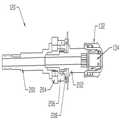
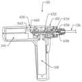
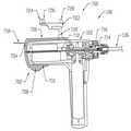
도 3은 예시적 시술도구의 단면도이다.
도 4는 예시적 시술도구의 단면도이다.
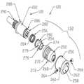
도 5는 시술도구 일부의 사시도이다.
도 6a는 시술도구 방향선택조립체의 사시도이다.
도 6b는 시술도구 역구동-방지 조립체 및 방향선택조립체의 사시도이다.
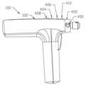
도 7은 대표적 시술도구의 측면도이다.
도 8은 대표적 NIM 부재를 포함한 대표적 시술도구 일부의 측면도이다.
도 10은 대표적 NIM 부재를 포함한 시술도구의 단면도이다.
도 11은 또 다른 대표적 NIM 부재를 포함한 시술도구의 단면도이다.
도 12는 항법 가능 부재를 포함한 시술도구의 단면도이다.
도 13은 대표적 시술도구 및 신경 통합 검사시스템이 통합된 시스템을 도시한 것이다.
도 14는 대표적 시술도구 및 시술 항법 시스템이 통합된 시스템을 도시한 것이다.
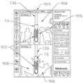
도 15는 화면에 생성된 대표적 방사선 영상을 도시한 NAV 소프트웨어 어플리케이션의 대표적 그래픽 사용자 인터페이스를 보인다.The drawings are not necessarily to scale, the emphasis is placed on showing the principles of the invention. Also, in the drawings, like reference numerals designate corresponding parts throughout the different views.
1 is a side view of a portion of the spine.
2 is a plan view of the spine.
3 is a cross-sectional view of an exemplary surgical tool.
4 is a cross-sectional view of an exemplary surgical tool.
5 is a perspective view of a part of the treatment tool.
6A is a perspective view of a surgical tool direction selection assembly.
6B is a perspective view of the surgical tool backdrive prevention assembly and the orientation selection assembly.
7 is a side view of a typical treatment tool.
8 is a side view of a portion of a representative treatment tool including a representative NIM member.
10 is a cross-sectional view of a surgical tool including a representative NIM member.
11 is a cross-sectional view of a surgical tool including another representative NIM member.
12 is a cross-sectional view of a surgical tool including a navigable member.
FIG. 13 illustrates a system in which a representative treatment tool and a neural integration test system are integrated.
FIG. 14 illustrates a system incorporating a representative surgical tool and a surgical navigation system.
15 shows a representative graphical user interface of a NAV software application showing a representative radiographic image generated on a screen.
본 발명의 원리에 대한 이해를 돕기 위하여, 도면에 도시된 예들이 참조되며, 이를 기술하기 위하여 특정 용어들이 사용된다. 그러나 이에 따라 본 발명의 범위를 제한하는 것이 아니라는 것을 이해하여야 한다. 도시된 기구들 및 기술된 방법에서의 임의적인 변경 및 추가 변형, 및 본원에 기재된 본 발명의 원리에 대한 임의적 추가 적용 역시 본 발명과 관련된 분야에서의 전문가에게 통상 착상될 수 있는 것으로 고려된다.To help understand the principles of the present invention, reference is made to the examples shown in the drawings, in which specific terms are used. It is to be understood, however, that the intention is not to limit the scope of the invention. It is contemplated that any modifications and additional variations in the illustrated apparatuses and methods described, and any additional application to the principles of the invention described herein, may also be commonly conceived to those skilled in the art related to the invention.
도 1을 참조하면, 도면부호 (10)으로 표기된 척주 일부가 도시된다. 도시된 바와 같이, 척주(10)는 허리 영역(12), 엉치 영역(14), 및 꼬리 영역(16)을 포함한다. 또한 척주(10)는 목 및 가슴 영역을 포함한다. 논의를 명료하고 용이하게 하기 위하여, 목 영역 및 가슴 영역은 도시되지 않는다. 허리 영역(12)은 제1허리 척추뼈(18), 제2허리 척추뼈(20), 제3허리 척추뼈(22), 제4허리 척추뼈(24), 및 제5허리 척추뼈(26)를 포함한다. 엉치 영역(14)은 엉치뼈(28)를 포함한다. 또한 꼬리 영역(16)은 꼬리뼈(30)를 포함한다.Referring to FIG. 1, a portion of the spinal column, indicated by
도 1에 도시된 바와 같이, 제1추간 허리 디스크(32)는 제1허리 척추뼈(18)와 제2허리 척추뼈(20) 사이에 놓인다. 제2추간 허리 디스크(34)는 제2허리 척추뼈(20)와 제3허리 척추뼈(22) 사이에 놓인다. 제3추간 허리 디스크(36)는 제3허리 척추뼈(22)와 제4허리 척추뼈(24) 사이에 놓인다. 제4추간 허리 디스크(38)는 제4허리 척추뼈(24)와 제5허리 척추뼈(26) 사이에 놓인다. 또한 제5추간 허리 디스크(40)는 제5허리 척추뼈(26)와 엉치뼈(28) 사이에 놓인다.As shown in FIG. 1, the first intervertebral
도 2를 참조하면, 각 척추뼈 평면도가 도시된다. 도시된 바와 같이, 아래 척추뼈(52)의 척추뼈 몸체(50)는 피질뼈로 이루어진 피질테(54)를 포함한다. 또한, 척추뼈 몸체(50)는 피질테(54) 내부에 해면뼈(56)를 포함한다. 피질테(54)는 때로 견인골단테 또는 견인골단고리로 불린다. 또한 해면뼈(56)는 피질테(54)의 피질뼈보다 대체로 더욱 유연하다.Referring to FIG. 2, a plan view of each vertebra is shown. As shown, the
도 2에 도시된 바와 같이, 아래 척추뼈(52)는 제1뿌리(58), 제2뿌리(60), 제1판(62), 및 제2판(64)을 포함한다. 또한 척추뼈 구멍(66)이 아래 척추뼈(52) 내부에 형성된다. 척수(68)는 척추뼈 구멍(66)을 통과한다. 또한 제1신경뿌리(70) 및 제2신경뿌리(72)는 척수(68)로부터 연장된다. 특히, 제1뿌리(58) 및 제2뿌리(72)는 외과의사가 앵커 및 로드 시스템을 척추에 부착하기 위한 뼈나사와 같은 앵커(73)를 이식하기 위하여 자주 선택하는 척추 영역을 나타낸다. 특히, 척수(68) 및 기타 중요한 해부학적 부위에 인접한 것을 감안하면, 이러한 나사 이식은 세심하고도 정밀한 시술이며 일반적으로 널리 사용되는 것과는 상당히 다른 도구들이 필요하다.As shown in FIG. 2, the
척주를 이루는 척추뼈들은 척주 목 영역에서 허리 영역에 이르기까지 약간 다른 형태를 가진다. 그러나, 제1 및 제2 목 척추뼈를 제외하고 모든 척추뼈가 동일한 기본 구조를 가지며, 즉 이들 구조는 도 2와 함께 상기에 기술된 구조이다. 제1 및 제2 목 척추뼈는 두개골을 지탱하기 위하여 나머지 척추뼈와는 구조적으로 다르다.The spinal vertebrae that form the spinal column have slightly different forms, ranging from the spinal neck region to the lumbar region. However, all of the vertebrae except for the first and second neck vertebrae have the same basic structure, ie these structures are those described above in conjunction with FIG. The first and second neck vertebrae are structurally different from the rest of the vertebrae to support the skull.
도 3-19는 본원에 의한 시술도구(100) 또는 그의 일부를 도시한다. 특히, 도 3-19는 뼈에 또는 뼈 사이 공간 예를 들어 척추뼈 사이에 정형외과용 앵커, 추간 몸체 예를 들어 나사식 케이지 및 나사를 부착시키기 위한 시술도구(100)를 도시한다. 뼈 내부에 안내공을 형성하기 위한 탭퍼 비트 헤드를 이용하는 것을 포함하여 시술도구(100)는 뼈를 탭핑하기에 적합하다. 또한, 시술도구(100)는 나사드라이버 비트 헤드를 이용하여 나사를 뼈에 박기에 특히 적합하다. 시술도구(100)는 시술도구(100)의 전력을 이용하여 뼈 속으로의 초기 나사박기를 촉진시키고, 이후 선택적으로, 촉감 및 래칫 작동(racheting capability)이 더 양호하므로, 수동으로 시술도구(100)를 이용하여 나사 박기 과정을 마무리할 수 있다.3-19 show the
도 3을 참조하면, 시술도구(100) 단면도가 도시되며 이는 근위단(104)에서 반대측 원위단(106)에 걸쳐있는 하우징(102)을 포함한다. 시술도구(100) 작동과 관련하여, 하우징(102)은 핸들(110) 내부에 배치되고 하우징(102)과 체결된 모터(108)를 포함한다. 격발기구(112)가 핸들(110)에 체결되며 모터(108)와 전기적으로 연결되어 사용자가 격발기구(112)를 누르면, 모터(108)는 시술기구(136)를 회전시킨다. 시술기구(136)는 드릴, 탭, 프로브, 구동기구, 예를 들면 소켓, 나사드라이버, 키형 드라이버 (예를 들면- 육각머리드라이버, 별 모양 머리드라이버, 사각머리드라이버 등), 기구(136) 및 이식체(73) 조합, 시술도구(100)에 분리 가능하게 연결할 수 있는 이식체(73), 또는 기타 임의 유형의 시술 도중 회전이 요망되는 시술기구를 포함할 수 있다.Referring to FIG. 3, a cross-sectional view of the
모터(108)는 이로부터 연장되고 전달기구(116)와 체결된 구동축(114)을 포함한다. 하나의 예에서, 전달기구(116)는 베벨기어를 포함한다. 또한, 다른 예에서, 전달기구(116)는 제2베벨기어를 포함하는 제2전달기구(118)와 체결될 수 있고, 이는 다시 출력축(120)과 체결된다. 따라서 격발기구(112)의 체결은 전달기구(116)를 회전시키고 이에 따라 제2전달기구(118)를 회전시키는 모터(108)의 체결을 포함하고, 이로써 출력축(120)을 회전시키케 된다. 따라서, 시술도구(100)는 작업편에 회전력을 제공할 수 있다.The
기타 예시에서 추가로 도시된 바와 같이, 출력축(120)은 출력축 원위부(122)와 연결되는 출력축 근위부(120)를 포함한 여러 부분들로 분할될 수 있다. 하우징(102)은 이로부터 각을 이루어 연장되며 근위단(104)과 원위단(106) 사이에 체결되는 핸들(110)에 연결된다. 일 예에서, 핸들(110) 축(126)과 하우징(102) 축(128) 사이에 실질적으로 수직 각도(124)를 이루며 핸들(110)은 하우징(102)에서 연장된다. 다른 예에 의하면, 각도(124)는 비-수직 각도일 수 있어 핸들(110)은 하우징(102)에 대하여 경사를 이룰 수 있다. 따라서, 실질적으로 비-수직인 각도(124)를 활용하는 예에서, 핸들(110)은 전방 경사 디자인을 가지며, 핸들(110)의 근위단(130)은 하우징(102)의 원위단(106)을 향하여 경사를 이룬다.As further shown in other examples, the
시술도구(100)는 원위단(106)에서 하우징(102)에 체결되는 가동성 척(132)을 포함한다. 일 예에 의하면, 척(132)은 시술기구(136)의 축과 맞물리도록 구성된 개구(134)를 포함한다. 다른 예에서, 척(132)은 스냅-피트 연결을 통하여 시술기구(136) 근위단과 체결되도록 구성된 신속-연결 어댑터를 포함한다. 이러한 신속-연결 어댑터는 스냅-피트 또는 신속-연결 체결을 이루기 위한 편향부재 또는 베어링 수용 채널을 포함할 수 있다는 것을 이해할 수 있다. 하나의 대표적인 예에서, 시술도구(100)는 원위단(106)에서 근위단(104)까지 하우징(102)을 관통하는 경로(138)를 포함한다. 도시된 바와 같이, 경로(138)는 출력축(120) 내부 및 배터리 팩(140) 내부를 관통 연장되고 근위단(104)에 인접한 개구(142)에서 하우징(102)을 빠져나갈 수 있다. 경로(138)는 대체로 소정 직경의 원형 단면 윤곽을 가질 수 있다.The
일 예에서, 경로(138)는 분할되고 두 개의 이격 경로 부분들을 포함하며 이는 출력축(120) 내부에 배치되는 제1부분(150) 및 배터리 팩(140) 내부를 관통하는 제2부분(152)을 포함하고, 제1부분(150) 및 제2부분(152)은 축 방향으로 개구(154)에 의해 분리된다. 경로(138)가 제1부분(150) 및 제2부분(152)을 포함하여 분할되지만, 세 부분, 또는 그 이상의 부분들로 추가로 분할될 수 있다는 것을 이해하여야 한다. 다른 예에 의하면, 경로(138)는 근위단(104)과 원위단(106) 사이의 하우징(102) 전체 길이를 따라 연장되며 임의 개구를 가지지 않는 단일 밀폐 경로이다. 또 다른 예에 의하면, 경로는 달리 설계될 수 있다. 예를 들면, 하나의 예에서 경로(138)는 실질적으로 길이방향 길이를 따라 연장되는 개구를 포함하는 채널일 수 있다. 다른 예에서 경로(138)는 길이를 따라 연장되는 일련의 개구들 또는 천공들을 포함한다.In one example,
다른 예에 따르면, 경로(138)는 경로(138)의 내면을 따라 연장되고 경로(138) 일부에서 연장되는 전기 절연 라이너(160)를 포함할 수 있다. 전기 절연 라이너(160)로 인하여 경로(138)와 하우징(102) 내부에 포함된 주변 부품들 사이의 전기 절연을 용이하게 할 수 있다. 전기 절연 라이너(160)는 경로(138) 길이 일부에서만 연장될 수 있다. 경로(138)가 분할된 예에 있어서, 부분들 중 하나는 전기 절연 라이너(160)를 포함할 수 있고, 한편 제2부분은 전기 절연 라이너(160)를 포함하지 않는다. 예를 들면, 도 3에 도시된 바와 같이, 제1부분(150)은 전기 절연부(160)를 포함하나 경로(138)의 제2부분(152)은 전기 절연 라이너(160)를 포함하지 않는다. 그러나, 배터리 팩(140)을 관통하는 경로(138)의 최소 일부는 전기 절연 라이너(160)를 포함하는 것이 특히 적합하다.According to another example, the
전기 절연 라이너(160)를 형성함에 적합한 재료는 포괄적으로는 유전체 재료를 포함한다. 다양한 유전체 재료로는 세라믹 또는 고분자가 포함된다. 특정 예에 따르면, 전기 절연 라이너(160)는 고분자 재료를 포함한다. 일 예에서, 적합한 고분자 재료는 폴리우레탄, 폴리올레핀, 폴리에테르, 실리콘, 또는 이들의 조합물을 포함한다. 또한, 폴리올레핀 재료는 폴리프로필렌, 폴리에틸렌, 할로겐화 폴리올레핀, 플루오로폴리올레핀, 또는 이들의 조합물을 포함한다. 폴리에테르 재료는 폴리에테르케톤(PEK), 폴리에테르에테르케톤(PEEK), 폴리에테르케톤케톤(PEKK), 폴리아릴에테르케톤(PAEK), 또는 이들의 조합물을 포함한다.Suitable materials for forming the electrically insulating
시술도구(100) 살균을 감안하면, 하우징(102) 및 이에 포함된 부품들은 가압 멸균 가능한 재료로 제조될 수 있다. 본원에서, 가압멸균재료는 121℃ 이상의 온도 및 15 PSIA 이상의 압력에 견딜 수 있는 재료를 포함한다. 본원에서, 일 예에 의하면, 적합한 가압멸균재료는 금속, 금속합금, 또는 고분자를 포함한다. 일 예에 의하면, 하우징(102) 및 그의 내부에 포함된 부품들은 금속 예를 들어 티타늄, 알루미늄, 마그네슘, 철, 코발트, 니켈, 텅스텐, 강, 또는 이들의 조합물을 포함할 수 있다. 더욱 특정한 예에서, 소정 부품들은 고분자 재료로 제조될 수 있고, 예를 들면 폴리우레탄, 폴리올레핀, 폴리에테르, 실리콘, 또는 이들의 조합물을 포함한다. 또한, 폴리올레핀 재료는 폴리프로필렌, 폴리에틸렌, 할로겐화 폴리올레핀, 플루오로폴리올레핀, 또는 이들의 조합물을 포함한다. 폴리에테르 재료는 폴리에테르케톤(PEK), 폴리에테르에테르케톤(PEEK), 폴리에테르케톤케톤(PEKK), 폴리아릴에테르케톤(PAEK), 또는 이들의 조합물을 포함한다. 기타 적합한 재료로는 스틸렌 (예를 들면, 아크릴로니트릴 부타디엔 스틸렌), 폴리카보네이트, 폴리술폰, 및 탄소섬유, 예를 들면 탄소 섬유-강화 복합재료를 포함한다.In consideration of sterilizing the
다른 예를 참조하면, 하우징(102) 일부는 전자기 차폐를 포함한다. 일 예에서, 전자기 차폐는 하우징(102) 내부에 있는 특정 부품들 주위에 배치된 금속망을 포함한다. 배터리 팩(140) 및 모터(108)는 외면의 최소 일부 주위에 제공되는, 및 더욱 상세하게는 외면을 실질적으로 둘러싸는 전자기 차폐를 포함한다. 부품들 특히 배터리 팩(140) 및 모터(108)의 전자기 차폐로 인하여 수술실과 같이 많은 전기기계들이 사용되고 전자기 간섭이 발생될 수 있는 환경에서 시술도구(100)를 효율적이고도 믿을 수 있게 사용할 수 있다.Referring to another example, some of the
다른 특정 예에서, 시술도구(100)는 사용자에 의해 선택될 수 있는 토크 리미터(170)를 추가로 포함할 수 있다. 일 예에 의하면, 시술도구(100)는 메모리를 가지는 마이크로프로세서를 포함하고 전기적으로 모터(108) 및 배터리 팩(140)에 연결되는 제어유닛(180)을 포함하며, 마이크로프로세서(180)는 배터리(140)에서 모터(108)로의 전류를 제어하여, 이에 따라 모터(108) 토크 출력을 제어한다. 토크 리미터(170)는 제어유닛(180)과 연결되어 모터(108) 토크 출력을 가변적으로 조절한다. 다른 예에 의하면, 시술도구(100)는 모터(108) 및 출력축(120)과 체결된 기계적 토크 리미터를 포함한다. 이러한 적합 토크 리미터는 베어링 및 클러치를 포함하며 특정 토크가 초과되면 출력축(120) 제1부분은 출력축(120) 제2부분에서 분리된다.In another particular example, the
도 4를 참조하면, 대표적인 예에 의한 시술도구(100)의 출력축(120) 단면이 제공된다. 도시된 바와 같이, 출력축(120)은 분할되며 근위부(200)는 원위부(202)와 체결된다. 특정 예에 의하면, 출력축(120)의 근위부(200)는 잼 고리(204)를 통하여 원위부(202)와 체결되며, 잼 고리는 래칫기구(206)와 체결되고, 이는 다시 일 부재(208)와 체결된다. 이러한 부품 조합은 다음 도면들에서 더욱 상세하게 기술되며 이들 부품(즉, 도면부호(204), (206) 및 (208)) 조합으로 인하여 출력축(120) 회전운동과 같은 래칫 회전은 정밀하게 제어되고 이는 외과시술에 특히 적합하다.4, a cross section of the
도 5는 도 4에 이미 도시된 출력축(120)의 사시도이다. 도 5를 참조하면, 대표적인 예에 의한 시술도구(100)의 출력축(120) 원위부 사시도가 도시된다. 도시된 바와 같이, 시술도구(100)는 외부 슬리브(250)를 가지는 척(132)을 포함하며, 외부 슬리브는 중간 슬리브(252)와 체결되고, 중간 슬리브는 다시 내부 슬리브(254)와 체결되며, 내부 슬리브는 다시 편향부재(256)와 체결된다. 외부 슬리브(250)는 척(132) 외면을 구성하며 중간 슬리브(252) 및 내부 슬리브(254)를 수용한다. 도시된 바와 같이, 외부 슬리브(250)는 중간 슬리브(252)가 연장되도록 구성된 개구(258)를 포함하며, 이를 통하여 시술기구(136)와 체결된다. 외부 슬리브(250)는 나사들(264, 266)과 체결되도록 구성된 개구들(260, 262)을 포함하며, 나사들은 외부 슬리브(250), 중간 슬리브(252), 및 내부 슬리브(254)를 체결하도록 구성된다.FIG. 5 is a perspective view of the
척(132)의 중간 슬리브(252)는 개구(268)를 포함하며 이는 외부 슬리브(250)의 개구(258)를 관통하여 연장되고 시술기구(136)와 체결되도록 구성된다. 중간 슬리브(252)는 외부 슬리브(250)의 내면 일부 내에서 활주하고 이와 맞물리도록 구성된다. 또한 중간 슬리브(252)는 길이를 따라 축 방향으로 위치되어 나사들(264, 266)과 체결되도록 구성된 개구(270)를 포함하며, 이에 따라 중간 슬리브(252)는 외부 슬리브(250)와 체결될 수 있다. 또한 중간 슬리브(252)는 코일 스프링과 같은 편향부재(272)를 포함하고, 이는 외부 슬리브(250)의 내면과 체결되어 외부 슬리브(250)를 중간 슬리브(252)에 대하여 편향시키도록 구성된다.The
척(132)은 내부 슬리브(254)를 추가로 포함하며, 이는 중간 슬리브(252)에 내면이 맞물리도록 구성된다. 도시 예에 의하면, 내부 슬리브(254)는 개구(274)를 포함하며, 이는 개구(268)를 내부 슬리브(254), 외부 슬리브(250)의 개구(258)와 정렬하도록 구성하여 시술기구(136)를 수용하도록 구성된다. 특정 예에 의하면, 내부 슬리브(254)는 개구(276)들을 포함하며, 이는 신속-연결 체결을 위하여 시술기구(136)를 따라 있는 내부 슬리브 칼라(278) 주위 원주 방향으로 이격 형성된다. 또한 내부 슬리브(254)는 채널 영역(280)을 포함하며 이는 내부 슬리브(254) 외면 주위 원주 방향으로 연장되며 나사들(264, 266)과 체결되도록 구성되어, 내부 슬리브(254)가 중간 슬리브(252) 및 더 나아가 외부 슬리브(250) 내부로 고정 부착된다.The
척(132)은 코일 스프링과 같은 편향부재(256)를 추가로 포함하며, 이는 출력축(120)의 원위부(202) 전면과 내부 슬리브(254) 후면 사이에 체결하도록 구성된다. 편향부재(256)로 인하여 출력축(120)의 원위부(202) 일 면(282)을 향하여 내부 슬리브(254)를 축 방향으로 누르면 척(132)에서 비트 축이 분리될 수 있어 한 손으로 시술기구(136)를 분리할 수 있다.The
출력축(120)의 원위부(202)는 개구(284)를 포함하며, 이는 시술기구(136) 일부를 수용하도록 구성된다. 도시된 바와 같이, 개구(284)는 비트 축 근위단과 체결되도록 구성된 단면 윤곽을 가지며 예를 들면 도시된 바와 같이 육각 단면 윤곽을 가진다. 또한 출력축(120)의 원위부(202)는 나사부(286)를 포함하며 이는 내부 슬리브(252) 내면에 있는 나사와 체결되어 척(132)을 출력축(120)의 원위부(202) 단부에 고정적으로 체결할 수 있도록 구성된다. 다른 예에 의하면, 출력축(120)의 원위부(202)는 립(288)을 포함하며 이는 도 6a에 추가로 도시된 부품들과 맞물리고 직접 접촉되도록 구성된다.
출력축(120)의 원위부(202)는 외면 원주 주위로 연장되는 치형 표면(290)을 포함하며 이는 도 6b에서 추가로 도시된 부품들과 체결되도록 구성된다. 특히, 치(teeth)(290)로 인하여 래칫기구 (참조 도 6b) 체결을 정밀하게 제어할 수 있다. 따라서 일 예에서 치형 표면(290)은 원위부(202)의 원주 주위로 연장되는 최소한 총 20개의 치를 포함한다. 특정 예에서, 치형 표면(290)은 총 약 30개 내지 50개의 치를 포함한다. 이러한 총 개수의 치를 가지는 치형 표면(290)으로 인하여 정밀한 래칫제어가 가능하며 이는 특히 외과 시술 중 사용에 적합하다.The
도 6a 및 6b는 대표적인 예에 따른 시술도구(100)에 사용되는 출력축(120) 일부에 대한 사시도이다. 개략적으로, 도 6a는 정방향 및 역방향 구동 위치 선택을 위한 방향선택조립체(300)를 도시한 것이다. 도 6b는 개략적으로 래칫기구 및 역구동-방지조립체 부품들을 도시한 것이다. 도 6a를 참조하면, 슬리브(302)는 핀들(308, 310)과 체결되도록 구성된 개구들(304, 306)을 가진다. 방향선택조립체(300)는 슬리브(302) 내부에 배치되며 슬리브(302) 내부 립(314)에 접촉되도록 구성된 부재(312)를 추가로 포함한다. 부재(312)는 후면에서 돌출되어 도 6b에 도시된 역구동-방지기구와 체결되도록 구성된 하나 이상의 돌기 또는 핀을 추가로 포함한다. 일 예에서, 부재(312)의 핀(316)은 역구동-방지기구 내부 개구와 체결되도록 구성되어, 클러치로 작용하며 역구동-방지기구 내부의 멈춤쇠(도 6b에 도시)를 특정 위치에서 잠글 수 있다.6A and 6B are perspective views of a portion of the
부재(312)는 핀(316)보다 길이가 더 짧은 하나 이상의 핀(318)을 포함하며, 이는 특히 역구동-방지기구 내부 개구들과 선택적으로 체결되도록 구성되어 래칫기구를 체결 또는 분리시킨다. 하나의 특정 예에 의하면, 부재(312)는 부재(312) 후면에서 돌출되는 동일한 길이의 3개의 핀(316) 및 더 짧은 길이의 3 개의 핀 예를 들어 핀(318)을 포함한다.The
도 6a에 도시된 바와 같이, 방향선택조립체(300)는 슬리브(320)를 추가로 포함하며, 이는 몸체 폭을 관통하는 개구들(322, 324)을 가진다. 슬리브(320)는 슬리브(302) 내경 내부에 맞추어지고 부재(312)를 슬리브(302) 내부에 고정시키도록 구성된다. 일 예에 의하면, 부재(312)는 슬리브(302) 내부에서 일반적으로 자유롭게 회전될 수 있다. 또한 개구들(322, 324)은 핀들(308, 310)과 체결되도록 구성되며 핀들(308, 310)은 개구들(322, 324)을 관통하여 슬리브(320) 내면과 수평을 이룬다.As shown in FIG. 6A, the
일 예에 의하면, 핀들(308, 310)은 하우징(102) 내면을 따라 형성된 채널 또는 슬롯(도 3에서 도면부호(330) 및 (332))과 체결되도록 구성된다. 핀들(308, 310)은 채널 내부에서 자유 활주할 수 있고 핀들(308, 310)의 일 위치에서 다른 위치로의 이동으로, 부재(312) 핀(318)은 역구동-방지기구에 있는 개구와 체결 또는 분리되고 따라서 래칫기구 작동을 선택하거나 선택을 해제할 수 있다. 다른 예에 의하면, 핀들(308, 310)은 하우징(102)에 맞추어진 캡 안쪽의 캠 슬롯들 내부에서 맞물려져 방향선택제어를 용이하게 할 수 있다.In one example, the
도 6b는 역구동-방지조립체(350) 및 방향선택조립체(300) 부품들의 사시도이다. 도시된 바와 같이, 역구동-방지조립체(350)는 방향선택조립체(300)와 체결되도록 구성된다. 역구동-방지조립체(350)는 역구동-방지기구(352)를 포함하며, 이는 개구들(354, 356)을 포함하고 이는 각각 방향선택조립체(300) 핀들(316, 318)과 소정의 상황에서 체결되도록 구성된다. 역구동-방지기구(352)는 개구들(358, 360, 362)을 추가로 포함하며, 이는 멈춤쇠(364, 366, 368) 및 각 상응 편향부재(370, 372, 374)를 수용한다. 특정 예에 있어서, 역구동-방지기구(352) 래칫 작동은 각 개구들(358, 360, 362) 내부에 배치되도록 구성된 멈춤쇠(364, 366, 368)에 의해 가능하다. 또한, 일 특정 예에 있어서, 편향부재(370, 372, 374)에 의해 멈춤쇠(364-368)는 역구동-방지기구(352) 일부에 대하여 탄성 편향되어 개구로 연장되고 치들 (도 5에서 치들(290)로 도시됨)과 체결된다.FIG. 6B is a perspective view of the reverse drive prevention assembly 350 and the
도 6b에 도시된 바와 같이, 역구동-방지조립체(350)는 잼 고리(376)를 추가로 포함하며, 이는 역구동-방지기구(352) 일면과 체결되도록 구성된다. 또한 도시된 바와 같이, 롤러들(378, 380, 382)은 잼 고리(376) 내면(384)에 배치되고 체결되도록 구성된다. 일 예에서, 출력축(386)의 근위부는 원위면(394)에서 축 방향으로 연장된 암들(388, 390, 392)을 포함하며, 이는 잼 고리(376) 개구(396) 내부로 연장되고 모터(108)가 출력축(386)의 근위부로 토크를 제공할 때 역구동-방지기구 일부와 체결되도록 구성된다. 암들(388-394) 및 역구동-방지기구(352) 일부 간 체결로 인하여, 모터(108)가 토크를 제공할 때, 출력축(386)의 근위부로부터 출력축(202)의 원위부 (도 5 참조)로 토크 전달이 가능하다. 이와 달리, 토크가 출력축(202)의 원위부로부터 근위부로 인가될 때 (즉, 모터로부터가 아닌), 잼 고리(376)로 인하여 모터(108)는 출력축(202)으로부터 분리되어 모터(108) 손상이 방지된다. 특히, 토크가 모터(108) 반대측에서 일부에 인가될 때, 롤러들(378-382)은 잼 고리(376) 내면에 대하여 잠기고 출력축(202)의 원위부는 근위부로부터 해제된다.As shown in FIG. 6B, the reverse drive prevention assembly 350 further includes a
모터(108) 힘에 의해 시술도구(100)가 정방향 작동되면, 핀들(308, 310)은 하우징 내부에 있는 슬롯 또는 채널에서 이동되고 부재(312) 핀(318)은 역구동-방지기구(352)의 개구(356)에서 해제된다. 출력축(386)의 근위부는 시계 방향으로 회전하고 암들(390-394)은 역구동-방지기구(352) 면들과 체결 및 접촉하며, 롤러들(628-630)은 잼 고리(376) 내면(384) 내부에서 자유로이 회전한다. 회전운동은 출력축(202)의 원위부로 전달되고 이는 회전되며 멈춤쇠(364-368)는 토크를 전달하는 치형 표면(290)의 치들과 체결된다.When the
시술도구(100)는 사용자에 의해 선택되거나 제조업자에 의해 조립체에 설정된 특정 토크까지 수동으로 정방향 작동될 수 있다. 정방향 수동 작동되는 동안, 특정 토크가 초과되면 출력축(386)은 역방향 또는 역구동 회전된다. 특정 토크를 넘으면, 출력축(386)의 근위부는 암들(390-394) 및 롤러들(378-382)이 잼 고리(376) 내면(384)에 잠길 때까지 짧은 거리 회전을 역전시킬 수 있다. 일 예에 의하면, 잼 고리(376)가 도구(100) 하우징(102)에 대하여 잠기므로, 역구동은 정지되고 출력축의 수동 정방향 구동은 계속될 수 있다. 이 경우, 전력으로 시술도구(100)가 정방향 작동될 때 멈춤쇠들이 통상 그러하듯 멈춤쇠(364-368)는 치형 표면(290) 치들과 자유로이 체결될 수 있다는 것을 이해하여야 한다.The
시술도구(100)는 모터(108) 또는 수동으로 역방향 작동될 수 있다. 방향선택조립체를 사용하여 특히 하우징 내부 채널에서 핀들(308, 310)의 위치를 변경시켜 역방향을 선택할 수 있다. 핀들(308, 310)의 위치를 변경시키면, 부재(312) 핀(318)은 역구동-방지기구(352) 개구(356) 내부에 체결되어, 멈춤쇠(364-368)는 고정되거나 또는 체결된 위치에서 치형 표면(290)과 잠김으로 이들은 튕겨지지(flip) 않는다. 개구(356) 내부에 핀(318)을 체결시키므로 래칫작동은 없어진다. 따라서, 일 예에서, 전력으로 시술도구(100)가 역방향 동작될 때, 멈춤쇠(364-368) 및 핀(318)의 체결을 통하여 암들(388-392)은 토크를 역구동-방지기구(352) 핀(318)에 직접 전달한다. 또한, 특정 예에 의하면, 역방향에서 래칫기능은 없다.The
도 7은 대표적인 예에 의한 시술도구(100)의 측면도를 도시한 것이다. 시술도구(100)는 스위치(400)를 포함하며, 이는 하우징(102)에 연결되고 전기적으로 모터(108)에 연결된다. 스위치(400)는 모터(108) 정방향 작동 위치 및 역방향 작동 위치에 해당되는 제1 위치와 제2 위치 사이에서 움직일 수 있다. 다른 특정 예에서, 스위치(400)는 칼라(402)에 부착되며, 이들 모두는 모터(108) 정방향 작동 조건 및 역방향 작동 조건을 선택하기 위하여 하우징(102) 원주 주위로 이동될 수 있다. 일 특정 예에 의하면, 스위치(400) 및 모터(108)의 전기적 연결은 정방향 전기 스위치 및 역방향 전기스위치의 연동(gang)을 포함하여, 모터(108) 방향을 변경시키기 위하여 양쪽 모두가 조작되어야 한다. 이러한 조합을 통하여 소정의 안전 제어가 가능하며, 이는 시술도구 사용에 적합하다.Figure 7 shows a side view of the
다른 예에 의하면, 스위치(400)는 중립위치를 포함할 수 있다. 대체로, 스위치(400) 중립위치는 모터(108) 전력 중단을 포함하며, 이에 따라 시술도구(100)는 수동 래칫 과정에 적합하게 된다. 다른 예에 의하면, 스위치(400)는 중립 위치를 포함하며, 이때 출력축은 래칫 위치에서 해제된다.As another example, the
시술도구(100)는 사용자에게 시술도구(100) 상태를 보이기 위한 제1광학 표시기(404)를 추가로 포함할 수 있다. 예를 들면, 일 특정 예에서 광학 표시기(404)는 도구 전원 (즉, 배터리 팩 140) 및 스위치(400)와 전기적으로 연결되어 모터(108)의 정방향 또는 역방향 상태를 표시하도록 구성될 수 있다. 특정 예에 의하면, 스위치(400)가 모터(108) 정방향 회전을 선택할 때 광학 표시기 (404)가 출력을 표시하고, 스위치(400)가 모터(108) 역방향 회전을 선택할 때 제2광학 표시기(406)가 출력을 표시한다. 적합한 광학 표시기로는 빛 예를 들면 LED 빛 등을 포함한다. 더욱 상세하게, 광학 표시기(404, 406)는 다른 광학적 특성 예를 들면 색을 가질 수 있어 조작자가 스위치(400) 위치 및 모터(108) 구동 방향을 확인하기에 적합하다. 이해되는 바와 같이, 중립위치를 가지는 스위치(400)를 사용하는 예에서, 광학 표시기는 스위치(400)의 그 위치에 연결되거나 또는 이와 달리 광학 표시기(404, 406) 어떤 것도 모터(108)가 중립위치에 있으면 출력을 표시하지 않는다.The
다른 예에 의하면, 시술도구(100)는 사용자에게 도구 상태를 전달하도록 구성된 가청 표시기(408)를 포함할 수 있다. 이러한 예에서, 가청 표시기(408)는 제어유닛(180) (도 3 참조)에 연결된 스피커를 포함한다. 하기에 상세하게 개시되는 바와 같이, 가청 표시기(408)는 외과시술 도중 가청 경고 및 지시를 생성할 수 있다. 또한, 시술도구(100)는 제어유닛(180)과 연결된 제3의 광학 표시기(410)를 포함할 수 있다. 하기에 상세하게 개시되는 바와 같이, 광학 표시기(410)는 외과시술 도중 외과의사에게 가시적 경고를 생성할 수 있다. 다른 예에서, 하기에 더욱 상세하게 기재되는 바와 같이, 요소들(404, 406)은 두 개의 버튼들로 구성되며, 이는 시술기구(136)에 공급되는 신경자극신호 강도를 조절하기 위한 신경신호조절부재(854) (도 13 참고)를 포함한다.As another example, the
도 8-12는 신경통합검사(NIM) 시스템(802) (도 13 참고)과 결합된 본원의 도구(100)를 도시한다. 대체로, NIM 시스템은 특정 시술과정 동안 환자의 신경상태를 검사하기 위하여 사용된다. 예를 들면, 신경계에서 극히 중요한 요소인 척수가 시술부위에 아주 인접한 척추시술이 이루어지는 동안, NIM 시스템을 사용하여 외과의사는 소정 척추시술로 인하여 생길 수 있는 신경계 변화를 검사하고 손상을 피한다. 예를 들면, 특정한 경우, 외과의사는 소정의 이식체를 위하여 척주 뿌리에 앵커를 박을 수 있다. 이러한 앵커 배치는 척수를 간섭하지 않아야 하는 정밀한 작업이므로, 수술실에서 NIM 시스템을 통합함으로써 앵커를 환자에게 박는 동안 외과의사는 환자의 신경상태를 검사하여, 박히는 앵커가 환자 신경계에 악영향을 주지 않는다는 것을 확신하게 된다.8-12 show the
하기 상세하게 개시되는 바와 같이, NIM 시스템은 여러 부품들을 가지지만 크게는 시술하는 동안 환자에게 꽂히는 일련의 전극들, 전기신호 전달도구, 및 도구로부터 전기신호를 수신하고 환자 신경상태를 검사할 수 있는 모니터를 포함한다. 도 8-14에 도시된 바와 같이, 시술도구(100) 디자인 및 사용 용도를 감안하면, 특정 NIM 시스템 통합 디자인은 특히 시술도구(100)와 통합되도록 설계된다.As described in detail below, the NIM system has several components but largely capable of receiving electrical signals from and inspecting patient neurological conditions from a series of electrodes, electrical signaling tools, and tools that plug into the patient during the procedure. Include a monitor. As shown in FIGS. 8-14, given the design and use of the
도 8은 시술도구(100) 일부 및 이에 연결된 NIM 부재 측면도이다. 도 8에 도시된 바와 같이, NIM 부재(500)는 시술도구(100) 하우징(102)에 연결된 베이스 조립체(502)를 포함한다. 일 예에 의하면, NIM 부재(500)는 베이스 조립체(502)에서 연장되고 시술도구(100)의 하우징(102) 상부로 연장되는 암(504)을 추가로 포함한다. 하기에 더욱 상세하게 개시되는 바와 같이, 특정 일 예에서, 베이스 조립체(502)는 전기적 기대신경자극신호를 발생하도록 작동되는 신경신호발생회로(850) (예를 들면 도 13 참고)를 포함한다. 이러한 예에서, 신경자극신호를 형성하기 위한 전력은 배터리 팩(140) 또는 달리 NIM 시스템(802)에서 제공된다.8 is a side view of a portion of the
암(504)은 원위단에 활성조립체(506)를 포함하며, 이는 시술기구(136) 도전부와 전기 접촉되도록 구성된다. 일반적으로, NIM 시스템(802) (도 13 참고)을 사용할 때, 도구 일부, 예를 들면 본 예에서 시술기구(136) 및 NIM 부재(500)는 도전부를 포함하여 시술도구(100)와 NIM 시스템(802) (하기 상세 설명) 간 전기신호 전송을 가능하게 한다. 따라서 본원에 사용되는 활성조립체는 전기적 기대신경자극신호를 시술기구(136)로 전송할 수 있는 NIM 부재(500) 일부를 구성한다.
도 8에 도시된 시술기구(136)는 시술도구(100)로부터 신호를 신경구조체로 전송할 수 있는 도전부를 가지며 이러한 신호는 NIM 시스템(802)에서 감지된다. 본 예에 따라, 활성조립체(506)는 최소한 하나의 전도성 강모 또는 가능한 다수의 전도성 강모를 가지며 시술기구(136) 도전부와 전기적으로 연결되는 브러시(508)를 포함한다. 브러시(508) 및 시술기구(136) 도전부와의 전기접촉으로 인하여 NIM 부재(500) 활성조립체(502)로부터 시술기구(136)로의 신경전기자극신호 전송이 가능하다. 일 예에 의하면, 활성조립체(502)는 전력 공급부에 연결될 수 있는 전력구동요소 및/또는 회로 (예를 들면 신경자극발생회로(850) 참고)를 포함한다. 특정 예에서, 활성조립체(502)는 시술도구(100) 내부에 포함된 배터리 팩(140)과 전기적으로 연결되고 전력이 공급되는 부품들 또는 회로들을 포함한다.The
도 8에는 암(504)에서 연장된 와이어(510)가 도시된다. 특정 예에 의하면, 암(504)은 도전부를 가지며 이는 와이어(510)를 활성조립체(502)와 전기적으로 연결시켜 이를 통하여 전기신호를 전송할 수 있다. 와이어(510)는 NIM 부재(500)를 수술실 내 NIM 시스템(802)에 연결시킨다. 다른 특정 예로 더욱 상세하게 기술되는 바와 같이, NIM 부재(500) 또는 시술도구(100)는 선택적으로 무선 통신할 수 있어 NIM 시스템(802)으로 및 시스템으로부터 신호를 무선 송신 및 수신할 수 있다. 또한 본원에 기재된 모든 NIM 부재 예에서, 유선 또는 무선 연결이 적용되어 활성조립체와 NIM 시스템(802) 사이의 신호 전송이 가능하다는 것을 이해할 것이다.8 shows a
도 9는 시술도구(100) 및 다른 대표적인 예에 의해 연결된 NIM 부재(550) 측면도를 도시한 것이다. 도시된 바와 같이, NIM 부재 (550)는 연결구(554, 556)를 통하여 시술도구(100) 하우징(102)에 연결된 베이스 조립체(552)를 포함한다. 베이스 조립체(552)는 하우징(102) 길이 대부분을 따라 연장되며 특히 외과의사 조준선 수술 방해를 줄이도록 설계된 낮은 형상을 가진다. 하나의 예에서, 연결구(554, 556)는 스냅-피트 또는 마찰 맞춤을 통하여 하우징(102)에 연결된다. 다른 예에서, 연결구(554, 556)는 자석을 통하여 하우징(102)에 연결된다. 이러한 연결구(554, 556)를 사용함으로써 NIM 부재(500) 및 시술도구(100)와의 선택적 연결 및 해제가 가능하다.9 illustrates a side view of a
도시된 바와 같이, NIM 부재(550)는 베이스 조립체(552)에서 하우징(102) 상부로 연장되며 신속-연결 체결되는 암(558)을 포함한다. NIM 부재(550)는 활성조립체(560)를 추가로 포함하며, 이는 암(558) 원위단에 체결되어 활성조립체(560)와 시술기구(136)의 도전부를 전기적으로 연결하도록 구성된다. 특정 예에 의하면, 활성조립체 (560)는 시술기구(136) 원주를 실질적으로 둘러싸도록 시술기구(136)와 연결된다. 다른 예에서, 활성조립체(560)는 시술기구(136) 도전부와 전기 접촉되도록 구성된 시술도구(100)와의 슬립-고리 접촉부를 추가로 포함한다. NIM 부재(550)는 베이스 조립체(552)에서 연장되며 전기적 연결 및 NIM 시스템(802)으로 및 시스템으로부터 신호 전송을 제공하도록 구성된 와이어(562)를 추가로 포함한다. 하기에 상세히 기술되는 바와 같이, 다른 예에서, 시술도구(100)는 NIM 시스템(802)과 무선 통신하도록 구성된다.As shown, the
도 10은 또 다른 대표적인 예에 의한 NIM 부재(600)를 포함하는 시술도구(100) 일부 단면도이다. 상기에 기술한 바와 같이, 시술도구(100)는 경로(602)를 포함하며 이는 대체로 하우징 원위단에서 근위단으로 연장되며 더욱 상세하게는 배터리 팩(140)을 관통한다. NIM 부재(600)는 하우징(102)에 연결된 베이스 조립체(604)를 포함한다. 베이스 조립체(604)는 도전부(606)를 포함하며 이는 시술도구(100) 내부에서 연장되며 더욱 상세하게는 시술도구(100) 내부 경로(602) 최소 일부를 따라 연장된다. 더욱 하기에 기술되는 바와 같이, 베이스 조립체(604)는 신경신호발생회로 또는 유닛(850) (도 13 참조)을 포함하며 이는 기대신경자극신호를 발생하도록 작동된다. 일 예에서, 기대신경자극신호는 배터리 팩(140)에서 제공되는 전력으로 발생되나 다른 예에서 NIM 시스템(802)에 의해 발생되어 와이어(618)를 통하여 베이스 조립체(604)로 전송될 수 있다.10 is a partial cross-sectional view of the
본 예에서, NIM 부재(600)는 활성조립체(608)를 포함하며, 이는 도전부(606)에 연결되고 경로(602) 내부에 배치된다. 활성조립체(608)는 시술기구(136) 도전부에 도전부(606)를 전기적으로 연결하여, 신경신호발생회로(850)에 의해 발생된 기대신경자극신호를 시술기구(136)로 전송한다. 다른 더욱 특정한 예에서, 활성조립체(608)는 경로(602) 내부에 신속-연결 체결부(610)에 접촉 배치되어 시술기구(136)가 신속-연결 체결부(610) 내부에 체결될 때 활성조립체(608)와 시술기구(136) 도전부 사이에 전기적 연결이 형성된다.In this example, the
경로(602) 일부 내부에 배치되는 도전부(606)를 이용하는 예에서, 경로(602) 최소 일부는 전기 절연 라이너 재료를 포함하여 도전부(606) 및 기타 시술도구(100) 내부 전기부품들의 전기적 연결을 방지한다. 또한 전기 라이너는 하우징(102) 내부 모터(108)에 도전부(606)와 활성조립체(608) 사이의 적당한 전자기 차폐를 제공한다. 일반적으로, 도전부(606)를 수용하는 경로(602)의 최소 일부는 전기 절연 라이너를 포함한다. 그러나, 다른 특정 예에서는, 경로(602)의 전체 길이에 전기 라이너가 포함된다. 또 다른 예에서, 더욱 전기적 절연을 위하여 도전부(606)는 외부 주위에 싸인 라이너와 같은 전기 절연부를 포함한다.In an example using a
베이스 조립체(604)는 NIM 부재(600) 작동을 위한 온-상태와 오프-상태 사이로 작동될 수 있는 스위치(612)를 포함한다. 다른 예에서, 스위치(612)는 조절부재를 포함하여, 외과의사는 기대신경자극신호 전류 세기를 증감시킬 수 있다. 베이스 조립체(604)는 외과의사에게 환자의 소정 신경상태를 표시하기에 적합한 예를 들면 가청 표시기 또는 광학 표시기와 같은 표시기(614, 616)를 추가로 포함한다. 예를 들면, 표시기(614)는 LED이고 환자 조건이 정상일 때 표시할 수 있고, 이와 달리 표시기(616)는 LED이고 환자 상태가 변화되거나 비정상일 때 다른 표시를 제공할 수 있다. 따라서 표시기(614, 616)는 외과의사가 정확하고 안전한 외과시술을 하도록 조력한다.The
도시된 바와 같이, NIM 부재(600)는 베이스 조립체(604)에서 연장되어 활성조립체(608)와 수술실내 NIM 시스템(802) 사이에 전기신호를 전송하도록 구성된 와이어(618)를 포함한다. 또한, 다른 예에서, 베이스 조립체(604)는 전원에 연결될 수 있다. 일 특정 예에 의하면, 베이스 조립체(604)는 전기연결부(620)를 통하여 배터리 팩(140)에 전기적으로 연결된다. 베이스 조립체(604)와 배터리 팩(140) 사이 전기연결부가 경로(602) 내부로 연장될 수 있다는 것을 이해할 것이다. 상기에 기술된 바와 같이, 베이스 조립체(604)는 신경신호발생회로(850)를 포함하며, 이는 시술기구(136)에 인가되는 기대신경자극신호를 발생시키도록 작동된다.As shown, the
도 11은 또 다른 예에 따른 NIM 부재(650)가 조합된 시술도구(100)의 단면도이다. 도시된 바와 같이, NIM 부재(650)는 도전부(652)를 포함하며 이는 하우징(102) 내부에 있는 경로(654) 일부 내부에 배치된다. 도시된 바와 같이, NIM 부재(650)는 활성조립체(656)를 추가로 포함하며, 이는 도전부(652)와 전기적으로 연결되며 신속-연결 체결부(658)에 접한 경로(654) 일부 내부에 배치되고 활성조립체(656)를 시술기구(136) 도전부와 연결되도록 구성된다.11 is a cross-sectional view of the
본 특정 예에서, 도전부(652)는 시술도구(100) 하우징(102) 내부에 배치된 제어조립체(660)와 전기적으로 연결된다. 제어조립체(660)는, 도전부(652)로 전송되어 결국 활성조립체(654)에 전송되는 기대신경자극신호를 발생시키도록 구성된다. 또한 제어조립체(660)는 NIM 시스템(802)과의 사이에서 무선으로 신호를 송신 및 수신하도록 구성된다. 제어조립체(660)는 전원에, 더욱 상세하게는 전기연결부(662)를 통하여 배터리 팩(140)으로 연결된다. 제어조립체(660)가 하우징(102) 내부에 배치되는 것으로 도시되지만, 다른 적합한 예에서, 제어조립체(660)는 외장형으로 하우징(102)에 연결된다.In this particular example, the
도 12는 항법 가능 부재(700) 및 NIM 부재(702)와 조합된 시술도구(100)의 단면도이다. 도시된 바와 같이, NIM 부재(702)는 시술도구(100) 하우징(102)에 연결된 상부 암(706) 및 하부 암(708)을 가지는 베이스 조립체(704)를 포함한다. 암(708)은 하우징(102) 하부를 따라 연장되며, 하우징(102) 체결부 또는 내부 함몰부와 체결되도록 구성되어 베이스 조립체(704)를 하우징(102)에 고정 부착시키는 플랜지(710)를 포함한다. NIM 부재(702)는 하우징(102) 근위단에서 하우징(102) 원위단까지 경로(716) 길이를 따라 연장되는 도전부(712) 및 활성조립체(714)를 추가로 포함한다. NIM 부재(702)는 베이스 조립체(704)에서 연장되고 NIM 시스템(802)과 활성조립체(714)를 전기적으로 연결하도록 구성된 와이어(718)를 추가로 포함한다.12 is a cross-sectional view of the
도시된 바와 같이, 시술도구(100)는 베이스 조립체(704)에 더욱 상세하게는 NIM 부재(702) 상부 암(706)에 연결된 항법가능부재(700)를 포함한다. 본 예에 의하면, 항법가능부재(700)는 암(706)에 직접 연결된 베이스(720)를 포함한다. 항법가능부재(700)는 상부(722)를 추가로 포함하고, 이는 반사 구조체(724, 726, 728)를 지지하고, 이들은 수술실에서 검출기에 의해 방사되도록 구성된 적외광을 반사하여 도구(100)의 삼각측량을 가능하게 한다. NIM 부재(702) 및 항법가능부재(700)의 조합으로 인하여 컴퓨터 조력 시술 개선이 가능하고 이에 따라 외과의사는 척추시술과 같이 정밀한 시술 도중 환자의 신경상태를 검사하면도 수술실에서 시술도구(100) 배치 및 배향이 가능하다. 이전 예에서와 같이, NIM 부재(702)는 기대신경자극신호를 시술기구(136)로 전송하기 위하여 도전부(712)와 연결된 신경신호발생회로(850)를 포함할 수 있다.As shown, the
도 13을 참조하면, NIM 시스템(802)과 시술도구(100)를 무선 통합한 시스템(800)이 도시된다. NIM 시스템(802)은 베이스 유닛(804)을 포함하며, 이는 프로세서(806), 메모리(808), 디지털 신호처리기(810), 아날로그 인터페이스 회로(812), 및 송수신기 또는 수신기(814)를 포함한다. 본 예에서, 인터페이스 박스(816)는 아날로그 인터페이스 회로(812)에 연결된다. 도시된 바와 같이, 다수의 전극들(818)이 인터페이스 박스(816)에 연결된다. 다른 예에서, 전극들(818)은 NIM 시스템(802)에 직접 연결되고 특히 아날로그 인터페이스 회로(812)에 직접 연결될 수 있다. 하나의 예에서, 아날로그 인터페이스 회로(812)는 아날로그-디지털 변환기를 포함하며, 이는 전극(818)에서 수신된 아날로그 입력신호를 디지털 신호로 변환할 수 있다.Referring to FIG. 13, illustrated is a
외과시술 도중, 전극들(818)은 환자(819)의 여러 지점들에서 연결되어 시술되는 동안 환자 신호반응을 검사한다. 일 예에서, 전극들(818)은 근전도("EMG"), 즉 시술기구(136)에서 제공되는 신경자극신호에 의한 신경자극으로 일어나는 근육반응을 NIM 시스템(802)으로 전송되는 형태로 판독할 수 있다. 본 예에서, 전극들(818)이 환자 신체 여러 지점들에서 환자와 연결된 후, 전극들(818)은 인터페이스 박스(816)에 연결된다. 전극들(818)은 전형적으로 다수의 감지전극들 및 하나 이상의 접지전극을 포함한다. 인터페이스 박스(816)는 전극들(818)과 베이스 유닛(804) 사이에 전기적 인터페이스를 제공한다. 특히, 전극들(818)은 NIM 시스템(802)에 의해 처리될, 감지된 환자 신경반응에 해당되는 전기신호를 인터페이스 박스(816)로 전달한다.During surgery, the
상기에 기술된 바와 같이, 시술도구(100) 시술기구(136)에는 신경신호발생회로(850)로부터 기대신경자극신호가 제공된다. 예를 들면 척추 시술의 경우, 시술기구(136)가 환자 신경의 소정 인접 구역으로 이동되거나 또는 시술기구(136)가 이식체(73)와 접하면, 기대전기신호에 따라 신경반응이 발생되고 이는 하나 이상의 전극들(818)에 의해 감지된다. 시술기구(136)는 이식체(73)와 같이 전도성이므로, 기대신경자극신호는 시술기구(136) 및/또는 이식체(73) 근처 각 신경요소에 의해 감지될 수 있다. 시술기구(136)는 이식체(73)와 물리적으로 접촉하고 있으므로 시술기구(136)는 신경자극신호를 이식체(73)로 전송한다. NIM 시스템(802)에 의해 감지되는 반응은 하나 이상의 전극들(818)에 의해 감지되는 전기신호 형태이다. 본 신호는 인터페이스 박스(816)로 전송되고, 이는 감지 반응을 다시 NIM 시스템(802)의 아날로그 인터페이스 회로(812)로 전송한다.As described above, the
일 예에서, 아날로그 인터페이스 회로(812)는 감지된 반응을 디지털 신호로 변환할 수 있는 디지털 신호 처리기(810)로 감지된 신호를 조절 및 전송하며 디지털 신호는 프로세서(806)로 다시 전송된다. 다른 예에서, 아날로그 인터페이스 회로(812)는 아날로그-디지털 회로로 구성되며, 이는 아날로그 반응을 디지털 신호로 변환시키고 추가적인 처리를 위하여 디지털 신호 처리기(806)로 전송된다. 이들 예에서, 디지털 신호 형태의 반응은 프로세서(806)로 보내지고 프로세서(806)는 수신 반응에 대하여 적당한 동작을 취할 수 있다.In one example,
프로세서(806)에서 작동하는 NIM 소프트웨어 어플리케이션(820)은 디지털 신호를 처리하도록 구성되고, 무엇보다도, 감지신호를 베이스 유닛(804)과 연결된 화면(822)에 그래픽으로 표시한다. 이와 같이 시술도구(100)의 시술기구(136)는 전기신호를 전달하므로, 시술기구(136) 또는 이식체(73)가 신경요소 소정 거리 내에 위치하면 외과시술 도중 시술도구(100)는 신경반응을 발생시킬 수 있다. 척추시술의 경우, 하기에 기술되는 바와 같이, 이로 인하여 외과의사는 신경요소와의 잠재적 유해 접촉을 피하기 위한 정밀한 결정 및 적합한 조치가 가능하다.The
도 13에 도시된 바와 같이, 본 예에서, 시술도구(100)는 제어유닛(852), 신경신호조절부재(854), 광학 표시기(856), 가청 표시기(858) 및 송수신기(860)를 포함한다. 또한, 일 예에서, 시술도구(100)는 안전정지회로(862)를 포함하며 이는 제어유닛(852) 및 모터(108)와 연결되어 모터(108)를 정지시키도록 작동된다. 다른 예에서, 제어유닛(852)은 모터(108)에 직접 연결되어 모터(108)를 정지시키도록 동작되므로 안전정지회로(862)가 불요하다. 하기에 상세히 개시되는 바와 같이, 시술도구(100)는 안전 정지 특성을 가지도록 구성되어 NIM 시스템(802)이 시술기구(136) 및/또는 이식체(73)가 신호요소에 너무 가까이 또는 근처에 있다는 신경반응을 감지하면 NIM 시스템(802)은 신호를 시술도구(100)에 보내어 모터(108)를 정지시키고 따라서 시술기구(136)의 회전을 정지시킨다.As shown in FIG. 13, in the present example, the
상기에 기술된 바와 같이, 일 예에서 시술도구(100)는 제어유닛(852)을 포함한다. 제어유닛(852)은 마이크로프로세서-기반 유닛, 주문형 반도체("ASIC"), 아날로그 및 디지털 회로 조합, 또는 상기 요소들의 임의 조합을 포함한다. 또한 시술도구(100)의 일부 부품들은 개별 부품들로 도시되나, 하나 이상의 부품들이 제어유닛(852)으로 통합되거나 일부일 수 있다는 것을 알 수 있다. 예를 들면, 제어유닛(852)은 신경신호발생회로(850)로 동작하도록 구성된 디지털-아날로그 회로 또는 내장형 송수신기(860)를 포함한다.As described above, in one example the
신경신호발생회로(850)는 제어유닛(852)에 연결된다. 신경신호발생회로(850)는 NIM 시스템(802)에 의해 요청되는 소정 진폭, 펄스 및 지속시간을 가지는 기대신경자극신호를 발생시키도록 작동된다. 일 예에서, 신경신호발생회로(850)는 배터리 팩(140)에서 전류를 수신하고 이를 기대신경자극신호로 변환시킨다. 이후 신호는 상기된 하나 이상의 방법이 적용되어 시술기구(136)로 보내진다. 시술기구(136)는 전도성이므로, 본질적으로 신호는 시술기구(136) 팁으로 전달된다. 이식체(73)가 신경구조체 또는 요소로 둘러싸인 뼈 구조체 내로 삽입되는 외과시술 도중, 시술기구(136) 팁이 이식체(73)와 접촉할 때, 이식체(73) 역시 전도성이므로 신호는 이식체(73) 최소 일부로 전달된다. 따라서 시술기구(136) 및 이식체(73) 모두는 신경자극신호 전달체이다.The neural
도 13에 도시된 바와 같이, 시술도구(100)는 신경신호조절부재(854)를 포함하며 이는 신경자극신호 전류 또는 강도를 증감시킬 수 있다. 일 예에서, 신경자극신호는 다른 두 수단들에 의해 변경된다. 도 7에 대하여 상기에 기술된 바와 같이, 시술도구(100)는 두 개의 누름 버튼들(404, 406)을 하우징(102) 외면에 포함할 수 있다. 제1버튼(404)을 눌러 신경자극신호 전류를 증가시키고 제2버튼(406)을 눌러 신경자극신호 전류를 감소시킨다. 따라서 신경자극신호 강도 조절의 제1선택은 시술도구(100)에서 이루어진다. 버튼(404, 406)을 이용하여 신경자극신호 수치를 조절할 때, 일 예에서, 시술도구(100)는 무선 신호를 NIM 시스템(802)으로 전송하여 NIM 시스템(802)에 신경자극신호의 갱신 특성을 알린다.As shown in FIG. 13, the
상기에 기술된 바와 같이, 본 예에서, 시술도구(100)는 송수신기(860)를 포함하고 NIM 시스템(802)은 제2송수신기(814)를 포함한다. 송수신기(814, 860)는 무선신호를 송신하고 수신하도록 작동되어 시술도구(100) 및 NIM 시스템(802)은 상호 무선 통신이 가능하다. NIM 시스템(802)은 입력장치(824)를 포함하며, 이를 이용하여 사용자는 신경자극신호 강도 선택 및 변경이 가능하다. 이에 대한 응답으로, NIM 소프트웨어 어플리케이션(820)은 송수신기(814)로 하여금 무선신호를 시술도구(100)로 전송하도록 지시하고 시술도구(100)는 신경자극신호 전류를 증감시킨다. 시술도구(100) 송수신기(860)는 이러한 신호를 NIM 시스템(802)으로부터 수신하고 이에 대한 응답으로 제어유닛(852)은 신경신호발생회로(850)로 하여금 이에 상응하여 신경자극신호를 증가 또는 감소시키도록 지시한다. 따라서 본 예에서, NIM 시스템(802)은 신경자극신호의 전류 또는 관련 변수를 무선으로 제어할 수 있다. 신경자극신호의 새로운 특성은 메모리(808)에 저장되고 전극들(818)로부터 기대되는 반응 유형을 결정하기 위하여 NIM 소프트웨어 어플리케이션(820)에 의해 사용된다.As described above, in this example, the
시술도구(100) 및 NIM 시스템(802)은 다양한 이유로 상호 통신하도록 구성된다. 상기에 기술된 바와 같이, 일 예에서 시술도구(100)는 누름 버튼들(404, 406)을 통하여 신경자극신호 조절을 통신하도록 구성되어 시술기구(136)에 전달되는 신호 (즉 -전류, 지속신간, 펄스, 주파수 및 등)가 NIM 시스템(802)에 의해 기대되는 것과 동일한지를 확신한다. 다른 이유로는, 더욱 상세하게 하기에 기술되는 바와 같이, 환자(819)의 신경 상태를 시술도구(100)로 전달하여 광학 표시기(856)가 적합하게 색을 변화시키도록 하고 안전 정지 특성을 제공하는 것이다. 또 다른 이유는 다른 유형의 안전 정지 특성을 위하여 항법시스템(902) (도 14 참조)과의 통신 수단을 제공하는 것이다.The
상기에 간단히 개시된 바와 같이, 시술도구(100)는 자동으로 모터(108)를 해제시키는 하나 이상의 안전 정지 특성을 가지도록 구성되어 시술도구(100) 및/또는 이식체(73)가 환자(819)의 신경학적 합병증을 유발할 수 있는 지점에 놓이지 않도록 한다. 일 예에서, NIM 시스템(802)에 의해 하나 이상의 전극들(818)로부터 수신되는 신호가, 무엇보다도 신경자극신호 특성에 따라 결정되는 특정 신경 역치 또는 수치 이상인 경우, NIM 소프트웨어 어플리케이션(820)은 송수신기(814)로 하여금 무선신호를 시술도구(100)로 보내도록 지시 또는 제어하고 이로 인하여 시술도구(100)는 모터(108)를 정지시킨다. 도시된 바와 같이, 본 예에서, 격발기구(112)는 배터리 팩(140)과 연결되고 배터리 팩(140) 및 모터(108) 사이에 연결된다. 또한 격발기구(112)는 제어유닛(852)과 연결된다.As briefly disclosed above, the
정상 작동 과정에서, 격발기구(112)가 눌려지면, 전류는 배터리 팩(140)에서 모터(108)로 흐르고 이에 따라 모터(108)는 시술기구(136)를 회전시킨다. 소정 역치 이상인 신호가 NIM 시스템(802)에 의해 수신되면, NIM 시스템(802)은 무선 신호를 시술도구(100)로 보내고 제어유닛(852)으로 하여금 격발기구(112)로 신호를 보내도록 하여 격발기구(112)가 모터(108)로의 전류 공급을 중지시켜 시술기구(136)가 회전을 중지하도록 한다. 이와 달리, 안전정지회로(862)는 제어유닛(852) 및 모터(108)와 연결된다. 본 예에서, 제어유닛(852)은 안전정지회로(862)로 하여금 강제로 모터(108)를 정지시키도록 한다. 안전 정지 특성이 작동되면, 이는 NIM 시스템(802)에서 또는 특정 시간 (예를 들면 5초) 대기 후 재설정(reset)된다.In the course of normal operation, when triggering
시술도구(100)는 제어유닛(852)과 연결되고 조작자가 즉시 볼 수 있는 위치에서 하우징(102) 외면에 놓이는 광학 표시기(856)를 추가로 포함한다. 일 예에서, 광학 표시기(856)는 발광다이오드("LED")를 포함하며 이는 둘 이상의 색 (예를 들면, 적색 및 녹색)으로 변할 수 있다. NIM 시스템(802) 또는 항법시스템(902)에서 감지되는 반응이 없는 경우, 광학 표시기(856)는 녹색이다. 환자(819) 신경 상태가 잠재적 위험을 나타내는 반응이 감지되면, 제어유닛(852)은 광학표시기(856)가 적색을 표시하도록 작동되어 안전 역치에 도달하거나 또는 잠재적 위험 상태임을 조작자에게 알린다.The
또 다른 예에서, 시술도구(100)는 가청 표시기(858)를 포함하며 이는 조작자가 들을 수 있는 노이즈를 발생시켜 조작자에게 잠재적 위험을 가청적으로 고지할 수 있다. NIM 소프트웨어 어플리케이션(820)은 NIM 시스템(802)을 신경 인접 모드에서 조작할 수 있도록 구성된 소프트웨어 어플리케이션을 포함하여 소정 방식으로 시술도구(100)를 조작하도록 한다. 신경 인접 모드에서, 시술도구(100)에 의해 발생되는 가청 노이즈는 신경요소에 의해 감지되는 전류 정도에 해당된다. 따라서 시술기구(136) 및/또는 이식체(73)가 신경요소에 근접할수록, 가청 노이즈는 더욱 크고 더욱 자주 발생된다. 이는 NIM 시스템(802)에 의해 감지되는 반응 강도가 안전 정지 특성이 개시될 필요가 있는 특정 역치에 이르지 않았지만, 잠재적 위험이 가까이 있다는 것을 조작자에게 알리는 것이 중요하기 때문이다. 따라서 NIM 시스템(802)은 다수의 무선 신호를 시술도구(100)에 전달하여 제어유닛(852)으로 하여금 반응 강도가 증가할수록 (즉 시술기구(136) 및/또는 이식체(73)가 신경요소에 더욱 접근할수록) 가청 노이즈의 볼륨, 주파수 및/또는 피치를 높이도록 지시한다. NIM 시스템(802)에 의해 수신된 반응이 특정 역치에 이르면, NIM 시스템(802)은 무선신호를 시술도구(100)로 보내어 모터(108)를 정지시킨다 (즉, 안전 정지 특성 개시).In another example, the
동일 부호는 도 13의 동일 요소에 해당되는 도 14 및 15를 참조하면, 시술도구(100)가 시술 항법("NAV") 시스템(902)과 통합된 시스템(900)이 도시된다. 도 12에 대하여 논의된 시술도구(100)에 대하여 상기에 기술된 바와 같이, 일부 예에서, 시술도구(100)는 항법가능부재(700)를 포함할 수 있고 이로 인하여 NAV 시스템(902)은 환자에 대한 시술도구(100) 상대 위치를 결정할 수 있다. 따라서 시술도구(100)가 환자에 대하여 이동될 때, NAV 시스템(902)에 있는 항법 소프트웨어 어플리케이션(904)은 이식체(73)를 수용하는 환자의 뼈 구조체(906)에 대한 시술도구(100) 상대 위치 또는 지점을 결정할 수 있다.Referring to FIGS. 14 and 15, the same reference numerals corresponding to the same elements of FIG. 13, a
도 15에 도시된 바와 같이, 외과시술 개시 전에, NAV 시스템(902)이 적용되어 뼈 구조체(906)에 대한 하나 이상의 방사선 촬영 영상(908)을 생성한다. 이들 방사선 촬영 영상(908)은 화면(822)에 3차원 뼈 구조체 영상을 생성하는데 사용된다. 따라서 NAV 소프트웨어 어플리케이션(904)은 화면(908)상에 그래픽 사용자 인터페이스(909)를 생성하도록 작동하는 하나 이상의 소프트웨어 어플리케이션들을 포함한다. NAV 시스템(902)은 영상(908)을 생성하도록 작동되는 시술 영상 유닛(912)을 포함하거나 달리 여기에 연결된다. 뼈 구조체(906) 영상(908) 생성 외에, 항법 소프트웨어 어플리케이션(904)은 수술실에서 뼈 구조체(906)의 물리적 위치를 결정하도록 작동되는 소프트웨어 어플리케이션을 포함한다. 따라서 NAV 시스템(902)은 시술도구(100) 및 뼈 구조체(906)의 물리적 지점을 알 수 있다.As shown in FIG. 15, prior to initiation of the surgical procedure, the
또한 항법 소프트웨어 어플리케이션(904)은 영상(908)에 조작자가 하나 이상의 안전 또는 목표 역치(910)를 형성하기 위하여 입력장치(824)를 사용할 수 있도록 작동되는 하나 이상의 소프트웨어 어플리케이션을 추가로 포함한다. 영상(908)에서 이들 안전 또는 목표 역치(910)는 뼈 구조체(906)에서의 위치에 해당되며, 이는 외과의사가 소망하는 뼈 구조체(906)로의 이식체(73) 이식 위치 및 환자의 신경통합성의 악영향을 피할 수 있는 위치이다. 시술기구(136) 및 이식체(73)는 방사성 촬영 영상(908) 위에 보여지므로, 항법 소프트웨어 어플리케이션(904)은 외과시술 도중 외과의사가 이식체(73) 배치 진행을 점검할 수 있도록 갱신 영상(908)을 생성하도록 작동되는 소프트웨어 어플리케이션을 추가로 포함한다.The
상기에 기술된 바와 같이, 안전 또는 목표 역치(910)는 NAV 시스템(902)를 사용하여 영상(908)에 형성된다. 이식체(73)가 뼈 구조체(906)로 이식될 때, 안전 역치(910)가 위반되거나 위반되려고 하면, 항법 소프트웨어 어플리케이션(904)은 송수신기(814)로 하여금 무선신호를 시술도구(100)로 전송하도록 지시하여 시술도구(100)를 정지하도록 한다. 따라서 NAV 시스템(902)은 외과시술 동안 모터(108)를 정지할 수 있는 시술도구(100)로 무선신호를 전송할 수 있다. 상기 예에서와 같이, 시술도구(100)가 정지한 후, NAV 시스템(902)은 시술도구(100)를 재설정하거나 또는 시술도구(100)는 특정 시간 (예를 들면 5초) 경과 후 재설정되도록 구성된다. 따라서 시술도구(100)는 NAV 시스템(902)과 함께 사용될 수 있는 안전 정지 특성이 제공된다.As described above, safety or
또 다른 예에서, 시술도구(100)는 제어유닛(852)이 조작자에게 가시적 표시를 발생하기 위하여 이용하는 광학 표시기(856)를 포함한다. 특히 안전 역치(910)가 위반되지 않으면, 광학 표시기(856)는 녹색 발광한다. 안전 역치(910)가 위반되거나 위반되려고 하면, NAV 시스템(902)은 무선 신호를 시술도구(100)로 전송하여 광학 표시기(856)가 적색 발광하도록 지시한다. 이러한 무선신호 수신결과, 제어유닛(852)은 광학 표시기(856)의 색을 변화시킨다.In another example, the
다른 예에서, 시술도구(100)는 가청 표시기(858)를 포함하며 이는 인접 경고음 모드에서 제어유닛(852)에 의해 작동되도록 구성된다. 이식체(73)가 안전 역치(910)에 접근하면, NAV 시스템(902)은 송수신기(814)로 하여금 이식체(73)가 안전 역치(910)에 접근하는 중임을 제어유닛(852)에게 나타내는 무선신호를 시술도구(100)로 전송하도록 지시한다. 송수신기(860)에 의한 본 신호 수신 결과, 제어유닛(852)은 가청 표시기(858)를 사용하여 발생되는 가청 노이즈의 볼륨, 주파수 및/또는 피치를 변화시킨다. 예를 들면, 가청 표시기(858)에 의해 발생되는 가청 노이즈는 이식체(73)가 안전 역치(910)에 더욱 근접할수록 더 커지고 더 빨라진다.In another example, the
본원에서 바람직한 예시들이 도시되고 상세하게 기재되지만 본원의 핵심에서 벗어나지 않고도 다양한 변형, 추가 및 대체가 가능하다는 것은 본 분야 기술자에게 명백하므로 이들은 하기 청구항 범위에 속한다고 고려되어야 한다.While the preferred examples are shown and described in detail herein, it will be apparent to those skilled in the art that various modifications, additions and substitutions are possible without departing from the spirit of the present application and therefore they should be considered to be within the scope of the following claims.
Claims (18)
Translated fromKorean상기 신경신호발생유닛은 제어유닛을 포함하는 시술도구.The method of claim 1,
The nerve signal generating unit is a surgical tool comprising a control unit.
상기 신경신호발생유닛은 전자회로를 포함하는 시술도구.The method of claim 1,
The nerve signal generating unit is a surgical tool comprising an electronic circuit.
상기 시술기구는 드릴 비트, 탭, 프로브, 소켓, 키형 드라이브, 나사드라이버, 나사 및 이식체로 이루어진 시술기구의 군으로부터 선택되는 시술도구.The method of claim 1,
The surgical instrument is selected from the group of surgical instruments consisting of drill bits, tabs, probes, sockets, keyed drives, screwdrivers, screws and implants.
신경통합검사시스템과 무선 통신을 수행하도록 구성된 제어유닛과 연결된 송수신기를 추가로 포함하는 시술도구.The method of claim 1,
A surgical tool further comprising a transceiver connected to a control unit configured to perform wireless communication with a neural integration test system.
상기 제어유닛은, 상기 신경통합검사시스템이 특정 신경 역치 이상의 반응 수신을 표시하는 신호가 상기 신경통합검사시스템으로부터 수신되면 상기 모터를 정지시키도록 작동될 수 있는 것인 시술도구.The method of claim 5, wherein
And the control unit is operable to stop the motor when the neural integration test system receives a signal from the neural integration test system indicative of receipt of a response above a particular neural threshold.
시술항법시스템과의 통신을 위하여 제어유닛과 연결되는 송수신기를 추가로 포함하는 시술도구.The method of claim 1,
A surgical tool further comprising a transceiver connected to the control unit for communication with the surgical navigation system.
상기 제어유닛은, 상기 시술기구가 상기 항법시스템 영상에 형성된 안전 역치 위반을 나타내는 신호가 상기 시술항법시스템으로부터 수신되면 상기 모터를 정지시키도록 작동될 수 있는 것인 시술도구.The method of claim 7, wherein
And the control unit is operable to stop the motor when the surgical instrument receives a signal from the surgical navigation system indicating a safety threshold violation formed in the navigation system image.
상기 기대전기신호 강도 설정을 조절하기 위하여 상기 신경신호발생기구와 연결되는 신경신호조절부재를 추가로 포함하는 시술도구.The method of claim 1,
And a neural signal adjusting member connected to the neural signal generating mechanism to adjust the expected electric signal intensity setting.
상기 하우징 외면에 배치되는 광학표시기를 추가로 포함하며, 상기 광학표시기는, 상기 시술기구 또는 상기 시술기구와 연결된 이식체가 신경통합검사시스템에 의해 감지되는 특정 역치 이상의 반응을 유발하면 가시적 경고를 발생하도록 작동될 수 있는 것인 시술도구.The method of claim 1,
And an optical indicator disposed on the outer surface of the housing, wherein the optical indicator is configured to generate a visual alert if the surgical instrument or implant associated with the surgical instrument triggers a response above a certain threshold detected by the neural integration test system. The instrument that can be operated.
제어유닛과 연결되는 가청 표시기를 추가로 포함하며, 상기 가청표시기는, 상기 시술기구 또는 상기 시술기구와 연결된 이식체가 신경통합검사시스템에 의해 감지되는 특정 역치 이상의 반응을 유발하면 가청 경고를 발생하도록 구성되는 시술도구.The method of claim 1,
And further comprising an audible indicator coupled to the control unit, wherein the audible indicator is configured to generate an audible alert if the surgical instrument or implant associated with the surgical instrument triggers a response above a certain threshold detected by the neural integration test system. Being a treatment tool.
환자의 신경상태를 검사하도록 작동되는 신경통합검사시스템을 포함하는 시스템으로서,
상기 신경통합검사시스템이 상기 기대전기신호에 수신되는 반응에 따라 환자의 신경상태가 위험한 것으로 판단하면 상기 신경통합검사시스템은 무선으로 모터정지신호를 상기 시술도구로 전송하도록 작동될 수 있는 것인 시스템.A motor connected to the output shaft and disposed inside the housing, a trigger mechanism for selectively supplying power to drive the motor, a neural signal generating unit operable to generate an expected electric signal, and a procedure for connecting the expected electric signal to the output shaft An instrument implantation surgical tool comprising means for providing the instrument, and a receiver for receiving a wireless communication signal; And
A system comprising a neural integration test system operable to test a patient's nerve condition,
The neural integration inspection system may be operable to wirelessly transmit a motor stop signal to the procedure tool if it is determined that the neural state of the patient is dangerous according to the response received by the expected electrical signal. .
상기 시술도구는 상기 기대전기신호의 조절을 허용하도록 구성된 상기 신경신호발생유닛과 연결된 조절기구를 추가로 포함하는 시스템.The method of claim 12,
The surgical tool further comprises a control mechanism associated with the neural signal generating unit configured to allow adjustment of the expected electrical signal.
상기 시술도구는 상기 환자의 신경상태를 표시하는 가시적 표시를 발생하도록 구성된 상기 하우징 외면에 배치되는 광학표시기를 추가로 포함하는 시스템.The method of claim 12,
The surgical tool further includes an optical indicator disposed on the outer surface of the housing configured to generate a visual indication indicative of the neurological condition of the patient.
상기 시술도구는 상기 환자의 신경상태가 위험 상태이면 가청 경보를 발생하도록 구성된 가청표시기를 추가로 포함하는 시스템.The method of claim 12,
The surgical tool further comprises an audible indicator configured to generate an audible alarm if the neurological state of the patient is at risk.
상기 신경통합검사시스템에 의해 수신되는 반응이 특정 역치 이상이면 상기 환자의 신경상태는 위험 상태인 시스템.The method of claim 12,
The neurological state of the patient is at risk if the response received by the neural integration test system is above a certain threshold.
상기 특정 역치 이상의 각 반응을 수신하기 전에 상기 신경통합검사시스템은 신경인접모드에서 조작되도록 구성되는 시스템.17. The method of claim 16,
Prior to receiving each response above the particular threshold, the neural integrity test system is configured to operate in a neural proximity mode.
상기 신경인접모드는 상기 신경통합검사시스템에 의해 상기 기대전기신호의 감지반응에 따라 강도가 증가되는 가청 반응을 상기 시술도구가 발생하도록 구성되는 시스템.The method of claim 17,
The neuroadjacent mode is configured such that the treatment tool generates an audible response of increasing strength in response to the sensing response of the expected electrical signal by the neural integration test system.
Applications Claiming Priority (2)
| Application Number | Priority Date | Filing Date | Title |
|---|---|---|---|
| US12/131,592 | 2008-06-02 | ||
| US12/131,592US20090299439A1 (en) | 2008-06-02 | 2008-06-02 | Method, system and tool for surgical procedures |
Publications (1)
| Publication Number | Publication Date |
|---|---|
| KR20110010828Atrue KR20110010828A (en) | 2011-02-07 |
Family
ID=41058534
Family Applications (1)
| Application Number | Title | Priority Date | Filing Date |
|---|---|---|---|
| KR1020107029531AWithdrawnKR20110010828A (en) | 2008-06-02 | 2009-05-20 | Methods, systems, and tools for surgical procedures |
Country Status (11)
| Country | Link |
|---|---|
| US (1) | US20090299439A1 (en) |
| EP (1) | EP2288298B1 (en) |
| JP (1) | JP2011522600A (en) |
| KR (1) | KR20110010828A (en) |
| CN (1) | CN102046098A (en) |
| AT (1) | ATE547055T1 (en) |
| AU (1) | AU2009255364A1 (en) |
| BR (1) | BRPI0913219A2 (en) |
| CA (1) | CA2726125A1 (en) |
| IL (1) | IL209075A0 (en) |
| WO (1) | WO2009148830A1 (en) |
Cited By (4)
| Publication number | Priority date | Publication date | Assignee | Title |
|---|---|---|---|---|
| KR101506486B1 (en)* | 2014-01-28 | 2015-03-27 | 주식회사 고영테크놀러지 | Spine surgical robot system |
| KR20180072979A (en)* | 2016-12-22 | 2018-07-02 | 고려대학교 산학협력단 | System for intelligent energy based device |
| WO2019045321A1 (en)* | 2017-08-30 | 2019-03-07 | 부산대학교 산학협력단 | Intraoperative nerve monitoring system using bio pressure sensor |
| KR20200071773A (en)* | 2012-03-13 | 2020-06-19 | 메드트로닉 좀드 인코퍼레이티드 | Surgical System Including Powered Rotary-Type Handpiece |
Families Citing this family (55)
| Publication number | Priority date | Publication date | Assignee | Title |
|---|---|---|---|---|
| US8047100B2 (en)* | 2008-02-15 | 2011-11-01 | Black & Decker Inc. | Tool assembly having telescoping fastener support |
| US8786233B2 (en)* | 2011-04-27 | 2014-07-22 | Medtronic Xomed, Inc. | Electric ratchet for a powered screwdriver |
| US9498231B2 (en) | 2011-06-27 | 2016-11-22 | Board Of Regents Of The University Of Nebraska | On-board tool tracking system and methods of computer assisted surgery |
| CN103764061B (en) | 2011-06-27 | 2017-03-08 | 内布拉斯加大学评议会 | On Tool Tracking System and Computer Assisted Surgery Method |
| US11911117B2 (en) | 2011-06-27 | 2024-02-27 | Board Of Regents Of The University Of Nebraska | On-board tool tracking system and methods of computer assisted surgery |
| US10245042B2 (en)* | 2012-03-13 | 2019-04-02 | Medtronic Xomed, Inc. | Check valve vented sterilizable powered surgical handpiece |
| CN103356284B (en)* | 2012-04-01 | 2015-09-30 | 中国科学院深圳先进技术研究院 | Operation piloting method and system |
| US10105149B2 (en) | 2013-03-15 | 2018-10-23 | Board Of Regents Of The University Of Nebraska | On-board tool tracking system and methods of computer assisted surgery |
| US10098585B2 (en) | 2013-03-15 | 2018-10-16 | Cadwell Laboratories, Inc. | Neuromonitoring systems and methods |
| US11229789B2 (en) | 2013-05-30 | 2022-01-25 | Neurostim Oab, Inc. | Neuro activator with controller |
| CA2913074C (en) | 2013-05-30 | 2023-09-12 | Graham H. Creasey | Topical neurological stimulation |
| US9370372B2 (en)* | 2013-09-04 | 2016-06-21 | Mcginley Engineered Solutions, Llc | Drill bit penetration measurement systems and methods |
| WO2015070159A1 (en) | 2013-11-08 | 2015-05-14 | Mcginley Engineered Solutions, Llc. | Surgical saw with sensing technology for determining cut through of bone and depth of the saw blade during surgery |
| US10130382B2 (en) | 2014-03-27 | 2018-11-20 | Medtronic Xomed, Inc. | Powered surgical handpiece having a surgical tool with an RFID tag |
| US12201436B2 (en) | 2014-08-08 | 2025-01-21 | Medtronic Xomed, Inc. | Wireless nerve integrity monitoring systems and devices |
| US10398369B2 (en) | 2014-08-08 | 2019-09-03 | Medtronic Xomed, Inc. | Wireless stimulation probe device for wireless nerve integrity monitoring systems |
| EP3188671A4 (en) | 2014-09-05 | 2018-03-14 | Mcginley Engineered Solutions LLC | Instrument leading edge measurement system and method |
| US11077301B2 (en) | 2015-02-21 | 2021-08-03 | NeurostimOAB, Inc. | Topical nerve stimulator and sensor for bladder control |
| US11980465B2 (en) | 2015-04-03 | 2024-05-14 | Medtronic Xomed, Inc. | System and method for omni-directional bipolar stimulation of nerve tissue of a patient via a bipolar stimulation probe |
| US10039915B2 (en) | 2015-04-03 | 2018-08-07 | Medtronic Xomed, Inc. | System and method for omni-directional bipolar stimulation of nerve tissue of a patient via a surgical tool |
| US20160361070A1 (en)* | 2015-06-10 | 2016-12-15 | OrthoDrill Medical Ltd. | Sensor technologies with alignment to body movements |
| US10321921B2 (en)* | 2015-10-27 | 2019-06-18 | Mcginley Engineered Solutions, Llc | Unicortical path detection for a surgical depth measurement system |
| US10390869B2 (en) | 2015-10-27 | 2019-08-27 | Mcginley Engineered Solutions, Llc | Techniques and instruments for placement of orthopedic implants relative to bone features |
| US10321920B2 (en)* | 2015-11-06 | 2019-06-18 | Mcginley Engineered Solutions, Llc | Measurement system for use with surgical burr instrument |
| WO2017083989A1 (en)* | 2015-11-16 | 2017-05-26 | Ao Technology Ag | Surgical power drill including a measuring unit suitable for bone screw length determination |
| US10339273B2 (en) | 2015-11-18 | 2019-07-02 | Warsaw Orthopedic, Inc. | Systems and methods for pre-operative procedure determination and outcome predicting |
| US10445466B2 (en) | 2015-11-18 | 2019-10-15 | Warsaw Orthopedic, Inc. | Systems and methods for post-operative outcome monitoring |
| US10405929B1 (en)* | 2015-11-18 | 2019-09-10 | Bradley S. Seltmann | Attachment mechanism for surgical tool tracking system |
| US10874442B2 (en) | 2015-12-23 | 2020-12-29 | Power T Handle, Llc | Multi-mode torque drivers employing inner surfaces compatible with pedicle screw guide wires, and related systems and methods |
| US10349984B2 (en) | 2015-12-23 | 2019-07-16 | Power T Handle, Llc | Multi-mode torque drivers employing anti-backdrive units for managing pedicle screw attachments with vertebrae, and related systems and methods |
| WO2017191206A1 (en) | 2016-05-03 | 2017-11-09 | Bien-Air Holding Sa | Ntegrated intraoperative nerve monitoring system |
| US10849517B2 (en) | 2016-09-19 | 2020-12-01 | Medtronic Xomed, Inc. | Remote control module for instruments |
| US9935395B1 (en) | 2017-01-23 | 2018-04-03 | Cadwell Laboratories, Inc. | Mass connection plate for electrical connectors |
| CN111182841A (en) | 2017-08-04 | 2020-05-19 | 爱尔兰国家大学科克学院 | Tissue penetrating surgical systems and methods |
| AU2018321969B2 (en)* | 2017-08-25 | 2022-08-11 | Mcginley Engineered Solutions, Llc | Sensing of surgical instrument placement relative to anatomic structures |
| US10806525B2 (en) | 2017-10-02 | 2020-10-20 | Mcginley Engineered Solutions, Llc | Surgical instrument with real time navigation assistance |
| US11129634B2 (en) | 2017-10-30 | 2021-09-28 | Cilag Gmbh International | Surgical instrument with rotary drive selectively actuating multiple end effector functions |
| US10736616B2 (en) | 2017-10-30 | 2020-08-11 | Ethicon Llc | Surgical instrument with remote release |
| US10932804B2 (en) | 2017-10-30 | 2021-03-02 | Ethicon Llc | Surgical instrument with sensor and/or control systems |
| CN111601636A (en) | 2017-11-07 | 2020-08-28 | Oab神经电疗科技公司 | Non-invasive neural activator with adaptive circuit |
| CN108836467B (en)* | 2018-05-03 | 2020-08-18 | 张玉坤 | Long-rod sleeve screw fastening device for orthopedic intervention operation |
| US11992339B2 (en) | 2018-05-04 | 2024-05-28 | Cadwell Laboratories, Inc. | Systems and methods for dynamic neurophysiological stimulation |
| US11253182B2 (en) | 2018-05-04 | 2022-02-22 | Cadwell Laboratories, Inc. | Apparatus and method for polyphasic multi-output constant-current and constant-voltage neurophysiological stimulation |
| US11443649B2 (en) | 2018-06-29 | 2022-09-13 | Cadwell Laboratories, Inc. | Neurophysiological monitoring training simulator |
| USD884889S1 (en) | 2018-12-18 | 2020-05-19 | Kevin S. CAHILL | Cannulated pedicle screw torque driver |
| CN109700500B (en)* | 2019-02-11 | 2021-02-05 | 遵义医科大学附属医院 | A self-stopping skull drill |
| WO2020264214A1 (en) | 2019-06-26 | 2020-12-30 | Neurostim Technologies Llc | Non-invasive nerve activator with adaptive circuit |
| US11529180B2 (en) | 2019-08-16 | 2022-12-20 | Mcginley Engineered Solutions, Llc | Reversible pin driver |
| CN114728161A (en) | 2019-12-16 | 2022-07-08 | 神经科学技术有限责任公司 | Non-invasive neural activator with boosted charge delivery |
| CN111317542B (en)* | 2020-03-31 | 2025-09-19 | 景昱医疗科技(苏州)股份有限公司 | Bone cutting equipment |
| US12239327B2 (en) | 2020-12-23 | 2025-03-04 | Medtronic Navigation, Inc. | Powered drill assembly |
| US12245772B2 (en) | 2020-12-23 | 2025-03-11 | Medtronic Navigation, Inc. | System and method to control operation of a drill |
| WO2022201312A1 (en)* | 2021-03-23 | 2022-09-29 | リバーフィールド株式会社 | Force sensation notification device and force sensation notification method |
| US11931052B2 (en) | 2021-10-08 | 2024-03-19 | Nuvasive, Inc. | Assemblies, systems, and methods for a neuromonitoring drill bit |
| US20230240780A1 (en)* | 2022-02-02 | 2023-08-03 | Mazor Robotics Ltd. | Protection systems, assemblies, and devices |
Family Cites Families (97)
| Publication number | Priority date | Publication date | Assignee | Title |
|---|---|---|---|---|
| US2704064A (en)* | 1952-09-10 | 1955-03-15 | Meditron Company | Neurosurgical stimulator |
| US3364929A (en)* | 1964-12-21 | 1968-01-23 | Burroughs Wellcome Co | Method for administering muscle relaxant drug |
| US3682162A (en)* | 1968-12-13 | 1972-08-08 | Wellcome Found | Combined electrode and hypodermic syringe needle |
| US3664329A (en)* | 1970-03-09 | 1972-05-23 | Concept | Nerve locator/stimulator |
| US3811449A (en)* | 1972-03-08 | 1974-05-21 | Becton Dickinson Co | Dilating apparatus and method |
| US3830226A (en)* | 1973-06-15 | 1974-08-20 | Concept | Variable output nerve locator |
| US3892232A (en)* | 1973-09-24 | 1975-07-01 | Alonzo J Neufeld | Method and apparatus for performing percutaneous bone surgery |
| US3957036A (en)* | 1975-02-03 | 1976-05-18 | Baylor College Of Medicine | Method and apparatus for recording activity in intact nerves |
| GB1534162A (en)* | 1976-07-21 | 1978-11-29 | Lloyd J | Cyosurgical probe |
| US4099519A (en)* | 1977-01-14 | 1978-07-11 | Warren Fred E | Diagnostic device |
| US4224949A (en)* | 1977-11-17 | 1980-09-30 | Cornell Research Foundation, Inc. | Method and electrical resistance probe for detection of estrus in bovine |
| US4285347A (en)* | 1979-07-25 | 1981-08-25 | Cordis Corporation | Stabilized directional neural electrode lead |
| US4592369A (en)* | 1982-07-12 | 1986-06-03 | National Research Development Corp. | Method and apparatus for use in temporal analysis of waveforms |
| US4545374A (en)* | 1982-09-03 | 1985-10-08 | Jacobson Robert E | Method and instruments for performing a percutaneous lumbar diskectomy |
| US4519403A (en)* | 1983-04-29 | 1985-05-28 | Medtronic, Inc. | Balloon lead and inflator |
| US4515168A (en)* | 1983-07-22 | 1985-05-07 | Chester Martin H | Clamp-on nerve stimulator and locator |
| US4573448A (en)* | 1983-10-05 | 1986-03-04 | Pilling Co. | Method for decompressing herniated intervertebral discs |
| US4633889A (en)* | 1984-12-12 | 1987-01-06 | Andrew Talalla | Stimulation of cauda-equina spinal nerves |
| US4658835A (en)* | 1985-07-25 | 1987-04-21 | Cordis Corporation | Neural stimulating lead with fixation canopy formation |
| EP0233258A1 (en)* | 1985-08-16 | 1987-08-26 | BROWN, David | Electromyographic repetitive strain injury monitor |
| US4892105A (en)* | 1986-03-28 | 1990-01-09 | The Cleveland Clinic Foundation | Electrical stimulus probe |
| US4759377A (en)* | 1986-11-26 | 1988-07-26 | Regents Of The University Of Minnesota | Apparatus and method for mechanical stimulation of nerves |
| US4823791A (en)* | 1987-05-08 | 1989-04-25 | Circon Acmi Division Of Circon Corporation | Electrosurgical probe apparatus |
| US4926865A (en)* | 1987-10-01 | 1990-05-22 | Oman Paul S | Microcomputer-based nerve and muscle stimulator |
| DE8803153U1 (en)* | 1988-03-09 | 1988-06-23 | B. Braun Melsungen Ag, 3508 Melsungen | Catheter device for plexus anesthesia |
| US5127403A (en)* | 1988-07-05 | 1992-07-07 | Cardiac Control Systems, Inc. | Pacemaker catheter utilizing bipolar electrodes spaced in accordance to the length of a heart depolarization signal |
| US5058602A (en)* | 1988-09-30 | 1991-10-22 | Brody Stanley R | Paraspinal electromyography scanning |
| US4964411A (en)* | 1989-07-13 | 1990-10-23 | Empi, Inc. | Evoked EMG signal processing |
| US4962766A (en)* | 1989-07-19 | 1990-10-16 | Herzon Garrett D | Nerve locator and stimulator |
| US5454365A (en)* | 1990-11-05 | 1995-10-03 | Bonutti; Peter M. | Mechanically expandable arthroscopic retractors |
| US5081990A (en)* | 1990-05-11 | 1992-01-21 | New York University | Catheter for spinal epidural injection of drugs and measurement of evoked potentials |
| US5095905A (en)* | 1990-06-07 | 1992-03-17 | Medtronic, Inc. | Implantable neural electrode |
| US5092344A (en)* | 1990-11-19 | 1992-03-03 | Lee Tzium Shou | Remote indicator for stimulator |
| SE467561B (en)* | 1990-12-04 | 1992-08-10 | Dorsograf Ab | DEVICE FOR SEATING TRANSPORT TIME OF NERV SIGNALS |
| US5480440A (en)* | 1991-08-15 | 1996-01-02 | Smith & Nephew Richards, Inc. | Open surgical technique for vertebral fixation with subcutaneous fixators positioned between the skin and the lumbar fascia of a patient |
| US5242443A (en)* | 1991-08-15 | 1993-09-07 | Smith & Nephew Dyonics, Inc. | Percutaneous fixation of vertebrae |
| US5255691A (en)* | 1991-11-13 | 1993-10-26 | Medtronic, Inc. | Percutaneous epidural lead introducing system and method |
| US5284153A (en)* | 1992-04-14 | 1994-02-08 | Brigham And Women's Hospital | Method for locating a nerve and for protecting nerves from injury during surgery |
| US5196015A (en)* | 1992-04-30 | 1993-03-23 | Neubardt Seth L | Procedure for spinal pedicle screw insertion |
| US5566678B1 (en)* | 1993-09-10 | 1999-11-30 | Cadwell Ind Inc | Digital eeg noise synthesizer |
| US5433739A (en)* | 1993-11-02 | 1995-07-18 | Sluijter; Menno E. | Method and apparatus for heating an intervertebral disc for relief of back pain |
| US5599346A (en)* | 1993-11-08 | 1997-02-04 | Zomed International, Inc. | RF treatment system |
| US5560372A (en)* | 1994-02-02 | 1996-10-01 | Cory; Philip C. | Non-invasive, peripheral nerve mapping device and method of use |
| KR0159070B1 (en)* | 1994-06-09 | 1998-12-15 | 모리타 류이치로 | Dental treatment device with root canal length measurement |
| US5482038A (en)* | 1994-06-28 | 1996-01-09 | Cadwell Industries, Inc. | Needle electrode assembly |
| US5593429A (en)* | 1994-06-28 | 1997-01-14 | Cadwell Industries, Inc. | Needle electrode with depth of penetration limiter |
| US5540235A (en)* | 1994-06-30 | 1996-07-30 | Wilson; John R. | Adaptor for neurophysiological monitoring with a personal computer |
| US5630813A (en)* | 1994-12-08 | 1997-05-20 | Kieturakis; Maciej J. | Electro-cauterizing dissector and method for facilitating breast implant procedure |
| US5814044A (en)* | 1995-02-10 | 1998-09-29 | Enable Medical Corporation | Apparatus and method for morselating and removing tissue from a patient |
| US5671752A (en)* | 1995-03-31 | 1997-09-30 | Universite De Montreal/The Royal Insitution For The Advancement Of Learning (Mcgill University) | Diaphragm electromyography analysis method and system |
| US5711307A (en)* | 1995-04-13 | 1998-01-27 | Liberty Mutual Insurance Company | Method and apparatus for detecting myoelectric activity from the surface of the skin |
| US5775331A (en)* | 1995-06-07 | 1998-07-07 | Uromed Corporation | Apparatus and method for locating a nerve |
| US5807275A (en)* | 1995-07-19 | 1998-09-15 | Medical Biopsy, Inc. | Biopsy needle |
| US5797854A (en)* | 1995-08-01 | 1998-08-25 | Hedgecock; James L. | Method and apparatus for testing and measuring current perception threshold and motor nerve junction performance |
| US6283960B1 (en)* | 1995-10-24 | 2001-09-04 | Oratec Interventions, Inc. | Apparatus for delivery of energy to a surgical site |
| US5779642A (en)* | 1996-01-16 | 1998-07-14 | Nightengale; Christopher | Interrogation device and method |
| US5928158A (en)* | 1997-03-25 | 1999-07-27 | Aristides; Arellano | Medical instrument with nerve sensor |
| US6050992A (en)* | 1997-05-19 | 2000-04-18 | Radiotherapeutics Corporation | Apparatus and method for treating tissue with multiple electrodes |
| US6132386A (en)* | 1997-07-01 | 2000-10-17 | Neurometrix, Inc. | Methods for the assessment of neuromuscular function by F-wave latency |
| US6132387A (en)* | 1997-07-01 | 2000-10-17 | Neurometrix, Inc. | Neuromuscular electrode |
| US5876405A (en)* | 1997-09-17 | 1999-03-02 | The Anspach Effort, Inc. | Perforator |
| US6391005B1 (en)* | 1998-03-30 | 2002-05-21 | Agilent Technologies, Inc. | Apparatus and method for penetration with shaft having a sensor for sensing penetration depth |
| US6104960A (en)* | 1998-07-13 | 2000-08-15 | Medtronic, Inc. | System and method for providing medical electrical stimulation to a portion of the nervous system |
| US6038477A (en)* | 1998-12-23 | 2000-03-14 | Axon Engineering, Inc. | Multiple channel nerve stimulator with channel isolation |
| US6266558B1 (en)* | 1998-12-01 | 2001-07-24 | Neurometrix, Inc. | Apparatus and method for nerve conduction measurements with automatic setting of stimulus intensity |
| US6564078B1 (en)* | 1998-12-23 | 2003-05-13 | Nuvasive, Inc. | Nerve surveillance cannula systems |
| EP1146816B1 (en)* | 1998-12-23 | 2005-10-12 | Nuvasive Inc. | Nerve surveillance cannulae systems |
| US6224549B1 (en)* | 1999-04-20 | 2001-05-01 | Nicolet Biomedical, Inc. | Medical signal monitoring and display |
| US6277094B1 (en)* | 1999-04-28 | 2001-08-21 | Medtronic, Inc. | Apparatus and method for dilating ligaments and tissue by the alternating insertion of expandable tubes |
| US6259945B1 (en)* | 1999-04-30 | 2001-07-10 | Uromed Corporation | Method and device for locating a nerve |
| FR2795624B1 (en)* | 1999-07-01 | 2001-09-28 | Vanacker Gerard | METHOD FOR DRILLING THE VERTEBRAL PEDICLE, PARTICULARLY FOR THE PLACEMENT OF A PEDICULAR SCREW, AN INSTRUMENT FOR THE IMPLEMENTATION OF SUCH A PROCESS |
| US6287313B1 (en)* | 1999-11-23 | 2001-09-11 | Sdgi Holdings, Inc. | Screw delivery system and method |
| US6466817B1 (en)* | 1999-11-24 | 2002-10-15 | Nuvasive, Inc. | Nerve proximity and status detection system and method |
| US6582441B1 (en)* | 2000-02-24 | 2003-06-24 | Advanced Bionics Corporation | Surgical insertion tool |
| EP1289415A4 (en)* | 2000-05-18 | 2008-12-03 | Nuvasive Inc | Tissue discrimination and applications in medical procedures |
| US6847849B2 (en)* | 2000-11-15 | 2005-01-25 | Medtronic, Inc. | Minimally invasive apparatus for implanting a sacral stimulation lead |
| US6554778B1 (en)* | 2001-01-26 | 2003-04-29 | Manan Medical Products, Inc. | Biopsy device with removable handle |
| US6512958B1 (en)* | 2001-04-26 | 2003-01-28 | Medtronic, Inc. | Percutaneous medical probe and flexible guide wire |
| US20030105503A1 (en)* | 2001-06-08 | 2003-06-05 | Nuvasive, Inc. | Relative nerve movement and status detection system and method |
| US6554809B2 (en)* | 2001-08-02 | 2003-04-29 | Teodulo Aves | Epidural catheter needle |
| JP2005503857A (en)* | 2001-09-25 | 2005-02-10 | ヌバシブ, インコーポレイテッド | Systems and methods for performing surgical procedures and surgical diagnosis |
| JP2005506867A (en)* | 2001-10-24 | 2005-03-10 | カッティング エッジ サージカル, インコーポレイテッド | Intraosseous ultrasound during surgical implantation |
| US7008431B2 (en)* | 2001-10-30 | 2006-03-07 | Depuy Spine, Inc. | Configured and sized cannula |
| US6638281B2 (en)* | 2002-03-21 | 2003-10-28 | Spinecore, Inc. | Gravity dependent pedicle screw tap hole guide |
| US7239912B2 (en)* | 2002-03-22 | 2007-07-03 | Leptos Biomedical, Inc. | Electric modulation of sympathetic nervous system |
| US7090030B2 (en)* | 2002-09-03 | 2006-08-15 | Microtorq L.L.C. | Tranducerized torque wrench |
| US20040122482A1 (en)* | 2002-12-20 | 2004-06-24 | James Tung | Nerve proximity method and device |
| ATE441376T1 (en)* | 2003-12-17 | 2009-09-15 | Depuy Spine Inc | INSTRUMENTS AND PROCEDURES FOR BONE ANCHOR PROCEDURES AND SPINAL BAR REDUCTION |
| IL160216A0 (en)* | 2004-02-04 | 2004-07-25 | Yosef Gross | Dental assembly |
| US20060173374A1 (en)* | 2005-01-31 | 2006-08-03 | Neubardt Seth L | Electrically insulated surgical probing tool |
| US7643884B2 (en)* | 2005-01-31 | 2010-01-05 | Warsaw Orthopedic, Inc. | Electrically insulated surgical needle assembly |
| US8092455B2 (en)* | 2005-02-07 | 2012-01-10 | Warsaw Orthopedic, Inc. | Device and method for operating a tool relative to bone tissue and detecting neural elements |
| US7896815B2 (en)* | 2005-03-01 | 2011-03-01 | Checkpoint Surgical, Llc | Systems and methods for intra-operative stimulation |
| US20060200023A1 (en)* | 2005-03-04 | 2006-09-07 | Sdgi Holdings, Inc. | Instruments and methods for nerve monitoring in spinal surgical procedures |
| US7717932B2 (en)* | 2005-10-27 | 2010-05-18 | Medtronic Xomed, Inc. | Instrument and system for surgical cutting and evoked potential monitoring |
| GB2438877A (en)* | 2006-06-07 | 2007-12-12 | Anglia Polytechnic University | An environment sensing power tool and control system |
| US9078671B2 (en)* | 2008-04-17 | 2015-07-14 | Warsaw Orthopedic, Inc. | Surgical tool |
- 2008
- 2008-06-02USUS12/131,592patent/US20090299439A1/ennot_activeAbandoned
- 2009
- 2009-05-20KRKR1020107029531Apatent/KR20110010828A/ennot_activeWithdrawn
- 2009-05-20WOPCT/US2009/044666patent/WO2009148830A1/enactiveApplication Filing
- 2009-05-20EPEP09758991Apatent/EP2288298B1/ennot_activeNot-in-force
- 2009-05-20JPJP2011512524Apatent/JP2011522600A/enactivePending
- 2009-05-20BRBRPI0913219Apatent/BRPI0913219A2/ennot_activeApplication Discontinuation
- 2009-05-20AUAU2009255364Apatent/AU2009255364A1/ennot_activeAbandoned
- 2009-05-20CACA2726125Apatent/CA2726125A1/ennot_activeAbandoned
- 2009-05-20CNCN200980120893.0Apatent/CN102046098A/enactivePending
- 2009-05-20ATAT09758991Tpatent/ATE547055T1/enactive
- 2010
- 2010-11-02ILIL209075Apatent/IL209075A0/enunknown
Cited By (7)
| Publication number | Priority date | Publication date | Assignee | Title |
|---|---|---|---|---|
| KR20200071773A (en)* | 2012-03-13 | 2020-06-19 | 메드트로닉 좀드 인코퍼레이티드 | Surgical System Including Powered Rotary-Type Handpiece |
| US11272909B2 (en) | 2012-03-13 | 2022-03-15 | Medtronic Xomed, Inc. | Surgical system including powered rotary-type handpiece |
| US12011148B2 (en) | 2012-03-13 | 2024-06-18 | Medtronic Xomed, Inc | Surgical system including powered rotary-type handpiece |
| KR101506486B1 (en)* | 2014-01-28 | 2015-03-27 | 주식회사 고영테크놀러지 | Spine surgical robot system |
| WO2015115809A1 (en)* | 2014-01-28 | 2015-08-06 | 주식회사 고영테크놀러지 | Surgical robot system for spine |
| KR20180072979A (en)* | 2016-12-22 | 2018-07-02 | 고려대학교 산학협력단 | System for intelligent energy based device |
| WO2019045321A1 (en)* | 2017-08-30 | 2019-03-07 | 부산대학교 산학협력단 | Intraoperative nerve monitoring system using bio pressure sensor |
Also Published As
| Publication number | Publication date |
|---|---|
| AU2009255364A1 (en) | 2009-12-10 |
| ATE547055T1 (en) | 2012-03-15 |
| JP2011522600A (en) | 2011-08-04 |
| WO2009148830A1 (en) | 2009-12-10 |
| EP2288298B1 (en) | 2012-02-29 |
| US20090299439A1 (en) | 2009-12-03 |
| CA2726125A1 (en) | 2009-12-10 |
| EP2288298A1 (en) | 2011-03-02 |
| CN102046098A (en) | 2011-05-04 |
| IL209075A0 (en) | 2011-01-31 |
| BRPI0913219A2 (en) | 2016-01-19 |
Similar Documents
| Publication | Publication Date | Title |
|---|---|---|
| KR20110010828A (en) | Methods, systems, and tools for surgical procedures | |
| AU2023208149B2 (en) | Driving devices and methods for determining material strength in real-time | |
| KR102122219B1 (en) | Surgical System Including Powered Rotary-Type Handpiece | |
| EP1850762B1 (en) | Device for operating a tool relative to bone tissue and detecting neural elements | |
| US20090264940A1 (en) | Surgical tool | |
| JP6842735B1 (en) | Handheld device for use in medical procedures | |
| US20110060242A1 (en) | Systems and methods for intra-operative stimulation within a surgical field | |
| US8801711B2 (en) | Skull clamp system with pressure limiting and alarm systems | |
| KR20200043426A (en) | Portable surgical instruments and methods for providing tactile feedback to users during kickback | |
| US20210219993A1 (en) | Handheld devices for use in medical procedures | |
| EP1599135B1 (en) | Nerve stimulation functionality indicator apparatus | |
| CN118251181A (en) | Universal adapter for hand-held surgical systems | |
| US20240206994A1 (en) | Devices for use in robot-assisted medical procedures | |
| JP2024506167A (en) | Handheld device for use in medical procedures |
Legal Events
| Date | Code | Title | Description |
|---|---|---|---|
| PA0105 | International application | Patent event date:20101229 Patent event code:PA01051R01D Comment text:International Patent Application | |
| PG1501 | Laying open of application | ||
| PC1203 | Withdrawal of no request for examination | ||
| WITN | Application deemed withdrawn, e.g. because no request for examination was filed or no examination fee was paid |