KR20110010033A - Bone conduction earphone - Google Patents
Bone conduction earphoneDownload PDFInfo
- Publication number
- KR20110010033A KR20110010033AKR1020090067540AKR20090067540AKR20110010033AKR 20110010033 AKR20110010033 AKR 20110010033AKR 1020090067540 AKR1020090067540 AKR 1020090067540AKR 20090067540 AKR20090067540 AKR 20090067540AKR 20110010033 AKR20110010033 AKR 20110010033A
- Authority
- KR
- South Korea
- Prior art keywords
- bone conduction
- ear
- yoke
- diaphragm
- iron piece
- Prior art date
- Legal status (The legal status is an assumption and is not a legal conclusion. Google has not performed a legal analysis and makes no representation as to the accuracy of the status listed.)
- Withdrawn
Links
- 210000000988bone and boneAnatomy0.000titleclaimsabstractdescription129
- XEEYBQQBJWHFJM-UHFFFAOYSA-NIronChemical compound[Fe]XEEYBQQBJWHFJM-UHFFFAOYSA-N0.000claimsdescription56
- 229910052742ironInorganic materials0.000claimsdescription28
- 210000005069earsAnatomy0.000claims1
- 238000009434installationMethods0.000claims1
- 210000003454tympanic membraneAnatomy0.000abstractdescription10
- 206010011878DeafnessDiseases0.000abstractdescription9
- 230000010370hearing lossEffects0.000abstractdescription9
- 231100000888hearing lossToxicity0.000abstractdescription9
- 208000016354hearing loss diseaseDiseases0.000abstractdescription9
- 210000003128headAnatomy0.000description9
- 210000000860cochlear nerveAnatomy0.000description6
- 239000004593EpoxySubstances0.000description2
- 230000000694effectsEffects0.000description2
- 230000002265preventionEffects0.000description2
- 230000000903blocking effectEffects0.000description1
- 210000000845cartilageAnatomy0.000description1
- 210000003625skullAnatomy0.000description1
- 230000000638stimulationEffects0.000description1
Images


Classifications
- H—ELECTRICITY
- H04—ELECTRIC COMMUNICATION TECHNIQUE
- H04R—LOUDSPEAKERS, MICROPHONES, GRAMOPHONE PICK-UPS OR LIKE ACOUSTIC ELECTROMECHANICAL TRANSDUCERS; DEAF-AID SETS; PUBLIC ADDRESS SYSTEMS
- H04R1/00—Details of transducers, loudspeakers or microphones
- H04R1/10—Earpieces; Attachments therefor ; Earphones; Monophonic headphones
- H04R1/1058—Manufacture or assembly
- H—ELECTRICITY
- H04—ELECTRIC COMMUNICATION TECHNIQUE
- H04R—LOUDSPEAKERS, MICROPHONES, GRAMOPHONE PICK-UPS OR LIKE ACOUSTIC ELECTROMECHANICAL TRANSDUCERS; DEAF-AID SETS; PUBLIC ADDRESS SYSTEMS
- H04R13/00—Transducers having an acoustic diaphragm of magnetisable material directly co-acting with electromagnet
- H—ELECTRICITY
- H04—ELECTRIC COMMUNICATION TECHNIQUE
- H04R—LOUDSPEAKERS, MICROPHONES, GRAMOPHONE PICK-UPS OR LIKE ACOUSTIC ELECTROMECHANICAL TRANSDUCERS; DEAF-AID SETS; PUBLIC ADDRESS SYSTEMS
- H04R9/00—Transducers of moving-coil, moving-strip, or moving-wire type
- H04R9/02—Details
- H—ELECTRICITY
- H04—ELECTRIC COMMUNICATION TECHNIQUE
- H04R—LOUDSPEAKERS, MICROPHONES, GRAMOPHONE PICK-UPS OR LIKE ACOUSTIC ELECTROMECHANICAL TRANSDUCERS; DEAF-AID SETS; PUBLIC ADDRESS SYSTEMS
- H04R2460/00—Details of hearing devices, i.e. of ear- or headphones covered by H04R1/10 or H04R5/033 but not provided for in any of their subgroups, or of hearing aids covered by H04R25/00 but not provided for in any of its subgroups
- H04R2460/13—Hearing devices using bone conduction transducers
Landscapes
- Engineering & Computer Science (AREA)
- Physics & Mathematics (AREA)
- Acoustics & Sound (AREA)
- Signal Processing (AREA)
- Manufacturing & Machinery (AREA)
- Electromagnetism (AREA)
- Details Of Audible-Bandwidth Transducers (AREA)
Abstract
Translated fromKoreanDescription
Translated fromKorean본 발명은 난청 방지 효과가 있는 골전도헤드셋의 골전도스피커를 기존의 골전도헤드셋 처럼 크지 않고 간편하게 귀에 착용하여 음악을 들을 수 있게 하는데 착안 한 것으로, 이어폰의 스피커 케이스와 같은 모양의 이어봉(220)를 귀 구멍에 삽입하여 잘 빠지지 않게 형상을 구성하며 이때 이어봉(220)에 의해 귀 구멍이 막히지 않게 이어봉(220)의 중앙에 귀의 고막으로 소리를 들을 수 있는 이어홀(270)을 형성하고,The present invention focuses on allowing the bone conduction speaker of the bone conduction headset having a hearing loss prevention effect to be easily worn on the ear and not listening to music as large as a conventional bone conduction headset. ) Is inserted into the ear hole to form a shape so as not to fall out, and at this time, the
이어봉(220)의 외부에 있는 본체(300)의 측면에서 약간 이격하여 골전도스프커(200)를 구성하며, 음악 소리는 골전도스피커(200)를 통해 진동으로 뼈를 통해서 들으므로 난청 방지가 되고, 이어봉(220)에는 이어홀(270)이 있어서 음악을 진동으로 들으면서 주변 소리는 음파로 이어봉(220)의 이어홀(270)을 통해 동시에 들을 수 있고 또한 이어봉(220)을 귀 구멍에 삽입하는 것 만으로 골전도이어폰을 귀에 간단히 착용할 수 있는 골전도이어폰에 관한 것이다.Slightly spaced apart from the side of the
기 발명된 골전도스피커는 일본국 특허 제2967777호,국내 등록 특허 제100635833호 "골전도스피커",등이 개시되어 골전도 헤드셋이나 골전도 전화기등에 사용되고 있다.The bone conduction speaker of the present invention has been disclosed in Japanese Patent No. 2967777, Domestic Patent No. 100635833, " Bone Conduction Speaker ", and the like, and is used in bone conduction headsets and bone conduction telephones.
또한 골전도스피커를 이용하여 귀바퀴에 부착하여 구성한 이어셋도 출시되었는데,In addition, the earset using the bone conduction speaker attached to the ear wheel was released,
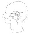
기 발명된 등록발명 제100769289호에는 전기적 신호를 물리적 진동으로 변환 시키는 진동소자(10)를 귓바퀴의 뒷면에 밀착시켜 해당 진동을 귓바퀴의 귓바퀴 연골에 전달 시키며 해당 진동소자(10)가 귓바퀴에서 떨어져 내리지 않게 귓바퀴의 안쪽 면에 위치하는 대응소자와 귓바퀴의 뒤쪽면에 위치한 진동소자를 고정 시키는 고정 수단을 포함 하여 구성 하여 귓바퀴를 진동시키는 진동스피커 및 이를 구비한 이어셋을 제공 하였는데,[0076] Invented Patent No. 100769289 discloses a vibrating
이와 같이 기 발명된 등록발명 제100769289호에는 이어셋을 착용시 귓바퀴를 집게등으로 집어야 하므로 오랫 동안 착용시 귓바퀴에 통증을 줄 수 있고, 귓바퀴의 뒤에 진동소자(10)가 위치하므로 머리뼈를 진동시켜 고막을 거치지 않고 바로 청각 신경을 자극 하는데 효과가 적을 수 있는 문제점을 내재하고 있는 것이다.As described above, the invention disclosed in the invention 100769289 has to wear the ear wheels with a forceps when wearing the earset, can cause pain in the ear wheels when worn for a long time, vibrating the head bone because the
본 발명이 해결하고자 하는 과제는 골전도헤드셋의 골전도스피커를 귀 옆의 머리뼈에 밀착을 시켜서 음악소리나 통신 소리를 고막을 거치지 않고 진동으로 듣고자 하는 것으로서, 골전도스피커를 귀 옆의 머리뼈에 밀착시키기 위해서는 골전도헤드셋처럼 귀 바퀴 위에 헤드 밴드를 걸치게 구성하고 헤드 밴드의 텐션을 이용하여 골전도스피커를 머리뼈에 밀착하거나 집게로 귓바퀴를 집어서 잡아야 하는데, The problem to be solved by the present invention is to make the bone conduction speaker of the bone conduction headset close to the head bone next to the ear to listen to the sound of music or communication without going through the eardrum as a vibration, the bone conduction speaker head next to the ear In order to be in close contact with the bone, the headband should be worn over the ear wheels like the bone conduction headset, and the bone conduction speaker should be closely attached to the head bone using the tension of the headband, or the pinnap wheel should be grasped by the forceps.
이는 골전도헤드셋의 구성체가 크게 되거나, 귓바퀴에 설치하므로 귓바퀴의 통증이나 골전도스피커의 진동 특성이 제대로 청각 신경에 전달이 되지 않는 문제점을 내포 하고 있어서,This is because the structure of the bone conduction headset is enlarged or installed in the auricles, so that the pain of the auricles and the vibration characteristics of the bone conduction speaker are not properly transmitted to the auditory nerve,
본 발명에서는 간단하게 설치가 되고 골전도스피커의 진동특성을 유지 하며 다른 소리도 동시에 들을 수 있는 골전도 이어폰을 제공하고자 하는데 그 주된 목적이 있는 것이다.In the present invention, the main purpose is to provide a bone conduction earphone that is simply installed and maintains the vibration characteristics of the bone conduction speaker and can hear other sounds at the same time.
본 발명은 상기 문제점을 감안해서 이루어진 것으로 간단하게 골전도스피커를 착용하여 골전도헤드셋의 골전도스피커를 귀 옆의 머리뼈에 밀착을 시켜서 음악소리나 통신 소리를 고막을 거치지 않고 난청 예방을 하면서 진동으로 듣고자 하는 것으로서, 본체(300)의 상측에 귀 구멍과 연결되는 이어가이드(250)를 구성하고 이어가이드(250)의 끝단에 이어봉(220)을 구성하여 이어봉(220)이 귀 구멍에 삽입이 되어 착용이 되게 하는데 이어봉(220)의 중앙과 이어가이드(250)의 중앙에는 이어홀(270)을 만들어 이어봉(220)이 귀에 삽입되어 귀를 막아도 주변의 소리가 이어홀(270)을 통해 고막과 청각 신경을 통해 들릴 수 있게 하며, 본체(300)의 옆으로 본체(300)와 약간 이격 하여 골전도스피커를 구성하여 음악 소리나 통신 소리는 음파가 아닌 진동으로 귀 옆의 머리뼈를 통해 고막을 거치지 않고 청각 신경을 통해 들을수 있게 하여 착용은 간단히 귀 구멍에 이어봉(220)으로 삽입 착용하고 골전도스피커(200)로 들을 수 있는 골전도이어폰을 구성한 것으로서,The present invention was made in view of the above problems by simply wearing a bone conduction speaker to make the bone conduction speaker of the bone conduction headset close to the head bone next to the ear to prevent the hearing loss of music or communication sound without going through the eardrum As to listen to, as the upper side of the
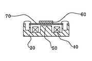
골전도이어폰에 사용되는 골전도유닛(150)은 진동 특성이 좋아야 하는데, 상기의 진동 특성이 좋은 골전도유닛(150)의 구조를 가지기 위해서는 단순히 일반 스피커의 원리를 그대로 이용하여서는 안 되고, 음성 코일(40)이 전자력을 충분히 발생할 수 있게 하고 음성코일(40)과 영구 자석(90)에 형성된 철편(60)과의 전자력이 크게 될 수 있는 구조의 골전도유닛150)을 사용해야 하고, 골전도이어폰의 외부 진동판(100)의 내부에 골전도유닛(150)의 철편(60)을 부착 하고 철편(60)은 내부 진동판(70)에 부착 하고, 내부 진동판(70)은 요크(20)에 나사로 고정을 하며, 음성코일(40)을 요크(20)에 에폭시등으로 고정을 하고 영구 자석(90)은 철편(60)과 외부 진동판(100) 사이에 설치를 하여 자력을 발생시켜 음성코일(40)이 발생시키는 요크(20)의 중앙자극(50)과의 사이에서는 흡인력과 반발력으로 강한 진동을 일으키게 되며, 외부의 MP3 플레이어 등에서 공급되는 음악 파동에 따라 골전도스피커(200)의 외부 진동판(100)이 진동하게 되어 직접적으로 머리뼈를 진동시켜 음악을 듣게 되는 것이다.The
이와 같이 본 발명은 파동 특성이 좋은 골전도유닛(150)을 사용하고, 이어봉(220)을 귀 구멍에 삽입하여 간편하게 착용하고, 이어가이드(250)와 이어봉(220)의 이어홀(270)을 통해 다른 주변 소리를 음파로 동시에 들을 수 있는 골전도이어폰을 구성한 것이 그 특징이다.As described above, the present invention uses the
본 발명은 난청 방지 효과가 있는 골전도스피커(200)를 귀 구멍에 내삽하는 이어봉(220)과 이어가이드(250)를 이용 하여 간단히 착용할 수 있게 한 발명으로서, 자신이 좋아하는 음악을 즐겁게 들으면서도 난청 걱정을 하지 않아도 되고, 골전도헤드셋처럼 복잡하거나 크지 않으며 길을 걸으면서 음악을 들어도 주변의 자동차 소리나 오토바이등의 소리도 들을 수 있어서 충분히 위험요소를 제거할 수 있고, 간단히 착용이 가능하므로 기존의 큰 음악 소리에 의한 난청 문제나 주변 소리도 차단하는 헤드폰의 위험성 등으로부터 해방되어 자유롭고 안전하게 음악소리를 들을수 있게 되어 생활 속에서 음악을 즐기는데 매우 효과적인 매우 유용한 발명이다.The present invention is an invention that can be easily worn by using the
도 1 은 본 발명의 실시예의 정면도를 도시한 것이고, 도 2는 본 발명의 실 시예의 횡단면도를 도시한 것이고, 도 3 은 본 발명의 정면도를 도시한 것이고, 도 4는 본 발명의 횡단면도를 도시한 것이고, 도 5는 본 발명의 골전도유닛 구조의 분리 사시도를 도시한 것이다.1 shows a front view of an embodiment of the invention, FIG. 2 shows a cross sectional view of an embodiment of the invention, FIG. 3 shows a front view of the invention, and FIG. 4 shows a cross sectional view of the invention. 5 is an exploded perspective view of the bone conduction unit structure of the present invention.
도 3에서 보는 바와 같이 본 발명의 골전도이어폰은 골전도스피커(150)와 본체(300)와 이어가이드(250), 이어봉(220), 이어홀(270) 및 골전도스피커 지지대(350)를 포함하여 이루어진다. As shown in FIG. 3, the bone conduction earphone of the present invention includes a
본 발명은 골전도헤드셋의 골전도스피커를 귀 옆의 머리뼈에 밀착을 시켜서 음악소리나 통신 소리를 고막을 거치지 않고 진동으로 듣고자 하는 것으로서, 본체의 상측에 귀 구멍과 연결되는 이어가이드(250)를 구성하고 이어가이드(250)의 끝단에 이어봉(220)을 구성하여 이어봉(220)을 귀 구멍에 삽입 하여 착용이 되게 하는데 이어봉(220)과 이어가이드(250)의 중앙에는 이어홀(270)을 만들어 이어봉(220)이 귀에 삽입되어 귀를 막아도 주변의 소리가 이어홀(270)을 통해서 고막과 청각 신경을 통해 들릴 수 있게 하며, 본체의 옆으로 본체와 약간 이격 하여 골전도스피커(200)를 구성하여 음악 소리나 통신 소리는 음파가 아닌 진동으로 귀 옆의 머리뼈를 통해 고막을 거치지 않고 청각 신경을 통해 직접 들을 수 있게 하고 착용은 간단히 귀 구멍에 이어봉(220)을 삽입 착용하고 골전도스피커(200)로 들을 수 있는 골전도이어폰을 구성 한 것으로서,The present invention is to contact the bone conduction speaker of the bone conduction headset to the head bone next to the ear to hear the music sound or communication sound through the eardrum without going through the eardrum, the ear guide connected to the ear hole on the upper side of the main body (250) ) And the
골전도이어폰에 사용되는 골전도유닛(150)은 진동 특성이 좋아야 하는데, 상기의 진동 특성이 좋은 골전도유닛(150)의 구조를 가지기 위해서는 단순히 일반 스피커의 원리를 그대로 이용하여서는 안되고, 음성 코일(40)이 전자력을 충분히 발생할수 있게 하고 음성코일(40)과 영구 자석(90)에 형성된 철편(60)과의 전자력이 크게 될 수 있는 구조의 골전도유닛(150)을 사용해야 하고, 골전도이어폰의 외부 진동판(100)의 내부에 골전도스피커(150)의 철편(60)을 부착 하고 철편(60)은 내부 진동판(70)에 부착 하고, 내부 진동판(70)은 요크(20)에 나사로 고정을 하며, 음성코일(40)을 요크(20)에 에폭시등으로 고정을 하고 영구 자석(90)은 철편(60)과 외부 진동판(100) 사이에 설치를 하여 자력을 발생시켜 음성코일(40)이 발생시키는 요크(20)의 중앙자극(50)과의 사이에서 흡인력과 반발력으로 강한 진동을 일으키게 되며, 외부의 MP3 플레이어 등에서 공급되는 음악 파동에 따라 골전도이어폰의 외부 진동판(100)이 진동하게 되어 직접적으로 머리뼈를 진동시켜 음악을 듣게 되는 것이다.The
이와 같이 본 발명은 파동 특성이 좋은 골전도유닛(150)을 사용하고, 이어가이드(250)와 이어봉(220)으로 귀 구멍에 삽입하여 간편하게 착용하고, 이어가이드(250)와 이어봉(220)의 이어홀(270)을 통해 다른 주변 소리를 음파로 동시에 들을 수 있는 골전도이어폰을 구성한 것이 그 특징이다.As described above, the present invention uses the
도 1은 본 발명의 실시예의 정면도.1 is a front view of an embodiment of the present invention.
도 2는 본 발명의 실시예의 횡단면도.2 is a cross-sectional view of an embodiment of the present invention.
도 3은 본 발명의 정면도.3 is a front view of the present invention.
도 4는 본 발명의 횡단면도.4 is a cross-sectional view of the present invention.
도 5은 본 발명의 골전도유닛의 분리사시도.5 is an exploded perspective view of the bone conduction unit of the present invention.
도 6는 본 발명의 다른 실시예의 골전도유닛의 분리사시도.Figure 6 is an exploded perspective view of the bone conduction unit of another embodiment of the present invention.
도 7는 본 발명의 골전도유닛의 종 단면도.Figure 7 is a longitudinal cross-sectional view of the bone conduction unit of the present invention.
도 8은 본 발명의 다른 실시예의 골전도유닛의 종 단면도.8 is a longitudinal cross-sectional view of a bone conduction unit of another embodiment of the present invention.
도 9은 본 발명의 다른 실시예의 골전도유닛의 종 단면도.9 is a longitudinal cross-sectional view of a bone conduction unit of another embodiment of the present invention.
도 10은 도 9의 골전도유닛의 횡 단면도.10 is a cross-sectional view of the bone conduction unit of FIG.
도 11는 본 발명의 다른 실시예의 골전도유닛의 종 단면도.Figure 11 is a longitudinal cross-sectional view of a bone conduction unit of another embodiment of the present invention.
도 12은 본 발명의 다른 실시예의 골전도유닛의 종 단면도.12 is a longitudinal cross-sectional view of a bone conduction unit of another embodiment of the present invention.
도 13는 종래의 실시 상태의 정면도.13 is a front view of a conventional embodiment.
도 14은 종래의 다른 실시 상태의 정면도.14 is a front view of another conventional embodiment.
< 도면의 주요부분에 대한 부호의 설명 >Description of the Related Art
10 : 케이스10: case
20 : 요크20: York
30 30' : 연장면30 30 ': Extension surface
40 : 음성코일40: voice coil
50 : 중앙자극50: central stimulation
60 : 철편60: iron piece
70 : 내부 진동판70: internal diaphragm
80 : 고정나사80: set screw
90 : 영구자석90: permanent magnet
100 : 외부 진동판100: external diaphragm
150 : 골전도유닛150: bone conduction unit
200 : 골전도스피커200: bone conduction speaker
220 : 이어봉220: ear bar
250 : 이어가이드250: ear guide
270 : 이어홀270 ear hole
300 : 본체300 body
Claims (8)
Translated fromKoreanPriority Applications (1)
| Application Number | Priority Date | Filing Date | Title |
|---|---|---|---|
| KR1020090067540AKR20110010033A (en) | 2009-07-23 | 2009-07-23 | Bone conduction earphone |
Applications Claiming Priority (1)
| Application Number | Priority Date | Filing Date | Title |
|---|---|---|---|
| KR1020090067540AKR20110010033A (en) | 2009-07-23 | 2009-07-23 | Bone conduction earphone |
Publications (1)
| Publication Number | Publication Date |
|---|---|
| KR20110010033Atrue KR20110010033A (en) | 2011-01-31 |
Family
ID=43615563
Family Applications (1)
| Application Number | Title | Priority Date | Filing Date |
|---|---|---|---|
| KR1020090067540AWithdrawnKR20110010033A (en) | 2009-07-23 | 2009-07-23 | Bone conduction earphone |
Country Status (1)
| Country | Link |
|---|---|
| KR (1) | KR20110010033A (en) |
Cited By (6)
| Publication number | Priority date | Publication date | Assignee | Title |
|---|---|---|---|---|
| CN107809695A (en)* | 2017-11-29 | 2018-03-16 | 苏州佑克骨传导科技有限公司 | A kind of back-wear type bone conduction earphone |
| KR20190010637A (en)* | 2016-05-24 | 2019-01-30 | 이노바 디자인 솔루션즈 리미티드 | Portable physiology monitor configured to measure eardrum temperature |
| KR102003951B1 (en) | 2018-11-27 | 2019-07-25 | 박태수 | Earphone |
| KR20200063025A (en) | 2019-04-22 | 2020-06-04 | 박태수 | Earphone |
| KR20230172802A (en) | 2022-06-16 | 2023-12-26 | 주식회사 도아드림 | Bone conduction earphones with automatic volume control |
| WO2025166496A1 (en)* | 2024-02-05 | 2025-08-14 | 深圳市韶音科技有限公司 | Earphone |
- 2009
- 2009-07-23KRKR1020090067540Apatent/KR20110010033A/ennot_activeWithdrawn
Cited By (6)
| Publication number | Priority date | Publication date | Assignee | Title |
|---|---|---|---|---|
| KR20190010637A (en)* | 2016-05-24 | 2019-01-30 | 이노바 디자인 솔루션즈 리미티드 | Portable physiology monitor configured to measure eardrum temperature |
| CN107809695A (en)* | 2017-11-29 | 2018-03-16 | 苏州佑克骨传导科技有限公司 | A kind of back-wear type bone conduction earphone |
| KR102003951B1 (en) | 2018-11-27 | 2019-07-25 | 박태수 | Earphone |
| KR20200063025A (en) | 2019-04-22 | 2020-06-04 | 박태수 | Earphone |
| KR20230172802A (en) | 2022-06-16 | 2023-12-26 | 주식회사 도아드림 | Bone conduction earphones with automatic volume control |
| WO2025166496A1 (en)* | 2024-02-05 | 2025-08-14 | 深圳市韶音科技有限公司 | Earphone |
Similar Documents
| Publication | Publication Date | Title |
|---|---|---|
| JP6652164B2 (en) | Sound output device | |
| KR101176827B1 (en) | Audio apparatus | |
| US10034076B2 (en) | Earphone | |
| KR100934273B1 (en) | Vibration earphone | |
| KR100922337B1 (en) | Earphones with rubber shocks | |
| JP6515392B2 (en) | Voice vibration generator | |
| CN111670581B (en) | Listening device | |
| JPWO2017168903A1 (en) | Sound playback device | |
| CN101106831A (en) | earphones in ear | |
| CN111955017B (en) | Electroacoustic transducers and acoustic devices | |
| JP2012525721A (en) | Bone conduction headphones | |
| CN111988696B (en) | earphone | |
| JP2009260883A (en) | Earphone for person with hearing loss | |
| JP2004205839A (en) | Hearing aid | |
| JPWO2016067754A1 (en) | Sound output device | |
| KR20110010033A (en) | Bone conduction earphone | |
| CN216357249U (en) | TWS bone acoustic conduction earphone | |
| JP2008270879A (en) | Receiver | |
| CN112423182B (en) | Improved bone conduction earphone | |
| CN212572925U (en) | Earphone set | |
| JP6421360B2 (en) | Inner earphone | |
| CN105282636B (en) | A kind of acoustic vibration loudspeaker and the health care massage earphone using the vibrating loudspeakers | |
| JP7347927B2 (en) | Electroacoustic transducers and audio equipment | |
| KR20120000147A (en) | Soundproof microphone headset | |
| KR20110014759A (en) | Bone conduction earset |
Legal Events
| Date | Code | Title | Description |
|---|---|---|---|
| PA0109 | Patent application | Patent event code:PA01091R01D Comment text:Patent Application Patent event date:20090723 | |
| PG1501 | Laying open of application | ||
| PC1203 | Withdrawal of no request for examination | ||
| WITN | Application deemed withdrawn, e.g. because no request for examination was filed or no examination fee was paid |