KR20110005875A - Monitoring method of flow circuit and monitoring device of flow circuit - Google Patents
Monitoring method of flow circuit and monitoring device of flow circuitDownload PDFInfo
- Publication number
- KR20110005875A KR20110005875AKR1020107025747AKR20107025747AKR20110005875AKR 20110005875 AKR20110005875 AKR 20110005875AKR 1020107025747 AKR1020107025747 AKR 1020107025747AKR 20107025747 AKR20107025747 AKR 20107025747AKR 20110005875 AKR20110005875 AKR 20110005875A
- Authority
- KR
- South Korea
- Prior art keywords
- signal
- flow circuit
- pressure
- integrity
- frequency
- Prior art date
- Legal status (The legal status is an assumption and is not a legal conclusion. Google has not performed a legal analysis and makes no representation as to the accuracy of the status listed.)
- Granted
Links
Images


Classifications
- G—PHYSICS
- G01—MEASURING; TESTING
- G01M—TESTING STATIC OR DYNAMIC BALANCE OF MACHINES OR STRUCTURES; TESTING OF STRUCTURES OR APPARATUS, NOT OTHERWISE PROVIDED FOR
- G01M3/00—Investigating fluid-tightness of structures
- G01M3/02—Investigating fluid-tightness of structures by using fluid or vacuum
- G01M3/26—Investigating fluid-tightness of structures by using fluid or vacuum by measuring rate of loss or gain of fluid, e.g. by pressure-responsive devices, by flow detectors
- G01M3/28—Investigating fluid-tightness of structures by using fluid or vacuum by measuring rate of loss or gain of fluid, e.g. by pressure-responsive devices, by flow detectors for pipes, cables or tubes; for pipe joints or seals; for valves ; for welds
- G01M3/2807—Investigating fluid-tightness of structures by using fluid or vacuum by measuring rate of loss or gain of fluid, e.g. by pressure-responsive devices, by flow detectors for pipes, cables or tubes; for pipe joints or seals; for valves ; for welds for pipes
- G01M3/2815—Investigating fluid-tightness of structures by using fluid or vacuum by measuring rate of loss or gain of fluid, e.g. by pressure-responsive devices, by flow detectors for pipes, cables or tubes; for pipe joints or seals; for valves ; for welds for pipes using pressure measurements
- A—HUMAN NECESSITIES
- A61—MEDICAL OR VETERINARY SCIENCE; HYGIENE
- A61M—DEVICES FOR INTRODUCING MEDIA INTO, OR ONTO, THE BODY; DEVICES FOR TRANSDUCING BODY MEDIA OR FOR TAKING MEDIA FROM THE BODY; DEVICES FOR PRODUCING OR ENDING SLEEP OR STUPOR
- A61M1/00—Suction or pumping devices for medical purposes; Devices for carrying-off, for treatment of, or for carrying-over, body-liquids; Drainage systems
- A61M1/14—Dialysis systems; Artificial kidneys; Blood oxygenators ; Reciprocating systems for treatment of body fluids, e.g. single needle systems for hemofiltration or pheresis
- A—HUMAN NECESSITIES
- A61—MEDICAL OR VETERINARY SCIENCE; HYGIENE
- A61M—DEVICES FOR INTRODUCING MEDIA INTO, OR ONTO, THE BODY; DEVICES FOR TRANSDUCING BODY MEDIA OR FOR TAKING MEDIA FROM THE BODY; DEVICES FOR PRODUCING OR ENDING SLEEP OR STUPOR
- A61M1/00—Suction or pumping devices for medical purposes; Devices for carrying-off, for treatment of, or for carrying-over, body-liquids; Drainage systems
- A61M1/36—Other treatment of blood in a by-pass of the natural circulatory system, e.g. temperature adaptation, irradiation ; Extra-corporeal blood circuits
- A61M1/3621—Extra-corporeal blood circuits
- A61M1/3653—Interfaces between patient blood circulation and extra-corporal blood circuit
- A61M1/3656—Monitoring patency or flow at connection sites; Detecting disconnections
- A—HUMAN NECESSITIES
- A61—MEDICAL OR VETERINARY SCIENCE; HYGIENE
- A61M—DEVICES FOR INTRODUCING MEDIA INTO, OR ONTO, THE BODY; DEVICES FOR TRANSDUCING BODY MEDIA OR FOR TAKING MEDIA FROM THE BODY; DEVICES FOR PRODUCING OR ENDING SLEEP OR STUPOR
- A61M1/00—Suction or pumping devices for medical purposes; Devices for carrying-off, for treatment of, or for carrying-over, body-liquids; Drainage systems
- A61M1/36—Other treatment of blood in a by-pass of the natural circulatory system, e.g. temperature adaptation, irradiation ; Extra-corporeal blood circuits
- A61M1/3621—Extra-corporeal blood circuits
- A61M1/3653—Interfaces between patient blood circulation and extra-corporal blood circuit
- A61M1/3659—Cannulae pertaining to extracorporeal circulation
- A61M1/3661—Cannulae pertaining to extracorporeal circulation for haemodialysis
- G—PHYSICS
- G01—MEASURING; TESTING
- G01M—TESTING STATIC OR DYNAMIC BALANCE OF MACHINES OR STRUCTURES; TESTING OF STRUCTURES OR APPARATUS, NOT OTHERWISE PROVIDED FOR
- G01M3/00—Investigating fluid-tightness of structures
- G01M3/02—Investigating fluid-tightness of structures by using fluid or vacuum
- A—HUMAN NECESSITIES
- A61—MEDICAL OR VETERINARY SCIENCE; HYGIENE
- A61M—DEVICES FOR INTRODUCING MEDIA INTO, OR ONTO, THE BODY; DEVICES FOR TRANSDUCING BODY MEDIA OR FOR TAKING MEDIA FROM THE BODY; DEVICES FOR PRODUCING OR ENDING SLEEP OR STUPOR
- A61M1/00—Suction or pumping devices for medical purposes; Devices for carrying-off, for treatment of, or for carrying-over, body-liquids; Drainage systems
- A61M1/36—Other treatment of blood in a by-pass of the natural circulatory system, e.g. temperature adaptation, irradiation ; Extra-corporeal blood circuits
- A61M1/3621—Extra-corporeal blood circuits
- A61M1/3639—Blood pressure control, pressure transducers specially adapted therefor
- A—HUMAN NECESSITIES
- A61—MEDICAL OR VETERINARY SCIENCE; HYGIENE
- A61M—DEVICES FOR INTRODUCING MEDIA INTO, OR ONTO, THE BODY; DEVICES FOR TRANSDUCING BODY MEDIA OR FOR TAKING MEDIA FROM THE BODY; DEVICES FOR PRODUCING OR ENDING SLEEP OR STUPOR
- A61M2205/00—General characteristics of the apparatus
- A61M2205/15—Detection of leaks
- A—HUMAN NECESSITIES
- A61—MEDICAL OR VETERINARY SCIENCE; HYGIENE
- A61M—DEVICES FOR INTRODUCING MEDIA INTO, OR ONTO, THE BODY; DEVICES FOR TRANSDUCING BODY MEDIA OR FOR TAKING MEDIA FROM THE BODY; DEVICES FOR PRODUCING OR ENDING SLEEP OR STUPOR
- A61M2205/00—General characteristics of the apparatus
- A61M2205/18—General characteristics of the apparatus with alarm
- A—HUMAN NECESSITIES
- A61—MEDICAL OR VETERINARY SCIENCE; HYGIENE
- A61M—DEVICES FOR INTRODUCING MEDIA INTO, OR ONTO, THE BODY; DEVICES FOR TRANSDUCING BODY MEDIA OR FOR TAKING MEDIA FROM THE BODY; DEVICES FOR PRODUCING OR ENDING SLEEP OR STUPOR
- A61M2230/00—Measuring parameters of the user
- A61M2230/04—Heartbeat characteristics, e.g. ECG, blood pressure modulation
- A61M2230/06—Heartbeat rate only
- A—HUMAN NECESSITIES
- A61—MEDICAL OR VETERINARY SCIENCE; HYGIENE
- A61M—DEVICES FOR INTRODUCING MEDIA INTO, OR ONTO, THE BODY; DEVICES FOR TRANSDUCING BODY MEDIA OR FOR TAKING MEDIA FROM THE BODY; DEVICES FOR PRODUCING OR ENDING SLEEP OR STUPOR
- A61M5/00—Devices for bringing media into the body in a subcutaneous, intra-vascular or intramuscular way; Accessories therefor, e.g. filling or cleaning devices, arm-rests
- A61M5/14—Infusion devices, e.g. infusing by gravity; Blood infusion; Accessories therefor
- A61M5/168—Means for controlling media flow to the body or for metering media to the body, e.g. drip meters, counters ; Monitoring media flow to the body
- A61M5/16831—Monitoring, detecting, signalling or eliminating infusion flow anomalies
- A61M5/16854—Monitoring, detecting, signalling or eliminating infusion flow anomalies by monitoring line pressure
- A61M5/16859—Evaluation of pressure response, e.g. to an applied pulse
Landscapes
- Health & Medical Sciences (AREA)
- Heart & Thoracic Surgery (AREA)
- Vascular Medicine (AREA)
- Life Sciences & Earth Sciences (AREA)
- General Health & Medical Sciences (AREA)
- Anesthesiology (AREA)
- Biomedical Technology (AREA)
- Hematology (AREA)
- Veterinary Medicine (AREA)
- Animal Behavior & Ethology (AREA)
- Engineering & Computer Science (AREA)
- Public Health (AREA)
- Cardiology (AREA)
- Urology & Nephrology (AREA)
- Physics & Mathematics (AREA)
- General Physics & Mathematics (AREA)
- Emergency Medicine (AREA)
- External Artificial Organs (AREA)
Abstract
Translated fromKoreanDescription
Translated fromKorean본 발명은 일반적으로 유동 회로들의 모니터링에 관한 것으로, 구체적으로 압력 측정에 기반한 유동 회로의 무결성에 대한 모니터링에 관한 것이다. 본 발명은 체외 혈액 유동 회로들을 포함하여, 체외 혈액 처리와 관련하여 사용되는 유동 회로들에 적용가능하다.The present invention relates generally to the monitoring of flow circuits, and more particularly to the monitoring of the integrity of flow circuits based on pressure measurements. The invention is applicable to flow circuits used in connection with extracorporeal blood processing, including extracorporeal blood flow circuits.
체외 혈액 처리에서는, 체외 혈액 유동 회로를 통해, 혈액이 환자의 체외로 취출되고 처리된 다음에 환자의 체내로 재도입된다. 일반적으로는, 하나 이상의 펌프 장치들에 의해 혈액이 상기 체외 혈액 유동 회로를 통해 순환된다. 상기 체외 혈액 유동 회로는, 환자의 혈관 내로 삽입되는 바늘들 또는 카테터들과 같은 하나 이상의 액세스 장치들의 형태를 이루고 있는 것이 전형적인 혈관 액세스를 통해 환자와 연결된다. 그러한 체외 혈관 처리에는 혈액 투석, 혈액 투석 여과, 혈액 여과, 혈장 사혈 등이 포함된다.In extracorporeal blood processing, through an extracorporeal blood flow circuit, blood is drawn out of the patient's body and processed and then reintroduced into the patient's body. Generally, blood is circulated through the extracorporeal blood flow circuit by one or more pump devices. The extracorporeal blood flow circuit is connected to the patient via vascular access, typically in the form of one or more access devices such as needles or catheters inserted into the patient's blood vessels. Such extracorporeal vascular treatments include hemodialysis, hemodialysis filtration, blood filtration, blood plasma, and the like.
체외 혈액 치료에서는, 체외 혈액 유동 회로의 오작동에 대한 위험성을 최소화하는 것이 절대적으로 필요한데, 그 이유는 이러한 것들이 잠재적으로 환자의 생명을 위협하는 상황을 초래할 수 있기 때문이다. 예컨대 혈액 추출을 위한 액세스 장치(예컨대 동맥 바늘/카테터)가 혈관으로부터 느슨해짐으로 인해 공기가 상기 체외 혈액 유동 회로 내로 흡입되게 함으로써, 또는 혈액 재도입을 위한 액세스 장치(예컨대, 정맥 바늘/카테터)가 느슨해짐으로 인해 수분 내로 환자 체내에서 혈액이 유출되게 함으로써, 혈관 액세스가 중단되는 경우에는 심각한 상황이 생길 수 있다. 다른 오작동들은, 예컨대 액세스 장치가 혈관의 벽들에 과도하게 근접 배치됨으로써, 또는 체외 혈액 유동 회로 내의 튜브가 엉키거나 꼬임으로써, 혈관 액세스가 방해를 받게 되거나 차단되어 버리는 것에 기인한 것일 수 있다.In extracorporeal blood therapy, it is absolutely necessary to minimize the risk of malfunction of the extracorporeal blood flow circuit, as these can potentially lead to a life-threatening situation. For example, by allowing air to be sucked into the extracorporeal blood flow circuit due to the loosening of an access device (such as an arterial needle / catheter) from blood vessels, or an access device (such as a venous needle / catheter) for The looseness causes blood to leak out of the patient's body in minutes, which can lead to serious situations when vascular access is interrupted. Other malfunctions may be due to, for example, the access device being placed too close to the walls of the blood vessel, or due to entanglement or twisting of the tubes in the extracorporeal blood flow circuit, which impedes or blocks access to the vessel.
이를 위해, 체외 혈액 처리를 위한 장치는, 혈액 유동 회로의 무결성을 모니터링하며 잠재적으로 위험한 상황이 검출될 때마다 알람을 발생시키고/발생시키거나 적합한 조치가 취해지게 하는 하나 이상의 감시 장치들을 포함할 수 있다. 그러한 감시 장치들은 상기 혈액 유동 회로에서 하나 이상의 압력 센서들로부터의 측정 신호들을 통해 작동할 수 있다. 통상적으로, 상기 모니터링은 하나 이상의 문턱값들과 하나 이상의 측정된 압력 레벨들을 비교함으로써 수행된다. 예를 들면, 혈액 추출의 실패는, 상기 혈액 유동 회로 내에 공기가 도입됨으로써, 측정된 압력이 대기압에 접근할 수 있거나, 또는 혈액 유동이 방해를 받거나 차단되어 버림으로써 측정된 압력이 낮은 레벨로 떨어질 수 있다는 것을 포함할 수 있다. 혈액의 재도입 실패는 측정되는 압력의 저하로서 탐지 가능할 수 있다. 그러나, 적합한 문턱값들을 설정하는 것이 어려울 수 있는데, 그 이유는 상기 혈액 유동 회로 내의 압력이 처리에 따라 다를 수 있고, 또한 예컨대 환자가 움직인 결과로서 치료 중일 때마다 다를 수 있기 때문이다.To this end, the device for extracorporeal blood processing may include one or more monitoring devices that monitor the integrity of the blood flow circuit and trigger an alarm and / or take appropriate action whenever a potentially hazardous situation is detected. have. Such monitoring devices can operate via measurement signals from one or more pressure sensors in the blood flow circuit. Typically, the monitoring is performed by comparing one or more thresholds with one or more measured pressure levels. For example, a failure of blood extraction may be caused by the introduction of air into the blood flow circuit such that the measured pressure may approach atmospheric pressure, or the measured pressure may drop to a low level as the blood flow is obstructed or blocked. May include. Failure to reintroduce blood may be detectable as a drop in measured pressure. However, setting suitable thresholds can be difficult because the pressure in the blood flow circuit can vary depending on the treatment and can also vary each time, for example, during treatment as a result of the patient's movement.
모니터링의 정확도를 높이기 위해, WO 97/10013에서는, 몇 가지 옵션들 중 하나로서, 측정 압력에서 심장 신호(heart signal)를 검출하고 상기 심장 신호를 상기 혈액 유동 회로의 무결성에 대한 표시자, 특히 혈관 액세스의 무결성에 대한 표시자로서 사용하는 것이 제안되어 있다. 상기 심장 신호는, 환자의 심장에 의해 생성되고 혈관 액세스를 통해 환자의 순환계로부터 체외 혈액 유동 회로로 전달되는 압력파를 나타낸다. 상기 혈관 액세스의 오작동들은 심장에서 생성된 압력파를 상기 혈액 유동 회로로 전송하는 것을 방해함으로써, 상기 심장 신호가 바뀌거나 또는 심지어는 소멸하도록 한다. 상기 측정 압력은 또한 상기 체외 혈액 유동 회로 내의 혈액 펌프에 의해 생성된 강한 압력파를 포함한다. WO 97/10013에서는, 상기 모니터링이 혈액 펌프로부터 비롯된 주파수 성분들을 제거하도록 측정된 압력 신호를 필터링한 다음에, 필터링된 압력 신호를 분석함으로써 상기 심장 신호를 검출하는 것을 포함한다. 그러나, 상기 심장 신호가 매우 약하고/약하거나 상기 심장 박동 주파수가 상기 혈액 펌프의 주파수 성분들 중 어느 하나에 근접해 있는 경우, 상기 심장 신호는 검출이 불가능해질 수 있고 잘못된 알람 신호가 발생하게 된다. 그러한 경우는, 환자의 심장 박동 주파수, 그리고 또한 가끔은 상기 혈액 펌프의 주파수가 치료 도중에 변하게 되기 때문에 생기는 것으로 보이지 않는다.In order to increase the accuracy of the monitoring, WO 97/10013, in one of several options, detects a heart signal at a measuring pressure and displays the heart signal as an indicator for the integrity of the blood flow circuit, in particular blood vessels. It is proposed to use it as an indicator of the integrity of the access. The cardiac signal represents a pressure wave generated by the patient's heart and transmitted from the patient's circulatory system to the extracorporeal blood flow circuit through vascular access. Malfunctions of the vascular access interfere with the transmission of pressure waves generated in the heart to the blood flow circuit, thereby causing the heart signal to change or even disappear. The measured pressure also includes a strong pressure wave generated by a blood pump in the extracorporeal blood flow circuit. In WO 97/10013, the monitoring comprises filtering the measured pressure signal to remove frequency components originating from the blood pump, and then detecting the cardiac signal by analyzing the filtered pressure signal. However, if the heart signal is very weak and / or the heart beat frequency is close to any one of the frequency components of the blood pump, the heart signal may become undetectable and a false alarm signal is generated. Such cases do not appear to occur because the patient's heartbeat frequency, and also sometimes the frequency of the blood pump, changes during treatment.
유동 회로의 무결성을 모니터링하고자 하는 해당 요구들이 다른 기술분야들에서 생길 수 있다.Corresponding needs to monitor the integrity of flow circuits can arise in other technical fields.
본 발명의 목적은 위에서 언급된 선행기술의 제약들 중 하나 이상을 적어도 부분적으로 극복하는 것이다. 특히, 본 발명은, 바람직하게는 유동 회로의 오작동을 검출하는 확실성을 높여주면서, 압력 측정을 이용하여 유동 회로의 무결성을 모니터링하기 위한 대체적이거나 보완적인 기법을 제공하는 데 그 목적이 있다.It is an object of the present invention to at least partially overcome one or more of the above mentioned limitations of the prior art. In particular, it is an object of the present invention to provide an alternative or complementary technique for monitoring the integrity of a flow circuit using pressure measurements, preferably increasing the certainty of detecting the malfunction of the flow circuit.
이러한 목적 및 이하의 설명으로부터 나타나게 되는 다른 목적들은 독립 청구항들에 따른 방법들, 장치들, 컴퓨터 프로그램 제품, 및 기기들을 통해 적어도 부분적으로 달성되며, 이들의 실시예는 종속 청구항에 의해 한정된다.These and other objects that emerge from the following description are at least partly achieved through methods, apparatuses, computer program products, and apparatuses according to the independent claims, the embodiments of which are defined by the dependent claims.
본 발명은, 펌프 장치를 포함하며 수용기와 유체 연통되어 있는 유동 회로의 무결성을 모니터링하는 기법에 관한 것이다. 본 발명의 다른 태양들에서, 본 발명의 한 가지 진보성 개념은 압력 신호 내의 박동 신호의 존재 및 부재를 사용하여 상기 유동 회로의 무결성을 평가하는 것을 포함한다. 상기 박동 신호는 상기 압력 신호의 진폭 변조로서 그 자체를 명확히 나타내며 상기 유동 회로에서 펌프 장치에 의해 생성된 압력파들과 상기 수용기와 결합된 펄스 생성기에 의해 발생되는 압력파들 간의 간섭에 의해 형성된다. 상기 압력 신호에서 상기 펄스 생성기에 의해 생성된 신호 성분을 분리시키려고 하는 대신에, 그러한 신호 성분의 존재가 결과적으로는 박동의 부수적인 효과로서 식별된다. 일반적으로, 박동은, 근접한 간격으로 이격된 주파수들을 갖는 2개의 신호들이 함께 추가될 때 특히 주목할 만한 현상이다. 따라서, 선행기술의 기법이 작동하지 않을 경우에, 즉 환자의 심장 주파수가 펌프 장치의 주파수 성분에 근접해 있는 경우에 사용되도록 하기에 박동 신호 검출은 본질적으로 매우 적합한 것이다.The present invention relates to a technique for monitoring the integrity of a flow circuit comprising a pump device and in fluid communication with a receiver. In other aspects of the present invention, one inventive concept includes evaluating the integrity of the flow circuit using the presence and absence of a pulsating signal in the pressure signal. The pulsating signal manifests itself as an amplitude modulation of the pressure signal and is formed by interference between pressure waves generated by a pump device in the flow circuit and pressure waves generated by a pulse generator coupled to the receiver. Instead of trying to separate the signal components produced by the pulse generator from the pressure signal, the presence of such signal components is consequently identified as a side effect of the pulsation. In general, pulsation is a particularly notable phenomenon when two signals with frequencies spaced at close intervals are added together. Thus, pulsatile signal detection is inherently well suited for use when prior art techniques do not work, i.e. when the patient's heart frequency is close to the frequency component of the pump device.
본 개시내용과 관련하여, 박동 신호의 "부재(absence)"는, 상기 박동 신호가 보이지 않게 되는 것이거나, 또는 상기 박동 신호가 "존재"하고 있는 것으로 간주되는 박동 신호와 비교해 볼 때 크기 면에서 상당히 감소해 있는 것을 의미할 수 있다. 존재 또는 부재의 판단은, 압력 신호에 기초하여 평가 매개변수를 계산하고 상기 평가 매개변수를 문턱값과 비교하는 것을 포함할 수 있다.In the context of the present disclosure, the “absence” of the pulsating signal is in terms of magnitude compared to the pulsating signal in which the pulsating signal is made invisible or the pulsating signal is considered to be “existing”. This may mean a significant decrease. The determination of presence or absence may include calculating an evaluation parameter based on the pressure signal and comparing the evaluation parameter with a threshold.
위에서 언급된 발명의 개념이 체외 혈액 처리 분야 외에서도 사용될 수 있다는 것을 이해해야 한다. 기본적으로, 이는, 펌프 장치가 임의의 타입의 수용기(즉, 환자뿐만이 아니라 임의의 타입의 수용기)로 및/또는 상기 임의의 타입의 수용기로부터 유체를 전달하는 임의의 타입의 유동 회로의 무결성을 모니터링하기 위해 사용될 수 있다. 임의의 타입의 펄스 생성기는 상기 수용기 내에 압력파들을 생성시킬 수 있으며, 임의의 타입의 압력 센서는 상기 유동 회로 내의 압력을 측정하기 위해 사용될 수 있다. 상기 펄스 생성기로부터의 압력파들이 검출될 수 있거나 상기 유동 회로에서 측정된 압력이 상당한 크기를 갖는 한, 상기 유동 회로의 무결성은 온전한 것으로 간주될 수 있다.It should be understood that the inventive concepts mentioned above may be used outside the field of extracorporeal blood processing. Basically, this monitors the integrity of any type of flow circuit that the pump device delivers fluid to and from any type of receptor (ie, any type of receptor as well as a patient). Can be used to Any type of pulse generator can generate pressure waves in the receiver, and any type of pressure sensor can be used to measure the pressure in the flow circuit. As long as pressure waves from the pulse generator can be detected or the pressure measured in the flow circuit has a significant magnitude, the integrity of the flow circuit can be considered intact.
본 발명의 제1 태양은 수용기와 유체 연통되어 있는 유동 회로의 무결성을 모니터링하는 방법으로서, 상기 유동 회로가 상기 유동 회로를 통해 유체를 전달하기 위한 펌프 장치를 포함하며, 상기 유동 회로의 무결성에 대한 모니터링 방법은, 압력 센서로부터의 압력 신호를 수신하는 단계로서, 상기 압력 신호가 상기 수용기 또는 상기 유동 회로 내의 유체 압력을 나타내는 것인 단계; 상기 수용기와 결합된 펄스 생성기에 의해 발생된 압력파들과 상기 펌프 장치에 의해 발생된 압력파들 간의 간섭에 의해 형성되는 박동 신호를 검출하기 위해 상기 압력 신호를 처리하는 단계; 및 상기 박동 신호의 존재 또는 부재에 적어도 부분적으로 기반하여 상기 유동 회로의 무결성을 판단하는 단계를 포함한다.A first aspect of the invention is a method of monitoring the integrity of a flow circuit in fluid communication with a receiver, the flow circuit comprising a pump device for delivering fluid through the flow circuit, wherein The monitoring method comprises the steps of receiving a pressure signal from a pressure sensor, the pressure signal representing a fluid pressure in the receiver or the flow circuit; Processing the pressure signal to detect a pulsating signal formed by interference between pressure waves generated by a pulse generator coupled to the receiver and pressure waves generated by the pump device; And determining the integrity of the flow circuit based at least in part on the presence or absence of the pulsating signal.
일 실시예에서, 상기 박동 신호는 시간 영역에서 상기 압력 신호를 분석함으로써 검출된다.In one embodiment, the pulsating signal is detected by analyzing the pressure signal in the time domain.
일 실시예에서, 상기 유동 회로의 무결성에 대한 모니터링 방법은, 상기 펌프 장치의 펌프 주파수에 관련된 하나 이상의 특정 주파수들을 획득하는 단계; 및 상기 특정 주파수들 중 하나의 특정 주파수만 제외한 모든 특정 주파수들이 제거된 적어도 하나의 필터링된 압력 신호를 생성하는 단계를 더 포함한다. 이때, 상기 필터링된 압력 신호는 상기 박동 신호의 검출을 위해 처리될 수 있다. 상기 적어도 하나의 특정 주파수는 절반의 펌프 주파수, 펌프 주파수, 및 이들의 조파 주파수들 중 하나 이상의 주파수들을 포함할 수 있다.In one embodiment, the method for monitoring the integrity of the flow circuit comprises: obtaining one or more specific frequencies related to the pump frequency of the pump device; And generating at least one filtered pressure signal from which all specific frequencies except only one of the specific frequencies have been removed. In this case, the filtered pressure signal may be processed to detect the pulsating signal. The at least one specific frequency may comprise one or more of half pump frequency, pump frequency, and their harmonic frequencies.
일 실시예에서, 상기 처리는 상기 필터링된 압력 신호의 포락선(envelope)을 결정하는 것을 포함한다. 상기 포락선의 결정은, 상기 필터링된 신호로부터 시간 순차적 첨두값의 어레이를 추출하는 것을 포함할 수 있다. 상기 처리는 상기 포락선에 기반하여 분산 및 미분계수들의 합 중 적어도 하나를 계산하는 것을 더 포함할 수 있다.In one embodiment, the processing includes determining an envelope of the filtered pressure signal. The determination of the envelope may include extracting an array of time sequential peak values from the filtered signal. The processing may further comprise calculating at least one of a sum of variance and differential coefficients based on the envelope.
일 실시예에서, 상기 유동 회로의 무결성에 대한 모니터링 방법은, 상기 박동 신호를 검출하기 위해 상기 필터링된 압력 신호 중 적어도 일부를 하나 이상의 소정 신호 패턴들에 매칭시키는 단계를 더 포함한다.In one embodiment, the method for monitoring the integrity of the flow circuit further comprises matching at least a portion of the filtered pressure signal to one or more predetermined signal patterns to detect the pulsating signal.
일 실시예에서, 상기 적어도 하나의 특정 주파수는, 상기 하나 이상의 특정 주파수를 식별하기 위해 상기 압력 신호를 주파수 영역에서 분석하는 것; 상기 펌프 장치로부터 주파수 측정 신호를 획득하는 것; 및 상기 펌프 장치의 펌프 주파수를 제어하도록 되어 있는 제어기의 설정값을 획득하는 것 중 적어도 하나에 의해 획득된다.In one embodiment, the at least one specific frequency comprises: analyzing the pressure signal in a frequency domain to identify the one or more specific frequencies; Acquiring a frequency measurement signal from the pump device; And obtaining a set point of the controller adapted to control the pump frequency of the pump device.
일 실시예에서, 상기 유동 회로의 무결성에 대한 모니터링 방법은, 상기 펄스 생성기에 의해 발생된 신호 성분의 검출을 위해 상기 압력 신호를 처리하는 단계를 더 포함하고, 상기 유동 회로의 무결성은 또한 상기 신호 성분의 존재 또는 부재에 기반하여 판단된다.In one embodiment, the method for monitoring the integrity of the flow circuit further comprises processing the pressure signal for detection of signal components generated by the pulse generator, wherein the integrity of the flow circuit further includes the signal. Judgment is based on the presence or absence of components.
일 실시예에서, 박동 신호의 검출을 위한 상기 압력 신호의 처리는 상기 압력 신호 내의 상기 신호 성분의 부재에 따라 좌우된다.In one embodiment, the processing of the pressure signal for the detection of a pulsating signal depends on the absence of the signal component in the pressure signal.
일 실시예에서, 상기 유동 회로의 무결성에 대한 모니터링 방법은, 박동 신호의 부재시, 상기 펌프 장치의 펌프 주파수에서의 소정의 변경을 초래하는 단계를 더 포함한다.In one embodiment, the method for monitoring the integrity of the flow circuit further comprises causing a predetermined change in the pump frequency of the pump device in the absence of a pulsating signal.
일 실시예에서, 상기 유동 회로의 무결성에 대한 모니터링 방법은, 상기 펌프 장치가 일시적으로 불활성화되게 하는 단계; 상기 펄스 생성기의 주파수를 식별하는 단계; 및 모든 관련 주파수 성분들이 상기 펄스 생성기의 주파수로부터 오프셋되게 하는 펌프 주파수로 상기 펌프 장치가 활성화되게 하는 단계를 더 포함한다.In one embodiment, the method for monitoring the integrity of the flow circuit comprises: temporarily disabling the pump arrangement; Identifying a frequency of the pulse generator; And causing the pump device to be activated at a pump frequency such that all relevant frequency components are offset from the frequency of the pulse generator.
일 실시예에서, 상기 처리하는 단계는, 상기 압력 신호의 부분적으로 오버래핑하는 신호 세그먼트들의 시퀀스에 따라 수행되고, 각각의 세그먼트의 길이는 소정 시간 윈도우로 제공된다.In one embodiment, said processing is performed according to a sequence of partially overlapping signal segments of said pressure signal, the length of each segment being provided in a predetermined time window.
본 발명의 제2 태양은 환자의 혈관에 연결되는 체외 혈액 유동 회로의 무결성을 모니터링하는 방법으로서, 상기 체외 혈액 유동 회로는 혈액 펌프 장치를 포함하고, 상기 체외 혈액 유동 회로의 무결성에 대한 모니터링 방법은, 상기 체외 혈액 유동 회로 내의 압력 센서로부터의 압력 신호를 수신하는 단계; 각각 상기 환자의 심장에 의해 발생된 압력파들과 혈액 펌프 장치에 의해 발생된 압력파들 간의 간섭에 의해 형성되는 박동 신호를 검출하기 위해 상기 압력 신호를 처리하는 단계; 및 상기 박동 신호의 존재 또는 부재에 적어도 부분적으로 기반하여 상기 체외 혈액 유동 회로의 무결성을 판단하는 단계를 포함한다.A second aspect of the invention provides a method of monitoring the integrity of an extracorporeal blood flow circuit connected to a blood vessel of a patient, wherein the extracorporeal blood flow circuit comprises a blood pump device, and the method for monitoring the integrity of the extracorporeal blood flow circuit is Receiving a pressure signal from a pressure sensor in the extracorporeal blood flow circuit; Processing the pressure signal to detect a pulsating signal formed by interference between pressure waves generated by the heart of the patient and pressure waves generated by a blood pump device, respectively; And determining the integrity of the extracorporeal blood flow circuit based at least in part on the presence or absence of the pulsating signal.
본 발명의 제3 태양은 수용기와 유체 연통되어 있는 유동 회로의 무결성을 모니터링하는 장치로서, 상기 유동 회로는 상기 유동 회로를 통해 유체를 전달하기 위한 펌프 장치를 포함하고, 상기 유동 회로의 무결성에 대한 모니터링 장치는, 압력 센서로부터의 압력 신호를 위한 입력부로서, 상기 압력 신호는 상기 수용기 또는 상기 유동 회로 내의 유체 압력을 나타내는 것인 입력부; 및 상기 수용기와 결합된 펄스 생성기에 의해 발생된 압력파들과 상기 펌프 장치에 의해 발생된 압력파들 간의 간섭에 의해 형성되는 박동 신호를 검출하기 위해 상기 압력 신호를 처리하도록 구성되는 제1 모듈을 포함하는 신호 처리기를 포함하며, 상기 신호 처리기는 상기 박동 신호의 존재 또는 부재에 적어도 부분적으로 기반하여 상기 유동 회로의 무결성을 판단하도록 구성된다.A third aspect of the invention is an apparatus for monitoring the integrity of a flow circuit in fluid communication with a receiver, the flow circuit comprising a pump device for delivering fluid through the flow circuit, The monitoring device comprises an input for a pressure signal from a pressure sensor, the pressure signal representing a fluid pressure in the receiver or the flow circuit; And a first module configured to process the pressure signal to detect a pulsating signal formed by interference between pressure waves generated by a pulse generator coupled to the receiver and pressure waves generated by the pump device. A signal processor, the signal processor configured to determine the integrity of the flow circuit based at least in part on the presence or absence of the pulsating signal.
일 실시예에서, 상기 제1 모듈은 상기 압력 신호를 시간 영역에서 분석함으로써 상기 박동 신호를 검출하도록 구성되어 있다.In one embodiment, the first module is configured to detect the pulsating signal by analyzing the pressure signal in a time domain.
일 실시예에서, 상기 제1 모듈은, 추가로, 상기 펌프 장치의 펌프 주파수에 관련된 하나 이상의 특정 주파수들을 획득하도록 구성되어 있으며, 상기 특정 주파수들 중 하나의 특정 주파수만을 제외한 모든 특정 주파수들이 제거된 적어도 하나의 필터링된 압력 신호를 생성하도록 구성되어 있다.In one embodiment, the first module is further configured to obtain one or more specific frequencies related to the pump frequency of the pump device, wherein all specific frequencies except one of the specific frequencies are removed. And generate at least one filtered pressure signal.
일 실시예에서, 상기 제1 모듈은, 추가로 상기 필터링된 압력 신호의 포락선을 결정하도록 구성되어 있다.In one embodiment, the first module is further configured to determine an envelope of the filtered pressure signal.
일 실시예에서, 상기 제1 모듈은, 추가로, 상기 필터링된 압력 신호로부터 시간 순차적 첨두값의 어레이를 추출함으로써 상기 포락선을 결정하도록 구성되어 있다.In one embodiment, the first module is further configured to determine the envelope by extracting an array of time sequential peaks from the filtered pressure signal.
일 실시예에서, 상기 제1 모듈은, 추가로, 상기 포락선을 기반으로 분산 및 미분계수들의 합 중 적어도 하나를 계산하도록 구성되어 있다.In one embodiment, the first module is further configured to calculate at least one of a sum of variance and differential coefficients based on the envelope.
일 실시예에서, 상기 제1 모듈은, 추가로, 상기 필터링된 압력 신호 중 적어도 일부를 하나 이상의 소정 신호 패턴들에 매칭시켜 상기 박동 신호를 검출하도록 구성되어 있다.In one embodiment, the first module is further configured to detect the pulsating signal by matching at least a portion of the filtered pressure signal to one or more predetermined signal patterns.
일 실시예에서, 상기 신호 처리기는 상기 압력 신호를 처리하여 상기 펄스 생성기에 의해 생성된 신호 성분을 검출하도록 구성된 제2 모듈을 포함하고, 상기 신호 처리기는 또한 상기 신호 성분의 존재 또는 부재에 기반하여 상기 유동 회로의 무결성을 판단하도록 구성되어 있다.In one embodiment, the signal processor includes a second module configured to process the pressure signal to detect a signal component generated by the pulse generator, wherein the signal processor is further based on the presence or absence of the signal component. And determine the integrity of the flow circuit.
일 실시예에서, 상기 신호 처리기는, 오직 상기 제2 모듈이 상기 압력 신호에서 상기 신호 성분을 검출할 수 없을 때에만 상기 제1 모듈이 작동되도록 상기 제1 모듈 및 상기 제2 모듈을 순차적으로 작동시키도록 구성되어 있다.In one embodiment, the signal processor sequentially operates the first module and the second module such that the first module is activated only when the second module is unable to detect the signal component in the pressure signal. It is configured to.
일 실시예에서, 상기 신호 처리기는, 박동 신호의 부재시, 상기 펌프 장치의 펌프 주파수에서의 소정의 변경을 초래하도록 구성되어 있다.In one embodiment, the signal processor is configured to cause a predetermined change in the pump frequency of the pump device in the absence of a pulsating signal.
일 실시예에서, 상기 신호 처리기는, 상기 펌프 장치가 일시적으로 불활성화되게 하도록 구성되어 있고, 상기 펄스 생성기의 주파수를 식별하도록 구성되어 있으며, 모든 관련 주파수 성분들이 상기 펄스 생성기의 주파수로부터 오프셋되게 하는 펌프 주파수로 상기 펌프 장치가 활성화되게 하도록 구성되어 있다.In one embodiment, the signal processor is configured to cause the pump device to be temporarily deactivated, configured to identify the frequency of the pulse generator, and to cause all relevant frequency components to be offset from the frequency of the pulse generator. The pump device is configured to be activated at a pump frequency.
본 발명의 제4 태양은 수용기와 유체 연통되어 있는 유동 회로의 무결성을 모니터링하는 장치로서, 상기 유동 회로는 상기 유동 회로를 통해 유체를 전달하기 위한 펌프 장치를 포함하며, 상기 유동 회로의 무결성에 대한 모니터링 장치는, 압력 센서로부터의 압력 신호를 수신하는 수신 수단으로서, 상기 압력 신호는 상기 수용기 또는 상기 유동 회로 내의 유체 압력을 나타내는 것인 수신 수단; 각각 상기 수용기와 결합된 펄스 생성기에 의해 발생된 압력파들과 상기 펌프 장치에 의해 발생된 압력파들 간의 간섭에 의해 형성되는 박동 신호를 검출하기 위해 상기 압력 신호를 처리하는 처리 수단; 및 상기 박동 신호의 존재 또는 부재에 적어도 부분적으로 기반하여 상기 유동 회로의 무결성을 판단하는 판단 수단을 포함한다.A fourth aspect of the invention is an apparatus for monitoring the integrity of a flow circuit in fluid communication with a receiver, the flow circuit comprising a pump device for delivering fluid through the flow circuit, The monitoring device comprises: receiving means for receiving a pressure signal from a pressure sensor, the pressure signal indicating a fluid pressure in the receiver or the flow circuit; Processing means for processing the pressure signal to detect a pulsating signal formed by interference between pressure waves generated by a pulse generator coupled to the receiver and pressure waves generated by the pump device, respectively; And determining means for determining the integrity of the flow circuit based at least in part on the presence or absence of the pulsating signal.
본 발명의 제5 태양은 환자의 혈관에 연결된 체외 혈액 유동 회로의 무결성을 모니터링하는 장치로서, 상기 체외 혈액 유동 회로는 혈액 펌프 장치를 포함하며, 상기 체외 혈액 유동 회로의 무결성에 대한 모니터링 장치는, 상기 체외 혈액 유동 회로 내의 압력 센서로부터의 압력 신호를 수신하는 수신 수단; 각각 상기 환자의 심장에 의해 발생된 압력파들과 상기 혈액 펌프 장치에 의해 발생된 압력파들 간의 간섭에 의해 형성되는 박동 신호를 검출하기 위해 상기 압력 신호를 처리하는 처리 수단; 및 상기 박동 신호의 존재 또는 부재에 적어도 부분적으로 기반하여 상기 체외 혈액 유동 회로의 무결성을 판단하는 판단 수단을 포함한다.A fifth aspect of the present invention is a device for monitoring the integrity of an extracorporeal blood flow circuit connected to a blood vessel of a patient, wherein the extracorporeal blood flow circuit comprises a blood pump device, and the monitoring device for the integrity of the extracorporeal blood flow circuit, Receiving means for receiving a pressure signal from a pressure sensor in said extracorporeal blood flow circuit; Processing means for processing the pressure signal to detect a pulsating signal formed by interference between pressure waves generated by the heart of the patient and pressure waves generated by the blood pump device, respectively; And determining means for determining the integrity of the extracorporeal blood flow circuit based at least in part on the presence or absence of the pulsating signal.
본 발명의 제6 태양은 컴퓨터로 하여금 상기 제1 태양 또는 상기 제2 태양에 따른 방법을 수행하게 하기 위한 명령어들을 포함하는 컴퓨터 프로그램 제품이다.A sixth aspect of the invention is a computer program product comprising instructions for causing a computer to perform a method according to the first aspect or the second aspect.
본 발명의 제7 태양은 체외 혈액 처리 장치이며, 상기 체외 혈액 처리 장치는, 혈액 펌프 장치를 포함하는 체외 혈액 유동 회로; 상기 체외 혈액 유동 회로 내에 구성된 압력 센서; 및 상기 제3 태양, 상기 제4 태양 또는 상기 제5 태양에 따른 장치를 포함한다.A seventh aspect of the present invention is an extracorporeal blood processing apparatus comprising: an extracorporeal blood flow circuit comprising a blood pump apparatus; A pressure sensor configured in said extracorporeal blood flow circuit; And a device according to the third, fourth or fifth aspect.
본 발명의 또 다른 목적들, 특징들, 실시태양들 및 이점들은 이하의 상세한 설명, 첨부된 청구범위와 아울러 도면들로부터 명확해질 것이다.Further objects, features, embodiments, and advantages of the invention will become apparent from the following detailed description, the appended claims, and the drawings.
이하 첨부된 개략적인 도면들을 참조하여 본 발명의 실시예들을 좀더 상세하게 설명하면 다음과 같다.Hereinafter, embodiments of the present invention will be described in detail with reference to the accompanying schematic drawings.
본 발명은 유동 회로의 오작동을 검출하는 확실성을 높여주는 압력 측정을 통한 유동 회로의 무결성에 대한 모니터링을 제공한다.The present invention provides for monitoring of the integrity of the flow circuit through pressure measurement, which increases the certainty of detecting malfunction of the flow circuit.
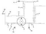
도 1은 체외 혈액 회로를 포함하는 혈액 투석 처리 시스템의 개략도이다.
도 2는 감시 장치에 연결된 체외 혈액 회로의 개략도이다.
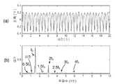
도 3의 (a)는 펌프 주파수 성분들 및 심장 신호 모두를 포함하는 정맥 압력 신호를 시간 영역으로 나타낸 그래프이고, (b)는 해당 신호를 주파수 영역으로 나타낸 그래프이다.
도 4는 혈액 회로의 무결성을 모니터링하는 프로세스의 흐름도이다.
도 5는 도 4의 프로세스를 실행하는 데이터 분석기의 블록선도이다.
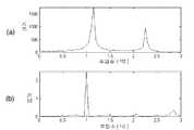
도 6의 (a) 및 (b)는 도 4에서의 데이터 분석기 내의 직접 검출 모듈에 의한 처리 전의 압력 신호 및 처리 후의 압력 신호의 파워 스펙트럼(power spectrum)을 보여주는 그래프들이다.
도 7은 혈액 펄스와 심장 펄스 간의 상이한 상대적 크기들에 대한, 직접 검출 모듈의 성능을 예시한 도면이다.
도 8의 (a) 및 (b)는, 심장 신호가 있는 경우에 그리고 심장 신호가 없는 경우에, 도 5의 데이터 분석기에서의 박동 검출 모듈에서의 처리 후의 압력 신호를 시간 영역으로 나타낸 그래프들이다.
도 9의 (a) 및 (b)는 도 8의 (a) 및 (b)의 그래프들을 확대하여 도시한 도면들이다.
도 10의 (a) 및 (b)는 도 9의 (a) 및 (b)의 데이터로부터 추출된 포락선들의 그래프들이다.
도 11은, 심장 신호가 있는 경우에 그리고 심장 신호가 없는 경우에, 포락선들로부터 계산된, 시간의 함수로서의 미분계수들의 합을 나타낸 그래프이다.
도 12는, 심장 신호가 있는 경우에 그리고 심장 신호가 없는 경우에, 포락선들로부터 계산된, 시간의 함수로서의 분산을 나타낸 그래프이다.
도 13은 혈액 펄스와 심장 펄스 간의 상이한 상대적 크기들에 대한, 박동 검출 모듈의 성능을 예시한 도면이다.
도 14는 혈액 펄스와 심장 펄스 간의 상이한 상대적 크기들에 대한, 조합된 직접 검출 모듈 및 박동 검출 모듈의 성능을 예시한 도면이다.
도 15는 압력 신호에서의 박동 성분의 검출을 위한 아날로그 장치들의 구성을 개략적으로 나타낸 도면이다.
도 16의 (a) 및 (b)는 본 발명의 실시예들을 사용하여 모니터링될 수 있는 유동 회로 구성들을 개략적으로 나타낸 도면들이다.1 is a schematic diagram of a hemodialysis treatment system including an extracorporeal blood circuit.
2 is a schematic diagram of an extracorporeal blood circuit connected to a monitoring device.
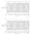
Figure 3 (a) is a graph showing the vein pressure signal including both the pump frequency components and the cardiac signal in the time domain, (b) is a graph showing the signal in the frequency domain.
4 is a flowchart of a process for monitoring the integrity of a blood circuit.
5 is a block diagram of a data analyzer executing the process of FIG.
6A and 6B are graphs showing a power spectrum of a pressure signal before processing and a pressure signal after processing by the direct detection module in the data analyzer of FIG. 4.
7 is a diagram illustrating the performance of the direct detection module for different relative magnitudes between blood pulses and heart pulses.
8A and 8B are graphs showing pressure signals in a time domain after processing in a rhythm detection module in the data analyzer of FIG. 5 in the presence of a heart signal and in the absence of a heart signal.
9A and 9B are enlarged views of the graphs of FIGS. 8A and 8B.
10A and 10B are graphs of envelopes extracted from the data of FIGS. 9A and 9B.
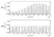
11 is a graph showing the sum of differential coefficients as a function of time, calculated from envelopes, with and without cardiac signal.
12 is a graph showing the variance as a function of time, calculated from envelopes, with and without cardiac signal.
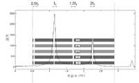
FIG. 13 is a diagram illustrating the performance of a rhythm detection module for different relative magnitudes between blood pulses and heart pulses.
14 is a diagram illustrating the performance of a combined direct detection module and a heartbeat detection module for different relative magnitudes between blood pulses and heart pulses.
FIG. 15 is a diagram schematically showing the configuration of analog devices for detection of a pulsating component in a pressure signal.
16A and 16B are schematic diagrams of flow circuit configurations that can be monitored using embodiments of the present invention.
이하에서는, 체외 혈액 처리와 관련하여 본 발명의 실시예들을 설명할 것이다. 그러나, 개시된 실시예들과 아울러 기초가 되는 발명의 개념들은, 본 설명을 끝맺는 부분에서 부가적으로 명시한 바와 같이 상기 설명과 관련된 분야 이외에도 적용가능하다.In the following, embodiments of the present invention will be described in connection with extracorporeal blood treatment. However, the concepts of the underlying invention in addition to the disclosed embodiments are applicable in addition to the fields related to the above description, as further indicated at the end of this description.
이하의 설명 전반에서는, 동일 요소들은 대응하는 참조번호들로 지시되어 있다.Throughout the description below, like elements are indicated by corresponding reference numerals.
도 1은 투석기에서 사용되는 타입의 체외 혈액 회로를 나타낸 도면이다. 상기 체외 혈액 회로는 동맥 바늘(1) 및 도 1에 도시된 바와 같이 튜브 연동 타입일 수 있는 혈액 펌프(3)에 동맥 바늘(1)을 연결하는 동맥 튜브 세그먼트(2)를 포함한다. 펌프의 입구 측에는 동맥 튜브 세그먼트(2)에서의 펌프 전의 압력을 측정하는 압력 센서(4a)(이하 '동맥 센서'라 지칭함)가 있다. 상기 혈액 펌프(3)는 튜브 세그먼트(5)를 통해 투석기(6)에 강제로 혈액을 전달한다. 여러 투석기들은 상기 혈액 펌프(3)와 상기 투석기(6) 간의 압력, 소위 시스템 압력을 측정하는 압력 센서(4b)를 추가로 구비하고 있다. 상기 혈액은 튜브 세그먼트(10)를 통해 상기 투석기(6)로부터 정맥 드립 챔버(drip chamber) 또는 탈기(脫氣) 챔버(11)로 안내되고, 다시 그로부터 정맥 튜브 세그먼트(12) 및 정맥 바늘(14)을 통해 상기 환자에게로 안내된다. 상기 챔버(11)는 상기 정맥 드립 챔버 내의 압력을 측정하는 압력 센서(4c)(이하 '정맥 센서'라 지칭함)를 구비하고 있다. 상기 동맥 바늘(1) 및 상기 정맥 바늘(14)은 혈관 액세스를 통해 상기 환자에게 연결되어 있다. 상기 혈관 액세스는 임의의 적합한 타입의 것, 예컨대 누공(fistula), 스크립너 션트(scribner-shunt), 하나 이상의 카테터들, 그래프트(graft) 등일 수 있다. 이하의 설명을 위해, 상기 혈관 액세스는 누공인 것으로 가정한다.1 shows an extracorporeal blood circuit of the type used in a dialysis machine. The extracorporeal blood circuit comprises an arterial needle (1) and an arterial tube segment (2) connecting the arterial needle (1) to a blood pump (3), which may be of the tube peristaltic type as shown in FIG. At the inlet side of the pump is a
혈액이, 상기 누공을 손상시키지 않을 정도의 작은 단면적을 갖는, 동맥 바늘(1)을 통과할 때, 압력이 주위 압력에 비해 대략 -200 내지 -50 mmHg로 낮아지는데, 이는 상기 동맥 센서(4a)로 측정된다. 압력은 상기 펌프(3)에서 상승하는데, 상기 압력은 상기 시스템 센서(4b)에 의해 측정된다. 상기 투석기(6)에서는, 내부의 유동 저항 때문에 압력이 떨어지고 상기 투석기 이후의 압력은 상기 정맥 센서(4c)로 측정되는데, 이러한 정맥 센서(4c)는 대개 상기 정맥 드립 챔버(11) 내의 압력을 측정하도록 연결되어 있다. 상기 정맥 드립 챔버(11) 내의 압력은 대개 +50 내지 +150 mmHg이다. 마지막으로, 상기 혈액이 정맥 바늘(14)을 통해 상기 누공으로 방출됨으로써, 상기 정맥 바늘 내에서는 그의 작은 단면적을 통한 유동 때문에 압력 강하가 생긴다.When blood passes through the
위에서 언급된 압력 상태들은 환자마다 상당히 다르고, 심지어 한 명의 동일한 환자에 대해서도 상이한 처리 세션들마다 다를 수 있으며, 뿐만 아니라 하나의 동일한 치료 세션 동안에도 다를 수 있다. 그러므로, 서로 다른 오류/오작동 상태들을 나타내도록, 압력 센서들에 대한 문턱값들을 설정하기가 어렵다. 여러 투석기들에서는, 상기 압력 검출기(4a-4c) 중 하나 이상의 검출기가 존재하지 않는다. 그러나, 적어도 하나의 정맥 압력 센서는 존재할 것이다. 도입부에서 설명한 바와 같이, 혈액 회로의 무결성을 모니터링하는 것이 절대적으로 필요할 수 있으며, 특히 상기 혈관 액세스를 통한 혈액의 주입 및/또는 추출의 오작동과 관련하여 혈관 액세스를 모니터링하는 것이 절대적으로 필요할 수 있다.The pressure states mentioned above vary considerably from patient to patient, even for different treatment sessions for one and the same patient, as well as for one and the same treatment session. Therefore, it is difficult to set thresholds for pressure sensors to indicate different error / malfunction conditions. In many dialyzers, no one or more of the
도 1에는 심장 펄스율을 측정하기 위해 환자에게 별도로 부착된 선택적인 펄스 미터(pulse meter; 30)가 부가적으로 도시되어 있다. 상기 펄스 미터(30)는 펄스 워치(pulse watch), 펄스 옥시미터(pulse oximeter), 심전계, 초음파 심장 진단도, 마이크로폰, 펄스 벨트 중 어느 하나일 수 있고, 혈량 측정법, 광 혈류량 검사(PPG), 혈압 커프, 또는 이들의 임의의 조합들 중 어느 형태일 수 있다.1 additionally shows an
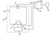
도 2는 상기 혈액 펌프(3) 및 [도 1에 도시된 센서들(4a-4c) 중 하나를 대표하는] 압력 센서(4)를 포함하는 체외 혈액 회로(20)의 또 다른 개략도를 예시한 도면이다. 제어 유닛(23)은 상기 혈액 펌프(3)의 회전 속도를 제어함으로써 상기 체외 혈액 회로(20) 내의 혈액 유동을 제어하도록 마련되어 있다. 상기 체외 혈액 회로(20) 및 상기 제어 유닛(23)은 투석기와 같은 체외 혈액 처리 장치(24)의 일부를 형성할 수 있다. 비록 부가적으로 도시되거나 설명되지는 않았지만, 이러한 혈액 처리 장치(24)가, 예컨대 투석액의 유동의 제어, 투석액의 온도 및 조성의 제어 등과 같은 여러 다른 기능들을 수행할 수 있다는 것을 이해할 것이다.2 illustrates another schematic diagram of an
감시/모니터링 장치(25)는 상기 체외 혈액 처리 장치(24)에 연결되어 있으며, 특히 혈압 신호 내에서 환자의 심장으로부터 발생하는 신호 성분의 존재를 모니터링함으로써 상기 체외 혈액 회로(20)의 무결성을 모니터링하도록 구성되어 있다. 그러한 신호 성분의 부재는 상기 체외 혈액 회로(20)의 무결성에서의 고장 표시로서 간주되며, 상기 감시 장치(25)가 알람을 활성화시키고/활성화시키거나 상기 혈액 펌프(3)를 중단시킴으로써 혈액 유동을 중단시키도록 한다. 상기 감시 장치(25)는 적어도 상기 체외 혈액 처리 장치(24)에 연결되어 상기 압력 센서(4)의 측정 신호를 나타내는 신호를 수신하게 된다. 도 2에 도시된 바와 같이, 상기 감시 장치(25)는 또한 상기 제어 유닛(23)에 연결되어 있을 수 있다. 대안으로 또는 추가적으로, 상기 감시 장치(25)는 상기 혈액 펌프(3)의 주파수를 나타내기 위한 측정 장치(26)에 연결되어 있을 수 있다. 상기 감시 장치(25)는 청각/시각/촉각 알람 또는 경보 신호를 발생시키기 위한 로컬 장치 또는 원격 장치(27)에 테더링 방식으로나 무선 방식으로 연결된다. 상기 감시 장치(25) 및/또는 알람 장치(27)는 대안으로 상기 체외 혈액 처리 장치(24)의 일부로서 통합되어 있을 수 있다.The monitoring /
도 2에서는, 상기 감시 장치(25)가, 예컨대 필요한 최소 샘플링율 및 분해능을 갖는 A/D 변환기, 하나 이상의 신호 증폭기들, 오프셋, 고주파 노이즈 및 공급 전압 외란들과 같은, 착신 신호(들)의 원하지 않는 성분들을 제거하도록 하는 하나 이상의 필터들을 포함하여, 착신 신호(들)을 사전처리하기 위한 데이터 획득부(28)를 포함한다.In FIG. 2, the
본원 명세서에서 제공된 예들에서는, 상기 데이터 획득부(28)는 샘플링율이 1 kHz이며 분해능이 16 비트인 National Instruments로부터 입수가능한 DAQ 카드 USB-6210, Analog Devices로부터 입수가능한 연산 증폭 회로 AD620, (신호 오프셋의 제거를 위해) 컷오프(cut-off) 주파수가 0.03 Hz인 하이패스 필터(highpass filter)와 아울러, (고주파 노이즈의 제거를 위해) 컷오프 주파수가 402 Hz인 로우패스 필터(lowpass filter)를 포함한다. 낮은 컨버전스 시간을 획득하기 위해, 고차 필터(3-4차)는 하이패스 필터용으로 사용된다. 더욱이, 상기 데이터 획득부(28)는, 분당 30 내지 160 박동의 심장 펄스율들에 해당하는, 상측 컷오프 주파수 및 하측 컷오프 주파수가 각각 0.5 Hz 및 2.7 Hz인, 추가적인 고정 대역 통과 필터를 포함할 수 있다. 이러한 필터는 관심 주파수 간격 외의 외란들을 억제하는 데 사용될 수 있다.In the examples provided herein, the
상기 데이터 획득부(28)에서의 사전처리 후에는, 상기 압력 센서(4)로부터의 신호가 입력으로서, 실제 모니터링 프로세스를 수행하는 데이터 분석부(29)에 제공된다. 도 3의 (a)는 시간 영역에서의 그러한 사전처리된 압력 신호의 일례를 보여주는 도면이며 (b)는 대응하는 파워 스펙트럼, 즉 주파수 영역에서의 압력 신호를 보여주는 도면이다. 상기 파워 스펙트럼은, 검출된 압력 신호가 상기 혈액 펌프(3)로부터 발생하는 다수의 상이한 주파수 성분들을 포함하고 있다는 것을 나타낸다. 예시된 예에서는, (본 예에서는 1.5 Hz인) 상기 혈액 펌프의 기저 주파수(fo)와 아울러, 그에 대한 조파(harmonics) 주파수들(2fo, 3fo 및 4fo)의 주파수 성분이 존재한다. 또한 이하에서 펌프 주파수로 나타낸 기저 주파수는 상기 체외 혈액 회로에서 압력파들을 발생시키는 펄스 스트로크들의 주파수이다. 예를 들면, 도 1에 도시된 유형의 연동식 펌프에서는, 회전자(rotor)의 각각의 완전 회전에 대해 2개의 펌프 스트로크가 발생된다. 도 3의 (b)는 또한 절반 펌프 주파수(0.5fo) 및 그에 대한 조파 주파수들, 본 예에서는 적어도 fo, 1.5fo, 2fo 및 2.5fo에서의 주파수 성분의 존재를 나타낸다. 도 3의 (b)는 또한 본 예에서 기저 주파수(fo)에서의 혈액 펌프 신호보다 대략 40배 약한 (1.1 Hz에서의) 심장 신호를 보여준다.After the preprocessing in the
이하에서 기술될 실시예들은 소정의 최소 반응 시간 내에서 상기 체외 혈액 회로(20)의 오작동을 검출하도록 설계된 것이다. 상기 압력 신호의 세그먼트들은 그러한 오작동을 검출하도록 상기 데이터 분석부(29)에 의해 분석된다. 긴 신호 세그먼트들은 모니터링 정확도를 높여주지만 반응 시간이 길어지게 한다. 이와는 반대로, 짧은 신호 세그먼트들은 반응 시간이 단축되지만, 모니터링 정확도의 저하를 초래한다. 절충안으로서, 상기 압력 신호는 오버래핑되는 일정 길이의 시간 윈도우에서 분석되는 것이 바람직하다. 다시 말하면, 오버래핑되는 신호 세그먼트들이 분석된다. 예를 들면, 상기 시간 윈도우는 연속 신호 세그먼트들이 단지 1초의 데이터에 대하여만 오버래핑하도록 착신 압력 신호에서 1초만큼 시프트될 수 있다. 본원 명세서에서 제공된 예들에서, 20초의 시간 윈도우가 분석 대상 신호 세그먼트들을 정의하기 위해 사용된다.Embodiments to be described below are designed to detect malfunction of the
일 변형예에서는, 상이한 길이의 신호 세그먼트들이 상기 체외 혈액 회로의 오작동을 검출하기 위해 처리/분석될 수 있다. 그러한 신호 세그먼트들은 오버래핑될 수도 있고 오버래핑되지 않을 수도 있다. 그 중 일 실시예에서, 신호 세그먼트(시간 윈도우)의 길이는, 예컨대 상기 혈액 펌프의 회전 속도 또는 펌프 주파수에 의해 제공되는, 혈액 유량의 함수로서 적합하게 설정될 수 있다. 예를 들면, 작은 혈액 유량에서는 잠재적인 오작동의 영향이 그다지 심하지 않을 수 있기 때문에, 상기 신호 세그먼트의 길이는 혈액 유량의 감소에 따라 길어질 수 있다. 다른 실시예에서는, 상이한 길이의 신호 세그먼트들이 상기 체외 혈액 회로의 오작동을 검출하도록 병렬로 또는 순차적으로 처리/분석될 수 있다. 예를 들면, 오작동을 검출하기 위해 검출 방법들의 조합이 사용될 때(예컨대, 도 4에 도시된 바와 같음. 이하 참조), 상이한 검출 방법들이 상이한 길이의 신호 세그먼트들에 대해 작동될 수 있다. 더욱이, 하나의 동일한 방법이 오작동을 검출하기 위해 평가 매개변수들의 조합을 사용하는 경우(예컨대 도 11 및 도 12에 도시된 바와 같음, 이하 참조), 상이한 평가 매개변수들이 상이한 길이의 신호 세그먼트들의 처리/분석에 의해 획득될 수 있다.In one variation, signal segments of different lengths may be processed / analyzed to detect malfunction of the extracorporeal blood circuit. Such signal segments may or may not overlap. In one embodiment, the length of the signal segment (time window) can be suitably set as a function of blood flow rate, eg provided by the rotational speed or pump frequency of the blood pump. For example, at small blood flow rates, the effects of potential malfunctions may not be so severe that the length of the signal segment may be lengthened with decreasing blood flow rate. In other embodiments, signal segments of different lengths may be processed / analyzed in parallel or sequentially to detect malfunctions of the extracorporeal blood circuit. For example, when a combination of detection methods are used to detect a malfunction (eg, as shown in Figure 4, see below), different detection methods may be operated on signal segments of different lengths. Moreover, when one and the same method uses a combination of evaluation parameters to detect malfunctions (e.g. as shown in Figures 11 and 12, see below), different evaluation parameters may be used to process signal segments of different lengths. Can be obtained by analysis.
도 4는 본 발명의 일 실시예에 따른 데이터 분석 또는 모니터링 프로세스에 대한 흐름도이다. 예시된 프로세스는 체외 혈액 회로의 무결성을 모니터링하도록 검출 방법들의 조합을 구현한다. 하나의 검출 방법("직접 검출")은 상기 압력 신호 내에서 환자의 심장으로부터 발생된 주파수 성분을 검출하는 단계를 포함한다. 다른 검출 방법("박동 검출")은 상기 압력 신호 내에서 진폭 변조(박동 신호)를 검출하는 단계를 포함하고, 상기 진폭 변조는 환자의 심장으로부터 발생된 압력파들과 상기 혈액 펌프로부터 발생된 압력파들 간의 간섭에 따른 것이다. 이와 같은 검출 방법들은 이하에서 더 상세히 설명되겠지만, 먼저 상기 프로세스의 전반적인 작동은 간략하게 요약될 것이다.4 is a flow diagram for a data analysis or monitoring process in accordance with one embodiment of the present invention. The illustrated process implements a combination of detection methods to monitor the integrity of extracorporeal blood circuits. One detection method (“direct detection”) includes detecting a frequency component generated from the patient's heart within the pressure signal. Another detection method (“beat detection”) includes detecting an amplitude modulation (beat signal) in the pressure signal, the amplitude modulation being generated by pressure waves generated from the patient's heart and pressure waves generated from the blood pump. It is due to interference between the liver. Such detection methods will be described in more detail below, but first the overall operation of the process will be briefly summarized.
상기 모니터링 프로세스는, 상기 압력 신호의 신호 세그먼트를 입력함과 아울러(단계 401), 상기 혈액 펌프의 기저 주파수(fo)에 관한 정보를 입력함으로써(단계 402) 개시된다. 이러한 주파수 정보는 상기 압력 신호 자체의 처리로부터 획득될 수 있다. 대안으로, 상기 주파수 정보는 전용 측정 장치(도 2의 참조번호 "26" 참조)에 의해 발생된 신호로부터 또는 상기 제어 유닛(도 2의 참조번호 "23" 참조)에 의해 사용되는 설정값 또는 실제값을 나타내는 신호로부터 획득될 수 있다. 단계 402가 상기 모니터링 프로세스의 모든 반복에 대해 수행될 필요가 없다는 것을 이해해야 한다.The monitoring process is initiated by inputting a signal segment of the pressure signal (step 401) and inputting information about the base frequency fo of the blood pump (step 402). This frequency information can be obtained from the processing of the pressure signal itself. Alternatively, the frequency information may be from a signal generated by a dedicated measuring device (see reference number "26" in FIG. 2) or from a set value or actual value used by the control unit (see reference number "23" in FIG. 2). It can be obtained from a signal representing a value. It should be understood that
상기 직접 검출 방법은 단계들 403-405를 포함하며, 이 경우에 상기 신호 세그먼트는 상기 혈액 펌프에 관련된 주파수 성분들(도 3에서의 0.5fo, fo, 1.5fo, 2fo, 2.5fo, 3fo 및 4fo 참조) 중 하나 이상의 주파수 성분들을 차단하도록 처리된다. 전형적으로, 단계 403은 상기 혈액 펌프로부터 발생된 모든 주파수 성분들로부터 신호 세그먼트를 효율적으로 "클리닝(cleaning)"하도록 설계된다. 단계 404에서는, 상기 환자의 심장으로부터 발생된 임의의 나머지 주파수 성분을 식별하기 위해 상기 신호 세그먼트를 주파수 영역에서 분석한다. 상기 심장 성분이 단계 405에서 검출되는 경우에는, 모니터링이 단계 401로 복귀되는데, 이 경우에는 새로운 압력 신호 세그먼트가 처리를 위해 입력된다. 위에서 언급된 바와 같이, 이러한 새로운 신호 세그먼트는 부분적으로 이전의 신호 세그먼트와 오버래핑될 수 있다. 어떠한 심장 성분도 단계 405에서 검출되지 않는 경우에는, 모니터링이 박동 검출로 진행한다. 심장 성분의 부재는, 체외 혈액 회로의 오작동으로부터 초래될 수도 있고, 너무 약하고/약하거나 상기 혈액 펌프의 주파수 성분들 중 임의의 주파수 성분에 너무 근접해 있는 심장 성분에 의해 초래될 수 있다.The direct detection method comprises steps 403-405, in which case the signal segment comprises frequency components associated with the blood pump (0.5fo , fo , 1.5fo , 2fo , 2.5f in FIG. 3).o , 3fo and 4fo ). Typically,
상기 박동 검출 방법은 단계들 406-408을 포함하는데, 이 경우에는, 각각 환자의 심장으로부터 발생된 압력파들과 상기 혈액 펌프로부터 발생된 압력파들 간의 간섭에 기인한 박동 신호를 식별하기 위해 상기 신호 세그먼트가 처리된다. 상기 박동 신호는 이와 같은 2가지의 압력파들 간의 주파수 차와 동일한 주파수를 갖는 신호 진폭의 주기적인 변동들로서 인식된다. 따라서, 상기 압력 신호 내에서 심장 펄스 자체를 탐색하는 대신에, 상기 박동 검출이 시간 영역에서의 압력 신호에 대한 심장 펄스의 효과들을 검사한다.The pulsation detection method includes steps 406-408, in which case the signal segment is for identifying a pulsating signal due to interference between pressure waves generated from the patient's heart and pressure waves generated from the blood pump, respectively. Is processed. The pulsating signal is recognized as periodic variations in signal amplitude with a frequency equal to the frequency difference between these two pressure waves. Thus, instead of searching for the heart pulse itself within the pressure signal, the heartbeat detection examines the effects of the heart pulse on the pressure signal in the time domain.
단계 406에서는, 하나 이상의 선택된 주파수 대역들을 제외한 모든 주파수들을 제거하기 위해 상기 신호 세그먼트를 처리한다. 그와 같이 각각 선택된 주파수 대역은 상기 혈액 펌프에 관련된 주파수 성분들(도 3에서의 0.5fo, fo, 1.5fo, 2fo, 2.5fo, 3fo 및 4fo 참조) 중 단지 하나의 주파수 성분을 포함하는 대역이다. 이러한 선택적 대역 통과(band pass) 필터링은 상기 박동 신호의 검출을 용이하게 하기 위해 수행될 수 있다. 상기 심장으로부터의 압력파는 상기 혈액 펌프로부터의 압력파보다 훨씬 작은(전형적으로는 20-200 배) 것이 일반적이어서, 잠재적인 박동파는 약한 것이고 아마도 검출하기가 어렵다. 전형적으로는, 그와 같이 선택된 하나의 주파수 대역 외의 모든 주파수들은 상기 신호 세그먼트로부터 제거되며, 그 때문에 결과적으로 얻어진 필터링된 신호 세그먼트는 박동 신호의 검출을 위해 시간 영역에서 분석된다(단계 407). 상기 혈액 펌프가 (도 3에 도시된 바와 같이) 다수의 주파수 성분들을 생성하는 것으로 알려져 있는 경우, 단계 406에 의해 한 세트의 필터링된 신호 세그먼트들을 얻게 되며, 각각의 필터링된 신호 세그먼트는 이러한 주파수 성분들 중 하나의 주파수 성분 주위의 주파수들만을 포함한다. 이와 같이 필터링된 신호 세그먼트들은 병렬로 생성된 다음에 단계 407에서 분석될 수 있다. 대안으로, 필터링된 신호 세그먼트들은 소정 순서의 혈액 펌프 주파수 성분들에 기반하여 순차적으로 생성될 수 있다. 각각의 필터링된 신호 세그먼트는 다른 필터링된 신호 세그먼트가 생성되기 전에 분석을 위해 단계 407로 진행될 수 있기 때문에, 박동 신호가 검출되면 곧 필터링된 신호 세그먼트들의 생성이 중단된다.In
또 다른 실시예에서는, 심장 펄스율이 알려져 있다. 그러한 경우에, 단계 406은 알려진 심장 주파수에 가장 근접해 있는 주파수 성분 주위의 주파수들만을 포함하는, 단지 하나의 필터링된 신호 세그먼트만의 생성으로 제한될 수 있다. 상기 심장 펄스율은, 상기 혈액 회로에 합체되거나 환자에 별도로 부착된, 도 1의 펄스 미터(30)에 의해 제공될 수 있다. 대안으로, 상기 심장 펄스율이 이전 단계 또는 동시적인 단계에서 획득될 수 있는데, 이 경우에 상기 압력 신호가 심장 주파수, 즉 심장 펄스율을 식별하기 위해 시간 영역 또는 주파수 영역에서 분석될 수 있다. 예를 들면, 상기 심장 주파수는 상기 모니터링 프로세스의 이전 반복에서 단계 406에 의해 획득될 수 있다. 선택적으로, 이러한 압력 신호는, 상기 혈액 펌프로부터 발생된 임의의 간섭 주파수 성분들을 제거하도록 혈액 펌프가 스위치오프되는 동안에 획득될 수 있다. 또 다른 변형예는 상기 혈액 회로 내의 또 다른 압력 센서로부터의 압력 신호를 분석함으로써 상기 심장 펄스율을 획득하는 것이다. 예를 들면, 상기 박동 검출 방법이 정맥 센서(도 1에서의 참조 번호 "4c")로부터의 압력 신호에 기반하는 경우에는, 상기 심장 펄스율이 동맥 센서(도 1에서의 참조 번호 "4a")로부터의 압력 신호로부터 획득될 수 있다. 여러 혈액 회로들에서는, 정맥측에 비해 동맥측에서, 심장으로부터의 압력파들이 더 강할 수 있고, 혈액 펌프로부터의 압력파들이 더 약할 수 있으며, 이에 따라 상기 동맥 센서로부터의 압력 신호에 기반한 심장 펄스율의 판단이 용이하게 된다.In another embodiment, cardiac pulse rates are known. In that case, step 406 may be limited to the generation of only one filtered signal segment, including only frequencies around the frequency component that is closest to the known cardiac frequency. The cardiac pulse rate may be provided by the
단계 406의 선택적 대역 통과 필터링은 주파수 대역(들)의 고정폭을 사용할 수 있는데, 이는 상기 박동 검출 방법의 원하는 성능, 전형적으로는 박동 신호를 초래하게 하는 펌프 주파수 성분 및 심장 펄스 간의 최대 주파수 간격을 고려하여 설정된다. 예를 들면, 상기 박동 검출 방법에 의해 사용되는 주파수 대역들은, 상기 박동 검출 방법이 이러한 주파수 성분들 간의 특정 주파수 영역들 내에서 심장 신호의 존재/부재를 검출하는 것이 가능한 다른 검출 방법(예컨대, 직접 검출 방법)과 조합하여 사용되는 경우에, 상기 펌프 주파수 성분들의 간격들에 비해 작을 수 있다. 다른 경우들에서는, 상기 주파수 대역들이 상기 펌프 주파수 성분들의 간격과 대략 동일한 전체 폭을 지닐 수 있거나, 인접한 펌프 주파수 성분들의 주파수 대역들이 심지어는 오버래핑될 수 있다. 다른 실시예에서, 주파수 대역(들)의 폭은, 이전에 결정된 심장 주파수의 함수로서 적합하게 설정될 수 있다. 예를 들면, 상기 폭은, 상기 심장 주파수가 펌프 주파수 성분들 중 하나의 펌프 주파수 성분에 근접함에 따라 감소될 수 있다. 위에서 언급된 바와 같이, 상기 심장 주파수는, 예컨대 개별 펄스율 미터, 다른 펄스 센서, 또는 상기 모니터링 프로세서의 이전 반복을 통해 획득될 수 있다.The selective bandpass filtering of
박동 신호가 단계 408에서 검출되는 경우, 상기 모니터링은 단계 401로 복귀되는데, 이 경우에 새로운 압력 신호 세그먼트가 처리를 위해 입력된다. 어떠한 박동 신호도 단계 408에서 검출되지 않는 경우, 상기 모니터링은 상기 혈액 회로의 오작동을 나타내는 알람, 또는 적어도 그러한 오작동이 일어났을 수 있다는 경보를 활성화시키도록 진행한다(단계 409). 상기 알람/경보의 활성화와 동시에, 상기 프로세스는 상기 펌프 주파수가 변경되는 단계 410으로 진행할 수 있는데, 이 때문에 상기 모니터링 프로세스는 상기 혈액 회로의 무결성을 계속 모니터링하기 위해 단계 401로 복귀할 수 있다. 심장 성분/박동 신호가 상기 모니터링 프로세스의 이후 반복(들) 동안에 발견되는 경우, 상기 알람/경보가 차단될 수 있다. 대안으로, 잘못된 알람들의 횟수를 최소화하기 위해, 단지 상기 모니터링 프로세스가 펌프 주파수의 그러한 변경 전후 모두에서 상기 심장 신호를 검출하지 못하는 경우에만 상기 알람/경보가 활성화될 수 있다.If a pulsating signal is detected in
단계 410의 일 실시예에서는, 펌프가 작동 상태로 유지되지만, 펌프의 펌프 주파수가 변경된다. 일 변형예에서, 상기 펌프 주파수는, 혈액 유동을 줄이기 위해 낮아지며, 이로 인해 검출되었던 잠재적인 오작동에 기인한 임의의 혈액 손실이 최소화된다. 다른 변형예에서는, 상기 펌프 주파수의 주파수 성분들이 그 이전 주파수 성분들과 불일치하도록 상기 펌프 주파수가 능동적으로 시프트된다. 예를 들면, 상기 기저 주파수가 상기 펌프로부터 발생된 주파수 성분들 간의 간격의 일부만큼 시프트될 수 있다. 도 3의 예에서, 이는 0.5fo 부분을 의미하는 것이다. 전형적으로는, 상기 시프트는 펌프 주파수의 감소를 나타낸다.In one embodiment of
단계 410의 다른 실시예에서는, 상기 펌프가 상기 혈액 펌프로부터의 간섭을 제거하면서 또한 검출되었던 잠재적인 오작동에 기인한 임의의 혈액 손실을 최소화하기 위해 차단된다(즉, fo = 0). 그러한 실시예의 변형에서, 단계 410은 또한 상기 혈액 펌프가 차단되는 동안에 상기 심장의 주파수를 식별한 다음, 이에 따라 식별된 심장 주파수로부터 시프트된 펌프 주파수로 상기 혈액 펌프를 재시동하는 단계를 포함한다. 상기 심장 주파수는, 예컨대 단계 404의 스펙트럼 신호 분석을 사용하여, 상기 압력 신호로부터 식별될 수 있다.In another embodiment of
단계 410의 추가적인 실시예에서, 상기 심작 펄스율은 예를 들면 도 1의 독립 소스(30)로부터 위에 기술된 바와 같이 알려져 있다. 상기 심장 펄스율은, 상기 체외 혈액 회로에 합체되어 있거나 환자에게 별도로 부착된, 펄스 미터(30)에 의해 제공될 수 있다. 그러한 실시예의 변형에서, 단계 410은 또한 상기 식별된 심장 주파수로부터 상기 혈액 펌프의 펌프 주파수를 시프트시키는 것을 포함한다. 따라서, 단계 410은 모든 관련 주파수 성분들이 상기 펄스 생성기의 주파수로부터 오프셋되게 하는 펌프 주파수를 가지고 상기 펌프 장치가 활성화되게 하는 것을 포함한다. 상기 펄스 미터(30)는 펄스 워치, 펄스 옥시미터, 심전계, 초음파 심장 진단도, 마이크로폰, 펄스 벨트 중 어느 하나일 수 있고, 혈량 측정법, 광 혈류량 검사(PPG), 혈압 커프, 또는 이들의 임의의 조합들 중 어느 형태일 수 있다.In a further embodiment of
도 5는 도 4에 도시된 모니터링 프로세스를 수행하도록 구성된 데이터 분석부(도 2에 도시된 참조 번호 "29" 참조)의 블록 선도이다. 상기 예시된 실시예에서는, 상기 데이터 분석부가 저장 블록(50), 펌프 주파수 결정 블록(51), 직접 검출 블록(52), 박동 검출 블록(53), 및 상기 직접 검출 블록(52) 및 상기 박동 검출 블록(53)의 출력을 알람 장치에 연결하기 위한 스위칭 블록(54, 55)을 포함한다. 비록 도시되어 있지는 않지만, 상기 블록들(50-55)의 동작을 동기화하기 위해 제어 블록이 제공될 수 있다.FIG. 5 is a block diagram of a data analyzer (see reference numeral “29” shown in FIG. 2) configured to perform the monitoring process shown in FIG. 4. In the illustrated embodiment, the data analyzing unit stores the
상기 데이터 분석부(29)는 범용 또는 전용 컴퓨터 장치 또는 프로그램된 마이크로프로세서와 같은 처리 장치에서 실행되는 소프트웨어로 구현될 수 있다. 상기 저장 블록(50)은 그러한 컴퓨터 장치의 휘발성 메모리 또는 비휘발성 메모리일 수 있는 반면, 다른 블록들(51-55)은 소프트웨어 명령어들에 의해 구현될 수 있다. 그러나, 일부 또는 모든 블록들이 당업계에 널리 공지되어 있는 바와 같이, FPGA, ASIC, 또는 개별 전자 부품들(레지스터들, 캐패시터들, 연산 증폭기, 트랜지스터들 등)의 조립체와 같은 전용 하드웨어에 의해 전체적으로 또는 부분적으로 구현될 수 있다.The data analyzer 29 may be implemented in software executed in a general purpose or dedicated computer device or a processing device such as a programmed microprocessor. The
상기 저장 블록(50)은 데이터 샘플들의 시퀀스로서 착신 압력 신호를 저장하도록 작동된다. 이때, 다른 블록들(51-53)은 상기 저장 블록(50)으로부터 저장된 압력 신호의 세그먼트들을 수신 또는 검색하도록 작동된다. 따라서, 상기 저장 블록(50)은 상기 착신 압력 신호를 버퍼링하여, 오버래핑 또는 비-오버래핑 신호 세그먼트들이 개별적으로 처리 및 분석되는 것을 허용한다. 상기 저장 블록(50)은, 예컨대 복수의 선형 버퍼들로서 또는 순환 버퍼(circular buffer)로서 구현될 수 있다.The
블록(51)은 신호 세그먼트에 기반하여 혈액 펌프의 주파수를 결정하도록 구성되어 있다. 그러한 블록에 의해 사용되는 알고리즘의 일례는 이하에서 부가적으로 기술될 것이다.
블록(52)은 펌프 주파수 결정 블록(51)에 의해 제공되는 추정된 펌프 주파수에 기반하여 직접 검출 단계들[단계 403-405(도 4)]을 구현한다. 상기 판단 단계 405의 결과가 부정적인 경우에, 다시 말하면 어떠한 심장 성분도 발견되지 않은 경우에, 스위칭 블록(54)은 블록(53)을 활성화시키도록 작동된다. 심장 성분이 발견되면 스위치 블록(54)은 상기 알람 장치에 긍정(positive) 상태 표시를 제공하도록 작동될 수 있고, 새로운 신호 세그먼트가 블록들(51, 52)에 의해 수신 또는 검색될 수 있다.
블록(53)은, 다시 추정된 펌프 주파수에 기반하여 박동 검출 단계들[단계 406-408 (도 4)]을 구현한다. 상기 판단 단계 408의 결과가 부정적인 경우에, 다시 말하면, 어떠한 박동 신호도 검출되지 않은 경우에, 상기 스위칭 블록(55)은 상기 알람 장치에 부정(negative) 상태 표시를 제공하여, 알람을 발생시키도록 작동된다. 박동 신호가 발견되는 경우에는, 스위칭 블록(55)이 상기 알람 장치에 긍정 상태 표시를 제공하도록 작동될 수 있으며, 새로운 신호 세그먼트가 상기 블록들(51, 52)에 의해 수신 또는 검색될 수 있다.
도 5에서는, 상기 데이터 분석부가 또한 [예컨대, 도 2에 도시된 측정 장치(26) 또는 제어 유닛(23)으로부터의] 펌프 주파수를 나타내는 신호를 수신하기 위한 입력부(56)를 포함한다. 단계 410(도 4)과 관련하여 언급된 바와 같이, 이러한 신호로부터 획득된 주파수 정보는 블록(51)에 의해 결정된 주파수를 보완 또는 대체할 수 있다.In FIG. 5, the data analyzer also includes an
도 5는 또한, 예컨대 단계 406 및/또는 단계 410의 실행시 블록(53)에 의해 사용될 환자의 심장 주파수를 나타내는 측정 신호에 대한 입력부(57)의 제공을 나타내고 있다.5 also shows the provision of an
상기 블록들(51-53) 각각에 대한 전형적인 작동은, 상기 펌프 주파수 결정 블록(51)으로부터 시작하여 이하 기술될 것이다.Typical operation for each of the blocks 51-53 will be described below, starting from the pump
상기 펌프 주파수 결정 블록(51)은 압력 신호 세그먼트로부터 파워 스펙트럼을 계산하도록 구성되고, 상기 파워 스펙트럼에서 상기 기저 펌프 주파수를 식별하도록 구성된다. 상기 파워 스펙트럼은, 예컨대 상기 압력 신호 세그먼트에 대해 DFT(Discrete Fourier Transform) 또는 FFT(Fast Fourier Transform)를 연산함으로써 임의의 공지된 방식으로 계산될 수 있다. 상기 기저 펌프 주파수가 상기 파워 스펙트럼에서 가장 큰 첨두값을 갖는 주파수로서, 또는 적어도 상기 가장 큰 첨두값들 중 하나로서 식별될 수 있다.The pump
상기 파워 스펙트럼의 분해능이 낮은 경우에, 상기 추정된 주파수의 정확도를 증가시키도록 특별 조치들이 채용될 수 있다. 상기 분해능은 상기 신호 세그먼트에서


상기 직접 검출 블록(52)은, 상기 혈액 펌프로부터 발생된 모든 주파수 성분들을 차단하도록, 압력 신호 세그먼트 상에서, 캐스케이드 결합되는 것이 전형적인 콤 필터(comb filter) 및/또는 대역 저지 필터(band-stop filter)들의 조합을 작동시키도록 구성될 수 있다. 대안으로, 그러한 차단은, 예컨대 앞서 언급된 WO 97/10013에 개시된 바와 같이 하나 이상의 적응 필터(adaptive filter)들의 사용에 의해 달성될 수 있다. 이때, 상기 직접 검출 블록(52)은, 예컨대 DFT 또는 FFT를 사용하여, 상기 필터링된 신호 세그먼트의 파워 스펙트럼을 계산하고, 상기 파워 스펙트럼에서의 가장 높은 첨두값을 식별하며, 그리고 이러한 첨두값이 충분한 의미를 갖는지의 여부를 평가한다. 예를 들면, 상기 첨두값(

이러한 관계가 소정 기준 레벨을 초과하는 경우에는, 심장 펄스가 존재하는 것으로 판단되며, 이와 다른 경우에는, 심장 펄스가 부재하는 것으로 판단된다. 이러한 기준 레벨은 (예컨대, 혈액 펌프의 기저 주파수에 의해 표시되는) 시스템 내의 상이한 유량들 간에 상이할 수 있다. 따라서, 직접 검출 블록(52)은 판단을 내리기 위해 기저 주파수들에 기준 레벨들을 관련시키는 데이터베이스에 액세스할 수 있다.If this relationship exceeds a predetermined reference level, it is determined that a heart pulse exists, and in other cases, it is determined that a heart pulse is absent. This reference level may differ between different flow rates in the system (eg, indicated by the base frequency of the blood pump). Thus, the
도 6의 (a)는 심장 펄스와 혈액 펌프 펄스 간의 상대적 크기가 1:60인, 1.13 Hz의 혈액 펌프 주파수 및 1 Hz의 심장 펄스에 대해 얻어진 압력 신호 세그먼트의 파워 스펙트럼을 도시한 것이고, 도 6의 (b)는 상기 직접 검출 블록에 의한 필터링 후의 동일한 신호 스펙트럼의 파워 스펙트럼을 도시한 것이다. 이러한 경우에, 상기 혈액 펌프의 주파수 성분들은 제거되며, 이로 인해 상기 심장 펄스 및 일부 노이즈가 남게 된다.FIG. 6A shows the power spectrum of the pressure signal segment obtained for a blood pump frequency of 1.13 Hz and a heart pulse of 1 Hz with a relative magnitude between heart pulse and blood pump pulse being 1:60, and FIG. 6 (B) shows the power spectrum of the same signal spectrum after filtering by the direct detection block. In this case, the frequency components of the blood pump are removed, leaving behind the heart pulse and some noise.
도 7은, 앞서 언급된 직접 검출 블록(52)을 사용하여 심장 펄스를 검출가능한 주파수 및 진폭 범위들의 일례이다. 점선으로 도시된 수직 라인들은 정상 심장의 주파수 범위를 나타내고, 수평 대역들은 심장 펄스가 1.13 Hz의 펌프 주파수를 사용하여 시스템 내에서 검출될 수 있는 주파수들을 나타낸다. 수평 대역들의 5개의 행들은, 하단 행에서부터 상단 행에 이르기까지 20:1, 40:1, 60:1, 80:1 및 100:1에 이르는 혈액 펌프와 심장 펄스들 간의 상이한 상대적 크기들을 나타낸다. 심장 신호가 상기 직접 검출 블록에서 검출가능하지 않은 혈액 펌프의 주파수 성분들 주변의 큰 영역이 존재하며, 이러한 영역은 상기 심장 펄스의 상대적 크기의 감소에 따라 넓어진다는 것은 분명하다.7 is an example of frequency and amplitude ranges that can detect a heart pulse using the aforementioned
상기 박동 검출 블록(53)은 한 세트의 통과 대역(pass band)들에 대해 상기 신호 세그먼트를 필터링하도록 구성되며, 각각의 통과 대역은 상기 혈액 펌프의 하나의 주파수 성분을 포함한다. 각각의 결과적인 필터링된 신호 세그먼트는 본질적으로 정현파이다. 상기 심장의 주파수가 이러한 통과 대역들 중 하나의 통과 대역 내에 있는 경우에는, 해당하는 필터링된 신호 세그먼트가 다른 필터링된 신호 세그먼트들 중 어느 하나에서 발견되지 않은 파형을 지니게 된다.The
도 8의 (a)는 1.5029 Hz에서의 혈액 펌프의 기저 주파수 주변의 좁은 대역 통과를 이용하여 필터링된 20초의 신호 세그먼트를 나타낸 것이다. 상기 필터링된 신호는 또한 심장 펄스를 포함하며, 이는 상기 기저 주파수에 대해 0.037 Hz의 주파수 시프트를 갖는다. 상기 혈액 펌프와 심장 펄스 간의 상대적 크기는 40:1이다. 도 8의 (b)는 심장 신호가 없는 경우에 해당하는 필터링된 신호 세그먼트를 나타낸 것이다. 비록 매우 작다 하더라도, 상기 신호 세그먼트들 간의 차이를 구별하는 것이 가능하며, 이 경우에 상기 심장의 존재로 인해, 도 8의 (b)에는 없는, 도 8의 (a)에 도시된 신호 진폭에서의 과도한 변화를 초래한다. 도 9의 (a) 및 (b)는, 심장 펄스가 있는 경우에 그리고 심장 펄스가 없는 경우에, 필터링된 신호 세그먼트들 간의 분명한 차이를 보여주는, 도 8의 (a) 및 (b)에서의 신호 첨두값들을 각각 확대하여 나타낸 도면들이다.8 (a) shows a 20 second signal segment filtered using narrow band pass around the base frequency of the blood pump at 1.5029 Hz. The filtered signal also includes a heart pulse, which has a frequency shift of 0.037 Hz relative to the base frequency. The relative magnitude between the blood pump and the heart pulse is 40: 1. 8 (b) shows the filtered signal segment corresponding to the absence of the heart signal. Although very small, it is possible to distinguish the difference between the signal segments, in which case due to the presence of the heart, in the signal amplitude shown in FIG. 8 (a), which is not present in FIG. It causes excessive change. 9 (a) and 9 (b) show the signal in FIGS. 8 (a) and (b), which shows a clear difference between the filtered signal segments, with and without heart pulses. Figures show enlarged peak values, respectively.
일 실시예에서, 상기 박동 검출 블록(53)은 상기 필터링된 신호 세그먼트로부터 획득된 포락선에 기반하여 박동 신호를 검출하도록 구성된다.In one embodiment, the
그러한 실시예의 변형에서, 상기 박동 검출 블록(53)은 상기 신호 세그먼트로부터 첨두값들의 어레이를 추출함으로써 상기 포락선을 획득한다. 상기 추출된 첨두값들은 상기 신호 세그먼트에서 식별된 개별 첨두의 신호값들을 추출함으로써 제공될 수 있다. 노이즈에 대한 강인성을 개선하기 위해, 각각의 추출된 첨두값은, 예컨대 상기 첨두값의 10%-25% 내의 신호값들 또는 상기 첨두값 주변의 소정 시간 범위 내의 신호값들을 포함하여, 상기 신호 세그먼트에서 각각의 첨두값을 형성하는 신호값들의 평균 또는 합으로서 대신 계산될 수 있다. 이때, 상기 획득된 포락선(첨두값 어레이)은 평가 매개변수의 계산을 위해 처리된다. 도 10의 (a) 및 (b)는 각각 도 9의 (a) 및 (b)로부터 추출된 첨두값의 어레이들을 나타낸 것이다.In a variation of such an embodiment, the
다른 변형에서, 블록(53)은 힐베르트(Hilbert) 변환기로서 알려져 있는 선형 시불변 필터를 신호 세그먼트(


상기 식 중,
개선된 처리 효율을 위해, 블록(53)은 이하의 식을 기반으로 상기 신호 세그먼트(


이때, 상기 획득된 포락선은, 근사한 것이든 아니든, 평가 매개변수의 계산을 위해 처리된다.At this time, the obtained envelope, whether approximate or not, is processed for the calculation of the evaluation parameters.
어느 일 변형예에서, 상기 획득된 포락선은 상기 평가 매개변수의 계산을 위해 처리되기 전에, 포락선 노이즈를 추가로 제거하기 위해 로우패스 필터링될 수 있다.In one variant, the obtained envelope may be lowpass filtered to further remove envelope noise, before being processed for the calculation of the evaluation parameter.
어느 일 변형예에서, 상기 평가 매개변수의 결과적인 값은 박동 신호의 존재 또는 부재를 판단하기 위해 문턱값과 비교될 수 있다.In one variant, the resulting value of the evaluation parameter may be compared with a threshold to determine the presence or absence of a pulsating signal.
일례에서는, 상기 평가 매개변수가 상기 포락선의 값들의 미분계수들의 절대 합이며, 이는 이하의 식으로 제공되고,In one example, the evaluation parameter is the absolute sum of the derivatives of the values of the envelope, which is given by

상기 식 중,


도 11은 1초의 시간에서 5분의 압력 신호에 걸쳐 20초의 윈도우를 이동시키고, 각각의 20초의 신호 세그먼트에 대해 획득된 포락선 상에서의 미분계수들의 절대 합을 계산한 결과를 예시한 도면이다. 상측 곡선은 심장 신호를 포함한 필터링된 신호 세그먼트에 대해 계산된 것이며, 하측 곡선은 심장 신호를 포함하지 않은 필터링된 신호 세그먼트에 대해 계산된 것이다. 문턱값이 심장 신호의 존재 및 부재를 구별하도록 정의될 수 있다는 것은 분명하다.FIG. 11 is a diagram illustrating the result of calculating the absolute sum of derivatives on the envelope obtained for each 20 second signal segment by moving a window of 20 seconds over a 5 minute pressure signal at a time of 1 second. The upper curve is calculated for the filtered signal segment that contains the cardiac signal and the lower curve is calculated for the filtered signal segment that does not include the cardiac signal. It is clear that the threshold can be defined to distinguish the presence and absence of a cardiac signal.
상기 상측 곡선은 상기 신호 세그먼트가 완전한 박동 신호 주기의 일부를 포함한다는 사실로 인한 파형을 나타낸다. 따라서, 시간 경과에 따라, 상기 신호 세그먼트들은 상기 박동 신호의 상이한 부분들을 포함하게 된다. 상기 포락선의 첨두부분들 및 골(valley)부분들 주변에서는 구배가 작고 상기 포락선의 첨두부분들 및 골부분들 사이에서는 구배가 더 크기 때문에, 상기 미분계수들의 계산된 합은 시간 경과에 따라 대응하여 변하게 된다. 상기 신호 세그먼트의 소정 길이(시간 윈도우)에 대해, 구배의 검출 가능성은 심장과 혈액 펌프 간의 주파수 차의 감소에 따라 감소하게 되는데, 그 이유는 이로 인해 박동 주파수가 낮아지고 상기 포락선이 편평하게 되기 때문이라는 것을 인식할 것이다. 더 넓은 시간 윈도우는, 박동의 진폭이 노이즈보다 작게 되는 시점까지 검출 가능성을 향상시켜 준다.The upper curve shows the waveform due to the fact that the signal segment contains part of the complete pulsating signal period. Thus, over time, the signal segments will contain different portions of the pulsating signal. Since the gradient is small around the peaks and valleys of the envelope and the gradient is greater between the peaks and valleys of the envelope, the calculated sum of the derivatives is correspondingly Will change. For a given length (time window) of the signal segment, the detectability of the gradient decreases as the frequency difference between the heart and the blood pump decreases, because this lowers the beat frequency and flattens the envelope. It will be recognized. A wider time window improves the detectability up to the point where the amplitude of the pulsations is smaller than the noise.
다른 예에서는, 상기 평가 매개변수가 상기 포락선의 값들의 분산이다. 도 12는 도 11에 대응하는 그래프이지만, 심장 신호가 있는 경우에(상측) 그리고 심장 신호가 없는 경우에(하측) 시간의 함수로서 분산을 예시한 도면이다. 문턱값이 심장 신호의 존재 및 부재를 구별하도록 정의될 수 있다는 것은 분명하다.In another example, the evaluation parameter is a variance of the values of the envelope. FIG. 12 is a graph corresponding to FIG. 11, but illustrating variance as a function of time in the presence of a heart signal (upper) and in the absence of a heart signal (lower). It is clear that the threshold can be defined to distinguish the presence and absence of a cardiac signal.
포락선 노이즈의 영향을 감소시킬 수 있는 또 다른 예에서는, 상기 평가 매개변수가 미분계수들의 평균 합이며, 예컨대 이하의 식으로 제공된다.In another example that can reduce the impact of envelope noise, the evaluation parameter is the average sum of the derivatives, for example provided by the following equation.

다른 실시예에서는, 상기 박동 검출 블록(53)이 패턴 인식 프로세싱에 기반하여 박동 신호의 존재 또는 부재를 판단한다. 예를 들면, 상기 포락선 또는 상기 신호 세그먼트의 일부 또는 모두가, 박동 신호를 나타내는 하나 이상의 소정 신호 패턴들에 매칭될 수 있다. 일례에서, (선택적으로는 로우패스 필터링되어) 획득된 포락선은 상이한 주파수들의 사인파들의 세트 각각의 사인파와 상호 상관되거나 이와는 달리 컨벌루션(convolution)될 수 있다. 각각의 상호 상관/컨벌루션은 결과적으로 상관 곡선을 초래하게 되며, 이로부터 최대 상관 값을 얻을 수 있다. 이때, 결과적인 세트의 최대 상관 값들은 박동 신호의 존재/부재를 판단하기 위한 문턱값과 비교될 수 있는데, 이 경우에 충분히 높은 최대 상관 값은 그러한 존재의 표시로서 간주될 수 있다.In another embodiment, the
박동 신호의 존재를 판단하는 위의 예들 모두는 상기 판단된 박동 신호의 신뢰성을 평가하는 추가적인 단계를 포함할 수 있다. 이러한 평가는 상기 박동 신호의 박동 주파수를 결정하고 이 박동 주파수가 적합한지를 체크하는 단계를 포함할 수 있다. 상기 박동 신호가 어떠한 방식으로 식별되는지에 따라, 시간/주파수 영역에서 획득된 포락선을 처리함으로써, 또는 최대 상관 값을 얻는 사인파의 주파수를 식별함으로써 상기 박동 주파수를 결정할 수 있다. 상기 박동 주파수는 상기 모니터링 프로세스(도 4)의 이전 반복들을 통해 결정된 하나 이상의 박동 주파수들에 관련하여 및/또는 절대 항(absolute term)들에서 체크될 수 있는데, 이 경우 이전 박동 주파수/주파수들로부터의 충분히 큰 편차는 상기 판단된 박동 신호가 신뢰할 수 없는 것이라는 표시로서 간주될 수 있다. 그러한 평가는 결과적으로 상기 판단된 박동 신호의 신뢰도를 나타내는 신뢰도 점수로 귀결될 수 있다. 대안으로 또는 추가로, 상기 신뢰도 평가는 펌프의 펌프 주파수를 변경하도록 상기 펌프를 제어하고 대응하는 변경이 상기 박동 신호에서 나타내는지를 체크하는 단계를 포함할 수 있다. 예를 들면, 상기 펌프 주파수는 약간 시프트될 수 있거나, 상기 펌프는 간헐적으로 중단(shut-down)될 수 있다. 상기 신뢰도 평가의 결과는 단계 409-410의 수행, 예컨대 알람/경보가 활성화되는지, 상기 알람/경보의 활성화 전에 상기 모니터링 프로세스의 추가적인 반복이 필요한지, 상기 펌프 주파수가 변경되어야 하는지 등에 영향을 줄 수 있다.All of the above examples of determining the presence of a pulsating signal may include an additional step of evaluating the reliability of the determined pulsating signal. Such evaluation may include determining the pulsing frequency of the pulsating signal and checking whether the pulsing frequency is suitable. Depending on how the pulsating signal is identified, the pulsing frequency can be determined by processing the envelope obtained in the time / frequency domain, or by identifying the frequency of the sine wave to obtain the maximum correlation value. The beat frequency may be checked in absolute terms and / or in relation to one or more beat frequencies determined through previous iterations of the monitoring process (FIG. 4), in which case from the previous beat frequency / frequency A sufficiently large deviation of can be considered as an indication that the determined pulsating signal is unreliable. Such evaluation may result in a reliability score that in turn indicates the reliability of the determined pulsating signal. Alternatively or additionally, the reliability assessment may include controlling the pump to change the pump frequency of the pump and checking whether a corresponding change is indicated in the pulsating signal. For example, the pump frequency may be shifted slightly, or the pump may be shut down intermittently. The results of the reliability assessment may affect the performance of steps 409-410, such as whether an alarm / alarm is activated, whether further monitoring of the monitoring process is required before the alarm / alarm is activated, whether the pump frequency should be changed, and so on. .
테스트들을 통해 상이한 평가 매개변수들이 상이한 경우들에 바람직할 수 있다는 것이 입증되었다. 예를 들면, 분산의 사용은 상기 조파 주파수들 중 하나의 주파수 주변의 박동 신호를 찾을 경우에 검출 가능성을 높여줄 수 있는 반면에, 미분계수들의 절대 합 또는 미분계수들의 평균 합의 사용은 상기 기저 주파수 주변의 박동 신호를 찾을 경우에 선호될 수 있다. 다른 검출 방법들이 실패한 경우에는 패턴 인식의 도움을 받을 수 있다. 따라서, 상기 박동 검출 블록(53)은 이러한 평가 매개변수들 중 하나 또는 임의의 조합을 사용하도록 구성될 수 있다.Tests have demonstrated that different evaluation parameters may be desirable in different cases. For example, the use of variance can increase the detectability when looking for a pulsating signal around one of the harmonic frequencies, whereas the use of an absolute sum of differential coefficients or an average sum of derivatives can result in the base frequency. This may be preferred when looking for a nearby pulsating signal. If other detection methods fail, the pattern recognition can be assisted. Thus, the
도 13은 상기 박동 검출 블록(53)을 사용하여 심장 펄스를 검출가능한 주파수 및 진폭 범위들의 일례이다. 점선들은 정상 심장의 주파수 범위를 나타낸 것이고, 어두운 수평 대역들은 1.13 Hz의 펌프 주파수를 사용하여 심장 펄스가 시스템에서 검출될 수 있는 주파수들을 나타낸 것이다. 수평 대역들의 5개의 열들은 하측 행에서부터 상측 행에 이르기까지 20:1, 40:1, 60:1, 80:1 및 100:1의 범위를 취하는, 혈액 펌프와 심장 펄스들 간의 상이한 상대적 크기들을 나타낸다. 도 7의 대응하는 그래프에 비하여, 사각 지대(blind zone)들이 훨씬 적은데, 이는 상기 혈액 펌프의 주파수 성분들, 특히 그 기저 주파수 및 대응하는 조파 주파수들 부근의 심장 펄스의 존재를 검출하고자 할 때 상기 박동 검출 방법이 상기 직접 검출 방법보다 우수하다는 것을 나타낸다.13 is an example of frequency and amplitude ranges capable of detecting a heart pulse using the
마지막으로, 도 14는 조합된 직접 검출 및 박동 검출을 사용하는, 도 5에서의 감시 장치의 성능을 예시한 도면이다. 밝은 대역들은 심장 검출이 상기 직접 검출 방법에 의해 이루어지는 주파수 영역들을 나타낸 것인 반면에, 어두운 대역들은 심장 검출이 박동 검출에 의해 이루어지는 주파수 영역들을 나타낸 것이다. 기법들의 조합을 통해, 각각의 주파수 영역들에서의 검출을 위한 직접 검출 방법 및 박동 검출 방법(도 4)을 개별적으로 최적화하는 것이 가능하다.Finally, FIG. 14 is a diagram illustrating the performance of the monitoring device in FIG. 5 using combined direct detection and pulsation detection. The bright bands represent the frequency regions where cardiac detection is made by the direct detection method, while the dark bands represent the frequency regions where cardiac detection is made by rhythm detection. Through a combination of techniques, it is possible to individually optimize the direct detection method and the pulsation detection method (FIG. 4) for detection in respective frequency domains.
주로 몇몇 실시예들을 참조하여 본 발명을 설명하였다. 그러나, 당업자라면 용이하게 이해할 수 있는 바와 같이, 위에 개시된 실시예들과는 다른 실시예들은, 첨부된 특허청구범위에 의해서만 정의되고 한정되는, 발명의 범위 및 사상 내에서 마찬가지로 가능하다.The invention has been described primarily with reference to some embodiments. However, as those skilled in the art will readily appreciate, embodiments other than the embodiments disclosed above are equally possible within the scope and spirit of the invention, which is defined and defined only by the appended claims.
예를 들면, 상기 압력 신호는, 예컨대 저항식 감지, 용량식 감지, 유도식 감지, 자기식 감지 또는 광 감지에 의해 작동하고, 하나 이상의 다이어프램, 벨로우즈, 부르돈 튜브(Bourdon tube), 압전 소자들, 반도체 부품들, 스트레인 게이지들, 공진 와이어들 등등을 사용하여 작동하는, 임의의 구상 가능한 타입의 압력 센서로부터 발생될 수 있다.For example, the pressure signal may be operated, for example, by resistive sensing, capacitive sensing, inductive sensing, magnetic sensing or light sensing, and one or more diaphragms, bellows, Bourdon tubes, piezoelectric elements. Can be generated from any conceivable type of pressure sensor, operating using semiconductor components, strain gauges, resonant wires, and the like.
더욱이, 상기 예시된 실시예들은, 혈액이 환자의 순환계로부터 취출되어 혈액이 상기 환자의 순환계로 복귀되기 전에 프로세스가 혈액에 적용되게 하는 모든 타입들의 체외 혈액 회로들의 감시를 위해 적용 가능하다. 그러한 혈액 회로들은 혈액 투석, 혈액 여과, 혈장 사혈, 아페레시스(apheresis), 체외 멤브레인 산소화, 보조 혈액 순환, 및 체외 간 지원/투석을 포함한다.Moreover, the illustrated embodiments are applicable for the monitoring of all types of extracorporeal blood circuits such that blood is withdrawn from the patient's circulatory system and the process is applied to the blood before the blood is returned to the patient's circulatory system. Such blood circuits include hemodialysis, blood filtration, plasma hemostasis, apheresis, extracorporeal membrane oxygenation, assisted blood circulation, and extracorporeal liver support / dialysis.
더욱이, 상기 모니터링 기법은, 위에서 개시된 바와 같은 회전형 연동 펌프들뿐만 아니라, 선형 연동 펌프들, 다이어프램 펌프들과 아울러 원심 펌프와 같은 다른 타입들의 용적식 유량 펌프들과 같이, 상기 혈액 회로에서 압력 펄스들을 발생시키는 임의의 타입의 혈액 펌프에도 적용가능하다.Moreover, the monitoring technique is a pressure pulse in the blood circuit, as well as rotary peristaltic pumps as disclosed above, as well as linear peristaltic pumps, diaphragm pumps and other types of volumetric flow pumps such as centrifugal pumps. Applicable to any type of blood pump that generates them.
당업자라면 본 발명의 모니터링 기법이 단지 박동 검출에 기반한 것일 수 있다고 용이하게 인식할 것이다. 선택적으로는, 박동 검출이, 위에서 언급된 직접 검출 방법 또는 도입부를 통해 기술된 바와 같은 문턱값들을 사용한 압력 레벨 검출과 같은 다른 검출 기법과 조합될 수 있다. 상기 조합된 검출 기법은 직렬로, 임의의 순서로, 또는 병렬로 수행될 수 있다.Those skilled in the art will readily recognize that the monitoring technique of the present invention may be based solely on heartbeat detection. Alternatively, pulsation detection can be combined with other detection techniques, such as pressure level detection using thresholds as described above or through the direct detection method mentioned above. The combined detection technique can be performed in series, in any order, or in parallel.
당업자는 상기 압력 신호에서 박동 신호를 검출하는 다른 방식들을 찾을 수 있을 것이다. 위에서 언급된 상기 혈액 펌프의 상이한 주파수 성분들 주변의 선택적 대역 통과 필터링은 박동 검출을 용이하게 하기 위해 포함되어 있지만, 제거될 수도 있다. 상기 박동 신호는 시간 영역에서 신호 세그먼트들을 분석함으로써 검출될 필요가 없다. 예를 들면, 상기 신호 세그먼트가 상기 박동 신호의 주기와 관련하여 길 경우에, 박동은, 예컨대 위에서 언급된 포락선의 푸리에 변환 다음에, 주파수 영역에서 검출가능할 수 있다.Those skilled in the art will find other ways of detecting the pulsating signal in the pressure signal. Selective band pass filtering around the different frequency components of the blood pump mentioned above is included to facilitate pulsation detection, but may be eliminated. The pulsating signal does not need to be detected by analyzing signal segments in the time domain. For example, if the signal segment is long with respect to the period of the pulsating signal, the pulsation may be detectable in the frequency domain, for example following the Fourier transform of the envelope mentioned above.
더군다나, 본 발명의 개념들이 디지털 신호 처리에 국한되는 것은 아니다. 도 15는 압력 신호 내에서의 박동 성분의 검출을 위한 아날로그 장치들의 전형적인 조합을 예시하고 있다. 개별 장치들은 그 자체로 공지되어 있고 변형적인 실시는 당업자라면 용이하게 이용가능하다. 아날로그 장치들의 예시적인 조합은, 상기 펌프 장치의 기저 주파수(fo)에서 신호 성분을 분리시키기 위해 착신 압력 신호를 필터링하도록 되어 있는 대역 통과 필터(151)를 포함한다. 주파수 체배기(152)는 상기 필터링된 압력 신호를 수신하도록 구성되어 있으며, 상기 기저 주파수의 선택된 배수(0.5, 1, 2.5, 3 등등)에서 해당 출력 신호를 발생시키도록 제어가능하다. 상기 주파수 체배기(152)로부터의 출력 신호는 제어가능한 대역 통과 필터(153)에 제어 신호로서 입력되며, 상기 제어가능한 대역 통과 필터(153)는 상기 착신 압력 신호를 수신하고 필터링하도록 되어 있다. 그리하여, 상기 제어가능한 대역 통과 필터(153)는 상기 주파수 체배기(152)로부터의 제어 신호의 주파수 주변의 주파수 대역을 제외한 모든 주파수를 제거함으로써(도 4에 도시된 단계 406 참조) 상기 압력 신호를 처리하도록 제어된다. 상기 처리된 압력 신호는 첨두값 검출기(154)에 입력되고, 상기 첨두값 검출기(154)는 이에 따라 포락선 신호를 발생시키는데, 이러한 포락선 신호는 다시금 상기 포락선 신호로부터 임의의 DC 성분을 제거하는 하이패스 필터(155)에 공급된다. 선택적으로, 상기 포락선 신호로부터 고주파 노이즈를 제거하기 위해 (도시되지 않은) 로우패스 필터가 포함될 수 있다. 마지막으로, 상기 포락선 신호는 박동 신호의 존재/부재를 판단하도록 되어 있는 진폭 검출기(156)에 의해 수신된다. 상기 진폭 검출기는, 순차적으로, 전파 정류기(full wave rectifier; 156a), 로우패스 필터(156b) 및 기준 신호로 공급되는 비교기(156c)를 포함할 수 있다. 상기 비교기(156c)에 대한 입력 신호의 진폭이 기준 신호를 초과할 경우에는, 상기 비교기(156c)가 박동 신호의 존재를 나타내는 신호를 출력할 수 있고, 그러하지 않을 경우에는 상기 비교기(156c)가 박동 신호의 부재를 나타내는 신호를 출력할 수 있다.Furthermore, the concepts of the present invention are not limited to digital signal processing. Figure 15 illustrates a typical combination of analog devices for the detection of pulsating components in a pressure signal. Individual devices are known per se and alternative implementations are readily available to those skilled in the art. An exemplary combination of analog devices includes a
위에 기재된 본 발명의 개념은 또한 혈액과는 다른 유체를 전달하기 위한 유동 회로들의 무결성을 모니터링하는 데 적용가능할 수 있다. 마찬가지로, 이러한 유동 회로들은 환자와 유체 연통될 필요는 없지만, 임의의 다른 타입의 수용기에 연결될 수 있다.The inventive concept described above may also be applicable for monitoring the integrity of flow circuits for delivering fluids other than blood. Likewise, these flow circuits need not be in fluid communication with the patient but can be connected to any other type of receptor.
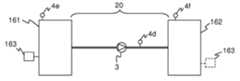
도 16의 (a)는 제1 수용기(161)로부터 제2 수용기(162)를 통해 다시 상기 제1 수용기(161)로 유체를 전달하도록 구성되는 유동 회로(20)를 예시한 것이다. 상기 제2 수용기(162)는 [도 1에 도시된 투석기(6)와 같이] 유체를 처리하도록 구성될 수 있다. 대안으로, 상기 제2 수용기(162)가 순환하는 유체에 의해 처리될 수 있다(청정, 정화, 소독 등). 펌프 장치(3)는 상기 유동 회로(20)에서 유체를 순환시킨다. 압력 센서(4d 또는 4e)는 상기 제1 수용기(161) 또는 상기 유동 회로(20) 내의 유체 압력을 표시하도록 구성된다. 펄스 생성기(163)는 내부 유체에서의 압력파들을 발생시키도록 상기 제1 수용기와 결합된다. 상기 펄스 생성기(163)는 예컨대, 펌프, 바이브레이터 등의 형태로 (환자의 심장과 마찬가지로) 상기 제1 수용기(161)에 고유한 것일 수 있다. 대안으로, 상기 펄스 생성기(163)은 바이브레이터, 초음파 생성기 등등와 같은, 상기 제1 수용기(161)에 부착된 개별적인 전용 장치일 수 있다. 상기 펄스 생성기(163)에 의해 발생된 압력파들과 상기 펌프 장치(3)에 의해 발생된 압력파들 간의 간섭은, 상기 유동 회로(20)에 연결된 압력 센서(44) 또는 상기 제1 수용기(161)에 연결된 압력 센서(4e) 중 어느 하나에 의해 검출되는 압력 신호에서 박동을 형성하게 된다. 위에서 기술된 바와 같이, 상기 압력 신호는 상기 압력 신호 내에서의 박동의 존재 또는 부재에 적어도 부분적으로 기반하여 상기 유동 회로(20)의 무결성을 판단하기 위한 모니터링 장치(도시되지 않음)에 의해 분석될 수 있다. 본원 명세서에 개시된 본 실시예, 및 다른 모든 실시예에서, 상기 모니터링 장치는 둘 이상의 압력 센서로부터의 압력 신호들을 통해 작동될 수 있다.FIG. 16A illustrates a
도 16의 (b)는 제1 수용기(161)로부터 일방향 경로를 따라 제2 수용기(162)로 유체를 전달하도록 구성된 유동 회로(20)를 예시한 것이다. 도 16의 (a)에서와 같이, 펄스 생성기(163)는 상기 제1 수용기(161)와 결합되어 있을 수 있으며, 상기 유동 회로의 무결성은 압력 신호 내에서의 박동의 존재 또는 부재에 적어도 부분적으로 기반하여 모니터링 장치(도시되지 않음)에 의해 판단될 수 있다. 상기 압력 신호는 상기 제1 수용기(161), 상기 유동 회로(20) 또는 상기 제2 수용기(162)에 연결된 압력 센서(4d-4f)에 의해 제공될 수 있다. 변형예에서, 상기 펄스 생성기(163)는 도 16의 (b)에 점선들로 나타낸 바와 같이, 상기 제2 수용기(162)와 결합될 수 있다.FIG. 16B illustrates a
도 16의 (a) 및 (b)의 구성들은, 상기 제2 수용기(162)에 전달되거나 상기 제2 수용기(162)를 통해 전달되는, 보통 액체인 임의의 타입의 유체와 함께 사용될 수 있다.The configurations of FIGS. 16A and 16B can be used with any type of fluid, usually liquid, delivered to or through the
그 중 일 실시예에서, 도 16의 (a)의 구성은, 혈액이 용기/머신(161)으로부터 혈액 처리 장치(162)를 통해 다시 상기 용기/머신(161)으로 펌핑되게 하는 유동 회로를 예시한 것이다. 비록 도 16의 (a)에 도시되어 있지 않지만, 혈액은 그 대신에 상기 혈액 처리 장치(162)의 하류에서 다른 용기/머신으로 향하게 될 수 있다. 상기 혈액 처리 장치(162)는 상기 혈액을 개질 및/또는 분석하도록 구성된 임의의 공지된 장치일 수 있다.In one embodiment, the configuration of FIG. 16A illustrates a flow circuit that allows blood to be pumped from the container /
추가적인 예에서, 상기 제2 수용기(162)는, 상기 제1 수용기(161)로부터 투석기(162)를 통해 선택적으로는, 적합한 화학약품들과 함께, 물을 펌핑함으로써 재처리되는 투석기이다. 상기 유동 회로는 도 16의 (a)에 도시된 바와 같이, 폐쇄될 수도 있고, 도 16의 (b)에 도시된 바와 같이 개방 종단(open-ended)될 수도 있다. 폐회로 투석기 재처리 시스템의 일례는 US2005/0051472에 공지되어 있다.In a further example, the
다른 예에서, 도 16의 (a)의 구성은, 투석액이 투석액 공급원(161)으로부터 투석액 재생 장치(162)를 통해 다시 투석액 공급원(161)로 순환되게 하는 투석액 재생 시스템의 일부를 도시한 것이다. 투석액 재생 장치의 일례는 WO 05/062973에 공지되어 있다.In another example, the configuration of FIG. 16A illustrates a portion of a dialysate regeneration system that causes the dialysate to be circulated from the
다른 예에서는, 도 16의 (a) 및 (b)는, 공급원(161)으로부터 상기 유동 회로(20)를 통해 투석기(162)로 프라이밍 유체(priming fluide)를 펌핑함으로써 체외 혈액 회로를 프라이밍하기 위한 구성들을 예시한 것이다. 상기 프라이밍 유체는, 예컨대 투석액, 염수, 정화된 물 등일 수 있다.In another example, FIGS. 16A and 16B illustrate a method for priming an extracorporeal blood circuit by pumping priming fluide from a
다른 예에서, 도 16의 (a) 및 (b)는, 청정 유체를 유동 경로(20)를 통해 투석기/투석기 튜브(162)로 펌핑함으로써 투석기의 투석액 유동 경로를 세척하고 소독하기 위한 구성들을 예시한 것이다. 세척액은 예컨대 고온의 물, 화학 용액 등일 수 있다.In another example, FIGS. 16A and 16B illustrate configurations for cleaning and disinfecting a dialysate flow path of a dialyzer by pumping clean fluid through the
추가적인 예에서, 도 16의 (a) 및 (b)는, 공급원(161)으로부터 정화 장치(162)를 통해 물을 펌핑함으로써 물을 정화하기 위한 구성들을 예시한 것이다. 상기 정화 장치(162)는, 예컨대, 역삼투, 탈이온화, 또는 탄소 흡수와 같은, 임의의 공지된 물 정화 기법을 사용할 수 있다.In a further example, FIGS. 16A and 16B illustrate configurations for purifying water by pumping water from a
다른 예에서, 도 16의 (a) 및 (b)는, 예컨대 내부의 투석액의 준비에 사용되도록 정화된 물을 투석기(162)에 제공하는 구성들을 예시한 것이다.In another example, FIGS. 16A and 16B illustrate configurations for providing the
이들 예들 모두에서, 그리고 동물 또는 사람의 환자들의 의학적 처리에 관련된 다른 용도에서, 상기 유동 회로(20)의 무결성을 모니터링하는 것은 절대적으로 필요할 수 있다. 그러한 모니터링은 본원 명세서에 개시된 발명의 개념에 따라 달성될 수 있다.In both of these examples, and in other uses related to the medical treatment of patients of animals or humans, it may be absolutely necessary to monitor the integrity of the
Claims (30)
Translated fromKorean압력 센서(4)로부터의 압력 신호를 수신하는 단계로서, 상기 압력 신호가 상기 수용기(161,162) 또는 상기 유동 회로(20) 내의 유체 압력을 나타내는 것인 단계;
상기 수용기(161,162)와 결합된 펄스 생성기(163)에 의해 발생된 압력파들과 상기 펌프 장치(3)에 의해 발생된 압력파들 간의 간섭에 의해 형성되는 박동 신호를 검출하기 위해 상기 압력 신호를 처리하는 단계; 및
상기 박동 신호의 존재 또는 부재에 적어도 부분적으로 기반하여 상기 유동 회로(20)의 무결성을 판단하는 단계;
를 포함하는 것인 유동 회로의 무결성에 대한 모니터링 방법.A method for monitoring the integrity of a flow circuit 20 in fluid communication with a receiver, the flow circuit 20 comprising a pump device 3 for delivering fluid through the flow circuit 20, the flow How to monitor the integrity of the circuit,
Receiving a pressure signal from a pressure sensor (4), wherein the pressure signal represents a fluid pressure in the receiver (161,162) or in the flow circuit (20);
Processing the pressure signal to detect a pulsating signal formed by interference between pressure waves generated by the pulse generator 163 coupled with the receivers 161 and 162 and pressure waves generated by the pump device 3. step; And
Determining the integrity of the flow circuit (20) based at least in part on the presence or absence of the pulsating signal;
Monitoring method for the integrity of the flow circuit comprising a.
상기 처리하는 단계는 상기 특정 주파수들 중 하나의 특정 주파수를 제외한 모든 특정 주파수들이 제거된 적어도 하나의 필터링된 압력 신호를 생성하는 것을 포함하는 것인 유동 회로의 무결성에 대한 모니터링 방법.The method according to claim 1 or 2, wherein the method for monitoring the integrity of the flow circuit further comprises obtaining one or more specific frequencies related to the pump frequency of the pump device (3),
And wherein said processing comprises generating at least one filtered pressure signal from which all particular frequencies except one of said particular frequencies have been removed.
상기 체외 혈액 유동 회로(20) 내의 압력 센서(4)로부터 압력 신호를 수신하는 단계;
각각 상기 환자의 심장에 의해 발생된 압력파들과 혈액 펌프 장치(3)에 의해 발생된 압력파들 간의 간섭에 의해 형성되는 박동 신호를 검출하기 위해 상기 압력 신호를 처리하는 단계; 및
상기 박동 신호의 존재 또는 부재에 적어도 부분적으로 기반하여 상기 체외 혈액 유동 회로(20)의 무결성을 판단하는 단계
를 포함하는 것인 체외 혈액 유동 회로의 무결성에 대한 모니터링 방법.A method of monitoring the integrity of an extracorporeal blood flow circuit 20 that is connected to a blood vessel of a patient, wherein the extracorporeal blood flow circuit 20 includes a blood pump device 3 and monitors the integrity of the extracorporeal blood flow circuit. Way,
Receiving a pressure signal from a pressure sensor (4) in the extracorporeal blood flow circuit (20);
Processing the pressure signal to detect a pulsating signal formed by interference between pressure waves generated by the heart of the patient and pressure waves generated by a blood pump device (3), respectively; And
Determining the integrity of the extracorporeal blood flow circuit 20 based at least in part on the presence or absence of the pulsating signal
Monitoring method for the integrity of the in vitro blood flow circuit.
압력 센서(4)로부터의 압력 신호를 위한 입력부로서, 상기 압력 신호는 상기 수용기(161,162) 또는 상기 유동 회로(20) 내의 유체 압력을 나타내는 것인 입력부; 및
상기 수용기(161,162)와 결합된 펄스 생성기(163)에 의해 발생된 압력파들과 상기 펌프 장치(3)에 의해 발생된 압력파들 간의 간섭에 의해 형성되는 박동 신호를 검출하기 위해 상기 압력 신호를 처리하도록 구성되는 제1 모듈(53)을 포함하는 신호 처리기(29)
를 포함하며, 상기 신호 처리기(29)는 상기 박동 신호의 존재 또는 부재에 적어도 부분적으로 기반하여 상기 유동 회로(20)의 무결성을 판단하도록 구성되는 것인 유동 회로의 무결성에 대한 모니터링 장치.A device for monitoring the integrity of the flow circuit 20 in fluid communication with the receivers 161, 162, the flow circuit 20 including a pump device 3 for delivering fluid through the flow circuit 20; The monitoring device for the integrity of the flow circuit,
An input for a pressure signal from a pressure sensor (4), the pressure signal representing a fluid pressure in the receiver (161, 162) or the flow circuit (20); And
To process the pressure signal to detect a pulsating signal formed by interference between the pressure waves generated by the pulse generator 163 coupled with the receivers 161, 162 and the pressure waves generated by the pump device 3. Signal processor 29 comprising a first module 53 configured
Wherein the signal processor (29) is configured to determine the integrity of the flow circuit (20) based at least in part on the presence or absence of the pulsating signal.
상기 펌프 장치(3)의 펌프 주파수에 관련된 하나 이상의 특정 주파수들을 획득하도록 구성되며, 그리고
상기 특정 주파수들 중 하나의 특정 주파수만을 제외한 모든 특정 주파수들이 제거된 적어도 하나의 필터링된 압력 신호를 생성하도록 구성되는 것인 유동 회로의 무결성에 대한 모니터링 장치.18. The method of claim 16 or 17, wherein the first module 53 is further
Is configured to obtain one or more specific frequencies related to the pump frequency of the pump device 3, and
And generate at least one filtered pressure signal from which all specific frequencies except only one of the particular frequencies are removed.
상기 펌프 장치(3)가 일시적으로 불활성화되게 하도록 구성되고,
상기 펄스 생성기(163)의 주파수를 식별하도록 구성되며, 그리고
모든 관련 주파수 성분들이 상기 펄스 생성기(163)의 주파수로부터 오프셋되게 하는 펌프 주파수로 상기 펌프 장치(3)가 활성화되게 하도록 구성되는 것인 유동 회로의 무결성에 대한 모니터링 장치.The signal processor 29 according to any one of claims 16 to 25,
Configured to temporarily deactivate the pump device 3,
And identify the frequency of the pulse generator 163, and
Monitoring the integrity of the flow circuit as configured to cause the pump arrangement (3) to be activated at a pump frequency such that all relevant frequency components are offset from the frequency of the pulse generator (163).
압력 센서(4)로부터의 압력 신호를 수신하는 수신 수단(28)으로서, 상기 압력 신호는 상기 수용기(161,162) 또는 상기 유동 회로(20) 내의 유체 압력을 나타내는 것인 수신 수단(28);
상기 수용기(161,162)와 결합된 펄스 생성기(163)에 의해 발생된 압력파들과 상기 펌프 장치(3)에 의해 발생된 압력파들 간의 간섭에 의해 형성되는 박동 신호를 검출하기 위해 상기 압력 신호를 처리하는 처리 수단(53); 및
상기 박동 신호의 존재 또는 부재에 적어도 부분적으로 기반하여 상기 유동 회로(20)의 무결성을 판단하는 판단 수단(53)
을 포함하는 것인 유동 회로의 무결성에 대한 모니터링 장치.A device for monitoring the integrity of the flow circuit 20 in fluid communication with the receivers 161, 162, the flow circuit 20 including a pump device 3 for delivering fluid through the flow circuit 20; The monitoring device for the integrity of the flow circuit,
Receiving means (28) for receiving a pressure signal from a pressure sensor (4), said pressure signal representing a fluid pressure in said receiver (161,162) or in said flow circuit (20);
Processing the pressure signal to detect a pulsating signal formed by interference between pressure waves generated by the pulse generator 163 coupled with the receivers 161 and 162 and pressure waves generated by the pump device 3. Processing means 53; And
Determining means 53 for determining the integrity of the flow circuit 20 based at least in part on the presence or absence of the pulsating signal
Monitoring apparatus for the integrity of the flow circuit comprising a.
상기 체외 혈액 유동 회로(20)에서의 압력 센서(4)로부터의 압력 신호를 수신하는 수신 수단(28);
상기 환자의 심장에 의해 발생된 압력파들과 상기 혈액 펌프 장치(3)에 의해 발생된 압력파들 간의 간섭에 의해 형성되는 박동 신호를 검출하기 위해 상기 압력 신호를 처리하는 처리 수단(53); 및
상기 박동 신호의 존재 또는 부재에 적어도 부분적으로 기반하여 상기 체외 혈액 유동 회로(20)의 무결성을 판단하는 판단 수단(53)
을 포함하는 것인 체외 혈액 유동 회로의 무결성에 대한 모니터링 장치.A device for monitoring the integrity of an extracorporeal blood flow circuit 20 connected to a blood vessel of a patient, wherein the extracorporeal blood flow circuit 20 includes a blood pump device 3 and a monitoring device for the integrity of the extracorporeal blood flow circuit. Is,
Receiving means (28) for receiving a pressure signal from a pressure sensor (4) in said extracorporeal blood flow circuit (20);
Processing means (53) for processing the pressure signal to detect a pulsating signal formed by interference between pressure waves generated by the patient's heart and pressure waves generated by the blood pump device (3); And
Determination means 53 for determining the integrity of the extracorporeal blood flow circuit 20 based at least in part on the presence or absence of the pulsating signal
Monitoring apparatus for the integrity of the blood flow circuit in vitro.
혈액 펌프 장치(3)를 포함하는 체외 혈액 유동 회로(20);
상기 체외 혈액 유동 회로(20) 내에 구성된 압력 센서(4); 및
제16항 내지 제28항 중 어느 한 항에 따른 모니터링 장치
를 포함하는 체외 혈액 치료 장치.As an extracorporeal blood treatment device,
An extracorporeal blood flow circuit 20 comprising a blood pump device 3;
A pressure sensor 4 configured in said extracorporeal blood flow circuit 20; And
29. Monitoring device according to any one of claims 16 to 28
In vitro blood treatment device comprising a.
Applications Claiming Priority (4)
| Application Number | Priority Date | Filing Date | Title |
|---|---|---|---|
| US4564208P | 2008-04-17 | 2008-04-17 | |
| SE0800890 | 2008-04-17 | ||
| US61/045,642 | 2008-04-17 | ||
| SE0800890-6 | 2008-04-17 |
Publications (2)
| Publication Number | Publication Date |
|---|---|
| KR20110005875Atrue KR20110005875A (en) | 2011-01-19 |
| KR101551512B1 KR101551512B1 (en) | 2015-09-08 |
Family
ID=40912074
Family Applications (1)
| Application Number | Title | Priority Date | Filing Date |
|---|---|---|---|
| KR1020107025747AExpired - Fee RelatedKR101551512B1 (en) | 2008-04-17 | 2009-04-16 | Method and devices for monitoring flow circuits |
Country Status (8)
| Country | Link |
|---|---|
| US (1) | US8718957B2 (en) |
| EP (1) | EP2307073B1 (en) |
| JP (1) | JP5587289B2 (en) |
| KR (1) | KR101551512B1 (en) |
| CN (1) | CN102006898B (en) |
| AU (1) | AU2009237654B2 (en) |
| CA (1) | CA2721444C (en) |
| WO (1) | WO2009127683A1 (en) |
Cited By (1)
| Publication number | Priority date | Publication date | Assignee | Title |
|---|---|---|---|---|
| US11458237B2 (en)* | 2017-04-10 | 2022-10-04 | Nikkiso Company Limited | Blood purification apparatus |
Families Citing this family (53)
| Publication number | Priority date | Publication date | Assignee | Title |
|---|---|---|---|---|
| US9026370B2 (en) | 2007-12-18 | 2015-05-05 | Hospira, Inc. | User interface improvements for medical devices |
| US10089443B2 (en) | 2012-05-15 | 2018-10-02 | Baxter International Inc. | Home medical device systems and methods for therapy prescription and tracking, servicing and inventory |
| KR101720823B1 (en)* | 2009-12-28 | 2017-03-28 | 감브로 룬디아 아베 | Apparatus and method for prediction of rapid symptomatic blood pressure decrease |
| EP2519278B1 (en)* | 2009-12-28 | 2015-01-28 | Gambro Lundia AB | Method and device for detecting a fault condition |
| WO2011080193A1 (en) | 2009-12-28 | 2011-07-07 | Gambro Lundia Ab | Method and device for monitoring the integrity of a connection system |
| EP2519279B1 (en) | 2009-12-28 | 2015-04-22 | Gambro Lundia AB | Device and method for monitoring a fluid flow rate in a cardiovascular system |
| ES2539821T3 (en) | 2009-12-28 | 2015-07-06 | Gambro Lundia Ab | Control of an apparatus for fluid transfer to and / or from a subject |
| ES2531951T3 (en) | 2009-12-28 | 2015-03-23 | Gambro Lundia Ab | Method and device to detect a configuration of withdrawal and return devices |
| WO2011080189A1 (en)* | 2009-12-28 | 2011-07-07 | Gambro Lundia Ab | Monitoring a property of the cardiovascular system of a subject |
| CN102946920B (en)* | 2010-04-14 | 2016-03-16 | 弗雷泽纽斯医疗保健德国有限公司 | Device and method for monitoring the connection of a blood treatment unit to a fluid system of an extracorporeal blood treatment apparatus |
| WO2012129501A2 (en) | 2011-03-23 | 2012-09-27 | Nxstage Medical, Inc. | Peritoneal dialysis systems, devices, and methods |
| US9427513B2 (en) | 2011-06-23 | 2016-08-30 | Gambro Lundia Ab | Detecting blood path disruption in extracorpreal blood processing |
| AU2012299169B2 (en) | 2011-08-19 | 2017-08-24 | Icu Medical, Inc. | Systems and methods for a graphical interface including a graphical representation of medical data |
| US10022498B2 (en) | 2011-12-16 | 2018-07-17 | Icu Medical, Inc. | System for monitoring and delivering medication to a patient and method of using the same to minimize the risks associated with automated therapy |
| JP6306566B2 (en) | 2012-03-30 | 2018-04-04 | アイシーユー・メディカル・インコーポレーテッド | Air detection system and method for detecting air in an infusion system pump |
| US9433365B1 (en)* | 2012-07-26 | 2016-09-06 | National Yang-Ming University | System and method for indentifying rotors in fractionated signals in persistent atrial fibrillation ablation |
| AU2013296555B2 (en) | 2012-07-31 | 2017-10-19 | Icu Medical, Inc. | Patient care system for critical medications |
| US20140163457A1 (en)* | 2012-12-07 | 2014-06-12 | Daniel M. Kelly | Gastric tube regulation system |
| AU2013360918B2 (en) | 2012-12-18 | 2017-10-19 | Gambro Lundia Ab | Detecting pressure pulses in a blood processing apparatus |
| CN104394899B (en) | 2012-12-20 | 2017-04-05 | 甘布罗伦迪亚股份公司 | Blood dial bundle LMS connecting detection |
| AU2014234479B2 (en) | 2013-03-20 | 2018-08-02 | Gambro Lundia Ab | Monitoring of cardiac arrest in a patient connected to an extracorporeal blood processing apparatus |
| DE102013008720B4 (en) | 2013-05-23 | 2019-05-09 | Fresenius Medical Care Deutschland Gmbh | Method and device for monitoring extracorporeal blood circulation |
| AU2014268355B2 (en) | 2013-05-24 | 2018-06-14 | Icu Medical, Inc. | Multi-sensor infusion system for detecting air or an occlusion in the infusion system |
| WO2014194065A1 (en) | 2013-05-29 | 2014-12-04 | Hospira, Inc. | Infusion system and method of use which prevents over-saturation of an analog-to-digital converter |
| US10166328B2 (en) | 2013-05-29 | 2019-01-01 | Icu Medical, Inc. | Infusion system which utilizes one or more sensors and additional information to make an air determination regarding the infusion system |
| US8960010B1 (en) | 2013-12-23 | 2015-02-24 | Fresenius Medical Care Holdings, Inc. | Automatic detection and adjustment of a pressure pod diaphragm |
| EP3110474B1 (en) | 2014-02-28 | 2019-12-18 | ICU Medical, Inc. | Infusion system and method which utilizes dual wavelength optical air-in-line detection |
| US11344673B2 (en) | 2014-05-29 | 2022-05-31 | Icu Medical, Inc. | Infusion system and pump with configurable closed loop delivery rate catch-up |
| KR102240494B1 (en)* | 2014-07-29 | 2021-04-16 | 현대모비스 주식회사 | Apparatus and Method for Object Detection |
| CA2957067C (en) | 2014-09-26 | 2019-02-19 | Fresenius Medical Care Holdings, Inc. | Pressure output device for extracorporeal hemodialysis machine |
| US11344668B2 (en) | 2014-12-19 | 2022-05-31 | Icu Medical, Inc. | Infusion system with concurrent TPN/insulin infusion |
| DE102015102040A1 (en)* | 2015-02-12 | 2016-08-18 | Fresenius Medical Care Deutschland Gmbh | A method of checking a connection state of a blood treatment device with a blood tubing set, and devices |
| US10850024B2 (en) | 2015-03-02 | 2020-12-01 | Icu Medical, Inc. | Infusion system, device, and method having advanced infusion features |
| JP6545485B2 (en) | 2015-03-10 | 2019-07-17 | 日機装株式会社 | Blood purification device |
| CA3023658C (en) | 2016-05-13 | 2023-03-07 | Icu Medical, Inc. | Infusion pump system and method with common line auto flush |
| WO2017214441A1 (en) | 2016-06-10 | 2017-12-14 | Icu Medical, Inc. | Acoustic flow sensor for continuous medication flow measurements and feedback control of infusion |
| CN106730170B (en)* | 2016-12-29 | 2020-05-29 | 广州天成医疗技术股份有限公司 | Injection pump back pumping method and device |
| US11179516B2 (en)* | 2017-06-22 | 2021-11-23 | Baxter International Inc. | Systems and methods for incorporating patient pressure into medical fluid delivery |
| EP3641850B1 (en) | 2017-06-24 | 2024-10-09 | NxStage Medical Inc. | Peritoneal dialysis fluid preparation systems |
| KR20200024855A (en)* | 2017-06-30 | 2020-03-09 | 백스터 인터내셔널 인코포레이티드 | Systems and Methods for Filtering Noise and Analyzing Vein Waveform Signals |
| US10089055B1 (en) | 2017-12-27 | 2018-10-02 | Icu Medical, Inc. | Synchronized display of screen content on networked devices |
| US10765790B2 (en) | 2018-02-20 | 2020-09-08 | Medtronic, Inc. | Detection of pump thrombosis |
| JP2021516089A (en) | 2018-02-28 | 2021-07-01 | ネクステージ メディカル インコーポレイテッド | Fluid preparation and treatment equipment, methods, and systems |
| CN110319978A (en)* | 2018-03-29 | 2019-10-11 | 深圳市水务(集团)有限公司 | Valve airtightness detection method, device, terminal device and storage medium |
| US11614456B2 (en)* | 2018-12-21 | 2023-03-28 | Pratt & Whitney Canada Corp. | System and method for engine speed measurement |
| KR20250047829A (en)* | 2019-10-30 | 2025-04-04 | 보스톤 싸이언티픽 리미티드 | fluid management and medical device system |
| DE102019133075A1 (en)* | 2019-12-04 | 2021-06-10 | B.Braun Avitum Ag | Blood treatment machine and method for automatic level monitoring and control of an air separator by means of frequency analysis |
| US11278671B2 (en) | 2019-12-04 | 2022-03-22 | Icu Medical, Inc. | Infusion pump with safety sequence keypad |
| CA3189781A1 (en) | 2020-07-21 | 2022-01-27 | Icu Medical, Inc. | Fluid transfer devices and methods of use |
| US11135360B1 (en) | 2020-12-07 | 2021-10-05 | Icu Medical, Inc. | Concurrent infusion with common line auto flush |
| USD1091564S1 (en) | 2021-10-13 | 2025-09-02 | Icu Medical, Inc. | Display screen or portion thereof with graphical user interface for a medical device |
| CA3241894A1 (en) | 2021-12-10 | 2023-06-15 | Icu Medical, Inc. | Medical fluid compounding systems with coordinated flow control |
| CN116147855B (en)* | 2022-12-02 | 2025-06-13 | 深圳核心医疗科技股份有限公司 | Inspection tooling |
Family Cites Families (8)
| Publication number | Priority date | Publication date | Assignee | Title |
|---|---|---|---|---|
| US4710163A (en) | 1986-06-06 | 1987-12-01 | Ivac Corporation | Detection of fluid flow faults in the parenteral administration of fluids |
| SE508374C2 (en)* | 1995-09-12 | 1998-09-28 | Gambro Med Tech Ab | Method and apparatus for detecting the condition of a blood vessel access |
| DE19901078C1 (en) | 1999-01-14 | 2000-02-17 | Polaschegg Hans Dietrich | Monitoring system for fistula or graft has instruments to detect pulse from patient's heart or external blood circulation pump |
| DE10159620C1 (en) | 2001-12-05 | 2003-08-14 | Fresenius Medical Care De Gmbh | Method and device for monitoring the supply of substitution fluid during extracorporeal blood treatment |
| WO2005004950A1 (en)* | 2003-07-10 | 2005-01-20 | Nikkiso Co., Ltd. | Pulse count measuring method, blood pressure measuring method, and blood vessel access monitoring method, and medical device using them |
| US20050051472A1 (en) | 2003-09-10 | 2005-03-10 | Willie Chionh | Dialyzer reprocessing system |
| US7435342B2 (en) | 2003-12-24 | 2008-10-14 | Chemica Technologies, Inc. | Dialysate regeneration system for portable human dialysis |
| ATE468870T1 (en)* | 2005-07-01 | 2010-06-15 | Gambro Lundia Ab | DEVICE FOR TESTING A FILTER |
- 2009
- 2009-04-16USUS12/988,146patent/US8718957B2/enactiveActive
- 2009-04-16AUAU2009237654Apatent/AU2009237654B2/ennot_activeCeased
- 2009-04-16WOPCT/EP2009/054514patent/WO2009127683A1/enactiveApplication Filing
- 2009-04-16JPJP2011504461Apatent/JP5587289B2/ennot_activeExpired - Fee Related
- 2009-04-16EPEP09732184.8Apatent/EP2307073B1/enactiveActive
- 2009-04-16KRKR1020107025747Apatent/KR101551512B1/ennot_activeExpired - Fee Related
- 2009-04-16CNCN2009801136275Apatent/CN102006898B/enactiveActive
- 2009-04-16CACA2721444Apatent/CA2721444C/ennot_activeExpired - Fee Related
Cited By (1)
| Publication number | Priority date | Publication date | Assignee | Title |
|---|---|---|---|---|
| US11458237B2 (en)* | 2017-04-10 | 2022-10-04 | Nikkiso Company Limited | Blood purification apparatus |
Also Published As
| Publication number | Publication date |
|---|---|
| EP2307073A1 (en) | 2011-04-13 |
| US20110040502A1 (en) | 2011-02-17 |
| WO2009127683A1 (en) | 2009-10-22 |
| CN102006898A (en) | 2011-04-06 |
| CN102006898B (en) | 2013-07-03 |
| JP2011516229A (en) | 2011-05-26 |
| KR101551512B1 (en) | 2015-09-08 |
| AU2009237654A1 (en) | 2009-10-22 |
| CA2721444C (en) | 2016-08-09 |
| JP5587289B2 (en) | 2014-09-10 |
| CA2721444A1 (en) | 2009-10-22 |
| AU2009237654B2 (en) | 2014-03-27 |
| EP2307073B1 (en) | 2015-07-22 |
| US8718957B2 (en) | 2014-05-06 |
Similar Documents
| Publication | Publication Date | Title |
|---|---|---|
| KR101551512B1 (en) | Method and devices for monitoring flow circuits | |
| US11300474B2 (en) | Methods and devices for monitoring the integrity of a fluid connection | |
| US9632018B2 (en) | Method and device for monitoring the integrity of a connection system | |
| US9427513B2 (en) | Detecting blood path disruption in extracorpreal blood processing | |
| AU2014253574B2 (en) | Methods and devices for monitoring the integrity or a fluid connection |
Legal Events
| Date | Code | Title | Description |
|---|---|---|---|
| PA0105 | International application | St.27 status event code:A-0-1-A10-A15-nap-PA0105 | |
| PG1501 | Laying open of application | St.27 status event code:A-1-1-Q10-Q12-nap-PG1501 | |
| R18-X000 | Changes to party contact information recorded | St.27 status event code:A-3-3-R10-R18-oth-X000 | |
| A201 | Request for examination | ||
| P11-X000 | Amendment of application requested | St.27 status event code:A-2-2-P10-P11-nap-X000 | |
| P13-X000 | Application amended | St.27 status event code:A-2-2-P10-P13-nap-X000 | |
| PA0201 | Request for examination | St.27 status event code:A-1-2-D10-D11-exm-PA0201 | |
| P11-X000 | Amendment of application requested | St.27 status event code:A-2-2-P10-P11-nap-X000 | |
| P13-X000 | Application amended | St.27 status event code:A-2-2-P10-P13-nap-X000 | |
| P11-X000 | Amendment of application requested | St.27 status event code:A-2-2-P10-P11-nap-X000 | |
| P13-X000 | Application amended | St.27 status event code:A-2-2-P10-P13-nap-X000 | |
| R17-X000 | Change to representative recorded | St.27 status event code:A-3-3-R10-R17-oth-X000 | |
| R17-X000 | Change to representative recorded | St.27 status event code:A-3-3-R10-R17-oth-X000 | |
| E701 | Decision to grant or registration of patent right | ||
| PE0701 | Decision of registration | St.27 status event code:A-1-2-D10-D22-exm-PE0701 | |
| GRNT | Written decision to grant | ||
| PR0701 | Registration of establishment | St.27 status event code:A-2-4-F10-F11-exm-PR0701 | |
| PR1002 | Payment of registration fee | St.27 status event code:A-2-2-U10-U12-oth-PR1002 Fee payment year number:1 | |
| PG1601 | Publication of registration | St.27 status event code:A-4-4-Q10-Q13-nap-PG1601 | |
| LAPS | Lapse due to unpaid annual fee | ||
| PC1903 | Unpaid annual fee | St.27 status event code:A-4-4-U10-U13-oth-PC1903 Not in force date:20180903 Payment event data comment text:Termination Category : DEFAULT_OF_REGISTRATION_FEE | |
| PC1903 | Unpaid annual fee | St.27 status event code:N-4-6-H10-H13-oth-PC1903 Ip right cessation event data comment text:Termination Category : DEFAULT_OF_REGISTRATION_FEE Not in force date:20180903 | |
| R18-X000 | Changes to party contact information recorded | St.27 status event code:A-5-5-R10-R18-oth-X000 | |
| P22-X000 | Classification modified | St.27 status event code:A-4-4-P10-P22-nap-X000 |