KR20110002156A - Novel compound and organic electronic device using same - Google Patents
Novel compound and organic electronic device using sameDownload PDFInfo
- Publication number
- KR20110002156A KR20110002156AKR1020090059601AKR20090059601AKR20110002156AKR 20110002156 AKR20110002156 AKR 20110002156AKR 1020090059601 AKR1020090059601 AKR 1020090059601AKR 20090059601 AKR20090059601 AKR 20090059601AKR 20110002156 AKR20110002156 AKR 20110002156A
- Authority
- KR
- South Korea
- Prior art keywords
- group
- unsubstituted
- substituted
- compound
- formula
- Prior art date
- Legal status (The legal status is an assumption and is not a legal conclusion. Google has not performed a legal analysis and makes no representation as to the accuracy of the status listed.)
- Granted
Links
Images


Classifications
- C—CHEMISTRY; METALLURGY
- C07—ORGANIC CHEMISTRY
- C07D—HETEROCYCLIC COMPOUNDS
- C07D221/00—Heterocyclic compounds containing six-membered rings having one nitrogen atom as the only ring hetero atom, not provided for by groups C07D211/00 - C07D219/00
- C07D221/02—Heterocyclic compounds containing six-membered rings having one nitrogen atom as the only ring hetero atom, not provided for by groups C07D211/00 - C07D219/00 condensed with carbocyclic rings or ring systems
- C07D221/20—Spiro-condensed ring systems
- C—CHEMISTRY; METALLURGY
- C07—ORGANIC CHEMISTRY
- C07D—HETEROCYCLIC COMPOUNDS
- C07D221/00—Heterocyclic compounds containing six-membered rings having one nitrogen atom as the only ring hetero atom, not provided for by groups C07D211/00 - C07D219/00
- C07D221/02—Heterocyclic compounds containing six-membered rings having one nitrogen atom as the only ring hetero atom, not provided for by groups C07D211/00 - C07D219/00 condensed with carbocyclic rings or ring systems
- C07D221/04—Ortho- or peri-condensed ring systems
- C07D221/18—Ring systems of four or more rings
- C—CHEMISTRY; METALLURGY
- C07—ORGANIC CHEMISTRY
- C07D—HETEROCYCLIC COMPOUNDS
- C07D239/00—Heterocyclic compounds containing 1,3-diazine or hydrogenated 1,3-diazine rings
- C07D239/70—Heterocyclic compounds containing 1,3-diazine or hydrogenated 1,3-diazine rings condensed with carbocyclic rings or ring systems
- C—CHEMISTRY; METALLURGY
- C07—ORGANIC CHEMISTRY
- C07D—HETEROCYCLIC COMPOUNDS
- C07D401/00—Heterocyclic compounds containing two or more hetero rings, having nitrogen atoms as the only ring hetero atoms, at least one ring being a six-membered ring with only one nitrogen atom
- C07D401/02—Heterocyclic compounds containing two or more hetero rings, having nitrogen atoms as the only ring hetero atoms, at least one ring being a six-membered ring with only one nitrogen atom containing two hetero rings
- C07D401/04—Heterocyclic compounds containing two or more hetero rings, having nitrogen atoms as the only ring hetero atoms, at least one ring being a six-membered ring with only one nitrogen atom containing two hetero rings directly linked by a ring-member-to-ring-member bond
- C—CHEMISTRY; METALLURGY
- C07—ORGANIC CHEMISTRY
- C07D—HETEROCYCLIC COMPOUNDS
- C07D401/00—Heterocyclic compounds containing two or more hetero rings, having nitrogen atoms as the only ring hetero atoms, at least one ring being a six-membered ring with only one nitrogen atom
- C07D401/02—Heterocyclic compounds containing two or more hetero rings, having nitrogen atoms as the only ring hetero atoms, at least one ring being a six-membered ring with only one nitrogen atom containing two hetero rings
- C07D401/10—Heterocyclic compounds containing two or more hetero rings, having nitrogen atoms as the only ring hetero atoms, at least one ring being a six-membered ring with only one nitrogen atom containing two hetero rings linked by a carbon chain containing aromatic rings
- C—CHEMISTRY; METALLURGY
- C07—ORGANIC CHEMISTRY
- C07D—HETEROCYCLIC COMPOUNDS
- C07D471/00—Heterocyclic compounds containing nitrogen atoms as the only ring hetero atoms in the condensed system, at least one ring being a six-membered ring with one nitrogen atom, not provided for by groups C07D451/00 - C07D463/00
- C07D471/02—Heterocyclic compounds containing nitrogen atoms as the only ring hetero atoms in the condensed system, at least one ring being a six-membered ring with one nitrogen atom, not provided for by groups C07D451/00 - C07D463/00 in which the condensed system contains two hetero rings
- C07D471/04—Ortho-condensed systems
- C—CHEMISTRY; METALLURGY
- C09—DYES; PAINTS; POLISHES; NATURAL RESINS; ADHESIVES; COMPOSITIONS NOT OTHERWISE PROVIDED FOR; APPLICATIONS OF MATERIALS NOT OTHERWISE PROVIDED FOR
- C09K—MATERIALS FOR MISCELLANEOUS APPLICATIONS, NOT PROVIDED FOR ELSEWHERE
- C09K11/00—Luminescent, e.g. electroluminescent, chemiluminescent materials
- C09K11/06—Luminescent, e.g. electroluminescent, chemiluminescent materials containing organic luminescent materials
- H—ELECTRICITY
- H10—SEMICONDUCTOR DEVICES; ELECTRIC SOLID-STATE DEVICES NOT OTHERWISE PROVIDED FOR
- H10K—ORGANIC ELECTRIC SOLID-STATE DEVICES
- H10K30/00—Organic devices sensitive to infrared radiation, light, electromagnetic radiation of shorter wavelength or corpuscular radiation
- H—ELECTRICITY
- H10—SEMICONDUCTOR DEVICES; ELECTRIC SOLID-STATE DEVICES NOT OTHERWISE PROVIDED FOR
- H10K—ORGANIC ELECTRIC SOLID-STATE DEVICES
- H10K50/00—Organic light-emitting devices
- Y—GENERAL TAGGING OF NEW TECHNOLOGICAL DEVELOPMENTS; GENERAL TAGGING OF CROSS-SECTIONAL TECHNOLOGIES SPANNING OVER SEVERAL SECTIONS OF THE IPC; TECHNICAL SUBJECTS COVERED BY FORMER USPC CROSS-REFERENCE ART COLLECTIONS [XRACs] AND DIGESTS
- Y02—TECHNOLOGIES OR APPLICATIONS FOR MITIGATION OR ADAPTATION AGAINST CLIMATE CHANGE
- Y02E—REDUCTION OF GREENHOUSE GAS [GHG] EMISSIONS, RELATED TO ENERGY GENERATION, TRANSMISSION OR DISTRIBUTION
- Y02E10/00—Energy generation through renewable energy sources
- Y02E10/50—Photovoltaic [PV] energy
- Y02E10/549—Organic PV cells
- Y—GENERAL TAGGING OF NEW TECHNOLOGICAL DEVELOPMENTS; GENERAL TAGGING OF CROSS-SECTIONAL TECHNOLOGIES SPANNING OVER SEVERAL SECTIONS OF THE IPC; TECHNICAL SUBJECTS COVERED BY FORMER USPC CROSS-REFERENCE ART COLLECTIONS [XRACs] AND DIGESTS
- Y02—TECHNOLOGIES OR APPLICATIONS FOR MITIGATION OR ADAPTATION AGAINST CLIMATE CHANGE
- Y02P—CLIMATE CHANGE MITIGATION TECHNOLOGIES IN THE PRODUCTION OR PROCESSING OF GOODS
- Y02P70/00—Climate change mitigation technologies in the production process for final industrial or consumer products
- Y02P70/50—Manufacturing or production processes characterised by the final manufactured product
Landscapes
- Chemical & Material Sciences (AREA)
- Organic Chemistry (AREA)
- Physics & Mathematics (AREA)
- Engineering & Computer Science (AREA)
- Materials Engineering (AREA)
- Optics & Photonics (AREA)
- Electromagnetism (AREA)
- Electroluminescent Light Sources (AREA)
Abstract
Translated fromKoreanDescription
Translated fromKorean본 발명은 신규한 화합물 및 이를 이용한 유기 전자 소자에 관한 것이다.The present invention relates to a novel compound and an organic electronic device using the same.
본 명세서에서, 유기 전자 소자란 유기 반도체 물질을 이용한 전자 소자로서, 전극과 유기 반도체 물질 사이에서의 정공 및/또는 전자의 교류를 필요로 한다. 유기 전자 소자는 동작 원리에 따라 하기와 같이 크게 두 가지로 나눌 수 있다. 첫째는 외부의 광원으로부터 소자로 유입된 광자에 의하여 유기물층에서 엑시톤(exiton)이 형성되고, 이 엑시톤이 전자와 정공으로 분리되고, 이 전자와 정공이 각각 다른 전극으로 전달되어 전류원(전압원)으로 사용되는 형태의 전자 소자이다. 둘째는 2개 이상의 전극에 전압 또는 전류를 가하여 전극과 계면을 이루는 유기 반도체 물질층에 정공 및/또는 전자를 주입하고, 주입된 전자와 정공에 의하여 작동하는 형태의 전자소자이다.In the present specification, an organic electronic device is an electronic device using an organic semiconductor material, and requires an exchange of holes and / or electrons between an electrode and an organic semiconductor material. The organic electronic device can be divided into two types according to the operating principle. First, an exciton is formed in the organic layer by photons introduced into the device from an external light source, and the exciton is separated into electrons and holes, and these electrons and holes are transferred to different electrodes to be used as current sources (voltage sources). It is an electronic device of the form. The second type is an electronic device in which holes and / or electrons are injected into the organic semiconductor material layer that interfaces with the electrodes by applying voltage or current to two or more electrodes, and is operated by the injected electrons and holes.
유기 전자 소자의 예로는 유기 발광 소자, 유기 태양 전지, 유기 감광체(OPC) 드럼, 유기 트랜지스터 등이 있으며, 이들은 모두 소자의 구동을 위하여 전자/정공 주입 물질, 전자/정공 추출 물질, 전자/정공 수송 물질 또는 발광 물질 을 필요로 한다. 이하에서는 주로 유기 발광 소자에 대하여 구체적으로 설명하지만, 상기 유기 전자 소자들에서는 전자/정공 주입 물질, 전자/정공 추출 물질, 전자/정공 수송 물질 또는 발광 물질이 모두 유사한 원리로 작용한다.Examples of organic electronic devices include organic light emitting devices, organic solar cells, organic photoconductor (OPC) drums, and organic transistors, all of which are electron / hole injection materials, electron / hole extraction materials, and electron / hole transport materials for driving the devices. Requires material or luminescent material. Hereinafter, the organic light emitting device will be described in detail. However, in the organic electronic devices, an electron / hole injection material, an electron / hole extraction material, an electron / hole transport material, or a light emitting material may all operate on a similar principle.
일반적으로 유기 발광 현상이란 유기 물질을 이용하여 전기 에너지를 빛 에너지로 전환시켜주는 현상을 말한다. 유기 발광 현상을 이용하는 유기 발광 소자는 통상 양극과 음극 및 이들 사이에 유기물층을 포함하는 구조를 가진다. 여기서 유기물층은 유기 발광 소자의 효율과 안정성을 높이기 위하여 각기 다른 물질로 구성된 다층의 구조로 이루어진 경우가 많으며, 예컨대 정공 주입층, 정공 수송층, 발광층, 전자 수송층, 전자 주입층 등을 포함할 수 있다. 이러한 유기 발광 소자의 구조에서 두 전극 사이에 전압을 걸어주게 되면 양극에서는 정공이, 음극에서는 전자가 유기물층으로 주입되고, 주입된 정공과 전자가 만났을 때 엑시톤(exciton)이 형성되며, 이 엑시톤이 바닥상태로 떨어질 때 빛이 나게 된다. 이러한 유기 발광 소자는 자발광, 고휘도, 고효율, 낮은 구동 전압, 넓은 시야각, 높은 콘트라스트, 고속 응답성 등의 특성을 갖는 것으로 알려져 있다.In general, organic light emitting phenomenon refers to a phenomenon of converting electrical energy into light energy using an organic material. An organic light emitting device using an organic light emitting phenomenon usually has a structure including an anode, a cathode and an organic material layer therebetween. In this case, the organic material layer is often formed of a multilayer structure composed of different materials to increase the efficiency and stability of the organic light emitting device, and may include, for example, a hole injection layer, a hole transport layer, a light emitting layer, an electron transport layer, an electron injection layer, and the like. When the voltage is applied between the two electrodes in the structure of the organic light emitting device, holes are injected into the organic material layer at the anode and electrons are injected into the organic material layer, and excitons are formed when the injected holes and electrons meet, and the excitons are at the bottom. When it falls to the state, it becomes light. Such organic light emitting devices are known to have characteristics such as self-luminous, high brightness, high efficiency, low driving voltage, wide viewing angle, high contrast, and high speed response.
유기 발광 소자에서 유기물층으로 사용되는 재료는 기능에 따라, 발광 재료와 전하 수송 재료, 예컨대 정공 주입 재료, 정공 수송 재료, 전자 수송 재료, 전자 주입 재료 등으로 분류될 수 있다. 발광 재료는 발광색에 따라 청색, 녹색, 적색 발광 재료와 보다 나은 천연색을 구현하기 위해 필요한 노란색 및 주황색 발광 재료가 있다. 또한, 색순도의 증가와 에너지 전이를 통한 발광 효율을 증가시키기 위하여, 발광 재료로서 호스트/도판트 계를 사용할 수 있다. 그 원리는 발광층을 주로 구성하는 호스트보다 에너지 대역 간극이 작고 발광 효율이 우수한 도판트를 발광층에 소량 혼합하면, 호스트에서 발생한 엑시톤이 도판트로 수송되어 효율이 높은 빛을 내는 것이다. 이 때 호스트의 파장이 도판트의 파장대로 이동하므로, 이용하는 도판트의 종류에 따라 원하는 파장의 빛을 얻을 수 있다.Materials used as the organic material layer in the organic light emitting device may be classified into light emitting materials and charge transport materials such as hole injection materials, hole transport materials, electron transport materials, electron injection materials and the like depending on their functions. The luminescent material includes blue, green, and red luminescent materials and yellow and orange luminescent materials necessary to realize better natural colors depending on the emission color. In addition, in order to increase luminous efficiency through increase in color purity and energy transfer, a host / dopant system may be used as the light emitting material. The principle is that when a small amount of dopant having a smaller energy band gap and excellent luminous efficiency than the host mainly constituting the light emitting layer is mixed in the light emitting layer, excitons generated in the host are transported to the dopant to produce high efficiency light. At this time, since the wavelength of the host shifts to the wavelength of the dopant, light having a desired wavelength can be obtained according to the type of dopant to be used.
전술한 유기 발광 소자가 갖는 우수한 특징들을 충분히 발휘하기 위해서는 소자 내 유기물층을 이루는 물질, 예컨대 정공 주입 물질, 정공 수송 물질, 발광 물질, 전자 수송 물질, 전자 주입 물질 등이 안정하고 효율적인 재료에 의하여 뒷받침되는 것이 선행되어야 하나, 아직까지 안정하고 효율적인 유기 발광 소자용 유기물층 재료의 개발이 충분히 이루어지지 않은 상태이며, 따라서 새로운 재료의 개발이 계속 요구되고 있다.In order to fully exhibit the excellent characteristics of the above-described organic light emitting device, a material forming the organic material layer in the device, such as a hole injection material, a hole transport material, a light emitting material, an electron transport material, an electron injection material, etc., is supported by a stable and efficient material. Although this should be preceded, the development of a stable and efficient organic material layer for an organic light emitting device has not been sufficiently achieved, and therefore, the development of new materials is continuously required.
본 발명자들은 신규한 구조를 갖는 화합물을 밝혀내었다. 또한, 상기 신규한 화합물을 이용하여 유기 전자 소자의 유기물층을 형성하는 경우 소자의 효율 상승, 구동 전압 하강 및 안정성 상승 등의 효과를 나타낼 수 있다는 사실을 밝혀내었다.We have found compounds with novel structures. In addition, it has been found that when the organic compound layer of the organic electronic device is formed using the novel compound, effects such as efficiency increase, driving voltage drop, and stability increase of the device may be exhibited.
이에 본 발명은 신규한 화합물 및 이를 이용한 유기 전자 소자를 제공하는 것을 목적으로 한다.Accordingly, an object of the present invention is to provide a novel compound and an organic electronic device using the same.
본 발명은 하기 화학식 1로 표시되는 화합물을 제공한다.The present invention provides a compound represented by the following formula (1).

상기 화학식 1에서,In Chemical Formula 1,
Q는 C8 ~ C30의 축합 방향족 다환기 내의 1 내지 4개의 탄소 원자(C)가 질소 원자(N)로 대체된 축합 헤테로방향족 다환기이고,Q is a condensed heteroaromatic polycyclic group in which 1 to 4 carbon atoms (C) in a C8 to C30 condensed aromatic polycyclic group are replaced with a nitrogen atom (N),
CY는 오각형 또는 육각형의 고리이고,CY is a pentagonal or hexagonal ring,
n은 1 내지 8의 정수, m은 1 내지 4의 정수이며,n is an integer of 1 to 8, m is an integer of 1 to 4,
Ar 및 Ar'은 서로 동일하거나 상이하고, 각각 독립적으로 수소 원자, 중수소 원자, 치환 또는 비치환된 C1 ~ C20의 알킬기, 치환 또는 비치환된 C2- ~ C20의 알케닐기, 치환 또는 비치환된 C3 ~ C20의 시클로알킬기, 치환 또는 비치환된 C5 ~ C30의 시클로알케닐기, 치환 또는 비치환된 C1 ~ C30의 알콕시기, 치환 또는 비치환된 C6 ~ C20의 아릴옥시기, 치환 또는 비치환된 C1 ~ C30의 알킬티옥시기, 치환 또는 비치환된 C5 ~ C20의 아릴티옥시기, 치환 또는 비치환된 C1~C30의 알킬아민기, 치환 또는 비치환된 C5 ~ C30의 아릴아민기, 치환 또는 비치환된 C6- ~ C30의 아릴기, 치환 또는 비치환되고 이종 원자로 O, N 또는 S를 갖는 C3 ~ C30의 헤테로아릴기, 치환 또는 비치환된 붕소기, 치환 또는 비치환된 실란기, 카르보닐기, 포스포릴기, 아미노기, 니트릴기, 니트로기, 히드록시기, 할로겐기, 아미드기 및 에스테르기로 이루어진 군에서 선택되고, 서로 인접하는 기와 지방족, 방향족, 지방족헤테로 또는 방향족헤테로의 축합 고리를 형성하거나 스피로 결합을 이룰 수 있으며, 상기 n이 2 이상의 정수인 경우에 상기 2 이상의 Ar은 서로 동일하거나 상이할 수 있고, 상기 m이 2 이상의 정수인 경우에 상기 2 이상의 Ar'은 서로 동일하거나 상이할 수 있으며,Ar and Ar 'are the same or different from each other, each independently represent a hydrogen atom, a heavy hydrogen atom, a substituted or unsubstituted C1 ~ alkyl group, a substituted or unsubstituted of C20 unsubstituted C2- of - C20 alkenyl group, a substituted or Unsubstituted C3 to C20 cycloalkyl group, substituted or unsubstituted C5 to C30 cycloalkenyl group, substituted or unsubstituted C1 to C30 alkoxy group, substituted or unsubstituted C6 to C20 aryloxy group, substituted or unsubstituted C1 to C30 alkylthioxy group, substituted or unsubstituted C5 to C20 arylthioxy group, substituted or unsubstituted C1 to C30 alkylamine group , substituted or unsubstituted C5 ~ C30 aryl amine group, a substituted or unsubstituted C6- ~ of the C30 aryl group, a substituted or unsubstituted, and two kinds of atoms O, C3 ~ C30 having an N or S Heteroaryl group, substituted or unsubstituted boron group, substituted or unsubstituted silane group, carbonyl group, phosphoryl group, amino group, nitrile group, Selected from the group consisting of a nitro group, a hydroxyl group, a halogen group, an amide group, and an ester group, and may form a condensed ring of aliphatic, aromatic, aliphatic hetero or aromatic hetero groups with adjacent groups, or form a spiro bond, wherein n is 2 or more In the case of an integer, the two or more Ars may be the same or different from each other. When m is an integer of two or more, the two or more Ar ′ may be the same or different from each other.
R1 및 R2는 서로 동일하거나 상이하고, 각각 독립적으로 수소 원자, 중수소 원자, 치환 또는 비치환된 C1 ~ C30의 알킬기, 치환 또는 비치환된 C2 ~ C12의 알케닐기, 치환 또는 비치환된 C3 ~ C30의 시클로알킬기, 치환 또는 비치환된 C5 ~ C20의 시클로알케닐기, 치환 또는 비치환된 C6 ~ C30의 아릴기, 치환 또는 비치환되고 이종 원자로 O, N 또는 S를 갖는 C3 ~ C30의 헤테로아릴기이다.R1 and R2 are the same as or different from each other, and each independently a hydrogen atom, a deuterium atom, a substituted or unsubstituted C1 to C30 alkyl group, a substituted or unsubstituted C2 to C12 alkenyl group, a substituted or Unsubstituted C3 to C30 cycloalkyl group, substituted or unsubstituted C5 to C20 cycloalkenyl group, substituted or unsubstituted C6 to C30 aryl group, substituted or unsubstituted heteroatomic O, A C3 to C30 heteroaryl group having N or S.
또한, 본 발명은In addition,
1) 아릴보론산계 또는 아릴보로네이트계 화합물로서 하기 화학식 2로 표시되는 화합물 A를 팔라듐(Pd) 촉매하에서 할라이드 아릴 화합물과 스즈키 커플링(Suzuki coupling) 반응시켜 하기 화학식 3으로 표시되는 화합물 B를 제조하는 단계,1) Compound A represented by the following Formula 3 is reacted by Suzuki coupling with a halide aryl compound under the palladium (Pd) catalyst to Compound A represented by the following formula (2) as an arylboronic acid-based or arylboronate-based compound: Manufacturing step,
2) 상기 화합물 B를 무수용매에 녹인 후, n-, sec- 또는 tert-BuLi로 리튬화(lithiation) 한 후, 치환 또는 비치환된 케톤계 화합물인 R1COR2와 반응시켜 모노알코올계 화합물로서 하기 화학식 4로 표시되는 화합물 C를 제조하는 단계, 및2) After dissolving Compound B in an anhydrous solvent, lithiating with n-, sec- or tert-BuLi, and reacting with R1 COR2 , a substituted or unsubstituted ketone compound, a monoalcohol-based compound Preparing a compound C represented by the following Chemical Formula 4, and
3) 상기 화합물 C를 산성 조건에서 반응시켜 고리를 연결하는 단계3) reacting the compound C under acidic conditions to link a ring
를 포함하는 상기 화학식 1로 표시되는 화합물의 제조방법을 제공한다.It provides a method for producing a compound represented by the formula (1) comprising a.


상기 Ar, Ar', Q, n 및 m은 상기 화학식 1에서 정의한 바와 같고, R, R1 및 R2는 상기 화학식 1의 R1 및 R2의 정의와 동일하다.Are as defined in the Ar, Ar ', Q, n and m are the Formula 1, R, R1 and R2 is as defined for R1 and R2 of formula (I).
또한, 본 발명은 제1 전극, 제2 전극, 및 상기 제1 전극과 제2 전극 사이에 배치된 1층 이상의 유기물층을 포함하는 유기 전자 소자로서, 상기 유기물층 중 1 층 이상은 상기 화학식 1로 표시되는 화합물을 포함하는 것인 유기 전자 소자를 제공한다.In addition, the present invention is an organic electronic device comprising a first electrode, a second electrode, and at least one organic layer disposed between the first electrode and the second electrode, at least one of the organic layer is represented by the formula It provides an organic electronic device comprising a compound to be.
본 발명에 따른 신규한 화합물은 다양한 아릴기, 헤테로아릴기, 아릴아미노기 등을 도입하여, 유기 발광 소자를 비롯한 유기 전자 소자의 유기물층 재료로서 사용될 수 있다. 또한, 본 발명에 따른 화합물을 유기물층의 재료로서 이용한 유기 발광 소자를 비롯한 유기 전자 소자는 효율, 구동전압, 수명 등에서 우수한 특성을 나타낸다.The novel compounds according to the present invention can be used as organic material layers of organic electronic devices including organic light emitting devices by introducing various aryl groups, heteroaryl groups, arylamino groups, and the like. In addition, organic electronic devices, including organic light emitting devices using the compound according to the present invention as a material of the organic material layer, exhibit excellent characteristics in efficiency, driving voltage, lifetime, and the like.
이하, 본 발명을 더욱 상세하게 설명한다.Hereinafter, the present invention will be described in more detail.
본 발명에 따른 화합물은 상기 화학식 1로 표시되는 것을 특징으로 한다.Compound according to the invention is characterized in that represented by the formula (1).
본 발명에 따른 화합물에 있어서, 상기 화학식 1의 치환기들을 보다 구체적으로 설명하면 하기와 같다.In the compound according to the present invention, the substituents of Chemical Formula 1 will be described in more detail.
Q는 C8 ~ C30의 축합 방향족 다환기 내의 1 내지 4개의 탄소 원자(C)가 질소 원자(N)로 대체된 축합 헤테로방향족 다환기로서, 보다 구체적인 예로는 1 내지 4개의 N을 포함하는 페난트렌 유도체, 인돌, 벤즈이미다졸, 벤즈옥사졸, 퀴놀린, 카바졸, 아크리딘 등을 들 수 있으나, 이에만 한정되는 것은 아니다.Q is a condensed heteroaromatic polycyclic group in which 1 to 4 carbon atoms (C) in a C8 to C30 condensed aromatic polycyclic group are replaced with a nitrogen atom (N), and more specific examples include 1 to 4 N. Phenanthrene derivatives, indole, benzimidazole, benzoxazole, quinoline, carbazole, acridine and the like, but are not limited thereto.
상기 알킬기는 직쇄 또는 분지쇄일 수 있고, 탄소수는 화합물의 공액 길이에는 영향을 미치지 않고, 다만 부수적으로 화합물의 유기 전자 소자에의 적용 방법, 예컨대 진공증착법 또는 용액도포법의 적용에 영향을 미칠 뿐이므로, 특별히 한정되지 않으나 1 내지 20인 것이 바람직하다. 구체적인 예로는 메틸기, 에틸기, 프로필기, 이소프로필기, 부틸기, t-부틸기, 펜틸기, 헥실기, 헵틸기 등이 있으나, 이에만 한정되는 것은 아니다.The alkyl group may be linear or branched, and the number of carbon atoms does not affect the conjugated length of the compound, but incidentally only affects the method of applying the compound to the organic electronic device, such as the vacuum deposition method or the solution coating method. Although it does not specifically limit, It is preferable that it is 1-20. Specific examples include, but are not limited to, methyl, ethyl, propyl, isopropyl, butyl, t-butyl, pentyl, hexyl, heptyl, and the like.
상기 알케닐기는 직쇄 또는 분지쇄일 수 있으며, 탄소수는 특별히 한정되지 않으나 2 내지 20인 것이 바람직하다. 구체적인 예로는 스틸베닐기(stylbenyl), 스티레닐기(styrenyl) 등의 아릴기가 연결된 알케닐기가 있으나, 이에만 한정되는 것은 아니다.The alkenyl group may be linear or branched, and the carbon number is not particularly limited, but is preferably 2 to 20. Specific examples thereof include alkenyl groups in which aryl groups such as stylbenyl and styrenyl are connected, but are not limited thereto.
상기 시클로알킬기는 탄소수 3 내지 20의 입체적 방해를 주지 않는 것이 바람직하다. 구체적인 예로는 시클로펜틸기, 시클로헥실기 등이 있으나, 이에만 한정 되는 것은 아니다.It is preferable that the said cycloalkyl group does not give a three-dimensional interference of C3-C20. Specific examples include a cyclopentyl group and a cyclohexyl group, but are not limited thereto.
상기 시클로알케닐기는 탄소수 5 내지 30인 것이 바람직하고, 보다 구체적으로는 오각형 또는 육각형 고리 내에 에테닐렌을 갖는 고리 화합물 등을 들 수 있으나, 이에만 한정되는 것은 아니다.The cycloalkenyl group preferably has 5 to 30 carbon atoms, and more particularly, a cyclic compound having ethenylene in a pentagonal or hexagonal ring, and the like, but is not limited thereto.
상기 알콕시기는 탄소수 1 내지 30인 것이 바람직하고, 보다 구체적으로 메톡시, 에톡시, 페닐옥시, 시클로헥실옥시, 나프틸옥시, 이소프로필옥시, 디페닐옥시 등을 들 수 있으나, 이에만 한정되는 것은 아니다.The alkoxy group preferably has 1 to 30 carbon atoms, more specifically methoxy, ethoxy, phenyloxy, cyclohexyloxy, naphthyloxy, isopropyloxy, diphenyloxy, and the like, but is not limited thereto. It is not.
상기 아릴아민기는 탄소수 5 내지 30인 것이 바람직하고, 보다 구체적으로 디페닐아민기, 페닐나프틸아민기, 페닐비페닐아민기, 나프틸비페닐아민기, 디나프틸아민기, 디비페닐아민기, 디안트라세닐아민기, 3-메틸-페닐아민기, 4-메틸-나프틸아민기, 2-메틸-비페닐아민기, 9-메틸-안트라세닐아민기, 디톨릴 아민기, 페닐 톨릴 아민기, 트리페닐아미노페닐 아민기, 페닐 비페닐아미노 페닐 아민기, 나프틸 페닐아미노페닐 비페닐아민기 등을 들 수 있으나, 이에만 한정되는 것은 아니다.The arylamine group preferably has 5 to 30 carbon atoms, more specifically a diphenylamine group, a phenylnaphthylamine group, a phenylbiphenylamine group, a naphthylbiphenylamine group, a dinaphthylamine group, a dibiphenylamine group, Dianthracenylamine group, 3-methyl-phenylamine group, 4-methyl-naphthylamine group, 2-methyl-biphenylamine group, 9-methyl-anthracenylamine group, ditolyl amine group, phenyl tolyl amine group , Triphenylaminophenyl amine group, phenyl biphenylamino phenyl amine group, naphthyl phenylaminophenyl biphenylamine group, and the like, but are not limited thereto.
상기 아릴기는 단환식 또는 다환식일 수 있고, 탄소수는 특별히 한정되지 않으나 6 내지 30인 것이 바람직하다. 단환식 아릴기의 예로는 페닐기, 바이페닐기, 터페닐기, 스틸벤 등을 들 수 있고, 다환식 아릴기의 예로는 나프틸기, 안트라세닐기, 페나트렌기, 파이레닐기, 페릴레닐기, 크라이세닐기 등을 들 수 있으나, 이에만 한정되는 것은 아니다.The aryl group may be monocyclic or polycyclic, and the carbon number is not particularly limited, but is preferably 6 to 30. Examples of the monocyclic aryl group include phenyl group, biphenyl group, terphenyl group, stilbene, and the like. Examples of the polycyclic aryl group include naphthyl group, anthracenyl group, phenanthrene group, pyrenyl group, perrylenyl group, and cryo. But may be exemplified, but is not limited thereto.
상기 헤테로아릴기는 이종 원자로 O, N 또는 S를 포함하는 고리기로서, 탄소수는 특별히 한정되지 않으나 탄소수 3 내지 30인 것이 바람직하다. 헤테로아릴기 의 예로는 카바졸기, 티오펜기, 퓨란기, 피롤기, 이미다졸기, 티아졸기, 옥사졸기, 옥사디아졸기, 트리아졸기, 피리딜기, 피라다진기, 퀴놀리닐기, 이소퀴놀린기, 아크리딜기 등을 들 수 있으나, 이에만 한정되는 것은 아니다.The heteroaryl group is a ring group containing O, N or S as a hetero atom, and the number of carbon atoms is not particularly limited, but is preferably 3 to 30 carbon atoms. Examples of the heteroaryl group include carbazole group, thiophene group, furan group, pyrrole group, imidazole group, thiazole group, oxazole group, oxadiazole group, triazole group, pyridyl group, pyridazine group, quinolinyl group, isoquinoline group , Acridil group and the like, but is not limited thereto.
상기 할로겐기로는 불소, 염소, 브롬, 요오드 등을 들 수 있으나, 이에만 한정되는 것은 아니다.Examples of the halogen group include fluorine, chlorine, bromine and iodine, but are not limited thereto.
상기 화학식 1의 Ar, Ar', R1 및 R2에 치환될 수 있는 치환기로는 중수소, 할로겐 원자, 카르보닐기, 에스테르기, 포스포릴기, 이미드기, 아미노기, 니트로기, 시아노기, 히드록시기, 알킬기, 알콕시기, 아릴티옥시기, 알킬티옥시기, 알킬아민기, 아랄킬아민기, 아릴아민기, 알케닐기, 시클로알킬기, 시클로알케닐기, 실란기, 붕소기, C6 ~ C30의 아릴기, C3 ~ C30의 헤테로아릴기 등을 들 수 있으나, 이에만 한정되는 것은 아니다.Substituents which may be substituted in Ar, Ar ′, R1 and R2 of Formula 1 may include deuterium, a halogen atom, a carbonyl group, an ester group, a phosphoryl group, an imide group, an amino group, a nitro group, a cyano group, a hydroxy group, and an alkyl group , Alkoxy group, arylthioxy group, alkylthioxy group, alkylamine group, aralkylamine group, arylamine group, alkenyl group, cycloalkyl group, cycloalkenyl group, silane group, boron group, C6 ~ C30 aryl group, C ~3, and the like of C30 heteroaryl group, but are not limited thereto only.
본 발명에 따른 화합물에 있어서, 상기 화학식 1은 하기 화학식 5 내지 화학식 12로 표시될 수 있다.In the compound according to the present invention, Formula 1 may be represented by the following Formula 5 to Formula 12.


상기 화학식 5 내지 화학식 11에 있어서, R1, R2, Ar' 및 m은 상기 화학식 1에서 정의한 바와 동일하고,In Formulas 5 to 11, R1 , R2 , Ar 'and m are the same as defined in Formula 1,
Ar1 내지 Ar8은 각각 독립적으로 상기 화학식 1의 Ar의 정의와 동일하며,Ar1 to Ar8 are each independently the same as the definition of Ar of Formula 1,
X1 내지 X8 중 적어도 하나는 질소 원자(N)이고, 나머지는 탄소 원자(C) 또는 질소 원자(N)이다.At least one of X1 to X8 is a nitrogen atom (N), and the rest is a carbon atom (C) or a nitrogen atom (N).

상기 화학식 12에 있어서, R1, R2, Ar' 및 m은 상기 화학식 1에서 정의한 바와 동일하고,In Chemical Formula 12, R1 , R2 , Ar ′, and m are the same as defined in Chemical Formula 1,
Ar1 내지 Ar5는 각각 독립적으로 상기 화학식 1의 Ar의 정의와 동일하며,Ar1 to Ar5 are each independently the same as the definition of Ar of Formula 1,
X1 내지 X5 중 적어도 하나는 질소 원자(N)이고, 나머지는 탄소 원자(C), 질소 원자(N), 황 원자(S) 및 산소 원자(O)로 이루어진 군으로부터 선택된다.At least one of X1 to X5 is a nitrogen atom (N), and the rest is selected from the group consisting of carbon atom (C), nitrogen atom (N), sulfur atom (S) and oxygen atom (O).
상기 화학식 1로 표시되는 화합물의 바람직한 구체적인 예로는 하기 화합물들이 있으나, 이들에만 한정되는 것은 아니다.Preferred specific examples of the compound represented by Formula 1 include the following compounds, but are not limited thereto.


상기 화학식 1로 표시되는 화합물은 알코올의 제조, 스즈끼 결합 반응 등의 당 기술분야에 알려져 있는 일반적인 방법을 이용하여 제조될 수 있다.The compound represented by Chemical Formula 1 may be prepared using a general method known in the art, such as alcohol production, Suzuki binding reaction.
보다 구체적으로, 본 발명에 따른 상기 화학식 1로 표시되는 화합물의 제조방법은 1) 아릴보론산계 또는 아릴보로네이트계 화합물로서 상기 화학식 2로 표시되는 화합물 A를 팔라듐(Pd) 촉매하에서 할라이드 아릴 화합물과 스즈키 커플링(Suzuki coupling) 반응시켜 상기 화학식 3으로 표시되는 화합물 B를 제조하는 단계, 2) 상기 화합물 B를 무수용매에 녹인 후, n-, sec- 또는 tert-BuLi로 리튬화(lithiation) 한 후, 치환 또는 비치환된 케톤계 화합물인 R1COR2와 반응시켜 모노알코올계 화합물로서 상기 화학식 4로 표시되는 화합물 C를 제조하는 단계, 및 3) 상기 화합물 C를 산성 조건에서 반응시켜 고리를 연결하는 단계를 포함한다.More specifically, the method for preparing a compound represented by Chemical Formula 1 according to the present invention includes 1) an arylboronic acid-based or arylboronate-based compound A represented by the above Chemical Formula 2 under a palladium (Pd) catalyst; Preparing a compound B represented by Chemical Formula 3 by Suzuki coupling reaction, and 2) dissolving the compound B in an anhydrous solvent, followed by lithiation with n-, sec- or tert-BuLi. Then, reacting with a substituted or unsubstituted ketone compound R1 COR2 to prepare a compound C represented by the formula (4) as a monoalcohol-based compound, and 3) the compound C is reacted under acidic conditions ring It includes the step of connecting.
상기 화학식 1로 표시되는 화합물 중 대표적으로 Q가 1 내지 4개의 N을 포함하는 페난트렌인 경우 하기 반응식 1의 반응과정과 같이 제조될 수 있다. 또한, 하기 반응식 1은 상기 화학식 1로 표시되는 화합물을 합성하기 위한 어느 하나의 예시일 뿐 이에 한정되는 것은 아니다.If Q is typically phenanthrene containing 1 to 4 N compounds represented by Formula 1, it may be prepared as in the reaction process of Scheme 1 below. In addition, the following Scheme 1 is only one example for synthesizing the compound represented by Formula 1 is not limited thereto.

상기 반응식 1에 따라, 화학식 1로 표시되는 화합물로서 Q가 1 내지 4개의 N을 포함하는 페난트렌인 경우의 화합물은According to Scheme 1, the compound represented by Formula 1 when Q is phenanthrene containing 1 to 4 N is
1) 벤조퀴놀린 보론산계(benzoquinolin boronic acid) 또는 벤조퀴놀린 보로네이트계(benzoquinolin boronate) 화합물 A에 팔라듐(Pd) 촉매 하에서 1,2-디브로모 벤젠 또는 1-브로모-2-요오도벤젠 화합물을 스즈끼 결합(Suzuki coupling)으로 반응시켜 화합물 B를 제조하는 단계,1) 1,2-dibromo benzene or 1-bromo-2-iodobenzene compound with benzoquinolin boronic acid or benzoquinolin boronate compound A under a palladium (Pd) catalyst To react with Suzuki coupling to produce Compound B,
2) 상기 1) 단계에서 제조된 화합물 B를 무수용매에 녹인 후,n-,sec-,tert- BuLi으로 리튬화(Lithiation) 한 후, 치환 또는 비치환된 R1COR2인 케톤 화합물과 반응시켜 모노알코올(monoalcohol) 화합물 C를 제조하는 단계, 및2) After dissolving Compound B prepared in step 1) in anhydrous solvent, lithiating with n-, sec-, tert-BuLi, and reacting with a substituted or unsubstituted ketone compound of R1 COR2 To prepare a monoalcohol compound C, and
3) 상기 2) 단계에서 제조된 화합물 C를 산성 조건에서 반응시켜 고리를 연결하는 단계를 통하여 제조할 수 있다.3) The compound C prepared in step 2) may be reacted under acidic conditions to prepare a linking ring.
상기 반응식 1에서, R1, R2, Ar' 및 m은 상기 화학식 1에서 정의한 바와 동일하고,In Scheme 1, R1 , R2 , Ar 'and m are the same as defined in Formula 1,
Ar1 내지 Ar8은 각각 독립적으로 상기 화학식 1의 Ar의 정의와 동일하며,Ar1 to Ar8 are each independently the same as the definition of Ar of Formula 1,
R은 상기 화학식 1의 R1 및 R2의 정의와 동일하고,R is the same as defined in R1 and R2 of Formula 1,
X1 내지 X8 중 적어도 하나는 질소 원자(N)이고, 나머지는 탄소 원자(C) 또는 질소 원자(N)이다.At least one of X1 to X8 is a nitrogen atom (N), and the rest is a carbon atom (C) or a nitrogen atom (N).
상기 화학식 1로 표시되는 화합물들은 상기 화학식에 표시된 코어 구조에 다양한 치환체를 도입함으로써 유기 발광 소자에서 사용되는 유기물층으로 사용되기에 적합한 특성을 가질 수 있다. 상기 화학식 1로 표시되는 화합물은 유기 발광 소자의 어느 층에 사용해도 특성을 나타낼 수 있으나, 특히 다음과 같은 특성을 띨 수 있다.Compounds represented by Formula 1 may have properties suitable for use as an organic material layer used in an organic light emitting device by introducing various substituents in the core structure represented by the formula. The compound represented by Chemical Formula 1 may exhibit properties in any layer of the organic light emitting device, but may exhibit the following properties in particular.
치환 또는 비치환된 아릴아민기가 도입된 화합물들은 발광층, 정공주입 및 정공 수송층 물질로 적합하며, N을 포함하는 헤테로 고리환 치환체가 도입된 경우 전자 주입, 전자 전달층 및 홀 저지층 물질로 적합하다.Compounds in which substituted or unsubstituted arylamine groups are introduced are suitable as light emitting layer, hole injection and hole transport layer materials, and are suitable as electron injection, electron transport layer and hole blocking layer materials when heterocyclic ring substituents including N are introduced. .
화합물의 컨쥬게이션 길이와 에너지 밴드갭은 밀접한 관계가 있다. 구체적으로, 화합물의 컨쥬게이션 길이가 길수록 에너지 밴드갭이 작아진다. 전술한 바와 같이, 상기 화학식 1로 표시된 화합물들의 코어는 제한된 컨쥬게이션을 포함하고 있으므로, 이는 에너지 밴드갭이 작은 성질에서부터 큰 성질을 갖는다.The conjugation length of the compound and the energy bandgap are closely related. Specifically, the longer the conjugation length of the compound, the smaller the energy bandgap. As described above, since the cores of the compounds represented by Formula 1 contain limited conjugation, they have properties ranging from small energy band gaps to large properties.
또한, 상기와 같은 구조의 코어 구조에 다양한 치환기를 도입함으로써 도입된 치환기의 고유 특성을 갖는 화합물을 합성할 수 있다. 예컨대, 유기 발광 소자 제조시 사용되는 정공 주입층 물질, 정공 수송층 물질들은 HOMO(highest occupied molecular orbital)를 따라 정공을 전달해 줄 수 있을 만큼의 에너지 준위를 갖게 하며, 발광층으로부터 LUMO(lowest unoccupied molecular orbital)를 따라 넘어오는 전자를 막아 줄 정도의 에너지 준위를 가질 수 있는 화합물이 될 수 있다. 특히, 본 화합물의 코어 구조는 전자에 안정적인 특성을 보여 소자의 수명 향상에 기여할 수 있다. 발광층 및 전자 수송층 물질에 사용되도록 치환체들을 도입하여 이루어진 유도체들은 다양한 아릴아민계 도펀트, 아릴계 도펀트, 금속을 함유한 도펀트 등에 적당한 에너지 밴드갭을 갖도록 제조가 가능하다.Moreover, the compound which has the intrinsic property of the introduced substituent can be synthesize | combined by introducing various substituents into the core structure of the above structure. For example, the hole injection layer material and the hole transport layer material used in manufacturing the organic light emitting device have an energy level sufficient to transfer holes along the highest occupied molecular orbital (HOMO), and the low unoccupied molecular orbital (LUMO) from the light emitting layer. It can be a compound that can have an energy level enough to block the electrons coming along. In particular, the core structure of the compound exhibits stable properties to the electrons and may contribute to improving the life of the device. Derivatives made by introducing substituents to be used in the light emitting layer and the electron transport layer material may be manufactured to have an appropriate energy band gap in various arylamine dopants, aryl dopants, metal dopants, and the like.
또한, 상기 코어 구조에 다양한 치환기를 도입함으로써 에너지 밴드갭을 미세하게 조절이 가능하게 하며, 한편으로 유기물 사이에서의 계면 특성을 향상시키며 물질의 용도를 다양하게 할 수 있다.In addition, by introducing a variety of substituents in the core structure it is possible to finely control the energy band gap, on the other hand to improve the interfacial properties between the organic material and to vary the use of the material.
한편, 상기 화학식 1로 표시되는 화합물들은 유리 전이 온도(Tg)가 높아 열적 안정성이 우수하다. 이러한 열적 안정성의 증가는 소자에 구동 안정성을 제공하는 중요한 요인이 된다.On the other hand, the compounds represented by Formula 1 have a high glass transition temperature (Tg) is excellent in thermal stability. This increase in thermal stability is an important factor in providing drive stability to the device.
또한, 본 발명에 따른 유기 전자 소자는 제1 전극, 제2 전극, 및 상기 제1 전극과 제2 전극 사이에 배치된 1층 이상의 유기물층을 포함하는 유기 전자 소자로서, 상기 유기물층 중 1층 이상은 상기 화학식 1로 표시되는 화합물을 포함하는 것을 특징으로 한다.In addition, the organic electronic device according to the present invention is an organic electronic device comprising a first electrode, a second electrode, and at least one organic layer disposed between the first electrode and the second electrode, one or more of the organic layer It is characterized by including a compound represented by the formula (1).
본 발명의 유기 전자 소자는 전술한 화합물들을 이용하여 한층 이상의 유기물층을 형성하는 것을 제외하고는, 통상의 유기 전자 소자의 제조방법 및 재료에 의하여 제조될 수 있다.The organic electronic device of the present invention may be manufactured by a conventional method and material for manufacturing an organic electronic device, except that at least one organic material layer is formed using the above-described compounds.
상기 화학식 1의 화합물은 유기 전자 소자의 제조시 진공 증착법 뿐만 아니라 용액 도포법에 의하여 유기물층으로 형성될 수 있다. 여기서, 용액 도포법이라 함은 스핀 코팅, 딥 코팅, 잉크젯 프린팅, 스크린 프린팅, 스프레이법, 롤 코팅 등을 의미하지만, 이들만으로 한정되는 것은 아니다.The compound of Chemical Formula 1 may be formed as an organic material layer by a solution coating method as well as a vacuum deposition method in manufacturing an organic electronic device. Here, the solution coating method means spin coating, dip coating, inkjet printing, screen printing, spraying method, roll coating and the like, but is not limited thereto.
본 발명의 유기 전자 소자의 유기물층은 단층 구조로 이루어질 수도 있으나, 2층 이상의 유기물층이 적층된 다층 구조로 이루어질 수 있다. 예컨대, 본 발명의 유기 전자 소자는 유기물층으로서 정공 주입층, 정공 수송층, 발광층, 전자 수송층, 전자 주입층 등을 포함하는 구조를 가질 수 있다. 그러나, 유기 전자 소자의 구조는 이에 한정되지 않고 더 적은 수의 유기물층을 포함할 수 있다.The organic material layer of the organic electronic device of the present invention may have a single layer structure, but may have a multilayer structure in which two or more organic material layers are stacked. For example, the organic electronic device of the present invention may have a structure including a hole injection layer, a hole transport layer, a light emitting layer, an electron transport layer, an electron injection layer and the like as an organic material layer. However, the structure of the organic electronic device is not limited thereto and may include a smaller number of organic material layers.
따라서, 본 발명의 유기 전자 소자에서, 상기 유기물층은 정공 주입층 및 정공 수송층을 포함할 수 있고, 이 정공 주입층 및 정공 수송층이 상기 화학식 1로 표시되는 화합물을 포함할 수 있다.Therefore, in the organic electronic device of the present invention, the organic material layer may include a hole injection layer and a hole transport layer, the hole injection layer and the hole transport layer may include a compound represented by the formula (1).
또한, 상기 유기물층은 발광층을 포함할 수 있고, 이 발광층이 상기 화학식 1로 표시되는 화합물을 포함할 수 있다.In addition, the organic material layer may include a light emitting layer, and the light emitting layer may include a compound represented by Chemical Formula 1.
이와 같은 다층 구조의 유기물층에서 상기 화학식 1의 화합물은 발광층, 정공 주입/정공 수송과 발광을 동시에 하는 층, 정공 수송과 발광을 동시에 하는 층, 또는 전자 수송과 발광을 동시에 하는 층 등에 포함될 수 있다.In the organic layer of the multilayer structure, the compound of Formula 1 may be included in a light emitting layer, a layer for simultaneously injecting / holes transporting and emitting light, a layer for simultaneously transporting holes and emitting light, or a layer for simultaneously transporting electrons and emitting light.
예컨대, 본 발명의 유기 발광 소자의 구조는 도 1 내지 도 4에 나타낸 것과 같은 구조를 가질 수 있으나, 이들에만 한정되는 것은 아니다.For example, the structure of the organic light emitting device of the present invention may have a structure as shown in Figs. 1 to 4, but is not limited thereto.
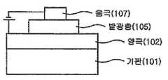
도 1에는 기판(101) 위에 양극(102), 발광층(105) 및 음극(107)이 순차적으로 적층된 유기 발광 소자의 구조가 예시되어 있다. 이와 같은 구조에 있어서, 상기 화학식 1의 화합물은 상기 발광층(105)에 포함될 수 있다.1 illustrates a structure of an organic light emitting device in which an anode 102, a light emitting layer 105, and a cathode 107 are sequentially stacked on a substrate 101. In such a structure, the compound of Formula 1 may be included in the light emitting layer 105.
도 2에는 기판(101) 위에 양극(102), 정공 주입/정공 수송 및 발광층(105), 전자 수송층(106) 및 음극(107)이 순차적으로 적층된 유기 발광 소자의 구조가 예시되어 있다. 이와 같은 구조에 있어서, 상기 화학식 1의 화합물은 정공 주입/정공 수송 및 발광층(105)에 포함될 수 있다.2 illustrates a structure of an organic light emitting device in which an anode 102, a hole injection / hole transport and light emitting layer 105, an electron transport layer 106, and a cathode 107 are sequentially stacked on a substrate 101. In such a structure, the compound of Formula 1 may be included in the hole injection / hole transport and the light emitting layer 105.
도 3에는 기판(101), 양극(102), 정공 주입층(103), 정공 수송 및 발광층(105), 전자 수송층(106) 및 음극(107)이 순차적으로 적층된 유기 발광 소자의 구조가 예시되어 있다. 이와 같은 구조에 있어서, 상기 화학식 1의 화합물은 정공 주입/정공 수송 및 발광층(105)에 포함될 수 있다.3 illustrates a structure of an organic light emitting device in which a substrate 101, an anode 102, a hole injection layer 103, a hole transport and emission layer 105, an electron transport layer 106, and a cathode 107 are sequentially stacked. It is. In such a structure, the compound of Formula 1 may be included in the hole injection / hole transport and the light emitting layer 105.
도 4에는 기판(101), 양극(102), 정공 주입층(103), 정공 수송층(104), 전자 수송 및 발광층(105) 및 음극(107)이 순차적으로 적층된 유기 발광 소자의 구조가 예시되어 있다. 이와 같은 구조에 있어서, 상기 화학식 1의 화합물은 전자 수송 및 발광층(105)에 포함될 수 있다.4 illustrates a structure of an organic light emitting device in which a substrate 101, an anode 102, a hole injection layer 103, a hole transport layer 104, an electron transport and light emitting layer 105, and a cathode 107 are sequentially stacked. It is. In such a structure, the compound of Formula 1 may be included in the electron transport and emission layer 105.
예컨대, 본 발명에 따른 유기 발광 소자는 스퍼터링(sputtering)이나 전자빔 증발(e-beam evaporation)과 같은 PVD(physical vapor deposition) 방법을 이용하여, 기판 상에 금속 또는 전도성을 가지는 금속 산화물 또는 이들의 합금을 증착시켜 양극을 형성하고, 그 위에 정공 주입층, 정공 수송층, 발광층 및 전자 수송층을 포함하는 유기물층을 형성한 후, 그 위에 음극으로 사용할 수 있는 물질을 증착시킴으로써 제조될 수 있다. 이와 같은 방법 외에도, 기판 상에 음극 물질부터 유기물층, 양극 물질을 차례로 증착시켜 유기 발광 소자를 만들 수도 있다.For example, the organic light emitting device according to the present invention uses a metal vapor deposition (PVD) method such as sputtering or e-beam evaporation, and has a metal oxide or a metal oxide or an alloy thereof on a substrate. It can be prepared by depositing an anode to form an anode, an organic material layer including a hole injection layer, a hole transport layer, a light emitting layer and an electron transport layer thereon, and then depositing a material that can be used as a cathode thereon. In addition to the above method, an organic light emitting device may be manufactured by sequentially depositing a cathode material, an organic material layer, and an anode material on a substrate.
상기 유기물층은 정공 주입층, 정공 수송층, 발광층 및 전자 수송층 등을 포함하는 다층 구조일 수도 있으나, 이에 한정되지 않고 단층 구조일 수 있다. 또한, 상기 유기물층은 다양한 고분자 소재를 사용하여 증착법이 아닌 용매 공정(solvent process), 예컨대 스핀 코팅, 딥 코팅, 닥터 블레이딩, 스크린 프린팅, 잉크젯 프린팅 또는 열 전사법 등의 방법에 의하여 더 적은 수의 층으로 제조할 수 있다.The organic material layer may have a multilayer structure including a hole injection layer, a hole transport layer, a light emitting layer, and an electron transport layer, but is not limited thereto and may have a single layer structure. In addition, the organic material layer may be formed by using a variety of polymer materials, and by using a method such as spin coating, dip coating, doctor blading, screen printing, inkjet printing, or thermal transfer method, rather than a deposition method. It can be prepared in layers.
상기 양극 물질로는 통상 유기물층으로 정공 주입이 원활할 수 있도록 일함수가 큰 물질이 바람직하다. 본 발명에서 사용될 수 있는 양극 물질의 구체적인 예로는 바나듐, 크롬, 구리, 아연, 금과 같은 금속 또는 이들의 합금; 아연 산화물, 인듐 산화물, 인듐주석 산화물(ITO), 인듐아연 산화물(IZO)과 같은 금속 산화물; ZnO : Al 또는 SnO2 : Sb와 같은 금속과 산화물의 조합; 폴리(3-메틸화합물의), 폴리[3,4-(에틸렌-1,2-디옥시)화합물의](PEDT), 폴리피롤 및 폴리아닐린과 같은 전도 성 고분자 등이 있으나, 이들에만 한정되는 것은 아니다.As the anode material, a material having a large work function is usually preferred to facilitate hole injection into the organic material layer. Specific examples of the positive electrode material that can be used in the present invention include metals such as vanadium, chromium, copper, zinc and gold or alloys thereof; Metal oxides such as zinc oxide, indium oxide, indium tin oxide (ITO), indium zinc oxide (IZO); A combination of a metal and an oxide such as ZnO: Al or SnO2 : Sb; Conductive polymers such as poly (3-methyl compound), poly [3,4- (ethylene-1,2-dioxy)] (PEDT), polypyrrole and polyaniline, but are not limited thereto. .
상기 음극 물질로는 통상 유기물층으로 전자 주입이 용이하도록 일함수가 작은 물질인 것이 바람직하다. 음극 물질의 구체적인 예로는 마그네슘, 칼슘, 나트륨, 칼륨, 티타늄, 인듐, 이트륨, 리튬, 가돌리늄, 알루미늄, 은, 주석 및 납과 같은 금속 또는 이들의 합금; LiF/Al 또는 LiO2/Al과 같은 다층 구조 물질 등이 있으나, 이들에만 한정되는 것은 아니다.It is preferable that the cathode material is a material having a small work function to facilitate electron injection into the organic material layer. Specific examples of the negative electrode material include metals such as magnesium, calcium, sodium, potassium, titanium, indium, yttrium, lithium, gadolinium, aluminum, silver, tin, and lead or alloys thereof; Multilayer structure materials such as LiF / Al or LiO2 / Al, and the like, but are not limited thereto.
상기 정공 주입 물질로는 낮은 전압에서 양극으로부터 정공을 잘 주입받을 수 있는 물질로서, 정공 주입 물질의 HOMO(highest occupied molecular orbital)가 양극 물질의 일함수와 주변 유기물층의 HOMO 사이인 것이 바람직하다. 정공 주입 물질의 구체적인 예로는 금속 포피린(porphyrine), 올리고티오펜, 아릴아민 계열의 유기물, 헥사니트릴헥사아자트리페닐렌 계열의 유기물, 퀴나크리돈(quinacridone) 계열의 유기물, 페릴렌(perylene) 계열의 유기물, 안트라퀴논 및 폴리아닐린과 폴리티오펜 계열의 전도성 고분자 등이 있으나, 이들에만 한정되는 것은 아니다.The hole injection material is a material capable of well injecting holes from the anode at a low voltage, and the highest occupied molecular orbital (HOMO) of the hole injection material is preferably between the work function of the anode material and the HOMO of the surrounding organic material layer. Specific examples of the hole injection material include metal porphyrine, oligothiophene, arylamine-based organics, hexanitrile hexaazatriphenylene-based organics, quinacridone-based organics, and perylene-based Organic substances, anthraquinone and polyaniline and polythiophene-based conductive polymers, but are not limited thereto.
상기 정공 수송 물질로는 양극이나 정공 주입층으로부터 정공을 수송받아 발광층으로 옮겨줄 수 있는 물질로 정공에 대한 이동성이 큰 물질이 적합하다. 구체적인 예로는 아릴아민 계열의 유기물, 전도성 고분자, 및 공액 부분과 비공액 부분이 함께 있는 블록 공중합체 등이 있으나, 이들에만 한정되는 것은 아니다.As the hole transporting material, a material capable of transporting holes from the anode or the hole injection layer to be transferred to the light emitting layer is suitable. Specific examples thereof include an arylamine-based organic material, a conductive polymer, and a block copolymer having a conjugated portion and a non-conjugated portion together, but are not limited thereto.
상기 발광 물질로는 정공 수송층과 전자 수송층으로부터 정공과 전자를 각각 수송받아 결합시킴으로써 가시광선 영역의 빛을 낼 수 있는 물질로서, 형광이나 인 광에 대한 양자 효율이 좋은 물질이 바람직하다. 구체적인 예로는 8-히드록시-퀴놀린 알루미늄 착물(Alq3); 카르바졸 계열 화합물; 이량체화 스티릴(dimerized styryl) 화합물; BAlq; 10-히드록시벤조 퀴놀린-금속 화합물; 벤족사졸, 벤즈티아졸 및 벤즈이미다졸 계열의 화합물; 폴리(p-페닐렌비닐렌)(PPV) 계열의 고분자; 스피로(spiro) 화합물; 폴리플루오렌, 루브렌 등이 있으나, 이들에만 한정되는 것은 아니다.The light emitting material is a material capable of emitting light in the visible region by transporting and combining holes and electrons from the hole transport layer and the electron transport layer, respectively, and a material having good quantum efficiency with respect to fluorescence or phosphorus light is preferable. Specific examples thereof include 8-hydroxyquinoline aluminum complex (Alq3 ); Carbazole series compounds; Dimerized styryl compounds; BAlq; 10-hydroxybenzoquinoline-metal compound; Benzoxazole, benzthiazole and benzimidazole series compounds; Poly (p-phenylenevinylene) (PPV) -based polymers; Spiro compounds; Polyfluorene, rubrene and the like, but are not limited thereto.
상기 전자 수송 물질로는 음극으로부터 전자를 잘 주입 받아 발광층으로 옮겨줄 수 있는 물질로서, 전자에 대한 이동성이 큰 물질이 적합하다. 구체적인 예로는 8-히드록시퀴놀린의 Al 착물; Alq3를 포함한 착물; 유기 라디칼 화합물; 히드록시플라본-금속 착물 등이 있으나, 이들에만 한정되는 것은 아니다.The electron transporting material is a material capable of injecting electrons well from the cathode and transferring the electrons to the light emitting layer. A material having high mobility to electrons is suitable. Specific examples include Al complexes of 8-hydroxyquinoline; Complexes including Alq3 ; Organic radical compounds; Hydroxyflavone-metal complexes, and the like, but are not limited thereto.
본 발명에 따른 유기 발광 소자는 사용되는 재료에 따라 전면 발광형, 후면 발광형 또는 양면 발광형일 수 있다.The organic light emitting device according to the present invention may be a top emission type, a bottom emission type or a double-sided emission type depending on the material used.
본 발명에 따른 화합물은 유기 태양 전지, 유기 감광체, 유기 트랜지스터 등을 비롯한 유기 전자 소자에서도 유기 발광 소자에 적용되는 것과 유사한 원리로 작용할 수 있다.The compound according to the present invention may also operate on a principle similar to that applied to organic light emitting devices in organic electronic devices including organic solar cells, organic photoconductors, organic transistors, and the like.
따라서, 상기 유기 전자 소자는 유기 발광 소자, 유기 인광 소자, 유기 태양 전지, 유기 감광체(OPC) 및 유기 트랜지스터로 이루어진 군에서 선택될 수 있다.Therefore, the organic electronic device may be selected from the group consisting of an organic light emitting device, an organic phosphorescent device, an organic solar cell, an organic photoconductor (OPC), and an organic transistor.
이하, 실시예를 통하여 본 발명의 화학식 1로 표시되는 화합물들의 제조방법 및 이들을 이용한 유기 전자 소자의 제조방법 및 성능에 대하여 구체적으로 설명한 다. 그러나, 하기 실시예는 설명을 위한 것이며, 본 발명의 범위가 하기 실시예에 의하여 한정되는 것은 아니다.Hereinafter, the method of preparing the compounds represented by Chemical Formula 1 of the present invention and the method and performance of the organic electronic device using the same will be described in detail through Examples. However, the following examples are for illustrative purposes, and the scope of the present invention is not limited by the following examples.
실시예에 있어서 평가 방법은 하기와 같다.In the Example, the evaluation method is as follows.
1. 구동전압: Kethley 236(source measure unit)을 사용하여 측정Drive voltage: measured using Kethley 236 (source measure unit)
2. 전류효율: SpectraScan Pr-650을 사용하여 측정2. Current efficiency: measured using SpectraScan Pr-650
3. 색좌표: SpectraScan Pr-650을 사용하여 측정3. Color coordinates: measured using SpectraScan Pr-650
본 발명에 따른 화학식 1로 표시되는 화합물은 일반적으로 다단계 화학 반응으로 제조될 수 있다. 즉, 일부 중간체 화합물이 먼저 제조되고, 그 중간체 화합물들로부터 화학식 1의 화합물이 제조된다. 예증적인 중간체 화합물들은 하기 표에 실려 있는 화합물들이다.The compound represented by Formula 1 according to the present invention may generally be prepared by a multistage chemical reaction. That is, some intermediate compounds are prepared first, and compounds of formula 1 are prepared from the intermediate compounds. Exemplary intermediate compounds are the compounds listed in the table below.
이하, 본 발명의 이해를 돕기 위하여 바람직한 실시예를 제시한다. 그러나, 하기의 실시예는 본 발명을 예시하기 위한 것이며, 이에 의하여 본 발명의 범위가 한정되는 것은 아니다.Hereinafter, preferred embodiments of the present invention will be described in order to facilitate understanding of the present invention. However, the following examples are intended to illustrate the invention, whereby the scope of the invention is not limited.
<<실시예Example>>
<<합성예Synthetic example 1> 1>

1) 화합물 1A의 제조1) Preparation of Compound 1A
2-(4,4,5,5-테트라메틸-1,3,2-디옥사보로란-2-일)벤조[h]퀴놀린(2-(4,4,5,5-tetramethyl-1,3,2-dioxaborolan-2-yl)benzo[h]quinoline, 30.5g, 100mmol), 1-브로모-2-요오도벤젠(28.3g, 100mmol)를 테트라하이드로퓨란(400mL)에 완전히 녹인 후, 2M 탄산칼륨 수용액을 첨가하고, 테트라비스트리페닐포스피노 팔라듐(2.3g, 2mmol)을 넣은 후, 10시간 동안 가열 교반하였다. 상온으로 온도를 낮추고, 생성된 용액을 무수 황산마그네슘으로 건조하고, CHCl3/n-Hex으로 재결정하여 상기 화합물 1A인 2-(2-브로모페닐)벤조[h]퀴놀린(2-(2-bromophenyl)benzo[h]quinoline, 24.1g, 수율 72%)을 제조하였다.2- (4,4,5,5-tetramethyl-1,3,2-dioxaborolan-2-yl) benzo [h] quinoline (2- (4,4,5,5-tetramethyl-1 , 3,2-dioxaborolan-2-yl) benzo [h] quinoline, 30.5g, 100mmol), 1-bromo-2-iodobenzene (28.3g, 100mmol) dissolved in tetrahydrofuran (400mL) completely , 2M potassium carbonate aqueous solution was added, tetrabistriphenylphosphino palladium (2.3 g, 2 mmol) was added thereto, and the mixture was heated and stirred for 10 hours. The temperature was lowered to room temperature, the resulting solution was dried over anhydrous magnesium sulfate, recrystallized with CHCl3 / n-Hex, and the compound 1A 2- (2-bromophenyl) benzo [h] quinoline (2- (2- bromophenyl) benzo [h] quinoline, 24.1 g, yield 72%) was prepared.
MS : [M+H]+= 334MS: [M + H]+ = 334
2) 화합물 1B의 제조2) Preparation of Compound 1B
상기 1)에서 합성한 화합물 1A(24.1g, 72.1mmol)를 질소 분위기하에서 무수 THF(100mL)를 넣고, -78oC로 반응 온도를 유지하였다. n-BuLi(2.5M in HEX, 34.6mL, 87mmol)을 반응 용액에 적가하였다. 약 40분 동안 교반한 후 반응 혼합 용액에 2,7-디브로모플루오레논(2,7-dibromofluorenone, 24.7g, 35mmol)을 가해 교반하였다. 약 1시간 후 상온으로 승온한 후 3시간 동안 교반하였다. 반응 혼합물에 수용성 염화암모늄 용액을 가한 후 THF층을 분리하였다. 무수 황산 마그네슘으로 유기층을 건조시킨 후, 에틸에테르를 가해 고체 화합물을 제조하였다.Compound 1A (24.1 g, 72.1 mmol) synthesized in 1) above was added with anhydrous THF (100 mL) under a nitrogen atmosphere, and the reaction temperature was maintained at −78° C. n-BuLi (2.5M in HEX, 34.6 mL, 87 mmol) was added dropwise to the reaction solution. After stirring for about 40 minutes, 2,7-dibromofluorenone (2,7-dibromofluorenone, 24.7 g, 35 mmol) was added to the reaction mixture and stirred. After about 1 hour to warm up to room temperature and stirred for 3 hours. Aqueous ammonium chloride solution was added to the reaction mixture, and the THF layer was separated. The organic layer was dried over anhydrous magnesium sulfate, and then ethyl ether was added to prepare a solid compound.
3) 화합물 1C의 제조3) Preparation of Compound 1C
상기 2)에서 얻은 화합물 1B를 더 이상 정제하지 않고, 아세트산 100mL를 가해 교반하였다. 반응 용액에 황산 2mL을 적가한 후 80도에서 가열 교반하였다. 8시간 동안 교반 후 상온으로 식혀 생성된 노란색 고체를 여과하고, 물과 에탄올로 씻은 후 건조하였다. 건조된 화합물을 1M NaOH 용액 200mL를 가해 교반한 후 물로 씻어준 후 여과하여 화합물 1C(39g, 수율 94%)를 제조하였다.The compound 1B obtained in the above 2) was no longer purified, but 100 mL of acetic acid was added and stirred. 2 mL of sulfuric acid was added dropwise to the reaction solution, followed by heating and stirring at 80 ° C. After stirring for 8 hours, the resulting yellow solid was cooled to room temperature, filtered, washed with water and ethanol and dried. 200 mL of 1 M NaOH solution was added to the dried compound, which was then stirred and washed with water to obtain Compound 1C (39 g, yield 94%).
MS : [M+H]+= 575MS: [M + H]+ = 575
<<합성예Synthetic example 2> 2>

1) 화합물 2B의 제조1) Preparation of Compound 2B
상기 합성예 1의 1)에서 합성한 화합물 1A(12g, 36mmol)를 질소 분위기하에서 무수 THF(100mL)를 넣고, -78oC로 반응 온도를 유지하였다. n-BuLi(2.5M in HEX, 17.2mL, 43mmol)을 반응 용액에 적가하였다. 약 40분 동안 교반한 후 반응 혼합 용액에 2-브로모플루오레논(2-bromofluorenone, 9.1g, 35mmol)을 가해 교반하였다. 약 1시간 후 상온으로 승온한 후 3시간 동안 교반하였다. 반응 혼합물에 수용성 염화암모늄 용액을 가한 후 THF층을 분리하였다. 무수 황산 마그네슘으로 유기층을 건조시킨 후, 에틸에테르를 가해 고체 화합물 2B를 제조하였다.Compound 1A (12 g, 36 mmol) synthesized in 1) of Synthesis Example 1 was added with anhydrous THF (100 mL) under a nitrogen atmosphere, and the reaction temperature was maintained at -78° C. n-BuLi (2.5M in HEX, 17.2 mL, 43 mmol) was added dropwise to the reaction solution. After stirring for about 40 minutes, 2-bromofluorenone (2-bromofluorenone, 9.1 g, 35 mmol) was added to the reaction mixture and stirred. After about 1 hour to warm up to room temperature and stirred for 3 hours. Aqueous ammonium chloride solution was added to the reaction mixture, and the THF layer was separated. After drying the organic layer with anhydrous magnesium sulfate, ethyl ether was added to prepare a solid compound 2B.
2) 화합물 2C의 제조2) Preparation of Compound 2C
상기 1)에서 얻은 화합물 2B를 더 이상 정제하지 않고, 아세트산 100mL를 가해 교반하였다. 반응 용액에 황산 2mL을 적가한 후 80도에서 가열 교반하였다. 8시간 동안 교반 후 상온으로 식혀 생성된 노란색 고체를 여과하고, 건조된 화합물을 1M NaOH 용액 120mL를 가해 교반한 후 물로 씻어준 후 여과하여 화합물 2C(15.7g, 수율 88%)를 제조하였다.The compound 2B obtained in the above 1) was no longer purified, but 100 mL of acetic acid was added and stirred. 2 mL of sulfuric acid was added dropwise to the reaction solution, followed by heating and stirring at 80 ° C. After stirring for 8 hours, the yellow solid formed by cooling to room temperature was filtered, and the dried compound was stirred with 120 mL of 1M NaOH solution, washed with water, and filtered to prepare Compound 2C (15.7 g, yield 88%).
MS : [M+H]+= 496MS: [M + H]+ = 496
<<합성예Synthetic example 3> 3>

1) 화합물 3A의 제조1) Preparation of Compound 3A
2-(4,4,5,5-테트라메틸-1,3,2-디옥사보로란-2-일)퀴놀린(2-(4,4,5,5-tetramethyl-1,3,2-dioxaborolan-2-yl)quinoline, 26g, 100mmol), 1-브로모-2-요오도벤젠(28.3g, 100mmol)를 테트라하이드로퓨란(400mL)에 완전히 녹인 후, 2M 탄산칼륨 수용액을 첨가하고, 테트라비스트리페닐포스피노 팔라듐(2.3g, 2mmol)을 넣은 후, 10시간 동안 가열 교반하였다. 상온으로 온도를 낮추고, 생성된 용액을 무수 황산마그네슘으로 건조하고, CHCl3/n-Hex으로 재결정하여 상기 화학식 3A(22.2g, 수율 78%)를 제조하였다.2- (4,4,5,5-tetramethyl-1,3,2-dioxaborolan-2-yl) quinoline (2- (4,4,5,5-tetramethyl-1,3,2 -dioxaborolan-2-yl) quinoline, 26 g, 100 mmol) and 1-bromo-2-iodobenzene (28.3 g, 100 mmol) were completely dissolved in tetrahydrofuran (400 mL), and then 2M aqueous potassium carbonate solution was added thereto. Tetrabistriphenylphosphino palladium (2.3 g, 2 mmol) was added thereto, followed by heating and stirring for 10 hours. The temperature was lowered to room temperature, the resulting solution was dried over anhydrous magnesium sulfate, and recrystallized with CHCl3 / n-Hex to prepare Chemical Formula 3A (22.2 g, yield 78%).
MS : [M+H]+= 284MS: [M + H]+ = 284
2) 화합물 3B의 제조2) Preparation of Compound 3B
상기 1)에서 합성한 화합물 3A(10g, 35.2mmol)를 질소 분위기하에서 무수 THF(100mL)를 넣고, -78oC로 반응 온도를 유지하였다. n-BuLi(2.5M in HEX, 17.2mL, 43mmol)을 반응 용액에 적가하였다. 약 40분 동안 교반한 후 반응 혼합 용액에 2,7-디브로모플루오레논(2,7-dibromofluorenone, 9.1g, 35mmol)을 가해 교반하였다. 약 1시간 후 상온으로 승온한 후 3시간 동안 교반하였다. 반응 혼합물에 수용성 염화암모늄 용액을 가한 후 THF층을 분리하였다. 무수 황산 마그네슘으로 유기층을 건조시킨 후, 에틸에테르를 가해 고체 화합물을 제조하였다.Compound 3A (10 g, 35.2 mmol) synthesized in 1) above was put in anhydrous THF (100 mL) under a nitrogen atmosphere, and the reaction temperature was maintained at -78° C. n-BuLi (2.5M in HEX, 17.2 mL, 43 mmol) was added dropwise to the reaction solution. After stirring for about 40 minutes, 2,7-dibromofluorenone (2,7-dibromofluorenone, 9.1 g, 35 mmol) was added to the reaction mixture and stirred. After about 1 hour to warm up to room temperature and stirred for 3 hours. Aqueous ammonium chloride solution was added to the reaction mixture, and the THF layer was separated. The organic layer was dried over anhydrous magnesium sulfate, and then ethyl ether was added to prepare a solid compound.
3) 화합물 3C의 제조3) Preparation of Compound 3C
상기 2)에서 얻은 화합물 3B를 더 이상 정제하지 않고, 아세트산 100mL를 가해 교반하였다. 반응 용액에 황산 2mL을 적가한 후 80도에서 가열 교반하였다. 8시간 동안 교반 후 상온으로 식혀 생성된 노란색 고체를 여과하고, 물과 에탄올로 씻은 후 건조된 화합물을 1M NaOH 용액 120mL를 가해 교반한 후 물로 씻어준 후 여과하여 화합물 3C(9.9g, 수율 63%)를 제조하였다.The compound 3B obtained in the above 2) was no longer purified, but 100 mL of acetic acid was added and stirred. 2 mL of sulfuric acid was added dropwise to the reaction solution, followed by heating and stirring at 80 ° C. After stirring for 8 hours, the yellow solid formed by cooling to room temperature was filtered, washed with water and ethanol, and the dried compound was added with 120 mL of 1M NaOH solution, stirred, washed with water, and filtered to give compound 3C (9.9 g, 63% yield). ) Was prepared.
MS : [M+H]+= 446MS: [M + H]+ = 446
<<합성예Synthetic example 4> 4>

1) 화합물 4A의 제조1) Preparation of Compound 4A
5-(4,4,5,5-테트라메틸-1,3,2-디옥사보로란-2-일)퀴놀린(5-(4,4,5,5-tetramethyl-1,3,2-dioxaborolan-2-yl)quinoline, 28.4g, 100mmol), 1-브로모-2-요오도벤젠(28.3g, 100mmol)를 테트라하이드로퓨란(400mL)에 완전히 녹인 후, 2M 탄산칼륨 수용액을 첨가하고, 테트라비스트리페닐포스피노 팔라듐(2.3g, 2mmol)을 넣은 후, 10시간 동안 가열 교반하였다. 상온으로 온도를 낮추고, 생성된 용액을 무수 황산마그네슘으로 건조하고, CHCl3/n-Hex으로 컬럼정제하여 상기 화합물 4A(15.3g, 수율 54%)를 제조하였다.5- (4,4,5,5-tetramethyl-1,3,2-dioxaborolan-2-yl) quinoline (5- (4,4,5,5-tetramethyl-1,3,2 -dioxaborolan-2-yl) quinoline, 28.4g, 100mmol), 1-bromo-2-iodobenzene (28.3g, 100mmol) is completely dissolved in tetrahydrofuran (400mL), and then 2M aqueous potassium carbonate solution is added. Tetrabistriphenylphosphino palladium (2.3 g, 2 mmol) was added thereto, followed by heating and stirring for 10 hours. The temperature was lowered to room temperature, the resulting solution was dried over anhydrous magnesium sulfate, and column purified with CHCl3 / n-Hex to prepare Compound 4A (15.3 g, yield 54%).
MS : [M+H]+= 284MS: [M + H]+ = 284
2) 화합물 4B의 제조2) Preparation of Compound 4B
상기 1)에서 합성한 화합물 4A(15.3g, 54mmol)를 질소 분위기하에서 무수 THF(100mL)를 넣고, -78oC로 반응 온도를 유지하였다. n-BuLi(2.5M in HEX, 26mL, 65mmol)을 반응 용액에 적가하였다. 약 40분 동안 교반한 후 반응 혼합 용액에 2-브로모플루오레논(2-bromofluorenone, 14.0g, 35mmol)을 가해 교반하였다. 약 1시간 후 상온으로 승온한 후 3시간 동안 교반하였다. 반응 혼합물에 수용성 염화암모늄 용액을 가한 후 THF층을 분리하였다. 무수 황산 마그네슘으로 유기층을 건조시킨 후, 에틸에테르를 가해 고체 화합물 4B를 제조하였다.Compound 4A (15.3 g, 54 mmol) synthesized in 1) above was put in anhydrous THF (100 mL) under a nitrogen atmosphere, and the reaction temperature was maintained at -78° C. n-BuLi (2.5 M in HEX, 26 mL, 65 mmol) was added dropwise to the reaction solution. After stirring for about 40 minutes, 2-bromofluorenone (2-bromofluorenone, 14.0 g, 35 mmol) was added to the reaction mixture and stirred. After about 1 hour to warm up to room temperature and stirred for 3 hours. Aqueous ammonium chloride solution was added to the reaction mixture, and the THF layer was separated. After drying the organic layer with anhydrous magnesium sulfate, ethyl ether was added to prepare a solid compound 4B.
3) 화합물 4C의 제조3) Preparation of Compound 4C
상기 2)에서 얻은 화합물 4B를 더 이상 정제하지 않고, 아세트산 100mL를 가해 교반하였다. 반응 용액에 황산 2mL을 적가한 후 80도에서 가열 교반하였다. 8시 간 동안 교반 후 상온으로 식혀 생성된 노란색 고체를 여과하고, 물과 에탄올로 씻은 후 건조된 화합물을 1M NaOH 용액 200mL를 가해 교반한 후 물로 씻어준 후 여과하여 화합물 4C(24.7g, 수율 87%)를 제조하였다.The compound 4B obtained in the above 2) was no longer purified, and 100 mL of acetic acid was added thereto and stirred. 2 mL of sulfuric acid was added dropwise to the reaction solution, followed by heating and stirring at 80 ° C. After stirring for 8 hours, the yellow solid formed by cooling to room temperature was filtered, washed with water and ethanol, and the dried compound was stirred with 200 mL of a 1M NaOH solution, washed with water, and then filtered. Compound 4C (24.7 g, yield 87) %) Was prepared.
MS : [M+H]+= 525MS: [M + H]+ = 525
<<합성예Synthetic example 5> 5>

1) 화합물 5A의 제조1) Preparation of Compound 5A
6-(4,4,5,5-테트라메틸-1,3,2-디옥사보로란-2-일)페난트리딘(6-(4,4,5,5-tetramethyl-1,3,2-dioxaborolan-2-yl)phenanthridine, 31g, 100mmol), 1-브로모-2-요오도벤젠(28.3g, 100mmol)를 테트라하이드로퓨란(400mL)에 완전히 녹인 후, 2M 탄산칼륨 수용액을 첨가하고, 테트라비스트리페닐포스피노 팔라듐(2.3g, 2mmol)을 넣은 후, 10시간 동안 가열 교반하였다. 상온으로 온도를 낮추고, 생성된 용액을 무수 황산마그네슘으로 건조하고, CHCl3/n-Hex으로 컬럼정제하여 상기 화합물 5A(28.4g, 수율 85%)를 제조하였다.6- (4,4,5,5-tetramethyl-1,3,2-dioxaborolan-2-yl) phenanthridine (6- (4,4,5,5-tetramethyl-1,3 , 2-dioxaborolan-2-yl) phenanthridine, 31g, 100mmol) and 1-bromo-2-iodobenzene (28.3g, 100mmol) are completely dissolved in tetrahydrofuran (400mL), and then 2M aqueous potassium carbonate solution is added. Tetrabistriphenylphosphino palladium (2.3 g, 2 mmol) was added thereto, followed by heating and stirring for 10 hours. The temperature was lowered to room temperature, the resulting solution was dried over anhydrous magnesium sulfate, and column purified with CHCl3 / n-Hex to prepare compound 5A (28.4 g, yield 85%).
MS : [M+H]+= 334MS: [M + H]+ = 334
2) 화합물 5B의 제조2) Preparation of Compound 5B
상기 1)에서 합성한 화합물 5A(16.7g, 50mmol)를 질소 분위기하에서 무수 THF(100mL)를 넣고, -78oC로 반응 온도를 유지하였다. n-BuLi(2.5M in HEX, 24mL, 60mmol)을 반응 용액에 적가하였다. 약 40분 동안 교반한 후 반응 혼합 용액에 2-브로모플루오레논(2-bromofluorenone, 13g, 50mmol)을 가해 교반하였다. 약 1시간 후 상온으로 승온한 후 3시간 동안 교반하였다. 반응 혼합물에 수용성 염화암모늄 용액을 가한 후 THF층을 분리하였다. 무수 황산 마그네슘으로 유기층을 건조시킨 후, 에틸에테르를 가해 고체 화합물 5B를 제조하였다.Compound 5A (16.7 g, 50 mmol) synthesized in 1) above was put in anhydrous THF (100 mL) under a nitrogen atmosphere, and the reaction temperature was maintained at -78° C. n-BuLi (2.5 M in HEX, 24 mL, 60 mmol) was added dropwise to the reaction solution. After stirring for about 40 minutes, 2-bromofluorenone (2-bromofluorenone, 13 g, 50 mmol) was added to the reaction mixture and stirred. After about 1 hour to warm up to room temperature and stirred for 3 hours. Aqueous ammonium chloride solution was added to the reaction mixture, and the THF layer was separated. After drying the organic layer with anhydrous magnesium sulfate, ethyl ether was added to prepare a solid compound 5B.
3) 화합물 5C의 제조3) Preparation of Compound 5C
상기 2)에서 얻은 화합물 5B를 더 이상 정제하지 않고, 아세트산 100mL를 가해 교반하였다. 반응 용액에 황산 2mL을 적가한 후 80도에서 가열 교반하였다. 8시간 동안 교반 후 상온으로 식혀 생성된 노란색 고체를 여과하고, 물과 에탄올로 씻은 후 건조된 화합물을 1M NaOH 용액 200mL를 가해 교반한 후 물로 씻어준 후 여과하여 화합물 5C(17.9g, 수율 72%)를 제조하였다.The compound 5B obtained in the above 2) was no longer purified, but 100 mL of acetic acid was added and stirred. 2 mL of sulfuric acid was added dropwise to the reaction solution, followed by heating and stirring at 80 ° C. After stirring for 8 hours, the yellow solid formed by cooling to room temperature was filtered, washed with water and ethanol, and the dried compound was added with 200 mL of 1M NaOH solution, stirred, washed with water, and then filtered. Compound 5C (17.9 g, 72% yield) ) Was prepared.
MS : [M+H]+= 496MS: [M + H]+ = 496
<<합성예Synthetic example 6> 6>

1) 화합물 6A의 제조1) Preparation of Compound 6A
9-페닐-9H-카바졸-3-일-3-보론산(9-phenyl-9H-carbazol-3-yl-3-boronic acid, 19.9g, 50mmol), 1-브로모-2-요오도벤젠(14.2g, 50mmol)를 테트라하이드로퓨란(400mL)에 완전히 녹인 후, 2M 탄산칼륨 수용액을 첨가하고, 테트라비스트리페닐포스피노 팔라듐(2.3g, 2mmol)을 넣은 후, 10시간 동안 가열 교반하였다. 상온으로 온도를 낮추고, 생성된 용액을 무수 황산마그네슘으로 건조하고, CHCl3/n-Hex으로 컬럼정제하여 상기 화합물 6A(10.3g, 수율 52%)를 제조하였다.9-phenyl-9H-carbazol-3-yl-3-boronic acid (9-phenyl-9H-carbazol-3-yl-3-boronic acid, 19.9 g, 50 mmol), 1-bromo-2-iodo After benzene (14.2 g, 50 mmol) was completely dissolved in tetrahydrofuran (400 mL), 2M aqueous potassium carbonate solution was added, tetrabistriphenylphosphino palladium (2.3 g, 2 mmol) was added thereto, and the mixture was heated and stirred for 10 hours. . The temperature was lowered to room temperature, the resulting solution was dried over anhydrous magnesium sulfate, and column purified with CHCl3 / n-Hex to prepare Compound 6A (10.3 g, yield 52%).
MS : [M+H]+= 398MS: [M + H]+ = 398
2) 화합물 6B의 제조2) Preparation of Compound 6B
상기 1)에서 합성한 화합물 6A(10.3g, 25.9mmol)를 질소 분위기하에서 무수 THF(60mL)를 넣고, -78oC로 반응 온도를 유지하였다. n-BuLi(2.5M in HEX, 14.5mL, 36.3mmol)을 반응 용액에 적가하였다. 약 40분 동안 교반한 후 반응 혼합 용액에 2-브로모플루오레논(2-bromofluorenone, 6.5g, 25mmol)을 가해 교반하였다. 약 1시간 후 상온으로 승온한 후 3시간 동안 교반하였다. 반응 혼합물에 수용성 염화암모늄 용액을 가한 후 THF층을 분리하였다. 무수 황산 마그네슘으로 유기층을 건조시킨 후, 에틸에테르를 가해 고체 화합물 6B를 제조하였다.Compound 6A (10.3 g, 25.9 mmol) synthesized in 1) above was added with anhydrous THF (60 mL) under a nitrogen atmosphere, and the reaction temperature was maintained at -78° C. n-BuLi (2.5 M in HEX, 14.5 mL, 36.3 mmol) was added dropwise to the reaction solution. After stirring for about 40 minutes, 2-bromofluorenone (2-bromofluorenone, 6.5 g, 25 mmol) was added to the reaction mixture and stirred. After about 1 hour to warm up to room temperature and stirred for 3 hours. Aqueous ammonium chloride solution was added to the reaction mixture, and the THF layer was separated. After drying the organic layer with anhydrous magnesium sulfate, ethyl ether was added to prepare a solid compound 6B.
3) 화합물 6C의 제조3) Preparation of Compound 6C
상기 2)에서 얻은 화합물 6B를 더 이상 정제하지 않고, 아세트산 60mL를 가해 교반하였다. 반응 용액에 황산 1mL을 적가한 후 60도에서 가열 교반하였다. 5시간 동안 교반 후 상온으로 식혀 생성된 노란색 고체를 여과하고, 물과 에탄올로 씻은 후 건조된 화합물을 1M NaOH 용액 100mL를 가해 교반한 후 물로 씻어준 후 여과하여 화합물 6C(6.2g, 수율 44%)를 제조하였다.The compound 6B obtained in the above 2) was no longer purified, but 60 mL of acetic acid was added thereto and stirred. 1 mL of sulfuric acid was added dropwise to the reaction solution, followed by heating and stirring at 60 ° C. After stirring for 5 hours, the yellow solid formed by cooling to room temperature was filtered, washed with water and ethanol, and the dried compound was stirred by adding 100 mL of 1M NaOH solution, washed with water, and then filtered. Compound 6C (6.2 g, yield 44% ) Was prepared.
MS : [M+H]+= 560MS: [M + H]+ = 560
<<제조예Production Example 1> 화합물 1-1-25의 제조 1> Preparation of Compound 1-1-25

2-(4,4,5,5-테트라메틸-1.3,2-디옥사보로란-2-일)벤조[h]퀴놀린(2-(4,4,5,5-tetramethyl-1,3,2-dioxaborolan-2-yl)benzo[h]quinoline, 13.4g, 44.0mmol), 화합 물 1C(6.7g, 20.0mmol) 및 탄산나트륨(5.5g, 40.0mmol)을 테트라히드로퓨란(300mL) 및 물(100mL)의 혼합물 내 현탁시켰다. 테트라키스(트리페닐포스핀)팔라듐(0.4g, 0.36mmol)을 상기 현탁액에 가하였다. 혼합물을 환류에서 약 24시간 동안 교반한 다음 실온으로 냉각하였다. 생성된 고체를 여과한 THF/EtOH로 정제하여 화합물 1-1-25(7.1g, 수율 46%)를 제조하였다.2- (4,4,5,5-tetramethyl-1.3,2-dioxaborolan-2-yl) benzo [h] quinoline (2- (4,4,5,5-tetramethyl-1,3 , 2-dioxaborolan-2-yl) benzo [h] quinoline, 13.4 g, 44.0 mmol), compound 1C (6.7 g, 20.0 mmol) and sodium carbonate (5.5 g, 40.0 mmol) were added to tetrahydrofuran (300 mL) and water. (100 mL) was suspended in a mixture. Tetrakis (triphenylphosphine) palladium (0.4 g, 0.36 mmol) was added to the suspension. The mixture was stirred at reflux for about 24 hours and then cooled to room temperature. The resulting solid was purified by filtered THF / EtOH to give compound 1-1-25 (7.1 g, yield 46%).
MS [M+H]+ = 772MS [M + H]+ = 772
<<제조예Production Example 2> 화합물 1-1-23의 제조 2> Preparation of Compound 1-1-23

나프탈렌-2-일-2-보론산(naphthalen-2-yl-2-boronic acid, 7.6g, 44mmol), 화합물 1C(7.0g, 21mmol) 및 탄산나트륨(5.0g, 35.9mmol)을 테트라히드로퓨란(300mL) 및 물(100mL)의 혼합물 내 현탁시켰다. 테트라키스(트리페닐포스핀)팔라듐(0.4g, 0.36mmol)을 상기 현탁액에 가하였다. 혼합물을 환류에서 약 24시간 동안 교반한 다음 실온으로 냉각하였다. 생성된 고체를 여과한 THF/EtOH로 정제하여 화합물 1-1-23(10.7g, 수율 76%)를 제조하였다.Naphthalen-2-yl-2-boronic acid (7.6 g, 44 mmol), compound 1C (7.0 g, 21 mmol) and sodium carbonate (5.0 g, 35.9 mmol) were added to tetrahydrofuran ( 300 mL) and water (100 mL). Tetrakis (triphenylphosphine) palladium (0.4 g, 0.36 mmol) was added to the suspension. The mixture was stirred at reflux for about 24 hours and then cooled to room temperature. The resulting solid was purified by filtered THF / EtOH to give compound 1-1-23 (10.7 g, 76% yield).
MS [M+H]+ = 670MS [M + H]+ = 670
<<제조예Production Example 3> 화합물 1-1-17의 제조 3> Preparation of Compound 1-1-17

상기 제조예 1의 1-1-25의 제조예에 있어서, 2-(4,4,5,5-테트라메틸-1,3,2-디옥사보로란-2-일)벤조[h]퀴놀린(2-(4,4,5,5-tetramethyl-1,3,2-dioxaborolan-2-yl)benzo[h]quinoline) 대신에 2-(2-(4,4,5,5-테트라메틸-1,3,2-디옥사보로란-2-일)나프탈렌-6-일)-1-페닐-1H-벤조[d]이미다졸(2-(2-(4,4,5,5-tetramethyl-1,3,2-dioxaborolan-2-yl)naphthalen-6-yl)-1-phenyl-1H-benzo[d]imidazole, 4.5g, 10.0mmol)과 화합물 1C 대신에 화합물 2C(4.9g, 10mmol)를 사용한 것을 제외하고 동일한 방법으로 반응하여 화합물 1-1-17(4.8g, 수율 65%)을 제조하였다.In Preparation Example 1-1-25 of Preparation Example 1, 2- (4,4,5,5-tetramethyl-1,3,2-dioxaborolan-2-yl) benzo [h] 2- (2- (4,4,5,5-tetra) instead of quinoline (2- (4,4,5,5-tetramethyl-1,3,2-dioxaborolan-2-yl) benzo [h] quinoline) Methyl-1,3,2-dioxaborolan-2-yl) naphthalen-6-yl) -1-phenyl-1H-benzo [d] imidazole (2- (2- (4,4,5, 5-tetramethyl-1,3,2-dioxaborolan-2-yl) naphthalen-6-yl) -1-phenyl-1H-benzo [d] imidazole, 4.5 g, 10.0 mmol) and compound 2C (4.9) instead of compound 1C g, 10 mmol) was reacted in the same manner to prepare compound 1-1-17 (4.8 g, yield 65%).
MS [M+H]+ = 736MS [M + H]+ = 736
<<제조예Production Example 4> 화합물 1-1-19의 제조 4> Preparation of Compound 1-1-19

상기 제조예 1의 1-1-25의 제조예에 있어서, 2-(4,4,5,5-테트라메틸-1,3,2-디옥사보로란-2-일)벤조[h]퀴놀린(2-(4,4,5,5-tetramethyl-1,3,2-dioxaborolan-2-yl)benzo[h]quinoline) 대신에, 2-(4-(4,4,5,5-테트라메틸-1,3,2-디옥사보로란-2-일)페닐)-4,6-디페닐-1,3,5-트리아진(2-(4-(4,4,5,5-tetramethyl-1,3,2-dioxaborolan-2-yl)phenyl)-4,6-diphenyl-1,3,5-triazine, 4.4g, 10.0mmol)을 사용한 것을 제외하고 동일한 방법으로 반응하여 화합물 1-1-19(3.6g, 수율 49%)를 제조하였다.In Preparation Example 1-1-25 of Preparation Example 1, 2- (4,4,5,5-tetramethyl-1,3,2-dioxaborolan-2-yl) benzo [h] Instead of quinoline (2- (4,4,5,5-tetramethyl-1,3,2-dioxaborolan-2-yl) benzo [h] quinoline), 2- (4- (4,4,5,5- Tetramethyl-1,3,2-dioxaborolan-2-yl) phenyl) -4,6-diphenyl-1,3,5-triazine (2- (4- (4,4,5, 5-tetramethyl-1,3,2-dioxaborolan-2-yl) phenyl) -4,6-diphenyl-1,3,5-triazine, 4.4 g, 10.0 mmol), except that the compound was reacted in the same manner. 1-1-19 (3.6 g, 49% yield) was prepared.
MS [M+H]+ = 725MS [M + H]+ = 725
<<제조예Production Example 5> 화합물 1-5-1의 제조 5> Preparation of Compound 1-5-1

상기 제조예 1의 1-1-25의 제조예에 있어서, 2-[9,10-디-2-나프탈레닐-2-안트라세닐]-4,4,5,5-테트라메틸-1,3,2-디옥사보로란(2-[9,10-di-2-naphthalenyl-2-anthracenyl]-4,4,5,5-tetramethyl-1,3,2-dioxaborolane) 대신에 9-(나프탈렌-3-일)안트라센-10-일-10-보론산(9-(naphthalen-3-yl)anthracen-10-yl-10-boronic acid, 3.5g, 10.0mmol)을 사용한 것을 제외하고 동일한 방법으로 반응하여 화합물 1-5-1(4.1g, 수율 57%)을 제조하였다.In Preparation Example 1-1-25 of Preparation Example 1, 2- [9,10-di-2-naphthalenyl-2-anthracenyl] -4,4,5,5-tetramethyl-1, 9- instead of 3,2-dioxaborolane (2- [9,10-di-2-naphthalenyl-2-anthracenyl] -4,4,5,5-tetramethyl-1,3,2-dioxaborolane) The same except that (naphthalen-3-yl) anthracene-10-yl-10-boronic acid (9- (naphthalen-3-yl) anthracen-10-yl-10-boronic acid, 3.5 g, 10.0 mmol) was used. Reaction was performed to prepare compound 1-5-1 (4.1 g, yield 57%).
MS [M+H]+ = 719MS [M + H]+ = 719
<<제조예Production Example 6> 화합물 1-6-1의 제조 6> Preparation of Compound 1-6-1

상기 제조예 1의 1-1-25의 제조예에 있어서, 2-[9,10-디-2-나프탈레닐-2-안트라세닐]-4,4,5,5-테트라메틸-1,3,2-디옥사보로란(2-[9,10-di-2-naphthalenyl-2-anthracenyl]-4,4,5,5-tetramethyl-1,3,2-dioxaborolane) 대신에 2-(4-(4,4,5,5-테트라메틸-1,3,2-디옥사보로란-2-일)페닐)-1-페닐-1H-벤조[d]이미다졸(2-(4-(4,4,5,5-tetramethyl-1,3,2-dioxaborolan-2-yl)phenyl)-1-phenyl-1H- benzo[d]imidazole, 4.0g, 10.0mmol)을, 화합물 2C 대신에 화합물 3C(5.2g, 10.0mmol)를 사용한 것을 제외하고 동일한 방법으로 반응하여 화합물 1-6-1(3.9g, 수율 52%)을 제조하였다.In Preparation Example 1-1-25 of Preparation Example 1, 2- [9,10-di-2-naphthalenyl-2-anthracenyl] -4,4,5,5-tetramethyl-1, 2- instead of 3,2-dioxaborolane (2- [9,10-di-2-naphthalenyl-2-anthracenyl] -4,4,5,5-tetramethyl-1,3,2-dioxaborolane) (4- (4,4,5,5-tetramethyl-1,3,2-dioxaborolan-2-yl) phenyl) -1-phenyl-1H-benzo [d] imidazole (2- ( 4- (4,4,5,5-tetramethyl-1,3,2-dioxaborolan-2-yl) phenyl) -1-phenyl-1H-benzo [d] imidazole, 4.0 g, 10.0 mmol), compound 2C Instead of reacting in the same manner except using compound 3C (5.2g, 10.0mmol) Compound 1-6-1 (3.9g, 52% yield) was prepared.
MS [M+H]+ = 686MS [M + H]+ = 686
<<제조예Production Example 7> 화합물 1-6-7의 제조 7> Preparation of Compound 1-6-7

상기 제조예 1의 1-1-25의 제조예에 있어서, 2-[9,10-디-2-나프탈레닐-2-안트라세닐]-4,4,5,5-테트라메틸-1,3,2-디옥사보로란(2-[9,10-di-2-naphthalenyl-2-anthracenyl]-4,4,5,5-tetramethyl-1,3,2-dioxaborolane) 대신에 4,4,5,5-테트라메틸-2-(2-(나프탈렌-7-일)나프탈렌-6-일)-1,3,2-디옥사보로란(4,4,5,5-tetramethyl-2-(2-(naphthalen-7-yl)naphthalen-6-yl)-1,3,2-dioxaborolane, 4.0g, 10.5mmol)을 사용한 것을 제외하고 동일한 방법으로 반응하여 화합물 1-6-7(4.7g, 수율 58%)을 제조하였다.In Preparation Example 1-1-25 of Preparation Example 1, 2- [9,10-di-2-naphthalenyl-2-anthracenyl] -4,4,5,5-tetramethyl-1, 4, instead of 3,2-dioxaborolane (2- [9,10-di-2-naphthalenyl-2-anthracenyl] -4,4,5,5-tetramethyl-1,3,2-dioxaborolane) 4,5,5-tetramethyl-2- (2- (naphthalen-7-yl) naphthalen-6-yl) -1,3,2-dioxaborolan (4,4,5,5-tetramethyl- The reaction was carried out in the same manner, except that 2- (2- (naphthalen-7-yl) naphthalen-6-yl) -1,3,2-dioxaborolane, 4.0 g, 10.5 mmol) was used. 4.7 g, yield 58%) was prepared.
MS [M+H]+ = 670MS [M + H]+ = 670
<<제조예Production Example 8> 화합물 1-1-29의 제조 8> Preparation of Compound 1-1-29

카바졸(4.0g, 24mmol), 화합물 1C(5.7g, 10mmol)를 자일렌 200ml에 용해시키고, 나트륨-터셔리-부톡사이드 1.4g(14mmol), Pd[P(t-Bu)3]2 0.1g(0.2mmol)을 첨가한 후, 5시간 동안 질소 기류 하에서 환류하였다. 반응 용액에 증류수를 넣고 반응을 종료시키고 유기층을 추출하였다. 노르말-헥산/CHCl3 용매로 재결정하여 화합물 1-1-29(4.7g, 수율 63%)를 제조하였다.Carbazole (4.0 g, 24 mmol), Compound 1C (5.7 g, 10 mmol) were dissolved in 200 ml of xylene, 1.4 g (14 mmol) of sodium-tertiary-butoxide, Pd [P (t-Bu)3 ]2 0.1 g (0.2 mmol) was added and then refluxed under nitrogen stream for 5 hours. Distilled water was added to the reaction solution to terminate the reaction, and the organic layer was extracted. Compound 1-1-29 (4.7 g, 63% yield) was prepared by recrystallization with a normal-hexane / CHCl3 solvent.
MS: [M+H]+= 748MS: [M + H]+ = 748
<<제조예Production Example 9> 화합물 1-4-21의 제조 9> Preparation of Compound 1-4-21

상기 제조예 1의 1-1-25의 제조예에 있어서, 2-[9,10-디-2-나프탈레닐-2-안 트라세닐]-4,4,5,5-테트라메틸-1,3,2-디옥사보로란(2-[9,10-di-2-naphthalenyl-2-anthracenyl]-4,4,5,5-tetramethyl-1,3,2-dioxaborolane) 대신에 9-(나프탈렌-1-일)안트라센-10-일-10-보론산(9-(napÅhthalen-1-yl)anthracen-10-yl-10-boronic acid, 8.7g, 25mmol)을 사용한 것을 제외하고 동일한 방법으로 반응하여 화합물 1-4-21(15.5g, 수율 79%)을 제조하였다.In Preparation Example 1-1-25 of Preparation Example 1, 2- [9,10-di-2-naphthalenyl-2-anthracenyl] -4,4,5,5-tetramethyl-1 9, instead of 3,2-dioxaborolane (2- [9,10-di-2-naphthalenyl-2-anthracenyl] -4,4,5,5-tetramethyl-1,3,2-dioxaborolane) -(Naphthalen-1-yl) anthracene-10-yl-10-boronic acid (9- (napÅhthalen-1-yl) anthracen-10-yl-10-boronic acid, 8.7g, 25mmol) same Reaction was performed to prepare compound 1-4-21 (15.5 g, 79% yield).
MS [M+H]+ = 784MS [M + H]+ = 784
<<실험예Experimental Example 1> 1>
ITO(indium tin oxide)가 1,500Å의 두께로 박막 코팅된 유리 기판을 세제를 녹인 증류수에 넣고 초음파로 세척하였다. 이 때, 세제로는 피셔(Fischer Co.) 사의 제품을 사용하였으며, 증류수로는 밀리포어(Millipore Co.) 사 제품의 필터(Filter)로 2차로 걸러진 증류수를 사용하였다. ITO를 30분간 세척한 후 증류수로 2회 반복하여 초음파 세척을 10분간 진행하였다. 증류수 세척이 끝난 후, 이소프로필알콜, 아세톤, 메탄올의 용제로 초음파 세척을 하고 건조시킨 후 플라즈마 세정기로 수송시켰다. 산소 플라즈마를 이용하여 상기 기판을 5분간 세정한 후 진공 증착기로 기판을 수송시켰다.The glass substrate coated with ITO (indium tin oxide) to a thickness of 1,500 kPa was put in distilled water in which detergent was dissolved and ultrasonically washed. At this time, a product of Fischer Co. was used as a detergent, and distilled water filtered secondly as a filter of Millipore Co. was used as distilled water. After ITO was washed for 30 minutes, ultrasonic washing was performed twice with distilled water for 10 minutes. After washing the distilled water, ultrasonic washing with a solvent of isopropyl alcohol, acetone, methanol, dried and transported to a plasma cleaner. The substrate was cleaned for 5 minutes using an oxygen plasma and then transferred to a vacuum evaporator.
이렇게 준비된 ITO 투명 전극 위에 헥사니트릴 헥사아자트리페닐렌 (hexanitrile hexaazatriphenylene)를 500Å의 두께로 열 진공 증착하여 정공 주입층을 형성하였다. 그 위에 정공을 수송하는 물질인 NPB(400Å)를 진공증착한 후 발광층으로 호스트 H1과 도판트 D1 화합물을 300Å의 두께로 진공 증착하였다.Hexanitrile hexaazatriphenylene was thermally vacuum deposited to a thickness of 500 kPa on the prepared ITO transparent electrode to form a hole injection layer. NPB (400 kPa), which is a material for transporting holes, was vacuum deposited thereon, and the host H1 and the dopant D1 compound were vacuum deposited to a thickness of 300 kPa as a light emitting layer.
[헥사니트릴 헥사아자트리페닐렌][Hexanitrile hexaazatriphenylene]

[NPB][NPB]

[H1][H1]

[D1][D1]

상기 발광층 위에 상기 제조예 1에서 제조한 화합물 1-1-25를 200Å의 두께로 진공증착하여 전자 주입 및 수송층을 형성하였다. 상기 전자 주입 및 수송층 위에 순차적으로 12Å 두께의 리튬 플루라이드(LiF)와 2,000Å 두께의 알루미늄을 증착하여 음극을 형성하였다. 상기의 과정에서 유기물의 증착속도는 1 Å/sec를 유지하였고, 리튬플루라이드는 0.2 Å/sec, 알루미늄은 3 ~ 7 Å/sec의 증착속도를 유지하였다.Compound 1-1-25 prepared in Preparation Example 1 was vacuum deposited on the emission layer to a thickness of 200 kPa to form an electron injection and transport layer. A cathode was formed by sequentially depositing 12 Å thick lithium fluoride (LiF) and 2,000 Å thick aluminum on the electron injection and transport layer. In the above process, the deposition rate of the organic material was maintained at 1 Å / sec, the lithium fluoride was 0.2 Å / sec, and the aluminum was maintained at a deposition rate of 3 to 7 Å / sec.
<<실험예Experimental Example 2> 2>
상기 실험예 1에서 상기 발광층 위에 상기 제조예 1에서 제조한 화합물 1-1-25 대신 화합물 1-1-23을 사용한 것을 제외하고는 동일하게 실험하였다.Except for using the compound 1-1-23 instead of compound 1-1-25 prepared in Preparation Example 1 on the light emitting layer in Experimental Example 1 and was the same.
<<실험예Experimental Example 3> 3>
상기 실험예 1에서 상기 발광층 위에 상기 제조예 1에서 제조한 화합물 1-1-25 대신 화합물 1-1-17를 사용한 것을 제외하고는 동일하게 실험하였다.Except for using the compound 1-1-17 instead of compound 1-1-25 prepared in Preparation Example 1 on the light emitting layer in Experimental Example 1 was the same experiment.
<<실험예Experimental Example 4> 4>
상기 실험예 1에서 상기 발광층 위에 상기 제조예 1에서 제조한 화합물 1-1-25 대신 화합물 1-1-19를 사용한 것을 제외하고는 동일하게 실험하였다.Except for using the compound 1-1-19 instead of compound 1-1-25 prepared in Preparation Example 1 on the light emitting layer in Experimental Example 1 was the same experiment.
<<실험예Experimental Example 5> 5>
상기 실험예 1에서 상기 발광층 위에 상기 제조예 1에서 제조한 화합물 1-1-25 대신 화합물 1-5-1을 사용한 것을 제외하고는 동일하게 실험하였다.Experiment 1 was the same except that Compound 1-5-1 was used instead of Compound 1-1-25 prepared in Preparation Example 1 on the emission layer.
<<실험예Experimental Example 6> 6>
상기 실험예 1에서 상기 발광층 위에 상기 제조예 1에서 제조한 화합물 1-1- 25 대신 화합물 1-6-1을 사용한 것을 제외하고는 동일하게 실험하였다.Except for using the compound 1-6-1 instead of compound 1-1-25 prepared in Preparation Example 1 on the light emitting layer in Experimental Example 1 was the same experiment.
<<실험예Experimental Example 7> 7>
상기 실험예 1에서 상기 발광층 위에 상기 제조예 1에서 제조한 화합물 1-1-25 대신 화합물 1-6-7을 사용한 것을 제외하고는 동일하게 실험하였다.Except for using the compound 1-6-7 instead of compound 1-1-25 prepared in Preparation Example 1 on the light emitting layer in Experimental Example 1 was the same experiment.
<<실험예Experimental Example 8> 8>
상기 실험예 1에서 상기 발광층 위에 상기 제조예 1에서 제조한 화합물 1-1-25 대신 화합물 1-1-29를 사용한 것을 제외하고는 동일하게 실험하였다.Except for using the compound 1-1-29 instead of compound 1-1-25 prepared in Preparation Example 1 on the light emitting layer in Experimental Example 1 and was the same experiment.
<<실험예Experimental Example 9> 9>
상기 실험예 1에서 상기 발광층 위에 상기 제조예 1에서 제조한 화합물 1-1-25 대신 화합물 1-4-21을 사용한 것을 제외하고는 동일하게 실험하였다Except for using the compound 1-4-21 instead of compound 1-1-25 prepared in Preparation Example 1 on the emission layer in Experimental Example 1
<<비교실험예Comparative Experimental Example 1> 1>
상기 실험예 1에서 상기 발광층 위에 상기 제조예 1에서 제조한 화합물 1-1-25 대신 하기 Alq3를 사용한 것을 제외하고는 동일하게 실험하였다.Except that Alq3 was used in place of Compound 1-1-25 prepared in Preparation Example 1 on the emission layer in Experimental Example 1 was the same experiment.
[Alq3][Alq3 ]

상기 실험예 1 내지 9, 및 비교실험예 1과 같이 각각의 화합물을 전자 주입 및 수송층 물질로 사용하여 제조한 유기 발광 소자를 실험한 결과를 하기 표 1에 나타내었다.Experimental results of the organic light emitting device manufactured by using the respective compounds as electron injection and transport layer materials as in Experimental Examples 1 to 9 and Comparative Experimental Example 1 are shown in Table 1 below.

상기 표 1에서 볼 수 있듯이, 실험예 1 내지 9의 소자가 비교실험예 1의 소자보다 저전압 및 효율 면에서 특성이 향상됨을 알 수 있었다.As can be seen in Table 1, it can be seen that the device of Experimental Examples 1 to 9 has improved characteristics in terms of low voltage and efficiency than the device of Comparative Experimental Example 1.
도 1은 기판(101) 위에 양극(102), 발광층(105) 및 음극(107)이 순차적으로 적층된 유기 발광 소자 구조의 예시이다.1 illustrates an organic light emitting device structure in which an anode 102, a light emitting layer 105, and a cathode 107 are sequentially stacked on a substrate 101.
도 2는 기판(101) 위에 양극(102), 정공주입/정공수송 및 발광층(105), 전자수송층(106) 및 음극(107)이 순차적으로 적층된 유기 발광 소자 구조의 예시이다.2 illustrates an organic light emitting device structure in which an anode 102, a hole injection / hole transport and emission layer 105, an electron transport layer 106, and a cathode 107 are sequentially stacked on a substrate 101.
도 3은 기판(101), 양극(102), 정공주입층(103), 정공수송 및 발광층(105), 전자수송층(106) 및 음극(107)이 순차적으로 적층된 유기 발광 소자 구조의 예시이다.3 is an example of an organic light emitting device structure in which a substrate 101, an anode 102, a hole injection layer 103, a hole transport and light emitting layer 105, an electron transport layer 106 and a cathode 107 are sequentially stacked. .
도 4는 기판(101), 양극(102), 정공주입층(103), 정공수송층(104), 전자수송 및 발광층(105) 및 음극(107)이 순차적으로 적층된 유기 발광 소자 구조의 예시이다.4 is an example of an organic light emitting device structure in which a substrate 101, an anode 102, a hole injection layer 103, a hole transport layer 104, an electron transport and a light emitting layer 105, and a cathode 107 are sequentially stacked. .
Claims (9)
Translated fromKorean


Priority Applications (1)
| Application Number | Priority Date | Filing Date | Title |
|---|---|---|---|
| KR1020090059601AKR101408515B1 (en) | 2009-07-01 | 2009-07-01 | Novel compounds and organic electronic devices using the same |
Applications Claiming Priority (1)
| Application Number | Priority Date | Filing Date | Title |
|---|---|---|---|
| KR1020090059601AKR101408515B1 (en) | 2009-07-01 | 2009-07-01 | Novel compounds and organic electronic devices using the same |
Related Child Applications (2)
| Application Number | Title | Priority Date | Filing Date |
|---|---|---|---|
| KR1020130127407ADivisionKR101408632B1 (en) | 2013-10-24 | 2013-10-24 | New compounds and organic electronic device using the same |
| KR1020140007956ADivisionKR101550523B1 (en) | 2014-01-22 | 2014-01-22 | New compounds and organic electronic device using the same |
Publications (2)
| Publication Number | Publication Date |
|---|---|
| KR20110002156Atrue KR20110002156A (en) | 2011-01-07 |
| KR101408515B1 KR101408515B1 (en) | 2014-06-17 |
Family
ID=43610456
Family Applications (1)
| Application Number | Title | Priority Date | Filing Date |
|---|---|---|---|
| KR1020090059601AActiveKR101408515B1 (en) | 2009-07-01 | 2009-07-01 | Novel compounds and organic electronic devices using the same |
Country Status (1)
| Country | Link |
|---|---|
| KR (1) | KR101408515B1 (en) |
Cited By (29)
| Publication number | Priority date | Publication date | Assignee | Title |
|---|---|---|---|---|
| KR20120122980A (en)* | 2011-04-29 | 2012-11-07 | 에스에프씨 주식회사 | New condensed aryl compounds and organic light-emitting diode including the same |
| WO2013017189A1 (en)* | 2011-07-29 | 2013-02-07 | Merck Patent Gmbh | Compounds for electronic devices |
| WO2013041176A1 (en)* | 2011-09-21 | 2013-03-28 | Merck Patent Gmbh | Carbazole derivatives for organic electroluminescence devices |
| KR20140075674A (en)* | 2011-09-16 | 2014-06-19 | 도레이 카부시키가이샤 | Light-emitting element material and light-emitting element |
| US20140374724A1 (en)* | 2011-12-07 | 2014-12-25 | Doosan Corporation | Organic light-emitting compound and organic electroluminescent device using same |
| KR20150027937A (en)* | 2013-09-04 | 2015-03-13 | 삼성전자주식회사 | Condensed compound and organic light emitting diode including the same |
| JP2015523377A (en)* | 2012-07-09 | 2015-08-13 | ドゥーサン コーポレイション | Novel compound and organic electroluminescence device containing the same |
| US20160126475A1 (en)* | 2014-11-05 | 2016-05-05 | Samsung Display Co., Ltd. | Organic light-emitting device |
| CN105754589A (en)* | 2016-04-08 | 2016-07-13 | 中节能万润股份有限公司 | Electronic transmission material, preparation method thereof and organic electroluminescence device including electronic transmission material |
| WO2016068633A3 (en)* | 2014-10-29 | 2016-08-04 | 희성소재(주) | Nitrogen-containing polycyclic compound and organic light emitting element using same |
| CN106029830A (en)* | 2014-02-21 | 2016-10-12 | 默克专利有限公司 | Materials for Organic Electroluminescent Devices |
| KR20160119904A (en)* | 2015-04-06 | 2016-10-17 | 삼성디스플레이 주식회사 | Condensed-cyclic compound and organic light emitting device comprising the same |
| WO2017073931A1 (en)* | 2015-10-28 | 2017-05-04 | 주식회사 엘지화학 | Spiro-type compound and organic light emitting element comprising same |
| CN106749236A (en)* | 2016-12-06 | 2017-05-31 | 中节能万润股份有限公司 | A kind of new aza toroid electroluminescent organic material and its application with dibenzocycloheptene structure |
| CN106831861A (en)* | 2017-03-01 | 2017-06-13 | 武汉华星光电技术有限公司 | A kind of fluorenes and carbazole analog derivative and phosphorescent organic electroluminescent device |
| KR20170072998A (en)* | 2015-12-17 | 2017-06-28 | 삼성디스플레이 주식회사 | Organic light emitting device |
| WO2017146522A1 (en)* | 2016-02-25 | 2017-08-31 | 주식회사 엘지화학 | Heterocyclic compound and organic light emitting diode containing same |
| US9871206B2 (en) | 2012-09-12 | 2018-01-16 | Idemitsu Kosan Co., Ltd. | Compound, organic electroluminescence device material, organic electroluminescence device and electronic device |
| JP2018501214A (en)* | 2015-10-28 | 2018-01-18 | エルジー・ケム・リミテッド | Spiro-type compound and organic light-emitting device containing the same |
| KR20180030350A (en)* | 2016-09-13 | 2018-03-22 | 삼성디스플레이 주식회사 | Condensed-cyclic compound and organic light emitting device comprising the same |
| US9960357B2 (en) | 2015-10-26 | 2018-05-01 | Lg Chem, Ltd. | Spiro-type compound and organic light emitting element comprising same |
| WO2018186551A1 (en)* | 2017-04-07 | 2018-10-11 | 주식회사 두산 | Organic compound and organic electroluminescent element comprising same |
| US10680190B2 (en) | 2014-08-06 | 2020-06-09 | Samsung Sdi Co., Ltd. | Organic compound, organic optoelectronic element, and display device |
| CN111808014A (en)* | 2017-11-23 | 2020-10-23 | 中节能万润股份有限公司 | A spirofluorene derivative organic compound and its application in organic electroluminescent devices |
| WO2020218264A1 (en)* | 2019-04-22 | 2020-10-29 | 保土谷化学工業株式会社 | Photoelectric conversion device including organic thin film made of compound having indenocarbazole ring |
| CN113402462A (en)* | 2020-03-16 | 2021-09-17 | 中国石油化工股份有限公司 | Condensed ring compound, preparation method and application thereof, co-host material, light-emitting composition, light-emitting device, lighting device and display device |
| CN113620861A (en)* | 2020-12-14 | 2021-11-09 | 阜阳欣奕华材料科技有限公司 | Organic electroluminescent compound and preparation method and application thereof |
| US11691983B2 (en) | 2016-06-22 | 2023-07-04 | Idemitsu Kosan Co., Ltd. | Specifically substituted benzofuro- and benzothienoquinolines for organic light emitting diodes |
| US11937502B2 (en) | 2015-04-14 | 2024-03-19 | Samsung Display Co., Ltd. | Condensed cyclic compound and organic light-emitting device comprising the same |
Families Citing this family (1)
| Publication number | Priority date | Publication date | Assignee | Title |
|---|---|---|---|---|
| CN108276336B (en)* | 2018-01-30 | 2021-03-12 | 瑞声光电科技(常州)有限公司 | An organic optoelectronic functional material, and a light-emitting device and its preparation method and application |
Family Cites Families (4)
| Publication number | Priority date | Publication date | Assignee | Title |
|---|---|---|---|---|
| EP1547993A4 (en) | 2002-08-29 | 2007-11-07 | Tokuyama Corp | PROCESS FOR PREPARING SPIROFLUORENOLS |
| JP4782130B2 (en) | 2004-09-24 | 2011-09-28 | エルジー・ケム・リミテッド | New organic light emitting device material and organic light emitting device using the same (7) |
| KR100645030B1 (en) | 2004-09-24 | 2006-11-10 | 주식회사 엘지화학 | New compound and organic light emitting device using the same5 |
| WO2008062773A1 (en)* | 2006-11-20 | 2008-05-29 | Idemitsu Kosan Co., Ltd. | Organic electroluminescent device |
- 2009
- 2009-07-01KRKR1020090059601Apatent/KR101408515B1/enactiveActive
Cited By (68)
| Publication number | Priority date | Publication date | Assignee | Title |
|---|---|---|---|---|
| KR20120122980A (en)* | 2011-04-29 | 2012-11-07 | 에스에프씨 주식회사 | New condensed aryl compounds and organic light-emitting diode including the same |
| JP2014527522A (en)* | 2011-07-29 | 2014-10-16 | メルク パテント ゲーエムベーハー | Compounds for electronic devices |
| WO2013017189A1 (en)* | 2011-07-29 | 2013-02-07 | Merck Patent Gmbh | Compounds for electronic devices |
| CN107814820A (en)* | 2011-07-29 | 2018-03-20 | 默克专利有限公司 | Compound for electronic device |
| CN103718316A (en)* | 2011-07-29 | 2014-04-09 | 默克专利有限公司 | Compounds for Electronic Devices |
| KR20140054132A (en)* | 2011-07-29 | 2014-05-08 | 메르크 파텐트 게엠베하 | Compounds for electronic devices |
| KR20200029606A (en)* | 2011-07-29 | 2020-03-18 | 메르크 파텐트 게엠베하 | Compounds for electronic devices |
| CN107814820B (en)* | 2011-07-29 | 2020-08-11 | 默克专利有限公司 | Compounds for Electronic Devices |
| KR20140075674A (en)* | 2011-09-16 | 2014-06-19 | 도레이 카부시키가이샤 | Light-emitting element material and light-emitting element |
| CN103842339A (en)* | 2011-09-21 | 2014-06-04 | 默克专利有限公司 | Carbazole derivatives for organic electroluminescence devices |
| RU2626977C2 (en)* | 2011-09-21 | 2017-08-02 | Мерк Патент Гмбх | Derivatives of carbazole for organic electroluminescent devices |
| US9818948B2 (en) | 2011-09-21 | 2017-11-14 | Merck Patent Gmbh | Carbazole derivatives for organic electroluminescence devices |
| AU2012313001B2 (en)* | 2011-09-21 | 2017-03-09 | Merck Patent Gmbh | Carbazole derivatives for organic electroluminescence devices |
| KR20140069199A (en)* | 2011-09-21 | 2014-06-09 | 메르크 파텐트 게엠베하 | Carbazole derivatives for organic electroluminescence devices |
| WO2013041176A1 (en)* | 2011-09-21 | 2013-03-28 | Merck Patent Gmbh | Carbazole derivatives for organic electroluminescence devices |
| JP2014528942A (en)* | 2011-09-21 | 2014-10-30 | メルク パテント ゲーエムベーハー | Carbazole derivatives for organic electroluminescent devices |
| US10038146B2 (en)* | 2011-12-07 | 2018-07-31 | Doosan Corporation | Organic light-emitting compound and organic electroluminescent device using same |
| US20140374724A1 (en)* | 2011-12-07 | 2014-12-25 | Doosan Corporation | Organic light-emitting compound and organic electroluminescent device using same |
| JP2015523377A (en)* | 2012-07-09 | 2015-08-13 | ドゥーサン コーポレイション | Novel compound and organic electroluminescence device containing the same |
| US10236451B2 (en) | 2012-07-09 | 2019-03-19 | Doosan Corporation | Compound and organic electroluminescent device comprising the same |
| US9871206B2 (en) | 2012-09-12 | 2018-01-16 | Idemitsu Kosan Co., Ltd. | Compound, organic electroluminescence device material, organic electroluminescence device and electronic device |
| US10510964B2 (en) | 2012-09-12 | 2019-12-17 | Idemitsu Kosan Co., Ltd. | Compound, organic electroluminescence device material, organic electroluminescence device and electronic device |
| US9768393B2 (en) | 2013-09-04 | 2017-09-19 | Samsung Electronics Co., Ltd. | Condensed-cyclic compound and organic light-emitting device including the same |
| KR20150027937A (en)* | 2013-09-04 | 2015-03-13 | 삼성전자주식회사 | Condensed compound and organic light emitting diode including the same |
| CN106029830A (en)* | 2014-02-21 | 2016-10-12 | 默克专利有限公司 | Materials for Organic Electroluminescent Devices |
| CN106029830B (en)* | 2014-02-21 | 2019-09-20 | 默克专利有限公司 | Materials for Organic Electroluminescent Devices |
| US11245079B2 (en) | 2014-02-21 | 2022-02-08 | Merck Patent Gmbh | Materials for organic electroluminescent devices |
| US10680190B2 (en) | 2014-08-06 | 2020-06-09 | Samsung Sdi Co., Ltd. | Organic compound, organic optoelectronic element, and display device |
| TWI706936B (en)* | 2014-10-29 | 2020-10-11 | Lt素材股份有限公司 | Multicyclic compound including nitrogen and organic light emitting device using the same |
| JP2017535540A (en)* | 2014-10-29 | 2017-11-30 | ヒソン・マテリアル・リミテッドHeesung Material Ltd. | Nitrogen-containing polycyclic compound and organic light-emitting device using the same |
| US10672993B2 (en) | 2014-10-29 | 2020-06-02 | Lt Materials Co., Ltd. | Nitrogen-containing polycyclic compound and organic light emitting element using same |
| WO2016068633A3 (en)* | 2014-10-29 | 2016-08-04 | 희성소재(주) | Nitrogen-containing polycyclic compound and organic light emitting element using same |
| US10177319B2 (en) | 2014-10-29 | 2019-01-08 | Heesung Material Ltd. | Nitrogen-containing polycyclic compound and organic light emitting element using same |
| CN107001324A (en)* | 2014-10-29 | 2017-08-01 | 喜星素材株式会社 | Nitrogen-containing polycyclic compound and organic light-emitting device using same |
| CN107001324B (en)* | 2014-10-29 | 2020-09-22 | Lt素材株式会社 | Nitrogen-containing polycyclic compound and organic light-emitting device using same |
| US10727418B2 (en)* | 2014-11-05 | 2020-07-28 | Samsung Display Co., Ltd. | Organic light-emitting device |
| KR20160054115A (en)* | 2014-11-05 | 2016-05-16 | 삼성디스플레이 주식회사 | Organic light-emitting device |
| US11217758B2 (en) | 2014-11-05 | 2022-01-04 | Samsung Display Co., Ltd. | Organic light-emitting device |
| US20160126475A1 (en)* | 2014-11-05 | 2016-05-05 | Samsung Display Co., Ltd. | Organic light-emitting device |
| KR20160119904A (en)* | 2015-04-06 | 2016-10-17 | 삼성디스플레이 주식회사 | Condensed-cyclic compound and organic light emitting device comprising the same |
| US11937502B2 (en) | 2015-04-14 | 2024-03-19 | Samsung Display Co., Ltd. | Condensed cyclic compound and organic light-emitting device comprising the same |
| US9960357B2 (en) | 2015-10-26 | 2018-05-01 | Lg Chem, Ltd. | Spiro-type compound and organic light emitting element comprising same |
| US9972785B2 (en) | 2015-10-28 | 2018-05-15 | Lg Chem, Ltd. | Spiro-type compound and organic light emitting element comprising same |
| JP2018501214A (en)* | 2015-10-28 | 2018-01-18 | エルジー・ケム・リミテッド | Spiro-type compound and organic light-emitting device containing the same |
| WO2017073931A1 (en)* | 2015-10-28 | 2017-05-04 | 주식회사 엘지화학 | Spiro-type compound and organic light emitting element comprising same |
| KR20170072998A (en)* | 2015-12-17 | 2017-06-28 | 삼성디스플레이 주식회사 | Organic light emitting device |
| US11871661B2 (en) | 2015-12-17 | 2024-01-09 | Samsung Display Co., Ltd. | Organic light-emitting device |
| CN108026060B (en)* | 2016-02-25 | 2020-12-25 | 株式会社Lg化学 | Heterocyclic compound and organic light emitting diode including the same |
| WO2017146522A1 (en)* | 2016-02-25 | 2017-08-31 | 주식회사 엘지화학 | Heterocyclic compound and organic light emitting diode containing same |
| CN108026060A (en)* | 2016-02-25 | 2018-05-11 | 株式会社Lg化学 | Heterocyclic compounds and organic light-emitting diodes containing them |
| CN113214202A (en)* | 2016-02-25 | 2021-08-06 | 株式会社Lg化学 | Heterocyclic compound and organic light emitting diode including the same |
| US10822330B2 (en) | 2016-02-25 | 2020-11-03 | Lg Chem, Ltd. | Heterocyclic compound and organic light emitting diode containing same |
| CN113214202B (en)* | 2016-02-25 | 2023-11-21 | 株式会社Lg化学 | Heterocyclic compounds and organic light-emitting diodes containing the same |
| CN105754589A (en)* | 2016-04-08 | 2016-07-13 | 中节能万润股份有限公司 | Electronic transmission material, preparation method thereof and organic electroluminescence device including electronic transmission material |
| CN105754589B (en)* | 2016-04-08 | 2017-12-12 | 中节能万润股份有限公司 | Electron transport material, its preparation method and the organic electroluminescence device including the electron transport material |
| US11691983B2 (en) | 2016-06-22 | 2023-07-04 | Idemitsu Kosan Co., Ltd. | Specifically substituted benzofuro- and benzothienoquinolines for organic light emitting diodes |
| KR20180030350A (en)* | 2016-09-13 | 2018-03-22 | 삼성디스플레이 주식회사 | Condensed-cyclic compound and organic light emitting device comprising the same |
| CN106749236B (en)* | 2016-12-06 | 2019-01-29 | 中节能万润股份有限公司 | It is a kind of with the aza toroid electroluminescent organic material of dibenzocycloheptene structure and its application |
| CN106749236A (en)* | 2016-12-06 | 2017-05-31 | 中节能万润股份有限公司 | A kind of new aza toroid electroluminescent organic material and its application with dibenzocycloheptene structure |
| CN106831861A (en)* | 2017-03-01 | 2017-06-13 | 武汉华星光电技术有限公司 | A kind of fluorenes and carbazole analog derivative and phosphorescent organic electroluminescent device |
| WO2018186551A1 (en)* | 2017-04-07 | 2018-10-11 | 주식회사 두산 | Organic compound and organic electroluminescent element comprising same |
| CN111808014A (en)* | 2017-11-23 | 2020-10-23 | 中节能万润股份有限公司 | A spirofluorene derivative organic compound and its application in organic electroluminescent devices |
| WO2020218264A1 (en)* | 2019-04-22 | 2020-10-29 | 保土谷化学工業株式会社 | Photoelectric conversion device including organic thin film made of compound having indenocarbazole ring |
| JPWO2020218264A1 (en)* | 2019-04-22 | 2020-10-29 | ||
| TWI871314B (en)* | 2019-04-22 | 2025-02-01 | 日商保土谷化學工業股份有限公司 | Photoelectric conversion element having an organic thin film containing a compound having an indenocarbazole ring |
| CN113402462A (en)* | 2020-03-16 | 2021-09-17 | 中国石油化工股份有限公司 | Condensed ring compound, preparation method and application thereof, co-host material, light-emitting composition, light-emitting device, lighting device and display device |
| CN113620861B (en)* | 2020-12-14 | 2023-04-07 | 阜阳欣奕华材料科技有限公司 | Organic electroluminescent compound and preparation method and application thereof |
| CN113620861A (en)* | 2020-12-14 | 2021-11-09 | 阜阳欣奕华材料科技有限公司 | Organic electroluminescent compound and preparation method and application thereof |
Also Published As
| Publication number | Publication date |
|---|---|
| KR101408515B1 (en) | 2014-06-17 |
Similar Documents
| Publication | Publication Date | Title |
|---|---|---|
| KR101408515B1 (en) | Novel compounds and organic electronic devices using the same | |
| KR101473019B1 (en) | Novel compounds and organic electronic devices using the same | |
| KR101117938B1 (en) | New heterocyclic derivatives and organic light emitting device using the same | |
| KR101412246B1 (en) | New compounds and organic electronic device using the same | |
| KR101350581B1 (en) | New compounds and organic light emitting device using the same | |
| KR101317511B1 (en) | New compounds and organic electronic device using the same | |
| KR101231931B1 (en) | New fused cyclic compound and organic electronic device | |
| KR101503134B1 (en) | New nitrogen-containing heterocyclic compounds and organic electronic device using the same | |
| JP5497045B2 (en) | Novel anthracene derivative and organic electronic device using the same | |
| CN101006157B (en) | Novel compound and organic light-emitting device using the compound (3) | |
| KR101314383B1 (en) | New compounds and organic electronic device using the same | |
| KR101356941B1 (en) | New compounds and organic electronic device using the same | |
| KR101408632B1 (en) | New compounds and organic electronic device using the same | |
| KR101592085B1 (en) | New compounds and organic electronic device using the same | |
| KR20120015883A (en) | Novel compound and organic electronic device using same | |
| KR101560061B1 (en) | New compounds and organic electronic device using the same | |
| KR20100007143A (en) | New anthracene derivatives and organic electronic device using the same | |
| KR101597865B1 (en) | New compounds and organic electronic device using the same | |
| KR101408514B1 (en) | Novel diamine derivatives, a process for producing the same, and an organic electronic device using the same | |
| KR101396647B1 (en) | New anthracene derivatives, preparation method thereof and organic electronic device using the same | |
| KR20130135040A (en) | New compounds and organic light emitting device using the same | |
| KR101550523B1 (en) | New compounds and organic electronic device using the same | |
| KR20140015226A (en) | New compounds and organic electronic device using the same | |
| KR20110131155A (en) | Novel Dithienopyrrole Derivatives and Organic Electrical Devices Using the Same | |
| KR101182560B1 (en) | New dithienopyrrole derivatives and organic electronic diode using the same |
Legal Events
| Date | Code | Title | Description |
|---|---|---|---|
| PA0109 | Patent application | Patent event code:PA01091R01D Comment text:Patent Application Patent event date:20090701 | |
| PG1501 | Laying open of application | ||
| A201 | Request for examination | ||
| PA0201 | Request for examination | Patent event code:PA02012R01D Patent event date:20110428 Comment text:Request for Examination of Application Patent event code:PA02011R01I Patent event date:20090701 Comment text:Patent Application | |
| E902 | Notification of reason for refusal | ||
| PE0902 | Notice of grounds for rejection | Comment text:Notification of reason for refusal Patent event date:20130225 Patent event code:PE09021S01D | |
| AMND | Amendment | ||
| E601 | Decision to refuse application | ||
| PE0601 | Decision on rejection of patent | Patent event date:20130828 Comment text:Decision to Refuse Application Patent event code:PE06012S01D Patent event date:20130225 Comment text:Notification of reason for refusal Patent event code:PE06011S01I | |
| A107 | Divisional application of patent | ||
| AMND | Amendment | ||
| PA0107 | Divisional application | Comment text:Divisional Application of Patent Patent event date:20131024 Patent event code:PA01071R01D | |
| PX0901 | Re-examination | Patent event code:PX09011S01I Patent event date:20130828 Comment text:Decision to Refuse Application Patent event code:PX09012R01I Patent event date:20130425 Comment text:Amendment to Specification, etc. | |
| E90F | Notification of reason for final refusal | ||
| PE0902 | Notice of grounds for rejection | Comment text:Final Notice of Reason for Refusal Patent event date:20131031 Patent event code:PE09021S02D | |
| A107 | Divisional application of patent | ||
| PA0107 | Divisional application | Comment text:Divisional Application of Patent Patent event date:20140122 Patent event code:PA01071R01D | |
| PX0701 | Decision of registration after re-examination | Patent event date:20140520 Comment text:Decision to Grant Registration Patent event code:PX07013S01D Patent event date:20131024 Comment text:Amendment to Specification, etc. Patent event code:PX07012R01I Patent event date:20130828 Comment text:Decision to Refuse Application Patent event code:PX07011S01I Patent event date:20130425 Comment text:Amendment to Specification, etc. Patent event code:PX07012R01I | |
| X701 | Decision to grant (after re-examination) | ||
| GRNT | Written decision to grant | ||
| PR0701 | Registration of establishment | Comment text:Registration of Establishment Patent event date:20140610 Patent event code:PR07011E01D | |
| PR1002 | Payment of registration fee | Payment date:20140610 End annual number:3 Start annual number:1 | |
| PG1601 | Publication of registration | ||
| FPAY | Annual fee payment | Payment date:20170328 Year of fee payment:4 | |
| PR1001 | Payment of annual fee | Payment date:20170328 Start annual number:4 End annual number:4 | |
| FPAY | Annual fee payment | Payment date:20180418 Year of fee payment:5 | |
| PR1001 | Payment of annual fee | Payment date:20180418 Start annual number:5 End annual number:5 | |
| FPAY | Annual fee payment | Payment date:20190401 Year of fee payment:6 | |
| PR1001 | Payment of annual fee | Payment date:20190401 Start annual number:6 End annual number:6 | |
| PR1001 | Payment of annual fee | Payment date:20200421 Start annual number:7 End annual number:7 | |
| PR1001 | Payment of annual fee | Payment date:20210322 Start annual number:8 End annual number:8 | |
| PR1001 | Payment of annual fee | Payment date:20220502 Start annual number:9 End annual number:9 | |
| PR1001 | Payment of annual fee | Payment date:20240320 Start annual number:11 End annual number:11 |