KR20100136990A - Force Sensing Touch Response Input Device - Google Patents
Force Sensing Touch Response Input DeviceDownload PDFInfo
- Publication number
- KR20100136990A KR20100136990AKR1020107024369AKR20107024369AKR20100136990AKR 20100136990 AKR20100136990 AKR 20100136990AKR 1020107024369 AKR1020107024369 AKR 1020107024369AKR 20107024369 AKR20107024369 AKR 20107024369AKR 20100136990 AKR20100136990 AKR 20100136990A
- Authority
- KR
- South Korea
- Prior art keywords
- electrode
- input
- force
- input device
- input means
- Prior art date
- Legal status (The legal status is an assumption and is not a legal conclusion. Google has not performed a legal analysis and makes no representation as to the accuracy of the status listed.)
- Granted
Links
Images


Classifications
- G—PHYSICS
- G06—COMPUTING OR CALCULATING; COUNTING
- G06F—ELECTRIC DIGITAL DATA PROCESSING
- G06F3/00—Input arrangements for transferring data to be processed into a form capable of being handled by the computer; Output arrangements for transferring data from processing unit to output unit, e.g. interface arrangements
- G06F3/01—Input arrangements or combined input and output arrangements for interaction between user and computer
- G06F3/03—Arrangements for converting the position or the displacement of a member into a coded form
- G06F3/041—Digitisers, e.g. for touch screens or touch pads, characterised by the transducing means
- G06F3/0416—Control or interface arrangements specially adapted for digitisers
- G06F3/0418—Control or interface arrangements specially adapted for digitisers for error correction or compensation, e.g. based on parallax, calibration or alignment
- G—PHYSICS
- G06—COMPUTING OR CALCULATING; COUNTING
- G06F—ELECTRIC DIGITAL DATA PROCESSING
- G06F3/00—Input arrangements for transferring data to be processed into a form capable of being handled by the computer; Output arrangements for transferring data from processing unit to output unit, e.g. interface arrangements
- G06F3/01—Input arrangements or combined input and output arrangements for interaction between user and computer
- G06F3/03—Arrangements for converting the position or the displacement of a member into a coded form
- G06F3/041—Digitisers, e.g. for touch screens or touch pads, characterised by the transducing means
- G06F3/0414—Digitisers, e.g. for touch screens or touch pads, characterised by the transducing means using force sensing means to determine a position
- G06F3/04142—Digitisers, e.g. for touch screens or touch pads, characterised by the transducing means using force sensing means to determine a position the force sensing means being located peripherally, e.g. disposed at the corners or at the side of a touch sensing plate
- G—PHYSICS
- G06—COMPUTING OR CALCULATING; COUNTING
- G06F—ELECTRIC DIGITAL DATA PROCESSING
- G06F3/00—Input arrangements for transferring data to be processed into a form capable of being handled by the computer; Output arrangements for transferring data from processing unit to output unit, e.g. interface arrangements
- G06F3/01—Input arrangements or combined input and output arrangements for interaction between user and computer
- G06F3/03—Arrangements for converting the position or the displacement of a member into a coded form
- G06F3/041—Digitisers, e.g. for touch screens or touch pads, characterised by the transducing means
- G06F3/0416—Control or interface arrangements specially adapted for digitisers
- G06F3/0418—Control or interface arrangements specially adapted for digitisers for error correction or compensation, e.g. based on parallax, calibration or alignment
- G06F3/04186—Touch location disambiguation
Landscapes
- Engineering & Computer Science (AREA)
- General Engineering & Computer Science (AREA)
- Theoretical Computer Science (AREA)
- Human Computer Interaction (AREA)
- Physics & Mathematics (AREA)
- General Physics & Mathematics (AREA)
- Position Input By Displaying (AREA)
Abstract
Translated fromKoreanDescription
Translated fromKorean본 발명은 일반적으로 택틸(tactile) 입력 장치에 관한 것이고, 보다 특히 일체형 터치 입력 표면을 구비한 택틸 입력 장치에 관한 것이다.FIELD OF THE INVENTION The present invention generally relates to tactile input devices, and more particularly to tactile input devices with an integrated touch input surface.
택틸 입력 장치는 여러 애플리케이션에서 보다 대중적으로 되었다. 휴대폰, PDA, 및 다른 전자 장치는 주어진 부피에서 그러한 장치에 수많은 기능을 통합하고자 한다. 택틸 입력 장치는 이 기능을 제공할 수 있다. 이는 용량성, 저항성, 스트레인 게이지, 및 다른 타입의 센서를 사용하는 입력장치를 제공하기 위해 다수의 접근법을 가져왔다.Tactile input devices have become more popular in many applications. Cell phones, PDAs, and other electronic devices seek to integrate numerous functions into such devices in a given volume. The tactile input device may provide this function. This has taken a number of approaches to provide input devices using capacitive, resistive, strain gauges, and other types of sensors.
예를 들어, Son 등의 미국 특허 출원 번호 제2007/0257821호(본 발명과 동일한 출원인에게 양도됨)는 재구성 가능한 택틸 센서 입력 장치를 설명하고, 본 발명의 출원인에게 양도되었다. 입력 장치는 용량성 감지를 사용하고 제 1 경질 전극 레이어, 압축 가능 유전체 구조체, 및 제 2 플렉시블 전극 레이어를 포함한다. 유전체 구조체는 그 사이에 공간을 가진 압축 가능 기하 구성요소의 매트릭스를 포함해도 좋다. 이 접근법은 개별 택틸 힘 감지의 레벨 변경을 제공한다. 선택적인 플렉시블 디스플레이는 구성이 여러 입력에 기초하여 때에 따라 변화할 수 있는, 본 구성을 개별적으로 표시하도록 입력 장치 위에 설치되어도 좋다.For example, US Patent Application No. 2007/0257821 to Son et al., Assigned to the same applicant as the present invention, describes a reconfigurable tactyl sensor input device and is assigned to the applicant of the present invention. The input device uses capacitive sensing and includes a first hard electrode layer, a compressible dielectric structure, and a second flexible electrode layer. The dielectric structure may comprise a matrix of compressible geometric components with a space therebetween. This approach provides a level change of the individual tactile force sensing. An optional flexible display may be provided above the input device to individually display the present configuration, which configuration may change from time to time based on multiple inputs.
Son의 미국 특허 공개 제2007-0242037호(본 발명과 동일한 출원인에게 양도됨)는 통합된 사용자 입력 용량을 가진 전자 장치 하우징을 설명하고 본 발명의 출원인에게 양도된다. 이 장치는 전자 장치를 위한 하우징에 개인에 의해 적용된 힘의 레벨을 측정한다. 용량 센서는 하우징의 전도 내면과 경질 베이스 상의 전극 사이에 형성된다. 하우징으로의 힘의 부가는 상응하는 부분을 편향하고 그에 의해 센서를 가로지르는 용량을 변화시킨다.Son U.S. Patent Publication No. 2007-0242037, assigned to the same applicant as the present invention, describes an electronic device housing with an integrated user input capacity and is assigned to the applicant of the present invention. This device measures the level of force applied by an individual in a housing for an electronic device. The capacitive sensor is formed between the conductive inner surface of the housing and the electrode on the hard base. The addition of the force to the housing deflects the corresponding part and thereby changes the capacitance across the sensor.
위에 설명된 바와 같은 개발과 함께, 터치 스크린과 같은 터치 위치 장치의 개발도 유도되었다. Kamrath 등의 미국 특허 제7,148,882호는 '0'의 힘을 포함하는 부가된 힘의 연속 범위에 대해 부가된 힘에 의해 야기된 차이를 검출하는 커패시터-기반 힘 센서를 구축하는 복합체가 설명된다. 다수의 이러한 센서는 입력 구조체 아래에 분산된다. 힘이 부가되면, 힘은 각 센서의 용량 특성에 의해 측정된 것과 같은 힘을 입력 구조체 상에 부가된 힘의 위치로 변환된다.Along with the development as described above, the development of touch location devices such as touch screens has also been driven. U. S. Patent No. 7,148,882 to Kamrath et al. Describes a composite that builds a capacitor-based force sensor that detects the difference caused by an added force over a continuous range of added forces, including a force of zero. Many such sensors are distributed under the input structure. When a force is added, the force is converted into the position of the added force on the input structure as measured by the capacitive characteristics of each sensor.
Robert의 미국 특허 제7,183,948호는 힘 센서 기본 구성요소, 측면 연화 수단, 및 프리로드(preload) 스프링을 포함하는 접선 힘 제어 터치 위치 장치를 설명한다. 힘 센서를 포함하지 않는 기계적 경로는 터치 표면의 측면 움직임을 방해하기 위한 측면 경화 수단을 구성하는 복수의 션트(shunt) 연결을 포함한다.Robert's US Pat. No. 7,183,948 describes a tangential force controlled touch position device comprising a force sensor basic component, side softening means, and a preload spring. Mechanical paths that do not include a force sensor include a plurality of shunt connections that constitute side hardening means for preventing lateral movement of the touch surface.
위의 참조 각각은 상이한 접근법을 설명한다. 터치 스크린을 위에 확인된 특허 공개에 설명된 바와 같은 택틸 입력 장치와 통합하고자 하는 제작자는 한 벤더의 입력 장치와 다른 벤더의 터치 스크린을 구매한다. 그 다음 제작자는 그 둘을 통합하기 위한 접근법을 결정해야 한다. 일반적으로 각 컴포넌트와 연계된 전자장치는 양립 가능하지 않아서, 상이한 프로세싱 접근법이 착수되어야 한다. 이는 장치 안에 상이한 회로를 구비하여 입력 장치의 가격과 크기를 증가시키거나 보다 복잡한 신호를 외부 장치와 프로세싱 컴포넌트에 전송할 필요가 있다.Each of the above references describes a different approach. A manufacturer who wishes to integrate a touch screen with a tactile input device as described in the patent disclosure identified above purchases one vendor's input device and another vendor's touch screen. The producer then has to decide on an approach to integrate the two. In general, the electronics associated with each component are not compatible, so different processing approaches must be undertaken. It may be necessary to have different circuitry in the device to increase the price and size of the input device or to send more complex signals to external devices and processing components.
여러 키보드 구성과 결합되어 장치의 가격이 최소화되고 장치에 의한 전자 프로세싱이 외부 장치와 요구되는 통신을 최소화하는 터치 스크린 디스플레이를 제공하는 택틸 입력 장치가 요구된다.There is a need for a tactile input device that is combined with several keyboard configurations to provide a touch screen display that minimizes the cost of the device and minimizes the communication required by the device to external devices.
그러므로, 본 발명의 목적은 통합 터치 스크린 디스플레이 또는 다른 터치 입력 표면을 통합시킨 택틸 입력 장치를 제공하는 것이다. 또한 요구되는 것은, 하나의 컨트롤러 IC가 멀티-터치 입력 키패드와 압력 감지 스크롤 사이드 버튼과 같은 특수 버튼과 함께 터치 스크린을 다룰 수 있는, 범용 입력 솔루션이다.It is therefore an object of the present invention to provide a tactile input device incorporating an integrated touch screen display or other touch input surface. Also required is a universal input solution, in which one controller IC can handle the touch screen with special buttons such as a multi-touch input keypad and pressure sensitive scroll side buttons.
본 발명의 다른 목적은 장치 가격을 최소화한 통합 터치 스크린 디스플레이 또는 다른 터치 입력 표면을 통합시킨 택틸 입력 장치를 제공하는 것이다.It is another object of the present invention to provide a tactile input device incorporating an integrated touch screen display or other touch input surface with minimal device cost.
본 발명의 또 다른 목적은 장치와 외부 장치 사이의 데이터 통신을 간단하게 하는 다른 터치 입력 표면과 통합 터치 스크린 디스플레이를 구비한 택틸 입력 장치를 제공하는 것이다.It is yet another object of the present invention to provide a tactile input device with an integrated touch screen display and another touch input surface that simplifies data communication between the device and an external device.
본 발명의 또 다른 목적은, 하나의 컨트롤러 IC가 멀티-터치 입력 키패드와 압력 감지 스크롤 사이드 버튼과 같은 특수 버튼과 함께 터치 스크린을 다룰수 있는, 범용 터치 표면을 제공하는 것이다.It is yet another object of the present invention to provide a universal touch surface in which one controller IC can handle the touch screen with special buttons such as a multi-touch input keypad and pressure sensitive scroll side buttons.
본 발명에 따른 힘 감지 터치 반응 입력 장치는 기준면, 부가되는 힘을 가지는 입력 구조체, 및 상기 기준면에 대한 굴곡에 의해 상기 힘의 부가에 입력 구조체가 반응할 수 있도록 하는 굴곡 밀착 구조체를 포함한다. 기준 표면에 대한 입력 구조체의 움직임은 용량성 감지에 의해 검출되고, 용량성 센서는 입력 구조체와 함께 움직이는 제 1 전극과 상기 기준면에 부착되고 상기 제 1 전극에서 이격되는 제 2 전극을 포함한다. 신호 프로세서는 제 1 및 제 2 전극에 연결되고 기준 면에 대하여 상기 입력 구조체의 굴곡에 반응하여 상기 입력 구조체에 부가되는 힘에 비례하는 신호를 생성한다.The force sensing touch response input device according to the present invention includes a reference plane, an input structure having an added force, and a curved contact structure that allows the input structure to react to the addition of the force by bending to the reference plane. Movement of the input structure relative to the reference surface is detected by capacitive sensing, and the capacitive sensor includes a first electrode moving with the input structure and a second electrode attached to the reference surface and spaced apart from the first electrode. The signal processor is coupled to the first and second electrodes and generates a signal proportional to the force added to the input structure in response to the bending of the input structure relative to the reference plane.
첨부된 청구범위는 특히 본 발명의 주제를 지적하고 명백히 청구한다. 본 발명의 여러 목적, 이점, 및 새로운 특징은 동일한 부분은 동일한 참조 번호를 가지는 첨부한 도면과 함께 다음 상세한 설명을 통해 보다 명확하게 될 것이다.
도 1 은 본 발명을 구체화하여 구축된 터치 스크린을 구비한 택틸 입력 장치의 분해 사시도;
도 2 은 본 발명을 구체화하여 구축된 터치 스크린을 구비한 다른 택틸 입력 장치의 분해 사시도;
도 3a 내지 3c는 본 발명의 실행에 유용한 용량성 센서의 일 실시예의 단면도;
도 4a 및 4b는 본 발명의 실행에 유용한 용량성 센서의 다른 실시예의 변형의 단면도;
도 5a 내지 5c는 본 발명의 실행에 유용한 용량성 센서의 또 다른 실시예의 변형의 단면도;
도 6 은 조정 프로세스의 일 실시예의 흐름도;
도 7 은 본 발명을 구체화하는 다른 택틸 입력 장치의 평면도;
도 8 은 도 7의 택틸 입력 장치의 제 1 실시예의 부분 단면도;
도 9 는 도 7의 택틸 입력 장치의 제 2 실시예의 부분 단면도;
도 10 은 도 7의 택틸 입력 장치의 제 3 실시예의 부분 단면도;
도 11은 본 발명을 구체화한 또 다른 택틸 입력 장치의 제 1 실시예의 부분 단면도; 및
도 12 는 도 11의 택틸 입력 장치의 제 2 실시예의 부분 단면도이다.The appended claims particularly point out and explicitly claim the subject matter of the present invention. Various objects, advantages, and novel features of the present invention will become more apparent from the following detailed description taken in conjunction with the accompanying drawings, in which like parts have the same reference numerals.
1 is an exploded perspective view of a tactile input device having a touch screen embodying the present invention;
2 is an exploded perspective view of another tactile input device having a touch screen embodying the present invention;
3A-3C are cross-sectional views of one embodiment of a capacitive sensor useful in the practice of the present invention;
4A and 4B are cross-sectional views of a variant of another embodiment of a capacitive sensor useful in the practice of the present invention;
5A-5C are cross-sectional views of a variant of another embodiment of a capacitive sensor useful in the practice of the present invention;
6 is a flow diagram of one embodiment of a reconciliation process;
7 is a plan view of another tactile input device embodying the present invention;
8 is a partial cross-sectional view of the first embodiment of the tactile input device of FIG.
9 is a partial cross-sectional view of the second embodiment of the tactile input device of FIG.
10 is a partial cross-sectional view of the third embodiment of the tactile input device of FIG.
11 is a partial cross-sectional view of the first embodiment of another tactyl input device incorporating the present invention; And
12 is a partial cross-sectional view of the second embodiment of the tactile input device of FIG. 11.
도 1 은 재구성 택틸 입력 장치와 터치 스크린을 통합한 택틸(tactile) 입력 장치(10)의 주요 구성요소를 나타낸다. 장치(10)는 터치 스크린을 위한 액세스 포트(12)와 입력 전극으로의 액세스를 위한 액세스 포트(13)를 구비하고 일반 평면을 구비한 커버(11)를 포함한다. 커버는 또한 주변에 대하여 둘레에 에지를 구비하여 입력 장치(10)의 다른 구성 요소를 받아서 하우징하는 오픈 바닥을 구비한 캐비티를 형성한다.1 shows the main components of a
하나의 그러한 구성요소는 투명 부분이 액세스 포트(12)와 실질적으로 동연(同延)하도록 액세스 포트(12) 아래에 커버(11) 안에 넣는 유리 커버(14)이다. 유리 커버(14)는 액세스 포트(12)로 여유가 있는 보이는 영역 바깥에 있는 주변 전도 프레임(15)을 추가로 포함한다. 일반적으로 전도 프레임(15)은 전기적으로 접지된다. 그러므로 개인은 액세스 포트를 통해 유리 커버(14)를 터치할 수 있다. 본 실시예에서, 유리 커버(14)의 탑 표면은 터치 입력면 역할을 한다.One such component is a
다른 구성요소는 재구성 기능을 제공하는 전극의 어레이를 포함하는 PC 보드(16)를 포함한다. 일 실시예에서, 이들 전극은 용량성 센서를 포함한다. PC 보드(16)는 유리 커버(14)와 기본적으로 동연하는 다른 포트(20)도 포함한다.Another component includes a
포트(20)의 4개의 코너에서 PC 보드(16) 상에 배치된 힘 감지 터치 스크린 센서 전극(21~24)이 있다. 그들은 장치(10)가 조립될 때 유리 커버(14)의 전도 프레임(15)과 정렬되도록 배치된다. 조립될 때, 커버(11)는 유리 커버(14)를 캡쳐하지만 유리 커버(14)는 전극(21~24) 위로 지지 된다.There are force sensing touch screen sensor electrodes 21-24 disposed on the
장치(10)의 마지막 구성요소는 주변 프레임(26)과 디스플레이 영역(27)을 구비한 종래의 LCD 디스플레이(25)이다. 장치(10)가 조립될 때, 개인은 유리 커버(14), 전극(21~24) 및 LCD 디스플레이(25)에 의해 형성되는 터치 스크린 또는 전극 어레이(17)를 선택하는 옵션을 가질 수 있다.The final component of the
개인이 유리 커버(14)를 터치하면, 터치 힘에 따라 편향한다. 전도 프레임(15) 및 전극(21~24)은 용량성 센서를 구성한다. 각 센서의 커패시턴스의 변화는 위치에 좌우되는 힘 벡터 컴포넌트와 유리 커버(14)의 개별 터치의 크기를 나타낸다. 결과적으로 각 전극(21~24)으로부터의 신호는 터치 위치 및/또는 크기를 결정하도록 처리될 수 있다. 명백하듯이, 이 정보는 임의의 여러 기능에 따라 LCD 디스플레이(26)를 구동하는 외부 장치에 전송될 것이다.When an individual touches the
그러므로, 본 발명의 목적에 따라, 장치(10)는 통합 터치 스크린 디스플레이를 통합하는 택틸 입력 장치이다. 장치(10)는 휴대용 및 작은 전자제품에 적절한 최소 부피와 최소 가격을 특징으로 한다. 또한, 장치(10)는 장치(10)와 외부 장치 사이의 데이터 통신을 간단하게 한다.Therefore, for the purposes of the present invention, the
도 2 는 편향 가능 하우징을 가지는 입력 장치를 구비한 터치 스크린을 통합하는 다른 택틸 입력 장치(30)의 주요 구성요소를 나타낸다. 다음 설명에서, 유사한 숫자는 도 1의 장치(10)와 동일한 구성을 가질 수 있는 도 2의 구성요소를 가리킨다. 장치(30)는 터치 스크린을 위한 액세스 포트(32)를 구비한 일반 평면 표면을 구비한 커버(31)를 포함한다. 영역(33)은 개인이 마크된 영역을 터치하고 영역(33)의 상응하는 부분이 편향하는 영역을 구성하여 선택된 영역(33)과 입력 전극(37) 사이의 커패시턴스에서 변화를 만들어낸다. 커버(31)는 또한 주변에 대하여 둘레에 에지를 구비하여 입력 장치(30)의 다른 구성 요소를 받아서 하우징하는 오픈 바닥을 구비한 캐비티를 형성한다.2 shows the main components of another
도 1의 입력 장치(10)와 같이, 유리 커버(14)는 액세스 포트(32) 아래의 커버(31)에 위치하여 투명 부분이 액세스 포트(32)와 실질적으로 동연한다. 또한, 유리 커버(14)는 주변 접지된 액세스 포트(32)에 의해 여유를 가지고 보이는 영역 바깥에 노이는 전도 프레임(15)을 포함하여 개인은 액세스 포트(32)를 통해 유리 커버(14)를 터치할 수 있다.Like the
본 실시예에서, PC 보드(36)는 장치가 커버(31)를 입력으로 사용할 수 있게 하는 커버 영역(33)과 상호작용하는 전극의 어레이(37)를 포함한다. PC 보드(36)는 유리 커버(14)와 기본적으로 동연하는 다른 포트(40)도 포함한다.In the present embodiment, the
도 1의 입력 장치(10)와 같이, 힘 감지 터치 스크린 센서 전극(21~24)이 포트(40)의 4개의 코너에서 PC 보드(36) 상에 배치된다. 그들은 장치(30)가 조립될 때 커버(14)의 전도 프레임(15)과 정렬되도록 배치된다. 조립될 때, 커버(31)는 커버(14)를 캡쳐하지만, 커버(14)는 전극(21~24) 위로 지지 된다.Like the
프레임(26)과 디스플레이 영역(27)을 구비한 LCD 디스플레이(25)는 장치(30)의 최종 구성요소를 구성한다. 그러므로, 장치(30)가 조립될 때, 개인은 커버(14), 전극(21~24) 및 LCD 디스플레이(25)에 의해 형성되는 터치 스크린 또는 영역(37)을 선택하는 옵션을 가진다. 명백하듯이, 장치(30)는 또한 통합 터치 스크린 디스플레이를 통합하고 본 발명의 여러 목적을 만족시키는 택틸 입력 장치이다.The
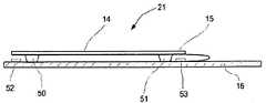
대부분의 실시예에서, 용량성 프레임(15)과 전극(21~24)으로 생성된 용량성 센서 각각은 동일 구조를 가질 것이다. 도 3a 내지 3c는 센서(21)와 같은 센서를 위한 일반 구조를 나타낸다. 도 3a를 참조하면, 이격된 컴플레인트(complaint) 지지 구조체(50,51)는 유리 커버(14)의 주변에 가장 가까운 PC 보드(16)와 유리 커버(14) 사이에 끼워진다. 이 지지 구조체(50,51)는 PC 보드(16) 상의 전극(52,53) 위로 이격되고 정렬되는 접지된 전도 프레임(15)의 일부로 커버(14)를 적재한다.In most embodiments, each of the capacitive frames 15 and the capacitive sensors produced by the electrodes 21-24 will have the same structure. 3A to 3C show a general structure for a sensor such as
지지 구조체(50,51)는 복수의 컴플레인트(complaint) 절연 물질로 형성될 수 있다. 실리콘, 고무, 및 폴리우레탄은 적절한 물질의 예이다.The
위에서 밝힌 바와 같이, 개인이 커버(14)를 터치하면, 부가된 힘의 크기와 위치에 따라 변화하는 각각의 센서(21~24)에서의 편향으로 유리 커버(14) 상의 힘의 위치와 크기에 좌우되는 양으로 편향한다. 도 3b는 동일하게 압박하는 지지 구조체(50,51) 사이에 힘을 생성하는 손가락 또는 스타일러스(54,stylus)에 의한 힘의 부가를 나타낸다. 결과적으로, 전극(52,53)과 외연하는 전도 프레임(15)의 일부는 하향 이동하여 전극 사이의 동일한 이격을 감소시키고 각 센서의 커패시턴스를 동일하게 증가시킨다.As indicated above, when an individual touches the
도 3c에 도시된 바와 같이, 스타일러스(54)가 지지 구조체(51) 가까이의 커버(14)를 누르면, 지지 구조체(50) 보다 더 압박한다. 도 3c에 도시된 바와 같이, 지지 구조체는 전도 프레임(15)과 전극(52) 사이에서 전극 사이 간격을 증가시키지만, 전도 프레임(15)과 전극(53) 사이의 전극 사이 간격은 감소한다. 결과적으로 전극(52)을 포함하는 센서의 커패시턴스는 감소하지만 전극(53)을 포함하는 센서의 커패시턴스는 감소한다. 합쳐서, 이들 신호는 힘이 도 3c의 오른쪽에 더 가깝게 부가된 것을 나타낸다.As shown in FIG. 3C, when the
도 4a에서 지지 구조체는 LCD(25) 위로 커버(15)를 이격하기 위한 스프링(61,62)을 포함한다. PC 보드(16)는 커버(14)의 에지와 정렬하는 위치에서 전극(62,63)을 지지한다. 본 실시예에서, 전기적으로 접지된 구조체(64)는 전극(65)을 적재하고; 유사한 구조체(66)는 전극(67)을 적재한다. 동작은 도 3a 내지 도 3c에 대해 묘사된 것과 본질적으로 동일하다. 이 구조는 선형 힘 편향 반응을 제공하는데 특히 이롭다. 도 1 및 도 2의 실시예에서 주변 전도 프레임이 일반적으로 금속 코팅으로 구성되지만, 코팅은 조립을 간단히 할 수 있는 금속 클립(64)으로 대치된다.In FIG. 4A, the support structure includes
도 4b는 PC 보드 또는 경질 기판(16)이 두껍고 LCD 디스플레이(25)를 위한 리세스로 형성되는 도 4a의 구조체의 변형을 설명한다. 이 케이스에서, PC 보드 또는 경질 기판(16)은 스프링(60,61)을 받는 웰(70,71)과 같은 웰을 통합하도록 또한 보정된다. 이 변형에서, 접지된 주변 전도 클립(64)은, 예를 들어, 전극으로 작용한다.4B illustrates a variation of the structure of FIG. 4A in which the PC board or
도 4a, 및 4b 각각은 프로세서(72)를 구비한 PC 보드(16)를 나타낸다. 그러한 프로세서의 추가는 임의의 외부 장치에 독립적으로 부가된 힘의 크기와 위치를 생성하도록 FST 스크린 및 RTID 및/또는 HAI 센서 모두로부터의 정보 처리를 가능하게 한다. 분명하듯이, 그러한 특징은 택틸 입력 장치와 외부 장치 사이에서 임의의 통신 링크를 위해 필요한 대역 폭을 감소시키는 하이-레벨 커맨드에 의해 외부 장치와의 통신을 허용한다.4A and 4B each show a
도 4a 및 4b가 회복력을 제공하는 스프링(60,61)을 개시하지만, 도 5a 내지 5c는 판 스프링을 결합한 다른 변형을 나타낸다. 도 5a에서, 힘은 PC 보드(16) 위로 이격된 커버(14)에 부가된다. 판 스프링(80)은 PC 보드(16)에 대하여 지탱하는 중심 부분(81)을 포함한다. 제 1 오프셋 윙(82)은 접지 전극(84)에 부착하는 패드(83)를 포함한다. 제 2 오프셋 윙(85)은 다른 접지 전극(87)에 부착하는 패드(86)를 포함한다. 전극(90,91) 상의 중심 부분(81)의 섹션은 센서를 완성하고, 본 특정 실시예에서, 주변 채널(92)은 얼마 정도의 강도를 제공하도록 PC 보드(16)에 부착한다. 플랜지(93)는 상향 이동을 제한하도록 커버(14) 위에 놓인다.While FIGS. 4A and 4B disclose
도 5b는 한 쌍의 판 스프링(100,101)이 커버(14)의 에지를 클립하는 제 1 접지부를 구비하는 변형 예를 나타낸다. 오프셋 부분(102,103)은 접지 접촉(104)과 맞물린다. 판 스프링(100.101)은 PC 보드(16)로부터 떨어져 커버를 바이어스한다. 채널(92)은 최대 간격을 구획한다. 센서 전극(105,106)과 기본적으로 동연하는 스프링(100,101) 부분은 센서를 완성한다.5B shows a variant in which the pair of
도 5a 및 5b에서, 판 스프링은 커버(14)와 PC 보드(16) 사이에 들어간다. 도 5c는 판 스프링(110,111)이 커버(14)에 접하고 센서 전극(114,115) 위에 놓이는 제 1 부분(112,113)을 구비하는 센서를 나타낸다. 부분(116,117)은 접지 전극(122) 각각에 부착하는 오프셋 패드(120,121)를 제공한다. 그러므로, 도 5c는 두 이격된 용량성 감지 구성요소를 포함하는 센서를 나타낸다.5A and 5B, the leaf springs enter between the
도 3a 내지 도 3c,도 4a,4b, 및 도 5a 내지 도 5c 각각은 두 용량성 센서를 나타낸다. 명백하듯이, FST(Force Sensitive Tactile) 스크린은 도 1 및 도 2 각각에서 위치 21 내지 24에서 4개의 센서 포인트를 제공하도록 커버의 사이드 또는 반대 단부 상에 2개의 그러한 구조체를 필요로 한다.3A-3C, 4A, 4B, and 5A-5C each show two capacitive sensors. As is apparent, the Force Sensitive Tactile (FST) screen requires two such structures on the side or opposite end of the cover to provide four sensor points at
물론, 센서 신호로부터 유래한 위치가 정확하도록 그러한 시스템을 조정할 필요가 있다. 그러한 조정 프로세스중 하나를 이해할 목적으로, 센서(21~24)는 BL(bottom left), TL(top left), TR(top right), BR(bottom right)을 가리키는 것으로 가정된다.Of course, such a system needs to be adjusted so that the position derived from the sensor signal is accurate. For the purpose of understanding one of such adjustment processes, sensors 21-24 are assumed to point to bottom left (BL), top left (TL), top right (TR), and bottom right (BR).
도 6에 도시된 바와 같이, 조정 프로세스(130)는 단계 131이 스크린의 각 코너에 대한 이상적인 위치값을 구축할 때 시작한다. 유닛 값을 사용하여, BL 코너에 대한 이상적인 위치 값은 0,0; TL 코너는 0,1; TR 코너는 1,1; BR 코너는 1,0이다.As shown in FIG. 6, the
힘이 코너 0,0에 부가된 후, 단계 132는 원시(raw) 접촉 중심 위치를 원하는 0,0으로 변환한다. 예를 들어, BL 코너가 눌러지면, 결과 중심 값은 0,0으로 설정된다. 단계 133은 두 인접 센서에 대한 보정 기준을 생성하도록 선형 변환(linear transformation)을 실행한다. 그것은 본 실시예에서 TL 및 BR 코너이다. 단계 134는 남은 대각선 반대 위치, 즉, 본 실시예에서 TR 코너에 대한 보정 기준을 생성하도록 비-선형 변환을 실행한다.After the force is added to corner 0,0, step 132 converts the raw contact center position to the desired 0,0. For example, if the BL corner is pressed, the resulting center value is set to 0,0. Step 133 performs a linear transformation to generate calibration criteria for two adjacent sensors. It is the TL and BR corners in this embodiment. Step 134 performs a non-linear transformation to generate a correction criterion for the remaining diagonally opposite position, that is, the TR corner in this embodiment.
일단 단계 132 내지 134의 측정과 변환이 완료되면, 단계 135는 도 4a, 4b의 온-보드 프로세서(72)와 같은 프로세서에 보정 기준을 저장할 수 있다. 그 후, 이들 기준은 센서 판독시 임의의 변화를 보정하는 데 사용된다.Once the measurements and conversions of steps 132-134 are completed,
이제 올바르게 인식되듯이, 도 3a ~ 5c의 특정 실시예와 관련된 여러 실시예는 다른 입력으로 힘 감지 터치 스크린을 통합한 여러 택틸 입력 장치를 나타낸다. 힘 감지 터치 스크린은 디스플레이 스크린 없이 경질 입력 장치를 형성하기 위해 적용될 수도 있다. 또한, 본 발명을 실행할 수 있고 특정 애플리케이션에 맞추어져도 좋은 여러 용량성 센서 구조체가 설명되었다.As is now correctly recognized, various embodiments associated with the specific embodiments of FIGS. 3A-5C represent various tactyl input devices incorporating a force sensing touch screen with different inputs. Force sensitive touch screens may be applied to form rigid input devices without display screens. In addition, various capacitive sensor structures have been described that may be practiced with the present invention and may be tailored to particular applications.
위의 도면에서 도시된 발명은 타블릿 입력 장치 및 멀티-터치 입력 장치와 같은 다른 애플리케이션을 가질 수 있다는 것 또한 알려졌다. 타블릿 입력 장치 실시예는 예를 들어 쓰여진 또는 그래픽 이미지를 기록하는 스타일러스를 통해 부가되는 것과 같은 입력 힘의 변환의 임의의 움직임을 기록하도록 적용될 수 있다. 멀티-터치 입력 장치는 둘 이상의 개인 손가락에 의해 동시에 터치되는 것과 같이, 입력 장치에 동시에 부가되는 복수의 힘의 위치를 분별하는 능력을 제공한다.It is also known that the invention shown in the above figures can have other applications, such as tablet input devices and multi-touch input devices. Tablet input device embodiments may be adapted to record any movement of a transformation of input force, such as, for example, added through a stylus that records a written or graphical image. Multi-touch input devices provide the ability to discern locations of a plurality of forces simultaneously being added to the input device, such as being simultaneously touched by two or more individual fingers.
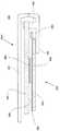
도 7 은 본 발명이 개인이 장치상에 "쓰고", "쓴것"을 디스플레이하도록 이용하는 입력 및 디스플레이 장치(140)를 나타낸다. 도 7은 아래 놓인, 기준 면을 구획하는 PC 보드(141) 및 개인이 스타일러스 또는 다른 “쓰기” 도구를 이용할 수 있는 입력 수단 역할을 하는 유리 커버(142)를 나타낸 장치(140)의 상면도를 제공한다. 굴곡(143a ~ 143D)은 PC 보드(141)와 유리 커버(143) 사이 간격에 변화를 생성하는 “쓰기” 프로세스를 허용하는 데 필요한 굴곡을 제공한다.7 illustrates an input and
도 7에 도시된 바와 같이, 장치(140)는 센서 위치의 어레이를 구획한다. 이 특정 실시예에서, 12개의 위치는 3x4 센서 위치(144a~144L) 어레이를 구획한다. 도 8 ~ 10에 관해 더욱 상세히 설명되듯이, 각각의 위치는 PC 보드(141)와 유리 커버(142) 사이의 각격에 임의의 변화는 커패시턴스 값에 상응하는 변화를 생성하도록 커패시터를 한정하는 전극에 의해 특징 지워진다.As shown in FIG. 7, the
전력 연결(145)과 데이터 연결(146)은 시스템에 전력을 제공하고, 적절하게 프로그래밍된 디지털 컴퓨터와 같은 신호 프로세서가 커패시턴스 감지 IC(147)를 통해 유리 커버(142)의 터치에 의해 생성된 힘과 위치 모두를 식별할 수 있는 신호를 검색한다. 이 출력을 제공하기 위해 적용될 수 있는 많은 알고리즘이 있다. 그러한 알고리즘 하나로 커패시턴스에 있어서의 변화는 각 위치에 대한 중심 값을 제공하고, 개별적인 중심 값은 그 다음 부가된 힘의 x-y 위치와 그 힘의 크기를 식별하는 결과 신호를 제공하도록 결합될 수 있다. 중력 감지 가속도계(148)는 장치가 중력 벡터에 대하여 틸트되는 데에 따라 입력 구조체(142)의 중량을 보상할 수 있다. 가속도계(148)는 장치가 운송중 진동을 겼었을 경우 힘 감지 구성 요소를 무시하거나 필터를 보상하는 데 사용될 수도 있다.
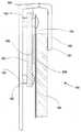
도 8 은 도 7을 참조하여 위에서 설명된 기능을 제공할 수 있는 장치의 특정 실시예의 일부를 나타낸다. 이 실시예(150)는 PC 보드(1410를 지지하도록, 스탠드오프(152)와 같은 복수의 스탠드오프를 포함하는 인클로저 베이스(151, enclosure base)를 포함한다. PC 보드(141)는 기준면(153)을 한정한다. 다른 스페이서(154)는 부착되는 유리 커버(142) 주변 넘어 전자 차폐(155)의 연장에 위치한다. 스크류(156)와 같은 패스너가 지지 구조체를 완성한다. L-형상 주변 인클로저 커버는 이 구조체를 보호하고 아래 놓이고, 컴플레인트 또는 소프트 씰(158)은 상향 움직임의 한계 및 장치(150)의 내부로 파편 침투에 대한 배리어를 제공한다.FIG. 8 illustrates a portion of a particular embodiment of an apparatus capable of providing the functionality described above with reference to FIG. 7. This
도 8 및 다른 도면은 단일 구성요소로 커버(142)를 나타낸다. 그러나, 본 발명의 여러 실행에서, 커버(142)는 보호 유리 커버와 전자 차폐 사이에 전자 종이(ePaper) 디스플레이와 같은 완전 디스플레이를 포함할 것이다. 그러므로, 다음 설명에서 “유리 커버”의 참조는 그러한 커버 또는 커버와 디스플레이의 통합을 포함하고자 한다.8 and other figures show the
도 8 은 또한 하나의 센서 위치(144n)를 나타낸다. 이 위치에서, 제 1 전극(160)은 전자 차폐(155) 상에 형성되고 기준면(153) 상에 형성된 제 2 전극 위로 이격된다. 본 실시예에서, 제 1 전극은 유리 커버(142)와 움직이지만 제 2 전극(161)은 움직이지 않고 남아있는다. 전극(160,161)은 구성요소와 개별 전도체를 분리하듯이 공통 연결에 형성될 수 있다. 대안으로, 전극(160)은 하나의 어레이의 횡 및 열과 정렬되는 이격 평행 스트립으로 구성될 수 있지만, 전극(161)은 다른 어레이의 횡 및 열과 정렬되는 이격 평행 스트립으로 구성된다. 이 접근은 둘 이상의 포인트 멀티-터치 감지 능력을 허용하는 플렉시블 디스플레이와 관련하여 유용한 고해상도 압력 맵을 제공하는 동안 전극과 신호 프로세서 사이의 상호 연결의 수를 감소시키고 간단히 할 수 있다.8 also shows one
위의 설명으로부터, 개인이 유리 커버(142)를 누르면, 유리 커버(142)가 눌러진 위치에 따른 방향으로 편향된다는 것이 분명할 것이다. 힘이 유리 커버(142)의 정확한 중심에 부가되지 않으면 상이한 센서 위치의 전극 사이 간격은 각 센서 위치로부터 신호 또한 상이해지도록 상이해질 것이다. 일부 상황에서 일부 센서 위치의 전극 사이의 간격 또는 갭은 터치에 상응하여 감소할 것이고; 다른 위치의 갭이 증가해도 좋고; 또 다른 갭은 본질적으로 변화하지 않고 남아있어도 좋다. 그러나, 집합적으로 센서는 힘의 위치를 결정하는 충분한 정보를 제공할 것이다.From the above description, it will be apparent that when an individual presses the
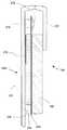
도 9는 도 7을 참조하여 위에서 설명된 기능을 제공할 수 있는 장치의 제 2 실시예의 일부분을 나타낸다. 본 실시예(170)는 PC 보드(141)를 지지하기 위한 스탠드오프(172)와 같은 복수의 스탠드오프를 구비한 인클로저 베이스(171)를 포함한다. PC 보드(141)는 기준면(173)을 한정한다. 다른 스페이서(174)는 부착하는 유리 커버(142)의 주변을 너머 전자 차폐(175)의 연장에 위치한다. 스크류(176)와 같은 패스너는 지지 구조체를 완성한다. L-형상 주변 인클로저 커버(177)는 이 구조체 위에 놓여 구조체를 보호한다.9 shows a portion of a second embodiment of an apparatus capable of providing the functionality described above with reference to FIG. 7. This
도 9는 하나의 센서 위치(144n)도 나타낸다. 이 위치에서, 제 1 전극은 고체 및 연속 접지 플레이트와 같은 전자 차폐(175)에 의해 형성된다. 기준면(173) 상에 형성된 제 2 전극(178) 위로 이격된다. 본 실시예에서, 제 1 전극은 접지 전극으로 역할하고 유리커버(142)와 이동하지만 제 2 전극(178)은 움직이지 않고 남아있는다. 전극(178)은 경질의 또는 플렉시블 PCB 또는 플라스틱 필름 상에 인쇄된 전도 잉크에 의해 형성되듯이 개별 전도체를 구비한 분리 구성요소로 형성된다. 어떠한 형태에서든, 이들은 커패시턴스 감지 IC(147) 또는 유사 컴포넌트 또는 회로에 연결한다.9 also shows one
위에 설명한 것으로부터, 유리 커버(142)는 힘이 부가하는 것에 의해 각각의 제 2 전극(178)을 구비한 접지 평면의 관계를 변화시킬 때 편향할 것이다. 다시, 집합적으로 신호는 유리 플레이트의 힘의 위치를 결정하도록 충분한 정보를 제공할 것이다.From what has been described above, the
도 10은 도 7을 참조하여 위에서 설명된 기능을 제공할 수 있는 장치의 제 3 실시예의 일부분을 나타낸다. 본 실시예(180)는 전자 차폐(185)와 L-형상 주변 인클로저 커버(187)를 포함하는 유리 커버(142)와 PC 보드(141)를 지지하는 인클로저 베이스(181)를 포함한다. 본 실시예에서, 182에 도시된 바와 같은 스탠드오프와 스크류가 유리 커버(142)를 구비한 전자 차폐(185)를 지지하고 필요한 굴곡을 제공하는 커버(187)에 매달린다. 프레이서(184)와 같은 다른 스탠드오프들 또한 기준면(183)을 가진 PC 보드(141)을 배치하도록 커버(182)에 매달린다.FIG. 10 illustrates a portion of a third embodiment of an apparatus capable of providing the functionality described above with reference to FIG. 7. This embodiment 180 includes a
본 실시예에서, 센서 위치(144n)의 센서의 구조체는 전자 차폐(185) 상에 형성된 제 1 전극(189)을 포함한다. 본 구조체는 구조 프레임(187)을 사용하는 것에 의해 전극 간격을 더 잘 조절할 수 있다. 본 구성에서, 전자 차폐(185) 및 전극(189)은 기준면(183) 상에 형성된 전극(188)과 같은 제 2 전극 위로 이격된 분리 접지 전극들을 형성한다. 전극(188)은 공통 연결에 분리 구성요소를 구비한 개별 전도체로 형성된다.In this embodiment, the structure of the sensor at the
위에 설명한 것으로부터, 유리 커버(142)는 힘이 부가하는 것에 의해 각각의 제 2 전극(188)을 구비한 접지 평면의 관계를 변화시킬 때 편향할 것이다. 다시, 집합적으로 신호는 유리 플레이트의 힘의 위치를 결정하도록 충분한 정보를 제공할 것이다.From what has been described above, the
도 11은 도 7을 참조하여 위에서 설명된 기능을 제공할 수 있는 장치의 다른 실시예의 일부분을 나타낸다. 본 실시예(190)는 전자 종이 디스플레이 대신 LCD 디스플레이 유닛(196)을 지지하는 인클로저 베이스(191)를 포함한다. LCD는 전자 차폐 프레임(195)과 L-형상 주변 인클로저 커버(197)를 포함한다. 본 실시예에서, 스탠드오프(192,194)와 같은 스탠드오프와 스크류는 함께 나사로 죄어지고, 전자 차폐(195)를 지지하고 LCD 디스플레이(196)를 위하여 필요한 굴곡을 제공하도록 베이스(191)로부터 연장한다.FIG. 11 illustrates a portion of another embodiment of an apparatus capable of providing the functionality described above with reference to FIG. 7. This
본 실시예에서, 센서의 구조체는 LCD 시트 금속에 의해 형성되는 제 1 전극과 베이스(191)에 설치되고 LCD 프레임(196)의 굴곡(195)을 지지하는 작은 PC 보드(193) 상의 제 2 전극을 포함한다. 복 구성에서, LCD는 반대 방향에서 마주하게 설치하여 LCD 상의 부가된 힘은 그것을 압박하는 대신 199와 200 사이의 갭을 확장한다.In this embodiment, the structure of the sensor is a first electrode formed by the LCD sheet metal and a second electrode on the
도 12는 도 7을 참조하여 위에서 설명된 기능을 제공할 수 있는 장치의 다른 실시예의 일부분을 나타낸다. 본 실시예(210)는 전자 종이 디스플레이 대신 LCD 디스플레이 유닛(196)을 지지하는 인클로저 베이스(211)를 포함한다. LCD는 전자 차폐 프레임(215)과 L-형상 주변 인클로저 커버(217)를 포함한다. 본 실시예에서, 스탠드오프(212)와 스크류(216)와 같은 스탠드오프와 스크류는 전자 차폐(215)를 지지하고 LCD 디스플레이(196)를 위해 필요한 굴곡을 제공하도록 베이스(211)로부터 연장한다.FIG. 12 illustrates a portion of another embodiment of an apparatus capable of providing the functionality described above with reference to FIG. 7. This embodiment 210 includes an
본 실시예에서, 센서 위치(144n)의 센서의 구조체는 PC 보드(214)의 바다 상에 형성되고 인클로저(211)로부터 이격된 제 1 전극(219)을 포함한다. 베이스(211)는 각 센서 위치에 대하여 제 2 또는 접지 전극으로 역할을 하는 금속화된 상부 표면(218)을 구비한다. 이 구성에서, 금속화된 표면(218)은 전체 LCD 디스플레이 아래 놓인 연속 접지 전극이지만, 전극(219)은 금속화된 상면 위로 이격된 분리 전극을 형성한다.In this embodiment, the structure of the sensor at the
도 8은 배리어(158)를 나타낸다. 도 11의 본 실시예에서, 박막 더스트 씰(198)이 인클로저 커버(197)의 단부와 LCD 장치(196) 사이에 위치한다. 그러한 씰은 인클로저 커버(197)와 LCD(196)의 상응하는 표면으로의 부착에 의해 부착될 수 있다. 이는 LCD 디스플레이(196)의 움직임을 바이어스하거나 제한하지 않고 장치의 내부 부분에 파편의 축적을 방지하는 양의 배리어를 제공한다.8 shows a
위에 설명한 것으로부터, LCD 디스플레이(196)는 힘이 부가하는 것에 의해 각각의 제 2 전극(219)을 구비한 접지 평면(281)의 관계를 변화시킬 때 편향할 것이다. 다시, 집합적으로 신호는 유리 플레이트의 힘의 위치를 결정하도록 충분한 정보를 제공할 것이다.From what has been explained above, the
요약하면, LCD 디스플레이 장치 또는 전자 종이 디스플레이 장치 위에 설치되는 경질 투명 레이어로 형성되는 힘-감지 터치 스크린을 구비한 택틸 장치에 대한 복수의 실 예가 되는 실시예가 설명되었다. 위에서 밝혔듯이, 일부 애플리케이션에서 터치 스크린은 터치 스크린의 상이한 부분에 복수의 터치를 기록하고 디스플레이 할 수 있도록 변형가능해도 좋다. 전자 종이와 LCD 디스플레이가 특별히 설명되었지만, 유기 LED 디스플레이와 같은 다른 디스플레이 장치가 대체될 수 있다. 터치 및 기준 면과 굴곡 기능을 제공하는 컴포넌트의 상이한 구성은 임의의 특별히 개시된 실시예를 대신할 수 있다. 상이한 용량성 센서 구성은 본 발명으로 사용을 위해 채용될 수 있다.In summary, a number of illustrative embodiments have been described for a tactile device having a force-sensitive touch screen formed of a rigid transparent layer installed over an LCD display device or an electronic paper display device. As noted above, in some applications the touch screen may be deformable to record and display multiple touches on different portions of the touch screen. Although electronic paper and LCD displays have been specifically described, other display devices such as organic LED displays can be replaced. Different configurations of components that provide touch and reference planes and bending functions may replace any specially disclosed embodiment. Different capacitive sensor configurations can be employed for use with the present invention.
본 발명의 실시예는, 디스플레이의 품질을 열화시킬 수 있는 디스플레이 위의 ITO와 같은 투명 전도 물질의 사용을 생략하는 추가적인 이익을 제공할 수 있다. ITO는 제한된 리소스이고 환경친화적이지 않다. e-북과 같은 터치 스크린 애플리케이션을 위해, ITO 레이어의 생략은 이 열화를 제거하는 것에 의해 상당한 이익을 제공한다.Embodiments of the present invention may provide the additional benefit of omitting the use of transparent conductive materials such as ITO on the display, which may degrade the quality of the display. ITO is a limited resource and not environmentally friendly. For touch screen applications such as e-books, the omission of the ITO layer provides a significant benefit by eliminating this degradation.
본 발명은 그러한 실시예로 설명된다. 여러 변경이 본 발명에서 벗어나지 않고 설명된 장치로 만들어질 수 있다는 것이 명백하다. 그러므로, 본 발명은 본 발명의 주제와 범위 안에서 나오는 바와 같은 모든 변형과 변경을 커버한다.The present invention is illustrated by such an embodiment. It is apparent that various modifications can be made to the described apparatus without departing from the invention. Therefore, the present invention covers all modifications and variations as come within the spirit and scope of the invention.
Claims (18)
Translated fromKoreanA) 기준 표면을 구획하는 기준 수단;
B) 힘이 가해지는 입력 수단;
C) 상기 입력 수단이 상기 기준 수단에 대하여 휘어지는 것에 의해 상기 힘의 부가에 반응할 수 있도록 하는 굴곡 밀착 수단;
D) 상기 기준 수단에 대하여 상기 입력 수단의 동작을 감지하고, i) 상기 기준 수단에 대하여 상기 입력 수단과 함께 움직이는 제 1 전극 수단, 및 ⅱ) 상기 제 1 전극 수단과 이격되고 상기 기준 수단에 부착되는 제 2 전극 수단을 포함하는 용량성 감지 수단; 및
E) 상기 제 1 및 제 2 전극 수단에 연결되어 상기 기준 표면에 대하여 상기 입력 수단의 상기 굴곡에 응답하여 상기 입력 수단에 부가된 상기 힘에 비례하는 신호를 생성하는 신호 처리 수단을 포함하는 것을 특징으로 하는 감지 터치 반응 입력 장치.In a force sensing touch response input device,
A) reference means for partitioning the reference surface;
B) force input means;
C) flexing contact means for allowing the input means to react to the addition of the force by bending relative to the reference means;
D) detecting the operation of said input means with respect to said reference means, i) first electrode means moving with said input means with respect to said reference means, and ii) spaced apart from said first electrode means and attached to said reference means; Capacitive sensing means comprising second electrode means; And
E) signal processing means connected to said first and second electrode means for generating a signal proportional to said force added to said input means in response to said bending of said input means with respect to said reference surface; Sensing touch response input device.
상기 제 1 및 제 2 전극 수단은 상기 기준 수단 및 상기 입력 수단의 주변에 대하여 기설정된 위치에 복수의 불연속 센서를 형성하는 것을 특징으로 하는 힘 감지 터치 반응 입력 장치.The method of claim 1,
And the first and second electrode means form a plurality of discontinuous sensors at predetermined positions with respect to the periphery of the reference means and the input means.
상기 입력 수단은 상기 굴곡 밀착 수단에 의해 지지되는 경질 유리 플레이트를 포함하는 것을 특징으로 하는 힘 감지 터치 반응 입력 장치.The method of claim 2,
And the input means comprises a hard glass plate supported by the bending contact means.
상기 굴곡 밀착 수단은 상기 기준 수단과 상기 유리 플레이트 사이에 있는 복수의 굴곡을 포함하는 것을 특징으로 하는 힘 감지 터치 반응 입력 장치.The method of claim 3, wherein
And said bending contact means comprises a plurality of bends between said reference means and said glass plate.
상기 굴곡은 준수 구조체(compliant structures)를 포함하는 것을 특징으로 하는 힘 감지 터치 반응 입력 장치.The method of claim 4, wherein
And said flexure comprises compliant structures.
상기 준수 구조체는 몰딩된 실리콘 구조체를 포함하는 것을 특징으로 하는 힘 감지 터치 반응 입력 장치.The method of claim 5, wherein
And the conforming structure comprises a molded silicon structure.
상기 준수 구조체는 압축 스프링을 포함하는 것을 특징으로 하는 힘 감지 터치 반응 입력 장치.The method of claim 5, wherein
And the compliant structure comprises a compression spring.
상기 준수 구조체는 판 스프링(leaf spring)을 포함하는 것을 특징으로 하는 힘 감지 터치 반응 입력 장치.The method of claim 5, wherein
And the compliant structure comprises a leaf spring.
상기 용량성 감지 수단은 상기 기준 수단과 상기 입력 수단 사이에 배치되어 센서 위치의 어레이를 구획하는 제 1 및 제 2 추가 전극을 포함하고,
상기 신호 처리 수단은 상기 어레이 내의 상기 전극 수단에 연결되어 상기 입력 수단에 부가되는 상기 전체 힘과 임의의 터치의 위치를 가리키는 신호를 생성하는 것을 특징으로 하는 힘 감지 터치 반응 입력 장치.The method of claim 2,
The capacitive sensing means comprise first and second additional electrodes disposed between the reference means and the input means to define an array of sensor locations,
And said signal processing means is connected to said electrode means in said array to generate a signal indicative of the location of any touch and the total force added to said input means.
상기 입력 수단은 플레이트를 포함하는 것을 특징으로 하는 힘 감지 터치 반응 입력 장치.The method of claim 7, wherein
And the input means comprises a plate.
상기 기준 수단은 상기 플레이트를 위한 평면 받침을 구비한 인클로저를 포함하고,
상기 굴곡 밀착 수단은 상기 기준 수단의 주변 주위에 배치되는 복수의 굴곡을 포함하는 것을 특징으로 하는 힘 감지 터치 반응 입력 장치.The method of claim 8,
The reference means comprises an enclosure with a planar foot for the plate,
And said bending contact means comprises a plurality of bends arranged around the periphery of said reference means.
상기 복수의 굴곡은 4개인 것을 특징으로 하는 힘 감지 터치 반응 입력 장치.The method of claim 10,
And a plurality of bends of the force sensing touch response input device.
상기 플레이트는 전기 차폐를 포함하고,
상기 제 1 전극은 상기 전기 차폐로 형성되고, 상기 제 2 전극은 평면 받침에 부착되는 것을 특징으로 하는 힘 감지 터치 반응 입력 장치.The method of claim 10,
The plate comprises an electrical shield,
And the first electrode is formed by the electrical shield, and the second electrode is attached to a flat base.
상기 평면 받침은 PCB(Printed Circuit Board)를 포함하는 것을 특징으로 하는 힘 감지 터치 반응 입력 장치.The method of claim 12,
The planar foot is a force sensing touch response input device comprising a printed circuit board (PCB).
상기 플레이트는 변형 가능하고 상기 신호 처리 수단은 상기 플레이트의 복수의 터치를 나타내는 신호를 생성하는 것을 특징으로 하는 힘 감지 터치 반응 입력 장치.The method of claim 12,
The plate is deformable and the signal processing means generates a signal indicative of a plurality of touches of the plate.
상기 입력 수단은 LCD 디스플레이를 포함하는 것을 특징으로 하는 힘 감지 터치 반응 입력 장치.The method of claim 12,
And said input means comprises an LCD display.
상기 입력 수단은 전자 종이(e-paper) 디스플레이를 포함하는 것을 특징으로 하는 힘 감지 터치 반응 입력 장치.The method of claim 12,
And said input means comprises an electronic paper display.
상기 입력 수단은 유기 LED 디스플레이를 포함하는 것을 특징으로 하는 힘 감지 터치 반응 입력 장치.
The method of claim 12,
And the input means comprises an organic LED display.
Applications Claiming Priority (4)
| Application Number | Priority Date | Filing Date | Title |
|---|---|---|---|
| US4067208P | 2008-03-30 | 2008-03-30 | |
| US61/040,672 | 2008-03-30 | ||
| US12/412,504 | 2009-03-27 | ||
| US12/412,504US8169332B2 (en) | 2008-03-30 | 2009-03-27 | Tactile device with force sensitive touch input surface |
Publications (2)
| Publication Number | Publication Date |
|---|---|
| KR20100136990Atrue KR20100136990A (en) | 2010-12-29 |
| KR101566571B1 KR101566571B1 (en) | 2015-11-05 |
Family
ID=41116254
Family Applications (1)
| Application Number | Title | Priority Date | Filing Date |
|---|---|---|---|
| KR1020107024369AExpired - Fee RelatedKR101566571B1 (en) | 2008-03-30 | 2009-03-28 | Tactile Device with Force Sensitive Touch Input Surface |
Country Status (4)
| Country | Link |
|---|---|
| US (1) | US8169332B2 (en) |
| EP (1) | EP2266018A4 (en) |
| KR (1) | KR101566571B1 (en) |
| WO (1) | WO2009146006A1 (en) |
Cited By (2)
| Publication number | Priority date | Publication date | Assignee | Title |
|---|---|---|---|---|
| KR20190083927A (en)* | 2018-01-05 | 2019-07-15 | 현대자동차주식회사 | Touch control device and vehicle comprising the same |
| KR20220140000A (en)* | 2020-03-03 | 2022-10-17 | 센셀, 인크. | Systems and methods for detecting and characterizing touch input in a human-computer interface |
Families Citing this family (128)
| Publication number | Priority date | Publication date | Assignee | Title |
|---|---|---|---|---|
| US9329719B2 (en) | 2007-03-15 | 2016-05-03 | Apple Inc. | Hybrid force sensitive touch devices |
| WO2008115408A1 (en)* | 2007-03-15 | 2008-09-25 | F-Origin, Inc. | Integrated feature for friction-less movement of force sensitive touch screen |
| DE102008019642A1 (en)* | 2008-04-18 | 2009-10-22 | Siemens Aktiengesellschaft | Outdoor vending machine and use of a user interface for operating an outdoor vending machine |
| US20100102830A1 (en)* | 2008-10-27 | 2010-04-29 | Microchip Technology Incorporated | Physical Force Capacitive Touch Sensor |
| US8858003B2 (en) | 2008-10-27 | 2014-10-14 | Microchip Technology Incorporated | Physical force capacitive touch sensors having conductive plane and backlighting |
| TWI412968B (en)* | 2008-12-25 | 2013-10-21 | Nissha Printing | Touch panel having press detection function and pressure sensitive sensor for the touch panel |
| GB2468275A (en)* | 2009-02-16 | 2010-09-08 | New Transducers Ltd | A method of making a touch-sensitive data entry screen with haptic feedback |
| US9024907B2 (en)* | 2009-04-03 | 2015-05-05 | Synaptics Incorporated | Input device with capacitive force sensor and method for constructing the same |
| CA2699363A1 (en)* | 2009-04-16 | 2010-10-16 | Research In Motion Limited | Electronic device and touch screen display with force sensor |
| US8289290B2 (en) | 2009-07-20 | 2012-10-16 | Sony Ericsson Mobile Communications Ab | Touch sensing apparatus for a mobile device, mobile device and method for touch operation sensing |
| US8621942B2 (en)* | 2009-08-03 | 2014-01-07 | Atmel Corporation | Force sensor with compressible electrode |
| CN102483665B (en)* | 2009-08-31 | 2014-12-10 | 日本写真印刷株式会社 | Mount structure of touch panel with vibrating function |
| US9543948B2 (en) | 2009-09-01 | 2017-01-10 | Microchip Technology Incorporated | Physical force capacitive touch sensors |
| TWI395127B (en)* | 2009-09-29 | 2013-05-01 | Mstar Semiconductor Inc | Capacitive sensing apparatus and method applied to touch screen |
| JP5026486B2 (en)* | 2009-09-29 | 2012-09-12 | 日本写真印刷株式会社 | Mounting structure of touch input device with pressure sensitive sensor |
| US10068728B2 (en)* | 2009-10-15 | 2018-09-04 | Synaptics Incorporated | Touchpad with capacitive force sensing |
| JP5347913B2 (en)* | 2009-11-06 | 2013-11-20 | ソニー株式会社 | SENSOR DEVICE, ELECTRONIC DEVICE, AND METHOD FOR MANUFACTURING SENSOR DEVICE |
| US9057653B2 (en)* | 2010-05-11 | 2015-06-16 | Synaptics Incorporated | Input device with force sensing |
| EP2390766B1 (en)* | 2010-05-28 | 2013-09-25 | BlackBerry Limited | Electronic device including touch-sensitive display and method of controlling same |
| EP2390767A1 (en)* | 2010-05-28 | 2011-11-30 | Research In Motion Limited | Electronic device including touch-sensitive display and method of controlling same |
| US8669946B2 (en) | 2010-05-28 | 2014-03-11 | Blackberry Limited | Electronic device including touch-sensitive display and method of controlling same |
| CN102271181B (en)* | 2010-06-04 | 2014-10-22 | 深圳富泰宏精密工业有限公司 | Mobile phone with electronic scale function and weighing quoting method thereof |
| JP5813103B2 (en) | 2010-06-11 | 2015-11-17 | スリーエム イノベイティブ プロパティズ カンパニー | Touch position sensor with force measurement |
| US9182820B1 (en) | 2010-08-24 | 2015-11-10 | Amazon Technologies, Inc. | High resolution haptic array |
| US20120090757A1 (en) | 2010-10-18 | 2012-04-19 | Qualcomm Mems Technologies, Inc. | Fabrication of touch, handwriting and fingerprint sensor |
| CN103180799B (en)* | 2010-11-12 | 2016-02-03 | 京瓷株式会社 | Electronic equipment and there is the portable terminal of this electronic equipment |
| US20120120017A1 (en)* | 2010-11-17 | 2012-05-17 | Synaptics Incorporated | System and method for determining object information using an estimated deflection response |
| US8618428B2 (en) | 2010-12-14 | 2013-12-31 | Synaptics Incorporated | System and method for determining object information using an estimated rigid motion response |
| JP2012141844A (en)* | 2011-01-04 | 2012-07-26 | Fujitsu Component Ltd | Touch panel |
| US9389721B2 (en)* | 2011-02-09 | 2016-07-12 | Apple Inc. | Snap domes as sensor protection |
| US9557857B2 (en) | 2011-04-26 | 2017-01-31 | Synaptics Incorporated | Input device with force sensing and haptic response |
| US9748952B2 (en)* | 2011-09-21 | 2017-08-29 | Synaptics Incorporated | Input device with integrated deformable electrode structure for force sensing |
| US10088863B2 (en) | 2011-09-30 | 2018-10-02 | Apple Inc. | Electronic devices with cover layers mounted to displays |
| WO2013049816A1 (en) | 2011-09-30 | 2013-04-04 | Sensitronics, LLC | Hybrid capacitive force sensors |
| US9098242B2 (en)* | 2011-09-30 | 2015-08-04 | Apple Inc. | Electronic devices with cover layers mounted to displays |
| EP2766895A4 (en)* | 2011-10-14 | 2015-07-15 | Nextinput Inc | Force sensitive interface device and methods of using same |
| US9041418B2 (en) | 2011-10-25 | 2015-05-26 | Synaptics Incorporated | Input device with force sensing |
| US9229550B1 (en)* | 2011-11-29 | 2016-01-05 | Amazon Technologies, Inc. | Physically modifying a configurable user interface |
| US9665214B2 (en) | 2012-03-29 | 2017-05-30 | Synaptics Incorporated | System and methods for determining object information using selectively floated electrodes |
| US9410841B2 (en)* | 2012-03-30 | 2016-08-09 | Ncr Corporation | Integrated scanner, scale, and touchscreen display |
| US9223162B2 (en) | 2012-04-11 | 2015-12-29 | Apple Inc. | Display having a flexured element |
| US9024910B2 (en) | 2012-04-23 | 2015-05-05 | Qualcomm Mems Technologies, Inc. | Touchscreen with bridged force-sensitive resistors |
| WO2013170099A1 (en) | 2012-05-09 | 2013-11-14 | Yknots Industries Llc | Calibration of haptic feedback systems for input devices |
| WO2013169299A1 (en) | 2012-05-09 | 2013-11-14 | Yknots Industries Llc | Haptic feedback based on input progression |
| WO2013177322A1 (en) | 2012-05-22 | 2013-11-28 | Synaptics Incorporated | Force enhanced input device |
| WO2013188307A2 (en) | 2012-06-12 | 2013-12-19 | Yknots Industries Llc | Haptic electromagnetic actuator |
| US9493342B2 (en) | 2012-06-21 | 2016-11-15 | Nextinput, Inc. | Wafer level MEMS force dies |
| EP2870445A1 (en) | 2012-07-05 | 2015-05-13 | Ian Campbell | Microelectromechanical load sensor and methods of manufacturing the same |
| US9329314B2 (en) | 2012-07-13 | 2016-05-03 | Apple Inc. | Touch screen display with transparent electrical shielding layer |
| WO2014018121A1 (en) | 2012-07-26 | 2014-01-30 | Changello Enterprise Llc | Fingerprint-assisted force estimation |
| WO2014018086A1 (en)* | 2012-07-26 | 2014-01-30 | Changello Enterprise Llc | Force correction on multiple sense elements |
| WO2014018116A1 (en) | 2012-07-26 | 2014-01-30 | Changello Enterprise Llc | Ultrasound-based force sensing and touch sensing |
| WO2014018115A1 (en) | 2012-07-26 | 2014-01-30 | Changello Enterprise Llc | Ultrasound-based force sensing of inputs |
| US9886116B2 (en)* | 2012-07-26 | 2018-02-06 | Apple Inc. | Gesture and touch input detection through force sensing |
| US20140038524A1 (en)* | 2012-07-31 | 2014-02-06 | Research In Motion Limited | Method and apparatus pertaining to the timing of stylus location transmissions |
| WO2014035479A2 (en) | 2012-08-30 | 2014-03-06 | Changello Enterprise Llc | Auto-baseline determination for force sensing |
| US20140085213A1 (en)* | 2012-09-21 | 2014-03-27 | Apple Inc. | Force Sensing Using Bottom-Side Force Map |
| US9891759B2 (en) | 2012-09-28 | 2018-02-13 | Apple Inc. | Frustrated total internal reflection and capacitive sensing |
| JP5898779B2 (en)* | 2012-10-11 | 2016-04-06 | アルプス電気株式会社 | INPUT DEVICE AND METHOD FOR DETECTING MULTI-POINT LOAD USING THE INPUT DEVICE |
| US10817096B2 (en)* | 2014-02-06 | 2020-10-27 | Apple Inc. | Force sensor incorporated into display |
| DE112013005988B4 (en) | 2012-12-14 | 2023-09-21 | Apple Inc. | Force detection through changes in capacity |
| KR20150113169A (en) | 2013-02-08 | 2015-10-07 | 애플 인크. | Force determination based on capacitive sensing |
| JP6119518B2 (en)* | 2013-02-12 | 2017-04-26 | ソニー株式会社 | Sensor device, input device and electronic apparatus |
| US9304587B2 (en) | 2013-02-13 | 2016-04-05 | Apple Inc. | Force sensing mouse |
| US9229592B2 (en) | 2013-03-14 | 2016-01-05 | Synaptics Incorporated | Shear force detection using capacitive sensors |
| US9851828B2 (en) | 2013-03-15 | 2017-12-26 | Apple Inc. | Touch force deflection sensor |
| KR101992340B1 (en)* | 2013-03-27 | 2019-06-25 | 삼성디스플레이 주식회사 | Window and display device |
| WO2014190293A2 (en)* | 2013-05-24 | 2014-11-27 | New York University | Haptic force-feedback for computing interfaces |
| US9671889B1 (en) | 2013-07-25 | 2017-06-06 | Apple Inc. | Input member with capacitive sensor |
| JP6037252B2 (en)* | 2013-10-25 | 2016-12-07 | パナソニックIpマネジメント株式会社 | Electronics |
| US20150242037A1 (en) | 2014-01-13 | 2015-08-27 | Apple Inc. | Transparent force sensor with strain relief |
| EP3094950B1 (en) | 2014-01-13 | 2022-12-21 | Nextinput, Inc. | Miniaturized and ruggedized wafer level mems force sensors |
| WO2015123322A1 (en) | 2014-02-12 | 2015-08-20 | Apple Inc. | Force determination employing sheet sensor and capacitive array |
| US9411374B2 (en)* | 2014-02-20 | 2016-08-09 | Amazon Technologies, Inc. | Electronic device display stack |
| WO2015163843A1 (en) | 2014-04-21 | 2015-10-29 | Rinand Solutions Llc | Mitigating noise in capacitive sensor |
| CN104102054B (en)* | 2014-06-30 | 2017-01-25 | 京东方科技集团股份有限公司 | Display device and driving method and manufacturing method thereof |
| US10297119B1 (en) | 2014-09-02 | 2019-05-21 | Apple Inc. | Feedback device in an electronic device |
| US9465476B1 (en)* | 2014-09-26 | 2016-10-11 | Apple Inc. | Electronic device with seamless protective cover glass input |
| US9939901B2 (en) | 2014-09-30 | 2018-04-10 | Apple Inc. | Haptic feedback assembly |
| US9798409B1 (en) | 2015-03-04 | 2017-10-24 | Apple Inc. | Multi-force input device |
| US10006937B2 (en) | 2015-03-06 | 2018-06-26 | Apple Inc. | Capacitive sensors for electronic devices and methods of forming the same |
| US10126861B2 (en) | 2015-05-08 | 2018-11-13 | Synaptics Incorporated | Force sensor substrate |
| US10161814B2 (en) | 2015-05-27 | 2018-12-25 | Apple Inc. | Self-sealing sensor in an electronic device |
| CN107848788B (en) | 2015-06-10 | 2023-11-24 | 触控解决方案股份有限公司 | Ruggedized wafer-level MEMS force sensor with tolerance trench |
| FR3037393B1 (en)* | 2015-06-10 | 2017-06-23 | Univ Claude Bernard Lyon | WEIGHTING DEVICE AND METHOD FOR TOUCH SCREEN TERMINAL |
| US9715301B2 (en) | 2015-08-04 | 2017-07-25 | Apple Inc. | Proximity edge sensing |
| US10261619B2 (en) | 2015-08-31 | 2019-04-16 | Synaptics Incorporated | Estimating force applied by an input object to a touch sensor |
| US10108231B2 (en) | 2015-09-29 | 2018-10-23 | Apple Inc. | Overmolded force sensing gasket |
| US10019085B2 (en) | 2015-09-30 | 2018-07-10 | Apple Inc. | Sensor layer having a patterned compliant layer |
| US9921679B2 (en) | 2015-10-11 | 2018-03-20 | Pressure Profile Systems Inc. | Force-sensing touch screen input device |
| US20170153760A1 (en)* | 2015-12-01 | 2017-06-01 | Apple Inc. | Gain-based error tracking for force sensing |
| US10254870B2 (en) | 2015-12-01 | 2019-04-09 | Apple Inc. | Force sensor-based motion or orientation determination in a device |
| CN107533414B (en)* | 2016-01-14 | 2021-07-16 | 辛纳普蒂克斯公司 | Jitter filter for force detector |
| CN107145253B (en) | 2016-02-19 | 2020-06-09 | 苹果公司 | Force Sensing Architecture |
| US10372259B2 (en) | 2016-02-19 | 2019-08-06 | Synaptics Incorporated | Transcapacitive touch and force sensing in an input device |
| US10198125B2 (en)* | 2016-03-22 | 2019-02-05 | Synaptics Incorporated | Force sensor recalibration |
| US10007343B2 (en) | 2016-03-31 | 2018-06-26 | Apple Inc. | Force sensor in an input device |
| US10452211B2 (en) | 2016-05-27 | 2019-10-22 | Synaptics Incorporated | Force sensor with uniform response in an axis |
| US10095341B2 (en) | 2016-06-30 | 2018-10-09 | Synaptics Incorporated | Hybrid force measurement |
| DE102017000441A1 (en) | 2017-01-19 | 2018-07-19 | e.solutions GmbH | Input device and method for detecting an input |
| US11243125B2 (en) | 2017-02-09 | 2022-02-08 | Nextinput, Inc. | Integrated piezoresistive and piezoelectric fusion force sensor |
| EP3580539A4 (en) | 2017-02-09 | 2020-11-25 | Nextinput, Inc. | INTEGRATED DIGITAL FORCE SENSORS AND RELATED METHOD OF MANUFACTURING |
| US11221263B2 (en) | 2017-07-19 | 2022-01-11 | Nextinput, Inc. | Microelectromechanical force sensor having a strain transfer layer arranged on the sensor die |
| WO2019023309A1 (en) | 2017-07-25 | 2019-01-31 | Nextinput, Inc. | Integrated fingerprint and force sensor |
| CN117270637A (en)* | 2017-07-26 | 2023-12-22 | 苹果公司 | Computer with keyboard |
| WO2019023552A1 (en) | 2017-07-27 | 2019-01-31 | Nextinput, Inc. | A wafer bonded piezoresistive and piezoelectric force sensor and related methods of manufacture |
| WO2019079420A1 (en) | 2017-10-17 | 2019-04-25 | Nextinput, Inc. | Temperature coefficient of offset compensation for force sensor and strain gauge |
| WO2019090057A1 (en) | 2017-11-02 | 2019-05-09 | Nextinput, Inc. | Sealed force sensor with etch stop layer |
| WO2019099821A1 (en) | 2017-11-16 | 2019-05-23 | Nextinput, Inc. | Force attenuator for force sensor |
| US10635248B2 (en) | 2018-01-05 | 2020-04-28 | Amtel Corporation | Force sensor mount and related housings and systems that incorporate the same |
| US10866683B2 (en) | 2018-08-27 | 2020-12-15 | Apple Inc. | Force or touch sensing on a mobile device using capacitive or pressure sensing |
| KR102815246B1 (en) | 2018-10-17 | 2025-06-02 | 베하테체 게엠베하 | Vehicle control device |
| US10962427B2 (en) | 2019-01-10 | 2021-03-30 | Nextinput, Inc. | Slotted MEMS force sensor |
| US11662820B2 (en) | 2020-01-08 | 2023-05-30 | Dell Products, Lp | System for a solid-state keyboard and touchpad providing haptic feedback |
| US11079816B1 (en) | 2020-01-31 | 2021-08-03 | Dell Products, Lp | System and method for vapor chamber directional heat dissipation for a piezoelectric keyboard assembly |
| US11175745B2 (en) | 2020-01-31 | 2021-11-16 | Dell Products, Lp | System and method for application of piezo electric haptic keyboard personal typing profile |
| US11579695B2 (en) | 2020-01-31 | 2023-02-14 | Dell Products, Lp | System and method for generating sound effects on fingertips with piezoelectric actuators of a haptic keyboard |
| US10860112B1 (en) | 2020-01-31 | 2020-12-08 | Dell Products, Lp | System for a solid-state keyboard and touchpad with a single sheet cover for providing haptic feedback |
| US11106286B2 (en) | 2020-01-31 | 2021-08-31 | Dell Products, Lp | System and method for mood detection via piezo haptic keyboard dynamics |
| US11067269B1 (en) | 2020-01-31 | 2021-07-20 | Dell Products, Lp | System and method for backlight integration with electrical contact foil in piezoelectric haptic keyboard |
| US11079849B1 (en) | 2020-01-31 | 2021-08-03 | Dell Products, Lp | System for extended key actions and haptic feedback and optimized key layout for a solid-state keyboard and touchpad |
| US11294469B2 (en) | 2020-01-31 | 2022-04-05 | Dell Products, Lp | System and method for processing user input via a reconfigurable haptic interface assembly for displaying a modified keyboard configuration |
| US11093048B1 (en) | 2020-01-31 | 2021-08-17 | Dell Products, Lp | System for modified key actions and haptic feedback for smart typing assist with a solid-state keyboard and touchpad |
| US11106772B2 (en) | 2020-01-31 | 2021-08-31 | Dell Products, Lp | System and method for continuous user identification via piezo haptic keyboard and touchpad dynamics |
| US10936073B1 (en) | 2020-01-31 | 2021-03-02 | Dell Products, Lp | System and method for generating high-frequency and mid-frequency audible sound via piezoelectric actuators of a haptic keyboard |
| US11301053B2 (en) | 2020-01-31 | 2022-04-12 | Dell Products, Lp | System for providing haptic feedback across full palm rest in fixed position of information handling system |
| US11669167B2 (en)* | 2020-11-06 | 2023-06-06 | Synaptics Incorporated | Single-bracket support structure for force sensing and haptic feedback |
| KR102721190B1 (en) | 2021-12-23 | 2024-10-24 | 삼성전자주식회사 | Wearable device and method for calibration of force sensor in wearable device |
Family Cites Families (56)
| Publication number | Priority date | Publication date | Assignee | Title |
|---|---|---|---|---|
| US3657475A (en)* | 1969-03-19 | 1972-04-18 | Thomson Csf T Vt Sa | Position-indicating system |
| US4121049A (en)* | 1977-04-01 | 1978-10-17 | Raytheon Company | Position and force measuring system |
| US4389711A (en)* | 1979-08-17 | 1983-06-21 | Hitachi, Ltd. | Touch sensitive tablet using force detection |
| JPS5940660Y2 (en)* | 1981-10-20 | 1984-11-19 | アルプス電気株式会社 | Touch type coordinate input device |
| US4511760A (en)* | 1983-05-23 | 1985-04-16 | International Business Machines Corporation | Force sensing data input device responding to the release of pressure force |
| JPS59225439A (en)* | 1983-06-06 | 1984-12-18 | Matsushita Electric Ind Co Ltd | Coordinate input device |
| US4625075A (en)* | 1984-09-25 | 1986-11-25 | Sierracin Corporation | Patterned conductive ink touch panel |
| DE3525499A1 (en)* | 1985-07-17 | 1987-01-29 | Philips Patentverwaltung | DEVICE FOR GENERATING X-Y COORDINATE ADDRESSES FOR A HIGH-RESOLUTION SCREEN |
| US5055838A (en)* | 1988-12-09 | 1991-10-08 | The Regents Of The University Of Michigan | Silicon tactile imaging array and method of making same |
| US5038142A (en)* | 1989-03-14 | 1991-08-06 | International Business Machines Corporation | Touch sensing display screen apparatus |
| FR2658675B1 (en)* | 1990-02-19 | 1994-09-16 | Techniphone | CAPACITIVE TYPE TOUCH SCREEN DEVICE. |
| US5241308A (en)* | 1990-02-22 | 1993-08-31 | Paragon Systems, Inc. | Force sensitive touch panel |
| FR2671873A1 (en)* | 1991-01-22 | 1992-07-24 | Philips Electronique Lab | FORCE DETECTOR AND TOUCH SCREEN. |
| JP3189304B2 (en) | 1991-07-25 | 2001-07-16 | 日本電気株式会社 | Touch panel display |
| FR2688957B1 (en)* | 1992-03-17 | 1994-05-20 | Sextant Avionique | METHOD AND DEVICE FOR SUPPLYING AND FIXING AN ACTUATION DETECTION SENSOR. |
| US5673066A (en)* | 1992-04-21 | 1997-09-30 | Alps Electric Co., Ltd. | Coordinate input device |
| US5880411A (en)* | 1992-06-08 | 1999-03-09 | Synaptics, Incorporated | Object position detector with edge motion feature and gesture recognition |
| US5543588A (en)* | 1992-06-08 | 1996-08-06 | Synaptics, Incorporated | Touch pad driven handheld computing device |
| US5942733A (en)* | 1992-06-08 | 1999-08-24 | Synaptics, Inc. | Stylus input capacitive touchpad sensor |
| US5889236A (en)* | 1992-06-08 | 1999-03-30 | Synaptics Incorporated | Pressure sensitive scrollbar feature |
| KR940001227A (en)* | 1992-06-15 | 1994-01-11 | 에프. 제이. 스미트 | Touch screen devices |
| BE1007462A3 (en)* | 1993-08-26 | 1995-07-04 | Philips Electronics Nv | Data processing device with touch sensor and power. |
| US5457289A (en)* | 1994-03-16 | 1995-10-10 | Microtouch Systems, Inc. | Frontally shielded capacitive touch sensor system |
| US5854625A (en)* | 1996-11-06 | 1998-12-29 | Synaptics, Incorporated | Force sensing touchpad |
| JPH10198507A (en) | 1997-01-13 | 1998-07-31 | Komota Kk | Pointing device |
| US5943052A (en)* | 1997-08-12 | 1999-08-24 | Synaptics, Incorporated | Method and apparatus for scroll bar control |
| US7102621B2 (en)* | 1997-09-30 | 2006-09-05 | 3M Innovative Properties Company | Force measurement system correcting for inertial interference |
| US6188391B1 (en)* | 1998-07-09 | 2001-02-13 | Synaptics, Inc. | Two-layer capacitive touchpad and method of making same |
| EP1116165A2 (en)* | 1998-08-31 | 2001-07-18 | Siemens Aktiengesellschaft | Method for producing metallic microstructures and use of this method in the production of sensor devices for detecting fingerprints |
| DE19923683C2 (en)* | 1999-05-22 | 2001-10-18 | Schott Glas | Glass keyboard and its use |
| JP2000347807A (en)* | 1999-06-08 | 2000-12-15 | Newcom:Kk | Coordinate input device capable of input using finger, pen, and the like |
| US6504530B1 (en)* | 1999-09-07 | 2003-01-07 | Elo Touchsystems, Inc. | Touch confirming touchscreen utilizing plural touch sensors |
| US6388655B1 (en)* | 1999-11-08 | 2002-05-14 | Wing-Keung Leung | Method of touch control of an input device and such a device |
| US20020149571A1 (en)* | 2001-04-13 | 2002-10-17 | Roberts Jerry B. | Method and apparatus for force-based touch input |
| US7183948B2 (en)* | 2001-04-13 | 2007-02-27 | 3M Innovative Properties Company | Tangential force control in a touch location device |
| TW521205B (en)* | 2001-06-05 | 2003-02-21 | Compal Electronics Inc | Touch screen capable of controlling amplification with pressure |
| US7254775B2 (en)* | 2001-10-03 | 2007-08-07 | 3M Innovative Properties Company | Touch panel system and method for distinguishing multiple touch inputs |
| US6975305B2 (en)* | 2001-12-07 | 2005-12-13 | Nec Infrontia Corporation | Pressure-sensitive touch panel |
| US7532202B2 (en)* | 2002-05-08 | 2009-05-12 | 3M Innovative Properties Company | Baselining techniques in force-based touch panel systems |
| US7176897B2 (en)* | 2002-05-17 | 2007-02-13 | 3M Innovative Properties Company | Correction of memory effect errors in force-based touch panel systems |
| US7158122B2 (en)* | 2002-05-17 | 2007-01-02 | 3M Innovative Properties Company | Calibration of force based touch panel systems |
| US8488308B2 (en)* | 2003-02-12 | 2013-07-16 | 3M Innovative Properties Company | Sealed force-based touch sensor |
| US7148882B2 (en)* | 2003-05-16 | 2006-12-12 | 3M Innovatie Properties Company | Capacitor based force sensor |
| US20060181517A1 (en)* | 2005-02-11 | 2006-08-17 | Apple Computer, Inc. | Display actuator |
| SE0302711L (en)* | 2003-10-13 | 2005-03-22 | Anders Swedin | Touch sensitive display unit, and method for detecting a touch on the display unit |
| US7324095B2 (en)* | 2004-11-01 | 2008-01-29 | Hewlett-Packard Development Company, L.P. | Pressure-sensitive input device for data processing systems |
| US7609178B2 (en)* | 2006-04-20 | 2009-10-27 | Pressure Profile Systems, Inc. | Reconfigurable tactile sensor input device |
| US9019209B2 (en)* | 2005-06-08 | 2015-04-28 | 3M Innovative Properties Company | Touch location determination involving multiple touch location processes |
| US7903090B2 (en)* | 2005-06-10 | 2011-03-08 | Qsi Corporation | Force-based input device |
| US7337085B2 (en)* | 2005-06-10 | 2008-02-26 | Qsi Corporation | Sensor baseline compensation in a force-based touch device |
| US20060284856A1 (en)* | 2005-06-10 | 2006-12-21 | Soss David A | Sensor signal conditioning in a force-based touch device |
| CN101379459A (en)* | 2006-02-09 | 2009-03-04 | 日本写真印刷株式会社 | Electronic device with protection panel |
| FR2909464B1 (en)* | 2006-12-01 | 2009-01-23 | Thales Sa | DATA INPUT DEVICE AND METHOD FOR IMPLEMENTING THE DEVICE |
| US20080180399A1 (en)* | 2007-01-31 | 2008-07-31 | Tung Wan Cheng | Flexible Multi-touch Screen |
| CN101470555A (en)* | 2007-12-25 | 2009-07-01 | 义隆电子股份有限公司 | Touch panel with function of preventing false sensing |
| US7784366B2 (en)* | 2008-07-29 | 2010-08-31 | Motorola, Inc. | Single sided capacitive force sensor for electronic devices |
- 2009
- 2009-03-27USUS12/412,504patent/US8169332B2/ennot_activeExpired - Fee Related
- 2009-03-28WOPCT/US2009/038704patent/WO2009146006A1/enactiveApplication Filing
- 2009-03-28EPEP09755369.7Apatent/EP2266018A4/ennot_activeWithdrawn
- 2009-03-28KRKR1020107024369Apatent/KR101566571B1/ennot_activeExpired - Fee Related
Cited By (2)
| Publication number | Priority date | Publication date | Assignee | Title |
|---|---|---|---|---|
| KR20190083927A (en)* | 2018-01-05 | 2019-07-15 | 현대자동차주식회사 | Touch control device and vehicle comprising the same |
| KR20220140000A (en)* | 2020-03-03 | 2022-10-17 | 센셀, 인크. | Systems and methods for detecting and characterizing touch input in a human-computer interface |
Also Published As
| Publication number | Publication date |
|---|---|
| EP2266018A1 (en) | 2010-12-29 |
| US20090243817A1 (en) | 2009-10-01 |
| US8169332B2 (en) | 2012-05-01 |
| WO2009146006A1 (en) | 2009-12-03 |
| EP2266018A4 (en) | 2013-07-17 |
| KR101566571B1 (en) | 2015-11-05 |
Similar Documents
| Publication | Publication Date | Title |
|---|---|---|
| KR20100136990A (en) | Force Sensing Touch Response Input Device | |
| US11803276B2 (en) | Force sensing architectures | |
| US8270148B2 (en) | Suspension for a pressure sensitive touch display or panel | |
| US8026906B2 (en) | Integrated force sensitive lens and software | |
| EP3293617B1 (en) | Touch sensor, touch detection apparatus and detection method, and touch control device | |
| US9772729B2 (en) | Input device with capacitive force sensor and method for constructing the same | |
| US8547350B2 (en) | Floating plane touch detection system | |
| CN106569628A (en) | Force-sensing touch screen input device | |
| US6943705B1 (en) | Method and apparatus for providing an integrated membrane switch and capacitive sensor | |
| US7158122B2 (en) | Calibration of force based touch panel systems | |
| US8269731B2 (en) | Integrated pressure sensitive lens assembly | |
| US9851828B2 (en) | Touch force deflection sensor | |
| CN102012772B (en) | Capacitive control panel | |
| CN111566605A (en) | Force sensor mount and associated housing and system incorporating same | |
| WO2002084580A1 (en) | Force sensors and touch panels using same | |
| CN216719076U (en) | Touch pad, pressure touch device and electronic equipment | |
| EP3229117B1 (en) | Touch display device and backlight unit thereof | |
| JP5921811B2 (en) | Electronics | |
| KR20110123377A (en) | Capacitive Input | |
| HK1240662A1 (en) | Force sensing architectures | |
| HK1240662B (en) | Force sensing architectures |
Legal Events
| Date | Code | Title | Description |
|---|---|---|---|
| PA0105 | International application | St.27 status event code:A-0-1-A10-A15-nap-PA0105 | |
| P11-X000 | Amendment of application requested | St.27 status event code:A-2-2-P10-P11-nap-X000 | |
| P13-X000 | Application amended | St.27 status event code:A-2-2-P10-P13-nap-X000 | |
| P11-X000 | Amendment of application requested | St.27 status event code:A-2-2-P10-P11-nap-X000 | |
| P13-X000 | Application amended | St.27 status event code:A-2-2-P10-P13-nap-X000 | |
| P11-X000 | Amendment of application requested | St.27 status event code:A-2-2-P10-P11-nap-X000 | |
| P13-X000 | Application amended | St.27 status event code:A-2-2-P10-P13-nap-X000 | |
| PG1501 | Laying open of application | St.27 status event code:A-1-1-Q10-Q12-nap-PG1501 | |
| R17-X000 | Change to representative recorded | St.27 status event code:A-3-3-R10-R17-oth-X000 | |
| A201 | Request for examination | ||
| P11-X000 | Amendment of application requested | St.27 status event code:A-2-2-P10-P11-nap-X000 | |
| P13-X000 | Application amended | St.27 status event code:A-2-2-P10-P13-nap-X000 | |
| PA0201 | Request for examination | St.27 status event code:A-1-2-D10-D11-exm-PA0201 | |
| D13-X000 | Search requested | St.27 status event code:A-1-2-D10-D13-srh-X000 | |
| D14-X000 | Search report completed | St.27 status event code:A-1-2-D10-D14-srh-X000 | |
| E902 | Notification of reason for refusal | ||
| PE0902 | Notice of grounds for rejection | St.27 status event code:A-1-2-D10-D21-exm-PE0902 | |
| E13-X000 | Pre-grant limitation requested | St.27 status event code:A-2-3-E10-E13-lim-X000 | |
| P11-X000 | Amendment of application requested | St.27 status event code:A-2-2-P10-P11-nap-X000 | |
| P13-X000 | Application amended | St.27 status event code:A-2-2-P10-P13-nap-X000 | |
| E701 | Decision to grant or registration of patent right | ||
| PE0701 | Decision of registration | St.27 status event code:A-1-2-D10-D22-exm-PE0701 | |
| PR0701 | Registration of establishment | St.27 status event code:A-2-4-F10-F11-exm-PR0701 | |
| PR1002 | Payment of registration fee | St.27 status event code:A-2-2-U10-U12-oth-PR1002 Fee payment year number:1 | |
| PG1601 | Publication of registration | St.27 status event code:A-4-4-Q10-Q13-nap-PG1601 | |
| PN2301 | Change of applicant | St.27 status event code:A-5-5-R10-R11-asn-PN2301 | |
| PN2301 | Change of applicant | St.27 status event code:A-5-5-R10-R14-asn-PN2301 | |
| FPAY | Annual fee payment | Payment date:20181015 Year of fee payment:4 | |
| PR1001 | Payment of annual fee | St.27 status event code:A-4-4-U10-U11-oth-PR1001 Fee payment year number:4 | |
| FPAY | Annual fee payment | Payment date:20191002 Year of fee payment:5 | |
| PR1001 | Payment of annual fee | St.27 status event code:A-4-4-U10-U11-oth-PR1001 Fee payment year number:5 | |
| R18-X000 | Changes to party contact information recorded | St.27 status event code:A-5-5-R10-R18-oth-X000 | |
| PR1001 | Payment of annual fee | St.27 status event code:A-4-4-U10-U11-oth-PR1001 Fee payment year number:6 | |
| P22-X000 | Classification modified | St.27 status event code:A-4-4-P10-P22-nap-X000 | |
| PN2301 | Change of applicant | St.27 status event code:A-5-5-R10-R13-asn-PN2301 St.27 status event code:A-5-5-R10-R11-asn-PN2301 | |
| PR1001 | Payment of annual fee | St.27 status event code:A-4-4-U10-U11-oth-PR1001 Fee payment year number:7 | |
| PR1001 | Payment of annual fee | St.27 status event code:A-4-4-U10-U11-oth-PR1001 Fee payment year number:8 | |
| PC1903 | Unpaid annual fee | St.27 status event code:A-4-4-U10-U13-oth-PC1903 Not in force date:20231031 Payment event data comment text:Termination Category : DEFAULT_OF_REGISTRATION_FEE | |
| PC1903 | Unpaid annual fee | St.27 status event code:N-4-6-H10-H13-oth-PC1903 Ip right cessation event data comment text:Termination Category : DEFAULT_OF_REGISTRATION_FEE Not in force date:20231031 |