KR20100132891A - Cleaning device and dust collection method using the same - Google Patents
Cleaning device and dust collection method using the sameDownload PDFInfo
- Publication number
- KR20100132891A KR20100132891AKR1020090058434AKR20090058434AKR20100132891AKR 20100132891 AKR20100132891 AKR 20100132891AKR 1020090058434 AKR1020090058434 AKR 1020090058434AKR 20090058434 AKR20090058434 AKR 20090058434AKR 20100132891 AKR20100132891 AKR 20100132891A
- Authority
- KR
- South Korea
- Prior art keywords
- unit
- dust
- dust collecting
- brush
- main body
- Prior art date
- Legal status (The legal status is an assumption and is not a legal conclusion. Google has not performed a legal analysis and makes no representation as to the accuracy of the status listed.)
- Ceased
Links
Images


Classifications
- A—HUMAN NECESSITIES
- A47—FURNITURE; DOMESTIC ARTICLES OR APPLIANCES; COFFEE MILLS; SPICE MILLS; SUCTION CLEANERS IN GENERAL
- A47L—DOMESTIC WASHING OR CLEANING; SUCTION CLEANERS IN GENERAL
- A47L7/00—Suction cleaners adapted for additional purposes; Tables with suction openings for cleaning purposes; Containers for cleaning articles by suction; Suction cleaners adapted to cleaning of brushes; Suction cleaners adapted to taking-up liquids
- A47L7/02—Suction cleaners adapted for additional purposes; Tables with suction openings for cleaning purposes; Containers for cleaning articles by suction; Suction cleaners adapted to cleaning of brushes; Suction cleaners adapted to taking-up liquids with driven tools for special purposes
- A—HUMAN NECESSITIES
- A47—FURNITURE; DOMESTIC ARTICLES OR APPLIANCES; COFFEE MILLS; SPICE MILLS; SUCTION CLEANERS IN GENERAL
- A47L—DOMESTIC WASHING OR CLEANING; SUCTION CLEANERS IN GENERAL
- A47L9/00—Details or accessories of suction cleaners, e.g. mechanical means for controlling the suction or for effecting pulsating action; Storing devices specially adapted to suction cleaners or parts thereof; Carrying-vehicles specially adapted for suction cleaners
- A47L9/28—Installation of the electric equipment, e.g. adaptation or attachment to the suction cleaner; Controlling suction cleaners by electric means
- A—HUMAN NECESSITIES
- A47—FURNITURE; DOMESTIC ARTICLES OR APPLIANCES; COFFEE MILLS; SPICE MILLS; SUCTION CLEANERS IN GENERAL
- A47L—DOMESTIC WASHING OR CLEANING; SUCTION CLEANERS IN GENERAL
- A47L11/00—Machines for cleaning floors, carpets, furniture, walls, or wall coverings
- A47L11/24—Floor-sweeping machines, motor-driven
- A—HUMAN NECESSITIES
- A47—FURNITURE; DOMESTIC ARTICLES OR APPLIANCES; COFFEE MILLS; SPICE MILLS; SUCTION CLEANERS IN GENERAL
- A47L—DOMESTIC WASHING OR CLEANING; SUCTION CLEANERS IN GENERAL
- A47L11/00—Machines for cleaning floors, carpets, furniture, walls, or wall coverings
- A47L11/32—Carpet-sweepers
- A47L11/33—Carpet-sweepers having means for storing dirt
- A—HUMAN NECESSITIES
- A47—FURNITURE; DOMESTIC ARTICLES OR APPLIANCES; COFFEE MILLS; SPICE MILLS; SUCTION CLEANERS IN GENERAL
- A47L—DOMESTIC WASHING OR CLEANING; SUCTION CLEANERS IN GENERAL
- A47L11/00—Machines for cleaning floors, carpets, furniture, walls, or wall coverings
- A47L11/40—Parts or details of machines not provided for in groups A47L11/02 - A47L11/38, or not restricted to one of these groups, e.g. handles, arrangements of switches, skirts, buffers, levers
- A47L11/4094—Accessories to be used in combination with conventional vacuum-cleaning devices
- A—HUMAN NECESSITIES
- A47—FURNITURE; DOMESTIC ARTICLES OR APPLIANCES; COFFEE MILLS; SPICE MILLS; SUCTION CLEANERS IN GENERAL
- A47L—DOMESTIC WASHING OR CLEANING; SUCTION CLEANERS IN GENERAL
- A47L9/00—Details or accessories of suction cleaners, e.g. mechanical means for controlling the suction or for effecting pulsating action; Storing devices specially adapted to suction cleaners or parts thereof; Carrying-vehicles specially adapted for suction cleaners
- A47L9/02—Nozzles
- A47L9/04—Nozzles with driven brushes or agitators
- A47L9/0461—Dust-loosening tools, e.g. agitators, brushes
- A47L9/0466—Rotating tools
- A47L9/0477—Rolls
- A—HUMAN NECESSITIES
- A47—FURNITURE; DOMESTIC ARTICLES OR APPLIANCES; COFFEE MILLS; SPICE MILLS; SUCTION CLEANERS IN GENERAL
- A47L—DOMESTIC WASHING OR CLEANING; SUCTION CLEANERS IN GENERAL
- A47L9/00—Details or accessories of suction cleaners, e.g. mechanical means for controlling the suction or for effecting pulsating action; Storing devices specially adapted to suction cleaners or parts thereof; Carrying-vehicles specially adapted for suction cleaners
- A47L9/02—Nozzles
- A47L9/04—Nozzles with driven brushes or agitators
- A47L9/0461—Dust-loosening tools, e.g. agitators, brushes
- A47L9/0488—Combinations or arrangements of several tools, e.g. edge cleaning tools
- A—HUMAN NECESSITIES
- A47—FURNITURE; DOMESTIC ARTICLES OR APPLIANCES; COFFEE MILLS; SPICE MILLS; SUCTION CLEANERS IN GENERAL
- A47L—DOMESTIC WASHING OR CLEANING; SUCTION CLEANERS IN GENERAL
- A47L2201/00—Robotic cleaning machines, i.e. with automatic control of the travelling movement or the cleaning operation
Landscapes
- Engineering & Computer Science (AREA)
- Mechanical Engineering (AREA)
- Electric Vacuum Cleaner (AREA)
- Nozzles For Electric Vacuum Cleaners (AREA)
- Cleaning In General (AREA)
- Brushes (AREA)
Abstract
Description
Translated fromKorean본 발명은 청소장치에 대한 것으로서, 산업용 또는 가정용 진공청소기, 자동 또는 수동 스위퍼(sweeper) 등 가정이나 공장, 사무실, 도로 등을 청소하는 청소장치 및 이를 이용한 먼지 포집 방법에 관한 것이다.BACKGROUND OF THE
일반적으로 청소장치로는, 가정용 또는 산업용 청소기, 로봇 청소기 및 사무실이나 공장 또는 도로를 청소하는 스위퍼(sweeper), 청소차 등이 있다. 이와 같은 청소장치는 바닥을 쓰는 브러시나 먼지나 오물을 흡입하는 흡입유닛을 구비한다.Generally, the cleaning apparatus includes a household or industrial cleaner, a robot cleaner, and a sweeper for cleaning an office, a factory, or a road, a sweeper, and the like. Such a cleaning device is provided with a brush for cleaning the floor or a suction unit for sucking dust or dirt.
일 예로, 자동으로 주행하면서 청소하는 로봇 청소기는 사용자의 조작없이 청소 영역을 주행하면서 바닥에 쌓인 먼지 등을 청소하는 장치이다. 로봇 청소기는 구동장치를 제어하여 청소 영역을 주행하고, 클리닝장치를 제어하여 먼지 등을 제거한다. 로봇 청소기가 주행하는 동안 로봇 청소기는 집진장치를 이용하여 청소 영역에서 제거된 먼지 등을 저장한다.For example, the robot cleaner that automatically cleans while driving is a device that cleans dust accumulated on the floor while driving the cleaning area without a user's manipulation. The robot cleaner drives the cleaning area by controlling the driving device, and removes dust and the like by controlling the cleaning device. While the robot cleaner is driving, the robot cleaner stores dust and the like removed from the cleaning area by using the dust collector.
로봇 청소기는 브러시를 이용하여 먼지 등을 쓸어 담거나, 흡입모터 및 필터를 이용하여 먼지를 흡입한 후 배기시키거나, 이들을 혼합하여 청소를 수행한다.The robot cleaner sweeps dust and the like using a brush, inhales and exhausts dust using a suction motor and a filter, or cleans them by mixing them.
그런데 로봇 청소기는 크기의 제한을 받기 때문에 팬과 필터를 어느 위치에 설치하는지에 따라 팬과 필터의 성능이 달라질 수 있고, 이는 청소 성능에 영향을 미칠 수 있다. 즉 팬이 이물질에 걸려서 고장난다거나, 필터가 이물질에 의해서 막히게 됨으로써 그 기능을 발휘하지 못하게 될 수 있고, 이러한 현상은 청소 성능에 영향을 미치게 된다.However, since the robot cleaner is limited in size, the performance of the fan and the filter may vary depending on where the fan and the filter are installed, which may affect the cleaning performance. That is, the fan may be damaged by a foreign material or the filter may be blocked by the foreign material, thereby preventing its function. This phenomenon affects the cleaning performance.
또한, 청소장치 중 로봇 청소기를 일 예로 설명하였지만, 로봇 청소기 뿐만 아니라 가정용 및 산업용 청소장치에서 소비되는 전력은 줄이고 청소효율을 높이기 위한 연구가 계속되어 왔다.In addition, although the robot cleaner has been described as an example of the cleaning device, research has been conducted to reduce the power consumption of the robot cleaner as well as household and industrial cleaning devices and increase the cleaning efficiency.
본 발명의 목적은, 먼지 등 오물의 청소효율은 높이고 소비되는 전력은 줄일 수 있는 개선된 청소장치를 제공하는 데 있다.SUMMARY OF THE INVENTION An object of the present invention is to provide an improved cleaning apparatus capable of increasing cleaning efficiency of dust and dirt and reducing power consumption.
또한 본 발명의 다른 목적은, 청소의 신뢰성이 향상되고, 집진된 오물의 제거가 편리하도록 개선된 청소장치를 제공하는 데 있다.Another object of the present invention is to provide an improved cleaning apparatus for improving the reliability of cleaning and for convenient removal of dust collected.
또한, 본 발명은 개선된 청소장치의 먼지 포집방법을 제공하는 데 있다.In addition, the present invention is to provide an improved dust collecting method of the cleaning device.
본 발명의 사상에 따른 청소장치는 본체;와 상기 본체에 회전 가능하게 마련되는 브러시유닛;과 상기 브러시유닛이 쓸어 내는 먼지 등 이물질을 저장하는 집진유닛;과 상기 브러시유닛에 의해서 비산되는 먼지 등 이물질을 흡입한 후 상기 집진유닛으로 이동시키는 송풍유닛;을 포함하는 것을 특징으로 한다.The cleaning apparatus according to the spirit of the present invention includes: a main body; and a brush unit rotatably provided on the main body; and a dust collecting unit for storing foreign substances such as dust wiped out by the brush unit; and foreign substances such as dust scattered by the brush unit. It is characterized in that it comprises a; blowing unit for suctioning and moving to the dust collecting unit.
또한, 상기 송풍유닛은 상기 브러시유닛의 반경 방향으로 배치되는 흡입유로를 포함하는 것을 특징으로 한다.In addition, the blowing unit is characterized in that it comprises a suction passage disposed in the radial direction of the brush unit.
또한, 상기 본체는 상기 브러시유닛을 감싸는 드럼케이스를 포함하고, 상기 흡입유로는 상기 드럼케이스의 적어도 어느 일부분과 연통하는 것을 특징으로 한다.The body may include a drum case surrounding the brush unit, and the suction passage may communicate with at least a portion of the drum case.
또한, 상기 송풍유닛은 상기 흡입유로 단부에 마련되는 흡입구를 포함하고, 상기 흡입구는 상기 드럼케이스에 형성되는 것을 특징으로 한다.In addition, the blower unit includes a suction port provided at the end of the suction flow path, the suction port is characterized in that formed in the drum case.
또한, 상기 흡입구 상기 브러시유닛의 회전 중심보다 상측에 배치되는 것을 특징으로 한다.In addition, the suction port is characterized in that disposed above the center of rotation of the brush unit.
또한, 상기 집진유닛과 상기 송풍유닛은 서로 연통되되, 상기 브러시유닛을 기준으로 서로 대향하면서 배치되는 것을 특징으로 한다.In addition, the dust collecting unit and the blower unit are in communication with each other, characterized in that disposed facing each other on the basis of the brush unit.
또한, 상기 집진유닛은 상기 본체의 후방에 배치되고, 상기 송풍유닛은 상기 본체의 전방에 배치되는 것을 특징으로 한다.In addition, the dust collecting unit is disposed in the rear of the main body, the blowing unit is characterized in that arranged in front of the main body.
또한, 상기 집진유닛은 상기 송풍유닛과 분리되어 상기 본체에 착탈 가능하게 마련되는 것을 특징으로 한다.In addition, the dust collecting unit is separated from the blowing unit is characterized in that it is provided detachably to the main body.
또한, 상기 집진유닛은 배출구를 포함하고, 상기 송풍유닛에 의해서 상기 본 체 내부로 유입되는 공기는 상기 배출구를 통하여 상기 본체 외부로 배출되는 것을 특징으로 한다.In addition, the dust collecting unit includes a discharge port, characterized in that the air introduced into the body by the blowing unit is discharged to the outside of the main body through the discharge port.
또한, 상기 집진유닛은 상기 배출구에 설치되는 필터부재를 포함하는 것을 특징으로 한다.In addition, the dust collecting unit is characterized in that it comprises a filter member installed in the outlet.
또한, 상기 송풍유닛은 상기 브러시유닛에 의해서 비산되는 상기 먼지 등 이물질을 상기 집진유닛으로 가이드하는 것을 특징으로 한다.In addition, the blowing unit is characterized in that it guides the foreign matter such as the dust scattered by the brush unit to the dust collecting unit.
또한, 상기 송풍유닛은 상기 브러시유닛과 연통하는 흡입유로와, 상기 집진유닛과 연통하는 배기유로와, 상기 흡입유로와 상기 배기유로 사이에 배치되는 팬을 포함하는 것을 특징으로 한다.The blower unit may include a suction passage communicating with the brush unit, an exhaust passage communicating with the dust collecting unit, and a fan disposed between the suction passage and the exhaust passage.
또한, 상기 흡입유로의 유동 방향과 상기 배기유로의 유동 방향은 서로 반대인 것을 특징으로 한다.In addition, the flow direction of the suction passage and the flow direction of the exhaust passage is characterized in that the opposite to each other.
본 발명의 사상에 따른 청소장치는 본체;와 상기 본체에 회전 가능하게 마련되는 브러시유닛;과 상기 브러시유닛에 의해서 비산되는 먼지를 흡입/배기시키는 송풍유닛;과 상기 송풍유닛에 의해서 제거되는 먼지를 저장하도록 상기 송풍유닛과 연통하는 집진유닛;를 포함하고, 상기 집진유닛은 공기를 정화시키는 필터부재를 포함하되, 상기 필터부재는 상기 송풍유닛의 배기 측에 설치되는 것을 특징으로 한다.According to an aspect of the present invention, a cleaning apparatus includes a main body; a brush unit rotatably provided on the main body; and a blowing unit for sucking / exhausting dust scattered by the brush unit; and dust removed by the blowing unit. And a dust collecting unit communicating with the blower unit for storing, wherein the dust collecting unit includes a filter member for purifying air, wherein the filter member is installed on an exhaust side of the blower unit.
또한, 상기 집진유닛은 상기 송풍유닛과 연통하는 유입구와, 상기 본체의 외부와 연통하는 배출구를 포함하고, 상기 필터부재는 상기 배출구에 설치되는 것을 특징으로 한다.The dust collecting unit may include an inlet port communicating with the blower unit and an outlet port communicating with the outside of the main body, and the filter member may be installed at the outlet port.
또한, 상기 집진유닛은 상기 브러시유닛이 쓸어 내는 먼지 등 이물질을 저장하는 것을 특징으로 한다.In addition, the dust collecting unit is characterized in that for storing the foreign matter such as dust sweeping the brush unit.
본 발명의 사상에 따른 먼지 포집 방법은 (a) 브러시유닛에 설치된 브러시가 바닥의 먼지를 쓸어 담는 단계;와 (b) 상기 브러시에 의해 비산된 먼지를 송풍유닛을 통과하여 집진유닛으로 이동시키는 단계;와 (c) 상기 집진유닛으로 유입된 공기를 외부로 배출시키는 단계;를 포함하는 것을 특징으로 한다.Dust collecting method according to the spirit of the present invention comprises the steps of (a) a brush installed in the brush unit to sweep the dust of the floor; and (b) moving the dust scattered by the brush through the air blowing unit to the dust collecting unit And (c) discharging the air introduced into the dust collecting unit to the outside.
여기서, 상기 (b) 단계는 상기 먼지를 상기 집진유닛의 반대 방향으로 흡입한 후, 상기 먼지를 상기 집진유닛 방향으로 배기시키는 것을 특징으로 한다.Here, the step (b) is characterized in that the dust is sucked in the opposite direction of the dust collecting unit, and the dust is exhausted in the direction of the dust collecting unit.
또한, 상기 집진유닛을 분리한 후 상기 집진유닛에 포집된 먼지를 배출시키는 단계를 더 포함하는 것을 특징으로 한다.The method may further include discharging the dust collected in the dust collecting unit after separating the dust collecting unit.
또한, 상기 집진유닛이 장착된 상태에서 별도의 먼지제거장치를 이용하여 상기 집진유닛에 포집된 먼지를 배출시키는 단계를 더 포함하는 것을 특징으로 한다.In addition, the dust collecting unit is characterized in that it further comprises the step of discharging the dust collected in the dust collecting unit by using a separate dust removal device.
본 발명의 실시예에 따른 청소장치는 이물질의 종류에 따라 청소유닛들의 청소방법을 최적화함으로써 저전력용 청소장치를 구현할 수 있다.Cleaning apparatus according to an embodiment of the present invention can implement a low-power cleaning device by optimizing the cleaning method of the cleaning unit according to the type of foreign matter.
또한 청소유닛들을 최적화함으로서 청소유닛들이 기타 장애요소에 의해서 고장나는 것을 방지할 수 있다.In addition, by optimizing the cleaning units, the cleaning units can be prevented from being broken by other obstacles.
이하, 본 발명의 일 실시예에 따른 로봇 청소기에 대하여 첨부도면을 참조하여 상세히 설명한다.Hereinafter, a robot cleaner according to an embodiment of the present invention will be described in detail with reference to the accompanying drawings.
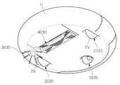
도 1은 본 발명의 제1실시예에 따른 로봇 청소기의 상부 사시도이고, 도 2는 본 발명의 제1실시예에 따른 로봇 청소기의 저부 사시도이고, 도 3은 본 발명의 제1실시예에 따른 로봇 청소기의 단면도이다.1 is a top perspective view of a robot cleaner according to a first embodiment of the present invention, FIG. 2 is a bottom perspective view of a robot cleaner according to a first embodiment of the present invention, and FIG. 3 is a first perspective view of the robot cleaner according to a first embodiment of the present invention. It is a cross section of the robot cleaner.
도 1 내지 도 3에 도시된 바와 같이, 로봇 청소기(1)는 본체(10), 구동장치(20), 클리닝장치(30)와 제어부(미도시)를 포함하여 구성될 수 있다. 구동장치(20)는 본체(10)에 장착되어 로봇 청소기(1)를 주행시키는 메커니즘이다. 클리닝장치(30)는 본체(10)에 장착되어 로봇 청소기(1)의 바닥 및 그 주변을 청소하는 메커니즘이다. 제어부는 센서 또는 시퀀스 등의 신호에 기초하여 로봇 청소기(1)의 구성요소에 명령을 제공함으로서 로봇 청소기(1)가 자동으로 청소할 수 있도록 한다.As illustrated in FIGS. 1 to 3, the
본체(10)에는 로봇 청소기(1)의 구성요소가 설치된다. 즉 본체(10)에는 구동장치(20) 및 클리닝장치(30)와 더불어 장애물을 감지할 수 있는 접촉센서와 근접센서 등이 설치될 수 있다. 예를 들면 본체(10)의 전방에 설치되는 범퍼(11)는 벽 등의 장애물을 감지하는데 사용될 수 있고, 본체(10)의 바닥에 설치되는 적외선 센서(또는 초음파센서)는 계단 등의 장애물을 감지하는데 사용될 수 있다. 또한 본체(10)는 디스플레이장치(12)를 더 포함하도록 구성됨으로써 사용자에게 로봇 청소기(1)의 상태 또는 동작에 관한 정보를 알려 주는 것도 가능하다.The
구동장치(20)는 좌측 구동 휠 어셈블리(21), 우측 구동 휠 어셈블리(22)와 캐스터 휠 어셈블리(23)를 포함하여 구성될 수 있다. 좌우 구동 휠 어셈블리(21, 22)와 캐스터 휠 어셈블리(23)는 본체(10)에 결합되어 로봇 청소기(1)를 지지하면서 로봇 청소기(1)를 주행시킨다. 제어부는 구동장치(20)에 명령을 제공하여 좌우 휠(21a, 22a)을 전방 또는 후방으로 구동시켜 로봇 청소기(1)를 진행방향을 변경할 수 있다. 예를 들면 좌우 휠(21a, 22a) 각각을 동일한 속도로 전방 또는 후방으로 구동시켜 로봇 청소기(1)가 전방으로 이동하도록 한다. 또한 좌우 휠(21a, 22a) 각각의 속도를 다르게 하여 로봇 청소기(1)의 진행 방향을 기준으로 좌측 또는 우측 방향으로 회전하도록 하거나, 제자리에서 회전하도록 한다.The
클리닝장치(30)는 메인 클리닝 어셈블리(40)와 에지 클리닝 어셈블리(50)를 포함하여 구성될 수 있다. 메인 클리닝 어셈블리(40)는 본체(10)의 저부에 설치되어 로봇 청소기(1)가 바닥을 청소하도록 하고, 에지 클리닝 어셈블리(50)는 본체(10)의 일측에 설치되어 로봇 청소기(1)가 그 주변을 청소하도록 한다. 특히 에지 클리닝 어셈블리(50)는 로봇 청소기(1)의 주변에 있는 먼지 또는 잔해물을 로봇 청소기(1)의 진행 경로로 이동시키고, 이후 메인 클리닝 어셈블리(40)는 로봇 청소기(1)가 진행 경로를 따라 이동하는 동안 바닥에 존재하는 먼지 또는 잔해물을 청소한다.The
메인 클리닝 어셈블리(40)는 브러시유닛(60), 송풍유닛(70)과 집진유닛(80)을 포함하여 구성될 수 있다. 브러시유닛(60)과 송풍유닛(70)는 상호 보완하면서 먼지 또는 잔해물을 청소하도록 구성된다. 브러시유닛(60)은 상대적으로 큰 먼지 또는 잔해물을 집진유닛(80)에 쓸어 담고, 송풍유닛(70)은 상대적으로 작은 먼지 또는 잔해물을 집진유닛(80)으로 이동시킨다. 특히 송풍유닛(70)은 브러시유닛(60)에 의해서 비산되는 먼지 또는 잔해물을 흡입한 후 집진유닛(80)으로 송풍한다. 집진유닛(80)은 브러시유닛(60)과 송풍유닛(70)에 의해서 집진유닛(80)으로 이동하는 먼지 또는 잔해물을 저장한다.The
브러시유닛(60)은 본체(10)에 회전 가능하게 설치된다. 본체(10)의 드럼케이스(15)는 브러시유닛(60)을 감싸는 구조로 형성된다. 드럼케이스(15)에 감싸여진 브러시유닛(60)은 모터(미도시), 롤러(61), 브러시(62)와 플랩(63)을 포함하여 구성될 수 있다. 롤러(61)는 강체로 형성되며 본체(10)에 회전 가능하게 결합하고 모터에 의해서 구동된다. 브러시(62)는 탄성 재질로 형성되며 롤러(61)에 심어져 있는 구조이다. 플랩(63)은 탄성 재질로 형성되며 롤러(61)의 길이 방향으로 설치된다. 복수 개의 플랩(63)은 서로 일정 간격 떨어져서 설치된다. 복수 개의 플랩(63)은 머리카락 등 이물질이 감길 수 있는 직경을 크게 하고, 이물질과의 마찰력을 최소화한다. 즉 이물질이 롤러(61)에 직접 감기지 않고 복수 개의 플랩(63)에 감기게 되어 이물질의 접촉 마찰력을 최소화하고, 이물질을 제거하는데 필요한 에너지를 줄일 수 있다.The
로봇 청소기(1)가 주행하는 동안 브러시(62)는 롤러(61)와 함께 구동하면서 바닥에 쌓인 먼지 또는 잔해물을 휘젓게 된다. 이때 상대적으로 큰 먼지 또는 잔해물은 로봇 청소기(1)의 진행방향의 후방으로 이동하여 먼지통(81)의 제1유입구(83a)를 통하여 제1저장공간(83)에 저장된다. 이와 더불어 브러시유닛(60)에 의해서 휘저어진 작은 먼지 또는 잔해물은 브러시유닛(60)과 드럼케이스(15) 사이로 비산되는데, 이들 먼지들은 송풍유닛(70)에 의해서 로봇 청소기(1)의 진행방향의 전방으로 이동한 후 다시 로봇 청소기(1)의 진행방향의 후방으로 이동하여 먼지통(81)의 제2유입구(84a)를 통하여 제2저장공간(84)에 저장된다.While the
송풍유닛(70)은 본체(10)의 전방에 설치된다. 송풍유닛(70)은 팬(71), 흡입유로(72), 흡입구(72a), 배기유로(73)와 배기구(73a)를 포함하여 구성될 수 있다. 팬(71)은 모터(미도시)에 의해서 구동되고, 바이패스 임펠러(bypass impeller)가 사용될 수 있다. 팬(71)은 흡입유로(72)와 배기유로(73) 사이에 배치되고, 흡입유로(72)는 브러시유닛(60)의 반경 방향으로 형성되어(또는 본체(10)의 후방에서 전방으로 형성되어) 브러시유닛(60)과 팬(71)을 연결하고, 배기유로(73)는 본체(10)의 전방에서 후방으로 형성되어 팬(71)과 먼지통(81)을 연결하도록 배치된다. 흡입구(72a)는 드럼케이스(15)에 형성되어 브러시유닛(60)과 드럼케이스(15) 사이에서 비산되는 먼지 또는 잔해물을 흡입유로(72)로 이동시키는 입구 역할을 한다. 배기구(73a)는 제2유입구(84a)와 맞물려서 배기유로(73)에서 이동되는 먼지 또는 잔해물을 제2저장공간(84)으로 이동시키는 출구 역할을 한다.The blowing
집진유닛(80)은 본체(10)의 후방에 설치된다. 집진유닛(80)은 송풍유닛(70)과 별개로 본체(10)에 착탈 가능하게 설치된다. 사용자는 집진유닛(80)을 본체(10)로부터 분리하여 집진유닛(80)을 물로 세척하거나, 그 내부에 저장된 먼지를 비우는 것이 가능하다. 집진유닛(80)은 송풍유닛(70)과 분리되어 집진유닛(80)에는 전자부품이 설치되지 않기 때문에 집진유닛(80)을 물로 세척하여도 집진유닛(80)이 고장날 우려가 없다.The
도 4는 본 발명의 제1실시예에 따른 집진유닛의 사시도이다.4 is a perspective view of a dust collecting unit according to a first embodiment of the present invention.
도 1 내지 도 4를 도시된 바와 같이, 집진유닛(80)은 먼지통(81), 필터부재(86), 커버(89)와 연결구멍(87)을 포함하여 구성될 수 있다.1 to 4, the
먼지통(81)은 본체(10)에 착탈됨과 동시에 본체(10)의 외벽을 형성한다. 먼지통(81) 내부는 격벽(82)에 의해서 제1저장공간(83)과 제2저장공간(84)으로 구획된다. 제1저장공간(83)은 상대적으로 큰 먼지 또는 잔해물을 저장하는 공간이고, 제2저장공간(84)은 상대적으로 작은 먼지 또는 잔해물, 즉 미세먼지를 저장하는 공간이다. 제1저장공간(83)은 제2저장공간(84)의 하측에 배치되고, 제1저장공간(83)이 제2저장공간(84)보다 부피가 크게 형성된다. 제1저장공간(83)은 제1유입구(83a)와 연통되어 있어서, 브러시유닛(60)이 휘젓는 먼지 또는 잔해물을 저장하는 것이 가능하다. 제2저장공간(84)은 제2유입구(84a)와 연통되어 있어서, 브러시유닛(60)에 의해서 비산되고 송풍유닛(70)이 송풍하는 먼지 또는 잔해물을 저장하는 것이 가능하다.The
먼지통(81)은 제2저장공간(84)이 송풍유닛(70)과 연통되기 때문에 송풍유닛(70)에서 배기되는 공기를 밖으로 내보내기 위하여 그 상부에 배출구(85)를 구비한다. 배출구(85)에는 필터부재(86)가 설치되어 배출구(85)를 통과하는 공기는 정화되어 밖으로 배출된다. 흡입구(72a)를 통하여 흡입되는 미세먼지는 송풍유닛(70)의 팬(71)을 거친 후 집진유닛(80)의 필터부재(86)를 통과하여 밖으로 배출된다.The
연결구멍(87)은 먼지통(81)의 상부에 형성된다. 연결구멍(87)은 제1저장공 간(83) 및 제2저장공간(84)과 연통한다. 제1저장공간(83)과 제2저장공간(84)을 구획하는 격벽(82)은 연결구멍(87)의 하측에 배치되기 때문이다. 사용자는 별도의 먼지제거장치(90)(도 7 참조)를 연결구멍(87)을 통하여 먼지통(81)과 연결하고, 진공흡입력을 이용하여 자동으로 먼지통(81)의 저장된 먼지 또는 잔해물을 제거할 수 있다. 연결구멍(87)을 사용하지 않는 경우 연결구멍(87)에는 캡(88)이 설치되어 먼지 또는 잔해물이 밖으로 빠져나가지 않도록 한다.The
한편, 커버(89)는 제2저장공간(84)을 개폐하도록 먼지통(81)에 설치된다. 먼지통(81)에 본체(10)에 장착되어 있는 경우 커버(89)는 제2저장공간(84)을 밀폐시킨다. 이때 커버(89)에 마련되는 제2유입구(84a)를 통하여, 먼지 또는 잔해물이 제2저장공간(84)으로 유입될 수 있다. 다만 사용자가 먼지를 비우기 위하여 먼지통(81)을 본체(10)로부터 분리하는 경우 커버(89)는 제2저장공간(84)을 개방하여 사용자가 쉽게 먼지통(81)에 저장된 먼지를 비울 수 있도록 한다. 제1저장공간(83)에 저장된 먼지 또는 잔해물은 제1유입구(83a)를 통하여 쉽게 비울 수 있고, 제2저장공간(84)에 저장된 먼지 또는 잔해물은 커버(89)를 개방하여 쉽게 비울 수 있다. On the other hand, the
도 5는 본 발명의 제1실시예에 따른 로봇 청소기의 청소 모습을 나타낸 도면이다.5 is a view showing a cleaning state of the robot cleaner according to the first embodiment of the present invention.
도 1 내지 도 5에 도시된 바와 같이, 로봇 청소기(1)는 바닥을 주행하면서 먼지 또는 잔해물을 청소한다. 브러시유닛(60)은 상대적으로 큰 먼지 또는 잔해물을 쓸어 담고, 송풍유닛(70)은 상대적으로 작은 미세 먼지를 흡입한다. 브러시(62)가 바닥을 쓸어 내는 경우 먼지 또는 잔해물은 제1유입구(83a)를 통하여 제1저장공 간(83)에 저장되고, 브러시(62)에 의해서 비산되는 먼지 또는 잔해물은 팬(71)에 의해서 흡입구(72a)로 흡입된 후 제2유입구(84a)를 통하여 제2저장공간(84)에 저장된다.As shown in FIGS. 1 to 5, the
한편, 제2저장공간(84)은 배출구(85)를 통하여 외부와 연통되는데, 배출구(85)에는 필터부재(86)가 설치되어 제2저장공간(84)에 저장되는 먼지 또는 잔해물이 밖으로 빠져나가지 않도록 하고, 필터부재(86)를 통과하는 공기는 정화되어 밖으로 빠져나간다. 팬(71)은 브러시(62)에 의해서 비산되는 미세 먼지를 흡입하기 때문에 팬(71)이 큰 이물질에 걸리거나 고장날 우려가 없고, 필터부재(86)는 팬(71)과 이격되어 먼지통(81)에 설치되기 때문에 필터부재(86)가 팬(71)의 성능에 직접적인 영향을 줄 수 없다. 이처럼 팬(71)의 성능을 확보하여 청소 효율을 높일 수 있고, 미세 먼지를 흡입하는 것이므로 저전력으로 팬(71)을 구동하는 경우에도 청소 효율을 높게 유지할 수 있다.On the other hand, the
도 6은 본 발명의 제1실시예에 따른 먼지통을 수동으로 비우는 모습을 나타낸 도면이다.6 is a view showing a state of emptying the dust container manually according to the first embodiment of the present invention.
도 1 내지 도 6에 도시된 바와 같이, 로봇 청소기(1)가 청소를 완료하거나 먼지통(81)이 가득 찬 경우에는 먼지통(81)에 저장된 먼지 또는 잔해물을 제거한다. 사용자는 먼지통(81)을 본체(10)로부터 분리하여 제1저장공간(83)에 저장된 먼지 또는 잔해물을 제1유입구(83a)를 통하여 제거하고, 커버(89)를 개방한 후 제2저장공간(84)에 저장된 먼지 또는 잔해물을 제거한다. 팬(71)은 먼지통(81)으로부터 분리되어 있기 때문에 사용자는 먼지통(81)을 물로 세척하는 것이 가능하다.As shown in FIGS. 1 to 6, when the
도 7은 본 발명의 제1실시예에 따른 먼지통을 자동으로 비우는 모습을 나타낸 도면이다.7 is a view showing the appearance of emptying the dust container according to the first embodiment of the present invention automatically.
도 1 내지 도 7에 도시된 바와 같이, 로봇 청소기(1)가 청소를 완료하거나 먼지통(81)이 가득 찬 경우에는 먼지통(81)에 저장된 먼지 또는 잔해물을 제거한다. 사용자는 캡(88)을 제거한 후 별도의 먼지제거장치(90)를 연결구멍(87)과 연결시키고, 먼지제거장치(90)의 흡입력을 이용하여 먼지통(81)에 저장된 먼지 또는 잔해물을 제거한다. 이때 연결구멍(87)은 제1저장공간(83) 및 제2저장공간(84)과 모두 연통하기 때문에 먼지제거장치(90)는 먼지통(81)에 저장된 먼지 또는 잔해물을 전부 제거할 수 있다.As shown in FIGS. 1 to 7, when the
도 1은 본 발명의 일 실시예에 따른 로봇 청소기의 상부 사시도이다.1 is a top perspective view of a robot cleaner according to an embodiment of the present invention.
도 2는 본 발명의 일 실시예에 따른 로봇 청소기의 저부 사시도이다.2 is a bottom perspective view of a robot cleaner according to an embodiment of the present invention.
도 3은 본 발명의 일 실시예에 따른 로봇 청소기의 단면도이다.3 is a cross-sectional view of the robot cleaner according to an embodiment of the present invention.
도 4는 본 발명의 일 실시예에 따른 집진유닛의 사시도이다.4 is a perspective view of a dust collecting unit according to an embodiment of the present invention.
도 5는 본 발명의 실시예에 따른 로봇 청소기의 청소 모습을 나타낸 도면이다.5 is a view showing a cleaning state of the robot cleaner according to an embodiment of the present invention.
도 6은 본 발명의 실시예에 따른 먼지통을 수동으로 비우는 모습을 나타낸 도면이다.6 is a view showing a state of emptying the dust bin manually according to an embodiment of the present invention.
도 7은 본 발명의 실시예에 따른 먼지통을 자동으로 비우는 모습을 나타낸 도면이다.7 is a view showing a state of emptying the dust container automatically according to an embodiment of the present invention.
* 도면의 주요부분에 대한 부호의 설명 * Explanation of symbols on the main parts of the drawings
1: 로봇 청소기 10: 본체1: robot cleaner 10: main unit
20: 구동장치 30: 클리닝장치20: drive device 30: cleaning device
40: 메인 클리닝 어셈블리 50: 에지 클리닝 어셈블리40: main cleaning assembly 50: edge cleaning assembly
60: 브러시유닛 70: 송풍유닛60: brush unit 70: blowing unit
80: 집진유닛80: dust collecting unit
Claims (19)
Translated fromKoreanPriority Applications (4)
| Application Number | Priority Date | Filing Date | Title |
|---|---|---|---|
| US12/786,766US8505158B2 (en) | 2009-06-10 | 2010-05-25 | Cleaning apparatus and dust collecting method using the same |
| CN201080026226.9ACN102481080B (en) | 2009-06-10 | 2010-06-10 | Cleaning apparatus and dust collecting method using the same |
| EP10786373.0AEP2440100B1 (en) | 2009-06-10 | 2010-06-10 | Cleaning apparatus and dust collecting method using the same |
| PCT/KR2010/003708WO2010143890A2 (en) | 2009-06-10 | 2010-06-10 | Cleaning apparatus and dust collecting method using the same |
Applications Claiming Priority (2)
| Application Number | Priority Date | Filing Date | Title |
|---|---|---|---|
| US18561809P | 2009-06-10 | 2009-06-10 | |
| US61/185,618 | 2009-06-10 |
Publications (1)
| Publication Number | Publication Date |
|---|---|
| KR20100132891Atrue KR20100132891A (en) | 2010-12-20 |
Family
ID=43508431
Family Applications (2)
| Application Number | Title | Priority Date | Filing Date |
|---|---|---|---|
| KR1020090058434ACeasedKR20100132891A (en) | 2009-06-10 | 2009-06-29 | Cleaning device and dust collection method using the same |
| KR1020090062246ACeasedKR20100132893A (en) | 2009-06-10 | 2009-07-08 | Cleaning device and dust collection method using the same |
Family Applications After (1)
| Application Number | Title | Priority Date | Filing Date |
|---|---|---|---|
| KR1020090062246ACeasedKR20100132893A (en) | 2009-06-10 | 2009-07-08 | Cleaning device and dust collection method using the same |
Country Status (5)
| Country | Link |
|---|---|
| US (1) | US8505158B2 (en) |
| EP (1) | EP2440100B1 (en) |
| KR (2) | KR20100132891A (en) |
| CN (1) | CN102481080B (en) |
| WO (1) | WO2010143890A2 (en) |
Cited By (1)
| Publication number | Priority date | Publication date | Assignee | Title |
|---|---|---|---|---|
| KR101323216B1 (en)* | 2011-12-26 | 2013-10-30 | 엘아이지에이디피 주식회사 | Apparatus and method for cleaning of gas distribution unit |
Families Citing this family (98)
| Publication number | Priority date | Publication date | Assignee | Title |
|---|---|---|---|---|
| EP2816434A3 (en)* | 2005-12-02 | 2015-01-28 | iRobot Corporation | Autonomous coverage robot |
| EP2273906B1 (en) | 2008-03-17 | 2018-11-14 | Electrolux Home Care Products, Inc. | Agitator with cleaning features |
| US9295362B2 (en) | 2008-03-17 | 2016-03-29 | Aktiebolaget Electrolux | Vacuum cleaner agitator cleaner with power control |
| US9820626B2 (en) | 2008-03-17 | 2017-11-21 | Aktiebolaget Electrolux | Actuator mechanism for a brushroll cleaner |
| US10117553B2 (en) | 2008-03-17 | 2018-11-06 | Aktiebolaget Electrolux | Cleaning nozzle for a vacuum cleaner |
| US9572465B2 (en) | 2008-12-08 | 2017-02-21 | Emerson Electric Co. | Slide out drum with filter for a wet/dry vacuum appliance |
| US8973196B2 (en)* | 2008-12-08 | 2015-03-10 | Emerson Electric Co. | Slide-out drum with filter for a wet/dry vacuum appliance |
| DE102009034955B4 (en) | 2009-07-28 | 2023-06-15 | Vorwerk & Co. Interholding Gmbh | Automatically movable floor dust collector |
| TWM407725U (en)* | 2010-12-20 | 2011-07-21 | Micro Star Internat Corp Ltd | Dust collecting container and vacuum cleaner applying the same |
| US8741013B2 (en)* | 2010-12-30 | 2014-06-03 | Irobot Corporation | Dust bin for a robotic vacuum |
| ITMI20111654A1 (en)* | 2011-09-14 | 2013-03-15 | Antil S P A | ROBOTIC DEVICE FOR SURFACE TREATMENT OF ROLLS FOR METALLIC MANUFACTURING |
| EP2770892B1 (en) | 2011-10-26 | 2015-09-23 | Aktiebolaget Electrolux | Cleaning nozzle for a vacuum cleaner |
| JP6012181B2 (en)* | 2012-01-13 | 2016-10-25 | シャープ株式会社 | Dust collector and self-propelled cleaner provided with the dust collector [7] |
| US9993847B2 (en) | 2012-02-02 | 2018-06-12 | Aktiebolaget Electrolux | Cleaning arrangement for a nozzle of a vacuum cleaner |
| KR101476206B1 (en)* | 2012-05-24 | 2014-12-24 | 엘지전자 주식회사 | A robot cleaner |
| ES2610755T3 (en) | 2012-08-27 | 2017-05-03 | Aktiebolaget Electrolux | Robot positioning system |
| KR102075186B1 (en) | 2012-12-21 | 2020-02-07 | 악티에볼라겟 엘렉트로룩스 | Cleaning arrangement for a rotatable member of a vacuum cleaner, cleaner nozzle, vacuum cleaner and cleaning unit |
| US9072416B2 (en) | 2013-03-15 | 2015-07-07 | Aktiebolaget Electrolux | Vacuum cleaner agitator cleaner with brushroll lifting mechanism |
| KR102137923B1 (en) | 2013-04-15 | 2020-07-24 | 에이비 엘렉트로룩스 | Robotic vacuum cleaner with protruding sidebrush |
| WO2014169943A1 (en) | 2013-04-15 | 2014-10-23 | Aktiebolaget Electrolux | Robotic vacuum cleaner |
| CN105392406B (en) | 2013-05-02 | 2018-04-27 | 伊莱克斯公司 | Cleaning nozzles for vacuum cleaners |
| DE102014112313A1 (en)* | 2013-08-30 | 2015-03-05 | Wessel-Werk Gmbh | Self-propelled vacuum cleaning device |
| JP2017503267A (en) | 2013-12-18 | 2017-01-26 | アイロボット コーポレイション | Autonomous mobile robot |
| KR102116596B1 (en) | 2013-12-19 | 2020-05-28 | 에이비 엘렉트로룩스 | Robotic vacuum cleaner with side brush moving in spiral pattern |
| US10433697B2 (en) | 2013-12-19 | 2019-10-08 | Aktiebolaget Electrolux | Adaptive speed control of rotating side brush |
| US10617271B2 (en) | 2013-12-19 | 2020-04-14 | Aktiebolaget Electrolux | Robotic cleaning device and method for landmark recognition |
| US10209080B2 (en) | 2013-12-19 | 2019-02-19 | Aktiebolaget Electrolux | Robotic cleaning device |
| CN105829985B (en) | 2013-12-19 | 2020-04-07 | 伊莱克斯公司 | Robot cleaning device with peripheral recording function |
| CN105793790B (en) | 2013-12-19 | 2022-03-04 | 伊莱克斯公司 | Prioritize cleaning areas |
| WO2015090405A1 (en) | 2013-12-19 | 2015-06-25 | Aktiebolaget Electrolux | Sensing climb of obstacle of a robotic cleaning device |
| WO2015090439A1 (en) | 2013-12-20 | 2015-06-25 | Aktiebolaget Electrolux | Dust container |
| CN104771116B (en)* | 2014-01-14 | 2017-08-25 | 莱克电气绿能科技(苏州)有限公司 | Floor brush of dust collector and dust catcher with major-minor air channel |
| DE102015101587B3 (en)* | 2014-05-30 | 2015-07-09 | Wessel-Werk Gmbh | Robotsauger with multiple arrangement of side brushes |
| CN106415423B (en) | 2014-07-10 | 2021-01-01 | 伊莱克斯公司 | Method for detecting a measurement error of a robotic cleaning device |
| US10499778B2 (en) | 2014-09-08 | 2019-12-10 | Aktiebolaget Electrolux | Robotic vacuum cleaner |
| EP3190938A1 (en) | 2014-09-08 | 2017-07-19 | Aktiebolaget Electrolux | Robotic vacuum cleaner |
| US11064856B1 (en) | 2014-10-21 | 2021-07-20 | AI Incorporated | Detachable robotic vacuum dustbin |
| EP3230814B1 (en) | 2014-12-10 | 2021-02-17 | Aktiebolaget Electrolux | Using laser sensor for floor type detection |
| CN107072454A (en) | 2014-12-12 | 2017-08-18 | 伊莱克斯公司 | Side brushes and robot vacuums |
| EP3234713B1 (en) | 2014-12-16 | 2022-06-15 | Aktiebolaget Electrolux | Cleaning method for a robotic cleaning device |
| CN107003669B (en) | 2014-12-16 | 2023-01-31 | 伊莱克斯公司 | Experience-Based Roadmap for Robotic Cleaning Equipment |
| US11099554B2 (en) | 2015-04-17 | 2021-08-24 | Aktiebolaget Electrolux | Robotic cleaning device and a method of controlling the robotic cleaning device |
| JP5965513B2 (en)* | 2015-05-08 | 2016-08-03 | シャープ株式会社 | Self-propelled vacuum cleaner |
| JP6496612B2 (en)* | 2015-06-05 | 2019-04-03 | 株式会社マキタ | Self-propelled dust collection robot |
| DE102015110140A1 (en)* | 2015-06-24 | 2016-12-29 | Vorwerk & Co. Interholding Gmbh | Support of a surface cleaning |
| EP3344104B1 (en) | 2015-09-03 | 2020-12-30 | Aktiebolaget Electrolux | System of robotic cleaning devices |
| JP5933090B2 (en)* | 2015-10-09 | 2016-06-08 | シャープ株式会社 | Dust collector and self-propelled vacuum cleaner provided with the same |
| JP5926849B2 (en)* | 2015-11-20 | 2016-05-25 | シャープ株式会社 | Dust collector and self-propelled vacuum cleaner provided with the same |
| JP5941591B2 (en)* | 2015-11-20 | 2016-06-29 | シャープ株式会社 | Dust collector and self-propelled vacuum cleaner provided with the same |
| JP5938134B2 (en)* | 2015-11-20 | 2016-06-22 | シャープ株式会社 | Dust collector and self-propelled vacuum cleaner provided with the same |
| JP5894701B2 (en)* | 2015-11-20 | 2016-03-30 | シャープ株式会社 | Dust collector and self-propelled vacuum cleaner provided with the same |
| JP5933100B2 (en)* | 2015-11-20 | 2016-06-08 | シャープ株式会社 | Dust collector and self-propelled vacuum cleaner provided with the same |
| JP5926847B2 (en)* | 2015-11-20 | 2016-05-25 | シャープ株式会社 | Dust collector and self-propelled vacuum cleaner provided with the same |
| JP5957135B2 (en)* | 2015-11-20 | 2016-07-27 | シャープ株式会社 | Dust collector and self-propelled vacuum cleaner provided with the same |
| JP5933096B2 (en)* | 2015-11-20 | 2016-06-08 | シャープ株式会社 | Dust collector and self-propelled vacuum cleaner provided with the same |
| JP5933101B2 (en)* | 2015-11-20 | 2016-06-08 | シャープ株式会社 | Dust collector and self-propelled vacuum cleaner provided with the same |
| JP5933099B2 (en)* | 2015-11-20 | 2016-06-08 | シャープ株式会社 | Dust collector and self-propelled vacuum cleaner provided with the same |
| JP5933098B2 (en)* | 2015-11-20 | 2016-06-08 | シャープ株式会社 | Dust collector and self-propelled vacuum cleaner provided with the same |
| JP5933097B2 (en)* | 2015-11-20 | 2016-06-08 | シャープ株式会社 | Dust collector and self-propelled vacuum cleaner provided with the same |
| JP5926848B2 (en)* | 2015-11-20 | 2016-05-25 | シャープ株式会社 | Dust collector and self-propelled vacuum cleaner provided with the same |
| JP5933102B2 (en)* | 2015-11-20 | 2016-06-08 | シャープ株式会社 | Dust collector and self-propelled vacuum cleaner provided with the same |
| CN107157409B (en)* | 2016-03-07 | 2019-08-23 | 烟台大学 | A kind of water-saving type flooring cleaning vehicle |
| WO2017157421A1 (en) | 2016-03-15 | 2017-09-21 | Aktiebolaget Electrolux | Robotic cleaning device and a method at the robotic cleaning device of performing cliff detection |
| JP2016106007A (en)* | 2016-03-24 | 2016-06-16 | シャープ株式会社 | Self-propelled vacuum cleaner |
| US11122953B2 (en) | 2016-05-11 | 2021-09-21 | Aktiebolaget Electrolux | Robotic cleaning device |
| DE102016111806A1 (en)* | 2016-06-28 | 2017-12-28 | Vorwerk & Co. Interholding Gmbh | Wet cleaning device with a cleaning roller rotatable about a roll axis |
| WO2018049169A1 (en) | 2016-09-09 | 2018-03-15 | Sharkninja Operating Llc | Agitator with hair removal |
| JP2018068825A (en)* | 2016-11-01 | 2018-05-10 | 三菱電機株式会社 | Self-propelled vacuum cleaner |
| USD808096S1 (en)* | 2016-12-20 | 2018-01-16 | Samsung Electronics Co., Ltd. | Robot cleaner |
| CN208582332U (en) | 2017-01-26 | 2019-03-08 | 深圳洛克时代科技有限公司 | Intelligent cleaning equipment water tank and intelligent cleaning equipment |
| USD870403S1 (en)* | 2017-03-02 | 2019-12-17 | AI Incorporated | Robotic vacuum |
| CN114403741B (en)* | 2017-03-10 | 2024-02-27 | 尚科宁家运营有限公司 | Agitator with a hair remover and hair removal |
| USD872953S1 (en)* | 2017-03-21 | 2020-01-14 | AI Incorporated | Robotic vacuum |
| EP3629866B1 (en) | 2017-05-26 | 2022-01-19 | SharkNinja Operating LLC | Hair cutting brushroll |
| EP3629869B1 (en) | 2017-06-02 | 2023-08-16 | Aktiebolaget Electrolux | Method of detecting a difference in level of a surface in front of a robotic cleaning device |
| KR102000068B1 (en) | 2017-08-07 | 2019-07-15 | 엘지전자 주식회사 | Cleaner |
| KR102033936B1 (en) | 2017-08-07 | 2019-10-18 | 엘지전자 주식회사 | Robot Cleaner |
| KR102021828B1 (en) | 2017-08-07 | 2019-09-17 | 엘지전자 주식회사 | Cleaner |
| KR102014140B1 (en) | 2017-08-07 | 2019-08-26 | 엘지전자 주식회사 | Robot Cleaner |
| CN107322414A (en)* | 2017-08-18 | 2017-11-07 | 浙江湖州天强建筑材料有限公司 | A kind of construction material sander |
| EP3687357B1 (en) | 2017-09-26 | 2024-07-10 | Aktiebolaget Electrolux | Controlling movement of a robotic cleaning device |
| US12426753B2 (en)* | 2017-11-16 | 2025-09-30 | Irobot Corporation | Washable bin for a robot vacuum cleaner |
| WO2019099645A1 (en)* | 2017-11-17 | 2019-05-23 | Milwaukee Electric Tool Corporation | Floor cleaning machine |
| CN107854047A (en)* | 2017-12-13 | 2018-03-30 | 莱克电气股份有限公司 | A kind of ground brush assemblies of surface cleaning apparatus |
| US11672393B2 (en) | 2017-12-27 | 2023-06-13 | Sharkninja Operating Llc | Cleaning apparatus with selectable combing unit for removing debris from cleaning roller |
| CN111787836B (en) | 2017-12-27 | 2022-10-14 | 尚科宁家运营有限公司 | End cap assembly |
| CN108185909A (en)* | 2017-12-29 | 2018-06-22 | 中山市金舜家庭用品有限公司 | A kind of floor cleaner |
| KR102045003B1 (en) | 2018-01-25 | 2019-11-14 | 엘지전자 주식회사 | Controlling Method of Robot Cleaner |
| US11503968B2 (en)* | 2018-08-10 | 2022-11-22 | Sharkninja Operating Llc | System and method for reducing noise and/or vibration in a cleaning apparatus with combing unit for removing debris |
| USD920493S1 (en)* | 2019-05-07 | 2021-05-25 | Matthew Aaron Alexander | Essential oil diffuser |
| CN114375171A (en)* | 2019-09-04 | 2022-04-19 | 伊莱克斯公司 | Brush roll of vacuum cleaner |
| DE102020115219A1 (en)* | 2020-06-09 | 2021-12-09 | Miele & Cie. Kg | Vacuum robot |
| CN112120590B (en)* | 2020-09-29 | 2022-02-11 | 苏州云森科技有限公司 | Floor cleaner with multifunctional dust box cover |
| USD973988S1 (en)* | 2020-10-21 | 2022-12-27 | Shenzhen Dimengyuan Technology Co., Ltd. | Vacuum cleaner |
| CN115429153A (en)* | 2021-06-02 | 2022-12-06 | 南京西新人工智能研究院有限公司 | Household cleaning and sweeping robot with self-learning capability |
| WO2023278541A1 (en)* | 2021-06-29 | 2023-01-05 | Sharkninja Operating Llc | Robotic cleaner |
| TWD222441S (en)* | 2022-01-05 | 2022-12-01 | 大陸商北京石頭世紀科技股份有限公司 | Dust box |
| CN119855529A (en)* | 2022-11-14 | 2025-04-18 | 三星电子株式会社 | Cleaning apparatus |
Family Cites Families (20)
| Publication number | Priority date | Publication date | Assignee | Title |
|---|---|---|---|---|
| US2701377A (en)* | 1949-01-17 | 1955-02-08 | Tennant Co G H | Rotary brush power sweeper |
| SE370616B (en)* | 1972-12-15 | 1974-10-28 | Electrolux Ab | |
| US4206530A (en)* | 1978-01-30 | 1980-06-10 | Tennant Company | Surface maintenance machine having air recirculation |
| US5018240A (en)* | 1990-04-27 | 1991-05-28 | Cimex Limited | Carpet cleaner |
| JP3188116B2 (en)* | 1994-09-26 | 2001-07-16 | 日本輸送機株式会社 | Self-propelled vacuum cleaner |
| JP3641618B2 (en)* | 2002-05-02 | 2005-04-27 | 山崎産業株式会社 | Cleaning tool |
| JP2005102892A (en) | 2003-09-30 | 2005-04-21 | Sanyo Electric Co Ltd | Upright vacuum cleaner |
| GB0326311D0 (en) | 2003-11-12 | 2003-12-17 | Grey Technology Ltd | Surface cleaning apparatus |
| CN100361615C (en)* | 2004-03-18 | 2008-01-16 | 泰怡凯电器(苏州)有限公司 | Automatic suction cleaner |
| KR100711972B1 (en) | 2004-12-08 | 2007-05-02 | 주식회사 유진로봇 | Cleaning robot and its cleaning method |
| KR100588061B1 (en)* | 2004-12-22 | 2006-06-09 | 주식회사유진로보틱스 | Cleaning Robot with Double Suction |
| KR100697080B1 (en) | 2005-03-30 | 2007-03-20 | 엘지전자 주식회사 | Wet and Dry Upright Cleaner |
| KR100738890B1 (en)* | 2005-07-22 | 2007-07-12 | 엘지전자 주식회사 | Home Networking System using Mobile Robot |
| JP4342526B2 (en)* | 2006-03-14 | 2009-10-14 | 株式会社東芝 | Electric vacuum cleaner |
| US20090044370A1 (en)* | 2006-05-19 | 2009-02-19 | Irobot Corporation | Removing debris from cleaning robots |
| JP2006312066A (en) | 2006-07-11 | 2006-11-16 | Mitsubishi Electric Corp | Electric vacuum cleaner |
| KR101204440B1 (en)* | 2007-02-26 | 2012-11-26 | 삼성전자주식회사 | Robot cleaner system having robot cleaner and docking station |
| EP1980188B1 (en)* | 2007-03-27 | 2012-11-14 | Samsung Electronics Co., Ltd. | Robot cleaner with improved dust collector |
| KR20090034493A (en)* | 2007-10-04 | 2009-04-08 | 삼성전자주식회사 | robotic vacuum |
| KR101330735B1 (en)* | 2007-10-17 | 2013-11-20 | 삼성전자주식회사 | Robot cleaner |
- 2009
- 2009-06-29KRKR1020090058434Apatent/KR20100132891A/ennot_activeCeased
- 2009-07-08KRKR1020090062246Apatent/KR20100132893A/ennot_activeCeased
- 2010
- 2010-05-25USUS12/786,766patent/US8505158B2/enactiveActive
- 2010-06-10WOPCT/KR2010/003708patent/WO2010143890A2/ennot_activeCeased
- 2010-06-10CNCN201080026226.9Apatent/CN102481080B/enactiveActive
- 2010-06-10EPEP10786373.0Apatent/EP2440100B1/enactiveActive
Cited By (1)
| Publication number | Priority date | Publication date | Assignee | Title |
|---|---|---|---|---|
| KR101323216B1 (en)* | 2011-12-26 | 2013-10-30 | 엘아이지에이디피 주식회사 | Apparatus and method for cleaning of gas distribution unit |
Also Published As
| Publication number | Publication date |
|---|---|
| US8505158B2 (en) | 2013-08-13 |
| CN102481080B (en) | 2014-12-24 |
| EP2440100A4 (en) | 2016-06-01 |
| KR20100132893A (en) | 2010-12-20 |
| US20100313912A1 (en) | 2010-12-16 |
| WO2010143890A2 (en) | 2010-12-16 |
| CN102481080A (en) | 2012-05-30 |
| EP2440100A2 (en) | 2012-04-18 |
| EP2440100B1 (en) | 2017-11-01 |
| WO2010143890A3 (en) | 2011-03-31 |
Similar Documents
| Publication | Publication Date | Title |
|---|---|---|
| KR20100132891A (en) | Cleaning device and dust collection method using the same | |
| CN107313376B (en) | An all-in-one machine for vacuuming, washing and drying | |
| US20220022709A1 (en) | Autonomous vacuum | |
| CN101273860B (en) | Robot cleaner with improved dust collector | |
| EP2654539B1 (en) | Vacuum cleaner | |
| JP2012024625A (en) | Household robotic vacuum cleaner | |
| KR101556965B1 (en) | Vacuum cleaner nozzle assembly | |
| KR102325528B1 (en) | Robot Cleaner | |
| KR20090034493A (en) | robotic vacuum | |
| KR101052182B1 (en) | Corner cleaning device and cleaner having same | |
| JP2018061535A (en) | Self-travelling vacuum cleaner | |
| KR101012943B1 (en) | Suction unit for indoor corner cleaning | |
| JP6105886B2 (en) | Suction port and vacuum cleaner | |
| JP2019050968A (en) | Self-propelled robot vacuum cleaner | |
| KR20090129114A (en) | vacuum cleaner | |
| JP2017104335A (en) | Vacuum cleaner | |
| KR101292537B1 (en) | Robot cleaner | |
| CN117677329A (en) | Dust collector station | |
| KR20070115224A (en) | Vacuum cleaner | |
| KR101330729B1 (en) | Robot cleaner | |
| JP6640603B2 (en) | Self-propelled vacuum cleaner | |
| CN219089114U (en) | Floor brush structure and cleaning equipment | |
| CN116392045B (en) | Floor brush structure and cleaning equipment | |
| KR102570849B1 (en) | Cleaning apparatus for viehicle | |
| KR101043535B1 (en) | Auto cleaner |
Legal Events
| Date | Code | Title | Description |
|---|---|---|---|
| PA0109 | Patent application | Patent event code:PA01091R01D Comment text:Patent Application Patent event date:20090629 | |
| PG1501 | Laying open of application | ||
| N231 | Notification of change of applicant | ||
| PN2301 | Change of applicant | Patent event date:20110314 Comment text:Notification of Change of Applicant Patent event code:PN23011R01D | |
| A201 | Request for examination | ||
| PA0201 | Request for examination | Patent event code:PA02012R01D Patent event date:20140619 Comment text:Request for Examination of Application Patent event code:PA02011R01I Patent event date:20090629 Comment text:Patent Application | |
| E902 | Notification of reason for refusal | ||
| PE0902 | Notice of grounds for rejection | Comment text:Notification of reason for refusal Patent event date:20150618 Patent event code:PE09021S01D | |
| AMND | Amendment | ||
| E601 | Decision to refuse application | ||
| PE0601 | Decision on rejection of patent | Patent event date:20160127 Comment text:Decision to Refuse Application Patent event code:PE06012S01D Patent event date:20150618 Comment text:Notification of reason for refusal Patent event code:PE06011S01I | |
| AMND | Amendment | ||
| J201 | Request for trial against refusal decision | ||
| PJ0201 | Trial against decision of rejection | Patent event date:20160226 Comment text:Request for Trial against Decision on Refusal Patent event code:PJ02012R01D Patent event date:20160127 Comment text:Decision to Refuse Application Patent event code:PJ02011S01I Appeal kind category:Appeal against decision to decline refusal Appeal identifier:2016101001170 Request date:20160226 | |
| PB0901 | Examination by re-examination before a trial | Comment text:Amendment to Specification, etc. Patent event date:20160226 Patent event code:PB09011R02I Comment text:Request for Trial against Decision on Refusal Patent event date:20160226 Patent event code:PB09011R01I Comment text:Amendment to Specification, etc. Patent event date:20150819 Patent event code:PB09011R02I | |
| B601 | Maintenance of original decision after re-examination before a trial | ||
| PB0601 | Maintenance of original decision after re-examination before a trial | ||
| J301 | Trial decision | Free format text:TRIAL NUMBER: 2016101001170; TRIAL DECISION FOR APPEAL AGAINST DECISION TO DECLINE REFUSAL REQUESTED 20160226 Effective date:20161031 | |
| PJ1301 | Trial decision | Patent event code:PJ13011S01D Patent event date:20161031 Comment text:Trial Decision on Objection to Decision on Refusal Appeal kind category:Appeal against decision to decline refusal Request date:20160226 Decision date:20161031 Appeal identifier:2016101001170 |