KR20100129015A - Touch detection device, display device and coordinate recognition method comprising the same - Google Patents
Touch detection device, display device and coordinate recognition method comprising the sameDownload PDFInfo
- Publication number
- KR20100129015A KR20100129015AKR1020090047745AKR20090047745AKR20100129015AKR 20100129015 AKR20100129015 AKR 20100129015AKR 1020090047745 AKR1020090047745 AKR 1020090047745AKR 20090047745 AKR20090047745 AKR 20090047745AKR 20100129015 AKR20100129015 AKR 20100129015A
- Authority
- KR
- South Korea
- Prior art keywords
- reflection
- detectors
- laser
- display unit
- detected
- Prior art date
- Legal status (The legal status is an assumption and is not a legal conclusion. Google has not performed a legal analysis and makes no representation as to the accuracy of the status listed.)
- Ceased
Links
Images


Classifications
- G—PHYSICS
- G06—COMPUTING OR CALCULATING; COUNTING
- G06F—ELECTRIC DIGITAL DATA PROCESSING
- G06F3/00—Input arrangements for transferring data to be processed into a form capable of being handled by the computer; Output arrangements for transferring data from processing unit to output unit, e.g. interface arrangements
- G06F3/01—Input arrangements or combined input and output arrangements for interaction between user and computer
- G06F3/03—Arrangements for converting the position or the displacement of a member into a coded form
- G06F3/041—Digitisers, e.g. for touch screens or touch pads, characterised by the transducing means
- G06F3/042—Digitisers, e.g. for touch screens or touch pads, characterised by the transducing means by opto-electronic means
- G06F3/0421—Digitisers, e.g. for touch screens or touch pads, characterised by the transducing means by opto-electronic means by interrupting or reflecting a light beam, e.g. optical touch-screen
- G06F3/0423—Digitisers, e.g. for touch screens or touch pads, characterised by the transducing means by opto-electronic means by interrupting or reflecting a light beam, e.g. optical touch-screen using sweeping light beams, e.g. using rotating or vibrating mirror
- G—PHYSICS
- G06—COMPUTING OR CALCULATING; COUNTING
- G06F—ELECTRIC DIGITAL DATA PROCESSING
- G06F3/00—Input arrangements for transferring data to be processed into a form capable of being handled by the computer; Output arrangements for transferring data from processing unit to output unit, e.g. interface arrangements
- G06F3/01—Input arrangements or combined input and output arrangements for interaction between user and computer
- G06F3/03—Arrangements for converting the position or the displacement of a member into a coded form
- G06F3/041—Digitisers, e.g. for touch screens or touch pads, characterised by the transducing means
- G06F3/0416—Control or interface arrangements specially adapted for digitisers
- G—PHYSICS
- G06—COMPUTING OR CALCULATING; COUNTING
- G06F—ELECTRIC DIGITAL DATA PROCESSING
- G06F3/00—Input arrangements for transferring data to be processed into a form capable of being handled by the computer; Output arrangements for transferring data from processing unit to output unit, e.g. interface arrangements
- G06F3/01—Input arrangements or combined input and output arrangements for interaction between user and computer
- G06F3/048—Interaction techniques based on graphical user interfaces [GUI]
- G06F3/0481—Interaction techniques based on graphical user interfaces [GUI] based on specific properties of the displayed interaction object or a metaphor-based environment, e.g. interaction with desktop elements like windows or icons, or assisted by a cursor's changing behaviour or appearance
- G06F3/0482—Interaction with lists of selectable items, e.g. menus
- G—PHYSICS
- G06—COMPUTING OR CALCULATING; COUNTING
- G06F—ELECTRIC DIGITAL DATA PROCESSING
- G06F3/00—Input arrangements for transferring data to be processed into a form capable of being handled by the computer; Output arrangements for transferring data from processing unit to output unit, e.g. interface arrangements
- G06F3/01—Input arrangements or combined input and output arrangements for interaction between user and computer
- G06F3/048—Interaction techniques based on graphical user interfaces [GUI]
- G06F3/0487—Interaction techniques based on graphical user interfaces [GUI] using specific features provided by the input device, e.g. functions controlled by the rotation of a mouse with dual sensing arrangements, or of the nature of the input device, e.g. tap gestures based on pressure sensed by a digitiser
- G06F3/0488—Interaction techniques based on graphical user interfaces [GUI] using specific features provided by the input device, e.g. functions controlled by the rotation of a mouse with dual sensing arrangements, or of the nature of the input device, e.g. tap gestures based on pressure sensed by a digitiser using a touch-screen or digitiser, e.g. input of commands through traced gestures
- G—PHYSICS
- G06—COMPUTING OR CALCULATING; COUNTING
- G06F—ELECTRIC DIGITAL DATA PROCESSING
- G06F2203/00—Indexing scheme relating to G06F3/00 - G06F3/048
- G06F2203/041—Indexing scheme relating to G06F3/041 - G06F3/045
- G06F2203/04104—Multi-touch detection in digitiser, i.e. details about the simultaneous detection of a plurality of touching locations, e.g. multiple fingers or pen and finger
Landscapes
- Engineering & Computer Science (AREA)
- General Engineering & Computer Science (AREA)
- Theoretical Computer Science (AREA)
- Human Computer Interaction (AREA)
- Physics & Mathematics (AREA)
- General Physics & Mathematics (AREA)
- Position Input By Displaying (AREA)
Abstract
Translated fromKoreanDescription
Translated fromKorean본 발명은 터치검출장치, 이를 포함하는 표시장치 및 좌표인식방법에 관한 것이다.The present invention relates to a touch detection device, a display device including the same, and a coordinate recognition method.
일반적으로 개인용 컴퓨터, 휴대용 통신장치, 은행 단말기(ATM) 및 개인전용 정보처리장치 등의 각종 전자통신기기는 키보드, 마우스, 디지타이저(digitizer), 태블릿(tablet) 등의 다양한 입력장치를 이용하여 텍스트 및 그래픽 처리 등을 수행한다.Generally, various electronic communication devices such as personal computers, portable communication devices, bank terminals (ATMs), and personal information processing devices use text and text using various input devices such as a keyboard, a mouse, a digitizer, and a tablet. Perform graphics processing.
디지타이저는 아날로그 데이터를 디지털 형식으로 변환시키는 장치로서, 최근 들어 대형, 고분해 능력의 기종을 디지타이저, 탁상에 얹어서 사용하는 소형의 것을 태블릿이라 칭하며, 가장 간단한 디지타이저로서 패널에 표시되는 메뉴를 펜이나 손가락으로 눌러 조작하는 터치패드가 있다.The digitizer is a device that converts analog data into digital format. Recently, a digitizer and a small one that are used on a table with a large and high resolution model are called tablets, and the simplest digitizer is a menu displayed on a panel such as a pen or a finger. There is a touchpad to operate by pressing.
터치패드는 사용자에 의해 임의의 지점이 터치되면, 그 지점의 저항값에 따른 검출전압을 근거로 터치되는 하나의 지점을 인식하며, 인식된 지점에 위치한 메 뉴를 실행한다.When an arbitrary point is touched by the user, the touch pad recognizes one point to be touched based on the detection voltage according to the resistance value of the point, and executes a menu located at the recognized point.
그러나, 상술한 바와 같은 터치 기술은 표시장치상에 터치 인식을 위한 투명한 터치 패널을 장착하여 구현하여야 하는데, 종래에는 표시장치 표면에 터치 패널을 부가하기 때문에 이 층에 의하여 대략 10-30%의 광 투과도 저하가 발생되어 표시장치의 화질을 저하시키는 문제점이 있었다.However, the above-described touch technology should be implemented by mounting a transparent touch panel for touch recognition on the display device. Since the touch panel is conventionally added to the surface of the display device, approximately 10-30% of the light is generated by this layer. There is a problem in that the transmittance decreases and thus the image quality of the display device is reduced.
또한, 터치 패널은 제작시 표시장치의 표시면적에 비례하여 제작비용이 증가하기 때문에 대형 표시장치에 적용하기 어려웠으며, 임의의 표면(예를 들어, 스크린)에 영사하는 프로젝터 등과 같은 표시장치에는 터치 기술을 적용할 수 없는 문제점이 있었다.In addition, since the manufacturing cost increases in proportion to the display area of the display device at the time of manufacture, it is difficult to apply the touch panel to a large display device, and touches on a display device such as a projector projecting onto an arbitrary surface (for example, a screen). There was a problem that the technology can not be applied.
본 발명의 목적은 전술한 문제점을 해결할 수 있도록, 단일 또는 멀티 터치를 동시에 인식할 수 있는 터치검출장치, 이를 포함하는 표시장치 및 좌표인식방법을 제공하는 데 있다.An object of the present invention is to provide a touch detection device that can recognize a single or multi-touch at the same time, a display device including the same and a coordinate recognition method to solve the above problems.
본 발명의 다른 목적은, 표시장치의 크기에 상관없이 적용이 가능하며, 저렴한 비용으로 단일 또는 멀티 터치 기술을 구현할 수 있는 터치검출장치, 이를 포함하는 표시장치 및 좌표인식방법을 제공하는 데 있다.Another object of the present invention is to provide a touch detection device that can be applied regardless of the size of a display device and can implement a single or multi-touch technology at a low cost, a display device including the same, and a coordinate recognition method.
본 발명의 또 다른 목적은, 표시장치의 광량을 감소시키지 않으면서 단일 또는 멀티 터치 기술을 구현할 수 있는 터치검출장치, 이를 포함하는 표시장치 및 좌표인식방법을 제공하는 데 있다.Another object of the present invention is to provide a touch detection device, a display device including the same, and a coordinate recognition method that can implement a single or multi-touch technology without reducing the amount of light of the display device.
이러한 목적을 달성하기 위한 본 발명에 따른 표시장치는, 텍스트 및 그래픽으로 된 각종 기능이나 메뉴를 표시하는 표시부와, 표시부의 외곽에 설치되어 표시부 상의 유효영역에 대한 레이저 스캔을 수행하며, 표시부 상의 유효영역에 터치를 수행하는 물체에 의한 반사신호를 검출하는 복수의 검출기와, 표시부의 외곽에 설치하되, 레이저 스캔을 수행하는 복수의 검출기에서 유효영역의 끝을 인식할 수 있는 위치에 설치되는 복수의 반사기, 그리고 표시부를 통한 각종 기능이나 메뉴의 표시를 제어하고, 복수의 검출기의 레이저 스캔을 제어하고, 복수의 검출기에서 검출되는 반사신호를 토대로 사용자의 터치에 의한 표시부 상의 특정 위치의 좌표를 인식하며, 인식된 좌표에 표시된 특정 기능이나 메뉴의 실행을 제어하는 제어부를 포함한다.A display device according to the present invention for achieving the above object, the display unit for displaying various functions or menus in text and graphics, and installed on the outside of the display unit to perform a laser scan of the effective area on the display unit, A plurality of detectors for detecting a reflection signal by an object performing a touch on the area, and a plurality of detectors installed on the outside of the display unit, the plurality of detectors installed at a position that can recognize the end of the effective area in the plurality of detectors for performing a laser scan Controlling the display of various functions or menus through the reflector and the display unit, controlling the laser scan of the plurality of detectors, and recognizing the coordinates of a specific position on the display unit by the user's touch based on the reflected signals detected by the plurality of detectors; The controller may include a controller for controlling execution of a specific function or menu displayed on the recognized coordinates.
이때 본 발명에 따른 표시장치는, 복수의 반사기가 설치된 위치 이외의 영역에서 최소반사가 일어나도록 표시부 상의 유효영역 바깥면을 따라 설치되는 무반사 처리부를 더 포함하여 구성할 수 있다.In this case, the display device according to the present invention may further include an anti-reflective processing unit provided along the outer surface of the effective area on the display unit such that minimum reflection occurs in an area other than the position where the plurality of reflectors are installed.
또한, 본 발명에 따른 터치검출장치는, 일정 공간의 터치검출영역 외곽에 설치되며, 터치검출을 위한 레이저의 발광과 터치를 수행하는 물체에 의한 반사신호를 수광하는 레이저 발광 및 수광부와, 레이저 발광 및 수광부의 레이저 발광을 제어하는 레이저 드라이버와, 레이저 발광 및 수광부에서 수광된 반사신호를 증폭시켜 출력하는 레이저 검출부와, 하나 이상의 반사면이 구비되고, 중심부는 회전축에 결합되고, 레이저 발광 및 수광부에서 발광된 레이저를 터치검출영역 상의 유효영 역으로 반사시켜 레이저 스캔을 수행하도록 하며, 터치를 수행하는 물체에 의한 반사신호를 레이저 발광 및 수광부로 반사시키는 반사거울과, 반사거울이 결합된 회전축을 구동시켜 반사거울의 회전 운동을 수행하는 회전모터와, 회전모터가 소정의 속도로 구동하도록 구동신호를 인가하는 모터 드라이버와, 레이저 발광 및 수광부의 전면에 구비되며, 레이저 발광 및 수광부에서 사용하는 특정 파장의 레이저만을 통과시키는 광 밴드패스 필터를 포함하여 구성된 복수의 검출기와, 터치검출영역의 외곽에 설치하되, 레이저 스캔을 수행하는 복수의 검출기에서 유효영역의 끝을 인식할 수 있는 위치에 설치되는 복수의 반사기와, 복수의 반사기가 설치된 위치 이외의 영역에서 최소반사가 일어나도록 터치검출영역 상의 유효영역 바깥면을 따라 설치되는 무반사 처리부, 그리고 복수의 검출기의 레이저 스캔을 제어하며, 복수의 검출기에서 검출되는 반사신호를 토대로 터치에 의한 터치검출영역 상의 특정 위치의 좌표를 인식하는 제어부를 포함한다.In addition, the touch detection apparatus according to the present invention, which is installed outside the touch detection area of a predetermined space, the laser light emitting and receiving unit for receiving the light emitted by the laser for the touch detection and the reflected signal by the object performing the touch, and the laser light emitting And a laser driver for controlling laser emission of the light receiving unit, a laser detection unit for amplifying and outputting the reflected signal received from the laser light emitting and receiving unit, one or more reflecting surfaces, the central portion of which is coupled to a rotating shaft, By reflecting the emitted laser to the effective area on the touch detection area to perform a laser scan, by driving a reflection mirror that reflects the reflected signal from the object to the touch to the laser light emitting and receiving unit, and a rotating shaft combined with the reflection mirror The rotating motor which performs the rotating motion of the reflection mirror and the rotating motor are driven at a predetermined speed A plurality of detectors including a motor driver for applying a lock driving signal, an optical band pass filter provided on the front surface of the laser light emitting and receiving unit, and passing only a laser having a specific wavelength used in the laser light emitting and receiving unit; A plurality of reflectors installed at a position where the end of the effective area can be recognized by a plurality of detectors performing laser scanning, and touch detection so that minimum reflection occurs in an area other than the positions where the plurality of reflectors are installed. An anti-reflective processor installed along the outer surface of the effective area on the area, and a control unit for controlling the laser scan of the plurality of detectors, and for recognizing the coordinates of a specific position on the touch detection area by the touch based on the reflected signal detected by the plurality of detectors Include.
또한, 본 발명에 따른 좌표인식방법은, (1) 표시부 외곽에 설치된 복수의 검출기는, 제어부의 제어에 따라 레이저를 발광시켜 표시부 상의 유효영역의 레이저 스캔을 수행하는 단계와, (2) 복수의 검출기는, (1) 단계를 통해 표시부 상의 유효영역에 대한 레이저 스캔을 수행하는 도중 터치를 수행하는 물체에 의한 반사신호를 검출하고, 검출된 반사신호를 제어부로 출력하는 단계와, (3) 제어부는, 복수의 검출기에서 검출된 물체에 의한 반사신호가 하나인지, 아니면 2개 이상인지를 판단하는 단계와, (4) 판단결과 복수의 검출기에서 검출된 물체에 의한 반사신호가 하나이면, 제어부는 복수의 검출기에서 검출된 물체에 의한 반사신호가 레이저 스캔 을 수행하는 복수의 검출기에서 유효영역의 끝을 인식할 수 있는 위치에 설치된 복수의 반사기에 의한 반사신호 사이에 존재하는 유효한 반사신호인지를 판단하는 단계와, (5) (4) 단계의 판단결과 물체에 의한 반사신호가 유효한 반사신호이면, 제어부는 반사기에 의한 반사신호와 복수의 검출기에서 각각 검출되는 물체에 의한 반사신호 사이의 간격을 토대로 검출기와 물체에 의한 반사가 이루어진 지점의 각도를 검출하는 단계, 그리고 (6) 제어부는, (5) 단계에서 검출된 각도를 토대로 삼각법을 이용하여 물체에 의한 반사가 이루어진 지점의 좌표를 인식하는 단계를 포함한다.In addition, the coordinate recognition method according to the present invention, (1) a plurality of detectors provided on the outside of the display unit, the step of performing a laser scan of the effective area on the display unit by emitting a laser under the control of the control unit, (2) a plurality of The detector detects a reflection signal by an object performing a touch while performing a laser scan of the effective area on the display unit in step (1), and outputs the detected reflection signal to the control unit, and (3) the control unit. The method may include determining whether there is one reflection signal by the objects detected by the plurality of detectors or two or more, and (4) when the determination result is one reflection signal by the objects detected by the plurality of detectors, The reflection signal of the object detected by the plurality of detectors is reflected by the plurality of reflectors installed at a position where the end of the effective area can be recognized by the plurality of detectors performing the laser scan. Determining whether the reflected signal exists between the dead signals, and (5) (4) if the reflected signal by the object is a valid reflected signal. Detecting the angle of the point where the detector and the reflection is made by the object based on the distance between the reflected signal by the detected object, and (6) the control unit, based on the angle detected in step (5), by using the triangulation method Recognizing the coordinates of the point where the reflection is made.
그리고 (6) 단계 이후, (7) 제어부는, (6) 단계를 통해 인식된 좌표에 표시된 특정 기능이나 메뉴의 실행을 처리하는 단계를 더 수행하도록 구성하는 것이 바람직하다.And after step (6), the control unit (7) is preferably configured to further perform the step of processing the execution of a specific function or menu displayed on the coordinates recognized through step (6).
그리고 (3) 단계의 판단결과 복수의 검출기에서 검출된 물체에 의한 반사신호가 2개 이상이면, (3-1) 제어부는 복수의 검출기에서 검출된 2개 이상의 물체에 의한 반사신호가 레이저 스캔을 수행하는 복수의 검출기에서 유효영역의 끝을 인식할 수 있는 위치에 설치된 복수의 반사기에 의한 반사신호 사이에 존재하는 유효한 반사신호인지를 판단하는 단계와, (3-2) (3-1) 단계의 판단결과 2개 이상의 물체에 의한 반사신호가 유효한 반사신호이면, 제어부는 반사기에 의한 반사신호와 복수의 검출기에서 각각 검출되는 2개 이상의 물체에 의한 반사신호들 사이의 간격을 토대로 검출기와 2개 이상의 물체에 의한 반사가 이루어진 지점들의 각도를 각각 검출하는 단계, 그리고 (3-3) 제어부는, (3-2) 단계에서 검출된 각도를 토대로 삼각법 을 이용하여 2개 이상의 물체에 의한 반사가 이루어진 지점들의 좌표를 각각 인식하는 단계를 더 수행하도록 구성하는 것이 바람직하다.If the result of the determination in step (3) indicates that two or more reflection signals by the objects detected by the plurality of detectors are present, (3-1) the control unit may perform laser scanning by the reflection signals of the two or more objects detected by the plurality of detectors. Determining whether the plurality of detectors are valid reflection signals existing between the reflection signals of the plurality of reflectors provided at positions where the end of the effective region can be recognized, and (3-2) (3-1) steps; If it is determined that the reflected signal by two or more objects is a valid reflected signal, the control unit may detect two detectors and two based on a distance between the reflected signal by the reflector and the reflected signals by two or more objects respectively detected by the plurality of detectors. Detecting the angles of the reflection points by the above objects, and (3-3) the control unit using the triangulation method based on the angles detected in step (3-2). It is preferable that a reflection by the body so as to further perform the step of recognizing the coordinates of each point made.
이상에서와 같이 본 발명의 터치검출장치, 이를 포함하는 표시장치 및 좌표인식방법에 따르면, 단일 또는 멀티 터치 기술을 저렴한 비용으로 표시장치의 크기에 상관없이 구현할 수 있기 때문에 터치검출기능을 각종 표시장치에 손쉽게 적용할 수 있으며, 기존에 사용되는 각종 표시장치에 손쉽게 추가하여 사용할 수 있는 효과가 있다.As described above, according to the touch detection device of the present invention, the display device including the same, and the coordinate recognition method, since the single or multi-touch technology can be implemented regardless of the size of the display device at a low cost, the touch detection function can be implemented in various display devices. It can be easily applied to, and can be easily added to various display devices used in the existing.
또한, 종래와 같이 터치 패널을 사용하여 표시장치의 표면에 추가 구성하는 것이 아니기 때문에 표시장치의 광량 감소가 일어나지 않으며, 이에 따라 화질 및 색상의 저하가 발생되지 않는 효과가 있다.In addition, since the touch panel is not additionally configured on the surface of the display device as in the related art, the amount of light of the display device does not decrease, and thus the image quality and the color are not degraded.
이하, 첨부된 도면을 참조하여 본 발명의 터치검출장치, 이를 포함하는 표시장치 및 좌표인식방법을 상세하게 설명한다.Hereinafter, a touch detection device, a display device including the same, and a coordinate recognition method of the present invention will be described in detail with reference to the accompanying drawings.
도 1은 본 발명에 따른 터치검출장치를 포함하는 표시장치의 일 실시예의 구성을 개략적으로 나타낸 도면이고, 도 2는 도 1의 표시장치의 상부에 커버가 결합되는 구성을 나타낸 도면이며, 도 3은 도 1의 각 검출기의 일 실시예의 구성을 보다 상세하게 나타낸 도면이다.1 is a view schematically showing a configuration of an embodiment of a display device including a touch detection device according to the present invention, FIG. 2 is a view showing a configuration that the cover is coupled to the upper portion of the display device of FIG. FIG. 1 is a diagram showing the configuration of an embodiment of each detector of FIG. 1 in more detail.
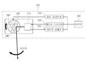
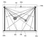
도 1에 도시된 바와 같이 본 발명의 터치검출장치를 포함하는 표시장치는, 표시부(100), 복수의 검출기(200), 복수의 반사기(300), 무반사 처리부(400), 제어 부(500) 등으로 구성된다. 그리고 표시장치의 상부에는 도 2에 도시된 바와 같이 커버(600)를 설치하여 표시장치 상부에 돌출되는 복수의 검출기(200), 복수의 반사기(300) 및 무반사 처리부(400) 등을 외부에 노출되지 않도록 미려하게 구성할 수 있다.As shown in FIG. 1, the display device including the touch detection device of the present invention includes a
표시부(100)는 제어부(500)의 제어에 따라 텍스트 및 그래픽으로 된 각종 기능이나 메뉴를 화면상에 표시한다.The
복수의 검출기(200)는 표시부(100)의 외곽에 설치되어 표시부(100) 상의 유효영역에 대한 레이저 스캔을 수행하며, 표시부(100) 상의 유효영역에 물체( 예를 들어, 사용자의 손가락, 펜 등 )가 접근함에 따라 반사신호가 검출되면 검출된 반사신호를 제어부(500)로 출력한다. 이때 검출기(200)는 도 1에 도시된 것처럼 표시부(100)의 상부 외곽 좌우에 각각 설치되는 것이 가장 바람직하지만 이에 한정되는 것은 아니며, 사용 환경에 따라 설치 위치와 수를 달리할 수 있다.The plurality of
각각의 검출기(200)는 레이저 드라이버(220)의 구동제어에 따라 터치검출을 위한 레이저의 발광을 수행하며, 터치를 수행하는 물체에 의한 반사신호를 수광하는 레이저 발광 및 수광부(210)와, 제어부(500)의 제어에 따라 레이저 발광 및 수광부(210)의 레이저 발광을 제어하는 레이저 드라이버(220)와, 레이저 발광 및 수광부(210)에서 수광된 반사신호를 증폭시켜 제어부(500)로 출력하는 레이저 검출부(230)와, 하나 이상의 반사면이 구비되고, 중심부는 회전축(250)에 결합되고, 레이저 발광 및 수광부(210)에서 발광된 레이저를 표시부(100) 상의 유효영역으로 반사시켜 레이저 스캔을 수행하도록 하며, 터치를 수행하는 물체에 의한 반사신호를 레이저 발광 및 수광부(210)로 반사시키는 반사거울(240)과, 반사거울(240)이 결합된 회전축(250)을 구동시켜 반사거울(240)의 회전 운동을 수행하는 회전모터(260)와, 제어부(500)의 제어에 따라 회전모터(260)가 소정의 속도로 구동하도록 구동신호를 인가하는 모터 드라이버(270) 등으로 구성된다.Each
그리고 복수의 검출기(200)는 각각 서로 다른 파장의 레이저를 사용하여 상호 간에 광신호가 혼선되지 않도록 하는 것이 바람직하며, 이 경우 레이저 발광 및 수광부(210)의 전면에 레이저 발광 및 수광부(210)에서 사용하는 특정 파장의 레이저만을 통과시키는 광 밴드패스 필터를 더 포함시켜 구성한다.In addition, the plurality of
그리고 회전모터(260)는 반사거울(240)을 특정 방향으로만 회전 운동하도록 회전축을 구동시키거나 또는 반사거울을 왕복 운동하도록 회전축(250)을 구동시킨다.The
복수의 반사기(300)는 표시부(100)의 외곽에 설치하되, 레이저 스캔을 수행하는 복수의 검출기(200)에서 유효영역의 끝을 인식할 수 있는 위치에 설치된다. 이때 반사기(300)는 도 1에 도시된 것처럼 검출기(200)의 설치 위치가 표시부(100)의 상부 좌우에 각각 설치되어 있다면, 표시부(100)의 상부 외곽 중앙 부분과, 각 검출기(200)와 수직선상인 표시부(100)의 하부 좌우에 총 3개를 설치하는 것이 가장 바람직하지만 이에 한정되는 것은 아니며, 사용 환경에 따라 설치 위치와 수를 달리할 수 있다.The plurality of
무반사 처리부(400)는 복수의 반사기(300)가 설치된 위치 이외의 영역에서 최소반사가 일어나도록 표시부(100) 상의 유효영역 바깥면을 따라 설치된다.The
제어부(500)는 표시부(100)를 통한 각종 기능이나 메뉴의 표시를 제어하고, 복수의 검출기(200)의 레이저 스캔을 제어하고, 복수의 검출기(200)에서 검출되는 반사신호를 토대로 사용자의 터치에 의한 표시부(100) 상의 특정 위치의 좌표를 인식하며, 인식된 좌표에 표시된 특정 기능이나 메뉴의 실행을 제어한다.The
이때 제어부(500)는 복수의 반사기(300)에 의한 반사신호 사이에 존재하는 표시부(100) 상의 물체에 의한 반사신호를 유효한 반사신호로 인식하고, 반사기(300)에 의한 반사신호와 복수의 검출기(200)에서 각각 검출되는 물체에 의한 반사신호 사이의 간격을 토대로 검출기(200)와 물체에 의한 반사가 이루어진 지점의 각도를 검출하며, 검출된 각도를 토대로 삼각법을 이용하여 단일 물체에 의한 반사가 이루어진 지점의 좌표를 연산한다.(후술되는 도 8 내지 도 10 참조)At this time, the
또한, 제어부(500)는 상술한 단일 물체의 터치검출 이외에, 2개 이상의 멀티 물체의 터치검출을 수행할 수도 있다. 이 경우 제어부(500)는 복수의 반사기(300)에 의한 반사신호 사이에 존재하는 표시부(100) 상의 2개 이상의 물체에 의한 반사신호들을 유효한 반사신호로 인식하고, 반사기(300)에 의한 반사신호와 복수의 검출기(200)에서 각각 검출되는 2개 이상의 물체에 의한 반사신호들 사이의 간격을 토대로 검출기(200)와 2개 이상의 물체에 의한 반사가 이루어진 지점들의 각도를 각각 검출하며, 검출된 각도를 토대로 삼각법을 이용하여 2개 이상의 물체에 의한 반사가 이루어진 지점들의 좌표를 각각 연산한다.(후술되는 도 11과 도 12 참조)In addition to the above-described touch detection of a single object, the
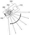
도 4와 도 5는 도 1의 각 검출기(200)에서 수행하는 레이저 스캔방식의 일 예를 설명하기 위한 도면으로서, 검출기(200)는 반사거울(240)의 회전에 따라 레이 저가 표시부(100)의 영역 전체로 회전하면서 스캔하고, 레이저 스캔의 유효영역 끝단에서 반사기(300)에 의한 최대 반사가 이루어지며, 무반사 처리부(400)가 구비된 그 이외의 영역에서는 최소 반사가 이루어진다. 레이저 스캔과정에서 표시부(100)의 유효영역에 손가락 등의 소정의 물체가 터치되면 그 물체에 의한 반사신호가 검출기(200)에 의해 검출된다.4 and 5 are diagrams for explaining an example of a laser scanning method performed by each
도 6은 도 1의 각 반사기(300)의 패턴구성의 일 예를 나타낸 도면으로서, 각 반사기(300)는 설치 위치에 따라 고유한 반사 패턴을 가지며, 최대 반사가 이루어지는 최대 반사 패턴부(310)와, 최소 반사가 이루어지는 무반사 패턴부(320)로 구성된다. 즉 검출기(200)의 레이저 스캔에 따라 최대 반사와 최소 반사가 번갈아 가면서 일어나도록 반사 패턴을 형성하는 것이다. 예를 들어 반사기가 3개가 구성된 경우, 제 1 반사기는 최대 반사 패턴부(310)와 무반사 패턴부(320)를 한 개 구성하고, 제 2 반사기는 최대 반사 패턴부(310)와 무반사 패턴부(320)를 번갈아 두 개를 구성하고, 제 3 반사기는 최대 반사 패턴부(310)와 무반사 패턴부(320)를 번갈아 세 개를 구성하는 반사 패턴을 형성한다.6 is a view showing an example of the pattern configuration of each
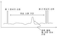
도 7은 도 1의 각 검출기(200)에서 반사신호 검출에 따라 출력되는 파형을 설명하기 위한 도면으로서, 각 검출기(200)에서의 레이저 스캔에 따라 유효 스캔 구간 양측에 서로 다른 2개의 반사기(300)( 검출기(200)의 수평 방향과 수직 방향에 각각 설치된 반사기(300) )에서 반사된 최대 반사 신호가 검출되며, 손가락 등의 접촉에 의한 반사신호는 유효 스캔 구간 사이에서 검출된다.FIG. 7 is a diagram illustrating waveforms output by the detection signals of the
도 8은 도 1의 각 검출기에서 수행하는 단일 물체의 터치검출의 일 예를 설 명하기 위한 도면이고, 도 9는 도 8에서의 단일 물체 터치검출에 따라 각 검출기에서 제어부로 출력되는 파형의 일 예를 설명하기 위한 도면이며, 도 10은 도 9의 각 검출기에서 터치검출에 따라 출력되는 파형을 토대로 제어부에서 수행하는 삼각법에 의한 좌표 연산의 일 예를 설명하기 위한 도면이다.FIG. 8 is a diagram illustrating an example of touch detection of a single object performed by each detector of FIG. 1, and FIG. 9 is a diagram of waveforms output from the respective detectors to the controller according to the single object touch detection of FIG. 8. FIG. 10 is a diagram for describing an example of coordinate calculation by a trigonometry performed by a controller based on waveforms output by touch detection in each detector of FIG. 9.
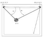
도 8에 도시된 바와 같이, 제 1, 제 2 검출기(200a)(200b)는 표시부(100) 상의 전체영역을 스캔할 수 있는 위치인 표시부(100) 외곽의 좌우 양쪽에 설치되어 있고, 제 1, 제 2, 제 3 반사기(300a)(300b)(300c)는 제 1, 제 2 검출기(200a)(200b) 사이의 중앙부분과 제 1, 제 2 검출기(200a)(200b) 각각의 수직방향의 하단에 설치되어 있다. 이때 제 1, 제 2 검출기(200a)(200b)는 상호 광 신호가 혼선되지 않도록 서로 다른 파장의 레이저를 사용한다.As shown in FIG. 8, the first and
제 1, 제 2 검출기(200a)(200b) 각각에서 레이저 스캔을 하는 과정에서 소정의 터치영역(110)에 물체가 위치( 즉 사용자의 손가락, 펜 등이 터치영역(110)에 터치 )하게 되면, 도 9에서와 같이 제 1 검출기(200a) 및 제 2 검출기(200b)에서 제어부(500)로 물체에 의한 반사신호가 각각 출력되며, 제어부(500)에서는 제 1, 제 2 검출기(200a)(200b)로부터 입력된 파형을 토대로 제 1 검출기(200a)와 물체에 의한 반사가 이루어진 지점 사이의 각도 θ1과, 제 2 검출기(200b)와 물체에 의한 반사가 이루어진 지점 사이의 각도 θ2를 검출한다. 즉 제어부(500)는 제 1 검출기(200a)로부터 입력된 파형을 토대로 제 1 반사기(300a)에 의한 반사신호와 물체에 의한 반사신호 사이의 간격으로 제 1 검출기(200a)와 물체에 의한 반사가 이루어진 지점의 각도를 검출하며, 제 2 검출기(200b)로부터 입력된 파형을 토대로 제 1 반사기(300a)에 의한 반사신호와 제 2 검출기(200a)에서 검출된 물체에 의한 반사신호 사이의 간격으로 제 2 검출기(200b)와 물체에 의한 반사가 이루어진 지점의 각도를 검출하는 것이다.When an object is placed in a predetermined touch area 110 (that is, a user's finger, pen, etc. touches the touch area 110) during a laser scan process in each of the first and
이처럼 제 1 검출기(200a)와 물체에 의한 반사가 이루어진 지점 사이의 각도 θ1과, 제 2 검출기(200b)와 물체에 의한 반사가 이루어진 지점 사이의 각도 θ2를 검출한 이후, 제어부(500)는 도 10에서와 같이 좌표를 알고 있는 지점( 즉 제 1, 제 2 검출기(200a)(200b) )과 두 지점 사이에 위치한 고유한 물체 사이의 각도( 즉 θ1과 θ2 )를 알면 하나의 고유한 물체의 좌표를 구할 수 있는 원리인 삼각법을 사용하여 터치가 이루어진 지점의 좌표를 연산한다. 이에 따라 제어부(500)는 해당 좌표에 표시되는 특정 기능이나 메뉴를 실행하기 위한 터치조작임을 확인하게 된다.After detecting the angle θ1 between the
도 11은 도 1의 각 검출기에서 수행하는 멀티 물체의 터치검출의 일 예를 설명하기 위한 도면이며, 도 12는 도 11에서의 멀티 물체 터치검출에 따라 각 검출기에서 제어부로 출력되는 파형의 일 예를 설명하기 위한 도면이다.FIG. 11 is a diagram illustrating an example of touch detection of multi-objects performed by each detector of FIG. 1, and FIG. 12 is an example of waveforms output from the respective detectors to the controller according to the multi-object touch detection of FIG. 11. A diagram for explaining.
도 11에 도시된 바와 같이, 제 1, 제 2 검출기(200a)(200b)는 표시부(100) 상의 전체영역을 스캔할 수 있는 위치인 표시부(100) 외곽의 좌우 양쪽에 설치되어 있고, 제 1, 제 2, 제 3 반사기(300a)(300b)(300c)는 제 1, 제 2 검출기(200a)(200b) 사이의 중앙부분과 제 1, 제 2 검출기(200a)(200b) 각각의 수직방향의 하단에 설치되어 있다.As illustrated in FIG. 11, the first and
제 1, 제 2 검출기(200a)(200b) 각각에서 레이저 스캔을 하는 과정에서 2개 의 터치영역(120)(130)에 물체가 위치하게 되면, 도 12에서와 같이 제 1 검출기(200a) 및 제 2 검출기(200b)에서 제어부(500)로 2개의 물체에 의한 반사신호가 각각 출력되며, 제어부(500)에서는 제 1, 제 2 검출기(200a)(200b)로부터 입력된 파형을 토대로 제 1 검출기(200a)와 2개의 물체에 의한 반사가 이루어진 지점 사이의 각도 θ11과 θ12, 제 2 검출기(200b)와 2개의 물체에 의한 반사가 이루어진 지점 사이의 각도 θ21, θ22를 검출한다.When an object is positioned in the two
이처럼 제 1 검출기(200a)와 2개의 물체에 의한 반사가 이루어진 지점 사이의 각도 θ11과 θ12, 제 2 검출기(200b)와 2개의 물체에 의한 반사가 이루어진 지점 사이의 각도 θ21, θ22를 검출한 이후, 제어부(500)는 전술한 도 10에서와 같이 삼각법을 사용하여 터치가 이루어진 2개 지점의 좌표를 연산한다. 이에 따라 제어부(500)는 해당 2개의 좌표에 표시되는 특정 기능이나 메뉴를 실행하기 위한 터치조작임을 확인하게 된다.After detecting the angles θ11 and θ12 between the
이때 상술한 도 11과 도 12는 2개의 물체에 의한 터치검출을 예로 설명하였으나, 전술한 설명을 토대로 2개가 아닌 그 이상의 물체에 의한 터치검출도 얼마든지 수행할 수 있음을 알 수 있다.11 and 12 have described touch detection by two objects as an example, but it can be seen that touch detection by two or more objects can be performed based on the above description.
다음에는, 이와 같이 구성된 본 발명에 따른 터치검출장치를 포함하는 표시장치에서의 좌표인식방법의 일 실시예를 도 13과 도 14를 참조하여 상세하게 설명한다.Next, an embodiment of the coordinate recognition method in the display device including the touch detection device according to the present invention configured as described above will be described in detail with reference to FIGS. 13 and 14.
도 13과 도 14는 본 발명의 터치검출을 수행하는 표시장치에서의 좌표인식방법의 일 실시예의 동작과정을 상세하게 나타낸 순서도이다.13 and 14 are flowcharts illustrating in detail an operation of an embodiment of a coordinate recognition method in a display device for performing touch detection according to the present invention.
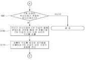
우선, 표시부(100) 외곽에 설치된 복수의 검출기(200)는 제어부(500)의 제어에 따라 레이저를 발광시켜 표시부(100) 상의 유효영역의 레이저 스캔을 수행한다(S10).First, the plurality of
이때 S10 단계에서 수행하는 레이저 스캔은, 복수의 검출기(200) 내에 구비된 하나 이상의 반사면을 갖는 반사거울(240)을 회전시키고, 복수의 검출기(200) 내에 구비된 레이저 발광 및 수광부(210)에서 발광된 레이저를 회전 구동되는 반사거울(240)을 통해 서로 다른 각도로 표시부(100) 상의 유효영역으로 반사시켜, 표시부(100) 상의 유효영역 전체를 처리하는 방식의 레이저 스캔이다. 그리고 S10 단계에서 수행하는 레이저 스캔은, 각 검출기(200)마다 서로 다른 파장의 레이저를 사용하여 수행한다.In this case, the laser scan performed in step S10 rotates the
S10 단계를 통해 표시부(100) 상의 유효영역의 레이저 스캔을 수행하는 복수의 검출기(200)는 소정 위치에 터치를 수행하는 물체에 의한 반사신호가 검출되는지를 판단하고(S20), 물체에 의한 반사신호가 검출되면 검출된 반사신호를 제어부(500)로 출력한다(S30).In operation S10, the plurality of
제어부(500)는 S30 단계를 통해 복수의 검출기(200)에서 검출된 물체에 의한 반사신호가 입력되면, 해당 반사신호가 하나인지 아니면 2개 이상인지를 판단한다(S40).When the reflection signals by the objects detected by the plurality of
판단결과 복수의 검출기(200)에서 검출된 물체에 의한 반사신호가 하나이면, 제어부(500)는 복수의 검출기(200)에서 검출된 물체에 의한 반사신호가 레이저 스캔을 수행하는 복수의 검출기(200)에서 유효영역의 끝을 인식할 수 있는 위치에 설 치된 복수의 반사기(300)에 의한 반사신호 사이에 존재하는 유효한 반사신호인지를 판단한다(S50). 즉 물체에 의한 하나의 반사신호가 복수의 반사기(300)에 의한 반사신호 사이의 유효 스캔 영역에 위치하는지를 판단하는 것이다.As a result of the determination, when the reflection signal of the objects detected by the plurality of
판단결과 물체에 의한 반사신호가 유효한 반사신호이면, 제어부(500)는 반사기(300)에 의한 반사신호와 복수의 검출기(200)에서 각각 검출되는 물체에 의한 반사신호 사이의 간격을 토대로 검출기(200)와 물체에 의한 반사가 이루어진 지점의 각도를 검출한다(S60). 즉 제어부(500)는 어느 하나의 검출기(200)로부터 입력된 파형을 토대로 반사기(300)에 의한 반사신호와 물체에 의한 반사신호 사이의 간격으로 어느 하나의 검출기(200)와 물체에 의한 반사가 이루어진 지점의 각도를 검출하며, 다른 하나의 검출기(200)로부터 입력된 파형을 토대로 반사기(300)에 의한 반사신호와 물체에 의한 반사신호 사이의 간격으로 다른 하나의 검출기(200)와 물체에 의한 반사가 이루어진 지점의 각도를 검출하는 것이다.As a result of the determination, if the reflection signal by the object is a valid reflection signal, the
검출기(200)와 물체에 의한 반사가 이루어진 지점 사이의 각도를 검출한 이후, 제어부(500)는 S60 단계에서 검출된 각도를 토대로 삼각법을 이용하여 물체에 의한 반사가 이루어진 지점의 좌표를 인식한다(S70). 즉 제어부(500)는 좌표를 알고 있는 각각의 검출기(200)의 좌표와 각각의 검출기(200) 사이에 위치한 물체 사이의 각도를 토대로 해당 물체의 좌표를 구할 수 있는 원리인 삼각법을 사용하여 터치가 이루어진 지점의 좌표를 연산하는 것이다.After detecting the angle between the
S70 단계를 통해 물체에 의한 반사가 이루어진 지점의 좌표를 인식한 이후, 제어부(500)는 인식된 좌표에 표시되어 있는 특정 기능이나 메뉴의 실행을 제어한 다(S80).After recognizing the coordinates of the reflection point by the object through the step S70, the
한편, 상술한 S40 단계의 판단결과 복수의 검출기(200)에서 검출된 물체에 의한 반사신호가 2개 이상이면, 제어부(500)는 복수의 검출기(200)에서 검출된 2개 이상의 물체에 의한 반사신호가 레이저 스캔을 수행하는 복수의 검출기(200)에서 유효영역의 끝을 인식할 수 있는 위치에 설치된 복수의 반사기(300)에 의한 반사신호 사이에 존재하는 유효한 반사신호인지를 판단한다(S90).On the other hand, if the determination result of the above-described step S40 is two or more reflection signals by the objects detected by the plurality of
판단결과 2개 이상의 물체에 의한 반사신호가 유효한 반사신호이면, 제어부(500)는 반사기(300)에 의한 반사신호와 복수의 검출기(200)에서 각각 검출되는 2개 이상의 물체에 의한 반사신호들 사이의 간격을 토대로 검출기(200)와 2개 이상의 물체에 의한 반사가 이루어진 지점들의 각도를 각각 검출한다(S100).As a result of the determination, if the reflection signal by two or more objects is a valid reflection signal, the
검출기(200)와 2개 이상의 물체에 의한 반사가 이루어진 지점 사이의 각도를 검출한 이후, 제어부(500)는 검출된 각도를 토대로 삼각법을 이용하여 2개 이상의 물체에 의한 반사가 이루어진 지점들의 좌표를 각각 인식하고(S110), 상술한 S80 단계 이후를 수행한다.After detecting the angle between the
여기에서, 상술한 본 발명에서는 바람직한 실시예를 참조하여 설명하였지만, 해당 기술분야의 숙련된 당업자는 하기의 특허청구범위에 기재된 본 발명의 사상 및 영역으로부터 벗어나지 않는 범위 내에서 본 발명을 다양하게 수정 및 변경할 수 있음을 이해할 수 있을 것이다.Herein, while the present invention has been described with reference to the preferred embodiments, those skilled in the art will variously modify the present invention without departing from the spirit and scope of the invention as set forth in the claims below. And can be changed.
도 1은 본 발명에 따른 터치검출장치를 포함하는 표시장치의 일 실시예의 구성을 개략적으로 나타낸 도면,1 is a view schematically showing a configuration of an embodiment of a display device including a touch detection device according to the present invention;
도 2는 도 1의 표시장치의 상부에 커버가 결합되는 구성을 나타낸 도면,2 is a view illustrating a configuration in which a cover is coupled to an upper portion of the display device of FIG. 1;
도 3은 도 1의 각 검출기의 일 실시예의 구성을 보다 상세하게 나타낸 도면,3 is a view showing in more detail the configuration of an embodiment of each detector of FIG.
도 4와 도 5는 도 1의 각 검출기에서 수행하는 레이저 스캔방식의 일 예를 설명하기 위한 도면,4 and 5 are views for explaining an example of a laser scanning method performed by each detector of FIG.
도 6은 도 1의 각 반사기의 패턴구성의 일 예를 나타낸 도면,6 is a view showing an example of the pattern configuration of each reflector of FIG.
도 7은 도 1의 각 검출기에서 반사신호 검출에 따라 출력되는 파형을 설명하기 위한 도면,7 is a view for explaining a waveform output by the detection of the reflected signal in each detector of FIG.
도 8은 도 1의 각 검출기에서 수행하는 단일 물체의 터치검출의 일 예를 설명하기 위한 도면,8 is a view for explaining an example of touch detection of a single object performed by each detector of FIG.
도 9는 도 8에서의 단일 물체 터치검출에 따라 각 검출기에서 제어부로 출력되는 파형의 일 예를 설명하기 위한 도면,FIG. 9 is a view for explaining an example of a waveform output from each detector to a control unit according to the single object touch detection in FIG. 8; FIG.
도 10은 도 9의 각 검출기에서 터치검출에 따라 출력되는 파형을 토대로 제어부에서 수행하는 삼각법에 의한 좌표 연산의 일 예를 설명하기 위한 도면,FIG. 10 is a view for explaining an example of coordinate calculation by a trigonometric method performed by a control unit based on a waveform output by touch detection in each detector of FIG. 9; FIG.
도 11은 도 1의 각 검출기에서 수행하는 멀티 물체의 터치검출의 일 예를 설명하기 위한 도면,FIG. 11 is a view for explaining an example of touch detection of multiple objects performed by each detector of FIG. 1; FIG.
도 12는 도 11에서의 멀티 물체 터치검출에 따라 각 검출기에서 제어부로 출력되는 파형의 일 예를 설명하기 위한 도면,12 is a view for explaining an example of a waveform output from each detector to a control unit according to the multi-object touch detection in FIG. 11;
도 13과 도 14는 본 발명의 터치검출을 수행하는 표시장치에서의 좌표인식방법의 일 실시예의 동작과정을 상세하게 나타낸 순서도이다.13 and 14 are flowcharts illustrating in detail an operation of an embodiment of a coordinate recognition method in a display device for performing touch detection according to the present invention.
* 도면의 주요부분에 대한 부호의 설명 *Explanation of symbols on the main parts of the drawings
100 : 표시부 110, 120, 130 : 터치영역100:
200, 200a, 200b : 검출기 210 : 레이저 발광 및 수광부200, 200a, 200b: detector 210: laser light emitting and receiving portion
220 : 레이저 드라이버 230 : 레이저 검출부220: laser driver 230: laser detection unit
240 : 반사거울 250 : 회전축240: reflection mirror 250: rotation axis
260 : 회전모터 270 : 모터 드라이버260: rotary motor 270: motor driver
300, 300a, 300b, 300c : 반사기 310 : 최대 반사 패턴부300, 300a, 300b, 300c: reflector 310: maximum reflection pattern portion
320 : 무반사 패턴부 400 : 무반사 처리부320: anti-reflective pattern portion 400: anti-reflective processing portion
500 : 제어부500: control unit
Claims (17)
Translated fromKoreanPriority Applications (1)
| Application Number | Priority Date | Filing Date | Title |
|---|---|---|---|
| KR1020090047745AKR20100129015A (en) | 2009-05-29 | 2009-05-29 | Touch detection device, display device and coordinate recognition method comprising the same |
Applications Claiming Priority (1)
| Application Number | Priority Date | Filing Date | Title |
|---|---|---|---|
| KR1020090047745AKR20100129015A (en) | 2009-05-29 | 2009-05-29 | Touch detection device, display device and coordinate recognition method comprising the same |
Publications (1)
| Publication Number | Publication Date |
|---|---|
| KR20100129015Atrue KR20100129015A (en) | 2010-12-08 |
Family
ID=43505820
Family Applications (1)
| Application Number | Title | Priority Date | Filing Date |
|---|---|---|---|
| KR1020090047745ACeasedKR20100129015A (en) | 2009-05-29 | 2009-05-29 | Touch detection device, display device and coordinate recognition method comprising the same |
Country Status (1)
| Country | Link |
|---|---|
| KR (1) | KR20100129015A (en) |
Cited By (16)
| Publication number | Priority date | Publication date | Assignee | Title |
|---|---|---|---|---|
| WO2012144998A1 (en)* | 2011-04-20 | 2012-10-26 | Mellmo Inc. | User interface for data comparison |
| WO2013009335A1 (en)* | 2011-07-14 | 2013-01-17 | Microsoft Corporation | Multi-finger detection and component resolution |
| WO2012170982A3 (en)* | 2011-06-10 | 2013-03-07 | Texas Instruments Incorporated | Touch screen |
| US8725443B2 (en) | 2011-01-24 | 2014-05-13 | Microsoft Corporation | Latency measurement |
| US8773377B2 (en) | 2011-03-04 | 2014-07-08 | Microsoft Corporation | Multi-pass touch contact tracking |
| WO2014129825A1 (en)* | 2013-02-21 | 2014-08-28 | 주식회사 실리콘웍스 | Coordinate selection circuit and method in differential touch sensing system |
| US8914254B2 (en) | 2012-01-31 | 2014-12-16 | Microsoft Corporation | Latency measurement |
| US8982061B2 (en) | 2011-02-12 | 2015-03-17 | Microsoft Technology Licensing, Llc | Angular contact geometry |
| US8988087B2 (en) | 2011-01-24 | 2015-03-24 | Microsoft Technology Licensing, Llc | Touchscreen testing |
| US9239672B2 (en) | 2011-04-20 | 2016-01-19 | Mellmo Inc. | User interface for data comparison |
| US9317147B2 (en) | 2012-10-24 | 2016-04-19 | Microsoft Technology Licensing, Llc. | Input testing tool |
| KR20160054376A (en)* | 2014-11-06 | 2016-05-16 | 주식회사 앱스 | Apparatus for sensing the Position of an Object |
| US9378389B2 (en) | 2011-09-09 | 2016-06-28 | Microsoft Technology Licensing, Llc | Shared item account selection |
| US9542092B2 (en) | 2011-02-12 | 2017-01-10 | Microsoft Technology Licensing, Llc | Prediction-based touch contact tracking |
| US9785281B2 (en) | 2011-11-09 | 2017-10-10 | Microsoft Technology Licensing, Llc. | Acoustic touch sensitive testing |
| KR102242478B1 (en)* | 2019-11-20 | 2021-04-21 | 주식회사 센서리움 | Method for generating coordinate information based on touch area performed by interactive system having a pair of laser scanners, and the interactive system using the same |
- 2009
- 2009-05-29KRKR1020090047745Apatent/KR20100129015A/ennot_activeCeased
Cited By (23)
| Publication number | Priority date | Publication date | Assignee | Title |
|---|---|---|---|---|
| US9395845B2 (en) | 2011-01-24 | 2016-07-19 | Microsoft Technology Licensing, Llc | Probabilistic latency modeling |
| US8988087B2 (en) | 2011-01-24 | 2015-03-24 | Microsoft Technology Licensing, Llc | Touchscreen testing |
| US9965094B2 (en) | 2011-01-24 | 2018-05-08 | Microsoft Technology Licensing, Llc | Contact geometry tests |
| US8725443B2 (en) | 2011-01-24 | 2014-05-13 | Microsoft Corporation | Latency measurement |
| US9710105B2 (en) | 2011-01-24 | 2017-07-18 | Microsoft Technology Licensing, Llc. | Touchscreen testing |
| US9030437B2 (en) | 2011-01-24 | 2015-05-12 | Microsoft Technology Licensing, Llc | Probabilistic latency modeling |
| US9542092B2 (en) | 2011-02-12 | 2017-01-10 | Microsoft Technology Licensing, Llc | Prediction-based touch contact tracking |
| US8982061B2 (en) | 2011-02-12 | 2015-03-17 | Microsoft Technology Licensing, Llc | Angular contact geometry |
| US8773377B2 (en) | 2011-03-04 | 2014-07-08 | Microsoft Corporation | Multi-pass touch contact tracking |
| WO2012144998A1 (en)* | 2011-04-20 | 2012-10-26 | Mellmo Inc. | User interface for data comparison |
| US9239672B2 (en) | 2011-04-20 | 2016-01-19 | Mellmo Inc. | User interface for data comparison |
| WO2012170982A3 (en)* | 2011-06-10 | 2013-03-07 | Texas Instruments Incorporated | Touch screen |
| US10949024B2 (en) | 2011-06-10 | 2021-03-16 | Texas Instruments Incorporated | Touch screen |
| US8913019B2 (en) | 2011-07-14 | 2014-12-16 | Microsoft Corporation | Multi-finger detection and component resolution |
| WO2013009335A1 (en)* | 2011-07-14 | 2013-01-17 | Microsoft Corporation | Multi-finger detection and component resolution |
| US9378389B2 (en) | 2011-09-09 | 2016-06-28 | Microsoft Technology Licensing, Llc | Shared item account selection |
| US9935963B2 (en) | 2011-09-09 | 2018-04-03 | Microsoft Technology Licensing, Llc | Shared item account selection |
| US9785281B2 (en) | 2011-11-09 | 2017-10-10 | Microsoft Technology Licensing, Llc. | Acoustic touch sensitive testing |
| US8914254B2 (en) | 2012-01-31 | 2014-12-16 | Microsoft Corporation | Latency measurement |
| US9317147B2 (en) | 2012-10-24 | 2016-04-19 | Microsoft Technology Licensing, Llc. | Input testing tool |
| WO2014129825A1 (en)* | 2013-02-21 | 2014-08-28 | 주식회사 실리콘웍스 | Coordinate selection circuit and method in differential touch sensing system |
| KR20160054376A (en)* | 2014-11-06 | 2016-05-16 | 주식회사 앱스 | Apparatus for sensing the Position of an Object |
| KR102242478B1 (en)* | 2019-11-20 | 2021-04-21 | 주식회사 센서리움 | Method for generating coordinate information based on touch area performed by interactive system having a pair of laser scanners, and the interactive system using the same |
Similar Documents
| Publication | Publication Date | Title |
|---|---|---|
| KR20100129015A (en) | Touch detection device, display device and coordinate recognition method comprising the same | |
| US8115753B2 (en) | Touch screen system with hover and click input methods | |
| US10324566B2 (en) | Enhanced interaction touch system | |
| US8681124B2 (en) | Method and system for recognition of user gesture interaction with passive surface video displays | |
| EP1759378B1 (en) | Touch panel display system with illumination and detection provided from a single edge | |
| US8711125B2 (en) | Coordinate locating method and apparatus | |
| JP5876587B2 (en) | Touch screen system and controller | |
| CN103176592B (en) | Virtual projection input system and input detection method thereof | |
| TWI511006B (en) | Optical image touch system and touch image processing method | |
| CN104298405B (en) | Touch module, projection system and touch method thereof | |
| US11392214B2 (en) | Touch control system and method | |
| KR20110138975A (en) | Coordinate recognition device and display device, security device and electronic blackboard including same | |
| TWI461990B (en) | Optical imaging device and image processing method for optical imaging device | |
| JP5764266B2 (en) | Light-based touch-sensitive electronic device | |
| CN101855609A (en) | Touch surface and system and method for detecting touch input | |
| US20170170826A1 (en) | Optical sensor based mechanical keyboard input system and method | |
| US8912482B2 (en) | Position determining device and method for objects on a touch device having a stripped L-shaped reflecting mirror and a stripped retroreflector | |
| KR101125824B1 (en) | Infrared touch screen devices | |
| CN102129330A (en) | Touch screen, touch module and control method | |
| US12314482B2 (en) | Touch control system and method | |
| KR101221677B1 (en) | Infrared touch screen device | |
| JP2000284897A (en) | Starter for optical scanning touch panel | |
| HK1153830B (en) | Coordinate locating method and apparatus |
Legal Events
| Date | Code | Title | Description |
|---|---|---|---|
| PA0109 | Patent application | Patent event code:PA01091R01D Comment text:Patent Application Patent event date:20090529 | |
| A201 | Request for examination | ||
| PA0201 | Request for examination | Patent event code:PA02012R01D Patent event date:20090609 Comment text:Request for Examination of Application Patent event code:PA02011R01I Patent event date:20090529 Comment text:Patent Application | |
| PG1501 | Laying open of application | ||
| E902 | Notification of reason for refusal | ||
| PE0902 | Notice of grounds for rejection | Comment text:Notification of reason for refusal Patent event date:20110112 Patent event code:PE09021S01D | |
| E601 | Decision to refuse application | ||
| PE0601 | Decision on rejection of patent | Patent event date:20110811 Comment text:Decision to Refuse Application Patent event code:PE06012S01D Patent event date:20110112 Comment text:Notification of reason for refusal Patent event code:PE06011S01I |