KR20100125029A - Cleaning cassette and cassette storage system having the same - Google Patents
Cleaning cassette and cassette storage system having the sameDownload PDFInfo
- Publication number
- KR20100125029A KR20100125029AKR1020090044025AKR20090044025AKR20100125029AKR 20100125029 AKR20100125029 AKR 20100125029AKR 1020090044025 AKR1020090044025 AKR 1020090044025AKR 20090044025 AKR20090044025 AKR 20090044025AKR 20100125029 AKR20100125029 AKR 20100125029A
- Authority
- KR
- South Korea
- Prior art keywords
- cassette
- shelf
- charging
- unit
- vacuum suction
- Prior art date
- Legal status (The legal status is an assumption and is not a legal conclusion. Google has not performed a legal analysis and makes no representation as to the accuracy of the status listed.)
- Granted
Links
Images


Classifications
- G—PHYSICS
- G02—OPTICS
- G02F—OPTICAL DEVICES OR ARRANGEMENTS FOR THE CONTROL OF LIGHT BY MODIFICATION OF THE OPTICAL PROPERTIES OF THE MEDIA OF THE ELEMENTS INVOLVED THEREIN; NON-LINEAR OPTICS; FREQUENCY-CHANGING OF LIGHT; OPTICAL LOGIC ELEMENTS; OPTICAL ANALOGUE/DIGITAL CONVERTERS
- G02F1/00—Devices or arrangements for the control of the intensity, colour, phase, polarisation or direction of light arriving from an independent light source, e.g. switching, gating or modulating; Non-linear optics
- G02F1/01—Devices or arrangements for the control of the intensity, colour, phase, polarisation or direction of light arriving from an independent light source, e.g. switching, gating or modulating; Non-linear optics for the control of the intensity, phase, polarisation or colour
- G02F1/13—Devices or arrangements for the control of the intensity, colour, phase, polarisation or direction of light arriving from an independent light source, e.g. switching, gating or modulating; Non-linear optics for the control of the intensity, phase, polarisation or colour based on liquid crystals, e.g. single liquid crystal display cells
- G02F1/1303—Apparatus specially adapted to the manufacture of LCDs
- B—PERFORMING OPERATIONS; TRANSPORTING
- B65—CONVEYING; PACKING; STORING; HANDLING THIN OR FILAMENTARY MATERIAL
- B65G—TRANSPORT OR STORAGE DEVICES, e.g. CONVEYORS FOR LOADING OR TIPPING, SHOP CONVEYOR SYSTEMS OR PNEUMATIC TUBE CONVEYORS
- B65G49/00—Conveying systems characterised by their application for specified purposes not otherwise provided for
- B65G49/05—Conveying systems characterised by their application for specified purposes not otherwise provided for for fragile or damageable materials or articles
- B65G49/06—Conveying systems characterised by their application for specified purposes not otherwise provided for for fragile or damageable materials or articles for fragile sheets, e.g. glass
- H—ELECTRICITY
- H01—ELECTRIC ELEMENTS
- H01L—SEMICONDUCTOR DEVICES NOT COVERED BY CLASS H10
- H01L21/00—Processes or apparatus adapted for the manufacture or treatment of semiconductor or solid state devices or of parts thereof
- H01L21/02—Manufacture or treatment of semiconductor devices or of parts thereof
- H01L21/02041—Cleaning
- H—ELECTRICITY
- H01—ELECTRIC ELEMENTS
- H01L—SEMICONDUCTOR DEVICES NOT COVERED BY CLASS H10
- H01L21/00—Processes or apparatus adapted for the manufacture or treatment of semiconductor or solid state devices or of parts thereof
- H01L21/67—Apparatus specially adapted for handling semiconductor or electric solid state devices during manufacture or treatment thereof; Apparatus specially adapted for handling wafers during manufacture or treatment of semiconductor or electric solid state devices or components ; Apparatus not specifically provided for elsewhere
- H01L21/677—Apparatus specially adapted for handling semiconductor or electric solid state devices during manufacture or treatment thereof; Apparatus specially adapted for handling wafers during manufacture or treatment of semiconductor or electric solid state devices or components ; Apparatus not specifically provided for elsewhere for conveying, e.g. between different workstations
- H01L21/67703—Apparatus specially adapted for handling semiconductor or electric solid state devices during manufacture or treatment thereof; Apparatus specially adapted for handling wafers during manufacture or treatment of semiconductor or electric solid state devices or components ; Apparatus not specifically provided for elsewhere for conveying, e.g. between different workstations between different workstations
- H01L21/6773—Conveying cassettes, containers or carriers
Landscapes
- Engineering & Computer Science (AREA)
- Physics & Mathematics (AREA)
- Manufacturing & Machinery (AREA)
- General Physics & Mathematics (AREA)
- Microelectronics & Electronic Packaging (AREA)
- Computer Hardware Design (AREA)
- Condensed Matter Physics & Semiconductors (AREA)
- Power Engineering (AREA)
- Nonlinear Science (AREA)
- Chemical & Material Sciences (AREA)
- Crystallography & Structural Chemistry (AREA)
- Optics & Photonics (AREA)
- Warehouses Or Storage Devices (AREA)
Abstract
Translated fromKoreanDescription
Translated fromKorean본 발명은, 클리닝 카세트 및그를 구비하는 카세트 보관 시스템에 관한 것으로서, 보다 상세하게는, 카세트 보관 시스템의 선반 상에 잔존되는 파티클(particle)을 용이하게 제거할 수 있으며, 특히 동작을 위한 전원 공급을 간편하게 수행할 수 있는 클리닝 카세트 및그를 구비하는 카세트 보관 시스템에 관한 것이다.The present invention relates to a cleaning cassette and a cassette storage system having the same, and more particularly, to easily remove particles remaining on a shelf of a cassette storage system, and particularly to provide a power supply for operation. A cleaning cassette that can be easily performed and a cassette storage system having the same.
플라즈마 디스플레이(PDP, Plasma Display Panel), 액정디스플레이(LCD, Liquid Crystal Display) 및 유기EL(OLED, Organic Light Emitting Diodes)과 같은 평판표시소자(FPD, Flat Panel Display)에서 특히, 글라스(glass) 기판의 역할과 기능은 갈수록 중요한 과제로 대두되고 있다. 이는 글라스 기판에 형성되는 다수의 회로소자의 기능에 따라 평판표시장치의 전체적인 품질이 많은 영향을 받기 때문이다.Glass substrates, especially in flat panel displays (FPDs) such as plasma displays (PDPs), liquid crystal displays (LCDs) and organic light emitting diodes (OLEDs) 'S role and function are becoming more and more important tasks. This is because the overall quality of the flat panel display device is greatly affected by the functions of the plurality of circuit elements formed on the glass substrate.
생산 현장에서 작업 효율을 최대화하고 청정도를 높이기 위해 여러 공정을 거쳐 완성된 글라스 기판(이하, 기판이라 함)들은 반송 로봇(robot)을 통해 기판 수납용 카세트(Cassette)에 수납되고, 기판들을 수납한 기판 수납용 카세트는 카세트 스토커에 의해 운반되어지며, 카세트 보관 시스템의 선반에 적재되어 보관되거나 역과정을 통해 반출된다.In order to maximize work efficiency and increase cleanliness at the production site, glass substrates (hereinafter referred to as substrates) completed through various processes are stored in a substrate storage cassette through a transfer robot and the substrates are stored. Substrate receiving cassettes are carried by a cassette stocker, stored on shelves in a cassette storage system, or taken out in reverse.
이에 대해 부연하면, 다수의 기판이 수납된 기판 수납용 카세트는 어느 한 평판표시소자 제조 설비에서 해당 공정이 완료된 후 다음의 평판표시소자 제조 설비로 바로 이송되는 것은 아니다.In this regard, the substrate storage cassette in which the plurality of substrates are stored is not directly transferred to the next flat panel display device manufacturing facility after the process is completed in one flat panel display device manufacturing facility.
즉 평판표시소자 제조 설비들의 기판 처리 능력 및 시간의 차이에 의해 발생되는 버퍼링(buffering) 문제를 해소하기 위하여, 다수의 기판이 수납된 기판 수납용 카세트는 카세트 보관 시스템의 선반에 임시로 보관되며, 필요에 따라 해당 공정을 수행하는 평판표시소자 제조 설비로 이송된다. 이때, 기판 수납용 카세트를 카세트 보관 시스템의 선반에 적재하거나 또는 반출할 때 카세트 스토커가 사용된다.That is, in order to solve the buffering problem caused by the difference in substrate processing capacity and time of the flat panel display device manufacturing facilities, a substrate storage cassette in which a plurality of substrates are stored is temporarily stored on a shelf of a cassette storage system. If necessary, it is transferred to a flat panel display manufacturing equipment that performs the process. At this time, a cassette stocker is used when the cassette for storing the substrate is loaded or taken out on the shelf of the cassette storage system.
한편, 카세트 스토커에 의해 기판 수납용 카세트가 카세트 보관 시스템의 선반에 적재되거나 반출되는 과정이 빈번하게 진행됨에 따라 카세트 보관 시스템의 선반 상에는 파티클(particle)이 떨어져 잔존될 수 있는데, 이러한 파티클을 제거(클리닝, cleaning)하지 않으면 파티클로 인한 공정 불량이 야기될 수 있다.On the other hand, as the cassette stocker frequently loads or unloads the substrate storage cassette onto the shelf of the cassette storage system, particles may fall off and remain on the shelf of the cassette storage system. Failure to clean may result in process defects due to particles.
따라서 이러한 파티클 제거하기 위한 선반의 클리닝(cleaning)이 필요한데, 수작업에 의한 선반의 클리닝 작업은 효율적이지 못하기 때문에, 통상의 기판 수납용 카세트와 대략 엇비슷한 사이즈로 제작되어 기판 수납용 카세트 대신에 카세트 보관 시스템의 선반에 안착됨으로써 선반 상의 파티클을 제거할 수 있는 클리닝 카 세트(cleaning cassette)의 필요성이 대두된다.Therefore, since the cleaning of the shelf for removing such particles is necessary, the cleaning of the shelf by manual labor is not efficient, and is manufactured in a size approximately the same as that of a conventional substrate storage cassette. The need for a cleaning cassette to remove particles on the shelf by placing it on the shelf of the storage system has emerged.
다만, 카세트 보관 시스템의 선반은 큰 구조물일 수 있고, 클리닝 카세트 역시 선반에 상응하는 큰 구조물일 수 있다는 점을 고려할 때, 큰 구조물인 클리닝 카세트의 동작을 위한 전원 공급이 용이할 필요가 있으며, 따라서 이에 대한 연구 개발이 필요한 실정이다.However, considering that the shelf of the cassette storage system may be a large structure and the cleaning cassette may also be a large structure corresponding to the shelf, it is necessary to easily supply power for the operation of the cleaning cassette, which is a large structure, and thus This is a situation that requires research and development.
본 발명의 목적은, 카세트 보관 시스템의 선반 상에 잔존되는 파티클(particle)을 용이하게 제거할 수 있으며, 특히 동작을 위한 전원 공급을 간편하게 수행할 수 있는 클리닝 카세트 및그를 구비하는 카세트 보관 시스템을 제공하는 것이다.SUMMARY OF THE INVENTION An object of the present invention is to provide a cleaning cassette and a cassette storage system having the same, which can easily remove particles remaining on a shelf of a cassette storage system, and in particular, can easily perform a power supply for operation. It is.
상기 목적은, 본 발명에 따라, 다수의 기판이 수납된 기판 수납용 카세트가 안착 지지되는 다수의 선반을 구비하는 시스템 본체; 전원 유닛을 구비하며, 하단부의 적어도 일 영역이 상기 선반에 안착 지지되어 상기 선반 상의 파티클(particle)을 제거하는(cleaning) 클리닝 카세트; 및 적어도 어느 한 선반과 상기 클리닝 카세트에 마련되며, 해당 선반에 상기 클리닝 카세트가 안착 지지될 때 상기 전원 유닛에 전기적으로 연결되어 상기 전원 유닛에 전원을 충전시키는 전원 연결 유닛을 포함하는 것을 특징으로 하는 카세트 보관 시스템에 의해 달성된다.The above object is, according to the present invention, a system body having a plurality of shelves on which the substrate holding cassette in which a plurality of substrates are accommodated is seated and supported; A cleaning cassette having a power supply unit, wherein at least one region of a lower end is seated and supported on the shelf to remove particles on the shelf; And a power connection unit provided on at least one shelf and the cleaning cassette, and electrically connected to the power unit to charge power to the power unit when the cleaning cassette is seated and supported on the shelf. Achieved by a cassette storage system.
여기서, 상기 전원 연결 유닛은, 상기 선반에 마련되되 적어도 하나의 충전 핀을 구비하는 충전 스테이션; 및 상기 클리닝 카세트에 마련되어 상기 충전 핀과 전기적으로 연결되는 충전 단자를 포함할 수 있다.The power connection unit may include a charging station provided on the shelf and having at least one charging pin; And a charging terminal provided in the cleaning cassette and electrically connected to the charging pin.
상기 충전 스테이션은, 몸체부; 상기 충전 핀을 지지하되 상기 몸체부 내에서 충전 핀과 함께 승하강 이동되는 핀 지지블록; 상기 핀 지지블록과 연결되어 상기 충전 핀의 승하강 이동 축선을 형성하는 샤프트; 상기 샤프트와 이격된 위치에서 상기 샤프트의 하부 영역에 마련되는 센서; 및 상기 샤프트의 하단부에 결합되며, 상기 클리닝 카세트의 충전 단자가 상기 선반의 충전 핀에 접촉되어 상기 클리닝 카세트의 무게로 상기 충전 핀을 가압할 때 상기 샤프트와 함께 하향 이동되어 상기 센서와의 상호 작용에 의해 상기 센서가 충전을 위한 전기적인 접점 신호를 발생시키도록 하는 센서 도그(sensor dog)를 포함할 수 있다.The charging station, the body portion; A pin support block supporting the charging pin and moving up and down together with the charging pin in the body portion; A shaft connected to the pin support block to form a lifting movement axis of the charging pin; A sensor provided in a lower region of the shaft at a position spaced apart from the shaft; And coupled to a lower end of the shaft, when the charging terminal of the cleaning cassette is in contact with the charging pin of the shelf to press the charging pin with the weight of the cleaning cassette to move downward with the shaft to interact with the sensor. And a sensor dog to cause the sensor to generate an electrical contact signal for charging.
상기 충전 스테이션은 상기 샤프트에 결합되어 상기 샤프트의 승하강 이동을 안내하는 엘엠 부시(LM bush)를 더 포함할 수 있다.The charging station may further include an LM bush coupled to the shaft to guide the lifting movement of the shaft.
상기 충전 스테이션은 상기 핀 지지블록과 상기 엘엠 부시에 연결되어 상기 충전 핀이 원위치로 복귀되는 방향으로 탄성바이어스시키는 탄성부재를 더 포함할 수 있다.The charging station may further include an elastic member connected to the pin support block and the LM bush to elastically bias in the direction in which the charging pin is returned to its original position.
상기 탄성부재는 압축식 코일 스프링일 수 있으며, 상기 센서는 상기 선반의 센서 브래킷(sensor bracket)에 지지되는 근접 센서일 수 있으며, 상기 충전 단자, 상기 충전 핀, 상기 샤프트, 상기 센서, 상기 센서 도그 및 상기 탄성부재는 3개씩 마련되고, 상기 핀 지지블록과 상기 엘엠 부시는 1개씩 마련될 수 있다.The elastic member may be a compression coil spring, and the sensor may be a proximity sensor supported by a sensor bracket of the shelf, wherein the charging terminal, the charging pin, the shaft, the sensor, and the sensor dog And three elastic members, and the pin support block and the L bush may be provided one by one.
상기 클리닝 카세트는, 하단부의 일 영역이 상기 선반에 선택적으로 안착 지 지되며, 상기 하단부의 일측에 상기 충전 단자가 결합되는 카세트 하우징; 상기 선반에 접촉되는 상기 카세트 하우징의 하단부에 형성되는 진공 흡입 슬롯; 및 상기 진공 흡입 슬롯과 연결되며, 상기 전원 유닛으로부터 인가된 전원에 의해 동작되면서 상기 진공 흡입 슬롯을 통해 상기 선반 상의 파티클 흡입을 위한 진공 흡입력을 발생시키는 적어도 하나의 흡입 유닛을 포함할 수 있다.The cleaning cassette may include: a cassette housing in which one region of a lower end is selectively mounted on the shelf, and the charging terminal is coupled to one side of the lower end; A vacuum suction slot formed at a lower end of the cassette housing in contact with the shelf; And at least one suction unit connected to the vacuum suction slot to generate a vacuum suction force for suctioning particles on the shelf through the vacuum suction slot while being operated by a power source applied from the power supply unit.
상기 전원 유닛은 충전 가능한 무정전 전원 유닛(UPS, Uninterruptible Power Supply)일 수 있으며, 상기 클리닝 카세트는 상기 카세트 하우징에 마련되되 상기 전원 유닛과 연결되어 상기 전원 유닛의 충전 상태를 외부로 표시하는 충전 상태 표시용 시그널 타워(signal tower)를 더 포함할 수 있다.The power unit may be a rechargeable Uninterruptible Power Supply (UPS), and the cleaning cassette may be provided in the cassette housing and connected to the power unit to indicate a charge state of the power unit to the outside. It may further include a signal tower (signal tower).
상기 카세트 하우징은, 격자 형상의 상부 프레임; 상기 상부 프레임의 하부 영역에서 상기 상부 프레임과 이격 배치되는 격자 형상의 하부 프레임; 및 상기 상부 및 하부 프레임을 연결하는 측부 프레임을 포함할 수 있다.The cassette housing may include a grid-shaped upper frame; A lower frame having a lattice shape spaced apart from the upper frame in a lower region of the upper frame; And a side frame connecting the upper and lower frames.
상기 진공 흡입 슬롯은 상기 하부 프레임의 밑면에서 상기 하부 프레임의 두께 방향을 따라 함몰되게 마련될 수 있다.The vacuum suction slot may be provided to be recessed along a thickness direction of the lower frame at the bottom of the lower frame.
상기 하부 프레임에는 상기 선반의 바코드(bar code)를 판독하는 바코드 판독부가 더 마련될 수 있다.The lower frame may be further provided with a barcode reading unit for reading a bar code (bar code) of the shelf.
상기 흡입 유닛과 상기 진공 흡입 슬롯은 플렉시블(flexible)한 흡입 라인에 의해 연결될 수 있으며, 상기 흡입 유닛에는 공기 정화용 필터가 마련될 수 있다.The suction unit and the vacuum suction slot may be connected by a flexible suction line, and the suction unit may be provided with an air purification filter.
한편, 상기 목적은, 본 발명에 따라, 하단부의 일 영역이 카세트 보관 시스템의 선반에 선택적으로 안착 지지되며, 상기 선반에 마련되는 충전 스테이션의 충 전 핀과 선택적으로 접촉되어 전기적으로 연결되는 충전 단자가 상기 하단부 일측에 마련되는 카세트 하우징; 상기 카세트 하우징의 일측에 결합되는 전원 유닛; 상기 선반에 접촉되는 상기 카세트 하우징의 하단부에 형성되는 진공 흡입 슬롯; 및 상기 진공 흡입 슬롯과 연결되며, 상기 전원 유닛으로부터 인가된 전원에 의해 동작되면서 상기 진공 흡입 슬롯을 통해 상기 선반 상의 파티클 흡입을 위한 진공 흡입력을 발생시키는 적어도 하나의 흡입 유닛을 포함하는 것을 특징으로 하는 클리닝 카세트에 의해서도 달성된다.On the other hand, the above object, according to the present invention, a charging terminal that is selectively seated and supported on the shelf of the cassette storage system, and selectively connected to the charging pin of the charging station provided on the shelf and electrically connected A cassette housing provided at one side of the lower end; A power unit coupled to one side of the cassette housing; A vacuum suction slot formed at a lower end of the cassette housing in contact with the shelf; And at least one suction unit connected to the vacuum suction slot to generate a vacuum suction force for suctioning particles on the shelf through the vacuum suction slot while being operated by a power source applied from the power supply unit. It is also achieved by a cleaning cassette.
여기서, 상기 전원 유닛은 충전 가능한 무정전 전원 유닛(UPS, Uninterruptible Power Supply)일 수 있으며, 상기 카세트 하우징에 마련되되 상기 전원 유닛과 연결되어 상기 전원 유닛의 충전 상태를 외부로 표시하는 충전 상태 표시용 시그널 타워(signal tower)를 더 포함할 수 있다.Here, the power unit may be a rechargeable uninterruptible power supply (UPS), a charge state display signal provided in the cassette housing and connected to the power unit to display the charging state of the power unit to the outside. It may further include a signal tower.
상기 카세트 하우징은, 격자 형상의 상부 프레임; 상기 상부 프레임의 하부 영역에서 상기 상부 프레임과 이격 배치되는 격자 형상의 하부 프레임; 및 상기 상부 및 하부 프레임을 연결하는 측부 프레임을 포함할 수 있다.The cassette housing may include a grid-shaped upper frame; A lower frame having a lattice shape spaced apart from the upper frame in a lower region of the upper frame; And a side frame connecting the upper and lower frames.
상기 진공 흡입 슬롯은 상기 하부 프레임의 밑면에서 상기 하부 프레임의 두께 방향을 따라 함몰되게 마련될 수 있다.The vacuum suction slot may be provided to be recessed along a thickness direction of the lower frame at the bottom of the lower frame.
상기 하부 프레임에는 상기 선반의 바코드(bar code)를 판독하는 바코드 판독부가 더 마련될 수 있다.The lower frame may be further provided with a barcode reading unit for reading a bar code (bar code) of the shelf.
상기 흡입 유닛과 상기 진공 흡입 슬롯은 플렉시블(flexible)한 흡입 라인에 의해 연결될 수 있으며, 상기 흡입 유닛에는 공기 정화용 필터가 마련될 수 있다.The suction unit and the vacuum suction slot may be connected by a flexible suction line, and the suction unit may be provided with an air purification filter.
본 발명에 따르면, 카세트 보관 시스템의 선반 상에 잔존되는 파티클(particle)을 용이하게 제거할 수 있으며, 특히 동작을 위한 전원 공급을 간편하게 수행할 수 있다.According to the present invention, particles remaining on the shelf of the cassette storage system can be easily removed, and in particular, power supply for operation can be easily performed.
본 발명과 본 발명의 동작상의 이점 및 본 발명의 실시에 의하여 달성되는 목적을 충분히 이해하기 위해서는 본 발명의 바람직한 실시예를 예시하는 첨부 도면 및 첨부 도면에 기재된 내용을 참조하여야만 한다.In order to fully understand the present invention, the operational advantages of the present invention, and the objects achieved by the practice of the present invention, reference should be made to the accompanying drawings which illustrate preferred embodiments of the present invention and the contents described in the accompanying drawings.
이하, 첨부도면을 참조하여 본 발명의 바람직한 실시예를 설명함으로써, 본 발명을 상세히 설명한다. 각 도면에 제시된 동일한 참조부호는 동일한 부재를 나타낸다.Hereinafter, the present invention will be described in detail by explaining preferred embodiments of the present invention with reference to the accompanying drawings. Like reference numerals in the drawings denote like elements.
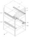
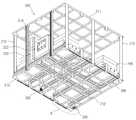
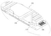
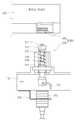
도 1은 본 발명의 일 실시예에 따른 카세트 보관 시스템에서 시스템 본체의 선반 영역을 보인 사시도이고, 도 2는 도 1에 도시된 선반에 클리닝 카세트가 안착된 상태의 사시도이며, 도 3은 클리닝 카세트의 사시도이고, 도 4는 도 3의 배면 사시도이며, 도 5는 도 3의 A 영역에 대한 확대도이고, 도 6은 도 4의 B 영역에 대한 확대도이며, 도 7은 충전 스테이션과 충전 단자 간의 배치 상태 사시도이고, 도 8은 충전 스테이션의 부분 절개 사시도이며, 도 9는 도 7의 측면도이고, 도 10은 충전 스테이션에 충전 단자가 접촉 가압된 도 9의 사용 상태 측면도이다.1 is a perspective view illustrating a shelf area of a system main body in a cassette storage system according to an embodiment of the present invention, FIG. 2 is a perspective view of a cleaning cassette seated on a shelf shown in FIG. 1, and FIG. 3 is a cleaning cassette. 4 is a rear perspective view of FIG. 3, FIG. 5 is an enlarged view of region A of FIG. 3, FIG. 6 is an enlarged view of region B of FIG. 4, and FIG. 7 is a charging station and a charging terminal. Fig. 8 is a partially cutaway perspective view of the charging station, Fig. 9 is a side view of Fig. 7, and Fig. 10 is a side view of the use state of Fig. 9 with the charging terminal pressed against the charging station.
이들 도면에 도시된 바와 같이, 본 실시예의 카세트 보관 시스템은, 다수의 기판(미도시)이 수납된 기판 수납용 카세트(C)가 안착 지지되는 다수의 선반(110) 을 구비하는 시스템 본체(100)와, 전원 유닛(220)을 구비하며 하단부의 적어도 일 영역이 선반(110)에 안착 지지되어 선반(110) 상의 파티클(particle)을 제거하는(cleaning) 클리닝 카세트(200)와, 적어도 어느 한 선반(110)과 클리닝 카세트(200)에 마련되며 해당 선반(110)에 클리닝 카세트(200)가 안착 지지될 때 전원 유닛(220)에 전기적으로 연결되어 전원 유닛(220)에 전원을 자동으로 충전시키는 전원 연결 유닛(300)을 포함한다.As shown in these figures, the cassette storage system of the present embodiment includes a system
시스템 본체(100)는, 본 실시예의 카세트 보관 시스템에서 클리닝 카세트(200)를 제외한 나머지 부분들의 전체를 가리킨다.The
따라서 시스템 본체(100)는 도 1 및 도 2에 도시된 단순 프레임 구조와는 달리 기판 수납용 카세트(C) 또는 클리닝 카세트(200)를 이송, 핸들링(handling)하는 카세트 스토커를 포함할 수 있다. 하지만, 본 실시예에서는 설명의 편의를 위해 선반(110)이 위치된 영역의 시스템 본체(100)의 일부 영역에 대해서만 도시하고 있다.Thus, unlike the simple frame structure illustrated in FIGS. 1 and 2, the system
이러한 시스템 본체(100)에는 다수의 선반(110)이 구비된다. 도 1 및 도 2에는 높이 방향을 따라 2개의 선반(110)만이 도시되어 있지만, 거대 구조물인 시스템 본체(100)에는 수 내지 수십 개 이상의 선반(110)이 구비될 수 있다.The
선반(110)의 원래 용도는 도 1에 도시된 바와 같이, 그 내부에 다수의 기판이 수납되는 다수의 슬롯(C1)을 구비한 기판 수납용 카세트(C)가 안착 지지되도록 하는 것이다.The original use of the
즉 앞서도 기술한 바와 같이, 다수의 기판이 수납된 기판 수납용 카세트(C) 는 어느 한 평판표시소자 제조 설비에서 해당 공정이 완료된 후 다음의 평판표시소자 제조 설비로 바로 이송되는 것이 아니라 평판표시소자 제조 설비들의 기판 처리 능력 및 시간의 차이에 의해 발생되는 버퍼링(buffering) 문제를 해소하기 위하여 시스템 본체(100)의 선반(110)에 임시로 보관되며(도 1의 점선 참조), 필요에 따라 도시 않은 카세트 스토커에 의해 해당 공정을 수행하는 평판표시소자 제조 설비로 이송된다.That is, as described above, the substrate receiving cassette C containing a plurality of substrates is not transferred directly to the next flat display device manufacturing facility after the corresponding process is completed in one flat display device manufacturing facility, but the flat panel display device. It is temporarily stored on the
다만, 카세트 스토커에 의해 기판 수납용 카세트(C)가 카세트 보관 시스템의 선반(110)에 적재되거나 반출되는 과정이 빈번하게 진행될 경우, 기판 수납용 카세트(C)가 안착 지지되는 선반(110)에는 파티클(particle)이 떨어져 잔존될 수 있으므로, 선반(110)에는 필요에 따라 클리닝 카세트(200) 역시 안착 지지될 수 있다.However, when the substrate storage cassette C is frequently loaded or taken out by the cassette stocker on the
도 2를 참조하면, 하부의 선반(110) 상에 파티클을 제거(클리닝, cleaning)하기 위해 이 위치의 선반(110)에 클리닝 카세트(200)가 안착 지지되는 도면을 도시하고 있다.Referring to FIG. 2, there is shown a view in which the
한편, 클리닝 카세트(200)는, 선반(110) 상에 잔존 가능한 파티클을 제거하기 위해, 기판 수납용 카세트(C) 대신에 해당 선반(110)에 안착 지지되는 구조물이다. 이러한 클리닝 카세트(200)는 기판 수납용 카세트(C)와 실질적으로 유사한 부피를 갖도록 제작된다.On the other hand, the
이처럼 클리닝 카세트(200)가 기판 수납용 카세트(C)와 실질적으로 유사한 부피를 가질 경우, 하나의 카세트 스토커를 이용하여 클리닝 카세트(200) 및 기판 수납용 카세트(C) 모두를 핸들링할 수 있어 경제적일 수 있다.As such, when the
파티클로 인한 공정 불량이 야기되지 않도록 선반(110) 상의 파티클을 제거하는 클리닝 카세트(200)는, 도 3 및 도 4에 도시된 바와 같이, 카세트 하우징(210)과, 카세트 하우징(210)의 일측에 결합되는 전원 유닛(220)과, 선반(110)에 접촉되는 카세트 하우징(210)의 하단부에 형성되는 진공 흡입 슬롯(230)과, 진공 흡입 슬롯(230)과 연결되며 전원 유닛(220)으로부터 인가된 전원에 의해 동작되면서 진공 흡입 슬롯(230)을 통해 선반(110) 상의 파티클 흡입을 위한 진공 흡입력을 발생시키는 다수의 흡입 유닛(240)을 구비한다.The cleaning
카세트 하우징(210)은 클리닝 카세트(200)의 외관을 형성하는 부분이다. 이러한 카세트 하우징(210)은, 격자 형상의 상부 프레임(211)과, 상부 프레임(211)의 하부 영역에서 상부 프레임(211)과 이격 배치되는 격자 형상의 하부 프레임(212)과, 상부 및 하부 프레임(211,212)을 연결하는 측부 프레임(213)을 구비한다.The cassette housing 210 is a part that forms an appearance of the cleaning
상부 및 하부 프레임(211,212)이 격자 형상을 이루고, 측부 프레임(213)이 상부 및 하부 프레임(211,212)을 군데군데에서 연결함으로써 카세트 하우징(210)의 전체 중량을 줄일 수 있는 이점이 있다.The upper and
하지만, 본 발명의 권리범위가 이에 제한될 필요는 없으므로 카세트 하우징(210)은 캐비닛 구조일 수도 있다. 다만, 카세트 하우징(210)이 캐비닛 구조를 갖더라도 충전 상태 표시용 시그널 타워(250, signal tower)를 관찰하기 위한 관찰창(미도시)은 구비되어야 할 것이다.However, since the scope of the present invention does not need to be limited thereto, the cassette housing 210 may have a cabinet structure. However, even if the cassette housing 210 has a cabinet structure, an observation window (not shown) for observing a
전원 유닛(220)은 클리닝 카세트(200)의 동작을 위한 전원을 공급하는 부분일 뿐만 아니라 전원 연결 유닛(300)과 전기적으로 연결되어 전원을 충전하는 부분 이기도 하다. 다시 말해, 전원 유닛(220)은 충전이 가능한 파워 서플라이(power supply)에 해당된다. 본 실시예에서 전원 유닛(220)은 충전 가능한 무정전 전원 유닛(UPS, Uninterruptible Power Supply)으로 적용되고 있다.The
전원 유닛(220)과 그 주변의 제어 박스(222) 등은 카세트 하우징(210)의 일측으로 치우쳐 배치되는데, 이들이 배치되는 카세트 하우징(210)에는 다른 곳에 비해 별도의 보강 프레임(214, 도 3 참조)이 더 구비된다. 따라서 무게를 지탱하기에 유리할 수 있다.The
이러한 전원 유닛(220)에는 늘 일정한 양 이상의 전원이 충전될 필요가 있다. 그래야만 클리닝 카세트(200)가 카세트 스토커에 의해 선반(110)을 옮겨 다니면서 선반(110) 상의 파티클을 연속적으로 제거할 수 있다.The
따라서 전원 유닛(220)에 전원이 어느 정도 충전되어 있는지의 여부를 외부로 표시할 필요가 있는데, 이를 위해 충전 상태 표시용 시그널 타워(250)가 마련된다.Therefore, it is necessary to display to the outside whether or not the power is charged to the
충전 상태 표시용 시그널 타워(250)는 카세트 하우징(210)에 마련되되 전원 유닛(220)과 연결되어 전원 유닛(220)의 충전 상태를 외부로 표시하는 역할을 하므로, 외부에서 보기가 좋은 위치에 마련되는 것이 바람직할 것이다.The
본 실시예의 경우, 충전 상태 표시용 시그널 타워(250)는 카세트 하우징(210)의 센터 영역에 상하로 길게 마련되어 외부의 어떠한 위치에서도 충전 상태 표시용 시그널 타워(250)를 용이하게 관찰할 수 있도록 하고 있다.In the present embodiment, the charge state
충전 상태 표시용 시그널 타워(250)는, 예컨대 그린(green, 충전상태 양호), 옐로(yellow, 보통), 레드(red, 충전 필요)로 표시될 수 있으며, 이러한 색상에 기초하여 전원 유닛(220)의 충전 여부가 결정될 수 있다.The
도 1 및 도 2와 같이, 선반(110)이 상호 나란한 한 쌍의 레일 타입(rail type)으로 마련되므로, 진공 흡입 슬롯(230)은 하부 프레임(212)을 이루는 4개의 변 중에서 상호 대향된 한 쌍의 변에 해당 변을 따라 길게 형성된다. 하지만, 본 발명의 권리범위가 이에 제한될 필요는 없다.1 and 2, since the
이러한 진공 흡입 슬롯(230)은 도 6에 도시된 바와 같이, 하부 프레임(212)의 밑면에서 하부 프레임(212)의 두께 방향을 따라 함몰된 형태의 홈이 하부 프레임(212)의 일측 변의 길이 방향을 따라 길게 형성된다.As shown in FIG. 6, the
이처럼 단순 홀(hole) 형태가 아닌 진공 흡입 슬롯(230)이 형성됨으로써 진공의 흡입력도 강해질 뿐만 아니라 선반(110)과의 접촉 면적을 줄일 수 있어 또 다른 파티클 발생을 원천적으로 차단할 수 있는 이점이 있다. 진공 흡입 슬롯(230)은 도시된 바와 같이 연속된 형태일 수도 있지만 군데군데 분할된 형태이어도 무방하다.As the
도시하고 있지는 않지만, 카세트 하우징(210)의 하부 프레임(212)에는 선반(110)의 바코드(bar code)를 판독하는 바코드 판독부(260, 도 3 참조)가 더 마련될 수 있다. 이처럼 바코드 판독부(260)가 마련될 경우, 다수의 선반(110)에 대한 클리닝 카세트(200)의 이송 위치 제어가 용이해지는 이점이 있다.Although not shown, the
흡입 유닛(240)은, 진공 흡입 슬롯(230)과 연결되며 전원 유닛(220)으로부터 인가된 전원에 의해 동작되면서 진공 흡입 슬롯(230)을 통해 선반(110) 상의 파티 클 흡입을 위한 진공 흡입력을 발생시키는 부분이다.The
본 실시예의 경우, 서로 이격된 위치에 4개의 흡입 유닛(240)이 개시되어 있는데, 이들 4개의 흡입 유닛(240)은 상부 및 하부 프레임(211,212) 내에서 하부 프레임(212) 상에 결합된다.In the present embodiment, four
흡입 유닛(240)들과 진공 흡입 슬롯(230)은 플렉시블(flexible)한 흡입 라인(241, 도 5 참조)에 의해 각각 연결된다. 본 실시예에서 흡입 유닛(240)들 각각에는 공기 정화용 필터(242)가 더 마련된다. 공기 정화용 필터(242)는 손쉽게 교체가 가능한 것이면 더욱 효과적일 것이다.The
한편, 기판 수납용 카세트(C)에 수납되는 기판은 가로/세로의 길이가 1.5 (m) 내외에 이르는 4~5 세대, 2 미터(m) 내외에 이르는 7~8 세대, 혹은 3 미터(m) 내외에 이르는 11 세대용 대면적 기판일 수 있다.On the other hand, the substrate accommodated in the substrate storage cassette C has 4 to 5 generations in which the length / length is about 1.5 (m), 7 to 8 generations or 2 meters (m), or 3 meters (m). It can be a large-area substrate for 11 generations, from inside to outside.
이러한 대면적 기판들이 수 내지 수십 장씩 수납되는 기판 수납용 카세트(C)는 부피가 큰 구조물이고, 기판 수납용 카세트(C)와 부피가 유사한 클리닝 카세트(200) 역시 부피가 큰 구조물(대략 120 kgf 정도 일 수 있음)이기 때문에, 기판 수납용 카세트(C) 또는 클리닝 카세트(200)가 안착 지지되는 다수의 선반(110)을 구비하는 시스템 본체(100)는 실질적으로 거대한 규모의 구조물일 수 있다.The substrate storage cassette C in which the large-area substrates are stored several to several tens is a bulky structure, and the cleaning
따라서 이러한 거대 구조물인 시스템 본체(100)에 마련되는 다수의 선반(110) 상의 파티클을 제거하는 작업이 수작업에 의해 수행되기는 어렵기 때문에 전술한 구조의 클리닝 카세트(200)를 이용하는 것이 바람직하다.Therefore, it is preferable to use the cleaning
하지만, 클리닝 카세트(200)를 이용하여 선반(110) 상의 파티클을 제거하더 라도 클리닝 카세트(200)에는 파티클 제거를 위한 전원이 공급되어야 하므로 클리닝 카세트(200)로의 전원 공급 문제가 적절하게 해결되지 않을 경우, 클리닝 카세트(200)의 활용도가 상당히 떨어질 수 있다.However, even when the particles on the
이러한 문제를 고려하여, 본 발명의 카세트 보관 시스템은, 적어도 어느 한 선반(110)과 클리닝 카세트(200)에 마련되며 해당 선반(110)에 클리닝 카세트(200)가 안착 지지될 때 전원 유닛(220)에 전기적으로 연결되어 전원 유닛(220)에 전원을 자동으로 충전시키는 전원 연결 유닛(300)을 구비하고 있는 것이다.In consideration of this problem, the cassette storage system of the present invention is provided on at least one
이러한 전원 연결 유닛(300)은, 다수의 선반(110) 중에서 적어도 어느 한 선반(110)에 마련되되 다수의 충전 핀(311)을 구비하는 충전 스테이션(310, 도 1 참조)과, 클리닝 카세트(200)에 마련되어 다수의 충전 핀(311)과 전기적으로 연결 가능한 충전 단자(330, 도 6 참조)를 구비한다.The
본 실시예의 경우, 충전 스테이션(310, 도 1 참조)은 선반(110)에, 그리고 충전 단자(330, 도 6 참조)는 클리닝 카세트(200)에 마련되고 있으나 반대의 경우도 가능하다. 하지만, 본 실시예와 같이, 충전 스테이션(310)이 선반(110)에 마련되는 경우가 보다 효과적일 수 있다.In the present embodiment, the charging station 310 (see FIG. 1) is provided on the
그리고 충전 단자(330)는 클리닝 카세트(200)마다 하나씩 마련되는 것이 바람직하나, 충전 스테이션(310)은 선반(110) 모두에 마련될 필요는 없다. 즉 선반(110)의 개수에 따라 달라질 수 있겠으나 수십개의 선반(110)이 구비된다면 이격된 위치의 한 곳 또는 두서너 곳의 선반(110)에 충전 스테이션(310)이 마련되면 그것으로 충분하다. 이는 충전 스테이션(310)이 계속해서 사용되는 것이 아니라 충전 시에만 사용되는 구성이기 때문이다.In addition, one charging
한편, 클리닝 카세트(200)의 충전 단자(330)가 선반(110)의 충전 스테이션(310)에 마련되는 충전 핀(311)에 가압 접촉되어 접점이 붙으면서 충전이 개시되거나 충전 완료 후 접점이 떨어질 때, 스파크(spark)의 발생 우려가 예상될 수 있는데, 스파크가 발생되면 기판에 손상을 주거나 작업자의 안전에 위협을 가할 수 있으므로 클리닝 카세트(200)의 충전 단자(330)가 선반(110)의 충전 핀(311)에 완전히 접촉했을 때에만 충전을 위한 전원이 인가되도록 하는 구조가 요구된다. 그래야만 스파크 발생을 근본적으로 차단할 수 있을 것이라 예상된다. 이를 위해 특히 충전 스테이션(310)은 다음의 구조를 갖는다.On the other hand, the charging
도 7 내지 도 10에 도시된 바와 같이, 충전 스테이션(310)은, 몸체부(312)와, 충전 핀(311)을 지지하되 몸체부(312) 내에서 충전 핀(311)과 함께 승하강 이동되는 핀 지지블록(313)과, 핀 지지블록(313)과 연결되어 충전 핀(311)의 승하강 이동 축선을 형성하는 샤프트(314)와, 샤프트(314)와 이격된 위치에서 샤프트(314)의 하부 영역에 마련되는 센서(315)와, 센서(315)와의 상호 작용에 의해 센서(315)가 충전을 위한 전기적인 접점 신호를 발생시키도록 하는 센서 도그(316, sensor dog)와, 샤프트(314)의 승하강 이동을 안내하는 엘엠 부시(318, LM bush)와, 탄성부재(319)를 구비한다.As shown in FIGS. 7 to 10, the charging
몸체부(312)는, 충전 스테이션(310)의 상부 외관을 형성하는 부분으로서 대략 사각 블록 구조를 가질 수 있다. 물론, 이는 하나의 실시예에 불과할 뿐 도시된 형상이 본 발명의 권리범위를 제한할 수는 없다.The
충전 핀(311)은, 클리닝 카세트(200)의 충전 단자(330)와 전기적으로 접촉되면서 전기 신호가 인가되는 부분이다. 충전 핀(311)과 충전 단자(330) 각각은 3개씩 마련된다. 참고로, 충전 단자(330)는 접점간 쇼트 방지를 위해 각 접점이 엠씨 나일론(MC-Nylon)으로 절연되어 보호되어 있으며, 실질적으로 충전 핀(311)과 접촉되는 부분은 통전이 용이한 재질로 제작된다.The charging
핀 지지블록(313)은, 3개의 충전 핀(311)을 하나의 몸체로 지지하는 구조체로서 충전 핀(311)과 함께 승하강 이동된다.The pin support block 313 moves up and down together with the charging pins 311 as a structure for supporting three charging
샤프트(314)는, 충전 핀(311)의 승하강 이동 축선을 형성하는 부분이다. 도 9와 같이 클리닝 카세트(200)가 올려지지 않으면 충전 핀(311) 및 핀 지지블록(313)과 함께 상향된 위치에 있다가, 도 10과 같이 클리닝 카세트(200)가 선반(110)에 올려지면서 클리닝 카세트(200)의 충전 단자(330)가 충전 핀(311)을 가압하면 충전 핀(311) 및 핀 지지블록(313)과 함께 하향된다. 샤프트(314)는 충전 핀(311)의 개수만큼 마련된다.The
센서(315)는, 충전을 위한 신호를 발생시키는 것으로서 본 실시예에서는 근접 센서(315)로 적용되고 있다. 근접 센서(315)의 감지 거리는 대략 0.1 ~ 5.6 mm일 수 있으므로 적어도 이 사이의 영역으로 센서 도그(317)가 근접되어야만 충전을 위한 전기적인 접점 신호가 발생되므로 충전에 안전을 보장할 수 있다. 센서(315)는 센서 브래킷(316, sensor bracket)에 의해 선반(110)의 적당한 위치에 고정될 수 있다.The
센서 도그(316)는, 샤프트(314)의 하단부에 결합되며, 클리닝 카세트(200)의 충전 단자(330)가 선반(110)의 충전 핀(311)에 접촉되어 클리닝 카세트(200)의 무게로 충전 핀(311)을 가압할 때 샤프트(314)와 함께 하향 이동되어 센서(315)와의 상호 작용에 의해 센서(315)가 충전을 위한 전기적인 접점 신호를 발생시키도록 하는 역할을 한다.The
앞서 기술한 센서(315)가 근접 센서이므로 도 10과 같이 센서 도그(316)가 하향되어 센서(315)와 대략 1.5 밀리미터(mm) 간격으로 근접될 경우, 충전을 위한 신호를 발생시키게 된다.Since the
이처럼 클리닝 카세트(200)의 충전 단자(330)가 선반(110)의 충전 스테이션(310)에 마련되는 충전 핀(311)에 접촉되는 정도만으로 충전이 진행되도록 하지 않고, 충전 단자(330)가 충전 핀(311)에 접촉된 후 클리닝 카세트(200)의 무게로 충전 핀(311)을 가압하여 센서 도그(316)가 센서(315)에 근접될 경우에 비로소 충전 신호가 발생되어 충전이 진행되도록 함으로써 스파크 발생을 근본적으로 차단할 수 있게 되며, 따라서 기판을 보호할 수 있고, 작업자의 안전을 보장할 수 있게 된다.As such, the charging
엘엠 부시(318)는, 샤프트(314)에 결합되어 샤프트(314)의 승하강 이동을 안내하는 역할을 한다.The
그리고 탄성부재(319)는 도 10과 같이 충전 핀(311)이 하향 가압된 상태에서 가압이 해제되면 도 9와 같이 충전 핀(311)이 원상태로 복귀될 수 있도록, 핀 지지블록(313)과 엘엠 부시(318)에 연결되어 충전 핀(311)이 원위치로 복귀되는 방향으로 탄성바이어스시키는 역할을 한다. 이러한 탄성부재(319)는 압축식 코일 스프링 으로 적용될 수 있다.And the
이러한 구조로 미루어 볼 때, 전원 연결 유닛(300)을 이루는 충전 단자(330), 충전 핀(311), 샤프트(314), 센서(315), 센서 도그(317) 및 탄성부재(319)는 3개씩 마련되고, 핀 지지블록(313)과 엘엠 부시(318)는 1개씩 마련될 수 있는데, 본 발명의 권리범위가 이의 개수 및 도면에 제한될 필요는 없다.In view of such a structure, the charging
이러한 구성을 갖는 카세트 보관 시스템의 작용에 대해 설명하면 다음과 같다.Referring to the operation of the cassette storage system having such a configuration as follows.
선반(110)에 대한 파티클 제거 작업, 다시 말해 선반(110)에 대한 클리닝(cleaning) 작업이 진행되면, 도시 않은 카세트 스토커가 클리닝 카세트(200)를 들어 클리닝 작업이 요구되는 선반(110)에 적재한다.When a particle removing operation on the
그러면 클리닝 카세트(200)의 하단부에 형성된 진공 흡입 슬릿(230)이 선반(110)에 안착 지지되다.Then, the vacuum suction slit 230 formed at the lower end of the cleaning
이 상태에서 전원 유닛(220)으로부터 전원이 인가되어 흡입 유닛(240)들이 동작되면 진공 흡입력이 발생됨으로써 선반(110) 상의 파티클은 진공 흡입 슬롯(230)을 통해 모아져 흡입된 후 흡입 라인(241, 도 5 참조)을 통해 흡입 유닛(240)으로 흡입된다. 이 경우, 입자 형태의 파티클은 흡입 유닛(240) 내에 저장되고 공기는 필터(242)를 통해 필터링된 후 외부로 방출된다.In this state, when power is applied from the
이러한 클리닝 작업은 필요한 선반(110)마다, 혹은 제어 프로그램에 의해 선반(110)들 순차적으로 진행됨으로써 모든 선반(110) 상의 파티클을 제거하게 된다.This cleaning operation is carried out sequentially for every
한편, 클리닝 작업 중에 충전 상태 표시용 시그널 타워(250)가 레드(red) 상 태로 바뀌면 클리닝 카세트(200)를 충전을 위한 지정된 선반(110)으로 이송시킨다. 충전을 위한 지정된 선반(110)으로 클리닝 카세트(200)를 이송시키는 작업 역시 카세트 스토커가 수행한다.On the other hand, when the charge state
카세트 스토커가 충전이 요구되는 클리닝 카세트(200)를 들어 지정된 선반(110), 다시 말해 충전 스테이션(310)이 장착되어 있는 선반(110)에 내려놓으면 클리닝 카세트(200)의 충전 단자(330)가 해당 선반(110)에 구비된 충전 핀(311)에 접촉되어 클리닝 카세트(200)의 무게로 충전 핀(311)을 가압하게 된다.When the cassette stocker picks up the cleaning
그러면 도 10과 같이 충전 핀(311)이 샤프트(314) 및 센서 도그(317)와 함께 하향 이동되고 센서 도그(317)가 근접 센서(315)로 접근됨에 따라 충전을 위한 전기적인 접점 신호가 발생되어 비로소 충전이 개시된다.Then, as shown in FIG. 10, as the charging
시간이 지나 충전이 완료되면 충전 상태 표시용 시그널 타워(250)는 충전이 완료되었음을 표시하는 그린(green) 색상으로 변하며, 그러면 카세트 스토커가 클리닝 카세트(200)를 들어 다시 다른 선반(110)의 클리닝 작업을 진행하게 된다.When charging is completed after time, the
이와 같이, 본 실시예에 따르면, 카세트 보관 시스템의 선반(110) 상에 잔존되는 파티클을 용이하게 제거할 수 있으며, 특히 동작을 위한 전원 공급을 간편하게 수행할 수 있게 된다.As such, according to the present embodiment, particles remaining on the
전술한 실시예의 경우, 클리닝 카세트(200)에 대한 선택적인 충전 방법을 설명하였으나 제어 프로그램에 의해 클리닝 카세트(200)는 예컨대 3시간 간격으로 충전될 수도 있을 것이다.In the above-described embodiment, an alternative charging method for the cleaning
이와 같이 본 발명은 기재된 실시예에 한정되는 것이 아니고, 본 발명의 사 상 및 범위를 벗어나지 않고 다양하게 수정 및 변형할 수 있음은 이 기술의 분야에서 통상의 지식을 가진 자에게 자명하다. 따라서 그러한 수정예 또는 변형예들은 본 발명의 특허청구범위에 속한다 하여야 할 것이다.As described above, the present invention is not limited to the described embodiments, and various modifications and changes can be made without departing from the spirit and scope of the present invention. It will be apparent to those skilled in the art. Therefore, such modifications or variations will have to be belong to the claims of the present invention.
도 1은 본 발명의 일 실시예에 따른 카세트 보관 시스템에서 시스템 본체의 선반 영역을 보인 사시도이다.1 is a perspective view showing the shelf area of the system body in the cassette storage system according to an embodiment of the present invention.
도 2는 도 1에 도시된 선반에 클리닝 카세트가 안착된 상태의 사시도이다.FIG. 2 is a perspective view of a cleaning cassette seated on a shelf shown in FIG. 1.
도 3은 클리닝 카세트의 사시도이다.3 is a perspective view of a cleaning cassette.
도 4는 도 3의 배면 사시도이다.4 is a rear perspective view of FIG. 3.
도 5는 도 3의 A 영역에 대한 확대도이다.FIG. 5 is an enlarged view of area A of FIG. 3.
도 6은 도 4의 B 영역에 대한 확대도이다.FIG. 6 is an enlarged view of region B of FIG. 4.
도 7은 충전 스테이션과 충전 단자 간의 배치 상태 사시도이다.7 is a perspective view of an arrangement state between a charging station and a charging terminal.
도 8은 충전 스테이션의 부분 절개 사시도이다.8 is a partially cutaway perspective view of the filling station.
도 9는 도 7의 측면도이다.9 is a side view of FIG. 7.
도 10은 충전 스테이션에 충전 단자가 접촉 가압된 도 9의 사용 상태 측면도이다.10 is a side view of the use state of FIG. 9 in which a charging terminal is pressed against a charging station.
* 도면의 주요 부분에 대한 부호의 설명* Explanation of symbols for the main parts of the drawings
100 : 시스템 본체 110 : 선반100: system body 110: shelf
200 : 클리닝 카세트 210 : 카세트 하우징200: cleaning cassette 210: cassette housing
220 : 전원 유닛 230 : 진공 흡입 슬롯220: power supply unit 230: vacuum suction slot
240 : 흡입 유닛 250 : 충전 상태 표시용 시그널 타워240: suction unit 250: signal tower for displaying the charging status
300 : 전원 연결 유닛 310 : 충전 스테이션300: power connection unit 310: charging station
311 : 충전 핀 312 : 몸체부311: charging pin 312: body
313 : 핀 지지블록 314 : 샤프트313 pin support block 314 shaft
315 : 센서 316 : 센서 브래킷315
317 : 센서 도그 318 : 엘엠 부시317: Sensor Dog 318: M Bush
319 : 탄성부재 330 : 충전 단자319: elastic member 330: charging terminal
Claims (18)
Translated fromKoreanPriority Applications (1)
| Application Number | Priority Date | Filing Date | Title |
|---|---|---|---|
| KR1020090044025AKR101042629B1 (en) | 2009-05-20 | 2009-05-20 | Cleaning cassettes and cassette storage systems having them |
Applications Claiming Priority (1)
| Application Number | Priority Date | Filing Date | Title |
|---|---|---|---|
| KR1020090044025AKR101042629B1 (en) | 2009-05-20 | 2009-05-20 | Cleaning cassettes and cassette storage systems having them |
Publications (2)
| Publication Number | Publication Date |
|---|---|
| KR20100125029Atrue KR20100125029A (en) | 2010-11-30 |
| KR101042629B1 KR101042629B1 (en) | 2011-06-20 |
Family
ID=43409002
Family Applications (1)
| Application Number | Title | Priority Date | Filing Date |
|---|---|---|---|
| KR1020090044025AExpired - Fee RelatedKR101042629B1 (en) | 2009-05-20 | 2009-05-20 | Cleaning cassettes and cassette storage systems having them |
Country Status (1)
| Country | Link |
|---|---|
| KR (1) | KR101042629B1 (en) |
Cited By (2)
| Publication number | Priority date | Publication date | Assignee | Title |
|---|---|---|---|---|
| KR101283409B1 (en)* | 2011-08-29 | 2013-07-08 | 크린팩토메이션 주식회사 | Cleaning cassette and cassette storage apparatus having the same |
| KR101444262B1 (en)* | 2013-10-01 | 2014-09-26 | 크린팩토메이션 주식회사 | Cleaning cassette |
Family Cites Families (3)
| Publication number | Priority date | Publication date | Assignee | Title |
|---|---|---|---|---|
| KR20060071015A (en)* | 2004-12-21 | 2006-06-26 | 삼성전자주식회사 | Cleaning device, storage device having same and cleaning method of storage device |
| KR100536434B1 (en) | 2004-12-30 | 2005-12-16 | 주식회사 에스에프에이 | System for keeping cassette |
| KR20080081692A (en)* | 2007-03-06 | 2008-09-10 | 엘지디스플레이 주식회사 | Stacker Robot for Cassette Transfer |
- 2009
- 2009-05-20KRKR1020090044025Apatent/KR101042629B1/ennot_activeExpired - Fee Related
Cited By (2)
| Publication number | Priority date | Publication date | Assignee | Title |
|---|---|---|---|---|
| KR101283409B1 (en)* | 2011-08-29 | 2013-07-08 | 크린팩토메이션 주식회사 | Cleaning cassette and cassette storage apparatus having the same |
| KR101444262B1 (en)* | 2013-10-01 | 2014-09-26 | 크린팩토메이션 주식회사 | Cleaning cassette |
Also Published As
| Publication number | Publication date |
|---|---|
| KR101042629B1 (en) | 2011-06-20 |
Similar Documents
| Publication | Publication Date | Title |
|---|---|---|
| JP4003882B2 (en) | Substrate transfer system | |
| TWI413610B (en) | Substrate transport facility | |
| CN101244887B (en) | glass input system | |
| TWI362083B (en) | Substrate processing apparatus | |
| KR101019534B1 (en) | Probe card stocker system | |
| EP2224499A1 (en) | Thin-film solar cell manufacturing system and common substrate storage rack | |
| CN101152919A (en) | Mask shell, mask box, pattern trasscription mehod and method for manufacturing display device | |
| KR20190009508A (en) | Die bonding apparatus | |
| KR102000079B1 (en) | Die bonding apparatus | |
| KR101042629B1 (en) | Cleaning cassettes and cassette storage systems having them | |
| CN110190013B (en) | Wafer loading device, wafer loading method and wafer cleaning equipment | |
| KR100829232B1 (en) | Handler for testing electronic components | |
| KR101640125B1 (en) | Apparatus for exchanging battery of automatic guided vehicle | |
| KR100478597B1 (en) | battery cell automatic provide machine | |
| CN109013365B (en) | Automatic detection equipment and detection system | |
| KR102401362B1 (en) | Die bonding apparatus | |
| JP2020155628A (en) | Tray transfer device and panel transfer system | |
| KR101108566B1 (en) | Stocker and stocker system | |
| CN219356996U (en) | Detection device and key production line | |
| JP4703089B2 (en) | Mounting board production equipment | |
| KR20110101623A (en) | Stacker Robot for Cassette Transfer | |
| KR101051283B1 (en) | Dumper and stocker system with it | |
| JP2004251641A (en) | Semiconductor wafer inspection apparatus and semiconductor wafer inspection method | |
| KR102104051B1 (en) | Device handler | |
| KR101283409B1 (en) | Cleaning cassette and cassette storage apparatus having the same |
Legal Events
| Date | Code | Title | Description |
|---|---|---|---|
| A201 | Request for examination | ||
| PA0109 | Patent application | St.27 status event code:A-0-1-A10-A12-nap-PA0109 | |
| PA0201 | Request for examination | St.27 status event code:A-1-2-D10-D11-exm-PA0201 | |
| D13-X000 | Search requested | St.27 status event code:A-1-2-D10-D13-srh-X000 | |
| D14-X000 | Search report completed | St.27 status event code:A-1-2-D10-D14-srh-X000 | |
| E902 | Notification of reason for refusal | ||
| PE0902 | Notice of grounds for rejection | St.27 status event code:A-1-2-D10-D21-exm-PE0902 | |
| PG1501 | Laying open of application | St.27 status event code:A-1-1-Q10-Q12-nap-PG1501 | |
| E13-X000 | Pre-grant limitation requested | St.27 status event code:A-2-3-E10-E13-lim-X000 | |
| P11-X000 | Amendment of application requested | St.27 status event code:A-2-2-P10-P11-nap-X000 | |
| P13-X000 | Application amended | St.27 status event code:A-2-2-P10-P13-nap-X000 | |
| E701 | Decision to grant or registration of patent right | ||
| PE0701 | Decision of registration | St.27 status event code:A-1-2-D10-D22-exm-PE0701 | |
| GRNT | Written decision to grant | ||
| PR0701 | Registration of establishment | St.27 status event code:A-2-4-F10-F11-exm-PR0701 | |
| PR1002 | Payment of registration fee | St.27 status event code:A-2-2-U10-U11-oth-PR1002 Fee payment year number:1 | |
| PG1601 | Publication of registration | St.27 status event code:A-4-4-Q10-Q13-nap-PG1601 | |
| R18-X000 | Changes to party contact information recorded | St.27 status event code:A-5-5-R10-R18-oth-X000 | |
| FPAY | Annual fee payment | Payment date:20140520 Year of fee payment:4 | |
| PR1001 | Payment of annual fee | St.27 status event code:A-4-4-U10-U11-oth-PR1001 Fee payment year number:4 | |
| PN2301 | Change of applicant | St.27 status event code:A-5-5-R10-R13-asn-PN2301 St.27 status event code:A-5-5-R10-R11-asn-PN2301 | |
| FPAY | Annual fee payment | Payment date:20150514 Year of fee payment:5 | |
| PR1001 | Payment of annual fee | St.27 status event code:A-4-4-U10-U11-oth-PR1001 Fee payment year number:5 | |
| FPAY | Annual fee payment | Payment date:20160517 Year of fee payment:6 | |
| PR1001 | Payment of annual fee | St.27 status event code:A-4-4-U10-U11-oth-PR1001 Fee payment year number:6 | |
| R18-X000 | Changes to party contact information recorded | St.27 status event code:A-5-5-R10-R18-oth-X000 | |
| P22-X000 | Classification modified | St.27 status event code:A-4-4-P10-P22-nap-X000 | |
| FPAY | Annual fee payment | Payment date:20170517 Year of fee payment:7 | |
| L13-X000 | Limitation or reissue of ip right requested | St.27 status event code:A-2-3-L10-L13-lim-X000 | |
| PR1001 | Payment of annual fee | St.27 status event code:A-4-4-U10-U11-oth-PR1001 Fee payment year number:7 | |
| U15-X000 | Partial renewal or maintenance fee paid modifying the ip right scope | St.27 status event code:A-4-4-U10-U15-oth-X000 | |
| PN2301 | Change of applicant | St.27 status event code:A-5-5-R10-R13-asn-PN2301 St.27 status event code:A-5-5-R10-R11-asn-PN2301 | |
| FPAY | Annual fee payment | Payment date:20180601 Year of fee payment:8 | |
| PR1001 | Payment of annual fee | St.27 status event code:A-4-4-U10-U11-oth-PR1001 Fee payment year number:8 | |
| FPAY | Annual fee payment | Payment date:20190401 Year of fee payment:9 | |
| PR1001 | Payment of annual fee | St.27 status event code:A-4-4-U10-U11-oth-PR1001 Fee payment year number:9 | |
| PC1903 | Unpaid annual fee | St.27 status event code:A-4-4-U10-U13-oth-PC1903 Not in force date:20200614 Payment event data comment text:Termination Category : DEFAULT_OF_REGISTRATION_FEE | |
| PC1903 | Unpaid annual fee | St.27 status event code:N-4-6-H10-H13-oth-PC1903 Ip right cessation event data comment text:Termination Category : DEFAULT_OF_REGISTRATION_FEE Not in force date:20200614 | |
| R18-X000 | Changes to party contact information recorded | St.27 status event code:A-5-5-R10-R18-oth-X000 |