KR20100121402A - Short profile optical connector - Google Patents
Short profile optical connectorDownload PDFInfo
- Publication number
- KR20100121402A KR20100121402AKR1020100019292AKR20100019292AKR20100121402AKR 20100121402 AKR20100121402 AKR 20100121402AKR 1020100019292 AKR1020100019292 AKR 1020100019292AKR 20100019292 AKR20100019292 AKR 20100019292AKR 20100121402 AKR20100121402 AKR 20100121402A
- Authority
- KR
- South Korea
- Prior art keywords
- connector
- cable
- bend
- fiber
- latch arm
- Prior art date
- Legal status (The legal status is an assumption and is not a legal conclusion. Google has not performed a legal analysis and makes no representation as to the accuracy of the status listed.)
- Withdrawn
Links
- 230000003287optical effectEffects0.000titleclaimsdescription21
- 239000000835fiberSubstances0.000claimsabstractdescription55
- 238000005452bendingMethods0.000claimsabstractdescription12
- 230000013011matingEffects0.000claimsdescription15
- 230000003014reinforcing effectEffects0.000claimsdescription7
- 230000000717retained effectEffects0.000claimsdescription2
- 238000000034methodMethods0.000claims19
- 230000008878couplingEffects0.000claims1
- 238000010168coupling processMethods0.000claims1
- 238000005859coupling reactionMethods0.000claims1
- 239000013307optical fiberSubstances0.000description9
- 230000002829reductive effectEffects0.000description6
- 230000006835compressionEffects0.000description3
- 238000007906compressionMethods0.000description3
- 239000000428dustSubstances0.000description3
- 230000004323axial lengthEffects0.000description2
- 238000003780insertionMethods0.000description2
- 230000037431insertionEffects0.000description2
- 238000012986modificationMethods0.000description2
- 230000004048modificationEffects0.000description2
- 230000002093peripheral effectEffects0.000description2
- OKTJSMMVPCPJKN-UHFFFAOYSA-NCarbonChemical compound[C]OKTJSMMVPCPJKN-UHFFFAOYSA-N0.000description1
- 229920006099Vestamid®Polymers0.000description1
- 230000002411adverseEffects0.000description1
- 238000013459approachMethods0.000description1
- 238000004891communicationMethods0.000description1
- 230000001010compromised effectEffects0.000description1
- 238000002788crimpingMethods0.000description1
- 238000000586desensitisationMethods0.000description1
- 238000011161developmentMethods0.000description1
- 230000018109developmental processEffects0.000description1
- 239000011152fibreglassSubstances0.000description1
- 230000009970fire resistant effectEffects0.000description1
- 230000000670limiting effectEffects0.000description1
- 230000007774longtermEffects0.000description1
- 229920000642polymerPolymers0.000description1
- 230000001681protective effectEffects0.000description1
- 230000002787reinforcementEffects0.000description1
Images

Classifications
- G—PHYSICS
- G02—OPTICS
- G02B—OPTICAL ELEMENTS, SYSTEMS OR APPARATUS
- G02B6/00—Light guides; Structural details of arrangements comprising light guides and other optical elements, e.g. couplings
- G02B6/24—Coupling light guides
- G02B6/36—Mechanical coupling means
- G02B6/38—Mechanical coupling means having fibre to fibre mating means
- G02B6/3807—Dismountable connectors, i.e. comprising plugs
- G02B6/381—Dismountable connectors, i.e. comprising plugs of the ferrule type, e.g. fibre ends embedded in ferrules, connecting a pair of fibres
- G02B6/3826—Dismountable connectors, i.e. comprising plugs of the ferrule type, e.g. fibre ends embedded in ferrules, connecting a pair of fibres characterised by form or shape
- G02B6/3829—Bent or angled connectors
- G—PHYSICS
- G02—OPTICS
- G02B—OPTICAL ELEMENTS, SYSTEMS OR APPARATUS
- G02B6/00—Light guides; Structural details of arrangements comprising light guides and other optical elements, e.g. couplings
- G02B6/24—Coupling light guides
- G02B6/36—Mechanical coupling means
- G02B6/38—Mechanical coupling means having fibre to fibre mating means
- G02B6/3807—Dismountable connectors, i.e. comprising plugs
- G02B6/381—Dismountable connectors, i.e. comprising plugs of the ferrule type, e.g. fibre ends embedded in ferrules, connecting a pair of fibres
- G02B6/3818—Dismountable connectors, i.e. comprising plugs of the ferrule type, e.g. fibre ends embedded in ferrules, connecting a pair of fibres of a low-reflection-loss type
- G02B6/3821—Dismountable connectors, i.e. comprising plugs of the ferrule type, e.g. fibre ends embedded in ferrules, connecting a pair of fibres of a low-reflection-loss type with axial spring biasing or loading means
- G—PHYSICS
- G02—OPTICS
- G02B—OPTICAL ELEMENTS, SYSTEMS OR APPARATUS
- G02B6/00—Light guides; Structural details of arrangements comprising light guides and other optical elements, e.g. couplings
- G02B6/24—Coupling light guides
- G02B6/36—Mechanical coupling means
- G02B6/38—Mechanical coupling means having fibre to fibre mating means
- G02B6/3807—Dismountable connectors, i.e. comprising plugs
- G02B6/3833—Details of mounting fibres in ferrules; Assembly methods; Manufacture
- G02B6/3847—Details of mounting fibres in ferrules; Assembly methods; Manufacture with means preventing fibre end damage, e.g. recessed fibre surfaces
- G02B6/3849—Details of mounting fibres in ferrules; Assembly methods; Manufacture with means preventing fibre end damage, e.g. recessed fibre surfaces using mechanical protective elements, e.g. caps, hoods, sealing membranes
- G—PHYSICS
- G02—OPTICS
- G02B—OPTICAL ELEMENTS, SYSTEMS OR APPARATUS
- G02B6/00—Light guides; Structural details of arrangements comprising light guides and other optical elements, e.g. couplings
- G02B6/24—Coupling light guides
- G02B6/36—Mechanical coupling means
- G02B6/38—Mechanical coupling means having fibre to fibre mating means
- G02B6/3807—Dismountable connectors, i.e. comprising plugs
- G02B6/3887—Anchoring optical cables to connector housings, e.g. strain relief features
- G02B6/38875—Protection from bending or twisting
- G—PHYSICS
- G02—OPTICS
- G02B—OPTICAL ELEMENTS, SYSTEMS OR APPARATUS
- G02B6/00—Light guides; Structural details of arrangements comprising light guides and other optical elements, e.g. couplings
- G02B6/24—Coupling light guides
- G02B6/36—Mechanical coupling means
- G02B6/38—Mechanical coupling means having fibre to fibre mating means
- G02B6/3807—Dismountable connectors, i.e. comprising plugs
- G02B6/389—Dismountable connectors, i.e. comprising plugs characterised by the method of fastening connecting plugs and sockets, e.g. screw- or nut-lock, snap-in, bayonet type
- G02B6/3893—Push-pull type, e.g. snap-in, push-on
Landscapes
- Physics & Mathematics (AREA)
- General Physics & Mathematics (AREA)
- Optics & Photonics (AREA)
- Mechanical Coupling Of Light Guides (AREA)
- Light Guides In General And Applications Therefor (AREA)
Abstract
Translated fromKoreanDescription
Translated fromKorean본 발명은 통신 및 정보 시스템들에 사용되는 케이블들을 종결시키기 위한 커넥터들, 특히, 파이버 광학 케이블용 커넥터들에 관한 것이다.The present invention relates to connectors for terminating cables used in communication and information systems, in particular connectors for fiber optical cables.
네트워크 시스템 관리자는 새롭고 더 복잡한 다기능 플러그인 모듈을 수용하기 위해, 현장에서 장비 캐비닛들 내부의 가용 공간을 확장시켜야할 필요가 있는 경우가 많다. 모듈들은 주 패널 뒤쪽에서 캐비닛 내측의 프레임 상에 장착되도록 구성된다. 이러한 추가 공간은 주 패널을 캐비닛 상의 전방 도어에 더 가깝게 재배치하여, 캐비닛 도어 뒤쪽과 패널 사이의 공간을 감소시킴으로써 얻어지는 것이 일반적이다. 그러나, 패널과 도어 사이의 공간은 모듈들의 전방면에서 종결되는 다수의 네트워크 케이블들에 의해 점유되어 있다. 따라서, 이러한 공간을 어떻게 감소시키든지, 케이블들을 과도하게 굴곡시키거나 캐비닛 내측의 다른 공간에서 소위 교차 연결부들(cross connects)을 형성하지 않으면서 모듈들의 바로 전방에서 케이블들을 종결시키기가 어려워진다.Network system administrators often need to expand the available space inside the equipment cabinets in the field to accommodate new and more complex multifunction plug-in modules. The modules are configured to be mounted on a frame inside the cabinet behind the main panel. This additional space is typically achieved by rearranging the main panel closer to the front door on the cabinet, thereby reducing the space between the back of the cabinet door and the panel. However, the space between the panel and the door is occupied by a number of network cables which terminate at the front side of the modules. Thus, reducing this space, it becomes difficult to terminate the cables directly in front of the modules without excessively bending the cables or forming so-called cross connects in other spaces inside the cabinet.
전기 케이블들은 케이블들의 성능에 부정적인 영향 없이, 모듈들 상의 그들의 정합 커넥터들에 관하여 급격한 90° 굴곡부를 형성하는 커넥터들에서 종결될 수 있다. 즉, 전기 케이블들은 케이블들을 매우 큰 정도로 굴곡시키지 않고, 케이블들이 종결되는 그 모듈들에 인접하게 라우팅될 수 있다. 그러나, 광 파이버들은 영구적 손상 없이는 지정된 최소 굴곡 반경보다 작게 굴곡될 수 없다. 대부분의 광 파이버들을 위한 최소 굴곡 반경은 약 1 인치(in)이다. 과거에, 모듈들의 전방에 남겨지는 개방 캐비닛 공간의 깊이는 케이블들 내의 파이버들의 최소 굴곡 반경을 위배하지 않으면서 광 케이블들을 라우팅 및 종결하기에 충분하였다. 그러나, 상술한 바와 같이, 이 공간의 깊이는 더 새로운 교체 모듈들을 위한 공간을 마련하기 위해 감소되는 경우가 빈번하다.Electrical cables can be terminated in connectors forming a sharp 90 ° bend with respect to their mating connectors on the modules, without adversely affecting the performance of the cables. That is, the electrical cables can be routed adjacent to those modules where the cables terminate, without bending the cables to a very large extent. However, optical fibers cannot be bent less than the specified minimum bend radius without permanent damage. The minimum bend radius for most optical fibers is about 1 inch. In the past, the depth of the open cabinet space left in front of the modules was sufficient to route and terminate the optical cables without violating the minimum bending radius of the fibers in the cables. However, as mentioned above, the depth of this space is often reduced to make room for newer replacement modules.
연계된 커넥터 부근의 광 파이버에 부적절한 응력이 유발되면, 삽입 손실이 증가하기 쉽다. 손실은, 종종 파이버가 수납되는 케이블 또는 코드(cordage) 상의 축외(off-axis) 인장 부하의 결과로서 커넥터의 후방으로부터 파이버가 빠져나오는 지점에서, 또는 그 부근에서 파이버가 굴곡될 때 발생한다. 대부분의 광학 케이블 커넥터들은 커넥터의 후방에 뻣뻣한 케이블 보유 요소들을 포함하며, 케이블 내측에서 축방향으로 연장하는 코드형 케이블 보강 부재들은 보강 부재들의 단부 길이들을 보유 요소들 내에 크림핑함으로써 보유된다. 축방향 인장 부하에 대해 적절한 고정을 제공하지만, 보유 요소들은 케이블이 보유 요소들 부근에서 굴곡되는 경우 광 파이버에 손실 문제를 유발할 수 있다. 따라서, 파이버를 위한 최소 굴곡 반경을 유의하면서, 커넥터의 후방에 축외 인장 부하를 견디도록 파이버에 필요한 지지부를 제공하는 것이 어려운 것으로 판명되었다.If an improper stress is induced in the optical fiber near the associated connector, insertion loss is likely to increase. Loss often occurs when the fiber is bent at or near the point where the fiber exits from the rear of the connector as a result of an off-axis tensile load on the cable or cordage on which the fiber is received. Most optical cable connectors include stiff cable retaining elements at the rear of the connector, and corded cable reinforcing members extending axially inside the cable are retained by crimping the end lengths of the reinforcing members into the retaining elements. While providing adequate fixation against axial tensile loads, the retaining elements can cause loss problems in the optical fiber if the cable is bent near the retaining elements. Thus, it has proved difficult to provide the necessary support for the fiber to withstand the off-axis tensile load at the rear of the connector, taking note of the minimum bending radius for the fiber.
통상적으로 커넥터의 후방에 제공되는 직선 케이블 굴곡 제한기들 또는 변형율 경감 부트들(strain relief boots)을 최소 굴곡 반경을 보전하면서 커넥터의 후방에 근접하게 45°또는 90°케이블 굴곡부를 제공하도록 성형된 사전 굴곡된 부트들로 교체함으로써, 광학 케이블 커넥터의 전체 길이가 감소되어 왔다. 또한, 가요성 굴곡 제한 부트들이 광학 케이블 커넥터들의 후방에서 보다 일정한 45°또는 90°케이블 굴곡부들을 형성하게 하도록 성형된 클립들이 사용되어왔다.Preforms molded to provide 45 ° or 90 ° cable bends in close proximity to the connector while preserving the minimum bend radius, typically with straight cable bend limiters or strain relief boots provided at the back of the connector. By replacing with curved boots, the overall length of the optical cable connector has been reduced. In addition, clips have been used that have been shaped to allow flexible bend limiting boots to form more constant 45 ° or 90 ° cable bends at the rear of the optical cable connectors.
다른 공지된 접근법은 부트를 직선형으로 유지하지만, 그 길이를 단축시켜 파이버가 커넥터의 후방에 더 근접하게 굴곡부가 시작될 수 있게 하는 것이다. 소위 쇼트 부트 LC 및 SC 광학 커넥터는 미국 조지아주 노크로스 소재의 OFS Fitel LLC 및 기타 제조처(source)들로부터 상업적으로 입수할 수 있다. 케이블은 통상적 LC 쇼트 부트 커넥터의 전방 팁으로부터 약 42.4 mm의 거리에서, 그리고, 전형적인 SC 쇼트 부트 커넥터에서 약 52.0 mm의 거리에서 시작하여 굴곡부가 개시될 수 있다. 개괄적으로, US 특허 제5,347,603호(1994.9.13), 제5,390,272호(1995.2.14), 제6,629,783호(2003.10.7) 및 제7,001,081호(2006.2.21)를 참조하라.Another known approach is to keep the boot straight, but shorten its length so that the fiber can bend closer to the rear of the connector. So-called Short Boot LC and SC optical connectors are commercially available from OFS Fitel LLC and other sources, Norcross, GA. The cable can be started at a distance of about 42.4 mm from the front tip of a conventional LC short boot connector, and at a distance of about 52.0 mm from a typical SC short boot connector. In general, see US Pat. Nos. 5,347,603 (1994.9.13), 5,390,272 (1995.2.14), 6,629,783 (2003.10.7) and 7,001,081 (2006.2.21).
다른 해법은 모듈들의 전면판에 커넥터 어댑터를 설치하는 것을 포함하며, 여기서, 어댑터는 파이버 광학 케이블이 어댑터에 대한 연결을 위해 90°굴곡부가 아닌 45°굴곡부만을 형성하는 것을 필요로 한다. 그러나, 이런 어댑터를 사용하는 모듈 전면판은 이를 위해 종종 모듈 내부에 더 많은 필요 공간을 대가로 한다. 모듈 회로 보드의 복잡성 증가와 함께, 캐비닛 내측에 45°경사로 장착되도록 배열된 어댑터 또는 소위 작은 형상 인자(SFF)의 트랜스시버 모듈을 사용하는 것은 감소되어 왔다.Another solution involves installing a connector adapter in the faceplate of the modules, where the adapter requires the fiber optic cable to form only 45 ° bends rather than 90 ° bends for connection to the adapter. However, module faceplates using such adapters often cost more space inside the module for this purpose. With the increasing complexity of the module circuit boards, the use of adapters or so-called small form factor (SFF) transceiver modules arranged to mount 45 ° inclined inside the cabinet has been reduced.
US 특허 출원 공개 제2008/0240657호(2008.10.2)는 하나 이상의 직각 굴곡부들을 형성하는 내부 영역을 갖는 강체 페룰 형태의 직각 광 파이버 커넥터 조립체를 개시한다. 소위 굴곡 기능성 파이버들(bend performance fibers)은 페룰의 각 단부에서 커넥터들 사이의 내부 영역을 횡단하고, 이 파이버들은 직각 굴곡부에서 내부 영역의 것보다 작은 최소 굴곡 반경을 갖는다.US Patent Application Publication No. 2008/0240657 (2008.10.2) discloses a right angle optical fiber connector assembly in the form of a rigid ferrule having an inner region forming one or more right angle bends. So-called bend performance fibers traverse the inner region between the connectors at each end of the ferrule, which fibers have a minimum bending radius that is smaller than that of the inner region at right angles.
굴곡 내성 또는 굴곡 둔감성 파이버들(BIF)이라고도 지칭되는 굴곡 기능성 파이버들은 미국 특허 제7,257,293호(2007.8.14) 및 미국 특허 출원 공개 제2007/0104437호(2007.5.10), 제2008/0166094호(2008.7.10) 및 제2009/0060437호(2009.3.5)에 개시되어 있다. 마지막에 언급한 공보에 개시된 바와 같이 제조된 파이버들은 4 mm 만큼 작은 최소 굴곡 반경을 나타내며, EZ Bend®라는 상표명 하에 미국 조지아주 노크로스 소재의 OFS Fitel, LLC로부터 입수할 수 있고, 다른 상업적 제조처들로부터도 입수할 수 있다.Flexural functional fibers, also referred to as flex resisting or flexing insensitive fibers (BIF), are described in US Patent Nos. 7,257,293 (2007.8.14) and US Patent Application Publication Nos. 2007/0104437 (2007.5.10), 2008/0166094 (2008.7) .10) and 2009/0060437 (2009.3.5). Fibers prepared as disclosed in the last mentioned publication exhibit a minimum bending radius as small as 4 mm and are available from OFS Fitel, LLC, Norcross, GA, under the tradename EZ Bend® , and other commercial manufacturers. It is available from these, too.
본 발명의 커넥터 구조는 케이블 라우팅을 위해 작은 공간이 가용 상태로 남아 있는 캐비닛 내에 설치된 장비에서, 그 성능이 훼손되는 범위까지 케이블들을 굴곡시키지 않고 광 파이버 케이블들을 종결할 수 있게 한다.The connector structure of the present invention makes it possible to terminate optical fiber cables without bending the cables to the extent that their performance is compromised in equipment installed in a cabinet where a small space remains available for cable routing.
본 발명에 따라서, 광학 케이블 커넥터 구조는 축과, 전방 단부와 후방 단부를 갖는 커넥터 하우징을 포함한다. 칼라를 포함하는 요크가 하우징과 축방향으로 정렬되어 커넥터 하우징의 후방 단부에 결합된다. 관형 케이블 굴곡 제한기는 일 단부가 칼라에 고정되고, 굴곡 제한기는 파이버가 1 인치(25.4 mm) 미만의 굴곡 반경을 취득하도록 굴곡 제한기의 대향 단부와 칼라 사이의 지정된 굴곡부를 통해, 적어도 하나의 굴곡 둔감성 파이버를 포함하는 케이블을 안내하도록 치수설정 및 형성된다.According to the invention, the optical cable connector structure comprises a connector housing having an axis, a front end and a rear end. A yoke comprising a collar is axially aligned with the housing and coupled to the rear end of the connector housing. The tubular cable bend limiter has one end fixed to the collar, and the bend limiter has at least one bend through the designated bend between the collar and the opposite end of the bend limiter such that the fiber acquires a bend radius of less than 1 inch (25.4 mm). It is dimensioned and shaped to guide a cable comprising insensitive fiber.
본 발명의 더 양호한 이해를 위해, 첨부 도면 및 첨부 청구범위에 연계하여 이루어지는 하기의 상세한 설명을 참조한다.For a better understanding of the invention, reference is made to the following detailed description taken in conjunction with the accompanying drawings and the appended claims.
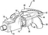
도 1은 본 발명에 따른 조립된 파이버 광학 케이블의 사시도.
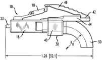
도 2는 도 1의 좌측의 먼지 덮개가 제거된, 도 1의 커넥터의 측면도.
도 3은 구성요소들이 조립되는 순서 및 커넥터의 구성요소들을 예시하는 도 1의 케이블 커넥터의 분해도.
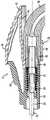
도 4는 도 1의 커넥터를 단면으로 도시하는 확대 측면도.
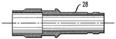
도 5는 커넥터의 구성요소 보강 부재를 단면으로 도시하는 측면도.1 is a perspective view of an assembled fiber optics cable according to the invention.
2 is a side view of the connector of FIG. 1 with the dust cover on the left side of FIG. 1 removed;
3 is an exploded view of the cable connector of FIG. 1 illustrating the order in which the components are assembled and the components of the connector;
4 is an enlarged side view showing the connector of FIG. 1 in cross section;
5 is a side view showing in cross section the component reinforcing members of the connector;
측정가능한 손실의 증가 없이, 5 mm 반경 내의 최소 굴곡 반경을 갖는 굴곡 둔감성 파이버들(BIF)의 개발은 파이버들이 통상적 광학 케이블들에 비해 더 급격한 굴곡부를 형성하도록 수용되는 케이블들을 가능하게 한다. 비록, BIF가 급격한 굴곡부에 의해 유발되는 응력을 받을 수 있지만, 파이버의 삽입 손실의 대응하는 증가는 존재하지 않는다. 따라서, BIF를 위한 최소 허용 굴곡 반경은 주로 파이버 글래스의 장기 신뢰성에 기초하며, 굴곡부의 응력하에 있을 때의 파이버의 광학적 성능에 기초하지 않는다.Without increasing the measurable loss, the development of flexural insensitive fibers (BIF) with a minimum bending radius within a 5 mm radius enables the cables to be accommodated so that the fibers form a more rapid bend compared to conventional optical cables. Although BIF may be subjected to stress caused by a sharp bend, there is no corresponding increase in insertion loss of the fiber. Thus, the minimum allowable bend radius for BIF is primarily based on the long-term reliability of the fiberglass and not the optical performance of the fiber when under the stress of the bend.
기본적으로, 본 발명의 케이블 커넥터는 크게 감소된 전체 길이의 커넥터 본체와, 커넥터의 후방에 고정된 1 인치 미만의 굴곡 반경으로 형성된 강체 케이블 굴곡 제한기 또는 부트를 특징으로 한다. 현재 예시된 실시예에서, 부트는 90°의 케이블 굴곡부를 형성한다. 커넥터 뒤쪽에서의 굴곡 이후 부트로부터 케이블이 빠져나오는 지점은 커넥터의 전방 팁으로부터 단지 약 1.26 인치(32.1 mm)의 거리에 있다. 이 거리는 케이블이 커넥터 뒤에서 빠져나오면서 어떤 상태에서든 굴곡부가 개시되는 지점의 매우 앞쪽의 종래의 광학 케이블 커넥터 상의 지점에 대응한다. 따라서, 굴곡 둔감성 파이버를 수용하는 케이블이 본 발명의 커넥터 내에서 종결되는 경우, 커넥터 호환성 및 성능을 위한 모든 적용가능한 표준을 여전히 충족시키면서 캐비닛 또는 임의의 장소에서 모듈 어댑터 또는 SFF 트랜스시버의 전방에서 케이블과 커넥터에 의해 점유되는 공간은 30%까지 감소될 수 있다.Basically, the cable connector of the present invention features a greatly reduced full length connector body and a rigid cable flex limiter or boot formed with a bend radius of less than 1 inch fixed to the rear of the connector. In the presently illustrated embodiment, the boot forms a 90 ° cable bend. The cable exit from the boot after bending behind the connector is only about 1.26 inches (32.1 mm) from the front tip of the connector. This distance corresponds to the point on the conventional optical cable connector very forward of the point where the bend is initiated in any state as the cable exits behind the connector. Thus, when a cable receiving flexural insensitive fiber is terminated within the connector of the present invention, the cable and the cable in front of the module adapter or SFF transceiver in the cabinet or anywhere are still meeting all applicable standards for connector compatibility and performance. The space occupied by the connector can be reduced by 30%.
도 1은 본 발명에 따른 파이버 광학 케이블 커넥터(10)의 사시도이다. 도 2는 도 1의 좌측에 있는 보호 먼지 덮개(14)가 제거되어 커넥터의 전방 팁을 노출시킨 이후의 커넥터(10)의 측면도이다. 도 3은 그 별개의 구성요소들과, 구성요소들이 서로 조립되는 순서를 도시하는 커넥터(10)의 분해도이다. 비록, 본 명세서에서 LC형 커넥터로서 설명하지만, 본 기술 분야의 숙련자들은 본 발명의 커넥터가 예로서, SC 및 ST 커넥터를 포함하는 광학 케이블 커넥터의 다른 유형들에 적용가능한 모든 요구조건들에 부합하도록 치수설정될 수 있다는 것을 이해할 것이다.1 is a perspective view of a fiber
도 3에서 좌상부로부터 진행하면서, 커넥터(10)는 상술한 먼지 덮개(14)를 구비할 수 있으며, 이는 통상적으로 길이가 약 0.775 인치(19.68 mm)인 종래의 LC 커넥터들의 하우징보다 매우 더 짧은 약 0.538 인치(13.67 mm)의 전체 길이(LH)를 갖는 하우징(16)을 포함한다. 로크/해제 래치 아암(18)은 하우징의 전방을 향해 하우징(16)의 상부측에 일 단부에서 고정되고, 아암(18)은 커넥터의 후방을 향해 상향 경사진다. 래치 아암(18)은 커넥터가 정합 어댑터 내로 삽입될 때 커넥터(10)를 적소에 로크하거나, 아암(18)이 눌러질 때 정합 어댑터로부터 커넥터(10)를 해제하도록 공지된 방식으로 작동한다.Proceeding from the upper left in FIG. 3, the
또한, 커넥터(10)는 커넥터 하우징(16) 내측에서 축방향으로 연장하도록 지지된 페룰 배럴(22)을 가지며, 연계된 압축 스프링(24)은 커넥터가 조립되고 나서 페룰 배럴에 전향 축방향 편향력을 인가하도록 페룰 배럴(22)의 후방부 위로 동축으로 배치된다. 페룰 배럴(22) 및 스프링(24) 양자 모두는 종래의 방식으로 형성 및 치수설정되고, 페룰 배럴(22)의 전방 팁(23)이 하우징(16)의 전방 단부의 개구 밖으로 돌출하도록 커넥터 하우징(16) 내측에 배열된다. 본 기술 분야에 공지된 바와 같이, 페룰 배럴(22)은 페룰 배럴 내에 축방향 통로를 통해 삽입된 광학 파이버를 보유하도록, 그리고, 파이버의 연마된 단부면을 제공하도록 기능하며, 연마된 단부면에서, 파이버가 정합 커넥터 내의 다른 파이버와 광학적으로 결합할 수 있게 하도록 전방 팁(23)에서 통로가 개방된다.In addition, the
도 4 및 도 5에 단면으로 도시되어 있는, 도 3에 도시된 대체로 원통형 보유 부재(28)는 케이블의 보강 부재를 고정하여 커넥터(10)에 의해 종결되도록 부분적으로 기능한다. 또한, 보유 부재(28)는 종래의 광학 케이블 커넥터에 제공된 유사한 보유 부재들 또는 요소들보다 훨씬 더 짧으며, 본 실시예에서, 단지 약 0.500 인치(12.70 mm)의 전체 축방향 길이만을 갖는다. 부재(28)는 축방향 후방 부분(30)과, 축방향 전방 부분(32)을 갖는다. 후방 부분(30)은 부재(28) 내측의 종결된 케이블의 단부 길이의 통로를 허용하도록 예로서, 0.092 인치(2.34 mm)의 내경을 가지며 케이블 보강 부재들의 단부들은 주변 크림프 슬리브(34)에 의해 그 위에 크림핑 되도록 후방 부분(30)의 외주 상에 배치된다. 보유 부재(28)의 전방 부분(32)은 페룰 배럴(22)의 후방 부분 및 압축 스프링(24)의 후방 부분을 수용하기 위해 예로서, 0.120 인치(3.05 mm)의 더 큰 내경을 가지며, 압축 스프링은 그 전방 부분(32)과 후방 부분(30) 사이의 계면에서 보유 부재(28)의 내측에 형성된 환형 단차부에 대해 올려놓아진다. 보유 부재(28)의 중간 섹션은 그 외주 상에 환형 돌기 또는 링을 가지며, 따라서, 부재(28)가 커넥터 하우징(16)의 후방에 삽입되고 스프링(24)이 압축될 때, 링은 하우징 내에 형성된 정합 오목부 내에 배치되고, 부재(28)를 스프링(24)의 힘에 대항하여 적소에 보유한다.The generally cylindrical retaining
요크(38)는 칼라(40) 및 조립된 커넥터(10)의 후방으로 연장하는 트리거부(42)를 갖도록 형성된다. 칼라(40)는 약 0.226 인치(5.74 mm)의 축방향 길이를 가지며, 약 0.200 인치(5.08 mm)의 내경을 갖는다. 트리거부(42)는 칼라 축에 실질적으로 평행하게 외팔보 형태로 칼라(40)의 상부로부터 후향 돌출하는 베이스 플랜지(44)와, 조립시 래치 아암(18)과 접촉하여 커넥터(10)의 전방을 향해 래치 아암(18)을 누르도록 플랜지(44)의 후방 단부로부터 상향 경사진 핑거부(46, finger)를 포함한다. 칼라(40)와 외팔보형 트리거부(42)를 포함하는 요크(38)의 전체 길이는 약 0.650 인치(16.51 mm)이다.The
요크(38) 및 커넥터 하우징(16)은 하우징(16)의 후방부 내측과 요크의 칼라(40) 내측으로 그 부분들이 연장하는 보유 부재(28)에 의해 서로 접촉하도록 결합된다. 도 4 참조. 따라서, 하우징(16)의 전방 단부로부터 요크의 트리거부(42)의 후방 단부까지 측정된 커넥터(10)의 길이는 단지 약 0.538 인치 + 0.650 인치 = 1.188 인치(30.18 mm)이다.The
강체 튜브 형태의 케이블 굴곡 제한기(50)는 일 단부에서 도 4에 도시된 바와 같이, 칼라(40)의 내주에 억지끼워맞춤 또는 다른 방식으로 부착된다. 종결된 케이블의 통로를 허용하는 것에 추가하여, 칼라(40)와 결합하는 위치의 제한기(50)의 내경은 주변 크림프 슬리브(34)로 보유 부재(28)의 후방 부분(30)을 수용하기에 충분하다. 본 명세서에서 굴곡 제한기(50)의 형태를 설명하기 위해 사용될 때, 용어 "관" 또는 "관형"은 그 단면이 원통형 이외의 것일 수 있으며, 그 벽들이 제한기(50)의 외주 둘레에 완전히 근접하지 않을 수 있는 중공 구조체들을 포함한다.The
본 실시예에서, 케이블 굴곡 제한기(50)는 제한기의 대향 단부와 칼라(40) 바로 뒤의 지점 사이에서 커넥터 축에 관하여 90°굴곡부를 통해 케이블을 안내하도록 형성된다. 바람직하게는, 굴곡 제한기(50)는 굴곡 둔감성 유형의 파이버를 가정하면, 케이블 굴곡부 전부는 아닐지라도 대부분에 대해 1 인치 미만의 케이블 파이버를 위한 굴곡 반경(RB)을 얻도록 치수설정된다. 예로서, 굴곡 제한기(50)가 90°케이블 굴곡부에 걸쳐 0.300 인치(7.62 mm)의 안전 파이버 굴곡 반경을 얻는 경우, 페룰 배럴(22)의 전방 팁(23)과 굴곡부 이후의 케이블 표면 상의 가장 먼 지점 사이의 축방향 거리는 1.26 인치(32 mm) 만큼 작을 수 있다. 굴곡 제한기가 90°케이블 굴곡부에 걸쳐 0.600 인치(15.24 mm)의 안전 파이버 굴곡 반경을 얻는 경우, 페룰 배럴의 전방 팁(23)과 케이블 표면 사이의 가장 먼 축방향 거리는 여전히 단지 약 1.35 인치(34.3 mm)이다.In this embodiment, the
일 실시예에서, 케이블 굴곡 제한기(50)는 예로서, Evonik Degussa GmbH로부터 입수할 수 있는 Vestamid®X7166 같은 강성적이지만 가공가능하면서 내화성인 폴리머로 성형될 수 있다. 굴곡 제한기(50)는 보유 부재(28)의 후방 부분(30)과 케이블의 외부 재킷 둘레에 근접하도록, 그리고, 맨드릴 또는 다른 종래의 공구의 사용에 의해 케이블이 원하는 굴곡 반경이 된 이후 서로 래치(latch)하도록 구성 및 치수설정된 두 개의 반부들 내에서 성형될 수 있다. 다른 실시예에서, 가장 좁은 슬롯이 축방향으로 굴곡 제한기(50)가 벽 내에 형성될 수 있으며, 따라서, 케이블이 슬롯을 통해 측방향으로 케이블을 압박함으로써 제한기 내측에 배치될 수 있다. 1.6 mm의 외경을 갖는 케이블에 대하여, 굴곡 제한기(50) 내의 통로의 내경은 바람직하게는 약 1.7 mm이며, 제한기의 벽 두께는 바람직하게는 약 1.0 mm 내지 1.5 mm의 범위이다.In one embodiment, the
전술한 바와 같이, 본 발명은 굴곡 둔감 특성을 가지는 단일 모드 또는 다중 모드 광 파이버들을 구비한, LC형 이외의 광학 커넥터들에서 실현될 수 있다. 본 발명의 커넥터는 그들의 시스템이 더 감소된 공간에서 파이버 광학 케이블링을 사용함으로써 서로 연결될 수 있게 하는 더 짧은 커넥터 해결책에 대한 주요 네트워크 설비들의 구매 인력 및 엔지니어들에 의한 현재의 요구를 충족시킨다.As mentioned above, the present invention can be realized in optical connectors other than LC type, with single mode or multi mode optical fibers having flexural desensitization characteristics. The connector of the present invention meets the current needs by the purchasing staff and engineers of major network facilities for shorter connector solutions that allow their systems to be connected to each other by using fiber optic cabling in a reduced space.
상술한 설명이 본 발명의 양호한 실시예들을 보여주지만, 본 기술의 숙련자들은 본 발명의 개념 및 범주로부터 벗어나지 않고, 다양한 변용들 및 변경들을 달성할 수 있다는 것을 이해할 수 있을 것이다. 이런 변용들은 광학 파이버들의 평면형 어레이(즉, 리본) 형태로 파이버 광학 케이블을 수용하도록 치수설정 및 형성된 광학 케이블 커넥터를 포함하지만 이에 한정되지는 않는다. 따라서, 본 발명은 하기의 청구범위 내에서 이루어지는 모든 이런 변용들 및 변경들을 포함한다.
While the foregoing description shows preferred embodiments of the present invention, those skilled in the art will appreciate that various changes and modifications can be made without departing from the spirit and scope of the present invention. Such variations include, but are not limited to, optical cable connectors dimensioned and configured to receive fiber optical cables in the form of a planar array of optical fibers (ie, ribbons). Accordingly, the present invention includes all such modifications and variations as come within the scope of the following claims.
Claims (20)
Translated fromKorean축과, 전방 단부와, 후방 단부를 갖는 커넥터 하우징과;
상기 하우징과 축방향으로 정렬되며 상기 커넥터 하우징의 후방 단부에 결합되는 칼라를 포함하는 요크와; 및
일 단부가 상기 칼라에 고정된 관형 케이블 굴곡 제한기를 포함하고,
상기 굴곡 제한기는 파이버가 1 인치(25.4 mm) 미만의 굴곡 반경을 취득하도록 상기 굴곡 제한기의 대향 단부와 상기 칼라 사이에서 지정된 굴곡부를 통해 적어도 하나의 굴곡 둔감성 파이버를 포함하는 케이블을 안내하도록 치수설정 및 형성되는 것을 특징으로 하는 광학 케이블 커넥터 조립체.An optical cable connector assembly,
A connector housing having a shaft, a front end, and a rear end;
A yoke axially aligned with the housing and including a collar coupled to a rear end of the connector housing; And
One end includes a tubular cable bend limiter secured to the collar,
The bend limiter is dimensioned to guide the cable including at least one bend insensitive fiber through a bend designated between the opposite end of the bend limiter and the collar such that the fiber acquires a bend radius of less than 1 inch (25.4 mm). And an optical cable connector assembly formed.
상기 굴곡 제한기는 상기 굴곡 제한기의 대향 단부와 상기 칼라 사이에 약 90°의 굴곡부를 통해 케이블을 안내하도록 형성되는 케이블 커넥터 조립체.The method of claim 1,
And the flexure restrictor is configured to guide the cable through a 90 ° bend between the opposite end of the flexure restrictor and the collar.
상기 굴곡 제한기는 약 0.300 인치(7.62 mm)와 약 0.600 인치(15.24 mm) 사이의 파이버 곡률 반경을 생성하도록 구성되는 케이블 커넥터 조립체.The method of claim 2,
Wherein the flex limiter is configured to produce a fiber radius of curvature between about 0.300 inch (7.62 mm) and about 0.600 inch (15.24 mm).
상기 요크의 최후방 단부와 상기 커넥터 하우징의 전방 단부 사이의 커넥터 길이는 약 1.188 인치(30.18 mm) 이하인 케이블 커넥터 조립체.The method of claim 1,
The connector length between the rearmost end of the yoke and the front end of the connector housing is about 1.188 inches (30.18 mm) or less.
(a) 상기 커넥터 하우징은 래치 아암이 눌러질 때 정합 커넥터에 커넥터를 로킹하거나 정합 커넥터로부터 커넥터를 분리하기 위해 연계된 로크/해제 래치 아암을 구비하고,
(b) 상기 요크는 (i) 상기 커넥터 하우징으로부터 멀어지는 후방 방향으로 외팔보 형태로 상기 칼라로부터 돌출하는 베이스 플랜지와, (ii) 상기 커넥터 하우징 상의 래치 아암과 접촉하여 상기 래치 아암을 누르기 위해 상기 플랜지의 후방 단부로부터 상향 경사진 핑거부를 포함하는 트리거부를 갖는 케이블 커넥터 조립체.The method of claim 1,
(a) the connector housing has an associated lock / release latch arm for locking the connector to the mating connector or detaching the connector from the mating connector when the latch arm is pressed;
(b) the yoke includes (i) a base flange protruding from the collar in the form of a cantilever in a rearward direction away from the connector housing, and (ii) contacting the latch arm on the connector housing to press the latch arm. A cable connector assembly having a trigger portion comprising a finger portion inclined upwardly from the rear end.
적어도 하나의 굴곡 둔감성 파이버를 포함하는 소정 길이의 광학 케이블과; 및
축방향으로 상기 커넥터 하우징 내측으로 연장하도록 지지된 페룰 배럴로서, 상기 페룰 배럴은 축방향 관통 통로를 가지며, 상기 축방향 관통 통로는 통로 내에 상기 굴곡 둔감성 파이버를 보유하도록 그리고 상기 파이버의 단부면을 제공하도록 형성되며, 상기 파이버가 정합 커넥터 내의 다른 파이버와 결합할 수 있게 하도록 상기 배럴의 전방 팁에서 통로가 개방되는, 상기 페룰 배럴과,
상기 케이블 내에 수용된 상기 굴곡 둔감성 파이버는 상기 굴곡 제한기 내측에서 1 인치(25.4 mm) 미만의 곡률 반경을 취득하는 것을 특징으로 하는 케이블 커넥터 조립체.The method of claim 1,
An optical cable of predetermined length comprising at least one curved insensitive fiber; And
A ferrule barrel supported to extend into the connector housing in an axial direction, the ferrule barrel having an axial through passage, the axial through passage retaining the curved insensitive fiber in the passage and providing an end face of the fiber The ferrule barrel, wherein the ferrule barrel is configured to open a passage at the front tip of the barrel to allow the fiber to engage another fiber in the mating connector;
Wherein the flexural insensitive fiber received in the cable acquires a radius of curvature of less than 1 inch (25.4 mm) inside the flex limiter.
상기 케이블은 상기 굴곡 제한기 내측에서 약 90° 굴곡부를 통해 안내되는 케이블 커넥터 조립체.The method according to claim 6,
And the cable is guided through an approximately 90 ° bend inside the bend limiter.
상기 케이블 내에 수용된 상기 굴곡 둔감성 파이버는 상기 굴곡 제한기 내측에서 약 0.300 인치(7.62 mm) 내지 약 0.600 인치(15.24 mm) 사이의 곡률 반경을 취득하는 케이블 커넥터 조립체.The method of claim 7, wherein
And the flexural insensitive fiber received within the cable acquires a radius of curvature between about 0.300 inches (7.62 mm) and about 0.600 inches (15.24 mm) inside the flex limiter.
상기 커넥터 하우징의 전방 단부와 상기 요크의 최후방 단부 사이의 커넥터의 길이는 약 1.188 인치(30.18 mm) 이하인 케이블 커넥터 조립체.The method according to claim 6,
A cable connector assembly, wherein the length of the connector between the front end of the connector housing and the rear end of the yoke is about 1.188 inches (30.18 mm) or less.
(a) 상기 커넥터 하우징은 상기 래치 아암이 눌러질 때 정합 커넥터에 상기 커넥터를 로킹하거나 상기 정합 커넥터로부터 상기 커넥터를 해제하기 위해 연계된 래치 아암을 가지며,
(b) 상기 요크는 (i) 상기 커넥터 하우징으로부터 멀어지는 후방 방향으로 외팔보 형태로 상기 칼라로부터 돌출하는 베이스 플랜지와, (ii) 상기 커넥터 하우징 상의 래치 아암과 접촉하여 상기 래치 아암을 누르기 위해 상기 플랜지의 후방 단부로부터 상향 경사진 핑거부를 포함하는 트리거부를 갖는 케이블 커넥터 조립체.The method according to claim 6,
(a) the connector housing has an associated latch arm for locking the connector to the mating connector or releasing the connector from the mating connector when the latch arm is pressed;
(b) the yoke includes (i) a base flange protruding from the collar in the form of a cantilever in a rearward direction away from the connector housing, and (ii) contacting the latch arm on the connector housing to press the latch arm. A cable connector assembly having a trigger portion comprising a finger portion inclined upwardly from the rear end.
상기 커넥터에 의해 종결될 케이블의 보강 부재들을 보유하도록 구성 및 배열된 관형 보유 부재로서, 상기 관형 보유 부재의 대응 부분들이 상기 요크의 칼라 내측으로, 그리고, 상기 하우징의 후방부 내측으로 연장하여 상기 요크와 상기 하우징을 서로 축방향으로 정렬된 상태로 결합하는, 상기 관형 보유 부재; 및
적어도 일부가 상기 커넥터 하우징의 축방향으로 보유 부재 내측에 지지되는 페룰 배럴으로서, 상기 페룰 배럴은 축방향 관통 통로를 가지며, 상기 축방향 관통 통로는 통로 내에 케이블 파이버를 보유하도록 그리고 파이버의 단부면을 제공하도록 형성되며, 상기 파이버가 상기 정합 커넥터 내의 다른 파이버와 결합할 수 있도록 상기 페룰 배럴의 전방 팁에서 통로가 개방되는, 상기 페룰 배럴을 특징으로 하는 케이블 커넥터 조립체.The method of claim 1,
A tubular retaining member constructed and arranged to hold reinforcing members of a cable to be terminated by the connector, wherein corresponding portions of the tubular retaining member extend inside the collar of the yoke and inside the rear portion of the housing to extend the yoke. The tubular retaining member coupling the housing and the housing in an axially aligned state with each other; And
A ferrule barrel at least partially supported inside the retaining member in the axial direction of the connector housing, the ferrule barrel having an axial through passage, the axial through passage retaining the cable fiber in the passage and end faces of the fiber. And the ferrule barrel, wherein the passage is open at the front tip of the ferrule barrel so that the fiber can engage other fibers in the mating connector.
상기 굴곡 제한기는 상기 굴곡 제한기의 대향 단부와 상기 칼라 사이의 약 90°굴곡부를 통해 상기 케이블을 안내하도록 형성되는 케이블 커넥터 조립체.The method of claim 11,
And the bend restrictor is configured to guide the cable through an approximately 90 ° bend between the opposite end of the bend limiter and the collar.
상기 굴곡 제한기는 약 0.300 인치(7.62 mm)와 약 0.600 인치(15.24 mm) 사이의 파이버 곡률 반경을 생성하도록 구성되는 케이블 커넥터 조립체.The method of claim 12,
Wherein the flex limiter is configured to produce a fiber radius of curvature between about 0.300 inch (7.62 mm) and about 0.600 inch (15.24 mm).
상기 요크의 최후방 단부와 상기 커넥터 하우징의 전방 단부 사이의 커넥터 길이는 약 1.188 인치(30.18 mm) 이하인 케이블 커넥터 조립체.The method of claim 11,
The connector length between the rearmost end of the yoke and the front end of the connector housing is about 1.188 inches (30.18 mm) or less.
(a) 상기 커넥터 하우징은 상기 래치 아암이 눌러질 때 정합 어댑터에 상기 커넥터를 로킹하거나 상기 정합 어댑터로부터 상기 커넥터를 분리하기 위해 연계된 래치 아암을 구비하고,
(b) 상기 요크는 (i) 상기 커넥터 하우징으로부터 멀어지는 후방 방향으로 외팔보 형태로 상기 칼라로부터 돌출하는 베이스 플랜지와, (ii) 상기 커넥터 하우징 상의 상기 래치 아암과 접촉하여 상기 래치 아암을 누르기 위해 상기 플랜지의 후방 단부로부터 상향 경사진 핑거부를 포함하는 트리거부를 갖는 케이블 커넥터 조립체.The method of claim 11,
(a) the connector housing has an associated latch arm for locking the connector to or mating the connector from the mating adapter when the latch arm is pressed;
(b) the yoke includes (i) a base flange protruding from the collar in the form of a cantilever in a rearward direction away from the connector housing, and (ii) the flange for contacting the latch arm on the connector housing to press the latch arm. And a trigger portion comprising a finger portion inclined upwardly from the rear end of the cable connector assembly.
소정 길이의 광학 케이블이 적어도 하나의 굴곡 둔감성 파이버를 수용하며, 상기 케이블은 연계된 보강 부재들을 가지며,
상기 관형 보유 부재는 상기 케이블의 상기 보강 부재들을 보유하고,
상기 케이블 내에 수용된 상기 굴곡 둔감성 파이버는 상기 페룰 배럴 내의 축방향 관통 통로 내에 보유되며,
상기 케이블 내에 수용된 상기 굴곡 둔감성 파이버는 상기 굴곡 제한기 내측에서 1 인치(25.4 mm) 미만의 굴곡 반경을 취득하는 것을 특징으로 하는 케이블 커넥터 조립체.The method of claim 11,
An optical cable of a predetermined length receives at least one curved insensitive fiber, the cable having associated reinforcing members,
The tubular retaining member retains the reinforcing members of the cable,
The curved insensitive fiber received in the cable is retained in an axial through passage in the ferrule barrel,
And the flexural insensitive fiber received in the cable acquires a flexure radius of less than 1 inch (25.4 mm) inside the flex limiter.
상기 케이블은 상기 굴곡 제한기 내측에서 약 90°의 굴곡부를 통해 안내되는 케이블 커넥터 조립체.17. The method of claim 16,
And the cable is guided through a bend of about 90 ° inside the bend limiter.
상기 케이블 내에 수용된 상기 굴곡 둔감성 파이버는 상기 굴곡 제한기 내측에서 약 0.300 인치(7.62 mm)와 약 0.600 in(15.24 mm) 사이의 굴곡 반경을 취득하는 케이블 커넥터 조립체.The method of claim 17,
And the flexural insensitive fiber received within the cable acquires a bending radius between about 0.300 inch (7.62 mm) and about 0.600 in (15.24 mm) inside the flex limiter.
상기 커넥터 하우징의 전방 단부와 상기 요크의 최후방 단부 사이의 커넥터의 길이는 약 1.188 인치(30.18 mm) 이하인 케이블 커넥터 조립체.17. The method of claim 16,
A cable connector assembly, wherein the length of the connector between the front end of the connector housing and the rear end of the yoke is about 1.188 inches (30.18 mm) or less.
(a) 상기 커넥터 하우징은 상기 래치 아암이 눌러질 때 정합 어댑터에 상기 커넥터를 로킹하거나 상기 정합 어댑터로부터 상기 커넥터를 분리하기 위해 연계된 래치 아암을 구비하고,
(b) 상기 요크는 (i) 상기 커넥터 하우징으로부터 멀어지는 후방 방향으로 외팔보 형태로 상기 칼라로부터 돌출하는 베이스 플랜지와, (ii) 상기 커넥터 하우징 상의 래치 아암과 접촉하여 상기 래치 아암을 누르기 위해 상기 플랜지의 후방 단부로부터 상향 경사진 핑거부를 포함하는 트리거부를 갖는 케이블 커넥터 조립체.
17. The method of claim 16,
(a) the connector housing has an associated latch arm for locking the connector to or mating the connector from the mating adapter when the latch arm is pressed;
(b) the yoke includes (i) a base flange protruding from the collar in the form of a cantilever in a rearward direction away from the connector housing, and (ii) contacting the latch arm on the connector housing to press the latch arm. A cable connector assembly having a trigger portion comprising a finger portion inclined upwardly from the rear end.
Applications Claiming Priority (4)
| Application Number | Priority Date | Filing Date | Title |
|---|---|---|---|
| US17624409P | 2009-05-07 | 2009-05-07 | |
| US61/176,244 | 2009-05-07 | ||
| US12/584,758US20100284656A1 (en) | 2009-05-07 | 2009-09-11 | Short profile optical connector |
| US12/584,758 | 2009-09-11 |
Publications (1)
| Publication Number | Publication Date |
|---|---|
| KR20100121402Atrue KR20100121402A (en) | 2010-11-17 |
Family
ID=42238284
Family Applications (1)
| Application Number | Title | Priority Date | Filing Date |
|---|---|---|---|
| KR1020100019292AWithdrawnKR20100121402A (en) | 2009-05-07 | 2010-03-04 | Short profile optical connector |
Country Status (5)
| Country | Link |
|---|---|
| US (1) | US20100284656A1 (en) |
| EP (1) | EP2249190A3 (en) |
| JP (1) | JP2010262298A (en) |
| KR (1) | KR20100121402A (en) |
| CN (1) | CN101881864A (en) |
Families Citing this family (41)
| Publication number | Priority date | Publication date | Assignee | Title |
|---|---|---|---|---|
| DK2664951T3 (en)* | 2008-05-07 | 2016-09-19 | Huber + Suhner Ag | Plug connector with unlocking |
| WO2013052070A1 (en) | 2011-10-05 | 2013-04-11 | Senko Advanced Components, Inc. | Latching connector with remote release |
| JP2015511334A (en)* | 2012-02-21 | 2015-04-16 | コーニング オプティカル コミュニケーションズ リミテッド ライアビリティ カンパニー | Structure and method for thermal management in an active optical cable (AOC) assembly |
| US8899845B2 (en) | 2012-05-15 | 2014-12-02 | Panduit Corp. | Fiber optic connector |
| US9417400B2 (en)* | 2012-05-24 | 2016-08-16 | Ofs Fitel, Llc | Short optical connector for cables containing a bend insensitive fiber |
| CN103576246B (en)* | 2012-08-03 | 2015-06-10 | 鸿富锦精密工业(深圳)有限公司 | Optical fiber connector |
| JP6068881B2 (en)* | 2012-09-04 | 2017-01-25 | 矢崎総業株式会社 | Optical connector |
| CN103176245B (en)* | 2013-03-06 | 2016-05-18 | 中航光电科技股份有限公司 | A kind of small-sized LC plug |
| US9658409B2 (en) | 2015-03-03 | 2017-05-23 | Senko Advanced Components, Inc. | Optical fiber connector with changeable polarity |
| GB2538089B (en)* | 2015-05-06 | 2019-06-19 | Fibrefab Ltd | Fibre optic cable assembly |
| CN105140719B (en)* | 2015-05-27 | 2018-08-10 | 中航光电科技股份有限公司 | Pull the optical connector and electric connector of unlock |
| USD830304S1 (en)* | 2015-06-23 | 2018-10-09 | A. J. World Co., Ltd. | Optical connector for optical fiber |
| US10158194B2 (en) | 2016-01-15 | 2018-12-18 | Senko Advanced Components, Inc. | Narrow width adapters and connectors with spring loaded remote release |
| JP2017207594A (en)* | 2016-05-17 | 2017-11-24 | エヌ・ティ・ティ・コミュニケーションズ株式会社 | Optical cable, and insertion/removal method |
| US9726830B1 (en) | 2016-06-28 | 2017-08-08 | Senko Advanced Components, Inc. | Connector and adapter system for two-fiber mechanical transfer type ferrule |
| US10228521B2 (en) | 2016-12-05 | 2019-03-12 | Senko Advanced Components, Inc. | Narrow width adapters and connectors with modular latching arm |
| US10185100B2 (en)* | 2017-01-30 | 2019-01-22 | Senko Advanced Components, Inc | Modular connector and adapter assembly using a removable anchor device |
| US10444444B2 (en) | 2017-01-30 | 2019-10-15 | Senko Advanced Components, Inc. | Remote release tab connector assembly |
| US9989712B1 (en) | 2017-03-20 | 2018-06-05 | Senko Advanced Components, Inc | MPO connector assembly with push-pull tab |
| US10718910B2 (en) | 2017-05-03 | 2020-07-21 | Senko Advanced Components, Inc | Field terminated ruggedized fiber optic connector system |
| US11822133B2 (en) | 2017-07-14 | 2023-11-21 | Senko Advanced Components, Inc. | Ultra-small form factor optical connector and adapter |
| US10281669B2 (en) | 2017-07-14 | 2019-05-07 | Senko Advance Components, Inc. | Ultra-small form factor optical connectors |
| US12001064B2 (en) | 2017-07-14 | 2024-06-04 | Senko Advanced Components, Inc. | Small form factor fiber optic connector with multi-purpose boot |
| US10718911B2 (en) | 2017-08-24 | 2020-07-21 | Senko Advanced Components, Inc. | Ultra-small form factor optical connectors using a push-pull boot receptacle release |
| US11002923B2 (en) | 2017-11-21 | 2021-05-11 | Senko Advanced Components, Inc. | Fiber optic connector with cable boot release having a two-piece clip assembly |
| US11016250B2 (en)* | 2017-12-19 | 2021-05-25 | Us Conec, Ltd. | Mini duplex connector with push-pull polarity mechanism, carrier, and rail-receiving crimp body |
| WO2019183070A2 (en) | 2018-03-19 | 2019-09-26 | Senko Advanced Components, Inc. | Removal tool for removing a plural of micro optical connectors from an adapter interface |
| EP3776038B1 (en) | 2018-03-28 | 2024-07-03 | Senko Advanced Components Inc. | Small form factor fiber optic connector with multi-purpose boot |
| USD897959S1 (en)* | 2018-04-06 | 2020-10-06 | Huber+Suhner Ag | Connecting plug for a fiber optic cable end |
| CN112088327A (en) | 2018-07-15 | 2020-12-15 | 扇港元器件股份有限公司 | Subminiature Optical Connectors and Adapters |
| US11073664B2 (en) | 2018-08-13 | 2021-07-27 | Senko Advanced Components, Inc. | Cable boot assembly for releasing fiber optic connector from a receptacle |
| US10921530B2 (en) | 2018-09-12 | 2021-02-16 | Senko Advanced Components, Inc. | LC type connector with push/pull assembly for releasing connector from a receptacle using a cable boot |
| WO2020055440A1 (en) | 2018-09-12 | 2020-03-19 | Senko Advanced Componetns, Inc. | Lc type connector with clip-on push/pull tab for releasing connector from a receptacle using a cable boot |
| US10921531B2 (en) | 2018-09-12 | 2021-02-16 | Senko Advanced Components, Inc. | LC type connector with push/pull assembly for releasing connector from a receptacle using a cable boot |
| US11806831B2 (en) | 2018-11-21 | 2023-11-07 | Senko Advanced Components, Inc. | Fixture and method for polishing fiber optic connector ferrules |
| US11175464B2 (en) | 2018-11-25 | 2021-11-16 | Senko Advanced Components, Inc. | Open ended spring body for use in an optical fiber connector |
| US12038613B2 (en) | 2019-03-28 | 2024-07-16 | Senko Advanced Components, Inc. | Behind-the-wall optical connector and assembly of the same |
| US11579379B2 (en) | 2019-03-28 | 2023-02-14 | Senko Advanced Components, Inc. | Fiber optic adapter assembly |
| US11340406B2 (en) | 2019-04-19 | 2022-05-24 | Senko Advanced Components, Inc. | Small form factor fiber optic connector with resilient latching mechanism for securing within a hook-less receptacle |
| WO2020252355A1 (en) | 2019-06-13 | 2020-12-17 | Senko Advanced Components, Inc | Lever actuated latch arm for releasing a fiber optic connector from a receptacle port and method of use |
| CN114600018B (en) | 2019-07-23 | 2024-04-09 | 扇港元器件有限公司 | Ultra-small receptacle for receiving a fiber optic connector opposite a ferrule assembly |
Family Cites Families (29)
| Publication number | Priority date | Publication date | Assignee | Title |
|---|---|---|---|---|
| US5287425A (en)* | 1993-02-26 | 1994-02-15 | Foxconn International, Inc. | Optical fiber SC type connector assembly with partly pre-assembled components |
| US5347603A (en)* | 1993-06-14 | 1994-09-13 | Molex Incorporated | Right angle cable strain relief |
| US5390272A (en)* | 1993-08-31 | 1995-02-14 | Amphenol Corporation | Fiber optic cable connector with strain relief boot |
| US5481634A (en)* | 1994-06-24 | 1996-01-02 | At&T Corp. | Connector for optical fiber |
| US5461690A (en)* | 1994-07-29 | 1995-10-24 | At&T Ipm Corp. | Bend-limiting apparatus for a cable |
| US5710851A (en)* | 1995-11-06 | 1998-01-20 | Amphenol Corporation | Strain relief system for a fiber optic connector |
| US6024498A (en)* | 1998-02-05 | 2000-02-15 | Lucent Technologies Inc. | Optical fiber connector assembly |
| US6017153A (en)* | 1998-05-29 | 2000-01-25 | Lucent Technologies, Inc. | Optical fiber connector with auxiliary spring |
| JP2000258658A (en)* | 1999-03-09 | 2000-09-22 | Sony Corp | Plastic optical fiber connector |
| US6155146A (en)* | 1999-07-28 | 2000-12-05 | Lucent Technologies Inc. | Optical fiber connector tuning wrench |
| US6287018B1 (en)* | 1999-07-28 | 2001-09-11 | Lucent Technologies Inc. | Tunable optical fiber connector |
| GB2354339B (en)* | 1999-09-16 | 2003-02-19 | Yazaki Corp | Optic fibre plug receptacle having moulded core and body |
| US6293710B1 (en)* | 1999-10-06 | 2001-09-25 | Lucent Technologies Inc. | Optical connector having a one-piece housing |
| JP3361785B2 (en)* | 1999-11-12 | 2003-01-07 | セイコーインスツルメンツ株式会社 | Optical connector assembly |
| US6554489B2 (en)* | 2001-03-28 | 2003-04-29 | Corning Cable Systems Llc | Fiber optic cable guide and method of application |
| JP2002341182A (en)* | 2001-05-14 | 2002-11-27 | Auto Network Gijutsu Kenkyusho:Kk | Optical connector |
| US7490997B2 (en)* | 2001-06-12 | 2009-02-17 | Robert Verhagen | Integrated bend limiter for fiber optic connectors |
| US6629783B2 (en)* | 2001-07-06 | 2003-10-07 | Fci Americas Technology, Inc. | Fiber optic cable guide boot |
| US6883974B2 (en)* | 2003-02-21 | 2005-04-26 | Itt Manufacturing Enterprises, Inc. | Optic fiber connector with spring in a self-contained cartridge |
| US7001081B2 (en)* | 2003-05-22 | 2006-02-21 | 3M Innovative Properties Company | Strain relief boot with flexible extension for guiding fiber optic cable |
| JP2005292718A (en)* | 2004-04-05 | 2005-10-20 | Furukawa Electric Co Ltd:The | Optical waveguide, optical waveguide module, and method for producing optical waveguide |
| US20060002662A1 (en)* | 2004-06-30 | 2006-01-05 | Tyco Electronics Corporation | Small form factor, field-installable connector |
| JP3996168B2 (en)* | 2005-02-28 | 2007-10-24 | タイコエレクトロニクスアンプ株式会社 | Connector boot and connector assembly |
| US7450806B2 (en)* | 2005-11-08 | 2008-11-11 | Corning Incorporated | Microstructured optical fibers and methods |
| US7330624B2 (en)* | 2006-04-18 | 2008-02-12 | Corning Cable Systems Llc | Loopback device utilizing bend insensitive optical fiber |
| US7257293B1 (en)* | 2006-07-14 | 2007-08-14 | Furukawa Electric North America, Inc. | Fiber structure with improved bend resistance |
| US7787731B2 (en)* | 2007-01-08 | 2010-08-31 | Corning Incorporated | Bend resistant multimode optical fiber |
| US7527435B2 (en)* | 2007-03-29 | 2009-05-05 | Corning Cable Systems Llc | Right-angle optical fiber connector assembly |
| US8374472B2 (en)* | 2007-06-15 | 2013-02-12 | Ofs Fitel, Llc | Bend insensitivity in single mode optical fibers |
- 2009
- 2009-09-11USUS12/584,758patent/US20100284656A1/ennot_activeAbandoned
- 2010
- 2010-02-25EPEP10154676.0Apatent/EP2249190A3/ennot_activeWithdrawn
- 2010-03-04KRKR1020100019292Apatent/KR20100121402A/ennot_activeWithdrawn
- 2010-04-13CNCN2010101635263Apatent/CN101881864A/enactivePending
- 2010-05-07JPJP2010106969Apatent/JP2010262298A/enactivePending
Also Published As
| Publication number | Publication date |
|---|---|
| CN101881864A (en) | 2010-11-10 |
| EP2249190A3 (en) | 2017-04-19 |
| JP2010262298A (en) | 2010-11-18 |
| US20100284656A1 (en) | 2010-11-11 |
| EP2249190A2 (en) | 2010-11-10 |
Similar Documents
| Publication | Publication Date | Title |
|---|---|---|
| KR20100121402A (en) | Short profile optical connector | |
| US10859771B2 (en) | Fiber optic connector | |
| US20250306296A1 (en) | Fiber optic connector | |
| US9989711B2 (en) | Fiber optic connector and fiber optic cable assembly with fiber optic cable anchored to boot of fiber optic connector | |
| US9829653B1 (en) | Optical connector and adapter system for a dual-ferrule connector | |
| EP3167321B1 (en) | Optical ferrule for multi-fiber cable and hardened multi-fiber optic connector therefore | |
| CN106716204A (en) | Fiber optic connector and cable assembly for fiber optic cable having a guard anchored to the fiber optic connector | |
| US11630267B2 (en) | Ferrule boot for optical connectors | |
| US9417400B2 (en) | Short optical connector for cables containing a bend insensitive fiber | |
| US12099237B2 (en) | Fiber optic connector | |
| KR100307048B1 (en) | Optical Plug-unit and Adaptor-unit mounting for optical connect Pannel | |
| AU2014256343B2 (en) | Fiber optic connector | |
| KR20110002571A (en) | Optical mode converter |
Legal Events
| Date | Code | Title | Description |
|---|---|---|---|
| PA0109 | Patent application | Patent event code:PA01091R01D Comment text:Patent Application Patent event date:20100304 | |
| PG1501 | Laying open of application | ||
| PC1203 | Withdrawal of no request for examination | ||
| WITN | Application deemed withdrawn, e.g. because no request for examination was filed or no examination fee was paid |