KR20100120712A - Dressing and method for applying reduced pressure to and collecting and storing fluid from a tissue site - Google Patents
Dressing and method for applying reduced pressure to and collecting and storing fluid from a tissue siteDownload PDFInfo
- Publication number
- KR20100120712A KR20100120712AKR1020107022196AKR20107022196AKR20100120712AKR 20100120712 AKR20100120712 AKR 20100120712AKR 1020107022196 AKR1020107022196 AKR 1020107022196AKR 20107022196 AKR20107022196 AKR 20107022196AKR 20100120712 AKR20100120712 AKR 20100120712A
- Authority
- KR
- South Korea
- Prior art keywords
- layer
- tissue site
- dressing
- diverter
- pump
- Prior art date
- Legal status (The legal status is an assumption and is not a legal conclusion. Google has not performed a legal analysis and makes no representation as to the accuracy of the status listed.)
- Granted
Links
Images


Classifications
- A—HUMAN NECESSITIES
- A61—MEDICAL OR VETERINARY SCIENCE; HYGIENE
- A61F—FILTERS IMPLANTABLE INTO BLOOD VESSELS; PROSTHESES; DEVICES PROVIDING PATENCY TO, OR PREVENTING COLLAPSING OF, TUBULAR STRUCTURES OF THE BODY, e.g. STENTS; ORTHOPAEDIC, NURSING OR CONTRACEPTIVE DEVICES; FOMENTATION; TREATMENT OR PROTECTION OF EYES OR EARS; BANDAGES, DRESSINGS OR ABSORBENT PADS; FIRST-AID KITS
- A61F13/00—Bandages or dressings; Absorbent pads
- A61F13/05—Bandages or dressings; Absorbent pads specially adapted for use with sub-pressure or over-pressure therapy, wound drainage or wound irrigation, e.g. for use with negative-pressure wound therapy [NPWT]
- A—HUMAN NECESSITIES
- A61—MEDICAL OR VETERINARY SCIENCE; HYGIENE
- A61F—FILTERS IMPLANTABLE INTO BLOOD VESSELS; PROSTHESES; DEVICES PROVIDING PATENCY TO, OR PREVENTING COLLAPSING OF, TUBULAR STRUCTURES OF THE BODY, e.g. STENTS; ORTHOPAEDIC, NURSING OR CONTRACEPTIVE DEVICES; FOMENTATION; TREATMENT OR PROTECTION OF EYES OR EARS; BANDAGES, DRESSINGS OR ABSORBENT PADS; FIRST-AID KITS
- A61F13/00—Bandages or dressings; Absorbent pads
- A61F13/00051—Accessories for dressings
- A61F13/00063—Accessories for dressings comprising medicaments or additives, e.g. odor control, PH control, debriding, antimicrobic
- A—HUMAN NECESSITIES
- A61—MEDICAL OR VETERINARY SCIENCE; HYGIENE
- A61M—DEVICES FOR INTRODUCING MEDIA INTO, OR ONTO, THE BODY; DEVICES FOR TRANSDUCING BODY MEDIA OR FOR TAKING MEDIA FROM THE BODY; DEVICES FOR PRODUCING OR ENDING SLEEP OR STUPOR
- A61M1/00—Suction or pumping devices for medical purposes; Devices for carrying-off, for treatment of, or for carrying-over, body-liquids; Drainage systems
- A61M1/71—Suction drainage systems
- A61M1/74—Suction control
- A—HUMAN NECESSITIES
- A61—MEDICAL OR VETERINARY SCIENCE; HYGIENE
- A61M—DEVICES FOR INTRODUCING MEDIA INTO, OR ONTO, THE BODY; DEVICES FOR TRANSDUCING BODY MEDIA OR FOR TAKING MEDIA FROM THE BODY; DEVICES FOR PRODUCING OR ENDING SLEEP OR STUPOR
- A61M1/00—Suction or pumping devices for medical purposes; Devices for carrying-off, for treatment of, or for carrying-over, body-liquids; Drainage systems
- A61M1/71—Suction drainage systems
- A61M1/78—Means for preventing overflow or contamination of the pumping systems
- A61M1/784—Means for preventing overflow or contamination of the pumping systems by filtering, sterilising or disinfecting the exhaust air, e.g. swellable filter valves
- A—HUMAN NECESSITIES
- A61—MEDICAL OR VETERINARY SCIENCE; HYGIENE
- A61M—DEVICES FOR INTRODUCING MEDIA INTO, OR ONTO, THE BODY; DEVICES FOR TRANSDUCING BODY MEDIA OR FOR TAKING MEDIA FROM THE BODY; DEVICES FOR PRODUCING OR ENDING SLEEP OR STUPOR
- A61M1/00—Suction or pumping devices for medical purposes; Devices for carrying-off, for treatment of, or for carrying-over, body-liquids; Drainage systems
- A61M1/90—Negative pressure wound therapy devices, i.e. devices for applying suction to a wound to promote healing, e.g. including a vacuum dressing
- A61M1/91—Suction aspects of the dressing
- A61M1/915—Constructional details of the pressure distribution manifold
- A—HUMAN NECESSITIES
- A61—MEDICAL OR VETERINARY SCIENCE; HYGIENE
- A61M—DEVICES FOR INTRODUCING MEDIA INTO, OR ONTO, THE BODY; DEVICES FOR TRANSDUCING BODY MEDIA OR FOR TAKING MEDIA FROM THE BODY; DEVICES FOR PRODUCING OR ENDING SLEEP OR STUPOR
- A61M1/00—Suction or pumping devices for medical purposes; Devices for carrying-off, for treatment of, or for carrying-over, body-liquids; Drainage systems
- A61M1/90—Negative pressure wound therapy devices, i.e. devices for applying suction to a wound to promote healing, e.g. including a vacuum dressing
- A61M1/96—Suction control thereof
- A61M1/962—Suction control thereof having pumping means on the suction site, e.g. miniature pump on dressing or dressing capable of exerting suction
- A—HUMAN NECESSITIES
- A61—MEDICAL OR VETERINARY SCIENCE; HYGIENE
- A61M—DEVICES FOR INTRODUCING MEDIA INTO, OR ONTO, THE BODY; DEVICES FOR TRANSDUCING BODY MEDIA OR FOR TAKING MEDIA FROM THE BODY; DEVICES FOR PRODUCING OR ENDING SLEEP OR STUPOR
- A61M1/00—Suction or pumping devices for medical purposes; Devices for carrying-off, for treatment of, or for carrying-over, body-liquids; Drainage systems
- A61M1/90—Negative pressure wound therapy devices, i.e. devices for applying suction to a wound to promote healing, e.g. including a vacuum dressing
- A61M1/98—Containers specifically adapted for negative pressure wound therapy
- A61M1/984—Containers specifically adapted for negative pressure wound therapy portable on the body
- A61M1/985—Containers specifically adapted for negative pressure wound therapy portable on the body the dressing itself forming the collection container
- A—HUMAN NECESSITIES
- A61—MEDICAL OR VETERINARY SCIENCE; HYGIENE
- A61F—FILTERS IMPLANTABLE INTO BLOOD VESSELS; PROSTHESES; DEVICES PROVIDING PATENCY TO, OR PREVENTING COLLAPSING OF, TUBULAR STRUCTURES OF THE BODY, e.g. STENTS; ORTHOPAEDIC, NURSING OR CONTRACEPTIVE DEVICES; FOMENTATION; TREATMENT OR PROTECTION OF EYES OR EARS; BANDAGES, DRESSINGS OR ABSORBENT PADS; FIRST-AID KITS
- A61F13/00—Bandages or dressings; Absorbent pads
- A61F2013/00089—Wound bandages
- A61F2013/0017—Wound bandages possibility of applying fluid
- A61F2013/00174—Wound bandages possibility of applying fluid possibility of applying pressure
- A—HUMAN NECESSITIES
- A61—MEDICAL OR VETERINARY SCIENCE; HYGIENE
- A61F—FILTERS IMPLANTABLE INTO BLOOD VESSELS; PROSTHESES; DEVICES PROVIDING PATENCY TO, OR PREVENTING COLLAPSING OF, TUBULAR STRUCTURES OF THE BODY, e.g. STENTS; ORTHOPAEDIC, NURSING OR CONTRACEPTIVE DEVICES; FOMENTATION; TREATMENT OR PROTECTION OF EYES OR EARS; BANDAGES, DRESSINGS OR ABSORBENT PADS; FIRST-AID KITS
- A61F13/00—Bandages or dressings; Absorbent pads
- A61F2013/00361—Plasters
- A61F2013/00365—Plasters use
- A61F2013/00412—Plasters use for use with needles, tubes or catheters
- A—HUMAN NECESSITIES
- A61—MEDICAL OR VETERINARY SCIENCE; HYGIENE
- A61F—FILTERS IMPLANTABLE INTO BLOOD VESSELS; PROSTHESES; DEVICES PROVIDING PATENCY TO, OR PREVENTING COLLAPSING OF, TUBULAR STRUCTURES OF THE BODY, e.g. STENTS; ORTHOPAEDIC, NURSING OR CONTRACEPTIVE DEVICES; FOMENTATION; TREATMENT OR PROTECTION OF EYES OR EARS; BANDAGES, DRESSINGS OR ABSORBENT PADS; FIRST-AID KITS
- A61F13/00—Bandages or dressings; Absorbent pads
- A61F2013/00361—Plasters
- A61F2013/00365—Plasters use
- A61F2013/00536—Plasters use for draining or irrigating wounds
- A—HUMAN NECESSITIES
- A61—MEDICAL OR VETERINARY SCIENCE; HYGIENE
- A61F—FILTERS IMPLANTABLE INTO BLOOD VESSELS; PROSTHESES; DEVICES PROVIDING PATENCY TO, OR PREVENTING COLLAPSING OF, TUBULAR STRUCTURES OF THE BODY, e.g. STENTS; ORTHOPAEDIC, NURSING OR CONTRACEPTIVE DEVICES; FOMENTATION; TREATMENT OR PROTECTION OF EYES OR EARS; BANDAGES, DRESSINGS OR ABSORBENT PADS; FIRST-AID KITS
- A61F13/00—Bandages or dressings; Absorbent pads
- A61F2013/00361—Plasters
- A61F2013/00544—Plasters form or structure
- A—HUMAN NECESSITIES
- A61—MEDICAL OR VETERINARY SCIENCE; HYGIENE
- A61M—DEVICES FOR INTRODUCING MEDIA INTO, OR ONTO, THE BODY; DEVICES FOR TRANSDUCING BODY MEDIA OR FOR TAKING MEDIA FROM THE BODY; DEVICES FOR PRODUCING OR ENDING SLEEP OR STUPOR
- A61M1/00—Suction or pumping devices for medical purposes; Devices for carrying-off, for treatment of, or for carrying-over, body-liquids; Drainage systems
- A61M1/90—Negative pressure wound therapy devices, i.e. devices for applying suction to a wound to promote healing, e.g. including a vacuum dressing
- A61M1/91—Suction aspects of the dressing
- A61M1/912—Connectors between dressing and drainage tube
- A—HUMAN NECESSITIES
- A61—MEDICAL OR VETERINARY SCIENCE; HYGIENE
- A61M—DEVICES FOR INTRODUCING MEDIA INTO, OR ONTO, THE BODY; DEVICES FOR TRANSDUCING BODY MEDIA OR FOR TAKING MEDIA FROM THE BODY; DEVICES FOR PRODUCING OR ENDING SLEEP OR STUPOR
- A61M1/00—Suction or pumping devices for medical purposes; Devices for carrying-off, for treatment of, or for carrying-over, body-liquids; Drainage systems
- A61M1/90—Negative pressure wound therapy devices, i.e. devices for applying suction to a wound to promote healing, e.g. including a vacuum dressing
- A61M1/96—Suction control thereof
- A61M1/964—Suction control thereof having venting means on or near the dressing
- A—HUMAN NECESSITIES
- A61—MEDICAL OR VETERINARY SCIENCE; HYGIENE
- A61M—DEVICES FOR INTRODUCING MEDIA INTO, OR ONTO, THE BODY; DEVICES FOR TRANSDUCING BODY MEDIA OR FOR TAKING MEDIA FROM THE BODY; DEVICES FOR PRODUCING OR ENDING SLEEP OR STUPOR
- A61M1/00—Suction or pumping devices for medical purposes; Devices for carrying-off, for treatment of, or for carrying-over, body-liquids; Drainage systems
- A61M1/90—Negative pressure wound therapy devices, i.e. devices for applying suction to a wound to promote healing, e.g. including a vacuum dressing
- A61M1/96—Suction control thereof
- A61M1/966—Suction control thereof having a pressure sensor on or near the dressing
- A—HUMAN NECESSITIES
- A61—MEDICAL OR VETERINARY SCIENCE; HYGIENE
- A61M—DEVICES FOR INTRODUCING MEDIA INTO, OR ONTO, THE BODY; DEVICES FOR TRANSDUCING BODY MEDIA OR FOR TAKING MEDIA FROM THE BODY; DEVICES FOR PRODUCING OR ENDING SLEEP OR STUPOR
- A61M2205/00—General characteristics of the apparatus
- A61M2205/15—Detection of leaks
- A—HUMAN NECESSITIES
- A61—MEDICAL OR VETERINARY SCIENCE; HYGIENE
- A61M—DEVICES FOR INTRODUCING MEDIA INTO, OR ONTO, THE BODY; DEVICES FOR TRANSDUCING BODY MEDIA OR FOR TAKING MEDIA FROM THE BODY; DEVICES FOR PRODUCING OR ENDING SLEEP OR STUPOR
- A61M2205/00—General characteristics of the apparatus
- A61M2205/75—General characteristics of the apparatus with filters
- A61M2205/7536—General characteristics of the apparatus with filters allowing gas passage, but preventing liquid passage, e.g. liquophobic, hydrophobic, water-repellent membranes
Landscapes
- Health & Medical Sciences (AREA)
- Heart & Thoracic Surgery (AREA)
- Public Health (AREA)
- Vascular Medicine (AREA)
- Engineering & Computer Science (AREA)
- Biomedical Technology (AREA)
- Veterinary Medicine (AREA)
- Life Sciences & Earth Sciences (AREA)
- Animal Behavior & Ethology (AREA)
- General Health & Medical Sciences (AREA)
- Anesthesiology (AREA)
- Hematology (AREA)
- Chemical & Material Sciences (AREA)
- Medicinal Chemistry (AREA)
- Media Introduction/Drainage Providing Device (AREA)
- Surgical Instruments (AREA)
- External Artificial Organs (AREA)
- Materials For Medical Uses (AREA)
Abstract
Translated fromKoreanDescription
Translated fromKorean본 발명은 일반적으로 조직 치료 시스템에 관한 것으로서, 특히, 조직 부위에 감압을 분포시키고, 조직 부위로부터 유체를 수집 및 저장하는 드레싱에 관한 것이다.FIELD OF THE INVENTION The present invention relates generally to tissue treatment systems and, more particularly, to dressings that distribute decompression at tissue sites and collect and store fluid from tissue sites.
관련 출원에 대한 상호 참조Cross Reference to Related Application
본 출원은, 2008년 3월 5일에 출원된 미국 가출원 제61/034,013호, 및 2008년 4월 30일에 출원된 미국 가출원 제61/049,028호의 이익을 주장하고, 이들 가출원 모두는 참조로서 병합된다.This application claims the benefit of US Provisional Application No. 61 / 034,013, filed March 5, 2008, and US Provisional Application No. 61 / 049,028, filed April 30, 2008, all of which are incorporated by reference. do.
임상 연구 및 실습을 통하여, 조직 부위에 인접하여 감압을 제공하는 것은 조직 부위에서 새로운 조직의 성장을 촉진 빛 발달시킨다는 것을 제시하여 왔다. 이 현상의 적용은 많지만, 그러나 감압의 적용은 치료 상처에 특별하게 성공적이었다. 이 치료(의료계에서는 "음압 상처 치료", "감압 치료", 또는 "진공 치료"로 종종 언급됨)는 육아 조직(granulation tissue)의 더 빠른 치료 및 증가된 공식을 포함하여, 수많은 이익을 제공한다. 통상, 감압은 다공성 패드(porous pad) 또는 다른 매니폴드 장치(manifold device)를 통하여 조직에 증가된다. 다공성 패드는 조직에 감압을 분배시킬 수 있고, 조직으로부터 인출된 유체를 전달할 수 있는 셀들(cells) 또는 구멍들을 포함한다. 다공성 패드는 치료를 용이하게 하는 다른 구성요소들을 가지는 드레싱으로 통합될 수 있다.Through clinical research and practice, it has been suggested that providing decompression adjacent to the tissue site promotes light development that promotes the growth of new tissue at the tissue site. There are many applications of this phenomenon, but the application of decompression has been particularly successful in treating wounds. This treatment (sometimes referred to in the medical community as "negative pressure wound treatment", "decompression treatment", or "vacuum treatment") provides numerous benefits, including faster treatment and increased formulation of granulation tissue. . Typically, the reduced pressure is increased in tissue through a porous pad or other manifold device. The porous pad includes cells or pores that can distribute the reduced pressure to the tissue and can deliver fluid drawn from the tissue. The porous pad can be integrated into a dressing with other components that facilitate the treatment.
수집 캐니스터들(collection canisters)에서 나타나는 문제점들은 본원에서 기술된 예시적인 실시예들의 시스템 및 방법에 의해 해결된다.Problems presenting collection canisters are solved by the systems and methods of the example embodiments described herein.
예시적인 일 실시예에서, 조직 부위에 감압 치료를 가하는 감압 드레싱이 제공된다. 감압 드레싱은 상기 조직 부위에 위치되도록 구성된 계면층을 포함한다. 흡수층은 상기 계면층 및 상기 조직 부위 중 적어도 하나로부터 액체를 흡수하기 위해 상기 계면층과 유체 연통한다. 펌프는 상기 조직 부위에 감압을 전달하기 위해 상기 흡수층과 유체 연통한다. 커버는 상기 조직 부위에 감압을 유지시키기 위해 상기 펌프, 상기 흡수층 및 상기 계면층 상에 위치되고, 그리고 기액 분리기(liquid-air separator)는 상기 펌프에서 액체가 나가지 못하도록 상기 흡수층과 상기 펌프 사이에 위치된다.In one exemplary embodiment, a decompression dressing is provided that applies decompression treatment to a tissue site. The reduced pressure dressing includes an interfacial layer configured to be positioned at the tissue site. The absorbent layer is in fluid communication with the interfacial layer to absorb liquid from at least one of the interfacial layer and the tissue site. The pump is in fluid communication with the absorbent layer to deliver a reduced pressure to the tissue site. A cover is located on the pump, the absorbent layer and the interface layer to maintain a reduced pressure at the tissue site, and a liquid-air separator is located between the absorber layer and the pump to prevent liquid from exiting the pump. do.
또 다른 예시적인 실시예에서, 조직 부위에 감압 치료를 가하는 감압 드레싱은 상기 조직 부위에 위치되도록 구성된 계면층을 포함한다. 흡수층은 상기 계면층 및 상기 조직 부위 중 적어도 하나로부터 액체를 흡수하기 위해 상기 계면층과 유체 연통한다. 펌프는 상기 조직 부위에 감압을 전달하기 위해 상기 흡수층과 유체 연통한다. 디버터층(diverter layer)은 상기 흡수층과 상기 펌프 사이에 위치되고, 그리고 상기 디버터층은 상기 펌프에서 상기 흡수층으로 감압을 전달하기 위해 복수의 개구부들을 포함한다. 커버는 상기 조직 부위에서 감압을 유지시키기 위해 상기 펌프, 상기 디버터층, 상기 흡수층 및 상기 계면층 상에 위치된다. 기액 분리기는 상기 펌프에서 액체가 나가지 못하도록 상기 디버터층과 상기 펌프 사이에 위치된다.In another exemplary embodiment, the reduced pressure dressing that applies decompression treatment to a tissue site includes an interfacial layer configured to be positioned at the tissue site. The absorbent layer is in fluid communication with the interfacial layer to absorb liquid from at least one of the interfacial layer and the tissue site. The pump is in fluid communication with the absorbent layer to deliver a reduced pressure to the tissue site. A diverter layer is positioned between the absorber layer and the pump, and the diverter layer includes a plurality of openings for delivering a reduced pressure from the pump to the absorber layer. A cover is placed on the pump, the diverter layer, the absorbent layer and the interfacial layer to maintain a reduced pressure at the tissue site. A gas-liquid separator is located between the diverter layer and the pump to prevent liquid from exiting the pump.
또 다른 예시적인 실시예에서, 조직 부위에 감압 치료를 가하는 감압 드레싱이 제공된다. 상기 감압 드레싱은 상기 조직 부위에 위치되도록 구성된 계면층, 상기 계면층 및 상기 조직 부위 중 적어도 하나로부터 액체를 흡수하기 위해 상기 계면층과 유체 연통하는 흡수층을 포함한다. 디버터층은 상기 흡수층에 인접하고, 상기 디버터층은 실질적인 가스-불침투성 물질로 형성된다. 상기 디버터층은 상기 흡수층이 감압을 분배시킬 수 있는 시간량을 증가시키기 위해 상기 흡수층과 유체 연통하는 복수의 개구부들을 포함한다. 펌프는 상기 조직 부위에 감압을 전달하기 위해 상기 디버터층의 복수의 개구부들과 유체 연통한다. 커버는 상기 조직 부위에 감압을 유지시키기 위해 상기 펌프, 상기 디버터층, 상기 흡수층 및 상기 계면층 상에 위치된다. 기액 분리기는 상기 펌프에서 액체가 나가지 못하도록 상기 디버터층과 상기 펌프 사이에 위치된다.In another exemplary embodiment, a decompression dressing is provided that applies decompression treatment to a tissue site. The reduced pressure dressing includes an interfacial layer configured to be positioned at the tissue site, an absorbent layer in fluid communication with the interfacial layer to absorb liquid from at least one of the interfacial layer and the tissue site. The diverter layer is adjacent to the absorber layer, and the diverter layer is formed of a substantially gas-impermeable material. The diverter layer includes a plurality of openings in fluid communication with the absorbent layer to increase the amount of time the absorber layer can distribute the reduced pressure. The pump is in fluid communication with a plurality of openings in the diverter layer to deliver a reduced pressure to the tissue site. A cover is placed on the pump, the diverter layer, the absorbent layer and the interfacial layer to maintain a reduced pressure at the tissue site. A gas-liquid separator is located between the diverter layer and the pump to prevent liquid from exiting the pump.
여전히 또 다른 예시적인 실시예에서, 조직 부위에 감압 치료를 가하는 감압 드레싱이 제공된다. 감압 드레싱은 상기 조직 부위에 위치되도록 구성된 계면층을 포함한다. 제 1 매니폴드층은 상기 계면층과 유체 연통하게 위치되고, 흡수층은 상기 제 1 매니폴드층, 상기 계면층 및 상기 조직 부위 중 적어도 하나로부터 액체를 흡수하기 위해, 상기 제 1 매니폴드층과 유체 연통한다. 디버터층은 실질적인 가스-불침투성 물질로 형성되고, 상기 디버터층은 상기 흡수층과 유체 연통하는, 공간을 가진 복수의 개구부들을 포함한다. 제 2 매니폴드층은 상기 디버터층과 유체 연통한다. 펌프는 상기 조직 부위에 감압을 전달하기 위해 상기 제 2 매니폴드층과 유체 연통한다. 커버는 상기 조직 부위에 감압을 유지시키기 위해, 상기 펌프, 상기 제 2 매니폴드층, 상기 디버터층, 상기 흡수층, 상기 제 1 매니폴드층 및 상기 계면층 상에 위치된다. 기액 분리기는 상기 펌프에서 액체가 나가지 못하도록 상기 제 2 매니폴드와 상기 펌프 사이에 위치된다.In yet another exemplary embodiment, a decompression dressing is provided that applies decompression treatment to a tissue site. The reduced pressure dressing includes an interfacial layer configured to be positioned at the tissue site. A first manifold layer is positioned in fluid communication with the interfacial layer, and the absorber layer is in fluid communication with the first manifold layer to absorb liquid from at least one of the first manifold layer, the interfacial layer, and the tissue site. Communicate. The diverter layer is formed of a substantially gas-impermeable material, and the diverter layer includes a plurality of spaced openings in fluid communication with the absorber layer. The second manifold layer is in fluid communication with the diverter layer. The pump is in fluid communication with the second manifold layer to deliver a reduced pressure to the tissue site. A cover is located on the pump, the second manifold layer, the diverter layer, the absorbent layer, the first manifold layer and the interface layer to maintain a reduced pressure at the tissue site. A gas-liquid separator is located between the second manifold and the pump to prevent liquid from exiting the pump.
여전히 또 다른 예시적인 실시예에서, 조직 부위에 위치된 드레싱에서 유체를 수집하는 방법은 상기 드레싱내에 위치된 펌프를 사용하여 감압을 발생시키는 단계를 포함한다. 액체는 상기 조직 부위로부터 흡수되고, 상기 드레싱에 저장된다. 상기 액체는 펌프에서 나가지 못하게 된다.In yet another exemplary embodiment, a method of collecting fluid in a dressing located at a tissue site includes generating a reduced pressure using a pump located in the dressing. Liquid is absorbed from the tissue site and stored in the dressing. The liquid will not exit the pump.
또 다른 예시적인 실시예에서, 조직 부위에 감압을 분배하도록 구성된 감압 드레싱은 상기 조직 부위에 위치되도록 구성된 계면층을 포함한다. 흡수층은 상기 계면층 및 상기 조직 부위 중 적어도 하나로부터 액체를 흡수하기 위해 상기 계면층과 유체 연통한다. 펌프는 상기 조직 부위에 감압을 전달하기 위해 상기 흡수층과 유체 연통하고, 디버터층은 상기 흡수층과 상기 펌프 사이에 위치된다. 상기 디버터층은 실질적인 가스-불침투성 물질로 형성되고, 상기 흡수층의 표면적보다 작은 표면적을 포함하여, 유동(flow)이 상기 디버터층의 적어도 하나의 주변 에지 주위로 향한다. 커버는 상기 조직 부위에서 감압을 유지시키기 위해 상기 디버터층 상에 위치된다.In another exemplary embodiment, the reduced pressure dressing configured to dispense the reduced pressure over the tissue site includes an interfacial layer configured to be positioned at the tissue site. The absorbent layer is in fluid communication with the interfacial layer to absorb liquid from at least one of the interfacial layer and the tissue site. A pump is in fluid communication with the absorbent layer to deliver a reduced pressure to the tissue site, and a diverter layer is located between the absorbent layer and the pump. The diverter layer is formed of a substantially gas-impermeable material and includes a surface area less than the surface area of the absorber layer, so that flow is directed around at least one peripheral edge of the diverter layer. A cover is placed on the diverter layer to maintain a reduced pressure at the tissue site.
또 다른 예시적인 실시예에서, 조직 부위에 감압을 분배하도록 구성된 감압 드레싱이 제공된다. 상기 드레싱은 상기 조직 부위에 위치되도록 구성된 계면층을 포함한다. 흡수층은 상기 계면층 및 상기 조직 부위 중 적어도 하나로부터 액체를 흡수하기 위해 상기 계면층과 유체 연통한다. 펌프는 상기 조직 부위에 감압을 전달하기 위해 상기 흡수층과 유체 연통하고, 디버터층은 상기 흡수층과 상기 펌프 사이에 위치된다. 상기 디버터층은 실질적인 가스-침투성 물질이고 액체 불침투성 물질로 형성된다. 커버는 상기 조직 부위에서 감압을 유지시키기 위해 상기 디버터층 상에 위치된다.In another exemplary embodiment, a reduced pressure dressing is provided that is configured to dispense the reduced pressure over a tissue site. The dressing includes an interfacial layer configured to be positioned at the tissue site. The absorbent layer is in fluid communication with the interfacial layer to absorb liquid from at least one of the interfacial layer and the tissue site. A pump is in fluid communication with the absorbent layer to deliver a reduced pressure to the tissue site, and a diverter layer is located between the absorbent layer and the pump. The diverter layer is a substantially gas-permeable material and is formed of a liquid impermeable material. A cover is placed on the diverter layer to maintain a reduced pressure at the tissue site.
예시적인 실시예들의 다른 목적, 특징 및 이점은 다음의 도면 및 상세한 설명을 참조하여 명백해질 것이다.Other objects, features and advantages of the exemplary embodiments will become apparent with reference to the following drawings and detailed description.
도 1은 예시적인 실시예에 따른 감압 치료 시스템의 사시도로서, 조직 부위에 위치된 드레싱을 가진 감압 치료 시스템의 사시도;
도 2는 도 1의 2-2를 따라 절개한 드레싱의 단면 앞면도;
도 3은 도 1의 드레싱의 분해 사시도;
도 4는 도 3의 드레싱의 디버터층의 상면도;
도 5는 예시적인 실시예에 따른 디버터층의 상면도;
도 6은 도 5의 디버터층의 상면도;
도 7은 예시적인 실시예에 따른 디버터층의 사시도;
도 8은 도 7의 디버터층의 상면도;
도 9는 예시적인 실시예에 따른 디버터층의 상면도;
도 10은 예시적인 실시예에 따른 감압 드레싱의 분해 사시도;
도 11은 예시적인 실시예에 따른 감압 드레싱과 함께 사용하기 위한 드레이프(drape)의 상면도;
도 12는 도 11의 드레이프의 앞면 단면도;
도 13은 예시적인 실시예에 따른 감압 드레싱과 함께 사용하기 위한 드레이프의 앞면 단면도;
도 14는 예시적인 실시예에 따른 감압 드레싱과 함께 사용하기 위한 조직 계면층의 상면도;
도 15는 예시적인 실시예에 따른 감압 드레싱과 함께 사용하기 위한 조직 계면층의 상면도;
도 16은 예시적인 실시예에 따른 조직 부위에 감압을 가하는 감압 치료 시스템에 대하여, 진공 압력 대 시간을 나타내는 그래프;
도 17은 예시적인 실시예에 따른 감압 치료 드레싱의 분해 사시도;
도 18은 예시적인 실시예에 따른 감압 치료 시스템의 사시도로서, 조직 부위에 위치된 통합된 펌프를 구비한 드레싱을 가진 감압 치료 시스템의 사시도;
도 19는 도 18의 19-19를 따라 절개한 드레싱 및 펌프의 앞면 단면도; 및
도 20은 도 18의 드레싱 및 펌프의 분해 사시도이다.1 is a perspective view of a decompression treatment system according to an exemplary embodiment, the perspective view of a decompression treatment system with a dressing positioned at a tissue site;
FIG. 2 is a cross sectional front view of the dressing taken along 2-2 of FIG. 1; FIG.
3 is an exploded perspective view of the dressing of FIG. 1;
4 is a top view of the diverter layer of the dressing of FIG. 3;
5 is a top view of a diverter layer in accordance with an exemplary embodiment;
6 is a top view of the diverter layer of FIG. 5;
7 is a perspective view of a diverter layer according to an exemplary embodiment;
8 is a top view of the diverter layer of FIG. 7;
9 is a top view of a diverter layer in accordance with an exemplary embodiment;
10 is an exploded perspective view of a pressure reducing dressing according to an exemplary embodiment;
11 is a top view of a drape for use with a reduced pressure dressing in accordance with an exemplary embodiment;
12 is a front sectional view of the drape of FIG.
13 is a front cross sectional view of a drape for use with a pressure reducing dressing in accordance with an exemplary embodiment;
14 is a top view of a tissue interfacial layer for use with a reduced pressure dressing in accordance with an exemplary embodiment.
15 is a top view of a tissue interfacial layer for use with a reduced pressure dressing in accordance with an exemplary embodiment.
16 is a graph showing vacuum pressure versus time for a decompression treatment system applying decompression to a tissue site according to an exemplary embodiment;
17 is an exploded perspective view of a reduced pressure therapeutic dressing in accordance with an exemplary embodiment;
18 is a perspective view of a decompression therapy system in accordance with an exemplary embodiment, the perspective view of a decompression therapy system with a dressing with an integrated pump located at a tissue site;
FIG. 19 is a front sectional view of the dressing and pump cut along 19-19 of FIG. 18; FIG. And
20 is an exploded perspective view of the dressing and pump of FIG. 18.
예시적인 여러 실시예들에 대한 상세한 설명에 있어서, 참조 부호는 그 부분을 형성하는 첨부된 도면에 따라 만들어지고, 본 발명은 실시될 수 있는 특정의 바람직한 실시예들의 설명에 의해 나타난다. 이러한 실시예들은 해당 분야의 당업자가 본 발명을 실시할 수 있도록 충분히 상세하게 설명되며, 다른 실시예들이 이용될 수 있고, 논리상 구조적인, 기계적인, 전기적인, 및 화학적인 변화들이 본 발명의 사상 및 권리 범위를 벗어나지 않는 상태에서 만들어질 수 있다. 해당 분야의 당업자가 여기에 설명된 실시예들을 실시하도록 하는데 필요하지 않은 상세한 설명을 피하기 위하여, 상기 상세한 설명은 해당 분야의 당업자에게 알려진 특정 정보를 생략할 수 있다. 그러므로, 이하의 설명된 상세한 설명은 제한된 의미로 나타나지 않고, 예시적인 실시예의 권리 범위는 단지 부가된 청구항에 의하여 규정된다.In the description of the various exemplary embodiments, reference numerals are made in accordance with the accompanying drawings that form a part thereof, and the invention is shown by the description of certain preferred embodiments in which it may be practiced. These embodiments are described in sufficient detail to enable those skilled in the art to practice the invention, other embodiments may be utilized, and logical structural, mechanical, electrical, and chemical variations of the invention may be employed. It can be created without departing from the scope of ideas and rights. In order to avoid a detailed description that is not necessary for those skilled in the art to practice the embodiments described herein, the detailed description may omit specific information known to those skilled in the art. The following detailed description, therefore, is not to be taken in a limiting sense, and the scope of the exemplary embodiments is defined only by the appended claims.
본원에 사용되는 바와 같이, 용어 "감압(reduced pressure)"은 일반적으로 치료되는 조직 부위에서 주위 압력보다 낮은 압력을 일컫는다. 대부분의 경우에서, 이 감압은 환자가 위치하는 대기압보다 낮을 것이다. 대안적으로, 감압은 조직 부위에서 조직과 연관된 정수압(hydrostatic pressure)보다 낮을 수 있다. 용어 "진공" 및 "음압(negative pressure)"이 조직 부위에 가해진 압력을 설명하기 위해 사용될 수 있지만, 조직 부위에 가해진 실제 감압은 완전한 진공에 연관된 보통의 감압보다 현저하게 낮을 수 있다. 감압은 조직 부위의 영역에 유체 유동을 초기에 발생시킬 수 있다. 조직 부위 주변에 정수압이 원하는 감압에 접근함에 따라, 상기 유동은 진정될 수 있고, 그 후 감압은 유지된다. 별도의 특별한 지시가 없는 한, 본원에 기술된 압력 값은 계기 압력(gauge pressures)이다. 이와 유사하게, 감압의 증가에 대한 기준은 통상 절대 압력의 감소를 일컫는 반면, 감압의 감소는 통상 절대 압력의 증가를 일컫는다.As used herein, the term “reduced pressure” generally refers to a pressure lower than ambient pressure at the tissue site being treated. In most cases, this decompression will be lower than the atmospheric pressure at which the patient is located. Alternatively, the decompression may be lower than the hydrostatic pressure associated with the tissue at the tissue site. Although the terms "vacuum" and "negative pressure" may be used to describe the pressure exerted on the tissue site, the actual decompression applied to the tissue site may be significantly lower than the normal decompression associated with complete vacuum. Decompression can initially generate fluid flow in the area of the tissue site. As the hydrostatic pressure near the tissue site approaches the desired decompression, the flow can be calmed and the decompression is then maintained. Unless otherwise specified, the pressure values described herein are gauge pressures. Similarly, the criterion for the increase in decompression usually refers to the decrease in absolute pressure, while the decrease in decompression usually refers to the increase in absolute pressure.
본원에서 사용되는 바와 같이, 용어 "조직 부위(tissue site)"는 뼈 조직, 지방 조직(adipose tissue), 근육 조직, 신경 조직, 피부 조직(dermal tissue), 관 조직(verscular tissue), 결합 조직(connective tissue), 연골 조직(cartilage), 힘줄(tendons) 또는 인대(ligaments)를 포함하지만 이에 제한되지 않은 임의의 조직 상에 또는 그 조직 내에 위치하는 상처 또는 결함(defect)을 일컫는다. 나아가, 용어 "조직 부위"는 반드시 상처가 있거나 결합이 있는 것이 아닌 임의의 조직의 영역을 일컬어질 수 있지만, 그러나, 그대신 상기 영역들에서는 추가적인 조직의 성장이 부가되거나 촉진되는 것이 바람직하다. 예를 들면, 감압 조직 치료는, 획득될 수 있고 또 다른 조직 위치로 이식될 수 있는 부가적인 조직을 성장시키기 위해 특정 조직 영역들에서 사용될 수 있다.As used herein, the term "tissue site" refers to bone tissue, adipose tissue, muscle tissue, nerve tissue, dermal tissue, verscular tissue, connective tissue ( It refers to a wound or defect located on or within any tissue, including but not limited to connective tissue, cartilage, tendons or ligaments. Further, the term “tissue site” may refer to any area of tissue that is not necessarily wounded or insensitive, but it is preferred, however, that additional tissue growth be added or promoted in these areas. For example, decompression tissue therapy can be used in certain tissue regions to grow additional tissue that can be obtained and implanted into another tissue location.
감압 치료 시스템들은 급성 또는 만성 치료를 받고 있는 환자에게 나타나는 삼출액 상처(exudating wounds), 이뿐 아니라, 감압의 가함 없이는 손쉽게 치료되지 않는 다른 심각한 상처에 크게, 높게 종종 가해진다. 볼륨이 보다 작고 삼출액이 보다 적은 심각성이 낮은 상처는, 일반적으로 감압 치료 대신에 개선된 드레싱들을 사용하여 치료되어 왔다. 그러나, 상기 개선된 드레싱들은 감압을 이용하여 사용되기에는 부족하고, 감압으로 연관되어 사용될 시에도 여러 결점을 가지게 된다. 예를 들면, 이러한 현재 드레싱들은 유체 저장 수용력의 최적 사용을 상기 드레싱에서 구현하기에는 어려울 수 있다. 추가로, 현존하는 드레싱들은 감압을 충분하게 전달하기에, 특히, 드레싱이 유체를 흡수 및 저장하기 위해 시작하면, 감압을 충분하게 전달하기에 구성되지 않는다.Decompression treatment systems are often applied to high, high exudating wounds in patients undergoing acute or chronic treatment, as well as other serious wounds that are not readily treated without the addition of decompression. Lower severity wounds with smaller volumes and less exudates have generally been treated using improved dressings instead of decompression treatment. However, these improved dressings are insufficient to be used with reduced pressure, and have several drawbacks when used in conjunction with reduced pressure. For example, these current dressings can be difficult to implement in the dressing for optimal use of fluid storage capacity. In addition, existing dressings are not configured to adequately deliver reduced pressure, particularly if the dressing begins to absorb and store fluid.
현재, 감압 치료의 사용은, 시스템 구성요소들을 감시하기에 그리고 변화시키기에 필요한 인력, 치료를 돌보는 의료인의 트레인 요건 및 치료 비용으로 인해 심각성이 낮은 상처에 대해서 실용적인 또는 알맞은 선택으로 간주되지는 않는다. 예를 들면, 현재 감압 치료 시스템들의 복잡성은 자신 또는 다른 이들의 치료와 같은 관리로부터 전문적인 지식이 거의 없거나 없는 사람의 능력을 제한시킨다. 현재 감압 치료 시스템들의 크기는 치료 시스템 및 치료를 받는 사람 모두의 이동성을 악화시킬 수도 있다. 예를 들면, 현재 감압 치료 시스템들은 조직 부위로부터 삼출액 또는 다른 액체를 저장하는 개별 캐니스터의 사용을 필요로 한다. 현재 감압 치료 시스템들은 각 치료 후에 통상 처분할 수도 없고, 치료에 사용되는 감압을 가하기 위해 전기 구성요소들 또는 다른 동력 장치들을 필요로 한다.Currently, the use of decompression treatment is not considered a viable or affordable option for low severity wounds due to the personnel required to monitor and change system components, the trainee's train requirements of care and the cost of treatment. For example, the complexity of current decompression treatment systems limits the ability of a person with little or no expertise from management, such as the treatment of himself or others. The size of current decompression treatment systems may worsen the mobility of both the treatment system and the recipient. For example, current decompression treatment systems require the use of individual canisters to store exudates or other liquids from tissue sites. Current decompression treatment systems are usually not disposable after each treatment and require electrical components or other power devices to apply the decompression used in the treatment.
감압 드레싱Decompression dressing
도 1을 참조하여, 예시적인 실시예에 따른 감압 치료 시스템(100)은 환자의 조직 부위(108)에서 위치된 감압 드레싱(104)을 포함한다. 감압 드레싱(104)은 도관(112)에 의해 감압원(110)에 유동적으로 연결된다. 도관(112)은 관형 어댑터(tubing adapter)(116)를 통하여 감압 드레싱(104)과 유동적으로 연통될 수 있다. 도 1에 제시된 실시예에서, 감압원(110)은 예를 들면, 압축성 벨로우즈 펌프(compressible bellows pump)와 같은 수동적으로 작동되는 펌프이다. 또 다른 이행에서, 감압원(110)은 모터에 의해 구동된 감압 또는 진공 펌프일 수 있다. 또 다른 실시예에서, 감압원(110)은 압전기 디스크 펌프 또는 대안적으로 연동 펌프(peristaltic pump)와 같은 동력 마이크로펌프일 수 있다. 여전히 또 다른 실시예에서, 감압원(110)은 병원 및 다른 의료 시설에서 사용될 수 있는 벽형 흡인기 포트(wall suction port)일 수 있다.With reference to FIG. 1, a
감압원(110)은, 감압 치료를 조직 부위(108)에 적용이 더 용이하게 하는 센서들, 처리 유닛들, 알람 지시기들, 메모리, 데이터베이스들, 소프트웨어, 디스플레이 유닛들, 사용자 인터페이스들을 포함할 수도 있는 감압 치료 유닛 내에 덮일 수 있다. 일 예에서, 센서 또는 스위치(미도시)는 감압원(110)에 의해 발생된 소스 압력을 결정하기 위해 감압원(110)에서, 또는 상기 감압원 근처에 배치될 수 있다. 센서는 감압원(110)에 의해 전달되는 감압을 감시하고 제어하는 프로세싱 유닛과 통신될 수 있다. 감압 드레싱(104) 및 조직 부위(108)에 감압의 전달은 조직 부위로부터 삼출액의 배수를 유지시킴으로써 새로운 조직 성장을 촉진시키고, 조직 부위를 둘러싸는 조직에 혈류를 증가시키고, 그리고 조직 부위에서 마이크로스트레인(microstrain)을 발생시킨다.
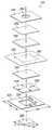
도 2 및 3을 참조하여, 감압 드레싱(104)은 조직 부위(108)에 위치되도록 구성된 계면층(220), 및 조직 부위((108)) 주위에 감압 드레싱(104)을 밀봉하는 밀봉층(222)을 포함한다. 제 1 매니폴드층(224)은 감압을 계면층(220) 및 조직 부위(108)로 분배시키기 위해 계면층(220)과 유체 연통된다(in fluid communication). 흡수층(228)은 제 1 매니폴드층(224), 계면층(220) 및 조직 부위(108) 중 적어도 하나로부터 액체를 흡수시키기 위해 제 1 매니폴드층(224)과 유체 연통하게 위치된다. 디버터층(232)은 흡수층(228)에 인접하여 위치된다. 제 2 매니폴드층(236)은 디버터층(232)과 유체 연통하게 위치되고, 기액 분리기(240)는 제 2 매니폴드층(236)에 인접하여 위치된다. 커버(244), 또는 드레이프는 기액 분리기(240)에 인접하여 위치한다.2 and 3, the pressure reducing dressing 104 includes an
감압 드레싱(104)의 계면층(220)은 조직 부위(108)를 접촉시키도록 구성된다. 계면층(220)은 감압 드레싱(104)에 의해 치료되는 조직 부위(108)와 부분적으로 또는 완전하게 접촉될 수 있다. 조직 부위(108)에 상처가 있을 시, 계면층(220)은 부분적으로 또는 완전하게 상처를 채운다.The
계면층(220)은 이행되는 치료 유형과 같은 다양한 요인들 또는 조직 부위(108)의 특성 및 크기에 따른 크기, 형상 또는 두께를 가질 수 있다. 예를 들면, 계면층(220)의 크기 및 형상은 조직 부위(108)의 특별한 부분을 덮기 위해 또는 조직 부위(108)를 채우기 위해 또는 부분적으로 채우기 위해 사용자에 의해 맞춰질 수 있다. 도 3에 도시된 계면층(220)이 정사각형을 가지지만, 계면층(220)은 원형, 타원형, 다각형, 불규칙한 형상 또는 임의의 다른 형상으로 형성될 수 있다.The
예시적인 일 실시예에서, 계면층(220)이 조직 부위(108)에 접촉되거나 상기 조직 부위 근처에 접촉될 시에, 계면층(220)은 감압을 조직 부위(108)에 제공하기 위해 매니폴드로서 기능하는 폼 물질(foam material)이다. 폼 물질은 소수성 또는 친수성일 수 있다. 제한되지 않은 일 예에서, 계면층(220)은 텍사스, 산 안토니오의 Kinetic Concepts, Inc.으로부터 판매되는 GranuFoam® 드레싱과 같은 개방-셀의 망상형 폴리우레탄 폼(open-cell, reticulated polyurethane foam)이다.In one exemplary embodiment, when the
계면층(220)이 친수성 물질로부터 구성된 예에서, 계면층(220)은 유체를 조직 부위(108)로부터 멀리 전달하는 기능도 하면서, 매니폴드로서 감압을 조직 부위(108)에 연속적으로 제공한다. 계면층(220)의 전달 속성은 모관류(capillary flow) 또는 다른 전달 매커니즘들에 의해 유체를 조직 부위(108)로부터 멀리 인출한다. 친수성 폼의 예는 폴리비닐 알코올, 텍사스, 산 안토니오의 Kinetic Concepts, Inc.으로부터 판매되는 V.A.C. WhiteFoam®와 같은 개방-셀 폼이다. 다른 친수성 폼들은 폴리에테르로부터 구성된 것들을 포함할 수 있다. 친수성 특성을 포함할 수 있는 다른 폼들은 친수성을 제공하기 위해 처리되거나 코팅된 소수성 폼들을 포함한다.In the example where the
계면층(220)은, 감압이 감압 드레싱(104)을 통하여 가해질 시에 조직 부위(108)에서 육아 형성(granulation)을 더 촉진시킬 수 있다. 예를 들면, 계면층(220)의 표면의 일부 또는 모두는 고르지 않고, 조잡하고, 또는 감압이 계면층(220)을 통해 가해질 시에 조직 부위(108)에서 마이크로스트레인 및 응력을 일으키는 재그형 프로파일(jagged profile)을 가질 수 있다. 이러한 마이크로스트레인 및 응력은 새로운 조직 성장을 촉진하는데에 제시되어 왔다.The
일 실시예에서, 계면층(220)은 감압 드레싱(104)의 사용 다음에 환자 몸체로부터 제거될 필요가 없는 생체분해성 물질들(bioresorbable materials)로부터 구성될 수 있다. 적합한 생체분해성 물질들은 PLA(polylactic acid) 및 PGA(polyglycolic acid)의 중합체 혼합물을 포함할 수 있지만, 이에 제한되지는 않는다. 중합체 혼합물은 폴리카보네이트(polycarbonates), 폴리푸마레이트(polyfumarates) 및 카프라락톤(capralactones)도 포함할 수 있지만, 이에 제한되지는 않는다. 계면층(220)은 나아가 새로운 세포 성장을 위한 스캐폴드(scaffold) 역할을 할 수 있거나, 또는 스캐폴드 물질은 세포 성장을 촉진시키기 위해 계면층(220)과 함께 사용될 수 있다. 스캐폴드는 셀 성장용 템플릿(template)을 제공하는 3-차원 다공성 구조물과 같은, 세포의 성장 또는 조직의 형성을 향상시키거나 촉진시키기 위해 사용된 기질 또는 구조물이다. 스캐폴드 물질들의 예시적인 예들은 인산칼슘(calcium phosphate), 콜라겐, PLA/PGA, 산호의 수산화인회석(coral hydroxy apatites), 탄산염 또는 가공된 동종 이식 물질을 포함한다.In one embodiment,
감압 드레싱(104)의 밀봉층(222)은 개구부 또는 개방부(231)를 포함하고, 조직 부위(108) 주위에 밀봉을 제공한다. 밀봉층(222)은 감압 드레싱(104)의 누출로부터 감압 드레싱(104)에 가해진 감압을 막기 위해 조직 부위(108)의 일부 주위에서 개스킷(gasket)으로 역할할 수 있다. 밀봉층(222)은 조직 부위(108)에서 계면층(220)을 확보하도록 사용될 수도 있다. 커버(244)의 주름을 이용하여, 커버(244)가 조직 부위(108)를 둘러싸는 조직에 적용되면, 밀봉층(222)은 커버(244)의 주름진 영역을 유지하는데 도움을 준다.The
밀봉층(222)은 조직 부위(108) 주위에서 밀봉을 제공할 수 있는 크기 및 두께일 수 있다. 도 2의 예에서, 밀봉층(222)의 길이(L2) 및 폭(W2) 각각은 계면층(220)의 길이(L1) 및 폭(W1)보다 크다. 이로써, 밀봉층(222)의 부분들은 계면층(220)의 에지들을 지나 연장된다. 이러한 부분들은 조직 부위(108)를 둘러싸는 조직과 직접 접촉되어, 조직 부위(108) 및 계면층(220) 주위에 밀봉을 제공한다.
도 3에 도시된 밀봉층(222)은 정사각형 형상을 가지는 한편, 밀봉층(222)은 조직 부위(108) 또는 계면층(220) 주위에 밀봉을 제공하는 다른 형상을 가질 수도 있다. 제한되지 않은 예의 다른 형상들은 원, 타원, 다각형 형상, 불규칙한 형상, 또는 조직 부위(108) 또는 계면층(220)을 둘러싸는 조직의 윤곽에 맞춰지는 형상을 포함한다.While the
밀봉층(222)은 조직 부위(108)의 치료 부분 주위를 밀봉할 수 있는 임의의 물질로 구성될 수 있다. 예시적인 일 실시예에서, 밀봉층(222)은 히드로겔(hydrogel)을 포함하거나 상기 히드로겔로 구성될 수 있다. 밀봉층(222)은 하이드로콜로이드(hydrocolloid) 또는 실리콘 중 하나 또는 둘 다를 포함할 수도 있다.
밀봉층(222)이 계면층(220)에 인접하여 배치된 것으로 도시되었지만, 밀봉층(222)은 감압 드레싱(104)의 층들에 인접하거나, 상기 층들 사이에서 위치될 수 있다. 밀봉층(222)의 위치에 관한 추가적인 상세한 설명은 도 2를 참조하여 다음에서 더 상세하게 논의된다.Although the
감압 드레싱(104)은, 계면층(220)으로 감압을 분배시키는 제 1 매니폴드층(224) 및 상기 계면층(220)으로부터의 삼출액과 같은 인출액(withdrawing liquid)도 포함한다. 밀봉층(222)이 계면층(220)에 인접하여 위치될 시에, 액체는 개구부(231)를 통해 조직 부위(108)로부터 인출될 수 있다. 감압이 감압 드레싱(104)에 가해지면, 상기 액체는 계면층(220)에 의해 조직 부위(108)로부터 전달되고, 제 1 매니폴드층(224)에 의해 밀봉층(222)의 개구부(231)를 통하여 인출된다.The reduced pressure dressing 104 also includes a
일 실시예에서, 개구부(231)의 길이(L3) 및 폭(W3)은 계면층(220)의 길이(L1) 및 폭(W1)보다 작다. 그러나, 다른 실시예들에서, 특히, 하나 이상의 다른 층들이 밀봉층(222)과 계면층(220) 사이에서 배치되는 이러한 실시예에서, 개구부(231)의 길이(L3) 및 폭(W3)은 계면층(220)의 길이(L1) 및 폭(W1)보다 같거나 클 수 있다. 도 3에 도시된 개구부(231)가 정사각형 형상을 가지는 한편, 이 대신 개구부(231)는 밀봉층(222)이 밀봉을 제공하도록 하는 다른 임의의 형상을 가지면서, 조직 부위(108)로부터 액체의 통과를 용이하게 할 수 있다.In one embodiment, the length L3 and the width W3 of the
제 1 매니폴드층(224)은 임의의 크기, 형상 또는 두께를 가질 수 있다. 예를 들면, 제 1 매니폴드층(224)의 크기 및 형상은 흡수층(228)의 이용의 상이한 레벨을 제공하도록 맞춰질 수 있다. 제 1 매니폴드층(224)의 크기 및 형상은 감압 드레싱(104)의 다른 구성요소들의 크기 및 형상, 예를 들면 감압 드레싱(104)의 계면층(220), 밀봉층(222), 개구부(231), 흡수층(228) 또는 다른 층들의 크기 및 형상에 기초하여 맞춰질 수도 있다.The
제 1 매니폴드층(224)은 감압을 조직 부위(108)에 분배시킬 수 있는 생체 적합성 다공성 물질이다. 제 1 매니폴드층(224)은 폼, 가제, 펠트형 매트(felted mat) 또는 특별한 생물 적용에 적합한 다른 물질로 구성될 수 있다. 제 1 매니폴드층(224)은 감압의 분배를 용이하게 하도록, 또는 조직 부위(108)로의 유체 또는 상기 조직 부위로부터의 유체를 용이하게 하도록 복수의 유동 채널들 또는 통로들을 포함한다. 일 실시예에서, 제 1 매니폴드층(224)은 다공성 폼(porous foam)이고, 유동 채널들로서 작용하는, 복수의 상호연결된 셀들 또는 구멍들을 포함한다. 다공성 폼은 GranuFoam® 드레싱과 같은 개방-셀의 망상형 폴리우레탄 폼일 수 있다. 개방-셀 폼이 사용되는 경우, 다공성은 약 400 내지 600 미크론일 수 있거나, 또는 감압을 적절하게 매니폴드할 수 있는 임의의 다른 다공성일 수 있다. 유동 채널들은 개방 셀들을 가진 제 1 매니폴드층(224)의 부분 모두에 유체 연통을 가능케 한다. 형상 및 크기에서 셀들 및 유동 채널들은 균일할 수 있거나, 또는 형상 및 크기에서 패턴화되거나 임의의 변형들을 포함할 수 있다. 제 1 매니폴드층(224)의 셀들의 형상 및 크기의 변형들로 인해, 유동 채널들은 변형되고, 상기와 같은 특성은 제 1 매니폴드층(224)을 통하여 유체의 유동 특성을 변화시키기 위해 사용될 수 있다. 제 1 매니폴드층(224)은 소수성 또는 친수성일 수 있다. 일 실시예에서, 제 1 매니폴드층(224)은 계면층(220)으로서 동일한 물질로 구성될 수 있다.The
일 실시예에서, 제 1 매니폴드층(224)은 조직 부위(108)로부터 삼출액과 같은 액체와의 접촉에 따라 연장되는 물질로 구성될 수 있고, 그 결과, 제 1 매니폴드층(224)은 상처 부위를 채울 수 있고, 그렇지 않으면 조직 부위(108)와 접촉된다. 이 실시예에서, 제 1 매니폴드층(224)은 계면층(220)이 제거될 수 있게 할 수 있고, 이로 인해 구성은 간단해지고, 감압 드레싱(104)의 두께 또는 측면은 감소된다.In one embodiment, the
감압 드레싱(104)의 흡수층(228)은 제 1 매니폴드층(224)에 의해 분배된 액체를 수용하고 흡수하는 제 1 매니폴드층(224)에 인접하여 배치된다. 제 1 매니폴드층(224)은 다수 방향 화살표(239)로 일반적으로 제시된 바와 같이, 제 1 매니폴드층(224)의 에지를 향하여 방사형 외부 방향으로, 조직 부위(108)로부터 액체의 이동을 용이하게 하고, 그 결과, 액체는 흡수층(228)에 대해 더 균일하게 분배된다. 액체가 흡수층(228)의 표면에 대해 더 균일하게 분배되는 경우, 흡수층(228)은 액체를 더 유지할 것이다.The
본원에서 사용된 바와 같이, 층의 "표면적"은 층의 영역 크기로 언급되고, 이는 다른 층들에 인접하거나 접촉하여 위치된 평면에서 결정될 수 있다. 도 3에서 도시된 예에서, 제 1 매니폴드층(224) 및 흡수층(228)의 표면적들은 각각의 층들의 길이 및 폭을 곱하여 결정될 수 있고, 이때 상기 길이 및 폭은 개구부(231)의 길이(L3) 및 폭(W3)을 포함하는 평면에 실질적으로 평행한 평면에서 계측된다.As used herein, the "surface area" of a layer is referred to as the area size of the layer, which can be determined in the plane located adjacent or in contact with the other layers. In the example shown in FIG. 3, the surface areas of the
도 3의 개구부(231)의 표면적(L3 x W3으로 정의)은 제 1 매니폴드층(224)의 표면적 및 흡수층(228)의 표면적보다 작을 수 있다. 제 1 매니폴드층(224)이 제 1 매니폴드층(224)의 에지를 향하여 방사형으로 액체를 분배시키는데 실패를 하면, 흡수층(228)은 개구부(231)와 동일한 크기를 가진 흡수층(228)의 일부에서 액체를 우선 흡수한다. 그러나, 제 1 매니폴드층(224)이 다수 방향 화살표(239)로 나타난 방향으로 조직 부위(108)로부터 액체를 방사형으로 분배시킬 수 있기 때문에, 흡수층(228)의 보다 큰 표면적은 액체에 노출되고, 흡수층(228)은 유체의 큰 볼륨을 저장할 수 있다. 감압 드레싱(104)이 우선 감압과 함께 사용하기 위해 설계되는 한편, 다수 방향 화살표(239)에 의해 나타난 방향으로 조직 부위(108)로부터의 액체 분배는 감압의 적용 또는 감압의 부재 동안에 일어날 수 있다. 흡수층(228)의 더 완전한 이용은, 감압이 감압 드레싱(104)에 적용되지 않을 시에도, 제 1 매니폴드층(224)을 사용하여 달성될 수 있다.The surface area (defined as L3 x W3) of the
흡수층(228)은 밀봉층(222)의 개구부(231)를 통해 계면층(220) 및 제 1 매니폴드층(224)을 통하여 조직 부위(108)로부터 삼출액과 같은 액체를 흡수하도록 구성된다. 흡수층(228)은 매니폴드로 구성될 수도 있고, 이러한 층들을 통하여 감압을 조직 부위(108)에 전달한다. 흡수층(228)은 조직 부위(108)로부터 삼출액과 같은 액체를 흡수할 수 있는 임의의 물질로 구성될 수 있다. 일 실시예에서, 흡수층(228)은 고흡수성 섬유(super absorbent fiber)로 구성될 수 있다. 고흡수성 섬유들은 상기 섬유에 대해 물리적 또는 화학적 변화와 함께 액체 상에서 유지되거나 상기 액체와 연결될 수 있다. 제한적이지 않은 일 예에서, 고흡수성 섬유는 Technical Absorbents®로부터의 고흡수성 섬유(SAF) 물질을 포함할 수 있다. 흡수층(228)은, 섬유들이 조직 부위(108)로부터 액체를 흡수하는 섬유질 물질의 시트(sheet) 또는 매트(mat)일 수 있다. 섬유들을 포함하는 흡수층(228)의 구조는 엮어지거나 엮어지지 않을 수 있다. 흡수층(228)의 섬유들은 액체와의 접촉에 따라서 겔일 수 있고, 이로 인해 액체는 가둬지게 된다. 섬유들 사이의 공간들 또는 빈 곳은 감압 드레싱(104)에 가해진 감압이 흡수층(228) 내에서, 그리고 상기 흡수층을 통하여 전달되도록 할 수 있다. 일 실시예에서, 흡수층(228)의 섬유들의 섬유 밀도는 밀리미터당 약 1.4 그램일 수 있다.
흡수층(228)은 임의의 크기, 형상, 또는 두께를 가질 수 있다. 추가적인 액체 저장 능력이 감압 드레싱(104)에 대해 바람직한 경우, 보다 크거나 두께가 더 큰 흡수층(228)이 사용될 수 있다. 또 다른 예에서, 흡수층(228)의 크기 및 두께는 공간 절약, 편의, 소형화 또는 비용 면에서 감소될 수 있다.
감압 드레싱(104)은 흡수층(228)에 인접하여 배치된 디버터층(232), 상기 디버터층(232)에 인접하여 배치된 제 2 매니폴드층(236), 및 제 2 매니폴드층(236)에 인접하여 배치된 기액 분리기(240)를 포함할 수도 있다. 디버터층(232)은 복수의 홀들(247)을 포함하고, 상기 복수의 홀들(247)을 통하여 감압원(110)(도 1 참조)으로부터의 감압은 가해진다. 감압은 제 2 매니폴드층(236)에 의해 디버터층(232)으로 분배된다. 홀들(247)은 흡수층(228)의 성능을 향상시키기 위해 흡수층(228)의 부분들에 감압을 적용하는 패턴에 배치될 수 있어서, 조직 부위(108)로부터 유체를 더 흡수시킴에 따라, 감압을 조직 부위(108)에 전달한다. 도 3에 도시된 실시예에서, 복수의 홀들(247)은, 디버터층(232)의 중심으로부터 멀리 떨어져 디버터층(232)의 주변부 주위의 패턴에 위치되고, 그 결과, 감압은 흡수층(228)의 중심 영역으로부터 멀리 떨어진 흡수층(228)에 가해진다. 디버터층(232)은, 흡수층(228)의 흡수 성능 및 흡수 효율이 디버터층과 함께 사용되지 않은 흡수층에 대해 증가되는 것을 확보하기 위해서, 제 1 매니폴드층(224)과 함께 작용한다. 흡수층(228) 전체에 액체의 분배가 더 잘되게 제공됨으로써, 디버터층(232)은 또한, 흡수층(228)이 드레싱(104)에 감압을 매니폴드할 수 있는 시간량을 증가시킨다.The pressure reducing dressing 104 may include a
디버터층(232)은 인접한 흡수층의 감압 전달 및 저장 성능을 향상시키는 임의의 물질로 구성될 수 있다. 예를 들면, 디버터층(247)은 액체나 가스에 실질적으로 불침투성인 물질로 구성될 수 있다. 대안적으로, 대신에 디버터층(232)이 구성된 물질은 가스 침투율과 일치하는 소정의 수분 증기 전달율을 가질 수 있다. 어느 예이든, 디버터층(232)은, 디버터층(232)이 구성된 가스-침투성 물질에 의해 허용된 홀들의 패턴들보다 큰 액체 또는 가스의 볼륨을 전달하는 홀들의 패턴을 여전히 포함할 수 있다. 그러나, 액체가 아닌 가스로의 디버터층(232)의 침투율로 인해, 드레싱을 통한 감압의 전달은 증가되면서, 디버터층(232)의 주변 주위 또는 주변 근처에서 액체는 여전히 흐르게 된다는 것을 주목해야 한다.The
도 3에 도시된 실시예에서, 감압은 홀들(247)을 통하여 액체 유동을 생성한다. 홀들(247)을 통한 유체 유동은 흡수층(228)의 중심 영역으로부터 멀리 떨어져 흡수층(228) 내로 액체를 잡아당긴다. 홀들(247)의 존재 및 상기 홀들(247)을 통한 유체 유동은 흡수층(228)의 중심 영역에서 액체의 흡수율을 낮출 수도 있고, 흡수층(228)이 보다 큰 영역 상의 액체를 흡수시키도록 할 수도 있다. 이로써, 가스 및 액체는 디버터층(232)보다 조직 부위(108)에 더 인접하게 배치될 수 있는 다른 층들 또는 흡수층(228)의 중심을 통하여 이동하는 것에 단지 제한되지 않는다. 가스 및 액체 모두가 흡수층(228)의 에지들을 향하여 방사형 외부로 향해지기 때문에, 흡수성 물질의 보다 큰 부분은 조직 부위(108)로부터 액체에 노출되고, 그러므로, 흡수층(228)의 보다 큰 부분은 액체의 보다 큰 볼륨을 저장하거나 가두기 위해 사용될 수 있다.In the embodiment shown in FIG. 3, the reduced pressure produces a liquid flow through the
흡수층(228)의 보다 큰 용도로 인해, 감압 드레싱(104)을 배치할 필요없이 감압 드레싱(104)은 더 긴 시간 동안 사용된다. 흡수층(228)의 에지들을 향한 가스 및 액체의 분배 필요는, 액체가 감압 드레싱(104)을 통하여 조직 부위(108)로부터 멀리 떨어져서 흐를 수 있는 속도로 인해 감압의 존재에서 더 클 수도 있다.Due to the larger use of the
디버터층(232)은 우선, 감압 또는 유체 유동을 흡수층(228)의 주변 영역으로 전환하는데 도움을 주는 바와 같이 기술되어 왔다. 대안적으로, 대신에 디버터층(232)은 특별한 영역, 즉, 흡수층(228)의 대상 영역으로 감압을 전환하는데 도움을 주기 위해 구성될 수 있어, 대상 영역 내의 액체 흡수를 촉진시킨다. 예를 들면, 조직 부위 및 드레싱이 특별한 흡수층의 주변 영역에서 액체 수집을 자연스레 초래하도록 구성되었다면, 디버터층은 흡수층의 중심 영역 내에서 액체 수집을 촉진시키기 위해 구성될 수 있다. 이 특별한 예에서, 중심 영역은 대상 영역일 수 있다.The
도 2 및 3을 참조하여, 제 2 매니폴드층(236)은 디버터층(232)의 표면에 대해 더 감압이 균일해지도록 분배한다. 제 2 매니폴드층(236)은 유체를 분배 또는 매니폴드할 수 있는 임의의 물질로 구성될 수 있다. 일 예에서, 제 2 매니폴드층(236)은 제 1 매니폴드층(224)와 동일하거나 유사한 물질로 구성될 수 있다. 이 예에서, 제 2 매니폴드층(236)은 다공성 폼을 형성하는, 복수의 상호연결된 셀들을 포함할 수 있다. 제 2 매니폴드층(236)은 흡수층(228)에 의해 흡수되지 않은 조직 부위(108)로부터 삼출액과 같은 액체를 수집할 수도 있다. 제 2 매니폴드층(236)은 임의의 크기, 형상 또는 두께를 가질 수 있다.Referring to FIGS. 2 and 3, the
감압 드레싱(104)의 일 실시예에서, 기액 분리기(240)는 기액 분리기(240)를 통한 액체의 통과를 억제하거나 막는 소수성 필터일 수 있다. 대안적으로, 기액 분리기(240)는 중력에 기반한 배리어 시스템(gravity-based barrier system)일 수 있거나, 또는 유체 스트림이 표면 상에 거쳐갈 시에 유체 스트림으로부터의 액체 압축 또는 액체 분리를 촉진시키는 친수성 표면을 포함하는 장치일 수 있다. 기액 분리기들(240)의 다른 예들은 소결 금속들(sintered metals), 소결 나일론들 또는 다른 임의의 물질 또는 액체를 유체 스트림으로부터 분리할 수 있는 장치, 그렇지 않으면 액체의 통과를 억제하거나 막으면서 가스의 통과를 가능케 할 수 있는 장치를 포함할 수 있다.In one embodiment of the reduced pressure dressing 104, the gas-
액체의 유동을 제지시키거나 막음으로써, 기액 분리기(240)는 액체가 관형 어댑터(116) 또는 도관(112)(도 1 참조)에 이르지 못하게 한다. 액체를 도관(112)에 이르지 못하게 함으로써, 기액 분리기(240)는 또한 액체가 감압원(110)에 이르지 못하도록 한다.By restraining or blocking the flow of liquid, gas-
기액 분리기(240)가 조직 부위(108)로부터의 액체로 흠뻑 젖고(saturated), 막히고, 차단되고, 그리고/또는 축축해질 시에, 기액 분리기(240)는 조직 부위(108)로의 감압의 통과를 막을 수 있다. 기액 분리기(240)에 인접한 층이 액체로 흠뻑 젖을 시에 기액 분리기(240)는 조직 부위(108)로의 감압의 통과도 막을 수 있다. 예를 들면, 특별한 실시예에서, 흡수층(228)이 기액 분리기(240)에 인접한 경우, 액체로 흡수층(228)을 흠뻑 적시는 것은 기액 분리기(240)가 감압의 통과를 막도록 할 수 있다. 기액 분리기(240)와 흡수층(228) 사이의 디버터층(232)의 존재는 기액 분리기(240)가 감압의 통과를 차단하기 전의 시간 구간을 연장시킨다.When gas-
기액 분리기(240)는 임의의 크기, 형상 또는 두께를 가질 수 있다. 일 예에서, 기액 분리기(240)는 비용을 고려하면, 감압 드레싱(104)의 다른 층들보다 더 낮을 수 있다. 기액 분리기(240)는 커버(244)에서 관형 어댑터(116) 및 개구부(260) 보다 폭이 더 클 수도 있고, 그 결과, 조직 부위(108)로부터의 액체는 관형 어댑터(116) 또는 개구부(260)에 이를 수 없다.Gas-
감압 드레싱(104)의 커버(244)는 감압 드레싱(104)의 적어도 일부를 덮는다. 일 실시예에서, 커버(244)는 감압 드레싱(104)의 다수 층들을 완전하게 덮을 수 있다. 이 실시예에서, 커버(244)는 조직 부위(108)로 감압 드레싱(104)을 안전하게 하는데, 그리고 조직 부위(108) 주위에 밀봉을 유지하는데 확실히 할 수 있거나 또는 도움을 줄 수 있다. 이에 대해, 커버(244) 및 밀봉층(222) 모두는 조직 부위(108) 주위의 밀봉을 생성하기 위해 함께 작용할 수 있다. 커버(244)는 감압 드레싱(104) 및 조직 부위(108)에 대해 보호 배리어도 제공할 수 있다.Cover 244 of the reduced pressure dressing 104 covers at least a portion of the reduced pressure dressing 104. In one embodiment, cover 244 may completely cover multiple layers of pressure
도 2 및 3에 도시된 실시예에서, 커버(244)는 커버(244)와 디버터층(232) 사이의 구성요소들 및 층들을 덮고 안전하게 할 수 있다. 이 실시예에서, 커버(244)는 디버터층(232)에 접착 또는 다른 방식으로 안전해질 수 있다. 그 후, 커버(244)와 유사한 물질로 구성된 디버터층(232)은 조직 부위(108)에 있거나 또는 그 근처에 있는 조직 및 밀봉층(222) 중 하나 또는 둘 다에 대해 안전하게 된다. 이 실시예의 디버터층(232)은 조직 부위(108)에서 디버터층(232) 아래의 구성요소들 및 층들을 안전하게 하고 밀봉시킨다.In the embodiment shown in FIGS. 2 and 3, the
일 실시예에서, 커버(244)는 접착 드레이프일 수 있다. 커버(244)의 접착은, 커버(244)가 만들어진 물질의 특성으로 인한 것일 수 있거나, 또는 커버(244)의 표면 상에 배치된 접착층으로 인한 것일 수 있다. 커버(244)의 임의의 부분은 접착제를 포함할 수 있다. 예를 들면, 커버(244)의 전체 조직 대향 측은 접착제를 포함할 수 있다. 접착제가 제공될 시에, 커버(244)는 관형 어댑터(116)의 적어도 일부, 조직 부위(108)를 둘러싸는 조직에 접착될 수 있거나, 또는 감압 드레싱(104)의 임의 층 또는 구성요소에 접착될 수 있다. 또 다른 실시예에서, 커버(244)의 조직 대향 측의 주변부들만 접착제를 포함할 수 있다. 이 특별한 경우에서, 접착제로 덮인 주변부들은 디버터층(232), 밀봉층(222), 및 조직 부위(108)를 둘러싸는 조직에 접착되도록 구성될 수 있다.In one embodiment, cover 244 may be an adhesive drape. The adhesion of
또 다른 실시예에서, 커버(244)가 축축한 표면들에 접착되는 것이 아니고 건조된 표면들에 접착되도록 설계될 수 있다. 이로써, 커버(244)를 적용할 시에, 커버(244)는 축축한 장갑 또는 손에 들려지지 않고, 이로 인해, 커버(244)가 건조된 상처주위 영역과 같은 건조된 조직 부위 상에 놓일 때까지 커버(244)를 보다 손쉽게 다루는 것은 가능해진다. 커버(244)는 임의의 크기, 형상 또는 두께를 가질 수 있다. 일 예에서, 커버(244)는 감압 드레싱(104)의 임의의 층 또는 구성요소들 보다 클 수 있다. 또 다른 예에서, 밀봉층(222)의 크기는 커버(244)의 크기보다 클 수 있다.In yet another embodiment, the
감압은 커버(244)의 개구부(260)를 통해 감압 드레싱(104)의 복수의 층들에 적용될 수 있다. 도 2 및 3의 예에서, 개구부(260)가 커버(244) 상의 중심에 위치된 것을 알 수 있다. 그러나, 개구부(260)는 커버(244)의 에지에 인접한 커버(244)의 주변부를 포함하여, 커버(244) 어디에든 위치될 수 있다. 개구부(260)가 원형으로 도시되어 있지만, 개구부(260)는 임의의 형상을 가질 수 있다. 일 예에서, 개구부의 형상은 관형 어댑터(116)의 하나 이상의 부분들에 윤곽을 나타내도록 구성된다.Decompression may be applied to the plurality of layers of the decompression dressing 104 through the
관형 어댑터(116)는 도관(112)과 감압 드레싱(104) 사이의 계면을 제공한다. 특히, 관형 어댑터(116)는 도관(112)과 함께 유동적으로 연통되고, 그 결과, 도관(112)은 감압을 관형 어댑터(116)를 통하여 감압 드레싱(104) 및 조직 부위(108)에 전달한다.
도 1 및 2를 참조하여, 관형 어댑터(116)는 개구부(260)에 인접하여 구성된 종래의 커넥터 패드일 수 있거나, 또는 상기 개구부 내에 부분적으로 배치될 수 있다. 대안적으로, 관형 어댑터(116)는 낮은 측면 돔 형상을 가질 수 있거나, 또는 관형 어댑터(116)는 다른 형상일 수 있다. 관형 어댑터(116)의 낮은 측면은 감압 드레싱(104)이 사용자에 의해 사용되기에 작고 편리하도록 도움을 준다. 관형 어댑터(116)는 플렌지(266)를 포함하고, 상기 플렌지는 관형 어댑터(116)의 주변부 주위에 배치된다. 도 2 및 3에 도시된 실시예에서, 개구부(260) 근처의 커버(244)의 조직 대향 측은 플렌지(266)에 접착되도록 구성될 수 있고, 그 결과, 관형 어댑터(116)는 감압 드레싱(104)의 적어도 하나의 층 또는 구성요소에서 확보된다.1 and 2,
도 2 및 3에 도시되지 않았지만, 일 실시예에서, 감압 드레싱(104)은 냄새 필터를 포함한다. 냄새 필터는 냄새를 유지하거나 또는 냄새가 감압 드레싱(104)에서 나가지 못하도록 한다. 냄새 필터는 숯을 포함할 수 있는 탄소 냄새 필터일 수 있다. 일 예에서, 냄새 필터는 숯 의류이다. 냄새 필터는, 예를 들면, 커버(244)와 기액 분리기(240) 사이에서 감압 드레싱(104) 어디에든 위치될 수 있다.Although not shown in FIGS. 2 and 3, in one embodiment, the pressure reducing dressing 104 includes an odor filter. The odor filter maintains odors or prevents odors from leaving the reduced pressure dressing 104. The odor filter may be a carbon odor filter that may include charcoal. In one example, the odor filter is charcoal garment. The odor filter may be located anywhere in the pressure reducing dressing 104, for example, between the
감압 드레싱(104)이 완전한 액체 저장 능력에 이르고 조직 부위(108)로부터 제거될 필요가 있을 시에, 감압 드레싱(104)은 사용자에게 주의를 주는 표시기(미도시)를 더 포함할 수 있다. 일 실시예에서, 표시기는 수분 존대의 다른 특성 또는 외형 형태를 변화시키리 수 있는 화학적 재질 또는 다른 재질 수 있다. 예를 들면, 표시기는 커버(244)와 흡수층(228) 사이의 층들 중 하나에 위치될 수 있고, 그 결과, 액체가 흡수층에 완전히 흠뻑 젖어들고, 표시기에 접촉된 흡수층을 통하여 인출될 시에, 표시기는 육안으로 색깔이 변한다. 일 실시예에서, 표시기는 기액 분리기(240)의 일부일 수 있다. 대신에 표시기는 개별 표시기 층의 일부일 수 있고, 이때, 상기 개별 표시기 층은 특별한 영역에서 수분의 존재를 신호로 전송하도록 드레싱 어디에든 위치될 수 있다. 표시기는 표시기가 배치된 위치를 사용자가 보도록 하기 위해 투명한 드레싱의 또 다른 층과 연동될 수 있다.When the pressure reducing dressing 104 reaches its full liquid storage capacity and needs to be removed from the
커버(244), 기액 분리기(240), 매니폴드들(224 및 236), 디버터층(232), 흡수층(228), 밀봉층(222) 및 계면층(220)이 도 3에서 실질적으로 정사각형 형상을 가졌지만, 이러한 구성요소들 각각, 이뿐 아니라, 다른 실시예들에 대해 본원에 개시된 다른 층들은 조직 부위(108)에 감압 치료를 적절하게 제공하기에 필요한 형상을 가질 수 있다. 예를 들면, 이러한 구성요소들 및 층들은 다각형, 사각형, 원형, 타원형, 불규칙한 형상, 맞춤 형상 또는 임의의 다른 형상일 수 있다.
감압 드레싱(104)의 다양한 층들이 다른 층들과 "인접한"것으로서 기술되는 한편, 용어 "인접한"은 층들이 바로 인접한 것을 일컫고, 또는 대안적으로, 층들이 그 사이의 개재된 다른 층들과 함께 위치된 것을 일컫는다. 용어 "층"은 드레싱의 다른 부분들 또는 영역들(즉 다른 층들)과는 다른 물질 속성 또는 기능을 가지는 드레싱의 부분들 또는 영역들을 일컫는다. 그러나, 용어 "층"은 공간적으로 제한하는 것을 의미하지는 않는다. 특별한 층과 연관된 속성 및 기능은 또 다른 기능의 속성 및 기능과 결합될 수 있고, 그 결과 복합적이고 상이한 속성 및 기능을 가진 단일 층은 생성된다. 특히, 예를 들면, 2 개 이상의 층들은 본래 구성요소들의 본래 물질 속성 또는 기능에 영향을 미치지 않고 단일 층을 생성하기 위해 물리적으로 또는 화학적으로 연결되거나 결합될 수 있다. 반대로, 본원에 기술된 드레싱의 특별한 층은 유사한 속성 또는 기능들을 각각 가진 2 개 이상의 층들로 분할될 수 있다.While the various layers of the pressure-
도 2를 특별하게 참조하여, 감압 드레싱(104)의 다수의 층의 특정 배치는 더 상세하게 기술된다. 계면층(220)의 조직 대향 측(316)은 조직 부위(108)에 인접하게 도시된다. 일 예에서, 계면층(220)의 조직 대향 측(316)은, 감압이 계면층(220)을 통해 적용될 시에, 조직 부위(108)의 육아 형성을 촉진하는, 고르지 못한 평면을 가진다. 고르지 못한 표면은 조직 부위(108) 상에서 미소응력(microstresses) 및 스트레인(strain)을 일으키는 섬유질 표면을 포함한다.With particular reference to FIG. 2, the specific arrangement of the multiple layers of the pressure reducing dressing 104 is described in more detail. The
밀봉층(222)은 흡수층(228)과 계면층(220) 사이를 포함하여, 커버(244)와 계면층(220) 사이 어디에든 배치될 수 있다. 도 2의 예에서, 밀봉층(222)은 제 1 매니폴드층(224)과 계면층(220) 사이에서 배치되고, 그 결과, 밀봉층(222)의 조직 대향 측(tissue facing side)(327)의 부분은 계면층(220)에 인접한다. 특히, 개구부(231)를 형성하는 밀봉층(222)의 내부 에지의 조직 대향 측은 계면층(220)에 인접한다.The
밀봉층(222)은 또한 돌출부들(overhangings portions)(329)을 포함하고, 상기 돌출부는 계면층(220)의 에지를 지나 연장된다. 돌출부들(329)은 조직 부위(108)에 접착되거나, 그렇지 않으면 접촉되기 위해 구성되고, 그 결과, 밀봉은 조직 부위(108)의 일부에서 생성된다. 예를 들면, 돌출부(329)는 상처 부위를 둘러싸는 상처주위에 접착되거나, 그렇지 않으면 상기 상처주위에 접촉되고, 그 결과 밀봉은 상처 부위에서 일어난다.The
제 1 매니폴드층(224)은 감압 드레싱(104) 어디에든 배치될 수도 있다. 일 예에서, 제 1 매니폴드층(224)은 계면층(220)과 흡수층(228) 사이에서 배치된다. 도 3의 제한적이지 않은 예에서, 제 1 매니폴드층(224)은 밀봉층(222)과 흡수층(228) 사이에 배치된다. 특히, 제 1 매니폴드층(224)의 조직 대향 측(336)의 일부는 밀봉층(222)의 개구부(231)에 인접한다. 이 예에서, 제 1 매니폴드층(224)의 드레이프 대향 측(337)은 흡수층(228)에 인접한다.The
도 2에 도시된 실시예에서, 흡수층(228)이 디버터층(232)과 제 1 매니폴드층(224) 사이에서 배치되는 것을 알 수 있다. 흡수층(228)의 조직 대향 측(342)은 제 1 매니폴드층(224)에 인접한다. 흡수층(228)의 드레이프 대향 측(343)은 디버터층(232)에 인접한다. 일 예에서, 디버터층(232)은 흡수층(228)과 커버(244) 사이에서 배치될 수 있다. 디버터층(232)의 조직 대향 측(347)은 흡수층(228)에 인접한다. 디버터층(232)의 드레이프 대향 측(348)은 제 2 매니폴드층(236)에 인접한다.In the embodiment shown in FIG. 2, it can be seen that the
제 2 매니폴드층(236)은 흡수층(228)과 커버(244) 사이에서, 또는 디버터층(232)과 커버(244) 사이에서 배치될 수 있다. 도 2에서, 제 2 매니폴드층(236)은 기액 분리기(240)와 디버터층(232) 사이에서 배치된다. 제 2 매니폴드층(236)의 조직 대향 측(352)은 디버터층(232)에 인접한다. 제 2 매니폴드층(236)의 드레이프 대향 측(353)은 기액 분리기(240)에 인접한다.The
기액 분리기(240)는 흡수층(228)과 커버(244) 사이에서, 또는 제 2 매니폴드층(236)과 커버(244) 사이에서 배치될 수 있다. 도 2에서, 기액 분리기(240)의 조직 대향 측(356)은 제 2 매니폴드층(236)에 인접한다. 기액 분리기(240)의 드레이프 대향 측(357)의 일부는 관형 어댑터(116)에 인접한다.Gas-
관형 어댑터(116)의 조직 대향 측(351)은 기액 분리기(240)에 인접한다. 또한, 관형 어댑터(116)의 일부가 커버(244)의 개구부로부터 돌출되는 것을 알 수 있다. 관형 어댑터(116)의 플렌지(flange)(266)는 커버(244)와 기액 분리기(240) 사이에서 개재되고, 그 결과, 커버(244)는 기액 분리기(240)와 같은 복수의 층들 중 넉어도 하나에 관형 어댑터(116)를 확보한다. 도 2에 도시된 바와 같이, 기액 분리기(240)는 커버(244)의 개구부(260) 보다 폭이 더 클 수 있고, 제 2 매니폴드층(236)은 기액 분리기(240)보다 폭이 더 클 수 있다.
커버(244)는 감압 드레싱(104) 모두 또는 일부를 덮을 수 있다. 예를 들면, 커버(244)의 말단들은 밀봉층(222)의 돌출부들(329) 상의 위치에서 종결된다. 파선(380)으로 나타난 바와 같이, 커버(244)는 조직 부위(108) 상의 위치에서도 종결될 수 있다.The
도 4를 참조하여, 디버터층(232)은 감압이 흡수층(228)의 부분들을 가하는 홀들 또는 다른 개구부들의 패턴을 포함한다(미도시). 홀들은 서로 다른 직경을 가진다. 특히, 홀들(450)의 직경은 홀들(247)의 직경보다 크다. 동작에서, 디버터층(232)은 흡수층(228)의 전달 성능을 더 향상시키기 위해 정사각형 흡수층(228)의 모서리들에 더 감압을 전달하는데, 이는 액체가 흡수층(228)의 중심으로부터 방사형 외부로 확산될 시에 상기 모서리들이 액체로 가득한 흡수층(228)의 마지막 부분이기 때문이다.Referring to FIG. 4, the
도 5 및 6을 참조하여, 예시적인 실시예에 따른 디버터층(545)은 액체와 접촉하여 연장된 임의의 물질로 구성될 수 있다. 예를 들면, 디버터층(545)은 히드로겔로 구성될 수 있다. 디버터층(545)은 하이드로콜로이드, 실리콘, 또는 실리콘 물질도 포함할 수 있다. 디버터층(545)은 홀들(547), 또는 다른 개구부들을 포함한다. 각 홀들(547)로부터 연장된 화살표 각각의 길이는 홀들을 통해 허용된 유동 또는 감압의 상대적인 양을 나타낸다. 도 5에서, 유동 또는 감압의 동일 양은 각각의 홀들(547)을 통해 전달된다.5 and 6, the
일부 감압 적용에서, 조직은 드레싱의 중심으로부터 멀리 떨어진 영역에서 삼출액을 더 생성할 수 있다. 이러한 경우에서, 많은 양의 액체는 홀들(547)의 일부를 통과할 수 있고, 이때 상기 홀들은 삼출액의 주요 지점 상에 위치된다. 도 6의 예에서, 삼출액의 주요 지점은 홀들(648) 근처에서 일어난다. 이로써, 홀들(648)은 조직 부위로부터의 액체와의 접촉으로 인해 더 작고, 팽창되고, 실질적으로 폐쇄되는 것을 알 수 있다. 홀들(648)의 제한으로 인해, 잔류한 홀들(547)을 통하여 우선적으로 흐르게 되어, 이로 인해, 드레싱의 인접한 흡수층에 대한 유동이 동일하게 된다. 특히, 도 6에 도시된 바와 같이, 디버터층(545)의 홀들(547)은 홀들(648) 보다 감압의 양을 더 크게 전달한다. 상기와 같은 방식으로 유동 및 감압을 동일하게 함으로써, 도 2 및 3의 흡수층(228)과 같은 흡수층은 조직 부위에서의 삼출액의 주요 지점의 위치, 또는 액체가 흡수층에 의해 흡수되는 패턴의 위치에 상관없이 완전하게 더 이용될 수 있다.In some reduced pressure applications, the tissue may further produce exudates in areas remote from the center of the dressing. In such a case, a large amount of liquid may pass through some of the
도 7 및 8을 참조하여, 예시적인 실시예에 따른 디버터층(745)은, 디버터층(745)의 표면으로부터 돌출되고, 복수의 채널들(787) 그 사이를 형성하거나 정의하기 위해 디버터층(745)의 중심으로부터 주변까지 방사형 외부로 연장되는 복수의 리지들(ridges)(785)을 포함한다. 리지들(785)은 만곡되어 디버터층(745)의 중심부로 모일 수 있다. 디버터(745)의 리지면은 흡수층(미도시)에 인접하고, 그 결과, 채널들(787)은 디버터층(745)의 중심부와 주변부 사이에서 방사형으로 연장된 통로들(887 및 888)(도 8)을 형성하기 위해 폐쇄된다. 도 8에서, 각각의 통로들(887)이 방해받지 않는다는 것을 알 수 있고, 그러므로, 실질적으로 감압의 동일 양은 각각의 통로들을 통해 자유롭게 흐른다. 그러나, 일부 감압 적용에서, 조직 부위(108)(미도시)로부터의 액체는 채워지고, 통로들(888)을 차단한다. 예를 들면, 이는, 조직 부위로부터 조직 부위로부터 삼출액의 주요 지점이 디버터층(745)을 포함하여, 드레싱의 중심으로부터 멀리 떨어져서 위치될 시에 일어날 수 있다. 액체의 양이 통로들(887)보다 통로들(888)을 통하여 더 크게 흐르기 때문에, 통로들(888)은 액체로 채워지고, 음영부들(889)로 나타낸 바와 같이, 통로들(888)에 인접한 흡수층(228)의 흠뻑 젖은 부분들에 의해 차단된다. 이로써, 디버터층(745) 상의 화살표들에 의해 나타난 바와 같이, 차단된 통로들(888)보다는 통로들(887)을 통하여 감압의 더 큰 양의 가해진다. 그 후, 통로들(887)은, 디버터층(745)에 인접한 흡수층(228) 모두가 흠뻑 젖을 때까지 감압 및 유체 유동에 대한 바람직한 통로가 된다. 상기와 같은 방식으로 유동이 동일하게 됨으로써, 흡수층(228)은 조직 부위 상의 삼출액의 주요 지점의 위치, 또는 액체가 흡수층(228)에 의해 흡수되는 패턴의 위치에 상관없이 더 완전하게 이용된다.With reference to FIGS. 7 and 8, the
도 9를 참조하여, 디버터층(945)은 예시적인 실시예에 따라서 도시된다. 디버터층(945)은 디버터층(945) 주위에 홀들(947) 또는 다른 개구부들의 패턴을 포함한다. 그러나, 도 2 및 3의 디버터층(232)과 달리, 디버터층(945)은 홀들(947)을 포함하지 않는 부분(931)을 포함한다. 부분(931)은 중심을 벗어나(off-center) 위치된 관형 어댑터(관형 어댑터(116)와 유사함)와 정렬될 수 있다. 감압이 관형 어댑터을 통해 드레싱에 가해지기 때문에, 관형 어댑터 아래 바로 있는 홀들의 존재, 심지어 하나 이상의 개재층들은 관형 어댑터에 인접하고 아래에 있는 홀들에 가해진 감압의 원하는 부분보다 더 커질 수 있다. 관형 어댑터에 인접하고 아래에 있는 디버터층(945)의 부분(931)의 홀들을 제거하여, 감압을 흡수층(228)에 더 고르게 분배하도록 잔류 홀들(947) 모두를 통해 감압을 가한다.9, a
도 4-9의 디버터층들이 실질적인 원형 홀들을 포함하여 도시되고 설명되는 한편, 이 대신에 디버터층들은 예를들면, 슬롯들, 슬릿들(slits), 채널들, 천공들, 또는 다른 개구부들을 포함하여 임의의 형상 또는 크기의 개구부들을 포함할 수 있다. 대안적으로, 디버터층은 개구부들 없이 제공될 수 있고, 이 대신에, 상기 디버터층은 흡수층보다 둘레 치수 및/또는 표면적이 더 적게 된 크기를 가진다. 흡수층의 길이 또는 폭보다 작은 길이 또는 폭을 가진 디버터층은 디버터층의 주변 에지들 주위에서 유체 유동을 이동하는 것을 확보하고, 이로써 보다 큰 디버터층의 에지 근처의 개구부들을 배치시킴과 같은 동일한 효과를 가진다.While the diverter layers of FIGS. 4-9 are shown and described with substantial circular holes, instead the diverter layers are for example slots, slits, channels, perforations, or other openings. May include openings of any shape or size. Alternatively, the diverter layer can be provided without openings, and instead, the diverter layer has a size with a smaller peripheral dimension and / or surface area than the absorbent layer. A diverter layer having a length or width less than the absorber layer's length or width ensures to move fluid flow around the peripheral edges of the diverter layer, thereby placing openings near the edge of the larger diverter layer, such as Has the same effect.
도 10을 참조하여, 감압 드레싱(1000)은 예시적인 실시예에 따라서 도시된다. 감압 드레싱(1000)은 도 2 및 3의 감압 드레싱(104)과 유사하다. 감압 드레싱(1000)은 도 2 및 3의 관형 어댑터(116) 또는 커버(244)와 함께 도시되지 않지만, 흡수층(228) 및 디버터층(232)을 포함한다. 감압 드레싱(1000)은 열/수분 교환(HME) 폼(1015)을 더 포함하고, 도 2 및 3의 계면층(220)의 예에 제한되지 않는다. HME 폼(1015)은 조직 부위(108)로부터 액체를 나르는 친수성 폼일 수 있다. HME 폼(1015)은 또한 감압을 조직 부위로 분배시킬 수 있다. 일 예에서, HME 폼(1015)의 조직-대향 측은 고르지 못한 표면을 가지고, 그 결과, 감압이 HME 폼(1015)을 통하여 적용될 시에 육아 형성은 조직 부위(108)에서 촉진된다. 도 10의 각각의 화살표는, 감압이 감압 드레싱(1000)에 적용될 시에 가스 또는 액체 중 하나 또는 모두의 유동을 나타낸다. 화살표는 흡수층(228)을 더 효과적으로 이용하기 위해, 디버터층(232)이 감압 드레싱(1000) 모두에 가스 및 액체의 분배를 어떻게 용이하게 하는지를 나타낸다. 예를 들면, 화살표는 디버터층(232)의 존재를 보여주고 있고, 이때 상기 디버터층(232)의 존재는 흡수층(228)의 흡수 성능을 더 완전하게 이용하도록 액체가 흡수층(228)의 에지들을 향하여 방사형 외부로 인출되도록 한다.Referring to FIG. 10, a pressure reducing dressing 1000 is shown in accordance with an exemplary embodiment. The reduced pressure dressing 1000 is similar to the reduced pressure dressing 104 of FIGS. 2 and 3. The pressure reducing dressing 1000 is not shown with the
감압 드레싱(1000)은 또한 제 1 흡수층(228)에 반대 측 상에서, 디버터층(232)에 인접하여 배치된 제 2 흡수층(1040), 및 상기 제 2 흡수층(1040)의 반대 측에 인접하여 배치된 제 2 HME 층(1041)을 포함한다. 제 2 HME 층(1041)은 개방-셀형 및/또는 친수성 폼일 수 있다. 일 예에서, HME 층(1041)은 HME 폼(1015)과 동일한 물질로 구성된다. 조직 부위(108)(미도시)로부터의 액체는 흡수되고, HME 폼(1015)으로 인출되고, 흡수층(228)으로 전달된다. 액체는 흡수층(228)에 의해 흡수되고, 디버터층(232)의 홀들(247)을 통해 들어오고, 이로 인해, 액체는 펼쳐지고, 흡수층(228)의 이용은 더 크게 된다. 도 5의 디버터층(545)과 같은 히드로겔 디버터층이 디버터층(232) 대신에 사용되는, 제한되지 않은 예에서, 겔 차단은 홀들(247)에서 발생되고, 그 결과, 액체는 흡수층(228)에서 주위로 이동되기 위해 힘을 받고 분배된다. 제 2 흡수층(1040)은 디버터층(232)을 통하여 흐르는 액체를 더 흡수하면서, 제 2 HME 층(1041)은 제 2 흡수층(1040)에 대해 감압을 매니폴드한다. 일부 경우에서, 제 2 HME 층(1041)은, 감압이 감압 드레싱(1000)을 통하여 적용될 시에 압축력을 받을 수 있다. 상기와 같은 압축력에도 불구하고, 제 2 HME 층(1041)은 개방된 압축 채널들을 여전하게 포함할 수 있으며, 상기 개방된 압축 채널들은 제 2 HME 층(1041)이 감압을 감압 드레싱(1000)의 다른 부분들에 전달하도록 한다. 기액 분리기(240)와 같은 필터는 감압 드레싱(1000)으로부터 나가는 액체를 보유 또는 막기 위해 HME 층(1041) 상에서 위치될 수 있다.The pressure-
도 11 및 12를 참조하여, 드레이프(1125), 또는 커버는 구비되고, 예를 들면, 도 1-3의 감압 드레싱(104)과 같은 감압 드레싱으로 사용될 수 있다. 드레이프(1125)는 탄성부(1110)를 포함한다. 탄성부(1110)는 드레이프(1125) 상의 중심에 위치된다. 탄성부(1110)는 임의의 탄성 물질로 구성될 수 있다. 또한, 도 11 및 12에는 탄성부(1110) 상의 개구부가 도시되어 있지 않지만, 탄성부(1110)는 도 2의 개구부(260)와 같은 개구부를 포함할 수 있다. 개구부는 탄성부(1110) 상 어디에든 위치될 수 있다. 탄성부(1110)는 본딩 영역(bonding area)(1120)에서 주변부(1115)에 연결된다. 본딩 영역(1120)에서의 연결은 임의의 연결 기술을 사용하여 형성될 수 있다. 예를 들면, 탄성부(1110)는 본딩 영역(1120)에서 주변부(1115)에 접착되거나 부착될 수 있다.With reference to FIGS. 11 and 12, a
주변부(1115)는 탄성 또는 비-탄성 물질을 포함하여, 임의의 물질로 구성될 수 있다. 일 예에서, 주변부(1115)는 개구부를 포함한다. 주변부(1115)의 조직 대향 측(1122)은 접착체를 포함할 수 있고, 그 결과, 드레이프(1125)는 감압 드레싱(104)의 층들과 같은 하나 이상의 층들을 덮고 확보하기 위해 사용될 수 있다. 또 다른 실시예에서, 탄성부(1110) 및 주변부(1115) 모두는 동일한 물질로 구성되고, 서로 연이어 있고, 그 결과, 본딩 영역(1120)에서 탄성부(1115)와 주변부(1115) 사이의 연결이 필요 없다.
도 12에 도시된 바와 같이, 탄성부(1110)는 실선으로 도시된 비연장 위치부터 파선으로 도시된 연장 위치(1110a)까지의 복수의 위치들로 연장될 수 있다. 드레이프(1125)가 사용되는 감압 드레싱이 액체로 채워지면, 탄성부(1110)는 연장 위치(1110a)로 이동된다. 연장 위치(1110a)로의 이동을 하기 위한 드레이프(1125)의 능력은 조직 부위(108)로부터 액체의 저장을 위한 감압 드레싱의 추가적인 룸을 가능케 한다(미도시).As shown in FIG. 12, the
탄성부를 가지는 드레이브에 대한 대안물로서, 드레이프(1125)는 이 대신에 비탄성 물질로 구성될 수 있고, 상기 비탄성 물질은, 유체가 드레싱에 수집될 시에 소성변형 방식으로(plastically) 연장 위치로 변형될 수 있다. 드레이프(1125)는 이 대신에 탄성 물질 및 비탄성 물질의 조합을 포함할 수 있고, 연장은 물질의 탄성 및 플라스틱 변형 모두에 기초할 수 있다.As an alternative to the drapes having elastics, the
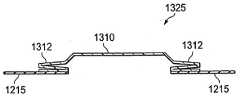
도 13을 참조하면, 드레이프(1325), 또는 커버는 주름부(1310)를 포함하고, 상기 주름부는 드레이프(1310) 상의 중심에 위치된다. 주름부(1310)는 탄성 또는 비탄성 물질로 구성될 수 있다. 주름부(1310)는 하나 이상의 물결 주름부들(1312), 또는 리지들도 포함한다. 물결 주름부들은 주름부(1310)의 일부 측 또는 모든 측 상에 위치될 수 있다. 또한, 도 13이 주름부(1310)의 각 측 상에 하나의 물결모양을 도시하고 있지만, 주름부(1310)의 각 측은 수많은 물결 주름부들을 포함할 수 있고, 벨로우즈와 같은 구조물을 형성할 수 있다. 주름부(1310)의 주름진 구성은, 밑에 있는 감압 드레싱에 액체가 저장될 시에 주름부(1310)가 연장되도록 한다.Referring to FIG. 13, the
도 11-13의 드레이프들(1125 및 1325)은 유체 수집을 수용하기 위해 감압 드레싱에 저장하기 위해 연장될 수 있다. 드레이프들(1125 및 1325)이 연장 전에, 연장 동안, 그리고 연장 후에 드레싱에 감압을 유지할 수 있다는 주목도 중요하다.
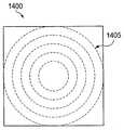
도 14 및 15를 참조하여, 계면층들(1400 및 1500)은 예시적인 실시예들에 따라서 도시된다. 계면층들(1400 및 1500)은 키스-컷 천공들(kiss-cut perforations)(1405 및 1505)을 포함하는 절개구조형 시트 폼 물질(tearable sheets foam material)이고, 이때 상기 키스-컷 천공들은 감압 드레싱(104)과 같은 드레싱에서의 사용을 위해 계면층들(1400 및 1500)의 절개 및 치수 정량을 쉽게 가능케 한다. 일 예에서, 계면층들(1400 및 1500)이 키스-컷될 시에, 컷팅 다이(cutting die)는 폼 물질의 두께를 통하여 대부분 침투되지만, 완전하게 침투되는 것은 아니다. 이는 절개되기에 약한 통로를 따라 구비되면서, 여전히 폼이 형상을 유지하도록 한다. 도 14에서, 키스-컷 천공들(1405)은 일련의 동축원들이다. 적당하게 치수화된 계면층은 동축원들 중 하나를 따라 절개될 수 있다. 도 15에서, 키스-컷 천공(1505)은 연속된 나선형과 같은 천공이다. 키스-컷 천공(1505)은, 드레싱과 함께 사용되기 전에 계면층을 치수화하기 위한 필요에 따라 이 연속된 천공을 따라 절개될 수 있다.14 and 15,
키스-컷 천공들(1405 및 1505)은 약하게 된 통로를 구비하고, 상기 통로를 따라 계면층이 절개될 수 있다. 계면층들(1400 및 1500)의 일부가 드레싱에서 사용될 시에, 계면층은 잔류한 일부 천공들을 여전하게 가질 수 있다. 그러나, 이러한 천공들을 가짐에도 불구하고, 계면층은 여전하게 원하는 형상을 유지할 수 있고, 본원에서 기술된 계면층의 기능을 효과적으로 실행할 수 있다.The kiss-
도 16을 참조하여, 감압 드레싱의 예의 특성을 보여주는 그래프(1600)가 도시된다. 그래프(1600)는 유체가 시간당 약 2 밀리미터로 첨가되는 감압 드레싱의 계면층에서 시간 함수로서 계측된 압력의 강하를 제시한다. 특히, 그래프(1600)는, 약 8 ㎠ 이고 테스트 동안 큰 관에 부착된 2차원 고흡수성 섬유층 드레싱을 가진 HME 폼을 포함하는 드레싱의 계면층에서 계측된 압력을 제시한다. 테스트를 걸쳐 드레싱에 가해진 감압은 125 mmHg로 일정하다. 시간이 경과되고, 드레싱이 유체로 채워짐에 따라, 압력은 결국 계면층에서 강하하고, 이때에 드레싱은 더 이상 감압을 적절하게 매니폴드할 수 없다. 그래프(1600)는 단지 하나의 특별한 감압 드레싱의 특성을 나타내고, 본원에 기술된 드레싱의 다른 예시적인 실시예들은 그래프(1600)에 나타난 특성과는 다른 특성을 보여줄 수 있다.Referring to FIG. 16, a
도 17을 참조하여, 예시적인 실시예에 따른 드레싱(1700)은 계면층(1715)을 포함한다. 도 2의 계면층(220)과 달리, 계면층(1715)은 드레싱의 다른 층들에 비해 보다 큰 크기를 가진다. 드레싱(1700)은 조직 계면층(1715) 상의 흡수층(228), 상기 흡수층(228) 상의 디버터층(232)을 포함한다. 감압 드레싱(104)과는 달리, 드레싱(1700)은 디버터층(232) 상의 또 다른 흡수층(1740)을 포함한다. 흡수층(1740)은 흡수층(228)과 유사하다. 흡수층(1740)은 드레싱(1700)의 흡수성을 증가시키기 위해 첨가될 수 있다. 흡수층(1740)은, 흡수층(228)을 지나 이동하거나, 상기 흡수층으로부터 나가는 액체를 포획하기 위해 사용될 수도 있다.Referring to FIG. 17, a dressing 1700, according to an exemplary embodiment, includes an
드레싱(1700)은 흡수층(1740) 상의 제 2 매니폴드층(236), 및 상기 제 2 매니폴드층(236) 상의 기액 분리기(240)를 포함한다. 드레싱(1700)은 기액 분리기(240) 상의 밀봉층(1724)(도 2의 밀봉층(222)과 유사함)도 포함한다. 밀봉층(1724)은 원형 개구부(1730)를 가지지만, 상기 원형 개구부(1730)는 임의의 형상일 수도 있다. 드레싱(1700)은 관형 어댑터(1740) 및 커버(244)도 포함할 수 있다. 관형 어댑터(1740)는 낮은 측면 돔 형상 또는 임의의 다른 형상일 수 있다.The dressing 1700 includes a
일 실시예에서, 조직 부위에 접촉되도록 구성된 드레싱(1700)의 구성요소는 조직 계면층(1715), 밀봉층(1724) 및 커버(244)이다. 그러나, 드레싱(1700)의 구성요소들은 치수화될 수 있고, 그 결과, 상기 구성요소들 중 임의의 것은 조직 부위와 접촉될 수 있다.In one embodiment, the components of the dressing 1700 configured to contact the tissue site are the
또 다른 예시적인 실시예에서, 방법은, 조직 부위에 위치된 드레싱에 있는 유체를 수집하기 위해 제공된다. 상기 방법은 드레싱을 통하여 조직 부위에 감압을 가하는 단계, 조직 부위로부터 액체를 흡수하는 단계, 및 드레싱에 있는 액체를 저장하는 단계를 포함한다. 방법은 액체가 드레싱에서 나가지 못하도록 하는 단계를 더 포함한다. 일 실시예에서, 조직 부위로부터 액체를 흡수하는 단계는 본원에서 기술된 흡수층들과 유사한 흡수층으로 달성된다. 방법은 흡수층과 연관된 흡수 효율을 증가시키기 위해 감압을 흡수층의 대상 영역으로 전화시키는 단계를 더 포함할 수 있다. 대상 영역으로의 감압 전환은, 흡수층이 감압을 분배할 수 있는 시간량을 증가시킬 수도 있다.In another exemplary embodiment, a method is provided for collecting a fluid in a dressing located at a tissue site. The method includes applying pressure to the tissue site through the dressing, absorbing liquid from the tissue site, and storing the liquid in the dressing. The method further includes preventing liquid from leaving the dressing. In one embodiment, absorbing the liquid from the tissue site is accomplished with an absorbent layer similar to the absorbent layers described herein. The method may further comprise converting the reduced pressure into the target region of the absorbent layer to increase the absorbent efficiency associated with the absorbent layer. The reduced pressure conversion to the target region may increase the amount of time the absorber layer can distribute the reduced pressure.
본원에서 기술된 감압 드레싱들의 예시적인 실시예들은, 흡수층이 유체를 흡수할 시에 심지어 감압 분배가 유지되는 것을 확보하기 위해, 디버터층을 포함할 수 있다. 디버터층은 드레싱에서 흡수성 물질의 효과적인 사용도 촉진시킨다. 예시적인 실시예들은 다공성 소수성 필터도 포함할 수 있고, 이때 상기 다공성 소수성 필터는 드레싱이 삼출액과 같은 액체를 허용하지 못하게 하고, 관에 들어가지 못하게 하며, 그리고 압력 분배를 확보하는데 도움을 준다. 예시적인 실시예들에서 층들의 시퀀스 및 드레싱의 구성은 조직 부위로의 감압의 전달과 조합하여 드레싱의 최적 흡수성을 확보하는데 도움을 준다.Exemplary embodiments of the reduced pressure dressings described herein may include a diverter layer to ensure that the reduced pressure distribution is maintained even when the absorbent layer absorbs the fluid. The diverter layer also promotes the effective use of the absorbent material in the dressing. Exemplary embodiments may also include a porous hydrophobic filter, wherein the porous hydrophobic filter prevents the dressing from accepting liquids, such as effluents, prevents entry into the tube, and secures pressure distribution. In exemplary embodiments the sequence of layers and the configuration of the dressing helps to ensure optimal absorbency of the dressing in combination with the delivery of reduced pressure to the tissue site.
현재, 상처 드레싱들은 축축한 상처 환경을 유지하는데 액체를 흡수하기 위해 설계되는 한편, 냉침(maceration)의 위험을 최소화시키지만, 그러나 감압을 적절하게 매니폴드하기에는 적합하지 않다. 감압과 함께 현재 사용되지 않은 현재 드레싱들은 압력을 조직 부위에 정상적으로 전달되지 않는다. 현재 이러한 드레싱들은 유체를 흡수하기 위해서만 설계되고, 정기적으로 변화된다. 예시적인 실시예들에서 기술된 드레싱들은, 치료를 제공하고 감압이 있든지 없든지 간에 월등한 흡수성 능력을 제공하기 위해 구성되고, 그리고 심각성이 낮은 상처 및 삼출액이 적은 상처를 포함하여 매우 다양한 상처에 적용될 수 있다. 예시적인 실시예들에 기술된 드레싱들은 드레싱의 흡수성에 영향을 주지 않고 감압 조직 치료를 가능케 할 것이다.Currently, wound dressings are designed to absorb liquids to maintain a moist wound environment, while minimizing the risk of maceration, but are not suitable to adequately manifold decompression. Current dressings not currently used with decompression do not normally deliver pressure to the tissue site. Currently these dressings are only designed to absorb fluids and change regularly. The dressings described in the exemplary embodiments are configured to provide treatment and to provide superior absorbent capacity, with or without decompression, and to a wide variety of wounds, including low severity wounds and low effusion wounds. Can be applied. Dressings described in the exemplary embodiments will allow for decompression tissue treatment without affecting the absorbency of the dressing.
디버터층과 같은 구성요소들에 의해 제공된 전환 없이, 액체는 흡수층에 의해 흡수될 수 있고, 삼출액의 지점 주위의 제한된 영역으로 집중될 수 있다. 이는 사용되지 않은 흡수층의 양을 크게 할 수 있다. 예를 들면, 125 mmHg의 감압원이 감압 드레싱에 연결될 시에, 흡수성 물질은 흡수된 액체의 일부를 방출할 수 있고, 흡수성 영역의 나머지를 우회할 수 있고, 감압원과 드레싱이 연결된 관으로 직접 인출될 수 있다. 이 지점에서, 드레싱은 더 많은 액체를 흡수하기 위해 중지될 수 있고, 액체가 관에 들어감에 따라, 조직 부위에 감압을 전달시키는 드레싱의 성능은 손상된다. 또한, 이는, 대상 유체량 중 적은 일부(fraction)만이 흡수될 시에 일어날 수 있다. 그러나, 본원에서 기술된 디버터층 및 다른 층들을 사용함으로써, 흡수층들의 효율은 증가될 수 있고, 그 결과, 감압 드레싱은 액체를 더 많이 흡수하고, 장시간 동안 감압을 매니폴드할 수 있다.Without the conversion provided by components such as the diverter layer, the liquid can be absorbed by the absorber layer and concentrated in a limited area around the point of the effluent. This can increase the amount of the absorbent layer that is not used. For example, when a 125 mmHg decompression source is connected to the decompression dressing, the absorbent material may release some of the absorbed liquid, bypass the rest of the absorbent region, and directly into the tube to which the decompression source and the dressing are connected. Can be withdrawn. At this point, the dressing can be stopped to absorb more liquid, and as the liquid enters the canal, the dressing's ability to deliver reduced pressure to the tissue site is impaired. This may also occur when only a small fraction of the amount of fluid of interest is absorbed. However, by using the diverter layer and other layers described herein, the efficiency of the absorber layers can be increased, as a result of which the pressure-sensitive dressing can absorb more liquid and manifold the pressure-reduction for a long time.
본원에서 기술된 감압 드레싱의 구성요소들은 이행에 따라서 변경될 수 있는 비제한적인 공간 구성에서 제시된다. 도면에는 특별한 순서로 감압 드레싱들의 구성요소들이 도시되지만, 상기 구성요소들은 이행에 따른 임의의 순서를 가질 수 있다. 이와 유사하게, 임의의 특별한 구성요소의 포함 또는 배제는 특별한 적용에 따라서 변화될 수 있다.
The components of the reduced pressure dressing described herein are presented in a non-limiting spatial configuration that can be altered upon implementation. While the figures show the components of the pressure reducing dressings in a particular order, the components can have any order according to implementation. Similarly, the inclusion or exclusion of any particular component may vary depending on the particular application.
통합된 펌프를 가진 드레싱Dressing with integrated pump
도 1-17의 감압 드레싱들 및 구성요소들은 드레싱 외부에 있는 감압원에 연결되도록 구성된 바와 같이 기술된다. 그러나, 본원에 기술된 감압 드레싱들은 통합된 펌프, 즉 드레싱의 층들 내 또는 상기 층들 사이에서 위치된 펌프를 통합시킬 수도 있어서, 드레싱의 층들을 통해 감압을 조직 부위에 전달시킨다.The reduced pressure dressings and components of FIGS. 1-17 are described as configured to be connected to a reduced pressure source external to the dressing. However, the reduced pressure dressings described herein may incorporate an integrated pump, i.e., a pump located in or between the layers of the dressing, to deliver a reduced pressure to the tissue site through the layers of the dressing.
도 18을 참조하여, 예시적인 실시예에 따른 감압 치료 시스템(1800)은 환자의 조직 부위(1808)에서 위치된 감압 드레싱(1804)을 포함한다. 감압 드레싱(1804)은 감압 펌프(1810)를 포함하고, 상기 감압 펌프는 감압 드레싱(1804)내로 통합된다. 감압 펌프(1810)에 추가하여, 다른 구성요소들은 센서, 프로세싱 유닛, 제어 유닛, 알람 표시기들, 메모리, 데이터베이스, 소프트웨어를 포함하지만 이에 제한되지 않고, 드레싱에 통합될 수도 있다. 추가적으로, 감압 드레싱(1804)은 드레싱(1804) 내의 구성요소들과 드레싱(1804)의 외부에 있을 수 있는 구성요소들 사이에서, 유체 연통을 가능케 하는 인터페이스(무선 또는 유선)를 포함할 수 있다. 제한되지 않은 일 예에서, 인터페이스는 USB 포트일 수 있다. 외부 구성요소들은, 조직 부위(1808)로의 감압 치료 적용을 더 용이하게 하는 제어 유닛들, 디스플레이 유닛들, 배터리 충전기들 및 사용자 인터페이스들을 포함하지만 이들에 제한되지 않는다. 감압 펌프(1810)를 이용하여, 감압 드레싱(1804) 및 조직 부위(1808)로의 감압 전달은 조직 부위로부터 삼출액의 배수를 유지시킴으로써, 신규 조직 성장을 촉진시키고, 조직 부위를 둘러싸는 조직에 혈류를 증가시키며, 그리고 조직 부위에서 마이크로스트레인을 생성시킨다.Referring to FIG. 18, a
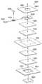
도 19 및 20을 참조하여, 감압 드레싱(1804)은, 조직 부위(1808)에서 위치되도록 구성된 계면층(1920), 및 조직 부위(1808) 주위에서 감압 드레싱(1804)을 밀봉하는 밀봉층(1922)을 포함한다. 제 1 매니폴드층(1924)은, 감압을 계면층(1920) 및 조직 부위(1808)에 분배시키기 위해, 계면층(1920)과 유체 연통하게 위치된다. 흡수층(1928)은, 제 1 매니폴드층(1924), 계면층(1920) 및 조직 부위(1808) 중 적어도 하나로부터 액체를 흡수하기 위해, 제 1 매니폴드층(1924)과 유체 연통하게 위치된다. 디버터층(1932)은 흡수층(1928)에 인접하여 위치된다. 제 2 매니폴드층(1936)은 디버터층(1932)과 유체 연통하게 위치되고, 기액 분리기(1940)는 제 2 매니폴드층(1936)에 인접하여 위치된다. 커버(1944), 또는 드레이프는 제 2 기액 분리기(1940)에 인접하여 위치된다. 표시기 및 냄새 필터는 감압 드레싱(1804) 내에 위치될 수도 있다.Referring to FIGS. 19 and 20, the pressure reducing dressing 1804 includes an
감압 드레싱(1804)의 다수 층들은 본원에 기술된 다른 감압 드레싱들의 층들에 대한 형상, 크기, 위치 및 기능과 유사하다. 상기에서 나열된 드레싱(1804)의 층들과 더불어, 감압 드레싱(1804)은 펌프(1810)를 포함하고, 상기 펌프는 기액 분리기(1940)와 커버(1944) 사이의 드레싱에 통합될 수 있다. 펌프(1810)는 충분히 작고 가벼운 마이크로펌프일 수 있고, 그 결과, 통합된 감압 드레싱(1804)은 조직 부위(1808) 상에서 유지될 수 있다. 또한, 펌프(1810)의 크기 및 무게는, 통합된 감압 드레싱(1804)이 조직 부위(1808)를 잡아당기지 못하도록, 그렇지 않다면 상기 조직 부위에 역효과를 주지 않도록 해야 한다. 일 실시예에서, 펌프(1810)는, 참조로서 본원에 병합되는, WO 2006/111775로서 공보된 국제 특허 출원 제PCT/GB2006/001487호에 기술된 압전기 액츄에이터와 유사한 압전기 액츄에이터를 가진 디스크 펌프일 수 있다. 대안적인 실시예에서, 펌프(1810)는 다양한 유체를 펌핑하도록 사용된 연동 펌프(peristaltic pump)일 수 있다. 대안 펌프 기술들이 이용될 수 있고, 펌프의 회전형, 선형, 또는 다른 구조도 이용될 수 있다는 것을 이해하여야 한다.Many of the layers of pressure reducing dressing 1804 are similar in shape, size, location, and function to the layers of other pressure reducing dressings described herein. In addition to the layers of the dressing 1804 listed above, the reduced pressure dressing 1804 includes a
펌프(1810)는 상처 치료를 위해 "치료"되는데 감압이 충분하게 생성되도록 사용될 수 있다. 일 실시예에서, 펌프(1810)는 감압 치료의 연이은 적용이 가능하도록, 충분한 유동, 진공 및 동작 수명 특성을 가진다. 유동은 약 5-1000 ml/min의 범위일 수 있고, 진공은 약 50-200 mmHg의 범위일 수 있고, 그리고 연이은 동작 수명은 20 시간 이상으로 지속될 수 있다. 대안적인 범위가 통합된 감압 드레싱(1804)의 구성, 상처의 크기, 상처의 유형 등에 따라서 이용될 수 있다는 것을 이해하여야 한다. 일 실시예에서, 다수의 펌프들은 필요에 따라 증가된 유량 또는 진공 레벨을 전달하기 위해 단일 드레싱에서 위치될 수 있다. 대안적으로, 상이한 동작 성능 및 설명을 가진 펌프들의 선택은 사용자 또는 의사에 의해 손으로 유지될 수 있어서, 특별 조직 부위에 대한 펌프 및 드레싱 결합의 최적화를 가능케 한다.
펌프(1810)는 상처 삼출액의 수집을 위한 외부 캐니스터들 및 도관들을 피하기 위해 드레싱내에 배치된다. 펌프(1810)는 감압 드레싱(1804)의 공기를 방출하거나 상기 감압 드레싱 외부로 배출시키기 위해 밸브(1950) 또는 배출구 포트를 포함할 수 있다. 밸브(1950)가 사용되면, 밸브(1950)는 커버(1944)의 개구부(1960)와 유체 연통될 수 있거나, 또는 커버(1944)의 개구부(1960) 내에 위치될 수 있다. 대안적으로, 커버(1944)는 펌프(1810)의 배출구 포트 주위에서 밀봉될 수 있고, 그 결과, 펌프(1810)로부터의 가스는 개구부(1960)를 통해 직접 배출할 수 있다. 도 18-20에서 도시된 실시예에서, 펌프(1810)의 밸브 또는 배출구 포트는 상처 드레싱에 공기를 첨가하는 것을 피하기 위해 소수성 필터로부터 떨어진 방향으로 배향된다. 공기는 일-방향 밸브를 포함할 수 있는 커버(1944)의 개구부(1960)를 통해 배출된다. 대안적으로, 감압을 유지하기 위한 커버(1944)의 성능이 영향을 미치지 않는 한, 공기 또는 다른 가스는 커버(1944)의 가스 침투성 부분을 통해 배출될 수 있다.
압전기-구동 펌프가 드레싱에 사용될 시에, 펌프와 연관된 압전기 액츄에이터는 버저(buzzer) 또는 진동 경고 시스템으로서 작동하기 위해 서로 다른 주파수로 구동될 수 있다. 상기 경고 시스템은 알람 조건을 사용자에게 경고하기 위해 사용될 수 있고, 이때 상기 알람 조건은 예를 들면, 드레싱에서의 누출 존재, 센서에 의해 계측된 감압의 변화, 표시기에 의해 지시될 수 있는 바와 같이 드레싱이 최대 수용량을 흡수할 때의 표시, 또는 하나 이상의 층이 감압을 더 이상 효과적으로 매니폴드하지 못할 때의 표시이다.When piezo-driven pumps are used in dressings, the piezoelectric actuators associated with the pumps can be driven at different frequencies to act as buzzers or vibration alert systems. The warning system can be used to alert the user to an alarm condition, where the alarm condition is for example dressing as indicated by the presence of a leak in the dressing, a change in the decompression measured by the sensor, an indicator. It is an indication when absorbing this maximum capacity, or when one or more layers can no longer effectively manifold the decompression.
제어 전자부(2024)는 펌프(1810)의 동작을 제어하기 위해 이용될 수 있다. 제어 전자부(2024)는 아날로그 및/또는 디지털일 수 있고, 펌프(1810)가 동작하는 속도 또는 듀티 사이클(duty cycle)을 조절하는 조절기(미도시)로 구성될 수 있다. 또한, 제어 전자부(2024)는 센서들 또는 스위치들(미도시)로부터 감지 신호들을 수신하는 제어기(미도시)로 구성될 수 있다. 센서들은, 펌프(1810)를 관리하고 제어하는데 이용될 수 있는 압력, 온도, 수분, 화학 성질, 냄새, 또는 임의의 다른 파라미터와 같은 파라미터를 감지하기 위해 통합된 감압 드레싱(1804)에 거쳐 배치될 수 있다. 일 실시예에서, 제어 전자부(2024)는 컴퓨터 프로세서를 포함한다. 대안적으로, 제어 전자부(2024)는 프로그램가능한 게이트 어레이를 포함할 수 있다. 여전하게, 제어 전자부(2024)는 아날로그 전자 구성요소들로 형성될 수 있다. 제어 전자부(2024)가 본원에 도시된 바와 같이, 기능성을 실행시키기 위해 디지털 및/또는 아날로그 성분의 형태를 포함할 수 있다는 것을 이해하여야 한다.The
기술 분야를 이해함에 따라서, 감압 상처 치료를 실행하는 것에 관해 4 가지의 기본 파라미터가 있고, 이는 (i) 낮은 압력, (ⅱ) 과잉 누출, (ⅲ) 흡수층의 레벨 및 (ⅳ) 배터리 상태를 포함한다. 따라서, 제어 전자부(2024)는, 파라미터가 안전 범위를 벗어날 시, 의사, 환자, 또는 가족에게 통보를 주기 위해, 스피커(미도시), 진동기(미도시), 또는 발광 다이오드(LED)와 같은 발광 장치(미도시)를 사용하여, 4 가지의 기본적인 파라미터들 각각을 감시하기 위해 사용될 수 있고, 알람 신호(예를 들면, 높은 피치의 경보음(high-pitched beep), 진동 또는 광)를 발생시키는 전자기기들을 포함할 수 있다. 예를 들면, 상처 부위에서의 압력이 치료 레벨 이하인 경우, 연이은 음이 발생될 수 있다. 또 다른 예로서, 흡수층(1928)이 흠뻑 젖으면, 경보음은 연속적으로 발생될 수 있다. 여전하게, 배터리가 특정 전압 레벨 이하로 강하되면, 서로 다른 주파수가 발생되고/발생되거나, LED가 턴 온될 수 있다. 서로 다른 다양한 알람 신호는 의사가 특별한 작용을 취하게 하는 통보를 주기 위해 구현될 수 있다.As understood in the art, there are four basic parameters regarding performing decompression wound treatment, including (i) low pressure, (ii) excess leakage, (i) level of absorbent layer and (i) battery condition. do. Accordingly, the
배터리(2026)는 전력을 펌프(1810) 및 제어 전자부(2024)에 제공하기 위해 이용될 수 있다. 배터리(2026)는 상술된 바와 같이, 통합된 감압 드레싱(1804)의 무게 및 크기를 수용하기 위해, 임의의 크기 및 형상 구조를 가질 수 있고, 중합체와 같은 임의의 물질일 수 있다. 일 실시예에서, 배터리(2026)는 충전가능할 수 있다. 또 다른 실시예에서, 배터리(2026)는 통합된 감압 드레싱(1804) 내에서 또는 상기 감압 드레싱 외부에 배치될 수 있고, 대체 또는 재충전을 손쉽게 가능케 하는 방식으로 위치될 수 있다. 일 실시예에서, 배터리(2026)는 저 전원 레벨을 판별하기 위해 제어 전자부(2024)에 의해 감시되는 전압 레벨 센서(미도시)로 구성될 수 있다. 일 실시예에서, 배터리(2026)는 펌프(1810)와 직접 연결될 수 있다. 대안적으로, 배터리(2026)는 펌프(1810)를 구동하기 위해 배터리(2026)로부터 전원을 사용하는 제어 전자부(2024)에 연결될 수 있다. 제어 전자부(2024)는 펌프(1810)를 구동하기 위해 PWM(pulsewidth modulated) 신호와 같은, 연속된 전원, 변조된 전원을 제공할 수 있다.The
밀봉층(1922)은 커버층(1944)에 접착되거나, 그렇지 않으면 상기 커버층에 연결되고, 이때 상기 커버층은 통합된 감압 드레싱(1804)을 드레이프하기 위해, 또는 덮기 위해 사용된다. 밀봉층(1922)은 환자의 상처 주위에 있는 피부와 진공 밀봉을 형성하기 위해 충분히 강한, 우수하거나(aggressive) 의료 등급용 접착제 물질을 포한다. 밀봉층(1922)은, 소수성 필터(2020) 또는 다른 층들로서 기하학적인 파라미터들보다 다소 큰 개구부(2032)를 가진 밴드(band)일 수 있고, 그 결과, 커버층(2030)은 환자의 상처 부위 주위에 있는 피부와 접촉할 수 있다. 커버층(2030)은 공기 및 액체와 같은 유체에 대해 불침투성 특성을 가질 수 있다. 일 실시예에서, 커버층(2030)은 통합된 감압 드레싱(1804)으로부터 방출되도록, 펌프(1810)로부터 배출될 수 있는 밸브(2034)를 포함한다. 밸브(2034)는 커버층(2030)을 통해 통합된 감압 드레싱(1804)으로 들어가는 유체를 최소화시키기 위한 일-방향 밸브일 수 있다.
또 다른 실시예에서, 밀봉층(1922)은 디버터층(1932)에 접착될 수 있고, 상기 디버터층(1932)은 커버(1944)에 접착되어 상부 드레싱부 및 하부 드레싱부를 구현한다. 상부 드레싱부는 커버(1944), 펌프(1810) 및 이에 관련된 구성요소들, 기액 분리기(1940), 제 2 매니폴드층(1936) 및 디버터층(1932)을 포함할 수 있다. 하부 드레싱부는 흡수층(1928), 제 1 매니폴드층(1924), 밀봉층(1922) 및 계면층(1920)을 포함할 수 있다. 일 실시예에서, 감압 드레싱은, 상기 드레싱이 유체의 최대 수용량을 흡수하면, 하부 드레싱부의 대체물을 가능케 하도록 구성될 수 있다. 상부 드레싱부는, 하부 드레싱부가 대체된 후에 재사용될 수 있다. 이는 여러 번의 펌프(1810) 사용을 가능케 하는 반면, 드레싱의 처분가능한 부분들은 대체될 수 있다. 또 다른 실시예에서, 펌프(1810), 제어 전자부(2024) 및 배터리(2026)는 재사용되기 위해 드레싱으로부터 제거될 수 있고, 드레싱의 잔류층들은 대체될 수 있다. 여전히 또 다른 실시예에서, 흡수층(1928)만이 대체될 수 있다. 또 다른 실시예에서, 흡수층(1928) 및 계면층(1920)만이 대체될 수 있다.In another embodiment, the
숯 필터(2036)는 상처 부위에서 생성된 냄새, 및 통합된 감압 드레싱(1804)으로부터 퍼진 냄새를 줄이기 위해 통합된 감압 드레싱(1804)에서 이용될 수 있다. 숯 필터(2036)는, 배출물을 통합된 감압 드레싱(1804)으로부터 방출하기 전에, 펌프(1810)로부터의 배출물을 여과시키기 위해 펌프(1810)로부터의 밸브 또는 다른 출력 벤트(output vent) 상에 배치될 수 있다. 숯 필터(2036)가 대안적으로 펌프(1810) 상 또는 하에서 구성 및 배치될 수 있다는 것을 이해하여야 한다. 여전하게는, 숯 필터 사용보다 오히려, 숯이 상기 통합된 감압 드레싱(1804)에 이용되는 서로 다른 층들 중 일부 또는 모두에 통합될 수 있다.The
또 다른 예시적인 실시예에서, 조직 부위에 위치된 드레싱에서의 액체를 수집하는 방법은 드레싱내에 위치된 펌프를 사용하여 감압을 발생시키는 단계를 포함한다. 액체는 조직 부위로부터 흡수되고, 드레싱에 저장된다. 액체는 펌프에 들어가지 못한다. 방법은 드레싱 내에 감압을 유지시키는 단계 및 펌프로부터 드레싱 외부로 가스를 배출하는 단계를 더 포함할 수 있다.In another exemplary embodiment, a method of collecting liquid in a dressing located at a tissue site includes generating a reduced pressure using a pump located in the dressing. The liquid is absorbed from the tissue site and stored in the dressing. Liquid does not enter the pump. The method may further include maintaining a reduced pressure in the dressing and evacuating the gas from the pump out of the dressing.
중요한 이점을 가진 본 발명이 제공된다는 것을 상술된 바로부터 명백해져야 한다. 본 발명이 단지 본 발명의 일부 형태만을 제시하였지만, 본 발명은 단지 이에 제한되지 않고, 본 발명의 기술 사상으로부터 벗어남 없이 다양한 변화 및 변형이 수용될 수 있다.It should be apparent from the foregoing that the present invention with important advantages is provided. Although the present invention has presented only some forms of the present invention, the present invention is not limited thereto, and various changes and modifications can be accommodated without departing from the spirit of the present invention.
Claims (65)
Translated fromKorean상기 조직 부위에 위치되도록 구성된 계면층;
상기 계면층 및 상기 조직 부위 중 적어도 하나로부터 액체를 흡수하기 위해 상기 계면층과 유체 연통하는 흡수층;
상기 조직 부위에 감압을 전달하기 위해 상기 흡수층과 유체 연통하는 펌프;
상기 조직 부위에 감압을 유지시키기 위해 상기 펌프, 상기 흡수층 및 상기 계면층 상에 위치된 커버; 및
상기 펌프에서 액체가 나가지 못하도록 상기 흡수층과 상기 펌프 사이에 위치된 기액 분리기를 포함하는 것을 특징으로 하는 감압 드레싱.In a decompression dressing in which decompression treatment is applied to a tissue site,
An interfacial layer configured to be located at the tissue site;
An absorbent layer in fluid communication with the interfacial layer to absorb liquid from at least one of the interfacial layer and the tissue site;
A pump in fluid communication with the absorbent layer to deliver a reduced pressure to the tissue site;
A cover located on the pump, the absorbent layer and the interfacial layer to maintain a reduced pressure at the tissue site; And
And a gas-liquid separator positioned between the absorbent layer and the pump to prevent liquid from exiting the pump.
상기 계면층은 소수성인 것을 특징으로 하는 감압 드레싱.The method of claim 1,
Pressure-sensitive dressing, characterized in that the interfacial layer is hydrophobic.
상기 흡수층은 고흡수성 섬유를 포함하는 것을 특징으로 하는 감압 드레싱.The method of claim 1,
Pressure absorbing dressing, characterized in that the absorbent layer comprises superabsorbent fibers.
상기 커버와, 상기 조직 부위에 있는 또는 상기 조직 부위 근처의 조직 사이에서 위치된 밀봉층을 더 포함하는 것을 특징으로 하는 감압 드레싱.The method of claim 1,
And a sealing layer positioned between the cover and tissue at or near the tissue site.
상기 펌프는 압전기-구동 마이크로펌프인 것을 특징으로 하는 감압 드레싱.The method of claim 1,
Said pump is a piezo-driven micropump.
상기 드레싱 내에 위치되고 상기 펌프와 동작적으로 연결된 제어 전자기기들 및 배터리를 더 포함하는 것을 특징으로 하는 감압 드레싱.The method of claim 1,
Further comprising a battery and control electronics located in the dressing and operatively connected to the pump.
상기 펌프로부터 가스의 배출을 가능케 하기 위해, 상기 커버에 있는 개구부를 더 포함하는 것을 특징으로 하는 감압 드레싱.The method of claim 1,
And an opening in the cover to enable the evacuation of the gas from the pump.
상기 펌프의 배출구 포트와 유체 연통하는 냄새 필터를 더 포함하는 것을 특징으로 하는 감압 드레싱.The method of claim 1,
And an odor filter in fluid communication with the outlet port of the pump.
상기 조직 부위에 위치되도록 구성된 계면층;
상기 계면층 및 상기 조직 부위 중 적어도 하나로부터 액체를 흡수하기 위해 상기 계면층과 유체 연통하는 흡수층;
상기 조직 부위에 감압을 전달하기 위해 상기 흡수층과 유체 연통하는 펌프;
상기 흡수층과 상기 펌프 사이의 디버터층(상기 디버터층은 상기 펌프에서 상기 흡수층으로 감압을 전달하기 위해 복수의 개구부를 포함함);
상기 조직 부위에서 감압을 유지시키기 위해 상기 펌프, 상기 디버터층, 상기 흡수층 및 상기 계면층 상에 위치된 커버; 및
상기 펌프에서 액체가 나가지 못하도록 상기 디버터층과 상기 펌프 사이에 위치된 기액 분리기를 포함하는 것을 특징으로 하는 감압 드레싱.In a decompression dressing in which decompression treatment is applied to a tissue site,
An interfacial layer configured to be located at the tissue site;
An absorbent layer in fluid communication with the interfacial layer to absorb liquid from at least one of the interfacial layer and the tissue site;
A pump in fluid communication with the absorbent layer to deliver a reduced pressure to the tissue site;
A diverter layer between the absorbent layer and the pump, the diverter layer including a plurality of openings for delivering a reduced pressure from the pump to the absorbent layer;
A cover located on said pump, said diverter layer, said absorbent layer and said interfacial layer to maintain a reduced pressure at said tissue site; And
And a gas-liquid separator positioned between the diverter layer and the pump to prevent liquid from exiting the pump.
상기 계면층은 소수성인 것을 특징으로 하는 감압 드레싱.The method of claim 9,
Pressure-sensitive dressing, characterized in that the interfacial layer is hydrophobic.
상기 흡수층은 고흡수성 섬유를 포함하는 것을 특징으로 하는 감압 드레싱.The method of claim 9,
Pressure absorbing dressing, characterized in that the absorbent layer comprises superabsorbent fibers.
상기 디버터층의 표면적은 상기 커버의 표면적보다 큰 것을 특징으로 하는 감압 드레싱.The method of claim 9,
And the surface area of the diverter layer is larger than the surface area of the cover.
상기 디버터층의 표면적은 상기 커버의 표면적보다 크고; 그리고
상기 커버의 적어도 일부는 상기 디버터층에 접착 방식으로 연결되고, 상기 디버터층의 적어도 일부는 상기 조직 부위를 둘러싸는 조직에 연결되는 것을 특징으로 하는 감압 드레싱.The method of claim 9,
The surface area of the diverter layer is larger than the surface area of the cover; And
At least a portion of the cover is adhesively connected to the diverter layer, and at least a portion of the diverter layer is connected to a tissue surrounding the tissue site.
상기 디버터층과, 상기 조직 부위를 둘러싸는 조직 사이에 위치된 밀봉층을 더 포함하는 것을 특징으로 하는 감압 드레싱.The method of claim 13,
And a sealing layer positioned between the diverter layer and the tissue surrounding the tissue site.
상기 디버터층의 개구부들은 상기 디버터층의 적어도 하나의 주변 에지의 근처에 위치된 것을 특징으로 하는 감압 드레싱.The method of claim 9,
Openings in the diverter layer are positioned near at least one peripheral edge of the diverter layer.
상기 개구부들 중 적어도 하나는 상기 개구부들 중 또 다른 것보다 큰 것을 특징으로 하는 감압 드레싱.The method of claim 9,
At least one of said openings is larger than another of said openings.
상기 개구부들 중 적어도 하나는 수분과 접촉하도록 더 작게 구성되는 것을 특징으로 하는 감압 드레싱.The method of claim 9,
At least one of said openings is configured to be smaller in contact with moisture.
상기 디버터층은 상기 디버터층의 표면 상에 복수의 리지들을 포함하여, 상기 리지들 사이에서 복수의 채널들을 정의하는 것을 특징으로 하는 감압 드레싱.The method of claim 9,
Wherein said diverter layer comprises a plurality of ridges on a surface of said diverter layer, defining a plurality of channels between said ridges.
상기 디버터층은 상기 흡수층의 흡수 능력이 보다 더 완전하게 이용되도록 하는 것을 특징으로 하는 감압 드레싱.The method of claim 9,
And said diverter layer allows the absorbent capability of said absorbent layer to be more fully utilized.
상기 디버터층은 상기 흡수층이 감압을 분배할 수 시간량을 증가시키는 것을 특징으로 하는 감압 드레싱.The method of claim 9,
And said diverter layer increases the amount of time said absorber layer can dispense the reduced pressure.
상기 디버터층은 가스가 침투가능한 것(gas permeable)을 특징으로 하는 감압 드레싱.The method of claim 9,
And said diverter layer is gas permeable.
상기 펌프는 압전기-구동 마이크로펌프인 것을 특징으로 하는 감압 드레싱.The method of claim 9,
Said pump is a piezo-driven micropump.
상기 드레싱 내에 위치되고 상기 펌프와 동작적으로 연결된 제어 전자기기들 및 배터리를 더 포함하는 것을 특징으로 하는 감압 드레싱.The method of claim 9,
Further comprising a battery and control electronics located in the dressing and operatively connected to the pump.
상기 펌프로부터 가스의 배출을 가능케 하기 위해, 상기 커버에 있는 개구부를 더 포함하는 것을 특징으로 하는 감압 드레싱.The method of claim 9,
And an opening in the cover to enable the evacuation of the gas from the pump.
상기 펌프의 배출구 포트와 유체 연통하는 냄새 필터를 더 포함하는 것을 특징으로 하는 감압 드레싱.The method of claim 9,
And an odor filter in fluid communication with the outlet port of the pump.
상기 조직 부위에 위치되도록 구성된 계면층;
상기 계면층 및 상기 조직 부위 중 적어도 하나로부터 액체를 흡수하기 위해 상기 계면층과 유체 연통하는 흡수층;
상기 흡수층에 인접한 디버터층(상기 디버터층은 실질적인 가스-불침투성 물질로 형성되고, 상기 디버터층은 상기 흡수층이 감압을 분배시킬 수 있는 시간량을 증가시키기 위해 상기 흡수층과 유체 연통하는 복수의 개구부들을 포함함);
상기 조직 부위에 감압을 전달하기 위해 상기 디버터층의 복수의 개구부들과 유체 연통하는 펌프;
상기 조직 부위에 감압을 유지시키기 위해 상기 펌프, 상기 디버터층, 상기 흡수층 및 상기 계면층 상에 위치된 커버; 및
상기 펌프에서 액체가 나가지 못하도록 상기 디버터층과 상기 펌프 사이에 위치된 기액 분리기를 포함하는 것을 특징으로 하는 감압 드레싱.In a decompression dressing in which decompression treatment is applied to a tissue site,
An interfacial layer configured to be located at the tissue site;
An absorbent layer in fluid communication with the interfacial layer to absorb liquid from at least one of the interfacial layer and the tissue site;
A diverter layer adjacent to the absorber layer, the diverter layer being formed of a substantially gas-impermeable material, the diverter layer being in fluid communication with the absorber layer to increase the amount of time the absorber layer can distribute the reduced pressure Openings of);
A pump in fluid communication with the plurality of openings in the diverter layer to deliver a reduced pressure to the tissue site;
A cover located on said pump, said diverter layer, said absorbent layer and said interfacial layer to maintain a reduced pressure at said tissue site; And
And a gas-liquid separator positioned between the diverter layer and the pump to prevent liquid from exiting the pump.
상기 계면층은 소수성인 것을 특징으로 하는 감압 드레싱.The method of claim 26,
Pressure-sensitive dressing, characterized in that the interfacial layer is hydrophobic.
상기 흡수층은 고흡수성 섬유를 포함하는 것을 특징으로 하는 감압 드레싱.The method of claim 26,
Pressure absorbing dressing, characterized in that the absorbent layer comprises superabsorbent fibers.
상기 커버와, 상기 조직 부위를 둘러싸는 조직 사이에 위치된 밀봉층을 더 포함하는 것을 특징으로 하는 감압 드레싱.The method of claim 26,
And a sealing layer positioned between the cover and the tissue surrounding the tissue site.
상기 디버터층의 표면적은 상기 커버의 표면적보다 큰 것을 특징으로 하는 감압 드레싱.The method of claim 26,
And the surface area of the diverter layer is larger than the surface area of the cover.
상기 디버터층의 표면적은 상기 커버의 표면적보다 크고; 그리고
상기 커버의 적어도 일부는 상기 디버터층에 접착 방식으로 연결되고, 상기 디버터층의 적어도 일부는 상기 조직 부위를 둘러싸는 조직에 연결되는 것을 특징으로 하는 감압 드레싱.The method of claim 26,
The surface area of the diverter layer is larger than the surface area of the cover; And
At least a portion of the cover is adhesively connected to the diverter layer, and at least a portion of the diverter layer is connected to a tissue surrounding the tissue site.
상기 디버터층과, 상기 조직 부위를 둘러싸는 조직 사이에 위치된 밀봉층을 더 포함하는 것을 특징으로 하는 감압 드레싱.The method of claim 31, wherein
And a sealing layer positioned between the diverter layer and the tissue surrounding the tissue site.
상기 디버터층의 개구부들은 상기 디버터층의 적어도 하나의 주변 에지의 근처에 위치된 것을 특징으로 하는 감압 드레싱.The method of claim 26,
Openings in the diverter layer are positioned near at least one peripheral edge of the diverter layer.
상기 개구부들 중 적어도 하나는 상기 개구부들 중 또 다른 것보다 큰 것을 특징으로 하는 감압 드레싱.The method of claim 26,
At least one of said openings is larger than another of said openings.
상기 개구부들 중 적어도 하나는 수분과 접촉하도록 더 작게 구성되는 것을 특징으로 하는 감압 드레싱.The method of claim 26,
At least one of said openings is configured to be smaller in contact with moisture.
상기 디버터층은 상기 디버터층의 표면 상에 복수의 리지들을 포함하여, 상기 리지들 사이에서 복수의 채널들을 정의하는 것을 특징으로 하는 감압 드레싱.The method of claim 26,
Wherein said diverter layer comprises a plurality of ridges on a surface of said diverter layer, defining a plurality of channels between said ridges.
상기 디버터층은 상기 흡수층의 흡수 능력이 보다 더 완전하게 이용되도록 하는 것을 특징으로 하는 감압 드레싱.The method of claim 26,
And said diverter layer allows the absorbent capability of said absorbent layer to be more fully utilized.
상기 디버터층은 상기 흡수층의 흡수 효율을 증가시키는 것을 특징으로 하는 감압 드레싱.The method of claim 26,
And said diverter layer increases the absorption efficiency of said absorbent layer.
상기 펌프는 압전기-구동 마이크로펌프인 것을 특징으로 하는 감압 드레싱.The method of claim 26,
Said pump is a piezo-driven micropump.
상기 드레싱 내에 위치되고 상기 펌프와 동작적으로 연결된 제어 전자기기들 및 배터리를 더 포함하는 것을 특징으로 하는 감압 드레싱.The method of claim 26,
Further comprising a battery and control electronics located in the dressing and operatively connected to the pump.
상기 펌프로부터 가스의 배출을 가능케 하기 위해, 상기 커버에 있는 개구부를 더 포함하는 것을 특징으로 하는 감압 드레싱.The method of claim 26,
And an opening in the cover to enable the evacuation of the gas from the pump.
상기 펌프의 배출구 포트와 유체 연통하는 냄새 필터를 더 포함하는 것을 특징으로 하는 감압 드레싱.The method of claim 26,
And an odor filter in fluid communication with the outlet port of the pump.
상기 조직 부위에 위치되도록 구성된 계면층;
상기 계면층과 유체 연통하게 위치된 제 1 매니폴드층;
상기 제 1 매니폴드층, 상기 계면층 및 상기 조직 부위 중 적어도 하나로부터 액체를 흡수하기 위해, 상기 제 1 매니폴드층과 유체 연통하는 흡수층;
실질적인 가스-불침투성 물질로 형성된 디버터층(상기 디버터층은 상기 흡수층과 유체 연통하는, 공간을 가진 복수의 개구부들을 포함함);
상기 디버터층과 유체 연통하는 제 2 매니폴드층;
상기 조직 부위에 감압을 전달하기 위해 상기 제 2 매니폴드층과 유체 연통하는 펌프;
상기 조직 부위에 감압을 유지시키기 위해, 상기 펌프, 상기 제 2 매니폴드층, 상기 디버터층, 상기 흡수층, 상기 제 1 매니폴드층 및 상기 계면층 상에 위치된 커버; 및
상기 펌프에서 액체가 나가지 못하도록 상기 제 2 매니폴드와 상기 펌프 사이에 위치된 기액 분리기를 포함하는 것을 특징으로 하는 감압 드레싱.In a decompression dressing in which decompression treatment is applied to a tissue site,
An interfacial layer configured to be located at the tissue site;
A first manifold layer located in fluid communication with the interfacial layer;
An absorbent layer in fluid communication with the first manifold layer for absorbing liquid from at least one of the first manifold layer, the interfacial layer and the tissue site;
A diverter layer formed of a substantially gas-impermeable material, the diverter layer including a plurality of spaced openings in fluid communication with the absorber layer;
A second manifold layer in fluid communication with the diverter layer;
A pump in fluid communication with the second manifold layer to deliver a reduced pressure to the tissue site;
A cover located on the pump, the second manifold layer, the diverter layer, the absorbent layer, the first manifold layer and the interface layer to maintain a reduced pressure at the tissue site; And
And a gas-liquid separator located between the second manifold and the pump to prevent liquid from exiting the pump.
상기 계면층은 소수성인 것을 특징으로 하는 감압 드레싱.The method of claim 43,
Pressure-sensitive dressing, characterized in that the interfacial layer is hydrophobic.
상기 흡수층은 고흡수성 섬유를 포함하는 것을 특징으로 하는 감압 드레싱.The method of claim 43,
Pressure absorbing dressing, characterized in that the absorbent layer comprises superabsorbent fibers.
상기 드레싱에서 감압을 유지하는데 도움을 주기 위해, 상기 조직 부위를 둘러싸는 조직과 상기 드레싱의 적어도 하나의 다른 층 사이에 위치된 밀봉층을 더 포함하는 것을 특징으로 하는 감압 드레싱.The method of claim 43,
Further comprising a sealing layer positioned between the tissue surrounding the tissue site and at least one other layer of the dressing to help maintain a reduced pressure in the dressing.
상기 디버터층의 표면적은 상기 커버의 표면적보다 큰 것을 특징으로 하는 감압 드레싱.The method of claim 43,
And the surface area of the diverter layer is larger than the surface area of the cover.
상기 디버터층의 표면적은 상기 커버의 표면적보다 크고; 그리고
상기 커버의 적어도 일부는 상기 디버터층에 접착 방식으로 연결되고, 상기 디버터층의 적어도 일부는 상기 조직 부위를 둘러싸는 조직에 연결되는 것을 특징으로 하는 감압 드레싱.The method of claim 43,
The surface area of the diverter layer is larger than the surface area of the cover; And
At least a portion of the cover is adhesively connected to the diverter layer, and at least a portion of the diverter layer is connected to a tissue surrounding the tissue site.
상기 디버터층과, 상기 조직 부위를 둘러싸는 조직 사이에 위치된 밀봉층을 더 포함하는 것을 특징으로 하는 감압 드레싱.49. The method of claim 48 wherein
And a sealing layer positioned between the diverter layer and the tissue surrounding the tissue site.
상기 디버터층의 개구부들은 상기 디버터층의 적어도 하나의 주변 에지의 근처에 위치된 것을 특징으로 하는 감압 드레싱.The method of claim 43,
Openings in the diverter layer are positioned near at least one peripheral edge of the diverter layer.
상기 개구부들은 홀들인 것을 특징으로 하는 감압 드레싱.The method of claim 43,
And the openings are holes.
상기 개구부들 중 적어도 하나는 상기 개구부들 중 또 다른 것보다 큰 것을 특징으로 하는 감압 드레싱.The method of claim 43,
At least one of said openings is larger than another of said openings.
상기 개구부들 중 적어도 하나는 수분과 접촉하도록 더 작게 구성되는 것을 특징으로 하는 감압 드레싱.The method of claim 43,
At least one of said openings is configured to be smaller in contact with moisture.
상기 디버터층은 상기 디버터층의 표면 상에 복수의 리지들을 포함하여, 상기 리지들 사이에서 복수의 채널들을 정의하는 것을 특징으로 하는 감압 드레싱.The method of claim 43,
Wherein said diverter layer comprises a plurality of ridges on a surface of said diverter layer, defining a plurality of channels between said ridges.
상기 디버터층은 상기 흡수층의 흡수 능력이 보다 더 완전하게 이용되도록 하는 것을 특징으로 하는 감압 드레싱.The method of claim 43,
And said diverter layer allows the absorbent capability of said absorbent layer to be more fully utilized.
상기 디버터층은 상기 흡수층이 감압을 분배할 수 시간량을 증가시키는 것을 특징으로 하는 감압 드레싱.The method of claim 43,
And said diverter layer increases the amount of time said absorber layer can dispense the reduced pressure.
상기 펌프는 압전기-구동 마이크로펌프인 것을 특징으로 하는 감압 드레싱.The method of claim 43,
Said pump is a piezo-driven micropump.
상기 드레싱 내에 위치되고 상기 펌프와 동작적으로 연결된 제어 전자기기들 및 배터리를 더 포함하는 것을 특징으로 하는 감압 드레싱.The method of claim 43,
Further comprising a battery and control electronics located in the dressing and operatively connected to the pump.
상기 펌프로부터 가스의 배출을 가능케 하기 위해, 상기 커버에 있는 개구부를 더 포함하는 것을 특징으로 하는 감압 드레싱.The method of claim 43,
And an opening in the cover to enable the evacuation of the gas from the pump.
상기 펌프의 배출구 포트와 유체 연통하는 냄새 필터를 더 포함하는 것을 특징으로 하는 감압 드레싱.The method of claim 43,
And an odor filter in fluid communication with the outlet port of the pump.
상기 드레싱내에 위치된 펌프를 사용하여 감압을 발생시키는 단계;
상기 조직 부위로부터 액체를 흡수하고, 상기 액체를 상기 드레싱에 저장하는 단계; 및
상기 액체가 상기 펌프에서 나가지 못하도록 하는 단계를 포함하는 것을 특징으로 하는 방법.A method of collecting fluid in a dressing located at a tissue site,
Generating a reduced pressure using a pump located in the dressing;
Absorbing liquid from the tissue site and storing the liquid in the dressing; And
Preventing the liquid from exiting the pump.
상기 드레싱내에 감압을 유지시키는 단계를 더 포함하는 것을 특징으로 하는 방법.62. The method of claim 61,
Maintaining a reduced pressure in the dressing.
상기 펌프로부터 상기 드레싱 외부로 가스를 배출하는 단계를 더 포함하는 것을 특징으로 하는 방법.62. The method of claim 61,
Venting gas out of the dressing from the pump.
상기 조직 부위에 위치되도록 구성된 계면층;
상기 계면층 및 상기 조직 부위 중 적어도 하나로부터 액체를 흡수하기 위해 상기 계면층과 유체 연통하는 흡수층;
상기 조직 부위에 감압을 전달하기 위해 상기 흡수층과 유체 연통하는 펌프;
상기 흡수층과 상기 펌프 사이에 위치된 디버터층(상기 디버터층은 실질적인 가스-불침투성 물질로 형성되고, 상기 디버터층은 상기 흡수층의 표면적보다 작은 표면적을 가져서, 유동(flow)이 상기 디버터층의 적어도 하나의 주변 에지 주위로 향함); 및
상기 조직 부위에서 감압을 유지시키기 위해 상기 디버터층 상에 위치된 커버를 포함하는 것을 특징으로 하는 감압 드레싱.In a pressure reducing dressing configured to dispense a reduced pressure in a tissue site,
An interfacial layer configured to be located at the tissue site;
An absorbent layer in fluid communication with the interfacial layer to absorb liquid from at least one of the interfacial layer and the tissue site;
A pump in fluid communication with the absorbent layer to deliver a reduced pressure to the tissue site;
A diverter layer located between the absorber layer and the pump (the diverter layer is formed of a substantially gas-impermeable material, the diverter layer having a surface area less than the surface area of the absorber layer, so that flow Facing around at least one peripheral edge of the butter layer); And
And a cover positioned on said diverter layer to maintain pressure reduction at said tissue site.
상기 조직 부위에 위치되도록 구성된 계면층;
상기 계면층 및 상기 조직 부위 중 적어도 하나로부터 액체를 흡수하기 위해 상기 계면층과 유체 연통하는 흡수층;
상기 조직 부위에 감압을 전달하기 위해 상기 흡수층과 유체 연통하는 펌프;
상기 흡수층과 상기 펌프 사이에 위치된 디버터층(상기 디버터층은 실질적인 가스-침투성 물질이고 액체 불침투성 물질로 형성됨); 및
상기 조직 부위에서 감압을 유지시키기 위해 상기 디버터층 상에 위치된 커버를 포함하는 것을 특징으로 하는 감압 드레싱.In a pressure reducing dressing configured to dispense a reduced pressure in a tissue site,
An interfacial layer configured to be located at the tissue site;
An absorbent layer in fluid communication with the interfacial layer to absorb liquid from at least one of the interfacial layer and the tissue site;
A pump in fluid communication with the absorbent layer to deliver a reduced pressure to the tissue site;
A diverter layer positioned between the absorber layer and the pump, the diverter layer being a substantially gas-permeable material and formed of a liquid impermeable material; And
And a cover positioned on said diverter layer to maintain pressure reduction at said tissue site.
Applications Claiming Priority (4)
| Application Number | Priority Date | Filing Date | Title |
|---|---|---|---|
| US3401308P | 2008-03-05 | 2008-03-05 | |
| US61/034,013 | 2008-03-05 | ||
| US4902808P | 2008-04-30 | 2008-04-30 | |
| US61/049,028 | 2008-04-30 |
Publications (2)
| Publication Number | Publication Date |
|---|---|
| KR20100120712Atrue KR20100120712A (en) | 2010-11-16 |
| KR101615395B1 KR101615395B1 (en) | 2016-04-25 |
Family
ID=40765679
Family Applications (2)
| Application Number | Title | Priority Date | Filing Date |
|---|---|---|---|
| KR1020107022196AExpired - Fee RelatedKR101615395B1 (en) | 2008-03-05 | 2009-03-05 | Dressing and method for applying reduced pressure to and collecting and storing fluid from a tissue site |
| KR1020107022197AExpired - Fee RelatedKR101608548B1 (en) | 2008-03-05 | 2009-03-05 | Dressing and method for applying reduced pressure to and collecting and storing fluid from a tissue site |
Family Applications After (1)
| Application Number | Title | Priority Date | Filing Date |
|---|---|---|---|
| KR1020107022197AExpired - Fee RelatedKR101608548B1 (en) | 2008-03-05 | 2009-03-05 | Dressing and method for applying reduced pressure to and collecting and storing fluid from a tissue site |
Country Status (14)
| Country | Link |
|---|---|
| US (9) | US8372050B2 (en) |
| EP (11) | EP2361641B2 (en) |
| JP (2) | JP5118213B2 (en) |
| KR (2) | KR101615395B1 (en) |
| CN (4) | CN101959480B (en) |
| AU (2) | AU2009221772B2 (en) |
| BR (2) | BRPI0906093A2 (en) |
| CA (2) | CA2716769C (en) |
| IL (2) | IL207998A0 (en) |
| RU (2) | RU2481089C2 (en) |
| SG (1) | SG174765A1 (en) |
| TW (2) | TWI558424B (en) |
| WO (2) | WO2009111655A2 (en) |
| ZA (2) | ZA201007043B (en) |
Cited By (1)
| Publication number | Priority date | Publication date | Assignee | Title |
|---|---|---|---|---|
| WO2020040335A1 (en)* | 2018-08-24 | 2020-02-27 | 한국과학기술원 | Smart dressing for wound infection monitoring, having liquid induction pad |
Families Citing this family (374)
| Publication number | Priority date | Publication date | Assignee | Title |
|---|---|---|---|---|
| US7846141B2 (en) | 2002-09-03 | 2010-12-07 | Bluesky Medical Group Incorporated | Reduced pressure treatment system |
| GB0224986D0 (en) | 2002-10-28 | 2002-12-04 | Smith & Nephew | Apparatus |
| GB0325126D0 (en) | 2003-10-28 | 2003-12-03 | Smith & Nephew | Apparatus with heat |
| GB0325129D0 (en) | 2003-10-28 | 2003-12-03 | Smith & Nephew | Apparatus in situ |
| US8758313B2 (en) | 2003-10-28 | 2014-06-24 | Smith & Nephew Plc | Apparatus and method for wound cleansing with actives |
| GB0325120D0 (en)* | 2003-10-28 | 2003-12-03 | Smith & Nephew | Apparatus with actives |
| US11298453B2 (en) | 2003-10-28 | 2022-04-12 | Smith & Nephew Plc | Apparatus and method for wound cleansing with actives |
| US7776028B2 (en) | 2004-04-05 | 2010-08-17 | Bluesky Medical Group Incorporated | Adjustable overlay reduced pressure wound treatment system |
| US7909805B2 (en) | 2004-04-05 | 2011-03-22 | Bluesky Medical Group Incorporated | Flexible reduced pressure treatment appliance |
| US10058642B2 (en) | 2004-04-05 | 2018-08-28 | Bluesky Medical Group Incorporated | Reduced pressure treatment system |
| US8062272B2 (en) | 2004-05-21 | 2011-11-22 | Bluesky Medical Group Incorporated | Flexible reduced pressure treatment appliance |
| US7708724B2 (en)* | 2004-04-05 | 2010-05-04 | Blue Sky Medical Group Incorporated | Reduced pressure wound cupping treatment system |
| US10413644B2 (en) | 2004-04-27 | 2019-09-17 | Smith & Nephew Plc | Wound treatment apparatus and method |
| US8529548B2 (en) | 2004-04-27 | 2013-09-10 | Smith & Nephew Plc | Wound treatment apparatus and method |
| GB0508531D0 (en) | 2005-04-27 | 2005-06-01 | Smith & Nephew | Sai with ultrasound |
| GB0409446D0 (en) | 2004-04-28 | 2004-06-02 | Smith & Nephew | Apparatus |
| CA2949821C (en) | 2005-09-06 | 2021-05-18 | Smith & Nephew, Inc. | Self contained wound dressing with micropump |
| CA2619925A1 (en) | 2005-09-07 | 2007-03-15 | Tyco Healthcare Group Lp | Wound dressing with vacuum reservoir |
| US7779625B2 (en) | 2006-05-11 | 2010-08-24 | Kalypto Medical, Inc. | Device and method for wound therapy |
| US9820888B2 (en) | 2006-09-26 | 2017-11-21 | Smith & Nephew, Inc. | Wound dressing |
| EP1905465B2 (en) | 2006-09-28 | 2013-11-27 | Smith & Nephew, Inc. | Portable wound therapy system |
| US7967810B2 (en) | 2006-10-20 | 2011-06-28 | Mary Beth Kelley | Sub-atmospheric wound-care system |
| US8267908B2 (en) | 2007-02-09 | 2012-09-18 | Kci Licensing, Inc. | Delivery tube, system, and method for storing liquid from a tissue site |
| WO2008100446A2 (en) | 2007-02-09 | 2008-08-21 | Kci Licensing Inc. | Apparatus and method for administering reduced pressure treatment to a tissue site |
| EP2129409B2 (en) | 2007-03-14 | 2021-11-24 | The Board of Trustees of the Leland Stanford Junior University | Devices for application of reduced pressure therapy |
| GB0712763D0 (en) | 2007-07-02 | 2007-08-08 | Smith & Nephew | Apparatus |
| EP2203137B1 (en)* | 2007-10-11 | 2016-02-24 | Spiracur, Inc. | Closed incision negative pressure wound therapy device |
| ES2715605T3 (en) | 2007-11-21 | 2019-06-05 | Smith & Nephew | Wound dressing |
| EP2214612B1 (en) | 2007-11-21 | 2019-05-01 | Smith & Nephew PLC | Wound dressing |
| WO2009067711A2 (en) | 2007-11-21 | 2009-05-28 | T.J. Smith & Nephew, Limited | Suction device and dressing |
| GB0722820D0 (en) | 2007-11-21 | 2008-01-02 | Smith & Nephew | Vacuum assisted wound dressing |
| US11253399B2 (en) | 2007-12-06 | 2022-02-22 | Smith & Nephew Plc | Wound filling apparatuses and methods |
| GB0723855D0 (en) | 2007-12-06 | 2008-01-16 | Smith & Nephew | Apparatus and method for wound volume measurement |
| GB0723875D0 (en) | 2007-12-06 | 2008-01-16 | Smith & Nephew | Wound management |
| GB0723872D0 (en) | 2007-12-06 | 2008-01-16 | Smith & Nephew | Apparatus for topical negative pressure therapy |
| US20130096518A1 (en) | 2007-12-06 | 2013-04-18 | Smith & Nephew Plc | Wound filling apparatuses and methods |
| GB2455962A (en) | 2007-12-24 | 2009-07-01 | Ethicon Inc | Reinforced adhesive backing sheet, for plaster |
| AU2009214439B2 (en) | 2008-02-14 | 2014-09-25 | Solventum Intellectual Properties Company | Devices and methods for treatment of damaged tissue |
| GB0803564D0 (en) | 2008-02-27 | 2008-04-02 | Smith & Nephew | Fluid collection |
| AU2009221772B2 (en) | 2008-03-05 | 2015-01-22 | Solventum Intellectual Properties Company | Dressing and method for applying reduced pressure to and collecting and storing fluid from a tissue site |
| US8449508B2 (en) | 2008-03-05 | 2013-05-28 | Kci Licensing, Inc. | Dressing and method for applying reduced pressure to and collecting and storing fluid from a tissue site |
| US8298200B2 (en) | 2009-06-01 | 2012-10-30 | Tyco Healthcare Group Lp | System for providing continual drainage in negative pressure wound therapy |
| US9033942B2 (en) | 2008-03-07 | 2015-05-19 | Smith & Nephew, Inc. | Wound dressing port and associated wound dressing |
| US8021347B2 (en) | 2008-07-21 | 2011-09-20 | Tyco Healthcare Group Lp | Thin film wound dressing |
| US20090234306A1 (en) | 2008-03-13 | 2009-09-17 | Tyco Healthcare Group Lp | Vacuum wound therapy wound dressing with variable performance zones |
| US8152785B2 (en) | 2008-03-13 | 2012-04-10 | Tyco Healthcare Group Lp | Vacuum port for vacuum wound therapy |
| US8414519B2 (en) | 2008-05-21 | 2013-04-09 | Covidien Lp | Wound therapy system with portable container apparatus |
| US10912869B2 (en) | 2008-05-21 | 2021-02-09 | Smith & Nephew, Inc. | Wound therapy system with related methods therefor |
| ITAR20080022A1 (en)* | 2008-05-26 | 2009-11-27 | Daniele Guidi | DRAINAGE DEVICE, IN PARTICULAR FOR ASPIRATION IN CASE OF SUCTION THERAPIES, FISTULAS, SURGICAL WOUND DEFICIENCIES, DECUBITUS INJURIES, TRAUMAS AND SIMILAR INJURIES. |
| CA2726815C (en)* | 2008-05-27 | 2016-07-05 | Kalypto Medical, Inc. | Negative pressure wound therapy device |
| CN102036699B (en) | 2008-05-30 | 2013-08-21 | 凯希特许有限公司 | Decompression Linear Wound Therapy System |
| ES2658263T3 (en) | 2008-08-08 | 2018-03-09 | Smith & Nephew, Inc. | Continuous fiber wound dressing |
| US8366691B2 (en)* | 2008-08-08 | 2013-02-05 | Kci Licensing, Inc | Reduced-pressure treatment systems with reservoir control |
| US8827983B2 (en) | 2008-08-21 | 2014-09-09 | Smith & Nephew, Inc. | Sensor with electrical contact protection for use in fluid collection canister and negative pressure wound therapy systems including same |
| US9414968B2 (en) | 2008-09-05 | 2016-08-16 | Smith & Nephew, Inc. | Three-dimensional porous film contact layer with improved wound healing |
| US8425478B2 (en)* | 2008-09-18 | 2013-04-23 | Kci Licensing, Inc. | Multi-layer dressings, systems, and methods for applying reduced pressure at a tissue site |
| US9107985B2 (en)* | 2008-10-29 | 2015-08-18 | Northwestern University | Wound treatment containment apparatus |
| CN102215799B (en)* | 2008-11-14 | 2013-09-18 | 凯希特许有限公司 | Fluid bag, system and method for storing fluid from a tissue site |
| CA2744548C (en) | 2008-11-25 | 2017-06-13 | Spiracur Inc. | Device for delivery of reduced pressure to body surfaces |
| US8361043B2 (en) | 2009-01-07 | 2013-01-29 | Spiracur Inc. | Reduced pressure therapy of the sacral region |
| US8162907B2 (en)* | 2009-01-20 | 2012-04-24 | Tyco Healthcare Group Lp | Method and apparatus for bridging from a dressing in negative pressure wound therapy |
| GB0902368D0 (en) | 2009-02-13 | 2009-04-01 | Smith & Nephew | Wound packing |
| EP2419157A4 (en) | 2009-04-17 | 2018-01-03 | Kalypto Medical, Inc. | Negative pressure wound therapy device |
| GB2470940A (en)* | 2009-06-10 | 2010-12-15 | Systagenix Wound Man Ip Co Bv | Vacuum wound dressing with hydrogel layer |
| US20100324516A1 (en) | 2009-06-18 | 2010-12-23 | Tyco Healthcare Group Lp | Apparatus for Vacuum Bridging and/or Exudate Collection |
| WO2011043863A2 (en) | 2009-08-13 | 2011-04-14 | Michael Simms Shuler | Methods and dressing systems for promoting healing of injured tissue |
| US20110172507A1 (en)* | 2009-08-25 | 2011-07-14 | Sns Nano Fiber Technology, Llc | Textile Composite Material Comprising Nanofiber Nonwoven |
| US20110054429A1 (en)* | 2009-08-25 | 2011-03-03 | Sns Nano Fiber Technology, Llc | Textile Composite Material for Decontaminating the Skin |
| US8690844B2 (en) | 2009-08-27 | 2014-04-08 | Kci Licensing, Inc. | Re-epithelialization wound dressings and systems |
| US20110066123A1 (en) | 2009-09-15 | 2011-03-17 | Aidan Marcus Tout | Medical dressings, systems, and methods employing sealants |
| US8529526B2 (en)* | 2009-10-20 | 2013-09-10 | Kci Licensing, Inc. | Dressing reduced-pressure indicators, systems, and methods |
| US9452247B2 (en)* | 2009-12-16 | 2016-09-27 | Paul Hartmann Ag | Device for negative pressure wound therapy |
| EP2335747B1 (en)* | 2009-12-16 | 2016-12-14 | Paul Hartmann AG | Device for negative pressure wound therapy |
| US9011393B2 (en)* | 2009-12-18 | 2015-04-21 | Kci Licensing, Inc. | Systems, methods, and devices for restoring lymphatic flow associated with a subcutaneous defect in a patients body |
| AU2010341491B2 (en) | 2009-12-22 | 2015-05-14 | Smith & Nephew, Inc. | Apparatuses and methods for negative pressure wound therapy |
| WO2011090996A2 (en)* | 2010-01-20 | 2011-07-28 | Kci Licensing, Inc. | Leak-resistant bandage systems and methods with hydrophilic foam wound insert for fluid-instillation and/or negative-pressure wound therapies |
| DE102010006272A1 (en)* | 2010-01-26 | 2011-07-28 | Paul Hartmann AG, 89522 | connection device |
| US8791315B2 (en) | 2010-02-26 | 2014-07-29 | Smith & Nephew, Inc. | Systems and methods for using negative pressure wound therapy to manage open abdominal wounds |
| US8469935B2 (en)* | 2010-03-11 | 2013-06-25 | Kci Licensing, Inc. | Abdominal treatment systems, delivery devices, and methods |
| US8721606B2 (en) | 2010-03-11 | 2014-05-13 | Kci Licensing, Inc. | Dressings, systems, and methods for treating a tissue site |
| US8814842B2 (en)* | 2010-03-16 | 2014-08-26 | Kci Licensing, Inc. | Delivery-and-fluid-storage bridges for use with reduced-pressure systems |
| US9427506B2 (en)* | 2010-03-31 | 2016-08-30 | Kci Licensing, Inc. | System and method for locating fluid leaks at a drape using sensing techniques |
| US20110257617A1 (en)* | 2010-04-02 | 2011-10-20 | Franklin Amie B | Therapeutic Diffusion Hydrocolloid Wound Dressings |
| US9492325B2 (en) | 2010-04-16 | 2016-11-15 | Kci Licensing, Inc. | Dressings and methods for treating a tissue site on a patient |
| US8604265B2 (en) | 2010-04-16 | 2013-12-10 | Kci Licensing, Inc. | Dressings and methods for treating a tissue site on a patient |
| GB201006988D0 (en)* | 2010-04-27 | 2010-06-09 | Smith & Nephew | Suction port |
| GB201006983D0 (en)* | 2010-04-27 | 2010-06-09 | Smith & Nephew | Wound dressing |
| US9061095B2 (en) | 2010-04-27 | 2015-06-23 | Smith & Nephew Plc | Wound dressing and method of use |
| GB201006985D0 (en)* | 2010-04-27 | 2010-06-09 | Smith & Nephew | Wound dressing |
| GB201006986D0 (en)* | 2010-04-27 | 2010-06-09 | Smith & Nephew | Wound dressing |
| USRE48117E1 (en) | 2010-05-07 | 2020-07-28 | Smith & Nephew, Inc. | Apparatuses and methods for negative pressure wound therapy |
| USD692565S1 (en) | 2010-06-03 | 2013-10-29 | Smith & Nephew, Inc. | Organ protection layer |
| DE112011102047A5 (en) | 2010-06-16 | 2013-05-16 | Iskia Gmbh & Co.Kg | Device for wound treatment and wound dressing |
| US8795257B2 (en) | 2010-07-19 | 2014-08-05 | Kci Licensing, Inc. | Systems and methods for electrically detecting the presence of exudate in dressings |
| US8795246B2 (en) | 2010-08-10 | 2014-08-05 | Spiracur Inc. | Alarm system |
| US8753322B2 (en) | 2010-08-10 | 2014-06-17 | Spiracur Inc. | Controlled negative pressure apparatus and alarm mechanism |
| AU2011292096B2 (en)* | 2010-08-18 | 2016-04-28 | Solventum Intellectual Properties Company | Reduced-pressure, multi-orientation, liquid-collection canister |
| KR101742345B1 (en)* | 2010-08-20 | 2017-05-31 | 에스엔에스 나노 피버 테크놀로지, 엘엘씨 | Textile composite material comprising nanofiber nonwoven |
| GB201015656D0 (en) | 2010-09-20 | 2010-10-27 | Smith & Nephew | Pressure control apparatus |
| ES2639776T3 (en) | 2010-09-20 | 2017-10-30 | Smith & Nephew, Plc | Negative pressure device |
| CA140189S (en) | 2010-10-15 | 2011-11-07 | Smith & Nephew | Medical dressing |
| CA140188S (en) | 2010-10-15 | 2011-11-07 | Smith & Nephew | Medical dressing |
| DE102010060543A1 (en)* | 2010-10-20 | 2012-04-26 | Birgit Riesinger | Drainage device for wound treatment using negative pressure |
| US20120109034A1 (en)* | 2010-10-27 | 2012-05-03 | Kci Licensing, Inc. | Interactive, wireless reduced-pressure dressings, methods, and systems |
| GB201020005D0 (en) | 2010-11-25 | 2011-01-12 | Smith & Nephew | Composition 1-1 |
| CA2819032C (en) | 2010-11-25 | 2020-06-23 | Smith & Nephew Plc | Composition i-ii and products and uses thereof |
| WO2012078724A1 (en) | 2010-12-08 | 2012-06-14 | Convatec Technologies Inc. | Apparatus and method for applying pressure to a wound site |
| RU2016111981A (en) | 2010-12-22 | 2018-11-27 | Смит Энд Нефью, Инк. | DEVICE AND METHOD FOR TREATING RAS WITH NEGATIVE PRESSURE |
| USD714433S1 (en) | 2010-12-22 | 2014-09-30 | Smith & Nephew, Inc. | Suction adapter |
| GB2488749A (en) | 2011-01-31 | 2012-09-12 | Systagenix Wound Man Ip Co Bv | Laminated silicone coated wound dressing |
| US9421132B2 (en) | 2011-02-04 | 2016-08-23 | University Of Massachusetts | Negative pressure wound closure device |
| US9107990B2 (en)* | 2011-02-14 | 2015-08-18 | Kci Licensing, Inc. | Reduced-pressure dressings, systems, and methods for use with linear wounds |
| EP2495009A1 (en)* | 2011-03-02 | 2012-09-05 | Lohmann & Rauscher GmbH | Wound treatment assembly and suction attachment for same |
| US9302034B2 (en) | 2011-04-04 | 2016-04-05 | Smith & Nephew, Inc. | Negative pressure wound therapy dressing |
| US20120253302A1 (en)* | 2011-04-04 | 2012-10-04 | Tyco Healthcare Group Lp | Negative Pressure Wound Therapy Dressing |
| WO2012142001A1 (en) | 2011-04-12 | 2012-10-18 | Kci Licensing, Inc. | Reduced-pressure interfaces, systems, and methods employing a coanda device |
| GB201106491D0 (en) | 2011-04-15 | 2011-06-01 | Systagenix Wound Man Ip Co Bv | Patterened silicone coating |
| GB201108229D0 (en) | 2011-05-17 | 2011-06-29 | Smith & Nephew | Tissue healing |
| US9058634B2 (en) | 2011-05-24 | 2015-06-16 | Kalypto Medical, Inc. | Method for providing a negative pressure wound therapy pump device |
| AU2011368701A1 (en) | 2011-05-24 | 2013-12-12 | Smith & Nephew, Inc. | Device with controller and pump modules for providing negative pressure for wound therapy |
| EP2896413A1 (en) | 2011-05-25 | 2015-07-22 | KCI Licensing Inc. | Wound healing system using positive pressure to promote granulation at a tissue site |
| US9067003B2 (en) | 2011-05-26 | 2015-06-30 | Kalypto Medical, Inc. | Method for providing negative pressure to a negative pressure wound therapy bandage |
| WO2012170744A2 (en)* | 2011-06-07 | 2012-12-13 | Spiracur, Inc. | Solutions for bridging and pressure concentration reduction at wound sites |
| WO2013066426A2 (en)* | 2011-06-24 | 2013-05-10 | Kci Licensing, Inc. | Reduced-pressure dressings employing tissue-fixation elements |
| WO2012178161A1 (en) | 2011-06-24 | 2012-12-27 | Kci Licensing, Inc. | Medical drapes, devices, and systems employing a holographically-formed polymer dispersed liquid crystal (h-pdlc) device |
| CN107252383A (en) | 2011-07-14 | 2017-10-17 | 史密夫及内修公开有限公司 | Wound dressing and treatment method |
| JP6083762B2 (en)* | 2011-08-31 | 2017-02-22 | ケーシーアイ ライセンシング インコーポレイテッド | Inline storage pouch for use with body fluids |
| JP6050819B2 (en)* | 2011-09-14 | 2016-12-21 | ケーシーアイ ライセンシング インコーポレイテッド | Pressure reduction system and method using leak detection member |
| WO2013050640A1 (en)* | 2011-10-04 | 2013-04-11 | Marquez Canada Juan | Improved vacuum dressing and the use thereof in vacuum-assisted therapy |
| US9393354B2 (en) | 2011-11-01 | 2016-07-19 | J&M Shuler Medical, Inc. | Mechanical wound therapy for sub-atmospheric wound care system |
| US9084845B2 (en) | 2011-11-02 | 2015-07-21 | Smith & Nephew Plc | Reduced pressure therapy apparatuses and methods of using same |
| ES2672230T3 (en)* | 2011-11-02 | 2018-06-13 | Smith & Nephew Plc | Reduced pressure therapy devices |
| AU2012335000B2 (en)* | 2011-11-11 | 2017-10-05 | Kci Licensing, Inc. | Dressings and systems for treating a wound on a patients limb employing liquid control |
| AU2012340381B2 (en)* | 2011-11-15 | 2017-04-06 | Solventum Intellectual Properties Company | Medical dressings, systems, and methods with thermally- enhanced vapor transmission |
| AU2012340789B2 (en)* | 2011-11-23 | 2017-05-04 | Solventum Intellectual Properties Company | Reduced-pressure systems, methods, and devices for simultaneously treating a plurality of tissue sites |
| US20150159066A1 (en) | 2011-11-25 | 2015-06-11 | Smith & Nephew Plc | Composition, apparatus, kit and method and uses thereof |
| DE102011055782A1 (en)* | 2011-11-28 | 2013-05-29 | Birgit Riesinger | WOUND CARE DEVICE FOR TREATING WOUNDS USING ATMOSPHERIC UNDERPRESSURE |
| EP2787944A1 (en)* | 2011-12-09 | 2014-10-15 | Birgit Riesinger | Set comprising wound dressing and wound filler |
| US10940047B2 (en) | 2011-12-16 | 2021-03-09 | Kci Licensing, Inc. | Sealing systems and methods employing a hybrid switchable drape |
| CN103987348B (en) | 2011-12-16 | 2016-05-11 | 凯希特许有限公司 | Releasable Medical Drapes |
| US9173776B2 (en)* | 2012-02-02 | 2015-11-03 | Kci Licensing, Inc. | Foam structure wound inserts for directional granulation |
| JP6250571B2 (en)* | 2012-03-12 | 2017-12-20 | スミス アンド ネフュー ピーエルシーSmith & Nephew Public Limited Company | Pressure reducing apparatus and method |
| AU2013237095B2 (en) | 2012-03-20 | 2017-10-05 | Smith & Nephew Plc | Controlling operation of a reduced pressure therapy system based on dynamic duty cycle threshold determination |
| WO2013149078A1 (en)* | 2012-03-28 | 2013-10-03 | Kci Licensing, Inc. | Reduced-pressure systems, dressings, and methods facilitating separation of electronic and clinical component parts |
| US10226212B2 (en)* | 2012-04-12 | 2019-03-12 | Elwha Llc | Appurtenances to cavity wound dressings |
| US10265219B2 (en) | 2012-04-12 | 2019-04-23 | Elwha Llc | Wound dressing monitoring systems including appurtenances for wound dressings |
| US10158928B2 (en) | 2012-04-12 | 2018-12-18 | Elwha Llc | Appurtenances for reporting information regarding wound dressings |
| US10130518B2 (en) | 2012-04-12 | 2018-11-20 | Elwha Llc | Appurtenances including sensors for reporting information regarding wound dressings |
| US9427505B2 (en) | 2012-05-15 | 2016-08-30 | Smith & Nephew Plc | Negative pressure wound therapy apparatus |
| AU346291S (en) | 2012-05-15 | 2013-01-09 | Smith & Nephew | Medical dressing |
| EP2852333B1 (en) | 2012-05-22 | 2021-12-15 | Smith & Nephew plc | Apparatuses for wound therapy |
| JP6400570B2 (en) | 2012-05-23 | 2018-10-10 | スミス アンド ネフュー ピーエルシーSmith & Nephew Public Limited Company | Apparatus and method for local negative pressure closure therapy |
| AU2013264937B2 (en) | 2012-05-24 | 2018-04-19 | Smith & Nephew Inc. | Devices and methods for treating and closing wounds with negative pressure |
| MX369689B (en) | 2012-07-16 | 2019-11-19 | Smith & Nephew Inc | Negative pressure wound closure device. |
| JP6370783B2 (en) | 2012-07-30 | 2018-08-08 | ケーシーアイ ライセンシング インコーポレイテッド | Absorbable vacuum dressing and system for treating tissue sites |
| WO2014020440A1 (en) | 2012-08-01 | 2014-02-06 | Smith & Nephew Plc | Wound dressing |
| CN108186200B (en)* | 2012-08-01 | 2021-08-10 | 史密夫及内修公开有限公司 | Wound dressing |
| BR112015002600A2 (en) | 2012-08-08 | 2017-07-04 | Smith & Nephew | custom-made wound care device and methods for use in negative pressure wound therapy |
| EP2916786B1 (en) | 2012-11-12 | 2018-03-21 | KCI Licensing, Inc. | Externally-applied wound dressings and closures |
| AU2013344686B2 (en) | 2012-11-16 | 2018-06-21 | Solventum Intellectual Properties Company | Medical drape with pattern adhesive layers and method of manufacturing same |
| US9681936B2 (en)* | 2012-11-30 | 2017-06-20 | Covidien Lp | Multi-layer porous film material |
| GB201222770D0 (en) | 2012-12-18 | 2013-01-30 | Systagenix Wound Man Ip Co Bv | Wound dressing with adhesive margin |
| EP2941232B2 (en)* | 2013-01-03 | 2019-04-10 | KCI Licensing, Inc. | Moisture absorbing seal |
| GB201317746D0 (en) | 2013-10-08 | 2013-11-20 | Smith & Nephew | PH indicator |
| GB201300470D0 (en)* | 2013-01-11 | 2013-02-27 | Smith & Nephew | Moisture indicator dressing |
| EP3607977A1 (en)* | 2013-01-16 | 2020-02-12 | KCI Licensing, Inc. | Ion exchange enhanced absorbent systems |
| AU2014207832B2 (en) | 2013-01-16 | 2018-03-15 | Kci Licensing, Inc. | Dressing with asymmetric absorbent core for negative pressure wound therapy |
| CN105073077A (en)* | 2013-02-12 | 2015-11-18 | 电化学氧概念公司 | Dressing for wound treatment |
| US10124098B2 (en) | 2013-03-13 | 2018-11-13 | Smith & Nephew, Inc. | Negative pressure wound closure device and systems and methods of use in treating wounds with negative pressure |
| JP2016517318A (en)* | 2013-03-14 | 2016-06-16 | スミス アンド ネフュー インコーポレーテッド | System and method for administering decompression therapy |
| US9737649B2 (en) | 2013-03-14 | 2017-08-22 | Smith & Nephew, Inc. | Systems and methods for applying reduced pressure therapy |
| JP2016512064A (en)* | 2013-03-14 | 2016-04-25 | ケーシーアイ ライセンシング インコーポレイテッド | Absorbent dressing and method for producing the same |
| EP2968012B1 (en) | 2013-03-14 | 2017-04-26 | KCI Licensing, Inc. | Absorbent dressing with hybrid drape |
| US10695226B2 (en) | 2013-03-15 | 2020-06-30 | Smith & Nephew Plc | Wound dressing and method of treatment |
| US11433254B2 (en)* | 2013-03-15 | 2022-09-06 | Pavel V. Efremkin | Apparatus and method for treatment of wounds and skin medical conditions at a predetermined skin area |
| EP2968871B8 (en)* | 2013-03-15 | 2017-08-23 | KCI Licensing, Inc. | Topical vacuum-press surgical incisional dressings |
| US10492956B2 (en) | 2013-03-15 | 2019-12-03 | Kci Licensing, Inc. | Topical vacuum-press surgical incisional dressings, surgical adjuncts, hybrids and composites |
| US20160120706A1 (en) | 2013-03-15 | 2016-05-05 | Smith & Nephew Plc | Wound dressing sealant and use thereof |
| EP2968647B1 (en) | 2013-03-15 | 2022-06-29 | Smith & Nephew plc | Wound dressing sealant and use thereof |
| CN105407932A (en) | 2013-03-15 | 2016-03-16 | 史密夫及内修公开有限公司 | Wound dressing and method of treatment |
| US10010658B2 (en) | 2013-05-10 | 2018-07-03 | Smith & Nephew Plc | Fluidic connector for irrigation and aspiration of wounds |
| WO2014210350A1 (en)* | 2013-06-26 | 2014-12-31 | Buffalo Filter Llc | Method and system for vacuum suction |
| EP3016626B1 (en) | 2013-07-05 | 2020-01-01 | Mölnlycke Health Care AB | Wound pads |
| EP3038667B1 (en)* | 2013-08-26 | 2019-10-09 | KCI Licensing, Inc. | Dressing interface with moisture controlling feature and sealing function |
| US9675504B2 (en)* | 2013-08-28 | 2017-06-13 | Lisa Ann Myers | Disposable water resistant protective cover cast and wound sites |
| CN106170275B (en) | 2013-10-21 | 2021-05-07 | 史密夫和内修有限公司 | Negative pressure wound closure device |
| US10946124B2 (en) | 2013-10-28 | 2021-03-16 | Kci Licensing, Inc. | Hybrid sealing tape |
| EP3062751B1 (en) | 2013-10-30 | 2017-08-09 | KCI Licensing, Inc. | Condensate absorbing and dissipating system |
| EP3527237B1 (en) | 2013-10-30 | 2020-09-09 | KCI Licensing, Inc. | Absorbent conduit and system |
| US9956120B2 (en) | 2013-10-30 | 2018-05-01 | Kci Licensing, Inc. | Dressing with sealing and retention interface |
| AU2014342903B2 (en)* | 2013-10-30 | 2018-09-20 | Solventum Intellectual Properties Company | Dressing with differentially sized perforations |
| FR3015230B1 (en)* | 2013-12-19 | 2020-08-07 | Commissariat Energie Atomique | ARTICLE FOR ABSORBING A PHYSIOLOGICAL LIQUID, IN PARTICULAR DRESSING |
| FR3015229B1 (en)* | 2013-12-19 | 2021-01-22 | Commissariat Energie Atomique | ARTICLE FOR ABSORBING A PHYSIOLOGICAL LIQUID, IN PARTICULAR DRESSING |
| FR3015228B1 (en)* | 2013-12-19 | 2018-03-09 | Commissariat A L'energie Atomique Et Aux Energies Alternatives | ARTICLE TO BE APPLIED ON THE SKIN, MUCOSES OR A WOUND |
| AU2015208299B2 (en) | 2014-01-21 | 2019-11-21 | Smith & Nephew Plc | Collapsible dressing for negative pressure wound treatment |
| EP3096725B1 (en) | 2014-01-21 | 2023-10-18 | Smith & Nephew plc | Wound treatment apparatuses |
| MX386427B (en)* | 2014-02-14 | 2025-03-18 | Atomic Medical Innovations Inc | SYSTEMS AND METHODS FOR TISSUE HEALING. |
| WO2015123353A1 (en)* | 2014-02-14 | 2015-08-20 | Kci Licensing, Inc. | Systems and methods for increasing absorbent capacity of a dressing |
| EP3110379B1 (en) | 2014-02-28 | 2019-04-03 | KCI Licensing, Inc. | Hybrid drape having a gel-coated perforated mesh |
| US11026844B2 (en) | 2014-03-03 | 2021-06-08 | Kci Licensing, Inc. | Low profile flexible pressure transmission conduit |
| US10531977B2 (en) | 2014-04-17 | 2020-01-14 | Coloplast A/S | Thermoresponsive skin barrier appliances |
| WO2015168681A1 (en) | 2014-05-02 | 2015-11-05 | Kci Licensing, Inc. | Fluid storage devices, systems, and methods |
| US10898217B2 (en) | 2014-05-09 | 2021-01-26 | Kci Licensing, Inc. | Dressing providing apertures with multiple orifice sizes for negative-pressure therapy |
| WO2015172108A1 (en)* | 2014-05-09 | 2015-11-12 | Kci Licensing, Inc. | Dressing with contracting layer for linear tissue sites |
| WO2015172111A1 (en) | 2014-05-09 | 2015-11-12 | Kci Licensing, Inc. | Disruptive dressing for use with negative pressure and fluid instillation |
| JP6640748B2 (en) | 2014-06-05 | 2020-02-05 | ケーシーアイ ライセンシング インコーポレイテッド | Dressing with fluid acquisition and dispensing features |
| KR101575178B1 (en)* | 2014-06-10 | 2015-12-07 | (주)시지바이오 | Charcoal wound dressing and manufacturing method thereof |
| US10610414B2 (en) | 2014-06-18 | 2020-04-07 | Smith & Nephew Plc | Wound dressing and method of treatment |
| USD758572S1 (en)* | 2014-06-20 | 2016-06-07 | Integrated Healing Technologies, Llc. | Wound drain dome |
| WO2016005288A1 (en) | 2014-07-10 | 2016-01-14 | Smith & Nephew Plc | Improvements in and relating to polymer materials |
| WO2016008154A1 (en)* | 2014-07-18 | 2016-01-21 | 科际精密股份有限公司 | Negative pressure wound therapy apparatus |
| US11007082B2 (en) | 2014-07-23 | 2021-05-18 | Innovative Therapies Inc. | Foam laminate dressing |
| WO2016015001A2 (en)* | 2014-07-24 | 2016-01-28 | Kci Licensing, Inc. | Combination fluid instillation and negative pressure dressing |
| CA3179001A1 (en) | 2014-07-31 | 2016-02-04 | Smith & Nephew, Inc. | Systems and methods for applying reduced pressure therapy |
| US12133789B2 (en) | 2014-07-31 | 2024-11-05 | Smith & Nephew, Inc. | Reduced pressure therapy apparatus construction and control |
| EP3180039B1 (en)* | 2014-08-11 | 2020-05-13 | KCI Licensing, Inc. | Protease modulating wound interface layer for use with negative pressure wound therapy |
| US10485891B2 (en) | 2014-10-06 | 2019-11-26 | Kci Licensing, Inc. | Multi-function dressing structure for negative-pressure therapy |
| US11426302B2 (en)* | 2014-11-03 | 2022-08-30 | Fistula Solution Corporation | Containment devices for treatment of intestinal fistulas and complex wounds |
| WO2016100098A1 (en) | 2014-12-17 | 2016-06-23 | Kci Licensing, Inc. | Dressing with offloading capability |
| EP3237032B1 (en) | 2014-12-22 | 2024-08-07 | Smith & Nephew plc | Negative pressure wound therapy apparatus |
| DK3288508T3 (en) | 2015-04-27 | 2020-03-09 | Smith & Nephew | REDUCED PRESSURE DEVICES |
| AU2016254119A1 (en) | 2015-04-29 | 2017-10-05 | Smith & Nephew Inc. | Negative pressure wound closure device |
| EP3574877B1 (en) | 2015-05-08 | 2022-08-17 | 3M Innovative Properties Company | Low-acuity dressing with integral pump |
| US10076594B2 (en)* | 2015-05-18 | 2018-09-18 | Smith & Nephew Plc | Fluidic connector for negative pressure wound therapy |
| EP3297699B1 (en)* | 2015-05-18 | 2020-04-29 | Smith & Nephew PLC | Heat-assisted pumping systems for use in negative pressure wound therapy |
| CN104983514A (en)* | 2015-06-30 | 2015-10-21 | 昆山韦睿医疗科技有限公司 | Negative-pressure wound healing system and dressing assembly thereof |
| CN104983513A (en)* | 2015-06-30 | 2015-10-21 | 昆山韦睿医疗科技有限公司 | Negative-pressure wound treatment system and dressing assembly thereof |
| US10583228B2 (en) | 2015-07-28 | 2020-03-10 | J&M Shuler Medical, Inc. | Sub-atmospheric wound therapy systems and methods |
| EP3741335B1 (en)* | 2015-09-01 | 2023-05-24 | KCI Licensing, Inc. | Dressing with increased apposition force |
| EP3349807B1 (en) | 2015-09-17 | 2021-02-24 | 3M Innovative Properties Company | Hybrid silicone and acrylic adhesive cover for use with wound treatment |
| GB2543544A (en) | 2015-10-21 | 2017-04-26 | Brightwake Ltd | Wound dressing |
| CN108472159B (en)* | 2015-10-30 | 2021-02-19 | 洛雷恩社区学院创新基金会 | Wound treatment devices and methods |
| WO2017087163A1 (en) | 2015-11-20 | 2017-05-26 | Kci Licensing, Inc. | Medical system with flexible fluid storage bridge |
| US12274823B2 (en) | 2015-11-20 | 2025-04-15 | Solventum Intellectual Properties Company | Medical system and dressing for use under compression |
| US11471586B2 (en) | 2015-12-15 | 2022-10-18 | University Of Massachusetts | Negative pressure wound closure devices and methods |
| US11090196B2 (en) | 2015-12-30 | 2021-08-17 | Smith & Nephew Plc | Absorbent negative pressure wound therapy dressing |
| US11364150B2 (en) | 2015-12-30 | 2022-06-21 | Smith & Nephew Plc | Negative pressure wound therapy apparatus |
| GB201600747D0 (en) | 2016-01-14 | 2016-03-02 | Smith & Nephew | Improvements in and relating to devices |
| GB201600746D0 (en) | 2016-01-14 | 2016-03-02 | Smith & Nephew | Improvements in and relating to polymer materials |
| WO2017135192A1 (en)* | 2016-02-02 | 2017-08-10 | 株式会社村田製作所 | Drainage bag and suction system |
| JP1586116S (en) | 2016-02-29 | 2017-09-19 | ||
| USD796735S1 (en) | 2016-02-29 | 2017-09-05 | Smith & Nephew Plc | Mount apparatus for portable negative pressure apparatus |
| WO2017148824A1 (en) | 2016-03-04 | 2017-09-08 | Smith & Nephew Plc | Negative pressure wound therapy apparatus for post breast surgery wounds |
| EP3426206B1 (en)* | 2016-03-07 | 2023-05-10 | Smith & Nephew plc | Wound treatment apparatuses and methods with negative pressure source integrated into wound dressing |
| CA3022184A1 (en) | 2016-04-26 | 2017-11-02 | Smith & Nephew Plc | Wound dressings and methods of use with integrated negative pressure source having a fluid ingress inhibition component |
| US11096831B2 (en) | 2016-05-03 | 2021-08-24 | Smith & Nephew Plc | Negative pressure wound therapy device activation and control |
| CA3038206A1 (en) | 2016-05-03 | 2017-11-09 | Smith & Nephew Plc | Optimizing power transfer to negative pressure sources in negative pressure therapy systems |
| WO2017191158A1 (en) | 2016-05-03 | 2017-11-09 | Smith & Nephew Plc | Systems and methods for driving negative pressure sources in negative pressure therapy systems |
| GB201608099D0 (en) | 2016-05-09 | 2016-06-22 | Convatec Technologies Inc | Negative pressure wound dressing |
| DK3481349T3 (en) | 2016-07-08 | 2021-07-12 | Convatec Technologies Inc | Flexible vacuum system |
| EP3481348A4 (en) | 2016-07-08 | 2020-02-26 | ConvaTec Technologies Inc. | Fluid collection apparatus |
| MX2019000232A (en) | 2016-07-08 | 2019-11-12 | Convatec Technologies Inc | Fluid flow sensing. |
| WO2018037075A1 (en) | 2016-08-25 | 2018-03-01 | Smith & Nephew Plc | Absorbent negative pressure wound therapy dressing |
| JP7038701B2 (en)* | 2016-08-30 | 2022-03-18 | スミス アンド ネフュー ピーエルシー | System for applying decompression therapy |
| EP3519001B1 (en) | 2016-09-30 | 2025-05-21 | Smith & Nephew plc | Negative pressure wound treatment apparatuses and methods with integrated electronics |
| GB2555584B (en) | 2016-10-28 | 2020-05-27 | Smith & Nephew | Multi-layered wound dressing and method of manufacture |
| EP3551244A1 (en) | 2016-12-12 | 2019-10-16 | Smith & Nephew PLC | Pressure wound therapy status indication via external device |
| EP3551147B1 (en) | 2016-12-12 | 2023-08-09 | Smith & Nephew PLC | Wound dressing |
| TWI629072B (en)* | 2017-01-13 | 2018-07-11 | 廈門聖慈醫療器材有限公司 | Suction disc |
| EP3592312B1 (en) | 2017-03-08 | 2024-01-10 | Smith & Nephew plc | Negative pressure wound therapy device control in presence of fault condition |
| US10583229B2 (en) | 2017-04-04 | 2020-03-10 | Aatru Medical, LLC | Negative pressure device and method |
| US10046095B1 (en)* | 2017-04-04 | 2018-08-14 | Aatru Medical, LLC | Wound therapy device and method |
| WO2018195101A1 (en) | 2017-04-19 | 2018-10-25 | Smith & Nephew, Inc. | Negative pressure wound therapy canisters |
| US20180303982A1 (en)* | 2017-04-22 | 2018-10-25 | Integrated Healing Technologies, LLC | Wound drain |
| JP7121050B2 (en) | 2017-05-09 | 2022-08-17 | スミス アンド ネフュー ピーエルシー | Redundant control of negative pressure wound therapy systems |
| WO2018212849A1 (en)* | 2017-05-16 | 2018-11-22 | Kci Licensing, Inc. | An absorbent negative-pressure dressing system for use with post-surgical breast wounds |
| AU2018282159A1 (en)* | 2017-06-07 | 2019-12-19 | 3M Innovative Properties Company | Composite dressings for improved granulation and reduced maceration with negative-pressure treatment |
| JP2020523087A (en)* | 2017-06-07 | 2020-08-06 | ケーシーアイ ライセンシング インコーポレイテッド | Customizable composite dressing for promoting granulation and reducing maceration by negative pressure treatment |
| CN110913811A (en)* | 2017-06-07 | 2020-03-24 | 凯希美国公司 | Wound dressing with odor absorption and increased moisture vapor transmission |
| JP7204685B2 (en)* | 2017-06-07 | 2023-01-16 | スリーエム イノベイティブ プロパティズ カンパニー | A composite dressing that promotes granulation formation and reduces maceration in negative pressure therapy |
| JP7155162B2 (en) | 2017-06-14 | 2022-10-18 | ティージェイ スミス アンド ネフュー リミテッド | Negative pressure wound therapy unit |
| US10751212B2 (en)* | 2017-06-26 | 2020-08-25 | Maryam Raza | Multilayer dressing device and method for preventing and treating pressure ulcers and chronic wounds |
| EP3644914A1 (en)* | 2017-06-30 | 2020-05-06 | T J Smith & Nephew Limited | Negative pressure wound therapy apparatus |
| RU179861U1 (en)* | 2017-07-31 | 2018-05-28 | Федеральное государственное бюджетное образовательное учреждение высшего образования "Оренбургский государственный медицинский университет" Министерства здравоохранения Российской Федерации | Wound dressing |
| CA3074780A1 (en) | 2017-09-13 | 2019-03-21 | Smith & Nephew Plc | Negative pressure wound treatment apparatuses and methods with integrated electronics |
| GB201718070D0 (en) | 2017-11-01 | 2017-12-13 | Smith & Nephew | Negative pressure wound treatment apparatuses and methods with integrated electronics |
| US12004926B2 (en) | 2017-09-18 | 2024-06-11 | Kci Licensing, Inc. | Wound dressings and systems with remote oxygen generation for topical wound therapy and related methods |
| TWM553191U (en)* | 2017-09-21 | 2017-12-21 | 明基材料股份有限公司 | Negative pressure wound dressing |
| WO2019060667A1 (en) | 2017-09-22 | 2019-03-28 | Kci Licensing, Inc. | Wound dressings and systems with high-flow therapeutic gas sources for topical wound therapy and related methods |
| US12127916B2 (en)* | 2017-10-23 | 2024-10-29 | Solventum Intellectual Properties Company | High-density evaporative bridge dressing |
| US20210236342A1 (en)* | 2017-10-24 | 2021-08-05 | Kci Licensing, Inc. | Wound Dressings and Systems with Low-Flow Therapeutic Gas Sources for Topical Wound Therapy and Related Methods |
| US11141523B2 (en) | 2017-10-26 | 2021-10-12 | Kci Licensing, Inc. | Wound dressings and systems for effluent management of topical wound therapy and related methods |
| GB201718054D0 (en) | 2017-11-01 | 2017-12-13 | Smith & Nephew | Sterilization of integrated negative pressure wound treatment apparatuses and sterilization methods |
| GB201718014D0 (en) | 2017-11-01 | 2017-12-13 | Smith & Nephew | Dressing for negative pressure wound therapy with filter |
| GB201718072D0 (en) | 2017-11-01 | 2017-12-13 | Smith & Nephew | Negative pressure wound treatment apparatuses and methods with integrated electronics |
| US11497653B2 (en) | 2017-11-01 | 2022-11-15 | Smith & Nephew Plc | Negative pressure wound treatment apparatuses and methods with integrated electronics |
| USD915706S1 (en)* | 2017-12-21 | 2021-04-06 | Arrow County Supplies Limited | Fluid collector |
| WO2019120438A1 (en) | 2017-12-22 | 2019-06-27 | Coloplast A/S | Tools and methods for placing an ostomy appliance on a user |
| EP3727245B1 (en) | 2017-12-22 | 2025-04-30 | Coloplast A/S | Data transmission schemes for an ostomy system, monitoring device for an ostomy device, and associated methods |
| AU2018391313B2 (en) | 2017-12-22 | 2024-05-02 | Coloplast A/S | Accessory devices of an ostomy system, and related methods for communicating operating state |
| US11471318B2 (en) | 2017-12-22 | 2022-10-18 | Coloplast A/S | Data collection schemes for a medical appliance and related methods |
| US11627891B2 (en) | 2017-12-22 | 2023-04-18 | Coloplast A/S | Calibration methods for medical appliance tools |
| DK3729456T3 (en) | 2017-12-22 | 2022-03-07 | Coloplast As | MONITORING DEVICE FOR AN OSTOMY SYSTEM AND ASSOCIATED METHOD FOR OPERATING A MONITORING DEVICE |
| WO2019120442A1 (en) | 2017-12-22 | 2019-06-27 | Coloplast A/S | Sensor assembly part and a base plate for an ostomy appliance and a device for connecting to a base plate or a sensor assembly part |
| EP4245273A3 (en) | 2017-12-22 | 2023-11-08 | Coloplast A/S | Base plate and sensor assembly of an ostomy system having a leakage sensor |
| JP7462558B2 (en) | 2017-12-22 | 2024-04-05 | コロプラスト アクティーゼルスカブ | Ostomy system and monitor device with angular leak detection - Patents.com |
| LT3727228T (en) | 2017-12-22 | 2022-08-10 | Coloplast A/S | MAIN BOARD AND SENSOR STRUCTURE PART FOR OSTOMY DEVICE AND METHOD OF MANUFACTURING THE MAIN BOARD AND SENSOR STRUCTURE PART |
| US10849781B2 (en) | 2017-12-22 | 2020-12-01 | Coloplast A/S | Base plate for an ostomy appliance |
| LT4032510T (en) | 2017-12-22 | 2025-08-25 | Coloplast A/S | BASE BOARD WITH SELECTIVE SENSOR POINTS AND METHOD FOR MANUFACTURING THEREOF |
| US11707377B2 (en) | 2017-12-22 | 2023-07-25 | Coloplast A/S | Coupling part with a hinge for a medical base plate and sensor assembly part |
| US11654043B2 (en) | 2017-12-22 | 2023-05-23 | Coloplast A/S | Sensor assembly part and a base plate for a medical appliance and a method for manufacturing a base plate or a sensor assembly part |
| US11607334B2 (en) | 2017-12-22 | 2023-03-21 | Coloplast A/S | Base plate for a medical appliance, a monitor device and a system for a medical appliance |
| EP4248920A3 (en) | 2017-12-22 | 2023-12-27 | Coloplast A/S | Ostomy appliance system, monitor device, and method of monitoring an ostomy appliance |
| US10500084B2 (en) | 2017-12-22 | 2019-12-10 | Coloplast A/S | Accessory devices of an ostomy system, and related methods for communicating leakage state |
| JP2021508269A (en) | 2017-12-22 | 2021-03-04 | コロプラスト アクティーゼルスカブ | A method for manufacturing a base plate for an ostomy orthosis and a sensor assembly part for the base plate, and a base plate and a sensor assembly part. |
| US10799385B2 (en) | 2017-12-22 | 2020-10-13 | Coloplast A/S | Ostomy appliance with layered base plate |
| EP3727219B1 (en) | 2017-12-22 | 2023-08-09 | Coloplast A/S | Moisture detecting base plate for an ostomy appliance and a system for determining moisture propagation in a base plate and/or a sensor assembly part |
| WO2019120441A1 (en) | 2017-12-22 | 2019-06-27 | Coloplast A/S | Sensor assembly part and a base plate for an ostomy appliance and a method for manufacturing a sensor assembly part and a base plate |
| EP4032511A1 (en) | 2017-12-22 | 2022-07-27 | Coloplast A/S | Ostomy appliance with sensing zones |
| EP4042987B1 (en) | 2017-12-22 | 2025-02-12 | Coloplast A/S | Monitor device of an ostomy system having a connector for coupling to both a base plate and an accessory device |
| EP3727222B1 (en) | 2017-12-22 | 2024-05-08 | Coloplast A/S | Sensor assembly part for an ostomy appliance and a method for manufacturing a sensor assembly part |
| EP3727231B2 (en) | 2017-12-22 | 2025-03-12 | Coloplast A/S | Processing schemes for an ostomy system, monitor device for an ostomy appliance and related methods |
| WO2019120431A1 (en) | 2017-12-22 | 2019-06-27 | Coloplast A/S | Tools and methods for cutting holes in an ostomy appliance |
| US11576818B2 (en) | 2018-01-10 | 2023-02-14 | Kci Licensing, Inc. | Negative pressure wound therapy dressings with local oxygen generation for topical wound therapy and related methods |
| US12220301B2 (en) | 2018-01-10 | 2025-02-11 | Solventum Intellectual Properties Company | Wound dressings and systems with therapeutic gas and negative pressure sources for incision management and related methods |
| US12208029B2 (en) | 2018-02-20 | 2025-01-28 | Coloplast A/S | Base plate having a mechanical and electrical connector |
| EP4631480A2 (en) | 2018-02-20 | 2025-10-15 | Coloplast A/S | Accessory devices of an ostomy system, and related methods for changing an ostomy appliance based on future operating state |
| WO2019161861A1 (en) | 2018-02-20 | 2019-08-29 | Coloplast A/S | Sensor assembly part and a base plate for an ostomy appliance and a device for connecting to a base plate and/or a sensor assembly part |
| US11903728B2 (en)* | 2018-03-15 | 2024-02-20 | Coloplast A/S | Methods of configuring medical notifications and related accessory devices |
| US11998474B2 (en) | 2018-03-15 | 2024-06-04 | Coloplast A/S | Apparatus and methods for navigating ostomy appliance user to changing room |
| US11040127B2 (en) | 2018-04-09 | 2021-06-22 | Kci Licensing, Inc. | Abdominal dressing with mechanism for fascial closure |
| US11224543B2 (en)* | 2018-05-03 | 2022-01-18 | Kci Licensing, Inc. | Negative pressure wound therapy system with detection of full absorbent dressing |
| WO2020005536A1 (en)* | 2018-06-27 | 2020-01-02 | Kci Licensing, Inc. | Wound dressing for wound volume estimation |
| GB201810531D0 (en)* | 2018-06-27 | 2018-08-15 | Univ Cork | A dressing System |
| GB201811449D0 (en) | 2018-07-12 | 2018-08-29 | Smith & Nephew | Apparatuses and methods for negative pressure wound therapy |
| CN112423800B (en) | 2018-08-03 | 2024-05-17 | 3M创新知识产权公司 | Wound treatment system with wound volume estimation |
| EP3837520B1 (en) | 2018-08-15 | 2025-10-08 | Coloplast A/S | Accessory device of an ostomy system and related methods for issue identification |
| CN112601573A (en)* | 2018-08-29 | 2021-04-02 | 埃埃特鲁医疗有限责任公司 | Negative pressure therapy including mechanical pump and chemical pump |
| USD898925S1 (en) | 2018-09-13 | 2020-10-13 | Smith & Nephew Plc | Medical dressing |
| EP3852829B1 (en)* | 2018-09-20 | 2022-10-26 | KCI Licensing, Inc. | Wireless system to enable auto-determination of application specific therapy device screens and setting options |
| GB201817052D0 (en) | 2018-10-19 | 2018-12-05 | Smith & Nephew | Tissue treatment device |
| US11839528B2 (en)* | 2018-10-22 | 2023-12-12 | Medline Industries, Lp | Drypad with rapid absorption and liquid removal |
| CN113507908A (en)* | 2018-11-08 | 2021-10-15 | 3M创新知识产权公司 | Wound dressing with semi-rigid support for increased disruption using perforated dressing and negative pressure wound therapy |
| EP3883508B1 (en)* | 2018-11-21 | 2024-04-03 | Solventum Intellectual Properties Company | Wound dressing with fluid management |
| EP3897482B1 (en) | 2018-12-20 | 2025-07-16 | Coloplast A/S | Ostomy condition classification with image data transformation, devices and related methods |
| EP3897481B1 (en) | 2018-12-20 | 2023-08-09 | Coloplast A/S | Ostomy condition classification with masking, devices and related methods |
| EP3917471B1 (en)* | 2019-01-28 | 2024-06-19 | Solventum Intellectual Properties Company | Tearable dressing structure |
| EP3917472A1 (en)* | 2019-01-29 | 2021-12-08 | KCI Licensing, Inc. | Absorbent dressing with indicator and mechanical decoupling of expansion forces |
| US12082997B2 (en)* | 2019-01-29 | 2024-09-10 | Kci Licensing, Inc. | Removable and replaceable dressing interface for a negative-pressure therapy system |
| US11612512B2 (en) | 2019-01-31 | 2023-03-28 | Coloplast A/S | Moisture detecting base plate for an ostomy appliance and a system for determining moisture propagation in a base plate and/or a sensor assembly part |
| WO2020156624A1 (en) | 2019-01-31 | 2020-08-06 | Coloplast A/S | Application of a stomal sensor patch |
| CN113365582B (en) | 2019-01-31 | 2024-12-31 | 科洛普拉斯特公司 | Stoma Sensor Patch |
| KR102825171B1 (en) | 2019-01-31 | 2025-06-25 | 컬러플라스트 에이/에스 | Sensor patch for ostomy/urinary device |
| US12257172B2 (en) | 2019-02-28 | 2025-03-25 | Coloplast A/S | Sensor patch for attachment to a base plate |
| GB201903774D0 (en) | 2019-03-20 | 2019-05-01 | Smith & Nephew | Negative pressure wound treatment apparatuses and methods with integrated electronics |
| CN113710210A (en)* | 2019-04-22 | 2021-11-26 | 凯希特许有限公司 | Transparent peeling and placing dressing for negative pressure treatment |
| CN113811272B (en)* | 2019-05-13 | 2023-04-28 | 凯希特许有限公司 | Dressing with strategic shapes allowing enhanced articulation |
| EP3968921B1 (en)* | 2019-05-16 | 2022-09-14 | KCI Licensing, Inc. | Connection assembly with perforated film layer for absorbent negative pressure dressing |
| GB201907716D0 (en) | 2019-05-31 | 2019-07-17 | Smith & Nephew | Systems and methods for extending operational time of negative pressure wound treatment apparatuses |
| EP3982896A1 (en)* | 2019-06-12 | 2022-04-20 | KCI Licensing, Inc. | Composite dressing for tissue closure with negative pressure |
| US11523932B2 (en) | 2019-06-26 | 2022-12-13 | Andrew Thomas Obst | Enteric fistula, rectovaginal fistula, and ostomy effluent containment system, and devices and methods thereof |
| CN114126557A (en)* | 2019-06-26 | 2022-03-01 | 凯希特许有限公司 | Dressings with features to prevent maceration |
| US12144922B2 (en) | 2019-07-17 | 2024-11-19 | Solventum Intellectual Properties Company | Wound dressing with multiple treatment zones |
| US20220218892A1 (en)* | 2019-07-26 | 2022-07-14 | Kci Licensing, Inc. | Low-profile fluid conductors with moisture management features |
| EP4279095A3 (en)* | 2019-08-01 | 2024-02-21 | 3M Innovative Properties Company | Dressing with epithelialization and scar reduction feature |
| GB2586813B (en)* | 2019-09-03 | 2022-02-02 | Marks Spencer Plc | An absorbent composite |
| WO2021048754A1 (en)* | 2019-09-11 | 2021-03-18 | Kci Licensing, Inc. | Simplified negative pressure absorbent dressing |
| GB201914283D0 (en) | 2019-10-03 | 2019-11-20 | Smith & Nephew | Apparatuses and methods for negative pressure wound therapy |
| US10828202B1 (en) | 2019-10-03 | 2020-11-10 | Aatru Medical, LLC | Negative pressure treatment including mechanical and chemical pump |
| US20210106737A1 (en)* | 2019-10-11 | 2021-04-15 | Andrew Thomas Obst | Open wound negative pressure wound therapy protection system |
| US20230000688A1 (en)* | 2019-12-04 | 2023-01-05 | Kci Licensing, Inc. | Tissue interface for negative pressure and instillation therapy |
| US12409072B2 (en) | 2019-12-05 | 2025-09-09 | Kci Manufacturing Unlimited Company | Multi-layer negative pressure incisional wound therapy dressing |
| US11771819B2 (en)* | 2019-12-27 | 2023-10-03 | Convatec Limited | Low profile filter devices suitable for use in negative pressure wound therapy systems |
| GB202000574D0 (en) | 2020-01-15 | 2020-02-26 | Smith & Nephew | Fluidic connectors for negative pressure wound therapy |
| US11160917B2 (en) | 2020-01-22 | 2021-11-02 | J&M Shuler Medical Inc. | Negative pressure wound therapy barrier |
| GB202001212D0 (en) | 2020-01-29 | 2020-03-11 | Smith & Nephew | Systems and methods for measuring and tracking wound volume |
| EP4512377A3 (en) | 2020-04-14 | 2025-04-30 | Coloplast A/S | METHOD FOR A MONITORING DEVICE FOR A PERSONAL CARE SYSTEM |
| US11395909B2 (en) | 2020-08-26 | 2022-07-26 | Angela Beckermann | Injection port dressing assembly |
| WO2022178321A1 (en)* | 2021-02-20 | 2022-08-25 | Babyation Inc. | Liquid and waste collection system |
| USD1014764S1 (en)* | 2021-11-16 | 2024-02-13 | Raymond Lovell Francis | Skin-attachable block set that provides no-touch protection for skin insults |
| WO2023117577A1 (en)* | 2021-12-21 | 2023-06-29 | T.J. Smith And Nephew, Limited | Systems and methods for controlling pressure delivery by negative pressure wound therapy devices |
| IL314796A (en)* | 2022-02-10 | 2024-10-01 | Hoffmann La Roche | Body-wearable medical device comprising a superabsorbent substance |
| BR102022015836A2 (en)* | 2022-08-10 | 2024-02-20 | Blue Hands Servicos Medicos S/S | Device for negative pressure therapy on skin or wound, manufacturing process thereof and use of negative pressure therapy |
| WO2024176042A1 (en)* | 2023-02-22 | 2024-08-29 | Solventum Intellectual Properties Company | Conduit device for negative pressure wound therapy system |
Family Cites Families (548)
| Publication number | Priority date | Publication date | Assignee | Title |
|---|---|---|---|---|
| US3172808A (en) | 1965-03-09 | Method of treating wounds | ||
| US1355846A (en) | 1920-02-06 | 1920-10-19 | David A Rannells | Medical appliance |
| US1944834A (en) | 1932-01-16 | 1934-01-23 | Johnson & Johnson | Adhesive tape or plaster |
| US2399545A (en) | 1942-11-18 | 1946-04-30 | Bernard E Davis | Adhesive tape |
| US2552664A (en) | 1947-04-24 | 1951-05-15 | Bertha W Burdine | Adhesive material |
| US2547758A (en)* | 1949-01-05 | 1951-04-03 | Wilmer B Keeling | Instrument for treating the male urethra |
| US2632443A (en)* | 1949-04-18 | 1953-03-24 | Eleanor P Lesher | Surgical dressing |
| GB692578A (en) | 1949-09-13 | 1953-06-10 | Minnesota Mining & Mfg | Improvements in or relating to drape sheets for surgical use |
| US2682873A (en)* | 1952-07-30 | 1954-07-06 | Johnson & Johnson | General purpose protective dressing |
| NL189176B (en) | 1956-07-13 | 1900-01-01 | Hisamitsu Pharmaceutical Co | PLASTER BASED ON A SYNTHETIC RUBBER. |
| US2860081A (en) | 1954-11-22 | 1958-11-11 | Bert M Eiken | Trouser cuff tack |
| US2969057A (en)* | 1957-11-04 | 1961-01-24 | Brady Co W H | Nematodic swab |
| US3183116A (en) | 1960-03-14 | 1965-05-11 | Kendall & Co | Method of making perforated adhesive tapes |
| US3214502A (en) | 1960-08-08 | 1965-10-26 | Kendall & Co | Method and apparatus for making adhesive tapes |
| US3066672A (en) | 1960-09-27 | 1962-12-04 | Jr William H Crosby | Method and apparatus for serial sampling of intestinal juice |
| US3122140A (en) | 1962-03-29 | 1964-02-25 | Johnson & Johnson | Flexible absorbent sheet |
| GB1052614A (en) | 1964-06-04 | |||
| US3367332A (en)* | 1965-08-27 | 1968-02-06 | Gen Electric | Product and process for establishing a sterile area of skin |
| US3515270A (en) | 1965-10-04 | 1970-06-02 | Crown Zellerbach Corp | Pressure sensitive adhesive coated sealable substrate,resealable package embodying same,and method of manufacture and packaging |
| US3520300A (en)* | 1967-03-15 | 1970-07-14 | Amp Inc | Surgical sponge and suction device |
| US3777016A (en) | 1967-10-31 | 1973-12-04 | J Gilbert | Composition and method for the treat-ment of damaged skin |
| US3762415A (en) | 1968-03-06 | 1973-10-02 | Maxine B Money | Anti-bacterial menses absorbing pads |
| NO134790C (en) | 1968-07-09 | 1984-03-22 | Smith & Nephew | Kleber ,; PRESSURE SENSITIVE, WATERPUME-PERMEABLE PRODUCT FOR SKIN USE BY HUMANS. |
| US3568675A (en)* | 1968-08-30 | 1971-03-09 | Clyde B Harvey | Fistula and penetrating wound dressing |
| US4141361A (en)* | 1970-02-09 | 1979-02-27 | Snyder Manufacturing Co., Incorporated | Evacuator |
| US3682180A (en)* | 1970-06-08 | 1972-08-08 | Coilform Co Inc | Drain clip for surgical drain |
| BE789293Q (en)* | 1970-12-07 | 1973-01-15 | Parke Davis & Co | MEDICO-SURGICAL DRESSING FOR BURNS AND SIMILAR LESIONS |
| US3742952A (en)* | 1971-04-28 | 1973-07-03 | Alpha Ind Inc | Surgical suction pump assembly |
| US3779243A (en) | 1971-10-15 | 1973-12-18 | J Tussey | Contamination free surgical evacuator |
| GB1386800A (en) | 1971-10-27 | 1975-03-12 | Johnson & Johnson | Self-adhesive disposable surgical drape |
| US3852823A (en) | 1972-03-08 | 1974-12-10 | J Jones | Method of sealing a bathing or shower cap to the head of the wearer |
| US3811438A (en) | 1972-03-30 | 1974-05-21 | G Economou | Adhesive tapes and bandages |
| US3774611A (en) | 1972-06-08 | 1973-11-27 | J Tussey | Stabilized contamination free surgical evacuator |
| US3983297A (en) | 1972-06-14 | 1976-09-28 | Teijin Limited | Pressure-sensitive adhesive tape or drape |
| US3826254A (en)* | 1973-02-26 | 1974-07-30 | Verco Ind | Needle or catheter retaining appliance |
| US3903882A (en) | 1974-04-19 | 1975-09-09 | American Cyanamid Co | Composite dressing |
| US3967624A (en) | 1975-04-04 | 1976-07-06 | Johnson & Johnson | Disposable diaper with tab fasteners having a perforated cover strip |
| DE2527706A1 (en)* | 1975-06-21 | 1976-12-30 | Hanfried Dr Med Weigand | DEVICE FOR THE INTRODUCTION OF CONTRAST AGENTS INTO AN ARTIFICIAL INTESTINAL OUTLET |
| US4060081A (en) | 1975-07-15 | 1977-11-29 | Massachusetts Institute Of Technology | Multilayer membrane useful as synthetic skin |
| GB1563695A (en) | 1975-07-29 | 1980-03-26 | Smith & Nephew Res | Adhesive material |
| DE2640413C3 (en) | 1976-09-08 | 1980-03-27 | Richard Wolf Gmbh, 7134 Knittlingen | Catheter monitor |
| NL7710909A (en)* | 1976-10-08 | 1978-04-11 | Smith & Nephew | COMPOSITE STRAPS. |
| GB1562244A (en) | 1976-11-11 | 1980-03-05 | Lock P M | Wound dressing materials |
| US4080970A (en)* | 1976-11-17 | 1978-03-28 | Miller Thomas J | Post-operative combination dressing and internal drain tube with external shield and tube connector |
| US4139004A (en)* | 1977-02-17 | 1979-02-13 | Gonzalez Jr Harry | Bandage apparatus for treating burns |
| US4184510A (en)* | 1977-03-15 | 1980-01-22 | Fibra-Sonics, Inc. | Valued device for controlling vacuum in surgery |
| US4165748A (en)* | 1977-11-07 | 1979-08-28 | Johnson Melissa C | Catheter tube holder |
| US4174664A (en) | 1978-05-08 | 1979-11-20 | Milliken Research Corporation | Cylindrical screen having aperatures with geometric centers defined by arrays of equilateral triangles |
| US4245637A (en)* | 1978-07-10 | 1981-01-20 | Nichols Robert L | Shutoff valve sleeve |
| SE414994B (en)* | 1978-11-28 | 1980-09-01 | Landstingens Inkopscentral | VENKATETERFORBAND |
| GB2047543B (en)* | 1978-12-06 | 1983-04-20 | Svedman Paul | Device for treating tissues for example skin |
| US4266545A (en) | 1979-04-06 | 1981-05-12 | Moss James P | Portable suction device for collecting fluids from a closed wound |
| US4284079A (en)* | 1979-06-28 | 1981-08-18 | Adair Edwin Lloyd | Method for applying a male incontinence device |
| US4261363A (en)* | 1979-11-09 | 1981-04-14 | C. R. Bard, Inc. | Retention clips for body fluid drains |
| US4569348A (en)* | 1980-02-22 | 1986-02-11 | Velcro Usa Inc. | Catheter tube holder strap |
| WO1981002516A1 (en) | 1980-03-11 | 1981-09-17 | E Schmid | Cushion for holding an element of grafted skin |
| US4323069A (en) | 1980-05-12 | 1982-04-06 | The Procter & Gamble Company | Disposable absorbent article having an intermediate layer interposed between the topsheet and the absorbent core |
| US5445604A (en) | 1980-05-22 | 1995-08-29 | Smith & Nephew Associated Companies, Ltd. | Wound dressing with conformable elastomeric wound contact layer |
| US4297995A (en) | 1980-06-03 | 1981-11-03 | Key Pharmaceuticals, Inc. | Bandage containing attachment post |
| US4529402A (en) | 1980-07-08 | 1985-07-16 | Snyder Laboratories, Inc. | Closed wound suction evacuator with rotary valve |
| NZ197782A (en) | 1980-07-30 | 1985-07-31 | Smith & Nephew Ass | A moisture vapour transmitting elastic bandage |
| US4333468A (en)* | 1980-08-18 | 1982-06-08 | Geist Robert W | Mesentery tube holder apparatus |
| US4343848A (en) | 1980-12-15 | 1982-08-10 | Ethyl Corporation | Embossed thermoplastic material |
| NZ199684A (en) | 1981-02-13 | 1985-03-20 | Smith & Nephew Ass | Wound dressing;wound facing layer a conformable elastomeric integral net |
| US4995382A (en) | 1981-02-13 | 1991-02-26 | Smith And Nephew Associated Companies Limited | Wound dressing, manufacture and use |
| US4465485A (en)* | 1981-03-06 | 1984-08-14 | Becton, Dickinson And Company | Suction canister with unitary shut-off valve and filter features |
| US4392853A (en)* | 1981-03-16 | 1983-07-12 | Rudolph Muto | Sterile assembly for protecting and fastening an indwelling device |
| JPS57156403A (en) | 1981-03-24 | 1982-09-27 | Shin Etsu Chem Co Ltd | Gradual vapor releaser with good shaping property |
| US4360015A (en) | 1981-05-14 | 1982-11-23 | Hartford Corporation | Multilayer absorbent structure |
| US4373519A (en)* | 1981-06-26 | 1983-02-15 | Minnesota Mining And Manufacturing Company | Composite wound dressing |
| US4392858A (en)* | 1981-07-16 | 1983-07-12 | Sherwood Medical Company | Wound drainage device |
| US4419097A (en) | 1981-07-31 | 1983-12-06 | Rexar Industries, Inc. | Attachment for catheter tube |
| AU550575B2 (en) | 1981-08-07 | 1986-03-27 | Richard Christian Wright | Wound drainage device |
| SE429197B (en)* | 1981-10-14 | 1983-08-22 | Frese Nielsen | SAR TREATMENT DEVICE |
| DE3146266A1 (en)* | 1981-11-21 | 1983-06-01 | B. Braun Melsungen Ag, 3508 Melsungen | COMBINED DEVICE FOR A MEDICAL SUCTION DRAINAGE |
| US4551139A (en) | 1982-02-08 | 1985-11-05 | Marion Laboratories, Inc. | Method and apparatus for burn wound treatment |
| US4475909A (en) | 1982-05-06 | 1984-10-09 | Eisenberg Melvin I | Male urinary device and method for applying the device |
| EP0097517B1 (en) | 1982-06-22 | 1987-06-24 | Smith and Nephew Associated Companies p.l.c. | Wound dressing, manufacture and use |
| EP0100148B1 (en) | 1982-07-06 | 1986-01-08 | Dow Corning Limited | Medical-surgical dressing and a process for the production thereof |
| NZ206837A (en) | 1983-01-27 | 1986-08-08 | Johnson & Johnson Prod Inc | Thin film adhesive dressing:backing material in three sections |
| US4548202A (en)* | 1983-06-20 | 1985-10-22 | Ethicon, Inc. | Mesh tissue fasteners |
| US4540412A (en)* | 1983-07-14 | 1985-09-10 | The Kendall Company | Device for moist heat therapy |
| US4842594A (en) | 1983-08-24 | 1989-06-27 | Chicopee | Absorbent article with internal wicking means |
| US4543100A (en)* | 1983-11-01 | 1985-09-24 | Brodsky Stuart A | Catheter and drain tube retainer |
| DE3340530A1 (en) | 1983-11-09 | 1985-05-15 | Rauscher & Co Verbandstoff- und Wattefabriken, Wien | SUCTIONABLE Wound Dressing And Method Of Making It |
| GB8334484D0 (en) | 1983-12-24 | 1984-02-01 | Smith & Nephew Ass | Surgical dressing |
| US4525374A (en)* | 1984-02-27 | 1985-06-25 | Manresa, Inc. | Treating hydrophobic filters to render them hydrophilic |
| CA1286177C (en) | 1984-05-03 | 1991-07-16 | Smith And Nephew Associated Companies Plc | Adhesive wound dressing |
| US4897081A (en)* | 1984-05-25 | 1990-01-30 | Thermedics Inc. | Percutaneous access device |
| US5215522A (en)* | 1984-07-23 | 1993-06-01 | Ballard Medical Products | Single use medical aspirating device and method |
| GB8419745D0 (en)* | 1984-08-02 | 1984-09-05 | Smith & Nephew Ass | Wound dressing |
| US4872450A (en) | 1984-08-17 | 1989-10-10 | Austad Eric D | Wound dressing and method of forming same |
| US4655754A (en)* | 1984-11-09 | 1987-04-07 | Stryker Corporation | Vacuum wound drainage system and lipids baffle therefor |
| US4826494A (en)* | 1984-11-09 | 1989-05-02 | Stryker Corporation | Vacuum wound drainage system |
| US4605399A (en)* | 1984-12-04 | 1986-08-12 | Complex, Inc. | Transdermal infusion device |
| US4773408A (en) | 1985-01-04 | 1988-09-27 | E. R. Squibb & Sons, Inc. | Wound dressing |
| US4664652A (en) | 1985-02-07 | 1987-05-12 | Snyder Laboratories, Inc. | Wound evacuator |
| GB8509977D0 (en) | 1985-04-18 | 1985-05-30 | Juhasz L | Wound dressings |
| US5037397A (en)* | 1985-05-03 | 1991-08-06 | Medical Distributors, Inc. | Universal clamp |
| US4935005A (en) | 1985-06-05 | 1990-06-19 | Nestle, S.A. | Opthalmic fluid flow control system |
| GB2176401A (en) | 1985-06-12 | 1986-12-31 | Vernon Carus Ltd | Wound dressing |
| US4640688A (en)* | 1985-08-23 | 1987-02-03 | Mentor Corporation | Urine collection catheter |
| US4710165A (en) | 1985-09-16 | 1987-12-01 | Mcneil Charles B | Wearable, variable rate suction/collection device |
| US4758220A (en)* | 1985-09-26 | 1988-07-19 | Alcon Laboratories, Inc. | Surgical cassette proximity sensing and latching apparatus |
| US4871611A (en) | 1985-11-15 | 1989-10-03 | Mead Release Products, Inc. | Breathable backing or release liner and process for forming the same |
| US4733659A (en)* | 1986-01-17 | 1988-03-29 | Seton Company | Foam bandage |
| EP0256060A1 (en) | 1986-01-31 | 1988-02-24 | OSMOND, Roger L. W. | Suction system for wound and gastro-intestinal drainage |
| JPS62139523U (en) | 1986-02-14 | 1987-09-03 | ||
| US4838883A (en)* | 1986-03-07 | 1989-06-13 | Nissho Corporation | Urine-collecting device |
| DE3778195D1 (en) | 1986-04-07 | 1992-05-21 | Agency Ind Science Techn | ANTITHROMOGENIC MATERIAL. |
| GB2192142B (en) | 1986-07-04 | 1990-11-28 | Johnson & Johnson | Wound dressing |
| JPS62275456A (en) | 1986-05-22 | 1987-11-30 | 帝三製薬株式会社 | Wound protective material |
| DE3772453D1 (en) | 1986-05-28 | 1991-10-02 | Lohmann Therapie Syst Lts | FIXING SYSTEM FOR FASTENING CATHETERS, CANNULA OR THE LIKE ON THE SKIN SURFACE. |
| JPS62281965A (en)* | 1986-05-29 | 1987-12-07 | テルモ株式会社 | Catheter and catheter fixing member |
| US5025783A (en) | 1986-09-02 | 1991-06-25 | Sparta Surgical Corp. | Method of applying a medical dressing device |
| GB8621884D0 (en)* | 1986-09-11 | 1986-10-15 | Bard Ltd | Catheter applicator |
| US4705543A (en) | 1986-09-19 | 1987-11-10 | Perma Pure Products, Inc. | Fluid drying tube |
| GB2195255B (en) | 1986-09-30 | 1991-05-01 | Vacutec Uk Limited | Apparatus for vacuum treatment of an epidermal surface |
| US4743232A (en)* | 1986-10-06 | 1988-05-10 | The Clinipad Corporation | Package assembly for plastic film bandage |
| DE3634569A1 (en) | 1986-10-10 | 1988-04-21 | Sachse Hans E | CONDOM CATHETER, A URINE TUBE CATHETER FOR PREVENTING RISING INFECTIONS |
| NL8602662A (en) | 1986-10-23 | 1988-05-16 | Patentico Ltd | COVER PLATE TO BE ADAPTED. |
| JPS63135179A (en)* | 1986-11-26 | 1988-06-07 | 立花 俊郎 | Subcataneous drug administration set |
| GB8628564D0 (en) | 1986-11-28 | 1987-01-07 | Smiths Industries Plc | Anti-foaming agent suction apparatus |
| US4867150A (en) | 1987-01-20 | 1989-09-19 | The B. F. Goodrich Company | Perforated elastomeric soft film and wound dressing made therewith |
| CN87101823B (en) | 1987-03-12 | 1988-10-05 | 铁汉 | medical non-stick dressing |
| GB8706116D0 (en)* | 1987-03-14 | 1987-04-15 | Smith & Nephew Ass | Adhesive dressings |
| GB2205243B (en) | 1987-04-09 | 1991-04-03 | Johnson & Johnson | Wound dressings |
| US4787888A (en) | 1987-06-01 | 1988-11-29 | University Of Connecticut | Disposable piezoelectric polymer bandage for percutaneous delivery of drugs and method for such percutaneous delivery (a) |
| US5356386A (en) | 1987-06-05 | 1994-10-18 | Uresil Corporation | Apparatus for locating body cavities |
| US4863449A (en)* | 1987-07-06 | 1989-09-05 | Hollister Incorporated | Adhesive-lined elastic condom cathether |
| US4930997A (en) | 1987-08-19 | 1990-06-05 | Bennett Alan N | Portable medical suction device |
| US5176663A (en)* | 1987-12-02 | 1993-01-05 | Pal Svedman | Dressing having pad with compressibility limiting elements |
| US5018515A (en) | 1987-12-14 | 1991-05-28 | The Kendall Company | See through absorbent dressing |
| US4906240A (en)* | 1988-02-01 | 1990-03-06 | Matrix Medica, Inc. | Adhesive-faced porous absorbent sheet and method of making same |
| US4832008A (en) | 1988-02-09 | 1989-05-23 | The Kendall Company | Wound dressing with release sheets strip |
| US4981474A (en) | 1988-02-16 | 1991-01-01 | Baxter Travenol Laboratories, Inc. | Body fluid drainage device |
| US4985019A (en)* | 1988-03-11 | 1991-01-15 | Michelson Gary K | X-ray marker |
| GB8812096D0 (en) | 1988-05-21 | 1988-06-22 | Smith & Nephew Ass | Adhesive sheet |
| GB8812803D0 (en) | 1988-05-28 | 1988-06-29 | Smiths Industries Plc | Medico-surgical containers |
| US5374261A (en) | 1990-07-24 | 1994-12-20 | Yoon; Inbae | Multifunctional devices for use in endoscopic surgical procedures and methods-therefor |
| US4919654A (en)* | 1988-08-03 | 1990-04-24 | Kalt Medical Corporation | IV clamp with membrane |
| US5000741A (en) | 1988-08-22 | 1991-03-19 | Kalt Medical Corporation | Transparent tracheostomy tube dressing |
| JPH046760Y2 (en)* | 1988-12-27 | 1992-02-24 | ||
| US5059596A (en)* | 1989-01-16 | 1991-10-22 | Roussel Uclaf | Azabicyclo compounds |
| US5127601A (en) | 1989-01-23 | 1992-07-07 | Lightning Diversion Systems | Conformal lightning shield and method of making |
| GB8906100D0 (en) | 1989-03-16 | 1989-04-26 | Smith & Nephew | Laminates |
| US5261893A (en) | 1989-04-03 | 1993-11-16 | Zamierowski David S | Fastening system and method |
| US4969880A (en) | 1989-04-03 | 1990-11-13 | Zamierowski David S | Wound dressing and treatment method |
| US5100396A (en)* | 1989-04-03 | 1992-03-31 | Zamierowski David S | Fluidic connection system and method |
| US5527293A (en)* | 1989-04-03 | 1996-06-18 | Kinetic Concepts, Inc. | Fastening system and method |
| US5271987A (en) | 1989-04-17 | 1993-12-21 | Weyerhaeuser Company | Unitary absorbent structure |
| US5266372A (en) | 1989-04-24 | 1993-11-30 | Nitto Denko Corporation | Fixing tape |
| JP2719671B2 (en)* | 1989-07-11 | 1998-02-25 | 日本ゼオン株式会社 | Wound dressing |
| US5358494A (en)* | 1989-07-11 | 1994-10-25 | Svedman Paul | Irrigation dressing |
| US5232453A (en)* | 1989-07-14 | 1993-08-03 | E. R. Squibb & Sons, Inc. | Catheter holder |
| GB2235877A (en) | 1989-09-18 | 1991-03-20 | Antonio Talluri | Closed wound suction apparatus |
| US5152757A (en) | 1989-12-14 | 1992-10-06 | Brigham And Women's Hospital | System for diagnosis and treatment of wounds |
| US5423778A (en) | 1989-12-14 | 1995-06-13 | Elof Eriksson | System and method for transplantation of cells |
| US5270358A (en) | 1989-12-28 | 1993-12-14 | Minnesota Mining And Manufacturing Company | Composite of a disperesed gel in an adhesive matrix |
| US6680113B1 (en) | 1989-12-29 | 2004-01-20 | 3M Innovative Properties Company | Multi-layered dressing |
| US5112323A (en)* | 1990-02-08 | 1992-05-12 | Snyder Laboratories, Inc. | Wound evacuator |
| US5134994A (en)* | 1990-02-12 | 1992-08-04 | Say Sam L | Field aspirator in a soft pack with externally mounted container |
| US4996128A (en) | 1990-03-12 | 1991-02-26 | Nova Manufacturing, Inc. | Rechargeable battery |
| US5092858A (en)* | 1990-03-20 | 1992-03-03 | Becton, Dickinson And Company | Liquid gelling agent distributor device |
| US5042500A (en) | 1990-06-18 | 1991-08-27 | Medical Graphics Corporation | Drying sample line |
| US5092323A (en) | 1990-06-29 | 1992-03-03 | Hollister Incorporated | Moisture-absorbing, site-revealing adhesive dressing |
| US5151314A (en) | 1991-01-31 | 1992-09-29 | Johnson & Johnson Medical, Inc. | Three-layer laminated panel |
| AU641580B2 (en) | 1991-02-28 | 1993-09-23 | National Starch And Chemical Investment Holding Corporation | Water vapor permeable pressure sensitive adhesive composition |
| US5180375A (en) | 1991-05-02 | 1993-01-19 | Feibus Miriam H | Woven surgical drain and woven surgical sponge |
| US5149331A (en)* | 1991-05-03 | 1992-09-22 | Ariel Ferdman | Method and device for wound closure |
| US5653224A (en) | 1991-06-10 | 1997-08-05 | Creative Integration & Design, Inc. | Nasal dilator with areas of adhesive engagement of varying strength |
| CA2071391C (en) | 1991-07-29 | 1998-05-05 | Thomas H. Gilman | Vented wound dressing |
| US5387207A (en) | 1991-08-12 | 1995-02-07 | The Procter & Gamble Company | Thin-unit-wet absorbent foam materials for aqueous body fluids and process for making same |
| SE502780C2 (en) | 1991-09-25 | 1996-01-08 | Siemens Elema Ab | dehumidifying device |
| US5342329A (en)* | 1991-10-11 | 1994-08-30 | Inmed Ltda. | Portable disposable device for post-surgical suction |
| US5278100A (en)* | 1991-11-08 | 1994-01-11 | Micron Technology, Inc. | Chemical vapor deposition technique for depositing titanium silicide on semiconductor wafers |
| US5645081A (en)* | 1991-11-14 | 1997-07-08 | Wake Forest University | Method of treating tissue damage and apparatus for same |
| US5636643A (en) | 1991-11-14 | 1997-06-10 | Wake Forest University | Wound treatment employing reduced pressure |
| US5279550A (en)* | 1991-12-19 | 1994-01-18 | Gish Biomedical, Inc. | Orthopedic autotransfusion system |
| US5585178A (en) | 1991-12-31 | 1996-12-17 | Minnesota Mining & Manufacturing Company | Composite adhesive tape |
| US5246775A (en) | 1992-01-03 | 1993-09-21 | Loscuito Salvatore M | Self-sticking drywall tape |
| AU4102493A (en) | 1992-03-16 | 1994-11-08 | Envirosurgical, Inc. | Surgery plume filter device and method of filtering |
| US5244457A (en) | 1992-03-23 | 1993-09-14 | The Kendall Company | Vented wound dressing |
| US5167613A (en) | 1992-03-23 | 1992-12-01 | The Kendall Company | Composite vented wound dressing |
| SE500973C2 (en) | 1992-03-30 | 1994-10-10 | Moelnlycke Ab | Absorbent wound dressing |
| FR2690617B1 (en)* | 1992-04-29 | 1994-06-24 | Cbh Textile | TRANSPARENT ADHESIVE DRESSING. |
| US5678564A (en)* | 1992-08-07 | 1997-10-21 | Bristol Myers Squibb | Liquid removal system |
| US5419769A (en) | 1992-10-23 | 1995-05-30 | Smiths Industries Medical Systems, Inc. | Suction systems |
| GB2272645B8 (en) | 1992-11-23 | 2010-02-10 | Johnson & Johnson Medical | Wound dressing |
| US5429590A (en) | 1992-12-01 | 1995-07-04 | Nitto Denko Corporation | Medical water-absorptive polymer and dressing for wound and medical bandage using the same |
| DK169711B1 (en) | 1993-01-15 | 1995-01-23 | Coloplast As | A dressing |
| US6159877A (en) | 1993-01-25 | 2000-12-12 | 3M Innovative Properties Company | Fabric backing for orthopedic support materials |
| DE4306478A1 (en) | 1993-03-02 | 1994-09-08 | Wolfgang Dr Wagner | Drainage device, in particular pleural drainage device, and drainage method |
| DE4308649C2 (en) | 1993-03-18 | 1995-11-16 | Lohmann Gmbh & Co Kg | Medical plaster material and process for its production and its use |
| GB9307312D0 (en)* | 1993-04-07 | 1993-06-02 | United Surgical Services Ltd | Surgical wound dressings |
| US6241747B1 (en)* | 1993-05-03 | 2001-06-05 | Quill Medical, Inc. | Barbed Bodily tissue connector |
| US5342376A (en)* | 1993-05-03 | 1994-08-30 | Dermagraphics, Inc. | Inserting device for a barbed tissue connector |
| AU667766B2 (en) | 1993-05-27 | 1996-04-04 | Paul Hartmann Ag | Hydrogel wound dressing product |
| US5344415A (en) | 1993-06-15 | 1994-09-06 | Deroyal Industries, Inc. | Sterile system for dressing vascular access site |
| IE69360B1 (en) | 1993-07-01 | 1996-09-04 | Abbott Lab | Gelling treatment for suction drainage system |
| US5458938A (en) | 1993-08-03 | 1995-10-17 | Minnesota Mining And Manufacturing Company | Mounting laminate having recessed adhesive areas |
| US5437651A (en)* | 1993-09-01 | 1995-08-01 | Research Medical, Inc. | Medical suction apparatus |
| US5447492A (en) | 1993-12-20 | 1995-09-05 | New Dimensions In Medicine, Inc. | External fixation dressing for accommodating a retaining pin |
| US5830201A (en) | 1994-01-14 | 1998-11-03 | Frederick W. George | Flushable diaper and method |
| US5549584A (en)* | 1994-02-14 | 1996-08-27 | The Kendall Company | Apparatus for removing fluid from a wound |
| DE4406158A1 (en)* | 1994-02-25 | 1995-08-31 | Rhein Chemie Rheinau Gmbh | Polyurethane elastomers with reduced gas permeability |
| GB2288162B (en) | 1994-03-30 | 1997-11-26 | Harrison & Sons Ltd | Self-adhesive stamps |
| DE69502600T2 (en) | 1994-03-30 | 1998-09-10 | Smith & Nephew | MEDICAL ITEM |
| US6086995A (en) | 1994-05-13 | 2000-07-11 | Decora North America | Self-wound self-adhesive surface covering material |
| US5607388A (en)* | 1994-06-16 | 1997-03-04 | Hercules Incorporated | Multi-purpose wound dressing |
| US5556375A (en) | 1994-06-16 | 1996-09-17 | Hercules Incorporated | Wound dressing having a fenestrated base layer |
| US5664270A (en) | 1994-07-19 | 1997-09-09 | Kinetic Concepts, Inc. | Patient interface system |
| DE69505545T2 (en) | 1994-08-22 | 1999-03-11 | Kinetic Concepts Inc | WOUND DRAINAGE DEVICE |
| US6228873B1 (en)* | 1994-12-09 | 2001-05-08 | The Regents Of The University Of California | Method for enhancing outflow of aqueous humor in treatment of glaucoma |
| SE503779C2 (en)* | 1994-12-30 | 1996-09-02 | Moelnlycke Ab | Absorbent articles, comprising a receiving space in a storage layer, which upon wetting increases in extent perpendicular to the surface of the article and absorbent body |
| AU4493196A (en) | 1995-01-26 | 1996-08-14 | Innovative Technologies Limited | Wound dressing |
| DE29504378U1 (en) | 1995-03-15 | 1995-09-14 | MTG Medizinisch, technische Gerätebau GmbH, 66299 Friedrichsthal | Electronically controlled low-vacuum pump for chest and wound drainage |
| US5634893A (en) | 1995-04-24 | 1997-06-03 | Haemonetics Corporation | Autotransfusion apparatus |
| US5611373A (en) | 1995-04-27 | 1997-03-18 | Handy & Harman Automotive Group, Inc. | Laminated fuel line and connector |
| DE19517699C2 (en) | 1995-05-13 | 1999-11-04 | Wilhelm Fleischmann | Device for vacuum sealing a wound |
| GB9523253D0 (en) | 1995-11-14 | 1996-01-17 | Mediscus Prod Ltd | Portable wound treatment apparatus |
| US5736470A (en) | 1996-06-25 | 1998-04-07 | Omega Research, Inc. | Pressure sensitive adhesive article and method of making |
| ES2217419T3 (en) | 1996-07-11 | 2004-11-01 | Coloplast A/S | A HYDROCOLOID GEL FOR WOUNDS. |
| JPH1097710A (en) | 1996-08-02 | 1998-04-14 | Nitto Denko Corp | Adhesive cleaning sheet, image forming material having cleaning unit, and method of cleaning image forming apparatus |
| US5776119A (en) | 1996-09-30 | 1998-07-07 | Bilbo; Sharon C. | Portable suction unit |
| GB9701178D0 (en) | 1997-01-21 | 1997-03-12 | Smith & Nephew | Dressings |
| WO1998040043A1 (en) | 1997-03-11 | 1998-09-17 | Jeneric/Pentron Incorporated | Catalyst and composition for silicone dental impression materials |
| GB2324732B (en) | 1997-05-02 | 2001-09-26 | Johnson & Johnson Medical | Absorbent wound dressings |
| US5878971A (en) | 1997-05-22 | 1999-03-09 | Minnesota Mining And Manufacturing Company | Perforated tab and tabbed tape rolls |
| NL1006457C2 (en) | 1997-07-03 | 1999-01-05 | Polymedics N V | Drainage system to be used with an open wound, element used for applying a drainage pipe or hose and method for applying the drainage system. |
| US6135116A (en) | 1997-07-28 | 2000-10-24 | Kci Licensing, Inc. | Therapeutic method for treating ulcers |
| US6290685B1 (en) | 1998-06-18 | 2001-09-18 | 3M Innovative Properties Company | Microchanneled active fluid transport devices |
| US6420622B1 (en) | 1997-08-01 | 2002-07-16 | 3M Innovative Properties Company | Medical article having fluid control film |
| AU755496B2 (en) | 1997-09-12 | 2002-12-12 | Kci Licensing, Inc. | Surgical drape and suction head for wound treatment |
| US7273054B2 (en) | 1997-09-12 | 2007-09-25 | Kci Licensing, Inc. | Surgical drape and head for wound treatment |
| GB9719520D0 (en) | 1997-09-12 | 1997-11-19 | Kci Medical Ltd | Surgical drape and suction heads for wound treatment |
| US6083616A (en) | 1997-09-19 | 2000-07-04 | Seal Products, Inc. | Nontack pressure activated adhesive |
| US5919476A (en) | 1997-09-29 | 1999-07-06 | Pmt Corporation | Reinforced gel sheeting for scar treatment |
| US6972141B1 (en) | 1997-12-12 | 2005-12-06 | 3M Innovative Properties Company | Removable adhesive tape laminate and separable fastener |
| US5964252A (en) | 1997-12-18 | 1999-10-12 | Morgan Adhesives Company | Adhesive closure system with an abridged release liner |
| US6071267A (en)* | 1998-02-06 | 2000-06-06 | Kinetic Concepts, Inc. | Medical patient fluid management interface system and method |
| US6458109B1 (en) | 1998-08-07 | 2002-10-01 | Hill-Rom Services, Inc. | Wound treatment apparatus |
| US20030225355A1 (en) | 1998-10-01 | 2003-12-04 | Butler Charles E. | Composite material for wound repair |
| WO2000020200A1 (en) | 1998-10-02 | 2000-04-13 | 3M Innovative Properties Company | Laminated elastic composites |
| US6488643B1 (en) | 1998-10-08 | 2002-12-03 | Kci Licensing, Inc. | Wound healing foot wrap |
| US6736270B2 (en) | 1998-10-30 | 2004-05-18 | Varco I/P, Inc. | Glued screens for shale shakers |
| EP1440989A3 (en) | 1998-11-19 | 2005-01-19 | Minnesota Mining and Manufacturing Company | Release coating composition and method of making a release coated backing |
| US6627215B1 (en) | 1998-12-30 | 2003-09-30 | Oligos Etc. Inc. | Devices for improved wound management |
| GB2348136B (en) | 1999-03-24 | 2003-06-04 | Johnson & Johnson Medical Ltd | Wound dressings having low adherency |
| US6287316B1 (en) | 1999-03-26 | 2001-09-11 | Ethicon, Inc. | Knitted surgical mesh |
| US7799004B2 (en) | 2001-03-05 | 2010-09-21 | Kci Licensing, Inc. | Negative pressure wound treatment apparatus and infection identification system and method |
| US6856821B2 (en)* | 2000-05-26 | 2005-02-15 | Kci Licensing, Inc. | System for combined transcutaneous blood gas monitoring and vacuum assisted wound closure |
| US6695823B1 (en) | 1999-04-09 | 2004-02-24 | Kci Licensing, Inc. | Wound therapy device |
| US6228485B1 (en) | 1999-04-30 | 2001-05-08 | Flexipak Distributin, Llc | Venting tape |
| US6991643B2 (en)* | 2000-12-20 | 2006-01-31 | Usgi Medical Inc. | Multi-barbed device for retaining tissue in apposition and methods of use |
| US6238762B1 (en) | 1999-09-03 | 2001-05-29 | Kittrich Corpn | Selectively tearable covering sheet |
| DE10084988T1 (en)* | 1999-09-15 | 2002-10-31 | Kimberly Clark Co | Absorbent article with vertically oriented flow regulating walls and method for its production |
| US6495229B1 (en) | 1999-09-17 | 2002-12-17 | Avery Dennison Corporation | Pattern coated adhesive article |
| US6638605B1 (en) | 1999-11-16 | 2003-10-28 | Allegiance Corporation | Intermittently bonded nonwoven disposable surgical laminates |
| JP4681185B2 (en) | 1999-11-29 | 2011-05-11 | ケーシーアイ メディカル リソーシーズ | Trauma treatment device |
| US6764462B2 (en) | 2000-11-29 | 2004-07-20 | Hill-Rom Services Inc. | Wound treatment apparatus |
| JP4330751B2 (en) | 2000-02-14 | 2009-09-16 | 富士フイルム株式会社 | Radiographic image acquisition method and apparatus, and cell interval detection method and apparatus therefor |
| US6566575B1 (en) | 2000-02-15 | 2003-05-20 | 3M Innovative Properties Company | Patterned absorbent article for wound dressing |
| US6548727B1 (en) | 2000-02-17 | 2003-04-15 | 3M Innovative Properties Company | Foam/film composite medical articles |
| ES2220734T3 (en) | 2000-02-24 | 2004-12-16 | Venetec International, Inc. | UNIVERSAL FIXING SYSTEM FOR CATETER. |
| CA2400228C (en) | 2000-03-10 | 2008-11-18 | 3M Innovative Properties Company | Medical dressings with multiple adhesives and methods of manufacturing |
| AU4748901A (en)* | 2000-03-21 | 2001-10-03 | Kimberly Clark Co | Permanently wettable superabsorbents |
| GB0011202D0 (en)* | 2000-05-09 | 2000-06-28 | Kci Licensing Inc | Abdominal wound dressing |
| JP2005517460A (en) | 2000-05-10 | 2005-06-16 | アッシュ・アクセス・テクノロジー・インコーポレーテッド | Catheter lock solution containing photooxidizer |
| BR0102116B1 (en) | 2000-05-10 | 2010-09-21 | component for a breathing circuit member. | |
| CN1443055A (en) | 2000-05-19 | 2003-09-17 | 金伯利-克拉克环球有限公司 | Topsheet and transfer layer for absorbent article |
| US20030208175A1 (en) | 2000-06-12 | 2003-11-06 | Gross James R. | Absorbent products with improved vertical wicking and rewet capability |
| US7559324B2 (en) | 2000-06-21 | 2009-07-14 | Fisher & Paykel Healthcare Limited | Conduit with heated wick |
| US20020090496A1 (en) | 2000-11-01 | 2002-07-11 | Sang-Hoon Kim | Adhesive tapes and adhesive note pads featuring non-adhesive sections |
| BRPI0115730B8 (en) | 2000-11-29 | 2021-07-27 | Bristol Myers Squibb Co | method of preparing a material comprising a hydrophilic, amphoteric or anionic polymer that has antimicrobial activity |
| US6855135B2 (en)* | 2000-11-29 | 2005-02-15 | Hill-Rom Services, Inc. | Vacuum therapy and cleansing dressing for wounds |
| US6685681B2 (en) | 2000-11-29 | 2004-02-03 | Hill-Rom Services, Inc. | Vacuum therapy and cleansing dressing for wounds |
| US6695867B2 (en) | 2002-02-21 | 2004-02-24 | Integrated Vascular Systems, Inc. | Plunger apparatus and methods for delivering a closure device |
| US6541098B2 (en) | 2000-12-22 | 2003-04-01 | Avery Dennison Corporation | Three-dimensional flexible adhesive film structures |
| US6806214B2 (en) | 2001-01-16 | 2004-10-19 | The Hong Kong Polytechnic University | Composite textile material |
| DE60203783T2 (en) | 2001-02-08 | 2006-01-19 | Coloplast A/S | MEDICAL BAND WITH AN ANTIMICROBIAL SILVER COMPOUND |
| JP2005503118A (en) | 2001-02-14 | 2005-02-03 | ジェンザイム・コーポレーション | Modified peptide ligand |
| US7070584B2 (en) | 2001-02-20 | 2006-07-04 | Kci Licensing, Inc. | Biocompatible wound dressing |
| US7700819B2 (en)* | 2001-02-16 | 2010-04-20 | Kci Licensing, Inc. | Biocompatible wound dressing |
| US6540705B2 (en)* | 2001-02-22 | 2003-04-01 | Core Products International, Inc. | Ankle brace providing upper and lower ankle adjustment |
| US7236606B2 (en) | 2001-03-07 | 2007-06-26 | Harman International Industries, Incorporated | Sound system having a HF horn coaxially aligned in the mouth of a midrange horn |
| US6695824B2 (en) | 2001-04-16 | 2004-02-24 | The United States Of America As Represented By The Secretary Of The Army | Wound dressing system |
| US20020156410A1 (en) | 2001-04-19 | 2002-10-24 | Roger Lawry | Scar tissue treatment bandage and method |
| US7645269B2 (en) | 2001-04-30 | 2010-01-12 | Kci Licensing, Inc. | Gradient wound treatment system and method |
| JP2004534595A (en)* | 2001-07-12 | 2004-11-18 | ヒル−ロム サービシズ,インコーポレイテッド | Control of vacuum rate of change |
| GB2377939B (en) | 2001-07-26 | 2005-04-20 | Johnson & Johnson Medical Ltd | Apertured sheet materials |
| US7004915B2 (en) | 2001-08-24 | 2006-02-28 | Kci Licensing, Inc. | Negative pressure assisted tissue treatment system |
| GB2380135B (en) | 2001-09-27 | 2005-01-12 | Johnson & Johnson Medical Ltd | Therapeutic wound dressing |
| SE524111C2 (en) | 2001-09-28 | 2004-06-29 | Jan Otto Solem | A method and device for organ recovery |
| US6779522B2 (en) | 2001-10-16 | 2004-08-24 | Perma Pure, Inc. | Method and apparatus for treating breathing gases |
| US6787682B2 (en) | 2001-11-05 | 2004-09-07 | Hollister Incorporated | Absorbent foam wound dressing |
| US6648862B2 (en) | 2001-11-20 | 2003-11-18 | Spheric Products, Ltd. | Personally portable vacuum desiccator |
| GB2382305B (en)* | 2001-11-23 | 2004-12-15 | Johnson & Johnson Medical Ltd | Absorbent wound dressings containing a hydrogel layer |
| GB2382775B (en) | 2001-12-06 | 2005-05-25 | Johnson & Johnson Medical Ltd | Controlled release therapeutic wound dressings |
| AU2002357348A1 (en) | 2001-12-20 | 2003-07-09 | Noble Fiber Technologies | Wound dressings comprising metallic silver |
| EP1474184A2 (en)* | 2002-02-15 | 2004-11-10 | Coloplast A/S | A wound care device |
| US6693180B2 (en) | 2002-04-04 | 2004-02-17 | China Textile Institute | Composite sponge wound dressing made of β-Chitin and Chitosan and method for producing the same |
| US8168848B2 (en) | 2002-04-10 | 2012-05-01 | KCI Medical Resources, Inc. | Access openings in vacuum bandage |
| US20030212357A1 (en) | 2002-05-10 | 2003-11-13 | Pace Edgar Alan | Method and apparatus for treating wounds with oxygen and reduced pressure |
| US20030225347A1 (en) | 2002-06-03 | 2003-12-04 | Argenta Louis C. | Directed tissue growth employing reduced pressure |
| US20050224978A1 (en) | 2002-06-24 | 2005-10-13 | Kohichiro Kawate | Heat curable adhesive composition, article, semiconductor apparatus and method |
| US20040002676A1 (en) | 2002-06-28 | 2004-01-01 | Siegwart Kathleen Ann | Adhesive bandage having a selectively placed layer |
| DE10230121A1 (en) | 2002-07-04 | 2004-02-05 | Basf Ag | Process for making discrete patterns of adhesive coatings on a substrate |
| US7846141B2 (en) | 2002-09-03 | 2010-12-07 | Bluesky Medical Group Incorporated | Reduced pressure treatment system |
| GB2392836B (en) | 2002-09-11 | 2005-05-25 | Johnson & Johnson Medical Ltd | Wound dressings for the treatment of wound infection |
| DE60313471T2 (en) | 2002-09-11 | 2008-01-03 | Johnson & Johnson Medical Ltd. | WOUND BRACELET WITH ANIONIC POLYSACCHARIDE COMPLEXES WITH SILVER |
| US6979324B2 (en) | 2002-09-13 | 2005-12-27 | Neogen Technologies, Inc. | Closed wound drainage system |
| US7520872B2 (en) | 2002-09-13 | 2009-04-21 | Neogen Technologies, Inc. | Closed wound drainage system |
| US7815616B2 (en) | 2002-09-16 | 2010-10-19 | Boehringer Technologies, L.P. | Device for treating a wound |
| GB2393655B (en) | 2002-09-27 | 2005-08-24 | Johnson & Johnson Medical Ltd | Wound treatment device |
| US7119247B2 (en) | 2002-10-22 | 2006-10-10 | George Medical, Llc | Dressing and a method for making and applying a dressing |
| US8100872B2 (en) | 2002-10-23 | 2012-01-24 | Tyco Healthcare Group Lp | Medical dressing containing antimicrobial agent |
| DE10249874A1 (en) | 2002-10-25 | 2004-05-06 | Gesellschaft zur Förderung von Medizin-, Bio- und Umwelttechnologien e.V. | Anti-adhesive coating for finishing wound dressings |
| GB0224986D0 (en) | 2002-10-28 | 2002-12-04 | Smith & Nephew | Apparatus |
| AU2003295371A1 (en) | 2002-11-01 | 2004-06-07 | Otto Bock Healthcare Lp | Vacuum-suspended shoe |
| US20040219337A1 (en) | 2002-11-25 | 2004-11-04 | Kappler, Inc. | Breathable blood and viral barrier fabric |
| US7612248B2 (en) | 2002-12-19 | 2009-11-03 | 3M Innovative Properties Company | Absorbent medical articles |
| US7976519B2 (en) | 2002-12-31 | 2011-07-12 | Kci Licensing, Inc. | Externally-applied patient interface system and method |
| JP4448093B2 (en)* | 2002-12-31 | 2010-04-07 | ベーエスエヌ・メディカル・ゲーエムベーハー | Wound dressing |
| US6951553B2 (en)* | 2002-12-31 | 2005-10-04 | Kci Licensing, Inc | Tissue closure treatment system and method with externally-applied patient interface |
| US7322971B2 (en) | 2003-02-07 | 2008-01-29 | Alfred E. Mann Institute For Biomedical Engineering At The University Of Southern California | Surgical drain with sensors for monitoring internal tissue condition by transmittance |
| US7972616B2 (en) | 2003-04-17 | 2011-07-05 | Nanosys, Inc. | Medical device applications of nanostructured surfaces |
| US7351217B2 (en) | 2003-05-23 | 2008-04-01 | Yvette Scherpenborg | Thermal compressive aerating bandage and methods of use relating to same |
| IES20030443A2 (en) | 2003-06-16 | 2004-12-01 | Fraudhalt Ltd | A method and apparatus for determining if an optical disk originated from a valid source |
| NZ543643A (en) | 2003-06-23 | 2007-09-28 | Beiersdorf Ag | Antimicrobial wound dressing with two layers and antimicrobial metal between layers but not on exterior |
| US20060154546A1 (en) | 2003-06-25 | 2006-07-13 | Andover Coated Products, Inc. | Air permeable pressure-sensitive adhesive tapes |
| US20050158539A1 (en) | 2003-06-25 | 2005-07-21 | Andover Coated Products, Inc. | Pressure-sensitive adhesive tapes |
| US20050034731A1 (en) | 2003-08-13 | 2005-02-17 | Rousseau Robert A. | Surgical wound closure device |
| US7942866B2 (en) | 2003-08-28 | 2011-05-17 | Boehringer Technologies, L.P. | Device for treating a wound |
| US20050054998A1 (en) | 2003-09-05 | 2005-03-10 | Poccia John F. | Absorbent article |
| US20050065484A1 (en) | 2003-09-10 | 2005-03-24 | Watson Richard L. | Wound healing apparatus with bioabsorbable material and suction tubes |
| US20050058810A1 (en) | 2003-09-12 | 2005-03-17 | Dodge Richard Norris | Absorbent composites comprising superabsorbent materials with controlled rate behavior |
| ES2564294T3 (en) | 2003-09-17 | 2016-03-21 | Bsn Medical Gmbh | Wound dressing and manufacturing procedure |
| US20050214376A1 (en) | 2003-10-21 | 2005-09-29 | Marie-Pierre Faure | Hydrogel-containing medical articles and methods of using and making the same |
| US20060083776A1 (en) | 2003-10-27 | 2006-04-20 | Bott Richard R | Preparations for topical application and methods of delivering an active agent to a substrate |
| GB0325126D0 (en) | 2003-10-28 | 2003-12-03 | Smith & Nephew | Apparatus with heat |
| GB0325120D0 (en) | 2003-10-28 | 2003-12-03 | Smith & Nephew | Apparatus with actives |
| GB0325129D0 (en) | 2003-10-28 | 2003-12-03 | Smith & Nephew | Apparatus in situ |
| DK1543727T3 (en) | 2003-12-19 | 2007-06-25 | Kraft Foods R & D Inc | Wax coated cheese |
| MXPA06007343A (en) | 2003-12-23 | 2007-01-26 | Hemcon Inc | Tissue dressing assemblies, systems, and methods formed from hydrophilic polymer sponge structures such as chistosan. |
| JP4303143B2 (en) | 2003-12-25 | 2009-07-29 | ユニ・チャーム株式会社 | Panty liner |
| US7137390B2 (en) | 2004-01-23 | 2006-11-21 | Ric Investments, Llc. | Liquid absorbing filter assembly and system using same |
| US20050163978A1 (en) | 2004-01-27 | 2005-07-28 | Esben Strobech | Article having a surface showing adhesive properties |
| US7611481B2 (en) | 2004-03-24 | 2009-11-03 | Corium International, Inc. | Transdermal delivery device |
| US10058642B2 (en) | 2004-04-05 | 2018-08-28 | Bluesky Medical Group Incorporated | Reduced pressure treatment system |
| US8062272B2 (en) | 2004-05-21 | 2011-11-22 | Bluesky Medical Group Incorporated | Flexible reduced pressure treatment appliance |
| US7909805B2 (en) | 2004-04-05 | 2011-03-22 | Bluesky Medical Group Incorporated | Flexible reduced pressure treatment appliance |
| GB0409293D0 (en) | 2004-04-27 | 2004-06-02 | Smith & Nephew | Apparatus with flow stress |
| US8529548B2 (en) | 2004-04-27 | 2013-09-10 | Smith & Nephew Plc | Wound treatment apparatus and method |
| US20050277860A1 (en) | 2004-06-14 | 2005-12-15 | Jentec, Inc. | Extended stay-on wound dressing |
| GB2415382A (en)* | 2004-06-21 | 2005-12-28 | Johnson & Johnson Medical Ltd | Wound dressings for vacuum therapy |
| CA2573833A1 (en) | 2004-07-16 | 2006-02-23 | Polyremedy, Inc. | Wound dressing and apparatus for manufacturing |
| DE202004017052U1 (en) | 2004-11-02 | 2005-06-09 | Riesinger, Birgit | Device for wound treatment using negative pressure |
| DE202004018245U1 (en) | 2004-11-24 | 2005-07-07 | Riesinger, Birgit | Drainage device for treating wounds using reduced pressure has absorption body with layer(s) of textile section enriched with super-absorbents enclosed by liquid transmissive sleeve; absorbed wound secretions remain in absorption body |
| US7161056B2 (en) | 2005-01-28 | 2007-01-09 | Ossur Hf | Wound dressing and method for manufacturing the same |
| DE502006008159D1 (en) | 2005-03-24 | 2010-12-09 | Ems Chemie Ag | Use of a piping system for volatile fluids |
| US8415523B2 (en) | 2005-04-16 | 2013-04-09 | Aalnex, Inc. | Secondary wound dressings for securing primary dressings and managing fluid from wounds, and methods of using same |
| GB0508194D0 (en) | 2005-04-22 | 2005-06-01 | The Technology Partnership Plc | Pump |
| GB2425487A (en) | 2005-04-26 | 2006-11-01 | Dow Corning | Wound dressing and method of preparation |
| US8372040B2 (en)* | 2005-05-24 | 2013-02-12 | Chrono Therapeutics, Inc. | Portable drug delivery device including a detachable and replaceable administration or dosing element |
| JP5555828B2 (en) | 2005-06-29 | 2014-07-23 | アプライド ティッシュ テクノロジーズ リミテッド ライアビリティ カンパニー | Wound chamber for limbs |
| US20070027414A1 (en)* | 2005-07-28 | 2007-02-01 | Integra Lifesciences Corporation | Laminar construction negative pressure wound dressing including bioabsorbable material |
| US7252694B2 (en) | 2005-08-05 | 2007-08-07 | 3M Innovative Properties Company | Abrasive article and methods of making same |
| US8240187B2 (en) | 2005-08-16 | 2012-08-14 | Oridion Medical (1987) Ltd. | Breath sampling device and method for using same |
| CA2949821C (en) | 2005-09-06 | 2021-05-18 | Smith & Nephew, Inc. | Self contained wound dressing with micropump |
| JP5005916B2 (en) | 2005-12-09 | 2012-08-22 | スリーエム イノベイティブ プロパティズ カンパニー | Release agent composition for skin adhesive |
| DE202005019670U1 (en) | 2005-12-14 | 2006-04-27 | Riesinger, Birgit | Wound treatment device with elastically deformable negative pressure generating element |
| US20070135787A1 (en) | 2005-12-14 | 2007-06-14 | Maria Raidel | Extensible absorbent layer and absorbent article |
| US7622629B2 (en)* | 2005-12-15 | 2009-11-24 | Aalnex, Inc. | Wound shield for exudate management |
| DE202006007877U1 (en) | 2006-01-25 | 2006-07-27 | Riesinger, Birgit | Prefabricated wound dressing with superabsorber |
| US8795730B2 (en) | 2006-01-31 | 2014-08-05 | David John Vachon | Compositions and methods for promoting the healing of tissue of multicellular organisms |
| US20090005746A1 (en)* | 2006-02-02 | 2009-01-01 | Brian Nielsen | Suction System |
| EP1986718B1 (en) | 2006-02-06 | 2015-10-28 | KCI Licensing, Inc. | Systems for improved connection to wound dressings in conjunction with reduced pressure wound treatment systems |
| NL1031112C2 (en) | 2006-02-09 | 2007-08-10 | Multifoil Bv | Tape and method for manufacturing thereof. |
| JP2007254515A (en) | 2006-03-22 | 2007-10-04 | Lintec Corp | Pressure-sensitive adhesive sheet for application to skin |
| GB0606661D0 (en) | 2006-04-03 | 2006-05-10 | Brightwake Ltd | Improvements relating to dressings |
| DE102006017194B4 (en) | 2006-04-12 | 2010-11-04 | Birgit Riesinger | Fluid-permeable primary dressing |
| BRPI0601479A (en) | 2006-05-03 | 2007-12-18 | Johnson & Johnson Ind Ltda | adhesive bandage |
| US7779625B2 (en) | 2006-05-11 | 2010-08-24 | Kalypto Medical, Inc. | Device and method for wound therapy |
| US7615036B2 (en)* | 2006-05-11 | 2009-11-10 | Kalypto Medical, Inc. | Device and method for wound therapy |
| EP2032213A4 (en) | 2006-06-07 | 2014-02-19 | Theravent Inc | DEVICES FOR THE NOSE |
| ATE533453T1 (en) | 2006-06-30 | 2011-12-15 | Nitto Denko Corp | MEDICAL TAPE OR ADHESIVE FILM |
| GB2439928A (en) | 2006-07-13 | 2008-01-16 | Ethicon Inc | Hydrogel wound dressings exhibiting reduced fiber losses |
| US20090326488A1 (en)* | 2006-07-24 | 2009-12-31 | Klaus Budig | Canister, Suction Device and System For Vacuum Treatment Securing a Fixed Treatment Pressure |
| US7504550B2 (en) | 2006-08-31 | 2009-03-17 | Kimberly-Clark Worldwide, Inc. | Conductive porous materials |
| EP1905465B2 (en) | 2006-09-28 | 2013-11-27 | Smith & Nephew, Inc. | Portable wound therapy system |
| DE102006047041A1 (en) | 2006-10-02 | 2008-04-10 | Birgit Riesinger | Areal absorbent body |
| CA2664285A1 (en) | 2006-10-03 | 2008-07-10 | Arsenal Medical, Inc. | Articles and methods for tissue repair |
| SE0602064L (en) | 2006-10-03 | 2008-04-04 | Moelnlycke Health Care Ab | Wound dressing with pressure distributing hose inlet |
| BRPI0715320A2 (en) | 2006-10-13 | 2013-07-09 | Kci Licensing Inc | manually activated reduced pressure treatment system, activating method of a reduced pressure treatment pump and low profile reduced pressure treatment system |
| SE0602303L (en) | 2006-11-01 | 2008-05-02 | Moelnlycke Health Care Ab | The operating sheet with easy bendable edge and stiffening edge layer |
| ES2361025T3 (en) | 2006-11-07 | 2011-06-13 | Paul Hartmann Ag | ABSORBENT BOTTOM OF MULTIPLE LAYERS WITH A HYDROPHYLE LAYER OF CONTACT WITH THE WOUND. |
| DE202007019572U1 (en) | 2006-12-06 | 2013-12-02 | Weinmann Geräte für Medizin GmbH + Co. KG | Respiratory mask with a filling body |
| US7674345B2 (en) | 2006-12-08 | 2010-03-09 | 3M Innovative Properties Company | Adhesive articles with discontinuities and methods of making the same |
| US7740928B2 (en) | 2007-01-22 | 2010-06-22 | Building Materials Investment Corporation | Peel and stick stretch wrap |
| RU2428208C2 (en) | 2007-02-09 | 2011-09-10 | КейСиАй Лайсензинг Инк. | System and method of low pressure control in tissue area |
| CA2674997C (en) | 2007-02-09 | 2012-08-14 | Kci Licensing, Inc. | A breathable interface system for topical reduced pressure |
| US8267908B2 (en) | 2007-02-09 | 2012-09-18 | Kci Licensing, Inc. | Delivery tube, system, and method for storing liquid from a tissue site |
| WO2008104609A1 (en) | 2007-03-01 | 2008-09-04 | Coloplast A/S | Pressure-distributing elements for use with negative pressure therapy |
| EP2129409B2 (en) | 2007-03-14 | 2021-11-24 | The Board of Trustees of the Leland Stanford Junior University | Devices for application of reduced pressure therapy |
| US8083712B2 (en) | 2007-03-20 | 2011-12-27 | Neogen Technologies, Inc. | Flat-hose assembly for wound drainage system |
| US20080269657A1 (en) | 2007-04-26 | 2008-10-30 | Isense Corporation | Adhesive overbandage |
| DE102008020553A1 (en) | 2007-04-29 | 2008-10-30 | Iskia Gmbh & Co.Kg | Flat drainage for wound treatment |
| ES2625463T3 (en) | 2007-05-24 | 2017-07-19 | Applied Tissue Technologies Llc | Wound treatment device that uses negative pressure |
| EP2164437B1 (en) | 2007-06-04 | 2016-04-13 | Coloplast A/S | A method for manufacturing a net patterned adhesive layer |
| US20100168633A1 (en) | 2007-06-04 | 2010-07-01 | Chaabane Bougherara | Method for manufacturing two different patterned adhesive layers simultaneously |
| GB0710846D0 (en) | 2007-06-06 | 2007-07-18 | Bristol Myers Squibb Co | A wound dressing |
| SE531259C2 (en) | 2007-06-27 | 2009-02-03 | Moelnlycke Health Care Ab | Device for treating reduced pressure ulcers |
| US9539149B2 (en) | 2007-07-13 | 2017-01-10 | Ut-Battelle, Llc | Superhydrophobic, diatomaceous earth comprising bandages and method of making the same |
| US20090025724A1 (en) | 2007-07-16 | 2009-01-29 | Herron Jr Roy Howard | System for removal of water from a hose and the hygroscopic hose utilized |
| GB2452720A (en) | 2007-09-11 | 2009-03-18 | Ethicon Inc | Wound dressing with an antimicrobial absorbent layer and an apertured cover sheet |
| US20090088719A1 (en)* | 2007-09-27 | 2009-04-02 | Tyco Healthcare Retail Service Ag | Absorbent article having integral stretch panels and methods for making the same |
| EP2214612B1 (en) | 2007-11-21 | 2019-05-01 | Smith & Nephew PLC | Wound dressing |
| ES2715605T3 (en)* | 2007-11-21 | 2019-06-05 | Smith & Nephew | Wound dressing |
| US20130096518A1 (en) | 2007-12-06 | 2013-04-18 | Smith & Nephew Plc | Wound filling apparatuses and methods |
| GB2455962A (en) | 2007-12-24 | 2009-07-01 | Ethicon Inc | Reinforced adhesive backing sheet, for plaster |
| US8377017B2 (en) | 2008-01-03 | 2013-02-19 | Kci Licensing, Inc. | Low-profile reduced pressure treatment system |
| US8460258B2 (en) | 2008-01-08 | 2013-06-11 | Southeastern Medical Technologies, Llc | Methods and apparatuses for the treatment of wounds with pressures altered from atmospheric |
| US20090216204A1 (en) | 2008-02-27 | 2009-08-27 | Sai Bhavaraju | Auto-replenishing, wound-dressing apparatus and method |
| EP3415171B1 (en) | 2008-02-27 | 2022-12-14 | 3M Innovative Properties Company | System and method for healing a wound at a tissue site |
| AU2009221772B2 (en)* | 2008-03-05 | 2015-01-22 | Solventum Intellectual Properties Company | Dressing and method for applying reduced pressure to and collecting and storing fluid from a tissue site |
| US8449508B2 (en) | 2008-03-05 | 2013-05-28 | Kci Licensing, Inc. | Dressing and method for applying reduced pressure to and collecting and storing fluid from a tissue site |
| US8021347B2 (en) | 2008-07-21 | 2011-09-20 | Tyco Healthcare Group Lp | Thin film wound dressing |
| US8298200B2 (en) | 2009-06-01 | 2012-10-30 | Tyco Healthcare Group Lp | System for providing continual drainage in negative pressure wound therapy |
| US9033942B2 (en) | 2008-03-07 | 2015-05-19 | Smith & Nephew, Inc. | Wound dressing port and associated wound dressing |
| JP5122658B2 (en) | 2008-03-13 | 2013-01-16 | ケーシーアイ ライセンシング インコーポレイテッド | System and method for applying reduced pressure |
| US8152785B2 (en) | 2008-03-13 | 2012-04-10 | Tyco Healthcare Group Lp | Vacuum port for vacuum wound therapy |
| US20090234306A1 (en) | 2008-03-13 | 2009-09-17 | Tyco Healthcare Group Lp | Vacuum wound therapy wound dressing with variable performance zones |
| BRPI0906527A2 (en) | 2008-04-04 | 2016-09-06 | 3Mm Innovative Properties Company | apparatus for applying bandages to wounds and medical bandages |
| SE533170C2 (en) | 2008-04-09 | 2010-07-13 | Moelnlycke Health Care Ab | Device for treating wounds with suppression |
| US8048046B2 (en) | 2008-05-21 | 2011-11-01 | Tyco Healthcare Group Lp | Wound therapy system with housing and canister support |
| US8007481B2 (en) | 2008-07-17 | 2011-08-30 | Tyco Healthcare Group Lp | Subatmospheric pressure mechanism for wound therapy system |
| CA2726815C (en) | 2008-05-27 | 2016-07-05 | Kalypto Medical, Inc. | Negative pressure wound therapy device |
| CN102036699B (en) | 2008-05-30 | 2013-08-21 | 凯希特许有限公司 | Decompression Linear Wound Therapy System |
| US8257326B2 (en) | 2008-06-30 | 2012-09-04 | Tyco Healthcare Group Lp | Apparatus for enhancing wound healing |
| DE102008031183A1 (en) | 2008-07-03 | 2010-01-07 | Paul Hartmann Ag | wound dressing |
| JP5638521B2 (en) | 2008-07-07 | 2014-12-10 | ラボラトワール・メディドム・エス・アー | Healing wound dressing that reduces temperature |
| WO2010011148A1 (en) | 2008-07-24 | 2010-01-28 | Frederick George | Negative pressure wound therapy system |
| US20100030170A1 (en) | 2008-08-01 | 2010-02-04 | Keith Alan Keller | Absorptive Pad |
| US8460698B2 (en) | 2008-08-01 | 2013-06-11 | Milliken & Company | Composite article suitable for use as a wound dressing |
| US8545469B2 (en) | 2008-08-05 | 2013-10-01 | Mölnlycke Health Care Ab | Component for securing attachment of a medical device to skin |
| US8216198B2 (en) | 2009-01-09 | 2012-07-10 | Tyco Healthcare Group Lp | Canister for receiving wound exudate in a negative pressure therapy system |
| US8251979B2 (en) | 2009-05-11 | 2012-08-28 | Tyco Healthcare Group Lp | Orientation independent canister for a negative pressure wound therapy device |
| SE532941C2 (en) | 2008-09-15 | 2010-05-18 | Phasein Ab | Gas sampling line for breathing gases |
| US20110171480A1 (en) | 2008-09-16 | 2011-07-14 | Asahi Rubber Inc. | Three-dimensional silicone-rubber bonded object |
| US8425478B2 (en) | 2008-09-18 | 2013-04-23 | Kci Licensing, Inc. | Multi-layer dressings, systems, and methods for applying reduced pressure at a tissue site |
| WO2010051071A1 (en) | 2008-10-29 | 2010-05-06 | Kci Licensing, Inc. | Reduced-pressure, wound-closure and treatment systems and methods |
| US20100111919A1 (en) | 2008-10-31 | 2010-05-06 | Tyco Healthcare Group Lp | Delayed gelation compositions and methods of use |
| US20100121298A1 (en) | 2008-11-10 | 2010-05-13 | Tredegar Film Products Corporation | Transfer layer for absorbent article |
| CN102215799B (en) | 2008-11-14 | 2013-09-18 | 凯希特许有限公司 | Fluid bag, system and method for storing fluid from a tissue site |
| MX2011005192A (en) | 2008-11-19 | 2011-06-01 | Kci Licensing Inc | Dynamic, reduced-pressure treatment systems and methods. |
| GB0821702D0 (en) | 2008-11-28 | 2008-12-31 | Brightwake Ltd | Process |
| DE102008063229A1 (en) | 2008-12-19 | 2010-07-01 | Dehn, Michael C. | Felt material with barrier function and component made of felt |
| US8162907B2 (en) | 2009-01-20 | 2012-04-24 | Tyco Healthcare Group Lp | Method and apparatus for bridging from a dressing in negative pressure wound therapy |
| US8246591B2 (en) | 2009-01-23 | 2012-08-21 | Tyco Healthcare Group Lp | Flanged connector for wound therapy |
| US9689512B2 (en) | 2009-02-20 | 2017-06-27 | Hobart Brothers Company | Air hose delivery assembly with inner liner |
| US9067035B2 (en) | 2009-03-03 | 2015-06-30 | Oridion Medical (1987) Ltd. | Drying substances, preparation and use thereof |
| NO330398B1 (en) | 2009-03-03 | 2011-04-04 | Padtech As | Fluid barrier pad |
| WO2010121033A2 (en) | 2009-04-17 | 2010-10-21 | 3M Innovative Properties Company | Silicone gel adhesive construction |
| TW201038258A (en) | 2009-04-21 | 2010-11-01 | Fortune Medical Instr Corp | Silica gel patch of rectifying scar |
| EP2433594B1 (en) | 2009-04-24 | 2016-06-01 | Alcare Co., Ltd. | Wound-care product and method for producing the same |
| WO2010129299A2 (en) | 2009-04-27 | 2010-11-11 | Avery Dennison Corporation | Systems, methods and materials for delivery and debonding on demand |
| SE533841C2 (en) | 2009-06-15 | 2011-02-01 | Moelnlycke Health Care Ab | Wound dressing with high fluid handling capacity |
| US20100324516A1 (en) | 2009-06-18 | 2010-12-23 | Tyco Healthcare Group Lp | Apparatus for Vacuum Bridging and/or Exudate Collection |
| US8469936B2 (en) | 2009-07-15 | 2013-06-25 | Kci Licensing, Inc. | Reduced-pressure dressings, systems, and methods employing desolidifying barrier layers |
| WO2011043786A1 (en) | 2009-09-17 | 2011-04-14 | Zipline Medical, Inc. | Rapid closing surgical closure device |
| US8529526B2 (en) | 2009-10-20 | 2013-09-10 | Kci Licensing, Inc. | Dressing reduced-pressure indicators, systems, and methods |
| US10532177B2 (en) | 2009-12-22 | 2020-01-14 | Fisher & Paykel Healthcare Limited | Components for medical circuits |
| US8721606B2 (en) | 2010-03-11 | 2014-05-13 | Kci Licensing, Inc. | Dressings, systems, and methods for treating a tissue site |
| US8814842B2 (en) | 2010-03-16 | 2014-08-26 | Kci Licensing, Inc. | Delivery-and-fluid-storage bridges for use with reduced-pressure systems |
| US20110257617A1 (en) | 2010-04-02 | 2011-10-20 | Franklin Amie B | Therapeutic Diffusion Hydrocolloid Wound Dressings |
| CA2794956C (en) | 2010-04-03 | 2017-05-02 | Praful Doshi | Medical devices including medicaments and methods of making and using same |
| DE102010014010A1 (en) | 2010-04-03 | 2011-10-06 | Birgit Riesinger | Wound care article adapted to different flow rates of the wound exudate |
| US8604265B2 (en) | 2010-04-16 | 2013-12-10 | Kci Licensing, Inc. | Dressings and methods for treating a tissue site on a patient |
| US9061095B2 (en) | 2010-04-27 | 2015-06-23 | Smith & Nephew Plc | Wound dressing and method of use |
| GB201006986D0 (en) | 2010-04-27 | 2010-06-09 | Smith & Nephew | Wound dressing |
| US20110281084A1 (en) | 2010-05-14 | 2011-11-17 | Tim Ashwell | Variable bond strength adhesive tape |
| US20130172843A1 (en) | 2010-06-01 | 2013-07-04 | Zuiko Corporation | Surface sheet for wound dressing and wound dressing |
| WO2011162862A1 (en) | 2010-06-23 | 2011-12-29 | Convatec Technologies Inc. | Wound dressing |
| US8795257B2 (en) | 2010-07-19 | 2014-08-05 | Kci Licensing, Inc. | Systems and methods for electrically detecting the presence of exudate in dressings |
| US20120019031A1 (en) | 2010-07-21 | 2012-01-26 | Gregory Robert Bessert | Wheelchair Cover |
| US20120040131A1 (en) | 2010-08-10 | 2012-02-16 | Speer Dwaine D | Composite Panel Having Perforated Foam Core |
| JP5279777B2 (en) | 2010-08-28 | 2013-09-04 | 三菱電機株式会社 | Synchronous motor rotor |
| US20120109034A1 (en) | 2010-10-27 | 2012-05-03 | Kci Licensing, Inc. | Interactive, wireless reduced-pressure dressings, methods, and systems |
| DE102010050311A1 (en) | 2010-11-03 | 2012-05-03 | Bsn Medical Gmbh | Wound dressing with a biocellulose layer that adsorbs bacteria |
| US8986269B2 (en) | 2010-11-11 | 2015-03-24 | Ulcerx Medical Inc. | Wound leakage vacuum collection device |
| WO2012078724A1 (en) | 2010-12-08 | 2012-06-14 | Convatec Technologies Inc. | Apparatus and method for applying pressure to a wound site |
| GB2488749A (en) | 2011-01-31 | 2012-09-12 | Systagenix Wound Man Ip Co Bv | Laminated silicone coated wound dressing |
| US9107990B2 (en) | 2011-02-14 | 2015-08-18 | Kci Licensing, Inc. | Reduced-pressure dressings, systems, and methods for use with linear wounds |
| US20120258271A1 (en) | 2011-04-08 | 2012-10-11 | Pointil Systems Inc. | Methods for reducing tack of pressure-sensitive adhesive |
| WO2012142001A1 (en) | 2011-04-12 | 2012-10-18 | Kci Licensing, Inc. | Reduced-pressure interfaces, systems, and methods employing a coanda device |
| GB201106491D0 (en) | 2011-04-15 | 2011-06-01 | Systagenix Wound Man Ip Co Bv | Patterened silicone coating |
| FR2974005B1 (en) | 2011-04-15 | 2014-05-02 | Urgo Lab | THIN ABSORBENT THIN ADHESIVE DRESSING, ITS USES FOR THE TREATMENT OF CHRONIC WOUNDS |
| EP3072543B1 (en) | 2011-04-21 | 2020-11-11 | Smith & Nephew plc | Blockage management |
| GB201108229D0 (en) | 2011-05-17 | 2011-06-29 | Smith & Nephew | Tissue healing |
| US20120310186A1 (en) | 2011-06-06 | 2012-12-06 | Tyco Healthcare Group Lp | Dressings and Related Methods Therefor |
| WO2013066426A2 (en) | 2011-06-24 | 2013-05-10 | Kci Licensing, Inc. | Reduced-pressure dressings employing tissue-fixation elements |
| CN103635166A (en) | 2011-07-08 | 2014-03-12 | 莫恩里克保健公司 | Self-adhesive wound care product |
| CN103826867B (en) | 2011-07-08 | 2017-03-22 | 反相有限公司 | Open perforated material and method of imaging to form a vision control panel |
| CN107252383A (en) | 2011-07-14 | 2017-10-17 | 史密夫及内修公开有限公司 | Wound dressing and treatment method |
| CN103764186B (en) | 2011-07-26 | 2016-05-04 | 凯希特许有限公司 | Systems and methods for treating a tissue site with reduced pressure, involving a reduced-pressure interface having a multi-lumen catheter for contacting a manifold |
| EP2561844B1 (en) | 2011-08-23 | 2016-01-20 | Zodiac Coating | Verbundmaterial, das eine textile Wirkwarenunterlage umfasst |
| JP6050819B2 (en) | 2011-09-14 | 2016-12-21 | ケーシーアイ ライセンシング インコーポレイテッド | Pressure reduction system and method using leak detection member |
| CN104024498B (en) | 2011-11-01 | 2017-08-22 | 布莱特维克公司 | Wound dressing and available for the line in wound dressing |
| US9101508B2 (en) | 2011-12-07 | 2015-08-11 | Esmaeil Mirzaei | Electro spun nanofibrous wound dressing and a method of synthesizing the same |
| CN103974679B (en) | 2011-12-16 | 2017-05-03 | 凯希特许有限公司 | Sealing system and method employing a switchable drape |
| CN103987348B (en) | 2011-12-16 | 2016-05-11 | 凯希特许有限公司 | Releasable Medical Drapes |
| US10940047B2 (en) | 2011-12-16 | 2021-03-09 | Kci Licensing, Inc. | Sealing systems and methods employing a hybrid switchable drape |
| WO2013096007A1 (en) | 2011-12-21 | 2013-06-27 | The Procter & Gamble Company | Package comprising peelable overlabel |
| EP2636417B1 (en) | 2012-03-05 | 2017-04-26 | Lohmann & Rauscher GmbH | Wound treatment assembly and covering device for same |
| US9035122B2 (en) | 2012-03-05 | 2015-05-19 | Polyremedy, Inc. | Wound dressing inhibiting lateral diffusion of absorbed exudate |
| JP6027146B2 (en) | 2012-03-12 | 2016-11-16 | ボスティク エス.アー. | Breathable self-adhesive article |
| WO2013149078A1 (en) | 2012-03-28 | 2013-10-03 | Kci Licensing, Inc. | Reduced-pressure systems, dressings, and methods facilitating separation of electronic and clinical component parts |
| US9161869B2 (en) | 2012-03-30 | 2015-10-20 | Kimberly-Clark Worldwide, Inc. | Absorbent articles with decolorizing agents |
| GB201206907D0 (en) | 2012-04-19 | 2012-06-06 | Inotec Amd Ltd | Oxygen distributor |
| JP6400570B2 (en) | 2012-05-23 | 2018-10-10 | スミス アンド ネフュー ピーエルシーSmith & Nephew Public Limited Company | Apparatus and method for local negative pressure closure therapy |
| US20130330486A1 (en) | 2012-06-07 | 2013-12-12 | Mind Flow Llc | One-Way Graphics Materials and Methods |
| FR2993465B1 (en) | 2012-07-23 | 2015-06-26 | Commissariat Energie Atomique | ARTICLE INTENDED TO COME IN CONTACT WITH A LIQUID, IN PARTICULAR DRESSING. |
| JP6370783B2 (en) | 2012-07-30 | 2018-08-08 | ケーシーアイ ライセンシング インコーポレイテッド | Absorbable vacuum dressing and system for treating tissue sites |
| WO2014020440A1 (en) | 2012-08-01 | 2014-02-06 | Smith & Nephew Plc | Wound dressing |
| US9623159B2 (en) | 2012-08-03 | 2017-04-18 | Kci Licensing, Inc. | Interfaces, systems, and methods for use in reduced pressure tissue treatment |
| US9974916B2 (en) | 2012-08-15 | 2018-05-22 | Koninklijke Philips N.V. | Sidestream respiratory gas sampling system with flexible accessories and removable water trap |
| US20150202354A1 (en) | 2012-09-04 | 2015-07-23 | Integrated Healing Technolgies, LLC | Wound Dressing |
| US9345869B2 (en) | 2012-10-11 | 2016-05-24 | Owl Manor Medical, Llc | Oxygen diffusive wound dressings and methods of manufacturing and use |
| US9572968B2 (en) | 2012-10-11 | 2017-02-21 | Hanuman Pelican, Inc. | Compressive oxygen diffusive wound dressings |
| AU2013344686B2 (en) | 2012-11-16 | 2018-06-21 | Solventum Intellectual Properties Company | Medical drape with pattern adhesive layers and method of manufacturing same |
| GB201222770D0 (en) | 2012-12-18 | 2013-01-30 | Systagenix Wound Man Ip Co Bv | Wound dressing with adhesive margin |
| DE102013100157A1 (en) | 2013-01-09 | 2014-07-10 | Birgit Riesinger | Liquid-permeable primary dressing with a silicone coating |
| AU2014207832B2 (en) | 2013-01-16 | 2018-03-15 | Kci Licensing, Inc. | Dressing with asymmetric absorbent core for negative pressure wound therapy |
| EP2968012B1 (en) | 2013-03-14 | 2017-04-26 | KCI Licensing, Inc. | Absorbent dressing with hybrid drape |
| WO2014140608A1 (en) | 2013-03-15 | 2014-09-18 | Smith & Nephew Plc | Wound dressing sealant and use thereof |
| CN105407932A (en) | 2013-03-15 | 2016-03-16 | 史密夫及内修公开有限公司 | Wound dressing and method of treatment |
| GB2512841B (en) | 2013-04-08 | 2020-07-15 | Brightwake Ltd | Absorbent wound dressings |
| US20140336557A1 (en) | 2013-05-10 | 2014-11-13 | Biovation Ii, Llc | Biopolymer multi-layer multi-functional medical dressing and method of making same |
| US20140352073A1 (en) | 2013-06-04 | 2014-12-04 | Welspun India Limited | Semi-absorbent, semi-resistant, breathable fabric |
| US10342891B2 (en) | 2013-09-19 | 2019-07-09 | Medline Industries, Inc. | Wound dressing containing saccharide and collagen |
| US10946124B2 (en) | 2013-10-28 | 2021-03-16 | Kci Licensing, Inc. | Hybrid sealing tape |
| US9956120B2 (en) | 2013-10-30 | 2018-05-01 | Kci Licensing, Inc. | Dressing with sealing and retention interface |
| AU2014342903B2 (en) | 2013-10-30 | 2018-09-20 | Solventum Intellectual Properties Company | Dressing with differentially sized perforations |
| EP3527237B1 (en) | 2013-10-30 | 2020-09-09 | KCI Licensing, Inc. | Absorbent conduit and system |
| DE202014100383U1 (en) | 2014-01-29 | 2015-02-02 | Birgit Riesinger | Wound care article comprising a material with high restoring force |
| EP3110379B1 (en) | 2014-02-28 | 2019-04-03 | KCI Licensing, Inc. | Hybrid drape having a gel-coated perforated mesh |
| EP3349807B1 (en) | 2015-09-17 | 2021-02-24 | 3M Innovative Properties Company | Hybrid silicone and acrylic adhesive cover for use with wound treatment |
- 2009
- 2009-03-05AUAU2009221772Apatent/AU2009221772B2/enactiveActive
- 2009-03-05EPEP11156207.0Apatent/EP2361641B2/enactiveActive
- 2009-03-05EPEP18182033.3Apatent/EP3409304B1/enactiveActive
- 2009-03-05TWTW098107238Apatent/TWI558424B/ennot_activeIP Right Cessation
- 2009-03-05WOPCT/US2009/036217patent/WO2009111655A2/enactiveApplication Filing
- 2009-03-05EPEP09717511.1Apatent/EP2249761B1/ennot_activeRevoked
- 2009-03-05CNCN2009801072752Apatent/CN101959480B/enactiveActive
- 2009-03-05EPEP11156200.5Apatent/EP2345438B2/enactiveActive
- 2009-03-05CACA2716769Apatent/CA2716769C/enactiveActive
- 2009-03-05EPEP17177013.4Apatent/EP3323443B1/enactiveActive
- 2009-03-05CACA2715843Apatent/CA2715843A1/ennot_activeAbandoned
- 2009-03-05EPEP17164033.7Apatent/EP3248623B1/enactiveActive
- 2009-03-05EPEP11156201.3Apatent/EP2345436B2/enactiveActive
- 2009-03-05USUS12/398,904patent/US8372050B2/enactiveActive
- 2009-03-05CNCN201310162705.9Apatent/CN103251989B/enactiveActive
- 2009-03-05CNCN200980107274.8Apatent/CN101959479B/enactiveActive
- 2009-03-05EPEP11156204.7Apatent/EP2345437B1/enactiveActive
- 2009-03-05AUAU2009221774Apatent/AU2009221774B2/enactiveActive
- 2009-03-05RURU2010135036/14Apatent/RU2481089C2/ennot_activeIP Right Cessation
- 2009-03-05EPEP13197202.8Apatent/EP2711034A1/ennot_activeWithdrawn
- 2009-03-05JPJP2010549892Apatent/JP5118213B2/enactiveActive
- 2009-03-05BRBRPI0906093Apatent/BRPI0906093A2/ennot_activeApplication Discontinuation
- 2009-03-05CNCN201410371602.8Apatent/CN104127924B/enactiveActive
- 2009-03-05SGSG2011063435Apatent/SG174765A1/enunknown
- 2009-03-05RURU2010135033/14Apatent/RU2010135033A/ennot_activeApplication Discontinuation
- 2009-03-05BRBRPI0906095Apatent/BRPI0906095A2/ennot_activeIP Right Cessation
- 2009-03-05WOPCT/US2009/036222patent/WO2009111657A2/enactiveApplication Filing
- 2009-03-05EPEP11156205.4Apatent/EP2335749B1/enactiveActive
- 2009-03-05USUS12/398,891patent/US8372049B2/enactiveActive
- 2009-03-05EPEP09717926.1Apatent/EP2254537B1/enactiveActive
- 2009-03-05JPJP2010549891Apatent/JP5118212B2/enactiveActive
- 2009-03-05KRKR1020107022196Apatent/KR101615395B1/ennot_activeExpired - Fee Related
- 2009-03-05KRKR1020107022197Apatent/KR101608548B1/ennot_activeExpired - Fee Related
- 2009-03-05TWTW098107237Apatent/TW200942281A/enunknown
- 2010
- 2010-09-05ILIL207998Apatent/IL207998A0/enunknown
- 2010-09-05ILIL207997Apatent/IL207997A0/enunknown
- 2010-10-04ZAZA2010/07043Apatent/ZA201007043B/enunknown
- 2010-10-04ZAZA2010/07042Apatent/ZA201007042B/enunknown
- 2012
- 2012-11-30USUS13/691,538patent/US8915895B2/enactiveActive
- 2012-12-10USUS13/709,255patent/US9050209B2/enactiveActive
- 2014
- 2014-11-18USUS14/546,947patent/US9452245B2/enactiveActive
- 2015
- 2015-05-04USUS14/703,667patent/US10010656B2/enactiveActive
- 2018
- 2018-04-03USUS15/944,639patent/US11020516B2/enactiveActive
- 2021
- 2021-04-28USUS17/242,746patent/US12097094B2/enactiveActive
- 2024
- 2024-05-28USUS18/675,667patent/US20240307236A1/enactivePending
Cited By (1)
| Publication number | Priority date | Publication date | Assignee | Title |
|---|---|---|---|---|
| WO2020040335A1 (en)* | 2018-08-24 | 2020-02-27 | 한국과학기술원 | Smart dressing for wound infection monitoring, having liquid induction pad |
Also Published As
Similar Documents
| Publication | Publication Date | Title |
|---|---|---|
| US12097094B2 (en) | Dressing and method for applying reduced pressure to and collecting and storing fluid from a tissue site | |
| AU2014277788B2 (en) | Dressing and method for applying reduced pressure to and collecting and storing fluid from a tissue site | |
| HK1156268B (en) | Dressing for applying reduced pressure to and collecting and storing fluid from a tissue site | |
| HK1148186B (en) | Dressing and method for applying reduced pressure to and collecting and storing fluid from a tissue site |
Legal Events
| Date | Code | Title | Description |
|---|---|---|---|
| PA0105 | International application | St.27 status event code:A-0-1-A10-A15-nap-PA0105 | |
| PG1501 | Laying open of application | St.27 status event code:A-1-1-Q10-Q12-nap-PG1501 | |
| R18-X000 | Changes to party contact information recorded | St.27 status event code:A-3-3-R10-R18-oth-X000 | |
| A201 | Request for examination | ||
| PA0201 | Request for examination | St.27 status event code:A-1-2-D10-D11-exm-PA0201 | |
| E902 | Notification of reason for refusal | ||
| PE0902 | Notice of grounds for rejection | St.27 status event code:A-1-2-D10-D21-exm-PE0902 | |
| T11-X000 | Administrative time limit extension requested | St.27 status event code:U-3-3-T10-T11-oth-X000 | |
| E13-X000 | Pre-grant limitation requested | St.27 status event code:A-2-3-E10-E13-lim-X000 | |
| P11-X000 | Amendment of application requested | St.27 status event code:A-2-2-P10-P11-nap-X000 | |
| P13-X000 | Application amended | St.27 status event code:A-2-2-P10-P13-nap-X000 | |
| E701 | Decision to grant or registration of patent right | ||
| PE0701 | Decision of registration | St.27 status event code:A-1-2-D10-D22-exm-PE0701 | |
| GRNT | Written decision to grant | ||
| PR0701 | Registration of establishment | St.27 status event code:A-2-4-F10-F11-exm-PR0701 | |
| PR1002 | Payment of registration fee | St.27 status event code:A-2-2-U10-U12-oth-PR1002 Fee payment year number:1 | |
| PG1601 | Publication of registration | St.27 status event code:A-4-4-Q10-Q13-nap-PG1601 | |
| PR1001 | Payment of annual fee | St.27 status event code:A-4-4-U10-U11-oth-PR1001 Fee payment year number:4 | |
| PC1903 | Unpaid annual fee | St.27 status event code:A-4-4-U10-U13-oth-PC1903 Not in force date:20200420 Payment event data comment text:Termination Category : DEFAULT_OF_REGISTRATION_FEE | |
| PC1903 | Unpaid annual fee | St.27 status event code:N-4-6-H10-H13-oth-PC1903 Ip right cessation event data comment text:Termination Category : DEFAULT_OF_REGISTRATION_FEE Not in force date:20200420 | |
| P22-X000 | Classification modified | St.27 status event code:A-4-4-P10-P22-nap-X000 | |
| P22-X000 | Classification modified | St.27 status event code:A-4-4-P10-P22-nap-X000 |