KR20100105860A - Methods of sequestering co2 - Google Patents
Methods of sequestering co2Download PDFInfo
- Publication number
- KR20100105860A KR20100105860AKR1020107016361AKR20107016361AKR20100105860AKR 20100105860 AKR20100105860 AKR 20100105860AKR 1020107016361 AKR1020107016361 AKR 1020107016361AKR 20107016361 AKR20107016361 AKR 20107016361AKR 20100105860 AKR20100105860 AKR 20100105860A
- Authority
- KR
- South Korea
- Prior art keywords
- water
- carbon dioxide
- precipitation
- source
- gaseous
- Prior art date
- Legal status (The legal status is an assumption and is not a legal conclusion. Google has not performed a legal analysis and makes no representation as to the accuracy of the status listed.)
- Withdrawn
Links
- 238000000034methodMethods0.000titleclaimsabstractdescription348
- 230000014759maintenance of locationEffects0.000title1
- XLYOFNOQVPJJNP-UHFFFAOYSA-NwaterSubstancesOXLYOFNOQVPJJNP-UHFFFAOYSA-N0.000claimsabstractdescription330
- CURLTUGMZLYLDI-UHFFFAOYSA-NCarbon dioxideChemical compoundO=C=OCURLTUGMZLYLDI-UHFFFAOYSA-N0.000claimsabstractdescription187
- 229910002092carbon dioxideInorganic materials0.000claimsabstractdescription93
- 239000001569carbon dioxideSubstances0.000claimsabstractdescription91
- 238000000926separation methodMethods0.000claimsabstractdescription86
- 239000000203mixtureSubstances0.000claimsabstractdescription75
- 238000003860storageMethods0.000claimsabstractdescription71
- 230000001376precipitating effectEffects0.000claimsabstractdescription4
- 238000001556precipitationMethods0.000claimsdescription242
- 239000000047productSubstances0.000claimsdescription181
- 239000007789gasSubstances0.000claimsdescription142
- 239000002244precipitateSubstances0.000claimsdescription142
- 230000008569processEffects0.000claimsdescription135
- 239000003546flue gasSubstances0.000claimsdescription80
- -1carbonate compoundChemical class0.000claimsdescription78
- 239000011777magnesiumSubstances0.000claimsdescription76
- UGFAIRIUMAVXCW-UHFFFAOYSA-NCarbon monoxideChemical compound[O+]#[C-]UGFAIRIUMAVXCW-UHFFFAOYSA-N0.000claimsdescription75
- VTYYLEPIZMXCLO-UHFFFAOYSA-LCalcium carbonateChemical compound[Ca+2].[O-]C([O-])=OVTYYLEPIZMXCLO-UHFFFAOYSA-L0.000claimsdescription66
- 239000010795gaseous wasteSubstances0.000claimsdescription58
- 239000004568cementSubstances0.000claimsdescription57
- BVKZGUZCCUSVTD-UHFFFAOYSA-LCarbonateChemical compound[O-]C([O-])=OBVKZGUZCCUSVTD-UHFFFAOYSA-L0.000claimsdescription51
- 239000011575calciumSubstances0.000claimsdescription49
- 229910052749magnesiumInorganic materials0.000claimsdescription48
- 239000000463materialSubstances0.000claimsdescription47
- 229910052791calciumInorganic materials0.000claimsdescription43
- 239000013505freshwaterSubstances0.000claimsdescription43
- 238000004519manufacturing processMethods0.000claimsdescription43
- OYPRJOBELJOOCE-UHFFFAOYSA-NCalciumChemical compound[Ca]OYPRJOBELJOOCE-UHFFFAOYSA-N0.000claimsdescription42
- FYYHWMGAXLPEAU-UHFFFAOYSA-NMagnesiumChemical compound[Mg]FYYHWMGAXLPEAU-UHFFFAOYSA-N0.000claimsdescription41
- 230000001965increasing effectEffects0.000claimsdescription41
- 229910052799carbonInorganic materials0.000claimsdescription38
- OKTJSMMVPCPJKN-UHFFFAOYSA-NCarbonChemical compound[C]OKTJSMMVPCPJKN-UHFFFAOYSA-N0.000claimsdescription37
- 239000007864aqueous solutionSubstances0.000claimsdescription28
- 229910000019calcium carbonateInorganic materials0.000claimsdescription28
- 229910001425magnesium ionInorganic materials0.000claimsdescription28
- 239000004566building materialSubstances0.000claimsdescription27
- 229910001420alkaline earth metal ionInorganic materials0.000claimsdescription26
- 239000012267brineSubstances0.000claimsdescription23
- HPALAKNZSZLMCH-UHFFFAOYSA-Msodium;chloride;hydrateChemical groupO.[Na+].[Cl-]HPALAKNZSZLMCH-UHFFFAOYSA-M0.000claimsdescription23
- 239000007787solidSubstances0.000claimsdescription23
- 238000002485combustion reactionMethods0.000claimsdescription22
- 150000004679hydroxidesChemical class0.000claimsdescription22
- JLVVSXFLKOJNIY-UHFFFAOYSA-NMagnesium ionChemical compound[Mg+2]JLVVSXFLKOJNIY-UHFFFAOYSA-N0.000claimsdescription20
- 230000002378acidificating effectEffects0.000claimsdescription18
- 239000001095magnesium carbonateSubstances0.000claimsdescription18
- 229910002091carbon monoxideInorganic materials0.000claimsdescription17
- ZLNQQNXFFQJAID-UHFFFAOYSA-Lmagnesium carbonateChemical group[Mg+2].[O-]C([O-])=OZLNQQNXFFQJAID-UHFFFAOYSA-L0.000claimsdescription16
- 230000015572biosynthetic processEffects0.000claimsdescription15
- 229910000021magnesium carbonateInorganic materials0.000claimsdescription15
- 238000012545processingMethods0.000claimsdescription13
- 239000002803fossil fuelSubstances0.000claimsdescription12
- QSHDDOUJBYECFT-UHFFFAOYSA-NmercuryChemical compound[Hg]QSHDDOUJBYECFT-UHFFFAOYSA-N0.000claimsdescription11
- 229910052753mercuryInorganic materials0.000claimsdescription11
- 229910001424calcium ionInorganic materials0.000claimsdescription9
- 238000004891communicationMethods0.000claimsdescription9
- 239000012530fluidSubstances0.000claimsdescription9
- 239000006227byproductSubstances0.000claimsdescription8
- 230000003071parasitic effectEffects0.000claimsdescription7
- BHPQYMZQTOCNFJ-UHFFFAOYSA-NCalcium cationChemical compound[Ca+2]BHPQYMZQTOCNFJ-UHFFFAOYSA-N0.000claimsdescription6
- 238000007599dischargingMethods0.000claimsdescription6
- KZBUYRJDOAKODT-UHFFFAOYSA-NChlorineChemical compoundClClKZBUYRJDOAKODT-UHFFFAOYSA-N0.000claimsdescription5
- 230000007935neutral effectEffects0.000claimsdescription5
- MYMOFIZGZYHOMD-UHFFFAOYSA-NDioxygenChemical compoundO=OMYMOFIZGZYHOMD-UHFFFAOYSA-N0.000claimsdescription3
- 229910001882dioxygenInorganic materials0.000claimsdescription3
- 239000002131composite materialSubstances0.000claims1
- 239000002243precursorSubstances0.000claims1
- 229910052784alkaline earth metalInorganic materials0.000abstractdescription11
- 150000001342alkaline earth metalsChemical class0.000abstractdescription11
- 239000003792electrolyteSubstances0.000description167
- 241000196324EmbryophytaSpecies0.000description135
- HEMHJVSKTPXQMS-UHFFFAOYSA-MSodium hydroxideChemical compound[OH-].[Na+]HEMHJVSKTPXQMS-UHFFFAOYSA-M0.000description126
- 239000000243solutionSubstances0.000description94
- 239000013535sea waterSubstances0.000description65
- 229910052739hydrogenInorganic materials0.000description64
- 239000001257hydrogenSubstances0.000description63
- 229910052500inorganic mineralInorganic materials0.000description60
- 235000010755mineralNutrition0.000description60
- 239000011707mineralSubstances0.000description60
- 238000006243chemical reactionMethods0.000description46
- 238000012546transferMethods0.000description46
- 239000008151electrolyte solutionSubstances0.000description45
- 150000002431hydrogenChemical class0.000description44
- 239000012452mother liquorSubstances0.000description43
- 150000001768cationsChemical class0.000description35
- 238000007792additionMethods0.000description34
- 239000002956ashSubstances0.000description34
- 239000010881fly ashSubstances0.000description34
- XEEYBQQBJWHFJM-UHFFFAOYSA-NironSubstances[Fe]XEEYBQQBJWHFJM-UHFFFAOYSA-N0.000description29
- VYPSYNLAJGMNEJ-UHFFFAOYSA-NSilicium dioxideChemical compoundO=[Si]=OVYPSYNLAJGMNEJ-UHFFFAOYSA-N0.000description28
- 150000004649carbonic acid derivativesChemical class0.000description28
- 238000001035dryingMethods0.000description28
- 239000000446fuelSubstances0.000description28
- 235000010216calcium carbonateNutrition0.000description27
- FAPWRFPIFSIZLT-UHFFFAOYSA-MSodium chlorideChemical compound[Na+].[Cl-]FAPWRFPIFSIZLT-UHFFFAOYSA-M0.000description25
- 239000002585baseSubstances0.000description25
- 239000002245particleSubstances0.000description25
- 239000002699waste materialSubstances0.000description25
- 239000003245coalSubstances0.000description24
- 238000004090dissolutionMethods0.000description23
- 239000012528membraneSubstances0.000description21
- 239000012615aggregateSubstances0.000description19
- 238000013459approachMethods0.000description19
- ODINCKMPIJJUCX-UHFFFAOYSA-Ncalcium oxideInorganic materials[Ca]=OODINCKMPIJJUCX-UHFFFAOYSA-N0.000description19
- 239000013049sedimentSubstances0.000description19
- 238000004062sedimentationMethods0.000description19
- 239000002002slurrySubstances0.000description18
- WYTGDNHDOZPMIW-RCBQFDQVSA-NalstonineNatural productsC1=CC2=C3C=CC=CC3=NC2=C2N1C[C@H]1[C@H](C)OC=C(C(=O)OC)[C@H]1C2WYTGDNHDOZPMIW-RCBQFDQVSA-N0.000description17
- 238000010586diagramMethods0.000description17
- 230000002829reductive effectEffects0.000description17
- BVKZGUZCCUSVTD-UHFFFAOYSA-MBicarbonateChemical compoundOC([O-])=OBVKZGUZCCUSVTD-UHFFFAOYSA-M0.000description16
- BVKZGUZCCUSVTD-UHFFFAOYSA-Ncarbonic acidChemical compoundOC(O)=OBVKZGUZCCUSVTD-UHFFFAOYSA-N0.000description16
- 150000002500ionsChemical class0.000description16
- 239000011780sodium chlorideSubstances0.000description16
- UFHFLCQGNIYNRP-UHFFFAOYSA-NHydrogenChemical compound[H][H]UFHFLCQGNIYNRP-UHFFFAOYSA-N0.000description15
- 239000012298atmosphereSubstances0.000description15
- XLYOFNOQVPJJNP-UHFFFAOYSA-MhydroxideChemical compound[OH-]XLYOFNOQVPJJNP-UHFFFAOYSA-M0.000description15
- 229910021645metal ionInorganic materials0.000description15
- VEXZGXHMUGYJMC-UHFFFAOYSA-NHydrochloric acidChemical compoundClVEXZGXHMUGYJMC-UHFFFAOYSA-N0.000description14
- 239000011398Portland cementSubstances0.000description14
- 229910001748carbonate mineralInorganic materials0.000description14
- 150000001875compoundsChemical class0.000description14
- 229910052742ironInorganic materials0.000description14
- KDLHZDBZIXYQEI-UHFFFAOYSA-NPalladiumChemical compound[Pd]KDLHZDBZIXYQEI-UHFFFAOYSA-N0.000description13
- 238000005341cation exchangeMethods0.000description13
- 239000007788liquidSubstances0.000description13
- 238000003756stirringMethods0.000description13
- 239000000126substanceSubstances0.000description13
- VEXZGXHMUGYJMC-UHFFFAOYSA-MChloride anionChemical compound[Cl-]VEXZGXHMUGYJMC-UHFFFAOYSA-M0.000description12
- 239000003011anion exchange membraneSubstances0.000description12
- 235000012255calcium oxideNutrition0.000description12
- 235000014380magnesium carbonateNutrition0.000description12
- 239000010450olivineSubstances0.000description12
- 229910052609olivineInorganic materials0.000description12
- 239000000292calcium oxideSubstances0.000description11
- 230000005484gravityEffects0.000description11
- 230000007774longtermEffects0.000description11
- 229910052751metalInorganic materials0.000description11
- 239000002184metalSubstances0.000description11
- 239000000377silicon dioxideSubstances0.000description11
- 239000002893slagSubstances0.000description11
- 239000000654additiveSubstances0.000description10
- QVGXLLKOCUKJST-UHFFFAOYSA-Natomic oxygenChemical compound[O]QVGXLLKOCUKJST-UHFFFAOYSA-N0.000description10
- 230000008859changeEffects0.000description10
- 230000007423decreaseEffects0.000description10
- 238000011049fillingMethods0.000description10
- VNWKTOKETHGBQD-UHFFFAOYSA-NmethaneChemical compoundCVNWKTOKETHGBQD-UHFFFAOYSA-N0.000description10
- 239000001301oxygenSubstances0.000description10
- 229910052760oxygenInorganic materials0.000description10
- KWYUFKZDYYNOTN-UHFFFAOYSA-MPotassium hydroxideChemical compound[OH-].[K+]KWYUFKZDYYNOTN-UHFFFAOYSA-M0.000description9
- 238000010521absorption reactionMethods0.000description9
- 239000002253acidSubstances0.000description9
- 239000003929acidic solutionSubstances0.000description9
- 239000000460chlorineSubstances0.000description9
- 235000010855food raising agentNutrition0.000description9
- CPLXHLVBOLITMK-UHFFFAOYSA-Nmagnesium oxideInorganic materials[Mg]=OCPLXHLVBOLITMK-UHFFFAOYSA-N0.000description9
- 239000012071phaseSubstances0.000description9
- 150000003839saltsChemical class0.000description9
- 239000007921spraySubstances0.000description9
- 230000007704transitionEffects0.000description9
- ZAMOUSCENKQFHK-UHFFFAOYSA-NChlorine atomChemical compound[Cl]ZAMOUSCENKQFHK-UHFFFAOYSA-N0.000description8
- 229910052801chlorineInorganic materials0.000description8
- 239000013078crystalSubstances0.000description8
- 238000010612desalination reactionMethods0.000description8
- 239000003014ion exchange membraneSubstances0.000description8
- 235000012245magnesium oxideNutrition0.000description8
- BASFCYQUMIYNBI-UHFFFAOYSA-NplatinumChemical compound[Pt]BASFCYQUMIYNBI-UHFFFAOYSA-N0.000description8
- 239000011734sodiumSubstances0.000description8
- 235000008733Citrus aurantifoliaNutrition0.000description7
- 235000011941Tilia x europaeaNutrition0.000description7
- 239000010882bottom ashSubstances0.000description7
- 238000009472formulationMethods0.000description7
- 239000004571limeSubstances0.000description7
- 235000012254magnesium hydroxideNutrition0.000description7
- 239000000395magnesium oxideSubstances0.000description7
- 239000000376reactantSubstances0.000description7
- 229910052708sodiumInorganic materials0.000description7
- 238000009834vaporizationMethods0.000description7
- 230000008016vaporizationEffects0.000description7
- DGAQECJNVWCQMB-PUAWFVPOSA-MIlexoside XXIXChemical compoundC[C@@H]1CC[C@@]2(CC[C@@]3(C(=CC[C@H]4[C@]3(CC[C@@H]5[C@@]4(CC[C@@H](C5(C)C)OS(=O)(=O)[O-])C)C)[C@@H]2[C@]1(C)O)C)C(=O)O[C@H]6[C@@H]([C@H]([C@@H]([C@H](O6)CO)O)O)O.[Na+]DGAQECJNVWCQMB-PUAWFVPOSA-M0.000description6
- ATJFFYVFTNAWJD-UHFFFAOYSA-NTinChemical compound[Sn]ATJFFYVFTNAWJD-UHFFFAOYSA-N0.000description6
- PNEYBMLMFCGWSK-UHFFFAOYSA-Naluminium oxideInorganic materials[O-2].[O-2].[O-2].[Al+3].[Al+3]PNEYBMLMFCGWSK-UHFFFAOYSA-N0.000description6
- 238000004458analytical methodMethods0.000description6
- 239000003637basic solutionSubstances0.000description6
- 238000002474experimental methodMethods0.000description6
- 239000000706filtrateSubstances0.000description6
- 238000002347injectionMethods0.000description6
- 239000007924injectionSubstances0.000description6
- VTHJTEIRLNZDEV-UHFFFAOYSA-Lmagnesium dihydroxideChemical class[OH-].[OH-].[Mg+2]VTHJTEIRLNZDEV-UHFFFAOYSA-L0.000description6
- AXZKOIWUVFPNLO-UHFFFAOYSA-Nmagnesium;oxygen(2-)Chemical compound[O-2].[Mg+2]AXZKOIWUVFPNLO-UHFFFAOYSA-N0.000description6
- 238000002156mixingMethods0.000description6
- 239000003002pH adjusting agentSubstances0.000description6
- 229910052763palladiumInorganic materials0.000description6
- 238000011002quantificationMethods0.000description6
- 230000009467reductionEffects0.000description6
- 229910001415sodium ionInorganic materials0.000description6
- 229910052815sulfur oxideInorganic materials0.000description6
- 229910052718tinInorganic materials0.000description6
- 235000019738LimestoneNutrition0.000description5
- 229910052782aluminiumInorganic materials0.000description5
- 150000001450anionsChemical class0.000description5
- 238000010923batch productionMethods0.000description5
- 229910052599bruciteInorganic materials0.000description5
- 235000011116calcium hydroxideNutrition0.000description5
- BRPQOXSCLDDYGP-UHFFFAOYSA-Ncalcium oxideChemical compound[O-2].[Ca+2]BRPQOXSCLDDYGP-UHFFFAOYSA-N0.000description5
- 239000000356contaminantSubstances0.000description5
- 238000010924continuous productionMethods0.000description5
- 239000000428dustSubstances0.000description5
- 230000000694effectsEffects0.000description5
- 238000004108freeze dryingMethods0.000description5
- 239000003077ligniteSubstances0.000description5
- 239000006028limestoneSubstances0.000description5
- 239000000347magnesium hydroxideSubstances0.000description5
- 229910001862magnesium hydroxideInorganic materials0.000description5
- 150000002739metalsChemical class0.000description5
- 239000003345natural gasSubstances0.000description5
- 239000003921oilSubstances0.000description5
- 238000005086pumpingMethods0.000description5
- 230000001105regulatory effectEffects0.000description5
- 239000000523sampleSubstances0.000description5
- 239000011593sulfurSubstances0.000description5
- 229910052717sulfurInorganic materials0.000description5
- 238000005406washingMethods0.000description5
- 239000010754BS 2869 Class FSubstances0.000description4
- 229910021532CalciteInorganic materials0.000description4
- 239000004131EU approved raising agentSubstances0.000description4
- CDBYLPFSWZWCQE-UHFFFAOYSA-LSodium CarbonateChemical compound[Na+].[Na+].[O-]C([O-])=OCDBYLPFSWZWCQE-UHFFFAOYSA-L0.000description4
- 229910000831SteelInorganic materials0.000description4
- NINIDFKCEFEMDL-UHFFFAOYSA-NSulfurChemical compound[S]NINIDFKCEFEMDL-UHFFFAOYSA-N0.000description4
- 239000003513alkaliSubstances0.000description4
- 230000004888barrier functionEffects0.000description4
- 239000002551biofuelSubstances0.000description4
- 238000001354calcinationMethods0.000description4
- 239000000920calcium hydroxideSubstances0.000description4
- 238000007707calorimetryMethods0.000description4
- 239000003795chemical substances by applicationSubstances0.000description4
- 239000010883coal ashSubstances0.000description4
- 238000001816coolingMethods0.000description4
- 238000009826distributionMethods0.000description4
- 230000036571hydrationEffects0.000description4
- 238000006703hydration reactionMethods0.000description4
- 239000011396hydraulic cementSubstances0.000description4
- 238000010902jet-millingMethods0.000description4
- 238000005259measurementMethods0.000description4
- 230000007246mechanismEffects0.000description4
- PXHVJJICTQNCMI-UHFFFAOYSA-NnickelSubstances[Ni]PXHVJJICTQNCMI-UHFFFAOYSA-N0.000description4
- 238000010899nucleationMethods0.000description4
- 230000000737periodic effectEffects0.000description4
- 229910052700potassiumInorganic materials0.000description4
- 238000002360preparation methodMethods0.000description4
- 238000004064recyclingMethods0.000description4
- 238000007670refiningMethods0.000description4
- 239000004576sandSubstances0.000description4
- 229920006395saturated elastomerPolymers0.000description4
- 239000010959steelSubstances0.000description4
- 239000012855volatile organic compoundSubstances0.000description4
- 239000002918waste heatSubstances0.000description4
- 239000002351wastewaterSubstances0.000description4
- 239000002028BiomassSubstances0.000description3
- YZCKVEUIGOORGS-UHFFFAOYSA-NHydrogen atomChemical compound[H]YZCKVEUIGOORGS-UHFFFAOYSA-N0.000description3
- ZLMJMSJWJFRBEC-UHFFFAOYSA-NPotassiumChemical compound[K]ZLMJMSJWJFRBEC-UHFFFAOYSA-N0.000description3
- 229910004298SiO 2Inorganic materials0.000description3
- XUIMIQQOPSSXEZ-UHFFFAOYSA-NSiliconChemical compound[Si]XUIMIQQOPSSXEZ-UHFFFAOYSA-N0.000description3
- 238000002441X-ray diffractionMethods0.000description3
- 230000000996additive effectEffects0.000description3
- 238000007605air dryingMethods0.000description3
- RHZUVFJBSILHOK-UHFFFAOYSA-Nanthracen-1-ylmethanolateChemical compoundC1=CC=C2C=C3C(C[O-])=CC=CC3=CC2=C1RHZUVFJBSILHOK-UHFFFAOYSA-N0.000description3
- 239000003830anthraciteSubstances0.000description3
- 230000008901benefitEffects0.000description3
- 239000002802bituminous coalSubstances0.000description3
- AXCZMVOFGPJBDE-UHFFFAOYSA-Lcalcium dihydroxideChemical compound[OH-].[OH-].[Ca+2]AXCZMVOFGPJBDE-UHFFFAOYSA-L0.000description3
- 229910001861calcium hydroxideInorganic materials0.000description3
- HHSPVTKDOHQBKF-UHFFFAOYSA-Jcalcium;magnesium;dicarbonateChemical compound[Mg+2].[Ca+2].[O-]C([O-])=O.[O-]C([O-])=OHHSPVTKDOHQBKF-UHFFFAOYSA-J0.000description3
- 235000011089carbon dioxideNutrition0.000description3
- 230000015556catabolic processEffects0.000description3
- 125000002091cationic groupChemical group0.000description3
- 238000007906compressionMethods0.000description3
- 230000006835compressionEffects0.000description3
- 238000009833condensationMethods0.000description3
- 230000005494condensationEffects0.000description3
- 238000006731degradation reactionMethods0.000description3
- 238000013461designMethods0.000description3
- 238000009792diffusion processMethods0.000description3
- 239000012153distilled waterSubstances0.000description3
- 239000010459dolomiteSubstances0.000description3
- 229910000514dolomiteInorganic materials0.000description3
- 238000002848electrochemical methodMethods0.000description3
- 230000007613environmental effectEffects0.000description3
- 238000001914filtrationMethods0.000description3
- ZZUFCTLCJUWOSV-UHFFFAOYSA-NfurosemideChemical compoundC1=C(Cl)C(S(=O)(=O)N)=CC(C(O)=O)=C1NCC1=CC=CO1ZZUFCTLCJUWOSV-UHFFFAOYSA-N0.000description3
- 238000000227grindingMethods0.000description3
- 150000004677hydratesChemical class0.000description3
- 235000011160magnesium carbonatesNutrition0.000description3
- HCWCAKKEBCNQJP-UHFFFAOYSA-Nmagnesium orthosilicateChemical compound[Mg+2].[Mg+2].[O-][Si]([O-])([O-])[O-]HCWCAKKEBCNQJP-UHFFFAOYSA-N0.000description3
- 239000000391magnesium silicateSubstances0.000description3
- 229910052919magnesium silicateInorganic materials0.000description3
- 235000019792magnesium silicateNutrition0.000description3
- 229910052748manganeseInorganic materials0.000description3
- 239000003550markerSubstances0.000description3
- 238000010907mechanical stirringMethods0.000description3
- 239000008239natural waterSubstances0.000description3
- 229910052759nickelInorganic materials0.000description3
- MWUXSHHQAYIFBG-UHFFFAOYSA-Nnitrogen oxideInorganic materialsO=[N]MWUXSHHQAYIFBG-UHFFFAOYSA-N0.000description3
- 230000001590oxidative effectEffects0.000description3
- 229910052697platinumInorganic materials0.000description3
- 239000011148porous materialSubstances0.000description3
- 239000011591potassiumSubstances0.000description3
- 238000010248power generationMethods0.000description3
- 239000012266salt solutionSubstances0.000description3
- 229910052710siliconInorganic materials0.000description3
- 239000010703siliconSubstances0.000description3
- 235000012239silicon dioxideNutrition0.000description3
- 239000002689soilSubstances0.000description3
- 241000894007speciesSpecies0.000description3
- 229910052712strontiumInorganic materials0.000description3
- CIOAGBVUUVVLOB-UHFFFAOYSA-Nstrontium atomChemical compound[Sr]CIOAGBVUUVVLOB-UHFFFAOYSA-N0.000description3
- 239000003476subbituminous coalSubstances0.000description3
- 238000003786synthesis reactionMethods0.000description3
- 239000002912waste gasSubstances0.000description3
- 239000003643water by typeSubstances0.000description3
- 229910018072Al 2 O 3Inorganic materials0.000description2
- TWRXJAOTZQYOKJ-UHFFFAOYSA-LMagnesium chlorideChemical class[Mg+2].[Cl-].[Cl-]TWRXJAOTZQYOKJ-UHFFFAOYSA-L0.000description2
- 241001465754MetazoaSpecies0.000description2
- BPQQTUXANYXVAA-UHFFFAOYSA-NOrthosilicateChemical compound[O-][Si]([O-])([O-])[O-]BPQQTUXANYXVAA-UHFFFAOYSA-N0.000description2
- 229910004283SiO 4Inorganic materials0.000description2
- QAOWNCQODCNURD-UHFFFAOYSA-LSulfateChemical compound[O-]S([O-])(=O)=OQAOWNCQODCNURD-UHFFFAOYSA-L0.000description2
- RTAQQCXQSZGOHL-UHFFFAOYSA-NTitaniumChemical compound[Ti]RTAQQCXQSZGOHL-UHFFFAOYSA-N0.000description2
- 150000007513acidsChemical class0.000description2
- 238000013019agitationMethods0.000description2
- 229910052783alkali metalInorganic materials0.000description2
- 150000001340alkali metalsChemical class0.000description2
- 239000012670alkaline solutionSubstances0.000description2
- 229910045601alloyInorganic materials0.000description2
- 239000000956alloySubstances0.000description2
- XAGFODPZIPBFFR-UHFFFAOYSA-NaluminiumChemical compound[Al]XAGFODPZIPBFFR-UHFFFAOYSA-N0.000description2
- 125000000129anionic groupChemical group0.000description2
- FFBHFFJDDLITSX-UHFFFAOYSA-Nbenzyl N-[2-hydroxy-4-(3-oxomorpholin-4-yl)phenyl]carbamateChemical compoundOC1=C(NC(=O)OCC2=CC=CC=C2)C=CC(=C1)N1CCOCC1=OFFBHFFJDDLITSX-UHFFFAOYSA-N0.000description2
- 229910052796boronInorganic materials0.000description2
- 230000005587bubblingEffects0.000description2
- 235000012241calcium silicateNutrition0.000description2
- 125000005587carbonate groupChemical group0.000description2
- 239000003054catalystSubstances0.000description2
- 238000005119centrifugationMethods0.000description2
- 230000001276controlling effectEffects0.000description2
- 239000002826coolantSubstances0.000description2
- 238000000354decomposition reactionMethods0.000description2
- 239000006185dispersionSubstances0.000description2
- 238000003487electrochemical reactionMethods0.000description2
- 239000012717electrostatic precipitatorSubstances0.000description2
- 238000001704evaporationMethods0.000description2
- 230000006870functionEffects0.000description2
- 239000011521glassSubstances0.000description2
- 239000010440gypsumSubstances0.000description2
- 229910052602gypsumInorganic materials0.000description2
- 238000010438heat treatmentMethods0.000description2
- 239000002440industrial wasteSubstances0.000description2
- 229910052746lanthanumInorganic materials0.000description2
- FZLIPJUXYLNCLC-UHFFFAOYSA-Nlanthanum atomChemical compound[La]FZLIPJUXYLNCLC-UHFFFAOYSA-N0.000description2
- 239000007791liquid phaseSubstances0.000description2
- 238000004949mass spectrometryMethods0.000description2
- 230000001404mediated effectEffects0.000description2
- 238000012986modificationMethods0.000description2
- 230000004048modificationEffects0.000description2
- 239000006199nebulizerSubstances0.000description2
- 230000006911nucleationEffects0.000description2
- 239000004058oil shaleSubstances0.000description2
- 230000020477pH reductionEffects0.000description2
- 230000000704physical effectEffects0.000description2
- 239000004033plasticSubstances0.000description2
- 229920003023plasticPolymers0.000description2
- 239000000843powderSubstances0.000description2
- 229940088417precipitated calcium carbonateDrugs0.000description2
- 238000003908quality control methodMethods0.000description2
- 229910000029sodium carbonateInorganic materials0.000description2
- 238000001694spray dryingMethods0.000description2
- 239000010935stainless steelSubstances0.000description2
- 229910001220stainless steelInorganic materials0.000description2
- 239000011232storage materialSubstances0.000description2
- XTQHKBHJIVJGKJ-UHFFFAOYSA-Nsulfur monoxideChemical classS=OXTQHKBHJIVJGKJ-UHFFFAOYSA-N0.000description2
- 239000006228supernatantSubstances0.000description2
- 239000011275tar sandSubstances0.000description2
- 238000012360testing methodMethods0.000description2
- 229910052719titaniumInorganic materials0.000description2
- 239000010936titaniumSubstances0.000description2
- 229910052723transition metalInorganic materials0.000description2
- 150000003624transition metalsChemical class0.000description2
- 238000003828vacuum filtrationMethods0.000description2
- 229910052725zincInorganic materials0.000description2
- SKIIKRJAQOSWFT-UHFFFAOYSA-N2-[3-[1-(2,2-difluoroethyl)piperidin-4-yl]oxy-4-[2-(2,3-dihydro-1H-inden-2-ylamino)pyrimidin-5-yl]pyrazol-1-yl]-1-(2,4,6,7-tetrahydrotriazolo[4,5-c]pyridin-5-yl)ethanoneChemical compoundFC(CN1CCC(CC1)OC1=NN(C=C1C=1C=NC(=NC=1)NC1CC2=CC=CC=C2C1)CC(=O)N1CC2=C(CC1)NN=N2)FSKIIKRJAQOSWFT-UHFFFAOYSA-N0.000description1
- IKOKHHBZFDFMJW-UHFFFAOYSA-N2-[4-[2-(2,3-dihydro-1H-inden-2-ylamino)pyrimidin-5-yl]-3-(2-morpholin-4-ylethoxy)pyrazol-1-yl]-1-(2,4,6,7-tetrahydrotriazolo[4,5-c]pyridin-5-yl)ethanoneChemical compoundC1C(CC2=CC=CC=C12)NC1=NC=C(C=N1)C=1C(=NN(C=1)CC(=O)N1CC2=C(CC1)NN=N2)OCCN1CCOCC1IKOKHHBZFDFMJW-UHFFFAOYSA-N0.000description1
- RZVAJINKPMORJF-UHFFFAOYSA-NAcetaminophenChemical compoundCC(=O)NC1=CC=C(O)C=C1RZVAJINKPMORJF-UHFFFAOYSA-N0.000description1
- 229910001316Ag alloyInorganic materials0.000description1
- ZOXJGFHDIHLPTG-UHFFFAOYSA-NBoronChemical compound[B]ZOXJGFHDIHLPTG-UHFFFAOYSA-N0.000description1
- CPELXLSAUQHCOX-UHFFFAOYSA-MBromideChemical compound[Br-]CPELXLSAUQHCOX-UHFFFAOYSA-M0.000description1
- UXVMQQNJUSDDNG-UHFFFAOYSA-LCalcium chlorideChemical class[Cl-].[Cl-].[Ca+2]UXVMQQNJUSDDNG-UHFFFAOYSA-L0.000description1
- VYZAMTAEIAYCRO-UHFFFAOYSA-NChromiumChemical compound[Cr]VYZAMTAEIAYCRO-UHFFFAOYSA-N0.000description1
- RYGMFSIKBFXOCR-UHFFFAOYSA-NCopperChemical compound[Cu]RYGMFSIKBFXOCR-UHFFFAOYSA-N0.000description1
- 229910000881Cu alloyInorganic materials0.000description1
- VTLYFUHAOXGGBS-UHFFFAOYSA-NFe3+Chemical compound[Fe+3]VTLYFUHAOXGGBS-UHFFFAOYSA-N0.000description1
- 238000005033Fourier transform infrared spectroscopyMethods0.000description1
- 241001082241Lythrum hyssopifoliaSpecies0.000description1
- 241001492414MarinaSpecies0.000description1
- DBYQZULGXMMLDF-UHFFFAOYSA-NO=CC(Cl)(Cl)Cl.[K]Chemical compoundO=CC(Cl)(Cl)Cl.[K]DBYQZULGXMMLDF-UHFFFAOYSA-N0.000description1
- 239000004698PolyethyleneSubstances0.000description1
- KJTLSVCANCCWHF-UHFFFAOYSA-NRutheniumChemical compound[Ru]KJTLSVCANCCWHF-UHFFFAOYSA-N0.000description1
- 238000003723SmeltingMethods0.000description1
- KEAYESYHFKHZAL-UHFFFAOYSA-NSodiumChemical compound[Na]KEAYESYHFKHZAL-UHFFFAOYSA-N0.000description1
- QCWXUUIWCKQGHC-UHFFFAOYSA-NZirconiumChemical compound[Zr]QCWXUUIWCKQGHC-UHFFFAOYSA-N0.000description1
- 230000009471actionEffects0.000description1
- 230000002411adverseEffects0.000description1
- 238000003915air pollutionMethods0.000description1
- 229910001413alkali metal ionInorganic materials0.000description1
- 230000029936alkylationEffects0.000description1
- 238000005804alkylation reactionMethods0.000description1
- AZDRQVAHHNSJOQ-UHFFFAOYSA-NalumaneChemical class[AlH3]AZDRQVAHHNSJOQ-UHFFFAOYSA-N0.000description1
- DIZPMCHEQGEION-UHFFFAOYSA-Haluminium sulfate (anhydrous)Chemical compound[Al+3].[Al+3].[O-]S([O-])(=O)=O.[O-]S([O-])(=O)=O.[O-]S([O-])(=O)=ODIZPMCHEQGEION-UHFFFAOYSA-H0.000description1
- 150000008064anhydridesChemical class0.000description1
- 238000005349anion exchangeMethods0.000description1
- 239000010426asphaltSubstances0.000description1
- 238000000498ball millingMethods0.000description1
- 230000009286beneficial effectEffects0.000description1
- 239000010884boiler slagSubstances0.000description1
- 239000011449brickSubstances0.000description1
- 230000003139buffering effectEffects0.000description1
- 235000001465calciumNutrition0.000description1
- 239000001110calcium chlorideSubstances0.000description1
- 229910001628calcium chlorideInorganic materials0.000description1
- 239000000378calcium silicateSubstances0.000description1
- 229910052918calcium silicateInorganic materials0.000description1
- GBAOBIBJACZTNA-UHFFFAOYSA-Lcalcium sulfiteChemical compound[Ca+2].[O-]S([O-])=OGBAOBIBJACZTNA-UHFFFAOYSA-L0.000description1
- 235000010261calcium sulphiteNutrition0.000description1
- OYACROKNLOSFPA-UHFFFAOYSA-Ncalcium;dioxido(oxo)silaneChemical compound[Ca+2].[O-][Si]([O-])=OOYACROKNLOSFPA-UHFFFAOYSA-N0.000description1
- 238000004364calculation methodMethods0.000description1
- 150000001722carbon compoundsChemical class0.000description1
- 125000002915carbonyl groupChemical group[*:2]C([*:1])=O0.000description1
- 238000005266castingMethods0.000description1
- 230000003197catalytic effectEffects0.000description1
- 239000000919ceramicSubstances0.000description1
- 238000001311chemical methods and processMethods0.000description1
- 239000007795chemical reaction productSubstances0.000description1
- 229910052804chromiumInorganic materials0.000description1
- 239000011651chromiumSubstances0.000description1
- 235000019506cigarNutrition0.000description1
- 239000003034coal gasSubstances0.000description1
- 239000011248coating agentSubstances0.000description1
- 238000000576coating methodMethods0.000description1
- 229910017052cobaltInorganic materials0.000description1
- 239000010941cobaltSubstances0.000description1
- GUTLYIVDDKVIGB-UHFFFAOYSA-Ncobalt atomChemical compound[Co]GUTLYIVDDKVIGB-UHFFFAOYSA-N0.000description1
- 239000004567concreteSubstances0.000description1
- 239000004020conductorSubstances0.000description1
- 239000004035construction materialSubstances0.000description1
- 238000007796conventional methodMethods0.000description1
- 229910052802copperInorganic materials0.000description1
- 239000010949copperSubstances0.000description1
- 239000002537cosmeticSubstances0.000description1
- 229910002026crystalline silicaInorganic materials0.000description1
- 230000001186cumulative effectEffects0.000description1
- 238000005520cutting processMethods0.000description1
- 238000010908decantationMethods0.000description1
- 230000002950deficientEffects0.000description1
- 238000002242deionisation methodMethods0.000description1
- 239000002781deodorant agentSubstances0.000description1
- 238000011161developmentMethods0.000description1
- KZHJGOXRZJKJNY-UHFFFAOYSA-Ndioxosilane;oxo(oxoalumanyloxy)alumaneChemical compoundO=[Si]=O.O=[Si]=O.O=[Al]O[Al]=O.O=[Al]O[Al]=O.O=[Al]O[Al]=OKZHJGOXRZJKJNY-UHFFFAOYSA-N0.000description1
- 239000002612dispersion mediumSubstances0.000description1
- 238000010494dissociation reactionMethods0.000description1
- 230000005593dissociationsEffects0.000description1
- 238000010891electric arcMethods0.000description1
- 230000005611electricityEffects0.000description1
- 238000000840electrochemical analysisMethods0.000description1
- 230000005518electrochemistryEffects0.000description1
- 239000007772electrode materialSubstances0.000description1
- 238000005868electrolysis reactionMethods0.000description1
- 238000005367electrostatic precipitationMethods0.000description1
- 238000000921elemental analysisMethods0.000description1
- 230000003028elevating effectEffects0.000description1
- 238000005265energy consumptionMethods0.000description1
- 238000005516engineering processMethods0.000description1
- 239000003344environmental pollutantSubstances0.000description1
- 238000011156evaluationMethods0.000description1
- 230000008020evaporationEffects0.000description1
- 239000012065filter cakeSubstances0.000description1
- 239000012467final productSubstances0.000description1
- 230000009969flowable effectEffects0.000description1
- 239000011888foilSubstances0.000description1
- 230000037406food intakeEffects0.000description1
- 239000000295fuel oilSubstances0.000description1
- 239000002828fuel tankSubstances0.000description1
- 239000005431greenhouse gasSubstances0.000description1
- 239000010797grey waterSubstances0.000description1
- 239000003966growth inhibitorSubstances0.000description1
- 239000008233hard waterSubstances0.000description1
- 239000013056hazardous productSubstances0.000description1
- 239000011874heated mixtureSubstances0.000description1
- 239000008241heterogeneous mixtureSubstances0.000description1
- BHEPBYXIRTUNPN-UHFFFAOYSA-Nhydridophosphorus(.) (triplet)Chemical compound[PH]BHEPBYXIRTUNPN-UHFFFAOYSA-N0.000description1
- 230000007062hydrolysisEffects0.000description1
- 238000006460hydrolysis reactionMethods0.000description1
- 229910052738indiumInorganic materials0.000description1
- 230000001939inductive effectEffects0.000description1
- 238000001802infusionMethods0.000description1
- 239000004615ingredientSubstances0.000description1
- 238000009434installationMethods0.000description1
- 239000011810insulating materialSubstances0.000description1
- 238000005342ion exchangeMethods0.000description1
- 229910052741iridiumInorganic materials0.000description1
- GKOZUEZYRPOHIO-UHFFFAOYSA-Niridium atomChemical compound[Ir]GKOZUEZYRPOHIO-UHFFFAOYSA-N0.000description1
- UQSXHKLRYXJYBZ-UHFFFAOYSA-Niron oxideInorganic materials[Fe]=OUQSXHKLRYXJYBZ-UHFFFAOYSA-N0.000description1
- 235000013980iron oxideNutrition0.000description1
- VBMVTYDPPZVILR-UHFFFAOYSA-Niron(2+);oxygen(2-)Chemical class[O-2].[Fe+2]VBMVTYDPPZVILR-UHFFFAOYSA-N0.000description1
- JEIPFZHSYJVQDO-UHFFFAOYSA-Niron(III) oxideInorganic materialsO=[Fe]O[Fe]=OJEIPFZHSYJVQDO-UHFFFAOYSA-N0.000description1
- BVRHQICYSINRIG-UHFFFAOYSA-Niron;magnesium;silicic acidChemical compound[Mg].[Mg].[Mg].[Fe].O[Si](O)(O)O.O[Si](O)(O)OBVRHQICYSINRIG-UHFFFAOYSA-N0.000description1
- 230000002262irrigationEffects0.000description1
- 238000003973irrigationMethods0.000description1
- ICAKDTKJOYSXGC-UHFFFAOYSA-Klanthanum(iii) chlorideChemical compoundCl[La](Cl)ClICAKDTKJOYSXGC-UHFFFAOYSA-K0.000description1
- 230000000670limiting effectEffects0.000description1
- 239000012035limiting reagentSubstances0.000description1
- 150000002632lipidsChemical class0.000description1
- 229910052744lithiumInorganic materials0.000description1
- 230000003137locomotive effectEffects0.000description1
- 239000002370magnesium bicarbonateSubstances0.000description1
- 235000014824magnesium bicarbonateNutrition0.000description1
- 229910001629magnesium chlorideInorganic materials0.000description1
- OUHCLAKJJGMPSW-UHFFFAOYSA-Lmagnesium;hydrogen carbonate;hydroxideChemical compoundO.[Mg+2].[O-]C([O-])=OOUHCLAKJJGMPSW-UHFFFAOYSA-L0.000description1
- 239000011572manganeseSubstances0.000description1
- 239000002609mediumSubstances0.000description1
- 229910044991metal oxideInorganic materials0.000description1
- 150000004706metal oxidesChemical class0.000description1
- NMJORVOYSJLJGU-UHFFFAOYSA-Nmethane clathrateChemical compoundC.C.C.C.O.O.O.O.O.O.O.O.O.O.O.O.O.O.O.O.O.O.O.O.O.O.ONMJORVOYSJLJGU-UHFFFAOYSA-N0.000description1
- 238000003801millingMethods0.000description1
- 238000012544monitoring processMethods0.000description1
- 239000004570mortar (masonry)Substances0.000description1
- 238000000465mouldingMethods0.000description1
- 229910052863mulliteInorganic materials0.000description1
- 239000011368organic materialSubstances0.000description1
- 230000003647oxidationEffects0.000description1
- 238000007254oxidation reactionMethods0.000description1
- 238000010979pH adjustmentMethods0.000description1
- 239000003973paintSubstances0.000description1
- SWELZOZIOHGSPA-UHFFFAOYSA-Npalladium silverChemical compound[Pd].[Ag]SWELZOZIOHGSPA-UHFFFAOYSA-N0.000description1
- 230000036961partial effectEffects0.000description1
- 239000013618particulate matterSubstances0.000description1
- 239000002006petroleum cokeSubstances0.000description1
- 239000002574poisonSubstances0.000description1
- 231100000614poisonToxicity0.000description1
- 231100000719pollutantToxicity0.000description1
- 229920000573polyethylenePolymers0.000description1
- 229920000642polymerPolymers0.000description1
- 229920001343polytetrafluoroethylenePolymers0.000description1
- 239000010970precious metalSubstances0.000description1
- 239000005297pyrexSubstances0.000description1
- 238000013139quantizationMethods0.000description1
- 239000010453quartzSubstances0.000description1
- 238000010791quenchingMethods0.000description1
- 230000000171quenching effectEffects0.000description1
- 206010037844rashDiseases0.000description1
- 230000003134recirculating effectEffects0.000description1
- 238000011084recoveryMethods0.000description1
- 230000000717retained effectEffects0.000description1
- 229910052703rhodiumInorganic materials0.000description1
- 239000010948rhodiumSubstances0.000description1
- MHOVAHRLVXNVSD-UHFFFAOYSA-Nrhodium atomChemical compound[Rh]MHOVAHRLVXNVSD-UHFFFAOYSA-N0.000description1
- 239000011435rockSubstances0.000description1
- 229910052707rutheniumInorganic materials0.000description1
- 238000001878scanning electron micrographMethods0.000description1
- 238000004626scanning electron microscopyMethods0.000description1
- 238000010187selection methodMethods0.000description1
- 239000002453shampooSubstances0.000description1
- 229910052604silicate mineralInorganic materials0.000description1
- 239000002210silicon-based materialSubstances0.000description1
- 229910052709silverInorganic materials0.000description1
- 239000004332silverSubstances0.000description1
- 239000000344soapSubstances0.000description1
- 239000008234soft waterSubstances0.000description1
- 239000012265solid productSubstances0.000description1
- 239000012453solvateSubstances0.000description1
- 238000000527sonicationMethods0.000description1
- 238000005507sprayingMethods0.000description1
- 238000004544sputter depositionMethods0.000description1
- 239000007858starting materialSubstances0.000description1
- 230000003068static effectEffects0.000description1
- 238000006467substitution reactionMethods0.000description1
- 239000000758substrateSubstances0.000description1
- 239000013589supplementSubstances0.000description1
- 230000000153supplemental effectEffects0.000description1
- 239000004094surface-active agentSubstances0.000description1
- 239000000725suspensionSubstances0.000description1
- 239000000454talcSubstances0.000description1
- 229910052623talcInorganic materials0.000description1
- 239000011135tinSubstances0.000description1
- 238000004448titrationMethods0.000description1
- 239000000606toothpasteSubstances0.000description1
- 229940034610toothpasteDrugs0.000description1
- HFFLGKNGCAIQMO-UHFFFAOYSA-NtrichloroacetaldehydeChemical groupClC(Cl)(Cl)C=OHFFLGKNGCAIQMO-UHFFFAOYSA-N0.000description1
- LEONUFNNVUYDNQ-UHFFFAOYSA-Nvanadium atomChemical group[V]LEONUFNNVUYDNQ-UHFFFAOYSA-N0.000description1
- 238000010792warmingMethods0.000description1
- 239000010920waste tyreSubstances0.000description1
- 230000003442weekly effectEffects0.000description1
- 239000010456wollastoniteSubstances0.000description1
- 229910052882wollastoniteInorganic materials0.000description1
- 229910052726zirconiumInorganic materials0.000description1
Images


Classifications
- C—CHEMISTRY; METALLURGY
- C01—INORGANIC CHEMISTRY
- C01B—NON-METALLIC ELEMENTS; COMPOUNDS THEREOF; METALLOIDS OR COMPOUNDS THEREOF NOT COVERED BY SUBCLASS C01C
- C01B32/00—Carbon; Compounds thereof
- C01B32/50—Carbon dioxide
- C—CHEMISTRY; METALLURGY
- C01—INORGANIC CHEMISTRY
- C01B—NON-METALLIC ELEMENTS; COMPOUNDS THEREOF; METALLOIDS OR COMPOUNDS THEREOF NOT COVERED BY SUBCLASS C01C
- C01B32/00—Carbon; Compounds thereof
- C01B32/60—Preparation of carbonates or bicarbonates in general
- B—PERFORMING OPERATIONS; TRANSPORTING
- B01—PHYSICAL OR CHEMICAL PROCESSES OR APPARATUS IN GENERAL
- B01D—SEPARATION
- B01D53/00—Separation of gases or vapours; Recovering vapours of volatile solvents from gases; Chemical or biological purification of waste gases, e.g. engine exhaust gases, smoke, fumes, flue gases, aerosols
- B01D53/14—Separation of gases or vapours; Recovering vapours of volatile solvents from gases; Chemical or biological purification of waste gases, e.g. engine exhaust gases, smoke, fumes, flue gases, aerosols by absorption
- B01D53/1425—Regeneration of liquid absorbents
- B—PERFORMING OPERATIONS; TRANSPORTING
- B01—PHYSICAL OR CHEMICAL PROCESSES OR APPARATUS IN GENERAL
- B01D—SEPARATION
- B01D53/00—Separation of gases or vapours; Recovering vapours of volatile solvents from gases; Chemical or biological purification of waste gases, e.g. engine exhaust gases, smoke, fumes, flue gases, aerosols
- B01D53/14—Separation of gases or vapours; Recovering vapours of volatile solvents from gases; Chemical or biological purification of waste gases, e.g. engine exhaust gases, smoke, fumes, flue gases, aerosols by absorption
- B01D53/1456—Removing acid components
- B01D53/1475—Removing carbon dioxide
- B—PERFORMING OPERATIONS; TRANSPORTING
- B01—PHYSICAL OR CHEMICAL PROCESSES OR APPARATUS IN GENERAL
- B01D—SEPARATION
- B01D53/00—Separation of gases or vapours; Recovering vapours of volatile solvents from gases; Chemical or biological purification of waste gases, e.g. engine exhaust gases, smoke, fumes, flue gases, aerosols
- B01D53/14—Separation of gases or vapours; Recovering vapours of volatile solvents from gases; Chemical or biological purification of waste gases, e.g. engine exhaust gases, smoke, fumes, flue gases, aerosols by absorption
- B01D53/1493—Selection of liquid materials for use as absorbents
- B—PERFORMING OPERATIONS; TRANSPORTING
- B01—PHYSICAL OR CHEMICAL PROCESSES OR APPARATUS IN GENERAL
- B01D—SEPARATION
- B01D53/00—Separation of gases or vapours; Recovering vapours of volatile solvents from gases; Chemical or biological purification of waste gases, e.g. engine exhaust gases, smoke, fumes, flue gases, aerosols
- B01D53/34—Chemical or biological purification of waste gases
- B01D53/46—Removing components of defined structure
- B01D53/62—Carbon oxides
- C—CHEMISTRY; METALLURGY
- C01—INORGANIC CHEMISTRY
- C01F—COMPOUNDS OF THE METALS BERYLLIUM, MAGNESIUM, ALUMINIUM, CALCIUM, STRONTIUM, BARIUM, RADIUM, THORIUM, OR OF THE RARE-EARTH METALS
- C01F11/00—Compounds of calcium, strontium, or barium
- C01F11/18—Carbonates
- C—CHEMISTRY; METALLURGY
- C01—INORGANIC CHEMISTRY
- C01F—COMPOUNDS OF THE METALS BERYLLIUM, MAGNESIUM, ALUMINIUM, CALCIUM, STRONTIUM, BARIUM, RADIUM, THORIUM, OR OF THE RARE-EARTH METALS
- C01F11/00—Compounds of calcium, strontium, or barium
- C01F11/18—Carbonates
- C01F11/182—Preparation of calcium carbonate by carbonation of aqueous solutions and characterised by an additive other than CaCO3-seeds
- C—CHEMISTRY; METALLURGY
- C01—INORGANIC CHEMISTRY
- C01F—COMPOUNDS OF THE METALS BERYLLIUM, MAGNESIUM, ALUMINIUM, CALCIUM, STRONTIUM, BARIUM, RADIUM, THORIUM, OR OF THE RARE-EARTH METALS
- C01F5/00—Compounds of magnesium
- C01F5/24—Magnesium carbonates
- C—CHEMISTRY; METALLURGY
- C02—TREATMENT OF WATER, WASTE WATER, SEWAGE, OR SLUDGE
- C02F—TREATMENT OF WATER, WASTE WATER, SEWAGE, OR SLUDGE
- C02F1/00—Treatment of water, waste water, or sewage
- C02F1/68—Treatment of water, waste water, or sewage by addition of specified substances, e.g. trace elements, for ameliorating potable water
- C02F1/683—Treatment of water, waste water, or sewage by addition of specified substances, e.g. trace elements, for ameliorating potable water by addition of complex-forming compounds
- C—CHEMISTRY; METALLURGY
- C04—CEMENTS; CONCRETE; ARTIFICIAL STONE; CERAMICS; REFRACTORIES
- C04B—LIME, MAGNESIA; SLAG; CEMENTS; COMPOSITIONS THEREOF, e.g. MORTARS, CONCRETE OR LIKE BUILDING MATERIALS; ARTIFICIAL STONE; CERAMICS; REFRACTORIES; TREATMENT OF NATURAL STONE
- C04B7/00—Hydraulic cements
- C04B7/36—Manufacture of hydraulic cements in general
- C04B7/364—Avoiding environmental pollution during cement-manufacturing
- C04B7/367—Avoiding or minimising carbon dioxide emissions
- F—MECHANICAL ENGINEERING; LIGHTING; HEATING; WEAPONS; BLASTING
- F25—REFRIGERATION OR COOLING; COMBINED HEATING AND REFRIGERATION SYSTEMS; HEAT PUMP SYSTEMS; MANUFACTURE OR STORAGE OF ICE; LIQUEFACTION SOLIDIFICATION OF GASES
- F25J—LIQUEFACTION, SOLIDIFICATION OR SEPARATION OF GASES OR GASEOUS OR LIQUEFIED GASEOUS MIXTURES BY PRESSURE AND COLD TREATMENT OR BY BRINGING THEM INTO THE SUPERCRITICAL STATE
- F25J3/00—Processes or apparatus for separating the constituents of gaseous or liquefied gaseous mixtures involving the use of liquefaction or solidification
- B—PERFORMING OPERATIONS; TRANSPORTING
- B01—PHYSICAL OR CHEMICAL PROCESSES OR APPARATUS IN GENERAL
- B01D—SEPARATION
- B01D2251/00—Reactants
- B01D2251/40—Alkaline earth metal or magnesium compounds
- B01D2251/402—Alkaline earth metal or magnesium compounds of magnesium
- B—PERFORMING OPERATIONS; TRANSPORTING
- B01—PHYSICAL OR CHEMICAL PROCESSES OR APPARATUS IN GENERAL
- B01D—SEPARATION
- B01D2251/00—Reactants
- B01D2251/40—Alkaline earth metal or magnesium compounds
- B01D2251/404—Alkaline earth metal or magnesium compounds of calcium
- B—PERFORMING OPERATIONS; TRANSPORTING
- B01—PHYSICAL OR CHEMICAL PROCESSES OR APPARATUS IN GENERAL
- B01D—SEPARATION
- B01D2257/00—Components to be removed
- B01D2257/30—Sulfur compounds
- B01D2257/302—Sulfur oxides
- B—PERFORMING OPERATIONS; TRANSPORTING
- B01—PHYSICAL OR CHEMICAL PROCESSES OR APPARATUS IN GENERAL
- B01D—SEPARATION
- B01D2257/00—Components to be removed
- B01D2257/40—Nitrogen compounds
- B01D2257/404—Nitrogen oxides other than dinitrogen oxide
- B—PERFORMING OPERATIONS; TRANSPORTING
- B01—PHYSICAL OR CHEMICAL PROCESSES OR APPARATUS IN GENERAL
- B01D—SEPARATION
- B01D2257/00—Components to be removed
- B01D2257/50—Carbon oxides
- B01D2257/504—Carbon dioxide
- B—PERFORMING OPERATIONS; TRANSPORTING
- B01—PHYSICAL OR CHEMICAL PROCESSES OR APPARATUS IN GENERAL
- B01D—SEPARATION
- B01D2257/00—Components to be removed
- B01D2257/60—Heavy metals or heavy metal compounds
- B01D2257/602—Mercury or mercury compounds
- B—PERFORMING OPERATIONS; TRANSPORTING
- B01—PHYSICAL OR CHEMICAL PROCESSES OR APPARATUS IN GENERAL
- B01D—SEPARATION
- B01D53/00—Separation of gases or vapours; Recovering vapours of volatile solvents from gases; Chemical or biological purification of waste gases, e.g. engine exhaust gases, smoke, fumes, flue gases, aerosols
- B01D53/34—Chemical or biological purification of waste gases
- B01D53/74—General processes for purification of waste gases; Apparatus or devices specially adapted therefor
- B01D53/77—Liquid phase processes
- C—CHEMISTRY; METALLURGY
- C01—INORGANIC CHEMISTRY
- C01P—INDEXING SCHEME RELATING TO STRUCTURAL AND PHYSICAL ASPECTS OF SOLID INORGANIC COMPOUNDS
- C01P2004/00—Particle morphology
- C01P2004/01—Particle morphology depicted by an image
- C01P2004/03—Particle morphology depicted by an image obtained by SEM
- C—CHEMISTRY; METALLURGY
- C02—TREATMENT OF WATER, WASTE WATER, SEWAGE, OR SLUDGE
- C02F—TREATMENT OF WATER, WASTE WATER, SEWAGE, OR SLUDGE
- C02F1/00—Treatment of water, waste water, or sewage
- C02F1/66—Treatment of water, waste water, or sewage by neutralisation; pH adjustment
- Y—GENERAL TAGGING OF NEW TECHNOLOGICAL DEVELOPMENTS; GENERAL TAGGING OF CROSS-SECTIONAL TECHNOLOGIES SPANNING OVER SEVERAL SECTIONS OF THE IPC; TECHNICAL SUBJECTS COVERED BY FORMER USPC CROSS-REFERENCE ART COLLECTIONS [XRACs] AND DIGESTS
- Y02—TECHNOLOGIES OR APPLICATIONS FOR MITIGATION OR ADAPTATION AGAINST CLIMATE CHANGE
- Y02C—CAPTURE, STORAGE, SEQUESTRATION OR DISPOSAL OF GREENHOUSE GASES [GHG]
- Y02C20/00—Capture or disposal of greenhouse gases
- Y02C20/40—Capture or disposal of greenhouse gases of CO2
- Y—GENERAL TAGGING OF NEW TECHNOLOGICAL DEVELOPMENTS; GENERAL TAGGING OF CROSS-SECTIONAL TECHNOLOGIES SPANNING OVER SEVERAL SECTIONS OF THE IPC; TECHNICAL SUBJECTS COVERED BY FORMER USPC CROSS-REFERENCE ART COLLECTIONS [XRACs] AND DIGESTS
- Y02—TECHNOLOGIES OR APPLICATIONS FOR MITIGATION OR ADAPTATION AGAINST CLIMATE CHANGE
- Y02E—REDUCTION OF GREENHOUSE GAS [GHG] EMISSIONS, RELATED TO ENERGY GENERATION, TRANSMISSION OR DISTRIBUTION
- Y02E60/00—Enabling technologies; Technologies with a potential or indirect contribution to GHG emissions mitigation
- Y02E60/30—Hydrogen technology
- Y02E60/36—Hydrogen production from non-carbon containing sources, e.g. by water electrolysis
- Y—GENERAL TAGGING OF NEW TECHNOLOGICAL DEVELOPMENTS; GENERAL TAGGING OF CROSS-SECTIONAL TECHNOLOGIES SPANNING OVER SEVERAL SECTIONS OF THE IPC; TECHNICAL SUBJECTS COVERED BY FORMER USPC CROSS-REFERENCE ART COLLECTIONS [XRACs] AND DIGESTS
- Y02—TECHNOLOGIES OR APPLICATIONS FOR MITIGATION OR ADAPTATION AGAINST CLIMATE CHANGE
- Y02P—CLIMATE CHANGE MITIGATION TECHNOLOGIES IN THE PRODUCTION OR PROCESSING OF GOODS
- Y02P20/00—Technologies relating to chemical industry
- Y02P20/10—Process efficiency
- Y02P20/133—Renewable energy sources, e.g. sunlight
- Y—GENERAL TAGGING OF NEW TECHNOLOGICAL DEVELOPMENTS; GENERAL TAGGING OF CROSS-SECTIONAL TECHNOLOGIES SPANNING OVER SEVERAL SECTIONS OF THE IPC; TECHNICAL SUBJECTS COVERED BY FORMER USPC CROSS-REFERENCE ART COLLECTIONS [XRACs] AND DIGESTS
- Y02—TECHNOLOGIES OR APPLICATIONS FOR MITIGATION OR ADAPTATION AGAINST CLIMATE CHANGE
- Y02P—CLIMATE CHANGE MITIGATION TECHNOLOGIES IN THE PRODUCTION OR PROCESSING OF GOODS
- Y02P20/00—Technologies relating to chemical industry
- Y02P20/151—Reduction of greenhouse gas [GHG] emissions, e.g. CO2
- Y—GENERAL TAGGING OF NEW TECHNOLOGICAL DEVELOPMENTS; GENERAL TAGGING OF CROSS-SECTIONAL TECHNOLOGIES SPANNING OVER SEVERAL SECTIONS OF THE IPC; TECHNICAL SUBJECTS COVERED BY FORMER USPC CROSS-REFERENCE ART COLLECTIONS [XRACs] AND DIGESTS
- Y02—TECHNOLOGIES OR APPLICATIONS FOR MITIGATION OR ADAPTATION AGAINST CLIMATE CHANGE
- Y02P—CLIMATE CHANGE MITIGATION TECHNOLOGIES IN THE PRODUCTION OR PROCESSING OF GOODS
- Y02P40/00—Technologies relating to the processing of minerals
- Y02P40/10—Production of cement, e.g. improving or optimising the production methods; Cement grinding
- Y02P40/18—Carbon capture and storage [CCS]
- Y—GENERAL TAGGING OF NEW TECHNOLOGICAL DEVELOPMENTS; GENERAL TAGGING OF CROSS-SECTIONAL TECHNOLOGIES SPANNING OVER SEVERAL SECTIONS OF THE IPC; TECHNICAL SUBJECTS COVERED BY FORMER USPC CROSS-REFERENCE ART COLLECTIONS [XRACs] AND DIGESTS
- Y02—TECHNOLOGIES OR APPLICATIONS FOR MITIGATION OR ADAPTATION AGAINST CLIMATE CHANGE
- Y02W—CLIMATE CHANGE MITIGATION TECHNOLOGIES RELATED TO WASTEWATER TREATMENT OR WASTE MANAGEMENT
- Y02W10/00—Technologies for wastewater treatment
- Y02W10/30—Wastewater or sewage treatment systems using renewable energies
- Y02W10/33—Wastewater or sewage treatment systems using renewable energies using wind energy
- Y—GENERAL TAGGING OF NEW TECHNOLOGICAL DEVELOPMENTS; GENERAL TAGGING OF CROSS-SECTIONAL TECHNOLOGIES SPANNING OVER SEVERAL SECTIONS OF THE IPC; TECHNICAL SUBJECTS COVERED BY FORMER USPC CROSS-REFERENCE ART COLLECTIONS [XRACs] AND DIGESTS
- Y02—TECHNOLOGIES OR APPLICATIONS FOR MITIGATION OR ADAPTATION AGAINST CLIMATE CHANGE
- Y02W—CLIMATE CHANGE MITIGATION TECHNOLOGIES RELATED TO WASTEWATER TREATMENT OR WASTE MANAGEMENT
- Y02W10/00—Technologies for wastewater treatment
- Y02W10/30—Wastewater or sewage treatment systems using renewable energies
- Y02W10/37—Wastewater or sewage treatment systems using renewable energies using solar energy
Landscapes
- Chemical & Material Sciences (AREA)
- Engineering & Computer Science (AREA)
- Organic Chemistry (AREA)
- Chemical Kinetics & Catalysis (AREA)
- Oil, Petroleum & Natural Gas (AREA)
- General Chemical & Material Sciences (AREA)
- Analytical Chemistry (AREA)
- Life Sciences & Earth Sciences (AREA)
- Inorganic Chemistry (AREA)
- Environmental & Geological Engineering (AREA)
- Health & Medical Sciences (AREA)
- Geology (AREA)
- Biomedical Technology (AREA)
- Ceramic Engineering (AREA)
- Mechanical Engineering (AREA)
- Physics & Mathematics (AREA)
- General Engineering & Computer Science (AREA)
- Thermal Sciences (AREA)
- Materials Engineering (AREA)
- Biodiversity & Conservation Biology (AREA)
- Structural Engineering (AREA)
- Hydrology & Water Resources (AREA)
- Public Health (AREA)
- Medicinal Chemistry (AREA)
- Environmental Sciences (AREA)
- Ecology (AREA)
- Water Supply & Treatment (AREA)
- Treating Waste Gases (AREA)
- Gas Separation By Absorption (AREA)
- Materials Applied To Surfaces To Minimize Adherence Of Mist Or Water (AREA)
- Detergent Compositions (AREA)
- Separation, Recovery Or Treatment Of Waste Materials Containing Plastics (AREA)
- Compounds Of Alkaline-Earth Elements, Aluminum Or Rare-Earth Metals (AREA)
- Physical Or Chemical Processes And Apparatus (AREA)
- Processing Of Solid Wastes (AREA)
Abstract
Translated fromKoreanDescription
Translated fromKorean관련 출원에 대한 상호 참조Cross Reference to Related Application
35 U.S.C. § 119(e)에 따라, 이 출원은 2007년 12월 28일 출원된 미국 가특허 출원 번호 제 61/017,405호, 2008년 5월 29일 출원된 미국 가특허 출원 번호 제 61/057,173호, 2008년 6월 17일 출원된 미국 가특허 출원 번호 제 61/073,319호, 2008년 7월 22일 출원된 미국 가특허 출원 번호 제 61/082,766호, 2008년 8월 12일 출원된 미국 가특허 출원 번호 제 61/088,340호, 2008년 8월 13일 출원된 미국 가특허 출원 번호 제 61/088,347호, 2008년 9월 30일 출원된 미국 가특허 출원 번호 제 61/101,626호, 2008년 12월 11일 출원된 미국 가특허 출원 번호 제 61/121,872호의 출원일에 대한 우선권을 주장하고; 35 U.S.C. § 120에 따라, 이 출원은 2008년 12월 23일 출원되고 발명의 명칭이 "저 에너지 전기화학 수산화물 시스템과 방법"인 PCT 출원 PCT/US08/88242호와, 2008년 12월 23일 출원되고 발명의 명칭이 "저 에너지 전기화학 양자 전이 시스템과 방법"인 PCT 출원 PCT/US08/88246호의 출원일에 대한 우선권을 주장하고, 상기 출원의 전체 기재 내용은 본 명세서에 참조로 포함되어 있다.35 U.S.C. In accordance with § 119 (e), this application is issued to U.S. Provisional Patent Application No. 61 / 017,405, filed Dec. 28, 2007, and U.S. Provisional Patent Application No. 61 / 057,173, filed May 29, 2008. United States Provisional Patent Application No. 61 / 073,319, filed June 17, 2008, US Provisional Patent Application No. 61 / 082,766, filed July 22, 2008, US Provisional Patent Application No. US Provisional Patent Application No. 61 / 088,347, filed August 13, 2008, US Provisional Patent Application No. 61 / 101,626, filed September 30, 2008, December 11, 2008 Claiming priority on the filing date of US Provisional Patent Application No. 61 / 121,872 filed; 35 U.S.C. In accordance with § 120, this application is filed on December 23, 2008 and is entitled “Low Energy Electrochemical Hydroxide Systems and Methods,” PCT Application PCT / US08 / 88242, and filed on December 23, 2008. Claims priority to the filing date of PCT application PCT / US08 / 88246, entitled “Low Energy Electrochemical Quantum Transition Systems and Methods,” the entire disclosure of which is incorporated herein by reference.
본 발명은, CO2를 분리하는 방법에 관한 것이다.The present invention relates to a method for separating CO2 .
이산화탄소(CO2) 방출물은 세계 온난화 및 대양 산성화의 현상에 대한 주요 원인인 것으로 확인되었다. CO2는 연소의 부생성물이며, 조작적, 경제적 및 환경적 문제점을 발생시킨다. CO2 및 다른 온실 가스의 상승된 대기 농도가 대기 내에서 열의 더 높은 저장을 촉진시켜서 증가된 표면 온도 및 빠른 기후 변화를 유도하는 것으로 예측된다. CO2는 또한 대양과 상호작용하여 8.2로부터 8.0으로의 pH의 감소를 유도하였다. CO2 관측은 대기 CO2가 1950년대의 약 280 ppm으로부터 오늘날 약 380 ppm으로 증가하였을 나타내었으며, 향후 10년 내에 400 ppm을 초과할 것으로 예측된다. 기후 변화의 영향은 경제적으로 비용이 많이 들고 환경적으로 유해할 것이다. 기후 변화의 잠재적 위험을 감소시키는 것은 대기 CO2의 분리를 필요로 할 것이다.Carbon dioxide (CO2 ) emissions have been identified as a major cause of global warming and ocean acidification. CO2 is a byproduct of combustion and creates operational, economic and environmental problems. Elevated atmospheric concentrations of CO2 and other greenhouse gases are expected to promote higher storage of heat in the atmosphere, leading to increased surface temperatures and rapid climate change. CO2 also interacted with the ocean, leading to a decrease in pH from 8.2 to 8.0. CO2 observations indicate that atmospheric CO2 has increased from about 280 ppm in the 1950s to about 380 ppm today, and is expected to exceed 400 ppm in the next 10 years. The impact of climate change will be economically costly and environmentally harmful. Reducing the potential risk of climate change will require the separation of atmospheric CO2 .
많은 종류의 산업 시설(예를 들어, 시멘트 제련소, 강 분쇄기 및 발전소)가 화석 연료 및 합성가스와 같은 다양한 탄소계 연료를 연소시킨다. 사용되는 화석 연료는 석탄, 천연가스, 오일, 폐타이어, 일반폐기물, 석유 코크 및 바이오 연료를 포함한다. 연료는 또한 타르 모래, 오일 셰일, 석탄 액체 및 석탄 가스, 및 합성가스를 통해 제조되는 바이오 연료로부터 유도된다. 다양한 연료의 배출 가스 중의 CO2 농도는 수%로부터 거의 순수한 CO2로 변한다. 시멘트 공장은 화석 연료의 연소 및 석회석, 셰일 및 다른 성분을 포틀란드 시멘트로 변화시키는 하소로부터 방출되는 CO2 둘 모두로부터의 CO2 방출물의 주요 공급원이다. 유사하게, 탄소계 연료의 연소를 이용하여 전기를 발생시키는 발전소가 또한 CO2 방출물의 주요 공급원이다. 많은 산업 시설은 또한 폐열 이외에 NOx, SOx, VOCx, 미립자 및 수은을 포함하는 여러가지 다른 오염물질을 생성한다. 또한, 많은 산업 시설은 시멘트 생산 공장으로부터 시멘트 노 분진이나 석탄 연소 발전소로부터 재(ash)와 같은 물질을 생성할 수 있고, 이러한 물질은 때로 위험물 매립지에서 처리되어야만 한다.Many types of industrial facilities (eg cement smelters, steel mills and power plants) burn various carbonaceous fuels such as fossil fuels and syngas. Fossil fuels used include coal, natural gas, oil, waste tires, general waste, petroleum coke and biofuels. The fuel is also derived from biofuel produced through tar sand, oil shale, coal liquid and coal gas, and syngas. The CO2 concentration in the exhaust gas of the various fuels varies from a few percent to nearly pure CO2 . Cement plant is the main source of CO2 emission of water from both the two CO2 discharged from calcination of changing the combustion and limestone, shale, and other components of the fossil fuel to a Portland cement. Similarly, power plants that generate electricity using combustion of carbon-based fuels are also a major source of CO2 emissions. Many industrial facilities also produce various other pollutants, including NOx, SOx, VOCx, particulates and mercury, in addition to waste heat. In addition, many industrial facilities can produce materials such as cement furnace dust from a cement production plant or ash from coal-fired power plants, which must sometimes be disposed of in hazardous material landfills.
연도 가스로부터 CO2를 분리하고, 이를 함유하고 CO2를 저장하는 방법은 지질 형성에서의 저장, 심해 대양 내로의 주입 및 대양의 수정을 통한 식물 플랑크톤에 의한 흡수를 포함한다. 이들 방법의 제한된 용량 및 기간, 비용 및 환경적 결과는 크게 해결되지 않았고, 이들의 이용성을 제한할 수 있다.From the flue gas to remove the CO2, and a method of containing and storing CO2 it comprises absorption by the phytoplankton by modification of the injection into the deep sea and ocean of storage, in a geologic formation ocean. The limited capacity and duration, cost, and environmental consequences of these methods have not been largely addressed and can limit their availability.
이산화탄소(CO2)를 분리하는 방법이 제공된다. 방법의 일면은 알칼리토금속 함유 물로부터 저장 안정성 이산화탄소 분리 생성물을 침전시킨 후, 예를 들어 생성물을 처리 장소에 위치시키거나 건축 재료와 같은 제조물의 부품으로서 생성물을 사용함으로써 생성물을 처리하는 것을 포함한다. 또한, 본 발명의 방법을 실시하기 위한 시스템이 제공된다.A method of separating carbon dioxide (CO2 ) is provided. One aspect of the process involves the precipitation of a storage stable carbon dioxide separation product from alkaline earth metal containing water and then processing the product by, for example, placing the product at a treatment site or using the product as part of a preparation, such as a building material. Also provided is a system for practicing the method of the present invention.
본 발명은, 이산화탄소(CO2)를 분리하는 방법과, 상기 방법을 실시하기 위한 시스템을 제공하는 효과를 갖는다.The present invention has the effect of providing a method for separating carbon dioxide (CO2 ) and a system for carrying out the method.
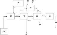
도 1은, 본 발명의 일 실시예에 따르는 CO2 분리 방법의 개략도를 제공하는 도면.
도 2는, 본 발명의 또 다른 실시예에 따르는 CO2 분리 시스템의 개략도를 제공하는 도면.
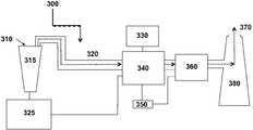
도 3은, 본 발명의 일 실시예에 따르는 CO2 분리 시스템과 합체된 발전소의 개략도를 제공하는 도면.
도 4는, 포틀란드 시멘트 공장의 개략도를 제공하는 도면.
도 5는, 본 발명의 일 실시예에 따르는 침전 플랜트와 동시 위치한 시멘트의 개략도를 제공하는 도면.
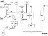
도 6은, 본 발명의 일 실시예에 따르는 채굴된 석회석 공급원료를 필요로 하지 않는 시멘트 공장의 개략도를 제공하는 도면.
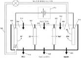
도 7a는, 양자를 용액으로부터 전기화학적으로 제거하기 위한 이전극 장치의 일 실시예의 도면을 제공하는 도면.
도 7b는, 양자를 용액으로부터 전기화학적으로 제거하기 위한 이전극 장치의 일 실시예의 도면을 제공하는 도면.
도 8은, 수산화물을 전기화학적으로 생성하기 위한 저전압 장치의 일 실시예의 도면을 제공하는 도면.
도 9는, 수산화물을 전기화학적으로 생성하기 위한 저전압 장치의 일 실시예의 도면을 제공하는 도면.
도 10은, 수산화물을 전기화학적으로 생성하기 위한 저전압 장치의 또 다른 실시예의 도면을 제공하는 도면.
도 11은, 본 발명의 일 실시예에 따르는 시스템의 개략도를 제공하는 도면.
도 12a, 12b 및 12c는, 본 발명의 일 실시예에 따르는 시스템의 개략도를 제공하는 도면.
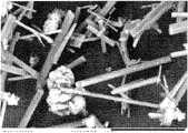
도 13a 및 13b는, 본 발명의 침전물의 사진을 제공하는 도면.
도 14는, 본 발명의 비정질 침전물의 사진을 제공하는 도면.
도 15는, 하기의 실험 부분에 보고된 CO2 흡수 실험의 도해 결과를 제공하는 도면.1 provides a schematic diagram of a method for separating CO2 in accordance with one embodiment of the present invention.
2 provides a schematic diagram of a CO2 separation system in accordance with another embodiment of the present invention.
3 provides a schematic diagram of a power plant incorporating a CO2 separation system in accordance with one embodiment of the present invention.
4 provides a schematic diagram of a Portland cement plant.
5 provides a schematic diagram of cement co-located with a precipitation plant according to one embodiment of the invention.
6 provides a schematic diagram of a cement plant that does not require mined limestone feedstock according to one embodiment of the present invention.
FIG. 7A provides a diagram of one embodiment of a two-electrode device for electrochemically removing both from a solution.
FIG. 7B provides a diagram of one embodiment of a two-electrode device for electrochemically removing both from a solution.
8 provides a diagram of one embodiment of a low voltage device for electrochemically generating hydroxides.
FIG. 9 provides a diagram of one embodiment of a low voltage device for electrochemically generating hydroxides.
FIG. 10 provides a diagram of another embodiment of a low voltage device for electrochemically generating hydroxides.
11 provides a schematic diagram of a system in accordance with an embodiment of the present invention.
12A, 12B and 12C provide a schematic diagram of a system in accordance with one embodiment of the present invention.
13A and 13B provide photographs of the precipitate of the present invention.
14 provides a photograph of an amorphous precipitate of the present invention.
FIG. 15 provides schematic results of the CO2 uptake experiments reported in the experimental section below.
관련 화학 반응Related Chemical Reactions
본 발명의 방법 및 시스템은 하기 화학 반응에 의해 요약되는 공정을 이용한다:The methods and systems of the present invention utilize a process that is summarized by the following chemical reactions:
(1) 액체, 기체 또는 고체상 형태의 탄소 함유 연료 공급원의 연소는 이산화탄소를 생성시킨다:(1) Combustion of a carbon containing fuel source in liquid, gas or solid form produces carbon dioxide:

(2) 이산화탄소의 공급원을 수원과 접촉시켜 이산화탄소를 용매화시켜서 이산화탄소의 수용액을 수득한다:(2) contacting the source of carbon dioxide with a water source to solvate the carbon dioxide to obtain an aqueous solution of carbon dioxide:

(3) 수중에 용해된 이산화탄소는 수성 탄산과의 평형을 달성한다:(3) Carbon dioxide dissolved in water achieves equilibrium with aqueous carbonic acid:

(4) 탄산은 2단계로 해리되는 약산이며, 여기에서 평형 균형은 용액의 pH에 의해 부분적으로 결정되며, 일반적으로 8-9 미만의 pH는 중탄산염 생성을 촉진하고 9-10을 초과하는 pH는 탄산염 생성을 촉진시킨다. 제 2 단계에서, 수산화물 공급원이 첨가되어 알칼리성을 증가시킬 수 있다:(4) Carbonic acid is a weak acid that dissociates in two stages, where the equilibrium balance is determined in part by the pH of the solution, in general pH below 8-9 promotes bicarbonate production and pH above 9-10 Promotes carbonate production In a second step, a hydroxide source can be added to increase alkalinity:

IIA족으로부터의 원소 금속 양이온과 탄산염 음이온의 반응은 금속 탄산염 침전물을 생성시킨다:Reaction of elemental metal cations with carbonate anions from Group IIA results in metal carbonate precipitates:

상기 반응식에서, X는 탄산염 기 또는 이의 복수와 화학적으로 결합할 수 있는 원소 또는 원소의 조합물이고, m 및 n은 화학양론적 양의 정수이다.In the above scheme, X is an element or combination of elements that can chemically bond with a carbonate group or a plurality thereof, and m and n are stoichiometric positive integers.
상세한 설명details
이산화탄소(CO2)를 분리하는 방법이 제공된다. 방법의 일면은 알칼리토금속 함유 물로부터 저장 안정성 이산화탄소 분리 생성물을 침전시킨 후, 예를 들어 생성물을 처리 장소에 위치시키거나 건축 재료와 같은 제조물의 부품으로서 생성물을 사용함으로써 생성물을 처리하는 것을 포함한다. 또한, 본 발명의 방법을 실시하기 위한 시스템이 제공된다.A method of separating carbon dioxide (CO2 ) is provided. One aspect of the process involves the precipitation of a storage stable carbon dioxide separation product from alkaline earth metal containing water and then processing the product by, for example, placing the product at a treatment site or using the product as part of a preparation, such as a building material. Also provided is a system for practicing the method of the present invention.
본 발명이 더 상세히 기술되기 전에, 본 발명은 물론 변할 수 있는 바와 같이 기술되는 특정 실시예로 제한되지 않는 것으로 이해되어야 한다. 또한, 본원에 사용되는 용어는 단지 특정 실시예를 기술하기 위한 것이며, 본 발명의 범위가 단지 첨부된 특허청구의 범위에 의해 제한될 것이므로 제한하려는 의도가 아님이 이해되어야 한다.Before the present invention is described in more detail, it is to be understood that the invention is not limited to the specific embodiments described as such may vary. It is also to be understood that the terminology used herein is for the purpose of describing particular embodiments only, and is not intended to be limiting, since the scope of the present invention will be limited only by the appended claims.
일정 범위의 값이 제공되는 경우, 상기 범위의 상한 및 하한과 상기 범위에서 임의의 다른 규정 값 또는 사이값의 사이에서, 문맥이 명백히 다른 식으로 규정하지 않는 한은 하한의 단위의 10배까지 각각의 사이값이 본 발명에 포함되는 것으로 이해되어야 한다. 이들 더 작은 범위의 상한 및 하한은 독립적으로 규정된 범위 내의 임의의 특정하게 배제된 한계에 따라 더 작은 범위에 포함되며, 또한 본 발명에 포함된다. 규정된 범위가 한계 중 하나 또는 둘 모두를 포함하는 경우, 포함된 한계 중 어느 하나 또는 둘 모두를 배제한 범위가 또한 본 발명에 포함된다.Where a range of values is provided, between the upper and lower limits of the range and any other prescribed or intervening value in the range, up to 10 times the unit of the lower limit, unless the context clearly dictates otherwise. It is to be understood that the intervalues are included in the present invention. The upper and lower limits of these smaller ranges are included in the smaller ranges according to any specifically excluded limits within the independently defined ranges and are also included in the present invention. Where the defined range includes one or both of the limits, the range excluding either or both of the included limits is also included in the present invention.
특정 범위는 본원에서 용어 "약"에 의해 전제되는 수치 값으로 제공된다. 용어 "약"은 본원에서, 이것이 전제하는 실제 수뿐만 아니라, 용어가 전제하는 수 근처이거나 대략적으로 그 수인 수에 대한 문자적 지지를 제공하기 위해 사용된다. 수가 특정하게 열거된 수 근처이거나 대략적으로 그 수 인지를 결정하는 데에 있어서, 근처 또는 대략적으로 열거되지 않은 수는 이것이 존재하는 문맥에서 특정하게 열거된 수의 실질적 등가물을 제공하는 수일 수 있다.Particular ranges are given herein as numerical values, predicated by the term "about". The term "about" is used herein to provide literal support for the actual number to which it presupposes, as well as the number that is near or approximately the number to which the term presupposes. In determining whether a number is near or approximately a specifically enumerated number, a number not near or approximately enumerated may be a number that provides a substantial equivalent of the specifically enumerated number in the context in which it exists.
다른 식으로 규정되지 않는 한은, 본원에 사용되는 모든 기술적 및 과학 용어는 본 발명이 속한 분야의 당업자에 의해 공통적으로 이해되는 바와 같은 의미를 갖는다. 본원에 기술되는 것과 유사하거나 동등한 임의의 방법 및 재료가 본 발명의 실시 및 시험에 또한 사용될 수도 있지만, 대표적인 예시적 방법 및 재료가 기술된다.Unless defined otherwise, all technical and scientific terms used herein have the same meaning as commonly understood by one of ordinary skill in the art to which this invention belongs. Although any methods and materials similar or equivalent to those described herein may also be used in the practice and testing of the present invention, representative exemplary methods and materials are described.
본 명세서에 인용되는 모든 공보 및 특허는, 각각의 개별적 공보 또는 특허가 본원에 참고문헌으로 인용되도록 특정하게 그리로 개별적으로 제시되는 것 처럼 참고문헌으로 인용되며, 어떠한 공보가 인용되는 지와 관련하여 방법 및/또는 재료를 기술하고 설명하도록 참고문헌으로 인용된다. 임의의 공보의 인용은 출원일 이전에 이의 발표를 위한 것이며, 본 발명이 종래의 발명에 비추어 이러한 공보에 앞서도록 부여되지 않는다는 입장으로서 구성되지 않아야 한다. 추가로, 제공되는 공고일은 독립적으로 확인하는 것이 필요할 수 있는 실제 공고일과 구별될 수 있다.All publications and patents cited herein are incorporated by reference as if each individual publication or patent were specifically and individually so incorporated by reference herein, and with regard to what publication is cited. It is incorporated by reference to describe and describe the method and / or material. The citation of any publication is for its publication prior to the filing date and should not be construed as an admission that the present invention is not construed to precede such publication in light of the prior invention. In addition, the announcement date provided may be distinguished from the actual announcement date that may need to be verified independently.
본원 및 첨부된 특허청구의 범위에 사용되는 바와 같이, 단수 형태는 문맥이 명백하게 다른 식으로 규정하지 않는 한은 복수를 포함함이 유의된다. 추가로, 특허청구의 범위는 임의의 선택적 요소를 배제하도록 초안될 수 있음이 유의된다. 이와 같이, 상기 규정은 특허청구의 범위 요소의 인용과 관련하여 "단독으로", "단지" 등과 같은 배타적 전문 용어의 사용 및 "음성적" 제한의 사용에 대한 선행 기준으로서 역할을 하도록 의도된다.As used in this specification and the appended claims, it is noted that the singular forms "a," "an," and "the" include plural unless the context clearly dictates otherwise. In addition, it is noted that the claims may be drafted to exclude any optional element. As such, the provision is intended to serve as a prerequisite for the use of exclusive terminology such as "alone", "only", and the like, and the use of "negative" limitations with respect to the citation of the scope element of the claims.
본 명세서를 읽을 때에 당업자들에게 명백해지는 바와 같이, 본원에 기술되고 예시되는 개별적 실시예는 각각 본 발명의 범위 또는 사상으로부터 벗어나지 않으면서 나머지 여러가지 실시예 중 어느 하나의 특징과 쉽게 분리되거나 조합될 수 있는 개별적 성분 및 특징을 갖는다. 임의의 열거된 방법은 열거된 경우의 순서로 또는 논리적으로 가능한 임의의 다른 순서로 수행될 수 있다.As will be apparent to those skilled in the art upon reading the specification, the individual embodiments described and illustrated herein can be readily separated or combined with the features of any one of the various embodiments without departing from the scope or spirit of the invention, respectively. Individual components and features. Any enumerated method may be performed in the order in which they are enumerated, or in any other order logically possible.
본 발명을 추가로 설명하는 데에 있어서, 본 발명의 실시예에 따르는 CO2 분리의 방법이 먼저 더 상세히 기술된다. 본 발명의 방법의 여러 실시예를 실시하는 데에 그 용도가 발견된 다른 시스템이 개요된다.In further describing the invention, the method of CO2 separation according to an embodiment of the invention is first described in more detail. Other systems in which their use has been found in practicing various embodiments of the method of the present invention are outlined.
COCO22 분리 방법 Separation method
상기 개요된 바와 같이, 본 발명은 CO2 분리 방법을 제공한다. "CO2 분리"는 CO2 중 일부 또는 전부가 이것이 제거되는 환경 중에 더 이상 존재하지 않도록, 산업 시설에 의해 생성되는 지구 대기 또는 기체 폐기물 스트림과 같은 환경으로부터 일정량의 CO2의 제거 또는 분리를 의미한다. 본 발명의 CO2 분리 방법은 CO2를 분리시켜서, 생성물을 생성하는 CO2가 생성물 중에서 분리될 정도로 일정량의 CO2로부터 저장 안정성 이산화탄소 분리 생성물을 생성시킨다. 저장 안정성 CO2 분리 생성물은 CO2가 대기 중의 기체로서 더 이상 존재하거나 이용되지 않도록 일정량의 CO2를 지상 저장 또는 수중 저장 안정성 형태와 같은 저장 안정성 형태 내로 혼입시킨 저장 안정성 조성물이다. 이와 같이, 본 발명의 방법에 따르는 CO2의 분리는 CO2 가스가 대기 내로 들어가는 것을 방지하고, CO2가 대기의 일부분이 되지 않는 방식으로 CO2의 장기간 저장을 허용한다.As outlined above, the present invention provides a method for separating CO2 . "CO2 Separation" means the removal or separation of a certain amount of CO2 from an environment, such as a global atmospheric or gaseous waste stream, produced by an industrial facility so that some or all of the CO2 is no longer present in the environment in which it is removed. do. The CO2 separation process of the present invention separates CO2 to produce a storage stable carbon dioxide separation product from an amount of CO2 such that the CO2 producing product is separated in the product. Storage stability The CO2 separation product is a storage stability composition incorporating an amount of CO2 into a storage stability form, such as above ground storage or underwater storage stability form, such that CO2 is no longer present or utilized as an atmospheric gas. In this way, the separation of CO2 according to the method of the present invention prevents the CO2 gas from entering the atmosphere, allowing long-term storage of CO2 in such a way that CO2 is not a part of the atmosphere.
본 발명의 방법의 실시예는 음성 탄소 풋프린트 방법이다. "음성 탄소 풋프린트"는 본 방법의 실시에 의해 분리되는(즉, 탄산염으로의 CO2의 전환을 통해) CO2의 중량이 방법을 실시하기 위해 생성되는(동력 생성, 염기 생성 등을 통해) CO2의 양보다 많음을 의미한다. 일부 경우에, 발명을 실시함으로써 분리되는 CO2의 중량은 방법을 실시하는 데에 생성되는 CO2의 중량을 10 내지 95%, 10 내지 90%, 10 내지 80%, 10 내지 70%, 10 내지 60%, 10 내지 50%,10 내지 40%, 10 내지 30%,10 내지 20%, 20 내지 95%, 20 내지 90%, 20 내지 80%, 20 내지 70%, 20 내지 60%, 20 내지 50%, 20 내지 40%, 20 내지 30%, 30 내지 95%, 30 내지 90%, 30 내지 80%, 30 내지 70%, 30 내지 60%, 30 내지 50%, 30 내지 40%, 40 내지 95%, 40 내지 90%, 40 내지 80%, 40 내지 70%, 40 내지 60%, 40 내지 50%, 50 내지 95%, 50 내지 90%, 50 내지 80%, 50 내지 70%, 50 내지 60% , 60 내지 95%, 60 내지 90%, 60 내지 80%, 60 내지 70%, 70 내지 95%, 70 내지 90%, 70 내지 80%, 80 내지 95%, 80 내지 90% 및 90 내지 95%를 포함하여 5 내지 100%와 같이 1 내지 100%까지 초과한다. 일부 경우에, 발명을 실시함으로써 분리되는 CO2의 중량은 방법을 실시하는 데에 생성되는 CO2의 중량을, 5% 이상, 10% 이상, 15% 이상, 20% 이상, 30% 이상, 40% 이상, 50% 이상, 60% 이상, 70% 이상, 80% 이상, 90% 이상, 95% 이상 초과한다.An embodiment of the method of the present invention is a negative carbon footprint method. "Negative carbon footprint" (via the power generation, and base generation, etc.) is generated to carry out the weight of the method (that is, through the conversion of CO2 to the carbonate) CO2 is separated by the practice of the method More than the amount of CO2 . In some cases, the weight of CO2 separated by carrying out the invention is 10 to 95%, 10 to 90%, 10 to 80%, 10 to 70%, 10 to 60 to the weight of CO2 produced in the process. %, 10-50%, 10-40%, 10-30%, 10-20%, 20-95%, 20-90%, 20-80%, 20-70%, 20-60%, 20-50 %, 20-40%, 20-30%, 30-95%, 30-90%, 30-80%, 30-70%, 30-60%, 30-50%, 30-40%, 40-95 %, 40 to 90%, 40 to 80%, 40 to 70%, 40 to 60%, 40 to 50%, 50 to 95%, 50 to 90%, 50 to 80%, 50 to 70%, 50 to 60 %, 60-95%, 60-90%, 60-80%, 60-70%, 70-95%, 70-90%, 70-80%, 80-95%, 80-90% and 90-95 Exceeding from 1 to 100%, such as from 5 to 100%, including%. In some cases, the weight of CO2 separated by the practice of the invention is greater than 5%, 10%, 15%, 20%, 30%, 40, 40 of the CO2 produced in the process. At least 50%, at least 50%, at least 60%, at least 70%, at least 80%, at least 90%, at least 95%.
상기 요약된 바와 같이, 본 발명의 방법은 이산화탄소가 "저장 안정성 형태"로 분리될 정도로 침전된 저장 안정성 이산화탄소 분리 생성물을 생성한다. "저장 안정성 형태"는 연장된 기간 동안, 예를 들어, 1년 이상, 5년 이상, 10년 이상, 25년 이상, 50년 이상, 100년 이상, 250년 이상, 1000년 이상, 10,000년 이상, 1,000,000년 이상, 100,000,000년 이상 또는 1,000,000,000년 이상 동안 있는 경우에도 현저한 분해 없이, 노출된 조건(예를 들어, 대기, 수중 환경 등에 대한 개방) 하에 예를 들어 지상 또는 수중에서 저장될 수 있는 물질의 형태를 의미한다. 저장 안정성 형태가 정상 빗물 pH 하에 지상에서 저장되면서 있는 경우에도 분해를 거의 일으키지 않음에 따라, 생성물로부터의 CO2 가스 방출에 대해 측정되는 바와 같이 있는 경우에도 분해의 양은 5%/년을 초과하지 않을 것이며, 특정 실시예에서 1%/년 또는 0.001%/년을 초과하지 않을 것이다. 지상 저장 안정성 형태는 다양한 상이한 환경 조건, 예를 들어 -100℃ 내지 600℃의 온도, 0% 내지 100%의 습도 하에서 저장 안정성이며, 여기에서 조건은 무풍, 바람 또는 폭풍일 수 있다. 일부 경우에, 저장 안정성 생성물은 건축 재료와 같은 제조물의 부품으로서, 예를 들어 시멘트 또는 콘크리트의 부품으로서 사용될 수 있다. 이들 실시예에서, 생성물은 저장시 안정한 CO2 분리 생성물이고, 이는 제조된 항목(건축재와 같은)에 생성물을 사용해도 생성물로부터 CO2가 방출되지 않기 때문이다. 특정 실시예에서, 포틀란드 시멘트와 조합되는 경우에 침전물의 탄산염 생성물 CO2를 방출시키지 않으면서 포틀란드 시메트의 화합물을 용해시키고 이와 조합한다.As summarized above, the process of the present invention produces a storage stable carbon dioxide separation product that is precipitated to such an extent that the carbon dioxide is separated into a "storage stable form". A "storage stability form" means an extended period of time, eg, at least 1 year, at least 5 years, at least 10 years, at least 25 years, at least 50 years, at least 100 years, at least 250 years, at least 1000 years, at least 10,000 years. Of substances that can be stored, for example, on the ground or in water, under exposed conditions (eg open to the atmosphere, aquatic environment, etc.) without significant degradation, even when they are present for more than 1,000,000 years, 100,000,000 years or more than 1,000,000,000 years. It means form. As storage stability forms rarely cause degradation even when stored above ground under normal rainwater pH, the amount of decomposition will not exceed 5% / year even if as is measured for CO2 gas emissions from the product. And in certain embodiments will not exceed 1% / year or 0.001% / year. The terrestrial storage stability form is storage stability under a variety of different environmental conditions, for example, temperatures of -100 ° C to 600 ° C, humidity of 0% to 100%, where the conditions can be windless, windy or stormy. In some cases, the storage stability product may be used as part of a preparation, such as building material, for example as part of cement or concrete. In these examples, the product is a CO2 separation product that is stable upon storage because using the product in the manufactured item (such as building material) does not release CO2 from the product. In certain embodiments, when combined with Portland cement, the compounds of Portland Simet are dissolved and combined without releasing the carbonate product CO2 of the precipitate.
본 발명의 방법에 의해 생성되는 저장 안정성 이산화탄소 분리 생성물 중에 존재하는 탄소의 양은 변할 수 있다. 일부 경우에, 생성물 중의 침전된 생성물 중에 존재하는 탄소의 양(동위원소 분석, 예를 들어13C 동위원소 분석과 같이 하기에 더 상세히 설명되는 프로토콜을 사용함으로서 결정되는 바와 같음)은 5 내지 15 부피%와 같이 1 내지 15 부피%이며, 5 내지 14 부피%, 5 내지 13 부피%, 6 내지 14 부피%, 6 내지 12 부피% 및 7 내지 12 부피%를 포함한다. 침전된 생성물을 생성하기 위해 생성되는 방법이 물을 CO2의 공급원과 접촉시키는 것을 포함하는 경우(예를 들어, 하기에 더 상세히 기술됨), 탄소의 실질적 양은 CO2의 공급원에서 발생하는 탄소일 수 있다(하기에 더 상세히 설명되는 프로토콜에 의해 결정됨). 실질적 양은 저장 안정성 이산화탄소 분리 생성물의 90 내지 100%를 포함하여 50 내지 100%와 같이 10 내지 100%가 이산화탄소 공급원(예를 들어 이산화탄소 함유 기체 스트림)으로부터 발생한다. 일부 경우에, 이산화탄소 공급원에 대해 추적할 수 있는 생성물 중에 존재하는 탄소의 양은 50% 이상, 60% 이상, 70% 이상, 80% 이상, 90% 이상, 95% 이상, 99% 이상이며, 100%를 포함한다.The amount of carbon present in the storage stable carbon dioxide separation product produced by the process of the invention can vary. In some cases, the amount of carbon present in the precipitated product in the product (as determined by using a protocol described in more detail below, such as isotope analysis, eg,13 C isotope analysis), is 5-15 volumes. 1 to 15% by volume, such as%, 5 to 14% by volume, 5 to 13% by volume, 6 to 14% by volume, 6 to 12% by volume and 7 to 12% by volume. If the method produced to produce the precipitated product includes contacting water with a source of CO2 (eg, described in more detail below), the substantial amount of carbon is carbonyl generated from the source of CO2 . (Determined by the protocol described in more detail below). Substantial amounts include 10-100%, such as 50-100%, including 90-100% of the storage stable carbon dioxide separation product from a carbon dioxide source (eg, a carbon dioxide containing gas stream). In some cases, the amount of carbon present in the traceable product for a carbon dioxide source is at least 50%, at least 60%, at least 70%, at least 80%, at least 90%, at least 95%, at least 99%, 100% It includes.
특정 실시예에서, CO2 분리 생성물은 CO2 분리 생성물, 예를 들어 생성되는 시멘트 또는 골재와 같은 건축 환경에 사용하려는 재료 매 1000 톤에 대해 150 톤 이상의 CO2을 포함하여, 약 100톤 이상의 CO2와 같이 약 50톤 이상의 CO2, 예를 들어 400톤 이상의 CO2를 포함하여, 약 350톤 이상의 CO2와 같이 약 300톤 이상의 CO2를 포함하여 약 250톤 이상의 CO2와 같이 약 200톤 이상의 CO2, 예를 들어 650톤 이상의 CO2를 포함하여, 약 600톤 이상의 CO2와 같이 약 550톤 이상의 CO2를 포함하여 약 500톤 이상의 CO2와 같이 450톤 이상의 CO2, 예를 들어 약 700톤 이상의 CO2를 저장할 수 있다. 이와 같이, CO2 분리 생성물은 약 25% 이상의 CO2를 포함하여 약 10% 이상의 CO2와 같이 약 5% 이상의 CO2, 예를 들어 약 90% 이상의 CO2를 포함하여 약 75% 이상의 CO2와 같이 약 50% 이상의 CO2를 포함한다.In certain embodiments, CO2 separated product is CO2 isolated product, e.g., including CO2 over 150 tons for the material sheets 1000 to use the built environment tone as generated cement or aggregate, at least about 100 tons of
본 발명의 방법에 의해 생성되는 저장 안정성 CO2 분리 생성물은 담수와 조합시에 초기 침전 생성물 조성물의 화합물보다 담수 중에 더 안정한 상이한 광물을 용해시키고 생성하는 탄산염 화합물을 포함할 수 있다. (초기 침전 생성물 조성물의 화합물이 담수와의 조합시에 상이한 성분들을 용해시키고 생성시킬 수 있지만, 임의의 이러한 반응에서 CO2 가스는 현저한 양으로 유리되지 않고, 일부 경우에는, 전혀 유리되지 않는다). 초기 침전 생성물 조성물의 화합물은 이들이 염수 준안정성 화합물로서 관찰될 있을 정도로 담수보다 염수에서 더욱 안정한 화합물일 수 있다. 전기량 적정으로 설명되는 프로토콜을 사용하여 전기량법에 의해 결정하여, 생성물 중의 탄산염의 양은 80% 이상을 포함하여 70% 이상과 같이 40% 이상이다.The storage stable CO2 separation product produced by the process of the invention may comprise carbonate compounds that dissolve and produce different minerals that are more stable in fresh water than the compounds of the initial precipitation product composition when combined with fresh water. (Although the compounds of the initial precipitation product composition may dissolve and produce different components in combination with fresh water, the CO2 gas is not liberated in significant amounts in some such reactions, and in some cases, not at all). The compounds of the initial precipitation product composition may be compounds that are more stable in saline than in fresh water such that they can be observed as saline metastable compounds. Determined by the calorimetry using the protocol described by the electrostatic titration, the amount of carbonate in the product is at least 40%, such as at least 70%, including at least 80%.
저장 안정성 침전 생성물은 비구별 비정질 탄산염 화합물을 포함하여, 2가지 이상의 상이한 탄산염 화합물, 예를 들어 3가지 이상의 상이한 탄산염 화합물, 5가지 이상의 상이한 탄산염 화합물 등과 같이 하나 이상의 상이한 탄산염 화합물을 포함할 수 있다. 본 발명의 침전 생성물의 탄산염 화합물은 분자식 Xm(CO3)n을 갖는 화합물일 수 있으며, 여기에서 X는 탄산염 기 또는 이의 복수와 화학적으로 결합할 수 있는 원소 또는 원소의 조합물이며, X는 특정 실시예에서 알칼리토금속(원소주기율표의 카럼 IIA에서 발견되는 원소)이고, 알칼리 금속(원소주기율표의 칼럼 IA에서 발견되는 원소)가 아니고, m 및 n은 화학양론적 양의 정수이다. 이들 탄산염 화합물은 Xm(CO3)n·H20이며, 분자식 중에 하나 이상의 구조적 물이 존재한다.The storage stability precipitation product may comprise one or more different carbonate compounds, including non-specific amorphous carbonate compounds, such as two or more different carbonate compounds, for example three or more different carbonate compounds, five or more different carbonate compounds, and the like. The carbonate compound of the precipitated product of the present invention may be a compound having the molecular formula Xm (CO3 )n , wherein X is an element or combination of elements capable of chemically bonding to a carbonate group or a plurality thereof, wherein X is In certain embodiments, m and n are stoichiometric positive integers, not alkaline earth metals (elements found in column IA of the Periodic Table of Elements) and alkali metals (elements found in column IA of the Periodic Table of Elements). These carbonate compounds are Xm (CO3 )n
탄산염 화합물은 비정질 또는 결정질일 수 있다. 특정 광물 분포, 즉 탄산염 화합물 조성물 중의 상이한 탄산염 광물의 상이한 유형 및 각각의 양의 동일성은 변할 수 있으며, 이를 유도하는 수원의 특정 성질 및 이를 유도하기 위해 사용되는 특정 조건에 의존할 것이다.The carbonate compound can be amorphous or crystalline. The specific mineral distribution, ie the identity of the different types and respective amounts of different carbonate minerals in the carbonate compound composition, may vary and will depend on the specific nature of the water source from which it is derived and the specific conditions used to derive it.
상기 제시된 바와 같이, 본 발명의 일부 실시예에서, 조성물 중의 탄산염 화합물은 임의의 pH의 담수와의 접촉시에 이들이 다른 담수 안정성 광물을 용해시키고 재침전할 정도로, 담수 중에서보다 염수 중에서 더 안정한 준안정성 탄산염 화합물이다.As set forth above, in some embodiments of the invention, the carbonate compounds in the composition are more stable in saline than in fresh water, such that upon contact with fresh water at any pH, they dissolve and reprecipitate other freshwater stable minerals. Compound.
특정 실시예에서, 탄산염 화합물은 예를 들어 주사 전자 현미경에 의해 결정하여, 0.1 미크론 내지 100 미크론, 예를 들어 1 내지 100 미크론, 또는 10 내지 100 미크론, 또는 50 내지 100 미크론, 일부 실시예에서는, 0.5 내지 10 미크론의 입자 크기를 갖는 작은 입자로서 존재한다. 일부 실시예에서, 입자 크기는 이정점 또는 다정점 분포를 나타낸다. 특정 실시예에서, 입자 크기는 예를 들어 바우너, 에미트 앤드 텔러(BET) 표면적 분석(Brauner, Emmit, & Teller(BET) Surface Area Analysis)에 의해 결정하여 0.5 내지 2.0 ㎡/gm과 같이, 0.5 내지 100 ㎡/gm, 0.5 내지 50 ㎡/gm의 고표면적을 갖는다. 일부 실시예에서, 본 발명의 방법에 의해 생성되는 CO2 분리 생성물은 로드형 결정 및 비정질 고체를 포함할 수 있다. 로드형 결정은 구조상 변할 수 있으며, 특정 실시예에서 10 대 1과 같이 500 대 1의 길이 대 직경비를 갖는다. 특정 실시예에서, 결정의 길이는 5 ㎛ 내지 100 ㎛와 같이 0.5 ㎛ 내지 500 ㎛이다. 또 다른 실시예에서, 실질적으로 완전히 비정질인 고체가 생성된다.In certain embodiments, the carbonate compound is determined by scanning electron microscopy, for example, from 0.1 micron to 100 microns, such as from 1 to 100 microns, or from 10 to 100 microns, or from 50 to 100 microns, in some embodiments, It is present as small particles with a particle size of 0.5 to 10 microns. In some examples, the particle size exhibits a peak or multi-peak distribution. In certain embodiments, the particle size is determined by, for example, a Waurner, Emmit, & Teller (BET) Surface Area Analysis, such as 0.5 to 2.0 m 2 / gm, It has a high surface area of 0.5-100 m 2 / gm and 0.5-50 m 2 / gm. In some examples, the CO2 separation product produced by the process of the present invention may comprise rod-shaped crystals and amorphous solids. Rod-shaped crystals can vary in structure, and in certain embodiments have a length to diameter ratio of 500 to 1, such as 10 to 1. In certain examples, the length of the crystal is 0.5 μm to 500 μm, such as 5 μm to 100 μm. In yet another embodiment, a solid that is substantially completely amorphous is produced.
침전 생성물의 탄산염 화합물은 칼슘, 마그네슘, 나트륨, 칼륨, 황, 붕소, 규소, 스트론튬 및 이들의 조합물과 같은 많은 상이한 양이온을 포함할 수 있지만, 이에 제한되지는 않는다. 칼슘 및 마그네슘 탄산염 화합물과 같은 이가 금속 양이온의 탄산염 화합물이 중요하다. 관심있는 특정 탄산염 화합물은 탄산칼슘 광물, 마그네슘 탄산염 광물, 칼슘 마그네슘 탄산염 광물을 포함하지만 이에 제한되지는 않는다. 관심있는 탄산칼슘 광물은 칼사이트(CaCO3), 아라고나이트(CaCO3), 바테라이트(CaCO3), 이카이트(CaCO3·6H2O) 및 비정질 탄산칼슘(CaCO3·nH2O)를 포함하지만 이에 제한되지는 않는다. 관심있는 마그네슘 탄산염 광물은 마그네사이트(MgCO3), 배링토나이트(MgCO3·2H2O), 네스퀘호나이트(MgCO3·3H2O), 랜포다이트(MgCO3·5H2O), 히드로마그네사이트, 비정질 마그네슘 탄산칼슘(MgCO3·nH2O)을 포함하지만 이에 제한되지는 않는다. 관심있는 칼슘 마그네슘 탄산염 광물은 돌로마이트(CaMgCO3), 훈타이트(CaMg(CO3)4) 및 세르게에바이트(Ca2Mg11(CO3)13·H2O)를 포함하지만 이에 제한되지는 않는다. 생성물의 탄소 화합물은 수화의 하나 이상의 물을 포함하거나, 무수물일 수 있다.The carbonate compound of the precipitation product may include, but is not limited to, many different cations such as calcium, magnesium, sodium, potassium, sulfur, boron, silicon, strontium and combinations thereof. Of particular interest are carbonate compounds of divalent metal cations such as calcium and magnesium carbonate compounds. Particular carbonate compounds of interest include, but are not limited to, calcium carbonate minerals, magnesium carbonate minerals, calcium magnesium carbonate minerals. Calcium carbonate minerals of interest include Calsite (CaCO3 ), Aragonite (CaCO3 ), Vaterite (CaCO3 ), Icite (CaCO3 · 6H2 O) and Amorphous calcium carbonate (CaCO3 · nH2 O). Including but not limited to. Magnesium carbonate minerals of interest are magnesite (MgCO3 ), baringtonite (MgCO3 · 2H2 O), nesquefonite (MgCO3 · 3H2 O), lanpoid (MgCO3 · 5H2 O), hydromagnesite And amorphous magnesium calcium carbonate (MgCO3 nH2 O). Interested calcium magnesium carbonate minerals include dolomite (CaMgCO3), Hoon tight (CaMg (CO3)4) and a byte(Ca 2 Mg 11 (CO 3 ) 13 · H 2 O) to sereuge but are not limited to . The carbon compound of the product may comprise one or more waters of hydration, or may be anhydride.
일부 경우에, 침전물 중의 마그네슘 탄산염 화합물의 중량은 침전물 중의 탄산칼슘 화합물의 중량을 초과한다. 예를 들어, 침전물 중의 마그네슘 탄산염 화합물의 중량은 침전물 중의 탄산칼슘 화합물의 중량을 10% 이상, 15% 이상, 20% 이상, 25% 이상, 30% 이상과 같이 5% 이상으로 초과할 수 있으며, 일부 경우에, 침전물 중의 마그네슘 탄산염 화합물 대 탄산칼슘 화합물의 중량비는 2-3 대 1을 포함하여 2-4 대 1과 같이 1.5-5 내지 1이다.In some cases, the weight of the magnesium carbonate compound in the precipitate exceeds the weight of the calcium carbonate compound in the precipitate. For example, the weight of the magnesium carbonate compound in the precipitate may exceed the weight of the calcium carbonate compound in the precipitate by at least 5%, such as at least 10%, at least 15%, at least 20%, at least 25%, at least 30%, In some cases, the weight ratio of magnesium carbonate compound to calcium carbonate compound in the precipitate is 1.5-5 to 1, such as 2-4 to 1, including 2-3 to 1.
일부 경우에, 침전 생성물은 이가 금속 이온 수산화물과 같은 수산화물, 예를 들어, 칼슘 및/또는 마그네슘 수산화물을 포함할 수 있다. 관심있는 주요 칼슘 수산화물 광물은 포틀란다이트 Ca(OH)2 및 이의 비정질 수화 유사체이다. 관심있는 주요 마그네슘 수산화물 광물은 브루사이트 Mg(OH)2 및 이의 비정질 수화 유사체이다.In some cases, the precipitation product may include hydroxides such as divalent metal ion hydroxides, such as calcium and / or magnesium hydroxides. The main calcium hydroxide minerals of interest are portlandite Ca (OH)2 and amorphous hydration analogs thereof. The main magnesium hydroxide minerals of interest are brucite Mg (OH)2 and amorphous hydration analogs thereof.
침전 생성물이 알칼리토금속 이온 함유 수원으로부터 유도됨에 따라, 이들은 이들을 침전시키는 수원 중에 존재하고 수원으로부터 유래하는 조성물을 확인하는 하나 이상의 성분을 포함할 것이며, 이들 확인 성분 및 이의 양은 본원에서 집합적으로 수원 확인제로서 언급된다. 예를 들어, 수원이 해수인 경우, 탄산염 화합물 조성물 중에 존재할 수 있는 확인 화합물은 염화물, 나트륨, 황, 칼륨, 브롬화물, 규소, 스트론튬 등을 포함하지만 이에 제한되지는 않는다. 이러한 공급원 확인 또는 "마아커" 원소는 일반적으로 소량, 예를 들어, 2,000 ppm 이하와 같이 20,000 ppm 이하의 양으로 존재한다. 특정 실시예에서, "마아커" 화합물은 아라고나이트 격자 내로 혼입되는 침전물 중에 존재할 수 있는 스트론튬이며, 10,000 ppm 이하, 특정 실시예에서 5 내지 1000 ppm을 포함하여 5 내지 5000 ppm, 예를 들어 5 내지 100 ppm을 포함하여 5 내지 500 ppm과 같이 3 내지 10,000 ppm을 이룰 수 있다. 관심있는 또 다른 "마아커" 화합물은 탄산염 화합물 중의 칼슘에 대해 20 몰% 치환 이하의 양으로 존재할 수 있는 마그네슘이다. 조성물의 수원 확인제는 물 유도 탄산염 조성물을 생성하기 위해 사용되는 특정 수원, 예를 들어 해수에 의존하여 변할 수 있다. 특정 실시예에서, 침전물의 탄산칼슘 함량은 40% w/w 이상과 같이 25% w/w 이상이며, 50% w/w 이상, 예를 들어 60% w/w이다. 탄산염 화합물 조성물은 특정 실시예에서 이를 침전시키는 수원에 의해 영향 받고 따라서 이를 반영하는 칼슘/마그네슘 비를 갖는다. 특정 실시예에서, 칼슘/마그네슘 몰비는 5/1 내지 1/3 Ca/Mg와 같이 10/1 내지 1/5 Ca/Mg이다. 특정 실시예에서, 탄산염 조성물은 수원 확인 탄산염 대 수산화물 비를 가짐을 특징으로 하며, 특정 실시예에서, 이는 10 대 1과 같이 100 대 1이며, 1 대 1을 포함한다.As the precipitation products are derived from alkaline earth metal ion containing water sources, they will include one or more components that are present in the water source from which they are precipitated and which identify the composition derived from the water source, and these identifying components and amounts thereof are collectively referred to herein as source identification agents. It is referred to as. For example, where the water source is seawater, the identifying compounds that may be present in the carbonate compound composition include, but are not limited to, chloride, sodium, sulfur, potassium, bromide, silicon, strontium, and the like. Such source identification or "marker" elements are generally present in small amounts, for example up to 20,000 ppm, such as up to 2,000 ppm. In certain embodiments, the "marker" compound is strontium, which may be present in the precipitate incorporated into the aragonite lattice, from 5 to 5000 ppm, including from 5 to 1000 ppm, including from 5 to 1000 ppm in certain embodiments It can comprise 3 to 10,000 ppm, including 100 ppm, such as 5 to 500 ppm. Another “marker” compound of interest is magnesium, which may be present in an amount of up to 20 mole percent substitutions relative to calcium in the carbonate compound. The source identifier of the composition may vary depending on the particular water source used to produce the water derived carbonate composition, for example seawater. In certain embodiments, the calcium carbonate content of the precipitate is at least 25% w / w, such as at least 40% w / w, and at least 50% w / w, for example 60% w / w. Carbonate compound compositions have a calcium / magnesium ratio that is affected by and thus reflects the water source in which it precipitates in certain embodiments. In certain embodiments, the calcium / magnesium molar ratio is 10/1 to 1/5 Ca / Mg, such as 5/1 to 1/3 Ca / Mg. In certain embodiments, the carbonate composition is characterized by having a source identification carbonate to hydroxide ratio, and in certain embodiments, it is 100 to 1, such as 10 to 1, and includes 1 to 1.
본 발명의 방법에서, 알칼리토금속 함유 물은 탄산염 화합물 침전 조건으로 처리되어 침전된 저장 안정성 이산화탄소 분리 생성물을 생성시킨다. 알칼리토금속 함유 물은 수행하려는 특정 분리 방법에 의존하여 변할 수 있다. 관심있는 물 중 하나의 유형은 해수이다. 용어 "해수"는 담수와는 상이한 많은 상이한 유형의 수성 유체를 언급하기 위해 사용되며, 용어 "해수"는 반담수, 해수 및 염수(토양의 표면에서 물의 본류에서 발견되는 표면 염수 및 토양 아래에서 발견되는 심부 염수와 같은 언연 염수뿐만 아니라, 지열 플랜트 폐수, 탈염 폐수 등과 같은 인공 염수를 포함함), 뿐만 아니라 담수의 염도보다 높은 염도를 갖는 다른 식염수를 포함한다. 용어 "염수"는 염으로 포화되거나 거의 포화된 물을 언급하며, 50 ppt(1000부당 부) 이상의 염도를 갖는다. 반담수는 담수보다 더 짠 물이지만, 0.5 내지 35 ppt의 염도를 갖는 해수만큼 짜지 않다. 해수는 바다 또는 대양으로부터의 물이며, 35 내지 50 ppt의 염도를 갖는다. 본 발명의 시멘트의 탄산염 광물 조성물을 유도하는 해수원은 바다, 대양, 호수, 늪, 하구, 석호, 심부 염수, 알칼리성 호수, 연해 등과 같은 천연 공급원, 또는 인공 공급원일 수 있다.In the process of the invention, the alkaline earth metal containing water is subjected to carbonate compound precipitation conditions to produce precipitated storage stable carbon dioxide separation products. The alkaline earth metals content may vary depending on the particular separation method to be performed. One type of water of interest is seawater. The term “sea water” is used to refer to many different types of aqueous fluids that differ from fresh water, and the term “sea water” is found below semi-fresh water, sea water and brine (surface brine and soil found in the mainstream of water at the surface of the soil). Artificial salts such as geothermal plant wastewater, demineralized wastewater, and the like), as well as other saline with salinity higher than that of fresh water. The term "brine" refers to water saturated or nearly saturated with salts and having a salinity of at least 50 ppt (1000 parts per part). Half freshwater is saltier than fresh water, but not as salty as seawater with a salinity of 0.5 to 35 ppt. Sea water is water from the sea or ocean and has a salinity of 35 to 50 ppt. The seawater source inducing the carbonate mineral composition of the cement of the present invention may be a natural source, such as an ocean, ocean, lake, swamp, estuary, lagoon, deep brine, alkaline lake, inshore, or artificial source.
본 발명의 방법에 사용될 수 있는 또 다른 유형의 물은 담수이다. 광물이 비교적 없는 공급원 내지 광물이 풍부한 공급원을 포함하는 임의의 적합한 담수 원이 사용될 수 있다. 관심있는 담수 원은 광물 담수원이다. 관심있는 광물 담수원은 경수 또는 호수 또는 연해, 예를 들어 양자의 제거 및/또는 pH 이동을 위한 알칼리성의 공급원 및/또는 CO2에 의해 침전되게 되는 광물의 공급원을 제공할 수 있는 알칼리성 호수 또는 연해(예를 들어, 터키의 레이크 반(Lake Van))과 같이 천연일 수 있으며, 이러한 호수는 본원 어디에서나 추가로 설명된다. 관심있는 광물 풍부 담수 원은 또한 예를 들어, 연수로부터 광물 풍부 물을 생성시킴으로써 인공 제조될 수 있다. 예를 들어, 광물 부족(연성) 물은 칼슘 및/또는 마그네슘 이온 공급원과 같은 바람직한 이온의 공급원과 접촉하여, 본 발명의 방법을 사용하기 위해 적합한 광물 풍부 물을 생성시킬 수 있다.Another type of water that can be used in the process of the invention is fresh water. Any suitable freshwater source can be used, including those that are relatively free of minerals and those that are rich in minerals. Of interest are freshwater sources. Mineral freshwater sources of interest are hard water or lakes or waters, for example alkaline lakes or waters which can provide a source of minerals to be precipitated by CO2 and / or an alkaline source for removal and / or pH shifting of both. (Eg Lake Van, Turkey), which may be natural and such lakes are further described elsewhere herein. Mineral rich freshwater sources of interest can also be artificially produced, for example, by producing mineral rich water from soft water. For example, mineral deficient (soft) water may be contacted with a preferred source of ions, such as calcium and / or magnesium ion sources, to produce mineral rich water suitable for use with the methods of the present invention.
상기 제시된 바와 같이, 본 발명의 방법에 사용되는 알칼리토금속 함유 물은 천연 공급원으로부터 얻어지는 물일 수 있다. 대안적으로, 물은 초기 물로부터, 예를 들어 하나 이상의 광물을 물에 첨가함으로써 제조되는 물일 수 있다. 이와 같이, 일부 방법은 마그네슘, 칼슘 등과 같은 하나 이상의 이가 금속 이온의 공급원을 초기 물에 첨가함으로써 초기 물로부터 알칼리토금속 함유 물을 제조하는 것을 포함한다. 마그네슘 이온의 공급원은 마그네슘 수산화물, 마그네슘 산화물 등을 포함하지만 이에 제한되지는 않는다. 칼슘 이온의 공급원은 칼슘 수산화물, 칼슘 산화물 등을 포함하지만 이에 제한되지는 않는다. 이러한 이온의 천연 및 인공 공급원이 둘 모두 사용될 수 있다. 이러한 이온의 특정 천연 공급원은 감람석, 사문석, 페리오도타이트, 탈크 등과 같은 유색 광물을 포함하지만 이에 제한되지는 않는다. 침전 전에 수원, 예를 들어 해수에 대한 보충 마그네슘(Mg) 이온의 첨가는 침전물의 수율을 증가시킬 뿐만 아니라, 침전물의 조성에 영향을 주어서, 비제한적으로 감람석, 사문석 및 Mg(OH)2(브루사이트)와 같은 광물을 사용함으로써 CO2 분리를 증가시키기 위한 수단을 제공한다. 특정 Mg 이온 공급원은 천연 또는 인공 공급원일 수 있으며, Mg 광물에 대해 순수하거나, 불순하며, 예를 들어 관심있는 Mg 광물 및 다른 광물 및 성분으로 이루어진 조성물일 수 있다.As set forth above, the alkaline earth metal containing water used in the process of the present invention may be water obtained from a natural source. Alternatively, the water may be water prepared from the initial water, for example by adding one or more minerals to the water. As such, some methods include producing alkaline earth metal-containing water from initial water by adding one or more sources of divalent metal ions to the initial water, such as magnesium, calcium, and the like. Sources of magnesium ions include, but are not limited to, magnesium hydroxide, magnesium oxide, and the like. Sources of calcium ions include, but are not limited to, calcium hydroxide, calcium oxide, and the like. Both natural and artificial sources of these ions can be used. Specific natural sources of these ions include, but are not limited to, colored minerals such as olivine, serpentine, periodite, talc and the like. The addition of supplemental magnesium (Mg) ions to a water source, such as seawater, prior to precipitation, not only increases the yield of the sediment, but also affects the composition of the sediment, resulting in, but not limited to, olivine, serpentine and Mg (OH)2 (bru The use of minerals to provide a means for increasing CO2 separation. The particular Mg ion source may be a natural or artificial source and may be pure or impure to Mg minerals, for example a composition consisting of Mg minerals of interest and other minerals and components.
본 발명의 일부 방법에서, 물(예를 들어, 염수 또는 광물 풍부 물)은 물을 침전 조건으로 처리하기 전에 CO2의 공급원과 접촉하지 않는다. 이들 방법에서, 물은 예를 들어 방법의 실시 전에 물이 노출되는 환경으로부터 얻어진 중탄산염 이온의 형태로 이와 결합되는 CO2의 양을 가질 것이다. 물을 본 발명의 침전 조건으로 처리하면, 상기 CO2가 저장 안정성 침전물로 전환되고, 따라서 CO2가 분리된다. 본 발명의 방법으로 처리된 물이 다시 대기와 같은 천연 환경에 노출되면, 대기로부터의 더 많은 CO2가 물에 의해 흡수되어, 대기로부터 CO2가 완전히 제거되고, 상응하는 양의 CO2가 저장 안정성 생성물 내로 혼입되게 되며, 여기에서 광물 풍부 수원은 예를 들어 하기에 더 상세히 설명되는 바와 같이 CO2의 공급원과 접촉할 수 있다. 이들 방법의 실시예는 지구의 대기로부터 직접 CO2 가스를 분리하는 방법으로서 관찰될 수 있다. 방법의 실시예는 지구의 대기로부터 CO2의 제거를 위해 효율적이다. 예를 들어, 방법의 실시예는 염수 1 갈론당 0.1 M 이상을 포함하여, 0.05 M 이상과 같이 0.025 M 이상의 속도로 CO2를 제거하도록 구성된다.In some methods of the invention, water (eg, brine or mineral rich water) is not in contact with the source of CO2 prior to treating the water with precipitation conditions. In these methods, the water will have an amount of CO2 bound thereto, for example in the form of bicarbonate ions obtained from the environment to which the water is exposed prior to the implementation of the method. Treatment of water with the precipitation conditions of the present invention converts the CO2 into a storage stable precipitate, thus separating the CO2 . When the water treated by the method of the present invention is again exposed to a natural environment such as the atmosphere, more CO2 from the atmosphere is absorbed by the water, so that CO2 is completely removed from the atmosphere, and a corresponding amount of CO2 is stored. It will be incorporated into the stable product, where the mineral rich water source can be contacted with a source of CO2 , for example as described in more detail below. Embodiments of these methods can be observed as a method of separating CO2 gas directly from the Earth's atmosphere. Embodiments of the method are efficient for the removal of CO2 from the earth's atmosphere. For example, an embodiment of the method is configured to remove CO2 at a rate of at least 0.025 M, such as at least 0.05 M, including at least 0.1 M per gallon of brine.
산업용 폐기 가스가 CO2의 비교적 농축된 공급원일 지라도, 본 발명의 방법 및 시스템이 또한 예를 들어 연도 가스보다 훨씬 낮은 농도의 CO2를 함유하는 덜 농축된 공급원, 예를 들어 대기 공기로부터 CO2를 제거하기 응용될 수 있음이 당업자에 의해 인지될 것이다. 이와 같이, 일부 실시예에서, 본 발명의 방법 및 시스템은 본원에서 기술된 공정을 사용하여 안정한 침전물을 생성시킴으로써 대기 중의 CO2의 농도를 감소시키는 것을 포함한다. 이들 경우에, 대기 공기 중의 CO2의 농도는 10% 이상, 20% 이상, 30% 이상, 40% 이상, 50% 이상, 60% 이상, 70% 이상, 80% 이상, 90% 이상, 95% 이상, 99% 이상, 99.9% 이상 또는 99.99%까지 감소될 수 있다. 대기 CO2의 이러한 감소는 본원에 기술된 바와 같은 수율로, 또는 더 낮은 수율로 달성될 수 있으며, 하나의 침전 단계로 또는 일련의 침전 단계로 달성될 수 있다.Industrial waste gases have even a relatively concentrated source of CO2, the method of the invention and a less concentrated supply of the system is also, for example containing CO2 in a much lower concentration than the flue gas, such as CO2 from the atmosphere air It will be appreciated by those skilled in the art that the present invention may be applied to remove the? As such, in some embodiments, the methods and systems of the present invention include reducing the concentration of CO2 in the atmosphere by producing stable precipitates using the processes described herein. In these cases, the concentration of CO2 in atmospheric air is at least 10%, at least 20%, at least 30%, at least 40%, at least 50%, at least 60%, at least 70%, at least 80%, at least 90%, 95%. Above 99%, above 99.9% or below 99.99%. This reduction of atmospheric CO2 can be achieved in yields as described herein, or in lower yields, in one precipitation step or in a series of precipitation steps.
일부 실시예에서, CO2의 공급원은 물이 본 발명의 침전 조건으로 처리되기 전, 도중 또는 심지어는 후와 같이 방법을 수행하는 동안의 일부 시점에서 알칼리토금속 이온 함유 물과 접촉한다. 이들 실시예에서 알칼리토금속 함유 물과 접촉하는 CO2의 공급원은 임의의 편리한 CO2 공급원일 수 있다. CO2 공급원은 액체, 고체(예를 들어, 드라이아이스), 초임계 유체 또는 가스상 CO2 공급원일 수 있다.In some embodiments, the source of CO2 is contacted with alkaline earth metal ion-containing water at some point during the process, such as before, during or even after the water has been treated with the precipitation conditions of the present invention. In these examples, the source of CO2 in contact with the alkaline earth metal containing water may be any convenient CO2 source. The CO2 source can be a liquid, solid (eg dry ice), supercritical fluid or gaseous CO2 source.
특정 실시예에서, CO2 공급원은 가스상 CO2 공급원이다. 이러한 가스상 CO2 공급원은 특정 경우에 산업 시설로부터의 폐기 공급물이다. 산업 시설의 특성은 이들 실시예에서 변할 수 있으며, 여기에서 관심있는 산업 시설은 동력장치, 정련기, 시멘트 공장, 강 플랜트, 및 연료 연소 또는 다른 공정 단계(예를 들어, 시멘트 공장에 의한 하소)의 부생성물로서 CO2를 생성하는 산업 시설을 포함한다. 폐기 공급물은 산업 시설의 활성 공정의 부생성물로서 생성되는 기체의 스트림(또는 유사 스트림)을 의미한다. 기체 스트림은 실질적으로 순수한 CO2, 또는 CO2 및 하나 이상의 부가적 가스를 포함하는 다성분 기체 스트림일 수 있다. 본 방법의 실시예에서 CO2 공급원으로서 사용될 수 있는 다성분 기체 스트림(CO2 함유)는 환원 가스, 예를 들어 합성가스, 이동 가스, 천연 가스 및 수소 등 및 산화 상태 스트림, 예를 들어 연소로부터의 연도 가스를 포함한다. 본 발명에 따라 처리될 수 있는 관심있는 특정 다성분 기체 스트림은 산소 함유 연소 산업 시설 연도 가스, 터보 충전 보일러 생성물 가스, 석탄 기화 생성물 가스, 이동 석탄 기화 생성물 가스, 호기성 분해 생성물 가스, 수원 천연 가스 스트림, 재생된 천연 가스 또는 메탄 수화물 등을 포함한다.In certain embodiments, the CO2 source is a gaseous CO2 source. Such gaseous CO2 sources are in some cases waste feeds from industrial facilities. The characteristics of the industrial plant may vary in these embodiments, where the industrial plant of interest is power plant, refinery, cement plant, steel plant, and fuel combustion or other process steps (eg, calcination by cement plant). Industrial facilities that produce CO2 as a by-product of By waste feed is meant a stream (or similar stream) of gas produced as a byproduct of the active process of an industrial facility. The gas stream may be a substantially pure CO2 , or a multicomponent gas stream comprising CO2 and one or more additional gases. Multi-component gas streams (containing CO2 ) that can be used as CO2 sources in embodiments of the process include reducing gases such as syngas, mobile gas, natural gas and hydrogen, etc., and oxidation state streams, such as from combustion. Contains flue gas. Certain multicomponent gas streams of interest that may be treated in accordance with the present invention are oxygen-containing combustion industrial plant flue gases, turbo charged boiler product gases, coal vaporization product gases, mobile coal vaporization product gases, aerobic decomposition product gases, water source natural gas streams. Recycled natural gas or methane hydrate.
다양한 상이한 가스상 폐기물 스트림이 본 발명의 방법에 따라 처리되어 CO2를 분리시킬 수 있다. 관심있는 가스상 폐기물 스트림은 특정 실시예에서 200,000 ppm 내지 2000 ppm, 예를 들어 130,000 ppm 내지 2000 ppm을 포함하여, 200,000 ppm 내지 1000 ppm과 같이 200 ppm 내지 1,000,000 ppm의 양으로 존재하는 CO2를 갖는다.Various different gaseous waste streams can be treated according to the process of the present invention to separate the CO2 . The gaseous waste stream of interest has, in certain embodiments, CO2 present in an amount of 200 ppm to 1,000,000 ppm, such as 200,000 ppm to 1000 ppm, including 200,000 ppm to 2000 ppm, for example 130,000 ppm to 2000 ppm.
폐기물 스트림은 하나 이상의 부가적 성분, 예를 들어 물, NOx(질소 산화물; NO 및 NO2), SOx(황 산화물; SO, SO2 및 SO3), VOC(휘발성 유기 화합물), 수은 및 미립자(미립 물질, 가스 중에 현탁된 고체 또는 액체의 입자)를 포함할 수 있다.The waste stream may contain one or more additional components such as water, NOx (nitrogen oxides; NO and NO2 ), SOx (sulfur oxides; SO, SO2 and SO3 ), VOCs (volatile organic compounds), mercury and particulates ( Particulate matter, particles of a solid or liquid suspended in a gas).
폐기물 스트림은 다양한 상이한 유형의 산업 시설로부터 생성될 수 있다. 특정 실시예에서는, 화석 연료, 예를 들어, 석탄, 오일, 천연 가스, 및 비제한적으로 타르 모래, 중유, 오일 셰일 등과 같은 천연 유기 연료 석출물의 인공 연료 생성물을 연소시키는 산업 시설에 의해 생성되는 폐기물 스트림이 중요하다. 특정 실시예에서, 발전소는 미분탄 발전소, 초임계 석탄 발전소, 질량 연소 석탄 발전소, 유동층 석탄 발전소, 가스 또는 오일 발화 보일러 및 스트림 터빈 발전소, 가스 또는 오일 발화 보일러 단순 사이클 가스 터빈 발전소 및 가스 또는 오일 발화 보일러 복합 사이클 가스 터빈 발전소이다. 특정 실시예에서, 합성 가스, 즉 유기 물질, 예를 들어 석탄, 바이오매스 등의 기화에 의해 생성되는 가스를 연소시키는 발전소에 의해 생성되는 페기물 스트림이 관심 있으며, 특정 실시예에서는, 이러한 플랜트는 통합 기화 복합 사이클(IGCC) 플랜트이다. 특정 실시예에서는, 열회수 증기 발생기(Heat Recovery Steam Generator (HRSG)) 시설에 의해 생성된 폐기물 스트림이 중요하다.Waste streams can be generated from various different types of industrial facilities. In certain embodiments, waste generated by an industrial facility that burns fossil fuels, eg, artificial fuel products of coal, oil, natural gas, and natural organic fuel precipitates such as, but not limited to tar sand, heavy oil, oil shale, and the like. The stream is important. In certain embodiments, the power plant is a pulverized coal power plant, a supercritical coal power plant, a mass combustion coal power plant, a fluidized bed coal power plant, a gas or oil fired boiler and a stream turbine power plant, a gas or oil fired boiler, a simple cycle gas turbine power plant and a gas or oil fired boiler. Combined cycle gas turbine power plant. In certain embodiments, there is a waste stream generated by a power plant that combusts synthesis gas, ie, gases produced by vaporization of organic materials, such as coal, biomass, and the like, and in certain embodiments, such plants are integrated. Vaporized combined cycle (IGCC) plant. In certain embodiments, waste streams generated by a Heat Recovery Steam Generator (HRSG) facility are important.
본 발명의 일부 실시예에서, 발전소로부터의 연도 가스 중에 함유된 CO2의 실질적으로 100%가 안정한 광물로서 분리되며; 이는 단일 침전 단계 또는 다중 침전 단계로 수행될 수 있고, 추가로, 예를 들어 연도 가스 중에서 CO2의 농도가 감소됨에 따라 CO2를 분리하기 위한 다른 방법을 수반할 수 있으며, 가스 중의 원래의 CO2를 모두 제거하기 위한 에너지 소모에서 금지되는 더욱 에너지 집약적 공정이 가스 중의 최종 CO2를 제거하는 데에 실시되게 될 수 있게 된다. 이와 같이, 일부 실시예에서, 발전소에 들어가는 가스(보통 대기 공기)는 본 발명의 방법 및 시스템에 의해 처리된 플랜트로부터 배출되는 연도 가스 중의 CO2의 농도보다 높은 농도의 CO2를 함유할 수 있다. 따라서, 일부 실시예에서, 본 발명의 방법 및 시스템은 CO2를 포함하는 가스, 예를 들어 대기 공기를 발전소에 공급하는 단계; 예를 들어 화석 연료의 연소에 의해 발전소 중의 가스를 처리하여 O2를 연소시키고 CO2를 생성시킨 후, 배출 가스를 처리하여 CO2를 제거하는 단계; 및 발전소로부터 가스를 방출시키는 단계로서, 발전소로부터 방출되는 가스가 발전소에 공급되는 가스보다 낮은 CO2 함량을 갖는 단계를 포함하는 방법을 포함한다. 일부 실시예에서, 발전소로부터 방출되는 가스는 발전소에 들어가는 가스보다 최소한 10% 더 적은 CO2, 또는 최소한 20% 더 적은 CO2, 또는 최소한 30% 더 적은 CO2, 또는 최소한 40% 더 적은 CO2, 또는 최소한 50% 더 적은 CO2, 또는 최소한 60% 더 적은 CO2, 또는 최소한 70% 더 적은 CO2, 또는 최소한 80% 더 적은 CO2, 또는 최소한 90% 더 적은 CO2, 또는 최소한 95% 더 적은 CO2, 또는 최소한 99% 더 적은 CO2, 또는 최소한 99.5% 더 적은 CO2, 또는 최소한 99.9% 더 적은 CO2를 함유하며; 일부 실시예에서는, 발전소에 들어가는 가스는 대기 공기이고, 발전소로부터 배출되는 가스는 처리된 연도 가스이다.In some embodiments of the invention, substantially 100% of the CO2 contained in the flue gas from the power plant is separated as a stable mineral; This may be carried out in a single precipitation stage or in multiple precipitation stages and may additionally involve other methods for separating the CO2 as the concentration of CO2 in the flue gas is reduced, for example. the more energy-intensive process that is prohibited in the energy consumption it is possible to be presented embodiment in removing the final CO2 in the gas to remove any2. As such, in some embodiments, the gas entering the power plant (usually atmospheric air) may contain a concentration of CO2 that is higher than the concentration of CO2 in the flue gas exiting the plant treated by the methods and systems of the present invention. . Thus, in some embodiments, the methods and systems of the present invention include the steps of supplying a gas comprising CO2 , such as atmospheric air, to a power plant; For example, the method comprising by the combustion of fossil fuel burning the O2 gas to the processing of the plant and then generate CO2, by treating the exhaust gas to remove the CO2; And releasing gas from the power plant, wherein the gas discharged from the power plant has a lower CO2 content than the gas supplied to the power plant. In some embodiments, the gas emitted from the power plant is at least 10% less CO2 , or at least 20% less CO2 , or at least 30% less CO2 , or at least 40% less CO2 than the gas entering the power plant. , Or at least 50% less CO2 , or at least 60% less CO2 , or at least 70% less CO2 , or at least 80% less CO2 , or at least 90% less CO2 , or at least 95% Contains less CO2 , or at least 99% less CO2 , or at least 99.5% less CO2 , or at least 99.9% less CO2 ; In some embodiments, the gas entering the power plant is atmospheric air and the gas exiting the power plant is treated flue gas.
관심있는 폐기물 스트림은 또한 시멘트 공장에 의해 생성되는 폐기물 스트림을 포함한다. 본 발명의 방법에 폐기물 스트림이 사용될 수 있는 시멘트 공장은 습식 공정 및 건식 공정 둘 모두를 포함하며, 이 플랜트는 선가마 또는 회전 가마를 사용할 수 있고 사전 하소기를 포함할 수 있다. 이들 유형의 산업 시설은 각각 단일 연료를 발화시킬 수 있거나, 2가지 이상의 연료를 순차적으로 또는 동시에 발화시킬 수 있다.Waste streams of interest also include waste streams produced by cement plants. Cement plants in which waste streams can be used in the process of the present invention include both wet and dry processes, which can use pre kilns or rotary kilns and may include precalciners. Each type of industrial facility may ignite a single fuel, or may ignite two or more fuels sequentially or simultaneously.
중요한 폐기물 스트림은 산업 시설 배출 가스, 예를 들어 연도 가스이다. "연도 가스"는 산업 시설의 연료로서 또한 공지된 연통으로 향하는 화석 또는 바이오매스 연료로부터의 연소 생성물로부터 얻어지는 가스를 의미한다. 연료의 발화에 의해 생성되는 CO2 이외에, CO2는 또한 다른 공업 공정(예를 들어, 시멘트 공장 중의 광물의 하소)의 결과로서 방출될 수 있다. 연도 가스의 조성은 변할 수 있다. 특정 실시예에서, 연도 가스 중의 CO2의 양은 2000 ppm 내지 200,000 ppm과 같이 350 ppm 내지 400,000 ppm이며, 2000 ppm 내지 180,000 ppm을 포함할 수 있다. 다른 성분, 예를 들어 물, NOx, SOx, VOC, 수은 및 미립자가 또한 연도 가스 중에 존재할 수 있다. 연도 가스의 온도는 예를 들어 6O℃ 내지 7000℃와 같이 0℃ 내지 2000℃일 수 있으며, 100℃ 내지 400℃를 포함한다.An important waste stream is industrial plant emissions, for example flue gas. "Flue gas" means a gas that is obtained from combustion products from fossil or biomass fuels that are directed to known communication as fuel of an industrial installation. In addition to CO2 produced by ignition of the fuel, CO2 may also be released as a result of other industrial processes (eg, calcination of minerals in cement plants). The composition of the flue gas can vary. In certain embodiments, the amount of CO2 in the flue gas is 350 ppm to 400,000 ppm, such as 2000 ppm to 200,000 ppm, and may include 2000 ppm to 180,000 ppm. Other components can also be present in the flue gas, such as water, NOx, SOx, VOC, mercury and particulates. The temperature of the flue gas may be from 0 ° C. to 2000 ° C., for example, from 60 ° C. to 7000 ° C., and includes 100 ° C. to 400 ° C.
본 발명의 방법에 사용되는 가스상 폐기물 스트림은 가스상 폐기물 스트림을 산업 시설로부터 침전 플랜트로 수송하는 임의의 편리한 방식으로 산업 시설로부터 침전 자리로 제공될 수 있다. 특정 실시예에서, 폐기물 스트림에는, 가스 컨베이어, 예를 들어, 산업 시설의 자리로부터 예를 들어 산업 시설의 연료를 침전 자리의 하나 이상의 위치로 운반하는 도관이 제공된다. 가스상 폐기물 스트림의 공급원은 침전 위치로부터 100 마일 이상을 포함하여, 10 마일 이상과 같이 1 마일 이상인 위치일 정도로, 침전 자리에 비해 먼 위치일 수 있다. 예를 들어, 가스상 폐기물 스트림은 원격 산업 시설로부터 CO2 가스 수송 시스템, 예를 들어 파이프라인을 통해 침전 자리로 운반된다. 산업 시설 생성 CO2 함유가스는 이것이 침전 자리(증, 탄산염 화합물 침전 플랜트)에 도달하기 전에, 예를 들어 다른 성분을 제거하는 등의 처리를 하거나 하지 않을 수 있다. 또 다른 경우에, 가스상 폐기물 스트림의 공급원은 침전 자리에 가까우며, 이러한 경우는 침전 자리가 탄산염 화합물 침전 반응기를 통합시킨 발전소와 같은 가스상 폐기물 스트림의 공급원과 통합된다.The gaseous waste stream used in the process of the present invention may be provided from the industrial facility to the settling site in any convenient way to transport the gaseous waste stream from the industrial facility to the precipitation plant. In certain embodiments, the waste stream is provided with a conduit that carries a gas conveyor, for example fuel from an industrial facility, to, for example, fuel from an industrial facility to one or more locations of the settling site. The source of the gaseous waste stream may be remote from the settling site, such as at least one mile, such as at least 10 miles, including at least 100 miles from the settling site. For example, a gaseous waste stream is conveyed from a remote industrial facility to a settling site via a CO2 gas transport system, such as a pipeline. The industrial plant generated CO2 containing gas may or may not be treated before it reaches the sedimentation site (vapor, carbonate compound precipitation plant), for example by removing other components. In another case, the source of the gaseous waste stream is close to the settling site, in which case the settling site is integrated with the source of the gaseous waste stream, such as a power plant incorporating a carbonate compound precipitation reactor.
바람직한 경우, 산업 시설로부터의 전체 가스상 폐기물 스트림의 일부분이 침전 반응에 사용될 수 있다. 이들 실시예에서, 침전에 사용되는 가스상 폐기물 스트림의 일부분은 60% 이하와 같이 75% 이하일 수 있으며, 50% 이하를 포함한다. 또 다른 실시예에서, 산업 시설에 의해 생성되는 가스상 폐기물 스트림의 실질적으로 전부, 예를 들어 산업 시설에 의해 생성되는 연도 가스의 실질적으로 전부가 침전에 사용된다. 이들 실시예에서, 공급원에 의해 생성되는 가스상 폐기물 스트림(예를 들어, 연도 가스)의 95% 이상을 포함하여 90% 이상과 같이 80% 이상, 100% 이하가 침전 동안 사용될 수 있다.If desired, a portion of the entire gaseous waste stream from an industrial facility may be used for the precipitation reaction. In these embodiments, the portion of the gaseous waste stream used for precipitation may be up to 75%, such as up to 60%, and includes up to 50%. In yet another embodiment, substantially all of the gaseous waste stream produced by the industrial facility, for example substantially all of the flue gas produced by the industrial facility, is used for precipitation. In these embodiments, at least 80% and at most 100% may be used during the precipitation, such as at least 90%, including at least 95% of the gaseous waste stream (eg, flue gas) produced by the source.
상기 제시된 바와 같이, 가스상 폐기물 스트림은 산업 시설의 연도 또는 유사한 구조로부터 얻어진다. 이들 실시예에서, 라인, 예를 들어 도관이 연도에 연결되어, 가스가 라인을 통해 연도를 빠져나가고, 침전 시스템(하기에 더 상세히 기술됨)의 적절한 위치(들)로 수송된다. 가스상 폐기물 스트림이 사용되는 침전 시스템의 일부의 특정 구성에 의존하여, 가스상 폐기물 스트림이 얻어지는 공급원의 위치는 변하여, 예를 들어 적절하거나 바람직한 온도를 갖는 폐기물 스트림을 제공할 수 있다. 이와 같이, 60℃ 내지 700℃와 같이 0℃ 내지 1800℃의 온도를 갖는 가스상 폐기물 스트림이 바람직한 특정 실시예에서, 연도 가스는 보일러 또는 가스 터빈, 가마의 배출 지점에서, 또는 바람직한 온도를 제공하는 발전소 또는 연통을 통한 이의의 지점에서 얻어질 수 있다. 바람직한 경우, 연도 가스는 응축 및 관련된 문제를 피하기 위해, 예를 들어 125℃의 이슬점을 초과하는 온도로 유지된다. 이것이 가능하지 않은 경우, 예를 들어 도관이 빠르게 열화되지 않도록 플루오로카본(예를 들어, 폴리(테트라플루오로에틸렌))으로 안을 대고, 물로 희석되고 pH 조절된 스테인리스강인 도관을 사용하여 응축의 악영향을 감소시키기 위한 단계가 취해질 수 있다.As set forth above, the gaseous waste stream is obtained from the year or similar structure of the industrial facility. In these embodiments, a line, for example a conduit, is connected to the flue so that gas exits the flue through the line and is transported to the appropriate location (s) of the precipitation system (described in more detail below). Depending on the particular configuration of the portion of the sedimentation system in which the gaseous waste stream is used, the location of the source from which the gaseous waste stream is obtained may vary, for example, to provide a waste stream having an appropriate or desired temperature. As such, in certain embodiments where a gaseous waste stream having a temperature of 0 ° C. to 1800 ° C., such as 60 ° C. to 700 ° C. is desired, the flue gas is at a discharge point of a boiler or gas turbine, kiln, or at a power plant that provides the desired temperature. Or at the point of objection through communication. If desired, the flue gas is maintained at a temperature above the dew point of 125 ° C., for example, to avoid condensation and related problems. If this is not possible, the adverse effects of condensation are used, for example, by using conduits which are stainless steel diluted with water and pH-regulated, rinsed with fluorocarbons (e.g. poly (tetrafluoroethylene)) to prevent degradation of the conduit quickly. Steps may be taken to reduce this.
효율성을 제공하기 위해, 기체 폐기물 스트림을 생성하는 산업 시설은 침전 시스템과 동시 위치될 수 있다. "동시 위치"는 산업 시설와 침전 시스템 사이의 거리가 30 내지 350 야드를 포함하여, 25 내지 400 야드와 같이 10 내지 500 야드이다. 바람직한 경우, 침전 및 산업 시설은 예를 들어 침전 플랜트가 산업 시설의 40 야드 내에 있는 경우에, 서로에 대해, 도관 비용을 최소화시킬 뿐만 아니라, 온도 손실을 최소화하고 응축을 방지하도록 구성될 수 있다.To provide efficiency, industrial facilities that produce gaseous waste streams can be co-located with the precipitation system. "Simultaneous location" is 10 to 500 yards, such as 25 to 400 yards, including 30 to 350 yards between the industrial facility and the precipitation system. If desired, the precipitation and industrial facilities can be configured to minimize conduit costs, as well as minimize temperature losses and prevent condensation, with respect to each other, for example when the precipitation plant is within 40 yards of the industrial facility.
특정 실시예에서, 산업용 기능(예를 들어, 동력 발생, 시멘트 생성 등) 및 본 발명의 침전 시스템을 포함하는 완전 통합 플랜트가 또한 관심이 있다. 이러한 통합 플랜트에서, 하기에 기술되는 바와 같은 통상적인 산업 시설 및 침전 시스템은 바람직한 통합 플랜트를 제공하도록 변형된다. 변형은 연통의 조정, 펌핑, 제어부, 계기화, 모니터링, 플랜트 에너지 사용, 예를 들어 침전 부품, 예를 들어 기계적 프레스, 펌프, 컴프레서의 일부를 가동시키기 위한 스팀 터빈 에너지의 사용, 공기로부터 열교환기로의 증기 또는 열로부터 얻어지는 시멘트 및/또는 발전소로부터의 열의 사용 등을 포함하지만 이에 제한되지는 않는다.In certain embodiments, also fully integrated are plants of interest comprising industrial functions (eg power generation, cement generation, etc.) and precipitation systems of the present invention. In such integrated plants, conventional industrial facilities and precipitation systems as described below are modified to provide the desired integrated plant. Variations can include coordination, pumping, control, instrumentation, monitoring, use of plant energy, for example the use of steam turbine energy to run sedimentary parts such as mechanical presses, pumps, compressors, from air to heat exchangers. The use of heat from cement and / or power plants derived from steam or heat, and the like.
CO2 공급원과 접촉하는 물의 pH는 변할 수 있다. 일부 경우에, CO2 공급원과 접촉하는 물의 pH는 pH가 6.5 이하, 6 이하, 5.5 이하, 5 이하, 4.5 이하 또는 4 이하와 같이 7 미만일 정도로 산성이다. 또 다른 실시예에서, 물의 pH는 중성 내지 약간 염기성이며, 이는 물의 pH가 7.5 내지 8.5를 포함하여 7 내지 8.5와 같이 7 내지 9임의 의미한다.The pH of the water in contact with the CO2 source can vary. In some cases, the pH of the water in contact with the CO2 source is acidic such that the pH is less than 7, such as at most 6.5, at most 6, at most 5.5, at most 5, at most 4.5, or at most 4. In another embodiment, the pH of the water is neutral to slightly basic, meaning that the pH of the water is 7 to 9, such as 7 to 8.5, including 7.5 to 8.5.
일부 경우에, 알칼리토금속 이온 함유 물(알칼리성 용액 또는 중성 식염 알칼리성 물 포함)과 같은 물은 이산화탄소 함유 가스상 스트림과 같은 CO2 공급원과 접촉할 경우 염기성이다. 이들 경우에, 염기성이면서, 물의 pH는 저장 안정성 이산화탄소 분리 생성물의 첨전을 유발하기에는 불충분하다. 이와 같이, pH는 9 이하를 포함하여, 9.3 이하와 같이 9.5 이하일 수 있다.In some cases, water such as alkaline earth metal ion containing water (including alkaline solutions or neutral saline alkaline water) is basic when contacted with a CO2 source such as a carbon dioxide containing gaseous stream. In these cases, while being basic, the pH of the water is insufficient to cause electrification of the storage stable carbon dioxide separation product. As such, the pH may be 9.5 or less, including 9.3 or less, such as 9.3 or less.
어떤 경우, 상술된 바와 같은 pH는 이산화탄소 함유 가스상 스트림과 접촉하는 동안 실질적으로 일정한 값으로 유지되거나, pH는 특정 pH에서 출발하고 CO가 계속 도입됨에 따라 pH를 점차적으로 증가시킴에 의해서와 같이 염기 소모 또는 양자를 제거하는 다른 수단을 최소화시키면서 CO2 흡수를 최대화하도록 조절될 수 있다. pH가 실질적으로 일정하게 유지되는 실시예에서, "실질적으로 일정한"은 이산화탄소 공급원과의 일부 접촉 단계 동안 pH의 변화 정도는 0.10 이하와 같이 0.25 이하를 포함하여 0.50 이하와 같이 0.75 이하임을 의미한다. pH는 실질적으로 일정한 값으로 유지되거나, CO2 흡수를 최대화시키지만 임의의 편리한 접근법을 사용하여 침전 없이 수산화물 침전을 방지하도록 조절될 수 있다. 일부 경우에, pH는 실질적으로 일정한 값으로 유지되거나, 실질적으로 일정한 pH를 제공하는 방식으로 물에 충분한 양의 염기를 첨가함으로써 물의 CO2 충전 동안 침전 없이 CO2 흡수를 최대화시키도록 조절된다. 수산화마그네슘과 같은 산화물 및 수산화물을 포함하지만 이에 제한되지는 않는 임의의 편리한 염기 또는 염기의 조합물이 첨가되며, 여기에서 적합한 염기의 추가의 예는 하기에 기술된다. 또 다른 경우에, pH는 실질적으로 일정한 값으로 유지되거나, 하기에 기술되는 프로토콜과 같은 전기화학적 프로토콜의 사용을 통해 CO2 흡수를 최대화시키도록 조절되어, 물의 pH가 실질적으로 일정한 값으로 전기화학적으로 유지되게 된다. 놀랍게도, 예 IV에 나타낸 바와 같이, 예를 들어 염기의 첨가에 의한 해수의 단순한 분산(양자의 제거)를 통해 약 20% CO2를 포함하는 가스 중에 함유된 CO2를 50% 넘게 흡수하는 것이 가능한 것으로 밝혀졌다.In some cases, the pH as described above is maintained at a substantially constant value during contact with the carbon dioxide containing gaseous stream, or the pH is depleted in base consumption, such as by starting at a particular pH and gradually increasing the pH as CO is continuously introduced. Or can be adjusted to maximize CO2 absorption while minimizing other means of removing protons. In embodiments where the pH is maintained substantially constant, "substantially constant" means that the degree of change in pH during some contacting steps with the carbon dioxide source is 0.75 or less, such as 0.50 or less, including 0.25 or less, such as 0.10 or less. The pH can be maintained at a substantially constant value or can be adjusted to maximize CO2 uptake but prevent hydroxide precipitation without precipitation using any convenient approach. In some cases, the pH is maintained at a substantially constant value, or adjusted to maximize CO2 uptake without precipitation during CO2 filling of water by adding a sufficient amount of base to the water in a manner that provides a substantially constant pH. Any convenient base or combination of bases is added, including but not limited to oxides such as magnesium hydroxide and hydroxides, where further examples of suitable bases are described below. In another case, the pH is maintained at a substantially constant value or adjusted to maximize CO2 uptake through the use of an electrochemical protocol such as the protocol described below, such that the pH of the water is electrochemically maintained at a substantially constant value. Will be maintained. Surprisingly, as shown in Example IV, it is possible to absorb more than 50% of the CO2 contained in a gas containing about 20% CO2 , for example by simple dispersion of the seawater (removal of protons) by addition of a base, for example. It turned out.
일부 실시예에서, 본 발명의 방법 및 시스템은 CO2의 산업용 공급원과 같은 CO2의 가스상 공급원, 예를 들어 발전소로부터의 연도 가스 또는 시멘트 공장로부터의 폐가스 중의 CO2의 5% 이상, 10% 이상, 15% 이상, 20% 이상, 25% 이상 30% 이상, 35% 이상, 40% 이상, 45% 이상, 50% 이상, 55% 이상, 60% 이상, 65% 이상, 70% 이상, 75% 이상, 80% 이상, 85% 이상, 90% 이상, 95% 이상 또는 99% 이상을 흡수할 수 있다. 일부 실시예에서, 본 발명의 방법 및 시스템은 CO2의 산업용 공급원과 같은 CO2의 가스상 공급원, 예를 들어 발전소로부터의 연도 가스 또는 시멘트 공장로부터의 폐가스 중의 50% 이상을 흡수할 수 있다.In some embodiments, the present method and system, a gaseous source of CO2, such as industrial source of CO2, for example, from a power plant flue gas or cement plants by more than 5% of CO2 in the waste gas from, more than 10% , 15% or more, 20% or more, 25% or more 30% or more, 35% or more, 40% or more, 45% or more, 50% or more, 55% or more, 60% or more, 65% or more, 70% or more, 75% At least 80%, at least 85%, at least 90%, at least 95%, or at least 99%. In some embodiments, the method and system of the present invention may absorb more than 50% of the waste gases from the flue gas from the power plant or a cement plant, for the gas phase source, for example, of CO2, such as industrial source of CO2.
예를 들어, 상술된 바와 같이 CO2에 의해 초기 물을 충전하는 것 이외에, 방법의 일부 실시예는 마그네슘 이온 공급원을 3 이상, 예를 들어, 5 이상과 같은 4 이상, 예를 들어 7 이상을 포함하여 6 이상의 물 중의 마그네슘 대 칼슘 비를 생성하기에 충분한 방식으로 초기 물에 첨가하는 것을 포함한다. 특정 실시예에서, 원하는 마그네슘 대 칼슘 이온비는 3 내지 10, 예를 들어, 4 내지 8이다. 임의의 편리한 마그네슘 이온 공급원이 물에 첨가되어 바람직한 마그네슘 대 칼슘 이온비를 제공할 수 있으며, 여기에서 관심있는 특정 마그네슘 이온 공급원은 Mg(OH)2, 사문석, 감람석, 유색 광물 및 초유색 광물을 포함하지만 이에 제한되지는 않는다. 물에 첨가되는 마그네슘 이온 공급원의 양은 예를 들어 특정 마그네슘 이온 공급원 및 초기 물에 의존하여 변할 수 있으며, 이로부터 CO2 충전 물이 생성된다. 특정 실시예에서, 물에 첨가되는 마그네슘 이온의 양은 5 내지 100 g/ℓ 물을 포함하여 1 내지 100 g/ℓ 물과 같이 0.01 내지 100.0 g/ℓ, 예를 들어 5 내지 50 g/ℓ 물을 포함하여 5 내지 80 g/ℓ 물이다. 특정 실시예에서, 물에 첨가되는 마그네슘 이온의 양은 제조업자의 지시에 따라 메트로옴 적정기(Metrohm Titrator)(스위스의 메트로옴 아게(Metrohm AG))에서 결정하여, 약 0.1 g/ℓ 이상을 포함하여 약 0.08 g/ℓ 이상과 같이 약 0.06 g/ℓ 이상의 경도 판독으로 물을 생성하기에 충분하다. 마그네슘 이온 공급원은 임의의 편리한 프로토콜, 예를 들어 교반, 혼합 등을 사용하여 물과 조합될 수 있다.For example, in addition to filling the initial water with CO2 as described above, some embodiments of the method may utilize a magnesium ion source of at least 3, such as at least 4, such as at least 7, And adding to the initial water in a manner sufficient to produce a magnesium to calcium ratio in the water of at least six, including. In certain embodiments, the desired magnesium to calcium ion ratio is 3 to 10, for example 4 to 8. Any convenient source of magnesium ions can be added to the water to provide the desired magnesium to calcium ion ratio, where the particular source of magnesium ions of interest includes Mg (OH)2 , serpentine, olivine, colored minerals and super-coloured minerals. But it is not limited to this. The amount of magnesium ion source added to the water may vary depending, for example, on the particular magnesium ion source and initial water, from which a CO2 charge is produced. In certain embodiments, the amount of magnesium ions added to the water is 0.01 to 100.0 g / l, such as 5 to 50 g / l, such as 1 to 100 g / l, including 5 to 100 g / l. Including 5 to 80 g / l water. In certain embodiments, the amount of magnesium ions added to the water is determined in a Metrohm Titrator (Metrohm AG, Switzerland) according to the manufacturer's instructions, including about 0.1 g / l or more. A hardness reading of at least about 0.06 g / l, such as at least 0.08 g / l, is sufficient to produce water. The magnesium ion source can be combined with water using any convenient protocol, such as stirring, mixing, and the like.
마그네슘, 칼슘 또는 마그네슘과 칼슘의 조합물의 공급원을 물에 첨가하는 실시예에서, 공급원은 고체 형태, 예를 들어 크고, 경질이며, 종종 용액 내로 겔화되기가 어려운 입자 또는 입자의 응집물의 형태로 존재할 수 있다. 예를 들어, 브루사이트로서의 Mg(OH)2는 사문석, 감람석, 및 다른 규산마그네슘 광물, 및 시멘트 폐기물 등과 같은, 본 발명의 실시예에 유용한 많은 광물과 같은 형태로 존재할 수 있다. 임의의 적합한 방법이 이러한 공급원으로부터 마그네슘과 같은 이가 양이온을 탄산염과 반응하여 이가 양이온의 탄산염을 생성하기에 적합한 형태로 수용액 내로 도입시키기 위해 사용될 수 있다. 입자 크기를 감소시킴으로써 표면적으로 증가시키는 것은 볼 분쇄 및 제트 밀링과 같은 당분야에 널리 공지된 수단에 의해 수행될 수 있는 하나의 이러한 방법이다. 제트 밀링은 용해도를 증강시키는, 성분의 결정 구조의 대부분을 파괴하는 추가의 장점을 갖는다. 또한, 강한 음파 파쇄가 사용되어 반응 속도를 바람직한 값, 예를 들어 106X 이상으로 증가시키는 음파 화학이 중요하다. 크기가 감소되거나 감소되지 않은 입자는 HCI, H2SO4 등과 같은 산에 대한 노출과 같이 수용액을 조장하는 조건에 노출될 수 있으며; 일부 실시예에서는 약산 또는 염기가 또는한 사용될 수 있다 [참조예: 본원에 전체 내용이 참고문헌으로 인용된 미국 특허 공고 번호 2005/0022847; 2004/0213705; 2005/0018910; 2008/0031801; 및 유럽 특허 EP1379469 및 EP1554031; 및 PCT 공고 번호 WO 07/016271 및 WO 08/061305].In embodiments in which a source of magnesium, calcium or a combination of magnesium and calcium is added to the water, the source may be present in solid form, for example in the form of large or hard particles, or aggregates of particles which are often difficult to gel into solution. have. For example, Mg (OH)2 as brucite may be present in the form of many minerals useful in embodiments of the present invention, such as serpentine, olivine, and other magnesium silicate minerals, and cement waste. Any suitable method may be used to introduce divalent cations, such as magnesium, from such sources into the aqueous solution in a form suitable for reacting with carbonates to produce carbonates of divalent cations. Increasing the surface area by reducing the particle size is one such method that can be performed by means well known in the art, such as ball milling and jet milling. Jet milling has the additional advantage of breaking most of the crystalline structure of the component, which enhances solubility. Also important is sonic chemistry where strong sonic shredding is used to increase the reaction rate to a desired value, for example 106 X or more. Particles that have been reduced or not reduced in size may be exposed to conditions that promote aqueous solutions, such as exposure to acids such as HCI, H 2S O4 , and the like; In some embodiments, weak acids or bases may be used or referenced. See, eg, US Patent Publication No. 2005/0022847, which is incorporated by reference in its entirety; 2004/0213705; 2005/0018910; 2008/0031801; And European Patents EP1379469 and EP1554031; And PCT Publication Nos. WO 07/016271 and WO 08/061305.
일부 실시예에서, 본 발명의 방법 및 시스템은 광물 공급원으로서 사문석을 이용한다. 사문석은 천연적으로 생성되고 일반적으로 화학식 X2-3Si2O2(OH)4에 의해 기술되는 풍부한 광물이며, 여기에서 X는 Mg, Ca, Fe2+, Fe3+, Ni, Al, Zn 및 Mn으로부터 선택되며, 사문석 재료는 주로 마그네슘 수산화물 및 실리카로 구성되는 불균질 혼합물이다. 본 발명의 일부 실시예에서, 사문석은 마그네슘의 공급원으로서 뿐만 아니라, 수산화물의 공급원으로서 사용된다. 이와 같이, 본 발명의 일부 실시예에서, 수산화물은 사문석을 용해시킴으로써 물로부터의 양자의 제거 및/또는 pH의 조절을 위해 제공되며; 이들 실시예에서, 산 용해는 용해를 촉진하기 위해 이상적이지 않고, 제트 밀링 및/또는 음파 파쇄와 같은 다른 수단이 사용된다. 회분식 또는 연속 공정에서, 사문석 또는 다른 광물을 용해시키기 위한 시간은, 공정이 바람직한 규모로 출발하고 용해의 적절한 수준에 대해 충분한 시간이 경과되면, 용해된 재료의 연소 스트림이 무기한으로 유지되므로, 임계적이지 않다. 이와 같이, 바람직한 수준으로의 용해가 수일, 수주, 수개월 또는 심지어는 수년이 걸릴 지라도, 공정이 바람직한 용해가 일어난 제 1 시점에 도달하면, 이는 무기한으로 유지될 수 있다. 바람직한 용해가 일어난 시점 이전에, 공정에 마그네슘 및/또는 수산화물의 일부 또는 전부를 제공하기 위해 다른 공정이 사용될 수 있다. 사문석은 또한 철 성분이 종종 바람직한 경우에 예를 들어 시멘트에 대해 사용되는 침전물의 유용한 성분인 철의 공급원이다.In some embodiments, the methods and systems of the present invention utilize serpentine as a mineral source. Serpentine is produced naturally generally a mineral rich described by the formulaX 2 -3 Si 2 O 2 ( OH) 4, where X isMg, Ca, Fe 2 +, Fe 3 +, Ni, Al, Selected from Zn and Mn, the serpentine material is a heterogeneous mixture consisting mainly of magnesium hydroxide and silica. In some embodiments of the invention, the serpentine is used as a source of hydroxide as well as a source of magnesium. As such, in some embodiments of the invention, hydroxides are provided for the removal of protons from water and / or for the adjustment of pH by dissolving serpentine; In these examples, acid dissolution is not ideal to promote dissolution, and other means such as jet milling and / or sonic fracturing are used. In a batch or continuous process, the time for dissolving serpentine or other minerals is critical because the combustion stream of dissolved material remains indefinitely once the process has started to the desired scale and sufficient time has passed for an appropriate level of dissolution. Not. As such, even if dissolution to the desired level takes days, weeks, months, or even years, once the process reaches the first point at which the desired dissolution occurs, it can remain indefinitely. Prior to the point where the desired dissolution occurs, other processes may be used to provide some or all of the magnesium and / or hydroxides to the process. Serpentine is also a source of iron, which is a useful component of the sediment used for cement, for example when the iron component is often desired.
본 발명에 유용한 규산염계 광물의 다른 예는 감람석, 일반적으로 또한 화학식 X2(SiO4)n에 의해 기술될 수 있는 천연 마그네슘-철 규산염((Mg, Fe)2SiO4)(여기에서, X는 Mg, Ca, Fe2+, Fe3+, Ni, Al, Zn 및 Mn으로부터 선택되고, n=2 또는 3임); 및 규회석과 같은 칼슘 규산염을 포함하지만 이에 제한되지는 않는다. 광물은 개별적으로 또는 서로 조합하여 사용될 수 있다. 부가적으로, 광물은 천연적으로 발견될 수 있거나, 제조될 수 있다. 산업용 부생성물의 예는 폐기 시멘트 및 칼슘 풍부 플라이 재를 포함하지만 이에 제한되지는 않는다.Another example of a silicate-based mineral useful in the present invention is olivine, a natural magnesium-iron silicate ((Mg, Fe)2 SiO4 ), which may also be described by the general formula X2 (SiO4 )n , wherein X isMg, Ca, Fe 2 +, Fe 3 +, Ni, Al, Zn and a is selected from Mn, n = 2 or 3); And calcium silicates such as wollastonite. Minerals can be used individually or in combination with each other. In addition, minerals can be found naturally or can be prepared. Examples of industrial byproducts include, but are not limited to, waste cement and calcium rich fly ash.
양자를 제거하고/제거하거나 염기를 생성하기 위해 전기화학적 공정이 사용되는 실시예에서, 종종 HCI 스트림과 같은 산 스트림이 또한 생성되며, 상기 스트림 단독 또는 산의 임의의 다른 편리한 공급원 또는 이들의 조합물이 사용되어 예를 들어 감람석 또는 사문석과 같은 마그네슘 함유 광물 또는 시멘트 폐기물과 같은 칼슘의 공급원의 용해를 증강시킬 수 있다. 용해는 극온도 및 극압력의 편재화된 포켓을 생성시켜서 반응 속도를 100배 내지 100만배 증강시킬 수 있는 음파 파쇄 방법에 의해 추가로 증강될 수 있다. 이러한 방법은 당분야에 공지되어 있다.In embodiments in which electrochemical processes are used to remove protons and / or generate bases, often acid streams, such as HCI streams, are also generated, the stream alone or any other convenient source of acid or combinations thereof. This may be used to enhance the dissolution of sources of calcium, such as magnesium containing minerals such as olivine or serpentine or cement waste, for example. Dissolution can be further enhanced by sonic fracturing methods that can create localized pockets of extreme temperatures and extreme pressures that can enhance reaction rates by one hundred to one million times. Such methods are known in the art.
일부 실시예에서, 본 발명의 방법은 본 발명의 일부 실시예에 사용되는 물에 다량의 마그네슘 및 일부 경우에는 칼슘가 첨가되어, 단일 침전 단계로 물의 단위당 생성될 수 있는 침전물의 양을 증가시켜서, 물, 예를 들어, 해수 또는 다른 염수 공급원 중의 산업용 공급원으로부터의 CO2의 용해 방법과 조합할 경우에 탄산염 함유 침전물의 놀랍도록 높은 수율을 허용하도록 한다. 일부 실시예에서, 본 발명의 방법은 CO2의 가스상 공급원으로부터 CO2를 용해시키는 물 상에서의 침전 단계를 수행함으로써, 가스상 공급원, 예를 들어 발전소로부터의 연도 가스 또는 시멘트 공장로부터의 배출 가스와 같은 CO2의 산업용 공급원으로부터 CO2를 제거하는 방법을 포함하며, 여기에서 침전 단계는 단일 침전 단계로 10 g/L 이상, 단일 침전 단계로 15 g/L 이상, 단일 침전 단계로 20 g/L 이상, 단일 침전 단계로 25 g/L 이상, 단일 침전 단계로 30 g/L 이상, 단일 침전 단계로 40 g/L 이상, 단일 침전 단계로 50 g/L 이상, 단일 침전 단계로 60 g/L 이상, 단일 침전 단계로 70 g/L 이상, 단일 침전 단계로 80 g/L 이상, 단일 침전 단계로 90 g/L 이상, 단일 침전 단계로 100 g/L 이상, 단일 침전 단계로 125 g/L 이상 또는 단일 침전 단계로 150 g/L 이상의 양으로 침전물을 제공한다. 일부 실시예에서, 침전물은 마그네슘 탄산염을 포함하고; 일부 실시예에서, 침전물은 탄산칼슘을 포함하고; 일부 실시예에서, 침전물은 마그네슘 및 칼슘, 및/또는 마그네슘/탄산칼슘을 포함한다. 일부 실시예에서, 단일 침전 단계로 생성되는 침전된 재료 중의 마그네슘 대 칼슘의 비는 0.5:1 이상, 1:1 이상, 2:1 이상, 3:1 이상, 4:1 이상, 5:1 이상, 6:1 이상, 7:1 이상, 8:1 이상, 9:1 이상 또는 10:1 이상이다. 일부 실시예에서, 단일 침전 단계로 생성되는 침전된 재료 중의 마그네슘 대 칼슘의 비는 2:1 이상이다. 일부 실시예에서, 단일 침전 단계로 생성되는 침전된 재료 중의 마그네슘 대 칼슘의 비는 4:1 이상이다. 일부 실시예에서, 단일 침전 단계로 생성되는 침전된 재료 중의 마그네슘 대 칼슘의 비는 6:1 이상이다. 일부 실시예에서, 침전물은 칼슘 및 마그네슘 탄산염을 함유하며, 탄산염 중 일부의 탄소를 화석 연료로부터 발생하는 것으로 역추적하도록 하는 성분을 함유한다.In some embodiments, the method of the present invention adds large amounts of magnesium and in some cases calcium to the water used in some embodiments of the present invention, thereby increasing the amount of precipitate that can be produced per unit of water in a single precipitation step, thereby , For example, in combination with methods for dissolving CO2 from industrial sources in seawater or other brine sources to allow for surprisingly high yields of carbonate containing precipitates. In some embodiments, the method of the present invention by carrying out the precipitation stage on the water to dissolve CO2 from the gaseous sources of CO2, the gas phase source, for example, such as a flue gas or exhaust gas from a cement plant from the plant It includes a method for removing CO2 from the industrial source of CO2, where precipitation stage is a single precipitation stage 10 g / L or more, in a single precipitation step 15 g / L or more, in a single precipitation step 20 g / L or more , 25 g / L or more in a single precipitation step, 30 g / L or more in a single precipitation step, 40 g / L or more in a single precipitation step, 50 g / L or more in a single precipitation step, 60 g / L or more in a single precipitation step , 70 g / L or more in a single precipitation step, 80 g / L or more in a single precipitation step, 90 g / L or more in a single precipitation step, 100 g / L or more in a single precipitation step, 125 g / L or more in a single precipitation step Or remove the precipitate in an amount of at least 150 g / L in a single precipitation step. The. In some embodiments, the precipitate comprises magnesium carbonate; In some embodiments, the precipitate comprises calcium carbonate; In some embodiments, the precipitate comprises magnesium and calcium, and / or magnesium / calcium carbonate. In some embodiments, the ratio of magnesium to calcium in the precipitated material produced in a single precipitation step is at least 0.5: 1, at least 1: 1, 2: 1 or more, 3: 1 or more, 4: 1 or more, 5: 1 or more , 6: 1 or more, 7: 1 or more, 8: 1 or more, 9: 1 or more, or 10: 1 or more. In some examples, the ratio of magnesium to calcium in the precipitated material resulting from the single precipitation step is at least 2: 1. In some examples, the ratio of magnesium to calcium in the precipitated material resulting from the single precipitation step is at least 4: 1. In some examples, the ratio of magnesium to calcium in the precipitated material resulting from the single precipitation step is at least 6: 1. In some embodiments, the precipitate contains calcium and magnesium carbonates and contains components that allow for the backtracking of some of the carbon in the carbonates from fossil fuels.
상술된 바와 같이, 본 발명의 방법은 물(상술된 바와 같이 CO2로 충전될 수 있거나 충전됨)을 저장 안정성 침전 이산화탄소 분리 생성물을 생성하기에 충분한 침전 조건으로 처리하는 것을 포함한다. 바람직한 분리 생성물의 생성을 결과하는 임의의 편리한 침전 조건이 사용될 수 있다.As mentioned above, the process of the present invention comprises treating water (which may or may be filled with CO2 as described above) with sufficient precipitation conditions to produce a storage stable precipitated carbon dioxide separation product. Any convenient precipitation conditions that result in the production of the desired separation product can be used.
중요한 침전 조건은 물의 물리적 환경을 조절하여 바람직한 침전 생성물을 생성하는 조건을 포함한다. 예를 들어, 물의 온도는 바람직한 생성물의 침전이 발생하기에 적합한 값으로 증가할 수 있다. 이러한 실시예에서, 물의 온도는 25 내지 45℃를 포함하여 20 내지 5O℃와 같이 5 내지 7O℃의 값으로 증가할 수 있다. 이와 같이, 주어진 세트의 침전 조건은 0 내지 100℃의 온도를 가질 수 있지만, 온도는 특정 실시예에서 상승되어 바람직한 침전물을 생성시킬 수 있다. 물의 온도는 임의의 편리한 프로토콜을 사용하여 증가할 수 있다. 일부 경우에, 온도는 낮은 또는 제로 이산화탄소 방출 공급원, 예를 들어 태양 에너지원, 풍력 에너지원, 수력 에너지원, 지열 에너지원, 500℃ 이하일 수 있는 연도 가스의 폐열 등으로부터 생성되는 에너지를 사용하여 증가한다.Important precipitation conditions include those that control the physical environment of the water to produce the desired precipitation product. For example, the temperature of the water can be increased to a value suitable for the precipitation of the desired product to occur. In such embodiments, the temperature of the water may increase to a value of 50 to 70 ° C., such as 20 to 50 ° C., including 25 to 45 ° C. As such, a given set of precipitation conditions may have a temperature of 0-100 ° C., but the temperature may be raised in certain embodiments to produce the desired precipitate. The temperature of the water can be increased using any convenient protocol. In some cases, the temperature is increased using energy generated from low or zero carbon dioxide emission sources, for example solar energy, wind energy sources, hydro energy sources, geothermal energy sources, waste heat of flue gases that may be below 500 ° C, and the like. do.
물의 pH는 주어진 침전 공정 동안 7 내지 14일 수 있고, 어떤 경우, pH는 원하는 침전 생성물을 얻기 위해 알칼리성 레벨로 증가된다. 이러한 실시예에서, pH는 상술한 바와 같이 원하는 CO2 분리 생성물의 침전을 일으키는데 충분한 레벨로 증가한다. 이와 같이, pH는 9.5 이상 (예를 들어, 10.5 이상을 포함해서, 10 이상) 증가할 수 있다. 원하는 경우, pH는 침전 동안 CO2 생성을 제거하지 않으면 최소화하는 수준으로 증가할 수 있다. 예를 들어, pH는 10 이상(예를 들어, 11 이상)의 값으로 증가할 수 있다. 특정 실시예에서, pH는 9 내지 11을 포함하여 8 내지 11과 같이 7 내지 11, 예를 들어 10 내지 11로 증가한다. 상기 단계에서, pH는 pH가 일정한 알칼리성 수준으로 유지될 정도로 바람직한 알칼리성 수준으로 증가하고 유지될 수 있거나, 원하는 바와 같이 pH는 2가지 이상의 서로 다른 알칼리성 수준 사이에서 변화되거나 순환될 수 있다.The pH of the water can be 7-14 for a given precipitation process, in which case the pH is increased to an alkaline level to obtain the desired precipitation product. In this example, the pH is increased to a level sufficient to cause precipitation of the desired CO2 separation product as described above. As such, the pH can be increased to 9.5 or more (eg, 10 or more, including 10.5 or more). If desired, the pH can be increased to a level that minimizes the removal of CO2 production during precipitation. For example, the pH may increase to a value of at least 10 (eg, at least 11). In certain embodiments, the pH increases to 7-11, for example 10-11, such as 8-11, including 9-11. In this step, the pH can be increased and maintained at the desired alkaline level such that the pH is maintained at a constant alkaline level, or the pH can be varied or circulated between two or more different alkaline levels as desired.
물의 pH는 임의의 편리한 접근법을 사용하여 증가할 수 있다. 관심있는 접근법은 pH 상승제의 사용, 알칼리성 호수로부터와 같이 천연 알칼리성 물을 사용하는 전기화학적 접근법 등을 포함하지만 이에 제한되지는 않는다. 일부 경우에, pH 상승제가 사용될 수 있으며, 이러한 제제의 예는 산화물(예를 들어, 칼슘 산화물, 마그네슘 산화물 등), 수산화물(예를 들어, 나트륨 수산화물, 칼륨 수산화물 및 마그네슘 수산화물), 탄산염(예를 들어, 나트륨 탄산염) 등을 포함한다. 물에 첨가되는 pH 상승제의 양은 제제의 특정 성질 및 변형되는 물의 부피에 의존할 것이며, 물의 pH를 바람직한 값으로 증가하기에 충분할 것이다.The pH of the water can be increased using any convenient approach. Approaches of interest include, but are not limited to, the use of pH raising agents, electrochemical approaches using natural alkaline water, such as from alkaline lakes, and the like. In some cases, pH elevating agents may be used, and examples of such agents include oxides (eg, calcium oxide, magnesium oxide, etc.), hydroxides (eg, sodium hydroxide, potassium hydroxide, and magnesium hydroxide), carbonates (eg, Sodium carbonate) and the like. The amount of pH raising agent added to the water will depend on the specific properties of the formulation and the volume of water to be modified and will be sufficient to increase the pH of the water to the desired value.
일부 실시예에서, CO2의 용해 및/또는 pH를 상승시키는 침전 단계 동안, 양자의 제거를 위한 제제의 공급원은 천연 공급원일 수 있다. 예를 들어, 일부 실시예에서, 제제는 상술된 바와 같이 수용액 내로 용해된 사문석을 포함할 수 있다. 다른 실시예에서, 제제는 고알칼리성 물의 천연 수체를 포함할 수 있다. 이러한 수체는 널리 공지되어 있고, 고알칼리성의 공급원이며, 예를 들어 터키의 레이크 반은 9.7-9.8이 평균 pH를 갖는다. 그 외에, 플라이 애쉬, 슬래그, 시멘트 폐기물 및 다른 공업 폐기물은 양자의 최소한 일부를 제거하기에 충분한 알칼리성을 제공하고/거나 침전을 위해 충분한 pH 변화를 제공할 수 있다.In some embodiments, during the precipitation step of dissolving and / or raising the pH of CO2 , the source of the formulation for removal of both may be a natural source. For example, in some embodiments, the formulation may include serpentine dissolved in an aqueous solution as described above. In another embodiment, the formulation may comprise a natural water body of high alkaline water. Such water bodies are well known and are sources of high alkalinity, for example, in the lake half of Turkey, 9.7-9.8 have an average pH. In addition, fly ash, slag, cement waste and other industrial waste may provide sufficient alkalinity to remove at least some of them and / or provide sufficient pH change for precipitation.
그 이외에 또는 대안적으로, 양자는 수산화물의 생성 없이(예를 들어, CO2 용해로부터의 양자 생성이 전기화학적 공정에 의한 양자 제거에 부합되거나 이를 초과하는 경우) 또는 수산화물의 생성과 함께 양자를 제거할 수 있는 전기화학적 접근법을 사용하여, CO2를 용해시키는 물로부터 그리고/또는 침전 단계에서 제거될 수 있다. 예를 들어, 수원을 보유하는 반응기에 전극(캐소드 및 애노드)이 제공될 수 있으며, 전극은 원하는 바와 같이 막과 같은 선택성 장벽에 의해 분리될 수 있다. 바람직한 경우, 가수분해 생성물의 부생성물, 예를 들어 H2, 나트륨 금속 등이 수득되고, 원하는 바와 같이 다른 용도로 사용될 수 있다. 관심있는 부가적 전기화학적 접근법은 본원에 참고문헌으로 인용된 미국 임시 출원 번호 61/081,299 및 61/091,729에 기술된 것을 포함하지만 이에 제한되지는 않는다.Alternatively or alternatively, protons may be removed without proton formation (eg, when proton formation from CO2 dissolution matches or exceeds proton removal by electrochemical processes) or with proton formation. Using an electrochemical approach that can be, it can be removed from the water dissolving the CO2 and / or in the precipitation step. For example, electrodes (cathodes and anodes) can be provided in a reactor having a water source, and the electrodes can be separated by a selective barrier such as a membrane as desired. If desired, byproducts of the hydrolysis product, for example H2 , sodium metal and the like are obtained and can be used for other purposes as desired. Additional electrochemical approaches of interest include, but are not limited to, those described in US Provisional Application Nos. 61 / 081,299 and 61 / 091,729, which are incorporated herein by reference.
일부 경우에, 저전압 전기화학적 프로토콜이 예를 들어 CO2를 용해시키는 물로부터 그리고 침전 단계에서 양자를 제거하기 위해 사용된다. "저전압"은 사용되는 전기화학적 프로토콜이 0.9V 이하, 0.8V 이하, 0.7V 이하, 0.6V 이하, 0.5V 이하, 0.4V 이하, 0.3V 이하, 0.2V 이하 또는 0.1V 이하를 포함하여 1V 이하와 같은 1.5, 1.4, 1.3, 1.2, 1.1 이하와 같이 2, 1.9, 1.8, 1.7 또는 1.6V 이하의 평균 전압에서 작동함을 의미한다. 염소 가스를 생성하지 않는 전기화학적 프로토콜이 중요하다. 또한, 산소 가스를 생성하지 않는 전기화학적 프로토콜이 중요하다. 또한 수소 가스를 생성하지 않는 전기화학적 프로토콜이 중요하다. 일부 경우에, 전기화학적 프로토콜은 임의의 기체 부생성물을 생성하지 않는 것이다.In some cases, low voltage electrochemical protocols are used to remove protons, for example, from water dissolving CO2 and in the precipitation step. "Low voltage" means 1V or less, including the electrochemical protocol used is 0.9V or less, 0.8V or less, 0.7V or less, 0.6V or less, 0.5V or less, 0.4V or less, 0.3V or less, 0.2V or less, or 0.1V or less This means that it operates at an average voltage of 2, 1.9, 1.8, 1.7, or 1.6V or less, such as 1.5, 1.4, 1.3, 1.2, 1.1 or less. Electrochemical protocols that do not produce chlorine gas are important. Also important are electrochemical protocols that do not produce oxygen gas. Also important are electrochemical protocols that do not produce hydrogen gas. In some cases, the electrochemical protocol is one that does not produce any gas byproducts.
본 발명에 사용될 수 있는 2가지 전기화학적 방법 및 시스템이 하기에 기술된다. 첫 번째는 캐소드 및 애노드(쌍전극) 둘 모두로서 작용할 수 있는 수소 전달 부재의 사용을 이룬다. 두 번째는 하나 이상의 이온 선택성 막(수산화물을 생성하기 위한 저전압 시스템)의 사용을 이룬다. 이들 방법 및 시스템은 본원에 참고문헌으로 인용된 문헌 [PCT Application No. PCT/US08/88242 entitled "Low-Energy Electrochemical Hydroxide 시스템 and Method," filed on December 23, 2008, and PCT Application No.PCT/US08/88246 entitled "Low-Energy Electrochemical Proton Transfer 시스템 and Method," filed on December 23, 2008]에 추가로 기술되어 있다.Two electrochemical methods and systems that can be used in the present invention are described below. The first makes use of a hydrogen transfer member that can act as both a cathode and an anode (bipolar). The second makes use of one or more ion selective membranes (low voltage systems to produce hydroxides). These methods and systems are described in PCT Application No. PCT / US08 / 88242 entitled "Low-Energy Electrochemical Hydroxide System and Method," filed on December 23, 2008, and PCT Application No.PCT / US08 / 88246 entitled "Low-Energy Electrochemical Proton Transfer System and Method," filed on December 23, 2008].
쌍전극Bipolar 방법과 시스템 Method and system
여러 실시예에서, 본 방법 및 시스템은 수소 전달 부재를 전해 전지 내애 위치시킴으로써 탈양자화된 용액의 저에너지원을 제공하며, 수소 전달 부재에 대해 양성의 제 1 전극 및 수소 전달 부재에 대해 음성인 전지 중의 제 2 전극에 대해 전압을 바이어싱하면, 제 1 전해질은 수소 전달 부재 및 제 1 전극과의 접촉시에 제 1 전극에서 산소 또는 염소 가스를 생성하지 않으면서 탈양자화된다.In various embodiments, the present methods and systems provide a low energy source of deprotonated solution by positioning a hydrogen transfer member within an electrolytic cell and are positive in a cell that is positive for a hydrogen transfer member and a positive electrode for the first electrode. When biasing the voltage to the second electrode, the first electrolyte is dequantized without generating oxygen or chlorine gas at the first electrode upon contact with the hydrogen transfer member and the first electrode.
일 실시예에서, 방법은 전도성 수소 전달 부재를 위치시켜서 제 1 전해질을 제 2 전해질로부터 분리하는 단계로서, 제 1 전해질이 제 1 전극에 접촉하고 제 2 전해질이 제 2 전극에 접촉하는 단계; 및 수소 전달 부재에 대해 양성인 제 1 전극에 대해 전압을 바이어싱하고, 수소 전달 부재에 대해 음성인 제 2 전극에 대해 전압을 바이어싱하여 전극에서 전류를 생성하는 단계를 포함한다.In one embodiment, the method includes positioning a conductive hydrogen transfer member to separate the first electrolyte from the second electrolyte, the first electrolyte contacting the first electrode and the second electrolyte contacting the second electrode; And biasing the voltage for the first electrode positive for the hydrogen transfer member, and biasing the voltage for the second electrode negative for the hydrogen transfer member to generate a current at the electrode.
또 다른 실시예에서, 방법은 수소 전달 부재를 이용하여 제 1 전해질을 제 2 전해질로부터 분리하는 단계; 및 수소 전달 부재에 대해 양성인 제 1 전해질에 접촉하는 제 1 전극에 대해 전압을 바이어싱하고, 수소 전달 부재에 대해 음성인 제 2 전해질에 접촉하는 제 2 전극에 대해 전압을 바이어싱하는 단계를 포함하여, 양자를 제 1 전해질로부터 제거하고 제 2 전해질 내로 도입시킨다.In yet another embodiment, the method includes separating the first electrolyte from the second electrolyte using a hydrogen transfer member; And biasing the voltage against a first electrode contacting the first electrolyte positive for the hydrogen transfer member and biasing the voltage against a second electrode contacting the second electrolyte negative for the hydrogen transfer member. Both are removed from the first electrolyte and introduced into the second electrolyte.
또 다른 실시예에서, 시스템은 제 1 전해질에 접촉하는 제 1 전극; 제 2 전해질에 접촉하는 제 2 전극; 제 1 전해질을 제 2 전해질로부터 분리하는 수소 전달 부재; 및 수소 전달 부재에 대해 양성인 제 1 전극에 대해 전압을 바이어싱하고, 수소 전달 부재에 대해 음성인 제 2 전극에 대해 전압을 바이어싱하도록 작동할 수 있는 전압 조절기를 포함한다.In yet another embodiment, a system includes a first electrode in contact with a first electrolyte; A second electrode in contact with the second electrolyte; A hydrogen transfer member separating the first electrolyte from the second electrolyte; And a voltage regulator operable to bias the voltage for the first electrode positive for the hydrogen transfer member and to bias the voltage for the second electrode negative for the hydrogen transfer member.
또 다른 실시예에서, 시스템은 제 1 전해질에 접촉하는 제 1 전극을 포함하는 제 1 전해 전지; 제 2 전해질에 접촉하는 제 2 전극을 포함하는 제 2 전해 전지; 제 1 전해질을 제 2 전해질로부터 분리하기 위해 위치하는 수소 전달 부재; 양성 이온을 제 1 전해질에 공급하기 위해 위치한 제 1 도관; 음성 이온을 제 2 전해질에 공급하기 위해 위치한 제 2 도관; 및 수소 전달 부재에 대해 양성인 제 1 전극에 대해 전압을 바이어싱하고, 수소 전달 부재에 대해 음성인 제 2 전극에 대해 전압을 바이어싱하여 전극을 통해 전류를 생성시키도록 작동할 수 있는 전압 조절기를 포함한다.In yet another embodiment, a system includes a first electrolytic cell comprising a first electrode in contact with a first electrolyte; A second electrolytic cell comprising a second electrode in contact with a second electrolyte; A hydrogen transfer member positioned to separate the first electrolyte from the second electrolyte; A first conduit positioned to supply positive ions to the first electrolyte; A second conduit positioned to supply negative ions to the second electrolyte; And a voltage regulator operable to bias the voltage for the first electrode positive for the hydrogen transfer member and to generate current through the electrode by biasing the voltage for the second electrode negative for the hydrogen transfer member. Include.
또 다른 실시예에서, 방법은 수소 전달 부재를 이용하여 수소 이온을 제 1 전해질로부터 제 2 전해질로 전달하면서 제 1 전해질을 CO2와 접촉시킴으로써 제 1 전해질로부터 탄산염 이온 부화 용액을 생성하는 것을 포함한다. 본 방법에 따라, 전압 조절기는 수소 전달 부재에 대해 양성인 제 1 전극에 대해 전압을 바이어싱하고, 수소 전달 부재에 대해 음성인 제 2 전극에 대해 전압을 바이어싱하여 전극을 통해 전류를 생성시키도록 작동한다.In another embodiment, the method includes generating a carbonate ion enrichment solution from the first electrolyte by contacting the first electrolyte with CO2 while transferring hydrogen ions from the first electrolyte to the second electrolyte using a hydrogen transfer member. . According to the method, the voltage regulator is configured to bias the voltage for the first electrode positive for the hydrogen transfer member and to bias the voltage for the second electrode negative for the hydrogen transfer member to generate current through the electrode. Works.
본 시스템 및 방법에 의해, 양자는 제 1 전극과의 접촉시에 제 1 전해질로부터 제거되며, 반면에 양자는 제 1 전극에서 염소 및 산소 가스를 생성하지 않으면서 제 2 전극과의 접촉시에 또 다른 용액 내로 도입된다(즉, 일부 실시예에서, 제 1 전해질의 pH는 증가하고, 나머지 용액의 pH는 감소한다). 일 실시예에서, 제거된 양자를 포함하는 용액은 증가된 OH- 농도에 상응하여 감소된 H+ 농도를 가지며, 본원에 추가로 기술되는 바와 같이, 이들 알칼리 금속의 용해된 염을 함유하는 용액으로부터 칼슘 및 마그네슘 탄산염 및 중탄산염을 침전시킴으로써 CO2를 분리하는 데에 사용될 수 있다. 추가로, H+ 농도의 증가를 포함하는 용액은 본원 및/또는 다른 공업적 응용에서 알칼리성 용액을 제조하는 데에 사용될 수 있다.By the present system and method, both are removed from the first electrolyte in contact with the first electrode, while both are in contact with the second electrode without generating chlorine and oxygen gas at the first electrode. Introduced into another solution (ie, in some embodiments, the pH of the first electrolyte increases and the pH of the remaining solution decreases). In one embodiment, the solution comprising the protons removed has a reduced H+ concentration corresponding to an increased OH− concentration, and as further described herein, from a solution containing dissolved salts of these alkali metals. It can be used to separate CO2 by precipitating calcium and magnesium carbonates and bicarbonates. In addition, solutions comprising an increase in H+ concentration may be used to prepare alkaline solutions in the present application and / or other industrial applications.
본원에 기술된 쌍전극은 하나의 전해 용액으로부터 또 다른 용액으로 H+를 전달하기 위한 전기화학적 시스템 및 방법에 관한 것이다. 이와 같이, 수성 전해 용액 사이에서 H+를 전달함으로써, 하나의 용액 중의 H+의 농도는 감소할 수 있으며, 즉 용액은 더욱 염기성이 되고, 반면에 나머지 용액 중의 H+의 농도는 또한 증가하며, 즉 용액은 더욱 산성이 된다. 대안적으로, 하나의 용액이 양자 공급원 또는 양자 싱크를 함유하는 경우, pH는 변하지 않을 수 있거나, 더 서서히 변할 수 있거나, 심지어는 양자 제거 또는 첨가에 의해 예측되는 방향과 반대 방향으로 변할 수 있다.Bipolars described herein relate to electrochemical systems and methods for transferring H+ from one electrolytic solution to another. As such, by transferring H+ between aqueous electrolytic solutions, the concentration of H+ in one solution can be reduced, ie the solution becomes more basic, while the concentration of H+ in the remaining solution also increases, The solution becomes more acidic. Alternatively, if one solution contains a quantum source or quantum sink, the pH may not change, may change more slowly, or may even change in the opposite direction to that expected by quantum removal or addition.
여러 실시예에서, 방법 및 장치는 염기성 용액 및 산성 용액을 생성시킨다. 여러 실시예에서, 본원에 추가로 기술되는 바와 같이, 염기성 용액은 CO2를 분리하기 위해 사용될 수 있고, 산성 용액은 칼슘 및 마그네슘 함유 광물을 용해시켜서 CO2를 분리하기 위한 칼슘 및 마그네슘 이온을 제공하기 위해 사용될 수 있다. 여러 실시예에서, 팔라듐과 같은 수소 전달 재료는 용액을 분리시키고, 수소 전달 매질로서 역할을 한다. 또한, 여러 실시예에서, 수소 전달 재료는 쌍전극 구성에서 애노드와 캐소드 사이에서 중심 전극으로서 작용한다.In various embodiments, the methods and apparatus produce a basic solution and an acidic solution. In various embodiments, as further described herein, basic solutions may be used to separate CO2 , and acidic solutions dissolve calcium and magnesium containing minerals to provide calcium and magnesium ions for separating CO2 . Can be used to In various embodiments, a hydrogen transfer material, such as palladium, separates the solution and serves as a hydrogen transfer medium. In addition, in various embodiments, the hydrogen transfer material acts as a center electrode between the anode and the cathode in a bipolar configuration.
도 7a~7b는 본 시스템의 여러 실시예를 도해한 것이다. 이들 실시예는 단지 예시적이며, 방법 또는 장치를 제한하려는 것은 아니다. 시스템은 본원에 기술된 바와 같은 회분식 및 연속 공정을 위해 개조될 수 있다. 도 7a와 관련하여, 일 실시예에서 시스템은 제 1 전해질(704)에 접촉하는 제 1 전극(702); 제 2 전해질(708)에 접촉하는 제 2 전극(706); 제 2 전해질(708)로부터 제 1 전해질(704)를 접촉하고 분리하는 수소 전달 부재(770); 및 수소 전달 부재(770)에 대해 양성인 제 1 전극(702)에 대해 전압을 바이어싱하고, 수소 전달 부재(770)에 대해 음성인 제 2 전극(706)에 대해 전압을 바이어싱하도록 작동할 수 있는 전압 조절기(724A 및 724B)를 포함한다. 여러 실시예에서, 전압 조절기는 가스, 예를 들어 산소 또는 염소가 제 1 전극에서 생성되지 않을 정도의 전압으로 세팅된다.7A-7B illustrate various embodiments of the present system. These embodiments are merely exemplary and are not intended to limit the method or apparatus. The system can be adapted for batch and continuous processes as described herein. With reference to FIG. 7A, in one embodiment the system includes a
도 7a에 예시된 실시예에서, 제 1 전극(702) 및 제 1 전해질(704)는 제 1 전해질 챔버 또는 전지(772)에 함유되고; 제 2 전극(706) 및 제 2 전해질(708)은 제 2 전해질 챔버 또는 전지(714)에 함유된다. 제 1 전해 전지(712) 및 제 2 전해 전지(714)는 수소 전달 부재(710)을 위치시켜서 제 1 전해질(704)를 제 2 전해질(708)로부터 분리하여 규정된다. 여러 실시예에서, 제 1 및 제 2 전해 전지(712, 714)는 탱크, 용기, 챔버, 백 또는 도관과 같은 저장기(716)으로 이루어진다. 도 7a~7b에 예시된 바와 같이, 수소 전달 부재(710)은 전극(704, 708) 사이에서 전체 장벽(718) 또는 이의 일부를 구성할 수 있다. 수소 전달 부재(710)가 단지 장벽(718)의 일부를 구성하는 실시예에서, 장벽의 나머지 부분은 절연 재료를 포함한다.In the embodiment illustrated in FIG. 7A, the
여러 실시예에서, 수소 전달 재료(710)은 귀금속, 전이금속, 팔라듐족 금속, 원소주기율표의 IVB, VB, VIB 또는 VIII족의 금속, 이들 금속의 합금, 이들 금속의 산화물 또는 이들 중 임의의 조합물을 포함한다. 다른 대표적 재료는 팔라듐, 백금, 이리듐, 로듐, 루테늄, 티탄, 지르코늄, 크롬, 철, 코발트, 니켈, 팔라듐-은 합금 팔라듐-구리 합금, 또는 이들 금속 중 하나 이상을 포함하는 비정질 합금을 포함한다. 여러 실시예에서, 수소 전달 부재는 또한 티탄 및 바나듐 족으로부터의 비-다공성 재료를 포함하거나, Li, Mg, B 및 Al과 같은 주기율표의 하나, 2가지 또는 세가지 가벼운 원소의 착물 수화물을 포함한다. 다른 실시예에서, 비전도성 또는 약한 전도성 재료는 예를 들어 스퍼터 디포지션에 의해 도포될 수 있는 얇은 금속 피막을 갖는 수소 전달 부재로서 작용하도록 필요에 따라 전도성이 될 수 있다. 여러 실시예에서, 수소 저장 재료(710)은 지지된 막 또는 박을 포함한다. 일부 실시예에서, 수소 저장 재료(710)는 팔라듐을 포함한다.In various embodiments, the
작동시, 제 1 전극(702)는 제 1 전해 용액(704) 중에 최소한 부분적으로 배치되고 이와 접촉하게 되고, 제 2 전극(706)은 또한 제 2 전해 용액(708) 중에 최소한 부분적으로 배치되고 이와 접촉하게 되다.In operation, the
여러 실시예에서, 제 1 전해 전지(712) 중의 전해 용액은 상술된 바와 같이 담수, 또는 해수, 소금물 또는 담함수를 포함하는 염수와 같은 전도성 수용액을 포함한다. 이와 유사하게, 제 2 전지(714)에서, 전해질은 민물 또는 염수{해수, 소금물, 또는 본 명세서에 기술되어 있는 기수(brackish water)}와 같은 전도성 수용액을 포함한다. 어느 하나의 전지에서, 용액은 천연 공급원으로부터 얻어지거나, 인공으로 생성되거나, 본원에 기술된 바와 같이 본 발명의 방법 및/또는 장치에서 작동하도록 변형된 천연 공급원의 조합으로부터 얻어질 수 있다.In various embodiments, the electrolytic solution in the first
도 7a~7b에 예시된 실시예에서, 제 1 전해 용액(704)는 예를 들어 염수를 선택적으로 탈이온화시킴으로써 얻어지는 양이온이 풍부하다. 유사하게, 전해 용액(708)은 예를 들어 염수를 선택적으로 탈이온화시킴으로써 얻어지는 음이온이 풍부하다. 도 7a에 예시된 바와 같이, 양이온, 예를 들어 나트륨 이온을 제 1 전해 용액(704)에 첨가하고, 상술된 바와 같이 제 1 전극(702) 및 제 2 전극(706)을 적합하게 바이어싱하여, 양자는 제 1 용액으로부터 제거되며; 양자가 보충되지 않거나, 이들이 제거되는 것보다 더 느리게 보충되는 경우, 시스템은 탈양자화된 제 1 전해질(704)를 제공한다. 추가로, 제 1 전극(702)를 다공성 재료(720)을 둘러싸서 제 1 전극(702)로부터의 양이온과 제 1 전해 전지 용액(704) 중의 다른 이온의 혼합을 방지함으로써, 이들 전극 양이온은 제 2 전극(706)을 회수된 양이온으로 둘러싸고 시스템에서 전압을 조절하여 제 2 전극(706) 상의 양이온을 우선적으로 제거함으로써 제 2 전해 전지 중의 제 2 전극(706)에서 회수될 수 있다. 주석이 도 7a에 예시된 전극 재료일 지라도, 적합한 재료가 사용될 수 있음이 인지될 것이다. 유사하게, 제 2 전해질(708) 중에 염화물 이온을 도입시켜서 양자 농도를 증가시킴으로써, 제 2 전해 전지(714)에서 산 용액, 예를 들어 염산이 얻어진다. 임의의 적합한 양이온 및 음이온 종이 사용될 수 있고, 종의 선택은 시스템의 작동 요건, 제 2 전해질(708)에서 바람직한 산 등에 의존할 것임이 인지될 것이다. 일부 실시예에서, 도 7a에 예시된 바와 같이, 양이온은 나트륨이고 음이온은 염화물이다.In the embodiment illustrated in FIGS. 7A-7B, the first
여러 실시예에서, 제 1 전극(702)는 애노드를 포함하고, 제 2 전극(706)은 염화물을 포함한다. 여러 실시예에서, 제 1 전극(702)는 철, 주석, 마그네슘, 칼슘 또는 이들의 조합물 및 광물을 포함하는 재료를 포함하는 희색 애노드를 포함한다. 다른 대표적 재료는 양이온을 제공하는 유색 광물과 같은 광물, 예를 들어 감람석 또는 사문석을 포함한다. 광물이 제 1 전극(702)의 일부로서 사용되고 양이온의 공급원으로서 작용하는 경우, 광물은 스테인리스 강 또는 백금과 같은 화학적 비활성 전도성 담체 상에 위치한다. 임의의 적합한 광물이 사용될 수 있으며, 광물의 선택은 방출, 이용성, 비용 등에 대해 바람직한 양이온(들)에 근거한다.In various embodiments, the
시스템은 또한 수소 전달 부재(710)에 대해 양성인 제 1 전극(702)를 바이어싱하도록 구성되고, 수소 전달 부재(710)에 대해 음성인 제 2 전극(706)을 바이어싱하도록 구성되는 전압 조절기 및/또는 전원(724A, 724B)를 포함한다. 여러 실시예에서, 전원은 도 7~8에 예시된 바와 같이 2개의 분리 전원(724A, 724B)를 포함하며, 하나는 막에 대해 양성인 제 1 전극을 바이어싱하도록 구성되고, 또 다른 하나는 수소 전달 부재(710)에 대해 음성인 제 2 전극을 바이어싱하도록 구성된다.The system is also configured to bias the
작동 시에, 전원(724A, 724B)는 전기화학적 반응을 유도하며, 이론에 결부시키려는 의도 없이, 제 1 전해 용액(704) 중의 수소 이온은 원자 수소로 환원되고, 제 1 전해질(702)와의 접촉시에 수소 전달 부재(710)의 표면 상에 흡착되는 것으로 여겨진다. 흡착된 수소의 최소한 일부는 수소 전달 부재(710)의 몸체에 흡착되고, 수소 이온으로서 수소 전달 부재(710)와 접촉시에 수소 전달 부재(710) 상에서 제 2 전해질(708) 내로 탈착된다. 메커니즘과 무관하게, 전기화학적 반응의 결과는 제 1 전해질(704)로부터의 양자의 제거, 및 제 2 전해질(708) 내로의 양자의 도입이다. 제 1 전극(702)가 산화성 금속, 예를 들어 철을 포함하는 실시예에서, 전극(702)는 산화되어 철 이온(예를 들어, Fe+2 및/또는 Fe+3)을 제 1 전해 용액(704) 내로 방출시켜서 제 1 전해질(704) 중의 수소 이온의 환원과 균형을 이룬다.In operation, power sources 724A and 724B induce an electrochemical reaction, and without intention to be bound by theory, the hydrogen ions in the first
본 시스템에서, 전극(702, 706) 상의 전압은 가스가 제 1 전극(702) 상에서 생성되지 않을 정도로 수소 전달 부재(710)에 대해 바이어싱된다. 따라서, 제 1 전해질(704)가 물을 포함하는 경우, 산소는 제 1 전극(702) 상에서 생성되지 않는다. 유사하게, 제 1 전해질이 염화물 이온, 예를 들어 염수를 포함하는 전해질을 포함하는 경우, 염소 가스는 제 1 전극 상에서 생성되지 않는다.In the present system, the voltage on the
제 1 전해질(704)로부터 제 2 전해질(708)로의 양자 전달에 대한 메커니즘에 대해 이론에 결부시키지 않고, 제 1 전해질(704) 중에 존재하는 수소 이온은 원자 수소로 환원되고, 제 1 전해질과의 접촉 시에 수소 전달 부재(710)의 표면 상에 흡착되는 것으로 여겨진다. 시스템에서, 전원(724B)는 수소 전달 부재(710)의 몸체에 흡착된 수소가 수소 이온으로 다시 산화되고 수소 이온으로서 제 2 전해 용액(708) 내로 방출될 정도로, 제 2 전해질(708)과의 접촉 시에 막(710)의 반대 표면 상에서 또 다른 반응을 유도한다. 원자 수소를 수소 이온으로 다시 산화시키는 반응을 균형시키기 위해, 예를 들어 제 2 전해 용액(708) 중의 양이온을 환원시킴으로써 제 2 전극(706)에서 전자가 흡수된다. 예를 들어, 제 2 전해질 용액(708)이 해수를 포함하는 경우, 인가된 전압에 의존하여, 나트륨, 칼슘, 마그네슘 및 다른 이온의 일부 또는 전부가 제 2 전극(706)에서 환원되어 그 위에 피막을 생성시킬 수 있다.Without wishing to be bound by theory about the mechanism for proton transfer from the
도 7a~7b에 예시된 바와 같은 여러 실시예에서, 시스템은 제 1 전지(712) 중에 배치된 가스 주입 시스템(728)에 결합된 CO2의 공급원(726)을 포함한다. 가스 주입 시스템은 제 1 전해 용액(704) 내로 CO2의 공급원에 의해 공급되는 CO2를 포함하는 가스를 혼합시킨다. CO2의 대표적 공급원은 본원에 기술되어 있으며, 예를 들어 발전소에서 연소되는 화석 연료로부터 발생하는 연도 가스, 또는 산업 공정, 예를 들어, 시멘트 제조 또는 철강 제조시 발생하는 폐기물 가스를 포함할 수 있다. 여러 실시예에서, 가스 주입 시스템(728)은 스파저 또는 주입 노즐을 포함할 수 있고, 당분야에 공지된 바와 같은, CO2를 수용액 내로 도입하기 위한 임의의 적절한 메커니즘과 장치가 사용될 수 있다.In various embodiments as illustrated in FIGS. 7A-7B, the system includes a
도 7a 및 7b와 관련하여, 대안 실시예에서 시스템은 양이온의 용액을 제 1 전해질(704)에 공급하기 위해 위치된 도관(730A), 및 음이온을 제 2 전해질(708)에 공급하기 위해 위치된 도관(730B)를 더 포함한다. 여러 실시예에서, 도관(730A, 730B)는 회분식 또는 연속식 흐름을 위해 개조될 수 있다. 도 7a 및 7b에 예시된 바와 같이, 시스템은 제 1 전해질(704)에 접촉하는 제 1 전극 702을 포함하는 제 1 전해 전지(712); 제 2 전해질(708)에 접촉하는 제 2 전극(706)을 포함하는 제 2 전해 전지(714); 제 1 전해질을 제 2 전해질로부터 분리하기 위해 위치된 수소 전달 부재(710); 양이온을 제 1 전해질에 공급하기 위해 위치된 제 1 도관(730A); 음이온을 제 2 전해질에 공급하기 위해 위치된 제 2 도관(730B); 및 수소 전달 부재(710)에 대해 양성인 제 1 전극(702)에 대해 전압을 바이어싱하고, 수소 전달 부재에 대해 음성인 제 2 전극(706)에 대해 전압을 바이어싱하여 전극(702, 706)을 통해 전류를 생성시키도록 작동할 수 있는 전압 조절기(724A, 724B)를 포함한다.With reference to FIGS. 7A and 7B, in an alternative embodiment the system is positioned to supply a conduit 730A to supply a solution of cations to the
당업자에 의해 인지되는 바와 같이, 양자는 전해 용액(704)로부터 제거되고, 전해 용액(708) 내로 도입된다. 일부 실시예에서, 전해 용액(704)는 추가로 도 7a 및 7b에 예시된 바와 같이 양자의 공급원을 포함한다. 일부 실시예에서, CO2 가스는 전해 용액(704) 내로 도입되고, 널리 공지된 화학을 통해, 물과 반응하여 해리되어 중탄산염 이온 및 양자를 생성시킬 수 있는 탄산을 생성시킬 수 있으며; 중탄산염 이온은 추가로 해리되어 탄산염 이온 및 또 다른 양자를 생성시킬 수 있다.As will be appreciated by those skilled in the art, both are removed from the
이와 같이, 예를 들어 CO2가 도입되는 일부 실시예에서, 양자는 제거되고 전해질 용액(704) 내로 도입되며, 순수한 결과, 즉 양자의 완전 제거, 비변화 또는 양자의 완전 도입은 전기화학적 공정에 의한 양자 제거 및 예를 들어 CO2 도입에 의한 도입의 상대적 속도에 의존할 것이다. 유사하게, 전해 용액(708)에서, 양자를 제거하는 공정, 예를 들어 염기성 성분의 해리가 있는 경우, 전해 용액(708)에서 순수한 결과는 양자의 도입, 양자 중의 비변화 또는 양자의 제거일 수 있다.As such, in some embodiments where, for example, CO2 is introduced, protons are removed and introduced into
일부 실시예에서, 전해 용액(704) 중의 양자의 완전 제거(양이온의 도입과 결합됨) 및/또는 전해 용액(708) 중의 양자의 완전 도입(음이온, 예를 들어 염화물의 도입과 결합됨)이 있다. 이와 같이, 일부 실시예에서, 제 1 전해 용액(704) 중에서 양이온성 수산화물, 예를 들어 나트륨 수산화물이 생성될 것이고/이거나 제 2 용액(708) 중에서 수소 음이온 용액, 예를 들어 염산이 생성될 것이다. 양이온성 수산화물, 예를 들어 나트륨 수산화물, 또는 수소 음이온성 용액, 예를 들어 염산 중 하나 또는 둘 모두는 배출되고, 어디에서나, 예를 들어 상술된 바와 같은 이산화탄소의 분리 및 다른 공업적 응용에 사용될 수 있다.In some embodiments, complete removal of protons in the electrolytic solution 704 (combined with the introduction of cations) and / or complete introduction of protons in the electrolytic solution 708 (combined with the introduction of anions, eg chloride) have. As such, in some embodiments, cationic hydroxides, such as sodium hydroxide, will be produced in the first
용액으로부터 양자를 제거하기 위해 사용되는 전극을 가로지르는 전압은 낮을 수 있다. 여러 실시예에서, 전극을 가로지르는 전압은 약 0.1, 0.2, 0.3, 0.4, 0.5, 0.6, 0.7, 0.8, 0.9, 1.0, 1.1, 1.2, 1.3, 1.4, 1.5, 1.6, 1.7, 1.8, 1.9, 2.0, 2.1 또는 2.2 V 미만일 수 있다. 일부 실시예에서, 전극을 가로지르는 전압은 약 2.0 V 미만이다. 일부 실시예에서, 전극을 가로지르는 전압은 약 1.5 V 미만이다. 일부 실시예에서, 전극을 가로지르는 전압은 약 1.0 V 미만이다. 일부 실시예에서, 전극을 가로지르는 전압은 약 0.8 V 미만이다. 일부 실시예에서, 전극을 가로지르는 전압은 약 0.6 V 미만이다. 일부 실시예에서, 전극을 가로지르는 전압은 약 0.4 V 미만이다.The voltage across the electrodes used to remove protons from the solution can be low. In various embodiments, the voltage across the electrode is about 0.1, 0.2, 0.3, 0.4, 0.5, 0.6, 0.7, 0.8, 0.9, 1.0, 1.1, 1.2, 1.3, 1.4, 1.5, 1.6, 1.7, 1.8, 1.9, It may be less than 2.0, 2.1 or 2.2 V. In some embodiments, the voltage across the electrode is less than about 2.0 V. In some embodiments, the voltage across the electrode is less than about 1.5 V. In some embodiments, the voltage across the electrode is less than about 1.0 V. In some embodiments, the voltage across the electrode is less than about 0.8 V. In some embodiments, the voltage across the electrode is less than about 0.6 V. In some embodiments, the voltage across the electrode is less than about 0.4 V.
본 시스템에 따라 달성되는 대표적 결과는 하기의 표 1에 요약되어 있다.Representative results achieved according to this system are summarized in Table 1 below.
전압Across electrodes
Voltage
초기 pHOn the anode
Initial pH
최종 pHOn the anode
Final pH
초기 pHAt the cathode
Initial pH
최종 pHAt the cathode
Final pH
[탈양자화 용액 전체에서 0.15V; 양자화 용액 전체에서 0.30V]0.45V
[0.15V throughout the dequantization solution; 0.30 V throughout the quantization solution]
수산화물의 생성을 위한 저전압 시스템Low voltage system for the production of hydroxide
양자를 수용액으로부터 제거하고/거나 수산화물을 생성하기 위한 제 2 세트의 방법 및 시스템은 전기화학 전지 중의 이온 교환막을 사용하여 이온 용액을 전기화학적으로 제조하기 위한 저에너지 공정에 속한다. 일 실시예에서, 시스템은 이온 교환막이 제 1 전해질을 제 2 전해질로부터 분리시키며 제 1 전해질은 애노드를 접촉하고 제 2 전극은 캐소드를 접촉하는, 전기화학적 시스템을 포함한다. 시스템에서, 애노드 및 캐소드를 가로질러 전압을 인가하면, 수산화물 이온은 캐소드를 생성시키고 가스는 애노드에서 생성되지 않는다.A second set of methods and systems for removing both from aqueous solutions and / or generating hydroxides belong to a low energy process for electrochemically preparing ionic solutions using ion exchange membranes in electrochemical cells. In one embodiment, the system includes an electrochemical system wherein an ion exchange membrane separates the first electrolyte from the second electrolyte, the first electrolyte contacts the anode and the second electrode contacts the cathode. In a system, when voltage is applied across the anode and cathode, hydroxide ions produce a cathode and no gas is produced at the anode.
또 다른 실시예에서, 시스템은 제 1 전해질에 접촉하는 애노드 및 제 1 전해질을 제 3 전해질로부터 분리하는 음이온 교환막을 포함하는 제 1 전해 전지; 및 캐소드를 접촉하는 제 2 전해질 및 제 1 전해질을 제 3 전해질로부터 분리하는 양이온 교환막을 포함하는 제 2 전해 전지를 포함하는 전기화학적 시스템을 포함하며; 애노드 및 캐소드를 가로질러 전압을 인가하면, 수산화물 이온은 캐소드를 생성시키고 가스는 애노드에서 생성되지 않는다.In yet another embodiment, a system includes a first electrolytic cell comprising an anode in contact with a first electrolyte and an anion exchange membrane separating the first electrolyte from the third electrolyte; And a second electrolytic cell comprising a second electrolyte contacting the cathode and a cation exchange membrane separating the first electrolyte from the third electrolyte; When voltage is applied across the anode and cathode, hydroxide ions produce a cathode and no gas is produced at the anode.
일 실시예에서, 방법은 제 1 전해질과 제 2 전해질 사이의 이온 교환막, 애노드를 접촉하는 제 1 전해질 및 캐소드를 접촉하는 제 2 전해질을 위치시키는 단계; 및 애노드 및 캐소드를 가로질러 전압을 인가시킴으로써 이온 교환막을 가로질러 이온을 이행시켜서 애노드에서 가스를 생성하지 않으면서 캐소드에서 수산화물 이온을 생성하는 단계를 포함한다.In one embodiment, the method includes positioning an ion exchange membrane between the first electrolyte and the second electrolyte, a first electrolyte in contact with the anode and a second electrolyte in contact with the cathode; And transferring ions across the ion exchange membrane by applying a voltage across the anode and cathode to produce hydroxide ions at the cathode without producing gas at the anode.
또 다른 실시예에서, 방법은 음이온 교환막과 양이온 교환막 사이의 제 3 전해질, 음이온 교환막과 애노드 사이의 제 1 전해질 및 양이온 교환막과 캐소드 사이의 제 2 전해질을 위치시키는 단계; 및 애노드 및 캐소드에 전압을 인가시킴으로써 양이온 교환막 및 음이온 교환막을 가로질러 이온을 이행시켜서 애노드에서 가스를 생성하지 않으면서 캐소드에서 수산화물 이온을 생성하는 단계를 포함한다.In another embodiment, the method comprises the steps of: positioning a third electrolyte between the anion exchange membrane and the cation exchange membrane, a first electrolyte between the anion exchange membrane and the anode and a second electrolyte between the cation exchange membrane and the cathode; And transferring ions across the cation exchange membrane and the anion exchange membrane by applying a voltage to the anode and the cathode to produce hydroxide ions at the cathode without producing gas at the anode.
본 방법 및 시스템에 의해, 하나의 용액으로부터의 이온 종은 저전압 전기화학적 방식으로 또 다른 용액으로 전달되어, 본원에 기술된 바와 같이 분리 이산화탄소에 사용하기 위해 수산화나트륨의 용액을 제조하는 것을 포함하여 다양한 응용을 위해 음이온 용액을 제공한다. 일 실시예에서, OH-를 포함하는 용액은 해수로부터 얻어지며, 본원에 기술된 바와 같이 알칼리토금속 이온을 포함하는 염 용액으로부터 칼슘 및 마그네슘 탄산염 및 중탄산염을 침저시킴으로써 CO2를 분리하는 데에 사용된다.By the present methods and systems, ionic species from one solution are transferred to another solution in a low voltage electrochemical manner to produce a variety of solutions of sodium hydroxide for use in separated carbon dioxide as described herein. Provide an anionic solution for the application. In one embodiment, a solution comprising OH− is obtained from seawater and used to separate CO2 by immersing calcium and magnesium carbonates and bicarbonates in a salt solution comprising alkaline earth metal ions as described herein. .
여러 실시예에서, 방법 및 시스템은 하나 이상의 이온 교환막을 사용하여 수용액 중의 수산화나트륨의 용액을 생성하기 위한 저전압 전기화학적 시스템 및 방법에 관한 것이며, 가스가 애노드에서 생성되지 않고 히드록실 이온이 캐소드에서 생성된다. 이와 같이, 일부 실시예에서, 수산화물 이온은 산소 또는 염소 가스의 생성 없이 전기화학적 공정으로 생성된다. 일부 실시예에서, 수산화물 이온은 전기화학적 공정으로 생성되며, 애노드 및 캐소드를 가로질러 인가되는 전압은 2.8, 2.7, 2.5, 2.4, 2.3, 2.2, 2.1 , 2.0, 1.9, 1.8, 1.7, 1.6, 1.5, 1.4, 1.3, 1.2, 1.1, 1.0, 0.9, 0.8, 0.7, 0.6, 0.5, 0.4, 0.3, 0.2 또는 0.1 V 미만이다. 여러 실시예에서, 이온성 막은 캐소드와의 접촉하고 있는 용액, 예를 들어 염화나트륨으로부터 애노드와 접촉하고 있는 해수를 분리하기 위해 사용된다. 캐소드 및 애노드를 가로질러 저전압을 인가하면, 용액, 예를 들어 수산화나트륨이 캐소드 둘레의 용액 중에서 생성되며; 동시에, 염산을 포함하는 산성화 용액이 애노드 둘레의 용액 중에서 생성된다. 여러 실시예에서, 염소 또는 산소와 같은 가스는 애노드에서 생성되지 않는다.In various embodiments, the methods and systems relate to low voltage electrochemical systems and methods for producing solutions of sodium hydroxide in aqueous solutions using one or more ion exchange membranes, wherein no gas is produced at the anode and hydroxyl ions are produced at the cathode. do. As such, in some embodiments, hydroxide ions are produced in an electrochemical process without the generation of oxygen or chlorine gas. In some embodiments, hydroxide ions are produced by an electrochemical process and the voltage applied across the anode and cathode is 2.8, 2.7, 2.5, 2.4, 2.3, 2.2, 2.1, 2.0, 1.9, 1.8, 1.7, 1.6, 1.5 , 1.4, 1.3, 1.2, 1.1, 1.0, 0.9, 0.8, 0.7, 0.6, 0.5, 0.4, 0.3, 0.2 or 0.1 V. In various embodiments, ionic membranes are used to separate seawater in contact with the anode from a solution in contact with the cathode, such as sodium chloride. When a low voltage is applied across the cathode and anode, a solution, such as sodium hydroxide, is produced in the solution around the cathode; At the same time, an acidification solution comprising hydrochloric acid is produced in the solution around the anode. In various embodiments, no gas such as chlorine or oxygen is produced at the anode.
여러 실시예에서, 수산화나트륨 용액이 본원에 기술된 바와 같이 CO2를 분리하기 위해 사용될 수 있으며, 산성 용액이 또한 본원에 사용되는 바와 같이 칼슘 및 마그네슘 함유 광물을 용해시켜서 CO2를 분리하기 위한 칼슘 및 마그네슘 이온을 제공하기 위해 사용될 수 있다.In various embodiments, sodium hydroxide solution may be used to separate the CO2 as described herein, and acidic solution may also be used to dissolve the calcium and magnesium containing minerals as used herein to separate the CO2 . And to provide magnesium ions.
도 8-10과 관련하여, 여러 실시예에서, 시스템은 본원에 기술된 바와 같이 회분식 및 연속식 공정을 위해 개조될 수 있다. 도 8-9와 관련하여, 일 실시예에서, 시스템은 이온 교환막(802, 824)이 제 1 전해질(804)를 제 2 전해질(806)으로부터 분리하기 위해 위치하며, 제 1 전해질이 애노드(808)와 접촉하고 제 2 전해질이 캐소드(810)과 접촉하고 있는 전기화학 전지를 포함한다. 도 8에 예시된 바와 같이, 음이온 교환막(802)이 사용되며; 도 9에서는, 양이온 교환막(824)이 사용된다.With reference to FIGS. 8-10, in various embodiments, the system may be adapted for batch and continuous processes as described herein. With respect to FIGS. 8-9, in one embodiment, the system is positioned with ion exchange membranes 802, 824 to separate the first electrolyte 804 from the second electrolyte 806, and the first electrolyte is the anode 808. ) And the second electrolyte is in contact with the
여러 실시예에서, 도 8 및 9에 예시된 바와 같이, 제 1 전해질(804)는 해수, 담수, 소금물 또는 담함수 등을 포함하는 염 수용액을 포함하며; 제 2 전해질은 실질적으로 염화나트륨의 용액을 포함한다. 여러 실시예에서, 제 2 전해질(806)은 해수 또는 염화나트륨의 진한 용액을 포함할 수 있다. 여러 실시예에서, 음이온 교환막(802) 및 양이온 교환막(824)은 수용액 중에서 약 100℃ 이하의 작동 온도에서 산성 및/또는 염기성 용액에 사용하기 위해 적합한 통상적인 이온 교환막을 포함한다. 도 8 및 9에 예시된 바와 같이, 제 1 및 제 2 전해질은 애노드 및 캐소드와 접촉하여, 전압 또는 전류 조절기(812)를 포함하는 전기 회로를 완결시킨다. 전류/전압 조절기는 바람직한 경우에 시스템 중의 캐소드 및 애노드를 가로질러 전류 또는 전압을 증가시키거나 감소시키도록 개조될 수 있다.In various embodiments, as illustrated in FIGS. 8 and 9, the first electrolyte 804 includes an aqueous salt solution comprising seawater, fresh water, brine or fresh water, and the like; The second electrolyte substantially comprises a solution of sodium chloride. In various embodiments, the second electrolyte 806 may comprise a concentrated solution of seawater or sodium chloride. In various embodiments, anion exchange membrane 802 and cation exchange membrane 824 include conventional ion exchange membranes suitable for use in acidic and / or basic solutions at operating temperatures up to about 100 ° C. in aqueous solutions. As illustrated in FIGS. 8 and 9, the first and second electrolytes are in contact with the anode and the cathode to complete an electrical circuit comprising a voltage or
도 8 및 9와 관련하여, 여러 실시예에서, 전기화학 전지는 시스템 내로 그리고 애노드(808)과 접촉하도록 제 1 전해질(804)를 유입시키도록 개조될 수 있는 제 1 전해질 유입구(814)를 포함한다. 유사하게, 전지는 시스템 내로 그리고 캐소드(810)과 접촉하도록 제 2 전해질(806)을 유입시키기 위한 제 2 전해질 유입구(816)을 포함한다. 부가적으로, 전지는 제 1 전해질을 전지로부터 배출시키기 위한 유출구(818) 및 제 2 전해질을 전지로부터 배출시키기 위한 유출구(820)을 포함한다. 당업자에 의해 인지되는 바와 같이, 유입구 및 유출구는 회분식 흐름, 반회분식 흐름 또는 연속 흐름을 포함하는 다양한 흐름 프로토콜을 위해 개조될 수 있다. 대안 실시예에서, 시스템은 가스를 애노드로 향하게 하기 위한 도관(822)를 포함하며; 여러 실시예에서, 가스는 캐소드(810)에서 생성되는 수소를 포함한다.8 and 9, in various embodiments, the electrochemical cell includes a
양이온막(802)이 사용되는 도 8과 관련하여, 캐소드(810) 및 애노드(808)을 가로질러 저전압을 인가하면, 수산화물 이온이 캐소드(810)에서 생성되고 가스는 애노드(808)에서 생성되지 않는다. 추가로, 제 2 전해질(806)이 염화나트륨을 포함하는 경우, 염화물 이온이 제 2 전해질(806)으로부터 음이온 교환막(802)를 통해 제 1 전해질(804) 내로 이행하고; 양자가 애노드(808)에서 생성되고; 수소 가스가 캐소드(810)에서 생성된다. 상기 기재된 바와 같이, 가스, 예를 들어 산소 또는 염소는 애노드(808)에서 생성되지 않는다.With reference to FIG. 8 where a cationic film 802 is used, applying a low voltage across
양이온막(824)이 사용되는 도 9와 관련하여, 캐소드(810) 및 애노드(808)을 가로질러 저전압을 인가하며, 수산화물 이온이 캐소드(810)에서 생성되고 가스는 애노드(808)에서 생성되지 않는다. 여러 실시예에서, 양이온 교환막(824)은 수용액 중에서 약 100℃ 이하의 작동 온도에서 산성 및 염기성 용액에 사용하기 위해 적합한 통상적인 양이온 교환막을 포함한다. 도 9에 예시된 바와 같이, 제 1 및 제 2 전해질은 애노드 및 캐소드와 접촉하여, 전압 및/또는 전류 조절기(812)를 포함하는 전기 회로를 완결시킨다. 전압/전류 조절기는 바람직한 경우에 시스템 중의 캐소드 및 애노드를 가로질러 전류 또는 전압을 증가시키거나 감소시키도록 개조될 수 있다. 제 2 전해질(806)이 염화나트륨을 포함하는 도 9에 예시된 바와 같은 시스템에서는, 나트륨 이온이 제 1 전해질(804)로부터 양이온 교환막(824)를 통해 제 2 전해질(806) 내로 이행하고; 양자가 애노드(808)에서 생성되고; 수소 가스가 캐소드(810)에서 생성된다. 상기 기재된 바와 같이, 가스, 예를 들어 산소 또는 염소는 애노드(808)에서 생성되지 않는다.With respect to FIG. 9 where a cation film 824 is used, a low voltage is applied across the
당업자에 의해 인지될 수 있는 바와 같이 그리고 제 2 전해질(806)에서 도 8과 관련하여, 애노드(810)으로부터의 수산화물 이온이 제 2 전해질로부터의 염화물 이온의 이행과 동시에 제 2 전해질(806) 내로 들어감에 따라, 수산화나트륨의 수용액이 제 2 전해질(806)에서 생성될 것이다. 결과적으로, 시스템을 가로질러 인가되는 전압 및 시스템을 통하는 제 2 전해질(806)의 유속에 의존하여, 제 2 전해질의 pH가 조절된다. 일 실시예에서, 약 0.1 V 이하, 0.2 V 이하, 0.3 V 이하, 0.4 V 이하, 0.5 V 이하, 0.6 V 이하, 0.7 V 이하, 0.8 V 이하, 0.9 V 이하, 1.0 V 이하, 1.1 V 이하, 1.2 V 이하, 1.3 V 이하, 1.4 V 이하, 1.5 V 이하, 1.6 V 이하, 1.7 V 이하, 1.8 V 이하, 1.9 V 이하 또는 2.0 V 이하의 전위가 애노드 및 캐소드를 가로질러 인가되는 경우에, 제 2 전해질 용액의 pH는 증가하며; 또 다른 실시예에서, 약 0.1 내지 2.0 V의 전압이 애노드 및 캐소드를 가로질러 인가되는 경우에, 제 2 전해질의 pH가 증가하며; 또 다른 실시예에서, 약 0.1 내지 1 V의 전압이 애노드 및 캐소드를 가로질러 인가되는 경우에, 제 2 전해질 용액의 pH가 증가한다. 유사한 결과가 전극을 가로질러 0.1 내지 0.8 V; 0.1 내지 0.7 V; 0.1 내지 0.6 V; 0.1 내지 0.5 V; 0.1 내지 0.4 V 및 0.1 내지 0.3 V의 전압으로 달성될 수 있다. 본 시스템에 따라 달성되는 대표적 결과는 표 2에 요약되어 있다.As will be appreciated by those skilled in the art and with respect to FIG. 8 in the second electrolyte 806, hydroxide ions from the
전압Across electrodes
Voltage
초기 pHOn the anode
Initial pH
최종 pHOn the anode
Final pH
초기 pHAt the cathode
Initial pH
최종 pHAt the cathode
Final pH
상기 예에서, 애노드 및 캐소드는 둘 모두 백금을 포함하며, 제 1 및 제 2 전해질은 염화나트륨의 용액을 포함한다.In this example, the anode and the cathode both comprise platinum and the first and second electrolytes comprise a solution of sodium chloride.
유사하게, 제 2 전해질(806)에서 도 9와 관련하여, 애노드(810)으로부터의 수산화물 이온이 제 1 전해질로부터 제 2 전해질로의 나트륨 이온의 이행과 동시에 용액 내로 들어감에 따라, 증가적으로 수산화나트륨의 수용액이 제 2 전해질(806)에서 생성될 것이다. 시스템을 가로질러 인가되는 전압 및 시스템을 통하는 제 2 전해질의 유속에 의존하여, 용액의 pH가 조절될 것이다. 일 실시예에서, 약 0.1 V 이하, 0.2 V 이하, 0.3 V 이하, 0.4 V 이하, 0.5 V 이하, 0.6 V 이하, 0.7 V 이하, 0.8 V 이하, 0.9 V 이하, 1.0 V 이하, 1.1 V 이하, 1.2 V 이하, 1.3 V 이하, 1.4 V 이하, 1.5 V 이하, 1.6 V 이하, 1.7 V 이하, 1.8 V 이하, 1.9 V 이하 또는 2.0 V 이하의 전압이 애노드 및 캐소드를 가로질러 인가되는 경우에, 제 2 전해질 용액의 pH는 증가하며; 또 다른 실시예에서, 약 0.1 내지 2.0 V의 전압이 애노드 및 캐소드를 가로질러 인가되는 경우에, 제 2 전해질의 pH가 증가하며; 또 다른 실시예에서, 약 0.1 내지 1 V의 전압이 애노드 및 캐소드를 가로질러 인가되는 경우에, 제 2 전해질 용액의 pH가 증가한다. 유사한 결과가 전극을 가로질러 0.1 내지 0.8 V; 0.1 내지 0.7 V; 0.1 내지 0.6 V; 0.1 내지 0.5 V; 0.1 내지 0.4 V 및 0.1 내지 0.3 V의 전압으로 달성될 수 있다. 일 실시예에서, 약 0.6 V 이하의 전압이 애노드 및 캐소드를 가로질러 인가되고; 또 다른 실시예에서, 약 0.1 내지 0.6 V 이하의 전압이 애노드 및 캐소드를 가로질러 인가되며; 또 다른 실시예에서는, 약 0.1 내지 1 V 이하의 전압이 애노드 및 캐소드를 가로질러 인가된다.Similarly, with respect to FIG. 9 in the second electrolyte 806, as the hydroxide ions from the
여러 실시예에서 그리고 도 8~10과 관련하여, 캐소드(810)에서 생성되는 수소 가스는 애노드(808)로 향하며, 이론에 결부시키지 않고, 가스가 애노드 내로 흡착 및/또는 흡수되고 후속적으로 애노드에서 양자를 생성하는 것으로 여겨진다. 따라서, 애노드에서의 양자의 생성 및 도 8에서와 같이 제 1 전해질(804) 내로의 예를 들어 염화물 이온의 이행 또는 도 10에서와 같이 제 1 전해질로부터의 예를 들어 나트륨 이온의 이행과 함께, 예를 들어 염산을 포함하는 산성 용액이 제 1 전해질(804)에서 얻어진다.In various embodiments and with respect to FIGS. 8-10, the hydrogen gas produced at the
도 10에 예시된 바와 같은 또 다른 실시예에서, 본 발명에 따르는 시스템은 제 1 전해질(804)에 접촉하는 애노드(808) 및 제 1 전해질을 제 3 전해질(830)로부터 분리하는 음이온 교환막(802)를 포함하는 전기화학 전지; 및 캐소드(880)에 접촉하는 제 2 전해질(806) 및 제 1 전해질을 제 3 전해질로부터 분리하는 양이온 교환막(824)를 포함하는 제 2 전해 전지를 포함하며, 애노드 및 캐소드를 가로질러 전압을 인가하면, 애노드에서 가스가 생성되지 않으면서 캐소드에서 수소 이온이 생성된다. 도 8 및 9의 시스템에 대해, 도 10의 시스템은 회분식 및 연속식 공정을 위해 개조될 수 있다.In another embodiment as illustrated in FIG. 10, the system according to the present invention includes an anode 808 in contact with the first electrolyte 804 and an anion exchange membrane 802 that separates the first electrolyte from the third electrolyte 830. An electrochemical cell including); And a second electrolytic cell comprising a second electrolyte 806 in contact with the cathode 880 and a cation exchange membrane 824 that separates the first electrolyte from the third electrolyte, wherein a voltage is applied across the anode and the cathode. In this way, hydrogen ions are produced at the cathode without producing gas at the anode. For the systems of FIGS. 8 and 9, the system of FIG. 10 can be retrofitted for batch and continuous processes.
도 10에 예시된 바와 같은 여러 실시예에서, 제 1 전해질(804) 및 제 2 전해질(806)은 해수, 담수, 소금물 또는 담함수 등을 포함하는 염 수용액을 포함하고; 제 2 전해질 실질적으로 염화나트륨의 용액을 포함한다. 여러 실시예에서, 제 1 전해질(804) 및 제 2 전해질(806)은 해수를 포함할 수 있다. 도 10에 예시된 실시예에서, 제 3 전해질(830)은 실질적으로 염화나트륨 용액을 포함한다.In various embodiments as illustrated in FIG. 10, the first electrolyte 804 and the second electrolyte 806 comprise aqueous salt solutions including seawater, fresh water, brine or fresh water; The second electrolyte comprises substantially a solution of sodium chloride. In various embodiments, first electrolyte 804 and second electrolyte 806 may comprise seawater. In the embodiment illustrated in FIG. 10, the third electrolyte 830 substantially comprises sodium chloride solution.
여러 실시예에서, 음이온 교환막(802)은 수용액 중에서 약 100℃ 이하의 작동 온도에서 산성 및 염기성 용액에 사용하기 위해 적합한 임의의 적합한 음이온 교환막을 포함한다. 유사하게, 양이온 교환막(824)는 수용액 중에서 약 100℃ 이하의 작동 온도에서 산성 및 염기성 용액에 사용하기 위해 적합한 임의의 적합한 양이온 교환막을 포함한다.In various embodiments, anion exchange membrane 802 includes any suitable anion exchange membrane suitable for use in acidic and basic solutions at operating temperatures up to about 100 ° C. in aqueous solution. Similarly, cation exchange membrane 824 includes any suitable cation exchange membrane suitable for use in acidic and basic solutions at operating temperatures up to about 100 ° C. in aqueous solution.
도 10에 예시된 바와 같이, 여러 실시예에서, 제 1 전해질(804)는 애노드(808)와 접촉하고 있고, 제 2 전해질(806)은 캐소드(810)와 접촉한다. 제 3 전해질(830) 음이온 및 양이온 교환막과 접촉시 전압 및 전류 조절기(812)를 포함하는 전기 회로를 완결시킨다. 전류/전압 조절기는 바람직한 경우에 시스템 중의 캐소드 및 애노드를 가로질러 전류 또는 전압을 증가시키거나 감소시키도록 개조될 수 있다.As illustrated in FIG. 10, in various embodiments, the first electrolyte 804 is in contact with the anode 808, and the second electrolyte 806 is in contact with the
도 10과 관련하여, 여러 실시예에서, 전기화학 전지는 시스템 내로 제 1 전해질(804)를 유입시키도록 개조될 수 있는 제 1 전해질 유입구(814); 시스템 내로 제 2 전해질(806)을 유입시키기 위한 제 2 전해질 유입구(816); 및 시스템 내로 제 3 전해질을 유입시키기 위한 제 3 유입구(826)을 포함한다. 부가적으로, 전지는 제 1 전해질을 배출시키기 위한 유출구(818); 제 2 전해질을 배출시키기 위한 유출구(820); 제 3 전해질을 배출시키기 위한 유출구(828)을 포함한다. 당업자에 의해 인지되는 바와 같이, 유입구 및 유출구는 회분식 흐름, 반회분식 흐름 또는 연속 흐름을 포함하는 다양한 흐름 프로토콜을 위해 개조될 수 있다. 대안 실시예에서, 시스템은 가스를 애노드로 향하게 하기 위한 도관(822)를 포함하며; 여러 실시예에서, 가스는 캐소드(810)에서 생성되는 수소이다.With reference to FIG. 10, in various embodiments, an electrochemical cell includes a
도 10과 관련하여, 캐소드(810) 및 애노드(808)을 가로질러 저전압을 인가하면, 수산화물 이온이 캐소드(810)에서 생성되고 가스는 애노드(808)에서 생성되지 않는다. 추가로, 제 3 전해질(830)이 염화나트륨을 포함하는 경우, 염화물 이온이 제 3 전해질(830)으로부터 음이온 교환막(802)를 통해 제 1 전해질(804) 내로 이행하고; 나트륨 이온이 제 3 전해질(830)으로부터 제 2 전해질(806)으로 이행하고; 양자가 애노드에서 생성되고; 수소 가스가 캐소드에서 생성된다. 상기 기재된 바와 같이, 가스, 예를 들어 산소 또는 염소는 애노드(808)에서 생성되지 않는다.With reference to FIG. 10, when a low voltage is applied across the
당업자에 의해 인지될 수 있는 바와 같이 그리고 제 2 전해질(806)에서 도 10과 관련하여, 캐소드(810)으로부터의 수산화물 이온이 제 3 전해질로부터의 나트륨 이온의 이행과 동시에 용액 내로 들어감에 따라, 증가적으로 수산화나트륨의 수용액이 제 2 전해질(806)에서 생성될 것이다. 시스템을 가로질러 인가되는 전압 및 시스템을 통하는 제 2 전해질의 유속에 의존하여, 용액의 pH가 조절될 것이다. 일 실시예에서, 약 0.1 V 이하, 0.2 V 이하, 0.3 V 이하, 0.4 V 이하, 0.5 V 이하, 0.6 V 이하, 0.7 V 이하, 0.8 V 이하, 0.9 V 이하, 1.0 V 이하, 1.1 V 이하, 1.2 V 이하, 1.3 V 이하, 1.4 V 이하, 1.5 V 이하, 1.6 V 이하, 1.7 V 이하, 1.8 V 이하, 1.9 V 이하 또는 2.0 V 이하의 전압이 애노드 및 캐소드를 가로질러 인가되는 경우에, 제 2 전해질 용액의 pH는 증가하며; 또 다른 실시예에서, 약 0.1 내지 2.0 V의 전압이 애노드 및 캐소드를 가로질러 인가되는 경우에, 제 2 전해질의 pH가 증가하며; 또 다른 실시예에서, 약 0.1 내지 1 V의 전압이 애노드 및 캐소드를 가로질러 인가되는 경우에, 제 2 전해질 용액의 pH가 증가한다. 유사한 결과가 전극을 가로질러 0.1 내지 0.8 V; 0.1 내지 0.7 V; 0.1 내지 0.6 V; 0.1 내지 0.5 V; 0.1 내지 0.4 V 및 0.1 내지 0.3 V의 전압으로 달성될 수 있다. 일 실시예에서, 약 0.6 V 이하의 전압이 애노드 및 캐소드를 가로질러 인가되고; 또 다른 실시예에서, 약 0.1 내지 0.6 V 이하의 전압이 애노드 및 캐소드를 가로질러 인가되며; 또 다른 실시예에서는, 약 0.1 내지 1 V 이하의 전압이 애노드 및 캐소드를 가로질러 인가된다.As will be appreciated by those skilled in the art and with respect to FIG. 10 in the second electrolyte 806, as hydroxide ions from the
유사하게, 제 1 전해질(804)에서 도 10과 관련하여, 양자가 애노드(808)에서 생성되고, 제 3 전해질로부터 제 1 전해질로의 염화물 이온의 이행과 동시에 용액 내로 들어감에 따라, 증가적으로 산성 용액이 제 1 전해질(804)에서 생성될 것이다. 시스템을 가로질러 인가되는 전압 및 시스템을 통하는 제 2 전해질의 유속에 의존하여, 용액의 pH가 조절될 것이다. 일 실시예에서, 약 0.1 V 이하, 0.2 V 이하, 0.3 V 이하, 0.4 V 이하, 0.5 V 이하, 0.6 V 이하, 0.7 V 이하, 0.8 V 이하, 0.9 V 이하, 1.0 V 이하, 1.1 V 이하, 1.2 V 이하, 1.3 V 이하, 1.4 V 이하, 1.5 V 이하, 1.6 V 이하, 1.7 V 이하, 1.8 V 이하, 1.9 V 이하 또는 2.0 V 이하의 전압이 애노드 및 캐소드를 가로질러 인가되는 경우에, 제 2 전해질 용액의 pH는 증가하며; 또 다른 실시예에서, 약 0.1 내지 2.0 V의 전압이 애노드 및 캐소드를 가로질러 인가되는 경우에, 제 2 전해질의 pH가 증가하며; 또 다른 실시예에서, 약 0.1 내지 1 V의 전압이 애노드 및 캐소드를 가로질러 인가되는 경우에, 제 2 전해질 용액의 pH가 증가한다. 유사한 결과가 전극을 가로질러 0.1 내지 0.8 V; 0.1 내지 0.7 V; 0.1 내지 0.6 V; 0.1 내지 0.5 V; 0.1 내지 0.4 V 및 0.1 내지 0.3 V의 전압으로 달성될 수 있다. 표 2에 제시된 바와 같이, 일 실시예에서, 약 0.6 V 이하의 전압이 애노드 및 캐소드를 가로질러 인가되고; 또 다른 실시예에서, 약 0.1 내지 0.6 V 이하의 전압이 애노드 및 캐소드를 가로질러 인가되며; 또 다른 실시예에서는, 약 0.1 내지 1 V 이하의 전압이 애노드 및 캐소드를 가로질러 인가된다.Similarly, with respect to FIG. 10 in the first electrolyte 804, as both are produced at the anode 808 and enter the solution concurrently with the transition of chloride ions from the third electrolyte to the first electrolyte, gradually An acidic solution will be produced in the first electrolyte 804. Depending on the voltage applied across the system and the flow rate of the second electrolyte through the system, the pH of the solution will be adjusted. In one embodiment, about 0.1 V or less, 0.2 V or less, 0.3 V or less, 0.4 V or less, 0.5 V or less, 0.6 V or less, 0.7 V or less, 0.8 V or less, 0.9 V or less, 1.0 V or less, 1.1 V or less, When a voltage of 1.2 V or less, 1.3 V or less, 1.4 V or less, 1.5 V or less, 1.6 V or less, 1.7 V or less, 1.8 V or less, 1.9 V or less or 2.0 V or less is applied across the anode and cathode, 2 the pH of the electrolyte solution is increased; In another embodiment, when a voltage of about 0.1 to 2.0 V is applied across the anode and the cathode, the pH of the second electrolyte increases; In another embodiment, when a voltage of about 0.1-1V is applied across the anode and cathode, the pH of the second electrolyte solution is increased. Similar results were found between 0.1 and 0.8 V across the electrode; 0.1 to 0.7 V; 0.1 to 0.6 V; 0.1 to 0.5 V; It can be achieved with voltages of 0.1 to 0.4 V and 0.1 to 0.3 V. As shown in Table 2, in one embodiment, a voltage of about 0.6 V or less is applied across the anode and the cathode; In yet another embodiment, a voltage of about 0.1 to 0.6 V or less is applied across the anode and the cathode; In yet another embodiment, a voltage of about 0.1-1 V or less is applied across the anode and cathode.
도 10에 예시된 바와 같이, 캐소드(810)에서 생성되는 수소 가스는 애노드(808)로 향하며, 이론에 결부시키지 않고, 수소 가스가 애노드 내로 흡착 및/또는 흡수되고 후속적으로 애노드에서 양자를 생성시키고 제 1 전해질(804) 내로 들어가는 것으로 여겨진다. 또한, 도 8-10에 예시된 바와 같이 여러 실시예에서, 산소 도는 염소와 같은 가스는 애노드(808)에서 생성되지 않는다. 따라서, 인지될 수 있는 바와 같이, 애노드에서의 양자의 생성 및 제 1 전해질 내로의 염소의 이행과 함께, 염산이 제 1 전해질(804)에서 얻어진다.As illustrated in FIG. 10, the hydrogen gas produced at the
도 8-9과 관련하여 예시된 바와 같이, 애노드(810)으로부터의 수산화물 이온이 제 2 전해질로부터의 염화물 이온의 이행과 동시에 제 2 전해질(806) 내로 들어감에 따라, 수산화나트륨의 수용액이 제 2 전해질(806)에서 생성될 것이다. 시스템을 가로질러 인가되는 전압 및 시스템을 통하는 제 2 전해질(806)의 유속에 의존하여, 제 2 전해질의 pH가 조절된다. 일 실시예에서, 약 0.1 V 이하, 0.2 V 이하, 0.3 V 이하, 0.4 V 이하, 0.5 V 이하, 0.6 V 이하, 0.7 V 이하, 0.8 V 이하, 0.9 V 이하, 1.0 V 이하, 1.1 V 이하, 1.2 V 이하, 1.3 V 이하, 1.4 V 이하, 1.5 V 이하, 1.6 V 이하, 1.7 V 이하, 1.8 V 이하, 1.9 V 이하 또는 2.0 V 이하의 전압이 애노드 및 캐소드를 가로질러 인가되는 경우에, 제 2 전해질 용액의 pH는 증가하며; 또 다른 실시예에서, 약 0.1 내지 2.0 V의 전압이 애노드 및 캐소드를 가로질러 인가되는 경우에, 제 2 전해질의 pH가 증가하며; 또 다른 실시예에서, 약 0.1 내지 1 V의 전압이 애노드 및 캐소드를 가로질러 인가되는 경우에, 제 2 전해질 용액의 pH가 증가한다. 유사한 결과가 전극을 가로질러 0.1 내지 0.8 V; 0.1 내지 0.7 V; 0.1 내지 0.6 V; 0.1 내지 0.5 V; 0.1 내지 0.4 V 및 0.1 내지 0.3 V의 전압으로 달성될 수 있다. 일 실시예에서, 약 0.6 V 이하의 전압이 애노드 및 캐소드를 가로질러 인가될 경우, 제 2 전해질 용액의 pH가 증가되고; 또 다른 실시예에서, 약 0.1 내지 0.6 V 이하의 전압이 애노드 및 캐소드를 가로질러 인가될 경우, 제 2 전해질의 pH가 증가되며; 또 다른 실시예에서는, 약 0.1 내지 1 V 이하의 전압이 애노드 및 캐소드를 가로질러 인가될 경우, 제 2 전해질 용액의 pH가 증가된다.As illustrated with respect to FIGS. 8-9, as the hydroxide ions from the
임의적으로, CO2를 포함하는 가스는 상술된 바와 같이 제 1 전해질 용액(804) 내로 가스를 버블링시킴으로써 제 2 전해질 용액 내로 용해된다. 임의적 단계에서, 본원에 기술된 바와 같이, 생성된 제 2 전해질 용액이 사용되어 본원에 기술된 바와 같이 탄산칼슘 또는 마그네슘 탄산염 및/또는 이들의 중탄산염과 같은 탄산염 및/또는 중탄산염 화합물을 침전시킨다. 침전된 탄산염 화합물은 본원에 기술된 바와 같이 시멘트 및 건축 재료로서 사용될 수 있다.Optionally, the gas comprising CO2 is dissolved into the second electrolyte solution by bubbling the gas into the first electrolyte solution 804 as described above. In an optional step, as described herein, the resulting second electrolyte solution is used to precipitate carbonate and / or bicarbonate compounds such as calcium carbonate or magnesium carbonate and / or bicarbonates thereof as described herein. Precipitated carbonate compounds can be used as cement and building materials as described herein.
또 다른 임의적 단계에서, 산성화된 제 2 전해질 용액(804)은 본원에 기술된 바와 같이 탄산염 및 중탄산염을 침전시키기 위한 용액으로서 사용하기 위한 사문석 또는 감람석을 포함하는 유색 광물과 같은 칼슘 및/또는 마그네슘 풍부 광물을 용해시키기 위해 사용된다. 여러 실시예에서, 생성된 용액은 제 2 전해질 용액으로서 사용될 수 있다. 유사하게, 염산이 제 2 전해질(806)에서 생성되는 실시예에서, 산성화된 제 2 전해질 용액 대신에 또는 이외에 사용될 수 있다.In another optional step, the acidified second electrolyte solution 804 is enriched with calcium and / or magnesium, such as colored minerals including serpentine or olivine for use as a solution for precipitating carbonates and bicarbonates as described herein. Used to dissolve minerals. In various embodiments, the resulting solution can be used as the second electrolyte solution. Similarly, in embodiments where hydrochloric acid is produced in the second electrolyte 806, it may be used in place of or in addition to the acidified second electrolyte solution.
상술된 실시예는 산성화된 스트림뿐만 아니라, 중탄산염 이온 및 탄산염 이온 또는 이들의 조합물이 풍부한 전해질 용액을 생성시킨다. 산성화된 스트림은 또한 다양한 화학적 공정에서 그 응용이 발견될 수 있다. 예를 들어, 산성화된 스트림은 사문석 및 감람석과 같은 칼슘 및/또는 마그네슘 풍부 광물을 용해시켜서 저장기(816)에 사용되는 전해질 용액을 생성하기 위해 사용될 수 있다. 이러한 전해질 용액은 중탄산염 이온으로 충전된 후, 본원에 기술된 바와 같이 탄산염 화합물을 침전시키도록 충분히 염기성이 된다.The above-described embodiment produces an electrolyte solution rich in acidified streams as well as bicarbonate ions and carbonate ions or combinations thereof. Acidified streams may also find application in a variety of chemical processes. For example, an acidified stream may be used to dissolve calcium and / or magnesium rich minerals such as serpentine and olivine to produce an electrolyte solution for use in reservoir 816. This electrolyte solution is filled with bicarbonate ions and then sufficiently basic to precipitate the carbonate compound as described herein.
일부 실시예에서, 제 1 전기화학적 공정은 수산화물의 공동 생성 없이 용액으로부터 양자를 제거하여 CO2 흡수를 촉진하기 위해 사용되며, 제 2 전기화학적 공정은 양자를 추가로 제거하여 평형을 탄산염을 향해 이동시키고 탄산염의 침전을 유발시키기 위해 수산화물을 생성하기 위해 사용될 수 있다. 2가지 공정은 상이한 전압 요건을 가질 수 있으며, 즉, 제 1 공정은 제 2 공정보다 낮은 전압을 필요로 하여 공정에 사용되는 총 전압을 최소화시킬 수 있다. 예를 들어, 제 1 공정은 1.0 V 이하, 0.9 V 이하, 0.8 V 이하, 0.7 V 이하, 0.6 V 이하, 0.5 V 이하, 0.4 V 이하, 0.3 V 이하, 0.2 V 이하 또는 0.1 V 이하에 작동하는 상술된 바와 같은 쌍전극 공정일 수 있으며, 제 2 공정은 1.5 V 이하, 1.4 V 이하, 1.3 V 이하, 1.2 V 이하, 1.1 V 이하, 1.0 V 이하, 0.9 V 이하, 0.8 V 이하, 0.7 V 이하, 0.6 V 이하, 0.5 V 이하, 0.4 V 이하, 0.3 V 이하, 0.2 V 이하 또는 0.1 V 이하에서 작동하는 상술된 바와 같은 저전압 수산화물 생성 공정이다. 예를 들어, 일부 실시예에서, 제 1 공정은 0.6 V 이하에서 작동하는 쌍전극 공정이며, 제 2 공정은 1.2 V 이하에서 작동하는 저전압 수산화물 생성 공정이다.In some embodiments, the first electrochemical process is used to remove protons from solution without co-production of hydroxides to promote CO2 absorption, and the second electrochemical process further removes protons to shift equilibrium towards carbonates And to produce hydroxides to cause precipitation of carbonates. The two processes may have different voltage requirements, that is, the first process may require a lower voltage than the second process, thereby minimizing the total voltage used in the process. For example, the first process operates at 1.0 V or less, 0.9 V or less, 0.8 V or less, 0.7 V or less, 0.6 V or less, 0.5 V or less, 0.4 V or less, 0.3 V or less, 0.2 V or less, or 0.1 V or less. It may be a bipolar process as described above, the second process is 1.5 V or less, 1.4 V or less, 1.3 V or less, 1.2 V or less, 1.1 V or less, 1.0 V or less, 0.9 V or less, 0.8 V or less, 0.7 V or less Low voltage hydroxide production process as described above, operating at 0.6 V or less, 0.5 V or less, 0.4 V or less, 0.3 V or less, 0.2 V or less, or 0.1 V or less. For example, in some embodiments, the first process is a bipolar process operating at 0.6 V or less, and the second process is a low voltage hydroxide generation process operating at 1.2 V or less.
또한, 본원에 참고문헌으로 인용된 공고된 PCT 출원 공고 번호 WO 2008/018928뿐만 아니라, 미국 특허 출원 공고 번호 20060185985 및 20080248350에 기술되어 있는 전기화학적 접근법이 중요하다.Also important are the electrochemical approaches described in US Patent Application Publication Nos. 20060185985 and 20080248350, as well as in published PCT Application Publication No. WO 2008/018928, which is incorporated herein by reference.
화학양론은 CO2의 공급원으로부터 CO2를 분리하기 위해 침전시키려는 탄산염의 생성이 CO2가 물 중에 용해될 때에 생성되는 초기 탄산으로부터 2개 양자의 제거를 필요로 함을 나타낸다(상기 반응식 1-5 참조). 제 1 양자의 제거는 중탄산염을 생성시키고, 제 2 양자의 제거는 침전될 수 있는 탄산염, 예를 들어 마그네슘 탄산염 또는 탄산칼슘과 같은 이가 양이온의 탄산염을 생성시킨다. 2개의 양자의 제거는 대표적으로 에너지를 필요로 하는 일부 공정 또는 공정의 조합을 필요로 한다. 예를 들어, 양자가 수산화나트륨의 첨가를 통해 제거되는 경우에, 재생 가능 수산화나트륨의 공급원은 대표적으로 2.8 V 이상 및 수산화나트륨 1몰에 대해 고정된 양의 전자를 필요로 하는 전기화학적 공정을 사용하는 클로랄칼리 공정이다. 상기 에너지 요건은 탄소 풋프린트, 즉 공정을 구동하기 위한 에너지를 제공하기 위해 생성되는 탄소의 양으로 표현될 수 있다.Stoichiometry indicates that requires two removal of both carbon dioxide from the initial generation of the carbonate precipitate want to separate CO2 from a source of CO2 that is generated when the CO2 dissolved in water (Reaction Scheme 1-5 Reference). Removal of the first proton produces bicarbonate and removal of the second proton produces carbonates that can precipitate, for example carbonates of divalent cations such as magnesium carbonate or calcium carbonate. The removal of the two both typically requires some process or combination of processes that require energy. For example, where both are removed through the addition of sodium hydroxide, the source of renewable sodium hydroxide typically uses an electrochemical process that requires a fixed amount of electrons for at least 2.8 V and one mole of sodium hydroxide. It is a chloral cal process. The energy requirement can be expressed in terms of carbon footprint, i.e. the amount of carbon produced to provide energy for driving the process.
양자 제거의 주어진 공정에 대해 탄소 풋프린트를 표현하는 편리한 방식은 CO2의 공급원으로부터 제거되는 CO2의 비율로서 표현하는 것이다. 즉, 양자의 제거를 위해 필요한 에너지는 에너지를 생성하기 위한 동력 발생의 통상적인 방법의 CO2 방출로 표현될 수 있으며, 이는 또한 CO2 공급원으로부터 제거되는 CO2의 비율로서 표현될 수 있다. 편리함을 위해 그리고 본 발명의 상기 일면에서의 정의로서, 이러한 공정에서 "생성되는 CO2"는 통상적인 석탄/스트림 발전소에서 생성되어 2개의 양자를 제거하기 위해 충분한 에너지를 제공하는 CO2로 고려될 것이다. 데이터는 지난 수년 동안 이러한 발전소에 대해 공공으로 이용될 수 있으며, 이는 생성되는 에너지의 총 MWh에 대해 생성되는 CO2의 톤수를 나타낸다. 예를 들어, "http://carma."를 "org/api/"와 조합시킴으로써 생성되는 주소를 갖는 웹사이트가 참조된다. 여기에서 정의를 위해, MWh 당 1 톤의 CO2의 값이 사용될 것이며, 이는 대표적인 석탄 발화 발전소에 밀접하게 상응하며; WA 패리쉬(Parish) 플랜트는 약 19,500,000 톤의 CO2를 생성시키면서 2000년에 18,200,000 MWh의 에너지를 생성시켰으며, 현재에는 20,900,000 톤의 CO2를 생성시키면서 21,300,00 MWh의 에너지를 생성하고, 이는 본원에 사용될 MWH 당 정의적 1 톤의 CO2에 매우 근접한 평균이다. 이들 수치는 가스 스트림으로부터 CO2를 제거하기에 충분한 양자를 제거하기 위해 필요한 CO2 생성을 계산하고 이를 제거되는 CO2와 비교하기 위해 사용될 수 있다. 예를 들어, 2.8 V에서 작동하여 염기를 제공하는 클로랄칼리 공정을 사용하고 석탄/스트림 발전소로부터 CO2를 분리하기 위해 사용되는 공정에서, 1톤 CO2/1MWh 비를 사용하여 2개의 양자를 제거하기 위해 클로랄칼리 공정에 의해 염기를 생성하기 위한 에너지를 공급하기 위해 발전소에 의해 생성되는 CO2의 양은 2개의 양자의 제거 및 안정한 형태로의 CO2의 침전에 의해 분리되는 양의 200%를 훨씬 초과할 것이다. 본 발명의 상기 일면에서 "생성되는 CO2"의 정의의 추가의 조건으로서, 예를 들어 양자를 제거하기 위한 공정의 부생성물의 재사용(예를 들어, 클로랄칼리 공정의 경우에, 연료 전지에서의 공정으로 또는 에너지를 생성하기 위한 직접 연소에 의해 생성되는 수소의 사용)으로 인한 에너지 부하의 감소의 어떠한 이론적 또는 실제 계산 값도 "생성되는 CO2"의 합에 포함되지 않는다. 이 외에, 에너지의 재생 가능 공급원, 예를 들어 풍력, 태양력, 조력, 수력 등과 같이 이산화탄소를 전혀 또는 거의 생성하지 않는 에너지의 공급원을 사용하여 발전소에 의해 공급되는 동력의 이론적 또는 실제 보충이 고려된다. 양자를 제거하는 공정이 천연 또는 저장 염기를 포함하여 수산화물 또는 다른 염기의 사용을 포함하는 경우, 생성되는 CO2의 양은 예를 들어 염기를 생성하는 공정, 예를 들어, 공업적으로 생성되는 염기에 대해 염기를 생성하는 표준 클로랄칼리 공정 및 천연 염기에 대해 염기의 천연 생성을 위한 가장 우수한 이론적 모델을 기준으로 화학양론적으로 계산될 수 있는 양이다.Convenient way to represent the carbon footprint for a given process is to remove both expressed as a percentage of CO2 which is removed from the source of CO2. In other words, the energy required for the removal of both can be expressed in terms of CO2 emissions of a conventional method of generating power for generating energy, which can also be expressed as the proportion of CO2 removed from the CO2 source. For convenience and as defined in the above aspect of the invention, the "generation CO2 is" in this process is generated in a conventional coal / stream power station to be considered in CO2 to provide sufficient energy to eliminate two protons will be. Data are publicly available for these plants over the last few years, which represent the tonnage of CO2 generated over the total MWh of energy generated. For example, a website with an address generated by combining "http: // carma." With "org/api/ " is referenced. For the purpose of definition here, a value of 1 tonne of CO2 per MWh will be used, which corresponds closely to a representative coal fired power plant; The WA Parrish plant generated 18,200,000 MWh of energy in 2000 while generating about 19,500,000 tonnes of CO2, and now generates 21,300,00 MWh of energy, generating 20,900,000 tonnes of CO2 . This is an average very close to a definite 1 tonne of CO2 per MWH to be used. These figures can be used to calculate the CO2 production needed to remove protons sufficient to remove CO2 from the gas stream and compare it to the CO2 removed. For example, 2.8 V to operate using chloral potassium step of providing a base in the use of the process used to remove the CO2 from the coal / stream plant, 1 ton CO2 / 1MWh ratio of two quantum The amount of CO2 produced by the power plant to supply energy for generating bases by the chloralcal process for removal is 200% of the amount separated by removal of the two protons and precipitation of CO2 in a stable form. Will far exceed. As a further condition of the definition of “generated CO2 ” in this aspect of the invention, for example, the reuse of byproducts of the process to remove protons (eg in the case of a chloralcali process, in a fuel cell No theoretical or actual calculated value of the reduction of the energy load due to the process of or by the use of hydrogen produced by direct combustion to generate energy is included in the sum of the "generated CO2 ". In addition, theoretical or practical replenishment of the power supplied by the power plant is contemplated using renewable sources of energy, such as wind, solar, tidal, hydro, etc., with a source of energy that produces little or no carbon dioxide. If the process of removing protons involves the use of hydroxides or other bases, including natural or storage bases, the amount of CO2 produced is, for example, in the process of producing the base, e.g. industrially produced bases. It is an amount that can be stoichiometrically calculated on the basis of the standard chloralcalibration process for producing bases for the natural base and the best theoretical model for the natural production of bases for natural bases.
"생성되는 CO2"의 상기 정의를 사용하여, 일부 실시예에서, 본 발명은 인간 에 의해 생성된 CO2의 가스상 공급원으로부터 안정한 CO2 함유 침전물을 생성하는 것으로 포함하며, 여기에서 침전물의 생성은 CO2의 가스상 공급원의 CO2의 일부 또는 전부를 용해시키는 수용액으로부터 양자를 제거하기 위한 공정을 이용하며, 양자를 제거하는 공정에 의해 생성되는 CO2는 침전물의 상기 생성에 의해 CO2의 가스상 공급원으로부터 제거되는 CO2의 100, 90, 80, 70, 65, 60, 55, 50, 45, 40, 35, 30, 25, 20, 15, 10 또는 5% 미만이다. 일부 실시예에서, 본 발명은 인간에 의해 생성된 CO2의 가스상 공급원으로부터 안정한 CO2 함유 침전물을 생성하는 것으로 포함하며, 여기에서 침전물의 생성은 CO2의 가스상 공급원의 CO2의 일부 또는 전부를 용해시키는 수용액으로부터 양자를 제거하기 위한 공정을 이용하며, 양자를 제거하는 공정에 의해 생성되는 CO2는 침전물의 생성에 의해 CO2의 가스상 공급원으로부터 제거되는 CO2의 70% 미만이다. 일부 실시예에서, 본 발명은 인간에 의해 생성된 CO2의 가스상 공급원으로부터 안정한 CO2 함유 침전물을 생성하는 것으로 포함하며, 여기에서 침전물의 생성은 CO2의 가스상 공급원의 CO2의 일부 또는 전부를 용해시키는 수용액으로부터 양자를 제거하기 위한 공정을 이용하며, 양자를 제거하는 공정에 의해 생성되는 CO2는 침전물의 생성에 의해 CO2의 가스상 공급원으로부터 제거되는 CO2의 50% 미만이다. 일부 실시예에서, 본 발명은 인간에 의해 생성된 CO2의 가스상 공급원으로부터 안정한 CO2 함유 침전물을 생성하는 것으로 포함하며, 여기에서 침전물의 생성은 CO2의 가스상 공급원의 CO2의 일부 또는 전부를 용해시키는 수용액으로부터 양자를 제거하기 위한 공정을 이용하며, 양자를 제거하는 공정에 의해 생성되는 CO2는 침전물의 생성에 의해 CO2의 가스상 공급원으로부터 제거되는 CO2의 30% 미만이다. 일부 실시예에서, 양자를 제거하는 공정은 염기, 예를 들어 수산화물을 생성하지 않으면서 양자를 제거하는 본원에 기술된 바와 같은 전기화학적 공정과 같은 공정이다. 일부 실시예에서, 양자를 제거하는 공정은 염기, 예를 들어 수산화물을 생성시킴으로써 양자를 제거하는 본원에 기술된 바와 같은 전기화학적 공정과 같은 공정이다. 일부 실시예에서, 양자를 제거하는 공정은 염기, 예를 들어 수산화물을 생성하지 않으면서 양자를 제거하는 본원에 기술된 바와 같은 전기화학적 공정과 같은 공정과 염기, 예를 들어 수산화물을 생성시킴으로써 양자를 제거하는 본원에 기술된 바와 같은 전기화학적 공정과 같은 공정의 조합이다. 일부 실시예에서, 양자 제거 공정은 전기화학적 공정을 포함하며, 양자를 직접적으로(예를 들어 양자의 직접 제거) 또는 간접적으로(예를 들어, 수산화물의 생성) 제거한다. 일부 실시예에서, 공정들, 예를 들어 전기화학적 공정들의 조합이 사용되며, 제 1 공정, 예를 들어 전기화학적 공정은 양자를 직접적으로 제거하고, 제 2 공정, 예를 들어 전기화학적 공정은 양자를 간접적으로(예를 들어, 수산화물의 생성에 의해) 제거한다.Using the above definition of “generated CO2 ”, in some embodiments, the present invention includes generating a stable CO2 containing precipitate from a gaseous source of CO2 produced by a human, wherein the generation of the precipitate is using a process for removing both from the aqueous solution which dissolves a part or all of the CO2 in the gaseous source of CO2 and, CO2 produced by the process of removing both the gas-phase source of CO2 by the generation of the precipitate Less than 100, 90, 80, 70, 65, 60, 55, 50, 45, 40, 35, 30, 25, 20, 15, 10 or 5% of the CO2 removed from. In some embodiments, the present invention includes that produced a stable CO2 containing deposits from the gaseous sources of CO2 produced by a human, generating a precipitate here is a part or all of the CO2 in the gaseous source of the CO2 A process for removing protons from an aqueous solution to dissolve is used, wherein the CO2 produced by the proton removal process is less than 70% of the CO2 removed from the gaseous source of CO2 by the generation of precipitates. In some embodiments, the present invention includes that produced a stable CO2 containing deposits from the gaseous sources of CO2 produced by a human, generating a precipitate here is a part or all of the CO2 in the gaseous source of the CO2 A process for removing protons from an aqueous solution to dissolve is used, wherein the CO2 produced by the process of removing protons is less than 50% of the CO2 removed from the gaseous source of CO2 by generation of precipitates. In some embodiments, the present invention includes that produced a stable CO2 containing deposits from the gaseous sources of CO2 produced by a human, generating a precipitate here is a part or all of the CO2 in the gaseous source of the CO2 A process is used to remove protons from the aqueous solution to dissolve, and the CO2 produced by the proton removal process is less than 30% of the CO2 removed from the gaseous source of CO2 by the production of precipitates. In some embodiments, the process for removing protons is a process such as the electrochemical process as described herein for removing protons without producing a base, for example hydroxide. In some embodiments, the process of removing protons is a process such as the electrochemical process as described herein, which removes protons by generating a base, such as a hydroxide. In some embodiments, the process of removing protons may be carried out by generating a base, eg, hydroxide, and a process such as an electrochemical process as described herein, which removes protons without producing a base, eg, hydroxide. Removal is a combination of processes, such as an electrochemical process as described herein. In some embodiments, the proton removal process includes an electrochemical process and removes protons directly (eg, direct removal of protons) or indirectly (eg, generation of hydroxides). In some embodiments, a combination of processes, eg, electrochemical processes, is used, wherein the first process, eg, electrochemical process, directly removes both, and the second process, eg, electrochemical process, is Is removed indirectly (eg by the production of hydroxides).
어떤 경우, CO2 충전 후 원하는 생성물의 침전(예를 들어, 상술한 바와 같은)은 소스 이가 금속 이온의 첨가 없이 일어난다. 이와 같이, 물을 CO2로 충전한 후, 물은 하나 이상의 이가 금속 이온 염(예를 들어, 염화칼슘, 염화마그네슘, 해수 염 등)과 같은 이가 금속 이온의 공급원과 접촉하지 않는다.In some cases, precipitation of the desired product (eg as described above) after the CO2 charge occurs without the addition of source divalent metal ions. As such, after filling water with CO2 , the water is not in contact with a source of divalent metal ions such as one or more divalent metal ion salts (eg, calcium chloride, magnesium chloride, seawater salts, etc.).
본 발명의 일 실시예에서, 탄산염 침전 공정은 마그네슘 대 칼슘의 바람직한 비를 제공하기 위해 용액으로부터 탄산칼슘 물질을 선택적으로 침전시키기 위해 사용된 후, 부가적으로 CO2 충전되고, 일부 실시예에서는 부가적으로 Mg 이온 충전되고, 최종 탄산염 침전 단계가 후속된다. 상기 실시예는 탈염 소금물과 같은 농축수를 이용하는 데에 유용하며, 여기에서 양이온 함량은 더 많은 Mg 이온의 첨가가 어려울 정도로 충분히 높다. 상기 실시예는 또한 2가지 상이한 생성물, 즉 주로 탄산칼슘 물질 및 탄산마그네슘 우세 물질이 생성되는 것이 바람직한 경우에 임의의 농도의 용액 중에서 유용하다.In one embodiment of the invention, the carbonate precipitation process is used to selectively precipitate calcium carbonate material from solution to provide a desirable ratio of magnesium to calcium, followed by additional CO2 charge, and in some embodiments, addition Optionally Mg ions followed by a final carbonate precipitation step. This embodiment is useful for using concentrated water, such as demineralized brine, where the cation content is high enough that it is difficult to add more Mg ions. This example is also useful in solutions of any concentration where it is desirable to produce two different products, mainly calcium carbonate material and magnesium carbonate predominant material.
주어진 침전 반응으로부터의 생성물의 수율은 사용되는 물의 특정 유형, 물이 이가 금속 이온으로 보충되는 지의 여부, 사용되는 특정 침전 프로토콜 등을 포함하는 많은 요인에 의존하여 변할 수 있다. 일부 경우에, 생성물을 침전시키기 위해 사용되는 침전 프로토콜은 고수율 침전 프로토콜이다. 이들 경우에, 단일 침전 반응(상기에서 더 상세히 검토한 바와 같이, pH를 10 이상와 같이 9.5 이상으로 증가시키는 것과 같은 침전 조건으로 처리되는 단일 시간을 의미함)으로부터 생성되는 생성물의 양은 물 1 리터에 대해 저장 안정성 이산화탄소 분리 생성물 10g 이상, 15 g 이상, 20 g 이상, 25 g 이상, 30 g 이상, 35 g 이상, 40 g 이상, 45 g 이상, 50 g 이상, 60 g 이상, 70 g 이상, 80 g 이상, 90 g 이상, 100 g 이상, 120 g 이상, 140 g 이상, 160 g 이상, 180 g 이상, 200 g 이상과 같이 5 g 이상일 수 있다. 일부 경우에, 물 1 리터당 생성되는 생성물의 양은 20 내지 100 g을 포함하여 10 내지 100 g과 같이 5 내지 200 g이다. 물의 이가 금속 이온 함량이 물을 침전 조건으로 처리하기 전에 보충되지 않는 경우에(예를 들어, 물이 해수이고, 해수가 이가 금속 이온(들)의 공급원으로 보충되지 않는 경우에), 생성물의 수율은 물 1 리터당 생성물 5 내지 10 g, 예를 들어 6 내지 8 g과 같이 물 1 리터당 생성물 5 내지 20 g일 수 있다. 물이 마그네슘 및/또는 칼슘 이온과 같은 이가 금속 이온의 공급원으로 보충되는 다른 경우에, 생성물의 수율은 이러한 공정의 수율이 더 높을 수 있고, 침전 조건으로 처리되는 물 1 리터당 생성물 율이 일부 실시예에서 100 내지 200 g을 포함하여 50 내지 200 g과 같이 10 내지 200 g일 수 있을 정도로 2배 이상, 3-배 이상, 5배 이상, 10배 이상, 20배 이상일 수 있다.The yield of the product from a given precipitation reaction may vary depending on many factors including the particular type of water used, whether water is supplemented with divalent metal ions, the specific precipitation protocol used, and the like. In some cases, the precipitation protocol used to precipitate the product is a high yield precipitation protocol. In these cases, the amount of product resulting from a single precipitation reaction (meaning a single time treated with precipitation conditions such as increasing the pH to above 9.5, such as above 10, as discussed in more detail above) is in 1 liter of water. Storage Stability Carbon Dioxide Separation Product 10 g or more, 15 g or more, 20 g or more, 25 g or more, 30 g or more, 35 g or more, 40 g or more, 45 g or more, 50 g or more, 60 g or more, 70 g or more, 80 or at least 5 g, at least 90 g, at least 100 g, at least 120 g, at least 140 g, at least 160 g, at least 180 g, at least 200 g. In some cases, the amount of product produced per liter of water is 5 to 200 g, such as 10 to 100 g, including 20 to 100 g. Yield of the product if the divalent metal ion content of water is not replenished before treating the water with precipitation conditions (eg, if water is seawater and the seawater is not replenished with a source of divalent metal ion (s)) The silver may be 5 to 10 g of product per liter of water, for example 6 to 8 g, such as 5 to 20 g of product per liter of water. In other cases where water is supplemented with a source of divalent metal ions, such as magnesium and / or calcium ions, the yield of the product may be higher in the yield of this process and the product rate per liter of water treated with precipitation conditions may be in some embodiments. It may be 2 times or more, 3- times or more, 5 times or more, 10 times or more, 20 times or more so that it may be 10 to 200 g, such as 50 to 200 g, including 100 to 200 g.
특정 실시예에서, 다단계 공정이 사용된다. 이들 실시예에서, 탄산염 침전 공정이 사용되어 용액으로부터 탄산칼슘 물질을 선택적으로 침전시킨 후, CO2 충전 및 후속 탄산염 침전의 부가적 단계를 거칠 수 있다. 부가적 CO2 충전 및 탄산염 침전의 단계는 일부 경우에 1회, 2회, 3회, 4회, 5회, 6회, 7회, 8회, 9회, 10회 이상 반복되어, 각각의 사이클에 대해 부가적 양의 탄산염 물질을 침전시킬 수 있다. 일부 경우에, 최종 pH는 약 9.5 내지 10, 예를 들어 약 9.6 내지 9.8을 포함하여, 약 9 내지 10과 같이 약 8 내지 10이다.In certain embodiments, a multistage process is used. In these examples, a carbonate precipitation process may be used to selectively precipitate the calcium carbonate material from the solution, followed by an additional step of CO 2 filling and subsequent carbonate precipitation. The steps of additional CO2 charging and carbonate precipitation are in some cases repeated once, twice, three times, four times, five times, six times, seven times, eight times, nine times, ten times or more, in each cycle. Additional amounts of carbonate material may be precipitated. In some cases, the final pH is about 8-10, such as about 9-10, including about 9.5-10, for example about 9.6-9.8.
특정 실시예에서, 본원에 기술된 방법을 수행하기 위해 2개 이상의 반응기가 사용될 수 있다. 이들 실시예에서, 방법은 제 1 반응기 및 제 2 반응기를 포함할 수 있다. 이들 경우에, 제 1 반응기는 상술된 바와 같이 초기 물을 마그네슘 이온 공급원과 접촉시키고, 초기 물을 CO2로 충전시키기 위해 사용된다. 물은 마그네슘 이온 공급원의 용해를 촉진하고, 초기 물과 CO2의 접촉을 촉진하기 위해 교반될 수 있다. 일부 경우에, CO2 충전 물이 제 2 반응기에 전달되기 전에, 비용해 고체가 중력에 의해 침강될 수 있을 정도로 CO2 충전 물의 교반이 중단된다. CO2 충전 물은 제 1 반응기로부터 2 반응기로 전달된다. 제 2 반응기로 CO2 충전 물이 전달된 후, 상술된 바와 같이, 탄산염 침전의 단계가 수행될 수 있다.In certain embodiments, two or more reactors may be used to perform the methods described herein. In these embodiments, the method may include a first reactor and a second reactor. In these cases, the first reactor is used to contact the initial water with a magnesium ion source as described above and to charge the initial water with CO2 . Water may be stirred to promote dissolution of the magnesium ion source and to promote contact of the initial water with CO2 . In some cases, the agitation of the CO2 charge is stopped before the CO2 charge is delivered to the second reactor so that the costly solid can settle by gravity. The CO2 charge is passed from the first reactor to the second reactor. After the CO2 charge is transferred to the second reactor, as described above, the step of carbonate precipitation can be performed.
특정 실시예에서, 본원에 기술된 방법을 수행하기 위해, 상술된 바와 같은 2개 이상의 반응기를 사용하는 상술된 바와 같은 다단계 공정이 사용될 수 있다. 이들 실시예에서, 제 1 반응기는 상술된 바와 같이 초기 물을 마그네슘 이온 공급원과 접촉시키고, 초기 물을 CO2로 충전시키기 위해 사용된다. 후속적으로, CO2 충전 물은 탄산염 침전 반응을 위해 제 1 반응기로부터 제 2 반응기로 전달된다. 상술된 바와 같이, CO2 충전 및 후속 탄산염 침전의 하나 이상의 부가적 단계가 제 2 반응기에서 수행될 수 있다.In certain embodiments, a multistage process as described above using two or more reactors as described above may be used to perform the methods described herein. In these examples, the first reactor is used to contact the initial water with a magnesium ion source and to charge the initial water with CO2 as described above. Subsequently, the CO2 charge is transferred from the first reactor to the second reactor for the carbonate precipitation reaction. As mentioned above, one or more additional steps of CO2 filling and subsequent carbonate precipitation may be performed in the second reactor.
특정 실시예에서, 탄산염 화합물 침전물의 특정 형태의 생성에 유리한 침전 조이 사용될 수 있다. 예를 들어, 결정 탄산염 화합물 침전물의 생성보다 비정질 탄산염 화합물 침전물의 생성에 유리한 침전 조건이 사용될 수 있다. 이들 경우에, 상술된 바와 같이 초기 물을 마그네슘 이온 공급원과 접촉시키고, 초기 물을 CO2로 충전시키는 것 이외에, 침전 촉진제가 첨가될 수 있다. 이들 경우에, 침전 촉진제는 핵생성을 위해 충분하지만 결정 생성 및 성장을 위해서는 불충분한 더 낮은 pH에서 탄산염 화합물 침전물의 생성을 촉진시킨다. 침전 촉진제의 예는 황산알루미늄(Al2SO4)3를 포함하지만 이로 제한되지는 않는다. 특정 실시예에서, 첨가되는 침전 촉진제의 양은 약 10 ppm 내지 약 200 ppm, 예를 들어 약 25 ppm 내지 약 75 ppm을 포함하여 약 1 ppm 내지 약 500 ppm과 같이 약 1 ppm 내지 약 1000 ppm이다. 부가적으로, 물의 pH는 상술된 바와 같이 CO2 충전 및 후속 탄산염 침전을 교대시킴으로써 탄산염 화합물 침전물 생성 동안 약 7 내지 8과 같이 약 6 내지 8로 유지될 수 있다.In certain embodiments, precipitation baths may be used that are advantageous for the production of certain forms of carbonate compound precipitates. For example, precipitation conditions may be used that are advantageous for the production of amorphous carbonate compound precipitates rather than the formation of crystalline carbonate compound precipitates. In these cases, in addition to contacting the initial water with a magnesium ion source and filling the initial water with CO2 as described above, a precipitation promoter may be added. In these cases, the precipitation promoter promotes the production of carbonate compound precipitates at lower pH which is sufficient for nucleation but insufficient for crystal formation and growth. Examples of precipitation promoters include, but are not limited to, aluminum sulfate (Al2 SO4 )3 . In certain embodiments, the amount of precipitation promoter added is about 1 ppm to about 1000 ppm, such as about 1 ppm to about 500 ppm, including about 10 ppm to about 200 ppm, for example about 25 ppm to about 75 ppm. Additionally, the pH of the water can be maintained at about 6-8, such as about 7-8, during carbonate compound precipitate production by alternating the CO2 charge and subsequent carbonate precipitation as described above.
대안적으로, 또 다른 실시예에서, 비정질 탄산염 화합물 침전물의 생성보다 결정 탄산염 화합물 침전물의 생성에 유리한 침전 조건이 사용될 수 있다.Alternatively, in another embodiment, precipitation conditions may be used that are advantageous for the production of crystalline carbonate compound precipitates rather than the generation of amorphous carbonate compound precipitates.
본 발명의 특정 실시예에 사용되는 특정 침전 프로토콜에 대한 추가의 상세는 본 출원의 도면의 설명과 관련하여 하기에 제공된다.Further details on specific precipitation protocols used in certain embodiments of the present invention are provided below in connection with the description of the drawings of the present application.
물로부터 침전 생성물의 생성 후에, 침전 생성물 및 모액(증, 침전 생성물을 생성하는 나머지 액체)를 포함하는 조성물이 생성된다. 이 조성물은 침전물 및 모액의 슬러리일 수 있다.After the production of the precipitate product from water, a composition is produced which comprises the precipitate product and the mother liquor (the steam, the remaining liquid which produces the precipitate product). This composition may be a slurry of precipitate and mother liquor.
상기 요약된 바와 같이, 이산화탄소를 분리하는 데에 있어서, 침전 생성물은 이의 생성 후에 일부 방식으로 배치된다. 문구 "배치된"은 생성물이 저장 자리에 위치하거나 또 다른 생성물, 즉 제조품 및 수제품에 추가 사용을 위해 사용되며, 이는 최소한 상기 다른 생성물의 예측 수명 동안 상기 다른 생성물에 저장된다. 일부 경우에, 상기 배치 단계는 상술된 슬러리 조성물을 장기간의 저장 장소로 전달하는 것을 포함하다. 저장 자리는 지면 위 자리, 지면 아래 자리 또는 수중 자리일 수 있다. 이들 실시예에서, 저장 자리에서 슬러리의 위치선정 후에, 슬러리의 모액 성분은 예를 들어 증발, 분산 등을 통해 침전물로부터 자연적으로 분리될 수 있다.As summarized above, in separating carbon dioxide, the precipitated product is disposed in some manner after its production. The phrase “placed” is used where the product is located at a storage site or for further use in another product, ie, manufactured and handmade, which is stored in the other product for at least the expected life of the other product. In some cases, the batching step includes delivering the slurry composition described above to a long term storage location. The storage seat may be a seat above the ground, a seat below the ground, or an underwater seat. In these embodiments, after positioning of the slurry at the storage site, the mother liquor component of the slurry can be naturally separated from the precipitate, for example through evaporation, dispersion, or the like.
바람직한 경우, 합성 침전 생성물은 합성 모액으로부터 분리될 수 있다. 침전물의 분리는 임의의 편리한 접근법을 사용하여 달성될 수 있다. 예를 들어, 분리는 침전 생성물을 건조시켜서 건조된 침전 생성물을 생성시킴으로써 달성될 수 있다. 중요한 건조 프로토콜은 침전물을 모액으로 여과시켜서 여과물을 생성시킨 후, 여과물을 공기 건조시키는 것을 포함한다. 여과물이 공기 건조되는 경우, 공기 건조는 바람직한 경우에 -70 내지 12O℃의 온도에서 수행될 수 있다. 일부 경우에, 건조는 슬러리를 테일링 폰드와 같은 건조 자리에 위치시키고, 침전물의 액체 성분을 증발시키고 건조 생성물을 남기는 것을 포함할 수 있다. 또한, 침전물을 냉동시키고, 주변 압력을 감소시키고, 충분한 열을 가하여 재료 중의 냉동수를 냉동 침전물 상으로 부터 가스로 직접 승화시키는 냉동 건조(즉, 동결 건조) 프로토콜이 중요하다. 중요한 또 다른 건조 프로토콜은 침전물을 함유하는 물을 고온 가스를 통해 공급하여 건조시키는, 예를 들어 액체 공급물을 분무기를 통해 주요 건조 챔버 내로 펌핑하고 고온 가스를 병류 또는 역류로서 분무기 방향으로 통과시키는 분무 건조이다.If desired, the synthetic precipitation product may be separated from the synthetic mother liquor. Separation of the precipitate can be accomplished using any convenient approach. For example, separation can be accomplished by drying the precipitated product to produce a dried precipitated product. An important drying protocol involves filtering the precipitate into mother liquor to produce a filtrate, followed by air drying the filtrate. If the filtrate is air dried, air drying can be carried out at temperatures of -70 to 12O < 0 > C, if desired. In some cases, drying may include placing the slurry in a drying site, such as a tailing pond, evaporating the liquid component of the precipitate and leaving a dry product. Also important is a freeze drying (ie freeze drying) protocol in which the precipitate is frozen, the ambient pressure is reduced and sufficient heat is applied to sublimate the frozen water in the material directly from the freeze precipitate onto the gas. Another important drying protocol is the spraying, in which the water containing the precipitate is fed through a hot gas to dry, for example pumping a liquid feed through the sprayer into the main drying chamber and passing the hot gas in the direction of the sprayer as co-current or countercurrent. It is dry.
침전 생성물이 모액으로부터 분리되는 경우에, 합성 침전물은 하기에 추가로 설명되는 바와 같이 다양한 상이한 방식으로 배치될 수 있다. 예를 들어, 침전물은 하기에 더 상세히 검토되는 바와 같이 건축 재료의 성분으로서 사용될 수 있다. 대안적으로, 침전물은 장기간의 저장 장소(종종 탄소 뱅크로서 당분야에 언급됨)에 위치할 수 있으며, 여기에서 자리는 지면 위 자리, 지면 아래 자리 또는 수중 자리일 수 있다. 중요한 처리 프로토콜에 대한 추가의 상세는 하기에 제공된다.If the precipitated product is separated from the mother liquor, the synthetic precipitate can be disposed in a variety of different ways, as described further below. For example, the precipitate can be used as a component of building materials, as discussed in more detail below. Alternatively, the precipitate may be located at long term storage sites (often referred to in the art as carbon banks), where the sites may be above ground, below ground or underwater. Further details on important treatment protocols are provided below.
합성 모액은 또한 원하는 바와 같이 처리될 수 있다. 예를 들어, 모액은 물의 공급원, 예를 들어 대양 또는 또 다른 위치로 환원될 수 있다. 특정 실시예에서, 예를 들어 상술된 바와 같이, 모액은 CO2의 공급원과 접촉하여 추가의 CO2를 분리시킬 수 있다. 예를 들어, 모액이 모액 중에 존재하는 탄산염 이온의 농도를 증가시키는데 충분한 방식으로 CO2의 가스상 공급원과 접촉할 수 있다. 접촉은 상술된 바와 같은 이의의 편리한 프로토콜을 사용하여 수행될 수 있다. 특정 실시예에서, 모액은 알칼리성 pH를 갖고, CO2 공급원과의 접촉은 pH를 5 내지 9, 예를 들어, 6 내지 8.5를 포함하여 7.5 내지 8.2로 감소시키는데 충분한 방식으로 수행된다.Synthetic mother liquors can also be treated as desired. For example, the mother liquor can be reduced to a source of water, such as the ocean or another location. In certain embodiments, for example, as described above, the mother liquor may be separated from the addition of CO2 in contact with a source of CO2. For example, the mother liquor may be contacted with a gaseous source of CO2 in a manner sufficient to increase the concentration of carbonate ions present in the mother liquor. The contact can be performed using its convenient protocol as described above. In certain embodiments, the mother liquor has an alkaline pH and contact with the CO2 source is performed in a manner sufficient to reduce the pH to 7.5 to 8.2, including 5 to 9, eg, 6 to 8.5.
본 발명의 방법은 육지 또는 바다에서, 예를 들어 적합한 물이 위치하거나 전달되는 육지 위치에서, 또는 알칼리토금속 함유 물의 대양 또는 다른 본류에서 수행될 수 있으며, 본류는 천연 또는 인공일 수 있다. 특정 실시예에서, 시스템은 상기 방법을 수해항기 위해 사용되며, 이러한 시스템은 하기에 더 상세히 기술되는 시스템을 포함한다.The process of the invention can be carried out on land or at sea, for example in land locations where suitable water is located or delivered, or in oceans or other main streams of alkaline earth metal containing water, which can be natural or artificial. In certain embodiments, a system is used to navigate the method, which system includes a system described in more detail below.
본 출원의 상기 부분은 본 발명의 방법의 다양한 일면의 개관을 제공한다. 본 발명의 특정 실시예는 본 발명의 특정 도면과 관련하여 추가로 더 상세히 기술된다.This part of the present application provides an overview of various aspects of the methods of the present invention. Particular embodiments of the invention are described in further detail in connection with specific drawings of the invention.
도 1은 시스템에서 실행될 수 있는 이산화탄소 분리 공정의 개략적 흐름도이며, 시스템은 동력 발생 플랜트, 시멘트 생산 플랜트 등과 단독 플랜트 또는 또 다른 유형의 플랜트의 합체 부분으로서 명시될 수 있다. 도 1에서, 물(10)은 예를 들어 파이프라인 또는 다른 편리한 방식을 통해 침전 반응기(20)로 운반되고, 탄산염 광물 침전 조건으로 처리된다. 도 1에 예시된 공정에 사용되는 물은 상술된 바와 같이 알칼리토금속 이온 함유 물로서 고찰될 수 있을 정도로 하나 이상의 알칼리토금속, 예를 들어 칼슘, 마그네슘 등을 포함하는 물이다. 본 발명의 특정 실시예에서, 중요한 물은 400 ppm 내지 1000 ppm을 포함하여 200 ppm 내지 5000 ppm과 같이 50 ppm 내지 20,000 ppm의 양으로 칼슘을 포함하는 양이다. 또한, 500 ppm 내지 2500 ppm을 포함하여 100 ppm 내지 10,000 ppm과 같이 50 ppm 내지 40,000 ppm의 양으로 마그네슘을 포함하는 물이 중요하다. 본 발명의 실시예에서, 알칼리토금속 이온 함유 물은 해수이다. 상술된 바와 같이, 중요한 염수는 담수보다 높은 염도를 갖는 식염수뿐만 아니라, 담함수, 해수 및 소금물(인공 소금물, 예를 들어 지열 플랜트 폐수, 탈염 폐수 등, 및 상술된 바와 같은 천연 소금물)과 같은 담수와는 상이한 많은 상이한 유형의 수성 유체를 포함한다. 소금물은 염으로 포화되거나 거의 포화된 물이며, 50 ppt(1000부당 1부) 이상인 염도를 갖는다. 담함수는 0.5 내지 35 ppt의 염도를 갖는, 담수보다는 짜지만 해수보다는 짜지 않은 물이다. 해수는 바다 또는 대양으로부터의 물이며, 35 내지 50 ppt의 염도를 갖는다. 담수는 5 ppt 미만의 용해된 염의 염도를 갖는다. 중요한 해수는 원하는 바와 같이 바다, 대양, 호수, 늪지, 하구, 석호 등과 같은 천염 공급원 또는 인공 공급원으로부터 얻어질 수 있다.1 is a schematic flow diagram of a carbon dioxide separation process that may be implemented in a system, the system may be specified as a coalescing part of a power plant, a cement production plant, etc. or a stand alone plant or another type of plant. In FIG. 1,
상술된 바와 같이, 중요한 물은 또한 담수를 포함한다. 특정 실시예에서, 본 발명에 사용되는 물은 광물이 풍부한, 예를 들어 칼슘 및/또는 마그네슘이 풍부한 담수 공급원일 수 있다. 일부 실시예에서, 칼슘이 풍부한 물과 같은 담수는 탄산으로부터 이산화탄소의 첨가로 인해 산성이 되는 용액 중에서 감람석 또는 사문석과 같은 규산마그네슘 광물과 조합되어, 규산마그네슘을 용해시켜서 칼슘 마그네슘 규산염 탄산염 화합물의 생성을 유도한다. 특정 실시예에서, 수원은 담수일 수 있으며, 금속 이온, 예를 들어 나트륨, 칼륨, 칼슘, 마그네슘 등이 첨가된다. 금속 이온은 임의의 편리한 프로토콜을 사용하여, 예를 들어, 고체, 수용액, 현탁액 등으로 담수원에 첨가될 수 있다.As mentioned above, critical water also includes fresh water. In certain embodiments, the water used in the present invention may be a fresh water source rich in minerals, eg rich in calcium and / or magnesium. In some embodiments, fresh water, such as calcium rich water, is combined with magnesium silicate minerals such as olivine or serpentine in a solution that becomes acidic due to the addition of carbon dioxide from carbonic acid to dissolve magnesium silicate to produce the calcium magnesium silicate carbonate compound. Induce. In certain embodiments, the water source may be fresh water, and metal ions such as sodium, potassium, calcium, magnesium, and the like are added. Metal ions can be added to the freshwater source using any convenient protocol, for example, as a solid, an aqueous solution, a suspension, and the like.
특정 실시예에서, 물은 기체 페기물 스트림을 또한 제공하는 산업 시설로부터 얻어질 수 있다. 예를 들어, 해수 냉각 산업 시설와 같은 수냉각 산업 시설에서, 산업 시설에 의해 사용된 물은 침전 시스템으로 전달되고, 침전 반응에서 물로서 사용될 수 있다. 바람직한 경우, 물은 침전 반응기에 들어가기 전에 냉각될 수 있다. 이러한 접근법은 일회용 냉각 시스템에 사용될 수 있다. 예를 들어, 도시 또는 농업용수 공급원은 산업 시설에 대한 일회용 냉각 시스템으로서 사용될 수 있다. 산업 시설로부터의 물은 침전 프로토콜에 사용될 수 있으며, 여기에서 유출수는 감소된 경도 및 더 높은 순도를 갖는다. 바람직한 경우, 이러한 시스템은 안전 보장 측정을 포함하도록, 예를 들어 탬퍼링(예를 들어, 독의 첨가)을 검출하도록 변형되고, 정부 기관, 예를 들어 국토 안보 또는 다른 기관과 협력될 수 있다. 부가적 탬퍼링 또는 공력 보호 장치가 이러한 실시예에 사용될 수 있다.In certain embodiments, water may be obtained from industrial facilities that also provide a gaseous waste stream. For example, in a water cooled industrial facility, such as a sea water cooling industrial facility, the water used by the industrial facility is transferred to the precipitation system and can be used as water in the precipitation reaction. If desired, the water may be cooled before entering the precipitation reactor. This approach can be used in disposable cooling systems. For example, urban or agricultural water sources can be used as disposable cooling systems for industrial facilities. Water from industrial facilities can be used in precipitation protocols, where the effluent has reduced hardness and higher purity. If desired, such a system may be modified to include safety measures, for example to detect tampering (eg, addition of poison), and cooperate with governmental agencies, such as homeland security or other agencies. Additional tampering or aerodynamic protection devices can be used in this embodiment.
도 1에 도시된 바와 같이, 산업 시설 가스상 폐기물 스트림(30)은 침전 단계(20)에서 물과 접촉하여 CO2 충전 물을 생성시킨다. CO2 충전 물은 CO2 가스가 접촉한 물을 의미하며, 여기에서 CO2 분자는 물 분자와 조합되어, 예를 들어 탄산, 중탄산염 및 탄산염 이온을 생성시킨다. 상기 단계에서 물을 충전하는 것은 예를 들어 탄산, 중탄산염 및 탄산염 이온의 형태로 물 중의 "CO2 함량"의 증가, 및 물과 접촉하는 폐기물 스트림의 CO2의 양의 감소를 결과한다. CO2 충전 물은 일부 실시예에서 3.0 이하를 포함하여 4.0 이하와 같이 6.0 이하의 pH를 갖는 산성이다. 특정 실시예에서, 물을 충전하기 위해 사용되는 가스의 CO2양은 방법이 물과 접촉하는 가스상 폐기물 스트림 중에 원래 존재하는 CO2의 99% 이상을 포함하여 75% 이상, 예를 들어 85% 이상과 같이 50% 이상을 제거할 정도로 상기 접촉 단계의 결과로서 99% 이상과 같이 85% 이상으로 감소한다. 중요한 접촉 프로토콜은 직접 접촉 프로토콜, 예를 들어 물의 용량을 통해 가스를 버블링시키는 것, 병류 접촉 수단, 즉 비방향적으로 유동하는 가스상과 액체상 스트림 사이의 접촉, 역류 수단, 즉 반대로 유동하는 가스상과 액체상 스트림 사이의 접촉 등을 포함하지만 이에 제한되지는 않는다. 가스상 스트림은 수원에 수직으로, 평행하에 또는 일부 다른 각으로 접촉할 수 있다. CO2는 알칼리토금속 이온 함유수의 아래, 위 및 표면 높이 중 하나 이상으로부터 수원과 접촉할 수 있다. 접촉은 편리할 수 있는 바에 따라 주입기, 버블러, 유체 벤츄리 반응기, 스파저, 가스 필터, 스프레이, 트레이, 촉매 기포 칼럼 반응기, 흡출관형 반응기 또는 충전 칼럼 반응기 등의 사용을 통해 달성될 수 있다. 바람직한 경우, 2가지 이상의 상이한 CO2 충전 반응기(예를 들어, 칼럼 또는 다른 유형의 반응기 구성)이 예를 들어 3개 이상, 4개 이상과 같이 일렬로 사용될 수 있다. 특정 실시예에서, 반응 용액을 휘젓고 교반시키기 위한 다양한 수단, 예를 들어 기계적 교반, 전자기적 교반, 회전 장치, 진탕기, 진동기, 송풍기, 초음파 처리가 사용되어 CO2와 수원 사이의 접촉을 증가시킨다.As shown in FIG. 1, industrial facility
상술된 바와 같이, 산업 시설(30)에서 발생하는 가스는 물을 충전시키기 위해 사용되기 전에 가공될 수 있다. 예를 들어, 가스는 바람직한 경우에 산화 조건으로 처리되어, 예를 들어 CO를 CO2로, NO를 NO2로 그리고 SO2를 SO3로 전환시킬 수 있다.As mentioned above, the gas generated in the
단계(20)에서, 저장 안정성 생성물은 침전 단계(20)에서 침전된다. 중요한 침전 조건은 바람직한 침전 생성물을 생성하기 위한 물의 물리적 환경을 조절하는 것을 포함한다. 예를 들어, 물의 온도는 바람직한 탄산염 광물의 침전이 일어나기에 적합한 값으로 증가할 수 있다. 이러한 실시예에서, 물의 온도는 25 내지 45℃를 포함하여 20 내지 50℃와 같이 5 내지 70℃의 값으로 상승될 수 있다. 이와 같이, 주어진 세트의 침전 조건은 0 내지 100℃의 온도를 갖지만, 온도는 특정 실시예에서 증가하여 바람직한 침전물을 생성시킬 수 있다. 특정 실시예에서, 온도는 낮은 또는 제로 이산화탄소 방출원, 예를 들어 태양 에너지원, 풍력 에너지원, 수력 에너지원 등으로부터 발생되는 에너지를 사용하여 증가한다. 특정 실시예에서, 가스상 폐기물 스트림으로 운반되는 산업 시설로부터의 과잉 및/또는 공정 열이 사용되어 고온 가스 또는 스트림으로서 침전 동안 물의 온도를 증가시킨다. 특정 실시예에서, 물과 가스상 폐기물 스트림의 접촉은 물을 바람직한 온도로 상승시킬 수 있으며, 다른 실시예에서, 물은 바람직한 온도로 냉각되는 것이 필요할 수 있다.In
정상 해수에서, 용해된 CO2의 93%는 중탄산염 이온(HCO3-)의 형태로 존재하고, 6%는 탄산염 이온(CO3-2)의 형태로 존재한다. 정상 해수로부터 탄산칼슘이 침전되는 경우에, CO2가 방출된다. 담수 중에서, pH 10.33 이상에서, 탄산염의 90% 이상은 탄산염 이온의 형태로 존재하며, 탄산칼슘의 침전 동안 CO2는 방출되지 않는다. 해수에서, 상기 전이는 9.7의 pH에 더 근접한 약간 더 낮은 pH에서 일어난다. 방법에 사용되는 물의 pH는 주어진 침전 공정 동안 5 내지 14일 수 있지만, 특정 실시예에서, pH는 원하는 바와 같이 탄산염 화합물뿐만 아니라, 다른 화합물, 예를 들어 수산화물 화합물의 침전을 유도하기 위해 알칼리성 수준으로 증가한다. 이들 특정 실시예에서, pH는 침전 동안 CO2 생성을 제거하지는 않더라도 최소화시키는 수준으로 상승되어, 용해된 CO2가 예를 들어 탄산염 및 중탄산염의 형태로 탄산염 화합물 침전물 중에 포착되도록 한다. 이들 실시예에서, pH는 11 이상을 포함하여 10 이상과 같이 9 이상으로 증가할 수 있다.In normal seawater, 93% of dissolved CO2 is in the form of bicarbonate ions (HCO3− ) and 6% is in the form of carbonate ions (CO3−2 ). When calcium carbonate precipitates from normal seawater, CO2 is released. In fresh water, above pH 10.33, at least 90% of the carbonate is in the form of carbonate ions and no CO2 is released during the precipitation of the calcium carbonate. In seawater, the transition occurs at slightly lower pH, closer to the pH of 9.7. The pH of the water used in the process may be between 5 and 14 during a given precipitation process, but in certain embodiments, the pH may be at an alkaline level to induce precipitation of carbonate compounds as well as other compounds, for example hydroxide compounds, as desired. Increases. In these specific examples, the pH is raised to a level that minimizes, but does not eliminate, the CO2 production during precipitation, allowing dissolved CO2 to be trapped in the carbonate compound precipitate, for example in the form of carbonate and bicarbonate. In these embodiments, the pH can be increased to 9 or more, such as 10 or more, including 11 or more.
상기 요약된 바와 같이, 알칼리토금속 이온 함유 공급원의 pH는 임의의 편리한 접근법을 사용하여 증가한다. 특정 실시예에서, pH 상승제가 사용될 수 있으며, 이러한 제제의 예는 산화물(산화칼슘, 산화마그네슘), 수산화물(예를 들어, 수산화칼륨, 수산화나트륨, 브루사이트(Mg(OH)2 등), 탄산염(예를 들어, 탄산나트륨) 등을 포함한다.As summarized above, the pH of the alkaline earth metal ion containing source is increased using any convenient approach. In certain embodiments, pH raising agents may be used, examples of such formulations include oxides (calcium oxide, magnesium oxide), hydroxides (eg, potassium hydroxide, sodium hydroxide, brucite (Mg (OH)2, etc.), carbonates) (For example, sodium carbonate) and the like.
본 발명의 실시예에서, 애쉬가 pH 조절제로서 사용되어, 예를 들어 CO2 충전 물의 pH를 증가시킨다. 애쉬는 단독 pH 조절제로서, 또는 하나 이상의 부가적 pH 조절제와 함께 사용될 수 있다. 특정 실시예에서, 애쉬로서 석탄회의 사용이 중요하다. 본 발명에 사용되는 바와 같은 석탄회는 발전소 보일러 또는 석탄 연소로, 예를 들어 체인 그레이트 보일러, 사이클론 보일러 및 유동층 보일러에서, 미분 무연탄, 갈탄, 역청탄 또는 아역청탄의 연소로부터 생성되는 잔류물을 의미한다. 이러한 석탄회는 배출 또는 연도 가스에 의해 노로부터 운반되는 미립 석탄회 및 응집물로서 노의 기저에서 모아지는 바닥 애쉬인 플라이 애쉬를 포함한다.In an embodiment of the present invention, ash is used as a pH adjuster, for example to increase the pH of the CO2 charge. Ash may be used as the sole pH adjusting agent or in combination with one or more additional pH adjusting agents. In certain embodiments, the use of coal ash as ash is important. Coal ash as used in the present invention means residues resulting from the combustion of fine anthracite, lignite, bituminous coal or sub-bituminous coal in power plant boilers or coal-fired furnaces, for example in chain great boilers, cyclone boilers and fluidized bed boilers. These coal ashes include fly ash, which is a bottom ash collected at the bottom of the furnace as fine coal ash and aggregates carried from the furnace by exhaust or flue gas.
플라이 애쉬는 일반적으로 고도로 균질하고, 유리질 입자와 석영, 멀라이트 및 다양한 철 산화물과 같은 확인할 수 있는 결정 상의 혼합물을 포함한다. 중요한 플라이 애쉬는 타입 F 및 타입 C 플라이 애쉬를 포함한다. 상기와 같이 언급되는 타입 F 및 타입 C 플라이 애쉬는 CSA 표준 A23.5 및 ASTM C618에 의해 규정된다. 이들 부류 사이의 주요 차이는 애쉬 중의 칼슘, 실리카, 알루미나 및 철의 함량이다. 플라이 애쉬의 화학적 성질은 연소되는 석탄(즉, 무연탄, 역청탄 및 갈탄)의 화학적 함량에 의해 크게 영향 받는다. 중요한 플라이 애쉬는 실질적 양의 실리카(이산화규소, SiO2)(비정질과 결정성 모두) 및 석회(산화칼슘, CaO, 산화마그네슘 MgO)를 포함한다.Fly ashes are generally highly homogeneous and comprise a mixture of glassy particles and crystalline phases such as quartz, mullite and various iron oxides. Important fly ashes include Type F and Type C fly ashes. Type F and Type C fly ash referred to above are defined by CSA Standards A23.5 and ASTM C618. The main difference between these classes is the content of calcium, silica, alumina and iron in the ash. The chemical properties of fly ash are greatly influenced by the chemical content of the coals burned (ie, anthracite, bituminous coal and lignite). Important fly ashes include substantial amounts of silica (silicon dioxide, SiO2 ) (both amorphous and crystalline) and lime (calcium oxide, CaO, magnesium oxide MgO).
표 3은 본 발명의 실시예에서 그 사용이 발견된 플라이 애쉬의 다양한 유형의 화학적 구성을 제공한다.Table 3 provides various types of chemical compositions of fly ash whose use was found in embodiments of the present invention.
보다 경질인 더 오래된 무연탄 및 역청탄은 대표적으로 클래스 F 플라이 애쉬를 생성시킨다. 클래스 F 플라이 애쉬는 특성상 포졸란이고, 10% 미만의 석회(CaO)를 함유한다. 포졸란 특성을 갖는 것 이외에, 덜 오래된 갈탄 또는 아역청탄의 연소에서 발생하는 플라이 애쉬는 또한 일부 자체 시멘트화 특성을 갖는다. 물의 존재하에, 클래스 C 플라이 애쉬는 시간 경과에 따라 경화되고 강도를 얻을 것이다. 클래스 C 플라이 애쉬는 일반적으로 20% 초과의 석회(CaO)를 함유한다. 알칼리와 황산염(SO4) 함량은 일반적으로 클래스 C 플라이 애쉬 중에서 더 높다.Harder older anthracite and bituminous coals typically produce class F fly ash. Class F fly ash is pozzolanic in nature and contains less than 10% lime (CaO). In addition to having pozzolanic properties, fly ash resulting from the combustion of less old lignite or sub-bituminous coal also has some self-cementing properties. In the presence of water, Class C fly ash will cure over time and gain strength. Class C fly ashes generally contain greater than 20% lime (CaO). Alkali and sulfate (SO4 ) contents are generally higher among class C fly ashes.
플라이 애쉬 재료는 배기 가스 중에 현탁되면서 고화되고, 다양안 접근법을 사용하여, 예를 들어 정전기 침전기 또는 필터 백에 의해 수집된다. 입자는 배기 가스 중에 현탁되면서 고화되므로, 플라이 애쉬 입자는 일반적으로 형태상 구형이며, 크기가 0.5 ㎛ 내지 100 ㎛이다. 중요한 플라이 애쉬는 약 80 중량%이 45 미크론 미만의 입자를 포함하는 것을 포함한다. 또한, 본 발명의 특정 실시예에서, 고알칼리성 유동층 연소기(FBC) 플라이 애쉬의 사용이 중요하다.The fly ash material solidifies while suspended in the exhaust gas and is collected by, for example, an electrostatic precipitator or filter bag using various approaches. Since the particles solidify while suspended in the exhaust gas, the fly ash particles are generally spherical in shape and have a size of 0.5 μm to 100 μm. Important fly ashes include those in which about 80% by weight comprise particles less than 45 microns. Also, in certain embodiments of the present invention, the use of highly alkaline fluidized bed combustor (FBC) fly ashes is important.
또한, 본 발명의 특정 실시예에서는, 바닥 애쉬의 사용이 중요하다. 바닥 애쉬는 석탄 연소 보일러 석탄의 연소로부터 응집물로서 생성된다. 이러한 연소 보일러는 습식 바닥 보일러 또는 건식 바닥 보일러일 수 있다. 습식 또는 건식 바닥 보일러에서 생성되는 경우, 바닥 애쉬는 물 중에서 퀘칭된다. 퀘칭은 90%가 0.1 mm 내지 20 mm의 입자 크기 범위 내에 있는 크기를 갖는 응집물을 결과하며, 여기에서 바닥 애쉬 응집물은 상기 범위 내의 응집물 크기의 넓은 분포를 갖는다. 바닥 애쉬의 주된 화학 성분은 황 및 탄소뿐만 아니라, Fe, Ca, Mg, Mn, Na 및 K의 산화물의 양이 더 적은 실리카 및 알루미나이다.In addition, in certain embodiments of the present invention, the use of floor ash is important. The bottom ash is produced as agglomerates from the combustion of coal fired boiler coal. Such combustion boilers may be wet floor boilers or dry floor boilers. When produced in a wet or dry floor boiler, the bottom ash is quenched in water. Quenching results in agglomerates having a size where 90% is within a particle size range of 0.1 mm to 20 mm, where the bottom ash aggregate has a wide distribution of aggregate sizes within that range. The main chemical components of the bottom ash are sulfur and carbon, as well as silica and alumina with lower amounts of oxides of Fe, Ca, Mg, Mn, Na and K.
또한, 특정 실시예에서, 애쉬로서 화산회의 사용이 중요하다. 화산회는 작은 화산재, 즉 직경이 2㎜(0.079 인치) 미만인 화산 분출에 의해 생성되는 미분 암석 및 유리의 비트이다.Also, in certain embodiments, the use of volcanic ash as ash is important. Volcanic ash is a small volcanic ash, a bit of differential rock and glass produced by volcanic eruptions less than 2 mm (0.079 inches) in diameter.
본 발명의 일 실시예에서, 시멘트 가마 더스트(CKD)가 pH를 조절하는 수단으로서 반응 용기에 부가된다. 애쉬 및/또는 CKD를 생성하는 연료의 성질 및 상기 연료의 연소 수단은 합성 애쉬 및/또는 CKD의 화학적 조성에 영향을 줄 것이다. 이와 같이, 애쉬 및/또는 CKD는 pH를 조절하는 수단의 일부 또는 단독 수단으로서 사용될 수 있거나, 애쉬 및/또는 CKD의 화학적 조성에 기초하여 특정 애쉬 및/또는 CKD에 다양한 성분들이 사용될 수 있다.In one embodiment of the invention, cement kiln dust (CKD) is added to the reaction vessel as a means to adjust the pH. The nature of the fuel producing ash and / or CKD and the means of combustion of the fuel will affect the chemical composition of the synthetic ash and / or CKD. As such, ash and / or CKD may be used as part or sole means of adjusting pH, or various components may be used for a particular ash and / or CKD based on the chemical composition of the ash and / or CKD.
본 발명의 실시예에서, 애쉬는 이들 부가적 반응물의 하나의 공급원으로서 반응에 첨가되어, 비정질, 실리카, 결정 실리카, 칼슘 규산염, 칼슘 알루미나 규산염, 또는 탄산염 광물 침전 공정에서 애쉬의 반응으로부터 생성될 수 있는 임의의 다른 부분과 같은 하나 이상의 성분을 함유하는 탄산염 광물 침전물을 생성시킨다.In an embodiment of the present invention, ash may be added to the reaction as one source of these additional reactants, resulting from the reaction of ash in an amorphous, silica, crystalline silica, calcium silicate, calcium alumina silicate, or carbonate mineral precipitation process. A carbonate mineral precipitate containing one or more components such as any other moiety present is produced.
본 발명에 사용되는 애쉬는 물과 접촉하여 임의의 편리한 프로토콜을 사용하여, 예를 들어, 일정량의 애쉬를 물을 보유하는 반응기 내에 위치시킴(첨가되는 애쉬의 양이 pH를 바람직한 수준으로 상승키기에 충분함), 물을 예를 들어 칼럼 또는 층의 형태로 일정량의 애쉬를 통해 유동시킴 등에 의해 바람직한 pH 조절을 달성시킬 수 있다.Ash used in the present invention may be placed in contact with water using any convenient protocol, for example, by placing a certain amount of ash in a reactor containing water (the amount of ash added may cause the pH to rise to the desired level. Sufficient), to achieve the desired pH adjustment by flowing water, for example in the form of a column or bed, through a certain amount of ash.
pH가 12 이상의 수준으로 상승되지 않는 특정 실시예에서, 예를 들어 하기 기술되는 바와 같이 방법에 사용되는 플라이 애쉬는 미립자 생성물을 용해시키지 않을 수 있지만, 대신에 이를 유지시킬 것이다. 상기 비용해 애쉬는 후속 사용을 위해 예를 들어 여과된 반응 생성물의 나머지 부분으로부터 분리될 수 있다. 대안적으로, 물은 예를 들어 칼럼 또는 유사한 구조로 부동화된 구성으로 제공되는 일정량의 애쉬를 통해 유동할 수 있으며, 이는 애쉬를 통한 액체의 흐름을 제공하지만, 애쉬 고체를 액체를 갖는 구조 밖으로 유동시키지 않는다. 이러한 실시예는 생성물 액체로부터 비용해 애쉬의 분리를 필요로 하지 않는다. pH가 12를 초과하는 또 다른 실시예에서, 비용해 애쉬는 예를 들어 어디에서나 더 상세히 기술된 바와 같이 포졸란 생성물을 제공한다.In certain embodiments where the pH does not rise to levels above 12, the fly ash used in the process, for example as described below, may not dissolve but will instead maintain the particulate product. The insoluble ash can be separated from the remainder of the filtered reaction product, for example for subsequent use. Alternatively, water can flow through an amount of ash provided, for example, in a column or similar structure in an immobilized configuration, which provides a flow of liquid through the ash, but flows the ash solid out of the structure with the liquid. Don't let that happen. This embodiment is inexpensive from the product liquid and does not require separation of the ash. In another embodiment, where the pH is above 12, inexpensive ash provides a pozzolanic product, for example as described in more detail elsewhere.
애쉬가 침전 공정에 사용되는 본 발명의 실시예에서, 애쉬는 먼저 정전기 침전과 같은 수단에 의해 연도 가스로부터 제거될 수 있거나, 연도 가스를 통해 직접 사용될 수 있다. 본 발명의 실시예에서 애쉬의 사용은 pH를 상승시키는 것 이외에 알루미나 또는 실리카와 같은 반응물을 제공한다.In an embodiment of the invention where ash is used in the precipitation process, the ash may first be removed from the flue gas by means such as electrostatic precipitation, or may be used directly through the flue gas. The use of ash in embodiments of the present invention provides a reactant such as alumina or silica in addition to raising the pH.
본 발명의 특정 실시예에서, 예를 들어 CO2 충전 물의 pH를 증가시키기 위해 pH 조절제와 같은 슬래그가 사용된다. 슬래그는 단독 pH 조절제로서 또는 하나 이상의 부가적 pH 조절제, 예를 들어 애쉬와 함께 사용될 수 있다. 슬래그는 금속의 가공으로부터 생성되고, 칼슘 및 마그네슘 산화물뿐만 아니라, 철, 규소 및 알루미늄 화합물을 함유할 수 있다. 특정 실시예에서, pH 조절 재료로서 슬래그의 사용은 침전 생성물에 대한 반응성 실리카 및 알루미나의 도입을 통해 부가적 이점을 제공한다. 중요한 슬래그는 철 제련으로부터의 고로 슬래그, 강의 전기 아아크 또는 고로 가공으로부터의 슬래그, 구리 슬래그 및 인 슬래그를 포함하지만 이에 제한되지는 않는다.In certain embodiments of the invention, slag, such as a pH adjuster, is used, for example, to increase the pH of the CO2 charge. Slag may be used as the sole pH adjusting agent or in combination with one or more additional pH adjusting agents, for example ash. Slag is produced from the processing of metals and may contain calcium and magnesium oxides, as well as iron, silicon and aluminum compounds. In certain embodiments, the use of slag as pH adjusting material provides additional benefits through the introduction of reactive silica and alumina to the precipitated product. Important slags include but are not limited to blast furnace slag from iron smelting, electric arc of steel or slag from blast furnace processing, copper slag and phosphorous slag.
상기 제시된 바와 같이, 애쉬(또는 특정 실시예에서는 슬래그)는 특정 실시예에서 단독으로 사용되어 물의 pH를 바람직한 수준으로 조절한다. 또 다른 실시예에서, 하나 이상의 부가적 pH 조절 프로토콜이 애쉬의 사용과 함께 사용된다.As set forth above, ash (or slag in certain embodiments) is used alone in certain embodiments to adjust the pH of the water to the desired level. In another embodiment, one or more additional pH control protocols are used with the use of ash.
대안적으로 또는 pH 상승제(상술된 바와 같음)의 사용과 함께, 알칼리토금속 이온 함유 수원의 pH는 전해 또는 전기화학적 프로토콜을 사용하는 물의 전기분해에 의해 바람직한 수준으로 증가할 수 있다. 중요한 전기화학적 프로토콜은 상술된 것뿐만 아니라, 본원에 참고문헌으로 인용된 미국 출원 번호 61/081,299 및 61/091,729에 기술된 것을 포함하지만 이에 제한되지는 않는다. 도한, 본원에 참고문헌으로 인용된 미국 출원 공고 번호 20060185985 및 20080248350뿐만 아니라, 공고된 PCT 출원 공고 번호 WO 2008/018928에 기술된 전해 접근법이 중요하다.Alternatively or with the use of a pH raising agent (as described above), the pH of the alkaline earth metal ion containing water source can be increased to the desired level by electrolysis of water using electrolytic or electrochemical protocols. Important electrochemical protocols include, but are not limited to, those described above, as well as those described in US Application Nos. 61 / 081,299 and 61 / 091,729, which are incorporated herein by reference. Also important are the electrolytic approaches described in the published PCT Application Publication No. WO 2008/018928, as well as US Application Publication Nos. 20060185985 and 20080248350, which are incorporated herein by reference.
바람직한 경우, 생성되는 침전물의 특성에 영향을 주기 위해, pH 상승제와는 상이한 첨가제가 또한 물 중에 도입될 수 있다. 이와 같이, 방법의 특정 실시예는 물을 침전 조건으로 처리하기 전 또는 도중에 첨가제를 제공하는 것을 포함한다. 특정 탄산칼슘 다형체가 미량의 특정 첨가제에 의해 유리해질 수 있다. 예를 들어, 다양한 상이한 형태로 침전하고 빠르게 칼사이트로 전환하는 CaCO3의 고도로 불안정한 다형체인 배터라이트는 탄산칼슘의 과포화 용액 중에 염화란탄으로서 미량의 란탄을 포함시킴으로써 매우 고수율로 얻어질 수 있다. 중요한 란탄 이외의 다른 첨가제는 전이 금속 등을 포함하지만 이에 제한되지는 않는다. 예를 들여, 철 또는 제 2철의 첨가는 다른 식으로 생성되지 않는 무질서 돌로마이트(프로토돌로마이트)의 생성에 유리한 것으로 공지되어 있다.If desired, additives different from pH raising agents may also be introduced in the water to influence the properties of the resulting precipitate. As such, certain embodiments of the method include providing an additive before or during the treatment of the water with precipitation conditions. Certain calcium carbonate polymorphs may be liberated with trace amounts of certain additives. For example, Batterite, a highly unstable polymorph of CaCO3 , which precipitates in a variety of different forms and quickly converts to Calsite, can be obtained in very high yield by including trace amounts of lanthanum as lanthanum chloride in a supersaturated solution of calcium carbonate. Important additives other than lanthanum include, but are not limited to, transition metals and the like. For example, the addition of iron or ferric iron is known to be advantageous for the production of disordered dolomites (protodolomite) that are not otherwise produced.
침전물의 특성은 또한 적절한 주된 이온 비의 선택에 의해 영향 받을 수 잇다. 주된 이온 비는 또한 다형체 생성의 상당한 영향을 갖는다. 예를 들어, 물 중의 마그네슘:칼슘 비가 증가함에 따라, 아라고나이트는 저-마그네슘 칼사이트 이상으로 탄산칼슘의 유리해진 다형체가 된다. 낮은 마그네슘:칼슘 비에서, 저-마그네슘 칼사이트는 바람직한 다형체이다.The nature of the precipitate can also be influenced by the selection of the appropriate main ion ratio. The main ion ratio also has a significant impact of polymorph formation. For example, as the magnesium: calcium ratio in water increases, aragonite becomes a liberated polymorph of calcium carbonate above low-magnesium calcite. At low magnesium: calcium ratios, low magnesium calcite is the preferred polymorph.
침전 속도는 또한 화합물 상 생성에 대한 큰 효과를 갖는다. 가장 빠른 침전은 용액을 바람직한 상으로 시딩시킴으로써 달성될 수 있다. 시딩 없이, 빠른 침전은 해수의 pH를 빠르게 증가시킴으로써 달성될 수 있으며, 이는 더 비정질인 구성물을 결과한다. 실리카가 존재하는 경우, 반응 속도가 더 빨라지면, 더 많은 실리카가 탄산염 침전물과 함체될 수 있다. pH가 더 높아지면, 침전이 더 빨라지고, 침전물이 더 비정질이 된다.The settling rate also has a great effect on the compound phase formation. The fastest precipitation can be achieved by seeding the solution into the desired phase. Without seeding, rapid precipitation can be achieved by rapidly increasing the pH of the seawater, resulting in a more amorphous construct. If silica is present, the faster the reaction rate, the more silica may be incorporated with the carbonate precipitate. The higher the pH, the faster the precipitation and the more amorphous the precipitate.
따라서, 물로부터 바람직한 침전물을 생성하기 위한 한 세트의 침전 조건은 특정 실시예에서 물의 온도 및 pH, 및 일부 경우에는 물 중의 첨가제 및 이온 종의 농도를 포함한다. 침전 조건은 또한 혼합 속도, 초음파와 같은 교반의 형태, 및 시드 결정, 촉매, 막 또는 기재의 존재와 같은 인자를 포함할 수 있다. 일부 실시예에서, 침전 조건은 과포화 상태, 온도, pH 및/또는 농도 기울기 또는 이들 파라미터의 순환 또는 변동을 포함한다. 본 발명에 따라 탄산염 화합물 침전물을 제조하기 위해 사용되는 프로토콜은 회분식 또는 연속 프로토콜일 수 있다. 침전 조건은 회분식 시스템과 비교하여 연속 유동 시스템으로 주어진 침전물을 생성하기 위해 상이할 수 있다.Thus, a set of precipitation conditions for producing the desired precipitate from water includes the temperature and pH of the water in certain embodiments, and in some cases the concentration of additives and ionic species in the water. Precipitation conditions may also include factors such as mixing speed, form of agitation such as ultrasonic waves, and the presence of seed crystals, catalysts, membranes or substrates. In some embodiments, precipitation conditions include supersaturation, temperature, pH and / or concentration gradients, or circulation or variations of these parameters. The protocol used to prepare carbonate compound precipitates according to the invention may be a batch or continuous protocol. Precipitation conditions may be different to produce a given precipitate in a continuous flow system compared to a batch system.
특정 실시예에서, 알칼리토금속 이온 함유 물과 CO2의 접촉은 임의의 편리한 프로토콜(예를 들어, 스프레이 건, 분리된 유동관 반응기)를 사용하여 수행되어 침전물 입자의 크기의 범위를 조절할 수 있다. 하나 이상의 첨가제가 침전제 입자의 크기의 범위를 조절하기 위해 본 발명의 방법 및 시스템에서 금속 이온 함유 수원, 예를 들어 엉김제, 분산매, 계면활성제, 스케인 방지제, 결정 성장 저해제, 분리제 등에 첨가될 수 있다.In certain embodiments, contact of the alkaline earth metal ion containing water with CO2 may be performed using any convenient protocol (eg, spray gun, separate flow tube reactor) to control the range of size of precipitate particles. One or more additives may be added to the metal ion-containing water source, such as agglomerates, dispersion media, surfactants, anti-scavengers, crystal growth inhibitors, separators, etc., in the methods and systems of the present invention to control the range of size of the precipitant particles. Can be.
도 1에 도시된 실시예에서, 알칼리토금속 이온 함유 수원(10)으로부터의 물은 먼저 CO2로 충전되어 CO2 충전 물을 생성시킨 후, CO2는 탄산염 광물 침전 조건으로 처리된다. 도 1에 도시된 바와 같이, CO2 가스상 스트림(30)은 침전 단계(20)에서 물과 접촉한다. 제공된 가스상 스트림(30)은 침전 단계(20)에서 적합한 물과 접촉하여 CO2 충전 물을 생성시킨다. CO2 충전 물은 CO2 가스가 접촉하는 물을 의미하며, CO2 분자는 물 분자와 조합되어 예를 들어 탄산, 중탄산염 및 탄산염 이온을 생성시킨다. 상기 단계에서 물을 충전시키면, 예를 들어 탄산, 중탄산염 및 탄산염 이온의 형태로 물의 "CO2 함량"의 증가, 및 물과 접촉하는 폐기물 스트림의 pCO2의 동시 감소가 결과된다. CO2 충전 물은 4 이하를 포함하여 5 이하와 같이 6 이하의 pH를 갖는 산성일 수 있다. 일부 실시예에서, CO2 충전 물은 산성이 아니며, 예를 들어 7~10, 7~9, 7.5~9.5, 8~10, 8~9.5 또는 8~9의 pH와 같이 7 이상의 pH를 갖는다. 특정 실시예에서, 물을 충전시키기 위해 사용되는 가스의 CO2의 농도는 75% 이상과 같이 50% 이상을 포함하여, 10% 이상, 25% 이상이다.In the embodiment shown in Figure 1, water from the alkaline earth metal ion-containing
CO2 충전 및 탄산염 광물 침전은 시스템의 동일하거나 상이한 반응기에서 일어날 수 있다. 이와 같이, 충전 및 침전은 예를 들어 본 발명의 특정 실시예에 따라 단계(20)에서 도 1에 예시된 바와 같이 시스템의 동일한 반응기에서 일어날 수 있다. 본 발명의 또 다른 실시예에서, 이들 2가지 단계는 물이 먼저 충전 반응기에서 CO2로 충전되고 합성 CO2 충전 물이 분리 반응기에서 침전 조건으로 처리될 정도로 분리 반응기에서 일어날 수 있다. 예를 들어 물을 바람직한 재료로 충전시키기 위해 추가의 반응기가 사용될 수 있다.CO2 charge and carbonate mineral precipitation can occur in the same or different reactors of the system. As such, charging and precipitation may occur in the same reactor of the system, for example, as illustrated in FIG. 1 at
물과 근원 CO2의 접촉은 물이 CO2 침전 조건으로 처리하기 전 및/또는 도중에 일어날 수 있다. 따라서, 본 발명의 실시예는 물의 용량을 알칼리토금속 이온 함유 물의 용량을 광물 침전 조건으로 처리하기 전에 CO2의 공급원과 접촉시키는 방법을 포함한다. 본 발명의 실시예는 또한 물의 용량을 CO2의 공급원과 접촉시키면서 물의 용량을 탄산염 화합물 침전 조건으로 처리하는 방법을 포함한다. 본 발명의 실시예는 물의 용량을 알칼리토금속 이온 함유 물의 용량을 탄산염 화합물 침전 조건으로 처리하기 전에 그리고 물의 용량을 탄산염 화합물 침전 조건으로 처리하면서 CO2의 공급원과 접촉시키는 방법을 포함한다. 일부 실시예에서, 동일한 물은 1회 이상 순환되며, 침전의 제 1 순환은 주로 탄산칼슘 및 탄산마그네슘 광물을 제거하고, 더 많은 CO2가 순환될 수 있는 다른 알칼리토금속 이온 공급원이 첨가되어 더 많은 탄산염 화합물을 침전시킬 수 있는 잔류 알칼리토금속 이온 함유 물을 남긴다.Contact of water and source CO2 may occur before and / or during the treatment of water with CO2 precipitation conditions. Accordingly, embodiments of the present invention include a method of contacting a capacity of water with a source of CO2 prior to treating the capacity of the alkaline earth metal ion containing water with mineral precipitation conditions. Embodiments of the present invention also include a method of treating the capacity of water under conditions of precipitation of carbonate compounds while contacting the capacity of water with a source of CO2 . Embodiments of the present invention include a method of contacting a volume of water with a source of CO2 prior to treating the volume of alkaline earth metal ion containing water with carbonate compound precipitation conditions and while treating the volume of water with carbonate compound precipitation conditions. In some embodiments, the same water is circulated one or more times, and the first cycle of precipitation primarily removes calcium carbonate and magnesium carbonate minerals, and more alkaline 2 metal ion sources can be added to which more CO2 can be circulated and more It leaves a residual alkaline earth metal ion-containing water that can precipitate carbonate compounds.
CO2가 물과 접촉하는 경우와 무관하게, CO2가 물과 접촉하는 일부 경우에, 물은 CO2와 접촉하는 물이 9 이하 및 심지어는 8 이하를 포함하여 9.5 이하와 같이 10 이하의 pH를 가질 수 있을 정도로 과도하게 알칼리성이 아니다. 일부 실시예에서, CO2와 접촉하는 물은 먼저 전기화학적 프로토콜로부터 염기성이 된 물이 아니다. 일부 실시예에서, CO2와 접촉하는 물은 수산화나트륨과 같은 수산화물의 첨가에 의해 염기성이 된 물이 아니다. 일부 실시예에서, 물은 산화 칼슘 또는 산화마그네슘과 같은 일정량의 산화물의 첨가에 의해서와 같이 약간 알칼리성이 된 물이다.In some cases, the CO2 is independently of the case in contact with water, CO2 is brought into contact with water, water of 10 or less, such as 9.5 or less, including the water is 9 or less, and even less than or equal to 8 in contact with the CO2 pH Not excessively alkaline enough to have In some examples, the water in contact with CO2 is not water that first became basic from the electrochemical protocol. In some embodiments, the water in contact with CO2 is not water that has become basic by the addition of hydroxides such as sodium hydroxide. In some embodiments, the water is slightly alkaline water, such as by addition of a certain amount of oxides such as calcium oxide or magnesium oxide.
탄산염 광물 침전 스테이션(20)(즉, 반응기)는 온도 조절 부품(예를 들어, 물을 바람직한 온도로 가열하도록 구성됨), 예를 들어 화학적 pH 상승제(예를 들어, KOH, NaOH)를 물에 도입시키기 위한 화학적 첨가제 부품, 전기분해 부품, 예를 들어 캐소드/애노드 등, 가스 충전 부품, 가압 부품(예를 들어, 50~800 psi, 100~800 psi 또는 400 내지 800 psi 또는 임의의 다른 적합한 압력 범위와 같은 가압 조건 하에 프로토콜을 작동하는 것이 바람직한 경우) 등, 기계적 교반 및 물리적 교반 부품 및 침전 플랜트를 통해 산업 시설 연도 가스를 재순환시키기 위한 부품과 같은 많은 상이한 부품 중 임의의 것을 포함할 수 있다. 침전 스테이션(20)은 내부 반응기 압력, pH, 침전 입자 크기, 금속 이온 농도, 수용액의 전도성 및 알킬리성 및 pCO2와 같은 하나 이상의 파라미터의 관측을 가능하게 하는 부품을 함유할 수 있다. 탄산염 침전 공정 동안 조건을 관측하는 것은 정확한 조절이 가공 동안 이루어지거나, 바람직한 경우, 탄산염 화합물 침전 생성물을 증가시키거나 감소시키는 것을 가능하게 할 수 있다.The carbonate mineral precipitation station 20 (i.e. reactor) is configured to heat a temperature control component (e.g., configured to heat water to a desired temperature), e.g. a chemical pH raising agent (e.g., KOH, NaOH) Chemical additive parts, electrolytic parts, for example cathode / anode etc. for introduction, gas-filled parts, pressurized parts (eg 50-800 psi, 100-800 psi or 400-800 psi or any other suitable pressure) Any of a number of different parts, such as mechanical stirring and physical stirring parts and parts for recirculating industrial facility flue gas through the precipitation plant, such as when operating the protocol under pressurized conditions such as range.
물로부터 저장 안정성 침전 CO2 생성물의 생성 후에, 합성 침전 생성물은 도 1의 단계(40)에서 예시된 바와 같이 모액으로부터 분리되어 분리된 침전 생성물을 생성시킬 수 있다. 일부 실시예에서, 침전물은 분리되지 않거나, 모액으로부터 단지 부분적으로 분리된다. 이러한 실시예에서, 침전물의 일부 또는 전부를 포함하는 모액은 임의의 적합한 수단에 의해 처리될 수 있다. 일부 실시예에서, 침전물의 일부 또는 전부를 포함하는 모액은 육지 및 수중 위치로 전달되고 그 위치에 위치되며, 예를 들어, 침전물의 일부 또는 전부를 포함하는 모액은 대양으로 전달될 수 있으며; 이는 수원이 해수인 실시예에 특히 유용하다. 탄소 풋프린트, 사용되는 에너지의 양, 및/또는 주어진 양의 CO2를 산업용 배기 가스로부터 분리하기 위해 사용되는 CO2의 양이 공정에서 최소화되며, 처리 후에 추가의 공정이 침전물에 의해 일어나지 않는다. 침전물의 분리는 기계적 접근법을 포함하는 임의의 편리한 접근법을 사용하여 달성할 수 있으며, 예를 들어, 매우 과량의 물은 예를 들어 단지 중력에 의해 또는 진공의 부가에 의해, 침전물을 모액으로부터 여과시켜서 여과물을 생성시킴으로써 기계적 압축(기계적 압축을 위한 에너지는 미분 석탄 등을 만들기 위해 사용되는 분쇄 설비로부터 스팀 터빈에 연결시킴으로써 산업 시설로부터 얻어질 수 있다) 등에 의해 침전물로부터 배출된다. 분리는 또한 침전 생성물의 원심분리 또는 중력 분할 후에 모액의 배출에 의해 달성될 수 있다. 대용량 물의 분리는 습식 탈수 침전물을 생성시킨다.After generation of the storage stable precipitated CO2 product from water, the synthetic precipitated product can be separated from the mother liquor to produce a separated precipitated product as illustrated in
도 1에 예시된 실시예에서, 합성 탈수 침전물은 도 1의 단계(60)에 예시된 바와 같이 건조되어 생성물을 생성시킨다. 여과물이 공기 건조되는 경우, 공기 건조는 실온 또는 상승 온도에서 이루어질 수 있다. 특정 실시예에서, 상승된 온도는 도 2의 단계(70)에 예시된 바와 같이 산업 시설 가스상 폐기물 스트림에 의해 제공된다. 이들 실시예에서, 발전소로부터의 가스상 폐기물 스트림(예를 들어, 연도 가스)는 먼저 건조 단계에 사용될 수 있으며, 여기에서 가스상 폐기물 스트림은 75 내지 300℃와 같이 30 내지 700℃의 온도를 가질 수 있다. 가스상 폐기물 스트림은 건조 스테이지에서 습식 침전물과 직접 접촉할 수 있거나, 건조 스테이지에서 가스(예를 들어 공기)를 간접적으로 가열하기 위해 사용될 수 있다. 바람직한 온도는 적합한 장소, 예를 들어 배기 가스의 특이성 및 산업 시설의 구성에 기초하여 결정하여, HRSG에서 또는 연도 위에서 일정 거리의 장소에서 나오는 산업 시설로부터 가스 컨베이어, 예를 들어 도관을 가짐으로써 가스상 폐기물 스트림에 제공될 수 있다. 또 다른 실시예에서, 침전물은 분무 건조되어 침전물을 건조시키며, 침전물을 함유하는 액체는 이를 고온 가스(예를 들어, 산업 시설로부터의 가스상 폐기물 스트림)을 통해 공급함으로써 건조되며, 예를 들어, 액체 공급물은 분무기를 통해 주된 건조 챔버 내로 펌핑되고, 고온 가스는 병류 또는 역류로서 분무기 방향으로 통과된다. 특정 실시예에서, 건조는 침전물을 냉동시키고, 주변 압력을 감소시키고, 충분한 열을 가하여 재료 중의 냉동수를 냉동 침전물 상으로부터 가스로 직접 승화시키는 냉동 건조(즉, 동결 건조)에 의해 달성된다. 시스템의 특정 건조 프로토콜에 의존하여, 건조 스테이션은 여과 소자, 냉동 건조 구조, 분무 건조 구조 등을 포함할 수 있다.In the embodiment illustrated in FIG. 1, the synthetic dewatered precipitate is dried as illustrated in
바람직한 경우에, 분리 반응기(40)로부터 탈수된 침전 생성물은 도 1의 임의적 단계(50)에서 예시된 바와 같이 건조 전에 세척될 수 있다. 침전은 담수로 세척되어, 예를 들어 염(예를 들어, NaCI)을 탈수된 침전물로부터 제거할 수 있다. 사용된 세척수는 편리하게 처리될 수 있으며, 예를 들어 테일링 폰드 등에서 처리될 수 있다.If desired, the precipitated product dehydrated from
본 발명의 특정 실시예에서, 침전물은 모든 공정에 대해 동일한 스테이션에서, 또는 모든 공정에 대해 상이한 스테이션에서 임의의 다른 가능한 조합으로 분리되고, 세척되고 건조될 수 있다. 예를 들어, 일 실시예에서, 침전 및 분리는 침전 반응기(20)에서 일어날 수 있지만, 건조 및 세척은 상이한 반응기에서 일어난다. 또 다른 실시예에서, 침전, 분리 및 건조는 모두 침전 반응기(20)에서 일어날 수 있으며, 세척은 상이한 반응기에서 일어난다.In certain embodiments of the invention, the precipitate may be separated, washed and dried in any other possible combination at the same station for all processes or at different stations for all processes. For example, in one embodiment, precipitation and separation may occur in
예를 들어 상술된 바와 같이, 모액으로부터의 침전물의 분리 후에, 분리된 침전물은 원하는 바와 같이 추가로 가공될 수 있다. 특정 실시예에서, 침전물은 장기 저장을 위한 장소로 운반되어 CO2를 효율적으로 분리시킬 수 있다. 예를 들어, 침전물은, 장기간의 저장 장소 (예를 들어, 원하는 바와 같이, 지면 위, 지면 아래, 심해)에서 운반되고 위치할 수 있다.For example, as described above, after separation of the precipitate from the mother liquor, the separated precipitate can be further processed as desired. In certain embodiments, the precipitate can be delivered to a site for long term storage to efficiently separate the CO2 . For example, the sediment may be transported and located at long term storage locations (eg, above ground, below ground, deep sea, as desired).
건조된 생성물은 여러 가지 다른 방식으로 처리될 수 있다. 특정 실시예에서, 침전 생성물은 장기간의 저장과, 안정한 침전 생성물에서 (예를 들어, 저장이 안정한 지면 위 CO2 분리 물질로서) 효과적으로 CO2를 분리하기 위한 곳으로 운반된다. 예를 들어, 침전물은 산업 시설과 침전 시스템에 인접한 장기간의 저장 장소에서 저장될 수 있다. 또 다른 실시예에서, 침전물은 장기간의 저장 장소 (예를 들어, 원하는 바와 같이, 지면 위, 지면 아래 등)에서 운반 및 위치할 수 있고, 이 경우, 상기 장기간의 저장 장소는 발전소에서 떨어져 있다 (이는 발전소 부근에 집들이 드문 경우의 실시예에서 바람직할 수 있다). 침전물이 장기간의 저장 장소로 운반되는 이러한 실시예에서, 이는 연료 또는 다른 재료를 산업 시설 및/또는 침전 플랜트로 운반하기 위해 사용되는 빈 운반 차량(예를 들어, 바지, 열차, 트럭 등)으로 운반될 수 있다. 이러한 방식으로, 연료를 산업 시설로, 재료를 침전 시설(예를 들어, 알칼리 공급원)로 운반하기 위해 사용되는 운반 차량은 침전 생성물을 운반하고, 이에 따라 CO2를 산업 시설로부터 분리하기 위해 사용할 수 있다.The dried product can be treated in several different ways. In a particular embodiment, the precipitated product is carried to a place to effectively remove the CO2 (as an example, the above CO2 separation when stored stable substance) long-term storage and stable in the precipitated product. For example, sediments can be stored in long-term storage sites adjacent to industrial facilities and sedimentation systems. In another embodiment, the sediment may be transported and located at a long term storage location (eg, above ground, below ground, etc., as desired), in which case the long term storage site is away from the power plant ( This may be desirable in embodiments where houses are rare near the power plant). In this embodiment where the sediment is transported to a long-term storage site, it is transported to an empty transport vehicle (eg pants, train, truck, etc.) used to transport fuel or other materials to industrial facilities and / or sedimentation plants. Can be. In this way, a transport vehicle used to transport fuel to an industrial plant and material to a settling plant (eg alkali source) can be used to transport the sedimentation product and thus to separate CO2 from the industrial plant. have.
특정 실시예에서, 조성물은 수중 장소에서 처리된다. 수중 장소는 특정 응용에 의존하여 변할 수 있다. 수중 장소는 내륙 수중 장소, 예를 들어, 담수 호수를 포함하는 호수일 수 있으며, 특정 실시예에서는 대양 또는 바다 수중 장소일 수 있다. 조성물은 분리 없이 또는 완전 분리 없이 여전이 모액 중에 존재할 수 있거나, 조성물은 모액으로부터 분리되었을 수 있다. 수중 장소는 얕거나 깊을 수 있다. 얕은 장소는 1000 피트 이하를 포함하여 150 피트 이하와 같이 200 피트 이하인 장소일 수 있다. 깊은 장소는 5000 피트 이상을 포함하여 200 피트 이상, 예를 들어 500 피트 이상, 1000 피트 이상, 2000 피트 이상인 장소이다.In certain embodiments, the composition is treated in an underwater location. The underwater location may vary depending on the particular application. The underwater location may be an inland underwater location, eg, a lake including a freshwater lake, and in certain embodiments may be an ocean or sea underwater location. The composition may still be present in the mother liquor without separation or without complete separation, or the composition may have been separated from the mother liquor. Underwater places can be shallow or deep. A shallow place may be a place that is 200 feet or less, such as 150 feet or less, including 1000 feet or less. A deep place is a place that is at least 200 feet, including at least 5000 feet, for example at least 500 feet, at least 1000 feet, at least 2000 feet.
바람직한 경우, 침전물 및 모액으로 이루어진 조성물은 침전 후 및 처리 전에 일정 기간 동안 저장될 수 있다. 예를 들어, 조성물은 20 내지 25℃와 같이 1 내지 40℃의 온도에서 1 내지 10일 이상과 같이 1 내지 1000일 이상의 기간 동안 저장될 수 있다.If desired, the composition consisting of precipitate and mother liquor can be stored for a period of time after precipitation and before treatment. For example, the composition may be stored for a period of 1 to 1000 days or more, such as 1 to 10 days or more, at a temperature of 1 to 40 ° C., such as 20 to 25 ° C.
조성물을 처리 장소로 운반하기 위한 임의의 편리한 프로토콜이 사용될 수 있고, 필연적으로 침전 반응기의 장소 및 서로에 대한 처리 장소에 의존하여 변할 것이며, 여기에서 처리 장소는 지면 위 또는 지면 아래의 처리 장소 등이다. 특정 실시예에서, 파이프 라인 또는 유사한 슬러리 운반 구조가 사용될 수 있으며, 이들 접근법은 원하는 바와 같이 활동 펌프, 중력 중재 흐름 등을 포함할 수 있다.Any convenient protocol for conveying the composition to the treatment site may be used, and will inevitably vary depending on the location of the precipitation reactor and the treatment site relative to each other, where the treatment site is a treatment site above or below ground. . In certain embodiments, pipelines or similar slurry delivery structures may be used, and these approaches may include activity pumps, gravity mediated flows, and the like, as desired.
특정 실시예에서, 침전물은 침전 후에 추가의 가공 없이 처리 장소에서 직접 처리되며, 또 다른 실시예에서는, 조성물은 처리 전에 추가로 가공될 수 있다. 예를 들어, 특정 실시예에서, 물리적 고체 형태가 조성물로부터 생성될 수 있으며, 생성된 형태는 중요한 처리 장소에서 처리된다. 상기 실시예의 하나의 예는 예를 들어 유동성 조성물을 적합한 모울드 구조 내에 위치시키고 조성물을 시간에 따라 바람직한 형태로 고화시킴으로써 탄산염 화합물 조성물로부터 인공 리이프 구조가 생성되는 경우이다. 생성된 고체 리이프 구조는 원하는 바와 같이 적합한 대양 장소, 예를 들어 얕은 수중 장소에 침착되어 인공 리이프를 생성시킬 수 있다.In certain embodiments, the precipitate is processed directly at the treatment site without further processing after precipitation, and in another embodiment, the composition may be further processed prior to treatment. For example, in certain embodiments, physical solid forms can be produced from the composition, and the resulting forms are processed at critical processing sites. One example of such an embodiment is where an artificial leaf structure is produced from a carbonate compound composition, for example by placing the flowable composition in a suitable mold structure and solidifying the composition in the desired form over time. The resulting solid leaf structure can be deposited in a suitable oceanic location, for example a shallow underwater location, as desired to create an artificial leaf.
특정 실시예에서, 본 발명의 방법에 의해 생성되는 침전물은 이를 제조 물품에 사용함으로써 처리된다. 다르게 말하면, 생성물은 인공 물품, 즉 제조품을 제조하기 위해 사용된다. 생성물은 이것이 제조품의 성분이 될 정도로, 그 자체로 사용되거나 하나 이상의 부가적 재료와 조합될 수 있다. 중요한 제조품은 변할 수 있으며, 중요한 제조품의 예는 비시멘트 제조품과 같은 건축 재료 및 비-건축 재료를 포함한다. 중요한 건축 재료는 시멘트, 응집물(미세 및 거침), 보조 시멘트 재료 등의 골재의 성분을 포함한다. 중요한 건축 재료는 또한 예비 성형 건축 재료를 포함한다.In certain embodiments, the precipitate produced by the process of the invention is treated by using it in an article of manufacture. In other words, the product is used to make an artificial article, ie an article of manufacture. The product may be used on its own or combined with one or more additional materials, such that it becomes a component of the article of manufacture. Important articles of manufacture may vary, and examples of important articles of manufacture include building materials and non-building materials, such as non-cement articles. Important building materials include components of aggregates such as cement, aggregates (fine and rough), auxiliary cement materials. Important building materials also include preform building materials.
생성물이 생성물을 건툭 재료 중에 혼입시킴으로써 처리되는 경우, 산업 시설의 가스상 폐기물 스트림으로부터의 CO2는 건축 환경에서 효과적으로 분리된다. 건축 재료 중에 생성물을 사용하는 예는 생성물을 일부 유형의 인공 구조, 예를 들어, 건축물(사업용 및 주거용), 도로, 다리, 제방, 댐 및 다른 인공 구조 등을 위한 건설 재료로서 사용된다. 건축 재료는 구조로서 또는 이러한 구조의 비구조적 성분으로서 사용될 수 있다. 침전 플랜트는 건축 제품 공장과 동시 위치할 수 있다.When the product is treated by incorporating the product into the gummy material, the CO2 from the gaseous waste stream of the industrial facility is effectively separated in the building environment. Examples of using products in building materials use the products as construction materials for some types of artificial structures, such as buildings (business and residential), roads, bridges, embankments, dams and other artificial structures. Building materials can be used as structures or as nonstructural components of such structures. The precipitation plant may be co-located with the building product plant.
특정 실시예에서, 침전 생성물은 후속 사용 전에 일부 방식으로 정련(즉, 가공)된다. 도 1의 단계(80)에 예시된 바와 같은 정련은 다양한 상이한 프로토콜을 포함할 수 있다. 특정 실시예에서, 생성물은 바람직한 물리적 성질, 예를 들어 입자 크기 등을 갖는 생성물을 얻기 위해 기계적 정련, 예를 들어 분쇄로 처리된다. 특정 실시예에서, 침전물은 예를 들어 보조 시멘트 재료, 모래, 자갈, 응집물 등으로서 유압 시메트와 조합된다. 특정 실시예에서, 하나 이상의 성분이 침전물에 첨가될 수 있으며, 예를 들어 침전물은 시멘트, 예를 들어 하나 이상의 첨가제, 모래, 응집물, 보조 시멘트 재료로서 최종 생성물, 예를 들어 골재 또는 모르타르 90을 생성시키게 된다.In certain embodiments, the precipitated product is refined (ie, processed) in some manner prior to subsequent use. Refining as illustrated in
특정 실시예에서, 탄산염 화합물 침전물이 사용되어 응집물을 생성시킨다. 이러한 응집물, 이의 제조 방법 및 용도는 본원에 참고문헌으로 인용된 20008년 5월 29일에 출원된 공동 계류 중인 미국 특허 출원 번호 61/056,972에 기술되어 있다.In certain embodiments, carbonate compound precipitates are used to produce aggregates. Such aggregates, methods for their preparation and uses are described in co-pending US patent application Ser. No. 61 / 056,972, filed May 29, 20008, which is incorporated herein by reference.
특정 실시예에서, 탄산염 화합물 침전물은 유압 시멘트의 성분으로서 사용된다. 용어 "유압 시멘트"는 물과 조합시킨 후에 침전되고 경화되는 조성물을 언급하도록 통상적인 의미로 사용된다. 본 발명의 시멘트와 수성 유체의 조합에 의해 생성되는 생성물의 침전 및 경화는 물과의 반응 시에 시멘트로부터 생성되는 수화물의 생성으로부터 결과하며, 수화물은 본질적으로 물 중에 불용성이다. 이러한 탄산염 화합물 성분 유압 시멘트, 이의 제조 방법 및 용도는 본원에 참고문헌으로 인용된 2008년 5월 23일자로 출원된 공동 계류중인 미국 특허 출원 번호 12/126,776에 기술되어 있다.In certain embodiments, carbonate compound precipitates are used as components of hydraulic cement. The term "hydraulic cement" is used in its conventional sense to refer to a composition which precipitates and hardens after being combined with water. Precipitation and curing of the product produced by the combination of cement and aqueous fluid of the present invention results from the production of hydrates produced from cement upon reaction with water, the hydrates being essentially insoluble in water. Such carbonate compound component hydraulic cements, methods of making and uses thereof are described in co-pending US patent application Ser. No. 12 / 126,776, filed May 23, 2008, which is incorporated herein by reference.
또한, 생성되는 건축 재료가 중요하다. 본 발명의 생성되는 건축 재료는 크게 변할 수 있다. "생성되는"은 인공 구조 규정 물리적 형상, 즉 구성으로 형상화, 예를 들어 성형, 주조, 절단 또는 다른 식으로 생성되는 것을 의미한다. 생성되는 건축 재료는 비정질 건축 재료, 예를 들어, 규정되고 안정한 형상을 갖지는 않지만, 대신에 이들을 보유하는 용기, 예를 들어 백 또는 다른 용기에 일치하는 미립자(분말) 조성물과 구별된다. 예시적인 생성되는 건축 재료는 벽돌, 보드, 도관, 빔, 정박지, 칼럼, 건식벽 등을 포함하지만 이에 제한되지는 않는다. 생성되는 건축 재료에 대한 추가의 예 및 상세는 본원에 참고문헌으로 인용된 2008년 10월 31에 출원된 미국 임시 특허 출원 번호 61/110,489에 기술된 것을 포함한다.In addition, the building materials produced are important. The resulting building materials of the present invention can vary greatly. By "created" is meant an artificial structural specification physical shape, ie shaped into a configuration, for example molding, casting, cutting or otherwise produced. The resulting building material does not have an amorphous building material, for example a defined and stable shape, but instead is distinguished from the particulate (powder) composition which matches the container holding them, for example a bag or other container. Exemplary building materials produced include, but are not limited to, bricks, boards, conduits, beams, marinas, columns, drywalls, and the like. Additional examples and details of the resulting building materials include those described in US Provisional Patent Application No. 61 / 110,489, filed Oct. 31, 2008, which is incorporated herein by reference.
또한, 성분으로서 본 발명의 생성물을 포함하는 비시멘트 제조품이 중요하다. 본 발명의 비시멘트 제조품은 크게 변할 수 있다. 비-시멘트화는 조성물이 유압 시멘트가 아님을 의미한다. 이와 같이, 조성물은 물과 같은 침강 유체와 조합될 경우에 안정한 생성물을 생성시키도록 세팅되는 건조된 조성물이 아니다. 예시적 조성물은 종이 생성물; 중합체 생성물; 윤활제; 아스팔트 생성물; 페인트; 화장품, 치약, 탈취제, 비누 및 샴푸와 같은 개인 보호 생성물; 액체 및 고체 둘 모두를 포함하는 사람 섭취 생성물; 토양 개량 생성물 및 동물 사료와 같은 농업용 생성물 등을 포함하지만 이에 제한되지는 않는다. 비시멘트 제조품의 추가의 예 및 상세는 본원에 참고문헌으로 인용된 2008년 10월 31일자로 출원된 미국 임시 특허 출원 번호 61/110,495에 기술된 것을 포함한다.Also of note are non-cemented articles comprising the product of the invention as components. The non-cement article of manufacture of the present invention can vary greatly. Non-cementation means that the composition is not hydraulic cement. As such, the composition is not a dried composition that is set to produce a stable product when combined with a settling fluid such as water. Exemplary compositions include paper products; Polymer products; slush; Asphalt product; Paint; Personal care products such as cosmetics, toothpaste, deodorants, soaps and shampoos; Human ingestion products, including both liquids and solids; Soil improving products and agricultural products such as animal feed, and the like. Additional examples and details of non-cement articles of manufacture include those described in US Provisional Patent Application No. 61 / 110,495, filed Oct. 31, 2008, which is incorporated herein by reference.
생성된 모액은 또한 원하는 바와 같이 가공될 수 있다. 예를 들어, 모액은 수원, 예를 들어 대양 또는 또 다른 장소로 환원될 수 있다. 특정 실시예에서, 모액은 예를 들어 상술된 바와 같이 CO2의 공급원과 접촉하여 추가의 CO2를 분리시킬 수 있다. 예를 들어, 모액이 대양으로 환원되는 경우에, 모액은 모액 중에 존재하는 탄산염 이온의 농도를 증가시키는데 충분한 방식으로 CO2의 가스상 공급원과 접촉할 수 있다. 접촉은 상술된 바와 같은 임의의 편리한 프로토콜을 사용하여 수행될 수 있다. 특정 실시예에서, 모액은 알칼리성 pH를 갖고, CO2 공급원과의 접촉은 pH를 5 내지 9, 예를 들어 7.5 내지 8.2를 포함하여 6 내지 8.5로 감소시키는데 충분한 방식으로 수행된다. 따라서, 반응의 생성된 모액, 예를 들어 광물 탄산염 고갈 물은 임의의 편리한 프로토콜을 사용하여 처리될 수 있다. 특정 실시예에서, 이는 처리를 위해 테일링 폰드로 전달될 수 있다. 특정 실시예에서, 이는 천연 수체, 예를 들어 대양, 바다, 호수 또는 강에서 처리될 수 있다. 특정 실시예에서, 이는 예를 들어 침전 시스템과 산업 시설 사이에서 가동하는 라인에 의해 산업 시설에 대한 냉각제로서 사용될 수 있다. 특정 실시예에서, 이는 사람 및 동물 소비 등을 위해 예를 들어 관개에서 물이 탈염 및 담수로서의 후속 사용을 위해 유입됨에 따라 회색 물로서 사용될 수 있다. 따라서, 침전 플랜트로부터의 유출수가 탈염 플랜트에 대한 유입수로서 사용될 정도로, 침전 플랜트가 탈염 플랜트와 동시 위치하는 구성이 중요하다.The resulting mother liquor can also be processed as desired. For example, the mother liquor can be reduced to a water source, such as the ocean or another place. In certain embodiments, the mother liquor can be contacted with a source of CO2 , for example, as described above, to separate further CO2 . For example, when the mother liquor is reduced to the ocean, the mother liquor may contact the gaseous source of CO2 in a manner sufficient to increase the concentration of carbonate ions present in the mother liquor. The contact can be performed using any convenient protocol as described above. In certain embodiments, the mother liquor has an alkaline pH and contact with the CO2 source is performed in a manner sufficient to reduce the pH to 6 to 8.5, including 5 to 9, such as 7.5 to 8.2. Thus, the resulting mother liquor of the reaction, eg, mineral carbonate depleted water, can be treated using any convenient protocol. In certain embodiments, this may be delivered to the tailing pond for processing. In certain embodiments, it may be treated in natural water bodies, such as oceans, seas, lakes or rivers. In certain embodiments, it may be used as a coolant for an industrial facility, for example by a line running between the precipitation system and the industrial facility. In certain embodiments, it may be used as gray water, for example, as water is introduced for desalination and subsequent use as fresh water in human irrigation, for example, for human and animal consumption, and the like. Therefore, it is important to configure the precipitation plant to co-locate with the desalination plant, such that the effluent from the precipitation plant is used as influent for the desalination plant.
상기 언급된 바와 같이, 특정 실시예에서, 침전 공정에 의해 생성되는 모액은 예를 들어 일회 냉각 시스템에서 발전소를 냉각시키기 위해 사용될 수 있다. 이러한 실시예에서, 공정에서 치해진 열은 원하는 바와 같이 추가의 사용을 위해 침전 탱크로 역으로 재순환될 수 있다. 이러한 실시예에서, 초기 수원은 산업 시설로부터 유래될 수 있다. 이러한 실시예는 예를 들어 전체 효율을 증가시키기 위해 산업 시설에 의해 제공되는 펌핑 용량을 사용하도록 변형될 수 있다.As mentioned above, in certain embodiments, the mother liquor produced by the precipitation process may be used to cool a power plant, for example in a one-time cooling system. In such an embodiment, the heat applied in the process can be recycled back to the settling tank for further use as desired. In such embodiments, the initial water source may be from an industrial facility. Such an embodiment can be modified, for example, to use pumping capacity provided by industrial facilities to increase overall efficiency.
바람직한 경우 그리고 예를 들어 상술된 바와 같이 CO2 분리 생성물의 생성에 이어, 생성물 중의 분리된 CO2의 양은 정량화된다. "정량화"는 예를 들어 수치의 형태로, CO2 분리 생성물 중의 분리된(즉, 고정된) CO2의 양을 결정하는 것을 의미한다. 결정은 바람직한 경우, 생성물의 절대 정량화일 수 있거나, 대략적 정량화일 수 있으며, 즉 실제가 아니다. 일부 실시예에서, 정량화는 분리된 CO2의 양의 시장 허용성 측정을 제공하기에 적합하다.If desired and for example following the production of the CO2 separation product as described above, the amount of separated CO2 in the product is quantified. "Quantification" means determining the amount of separated (ie fixed) CO2 in a CO2 separation product, for example in the form of a numerical value. The crystal can, if desired, be an absolute quantification of the product, or an approximate quantification, ie not real. In some embodiments, the quantification is suitable to provide market acceptance measures of the amount of separated CO 2.
CO2 분리 생성물 중의 CO2의 양은 임의의 편리한 방법을 사용하여 정량화될 수 있다. 특정 실시예에서, 정량화는 조성물의 실제 측정에 의해 수행될 수 있다. 다양한 상이한 방법이 이들 실시예에 사용될 수 있다. 예를 들어, 조성물의 질량 및 용량이 측정된다. 특정 실시예에서, 이러한 측정은 침전물이 모액 중에 존재하는 동안 수행될 수 있다. 이들 경우에, x-선 회절과 같은 부가적 방법이 사용되어 생성물을 정량화시킬 수 있다. 다른 실시예에서, 측정은 침전물이 세척되고/거나 건조된 후에 수행된다. 측정은 예를 들어 수학적 계산에 의해 생성물 중의 분리된 CO2의 양을 정량화시키기 위해 사용된다. 예를 들어, 전기량계가 사용되어 침전된 분리 생성물 중의 탄소의 양의 판독값을 수득할 수 있다. 상기 전기량계 판독값은 물의 초기 알칼리 금속 이온 함량, 화학 반응의 제한 시약, 반응의 출발 재료의 수율, 침전 생성물의 수화의 물과 같은 여러가지 요인에 근거한 화학양론에 의해 분리된 CO2로 전환될 수 있는 침전물 중의 탄소의 양을 결정하기 위해 사용될 수 있다. 일부 실시예에서, 오염물질이 생성물 중에 존재할 수 있으며, 생성물의 순도의 다른 결정, 예를 들어 원소 분석은 분리된 CO2의 양을 결정하기 위해 필요하다.The amount of CO2 in the CO2 separation product can be quantified using any convenient method. In certain embodiments, quantification can be performed by actual measurement of the composition. Various different methods can be used in these examples. For example, the mass and dose of the composition is measured. In certain embodiments, this measurement can be performed while the precipitate is present in the mother liquor. In these cases, additional methods such as x-ray diffraction can be used to quantify the product. In another embodiment, the measurement is performed after the precipitate has been washed and / or dried. The measurement is used to quantify the amount of separated CO2 in the product, for example by mathematical calculations. For example, a calorimeter can be used to obtain a reading of the amount of carbon in the precipitated separation product. The calorimeter readings can be converted to CO2 separated by stoichiometry based on various factors such as the initial alkali metal ion content of water, the limiting reagent of the chemical reaction, the yield of starting material of the reaction, and the water of hydration of the precipitated product. Can be used to determine the amount of carbon in the precipitate. In some embodiments, contaminants may be present in the product, and other determinations of the purity of the product, such as elemental analysis, are necessary to determine the amount of separated CO2 .
또 다른 실시예에서는, 동위원소 방법이 사용되어 생성물의 탄소 함량을 결정할 수 있다. 화석 연료 중의 탄소 동위원소의 비는 석회와 같은 지질 공급원 중의 이러한 동위원소의 비와 실질적으로 상이하다. 따라서, 샘플 중의 탄소의 공급원 또는 공급원의 비는 동위원소 질량을 정량적으로 측정하는 질량 분광법을 통해 쉽게 명백해진다. 석회 응집물이 골재에 사용되는 경우에도(전기량법을 통해 결정되는 전체 탄소를 증가시킬 것임), 동위원소 분석을 위한 질량 분광법의 사용은 화석 연료 연소로부터 포착된 CO2의 원인이 되는 탄소의 양의 설명을 가능하게 할 것이다. 상기 방식으로, 침전물 중의 분리된 탄소 또는 심지어는 침전물, 예를 들어 골재를 혼입시킨 하류 생성물의 양은 특히 침전물을 제조하기 위해 사용되는 CO2 가스가 화석 연료, 예를 들어 석탄의 연소로부터 얻어지는 경우에 결정될 수 있다. 상기 동위원소 접근법의 이점은 순수 침전물뿐만 아니라, 예를 들어 골재 중의 응집물 또는 모래 등으로서 또 다른 생성물 내로 혼입된 침전물의 탄소 함량을 결정하는 능력을 포함한다.In another embodiment, an isotope method can be used to determine the carbon content of the product. The ratio of carbon isotopes in fossil fuels is substantially different from the ratio of these isotopes in lipid sources such as lime. Thus, the source or ratio of sources of carbon in the sample is readily apparent through mass spectroscopy, which quantitatively measures the isotope mass. Even when lime agglomerates are used in aggregate (which will increase the total carbon determined by calorimetry), the use of mass spectroscopy for isotope analysis can determine the amount of carbon responsible for CO2 captured from fossil fuel combustion. This will enable explanation. In this way, the amount of separated carbon in the sediment or even downstream product incorporating the sediment, for example aggregate, is especially obtained if the CO2 gas used to prepare the sediment is obtained from the burning of fossil fuels, for example coal. Can be determined. Advantages of this isotope approach include the ability to determine not only pure precipitates, but also the carbon content of precipitates incorporated into another product, such as, for example, aggregates or sand in aggregate.
다른 실시예에서, 정량화는 분리된 CO2의 양을 계산하는 것과 같이 분리된 CO2의 양을 이론적 결정에 의해 수행될 수 있다. 분리된 CO2의 양은 수율이 이전 실험으로부터 공지되는 경우와 같이, 상술된 방법의 공지된 수율을 사용함으로써 계산될 수 있다. 공지된 수율은 상술된 바와 같이 가스(예를 들어 CO2) 및 물의 유입, 물 중의 알칼리토금속 이온의 농도, pH, 염도, 온도, 가스상 스트림의 속도, 선택되는 방법의 실시예 등 중의 하나 이상을 포함하는 많은 요인에 따라 변할 수 있다. 표준 정보, 예를 들어, 주어진 기준 공정에 의해 생성되는 생성물의 양에 대해 분리된 CO2의 예정된 양이 사용되어, 예를 들어 생성되는 양을 결정한 후,에 분리되어야 하는 CO2 양을 계산함으로써, 기준 공정과 동일하거나 거의 유사한 주어진 공정에서 분리된 CO2의 양을 쉽게 결정할 수 있다.In another embodiment, the quantification can be performed by determining the theoretical amount of the separated CO2, such as calculating the amount of the separated CO2. The amount of separated CO2 can be calculated by using the known yields of the above-described methods, such as when yields are known from previous experiments. A known yield of the gas (e.g. CO2) and water flows, the concentration of alkaline earth metal ions in the water, pH, salinity, temperature, velocity of the gaseous stream, one or more of such embodiments of the selection method, as described above It can vary depending on the number of factors involved. Standard information, for example a predetermined amount of CO2 separated for the amount of product produced by a given reference process, is used, for example, after determining the amount produced, by calculating the amount of CO2 that must be separated into For example, it is easy to determine the amount of CO2 separated in a given process that is the same or nearly similar to the reference process.
COCO22 분리 시스템 Separation system
본 발명의 일면은 추가로, 예를 들어 상술된 바와 같은 방법을 실시함으로써 CO2를 분리하기 위한 시스템, 예를 들어 가공 플랜트를 포함한다. 본 발명의 시스템은 중요한 특정 생성 방법의 실시를 가능하게 하는 임의의 구성을 가질 수 있다.One aspect of the present invention further includes a system for separating CO2 , for example a processing plant, for example by carrying out the method as described above. The system of the present invention may have any configuration that enables the implementation of certain important production methods.
도 2는 본 발명의 일 실시예에 따르는 시스템의 개략도를 제공한다. 도 2에서, 시스템(100)은 수원(110)을 포함한다. 특정 실시예에서, 수원(110)은 대양으로부터의 파이프 또는 도관 등과 같은 알칼리토금속 이온 함유 물에 대한 유입부를 갖는 구조를 포함한다. 시스템에 의해 가공되어 침전물을 생성하는 알칼리토금속 이온 수원은 해수이며, 유입부는 예를 들어 유입부가 대양수로부터 육지 시스템으로의 파이프라인 또는 공급부 또는 선박의 선체 중의 유입구인 경우, 예를 들어, 시스템이 예를 들어 대양 시스템에서 선박의 일부인 경우와 같이, 해수의 공급원과 유체 연통하고 있다.2 provides a schematic diagram of a system according to one embodiment of the invention. In FIG. 2,
또한, 도 2에는 CO2 공급원(130)이 도시되어 있다. 상기 시스템은 또한, CO2를 시스템(100)으로 향하게 하는 파이프, 덕트 또는 도관을 포함한다. 수원(110) 및 CO2 가스상 스트림 공급원(130)은 침전 반응기(120) 내의 CO2 충전기에 연결된다. 침전 반응기(120)은 온도 조절기(예를 들어, 물을 바람직한 온도로 가열하도록 구성됨), 예를 들어 물 내로 화학적 pH 상승제(예를 들어, 수산화물, 금속 산화물 또는 플라이 애쉬)를 도입시키기 위한 화학적 첨가제 성분, 전기화학적 성분, 예를 들어 캐소드/애노드, 기계적 교반 및 물리적 교반 메커니즘, 및 침전 플랜트를 통해 산업 시설 연도 가스를 재순화시키기 위한 성분과 같은 많은 상이한 설계 특징 중 임의의 것을 포함할 수 있다. 침전 반응기(120)은 또한 내부 반응기 압력, pH, 침전물 입자 크기, 금속 이온 농도, 수용액의 전도성 및 알칼리성 및 pCO2와 같은 하나 이상의 파라미터의 관측을 가능하게 하는 설계 특징을 함유할 수 있다. 상기 반응기(120)은 회분식 공정 또는 연속식 공정으로서 작동할 수 있다.Also shown in FIG. 2 is a CO2 source 130. The system also includes pipes, ducts or conduits that direct CO 2 to the
침전 반응기(120)은 추가로, 모액의 유출물 컨베이언스를 포함한다. 일부 실시예에서, 유출물 컨베이언스는 천연 수체, 예를 들어 대양, 바다, 호수 또는 강에서 처리를 위해 모액을 테일링 폰드에 운반하도록 구성될 수 있다. 다른 실시예에서, 시스템은 모액이 침전 시스템과 산업 시설 사이에서 가동하는 라인에 의해 산업 시설에 대한 냉각제로서 사용되도록 구성될 수 있다. 특정 실시예에서, 침전 플랜트는 침전 플랜트로부터의 유출수가 탈염 플랜트에 대한 유입수로서 사용될 정도로 탈염 플랜트와 동시 위치할 수 있다. 시스템은 유출수(예를 들어, 모액)을 탈염 플랜트 내로 직접 펌핑할 수 있는 컨베이언스(즉, 덕트)를 포함할 수 있다.
도 2에 예시된 시스템은 추가로, 침전된 탄산염 광물 조성물을 모액으로부터 분리하기 위한 분리기(140)을 포함한다. 특정 실시예에서, 분리기는, 예를 들어 매우 과량의 물이 중력에 의해 또는 진공의 부가에 의해, 침전물을 모액으로부터 여과시켜서 여과물을 생성하는 기계적 압축, 원심분리 또는 침전물의 중력 분할 및 모액의 배출에 의해 배출되는 경우에, 기계적 접근법에 의해 모액으로부터 침전된 탄산염 광물 조성물의 분리를 달성할 수 있다.The system illustrated in FIG. 2 further includes a
시스템은 또한 세척 스테이션(150)을 포함하여, 분리 스테이션(140)으로부터의 벌크 탈수 침전물이 세척되어 예를 들어 건조 스테이션에서의 건조 전에 침전물로부터 염 및 다른 용질을 제거한다.The system also includes a
시스템은 추가로, 탄산염 광물 침전 스테이션에 의해 생성되는 침전된 탄산염 광불 조성물을 건조시키기 위한 건조 스테이션(160)을 포함한다. 시스템의 특정 건조 프로토콜에 의존하여, 건조 스테이션은 상기에 더 충분히 기술된 바와 같이 여과 소자, 동력 건조 구조, 분무 건조 구조 등을 포함할 수 있다. 시스템은 건조기에 연결된 산업 시설로부터의 컨베이어, 예를 들어 덕트를 포함하여, 가스상 폐기물 스트림(즉, 산업 시설 연도 가스)가 건조 스테이지에서 습식 침전물과 직접 접촉할 수 있게 된다.The system further includes a drying
건조된 침전물은 바람직한 물리적 성질을 얻기 위해 정련 스테이션(180)에서 추가의 가공, 예를 들어 분쇄, 밀링이 일어날 수 있다. 침전물이 건축 재료로서 사용되는 경우에, 하나 이상의 성분이 침전물에 첨가될 수 있다.The dried precipitate may be subjected to further processing, for example grinding and milling, in the
시스템은 추가로, 반응기, 건조 스테이션, 세척 스테이션 또는 정련 스테이션 중 하나 이상으로부터 침전물의 제거를 가능하게 하는 유출구 컨베이어, 예를 들어 컨베이어 벨트, 슬러리 펌프를 포함한다. 침전 반응의 생성물은 많은 상이한 방식으로 처리될 수 있다. 침전물은 지면 위 및 지면 아래 정장 설비 둘 모두를 포함할 수 있는 빈 운반 차량, 예를 들어, 바지, 열차, 트럭 등으로 장기간의 저장 장소로 운반될 수 있다. 다른 실시예에서, 침전물은 수중 장소에서 처리된다. 조성물을 처리 장소로 운반하기 위한 임의의 편리한 프로토콜이 사용될 수 있다. 특정 실시예에서, 파이프 라인 또는 유사한 슬러리 운반 구조가 사용될 수 있으며, 이들 접근법은 활동 펌핑, 중력 중재 흐름 등을 포함할 수 있다.The system further includes an outlet conveyor, such as a conveyor belt, slurry pump, which enables the removal of sediment from one or more of the reactor, drying station, washing station or refining station. The product of the precipitation reaction can be treated in many different ways. The sediment may be transported to long-term storage locations in empty haul vehicles, such as pants, trains, trucks, etc., which may include both above and below ground suits. In another embodiment, the precipitate is treated at an underwater location. Any convenient protocol for delivering the composition to the treatment site can be used. In certain embodiments, pipelines or similar slurry conveying structures may be used, and these approaches may include activity pumping, gravity mediated flow, and the like.
특정 실시예에서, 시스템은 추가로 침전물로부터 시멘트와 같은 건축 재료를 제조하기 위한 스테이션을 포함할 것이다. 상기 스테이션은 예를 들어 본원에 참고문헌으로 인용된 공동 계류 중인 미국 출원 번호 12/126,776에 기술된 바와 같이, 침전물로부터 다양한 시멘트, 응집물 또는 시멘트화 재료를 생성시키도록 구성될 수 있다.In certain embodiments, the system will further include a station for producing a building material, such as cement, from the sediment. The station may be configured to produce various cements, aggregates or cementitized materials from the sediment, as described, for example, in co-pending US Application No. 12 / 126,776, which is incorporated herein by reference.
상기 제시된 바와 같이, 시스템은 육지 또는 바다에 존재할 수 있다. 예를 들어, 시스템은 예를 들어 해수의 공급원 또는 심지어는 물이 염수원, 예를 들어 대양으로부터 시스템 내로 파이핑되는 내부 장소에 근접한 연안 지역에 있는 육지 시스템일 수 있다. 대안적으로, 시스템은 수성 시스템, 즉, 수상 또는 수중에 존재하는 시스템일 수 있다. 이러한 시스템은 원하는 바와 같이 보트, 대양 플랫포옴 등 상에 조재할 수 있다. 특정 실시예에서, 시스템은 임의의 편리한 장소에서 산업 시설와 동시 위치할 수 있다. 침전 플랜트는 예를 들어 알칼리토금속 이온 함유 물의 공급원, 예를 들어 해수에 근접한 바와 같은 연안 지역에서, 육지 산업 시설와 동시 위치하는 육지 플랜트일 수 있다. 또한, 물이 수원, 예를 들어, 산업 시설, 원위 호수, 원위 대양으로부터 직접 시스템 내로 파이핑되는 내부 장소가 중요하다. 대안적으로, 침전 플랜트는 예를 들어 산업 시설 다음의 실제 부지가 부족한 경우에, 원하는 바와 같이 수상, 예를 들어 바지, 보트, 대양 플랫포옴 등 상에 존재할 수 있다. 특정 실시예에서, 침전 플랜트는 이것이 산업 시설와 쉽게 동시 위치할 정도로 이동성 플랜트일 수 있다.As set forth above, the system may be on land or at sea. For example, the system may be, for example, a land system in a coastal area proximate to a source of seawater or even to an internal location where water is piped into the system from a brine source, such as the ocean. Alternatively, the system may be an aqueous system, ie a system present in the water phase or in water. Such systems can be located on boats, ocean platforms, and the like as desired. In certain embodiments, the system may be co-located with the industrial facility at any convenient location. The precipitation plant may be a land plant co-located with a land industrial facility, for example in a coastal area such as a source of alkaline earth metal ion containing water, for example in proximity to seawater. Also important are internal places where water is piped into the system directly from water sources, such as industrial facilities, distal lakes, distal oceans. Alternatively, the sedimentation plant may be present on a water surface, for example a trouser, a boat, an ocean platform, etc., as desired, for example if there is a lack of actual site following an industrial facility. In certain embodiments, the precipitation plant may be a mobile plant such that it is easily co-located with the industrial facility.
발전소와 같은 산업 시설와 동시 위치하는 본 발명의 시스템은 산업 시설 및 침전 플랜트의 작동을 동시에 수행하도록 구성될 수 있다. 특정 경우에, 하나의 플랜트의 작동은 나머지 플랜트의 작동에 매치되지 않을 수 있다. 예를 들어, 침전 플랜트는 가스상 폐기물 스트림의 허용을 감소시키거나 중단시키는 것을 필요로 할 수 있지만, 산업 시설은 작동을 유지하는 것을 필요로 할 수 있다. 반대로, 산업 시설은 작동을 감소시키거나 중단시키고 침전 플랜트는 그렇지 않는 상황이 일어날 수 있다. 침전 플랜트 또는 산업 시설은 그 작동을 감소 또는 중단시키는 상황을 해결하기 위해, 상기에 상세히 기술된 바와 같이, 동시 위치한 플랜트 중 하나의 연속된 작동을 제공하면서 나머지 플랜트가 작동을 감소시키거나 중단하는 설계 특징이 사용될 수 있다. 예를 들어, 본 발명의 시스템은 특정 실시예에서, 산업 시설을 침전 플랜트에 연결시키는 덕트의 배압의 발생을 조절하기 위해 산업 시설와 침전 플랜트 사이의 연결 라인을 따르는 다양한 지점에서 송풍기, 팬 및/또는 압축기를 포함할 수 있다. 특정 실시예에서, 가스 저장 설비가 산업 시설와 침전 플랜트 사이에 존재할 수 있다. 바람직한 경우, 침전 플랜트는 공기 품질 관리국(Air Quality Agencies)에 의해 요구되는 바와 같이 침전 플랜트에 의해 생성되는 임의의 기체 방출을 평가하기 위한 방출 모니터를 포함할 수 있다.The system of the present invention, which is co-located with an industrial facility such as a power plant, can be configured to perform the operation of the industrial facility and the precipitation plant simultaneously. In certain cases, the operation of one plant may not match the operation of the other plant. For example, sedimentation plants may need to reduce or stop the allowance of gaseous waste streams, but industrial facilities may need to maintain operation. Conversely, situations may arise where industrial facilities reduce or stop operation and sedimentation plants do not. The settling plant or industrial facility is designed to provide for continuous operation of one of the co-located plants while the rest of the plant reduces or stops operation, as detailed above, to address the situation of reducing or stopping the operation. Features can be used. For example, the system of the present invention may, in certain embodiments, blower, fan and / or at various points along the connection line between the industrial facility and the sedimentation plant to regulate the generation of back pressure in the ducts connecting the industrial facility to the sedimentation plant. It may include a compressor. In certain embodiments, a gas storage facility may be present between the industrial facility and the precipitation plant. If desired, the precipitation plant may include an emission monitor for assessing any gas emissions produced by the precipitation plant as required by Air Quality Agencies.
본 발명의 일면은 저장 안정성 CO2 함유 생성물이 침전되는 공정의 하나 이상의 스테이지에서 CO2 함유 산업 시설 가스상 폐기물 스트림, 예를 들어 산업 시설 연도 가스의 사용을 포함한다. 이와 같이, CO2 함유 산업 시설 가스상 폐기물 스트림은 침전 공정에서 사용된다. 본 발명의 실시예에서, 가스상 폐기물 스트림은 예를 들어 이것이 물을 CO2로 충전시키기 위해 사용되는 경우에 침전 단계에서 또는 예를 들어 침전된 탄산염 화합물이 건조되는 침전물 건조 단계 도중 등과 같이 침전 단계의 하나 이상의 단계에서 사용된다. 필요한 경우, 산업 시설로부터의 연도 가스는 잔여 CO2의 전체 흡수가 100%에 도달할 때까지 침전 플랜트를 통해 재순환될 수 있거나, 나머지 연도 가스가 대안적 프로토콜을 사용하여 가공될 수 있고/거나 대기 내로 방출될 수 있을 정도로 환원을 감소시키는 지점이 달성된다.One aspect of the present invention involves the use of a CO2 containing industrial plant gaseous waste stream, such as industrial plant flue gas, at one or more stages of a process in which storage stable CO2 containing products are precipitated. As such, the CO2 containing industrial facility gaseous waste stream is used in the precipitation process. In an embodiment of the invention, the gaseous waste stream is subjected to the precipitation step, for example in the precipitation step when it is used to charge water with CO2 or during the precipitation drying step in which the precipitated carbonate compound is dried, for example. Used in one or more steps. If necessary, flue gases from industrial facilities can be recycled through the precipitation plant until the total absorption of residual CO2 reaches 100%, or the remaining flue gases can be processed using alternative protocols and / or atmospheric The point of reducing the reduction to the extent that it can be released into is achieved.
상술된 바와 같이, 본 발명의 침전 시스템은 산업 시설와 동시 위치할 수 있다. 이러한 시스템의 일례는 도 2에 예시되어 있다. 도 2에서, 발전소(200)으로부터의 연도 가스 유출구(170)은 CO2의 공급원(130) 및 건조기(160)으로서의 침전 반응기(120) 및 열원 둘 모두에 사용된다. 바람직한 경우, 전부는 아니지만 산업 시설 가스상 폐기물 스트림의 일부를 침전 플랜트(100)으로 향하게 하는 것으로부터 일어날 수 있는 배압의 발생을 제거하지는 않더라도 최소한 감소시키기 위해 배압 조절부가 사용된다. 배압 발생을 조절하는 임의의 편리한 방식이 사용될 수 있다. 특정 실시예에서, 산업 시설와 침전 플랜트 사이의 연결 라인을 따라 일부 지점에서 송풍기, 팬 및/또는 압축기가 제공된다. 특정 실시예에서, 송풍기는 연도 가스를 침전 플랜트로 향하게 하는 덕트 내로 연도 가스를 유인하기 위해 설치된다. 이들 실시예에서 사용되는 송풍기는 전기적 또는 기계적으로 구동되는 송풍기일 수 있다. 이들 실시예에서, 존재하는 경우, 배압은 1 인치 이하와 같이 5 인치 이하의 수준으로 감소된다. 특정 실시예에서, 가스 저장 설비는 산업 시설와 침전 플랜트 사이에 존재할 수 있다. 존재하는 경우, 가스 저장 설비는 기압, 운행정지 및 평화 시스템으로서 사용되어, 침전 플랜트로의 연도 가스의 흐름이 고르게 될 수 있다.As mentioned above, the precipitation system of the present invention may be co-located with an industrial facility. One example of such a system is illustrated in FIG. 2. In FIG. 2,
본 발명의 일면은 산업 시설와 침전 플랜트의 작동을 동시에 수행하는 것을 포함한다. 특정 경우에, 하나의 플랜트의 작동은 나머지 플랜트의 작동에 매치되지 않을 수 있다. 예를 들어, 침전 플랜트는 가스상 폐기물 스트림의 허용을 감소시키거나 중단시키는 것을 필요로 할 수 있지만, 산업 시설은 작동을 유지하는 것을 필요로 할 수 있다. 반대로, 산업 시설은 작동을 감소시키거나 중단시키지만, 침전 플랜트는 그렇지 않는 상황이 일어날 수 있다. 이러한 상황을 해결하기 위해, 플랜트는 동시 위치한 플랜트 중 하나의 연속 작동을 제공하도록 구성되며, 나머지 플랜트는 작동을 감소시키거나 중단할 수 있다. 예를 들어, 침전 플랜트가 산업용 플래트로부터 허용되는 가스상 폐기물 스트림의 양을 감소시키거나 제거해야 하는 상황을 해결하기 위해, 시스템은 페기물 스트림을 침전 플랜트로 운반하는 송풍기 및 덕트가 조절된 순서로 중단되어 압력 스윙을 최소화시키고 산업 시설 연도 가스가 가스상 폐기물 스트림의 방출을 위한 우회 연통으로서 작용하도록 구성될 수 있다. 유사하게, 산업 시설은 가스상 폐기물 스트림의 생성을 감소시키거나 제거하며, 예를 들어, 산업 시설은 전체적으로 또는 부분적으로 작동 중지되거나, 일부 사전 동의된 수준 하에 산업 시설 출력이 감소되는 경우에, 시스템은 예를 들어 CO2의 대안적 공급원을 제공하고, 건조기에서 대안적 가열 프로토콜을 제공하는 등에 의해 침전 플랜트가 게속 작동하도록 구성될 수 있다.One aspect of the invention includes performing the operation of an industrial facility and a precipitation plant simultaneously. In certain cases, the operation of one plant may not match the operation of the other plant. For example, sedimentation plants may need to reduce or stop the allowance of gaseous waste streams, but industrial facilities may need to maintain operation. Conversely, situations may arise where industrial facilities reduce or stop operation, but sedimentation plants do not. To address this situation, the plant is configured to provide continuous operation of one of the co-located plants, while the other plant can reduce or stop operation. For example, to solve a situation where a sedimentation plant must reduce or eliminate the amount of gaseous waste streams allowed from an industrial platform, the system may be shut down in a controlled sequence of blowers and ducts that transport waste streams to the sedimentation plant. The pressure swing can be minimized and the industrial plant flue gas can be configured to act as a bypass communication for the release of the gaseous waste stream. Similarly, industrial facilities reduce or eliminate the generation of gaseous waste streams, for example, if an industrial facility is shut down in whole or in part, or the industrial facility output is reduced under some prior agreed level, the system may The precipitation plant can be configured to continue operation, for example by providing an alternative source of CO2 , by providing an alternative heating protocol in the dryer, and the like.
바람직한 경우, 침전 플랜트는 침전 플랜트에 의해 생성되는 임의의 기체 방출을 평가하고, 둘 모두 전자적으로(대표적으로 15분 마다), 매일, 주별, 월별, 분기별 또는 연별로 규제 기관에 필요한 보고서를 작성하기 위해 방출 모니터를 포함할 수 있다. 특정 실시예에서, 침전 플랜트에서의 기체 취급은 산업 시설로부터의 비사용 연도 가스를 본질적으로 모두 함유하는 침전 플랜트로부터의 배출 공기가 연통으로 향하여 필요한 연속 방출 관측 시스템이 국가, 지방, 스테이트 시티 또는 다른 행정 구역의 법적 및 규제 요건에 따라 설치될 정도로 충분히 밀접하다.If desired, the precipitation plant evaluates any gas emissions produced by the precipitation plant, and both produce electronically (typically every 15 minutes), reports required by the regulatory body on a daily, weekly, monthly, quarterly or annual basis. May include an emission monitor. In certain embodiments, the gas handling in the precipitation plant is a continuous emission observation system where the exhaust air from the precipitation plant, which essentially contains all of the unused flue gas from the industrial facility, is directed to the communication, which is a national, provincial, state city or other. Close enough to be installed in accordance with the legal and regulatory requirements of the administrative area.
특정 실시예에서, 산업 시설에 의해 생성되고 침전 플랜트로 운반되는 가스상 폐기물 스트림은 필요에 따라 공기 품질 관리국에 의해 처리되어, 침전 플랜트로부터 운반되는 연도 가스가 미리 공기 품질 요건을 충족시키도록 한다. 이들 실시예에서, 침전 플랜트는 침전 플랜트의 중단의 경우에 대안적 처리 시스템을 원위치에 갖거나 갖지 않을 수 있다. 그러나, 운반되는 연도 가스가 단지 부분적으로 처리되거나 전혀 처리되지 않는 경우, 침전 플랜트는 규제 요건을 충족시키거나 규제 기관이 단기간 동안 부분 처리 연도 가스를 방출하는 것으로 추구하도록 공기 오염 조절 장치를 포함할 수 있다. 또 다른 실시예에서, 연도 가스는 모든 처리를 위해 침전 플랜트로 운반된다. 이러한 실시예에서, 시스템은 예를 들어 산업 시설에 설치되는 오염 제어부가 오염 공기 품질 관리국에 의해 요구되는 바와 같이 방출을 허용하고 조절하는 것을 보장함으로써, 침전 플랜트가 폐기물 스트림을 허용할 수 없는 상황에 대한 안전 장치를 포함할 수 있다.In certain embodiments, the gaseous waste stream generated by the industrial facility and delivered to the precipitation plant is treated by the air quality control station as needed so that the flue gas delivered from the precipitation plant meets air quality requirements in advance. In these embodiments, the precipitation plant may or may not have an alternative treatment system in place in case of interruption of the precipitation plant. However, if the flue gas being transported is only partially or not at all treated, the precipitation plant may include an air pollution control device to meet regulatory requirements or to seek to release the partial process flue gas for a short period of time by the regulatory body. have. In another embodiment, the flue gas is conveyed to the precipitation plant for all treatment. In such an embodiment, the system may be used in situations where the sedimentation plant is unable to tolerate waste streams, for example, by ensuring that pollution controls installed in industrial facilities allow and regulate emissions as required by the Pollution Air Quality Control Authority. It may include a safety device for.
산업 시설와 동시 위치하는 침전 플랜트는 육지 위 및 수상의 임의의 편리한 장소에 존재할 수 있다. 예를 들어, 침전 플랜트는 예를 들어 해수의 공급원에 가까운 것과 같은 연안 지역에서 육지 산업 시설와 동시 위치하는 육지 플랜트일 수 있다. 또한, 물이 수원, 예를 들어, 산업 시설, 원위 호수, 원위 대양으로부터 직접 시스템 내로 파이핑되는 내부 장소가 중요하다. 대안적으로, 침전 플랜트는 예를 들어 산업 시설 다음의 실제 부지가 부족한 경우에, 원하는 바와 같이 수상, 예를 들어 바지, 보트, 대양 플랫포옴 상 등에 존재할 수 있다. 특정 실시예에서, 침전 플랜트는 이것이 산업 시설와 쉽게 동시 위치할 정도로 이동성 플랜트일 수 있다.The precipitation plant co-located with the industrial facility may be present on land and at any convenient location on the water surface. For example, the precipitation plant may be a land plant co-located with a land industrial facility in a coastal area, for example close to the source of seawater. Also important are internal places where water is piped into the system directly from water sources, such as industrial facilities, distal lakes, distal oceans. Alternatively, the sedimentation plant may be present in the water phase, for example a pants, a boat, an ocean platform phase, etc., as desired, for example if there is a lack of actual site following the industrial facility. In certain embodiments, the precipitation plant may be a mobile plant such that it is easily co-located with the industrial facility.
상기 제시된 바와 같이, 특정 실시예에서, 집적 기화 결합 사이클(IGCC) 플랜트에 의해 생성되는 폐기물 스트림이 중요하다. 이들 유형의 플랜트에서, 초기 연료, 예를 들어 석탄, 바이오매스 등은 먼저 기화 공정으로 처리되어 합성 가스를 생성하고, 이는 이동하여 CO2, CO 및 H2의 양을 생성시킬 수 있다. 기화 프로토콜의 생성물은 침전 플랜트로 운반되어 먼저 CO2를 제거하며, 생성된 CO2 세척 생성물은 연료로서 사용하도록 발전소로 환원된다. 이러한 실시예에서, 발전소의 기화 유닛으로부터의 라인은 발전소와 침전 플랜트 사이에 존재할 수 있으며, 제 2 환원 라인은 침전 플랜트와 발전소 사이에 존재하여 세척된 합성 가스를 역으로 발전소로 운반할 수 있다.As indicated above, in certain embodiments, the waste stream produced by an integrated vaporization cycle (IGCC) plant is important. In these types of plants, the initial fuel, such as coal, biomass, and the like, may first be subjected to a vaporization process to produce synthesis gas, which may migrate to produce amounts of CO2 , CO and H2 . The product of the vaporization protocol is conveyed to the precipitation plant first to remove the CO2 , and the resulting CO2 wash product is reduced to the power plant for use as fuel. In this embodiment, a line from the plant's vaporization unit may be present between the power plant and the precipitation plant, and a second reduction line may be present between the precipitation plant and the power plant to convey the washed syngas back to the power plant.
특정 실시예에서, 동시 위치한 산업 시설 및 침전 플랜트(또는 합체된 플랜트)는 부가적 CO2 방출 감소 접근법으로 작동한다. 예를 들어, 재료 취급, 차량 및 배토 장치, 기관차가 화석 연료 대신에 바이오 연료를 사용하도록 구성될 수 있다. 이러한 실시예에서, 자리는 바이오 연료를 저장하기 위한 연료 탱크일 수 있다.In certain embodiments, co-located industrial plants and precipitation plants (or coalesced plants) operate with additional CO2 emission reduction approaches. For example, material handling, vehicles and topdressing devices, locomotives can be configured to use biofuel instead of fossil fuels. In such embodiments, the seat may be a fuel tank for storing biofuel.
CO2를 분리하는 것 이외에, 본 발명의 실시예는 또한 산업 시설 생성 가스상 폐기물 스트림의 다른 성분을 분리시킨다. 예를 들어, 본 발명의 실시예는 생성물 중 하나 이상이 고체 침전 생성물 중에 고정될 정도로, 폐기물 스트림 중에 존재할 수 있는 NOx, SOx, VOC, 수은 및 미립자 중 하나 이상의 일부 이상의 분리를 결과한다.In addition to separating CO2 , embodiments of the present invention also separate other components of the industrial facility generated gaseous waste stream. For example, embodiments of the present invention result in the separation of one or more of one or more of NO x, SO x, VOC, mercury and particulates that may be present in the waste stream, such that one or more of the products are fixed in the solid precipitate product.
도 2에서, 침전 시스템(100)은 산업 시설(200)과 동시 위치한다. 그러나, 침전 시스템(100)은 산업 시설(200)과 합체되지 않는다. 추가로, 특정 실시예에서, 산업 시설 이외에, 본원에 참고문헌으로 인용된 미국 특허 출원 번호 12/163,205에 기술된 바와 같이 동력 발생, 수처리(해수 탈염화 또는 광물 풍부 담수 처리) 및 침전 성분을 포함하는 합체된 설비가 중요하다. 침전 플랜트에 대한 수원은 수처리 플랜트의 폐기물 스트림으로부터 유도될 수 있다. 탄산염 침전 플랜트로부터의 생성된 모액은 수처리 플랜트에 대한 공급 원료로서 사용될 수 있다. 생성된 합체된 설비는 본질적으로 유입물로서 연료, 광물 및 비처리 물, 및 유출물 에너지, 가공된 산업용 생성물, 예를 들어 시멘트, 세척수, 세척 공기 및 탄소 분리 건축 재료를 사용한다.In FIG. 2, the
도 3은 침전 시스템(100)이 산업 시설, 이 경우에는 석탄 발화 발전소(300)와 합체되는 경우의 일례를 제공한다. 발전소(300)에서, 석탄(310)은 스팀 보일러(315)에 연료를 공급하여 터빈(도시되지 않음)을 또한 가동시켜서 동력을 생성하는 스팀을 생성시킨다. 스팀 보일러(315)는 또한 바닥 애쉬 또는 보일러 슬래그(325)와 연도 가스(320)를 생성한다. 연도 가스(320)는 플라이 애쉬, CO2와 황산염을 함유한다. 연도 가스(320)와 바닥 애쉬(325)는 상술한 바와 같이 반응기(340)에서 수원(330)으로부터의 물과 조합되고 침전 반응으로 처리된다. 펌프(350)는 반응기(340)로부터 분무 건조기(360)로의 침전 생성물의 운반을 촉진시켜서, 연도 가스(320)를 사용하여 예를 들어 매립에 의해 후속 처리를 위해 침전 생성물을 분무 건조시키거나 건축 생성물에 사용한다. 처리된 연도 가스(370)는 분무 건조기(360)로부터 배출되고 연통(380)에서 대기로 방출된다. 처리된 연도 가스(370)는 플라이 애쉬, 황 및 CO2 함량이 연도 가스(320)와 비교하여 완전히 제거되지 않더라도 실질적으로 감소된 가스이다. 도 3에 도시된 시스템의 일례로서, CO2 공급원은 석탄 또는 다른 연료 연소로부터의 연도 가스일 수 있으며, 이는 연도 가스가 거의 사전 처리되지 않은 용량의 해수와 접촉한다. 이들 실시예에서, 종종 저렴하고 저질인 것으로 고려되는 고-황 석탄, 아역청탄, 갈탄 등과 같은 연료의 사용은 CO2를 제거하는 것뿐만 아니라, SOx 및 다른 오염물을 제거하기 위한 공정의 능력으로 인해 실용적이다. 이들 연료는 또한 연도 가스에 의해 운반되는 플라이 애쉬 중의 알루미나 및 실리카와 같은 공동 반응물의 고수준을 제공하여, 유익한 성질을 갖는 변형된 탄산염 광물 침전물을 생성시킬 수 있다.3 provides an example where the
발전소 동시 위치하는 경우, 본 발명의 방법은 제한된 기생 에너지 요건으로 발전소에 의해 생성되는 가스상 폐기물 스트림으로부터의 실질적 양의 CO2의 분리를 제공한다. 일부 경우에, 방법은 25% 이하를 포함하여 30% 이하와 같은 50% 이하의 기생 에너지 요건으로, 가스상 폐기물 스트림으로부터의 CO2의 5% 이상, 10% 이상, 25% 이상, 50% 이상, 75% 이상의 제거를 제공한다. 기생 에너지 요건은 이산화탄소 분리 공정을 작동시키는데 필요한 발전소에 의해 생성되는 에너지의 양이다. 일부 경우에, CO2 제거의 상기 수준은 20% 이하, 15% 이하, 10% 이하의 기생 에너지 요건으로 달성된다.When co-located a power plant, the method of the present invention provides for the separation of substantial amounts of CO2 from the gaseous waste stream produced by the power plant with limited parasitic energy requirements. In some cases, the process may have up to 50% parasitic energy requirements, such as up to 30%, including up to 25%, at least 5%, at least 10%, at least 25%, at least 50%, of CO2 from the gaseous waste stream, Provides at least 75% removal. The parasitic energy requirement is the amount of energy produced by the power plant required to operate the carbon dioxide separation process. In some cases, the level of CO2 removal is achieved with parasitic energy requirements of 20% or less, 15% or less, 10% or less.
본 발명의 침전 플랜트와 동시 위치할 수 있는 또 다른 유형의 산업 시설은 포틀란드 시멘트 생성 플랜트와 같은 세멘트 플랜트이다. 도 4는 대표적 포틀란드 시멘트 생성 설비의 걔략도를 제공하다. 도 4에서, 셰일과 함께 석회(400) 및 다른 첨가제(410)은 적절한 크기로 분쇄되고 사전 하소기(500)을 통해 이동하여, 연도 가스(430)로부터의 폐열을 사용하여 혼합물을 예열시켜서, 가마(510)으로부터의 폐열을 이용하여 작동 효율을 개선시킨다. 에열된 혼합물은 가마(510)에 들어가서, 석탄(420)을 연소시킴으로써 추가로 가열된다. 생성된 클링커(480)은 사일로(570)에서 수집되고 저장되어, 석고, 석회 등과 같은 첨자제(571)과 배합되고 볼 밀(580)에서 바람직한 크기로 분쇄된다. 볼 밀로부터 배출되는 생성물은 소비자에게 수송하기 잔에 시멘트 사일로(590)에 저장되는 포틀란드 시멘트(490)이다.Another type of industrial facility that may be co-located with the precipitation plant of the present invention is a cement plant, such as a Portland cement generating plant. 4 provides a schematic of a representative Portland cement production plant. In FIG. 4, the
가마(510)으로부터 유래하는 연도 가스(430)은 가스상 및 미립 오염물질을 둘 모두 함유한다. 미립 오염물질은 가마 분진(440)으로서 공지되어 있으며, 정전기 침전기 또는 뒤채(520)을 통해 연도 가스로부터 제거된다. 이렇게 제거된 가마 분진은 경우에 따라 가마 분진이 가마 내로 재순환되고 보조 시멘트 재료로서 시판될 지라도 공통적으로 매립지(600)으로 전달된다. 연도 가스는 팬(540)에 의해 습식 세척기(550) 내로 유인되어, 연도 가스 중의 황 산화물이 하소된 석회 슬러리와의 반응에 의해 제거되어, 매립 탱크(572)에서 정상적으로 탈수되고 매립지(600)에서 처리되는 칼슘 아황산염(예를 들어, 석고) 슬러리(480)를 생성한다. 연도 가스(430)은 습식 세척기(430)으로부터 배출되고 연통(560)을 통해 대기로 방출된다. 이렇게 방출된 연도 가스는 석탄의 연소에 의해 그리고 석회를 포틀란드 시멘트로 산화시키기 위해 필요한 하소를 통해 방출되는 고농도의 CO2를 갖는다.
도 5는 본 발명의 일 실시예에 따라 대표적 동시 위치 시멘트 공장 및 침전 플랜트의 개략도를 나타낸다. 상기 예에서 공정은 탄산염 침전 플랜트가 도 4의 연도 가스 처리 시스템을 대체하는 것을 제외하고는 도 4에서의 공정과 같다. 연도 가스가 사전 하소기(500)으로부터 배출되면, 이는 팬(540)에 의해 반응기(630)으로 유인되어, 해수(620) 및 알칼리(625)를 이용하여 침전 반응이 개시된다. 생성된 슬러리(631)은 펌프(640)을 통해 건조 스테이션(650)으로 펌핑되어, 물(651)이 방출되고, 건조된 시멘트화 재료(660)이 소비자에게 수송하기 위해 저장된다. 연도 가스(430)은 수은, SOx, 미립자 및 CO2를 포함하여 제거되는 오염물질의 전부는 아니더라도 일부와 함께 연통(670)으로부터 방출된다.5 shows a schematic diagram of a representative co-location cement plant and precipitation plant according to one embodiment of the invention. In this example the process is the same as in FIG. 4 except that the carbonate precipitation plant replaces the flue gas treatment system of FIG. 4. When the flue gas is discharged from the pre-calciner 500, it is attracted to the
도 5는 본 발명의 일 실시예에 따라 석회석 채석장을 필요로 하지 않는 대표적 시멘트 공장의 개략도를 나타낸다. 상기 실시예에서, 반응기(630)의 생성물은 작동 동안의 시가의 일부 동안 비교적 순수한 탄산칼슘의 형태, 및 다른 시간 동안 건축 재료의 다른 형태를 취할 수 있다. 상기 예에서, 채굴된 석회석 보다는, 사전 하소기(500) 및 가마(510)가 비교적 순수한 침전 탄산칼슘(670)과 배합된 셰일 및 다른 성분(41)의 혼합물로 충전된다. 상기 언급되고 참고문헌으로 인용된 미국 특허 출원 번호 12/126,776에는 연도 가스를 사용하는 해수로부터 아라고나이트 탄산칼슘을 침전시키는 프로토콜이 상세되어 있다. 공급 원료로서 연도 가스 처리 반응기의 생성물을 사용함으로써, 시멘트 공장은 침전 생성물로부터 바다로부터 칼슘 이온을 유도하고, 단지 충분한 침전 탄산칼슘이 생성되어 가마를 충전시킬 때까지 첫 번째 짧은 작동 기간에 채굴된 석회석을 필요로 한다.5 shows a schematic diagram of a representative cement plant that does not require a limestone quarry in accordance with one embodiment of the present invention. In this embodiment, the product of
본 발명의 실시예에서, 탄산염 침전은 2단계로 수행된다. 제 1 단계는 탄산칼슘을 선택적으로 침전시키며, 이는 도 6에 예시된 바와 같이 시멘트 공장에 대한 공급 원료로서 사용될 수 있다. 제 2 침전 단계는 시멘트, 응집물, 지면 위 탄소 분리 재료 등을 포함하는 많은 상이한 재료를 생성시킬 수 있다.In an embodiment of the invention, carbonate precipitation is carried out in two steps. The first step selectively precipitates calcium carbonate, which can be used as feedstock for the cement plant as illustrated in FIG. The second precipitation step can produce many different materials, including cement, aggregates, carbon separation material on the ground, and the like.
포틀란드 시멘트는 60-70 질량%의 CaO이며, 이는 열을 필요로 하여 CaCO3를 가열하고, 방출되는 CaO의 매 분자에 대해 하나의 CO2 분자를 방출시킴으로써 생성된다. 연료의 연소로부터 방출되는 부가적 CO2 때문에, 침전 플랜트로부터의 침전 CaCO3의 산출량은 시멘트 공장에 대한 공급 원료를 제공하는 데에 필요한 양을 초과할 것이다. 이 경우에, 침전 플랜트의 작동 시간의 일부는 본원에 참고문헌으로 인용된 미국 출원 번호 12/126,776에 기술된 것과 같은 다른 시멘트화 재료(660)의 생성에 충당될 수 있다.Portland cement is 60-70 mass% of CaO, which is produced by heating CaCO3 in need of heat and releasing one CO2 molecule for every molecule of CaO released. Because of the additional CO2 released from the combustion of the fuel, the yield of precipitated CaCO 3 from the precipitation plant will exceed the amount necessary to provide a feedstock for the cement plant. In this case, part of the operating time of the precipitation plant may be devoted to the production of
도 6에 도시된 바와 같이 생성되는 포틀란드 시멘트(490)은 제조로부터의 CO2가 침전 탄산염 광물(670) 및 시멘트화 재료(660) 내로 분리됨에 따라 중성인 탄소이다. 포틀란드 시멘트(490)은 시판되거나, 시멘트화 재료(660)와 배합되거나 상호분쇄되어 배합된 시멘트를 생성시킬 수 있다.
중요한 연속 공급 시스템의 일례는 도 11에 도시되어 있다. 도 11에서, 시스템(1100)은 반응기(1110)과 유체 연통하고 있는 수원(1101)(예를 들어, 해수를 제공하기 위한 대양으로부터 파이프)을 포함한다. 또한, 반응기(1110)에는, Ca/Mg/OH 이온 공급원 및 촉매(1111)가 존재하고, 이는 반응기(1110) 중에 존재하는 Mg/Ca 이온 비를 3 이상으로 증가시키는데 충분한 양으로 첨가된다. 반응기(1110)는 충전층 칼럼으로서 구성되며, 바람직한 경우, 중탄산염 충전으로부터 구성될 수 있다. CO2 함유 가스, 예를 들어 연도 가스(1112)는 스파저/버블러(1113)에 의해 반응기(1110) 중에서 물과 조합된다. Mg 이온 공급원 및 CO2는 반응기(1110) 중에서 물과 조합하여 4.8 내지 7.5의 pH에서 반응기(1110) 밖으로 유동하는 CO2 충전 산성수를 생성시킨다. 그 다음, CO2 충전 산성수는 도관(1120)을 통해 유동하여, 도관(1120)을 따라 여러 위치에서 위치한 다양한 CO2 가스 주입기(1121), OH- 조절기(1123)(예를 들어 pH 상승제, 전극 등의 도입) 및 정지 혼합기(1122)의 사용과 함께, 상이한 수준의 알칼리성, 예를 들어 8.5 및 9.8을 통한 혼합으로 순환된다. 도관(1120)을 통한 유속은 원하는 바와 같이 조절될 수 있으며, 예를 들어, 4,000 GPM 내지 60,000 GPM을 포함하여 30 GPM 내지 100,000 GPM과 같은 1 GPM 내지 1,000,000 GPM일 수 있다. 도관(1120)의 길이는 변할 수 있으며, 1000 ft 내지 7000 ft와 같이 100 ft 내지 20,000 ft일 수 이다. 도관(1120)에서, 슬러리 생성물(1130)이 얻어지며, 이 슬러리 생성물은 침전 CO2 분리 생성물 및 모액을 포함한다. 생성된 슬러리는(1140)으로 예시된 바와 같이 물/고체 분리기 또는 침강 탱크로 전달된다.An example of an important continuous feed system is shown in FIG. In FIG. 11,
특정 실시예에서, 2개 이상의 반응기가 사용되어 본원에 기술된 방법을 수행할 수 있다. 2개의 반응기를 사용하는 실시예의 개략도는 도 12a, 12b 및 12c에 도시되어 있다. 상기 실시예에서, 방법은 제 1 반응기(1210) 및 제 2 반응기(1220)을 포함할 수 있다. 이들 경우에. 제 1 반응기(1210)은 초기 물, 예를 들어 담해수(1230)을 마그네슘 이온 공급원(1240)과 접촉시키고, 초기 물을 CO2 함유 가스, 예를 들어 연도 가스(1250)로 충전시키기 위해 사용된다(여기에서, 상기 단계는 또한 중탄산염 충전으로서 언급된다). 연도 가스(1250)은 스파저/버블러(1280)을 통해 제 1 반응기(1210)에서 물과 접촉할 수 있다. 물은 교반기(1260)에 의해 교반되어 마그네슘 이온 공급원의 용해를 촉진하고 초기 물과 CO2 함유 가스의 접촉을 촉진시킨다. 일부 경우에, CO2 충전 산성수가 제 2 반응기(1220)로 전달되기 전에, 비용해 고체가 중력에 의해 침강될 정도로, CO2 충전 산성수의 교반이 중단된다. CO2 충전 산성수는 도관(1270)을 통해 제 1 반응기(1210)으로부터 제 2 반응기(1220)로 전달된다.In certain embodiments, two or more reactors may be used to perform the methods described herein. A schematic of an embodiment using two reactors is shown in FIGS. 12A, 12B and 12C. In this embodiment, the method may include a
CO2 충전 산성수를 제 2 반응기(1220)에 전달한 후, 탄산염 침전의 단계가 수행될 수 있다. 일부 경우에, pH 상승제(1290)가 제 2 반응기(1220)에서 물과 접촉하여 탄산염 함류 침전물의 생성을 촉진한다. 제 2 반응기(1220)의 함유물은 교반기(1295)에 의해 교반될 수 있다. 특정 실시예에서, CO2 충전 및 후속 탄산염 침전의 하나 이상의 부가적 단계가 상술된 바와 같이 제 2 반응기에서 수행될 수 있다. 이들 경우에, 부가적 CO2 함유 가스, 예를 들어 연도 가스(1255)가 스파저/버블러(1285)를 통해 제 2 반응기(520)에서 물과 접촉한다. 생성된 슬러리 생성물은 침전 CO2 분리 생성물 및 모액을 포함하며, 이는 상술된 바와 같이 물/고체 분리기 또는 침강 탱크로 전달된다.After delivering the CO2 charged acidic water to the
다음 예는 본 발명을 만들고 사용하기 위한 방식의 완전한 설명 및 기술을 당업자들에게 제공하도록 기재된 것이며, 본 발명자들이 발명으로 간주한 범위를 제하려는 의도도 아니고, 하기의 실험이 수행되는 모든 또는 유일한 실험임을 나타내려는 의도도 아니다. 사용되는 수치(예를 들어, 양, 온도 등)에 대해 정확성을 보장하기 위한 노력이 이루어졌지만, 일부 실험 오차 및 편차가 고려되어야 한다. 다른 식으로 제시되지 않는 한은, 부는 중량부이고, 분자량은 중량 평균 분자량이고, 온도는 섭씨 온도이며, 압력은 대기압 또는 그 근처의 압력이다.
The following examples are set forth to provide those skilled in the art with a complete description and description of the manner of making and using the invention, and are not intended to exclude the scope considered by the inventors to the invention, and all or only experiments in which the following experiments are performed It is not intended to indicate that. Efforts have been made to ensure accuracy with respect to numbers used (eg amounts, temperature, etc.) but some experimental errors and deviations should be accounted for. Unless indicated otherwise, parts are parts by weight, molecular weight is weight average molecular weight, temperature is in degrees Centigrade, and pressure is at or near atmospheric.
실험Experiment
예 1.Example 1.P00099P00099의 침전Sedimentation
A.A.P00099P00099 침전 공정 Precipitation process
하기의 프로토콜을 사용하여 P00099 침전물을 생성시켰다. 380 L의 여과시킨 해수를 원통형 폴리에틸렌 60o-원뿔 바닥 눈금 탱크 내로 펌핑시켰다. 상기 반응 탱크는 주변 분위기에 노출되어 유지시킨 개방 시스템이다. 반응 탱크를 오버헤드 믹서를 사용하여 일정하게 교반시켰다. pH, 실온 및 수온을 반응 전체에 걸쳐 일정하게 관측하였다.The P00099 precipitate was produced using the following protocol. 380 L of filtered seawater was pumped into a cylindrical polyethylene 60o -conical bottom graduated tank. The reaction tank is an open system kept exposed to the ambient atmosphere. The reaction tank was constantly stirred using an overhead mixer. pH, room temperature and water temperature were constantly observed throughout the reaction.
25g의 과립화된(Ca, Mg)O(돌로마이트 또는 하소된 돌로마이트로서 또한 공지됨)을 해수 내로 혼합시켰다. 탱크의 바닥으로 침강시킨 돌라임을 반응물의 충분한 혼합 및 용해를 촉진하기 위해 다시 탱크의 바닥으로부터 상부로 수동으로 재순환시켰다. 25 g의 돌라임의 제 2 첨가를 침강된 수동 재순환을 포함하여 동일한 방식으로 수행하였다. 물의 pH가 9.2에 도달하면, 10% CO2(및 90% 압축 공기)의 기체 혼합물을 세라믹 에어스톤을 통해 용액 내로 서서히 확산시켰다. 용액의 pH가 9.0으로 떨어지면, 또 다른 25 g의 돌라임을 반응 탱크에 첨가하여, pH를 다시 상승시켰다. 돌라임의 첨가를 총 225 g이 첨가될 때까지 용액의 pH가 9.0(또는 그 미만)으로 떨어지면 언제나 반복하였다. 침강된 반응물의 수동 재순환을 각각의 돌라임 첨가 사이에서 수행하였다.25 g of granulated (Ca, Mg) O (also known as dolomite or calcined dolomite) was mixed into seawater. Dols were settled to the bottom of the tank and manually recycled back from the bottom of the tank to the top to facilitate sufficient mixing and dissolution of the reactants. A second addition of 25 g of Dolim was performed in the same manner, including settling manual recycling. When the pH of the water reached 9.2, the gas mixture of 10% CO2 ( and 90% compressed air) was slowly diffused into the solution through the ceramic airstone. Once the pH of the solution dropped to 9.0, another 25 g of Dolime was added to the reaction tank to raise the pH again. The addition of dolime was repeated whenever the pH of the solution dropped to 9.0 (or less) until a total of 225 g was added. Manual recycling of the precipitated reactants was performed between each dolime addition.
돌라임의 최종 첨가 후에, 용액을 통한 기체의 연속 확산을 중단시켰다. 반응물을 추가로 2시간 동안 교반시켰다. 이 시간 동안, pH는 계속 증가하였다. pH를 9.0 내지 9.2에서 유지시키기 위해, 추가의 기체를 pH가 9.0에 도달할 때까지, pH가 9.2를 초과하여 상승할 때에 반응을 통해 확산시켰다. 침강된 반응물의 수동 재순환을 또한 상기 2시간의 기간 전체에 걸쳐 4회 수행하였다.After the final addition of dolime, the continuous diffusion of gas through the solution was stopped. The reaction was stirred for an additional 2 hours. During this time, the pH continued to increase. To maintain the pH at 9.0 to 9.2, additional gas was diffused through the reaction as the pH rose above 9.2 until the pH reached 9.0. Manual recycling of the precipitated reactants was also performed four times over the period of 2 hours.
돌라임의 최종 첨가 2시간 후에, 침강된 반응물의 교반, 기체 확산 및 재순환을 중단시켰다. 반응 탱크를 15시간 동안 요동하지 않게 유지시켰다(분위기에 대해 개방).After 2 hours of final addition of dolime, stirring, gas diffusion and recycle of the precipitated reactants were stopped. The reaction tank was kept unstable for 15 hours (open to atmosphere).
15시간 후에, 상등액을 수중 펌프를 사용하여 반응 탱크의 상부를 통해 제거하였다. 나머지 혼합물을 탱크의 바닥을 통해 빼내었다. 모아진 혼합물을 2시간 동안 침강시켰다. 침강 후에, 상등액을 따라내었다. 나머지 슬러리를 흡인 깔대기에서 11 ㎛ 공극 크기 여과지를 통해 여과시켰다. 모아진 필터 케이크를 파이렉스 접시 내에 놓고, 110℃에서 24시간 동안 베이킹시켰다.After 15 hours, the supernatant was removed through the top of the reaction tank using a submersible pump. The remaining mixture was withdrawn through the bottom of the tank. The combined mixture was allowed to settle for 2 hours. After sedimentation, the supernatant was drained. The remaining slurry was filtered through an 11 μm pore size filter paper in a suction funnel. The collected filter cakes were placed in a Pyrex dish and baked at 110 ° C. for 24 hours.
건조된 생성물을 볼 밀에서 분쇄하고, 일련의 체를 통해 크기 분할하여 P00099 침전물을 생성시켰다.The dried product was ground in a ball mill and sized through a series of sieves to yield a P00099 precipitate.
B. 재료 분석B. Material Analysis
모아진 상이한 체 분획 중에서, 단지 38 ㎛ 개방 체 상에 보유되고 75 ㎛ 개방 체를 통해 통과하는 입자를 함유하는 분획을 사용하였다.Among the different sieve fractions collected, fractions containing particles retained on only 38 μm openings and passing through 75 μm openings were used.
1. 화학적 특징1. Chemical Characteristics
배합물을 위해 사용되는 P00099 침전물을 XRF를 사용하여 원소 조성에 대해 분석하였다. 주요 원소에 대한 결과를 P00099 침전물에 대해서 뿐만 아니라, 상기 배합물에 사용되는 QUIKRETE™ 타입 I/II 포틀란드 시멘트에 대해 하기의 표 4에 보고하였다.The P00099 precipitate used for the blend was analyzed for elemental composition using XRF. The results for the major elements are reported in Table 4 below for the P00099 precipitate as well as for the QUIKRETE ™ Type I / II Portland cement used in the formulation.
%Na2 O
%
%MgO
%
%Al2 O3
%
%SiO2
%
ppmP2 O5
ppm
%SO3
%
%Cl
%
%K2 O
%
%CaO
%
%
Fe2 O3
%
ppmSr
ppm
%
확산CO3
%
diffusion
표 4: 상기 배합물에 사용되는 타입 I/II 포틀란드 시멘트 및 P00099-002의 XRF 분석.Table 4: XRF analysis of Type I / II Portland cement and P00099-002 used in the formulation.
상기 침전물의 XRD 분석은 아라고나이트 및 마그네슘 칼사이트(Mg0.1Ca0.9CO3에 가까운 조성) 및 소량으로 브루사이트 및 할라이트의 존재를 나타낸다(Table 5). P00099 침전물의 FT-IR 분석은 아라고나이트, 칼사이트 및 브루사이트의 존재를 확인하였다.XRD analysis of the precipitate is aragonite and calcite, magnesium (Mg0.1 Ca0.9 composition close to the CO3), and a small amount indicates the presence of light and to brucite (Table 5). FT-IR analysis of the P00099 precipitate confirmed the presence of aragonite, calcite and brucite.
전기량법에 의해 측정한 총 무기 탄소 함량은 XRF 원소 조성과 결합된 XRD 리트벨드(Rietveld) 평가 조성으부터 유도되는 동일한 값과 거의 일치하였다. 표 6은 XRD/XRF 데이터으로부터 유도되는 % C와 비교한 P00099의 전기량 분석을 제공한다.The total inorganic carbon content measured by the calorimetry was almost identical to the same value derived from the XRD Rietveld evaluation composition combined with the XRF element composition. Table 6 provides an electrochemical analysis of P00099 compared to% C derived from XRD / XRF data.
2. 물리적 특징2. Physical Features
침전물에 대한 SEM 관찰은 입자 응집물의 크기뿐만 아니라, 아라고나이트(바늘형)의 우세를 확인하였다. 포틀란드 시멘트 및 P00099 침전물의 결정된 BET 표면적("SSA")를 표 7에 기재하였다.SEM observation of the precipitate confirmed the preponderance of the aragonite (needle type) as well as the size of the particle aggregates. The determined BET surface area (“SSA”) of Portland cement and P00099 precipitates is listed in Table 7.
입자 크기 분포를 응집된 입자를 해리시키기 위한 사전 초음파 처리 2분 후에 결정하였다.The particle size distribution was determined after 2 minutes of presonication to dissociate the aggregated particles.
예YesIIII. 알칼리 공급원으로서 플라이. Ply as Alkali Source애쉬의Ash 사용 use
A. 방법A. Method
500㎖의 해수(초기 pH = 8.01)을 자석 교반 막대를 사용하여 유리 비이커에서 연속적으로 교반시켰다. 반응의 pH 및 온도를 연속적으로 관측하였다. 클래스 F 플라이 애쉬(약 10% CaO)를 분말로서 증분적으로 첨가하여, 첨가 사이에서 pH를 평형시켰다.500 ml of seawater (initial pH = 8.01) was continuously stirred in a glass beaker using a magnetic stir bar. The pH and temperature of the reaction were observed continuously. Class F fly ash (about 10% CaO) was added incrementally as a powder to equilibrate the pH between additions.
B. 결과 및 관찰B. Results and Observations
(기재된 플라이 애쉬의 양은 축적된 총량, 즉 실험에서 상기 시점에서 첨가되는 총량이다)(The amount of fly ash described is the total amount accumulated, that is, the total amount added at this point in the experiment.)
5.00 g의 플라이 애쉬의 첨가 후에, pH는 9.00에 도달하였다.After the addition of 5.00 g fly ash, the pH reached 9.00.
34.14 g --> 9.5034.14 g-> 9.50
168.89 g --> 9.76168.89 g-> 9.76
219.47 g --> 10.94219.47 g-> 10.94
254.13 g --> 11.20254.13 g-> 11.20
300.87 g --> 11.28300.87 g-> 11.28
증류수보다 해수의 pH를 상승시키기 위해 훨씬 더 많은 플라이 애쉬가 필요하였다. 초기 pH 상승(8 내지 9)은 추가의 상승보다 훨씬 덜 플라이 애쉬를 필요로 하였다. pH는 반응의 대부분에 대해 약 9.7에서 매우 안정하에 유지되었다. pH 증가의 속도는 약 10 후에 증가하였다. 또한, 플라이 애쉬가 첨가될 때에 pH의 초기 강하가 주목된다. pH의 초기 강하는 수산화칼슘의 작용에 의해 빠르게 극복된다. 반응으로부터의 진공 건조된 슬러리의 SEM 영상은 부분적으로 용해된 플라이 애쉬의 일부 구체를 보여주었다. 나머지 구체는 또한 가능하게는 시멘트화 재료에 매입되는 것으로 보였다.Much more fly ash was needed to raise the pH of seawater than distilled water. Initial pH rises (8-9) required much less fly ash than further rises. The pH remained very stable at about 9.7 for most of the reaction. The rate of pH increase increased after about 10. Also note the initial drop in pH when the fly ash is added. The initial drop in pH is quickly overcome by the action of calcium hydroxide. SEM images of the vacuum dried slurry from the reaction showed some spheres of partially dissolved fly ash. The remaining spheres also appeared to be embedded in the cementation material, possibly.
C. 결론C. Conclusion
담수(증류수) 중에서, 소량의 클래스 F 플라이 애쉬(1 g/L 미만)는 pH를 7(중성)으로부터 약 11로 즉시 상승시키는 것으로 밝혀졌다. pH를 상승시키기 위해 필요한 소량은 대부분 증류수의 비완충 특성으로 인한 것이다. 해수는 탄산염 시스템에 의해 고도로 완충되며, 더 많은 플라이 애쉬가 pH를 유사한 수준으로 상승시켰다.In fresh water (distilled water), small amounts of Class F fly ash (<1 g / L) were found to immediately raise the pH from 7 (neutral) to about 11. The small amount needed to raise the pH is mostly due to the non-buffering nature of the distilled water. Seawater is highly buffered by the carbonate system, with more fly ash raising the pH to similar levels.
예YesIIIIII. 고수율의 생성. High yield yield
A. 공정 1
20% CO2 / 80% 공기 기체 혼합물을 5 미만의 pH에 도달할 때까지 1 L의 해수 내로 살포하였다. 도달하면, 1.0 g의 Mg(OH)2를 1 L의 탄산/해수 용액에 첨가하였다. 20/80 기체 혼합물을 20분 동안 계속 살포하여, Mg(OH)2 및 기체의 최대 용해를 보장하였다. 용해 후에, 살포를 중단하고, 9.8의 pH에 도달할 때까지 2M NaOH를 첨가하였다. 20/80 기체의 살포를 8.5의 pH에 도달할 때까지 재개하였다. 20/80 기체의 2M NaOH 및 반대 첨가를 계속하여 총 200 ㎖의 2M NaOH이 첨가될 때까지 pH를 8.5 내지 9.8로 유지시켰다. 10.6% 탄소(약 80% 탄산염)의 전기량계 판독값을 갖는 6.91 g의 수율이 관찰되었다.The 20% CO2 /80% air gas mixture was sparged into 1 L of seawater until a pH of less than 5 was reached. When reached, 1.0 g of Mg (OH)2 was added to 1 L of carbonic acid / sea water solution. The 20/80 gas mixture was sparged continuously for 20 minutes to ensure maximum dissolution of Mg (OH)2 and gas. After dissolution, sparging was stopped and 2M NaOH was added until a pH of 9.8 was reached. Sparging of 20/80 gas was resumed until a pH of 8.5 was reached. 2M NaOH and counter addition of 20/80 gas was continued to maintain pH between 8.5 and 9.8 until a total of 200 ml of 2M NaOH was added. A yield of 6.91 g with an electrometer reading of 10.6% carbon (about 80% carbonate) was observed.
B. 공정 2B. Process 2
20% CO2 / 80% 공기 기체 혼합물을 5 미만의 pH에 도달할 때까지 1 L의 해수 내로 살포하였다. 도달하면, 2.69 g의 Mg(OH)2를 1 L의 탄산/해수 용액에 첨가하였다. 20/80 기체 혼합물을 20분 동안 계속 살포하여, Mg(OH)2 및 기체의 최대 용해를 보장하였다. 용해 후에, 살포를 중단하고, 9.8의 pH에 도달할 때까지 2M NaOH를 첨가하였다. 20/80 기체의 살포를 8.5의 pH에 도달할 때까지 재개하였다. 20/80 기체의 2M NaOH 및 반대 첨가를 계속하여 총 200 ㎖의 2M NaOH이 첨가될 때까지 pH를 8.5 내지 9.8로 유지시켰다. 9.7% 탄소(약 75% 탄산염)의 전기량계 판독값을 갖는 10.24 g의 수율이 관찰되었다.The 20% CO2 /80% air gas mixture was sparged into 1 L of seawater until a pH of less than 5 was reached. Once reached, 2.69 g of Mg (OH)2 was added to 1 L of carbonic acid / sea water solution. The 20/80 gas mixture was sparged continuously for 20 minutes to ensure maximum dissolution of Mg (OH)2 and gas. After dissolution, sparging was stopped and 2M NaOH was added until a pH of 9.8 was reached. Sparging of 20/80 gas was resumed until a pH of 8.5 was reached. 2M NaOH and counter addition of 20/80 gas was continued to maintain pH between 8.5 and 9.8 until a total of 200 ml of 2M NaOH was added. A yield of 10.24 g with an electrometer reading of 9.7% carbon (about 75% carbonate) was observed.
침전 탄산염의 SEM, EDS 및 X-선 회절은 비정질 및 결정 Ca 및 Mg 탄산염, 및 또한 Ca/Mg 탄산염의 존재를 나타내었다. 침전물의 사진을 도 13a 및 13b에 제공하였다.SEM, EDS and X-ray diffraction of precipitated carbonates showed the presence of amorphous and crystalline Ca and Mg carbonates, and also Ca / Mg carbonates. Photos of the precipitates are provided in FIGS. 13A and 13B.
C. 공정 3C. Process 3
CO2를 7 이하의 pH에 도달할 때까지 1 L의 해수 내로 살포하였다. "모스 매그(Moss Mag)"로서 언급되고 칼레라 코포레이션의 모스 랜딩 자리(Calera Corporation's Moss Landing site)(보충물이 자리의 테일링 폰드에서 발견되는 Mg 풍부 폐기 생성물인 경우에, 모스 랜딩 캘리포니아에서 카이저 알루미늄 앤드 케미칼 코포레이션 앤드 내셔널 레프랙토리(Kaiser Aluminum & Chemical Corporation and National Refractorie in Moss Landing California)의 이전 자리)로부터 입수한 5.0 g의 Mg 이온 보충물을 첨가하면서 혼합시키고 CO2를 계속 살포하였다. 0.175 ppm Al2(SO4)3를 첨가하였다. CO2를 계속 살포하고, 염기를 첨가하면서 7의 pH에서 끝나는 7 내지 8의 pH를 유지시켰다. CO2의 살포를 중단하고, 염기를 9.0 내지 10.4의 pH에 도달할 때까지 첨가하였다. 도 14에 도시된 바와 같이, 상기 반응 조건은 비정질 탄산염 화합물 침전물의 생성에 유리하다. 생성된 비정질 침전 생성물을 쉽게 분무 건조시켜서 건조 생성물을 생성시켰다.CO2 was sparged into 1 L of seawater until a pH of 7 or less was reached. Kaiser Aluminum, Moss Landing, California 5.0 g of Mg ion supplement obtained from " Kaiser Aluminum & Chemical Corporation and National Refractorie in Moss Landing California " was added with mixing and CO2 continued to be sprayed. 0.175 ppm Al2 (SO4 )3 was added. The CO2 was sparged continuously and the pH was maintained at 7-8 ending at
D. 공정 4
도 12a, 12b 및 12c에 도시된 바와 같이, 특정 실시예에서, 다단계 다중 반응기 공정을 사용하여 본원에 기술된 방법을 수행하였다. 제 1 반응기에서, 모스 랜딩, 캘리포니아 자리(하기에서는 모스 매그로서 언급됨)으로부터 입수한 마그네슘 이온 공급원을 탄산을 사용하여 용액 내에 넣고 교반시켰다. 제 1 반응기에서 해수의 pH를 모스 매그 용해 동안 7.0 이하로 유지시켰다. 특정 실시예에서, 해수 1 L에 대해 1.0 g의 50~150 ㎛ 모스 매그를 용액 내로 용해시켰다. 6.2~6.6의 pH 또는 0.08 g/ℓ를 초과하는 경도 판독값은 적절한 양의 모스 매그가 용액 중에 용해됨을 나타내었다. CO2의 공급원, 예를 들어 연도 가스를 제 1 반응기에서 물 내로 살포하였다. 전체 반응 동안 소모되는 총 연도 가스의 약 40-50%를 상기 단계에서 해수 내로 용해시켰다. 연도 가스를 약 30-60분이 걸리는 연도 가스 용해에 pH가 더 이상 반응하지 않을 때까지 연도 가스를 살포하였다. 교반을 중단하여, CO2 충전 산성수를 제 1 반응기로부터 제 2 반응기로 전달하기 전에 비반응 모스 매그, 모래 또는 다른 큰 입자를 중력 침강시켰다.As shown in Figures 12A, 12B and 12C, in certain embodiments, the process described herein was performed using a multistage multi-reactor process. In the first reactor, a source of magnesium ions obtained from Moss Landing, CA site (hereinafter referred to as Moss Mag) was placed in solution using carbonic acid and stirred. The pH of the seawater in the first reactor was kept below 7.0 during Moss Mag dissolution. In certain examples, 1.0 g of 50-150 μm Morse Mag was dissolved into solution for 1 L of seawater. A pH reading of 6.2-6.6 or hardness readings above 0.08 g / l indicated that an appropriate amount of Moss mag dissolved in solution. A source of CO2 , for example flue gas, was sparged into the water in the first reactor. About 40-50% of the total flue gas consumed during the entire reaction was dissolved into the seawater in this step. The flue gas was sparged with flue gas until the pH no longer reacted to flue gas dissolution that took about 30-60 minutes. Stirring was stopped to gravity settle the unreacted moss mag, sand or other large particles before transferring the CO2 charged acidic water from the first reactor to the second reactor.
CO2 충전 산성수를 제 1 반응기로부터 제 2 반응기로 전달하였다. 제 2 반응기를 핵생성 자리 생성 및 결정 성장 둘 모두를 위해 사용하였다. 용액을 제 1 반응기로부터 제 2 반응기로 전달한 후에, 하기의 단계를 수행하였다:CO2 filled acidic water was transferred from the first reactor to the second reactor. The second reactor was used for both nucleation site generation and crystal growth. After transferring the solution from the first reactor to the second reactor, the following steps were performed:
1. 50% NaOH를 9.5의 pH에 도달할 때까지 첨가하였다. 예를 들어, 1000 갈론 반응기에 대해, 5~25 ㎖/초의 50% NaOH를 펌핑시킬 수 있는 주입 펌프를 사용하여 약 20~25 ㎏의 50% NaOH를 첨가하였다. 9.5의 pH에 도달한 후에, 50% NaOH의 첨가를 중단시켰다.1. 50% NaOH was added until a pH of 9.5 was reached. For example, for a 1000 gallon reactor, about 20-25 kg of 50% NaOH was added using an infusion pump capable of pumping 5-25 ml / sec of 50% NaOH. After reaching a pH of 9.5, the addition of 50% NaOH was stopped.
2. 20% CO2 / 80% 압축공기의 혼합물을 포함하는 CO2 공급원을 8.5의 pH에 도달할 때까지 제 2 반응기 내로 살포하였다. 8.5의 pH에 도달한 후에, CO2의 살포를 중단하였다.2. A CO2 source comprising a mixture of 20% CO2 /80% compressed air was sparged into the second reactor until a pH of 8.5 was reached. After reaching a pH of 8.5, the sparging of CO2 was stopped.
3. 50% NaOH를 반응기 내로 첨가하여 pH를 상승시키고 CO2를 살포하여 pH를 저하시키는 교호적 단계를 수행하였다. pH를 교호적인 50% NaOH의 첨가 및 CO2의 살포 동안 8.5~9.8로 유지시켰다. 교호적인 50% NaOH의 주입 및 CO2의 살포를 총 90 ㎏(즉, 상기 단계에서의 65~70 ㎏ + 제 1 단계로부터의 20~25 ㎏)의 50% NaOH를 반응기에 첨가하였다.3. An alternating step was carried out by adding 50% NaOH into the reactor to raise the pH and sparging CO2 to lower the pH. The pH was maintained at 8.5-9.8 during the addition of alternating 50% NaOH and sparging of CO2 . Alternate injection of 50% NaOH and sparging of CO2 were added to the reactor in total of 90 kg (ie 65-70 kg in this step + 20-25 kg from the first step) to the reactor.
4. 50% NaOH의 최종 첨가 후의 최종 pH는 9.6~9.8이었다.4. The final pH after the final addition of 50% NaOH was 9.6-9.8.
5. 교반을 중단시키고, 침전물을 밤새 중력 침강시킨 후, 물/고체 분리를 수행하였다. 대안적으로, 교반을 중단시킨 후, 침전물을 15분 동안 중력 침강시킨 후, 가속된 물/고체 분리를 수행하였다. 침전물을 50℃ 미만의 온도에서 유지시켰다.5. The stirring was stopped and the precipitate was gravity settled overnight before water / solid separation was performed. Alternatively, after stopping the stirring, the precipitate was gravity settled for 15 minutes, followed by accelerated water / solid separation. The precipitate was maintained at a temperature below 50 ° C.
합성 수율은 1000 갈론 반응기에 대해 침전물 30~50 lbs이고, 침전 전에 Mg 이온 용해 및 전체 경도에 의존하였다.Synthetic yield was 30-50 lbs of precipitate for a 1000 gallon reactor, depending on Mg ion dissolution and overall hardness prior to precipitation.
예YesIVIV..COCO22 흡수 absorption
A. 공정 1
본 예에서는, 실험실 규모의 이산화탄소의 흡수를 기술한다. 4.00 L의 해수를 자기적으로 교반시키면서, 100% CO2를 19분 동안 용액을 통해 강하게 살포하여, pH를 4.89의 최소값에 도달시켰다. 상기 용액에, 32.00 g의 제트 밀링된 Mg(OH)2를 2시간 이상에 걸쳐 첨가하였다. 동시에, CO2를 총 18분 동안 연속적으로 첨가하여, 용해된 Mg(OH)2로서 pH를 7.90 내지 8.00으로 유지시켰다. 다음에, 100.00 ㎖의 2M NaOH를 5분 이상에 걸쳐 첨가하면서, pH를 CO2의 첨가에 의해 8.00 내지 8.10로 유지시켰다. 침전을 촉진하기 위해, 275 ㎖의 2M NaOH를 5분 이상에 걸쳐 첨가하고, 합성 용액을 추가로 52분 동안 교반시켰다. 슬러리를 진공 여과시키고, 50℃에서 22시간 동안 오븐 내에서 건조시켜서, 초기 해수 용액 1 L에 대해 19.5 g의 칼슘 및 마그네슘 탄산염(각각, 주로 아라고나이트 및 네스퀴호나이트)를 회수하였다.In this example, the absorption of carbon dioxide on a laboratory scale is described. While magnetically stirring 4.00 L of seawater, 100% CO2 was sparged vigorously through the solution for 19 minutes to reach a pH of 4.89. To the solution, 32.00 g of jet milled Mg (OH)2 was added over 2 hours. At the same time, CO2 was added continuously for a total of 18 minutes to maintain a pH of 7.90 to 8.00 as dissolved Mg (OH)2 . Next, the pH was maintained at 8.00 to 8.10 by addition of CO2 , while 100.00 mL of 2M NaOH was added over 5 minutes. To promote precipitation, 275 ml 2M NaOH was added over 5 minutes and the synthesis solution was stirred for an additional 52 minutes. The slurry was vacuum filtered and dried in an oven at 50 ° C. for 22 hours to recover 19.5 g of calcium and magnesium carbonate (mainly aragonite and nesquinoneite, respectively) for 1 L of initial seawater solution.
B. 공정 2B. Process 2
본 예에서는, 실험실 규모의 이산화탄소의 흡수를 기술한다. 100 갈론 원뿔 바닥 플라스틱 반응 용기를 100 갈론(380 L)의 해수로 채우고, 이를 전체 공정 전체에 걸쳐 오버헤드 교반기(포터블 믹서 w/샤프트, 2-4" SS 프로펠러 블레이드(1-푸쉬, 1-풀) 및 마운팅 프레임)으로 교반시켰다. 제 1 단계는 용액에 20% CO2 및 80% 압축 공기로 농축시킨 CO2를 25 scfh의 유속으로 살포하는 것이다. 평형을 용액 pH의 안정화에 의해 결정하였다. 제 2 단계는 2.70 g/L의 Mg(OH)2(1.02 ㎏)을 첨가하면서 강하게 혼합시키는 것이다. Mg(OH)2의 용해를 추가로 촉진하기 위해, CO2를 용액을 통해 살포하였다. 제 3 단계는 9.8의 pH에 도달할 때까지 50 중량% NaOH의 용액을 첨가한 후, 추가로 CO2를 살포하여 8.0의 pH를 저하시키는 것이다. 9.8의 pH까지의 50 중량% NaOH의 첨가 및 8.0의 pH까지의 CO2 살포의 이들 최종 2가지 단계를 총 16.0 ㎏의 50 중량% NaOH가 용액에 첨가될 때까지 반복하였으며, NaOH의 최종 첨가를 사용하여 10.0의 pH에 도달시켰다. 침전물을 10.24 g/L의 탄산칼슘 및 탄산마그네슘 수화물의 수율로 용액으로부터 분리하고 수집하였다.In this example, the absorption of carbon dioxide on a laboratory scale is described. Fill a 100 gallon conical bottom plastic reaction vessel with 100 gallons (380 L) of seawater and use an overhead stirrer (portable mixer w / shaft, 2-4 "SS propeller blades (1-push, 1-pull) throughout the entire process. ) and the mounting frame) was stirred in. the first step is to spray a 20% CO2 and 80% in which CO2 concentration in the compressed air in the solution at a flow rate of 25 scfh. was determined by the equilibrium to stabilize the solution pH. The second step is to vigorously mix with the addition of 2.70 g / L Mg (OH)2 ( 1.02 kg) To further promote dissolution of Mg (OH)2 CO 2 is sparged through the solution. The step is to add a solution of 50 wt% NaOH until reaching a pH of 9.8, followed by further sparging of CO2 to lower the pH of 8.0 Addition of 50 wt% NaOH to a pH of 9.8 and 8.0 These final two steps of CO2 sparging up to pH were added to a total of 16.0 kg of 50 wt.% NaOH in solution. It was repeated until addition and the final addition of NaOH was used to reach a pH of 10.0. The precipitate was separated from the solution and collected in a yield of 10.24 g / L calcium carbonate and magnesium carbonate hydrate.
C. 공정 3C. Process 3
본 예에서는, 실험실 규모의 이산화탄소의 흡수를 기술한다. 100 갈론 원뿔 바닥 플라스틱 반응 용기를 100 갈론(380 L)의 해수로 채우고, 이를 전체 공정 전체에 걸쳐 오버헤드 교반기로 교반시켰다. 제 1 단계는 용액에 20 부피%로 농축시킨 CO2를 100 scfh(표준 분당 제곱 피트)의 유속으로 살포하는 것이다. 용기 헤드스페이스 중의 CO2의 농도가 유입 기체의 농도에 도달할 때 평형을 결정하였다. 상기 단계 동안 계산된 CO2의 흡수는 이해할 수 있을 정도로 낮다. 제 2 단계는 379 g의 Mg(OH)2를 서서히 첨가하여, 바람직하지 않은 탄산염 침전물에 유리한 pH의 급격한 증가를 방지하는 것이다. Mg(OH)2의 용해를 추가로 촉진하기 위해, CO2를 용액을 6.3의 최종 pH까지 용액을 통해 살포하였다. 최종 단계는 용액 중에 CO2를 연속적으로 포획하는 것이다. 3.5시간 동안, 4.9 ㎏의 NaOH를 첨가하여 7.9에서 pH를 균형 맞추면서 CO2를 살포하고 반응시켜서 중탄산염 이온을 생성시켰다. 상기 단계 동안 계산된 CO2의 흡수는 68% 내지 70%이었다. 결과를 pH 및 CO2 흡수(순간적 및 축적)의 발달을 나타내는 도 15에 제공하였다. pH 플롯에서 포인트 1에서의 인공품을 Mg(OH)2를 첨가하기 위한 pH 프로브의 제거로부터 생성시켰다.In this example, the absorption of carbon dioxide on a laboratory scale is described. The 100 gallon conical bottom plastic reaction vessel was filled with 100 gallons (380 L) of seawater and stirred with an overhead stirrer throughout the whole process. The first step is sparging of the CO2 concentrated in solution at a volume of 100 scfh (standard square feet per minute). Equilibrium was determined when the concentration of CO2 in the vessel headspace reached the concentration of the inlet gas. The uptake of CO2 calculated during this step is understandably low. The second step is to slowly add 379 g of Mg (OH)2 to prevent a sharp increase in pH which is advantageous for undesirable carbonate precipitates. To further promote dissolution of Mg (OH)2 , CO2 was sparged through the solution to a final pH of 6.3. The final step is the continuous capture of CO2 in solution. For 3.5 hours, 4.9 kg of NaOH was added to sparg and react with CO2 while balancing the pH at 7.9 to produce bicarbonate ions. The uptake of CO2 calculated during this step was 68% to 70%. The results are provided in FIG. 15 showing the development of pH and CO2 uptake (instantaneous and cumulative). The artefact at
D. 공정 4
본 예에서는, 실험실 규모의 이산화탄소의 흡수를 기술한다. 1000 갈론 반응 용기를 900 갈론(3400 L)의 해수로 채우고, 이를 전체 공정 전체에 걸쳐 교반시켰다. 제 1 단계는 용액에 3.3 ㎏의 Mg(OH)2로 충전시켜서, pH 및 마그네슘 함량 둘 모두를 증가시켰다. 그 다음, 10 부피%의 CO2를 살포하고, 7.9의 pH를 30 ㎏ 이하의 NaOH의 연속 첨가에 의해 유지시켰다. 이들 단계의 총 기간은 5-6 시간이었다. 38 ㎏ NaOH의 최종 충전물을 첨가하여 pH를 증가시켜서, 탄산염이 생성되고 침전되게 된다. 상기 단계의 기간은 10-20분이다. 용액을 1시간 더 교반시켜서 추가로 침전시켰다. 반응물을 밤새 침강시켰다. 용액을 경사분리시키고, 고체 생성물을 필터 프레스 또는 진공 여과에 의해 회수하였다. 부가적으로, 용액을 경사분리 공정 후에 세정할 수 있으며; 이에 의해 물을 첨가하고 샘플을 필터 프레싱시켰다. 대안적으로, 물을 초기 진공 여과 후에 첨가하고, 교반시키고, 다시 여과시켰다. 최종적으로, 생성물을 분무 건조시켰다. 전체 수율은 원래의 용액의 5-7 g/L이었다.In this example, the absorption of carbon dioxide on a laboratory scale is described. The 1000 gallon reaction vessel was filled with 900 gallons (3400 L) of seawater and stirred throughout the whole process. The first step was to fill the solution with 3.3 kg of Mg (OH)2 to increase both the pH and magnesium content. Then 10 vol% CO2 was sparged and the pH of 7.9 was maintained by continuous addition of 30 kg or less of NaOH. The total duration of these steps was 5-6 hours. The final charge of 38 kg NaOH is added to increase the pH, resulting in carbonate formation and precipitation. The duration of this step is 10-20 minutes. The solution was further stirred for 1 hour to further precipitate. The reaction was allowed to settle overnight. The solution was decanted and the solid product was recovered by filter press or vacuum filtration. In addition, the solution may be cleaned after the decantation process; Thereby water was added and the sample was filter pressed. Alternatively, water was added after initial vacuum filtration, stirred and filtered again. Finally, the product was spray dried. The overall yield was 5-7 g / L of the original solution.
예 V.Example V.HCIHCI 중의 유색 광물의 고수율 용해 Yield Dissolution of Colored Minerals in Water
본 예에서는, 감람석의 용해 및 CO2를 침전시키기 위한 후속 사용을 기술한다. 10% HCI(475.66 g)의 용액을 사용하여 감람석(10.01 g, 입자 크기 약 5.8 ㎛)을 50℃에서 용해시켰다. 용액을 10시간 동안 교반시키고 9시간 동안 방치시켜서 0.2491 몰/L의 Mg2+(aq) 농도를 제공한 후, 이를 고온에서 진공 여과시켜서 404.52 g의 여과물을 회수하였다. 1시간 이상에 걸쳐, 15.01 g의 NaOH(s) 및 5.23 g의 NaOH(aq)(50 중량% 용액 중에서)를 사용하여 용액을 중화시켰다. 동시에, 100% CO2를 혼합물을 통해 강하게 살포하여, 8.9의 최종 pH를 제공하여 침전물이 생성된다. 슬러리를 진공 여과시키고 50℃에서 17시간 동안 건조시켜서, MgCO3·H2O, NaCI, Fe-계 화합물 및 Si-계 화합물을 함유하는 19.26 g을 수득하였다.In this example, the dissolution of olivine and subsequent use to precipitate CO2 are described. Olivine (10.01 g, particle size about 5.8 μm) was dissolved at 50 ° C. using a solution of 10% HCI (475.66 g). After stirring the solution for 10 hours and provides a Mg2+(aq) The concentration of 0.2491 mol / L by allowed to stand for 9 hours, filtered under vacuum by a high temperature to recover a filtrate of 404.52 g. Over 1 hour, the solution was neutralized with 15.01 g of NaOH(s) and 5.23 g of
예YesVlVl. 전기화학. Electrochemistry
본 쌍전극 시스템에 따라 달성되는 대표적 결과를 하기의 표 8에 요약하였다.Representative results achieved with this bipolar system are summarized in Table 8 below.
전압(V)Across electrodes
Voltage (V)
(분)time
(minute)
제 1 구획에서 0.30 V,
제 2 구획에서 0.15 V0.45 V
0.30 V in the first compartment,
0.15 V in the
본 예에서는, CO2로 충전시킨 해수를 탈양자화시키기 위한 전기화학적 시스템을 기술한다. 사용한 전지는 팔라듐 박에 의해 분리되는 2개의 1-리터 구획으로 구성되었다. 제 1 구획을 4.994의 pH가 달성될 때까지 CO2로 충전시켰다. 희생 주석 애노드를 제 1 구획에 놓고, 주석 전극 및 팔라듐 막을 0.30 V의 전압을 나타내는 100 nA/㎠의 정전류 조절 하에 유지시켰다. 제 2 구획은 주석 전극 및 해수 중에 용해된 SnCl2로 구성되었다. 제 2 구획에서 팔라듐 막 및 주석 전극을 0.15 V에서 유지시켰다. 시스템을 30분 동안 가동시키고 표 8에 기재하였으며, 시스템은 제 1 전해질에서의 pH의 증가 및 제 2 전해질에서의 pH의 감소를 나타내었다.In this example, an electrochemical system for dequantization of seawater filled with CO2 is described. The cell used consisted of two 1-liter compartments separated by palladium foil. The first compartment was filled with CO2 until a pH of 4.994 was achieved. The sacrificial tin anode was placed in the first compartment and the tin electrode and palladium film were maintained under constant current control of 100 nA / cm 2 indicating a voltage of 0.30 V. The second compartment consisted of a tin electrode and SnCl2 dissolved in seawater. The palladium film and tin electrode were maintained at 0.15 V in the second compartment. The system was run for 30 minutes and listed in Table 8, the system showing an increase in pH in the first electrolyte and a decrease in pH in the second electrolyte.
본 이온 막 시스템에 따라 달성되는 대표적 결과를 하기의 표 9에 요약하였다.Representative results achieved with the present ion membrane system are summarized in Table 9 below.
초기 pHOn the anode
Initial pH
최종 pHOn the anode
Final pH
초기 pHAt the cathode
Initial pH
최종 pHAt the cathode
Final pH
본 예에서는, 애노드와 캐소드 사이에 위치하는 이온교환막을 사용하여 낮은 작동 압력에서 NaOH 및 HCI을 생성하기 위한 전기화학 전지를 기술한다. 사용한 전지는 음이온 교환막(PC-SA-250-250(독일의 PCT GmbH))에 의해 분리한 2개의 250 ㎖ 구획을 구성되었다. 2개의 구획 둘 모두에서, 18 MΩ 수용액 중의 0.5M NaCI을 사용하였다. 애노드 및 캐소드는 둘 모두 10 ㎝ × 5 ㎝, 45 메쉬 Pt 가아제로부터 구성하였다. 애노드 구획은 Pt 전극 하에 살포되는 H2 기체를 가지며, 2개의 전극을 0.6 V 및 1.0 V의 바이어스에서 2000초 동안 유지시켰다. 표 9에 기재된 바와 같이, 2가지 시험은 캐소드 구획에서의 pH의 현저한 증가 및 애노드 구획에서의 pH의 감소를 달성하였다.In this example, an electrochemical cell is described for producing NaOH and HCI at low operating pressures using an ion exchange membrane positioned between the anode and cathode. The cell used consisted of two 250 ml compartments separated by anion exchange membrane (PC-SA-250-250 (PCT GmbH, Germany)). In both compartments, 0.5M NaCI in 18 MΩ aqueous solution was used. The anode and cathode were both constructed from 10 cm × 5 cm, 45 mesh Pt gauze. The anode compartment had H2 gas sparged under the Pt electrode and the two electrodes were held for 2000 seconds at a bias of 0.6 V and 1.0 V. As shown in Table 9, the two tests achieved a significant increase in pH in the cathode compartment and a decrease in pH in the anode compartment.
본 발명은 이해의 명료함을 위한 예시와 예에 의해 상세하게 설명되었지만, 본 발명의 지식에 비추어, 첨부된 특허청구의 범위의 사상 또는 범위로부터 벗어나지 않으면서 특정 변동 및 변경이 이루어질 수 있음이 당업자들에게 쉽게 명백해진다.Although the invention has been described in detail by way of illustration and example for clarity of understanding, it is to be understood by those skilled in the art that certain changes and modifications can be made therein without departing from the spirit or scope of the appended claims. Easily become apparent to them.
따라서, 상기는 본 발명의 원리를 단순히 예시하는 것이다. 당업자들은 본원에 명백하게 기술되고 나타내지 않았다 하더라도, 본 발명의 원리를 실시예하고 본 발명의 사상 및 범위 내에 포함되는 다양한 구성을 구상할 수 있을 것임이 인지될 것이다. 더욱더, 본원에 인용된 모든 예와 조건적 언어는 주로 기술을 진전시키기 위해 본 발명자들에 의해 기여되는 발명 및 개념의 원리를 이해하는 데에 읽는 사람에게 도움을 주도록 의도되며, 이러한 특정하게 인용된 예와 조건으로 제한 없이 구성되어야 한다. 더욱이, 발명의 원리, 일면 및 실시예뿐만 아니라, 그 특정 예를 인용하는 본원의 모든 설명은 구조 및 기능 등가물 모두를 포함하는 것으로 의도된다. 또한, 이러한 등가물은 현재 공지된 등가물과 미래에 개발될 등가물 모두, 즉 구조와 무관하게 동일한 기능을 수행하는 개발된 임의의 설계 특징을 포함한다. 따라서, 본 발명의 범위는 본원에 도시되고 기술된 대표적인 실시예로 제한되지 않는 것으로 의도된다. 오히려, 본 발명의 범위와 사상은 첨부된 특허청구의 범위에 의해 구현된다.Thus, the foregoing merely illustrates the principles of the invention. It will be appreciated that those skilled in the art will be able to devise various arrangements that, although not explicitly described and shown herein, illustrate the principles of the invention and are included within the spirit and scope of the invention. Moreover, all examples and conditional languages cited herein are intended primarily to assist the reader in understanding the principles of the inventions and concepts contributed by the inventors for advancing the technology, and these particular cited Examples and conditions must be configured without limitation. Moreover, not only the principles, aspects, and embodiments of the invention, but all descriptions citing specific examples thereof are intended to include both structural and functional equivalents. In addition, these equivalents include any design features developed that perform the same function, regardless of structure, both currently known equivalents and equivalents to be developed in the future. Accordingly, the scope of the invention is not intended to be limited to the representative embodiments shown and described herein. Rather, the scope and spirit of the present invention is embodied by the appended claims.
Claims (82)
Translated fromKorean상기 침전물의 형성은 CO2의 상기 가스상 공급원의 CO2의 일부 또는 전부가 용해되는 수용액으로부터 양자를 제거하기 위한 방법을 이용하고, 양자를 제거하는 상기 방법에 의해 제조된 CO2는 침전물의 상기 형성에 의해 CO2의 가스상 공급원으로부터 제거된 CO2의 70% 미만인, 방법.A method comprising forming a stable CO2 containing precipitate from a gaseous source of CO2 produced by a human,
The formation of the precipitate uses a method for removing protons from an aqueous solution in which part or all of the CO2 of the gaseous source of CO2 is dissolved, wherein the CO2 produced by the method for removing protons is the formation of the precipitate Less than 70% of the CO2 removed from the gaseous source of CO2 by
상기 침전은 단일 침전 단계에서 안정한 고체의 5g/L 이상의 수율로 일어나는, 방법.A method of separating gaseous CO2 from an industrial source comprising the step of precipitating some or substantially all of the CO2 in the form of a stable solid precipitate from an aqueous solution, the method comprising:
Wherein said precipitation occurs in a yield of at least 5 g / L of stable solid in a single precipitation step.
소비되는 에너지의 비율은 재생 가능 에너지의 사용에 관계없이, 에너지를 생성하기 위한 방법의 부생성물의 사용에 관계없이 결정되는, 방법.A method of separating CO2 produced by a power plant, comprising separating at least 30% of the CO2 produced by the power plant in a method that consumes less than 50% of the energy of the power plant.
The ratio of energy consumed is determined regardless of the use of renewable energy, regardless of the use of by-products of the method for generating energy.
알칼리토금속 이온 함유 물을 탄산염 화합물 침전 조건으로 처리하여 인공의 침전된 저장 안정성 이산화탄소 분리 생성물을 생성하는 단계와,
침전된 저장 안정성 이산화탄소 분리 생성물을 배치하여 이산화탄소를 분리하는 단계를
포함하는, 이산화탄소 분리 방법.As a method of separating carbon dioxide,
Treating the alkaline earth metal ion-containing water with carbonate compound precipitation conditions to produce an artificial precipitated storage stable carbon dioxide separation product,
Disposing the precipitated storage stability carbon dioxide separation product to separate carbon dioxide.
Containing, carbon dioxide separation method.
상기 침전물의 형성은 CO2의 상기 가스상 공급원의 CO2의 일부 또는 전부가 용해되는 수용액으로부터 양자를 제거하기 위한 방법을 사용하고, 양자를 제거하는 상기 방법에 의해 생성되는 CO2는 침전물의 형성에 의해 CO2의 가스상 공급원으로부터 제거되는 CO2의 70% 미만인, 방법.A method for generating a stable composite precipitates containing CO2 from the gaseous sources of CO2,
The formation of the precipitate uses a method for removing protons from an aqueous solution in which some or all of the CO2 of the gaseous source of CO2 is dissolved, and the CO2 produced by the method for removing protons is by less than 70%, the method of the CO2 is removed from the gaseous sources of CO2.
CO2를 포함하는 가스를 발전소에 공급하는 단계와,
가스를 발전소에서 처리하는 단계와,
가스를 상기 발전소로부터 방출하는 단계로서, 상기 발전소로부터 방출된 가스는 상기 발전소에 공급되는 가스보다 낮은 CO2 함량을 갖는, 상기 단계를
포함하는, 방법.As a method,
Supplying a gas comprising CO2 to the power plant,
Processing the gas at the power plant,
Discharging gas from the power plant, wherein the gas discharged from the power plant has a lower CO2 content than the gas supplied to the power plant.
Including, method.
(a) 이산화탄소 함유 산업용 가스상 폐기물 스트림의 공급원과,
(b) 알칼리토금속 이온 함유 물의 공급원과,
(c) 이산화탄소의 공급원을 물과 접촉시키기 위한 충전 소자와,
(d) 물을 탄산염 화합물 침전 조건으로 처리하여 침전된 저장 안정성 이산화탄소 분리 생성물을 생성하는 반응기를
포함하는, 이산화탄소 분리 시스템.A system for separating carbon dioxide,
(a) a source of carbon dioxide containing industrial gaseous waste streams,
(b) a source of alkaline earth metal ion containing water,
(c) a charging element for contacting the source of carbon dioxide with water,
(d) treating the water with carbonate compound precipitation conditions to produce a precipitated storage stable carbon dioxide separation product.
Comprising, a carbon dioxide separation system.
(a) 알칼리토금속 이온 함유 물의 공급원과,
(b) 가스상 폐기물 스트림 유입물의 가스상 폐기물 스트림을 물과 접촉시키기 위한 충전 소자와,
(c) 물을 탄산염 화합물 침전 조건으로 처리하여 침전된 저장 안정성 이산화탄소 분리 생성물을 생성하는 반응기를
포함하는, 산업 시설.An industrial facility comprising a gaseous waste stream effluent in fluid communication with a gaseous waste stream of the system,
(a) a source of alkaline earth metal ion containing water,
(b) a charging element for contacting the gaseous waste stream of the gaseous waste stream inlet with water;
(c) treating the water with carbonate compound precipitation conditions to produce a precipitated storage stable carbon dioxide separation product.
Included, industrial facilities.
Applications Claiming Priority (20)
| Application Number | Priority Date | Filing Date | Title |
|---|---|---|---|
| US1740507P | 2007-12-28 | 2007-12-28 | |
| US61/017,405 | 2007-12-28 | ||
| US5717308P | 2008-05-29 | 2008-05-29 | |
| US61/057,173 | 2008-05-29 | ||
| US7331908P | 2008-06-17 | 2008-06-17 | |
| US61/073,319 | 2008-06-17 | ||
| US8276608P | 2008-07-22 | 2008-07-22 | |
| US61/082,766 | 2008-07-22 | ||
| US8834008P | 2008-08-12 | 2008-08-12 | |
| US61/088,340 | 2008-08-12 | ||
| US8834708P | 2008-08-13 | 2008-08-13 | |
| US61/088,347 | 2008-08-13 | ||
| US10162608P | 2008-09-30 | 2008-09-30 | |
| US61/101,626 | 2008-09-30 | ||
| US12187208P | 2008-12-11 | 2008-12-11 | |
| US61/121,872 | 2008-12-11 | ||
| PCT/US2008/088242WO2010074686A1 (en) | 2008-12-23 | 2008-12-23 | Low-energy electrochemical hydroxide system and method |
| WOPCT/US2008/088246 | 2008-12-23 | ||
| PCT/US2008/088246WO2010074687A1 (en) | 2008-12-23 | 2008-12-23 | Low-energy electrochemical proton transfer system and method |
| WOPCT/US2008/088242 | 2008-12-23 |
Publications (1)
| Publication Number | Publication Date |
|---|---|
| KR20100105860Atrue KR20100105860A (en) | 2010-09-30 |
Family
ID=43009564
Family Applications (1)
| Application Number | Title | Priority Date | Filing Date |
|---|---|---|---|
| KR1020107016361AWithdrawnKR20100105860A (en) | 2007-12-28 | 2008-12-24 | Methods of sequestering co2 |
Country Status (16)
| Country | Link |
|---|---|
| US (6) | US7887694B2 (en) |
| EP (1) | EP2118004A4 (en) |
| JP (1) | JP2012513944A (en) |
| KR (1) | KR20100105860A (en) |
| CN (1) | CN101687648B (en) |
| AR (1) | AR070056A1 (en) |
| AU (2) | AU2008278301B2 (en) |
| BR (1) | BRPI0821515A2 (en) |
| CA (1) | CA2652803A1 (en) |
| EA (1) | EA201000896A1 (en) |
| GB (1) | GB2460910B8 (en) |
| IL (1) | IL206580A0 (en) |
| MX (1) | MX2010007197A (en) |
| TW (1) | TW200946210A (en) |
| WO (1) | WO2009086460A1 (en) |
| ZA (1) | ZA201004552B (en) |
Cited By (1)
| Publication number | Priority date | Publication date | Assignee | Title |
|---|---|---|---|---|
| KR101251264B1 (en)* | 2010-11-30 | 2013-04-10 | 현대자동차주식회사 | Method of fixing carbon dioxide |
Families Citing this family (298)
| Publication number | Priority date | Publication date | Assignee | Title |
|---|---|---|---|---|
| WO2005102101A1 (en)* | 2004-04-23 | 2005-11-03 | Matsushita Electric Works, Ltd. | Fan heater with electrostatic atomizer |
| US7727374B2 (en)* | 2004-09-23 | 2010-06-01 | Skyonic Corporation | Removing carbon dioxide from waste streams through co-generation of carbonate and/or bicarbonate minerals |
| US7987613B2 (en)* | 2004-10-12 | 2011-08-02 | Great River Energy | Control system for particulate material drying apparatus and process |
| US8940265B2 (en)* | 2009-02-17 | 2015-01-27 | Mcalister Technologies, Llc | Sustainable economic development through integrated production of renewable energy, materials resources, and nutrient regimes |
| US9266051B2 (en) | 2005-07-28 | 2016-02-23 | Carbon Sink, Inc. | Removal of carbon dioxide from air |
| US8522873B2 (en) | 2005-09-09 | 2013-09-03 | Halliburton Energy Services, Inc. | Spacer fluids containing cement kiln dust and methods of use |
| US9676989B2 (en) | 2005-09-09 | 2017-06-13 | Halliburton Energy Services, Inc. | Sealant compositions comprising cement kiln dust and tire-rubber particles and method of use |
| US8672028B2 (en) | 2010-12-21 | 2014-03-18 | Halliburton Energy Services, Inc. | Settable compositions comprising interground perlite and hydraulic cement |
| US8950486B2 (en) | 2005-09-09 | 2015-02-10 | Halliburton Energy Services, Inc. | Acid-soluble cement compositions comprising cement kiln dust and methods of use |
| US8281859B2 (en) | 2005-09-09 | 2012-10-09 | Halliburton Energy Services Inc. | Methods and compositions comprising cement kiln dust having an altered particle size |
| US8505630B2 (en) | 2005-09-09 | 2013-08-13 | Halliburton Energy Services, Inc. | Consolidating spacer fluids and methods of use |
| US9006155B2 (en) | 2005-09-09 | 2015-04-14 | Halliburton Energy Services, Inc. | Placing a fluid comprising kiln dust in a wellbore through a bottom hole assembly |
| US9150773B2 (en)* | 2005-09-09 | 2015-10-06 | Halliburton Energy Services, Inc. | Compositions comprising kiln dust and wollastonite and methods of use in subterranean formations |
| US8609595B2 (en) | 2005-09-09 | 2013-12-17 | Halliburton Energy Services, Inc. | Methods for determining reactive index for cement kiln dust, associated compositions, and methods of use |
| US9051505B2 (en) | 2005-09-09 | 2015-06-09 | Halliburton Energy Services, Inc. | Placing a fluid comprising kiln dust in a wellbore through a bottom hole assembly |
| US9809737B2 (en) | 2005-09-09 | 2017-11-07 | Halliburton Energy Services, Inc. | Compositions containing kiln dust and/or biowaste ash and methods of use |
| WO2007081561A2 (en)* | 2006-01-03 | 2007-07-19 | University Of Wyoming | Apparatus and method for sequestering flue gas co2 |
| US8506918B2 (en)* | 2006-01-03 | 2013-08-13 | University Of Wyoming | Apparatus and method to sequester contaminants |
| US8673257B2 (en)* | 2006-01-03 | 2014-03-18 | University Of Wyoming | Apparatus and method to sequester contaminants |
| EP1998871A4 (en) | 2006-03-08 | 2010-07-21 | Global Res Technologies Llc | AIR COLLECTOR WITH FUNCTIONALIZED ION EXCHANGE MEMBRANE FOR CAPTURING AMBIENT CO2 |
| EP2438976B1 (en) | 2006-03-10 | 2014-05-14 | C-Quest Technologies International LLC | Carbon dioxide sequestration materials and processes |
| MX2008013815A (en)* | 2006-04-27 | 2009-05-11 | Harvard College | CAPTURE OF CARBON DIOXIDE AND RELATED PROCEDURES. |
| RU2449828C2 (en)* | 2006-08-29 | 2012-05-10 | Йеда Рисерч Энд Дивелопмент Ко.Лтд | Method to reduce co2 concentration in fluid and device to this end |
| CN104826450B (en) | 2006-10-02 | 2021-08-27 | 碳汇公司 | Extraction of CO from air2Method and apparatus |
| WO2008131132A1 (en) | 2007-04-17 | 2008-10-30 | Global Research Technologies, Llc | Capture of carbon dioxide (co2) from air |
| GB2453304B (en)* | 2007-05-24 | 2010-04-21 | Calera Corp | Hydraulic cements comprising carbonate compound compositions |
| EA200901629A1 (en) | 2007-06-28 | 2010-06-30 | Калера Корпорейшн | METHODS AND DESCRIPTION SYSTEMS INCLUDING THE DECOMPOSITION OF CARBONATE COMPOUNDS |
| US7753618B2 (en) | 2007-06-28 | 2010-07-13 | Calera Corporation | Rocks and aggregate, and methods of making and using the same |
| US7993616B2 (en) | 2007-09-19 | 2011-08-09 | C-Quest Technologies LLC | Methods and devices for reducing hazardous air pollutants |
| RU2477168C2 (en) | 2007-09-20 | 2013-03-10 | Скайоник Корпорейшн | Removal of carbon dioxide from flow of wastes by combined production of carbonate and/or bicarbonate minerals |
| MX2010005353A (en)* | 2007-11-15 | 2010-08-31 | Univ Rutgers | Systems and methods for capture and sequestration of gases and compositions derived therefrom. |
| KR101600153B1 (en)* | 2007-11-15 | 2016-03-04 | 러트거즈,더스테이트유니버시티오브뉴저지 | Composition produced by hydrothermal liquid phase sintering of ceramic materials |
| US8404038B2 (en)* | 2007-11-23 | 2013-03-26 | Albemrle Corporation | Compositions and methods to sequester flue gas mercury in concrete |
| US7754169B2 (en) | 2007-12-28 | 2010-07-13 | Calera Corporation | Methods and systems for utilizing waste sources of metal oxides |
| US20100313794A1 (en)* | 2007-12-28 | 2010-12-16 | Constantz Brent R | Production of carbonate-containing compositions from material comprising metal silicates |
| US20100239467A1 (en) | 2008-06-17 | 2010-09-23 | Brent Constantz | Methods and systems for utilizing waste sources of metal oxides |
| KR20100105860A (en)* | 2007-12-28 | 2010-09-30 | 칼레라 코포레이션 | Methods of sequestering co2 |
| US7749476B2 (en)* | 2007-12-28 | 2010-07-06 | Calera Corporation | Production of carbonate-containing compositions from material comprising metal silicates |
| CA2715874C (en) | 2008-02-19 | 2019-06-25 | Global Research Technologies, Llc | Extraction and sequestration of carbon dioxide |
| WO2009132692A1 (en)* | 2008-04-28 | 2009-11-05 | Carbstone Innovation Nv | Production of an article by carbonation of alkaline materials |
| EP2240257A4 (en)* | 2008-05-29 | 2010-10-20 | Calera Corp | Rocks and aggregate, and methods of making and using the same |
| US20100144521A1 (en)* | 2008-05-29 | 2010-06-10 | Brent Constantz | Rocks and Aggregate, and Methods of Making and Using the Same |
| US8159956B2 (en)* | 2008-07-01 | 2012-04-17 | Finisar Corporation | Diagnostics for serial communication busses |
| WO2010087823A1 (en)* | 2009-01-28 | 2010-08-05 | Calera Corporation | Low-energy electrochemical bicarbonate ion solution |
| CA2700721C (en) | 2008-07-16 | 2015-04-21 | Calera Corporation | Low-energy 4-cell electrochemical system with carbon dioxide gas |
| US7993500B2 (en) | 2008-07-16 | 2011-08-09 | Calera Corporation | Gas diffusion anode and CO2 cathode electrolyte system |
| JP5373079B2 (en) | 2008-07-16 | 2013-12-18 | カレラ コーポレイション | Use of CO2 in electrochemical systems |
| EP2163532A1 (en)* | 2008-09-11 | 2010-03-17 | Claudius Peters Technologies GmbH | Method and device for manufacturing stone plaster |
| WO2010030826A1 (en) | 2008-09-11 | 2010-03-18 | Calera Corporation | Co2 commodity trading system and method |
| WO2010036334A1 (en)* | 2008-09-23 | 2010-04-01 | LiveFuels, Inc. | Systems and methods for producing biofuels from algae |
| EP2203067A4 (en)* | 2008-09-30 | 2011-02-02 | Calera Corp | Compositions and methods using substances containing carbon |
| CN101990523B (en) | 2008-09-30 | 2015-04-29 | 卡勒拉公司 | CO2-Sequestered Formed Building Materials |
| US8869477B2 (en) | 2008-09-30 | 2014-10-28 | Calera Corporation | Formed building materials |
| US7815880B2 (en) | 2008-09-30 | 2010-10-19 | Calera Corporation | Reduced-carbon footprint concrete compositions |
| US7939336B2 (en) | 2008-09-30 | 2011-05-10 | Calera Corporation | Compositions and methods using substances containing carbon |
| US9061940B2 (en) | 2008-09-30 | 2015-06-23 | Calera Corporation | Concrete compositions and methods |
| CN101925391A (en) | 2008-10-31 | 2010-12-22 | 卡勒拉公司 | Non-cementitious compositions comprising CO2 sequestering additives |
| US9133581B2 (en) | 2008-10-31 | 2015-09-15 | Calera Corporation | Non-cementitious compositions comprising vaterite and methods thereof |
| WO2010059268A1 (en)* | 2008-11-19 | 2010-05-27 | Murray Kenneth D | Carbon dioxide control device to capture carbon dioxide from vehicle combustion waste |
| US8151482B2 (en)* | 2008-11-25 | 2012-04-10 | William H Moss | Two-stage static dryer for converting organic waste to solid fuel |
| CA2694971C (en)* | 2008-12-11 | 2012-03-20 | Calera Corporation | Processing co2 utilizing a recirculating solution |
| US20100150803A1 (en)* | 2008-12-12 | 2010-06-17 | Chien-Feng Lin | Method for capturing carbon dioxide |
| GB2467019B (en) | 2008-12-23 | 2011-04-27 | Calera Corp | Low-energy electrochemical hydroxide system and method |
| US20100258035A1 (en)* | 2008-12-24 | 2010-10-14 | Brent Constantz | Compositions and methods using substances containing carbon |
| EP2245215A4 (en) | 2009-02-10 | 2011-04-27 | Calera Corp | Low-voltage alkaline production using hydrogen and electrocatlytic electrodes |
| WO2010093713A1 (en)* | 2009-02-10 | 2010-08-19 | Calera Corporation | Low-voltage alkaline production from brines |
| US8814983B2 (en) | 2009-02-17 | 2014-08-26 | Mcalister Technologies, Llc | Delivery systems with in-line selective extraction devices and associated methods of operation |
| US8808529B2 (en) | 2009-02-17 | 2014-08-19 | Mcalister Technologies, Llc | Systems and methods for sustainable economic development through integrated full spectrum production of renewable material resources using solar thermal |
| US9231267B2 (en)* | 2009-02-17 | 2016-01-05 | Mcalister Technologies, Llc | Systems and methods for sustainable economic development through integrated full spectrum production of renewable energy |
| US9097152B2 (en) | 2009-02-17 | 2015-08-04 | Mcalister Technologies, Llc | Energy system for dwelling support |
| CN101977842A (en) | 2009-03-02 | 2011-02-16 | 卡勒拉公司 | Airflow multi-pollutant control system and method |
| US20100224503A1 (en)* | 2009-03-05 | 2010-09-09 | Kirk Donald W | Low-energy electrochemical hydroxide system and method |
| US20110247336A9 (en)* | 2009-03-10 | 2011-10-13 | Kasra Farsad | Systems and Methods for Processing CO2 |
| WO2010121094A1 (en) | 2009-04-17 | 2010-10-21 | Livefuels. Inc. | Systems and methods for culturing algae with bivalves |
| EP2429946A4 (en)* | 2009-05-14 | 2013-09-25 | Univ Columbia | METHOD AND SYSTEMS FOR SYNTHETIZING IRON-BASED MATERIALS AND SEQUESTRATING CARBON DIOXIDE |
| US20110147227A1 (en)* | 2009-07-15 | 2011-06-23 | Gilliam Ryan J | Acid separation by acid retardation on an ion exchange resin in an electrochemical system |
| US7993511B2 (en) | 2009-07-15 | 2011-08-09 | Calera Corporation | Electrochemical production of an alkaline solution using CO2 |
| WO2011011740A1 (en)* | 2009-07-23 | 2011-01-27 | Global Research Technologies, Llc | Air collector with functionalized ion exchange membrane for capturing ambient co2 |
| EP3278862A1 (en) | 2009-08-04 | 2018-02-07 | CO2 Solutions Inc. | Process for co2 capture using micro-particles comprising biocatalysts |
| US20110030957A1 (en)* | 2009-08-07 | 2011-02-10 | Brent Constantz | Carbon capture and storage |
| WO2011038076A1 (en)* | 2009-09-24 | 2011-03-31 | Calera Corporation | METHODS AND SYSTEMS FOR UTILIZATION OF HCl |
| US9598742B2 (en)* | 2009-09-25 | 2017-03-21 | Arvos Inc. | Exhaust processing and heat recovery system |
| GB0919771D0 (en)* | 2009-11-12 | 2009-12-30 | Rolls Royce Plc | Gas compression |
| WO2011066293A1 (en)* | 2009-11-30 | 2011-06-03 | Calera Corporation | Alkaline production using a gas diffusion anode with a hydrostatic pressure |
| IL202817A (en)* | 2009-12-17 | 2015-06-30 | Clean Marine As | Method and device for diluting sodium hydroxide and use thereof for desulfurizing flue gas |
| KR20120112570A (en)* | 2009-12-18 | 2012-10-11 | 스카이오닉 코퍼레이션 | Carbon dioxide sequestration through formation of group-2 carbonates and silicon dioxide |
| US8906156B2 (en) | 2009-12-31 | 2014-12-09 | Calera Corporation | Cement and concrete with reinforced material |
| AU2010337357B2 (en) | 2009-12-31 | 2013-11-28 | Arelac, Inc. | Methods and compositions using calcium carbonate |
| US8114266B2 (en)* | 2010-01-21 | 2012-02-14 | John Benton | CO2 destruction by galvanic cell fusion |
| EP2347815A1 (en)* | 2010-01-22 | 2011-07-27 | Lafarge | Process for reducing the concentration of carbon dioxide in an exhaust gas |
| US20110158873A1 (en)* | 2010-01-22 | 2011-06-30 | Rutgers, The State University Of New Jersey | Sequestration of a gas emitted by an industrial plant |
| WO2011102868A1 (en)* | 2010-02-16 | 2011-08-25 | Calera Corporation | Neutralization of acid and production of carbonate-containing compositions |
| US9566574B2 (en) | 2010-07-04 | 2017-02-14 | Dioxide Materials, Inc. | Catalyst mixtures |
| US9790161B2 (en) | 2010-03-26 | 2017-10-17 | Dioxide Materials, Inc | Process for the sustainable production of acrylic acid |
| US9815021B2 (en) | 2010-03-26 | 2017-11-14 | Dioxide Materials, Inc. | Electrocatalytic process for carbon dioxide conversion |
| US9957624B2 (en) | 2010-03-26 | 2018-05-01 | Dioxide Materials, Inc. | Electrochemical devices comprising novel catalyst mixtures |
| US9012345B2 (en) | 2010-03-26 | 2015-04-21 | Dioxide Materials, Inc. | Electrocatalysts for carbon dioxide conversion |
| US9193593B2 (en) | 2010-03-26 | 2015-11-24 | Dioxide Materials, Inc. | Hydrogenation of formic acid to formaldehyde |
| US10173169B2 (en) | 2010-03-26 | 2019-01-08 | Dioxide Materials, Inc | Devices for electrocatalytic conversion of carbon dioxide |
| US8956990B2 (en) | 2010-03-26 | 2015-02-17 | Dioxide Materials, Inc. | Catalyst mixtures |
| US20110237830A1 (en)* | 2010-03-26 | 2011-09-29 | Dioxide Materials Inc | Novel catalyst mixtures |
| WO2012005867A1 (en)* | 2010-06-30 | 2012-01-12 | Calera Corporation | Methods and systems using natural gas power plant |
| MY161228A (en)* | 2010-07-08 | 2017-04-14 | Skyonic Corp | Carbon dioxide sequestration involving two-salt-based thermolytic processes |
| US8480787B2 (en)* | 2010-07-22 | 2013-07-09 | Honeywell International Inc. | Ultrasound-assisted electrospray ionic liquid for carbon dioxide capture |
| US20140163120A1 (en)* | 2010-09-08 | 2014-06-12 | Ecokap Technologies Llc | Method and apparatus for producing liquid hydrocarbon fuels |
| US9283511B2 (en) | 2010-10-25 | 2016-03-15 | William Marsh Rice University | Composite materials for reversible CO2 capture |
| ES2616910T3 (en) | 2011-01-20 | 2017-06-14 | Saudi Arabian Oil Company | Recovery and on-board storage of CO2 from exhaust gases of motor vehicles |
| CN103608091B (en) | 2011-01-20 | 2016-08-31 | 沙特阿拉伯石油公司 | Direct densification method and system using waste heat for on-board recovery and storage of CO2 from motor vehicle internal combustion engine exhaust |
| KR101606621B1 (en) | 2011-01-20 | 2016-03-25 | 사우디 아라비안 오일 컴퍼니 | Membrane Separation Method and System Utilizing Waste Heat for On-Board Recovery and Storage of CO2 From Motor Vehicle Internal Combustion Engine Exhaust Gases |
| WO2012100149A1 (en) | 2011-01-20 | 2012-07-26 | Saudi Arabian Oil Company | Reversible solid adsorption method and system utilizing waste heat for on-board recovery and storage of co2 |
| WO2012109379A2 (en)* | 2011-02-08 | 2012-08-16 | Phycal Inc. | Carbon management system |
| UA113844C2 (en) | 2011-03-05 | 2017-03-27 | THE BINDING ELEMENT, THE BINDING MATRIX AND THE COMPOSITION MATERIAL HAVING THE BINDING ELEMENT AND THE METHOD OF MANUFACTURING THEREOF | |
| WO2012122496A1 (en)* | 2011-03-09 | 2012-09-13 | Skyonic Corporation | Carbon dioxide sequestration methods using group 2 silicates and chlor-alkali processes |
| CA2868373A1 (en) | 2011-03-24 | 2012-09-27 | New Sky Energy, Llc | Sulfate-based electrolysis processing with flexible feed control, and use to capture carbon dioxide |
| EP2511003A1 (en) | 2011-04-13 | 2012-10-17 | Bartholomäus T. Brück | Environment friendly method for the production of cement |
| US8691175B2 (en) | 2011-04-28 | 2014-04-08 | Calera Corporation | Calcium sulfate and CO2 sequestration |
| CN103635428B (en) | 2011-04-28 | 2017-02-15 | 卡勒拉公司 | Methods and compositions using calcium carbonate and stabilizer |
| US9487716B2 (en) | 2011-05-06 | 2016-11-08 | LiveFuels, Inc. | Sourcing phosphorus and other nutrients from the ocean via ocean thermal energy conversion systems |
| US9200375B2 (en) | 2011-05-19 | 2015-12-01 | Calera Corporation | Systems and methods for preparation and separation of products |
| SA112330516B1 (en) | 2011-05-19 | 2016-02-22 | كاليرا كوربوريشن | Electrochemical hydroxide systems and methods using metal oxidation |
| JP6022555B2 (en)* | 2011-06-09 | 2016-11-09 | ラトガーズ, ザ ステイト ユニバーシティ オブ ニュー ジャージー | Synthetic formulations and methods of making and using them |
| US20150044757A1 (en)* | 2011-08-08 | 2015-02-12 | Ah-Hyung Alissa Park | Methods and Systems for Capturing and Storing Carbon Dioxide |
| US9302219B2 (en) | 2011-08-29 | 2016-04-05 | Massachusetts Institute Of Technology | Methods and systems for carrying out a pH-influenced chemical and/or biological reaction |
| US9567678B2 (en) | 2011-08-29 | 2017-02-14 | Massachusetts Institute Of Technology | Methods and systems for carrying out a pH-influenced chemical and/or biological reaction |
| AU2012304381A1 (en)* | 2011-09-09 | 2013-05-02 | Sylvan Source, Inc. | Industrial water purification and desalination |
| US8999057B2 (en) | 2011-09-28 | 2015-04-07 | Calera Corporation | Cement and concrete with calcium aluminates |
| US20130089482A1 (en)* | 2011-10-11 | 2013-04-11 | Phillips 66 Company | Water recovery and acid gas capture from flue gas |
| US8779013B2 (en) | 2011-10-17 | 2014-07-15 | Amiren Llc | Process and apparatus for converting greenhouse gases into synthetic fuels |
| US9718045B2 (en) | 2012-01-11 | 2017-08-01 | William March Rice University | Composites for carbon dioxide capture |
| US9597656B2 (en) | 2012-01-11 | 2017-03-21 | William Marsh Rice University | Porous carbon materials for CO2 separation in natural gas |
| US8945368B2 (en) | 2012-01-23 | 2015-02-03 | Battelle Memorial Institute | Separation and/or sequestration apparatus and methods |
| JP6329952B2 (en) | 2012-09-04 | 2018-05-23 | ブルー プラネット,エルティーディー. | Carbon sequestration method and system and composition produced thereby |
| US12146130B2 (en) | 2012-09-04 | 2024-11-19 | Blue Planet Systems Corporation | Carbon sequestration methods and systems, and compositions produced thereby |
| WO2014047661A2 (en) | 2012-09-24 | 2014-03-27 | Dioxide Materials, Inc. | Devices and processes for carbon dioxide conversion into useful fuels and chemicals |
| US9061230B2 (en)* | 2012-10-24 | 2015-06-23 | Yaser K. Barakat | System to remove contaminants from air stream |
| US8845940B2 (en) | 2012-10-25 | 2014-09-30 | Carboncure Technologies Inc. | Carbon dioxide treatment of concrete upstream from product mold |
| US10215412B2 (en)* | 2012-11-02 | 2019-02-26 | General Electric Company | System and method for load control with diffusion combustion in a stoichiometric exhaust gas recirculation gas turbine system |
| US8557036B1 (en) | 2012-11-09 | 2013-10-15 | Halliburton Energy Services, Inc. | Settable compositions comprising wollastonite and pumice and methods of use |
| CA2900049C (en) | 2013-02-04 | 2020-08-18 | Coldcrete, Inc. | System and method of applying carbon dioxide during the production of concrete |
| US10647652B2 (en) | 2013-02-24 | 2020-05-12 | Dioxide Materials, Inc. | Process for the sustainable production of acrylic acid |
| TWI625160B (en)* | 2013-03-05 | 2018-06-01 | 汪輝明 | The process design for decrease co2 mass contain in off-gas after burned or process production |
| US10203434B2 (en) | 2013-03-15 | 2019-02-12 | Blue Planet, Ltd. | Highly reflective microcrystalline/amorphous materials, and methods for making and using the same |
| US20140272613A1 (en) | 2013-03-15 | 2014-09-18 | Exxonmobil Research And Engineering Company | Integrated power generation and carbon capture using fuel cells |
| EP2969930B1 (en)* | 2013-03-15 | 2021-06-23 | ExxonMobil Research and Engineering Company | Integrated power generation and chemical production using fuel cells |
| US9077008B2 (en) | 2013-03-15 | 2015-07-07 | Exxonmobil Research And Engineering Company | Integrated power generation and chemical production using fuel cells |
| GB201307830D0 (en)* | 2013-04-30 | 2013-06-12 | Univ Aberdeen | A method for sequestering carbon dioxide |
| KR102205133B1 (en)* | 2013-06-12 | 2021-01-19 | 호도가야 가가쿠 고교 가부시키가이샤 | Organic electroluminescence element |
| US10927042B2 (en) | 2013-06-25 | 2021-02-23 | Carboncure Technologies, Inc. | Methods and compositions for concrete production |
| US9388072B2 (en) | 2013-06-25 | 2016-07-12 | Carboncure Technologies Inc. | Methods and compositions for concrete production |
| US20160107939A1 (en) | 2014-04-09 | 2016-04-21 | Carboncure Technologies Inc. | Methods and compositions for concrete production |
| US9108883B2 (en) | 2013-06-25 | 2015-08-18 | Carboncure Technologies, Inc. | Apparatus for carbonation of a cement mix |
| US9376345B2 (en)* | 2013-06-25 | 2016-06-28 | Carboncure Technologies Inc. | Methods for delivery of carbon dioxide to a flowable concrete mix |
| TWI633206B (en) | 2013-07-31 | 2018-08-21 | 卡利拉股份有限公司 | Electrochemical hydroxide systems and methods using metal oxidation |
| US9604849B2 (en) | 2013-08-13 | 2017-03-28 | William Marsh Rice University | Nucleophilic porous carbon materials for CO2 and H2S capture |
| US9556753B2 (en) | 2013-09-30 | 2017-01-31 | Exxonmobil Research And Engineering Company | Power generation and CO2 capture with turbines in series |
| US9755258B2 (en) | 2013-09-30 | 2017-09-05 | Exxonmobil Research And Engineering Company | Integrated power generation and chemical production using solid oxide fuel cells |
| KR20230132633A (en)* | 2013-11-21 | 2023-09-15 | 루쓰 머펫 | Absorption of atmospheric carbon dioxide |
| US9499846B2 (en) | 2013-12-10 | 2016-11-22 | Mark Randall | Method for recycling flue gas |
| US9458407B2 (en) | 2013-12-10 | 2016-10-04 | T2e Energy Holdings, LLC | Algal oil based bio-lubricants |
| US9345208B2 (en)* | 2013-12-10 | 2016-05-24 | Mark Randall | System for recycling flue gas |
| EP3091862B1 (en)* | 2013-12-18 | 2020-12-02 | Société des Produits Nestlé S.A. | Process for supplying magnesium and/or calcium enriched water based beverage |
| US9504957B2 (en) | 2014-01-06 | 2016-11-29 | University Of Kentucky Research Foundation | Flue gas desulfurization apparatus |
| US9957284B2 (en) | 2014-01-10 | 2018-05-01 | University Of Kentucky Research Foundation | Method of increasing mass transfer rate of acid gas scrubbing solvents |
| TW201532658A (en) | 2014-01-17 | 2015-09-01 | Skyonic Corp | Systems and methods for acid gas removal from a gaseous stream |
| WO2015123769A1 (en) | 2014-02-18 | 2015-08-27 | Carboncure Technologies, Inc. | Carbonation of cement mixes |
| WO2015154174A1 (en) | 2014-04-07 | 2015-10-15 | Carboncure Technologies, Inc. | Integrated carbon dioxide capture |
| US9902652B2 (en) | 2014-04-23 | 2018-02-27 | Calera Corporation | Methods and systems for utilizing carbide lime or slag |
| EP3195395A1 (en) | 2014-09-15 | 2017-07-26 | Calera Corporation | Electrochemical systems and methods using metal halide to form products |
| US10197747B2 (en) | 2014-09-23 | 2019-02-05 | Blue Planet, Ltd. | Carbon sequestration methods and systems |
| US9993799B2 (en)* | 2014-10-09 | 2018-06-12 | Blue Planet, Ltd. | Continuous carbon sequestration material production methods and systems for practicing the same |
| WO2016061251A1 (en)* | 2014-10-15 | 2016-04-21 | The Regents Of The University Of California | Enhanced carbonation and carbon sequestration in cementitious binders |
| US10774431B2 (en) | 2014-10-21 | 2020-09-15 | Dioxide Materials, Inc. | Ion-conducting membranes |
| WO2016064918A1 (en) | 2014-10-21 | 2016-04-28 | Skyonic Corporation | Water recycling in a co2 removal process and system |
| EP3218702A1 (en) | 2014-11-10 | 2017-09-20 | Calera Corporation | Measurement of ion concentration in presence of organics |
| US10975480B2 (en) | 2015-02-03 | 2021-04-13 | Dioxide Materials, Inc. | Electrocatalytic process for carbon dioxide conversion |
| CN116253342A (en) | 2015-02-23 | 2023-06-13 | 无碳化工控股有限责任公司 | Carbon dioxide sequestration using magnesium hydroxide and regeneration of magnesium hydroxide |
| CN107532314A (en) | 2015-03-16 | 2018-01-02 | 卡勒拉公司 | Amberplex, electro-chemical systems and method |
| US10156373B1 (en) | 2015-05-15 | 2018-12-18 | The United States Of America, As Represented By The Secretary Of The Navy | Thermal integration of a catalytic burner and a carbon dioxide removal unit |
| CN104974780B (en)* | 2015-06-09 | 2017-03-08 | 武汉凯迪工程技术研究总院有限公司 | Chlor-alkali process and Fischer-Tropsch synthesis comprehensive utilization adjustment process and its equipment |
| WO2017027328A1 (en) | 2015-08-07 | 2017-02-16 | Ecokap Technologies Llc | Conversion of greenhouse gases by dry reforming |
| CN108290807B (en) | 2015-10-28 | 2021-07-16 | 卡勒拉公司 | Electrochemical, halogenation and oxyhalogenation system and method |
| US9993797B2 (en) | 2016-01-15 | 2018-06-12 | Ecokap Technologies Llc | Microwave-assisted conversion of carbon dioxide to carbon monoxide |
| US10236526B2 (en)* | 2016-02-25 | 2019-03-19 | Calera Corporation | On-line monitoring of process/system |
| EP3452207A4 (en) | 2016-03-25 | 2019-10-30 | Blue Planet Ltd. | METHODS AND SYSTEMS FOR AMMONIA-MEDIATED CARBON DIOXIDE (CO2) SEQUESTRATION |
| AU2017249444B2 (en) | 2016-04-11 | 2022-08-18 | Carboncure Technologies Inc. | Methods and compositions for treatment of concrete wash water |
| US10407357B2 (en)* | 2016-04-12 | 2019-09-10 | James Nicholas Fowler | Integrated product by process for poly olefin production with reduced greenhouse gas emission |
| US10322981B2 (en)* | 2017-09-18 | 2019-06-18 | Nick Fowler | Integrated process for poly olefin production with reduced greenhouse gas emission |
| WO2017189680A1 (en) | 2016-04-26 | 2017-11-02 | Calera Corporation | Intermediate frame, electrochemical systems, and methods |
| US11247940B2 (en) | 2016-10-26 | 2022-02-15 | The Regents Of The University Of California | Efficient integration of manufacturing of upcycled concrete product into power plants |
| US10619254B2 (en) | 2016-10-28 | 2020-04-14 | Calera Corporation | Electrochemical, chlorination, and oxychlorination systems and methods to form propylene oxide or ethylene oxide |
| TWI614217B (en)* | 2016-12-13 | 2018-02-11 | 行政院原子能委員會核能研究所 | Method of Fabricating Magnesium-Iron Composite Oxide with Carbon Dioxide Separated and Purified |
| US11712654B2 (en) | 2017-03-02 | 2023-08-01 | Blue Planet Systems Corporation | Direct air capture (DAC) carbon dioxide (CO2) sequestration methods and systems |
| US11958212B2 (en) | 2017-06-20 | 2024-04-16 | Carboncure Technologies Inc. | Methods and compositions for treatment of concrete wash water |
| WO2019006352A1 (en) | 2017-06-30 | 2019-01-03 | The Regents Of The University Of California | Co2 mineralization in produced and industrial effluent water by ph-swing carbonation |
| EP3428129A1 (en)* | 2017-07-12 | 2019-01-16 | Omya International AG | Method for increasing the magnesium ion concentration in feed water |
| WO2019036386A1 (en) | 2017-08-14 | 2019-02-21 | The Regents Of The University Of California | Mitigation of alkali-silica reaction in concrete using readily-soluble chemical additives |
| US10556848B2 (en) | 2017-09-19 | 2020-02-11 | Calera Corporation | Systems and methods using lanthanide halide |
| US11697597B2 (en)* | 2018-02-08 | 2023-07-11 | Mineral Carbonation International Pty Ltd | Integrated process for mineral carbonation |
| WO2019161114A1 (en) | 2018-02-16 | 2019-08-22 | Carbon Sink, Inc. | Fluidized bed extractors for capture of co2 from ambient air |
| CN111741929A (en)* | 2018-02-28 | 2020-10-02 | 松下知识产权经营株式会社 | Ion removal system |
| WO2019204938A1 (en)* | 2018-04-25 | 2019-10-31 | The University Of British Columbia | Systems and methods for electrochemical generation of syngas and other useful chemicals |
| CN108744942A (en)* | 2018-05-24 | 2018-11-06 | 中国矿业大学 | A method of utilizing high salinity coal seam gas field produced water solidified carbon dioxide |
| US10590054B2 (en) | 2018-05-30 | 2020-03-17 | Calera Corporation | Methods and systems to form propylene chlorohydrin from dichloropropane using Lewis acid |
| US10632420B2 (en)* | 2018-07-13 | 2020-04-28 | Farouk Dakhil | Carbon dioxide capture, storage, conversion and power system |
| US11946343B2 (en) | 2018-09-01 | 2024-04-02 | Blue Planet Systems Corporation | Geomass mediated carbon sequestration material production methods and systems for practicing the same |
| CN109279629B (en)* | 2018-09-21 | 2021-06-04 | 上海大学 | Method for treating salt lake brine by using serpentine |
| CN109399675B (en)* | 2018-09-21 | 2021-07-06 | 上海大学 | Mineralization and sequestration of CO2 using magnesium resources in serpentine |
| CN109280552B (en)* | 2018-11-28 | 2020-08-04 | 南京大学 | A method for sequestering carbon dioxide and fixing sand by using underground salt brine |
| WO2020112834A1 (en) | 2018-11-30 | 2020-06-04 | Exxonmobil Research And Engineering Company | Fuel cell staging for molten carbonate fuel cells |
| WO2020112806A1 (en) | 2018-11-30 | 2020-06-04 | Exxonmobil Research And Engineering Company | Layered cathode for molten carbonate fuel cell |
| WO2020112770A1 (en) | 2018-11-30 | 2020-06-04 | Exxonmobil Research And Engineering Company | Regeneration of molten carbonate fuel cells for deep co 2 capture |
| WO2020112774A1 (en) | 2018-11-30 | 2020-06-04 | Exxonmobil Research And Engineering Company | Elevated pressure operation of molten carbonate fuel cells with enhanced co2 utilization |
| WO2020112895A1 (en) | 2018-11-30 | 2020-06-04 | Exxonmobil Research And Engineering Company | Reforming catalyst pattern for fuel cell operated with enhanced co2 utilization |
| WO2020112812A1 (en) | 2018-11-30 | 2020-06-04 | Exxonmobil Research And Engineering Company | Operation of molten carbonate fuel cells with enhanced co 2 utilization |
| AU2019388977B2 (en) | 2018-11-30 | 2025-01-30 | ExxonMobil Technology and Engineering Company | Flow field baffle for molten carbonate fuel cell cathode |
| SG11202105643TA (en) | 2018-11-30 | 2021-06-29 | Exxonmobil Res & Eng Co | Cathode collector structures for molten carbonate fuel cell |
| KR20210125991A (en)* | 2018-12-13 | 2021-10-19 | 카본큐어 테크놀로지스 인코포레이티드 | Methods and Compositions for Delivery of Carbon Dioxide |
| CA3121676A1 (en) | 2019-01-23 | 2020-07-30 | Blue Planet Systems Corporation | Carbonate aggregate compositions and methods of making and using the same |
| US10549232B1 (en)* | 2019-01-31 | 2020-02-04 | The Florida International University Board Of Trustees | Methods for carbon dioxide capture |
| US11384029B2 (en) | 2019-03-18 | 2022-07-12 | The Regents Of The University Of California | Formulations and processing of cementitious components to meet target strength and CO2 uptake criteria |
| CA3138622A1 (en) | 2019-04-26 | 2020-10-29 | Carboncure Technologies Inc. | Carbonation of concrete aggregates |
| CA3143204A1 (en)* | 2019-06-14 | 2021-04-01 | The Regents Of The University Of California | Alkaline cation enrichment and water electrolysis to provide co2 mineralization and global-scale carbon management |
| KR20220035153A (en) | 2019-07-21 | 2022-03-21 | 아렐락, 인크. | Method and system for utilizing calcium compounds from calcined limestone |
| US11359150B2 (en)* | 2019-10-28 | 2022-06-14 | Subgeni LLC | Modular syngas system, marine vessel powered thereby, and method of operation |
| CN114830387A (en) | 2019-11-26 | 2022-07-29 | 埃克森美孚技术与工程公司 | Fuel cell module assembly and system using the same |
| EP4066301A1 (en) | 2019-11-26 | 2022-10-05 | ExxonMobil Technology and Engineering Company | Operation of molten carbonate fuel cells with high electrolyte fill level |
| AU2019476316B2 (en) | 2019-11-26 | 2023-08-10 | ExxonMobil Technology and Engineering Company | Fuel cell assembly with external manifold for parallel flow |
| CN111085101B (en)* | 2019-12-25 | 2021-03-09 | 华北电力大学 | A system and method for carbon dioxide mineralization, sequestration and solidification of heavy metals in fly ash |
| CN115461307A (en) | 2020-02-25 | 2022-12-09 | 艾瑞莱克公司 | Method and system for processing limestone to form vaterite |
| US11118492B1 (en) | 2020-04-27 | 2021-09-14 | Stec Technology, Inc. | Reactive cyclic induction system and method for reducing pollutants in marine diesel exhaust |
| US12344949B2 (en) | 2020-04-29 | 2025-07-01 | Planetary Technologies Inc. | Method and system for CO2 emission reduction in the production of chemical compounds |
| CA3182421A1 (en) | 2020-06-30 | 2022-01-06 | Ryan J. Gilliam | Methods and systems for forming vaterite from calcined limestone using electric kiln |
| US11634337B2 (en) | 2020-08-13 | 2023-04-25 | Moore Randall P | Chemical process for the manufacture of magnesium bicarbonate from impure reagent including magnesium hydroxide and calcium carbonate |
| EP3971325A1 (en)* | 2020-09-21 | 2022-03-23 | Total Se | System for h2 generation and co2 capture |
| WO2022082028A1 (en)* | 2020-10-16 | 2022-04-21 | Ccr Technologies, Ltd. | Fluids, solids and heavy component removal from reclaimer process liquid streams |
| CA3201136A1 (en)* | 2020-12-02 | 2022-06-09 | Sadaf TAHMASEBI | Electrochemical method, apparatus and system with improved production efficiency and co2 sequestration |
| CN112745078B (en)* | 2021-01-13 | 2022-04-15 | 武汉大学 | Water-repellent polymeric material and method for the production thereof |
| CN112897950B (en)* | 2021-02-03 | 2022-08-16 | 中国葛洲坝集团生态环境工程有限公司 | Preparation method of microbial carrier by taking sludge as raw material |
| US11978931B2 (en) | 2021-02-11 | 2024-05-07 | ExxonMobil Technology and Engineering Company | Flow baffle for molten carbonate fuel cell |
| IT202100003263A1 (en)* | 2021-02-19 | 2022-08-19 | Giovanni Cappello | APPARATUS AND METHOD FOR THE ACCELERATED DISSOLUTION OF CARBONATES WITH BUFFERED PH |
| US11717802B2 (en) | 2021-03-04 | 2023-08-08 | Energy And Environmental Research Center Foundation | Methods of treating metal carbonate salts |
| US11858819B2 (en) | 2021-03-04 | 2024-01-02 | Energy And Environmental Research Center Foundation | Methods of producing a syngas composition |
| US20240141510A1 (en)* | 2021-03-17 | 2024-05-02 | Electrasteel, Inc. | Carbon Capture Using Electrochemically-Produced Acid and Base |
| JP7530321B2 (en)* | 2021-03-19 | 2024-08-07 | 株式会社東芝 | Carbon dioxide fixation method and carbon dioxide fixation system |
| WO2023002460A1 (en)* | 2021-07-23 | 2023-01-26 | Anglo American Technical & Sustainability Services Ltd | Methods to accelerate sequestration of carbon |
| JP7463323B2 (en)* | 2021-08-11 | 2024-04-08 | 株式会社東芝 | System and method for fixing carbon dioxide by seawater electrolysis |
| US20230057459A1 (en)* | 2021-08-20 | 2023-02-23 | Halliburton Energy Services, Inc. | Method of providing clean air, clean water, and/or hydraulic cement at well sites |
| JP7075152B1 (en) | 2021-08-31 | 2022-05-25 | 日本船舶表示株式会社 | Carbon dioxide fixation device and carbon dioxide fixation method |
| WO2023044474A1 (en)* | 2021-09-17 | 2023-03-23 | The Johns Hopkins University | Electrochemical capture of carbon dioxide from air with electricity storage |
| US20230120484A1 (en)* | 2021-10-15 | 2023-04-20 | Gt Co., Ltd. | Carbon dioxide utilization system |
| KR20240093572A (en) | 2021-10-18 | 2024-06-24 | 더 리전트 오브 더 유니버시티 오브 캘리포니아 | Seawater electrolysis to enable MG(OH)2 production and CO2 mineralization |
| WO2023069370A1 (en) | 2021-10-18 | 2023-04-27 | The Regents Of The University Of California | Integration of direct air capture system into co2 mineralizaton process of concretes and aggregates |
| US20230124103A1 (en)* | 2021-10-19 | 2023-04-20 | Halliburton Energy Services, Inc. | Carbon Dioxide Enhanced Cement |
| CN113893661A (en)* | 2021-10-27 | 2022-01-07 | 北京敬科科技发展有限公司 | CO2Process for reducing hardness of fly ash water washing liquid by coupling with alkali metal hydroxide |
| CN113931605B (en)* | 2021-11-05 | 2022-08-02 | 西安科技大学 | A method for CO2 capture and storage after deep underground coal gasification |
| CN113842768A (en)* | 2021-11-17 | 2021-12-28 | 重庆市畜牧科学院 | A method of treating carbon dioxide |
| US20230167715A1 (en)* | 2021-11-30 | 2023-06-01 | Halliburton Energy Services, Inc. | Carbon dioxide sequestration |
| US12110455B2 (en)* | 2021-12-13 | 2024-10-08 | Chevron U.S.A. Inc. | Carbon dioxide sequestered proppants for well stimulation |
| CN116335785B (en)* | 2021-12-16 | 2025-08-08 | 中国科学院广州能源研究所 | An island geothermal power and fresh water ice combined supply system |
| KR102432476B1 (en)* | 2022-01-21 | 2022-08-16 | (주)로우카본 | Artificial forest manufacturing system |
| KR102724039B1 (en)* | 2022-01-21 | 2024-10-30 | (주)로우카본 | Carbon dioxide and sulfur oxide capture and carbon resource conversion system for coal-based power plant |
| WO2023158879A1 (en) | 2022-02-21 | 2023-08-24 | Carbonbuilt | Methods and systems for biomass-derived co 2 sequestration in concrete and aggregates |
| IT202200003995A1 (en)* | 2022-03-03 | 2023-09-03 | Milano Politecnico | Process for the preparation of salts by metathesis |
| EP4494190A4 (en)* | 2022-03-13 | 2025-02-05 | Technion Research & Development Foundation Limited | NANOSTRUCTURED ELECTRODES |
| EP4508020A1 (en) | 2022-04-12 | 2025-02-19 | CarbonBuilt | Process for production of hydraulic-carbonating binder systems through mechanochemical activation of minerals |
| US11560322B1 (en) | 2022-04-20 | 2023-01-24 | James Cheng-Shyong Lu | Self-sufficient systems for carbon dioxide removal and sequestration |
| EP4526020A1 (en)* | 2022-05-17 | 2025-03-26 | Coldstream Energy IP, LLC | System and method for capture and utilization of carbon dioxide from dilute fluid streams |
| CN115028381B (en)* | 2022-05-30 | 2023-01-06 | 湖北工业大学 | Preparation method and application of alkali-excited material using red mud-based wet grinding for carbon fixation |
| CN115180626B (en)* | 2022-07-08 | 2023-05-16 | 太原理工大学 | High-hydrothermal stable mesoporous silicon oxide material and preparation method thereof |
| US12203184B2 (en) | 2022-07-18 | 2025-01-21 | The Regents Of The University Of California | Multi-chambered electrochemical cell for carbon dioxide removal |
| US20240050891A1 (en)* | 2022-08-11 | 2024-02-15 | Emerging Compounds Treatment Technologies, Inc. | System and method for removing carbon dioxide from a flow of gas having carbon dioxide therein |
| WO2024040147A2 (en)* | 2022-08-19 | 2024-02-22 | Magrathea Metals Inc. | Hydroxychloride salt ocean alkalinity enhancement |
| CN115504811B (en)* | 2022-09-09 | 2023-09-22 | 昆明理工大学 | Solar photo-thermal catalytic mineral permanent CO sealing 2 Is a method of (2) |
| US11890572B1 (en)* | 2022-09-15 | 2024-02-06 | Aspiring Materials Limited | Soda magcite composition, methods of manufacture and use in carbon dioxide (CO2) sequestration |
| CN120187870A (en)* | 2022-09-19 | 2025-06-20 | 伊莱克特拉钢铁有限公司 | Electrochemical Metallurgical Slag Recovery |
| US12031414B2 (en)* | 2022-09-20 | 2024-07-09 | Saudi Arabian Oil Company | Sequestration of carbon in subterranean volumes by mineral precipitation |
| JP7250389B1 (en) | 2022-09-27 | 2023-04-03 | 大川原化工機株式会社 | Apparatus for treating liquid containing fixed carbon dioxide and method for treating liquid containing fixed carbon dioxide |
| EP4615620A2 (en)* | 2022-11-10 | 2025-09-17 | Arelac, Inc. | Processes and systems to capture carbon dioxide |
| CN115788577B (en)* | 2022-12-06 | 2025-08-19 | 西南石油大学 | Stratum pretreatment method for enhancing CO2 geological storage quantity |
| DE102023101332A1 (en) | 2023-01-19 | 2024-07-25 | Thyssenkrupp Ag | Energy-efficient capture of carbon dioxide from an exhaust gas stream using a calcium carbonate cycle |
| WO2024153579A1 (en) | 2023-01-19 | 2024-07-25 | thyssenkrupp Polysius GmbH | Energy-efficient separation of carbon dioxide from an exhaust flow by means of a calcium carbonate cycle |
| LU103060B1 (en) | 2023-01-19 | 2024-07-19 | Thyssenkrupp Ind Solutions Ag | Modular system for carbon dioxide capture, storage and transport |
| EP4444449B1 (en) | 2023-01-19 | 2025-03-19 | thyssenkrupp Polysius GmbH | Modular system for separating out, storing and transporting carbon dioxide |
| LU103061B1 (en) | 2023-01-19 | 2024-07-19 | Thyssenkrupp Ag | Energy-efficient capture of carbon dioxide from an exhaust gas stream using a calcium carbonate cycle |
| DE102023101316A1 (en) | 2023-01-19 | 2024-07-25 | Thyssenkrupp Ag | Modular system for carbon dioxide capture, storage and transport |
| US20240246030A1 (en)* | 2023-01-22 | 2024-07-25 | Alexander Daniel Bush | Hybrid Gas Treatment and Clean Energy Recovery and Storage System |
| WO2024163636A1 (en)* | 2023-01-31 | 2024-08-08 | The Regents Of The University Of California | Mitigating chloride ion oxidation during saline water electrolysis for hydrogen production and carbon dioxide mineralization |
| KR20250142886A (en) | 2023-01-31 | 2025-09-30 | 더 리전트 오브 더 유니버시티 오브 캘리포니아 | Oxygen selective anode |
| EP4421058A1 (en) | 2023-02-27 | 2024-08-28 | Sabic Agri-Nutrients Company | Preparation of magnesium carbonate soil amendment using bentonite clay as an activator for mineralization of carbon dioxide |
| CN116329230B (en)* | 2023-04-04 | 2025-01-28 | 中国矿业大学 | A device for collecting carbon-containing waste from thermal power plants to make filling materials |
| CN116196741B (en)* | 2023-04-27 | 2023-07-25 | 中国科学院西北生态环境资源研究院 | Device and method for forming carbon dioxide hydrate by ball milling method |
| US20240383758A1 (en)* | 2023-05-15 | 2024-11-21 | Greencraft Llc | Carbon mineral sequestration using carbonatable minerals, hyaloclastite, lava, fly ash, bottom ash, slag, zeolites and method of making and using same |
| WO2025024928A1 (en)* | 2023-08-02 | 2025-02-06 | Technik Materials Science Inc. | Process for removing solubilized metals with dissolved carbon dioxide |
| WO2025059428A1 (en) | 2023-09-15 | 2025-03-20 | ExxonMobil Technology and Engineering Company | Mineral carbonation in alkaline aqueous scrubbing system |
| WO2025062144A1 (en)* | 2023-09-21 | 2025-03-27 | Gulf Organisation For Research And Development | A method of making a calcium and magnesium carbonate-based mixture |
| US20250215578A1 (en)* | 2023-12-29 | 2025-07-03 | Cemex Innovation Holding Ag | Method of electrodeposition in seawater for the growth of construction materials |
| WO2025146543A1 (en) | 2024-01-03 | 2025-07-10 | Hydrophis Uk Ltd | Process for sequestration of carbon dioxide and minerals from industrial waste products |
| US12179141B1 (en)* | 2024-02-26 | 2024-12-31 | United Arab Emirates University | Method for processing a salt solution together with carbon dioxide |
Family Cites Families (541)
| Publication number | Priority date | Publication date | Assignee | Title |
|---|---|---|---|---|
| US1176747A (en) | 1915-03-04 | 1916-03-28 | Benjamin M Ferguson | Gas-scrubbing apparatus. |
| US1169766A (en)* | 1915-10-02 | 1916-02-01 | Hermann A Brassert | Gas-washer. |
| US1172930A (en) | 1915-12-08 | 1916-02-22 | Hermann A Brassert | Method of and apparatus for gas-washing. |
| US1678345A (en) | 1921-06-25 | 1928-07-24 | Keasbey & Mattison Company | Millboard product and process |
| US1493579A (en) | 1921-12-27 | 1924-05-13 | Walter Bruce | Gas washer |
| US1543942A (en) | 1922-06-05 | 1925-06-30 | Mathesius Walther | Method for cleaning gas |
| US1655171A (en)* | 1925-06-17 | 1928-01-03 | Bartlett Hayward Co | Liquid and gas contact apparatus |
| US1785365A (en) | 1926-05-06 | 1930-12-16 | Koppers Co Inc | Process for the removal of naphthalene and carbon bisulphide from gases |
| GB271852A (en)* | 1926-05-28 | 1927-11-10 | Ig Farbenindustrie Ag | Improvements in and means for the extraction of carbon dioxide from gaseous mixtures |
| US1924503A (en) | 1928-02-09 | 1933-08-29 | Cosmic Arts Inc | Treatment of complex solutions of salts |
| US1865833A (en)* | 1929-01-21 | 1932-07-05 | Heinz H Chesny | Process of forming sodium bicarbonate |
| US1759361A (en) | 1929-04-25 | 1930-05-20 | James G Miller | Process of treating natural alkaline waters or brines to obtain therefrom commercially useful substances |
| US1823269A (en) | 1929-06-10 | 1931-09-15 | Brassert & Co | Gas washer |
| US2006295A (en) | 1931-06-19 | 1935-06-25 | United Eng & Constructors Inc | Apparatus for the scrubbing of gas |
| US2082101A (en) | 1931-12-31 | 1937-06-01 | N I Stone | Process of treating a mixture of calcium and magnesium hydroxides |
| US1986736A (en) | 1934-04-09 | 1935-01-01 | James L Mauthe | Gas washer |
| US2054315A (en) | 1934-10-22 | 1936-09-15 | Freyn Engineering Co | Tower gas washer |
| US2273795A (en)* | 1936-12-31 | 1942-02-17 | Nat Carbon Co Inc | Electrolytic process |
| US2204771A (en) | 1937-09-25 | 1940-06-18 | Freyn Engineering Co | Gas washing means |
| US2242294A (en) | 1938-05-16 | 1941-05-20 | Freyn Engineering Co | Gas washing means and method |
| US2227465A (en) | 1938-06-11 | 1941-01-07 | Binks Mfg Co | Means for eliminating divided material in industrial processes |
| US2304391A (en) | 1939-10-23 | 1942-12-08 | Kerr Dental Mfg Company | Cement |
| US2241674A (en) | 1939-11-01 | 1941-05-13 | Jr Albert Mohr | Gas washing apparatus |
| US2329940A (en) | 1940-12-12 | 1943-09-21 | Missouri Portland Cement Co | Manufacture of cement |
| US2383674A (en)* | 1941-08-21 | 1945-08-28 | Hooker Electrochemical Co | Process for production of sodium bicarbonate |
| US2458039A (en)* | 1945-10-05 | 1949-01-04 | Bertrand H Wait | Aggregate for improving portland cement concretes |
| US2606839A (en) | 1951-03-21 | 1952-08-12 | Dow Chemical Co | Noncaking sea salt and method of producing the same |
| US2967807A (en) | 1952-01-23 | 1961-01-10 | Hooker Chemical Corp | Electrolytic decomposition of sodium chloride |
| US2934419A (en) | 1955-09-19 | 1960-04-26 | Dixie Chemical Company Inc | Method of treating sea water |
| US2810450A (en) | 1956-06-08 | 1957-10-22 | Allied Chem & Dye Corp | Method and apparatus for treating coke oven gas |
| NL95503C (en)* | 1958-04-01 | |||
| US3046152A (en)* | 1958-11-25 | 1962-07-24 | Shiraishi Tsuneyoshi | Method of preparing colloidal calcium magnesium silicate |
| US3120426A (en)* | 1959-06-24 | 1964-02-04 | Kaiser Aluminium Chem Corp | Process for the production of aragonite crystals |
| BE594986A (en) | 1959-09-28 | |||
| NL278049A (en) | 1961-05-05 | |||
| NL278428A (en) | 1961-05-15 | 1900-01-01 | ||
| NL282666A (en)* | 1961-09-06 | |||
| US3202522A (en) | 1961-12-28 | 1965-08-24 | Johns Manville | Cementitious product |
| US3165460A (en)* | 1962-04-11 | 1965-01-12 | American Mach & Foundry | Electrolytic acid generator |
| US3264125A (en) | 1962-12-04 | 1966-08-02 | Versicrete Ind | Manufacture of lightweight concrete products |
| DE1233366B (en) | 1963-06-28 | 1967-02-02 | Ceskoslovenska Akademie Ved | Electrolyser for the simultaneous production of chlorine and alkali carbonates |
| US3262865A (en) | 1963-07-15 | 1966-07-26 | Grace W R & Co | Chemical treatment and distillation of sea water |
| US3350292A (en) | 1964-05-14 | 1967-10-31 | American Cyanamid Co | Utilization of saline water |
| US3321269A (en)* | 1964-07-07 | 1967-05-23 | Toa Gosei Kagaku Kogyo Kabushi | Process for the production of crystalline calcium carbonate of vaterite type |
| DE1243165B (en)* | 1964-12-31 | 1967-06-29 | Halomet Ag | Process for obtaining pure metal chlorides |
| US3340003A (en) | 1965-06-01 | 1967-09-05 | Ohio Lime Company | Process for producing high purity alkaline earth compounds |
| US3558769A (en)* | 1965-09-24 | 1971-01-26 | Guardian Chemical Corp | Compositions for dental prophylaxis |
| US3463814A (en) | 1967-03-24 | 1969-08-26 | Us Interior | Chemical cycle for evaporative water desalination plant |
| US3511712A (en) | 1967-03-30 | 1970-05-12 | United Aircraft Corp | Process of removing carbon dioxide from gas streams using fuel cell |
| US3420292A (en)* | 1967-04-17 | 1969-01-07 | American Standard Inc | Unit ventilator with inclined ramp for supporting air filter |
| US3511595A (en)* | 1967-05-18 | 1970-05-12 | Treadwell Corp The | Method of removing carbon dioxide and water vapor from air |
| US3420775A (en) | 1967-07-05 | 1969-01-07 | Edgar A Cadwallader | Prevention of scale in saline water evaporators using carbon dioxide under special conditions |
| US3574530A (en)* | 1967-10-02 | 1971-04-13 | Pullman Inc | Method of removing sulfur dioxide from waste gases |
| US3471999A (en) | 1967-11-13 | 1969-10-14 | Otto & Co Gmbh Dr C | Process and device for the separation of naphthalene from coke oven gas |
| US3525675A (en) | 1968-05-22 | 1970-08-25 | Orca Inc | Desalination distillation using barium carbonate as descaling agent |
| GB1281685A (en) | 1968-08-15 | 1972-07-12 | Ici Ltd | Precipitated calcium carbonate |
| US3627479A (en) | 1968-10-10 | 1971-12-14 | Atomic Energy Commission | Chemical-electro-chemical cycle for desalination of water |
| US3663379A (en) | 1969-07-01 | 1972-05-16 | Rohr Corp | Method and electrolytes for anodizing titanium and its alloys |
| US3721621A (en)* | 1969-12-02 | 1973-03-20 | W Hough | Forward-osmosis solvent extraction |
| US3630762A (en) | 1969-12-29 | 1971-12-28 | Mineral Products Corp | Waterproofing barrier |
| US3847632A (en) | 1970-07-01 | 1974-11-12 | Tekology Corp | Masonry material |
| US3686372A (en) | 1970-09-16 | 1972-08-22 | Gen Portland Cement Co | Method for making cement |
| US3861928A (en)* | 1970-10-30 | 1975-01-21 | Flintkote Co | Hydraulic cement and method of producing same |
| NL7115741A (en) | 1970-11-21 | 1972-05-24 | ||
| US3917795A (en) | 1970-11-30 | 1975-11-04 | Black Sivalls & Bryson Inc | Method of treating coal refuse |
| US3975503A (en) | 1970-12-08 | 1976-08-17 | Kali-Chemie Aktiengesellschaft | Method for producing alkali carbonate |
| US3953569A (en) | 1971-07-22 | 1976-04-27 | Maomi Seko | Concentration of uranium 235 in mixtures with uranium 238 using ion exchange resins |
| US3725267A (en) | 1972-02-14 | 1973-04-03 | Interior | Softening of sea water by addition of barium carbonate and co2 |
| US3733788A (en) | 1972-05-10 | 1973-05-22 | W Crowley | Apparatus for removing particulate and gaseous pollutants from stack smoke |
| US3912801A (en) | 1972-07-11 | 1975-10-14 | Manning Jr Wellington M | Solvent extraction of metals with a cyclic alkylene carbonate |
| GB1426335A (en) | 1972-09-04 | 1976-02-25 | Woodall Duckham Ltd | Treatment of inorganic dust |
| US3834129A (en) | 1972-09-13 | 1974-09-10 | E Darlinger | Absorption optimization apparatus |
| US4157250A (en) | 1972-09-22 | 1979-06-05 | Ulrich Regehr | Scrubber apparatus for washing gases and having a coarse and fine droplet separator |
| US3963592A (en)* | 1972-09-29 | 1976-06-15 | Hooker Chemicals & Plastics Corporation | Method for the electrolytic production of alkali |
| US3864236A (en)* | 1972-09-29 | 1975-02-04 | Hooker Chemicals Plastics Corp | Apparatus for the electrolytic production of alkali |
| US4147599A (en) | 1977-07-19 | 1979-04-03 | Diamond Shamrock Corporation | Production of alkali metal carbonates in a cell having a carboxyl membrane |
| US4263021A (en) | 1972-12-05 | 1981-04-21 | The Babcock & Wilcox Company | Gas-liquid contact system |
| US3869255A (en)* | 1973-01-10 | 1975-03-04 | Atomic Energy Commission | Closed loop reflux system |
| US4045524A (en) | 1973-03-20 | 1977-08-30 | Air-Industrie | Installations for washing a polluted gas |
| GB1392907A (en) | 1973-03-20 | 1975-05-07 | Wilkinson Sword Ltd | Preparation of p-menthane carboxylic acid |
| US3907526A (en) | 1973-04-30 | 1975-09-23 | Peabody Engineering Corp | High velocity spray scrubber |
| US4117060A (en) | 1973-08-15 | 1978-09-26 | U.S. Terrazzo Panels, Inc. | Method and apparatus for the manufacture of concrete and like products |
| US3959419A (en) | 1973-09-06 | 1976-05-25 | Fritz W. Glitsch & Sons, Inc. | Vapor-liquid contact method |
| US3904496A (en) | 1974-01-02 | 1975-09-09 | Hooker Chemicals Plastics Corp | Electrolytic production of chlorine dioxide, chlorine, alkali metal hydroxide and hydrogen |
| US4264367A (en) | 1974-08-01 | 1981-04-28 | Sika Chemical Corporation | Admixtures and method for accelerating the setting of portland cement compositions |
| US4002721A (en)* | 1974-09-26 | 1977-01-11 | Chevron Research Company | Process improvement in the absorption of acid gas from a feed gas |
| US4164537A (en) | 1974-09-30 | 1979-08-14 | Drostholm F H | Brick press and associated equipment for making bricks |
| DE2450259B2 (en) | 1974-10-23 | 1979-03-29 | Bayer Ag, 5090 Leverkusen | Process for cleaning electrolysis brine |
| AR205953A1 (en)* | 1975-01-22 | 1976-06-15 | Diamond Shamrock Corp | PRODUCTION OF CARBONATES FROM METALS TO CALINES IN A MEMBRANE CELL |
| US4026716A (en)* | 1975-03-17 | 1977-05-31 | Woodville Lime And Chemical Company | Concrete composition |
| US4000991A (en)* | 1975-03-27 | 1977-01-04 | Krebs Engineers | Method of removing fly ash particulates from flue gases in a closed-loop wet scrubbing system |
| US4036749A (en)* | 1975-04-30 | 1977-07-19 | Anderson Donald R | Purification of saline water |
| US3997303A (en) | 1975-05-01 | 1976-12-14 | Air Products And Chemicals, Inc. | Liquid-gas phase separator having a perforated plate and mist eliminator pad |
| US4107112A (en) | 1975-07-28 | 1978-08-15 | Latta Jr Laurence | Epoxy resin soil stabilizing compositions |
| US4033848A (en)* | 1975-10-15 | 1977-07-05 | Diamond Shamrock Corporation | Wafer electrode for an electrolytic cell |
| DE2626885C2 (en) | 1976-06-16 | 1978-05-03 | Fraunhofer-Gesellschaft Zur Foerderung Der Angewandten Forschung E.V., 8000 Muenchen | Process for the digestion of alkali-earth-alkali-silicate-containing material for the production of alkali silicate or alkali carbonate solutions and substances with a large specific surface |
| NL7607470A (en) | 1976-07-07 | 1978-01-10 | Electrochem Energieconversie | Electrodes for gaseous fuel cells - with porous electrically conducting layer and ion exchange layer, can be run on air contg. carbon di:oxide |
| US4128462A (en)* | 1976-08-16 | 1978-12-05 | Ghiringhelli Hugh A | Electrochemical process for recovering precious metals from their ores |
| US4069063A (en) | 1976-11-24 | 1978-01-17 | Westvaco Corporation | Cement composition |
| DE2653649A1 (en) | 1976-11-25 | 1978-06-01 | Kraftwerk Union Ag | Sea water desalination plant - with distillation unit preceded by precipitation tanks and followed by alkali electrolysis plant |
| US4315872A (en) | 1977-07-29 | 1982-02-16 | Fuji Kasui Engineering Co., Ltd. | Plate column |
| US4251236A (en) | 1977-11-17 | 1981-02-17 | Ciba-Geigy Corporation | Process for purifying the off-gases from industrial furnaces, especially from waste incineration plants |
| US4188291A (en) | 1978-04-06 | 1980-02-12 | Anderson Donald R | Treatment of industrial waste water |
| US4340572A (en) | 1978-05-19 | 1982-07-20 | Woodside Construction, Inc. | Process for recovering heat from stack or flue gas |
| US4217186A (en)* | 1978-09-14 | 1980-08-12 | Ionics Inc. | Process for chloro-alkali electrolysis cell |
| GB2032441B (en) | 1978-10-16 | 1983-01-12 | Inst Khim Fiz An Sssr | Composite material and method of producing the same |
| US4253922A (en)* | 1979-02-23 | 1981-03-03 | Ppg Industries, Inc. | Cathode electrocatalysts for solid polymer electrolyte chlor-alkali cells |
| US4246075A (en)* | 1979-03-19 | 1981-01-20 | Marine Resources Company | Mineral accretion of large surface structures, building components and elements |
| CA1129181A (en) | 1979-03-30 | 1982-08-10 | Mark Richman | So.sub.2 scrubbing system for flue gas desulfurization |
| US4219396A (en) | 1979-08-03 | 1980-08-26 | Allied Chemical Corporation | Electrodialytic process |
| US4242185A (en) | 1979-09-04 | 1980-12-30 | Ionics Inc. | Process and apparatus for controlling impurities and pollution from membrane chlor-alkali cells |
| US4320969A (en)* | 1979-09-17 | 1982-03-23 | Manville Service Corporation | Method and assembly for measuring equivalent sphere illumination in the field |
| US4303549A (en) | 1979-10-18 | 1981-12-01 | Drew Chemical Corporation | Liquid defoamer and defoaming process |
| US4361475A (en)* | 1980-01-10 | 1982-11-30 | Innova, Inc. | Membrane block construction and electrochemical cell |
| US4335788A (en) | 1980-01-24 | 1982-06-22 | Halliburton Company | Acid dissolvable cements and methods of using the same |
| US4307066A (en) | 1980-01-30 | 1981-12-22 | The United States Of America As Represented By The Secretary Of The Interior | Extraction of metals from mixtures of oxides or silicates |
| NO156235C (en) | 1980-02-13 | 1988-02-02 | Flaekt Ab | PROCEDURE FOR ABSORPTION OF SULFUR OXIDES FROM SEASY GASES IN SEAWATER. |
| US4370307A (en)* | 1980-02-29 | 1983-01-25 | Martin Marietta Corporation | Preparation of pure magnesian values |
| DE3165630D1 (en) | 1980-04-11 | 1984-09-27 | Ici Plc | Cementitious composition and cement product produced therefrom |
| WO1981003170A1 (en) | 1980-05-01 | 1981-11-12 | Aalborg Portland Cement | Shaped article and composite material and method for producing same |
| US4308298A (en) | 1980-05-08 | 1981-12-29 | International Paper Company | Upgrading of cellulosic boards |
| US4432175A (en)* | 1981-02-17 | 1984-02-21 | Smith Rodney I | Post-tensioned concrete slab |
| US4377640A (en) | 1981-05-20 | 1983-03-22 | Texasgulf Inc. | Sulphur gas geochemical prospecting |
| US4377554A (en)* | 1981-08-26 | 1983-03-22 | Becton, Dickinson And Company | Generation of microaerophilic atmosphere |
| US4376101A (en)* | 1981-11-13 | 1983-03-08 | Exxon Research And Engineering Co. | Process for removing acid gases using a basic salt activated with a non-sterically hindered diamine |
| DE3146326C2 (en) | 1981-11-23 | 1983-11-10 | Kraftwerk Union AG, 4330 Mülheim | Plant for the production of drinking water from sea water |
| US4410606A (en) | 1982-04-21 | 1983-10-18 | Loutfy Raouf O | Low temperature thermally regenerative electrochemical system |
| US4450009A (en)* | 1983-04-29 | 1984-05-22 | Halliburton Company | Method of preparing a light weight cement composition from sea water |
| US4508545A (en) | 1983-09-19 | 1985-04-02 | Deloach Walter W | Closed loop water treating system and method |
| EP0168453A1 (en) | 1984-01-25 | 1986-01-22 | Hölter, Heinz, Dipl.-Ing. | Process for stripping nitrogen oxides and sulphur oxides as well as optionally other noxious elements of flue gas from combustion plants |
| US4561945A (en)* | 1984-07-30 | 1985-12-31 | United Technologies Corporation | Electrolysis of alkali metal salts with hydrogen depolarized anodes |
| GB8423642D0 (en)* | 1984-09-19 | 1984-10-24 | Ici Plc | Electrolysis of alkali metal chloride solution |
| US4634533A (en)* | 1985-04-26 | 1987-01-06 | Somerville Robert L | Method of converting brines to useful products |
| US4716027A (en) | 1986-07-25 | 1987-12-29 | Passamaquoddy Tribe, A Sovereign Indian Tribe Recognized By The Government Of The United States Of America | Method for simultaneously scrubbing cement kiln exhaust gas and producing useful by-products therefrom |
| US5100633A (en)* | 1985-11-07 | 1992-03-31 | Passamaquoddy Technology Limited Partnership | Method for scrubbing pollutants from an exhaust gas stream |
| EP0252099A4 (en) | 1986-01-07 | 1988-06-08 | Ausmintec | Magnesium cement. |
| DE3638317A1 (en) | 1986-01-21 | 1987-06-25 | Hermann Dr Rer Na Killesreiter | Thermoelectric solar cell |
| US4804449A (en) | 1986-02-25 | 1989-02-14 | Sweeney Charles T | Electrolytic cell |
| US4818367A (en) | 1986-04-14 | 1989-04-04 | J. H. Diamond Company | Asphalt, copolymer and elastomer composition |
| US4915914A (en) | 1986-07-25 | 1990-04-10 | Passamaquaddy Tribe | System for simultaneously scrubbing cement kiln exhaust gas and producing useful by-products therefrom |
| US4931264A (en) | 1986-11-07 | 1990-06-05 | Board Of Regents, The University Of Texas System | Process for removing sulfur from sulfur-containing gases |
| US4738695A (en) | 1987-06-10 | 1988-04-19 | Dade County Aviation Dept., An Administrative Division Of Metropolitan Dade County | Gas removal system |
| US4804523A (en) | 1987-06-17 | 1989-02-14 | Bechtel Group, Incorporated | Use of seawater in flue gas desulfurization |
| DE3721684A1 (en) | 1987-07-01 | 1989-01-12 | Krc Umwelttechnik Gmbh | METHOD FOR WET REMOVING SULFUR DIOXIDE |
| US4899544A (en)* | 1987-08-13 | 1990-02-13 | Boyd Randall T | Cogeneration/CO2 production process and plant |
| NZ225964A (en) | 1987-09-16 | 1991-11-26 | Passamaquoddy Tribe | Scrubbing acid gases from exhaust stream using slurry of ash |
| US4852344A (en) | 1988-06-06 | 1989-08-01 | Energy Economics & Development, Inc. | Waste disposal method and apparatus |
| US5037286A (en)* | 1988-06-24 | 1991-08-06 | Rolite, Inc. | Incineration residue treatment apparatus |
| US4880447A (en) | 1988-11-22 | 1989-11-14 | Naylor Industrial Services, Inc. | Method and apparatus for steam flow venting incorporating air educting means |
| US4915877A (en)* | 1989-05-18 | 1990-04-10 | Shepherd Charles E | Fill assembly for cooling tower |
| US6638413B1 (en)* | 1989-10-10 | 2003-10-28 | Lectro Press, Inc. | Methods and apparatus for electrolysis of water |
| DE69015326T2 (en)* | 1989-11-21 | 1995-07-20 | Mitsubishi Heavy Ind Ltd | Method for fixing carbon dioxide and device for treating carbon dioxide. |
| DE4021465A1 (en)* | 1990-07-05 | 1992-01-16 | Kettel Dirk | METHOD FOR DETECTING THE NATURAL GAS POTENTIAL IN SEDIMENT POOLS AND DERIVING THE PETROLEUM POTENTIAL THEREOF |
| US5334564A (en) | 1990-07-16 | 1994-08-02 | Board Of Trustees Operating Michigan State University | Method for the preparation of highly reactive clay composites for the removal of SOx from flue gas streams |
| FR2665698B1 (en)* | 1990-08-10 | 1993-09-10 | Conroy Michel | COMPLETE CEMENT MIXTURE WITH SELECTED AGGREGATES, FOR OBTAINING MORTAR OR CONCRETE WITHOUT WITHDRAWAL, SELF-SMOOTHING AND SELF-LEVELING. |
| JPH04190831A (en) | 1990-11-22 | 1992-07-09 | Hitachi Ltd | Recycling system for carbon dioxide as renewable resource |
| US5141620A (en) | 1990-12-18 | 1992-08-25 | United Technologies Corporation | Device and method for separating and compressing carbon dioxide from a carbonate salt |
| US5439509A (en) | 1991-01-22 | 1995-08-08 | Turbotak Inc. | Stripping method and apparatus |
| DE69206846T3 (en) | 1991-03-07 | 1999-11-25 | Mitsubishi Jukogyo K.K., Tokio/Tokyo | Device and method for removing carbon dioxide from exhaust gases |
| US5244304A (en) | 1991-03-13 | 1993-09-14 | American Stone-Mix, Inc. | Cement based patching composition for asphalt pavement |
| IT1248564B (en)* | 1991-06-27 | 1995-01-19 | Permelec Spa Nora | ELECTROCHEMICAL DECOMPOSITION OF NEUTRAL SALTS WITHOUT HALOGEN OR ACID CO-PRODUCTION AND ELECTROLYSIS CELL SUITABLE FOR ITS REALIZATION. |
| US5427608A (en) | 1991-06-28 | 1995-06-27 | Voest Alpine Industrieanlagenges, M.B.H. | Method of separating solid and/or liquid particles and/or polluting gas from a gas stream, and apparatus for carrying out the method |
| US5127765A (en) | 1991-07-25 | 1992-07-07 | Millgard Environmental Corporation | System for in-situ treatment of underwater contaminated material |
| US5230734A (en)* | 1991-07-29 | 1993-07-27 | Okutama Kogyo Co., Ltd. | Calcium-magnesium carbonate composite and method for the preparation thereof |
| US5618392A (en)* | 1991-10-31 | 1997-04-08 | Tanaka Kikinzoku Kogyo K.K. | Gas diffusion electrode |
| US5275794A (en)* | 1991-11-20 | 1994-01-04 | Luna Raymundo R | Process for producing sodium bicarbonate from natural soda salts |
| US5536310A (en) | 1991-11-27 | 1996-07-16 | Sandoz Ltd. | Cementitious compositions containing fly ash |
| US5766338A (en) | 1991-12-03 | 1998-06-16 | American Fly Ash Company | Road base material containing fly ash |
| US5246551A (en)* | 1992-02-11 | 1993-09-21 | Chemetics International Company Ltd. | Electrochemical methods for production of alkali metal hydroxides without the co-production of chlorine |
| CA2090088C (en) | 1992-02-26 | 1995-07-25 | Pierre Marc Fouche | Production of purified calcium carbonate |
| DE4207923A1 (en) | 1992-03-13 | 1993-09-16 | Solvay Barium Strontium Gmbh | Calcium, barium or strontium carbonate granulation for use in glass mfr. - by mixing powder with binder, drying and calcining opt. without contact with inorganic refractory material, to avoid contamination |
| DE4208068A1 (en) | 1992-03-13 | 1993-09-16 | Solvay Barium Strontium Gmbh | Calcium, barium or strontium carbonate granulation - with binder addn. and without contact by refractory material |
| DK49592D0 (en)* | 1992-04-13 | 1992-04-13 | Aalborg Portland As | CEMENT COMPOSITION |
| US5282935A (en)* | 1992-04-13 | 1994-02-01 | Olin Corporation | Electrodialytic process for producing an alkali solution |
| US5531865A (en)* | 1992-08-19 | 1996-07-02 | Cole; Leland G. | Electrolytic water purification process |
| IL103918A (en) | 1992-11-29 | 1996-10-16 | Hamit Energy As | Method for reducing atmospheric pollution caused by SO2 |
| JP2559557B2 (en) | 1993-02-04 | 1996-12-04 | 共栄物産株式会社 | Carbon dioxide consuming material using sludge discharged during production of fresh concrete or concrete secondary product, method for producing the same, and method for consuming carbon dioxide in exhaust gas |
| US5348712A (en) | 1993-02-09 | 1994-09-20 | Texaco Chemical Company | Use of carbonates in metal ion extraction |
| DE4311665C1 (en)* | 1993-04-08 | 1994-08-18 | Metallgesellschaft Ag | Method for preparing alkali metal peroxide solutions |
| DK70693D0 (en) | 1993-06-14 | 1993-06-14 | Niels Ole Vesterager | PROCEDURE FOR REMOVAL OF UNUSUAL SUBSTANCES IN A GAS TYPE |
| US5855649A (en) | 1993-07-26 | 1999-01-05 | Ada Technologies Solutions, Llc | Liquid additives for particulate emissions control |
| US5853686A (en) | 1993-08-10 | 1998-12-29 | State Of Oregon Acting By And Through The Oregon State Board Of Higher Education On Behalf Of The University Of Oregon | Calcium carbonates of altered crystal habit or morphology and methods for producing same |
| JP3240766B2 (en) | 1993-08-24 | 2001-12-25 | 株式会社イナックス | Method for solidifying CaCO3 |
| US5599638A (en) | 1993-10-12 | 1997-02-04 | California Institute Of Technology | Aqueous liquid feed organic fuel cell using solid polymer electrolyte membrane |
| US5855759A (en)* | 1993-11-22 | 1999-01-05 | E. I. Du Pont De Nemours And Company | Electrochemical cell and process for splitting a sulfate solution and producing a hyroxide solution sulfuric acid and a halogen gas |
| US5470671A (en) | 1993-12-22 | 1995-11-28 | Ballard Power Systems Inc. | Electrochemical fuel cell employing ambient air as the oxidant and coolant |
| JPH07265688A (en)* | 1994-03-31 | 1995-10-17 | Agency Of Ind Science & Technol | Method for fixing co2 |
| NL9500594A (en) | 1994-03-31 | 1995-11-01 | Inax Corp | Method for hardening CaCO3 and / or MgCO3. |
| US5846669A (en)* | 1994-05-12 | 1998-12-08 | Illinois Institute Of Technology | Hybrid electrolyte system |
| US5547027A (en) | 1994-07-14 | 1996-08-20 | Dowell, A Division Of Schlumberger Technology Corporation | Low temperature, low rheology synthetic cement |
| JP3632222B2 (en) | 1994-09-13 | 2005-03-23 | 株式会社Inax | CaCO3 solidification method |
| US5690729A (en) | 1994-09-21 | 1997-11-25 | Materials Technology, Limited | Cement mixtures with alkali-intolerant matter and method |
| US5624493A (en) | 1995-04-19 | 1997-04-29 | The United States Of America As Represented By The Department Of Energy | Quick-setting concrete and a method for making quick-setting concrete |
| AU4421396A (en) | 1995-05-01 | 1996-11-21 | E.I. Du Pont De Nemours And Company | Electrochemical cell and process for splitting a sulfate sol ution and producing a hydroxide solution, sulfuric acid and a halogen gas |
| US6428767B1 (en) | 1995-05-12 | 2002-08-06 | E. I. Du Pont De Nemours And Company | Method for identifying the source of carbon in 1,3-propanediol |
| WO1996038384A1 (en)* | 1995-06-01 | 1996-12-05 | Upscale Technologies, Inc. | Method and apparatus for removing nitrates from water |
| US5569558A (en) | 1995-06-05 | 1996-10-29 | Wilson Greatbatch Ltd. | Reduced voltage delay additive for nonaqueous electrolyte in alkali metal electrochemical cell |
| DE19521178C2 (en) | 1995-06-10 | 1998-08-06 | Munters Euroform Gmbh Carl | Droplet separator arrangement for gas scrubbers |
| DE19529246A1 (en) | 1995-08-09 | 1997-02-13 | Thomas Weimer | Process for cleaning carbon dioxide from gas mixtures |
| US5531821A (en)* | 1995-08-24 | 1996-07-02 | Ecc International Inc. | Surface modified calcium carbonate composition and uses therefor |
| US5785868A (en) | 1995-09-11 | 1998-07-28 | Board Of Regents, Univ. Of Texas System | Method for selective separation of products at hydrothermal conditions |
| ES2175072T3 (en) | 1995-09-20 | 2002-11-16 | Chemical Lime Ltd | HIGH PURITY CALCIUM CARBONATE MANUFACTURING METHOD. |
| CA2185943C (en) | 1995-09-21 | 2005-03-29 | Donald Stephen Hopkins | Cement containing bottom ash |
| FR2740354B1 (en)* | 1995-10-31 | 1997-11-28 | Rhone Poulenc Chimie | PROCESS FOR THE TREATMENT OF FUMES BASED ON SULFUR OXIDES |
| JP2000501173A (en)* | 1995-11-14 | 2000-02-02 | フーア、ギュンター | Apparatus and method for adjusting ion concentration |
| CA2239504C (en)* | 1995-12-05 | 2006-05-16 | Periclase Pty. Ltd | A settable composition and uses therefor |
| US6190428B1 (en)* | 1996-03-25 | 2001-02-20 | The United States Of America As Represented By The Secretary Of The Navy | Electrochemical process for removing low-valent sulfur from carbon |
| AU3075997A (en) | 1996-05-20 | 1997-12-09 | Materials Technology, Limited | Hardened hydraulic cement, ceramic or coarse concrete aggregate treated with high pressure fluids |
| NO302454B1 (en) | 1996-07-31 | 1998-03-09 | Kvaerner Asa | Method of Carbon Dioxide Removal from Gases |
| DE19631794A1 (en) | 1996-08-07 | 1997-08-07 | Peter Prof Pohl | Removal of carbon di:oxide from exhaust gas of incinerators |
| US6537456B2 (en) | 1996-08-12 | 2003-03-25 | Debasish Mukhopadhyay | Method and apparatus for high efficiency reverse osmosis operation |
| US5925255A (en) | 1997-03-01 | 1999-07-20 | Mukhopadhyay; Debasish | Method and apparatus for high efficiency reverse osmosis operation |
| US6071336A (en) | 1996-09-05 | 2000-06-06 | Minerals Technologies Inc. | Acicular calcite and aragonite calcium carbonate |
| NO303565B1 (en) | 1996-10-15 | 1998-08-03 | Thomas Thomassen | Procedure and apparatus for removing mercury ° L and sulfur dioxide from carbon dioxide gases |
| US6080297A (en)* | 1996-12-06 | 2000-06-27 | Electron Transfer Technologies, Inc. | Method and apparatus for constant composition delivery of hydride gases for semiconductor processing |
| US5855666A (en)* | 1996-12-24 | 1999-01-05 | Cement-Lock Group, L.L.C. | Process for preparing environmentally stable products by the remediation of contaminated sediments and soils |
| US5803894A (en) | 1996-12-24 | 1998-09-08 | Cement-Lock L.L.C. | Process for preparing enviromentally stable products by the remediation of contaminated sediments and soils |
| CN1185989A (en)* | 1996-12-26 | 1998-07-01 | 颜金清 | Exhaust gas treatment device |
| US6294066B1 (en) | 1997-01-23 | 2001-09-25 | Archer Daniels Midland Company | Apparatus and process for electrodialysis of salts |
| GB9702742D0 (en) | 1997-02-11 | 1997-04-02 | Ici Plc | Gas absorption |
| JP3448634B2 (en)* | 1997-02-12 | 2003-09-22 | 日本鉄道建設公団 | Construction method and construction equipment for shotcrete |
| US6180012B1 (en)* | 1997-03-19 | 2001-01-30 | Paul I. Rongved | Sea water desalination using CO2 gas from combustion exhaust |
| JPH10305212A (en) | 1997-05-02 | 1998-11-17 | Toshio Jingu | Separation of combustion gas and method of fixing separated carbon dioxide |
| US5766339A (en)* | 1997-05-07 | 1998-06-16 | Dravo Lime Company | Process for producing cement from a flue gas desulfurization process waste product |
| US5879948A (en)* | 1997-05-12 | 1999-03-09 | Tennessee Valley Authority | Determination of total mercury in exhaust gases |
| US6293731B1 (en) | 1997-05-15 | 2001-09-25 | Sk Services (East) Lc | Method for treatment of dredged materials to form a structural fill |
| US5897704A (en)* | 1997-05-19 | 1999-04-27 | Materials Technology, Limited | Hardened hydraulic cement, ceramic or coarse concrete aggregate treated with high pressure fluids |
| AU7982498A (en) | 1997-06-19 | 1999-01-04 | Applied Specialties, Inc. | Water treatment process |
| WO1999013967A1 (en) | 1997-09-15 | 1999-03-25 | Den Norske Stats Oljeselskap A.S | Installation for separation of co2 from gas turbine flue gas |
| CA2304226A1 (en) | 1997-09-15 | 1999-03-25 | Finn Patrick Nilsen | Separation of acid gases from gas mixtures |
| US6264736B1 (en) | 1997-10-15 | 2001-07-24 | Board Of Supervisors Of Louisiana State University And Agricultural And Mechanical College | Pressure-assisted molding and carbonation of cementitious materials |
| IL122015A (en) | 1997-10-22 | 2003-04-10 | Clue As | Scrubber for the treatment of flue gases |
| US5885478A (en)* | 1997-10-29 | 1999-03-23 | Fritz Industries, Inc | Concrete mix water |
| US6309570B1 (en) | 1998-01-14 | 2001-10-30 | American Equipment Systems | Vacuum extrusion system for production of cement-based articles |
| PT1114219E (en) | 1998-02-20 | 2004-03-31 | L Air Liquide Sa A Dir Con Sur | CALCIO CARBONATE SYNTHESIS PROCESS AND OBTAINED PRODUCT |
| US6200543B1 (en)* | 1998-02-25 | 2001-03-13 | Mississippi Lime Company | Apparatus and methods for reducing carbon dioxide content of an air stream |
| US5994838A (en) | 1998-03-06 | 1999-11-30 | Osram Sylvania Inc. | Mercury vapor discharge lamp having means for reducing mercury leaching |
| NO981106D0 (en) | 1998-03-12 | 1998-03-12 | Ronny O Solsvik | Process for the manufacture of heat-retardant material and its use |
| DE19813485A1 (en)* | 1998-03-26 | 1999-09-30 | Sep Tech Studien | Shredding and allocation device for choppable, pumpable substances |
| US6024848A (en) | 1998-04-15 | 2000-02-15 | International Fuel Cells, Corporation | Electrochemical cell with a porous support plate |
| US6090197A (en) | 1998-05-08 | 2000-07-18 | Gage Products, Inc. | Method for recycling particulate waste material and product obtained thereby |
| JP3859358B2 (en)* | 1998-05-26 | 2006-12-20 | クロリンエンジニアズ株式会社 | Electrolyzed water production equipment |
| US6174507B1 (en)* | 1998-06-05 | 2001-01-16 | Texaco Inc. | Acid gas solvent filtration system |
| US6334895B1 (en) | 1998-07-20 | 2002-01-01 | The University Of Wyoming Research Corporation | System for producing manufactured materials from coal combustion ash |
| AU5568099A (en)* | 1998-08-18 | 2000-03-14 | United States Department Of Energy | Method and apparatus for extracting and sequestering carbon dioxide |
| DE19844059A1 (en)* | 1998-09-25 | 2000-03-30 | Degussa | Electrolytic cell and its use |
| JP3248514B2 (en)* | 1998-10-29 | 2002-01-21 | 日本鋼管株式会社 | How to reduce carbon dioxide emissions |
| JP2000128612A (en) | 1998-10-30 | 2000-05-09 | Jdc Corp | Concrete containing aqueous slurry of heavy calcium carbonate |
| JP2002529079A (en) | 1998-11-10 | 2002-09-10 | マキシジェン, インコーポレイテッド | Modified ribulose 1,5-bisphosphate carboxylase / oxygenase |
| JP2000226402A (en) | 1998-12-01 | 2000-08-15 | Yoshizawa Lime Industry | Calcium carbonate-carboxylic acid-chitosan cured product and preparation thereof |
| CN1356966A (en) | 1998-12-08 | 2002-07-03 | 威廉·J·小麦克纳尔蒂 | Inorganic binder |
| CA2255287A1 (en) | 1998-12-11 | 2000-06-11 | Rupesh N. Pandey | Carbon dioxide mitigation and utilization process via chemical fixation to valuable commodities |
| DE69915696T3 (en) | 1998-12-23 | 2013-12-05 | Imerys Minerals Ltd. | PREPARATION OF CONCENTRATED CARBONATE SUSPENSIONS |
| US6080320A (en) | 1999-02-09 | 2000-06-27 | Von Phul; Stephen A. | Method and apparatus for removing foaming contaminants from hydrocarbon processing solvents |
| US6331207B1 (en) | 1999-02-10 | 2001-12-18 | Ronald Frank Gebhardt | Method of treating cement kiln dust for recovery and recycle |
| US6841512B1 (en)* | 1999-04-12 | 2005-01-11 | Ovonic Battery Company, Inc. | Finely divided metal catalyst and method for making same |
| US6475460B1 (en) | 1999-07-12 | 2002-11-05 | Marine Desalination Systems Llc | Desalination and concomitant carbon dioxide capture yielding liquid carbon dioxide |
| US6251356B1 (en) | 1999-07-21 | 2001-06-26 | G. R. International, Inc. | High speed manufacturing process for precipitated calcium carbonate employing sequential perssure carbonation |
| US6375825B1 (en)* | 1999-10-28 | 2002-04-23 | Chemical Products Corporation | Process for the production of alkaline earth hydroxide |
| ATE518812T1 (en) | 2000-01-27 | 2011-08-15 | Tececo Pty Ltd | METHOD FOR PRODUCING REACTIVE MAGNESIUM OXIDE CEMENTS |
| US6984328B2 (en) | 2000-02-02 | 2006-01-10 | University Of Akron | Method for removing metals from aqueous solutions using mixed lithic materials |
| DE10004878A1 (en)* | 2000-02-04 | 2001-08-09 | Sgl Technik Gmbh | Method and device for the simultaneous production of acid and base of high purity |
| FR2804952B1 (en) | 2000-02-11 | 2002-07-26 | Rhodia Chimie Sa | ULTRA HIGH PERFORMANCE FIRE RESISTANT CONCRETE COMPOSITION |
| US20030213937A1 (en) | 2001-02-22 | 2003-11-20 | Isaac Yaniv | Precipitated aragonite and a process for producing it |
| US6602630B1 (en)* | 2000-03-14 | 2003-08-05 | The Electrosynthesis Company, Inc. | Membrane electrode assemblies for electrochemical cells |
| US6352576B1 (en)* | 2000-03-30 | 2002-03-05 | The Regents Of The University Of California | Methods of selectively separating CO2 from a multicomponent gaseous stream using CO2 hydrate promoters |
| US6447437B1 (en) | 2000-03-31 | 2002-09-10 | Ut-Battelle, Llc | Method for reducing CO2, CO, NOX, and SOx emissions |
| US6623555B1 (en)* | 2000-06-01 | 2003-09-23 | Jukka P. Haverinen | Composite precipitated calcium carbonate/silicon compound pigment and method of making same |
| NO319666B1 (en) | 2000-06-16 | 2005-09-05 | Enpro As | Process for removing salt from saline water and its use |
| IL137102A0 (en) | 2000-06-29 | 2001-06-14 | Israel Garden | A process and apparatus for brine reformation |
| US6416574B1 (en) | 2000-07-12 | 2002-07-09 | Southern Ionica Incorporated | Method and apparatus for recycling cement kiln dust |
| US6495013B2 (en)* | 2000-07-13 | 2002-12-17 | The Electrosynthesis Company, Inc. | Bipolar membrane electrodialysis of multivalent metal salts whose corresponding base is insoluble |
| AU9505501A (en) | 2000-10-04 | 2002-04-15 | James Hardie Res Pty Ltd | Fiber cement composite materials using cellulose fibers loaded with inorganic and/or organic substances |
| US20090043687A1 (en)* | 2000-11-01 | 2009-02-12 | Van Soestbergen Mark | Method and System for Banking and Exchanging Emission Reduction Credits |
| GB2388120B (en)* | 2000-11-30 | 2004-10-20 | Rmg Services Pty Ltd | Electrolytic commercial production of hydrogen from hydrocarbon compounds |
| US7326397B2 (en)* | 2000-12-18 | 2008-02-05 | Conocophillips Company | Catalytic partial oxidation process for recovering sulfur from an H2S-containing gas stream |
| US6855754B2 (en)* | 2000-12-18 | 2005-02-15 | Basf Ag | Asphalt-based formulations and method of making and using the same for paving and coating applications |
| GB0031413D0 (en) | 2000-12-21 | 2001-02-07 | Aea Technology Plc | Electrochemical processing |
| US20020127474A1 (en)* | 2001-01-09 | 2002-09-12 | E.C.R.-Electro-Chemical Research Ltd. | Proton-selective conducting membranes |
| EP1349556A2 (en)* | 2001-01-12 | 2003-10-08 | Innovation Ventures, LLC | Activated charcoal based composition and method for reducing hangover symptoms associated with the consumption of alcohol containing beverages |
| DE10104771A1 (en)* | 2001-02-02 | 2002-08-08 | Basf Ag | Method and device for deionizing cooling media for fuel cells |
| JP2002273163A (en)* | 2001-03-19 | 2002-09-24 | Susumu Otsuki | Method for removing carbon dioxide included in combustion exhaust gas |
| US6843835B2 (en) | 2001-03-27 | 2005-01-18 | The Procter & Gamble Company | Air cleaning apparatus and method for cleaning air |
| DE60221373D1 (en) | 2001-04-13 | 2007-09-06 | Co2 Solution Inc | METHOD AND DEVICE FOR PRODUCING CEMENT LINKERS |
| WO2002085788A1 (en) | 2001-04-20 | 2002-10-31 | Shell Internationale Research Maatschappij B.V. | Process for mineral carbonation with carbon dioxide |
| US20030079877A1 (en) | 2001-04-24 | 2003-05-01 | Wellington Scott Lee | In situ thermal processing of a relatively impermeable formation in a reducing environment |
| CN1166019C (en) | 2001-05-25 | 2004-09-08 | 中国科学院长春应用化学研究所 | Preparation method of nano electrocatalyst for proton exchange membrane fuel cell |
| US6712946B2 (en)* | 2001-06-18 | 2004-03-30 | The Electrosynthesis Company, Inc. | Electrodialysis of multivalent metal salts |
| US6786963B2 (en) | 2001-06-27 | 2004-09-07 | Bj Services Company | Paving compositions and methods for their use |
| US6468074B1 (en)* | 2001-06-29 | 2002-10-22 | Chieh-Yuan Wu | Rotary kiln for calcination of light aggregate cement |
| CA2352626A1 (en)* | 2001-07-12 | 2003-01-12 | Co2 Solution Inc. | Coupling for linking a hydrogen fuel cell to an enzyme bioreactor for processing and sequestering co2 |
| WO2003008071A1 (en) | 2001-07-17 | 2003-01-30 | Sigurd Fongen | Method and device for absorption of co2 in seawater |
| US20030017088A1 (en) | 2001-07-20 | 2003-01-23 | William Downs | Method for simultaneous removal and sequestration of CO2 in a highly energy efficient manner |
| JP2003041388A (en) | 2001-07-31 | 2003-02-13 | Association For The Progress Of New Chemistry | Ion exchange membrane electrolytic cell and electrolytic method |
| US6607707B2 (en)* | 2001-08-15 | 2003-08-19 | Ovonic Battery Company, Inc. | Production of hydrogen from hydrocarbons and oxygenated hydrocarbons |
| US6613141B2 (en)* | 2001-09-27 | 2003-09-02 | Jerry F. Key, Jr. | Recovery of cement kiln dust through precipitation of calcium sulfate using sulfuric acid solution |
| US7427449B2 (en)* | 2001-10-23 | 2008-09-23 | General Dynamics Information Technology, Inc. | Integrated oxygen generation and carbon dioxide absorption method apparatus and systems |
| EP1439154B1 (en) | 2001-10-23 | 2010-11-17 | Denki Kagaku Kogyo Kabushiki Kaisha | Cement admixture, cement composition, and cement concrete made therefrom |
| AU2002360301B2 (en) | 2001-10-24 | 2007-11-29 | Shell Internationale Research Maatschappij B.V. | In situ thermal processing and upgrading of produced hydrocarbons |
| US6776972B2 (en)* | 2001-10-29 | 2004-08-17 | Council Of Scientific And Industrial Research | Recovery of common salt and marine chemicals from brine |
| US6648949B1 (en) | 2001-11-28 | 2003-11-18 | The United States Of America As Represented By The United States Department Of Energy | System for small particle and CO2 removal from flue gas using an improved chimney or stack |
| US20030229572A1 (en) | 2001-12-28 | 2003-12-11 | Icf Consulting | Measurement and verification protocol for tradable residential emissions reductions |
| US20030123930A1 (en) | 2001-12-31 | 2003-07-03 | Jacobs Gregory F. | Matrix element magnetic pavement marker and method of making same |
| AU2002359958A1 (en) | 2001-12-31 | 2003-07-15 | Beijing University Of Chemical Technology | Calcium carbonate of different shapes and the preparing process thereof |
| US7055325B2 (en) | 2002-01-07 | 2006-06-06 | Wolken Myron B | Process and apparatus for generating power, producing fertilizer, and sequestering, carbon dioxide using renewable biomass |
| WO2003068681A1 (en)* | 2002-02-13 | 2003-08-21 | Nittetsu Mining Co., Ltd. | Basic magensium carbonate, process for producing the same and utilization thereof |
| US6755905B2 (en) | 2002-02-15 | 2004-06-29 | Lafarge Canada Inc. | Use of high carbon coal ash |
| NO317918B1 (en) | 2002-02-15 | 2005-01-03 | Sargas As | Process for the preparation of fresh water and purification of carbon dioxide |
| US7108777B2 (en) | 2002-03-15 | 2006-09-19 | Millennium Cell, Inc. | Hydrogen-assisted electrolysis processes |
| AU2003233412B2 (en) | 2002-03-26 | 2008-12-11 | Koch Agronomic Services, Llc | Slow release nitrogen fertilizer |
| WO2003086973A1 (en) | 2002-04-05 | 2003-10-23 | Bertshell Pty Ltd | Process and apparatus for use in preparing an aqueous magnesium bicarbonate solution |
| US7455854B2 (en) | 2002-04-18 | 2008-11-25 | University Of Florida Research Foundation, Inc. | Method for producing a mineral fiber |
| US7753973B2 (en) | 2002-06-27 | 2010-07-13 | Galloway Terry R | Process and system for converting carbonaceous feedstocks into energy without greenhouse gas emissions |
| US7482072B2 (en) | 2002-07-09 | 2009-01-27 | Grintellectual Reserve, Llc | Optimizing reactions in fuel cells and electrochemical reactions |
| US20060184445A1 (en) | 2002-07-20 | 2006-08-17 | Richard Sandor | Systems and methods for trading emission reductions |
| US7214290B2 (en)* | 2002-09-04 | 2007-05-08 | Shaw Liquid Solutions Llc. | Treatment of spent caustic refinery effluents |
| US7090868B2 (en) | 2002-09-13 | 2006-08-15 | University Of Florida | Materials and methods for drug delivery and uptake |
| CA2405635A1 (en) | 2002-09-27 | 2004-03-27 | C02 Solution Inc. | A process and a plant for the production of useful carbonated species and for the recycling of carbon dioxide emissions from power plants |
| WO2004037747A2 (en) | 2002-10-22 | 2004-05-06 | Ut-Battelle, Llc | Soil amendment and hydrogen gas produced by pyrolysis of cabonaceous materials |
| US20040126293A1 (en)* | 2002-10-23 | 2004-07-01 | Geerlings Jacobus Johannes Cornelis | Process for removal of carbon dioxide from flue gases |
| MXPA02010615A (en)* | 2002-10-25 | 2004-04-29 | Hermosillo Angel Ayala | System to eliminate polluting gases produced by the combustion of hydrocarbons. |
| WO2004041731A1 (en) | 2002-11-05 | 2004-05-21 | Geo-Processors Pty Limited | Process and apparatus for the treatment of saline water |
| US20040109927A1 (en) | 2002-11-27 | 2004-06-10 | Ang Jit Fu | Carbonate-based anti-caking agent with reduced gas release properties |
| JP2004174370A (en) | 2002-11-27 | 2004-06-24 | Meidensha Corp | Method, apparatus and system for treating gas |
| US7440871B2 (en) | 2002-12-09 | 2008-10-21 | Verisae, Inc. | Method and system for tracking and reporting emissions |
| US6964302B2 (en) | 2002-12-10 | 2005-11-15 | Halliburton Energy Services, Inc. | Zeolite-containing cement composition |
| CA2414949C (en) | 2002-12-20 | 2010-04-13 | Imperial Oil Resources Limited | Integrated water treatment and flue gas desulfurization process |
| CN1232465C (en) | 2002-12-24 | 2005-12-21 | 清华大学 | binary mixed coagulated stones and wet cement and method for production, deposit, transportation use and application |
| US7067456B2 (en)* | 2003-02-06 | 2006-06-27 | The Ohio State University | Sorbent for separation of carbon dioxide (CO2) from gas mixtures |
| US7618606B2 (en) | 2003-02-06 | 2009-11-17 | The Ohio State University | Separation of carbon dioxide (CO2) from gas mixtures |
| JP2004261658A (en)* | 2003-02-26 | 2004-09-24 | Tokyo Electric Power Co Inc:The | Method for immobilizing carbon dioxide in flue gas |
| JP4575293B2 (en)* | 2003-02-27 | 2010-11-04 | 奥多摩工業株式会社 | Spherical calcium carbonate and method for producing the same |
| US7282189B2 (en) | 2003-04-09 | 2007-10-16 | Bert Zauderer | Production of hydrogen and removal and sequestration of carbon dioxide from coal-fired furnaces and boilers |
| US20040213705A1 (en)* | 2003-04-23 | 2004-10-28 | Blencoe James G. | Carbonation of metal silicates for long-term CO2 sequestration |
| WO2004097297A1 (en) | 2003-04-29 | 2004-11-11 | Her Majesty The Queen In Right Of Canada As Represented By The Minister Of Natural Resources | In-situ capture of carbon dioxide and sulphur dioxide in a fluidized bed combustor |
| US7604787B2 (en)* | 2003-05-02 | 2009-10-20 | The Penn State Research Foundation | Process for sequestering carbon dioxide and sulfur dioxide |
| US7132090B2 (en)* | 2003-05-02 | 2006-11-07 | General Motors Corporation | Sequestration of carbon dioxide |
| JP2005008478A (en) | 2003-06-18 | 2005-01-13 | Toshiba Corp | Carbon dioxide recovery system in exhaust gas and carbon dioxide recovery method |
| US20040259231A1 (en)* | 2003-06-18 | 2004-12-23 | Bhattacharya Sanjoy K. | Enzyme facilitated solubilization of carbon dioxide from emission streams in novel attachable reactors/devices |
| US7135604B2 (en)* | 2003-06-25 | 2006-11-14 | Exxonmobil Chemical Patents Inc. | Process for separating carbon dioxide from an oxygenate-to-olefin effluent stream |
| US20050011770A1 (en)* | 2003-07-18 | 2005-01-20 | Tatenuma Katsuyoshi | Reduction method of atmospheric carbon dioxide, recovery and removal method of carbonate contained in seawater, and disposal method of the recovered carbonate |
| DE10335184A1 (en) | 2003-07-30 | 2005-03-03 | Bayer Materialscience Ag | Electrochemical cell |
| JP4171366B2 (en)* | 2003-07-31 | 2008-10-22 | 三洋電機株式会社 | dishwasher |
| US7141093B2 (en)* | 2003-08-04 | 2006-11-28 | Graymont Qc Inc. | Hydrated lime kiln dust recirculation method for gas scrubbing |
| JP2005052762A (en) | 2003-08-06 | 2005-03-03 | Meidensha Corp | Method and system for treating gas |
| US6938425B2 (en) | 2003-08-11 | 2005-09-06 | Siemens Westinghouse Power Corporation | System and method for controlling water injection in a turbine engine |
| JP3954009B2 (en)* | 2003-08-18 | 2007-08-08 | 財団法人地球環境産業技術研究機構 | Carbon dioxide immobilization method |
| US7255842B1 (en) | 2003-09-22 | 2007-08-14 | United States Of America Department Of Energy | Multi-component removal in flue gas by aqua ammonia |
| WO2005028379A1 (en) | 2003-09-22 | 2005-03-31 | Taiheiyo Cement Corporation | Method and apparatus for treating drain water from step of washing fly ash with water |
| CA2478516C (en) | 2003-09-30 | 2007-12-11 | Jaguar Nickel Inc. | A process for the recovery of value metals from base metal sulfide ores |
| US20050103234A1 (en) | 2003-10-21 | 2005-05-19 | Mcnulty William Jr. | Cementitious composition |
| US7264784B2 (en) | 2003-10-22 | 2007-09-04 | Nippon Shokubai Co., Ltd. | Method for treating exhaust gas |
| FR2861494B1 (en) | 2003-10-28 | 2005-12-23 | Commissariat Energie Atomique | USE OF FRITTED MIXED CARBONATES FOR THE CONFINEMENT OF RADIOACTIVE CARBON. |
| WO2005046842A1 (en) | 2003-11-07 | 2005-05-26 | Senreq, Llc | A device for removing particulate, various acids, and other contaminants from industrial exhaust gases |
| US7198722B2 (en)* | 2003-11-11 | 2007-04-03 | Mohammed Azam Hussain | Process for pre-treating and desalinating sea water |
| US8940454B2 (en) | 2003-11-14 | 2015-01-27 | The University Of Akron | Carbon-based fuel cell |
| WO2005046863A1 (en)* | 2003-11-14 | 2005-05-26 | Her Majesty The Queen In Right Of Canada As Represented By The Minister Of Natural Resources | Pre-treatment of lime-based sorbents using hydration |
| US7241521B2 (en) | 2003-11-18 | 2007-07-10 | Npl Associates, Inc. | Hydrogen/hydrogen peroxide fuel cell |
| US20050106110A1 (en)* | 2003-11-19 | 2005-05-19 | Sung-Tsuen Liu | Stabilized vaterite |
| US7722842B2 (en)* | 2003-12-31 | 2010-05-25 | The Ohio State University | Carbon dioxide sequestration using alkaline earth metal-bearing minerals |
| US20050154669A1 (en) | 2004-01-08 | 2005-07-14 | Foy Streetman | Carbon credit marketing system |
| DE102004004689B4 (en) | 2004-01-29 | 2006-10-05 | Clauser, Christoph, Prof. Dr. | Method and an arrangement for the storage and permanent fixation of CO2 dissolved in water in geological formations |
| US20070163443A1 (en)* | 2004-01-30 | 2007-07-19 | Hideshige Moriyama | System and method for recovering carbon dioxide in exhaust gas |
| DE102004006915B4 (en) | 2004-02-12 | 2005-11-24 | Mayer, Günter, Dipl.-Ing. | Fuel cell and method for depletion of carbon dioxide |
| EP1723078A2 (en) | 2004-03-08 | 2006-11-22 | University Of New Hampshire | Method for sequestering carbon dioxide |
| US20050232855A1 (en) | 2004-04-19 | 2005-10-20 | Texaco Inc. | Reactor with carbon dioxide fixing material |
| US7384621B2 (en) | 2004-04-19 | 2008-06-10 | Texaco Inc. | Reforming with hydration of carbon dioxide fixing material |
| US7699909B2 (en)* | 2004-05-04 | 2010-04-20 | The Trustees Of Columbia University In The City Of New York | Systems and methods for extraction of carbon dioxide from air |
| US7947239B2 (en) | 2004-05-04 | 2011-05-24 | The Trustees Of Columbia University In The City Of New York | Carbon dioxide capture and mitigation of carbon dioxide emissions |
| WO2006009600A2 (en) | 2004-05-04 | 2006-01-26 | The Trustees Of Columbia University In The City Of New York | Systems and methods for extraction of carbon dioxide from air |
| WO2005123237A2 (en) | 2004-05-14 | 2005-12-29 | Eco/Technologies, Llc | Method and system for sequestering carbon emissions from a combustor/boiler |
| US7024800B2 (en) | 2004-07-19 | 2006-04-11 | Earthrenew, Inc. | Process and system for drying and heat treating materials |
| EP1836127A1 (en) | 2004-07-19 | 2007-09-26 | Shell Internationale Research Maatschappij B.V. | Process for producing cac03 or mgc03 |
| WO2006036396A2 (en) | 2004-08-20 | 2006-04-06 | Global Research Technologies, Llc | Removal of carbon dioxide from air |
| US20060051274A1 (en)* | 2004-08-23 | 2006-03-09 | Wright Allen B | Removal of carbon dioxide from air |
| JP4625294B2 (en) | 2004-09-09 | 2011-02-02 | 新日本製鐵株式会社 | How to use carbon dioxide |
| US7459088B2 (en) | 2004-09-13 | 2008-12-02 | The University Of South Carolina | Water desalination process and apparatus |
| AR051574A1 (en) | 2004-09-22 | 2007-01-24 | Clextral | PROCEDURE FOR PREPARATION OF A POWDERED PRODUCT |
| US7727374B2 (en)* | 2004-09-23 | 2010-06-01 | Skyonic Corporation | Removing carbon dioxide from waste streams through co-generation of carbonate and/or bicarbonate minerals |
| US7314847B1 (en)* | 2004-10-21 | 2008-01-01 | The United States Of America As Represented By The United States Department Of Energy | Regenerable sorbents for CO2 capture from moderate and high temperature gas streams |
| US7261912B2 (en)* | 2004-11-18 | 2007-08-28 | Arthur William Zeigler | Method of producing useful products from seawater and similar microflora containing brines |
| USH2241H1 (en) | 2004-12-03 | 2010-06-01 | Kevin M Colbow | Fuel cell electric power generating system |
| US7569671B2 (en) | 2005-01-06 | 2009-08-04 | The Board Of Trustees Of The University Of Illinois | Method and system for corn fractionation |
| FR2881361B1 (en) | 2005-01-28 | 2007-05-11 | Inst Francais Du Petrole | METHOD OF DECARBONIZING COMBUSTION SMOKE WITH SOLVENT EXTRACTION FROM THE PURIFIED SMOKE |
| US7232483B2 (en) | 2005-02-01 | 2007-06-19 | W. R. Grace & Co.-Conn. | Cement composition having chromium reducer |
| CN101128248A (en) | 2005-02-02 | 2008-02-20 | 环球研究技术有限公司 | removal of carbon dioxide from the air |
| FI118989B (en) | 2005-02-07 | 2008-06-13 | Wiser Oy | Method and apparatus for cleaning pollutants from flue gases |
| US20060189837A1 (en) | 2005-02-22 | 2006-08-24 | Forrester Keith E | Method for heavy metal stabilization and cementious agglomeration of flyash and scrubber residues |
| US7390444B2 (en) | 2005-02-24 | 2008-06-24 | Wisconsin Electric Power Company | Carbon dioxide sequestration in foamed controlled low strength materials |
| US9028607B2 (en) | 2005-02-24 | 2015-05-12 | Wisconsin Electric Power Company | Carbon dioxide sequestration in foamed controlled low strength materials |
| FR2883008B1 (en) | 2005-03-08 | 2007-04-27 | Solvay | PROCESS FOR THE JOINT PRODUCTION OF CHLORINE AND CRYSTALS OF CARBONATE MONOHYDRATE |
| CA2851742C (en) | 2005-03-17 | 2017-07-11 | Nox Ii, Ltd. | Reducing mercury emissions from the burning of coal |
| WO2006099599A2 (en) | 2005-03-17 | 2006-09-21 | The Ohio State University | High temperature co2 capture using engineered eggshells: a route to carbon management |
| US20080275149A1 (en) | 2007-05-04 | 2008-11-06 | Nova Chemicals Inc. | Durable concrete compositions |
| US7909911B2 (en) | 2007-10-18 | 2011-03-22 | The Trustees Of Columbia University In The City Of New York | Carbon dioxide permeable membrane |
| US7597747B1 (en) | 2005-04-20 | 2009-10-06 | Carole Nagel | System and method for removing or reducing pollutants in exhaust gases |
| US7371357B2 (en) | 2005-04-27 | 2008-05-13 | Clean World Strategies Corp. | Process for removal of pollutants |
| FI118629B (en) | 2005-06-15 | 2008-01-31 | Metso Power Oy | Method and apparatus for removing carbon dioxide from flue gases containing sulfur dioxide |
| WO2006134080A1 (en) | 2005-06-15 | 2006-12-21 | Solvay (Société Anonyme) | Use of particles of calcium carbonate in the production of construction materials |
| WO2007003013A1 (en) | 2005-07-05 | 2007-01-11 | Greensols Australia Pty Ltd | Preparation and use of cationic halides, sequestration of carbon dioxide |
| WO2007018558A2 (en) | 2005-07-20 | 2007-02-15 | The Trustees Of Columbia University In The City Of New York | Electrochemical recovery of carbon dioxide from alkaline solvents |
| JP2009502483A (en) | 2005-07-28 | 2009-01-29 | グローバル リサーチ テクノロジーズ,エルエルシー | Carbon dioxide removal from the air |
| EP1938406A4 (en)* | 2005-08-25 | 2010-04-21 | Ceramatec Inc | Electrochemical cell for the production of synthesis gas using atmospheric air and water |
| WO2007022595A1 (en) | 2005-08-25 | 2007-03-01 | Agriforce Pty Ltd | Adsorbent for gases |
| CA2515822C (en) | 2005-08-30 | 2012-07-03 | Joe Ru He Zhao | Method to regulate temperature and reduce heat island effect |
| US8333240B2 (en) | 2005-09-09 | 2012-12-18 | Halliburton Energy Services, Inc. | Reduced carbon footprint settable compositions for use in subterranean formations |
| JP2007098307A (en)* | 2005-10-05 | 2007-04-19 | Fujikasui Engineering Co Ltd | Circulation type carbon dioxide fixation system |
| AU2006301857A1 (en)* | 2005-10-13 | 2007-04-19 | Mantra Energy Alternatives Ltd. | Continuous co-current electrochemical reduction of carbon dioxide |
| JP4621575B2 (en) | 2005-10-17 | 2011-01-26 | メタウォーター株式会社 | Gas recovery method and apparatus |
| US20080099122A1 (en) | 2006-11-01 | 2008-05-01 | E. Khashoggi Industries Llc | Cementitious composites having wood-like properties and methods of manufacture |
| FI122343B (en)* | 2005-11-18 | 2011-12-15 | Nordkalk Oy Ab | Process and plant for the preparation of solids-containing suspensions |
| AU2006316479B2 (en)* | 2005-11-23 | 2010-02-18 | Shell Internationale Research Maatschappij B.V. | A process for sequestration of carbon dioxide by mineral carbonation |
| NO20055571D0 (en) | 2005-11-24 | 2005-11-24 | Inst Energiteknik | Process for Immobilizing CO 2 in an Industrial Process for the Production of Magnesium Carbonate, Microsilica, Iron, Chromium and Platinum Group Metals from Dunit or Other Olivine-rich Rocks |
| CN101331084B (en)* | 2005-12-20 | 2012-08-29 | 国际壳牌研究有限公司 | CO2 Sequestration Methods |
| US8673257B2 (en) | 2006-01-03 | 2014-03-18 | University Of Wyoming | Apparatus and method to sequester contaminants |
| DE112007000739A5 (en) | 2006-01-18 | 2008-12-24 | Osing, Dirk A. | CO2 use, binding, consumption |
| US20070184394A1 (en) | 2006-02-07 | 2007-08-09 | Comrie Douglas C | Production of cementitious ash products with reduced carbon emissions |
| CA2577564C (en) | 2006-02-15 | 2011-07-12 | Lafarge Canada Inc. | Binder for mine tailings, alluvial sand and rock fill, or combinations thereof |
| NO20060807L (en) | 2006-02-17 | 2007-08-20 | Omar Chaalal | Process for the purification of saline water |
| GB0603443D0 (en) | 2006-02-21 | 2006-04-05 | Hills Colin D | Production of secondary aggregates |
| EP2438976B1 (en) | 2006-03-10 | 2014-05-14 | C-Quest Technologies International LLC | Carbon dioxide sequestration materials and processes |
| US20080059206A1 (en)* | 2006-03-14 | 2008-03-06 | Federico Jenkins | Method of distributing the cost of preserving the environment |
| WO2007106883A2 (en) | 2006-03-15 | 2007-09-20 | Carbon Trap Technologies, L.P. | Processes and systems for the sequestration of carbon dioxide utilizing effluent streams |
| US7736430B2 (en) | 2006-03-16 | 2010-06-15 | William Marsh Rice University | Compositions and methods for controlling the setting behavior of cement slurries using carbonated fly ash |
| US20090078162A1 (en)* | 2006-03-17 | 2009-03-26 | Clausi Robert N | Gypsum-based Composition |
| AU2007201171A1 (en) | 2006-03-20 | 2007-10-04 | Earth Ocean & Space Pty Ltd | Sequestering carbon dioxide |
| US20070233616A1 (en) | 2006-03-30 | 2007-10-04 | Caterpillar Inc. | Method for packaging greenhouse gas credits with a product transaction |
| ZA200809457B (en)* | 2006-04-05 | 2010-04-28 | Ben M Enis | Desalination method and system using compressed air energy systems |
| US7541011B2 (en) | 2006-04-07 | 2009-06-02 | Liang Hu | Phase transitional absorption method |
| US7572318B2 (en) | 2006-04-18 | 2009-08-11 | Gas Technology Institute | High-temperature membrane for CO2 and/or H2S separation |
| US7670139B2 (en) | 2006-04-19 | 2010-03-02 | Wells Products Group, Inc. | Method and apparatus for reduced emissions fuel combustion |
| MX2008013815A (en)* | 2006-04-27 | 2009-05-11 | Harvard College | CAPTURE OF CARBON DIOXIDE AND RELATED PROCEDURES. |
| US7819959B2 (en) | 2006-05-03 | 2010-10-26 | S.A. Snc-Lavalin Europe N.V. | Gas quench and scrubber draw-off system |
| JP2009536097A (en) | 2006-05-05 | 2009-10-08 | プラスコエナジー アイピー ホールディングス、エス.エル.、ビルバオ、シャフハウゼン ブランチ | Gas homogenization system |
| NO20062465L (en) | 2006-05-30 | 2007-12-03 | Omar Chaalal | Method and for cleaning gases and uses thereof |
| US8367414B2 (en) | 2006-05-30 | 2013-02-05 | Jasper John P | Tracing processes between precursors and products by utilizing isotopic relationships |
| US20080035036A1 (en)* | 2006-06-05 | 2008-02-14 | Bassani Dominic T | Environmentally compatible integrated food and energy production system |
| GB2452664B (en) | 2006-06-09 | 2012-02-01 | Rodolfo Antonio M Gomez | Electrolytic activation of water |
| US8110395B2 (en) | 2006-07-10 | 2012-02-07 | Algae Systems, LLC | Photobioreactor systems and methods for treating CO2-enriched gas and producing biomass |
| US7892447B2 (en)* | 2006-08-11 | 2011-02-22 | Aqua Resources Corporation | Nanoplatelet metal hydroxides and methods of preparing same |
| RU2449828C2 (en) | 2006-08-29 | 2012-05-10 | Йеда Рисерч Энд Дивелопмент Ко.Лтд | Method to reduce co2 concentration in fluid and device to this end |
| EP1900688A1 (en) | 2006-09-14 | 2008-03-19 | SOLVAY (Société Anonyme) | Method for obtaining sodium carbonate crystals |
| JP5009746B2 (en)* | 2006-11-01 | 2012-08-22 | 沖縄電力株式会社 | Chemical fixation of carbon dioxide in flue gas |
| CA2670299C (en) | 2006-11-22 | 2015-06-16 | Orica Explosives Technology Pty Ltd | Integrated chemical process |
| WO2008068322A1 (en) | 2006-12-08 | 2008-06-12 | Solvay (Société Anonyme) | Coated alkaline-earth metal carbonate particles, use of such particles in the production of construction materials and construction materials compositions containing such particles |
| US8283173B2 (en)* | 2007-01-03 | 2012-10-09 | Council Of Scientific & Industrial Research | Process utilizing natural carbon-13 isotope for identification of early breakthrough of injection water in oil wells |
| US7553463B2 (en) | 2007-01-05 | 2009-06-30 | Bert Zauderer | Technical and economic optimization of combustion, nitrogen oxides, sulfur dioxide, mercury, carbon dioxide, coal ash and slag and coal slurry use in coal fired furnaces/boilers |
| CN101688209B (en) | 2007-01-31 | 2015-05-13 | 诺维信公司 | Heat-stable carbonic anhydrases and their use |
| KR101527365B1 (en) | 2007-02-20 | 2015-06-22 | 리차드 제이. 헌위크 | System, apparatus and method for carbon dioxide sequestration |
| WO2008115662A2 (en) | 2007-02-25 | 2008-09-25 | Puregeneration (Uk) Ltd. | Carbon dioxide sequestering fuel synthesis system and use thereof |
| AU2007100157A4 (en) | 2007-02-28 | 2007-04-19 | Green, Kenneth Mr | Improved method of sequestering carbon dioxide as calcium carbonate |
| NO332158B1 (en) | 2007-03-05 | 2012-07-09 | Aker Clean Carbon As | Procedure for removing CO2 from an exhaust gas |
| US20090081096A1 (en) | 2007-03-28 | 2009-03-26 | Pellegrin Roy J | Method and means for capture and long-term sequestration of carbon dioxide |
| CN101280926A (en)* | 2007-04-02 | 2008-10-08 | 卢冠均 | Exhaust gas purification device and purification method thereof |
| AU2008237264B2 (en) | 2007-04-03 | 2012-09-20 | Sulfurcycle Intellectual Property Holding Company Llc | Electrochemical system, apparatus, and method to generate renewable hydrogen and sequester carbon dioxide |
| US7941975B2 (en) | 2007-04-11 | 2011-05-17 | Erla Dogg Ingjaldsdottir | Affordable, sustainable buildings comprised of recyclable materials and methods thereof |
| RU2461411C2 (en) | 2007-04-12 | 2012-09-20 | СЕФКО, ЭлЭлСи | Method and device for catching carbon and removing multiple contaminants in gas flows from hydrocarbon fuel sources and removing multiple byproducts |
| CN101289200A (en) | 2007-04-16 | 2008-10-22 | 中国盐业总公司 | Technological process for purifying bittern |
| CN101663236B (en) | 2007-04-20 | 2013-06-12 | 鲁道夫·安东尼奥·M·戈麦斯 | Sequestration and capture of carbon dioxide |
| US8271363B2 (en) | 2007-04-25 | 2012-09-18 | Bennett Hill Branscomb | System and method for banking downstream resource costs |
| US8398743B2 (en) | 2007-05-08 | 2013-03-19 | General Electric Company | Methods and systems for reducing carbon dioxide in combustion flue gases |
| US20080277319A1 (en)* | 2007-05-11 | 2008-11-13 | Wyrsta Michael D | Fine particle carbon dioxide transformation and sequestration |
| US20080289495A1 (en)* | 2007-05-21 | 2008-11-27 | Peter Eisenberger | System and Method for Removing Carbon Dioxide From an Atmosphere and Global Thermostat Using the Same |
| WO2008142017A2 (en) | 2007-05-21 | 2008-11-27 | Shell Internationale Research Maatschappij B.V. | A process for sequestration of carbon dioxide by mineral carbonation |
| CN101679060A (en) | 2007-05-21 | 2010-03-24 | 国际壳牌研究有限公司 | Process for preparing activated minerals |
| GB2453304B (en) | 2007-05-24 | 2010-04-21 | Calera Corp | Hydraulic cements comprising carbonate compound compositions |
| WO2008151060A1 (en) | 2007-05-30 | 2008-12-11 | New Sky Energy, Inc. | Use of photoelectrochemical water splitting to generate materials for sequestering carbon dioxide |
| US7753618B2 (en)* | 2007-06-28 | 2010-07-13 | Calera Corporation | Rocks and aggregate, and methods of making and using the same |
| EA200901629A1 (en) | 2007-06-28 | 2010-06-30 | Калера Корпорейшн | METHODS AND DESCRIPTION SYSTEMS INCLUDING THE DECOMPOSITION OF CARBONATE COMPOUNDS |
| CA2690980C (en) | 2007-07-13 | 2015-06-16 | University Of Southern California | Electrolysis of carbon dioxide in aqueous media to carbon monoxide and hydrogen for production of methanol |
| GB0716360D0 (en) | 2007-08-22 | 2007-10-03 | Univ Greenwich | Production of secondary aggregates |
| WO2009032331A2 (en) | 2007-09-06 | 2009-03-12 | Richard Alan Haase | Means for sequestration and conversion of cox and nox, conox |
| GB2463337B (en) | 2007-09-11 | 2012-11-21 | Sapphire Energy Inc | Methods of producing organic products with photosynthetic organisms |
| CN101219330B (en) | 2007-09-14 | 2011-05-04 | 东南大学 | Method and device for carbonating solid waste to fix CO2 in flue gas |
| US7993616B2 (en) | 2007-09-19 | 2011-08-09 | C-Quest Technologies LLC | Methods and devices for reducing hazardous air pollutants |
| US20090081092A1 (en)* | 2007-09-24 | 2009-03-26 | Xiaolin David Yang | Pollutant Emission Control Sorbents and Methods of Manufacture and Use |
| WO2009039655A1 (en) | 2007-09-26 | 2009-04-02 | Bioteq Environmental Technologies Inc. | Selective sulphate removal by exclusive anion exchange from hard water waste streams |
| US7655202B2 (en) | 2007-10-09 | 2010-02-02 | Ceramatec, Inc. | Coal fired flue gas treatment and process |
| US7673415B2 (en) | 2007-10-31 | 2010-03-09 | Youbao Wan | Apparatus and method for regulation of carbon dioxide content in atmosphere |
| MX2010004398A (en) | 2007-11-05 | 2010-05-20 | Global Res Technologies Llc | Removal of carbon dioxide from air. |
| MX2010005353A (en) | 2007-11-15 | 2010-08-31 | Univ Rutgers | Systems and methods for capture and sequestration of gases and compositions derived therefrom. |
| WO2009070273A1 (en) | 2007-11-27 | 2009-06-04 | Peletex, Inc. | Method and means for capture and long-term sequestration of carbon dioxide |
| US20090148238A1 (en) | 2007-12-07 | 2009-06-11 | Smith Troy A | Method for reclaiming hydraulically dredged material |
| AU2007101174A4 (en) | 2007-12-10 | 2008-01-31 | Green, Kenneth Mr | Improved method of capturing carbon dioxide and converting to carbonate anions and then combining with calcium cations to form calcium carbonate |
| KR20100105860A (en) | 2007-12-28 | 2010-09-30 | 칼레라 코포레이션 | Methods of sequestering co2 |
| US20100239467A1 (en) | 2008-06-17 | 2010-09-23 | Brent Constantz | Methods and systems for utilizing waste sources of metal oxides |
| US7754169B2 (en)* | 2007-12-28 | 2010-07-13 | Calera Corporation | Methods and systems for utilizing waste sources of metal oxides |
| US7749476B2 (en) | 2007-12-28 | 2010-07-06 | Calera Corporation | Production of carbonate-containing compositions from material comprising metal silicates |
| US20100313794A1 (en) | 2007-12-28 | 2010-12-16 | Constantz Brent R | Production of carbonate-containing compositions from material comprising metal silicates |
| FR2926027A1 (en) | 2008-01-07 | 2009-07-10 | Solvay | PROCESS FOR THE PRODUCTION OF SODIUM BICARBONATE FOR THE DEULFURATION OF SMOKE. |
| US20100320155A1 (en) | 2008-02-11 | 2010-12-23 | Auxsol, Inc. | Methods For Removing Dissolved Metallic Ions From Aqueous Solutions |
| US20110064634A1 (en) | 2008-02-11 | 2011-03-17 | Auxsol, Inc. | Removing Carbon Dioxide From Gaseous Emissions |
| US7919064B2 (en) | 2008-02-12 | 2011-04-05 | Michigan Technological University | Capture and sequestration of carbon dioxide in flue gases |
| CA2715874C (en) | 2008-02-19 | 2019-06-25 | Global Research Technologies, Llc | Extraction and sequestration of carbon dioxide |
| JP5561706B2 (en) | 2008-05-23 | 2014-07-30 | 独立行政法人産業技術総合研究所 | Carbon dioxide storage and sequestration methods |
| US20100144521A1 (en) | 2008-05-29 | 2010-06-10 | Brent Constantz | Rocks and Aggregate, and Methods of Making and Using the Same |
| EP2240257A4 (en) | 2008-05-29 | 2010-10-20 | Calera Corp | Rocks and aggregate, and methods of making and using the same |
| EP2207753A4 (en) | 2008-06-17 | 2012-01-18 | Calera Corp | Methods and systems for utilizing waste sources of metal oxides |
| CN101878060A (en) | 2008-07-10 | 2010-11-03 | 卡勒拉公司 | Production of carbonate-containing compositions from material comprising metal silicates |
| CA2700721C (en) | 2008-07-16 | 2015-04-21 | Calera Corporation | Low-energy 4-cell electrochemical system with carbon dioxide gas |
| WO2010087823A1 (en) | 2009-01-28 | 2010-08-05 | Calera Corporation | Low-energy electrochemical bicarbonate ion solution |
| JP5373079B2 (en) | 2008-07-16 | 2013-12-18 | カレラ コーポレイション | Use of CO2 in electrochemical systems |
| US7993500B2 (en) | 2008-07-16 | 2011-08-09 | Calera Corporation | Gas diffusion anode and CO2 cathode electrolyte system |
| US7674443B1 (en)* | 2008-08-18 | 2010-03-09 | Irvin Davis | Zero emission gasification, power generation, carbon oxides management and metallurgical reduction processes, apparatus, systems, and integration thereof |
| WO2010030826A1 (en) | 2008-09-11 | 2010-03-18 | Calera Corporation | Co2 commodity trading system and method |
| US7815880B2 (en)* | 2008-09-30 | 2010-10-19 | Calera Corporation | Reduced-carbon footprint concrete compositions |
| CN101990523B (en) | 2008-09-30 | 2015-04-29 | 卡勒拉公司 | CO2-Sequestered Formed Building Materials |
| EP2203067A4 (en) | 2008-09-30 | 2011-02-02 | Calera Corp | Compositions and methods using substances containing carbon |
| US7939336B2 (en)* | 2008-09-30 | 2011-05-10 | Calera Corporation | Compositions and methods using substances containing carbon |
| AU2009287466B2 (en) | 2008-10-22 | 2010-09-16 | Arelac, Inc. | Reduced-carbon footprint concrete compositions |
| CN101925391A (en) | 2008-10-31 | 2010-12-22 | 卡勒拉公司 | Non-cementitious compositions comprising CO2 sequestering additives |
| AU2008101140A4 (en) | 2008-11-25 | 2009-01-29 | Green, Kenneth Mr | Improved method of capturing carbon dioxide and converting to bicarbonate anions and then sequestering as sodium bicarbonate in aqueous solution |
| CA2694971C (en) | 2008-12-11 | 2012-03-20 | Calera Corporation | Processing co2 utilizing a recirculating solution |
| CN101868883A (en) | 2008-12-23 | 2010-10-20 | 卡勒拉公司 | Low-energy electrochemical proton transfer system and method |
| GB2467019B (en) | 2008-12-23 | 2011-04-27 | Calera Corp | Low-energy electrochemical hydroxide system and method |
| US20110091366A1 (en) | 2008-12-24 | 2011-04-21 | Treavor Kendall | Neutralization of acid and production of carbonate-containing compositions |
| US20100258035A1 (en) | 2008-12-24 | 2010-10-14 | Brent Constantz | Compositions and methods using substances containing carbon |
| EP2352574A1 (en) | 2009-02-03 | 2011-08-10 | Calera Corporation | Co2 sequestering soil stabilization composition |
| EP2245215A4 (en) | 2009-02-10 | 2011-04-27 | Calera Corp | Low-voltage alkaline production using hydrogen and electrocatlytic electrodes |
| WO2010093713A1 (en) | 2009-02-10 | 2010-08-19 | Calera Corporation | Low-voltage alkaline production from brines |
| CN101977842A (en) | 2009-03-02 | 2011-02-16 | 卡勒拉公司 | Airflow multi-pollutant control system and method |
| US20100224503A1 (en) | 2009-03-05 | 2010-09-09 | Kirk Donald W | Low-energy electrochemical hydroxide system and method |
| US20110247336A9 (en) | 2009-03-10 | 2011-10-13 | Kasra Farsad | Systems and Methods for Processing CO2 |
| US9534303B2 (en) | 2009-04-30 | 2017-01-03 | GM Global Technology Operations LLC | High pressure electrolysis cell for hydrogen production from water |
| WO2010132863A1 (en) | 2009-05-14 | 2010-11-18 | Calera Corporation | Systems and methods for processing co2 |
| EP2253600A1 (en) | 2009-05-14 | 2010-11-24 | Aalborg Portland A/S | Portland limestone calcined clay cement |
| WO2010136744A1 (en) | 2009-05-29 | 2010-12-02 | Marshalls Mono Limited | Concrete compositions |
| US7976628B2 (en) | 2009-06-19 | 2011-07-12 | Savannah River Nuclear Solutions, Llc | Carbon dioxide capture from a cement manufacturing process |
| US7993511B2 (en)* | 2009-07-15 | 2011-08-09 | Calera Corporation | Electrochemical production of an alkaline solution using CO2 |
| US20110147227A1 (en) | 2009-07-15 | 2011-06-23 | Gilliam Ryan J | Acid separation by acid retardation on an ion exchange resin in an electrochemical system |
| EP2324528A1 (en) | 2009-07-15 | 2011-05-25 | Calera Corporation | Electrochemical production of an alkaline solution using co2 |
| US20110030957A1 (en)* | 2009-08-07 | 2011-02-10 | Brent Constantz | Carbon capture and storage |
| WO2011038076A1 (en) | 2009-09-24 | 2011-03-31 | Calera Corporation | METHODS AND SYSTEMS FOR UTILIZATION OF HCl |
| US20110091955A1 (en) | 2009-10-19 | 2011-04-21 | Constantz Brent R | Methods and systems for treating industrial waste gases |
| WO2011066293A1 (en) | 2009-11-30 | 2011-06-03 | Calera Corporation | Alkaline production using a gas diffusion anode with a hydrostatic pressure |
| KR20120112570A (en) | 2009-12-18 | 2012-10-11 | 스카이오닉 코퍼레이션 | Carbon dioxide sequestration through formation of group-2 carbonates and silicon dioxide |
| AU2010337357B2 (en)* | 2009-12-31 | 2013-11-28 | Arelac, Inc. | Methods and compositions using calcium carbonate |
| US20110277474A1 (en) | 2010-02-02 | 2011-11-17 | Constantz Brent R | Methods and systems using natural gas power plant |
| WO2011097468A2 (en) | 2010-02-05 | 2011-08-11 | Calera Corporation | Acid separation by acid retardation on an ion exchange resin in an electrochemical system |
| WO2011102868A1 (en) | 2010-02-16 | 2011-08-25 | Calera Corporation | Neutralization of acid and production of carbonate-containing compositions |
| US20110277670A1 (en) | 2010-05-14 | 2011-11-17 | Kyle Self | Systems and methods for processing co2 |
- 2008
- 2008-12-24KRKR1020107016361Apatent/KR20100105860A/ennot_activeWithdrawn
- 2008-12-24EAEA201000896Apatent/EA201000896A1/enunknown
- 2008-12-24CACA002652803Apatent/CA2652803A1/ennot_activeAbandoned
- 2008-12-24WOPCT/US2008/088318patent/WO2009086460A1/enactiveApplication Filing
- 2008-12-24AUAU2008278301Apatent/AU2008278301B2/enactiveActive
- 2008-12-24EPEP08867440Apatent/EP2118004A4/ennot_activeWithdrawn
- 2008-12-24GBGB0901414Apatent/GB2460910B8/enactiveActive
- 2008-12-24BRBRPI0821515Apatent/BRPI0821515A2/ennot_activeIP Right Cessation
- 2008-12-24JPJP2010540897Apatent/JP2012513944A/enactivePending
- 2008-12-24USUS12/344,019patent/US7887694B2/enactiveActive
- 2008-12-24MXMX2010007197Apatent/MX2010007197A/enunknown
- 2008-12-24CNCN200880023216.2Apatent/CN101687648B/enactiveActive
- 2008-12-26TWTW097150781Apatent/TW200946210A/enunknown
- 2008-12-29ARARP080105752Apatent/AR070056A1/enunknown
- 2010
- 2010-01-21AUAU2010200225Apatent/AU2010200225A1/ennot_activeAbandoned
- 2010-02-02USUS12/698,741patent/US20100135882A1/ennot_activeAbandoned
- 2010-02-02USUS12/698,483patent/US20100135865A1/ennot_activeAbandoned
- 2010-02-02USUS12/698,802patent/US20100132556A1/ennot_activeAbandoned
- 2010-06-23ILIL206580Apatent/IL206580A0/enunknown
- 2010-06-28ZAZA2010/04552Apatent/ZA201004552B/enunknown
- 2010-11-09USUS12/942,558patent/US8333944B2/enactiveActive
- 2012
- 2012-05-02USUS13/462,569patent/US20120213688A1/ennot_activeAbandoned
Cited By (1)
| Publication number | Priority date | Publication date | Assignee | Title |
|---|---|---|---|---|
| KR101251264B1 (en)* | 2010-11-30 | 2013-04-10 | 현대자동차주식회사 | Method of fixing carbon dioxide |
Also Published As
| Publication number | Publication date |
|---|---|
| HK1139376A1 (en) | 2010-09-17 |
| JP2012513944A (en) | 2012-06-21 |
| US7887694B2 (en) | 2011-02-15 |
| CN101687648A (en) | 2010-03-31 |
| EP2118004A4 (en) | 2010-03-31 |
| BRPI0821515A2 (en) | 2019-09-24 |
| US20100135865A1 (en) | 2010-06-03 |
| EP2118004A1 (en) | 2009-11-18 |
| IL206580A0 (en) | 2010-12-30 |
| MX2010007197A (en) | 2010-10-05 |
| US20100132556A1 (en) | 2010-06-03 |
| GB2460910B (en) | 2010-06-23 |
| CA2652803A1 (en) | 2009-06-28 |
| GB2460910A8 (en) | 2010-07-14 |
| AU2010200225A1 (en) | 2010-02-11 |
| AU2008278301A1 (en) | 2009-07-16 |
| WO2009086460A1 (en) | 2009-07-09 |
| AU2008278301B2 (en) | 2010-01-21 |
| US20100135882A1 (en) | 2010-06-03 |
| US8333944B2 (en) | 2012-12-18 |
| US20110059000A1 (en) | 2011-03-10 |
| CN101687648B (en) | 2015-01-28 |
| AR070056A1 (en) | 2010-03-10 |
| US20120213688A1 (en) | 2012-08-23 |
| GB0901414D0 (en) | 2009-03-11 |
| TW200946210A (en) | 2009-11-16 |
| EA201000896A1 (en) | 2011-06-30 |
| US20090169452A1 (en) | 2009-07-02 |
| GB2460910A (en) | 2009-12-23 |
| ZA201004552B (en) | 2011-09-28 |
| GB2460910B8 (en) | 2010-07-14 |
Similar Documents
| Publication | Publication Date | Title |
|---|---|---|
| KR20100105860A (en) | Methods of sequestering co2 | |
| US8137444B2 (en) | Systems and methods for processing CO2 | |
| US20120211421A1 (en) | Systems and methods for processing co2 | |
| US20110277670A1 (en) | Systems and methods for processing co2 | |
| AU2008270034B2 (en) | Desalination methods and systems that include carbonate compound precipitation | |
| RU2449828C2 (en) | Method to reduce co2 concentration in fluid and device to this end | |
| WO2010132863A1 (en) | Systems and methods for processing co2 | |
| BR112021013144A2 (en) | METHOD AND SYSTEM TO PRODUCE CEMENT AND REACTOR | |
| JP2011524253A (en) | Methods and systems for utilizing metal oxide waste sources | |
| CA2695006A1 (en) | Systems and methods for processing co2 | |
| CN101983098A (en) | Systems and methods for processing CO2 | |
| US20250073638A1 (en) | Gaseous CO2 Capture Systems for Improving Capture Performance, and Methods of Use Thereof | |
| CN101721899A (en) | Carbon oxide and/or sulfur oxide capture in a liquid environment | |
| US20240117503A1 (en) | Methods and Systems for Synthesizing H2 with a Very Low CO2 Footprint | |
| US20240116767A1 (en) | Methods and Systems for Synthesizing Ammonia | |
| TW201038477A (en) | Processing CO2 utilizing a recirculating solution |
Legal Events
| Date | Code | Title | Description |
|---|---|---|---|
| PA0105 | International application | Patent event date:20100721 Patent event code:PA01051R01D Comment text:International Patent Application | |
| PG1501 | Laying open of application | ||
| PC1203 | Withdrawal of no request for examination | ||
| WITN | Application deemed withdrawn, e.g. because no request for examination was filed or no examination fee was paid |