KR20100099727A - Device for preparing a beverage with removable injection member - Google Patents
Device for preparing a beverage with removable injection memberDownload PDFInfo
- Publication number
- KR20100099727A KR20100099727AKR1020107015912AKR20107015912AKR20100099727AKR 20100099727 AKR20100099727 AKR 20100099727AKR 1020107015912 AKR1020107015912 AKR 1020107015912AKR 20107015912 AKR20107015912 AKR 20107015912AKR 20100099727 AKR20100099727 AKR 20100099727A
- Authority
- KR
- South Korea
- Prior art keywords
- capsule
- injection
- support
- beverage
- extraction head
- Prior art date
- Legal status (The legal status is an assumption and is not a legal conclusion. Google has not performed a legal analysis and makes no representation as to the accuracy of the status listed.)
- Granted
Links
Images


Classifications
- A—HUMAN NECESSITIES
- A47—FURNITURE; DOMESTIC ARTICLES OR APPLIANCES; COFFEE MILLS; SPICE MILLS; SUCTION CLEANERS IN GENERAL
- A47J—KITCHEN EQUIPMENT; COFFEE MILLS; SPICE MILLS; APPARATUS FOR MAKING BEVERAGES
- A47J31/00—Apparatus for making beverages
- A47J31/24—Coffee-making apparatus in which hot water is passed through the filter under pressure, i.e. in which the coffee grounds are extracted under pressure
- A47J31/34—Coffee-making apparatus in which hot water is passed through the filter under pressure, i.e. in which the coffee grounds are extracted under pressure with hot water under liquid pressure
- A47J31/36—Coffee-making apparatus in which hot water is passed through the filter under pressure, i.e. in which the coffee grounds are extracted under pressure with hot water under liquid pressure with mechanical pressure-producing means
- A47J31/3666—Coffee-making apparatus in which hot water is passed through the filter under pressure, i.e. in which the coffee grounds are extracted under pressure with hot water under liquid pressure with mechanical pressure-producing means whereby the loading of the brewing chamber with the brewing material is performed by the user
- A47J31/3676—Cartridges being employed
- A47J31/369—Impermeable cartridges being employed
- A47J31/3695—Cartridge perforating means for creating the hot water inlet
- A—HUMAN NECESSITIES
- A47—FURNITURE; DOMESTIC ARTICLES OR APPLIANCES; COFFEE MILLS; SPICE MILLS; SUCTION CLEANERS IN GENERAL
- A47J—KITCHEN EQUIPMENT; COFFEE MILLS; SPICE MILLS; APPARATUS FOR MAKING BEVERAGES
- A47J31/00—Apparatus for making beverages
- A47J31/24—Coffee-making apparatus in which hot water is passed through the filter under pressure, i.e. in which the coffee grounds are extracted under pressure
- A47J31/34—Coffee-making apparatus in which hot water is passed through the filter under pressure, i.e. in which the coffee grounds are extracted under pressure with hot water under liquid pressure
- A47J31/36—Coffee-making apparatus in which hot water is passed through the filter under pressure, i.e. in which the coffee grounds are extracted under pressure with hot water under liquid pressure with mechanical pressure-producing means
- A—HUMAN NECESSITIES
- A47—FURNITURE; DOMESTIC ARTICLES OR APPLIANCES; COFFEE MILLS; SPICE MILLS; SUCTION CLEANERS IN GENERAL
- A47J—KITCHEN EQUIPMENT; COFFEE MILLS; SPICE MILLS; APPARATUS FOR MAKING BEVERAGES
- A47J31/00—Apparatus for making beverages
- A47J31/44—Parts or details or accessories of beverage-making apparatus
Landscapes
- Engineering & Computer Science (AREA)
- Food Science & Technology (AREA)
- Mechanical Engineering (AREA)
- Apparatus For Making Beverages (AREA)
Abstract
Translated fromKoreanDescription
Translated fromKorean본 발명은 캡슐 내의 음료를 제조하기 위한 장치에 제공되는 음식 성분으로부터 음료를 제조하기 위한 장치에 관한 것이다. 더 특별하게는, 본 발명은 분리 가능한 방식으로 이 장치에 연결되는 개선된 주입 부재를 포함하는 장치에 관한 것이다.The present invention relates to an apparatus for preparing a beverage from food ingredients provided in the apparatus for producing a beverage in a capsule. More particularly, the invention relates to a device comprising an improved injection member connected to the device in a detachable manner.
압축된 유체를 캡슐에 주입함으로써 음료를 제조하는 장치가, 특히 커피 또는 커피 종류 음료의 분야에 잘 알려져 있다. 게다가, 초콜릿 또는 유제품과 같은 다른 물질이 음료를 만들기 위해 추출 또는 용해될 수 있다. 이러한 시스템의 이점은 특히 성분의 보존 및 신선도, 뿐만아니라 음료를 제조할 때 작업을 용이하게 하는 것을 가능하게 한다는 것이다.Devices for preparing beverages by injecting compressed fluid into capsules are particularly well known in the art of coffee or coffee type beverages. In addition, other substances such as chocolate or dairy products may be extracted or dissolved to make the beverage. The advantage of such a system is that it enables in particular the preservation and freshness of the ingredients, as well as facilitating the operation when preparing beverages.
이러한 장치를 사용하는 음료의 제조 방법의 원리는 이하와 같다. 밀봉된 캡슐은 보통 먼저 음료 제조 장치의 수용 챔버 안으로 삽입된다. 그 이후, 이 장치의 액체 공급부에 연결되고 수용 챔버 내측으로 돌출하는 바늘과 같은 물 주입 수단이, 액체가 캡슐 내의 성분과 상호 작용하게 하기 위해서 뜨거운 또는 차가운 액체를 주입하도록 캡슐의 면을 통하여 유입된다. 이러한 상호 작용의 결과인 액체 음료는 그 후 캡슐의 전달면을 통하여 배출된다. 예컨대, 전달면은 액체를 주입함으로써 발생되는 캡슐의 내부 압력에 의해 개방된다.The principle of the manufacturing method of the drink using such an apparatus is as follows. The sealed capsule is usually first inserted into the receiving chamber of the beverage preparation device. Thereafter, water injection means, such as a needle connected to the liquid supply of the device and protruding into the receiving chamber, are introduced through the face of the capsule to inject hot or cold liquid to allow the liquid to interact with the components in the capsule. . The liquid beverage as a result of this interaction is then discharged through the delivery face of the capsule. For example, the delivery surface is opened by the internal pressure of the capsule generated by injecting the liquid.
캡슐 내의 성분과 액체 사이의 상호 작용은 예컨대 용해, 추출, 우려냄 또는 캡슐 내에 제공되는 성분을 통하여 음료를 제조하기 위한 어떠한 다른 상호 작용일 수 있다는 것이 이해되어야 한다.It is to be understood that the interaction between the components and the liquid in the capsule may be any other interaction for preparing a beverage, such as through dissolution, extraction, extraction or ingredients provided in the capsule.
일반적으로는 상기 음료 제조의 원리를 적용하기 위한 장치는 음료의 제조를 위해 물을 사용하고, 이 장치 또는 특히 주입 부재 내의 스케일링 (scaling) 은 그의 기능성에 영향을 줄 수 있다. 또한, 주입 부재는 커피 등과 같이, 유입되는, 예컨대 관통 또는 그렇지 않으면 주입되는, 캡슐 내의 용해된 또는 고형 물질의 부산물이 남게 된다. 따라서, 캡슐을 관통하기 위한 주입 부재가 작은 직경을 가질수록, 주입 부재의 청소는 주입 부재의 정확한 기능을 보장하기 위해 그리고 특히 주입 부재가 주입 부재에 의해 유입되는, 예컨대 관통 또는 그렇지 않으면 주입되는 캡슐 내에 제공되는 물질 또는 스케일링에 의해 막히게 되는 것을 방지하기 위해 규칙적으로 실행되어야 한다. 그러므로, 주입 부재의 용이한 유지 및 청소를 가능하게 하는 주입 부재를 위한 디자인이 요구된다.In general, an apparatus for applying the principle of beverage preparation uses water for the preparation of the beverage, and scaling in this apparatus or in particular the infusion member can affect its functionality. In addition, the infusion member leaves a byproduct of dissolved or solid material in the capsule, such as coffee, which is introduced, such as penetrating or otherwise infused. Thus, the smaller the injection member for penetrating the capsule has a smaller diameter, the cleaning of the injection member is to ensure the correct functioning of the injection member and in particular a capsule into which the injection member is introduced, for example through or otherwise injected, by the injection member. It should be done regularly to avoid being blocked by the material or scaling provided within. Therefore, there is a need for a design for an injection member that allows for easy maintenance and cleaning of the injection member.
게다가, 이러한 장치에 의해 제조되는 음료의 품질은 캡슐로의 주입 각도 및/또는 유량과 같은 주입 조건에 의해 크게 영향을 받는 것이 알려져 있다. 캡슐로부터 용해 또는 추출되는 물질에 따라, 상이한 주입 조건이 음료의 맛 및 품질에 관하여 최상의 결과를 유도할 수 있다. 그러므로, 상이한 주입 조건을 가능하게 하는 주입 부재를 제공하는 것이 중요하다. 따라서, 기계의 오랜 수명 주기에 대하여, 주입 부재의 교환성이 요구된다.In addition, the quality of the beverages produced by such devices is known to be greatly influenced by the infusion conditions such as the angle of infusion into the capsule and / or the flow rate. Depending on the material dissolved or extracted from the capsule, different infusion conditions may lead to the best results with regard to the taste and quality of the beverage. Therefore, it is important to provide an injection member that enables different injection conditions. Therefore, for the long life cycle of the machine, the exchangeability of the injection member is required.
EP 1440638 A1 은 하나 이상의 음료 성분을 담고 있는 캡슐로부터 음료를 제조하기 위한 음료 제조 기계를 나타낸다. 상기 기계는 캡슐의 입구를 형성하는 제 1 관통 요소 및 사용되는 캡슐의 출구를 형성하는 제 2 관통 요소를 포함한다. 단일 주입 유닛으로서 형성되는 2 개의 관통 요소는 제거 가능한 방식으로 기계에 연결된다. 따라서, 주입 유닛의 청소가 관통 요소가 고정된 기계와 비교하여 용이하게 된다. 하지만, 기재된 주입 유닛은 관통되는 캡슐 아래에 제공되고 연결 메카니즘이 제공되지 않는다. 그러므로, 캡슐이 기계로부터 제거될 때 주입 유닛의 의도하지 않은 제거가 발생할 수 있다.EP 1440638 A1 represents a beverage preparation machine for preparing a beverage from a capsule containing one or more beverage ingredients. The machine comprises a first through element forming the inlet of the capsule and a second through element forming the outlet of the capsule used. Two through elements, which are formed as a single injection unit, are connected to the machine in a removable manner. Thus, cleaning of the injection unit is easier compared to a machine in which the through element is fixed. However, the infusion unit described is provided under the perforated capsule and no connection mechanism is provided. Therefore, unintended removal of the injection unit may occur when the capsule is removed from the machine.
EP 1731063 A1 은 음료 제조 시스템에 연결되도록 의도되는 캡슐 홀더를 나타내고 이는 음료 제조 시스템에 제공되는 캡슐을 수용하는 캡슐 홀더의 하우징의 내측에 뻗어있는 주입 부재를 포함한다. 하지만, 안전의 이유로, 주입 부재는 음료 제조 장치 그 자체의 하우징 내에 놓여야 한다. 따라서, 음료 제조의 공정 동안 주입 부재와 접촉하게 되는 위험은 최소한으로 줄어들 수 있다.EP 1731063 A1 represents a capsule holder intended to be connected to a beverage preparation system, which comprises an injection member extending inside the housing of the capsule holder containing the capsule provided in the beverage preparation system. However, for safety reasons, the injection member must be placed in the housing of the beverage production apparatus itself. Thus, the risk of contacting the infusion member during the process of beverage production can be reduced to a minimum.
본 발명은 캡슐 내에 제공되는 성분의 용해 및/또는 추출을 위한 음료 제조 장치에, 이 장치와 양호하게 통합되지만 클리닝 및 유지를 위하여 또한 용이하게 제거될 수 있는 주입 부재를 제공하는 문제를 다루기 위한 것이다.The present invention addresses the problem of providing a dispensing member for a beverage preparation device for dissolution and / or extraction of the components provided in a capsule, which is well integrated with the device but can also be easily removed for cleaning and maintenance. .
본 발명은 또한 다른 목적 특히 본 명세서의 나머지에 나타나는 다른 문제의 해결을 목적으로 한다.The invention also aims to solve other problems, in particular the other problems which appear in the remainder of this specification.
본 발명의 목적은 제거 가능한 주입 부재를 갖는 음료를 제조하기 위한 장치를 제공하는 것이다.It is an object of the present invention to provide an apparatus for producing a beverage having a removable infusion member.
본 발명은 음료를 제조하기 위한 장치에 제공되는 캡슐 안으로 액체를 주입함으로써 캡슐에 담겨있는 음식 물질로부터 음료를 제조하기 위한 장치를 제안하며, 상기 장치는 캡슐을 상기 장치의 수용 챔버 안으로 삽입하기 위한 틈을 갖는 추출 헤드, 적어도 2 개의 에워싸기 부재의 상대 운동에 의해 상기 캡슐을 선택적으로 에워싸는 폐쇄 메카니즘, 및 지지 부재 및 액체를 수용하기 위해, 상기 장치에 제공되는 캡슐 안으로 액체를 주입하도록 구성되고 상기 지지 부재에 부착되는 적어도 하나의 주입 요소를 포함하는 적어도 하나의 주입 부재를 포함하며, 상기 주입 부재는 해제 가능한 연결 메카니즘을 통하여 상기 수용 챔버의 주입 측에서 지지부에 해제 가능하게 장착된다.The present invention proposes an apparatus for preparing a beverage from a food substance contained in a capsule by injecting a liquid into a capsule provided in an apparatus for preparing a beverage, the apparatus having a gap for inserting the capsule into a receiving chamber of the apparatus. An extraction head having a support, a closing mechanism for selectively enclosing the capsule by relative movement of at least two enclosing members, and a support member and a liquid for injecting liquid into the capsule provided in the apparatus for receiving the support and supporting the support At least one injection member comprising at least one injection element attached to the member, the injection member being releasably mounted to the support at the injection side of the receiving chamber via a releasable connection mechanism.
본 발명에 따른 장치에 의해, 이 장치에 의해 공급되는 액체와 추출 헤드에서 틈을 통하여 이 장치에 제공되는 캡슐에 담겨있는 성분 사이의 상호 작용을 가능하게 하는 것이 가능하다.By means of the device according to the invention it is possible to enable the interaction between the liquid supplied by the device and the components contained in the capsules provided to the device via gaps in the extraction head.
가능한 모드에서, 밀봉된 캡슐 내의 내부 압력은 캡슐에 공급되는 액체에 의해 증가된다. 이에 의해, 이 장치에 의해 제공되는 액체의 주입은 이 장치의 주입 부재의 주입 요소가 유입되는 캡슐의 상부면에서 일어난다. 제조되는 음료의 방출은 캡슐의 하부면에서 일어나고, 따라서 액체의 직접 흐름을 가능하게 한다. 따라서, 컵과 같은 리셉터클 (receptacle) 이 제조되는 음료를 수용하기 위해 캡슐의 아래에 놓일 수 있다.In a possible mode, the internal pressure in the sealed capsule is increased by the liquid supplied to the capsule. Thereby, the injection of the liquid provided by the device takes place at the upper surface of the capsule into which the injection element of the injection member of the device flows. The release of the beverage to be produced takes place at the lower side of the capsule, thus enabling the direct flow of the liquid. Thus, a receptacle, such as a cup, can be placed under the capsule to accommodate the beverage to be produced.
WO 03059778 은 본 장치에 의해 음료를 제조하는데 사용될 수 있는 가능한 캡슐에 관한 것이다. 캡슐은 하나 이상의 성분을 담고 있다. 캡슐 안으로 액체를 주입한 이후, 캡슐로부터의 쏟아짐은 액체와 캡슐 내에 담겨 있는 성분의 상호 작용을 위한 충분한 시간을 제공하기 위해 지연될 수 있다. 제조되는 음료를 캡슐로부터 쏟아내기 위해, 캡슐의 하부 벽을 개방하는 출구막에 대한 양각부 (relieves) 와 같은 개구 수단이 제공될 수 있다. 이러한 개구 수단은 액체가 주입될 때 캡슐 내의 압력 상승에 의해 상호 작용한다. 캡슐은 다른 것 중에서도 음료가 "상호 오염 (cross contamination)" 없이 제조될 수 있다는, 즉 제조되는 제 1 음료가 맛, 색상 및/또는 향과 같은 하나 이상의 원치 않는 특징이 처음 이후에 분배되는 제 2 음료로 전달되지 않는다는 이점을 갖는다. 본 발명은 WO 03059778 에 기재된 것 외의 다른 원리에 따른 음료 장치에서 우려내어지거나 용해되거나 또는 희석되는 성분을 담고 있는 어떠한 다른 음식 또는 음료 카트리지, 팟 (pod) 또는 주머니 (sachet) 에 또한 적용될 수 있다. 본 발명의 내용에서, "캡슐" 이라는 용어는 또한 캡슐 홀더에 수용되도록 적응되는 이러한 카트리지, 팟 또는 주머니를 아우르는데 사용된다.WO 03059778 relates to a possible capsule which can be used to prepare a beverage by the device. Capsules contain one or more ingredients. After injecting the liquid into the capsule, pouring from the capsule may be delayed to provide sufficient time for the interaction of the liquid with the components contained within the capsule. In order to pour the beverage produced from the capsule, opening means such as reliefs to the exit membrane opening the lower wall of the capsule can be provided. These opening means interact with the pressure rise in the capsule when the liquid is injected. A capsule may be made, among other things, of a beverage without “cross contamination”, ie a second in which the first beverage to be produced is first dispensed after one or more unwanted features such as taste, color and / or aroma. It has the advantage that it is not delivered to the beverage. The present invention can also be applied to any other food or beverage cartridge, pod or sachet containing ingredients which are to be taken into account, dissolved or diluted in a beverage device according to principles other than those described in WO 03059778. In the context of the present invention, the term "capsule" is also used to encompass such a cartridge, pot or pouch that is adapted to be received in a capsule holder.
본 발명의 양태에 따르면, 장치의 폐쇄 메카니즘은 개방 및 폐쇄 상태를 갖는다. 캡슐은 폐쇄 메카니즘이 개방 상태일 때에만 장치의 추출 헤드에 제공되는 틈으로 삽입되거나 또는 이로부터 빼내어질 수 있다.According to an aspect of the present invention, the closing mechanism of the device has an open and closed state. The capsule can be inserted into or withdrawn from the gap provided in the extraction head of the device only when the closing mechanism is open.
주입 부재는 해제 가능한 방식으로 수용 챔버의 주입 측에서 지지부에 장착된다. 따라서, 주입 부재의 주입 요소는 수용 챔버의 내측 안으로 하방으로 돌출한다. 폐쇄 메카니즘이 주입 부재에 연결될 때, 이는 주입 부재와 캡슐의 상대 운동을 야기한다. 따라서, 폐쇄 메카니즘의 사용에 의해, 장치의 수용 챔버에 제공되는 캡슐은 예컨대 장치의 주입 부재에 의해 효과적으로 유입, 예컨대 관통될 수 있다. 따라서, 액체는 캡슐 안으로 유입될 수 있다. 바람직하게는, 주입 요소는 바늘이다.The injection member is mounted to the support at the injection side of the receiving chamber in a releasable manner. Thus, the injection element of the injection member projects downward into the inside of the receiving chamber. When the closing mechanism is connected to the injection member, this causes relative movement of the injection member and the capsule. Thus, by the use of a closing mechanism, the capsule provided in the receiving chamber of the device can be effectively introduced, for example penetrated, for example by the injection member of the device. Thus, liquid can flow into the capsule. Preferably, the injection element is a needle.
다른 바람직한 실시형태에서, 주입 요소는 주입 부재의 주입 측에 액체 샤워를 형성하는 일련의 주입 구멍이다. 또한, 주입 구멍은 바람직하게는 공통 매니폴드를 통하여 지지 부재에서 공통의 액체 입구에 연결된다. 따라서, 주입 부재의 입구에 공급되는 액체는 주입 부재의 주입 구멍과 입구를 연결하는 공통 매니폴드를 통하여 일련의 주입 구멍에 효과적으로 제공될 수 있다.In another preferred embodiment, the injection element is a series of injection holes forming a liquid shower on the injection side of the injection member. In addition, the injection hole is preferably connected to a common liquid inlet at the support member via a common manifold. Therefore, the liquid supplied to the inlet of the injection member can be effectively provided to the series of injection holes through a common manifold connecting the inlet and the inlet of the injection member.
바람직하게는, 장치는 캡슐에 압력 하의 액체를 공급하기 위한 펌프, 그리고 뜨거운 액체를 공급하기 위한 히터를 포함한다. 따라서, 상기 캡슐 내에 담겨있는 물질은 차가운 또는 뜨거운 음료를 제조하기 위해 액체와 상호작용하도록 효과적으로 만들어질 수 있다.Preferably, the device comprises a pump for supplying liquid under pressure to the capsule and a heater for supplying hot liquid. Thus, the substance contained in the capsule can be effectively made to interact with the liquid to produce a cold or hot beverage.
바람직하게는, 주입 부재를 장치의 추출 헤드에 제공되는 지지부에 연결하기 위한 해제 가능한 연결 메카니즘은 래치 (latch) 메카니즘을 포함한다. 그러므로, 주입 부재가 추출 헤드에 해제 가능하게 장착될 때, 사용자가 편리한 방식으로 주입 부재를 클리닝 및/또는 디스케일링 (descaling) 할 수 있다. 따라서, 사용자는 브러시 또는 클리닝 천과 같은 클리닝 수단을 추출 헤드의 틈 안으로 삽입할 필요가 없다. 대신, 사용자는 클리닝 및/또는 디스케일링을 위해 기계로부터 주입 부재를 제거할 수 있다. 사용자는 보통의 물 연화제 등을 사용하여 주입 부재를 디스케일링 할 수 있다. 따라서, 특히 장치의 클리닝 공정에 대한 장치의 추가되는 품질의 값이 달성된다.Preferably, the releasable connection mechanism for connecting the injection member to the support provided on the extraction head of the device comprises a latch mechanism. Therefore, when the injection member is releasably mounted to the extraction head, the user can clean and / or descale the injection member in a convenient manner. Thus, the user does not need to insert a cleaning means such as a brush or cleaning cloth into the gap of the extraction head. Instead, the user can remove the injection member from the machine for cleaning and / or descaling. The user can descale the injection member using ordinary water softener or the like. Thus, in particular the value of the added quality of the device for the cleaning process of the device is achieved.
상기 설명된 실시형태는 주입 부재의 교환성을 가능하게 하는 것이 또한 유리하다. 따라서, 상이한 주입 부재가 예컨대 상이한 바늘 요소의 사용에 의해 주입 조건에 영향을 주기 위해 장치에 연결될 수 있다. 따라서, 주입 공정의 조건을 변화시키기 위해 주입 부재를 사용하는 것이 가능하다. 예컨대, 다른 주입 부재는 캡슐 내에 유입되는 흐름의 구성에 영향을 미치도록 상이한 직경, 길이 및/또는 출구 디자인의 바늘 요소를 갖는 장치에 연결될 수 있다. 바람직하게는, 바늘 요소의 길이 및 직경은 장치에 의해 제조되는 음료의 특정한 요구 사항을 충족시키는 상이한 조건을 제공하기 위해 변할 수 있다. 물론, 하나보다 많은 바늘 요소를 갖는 주입 부재가 또한 연결 메카니즘을 사용하는 추출 헤드에 연결될 수 있다.It is also advantageous for the embodiment described above to enable exchangeability of the injection member. Thus, different injection members can be connected to the device to influence the injection conditions, for example by the use of different needle elements. Thus, it is possible to use an injection member to change the conditions of the injection process. For example, other injection members may be connected to devices having needle elements of different diameters, lengths and / or outlet designs to affect the configuration of the flow entering the capsule. Preferably, the length and diameter of the needle element can be varied to provide different conditions to meet the specific requirements of the beverages produced by the device. Of course, an injection member having more than one needle element can also be connected to the extraction head using the coupling mechanism.
또한, 장치에는 바람직하게는 적어도 장치의 히터 및 펌프에 연결되는 제어 유닛이 구비된다. 장치의 제어 유닛은 따라서 음료의 제조 동안 작동적 파라미터를 조정하기 위해 사용될 수 있다.The device is also preferably equipped with a control unit which is connected to at least the heater and the pump of the device. The control unit of the device can thus be used to adjust operational parameters during the manufacture of the beverage.
바람직한 실시형태에서, 음료의 제조를 위한 성분을 담고 있는 캡슐은 캡슐 홀더를 통하여 장치에 제공될 수 있다. 캡슐 홀더는 에워싸기 부재로 구성된다. 따라서, 캡슐 홀더는 추출 헤드의 틈 안으로 삽입될 수 있고, 따라서 캡슐을 장치의 추출 헤드 내의 수용 챔버에 공급한다. 따라서, 캡슐은 편리한 방식으로 장치에 제공될 수 있다. 따라서, 장치의 사용자는 억지로 손으로 캡슐을 수용 챔버 안으로 삽입하거나 또는 수용 챔버로부터 이를 제거하지 않아도 된다. 수용 챔버 내의 커피 등의 부산물과 접촉하게되는 위험이 그 결과 최소화된다. 장치로부터 제거되는 폐기 캡슐로부터의 뜨거운 액체의 흘림에 의한 화상의 위험이 또한 줄어든다. 추출 헤드의 틈은 캡슐 홀더를 수용하도록 형성된다. 바람직하게는 추출 헤드는 캡슐 홀더가 사용자에 의해 추출 헤드의 틈 안으로 삽입될 때 이를 안내하기 위한 안내 수단을 포함한다. 안내 수단은 유럽의 동시 계류중인 특허 출원 제 07103613.1 에 설명된 것과 같이 삽입의 방향으로 "웨지 (wedged)" 형상을 형성하는 한 쌍의 측면 상부 및 하부 에지일 수 있다. 따라서, 캡슐 홀더는 정확한 방식으로만 삽입될 수 있다.In a preferred embodiment, the capsule containing the ingredients for the preparation of the beverage can be provided to the device via a capsule holder. The capsule holder consists of an enclosing member. Thus, the capsule holder can be inserted into the gap of the extraction head, thus feeding the capsule to the receiving chamber in the extraction head of the device. Thus, the capsule can be provided to the device in a convenient manner. Thus, the user of the device does not have to forcibly insert or remove the capsule into the accommodation chamber by hand. The risk of contact with by-products such as coffee in the receiving chamber is consequently minimized. The risk of burns due to spilling of hot liquid from waste capsules removed from the device is also reduced. A gap in the extraction head is formed to receive the capsule holder. Preferably the extraction head comprises guide means for guiding the capsule holder when it is inserted by the user into the gap of the extraction head. The guiding means may be a pair of side upper and lower edges forming a “wedged” shape in the direction of insertion as described in co-pending patent application 07103613.1 of Europe. Thus, the capsule holder can only be inserted in the correct way.
본 발명의 바람직한 실시형태에서, 주입 부재는 아래로부터 추출 헤드의 돔 형상 부재에 연결되는 지지부로 연결된다. 따라서, 주입 부재는 추출 헤드 내의 수용 부재의 상부측에 위치된다. 주입 부재를 추출 헤드에 연결하기 위해, 주입 부재를 추출 헤드의 틈 안으로 그리고 따라서 수용 챔버 안으로 삽입하는 것이 필요하다. 따라서, 캡슐 홀더를 수용하기 위해 설계되는 틈은 주입 부재를 삽입 및 제거하기 위해 사용될 수 있다. 그러므로, 주입 부재를 삽입 또는 제거하기 위해 추출 헤드에 설계되는 추가적인 틈 또는 슬롯이 필요하지 않다.In a preferred embodiment of the invention, the injection member is connected from below with a support which is connected to the dome shaped member of the extraction head. Thus, the injection member is located on the upper side of the receiving member in the extraction head. In order to connect the injection member to the extraction head, it is necessary to insert the injection member into the gap of the extraction head and thus into the receiving chamber. Thus, a gap designed to receive the capsule holder can be used to insert and remove the injection member. Therefore, no additional gaps or slots designed in the extraction head are required to insert or remove the injection member.
또한, 주입 부재가 아래로부터 추출 헤드의 내측에 연결될 때, 연결 메카니즘이 해제될 때 주입 부재를 추출 헤드로부터 분리하기 위해 중력이 사용될 수 있다.In addition, when the injection member is connected to the inside of the extraction head from below, gravity may be used to separate the injection member from the extraction head when the coupling mechanism is released.
또한, 주입 부재가 추출 헤드의 내측에 부착될 때, 주입 부재는 음료 제조를 위한 장치 내에 양호하게 통합되고 장치의 안전한 취급이 보강될 수 있다.In addition, when the injection member is attached to the inside of the extraction head, the injection member can be well integrated in the device for beverage production and the safe handling of the device can be reinforced.
바람직하게는, 주입 부재는 링 형상 디스크 부재이다. 따라서 주입 부재는 캡슐이 주입 부재의 바늘 요소에 의해 관통될 때 캡슐의 상부면을 커버하도록 설계된다. 가능한 모드에서, 주입 부재는 음료 제조 공정이 달성되는 동안 캡슐의 상부 표면의 변형에 의해 기밀 밀봉을 생성하기 위해 캡슐의 가요성 상부 표면과 맞물리는 액밀 표면을 포함한다.Preferably, the injection member is a ring-shaped disk member. The injection member is thus designed to cover the top surface of the capsule when the capsule is penetrated by the needle element of the injection member. In a possible mode, the injection member comprises a liquid tight surface that engages with the flexible top surface of the capsule to create an airtight seal by deformation of the top surface of the capsule during the beverage preparation process.
주입 부재와 추출 헤드를 연결하는 연결 메카니즘이 바람직하게는 추출 헤드의 케이싱 안으로 리세스된다. 더 바람직하게는, 연결 메카니즘은 주입 부재가 연결될 수 있는 추출 헤드의 지지부 안으로 리세스된다. 그러므로, 연결 메카니즘의 의도하지 않은 사용은 방지될 수 있다. 또한, 연결 메카니즘은 바람직하게는 주입 부재가 연결될 수 있는 추출 헤드의 지지부의 상부 정면에 위치된다.The connecting mechanism connecting the injection member and the extraction head is preferably recessed into the casing of the extraction head. More preferably, the connection mechanism is recessed into the support of the extraction head to which the injection member can be connected. Therefore, unintentional use of the connection mechanism can be prevented. In addition, the connection mechanism is preferably located at the upper front of the support of the extraction head to which the injection member can be connected.
바람직하게는, 연결 메카니즘은 추출 헤드 외측으로부터 접근함으로써 해제될 수 있다. 따라서, 사용자가 주입 부재를 장치의 추출 헤드로부터 연결 해제하기 위해 연결 메카니즘을 용이하게 해제할 수 있다. 더 바람직하게는, 연결 메카니즘은 추출 헤드의 케이싱의 틈에 의해 접근함으로써 해제될 수 있다. 따라서, 사용자는 상기 틈에 들어가고 그러므로 연결 메카니즘을 해제하는 공구를 사용하여 메카니즘을 해제할 수 있다. 따라서, 주입 부재는 중력에 의해 추출 헤드의 지지부로부터 연결 해제될 수 있다. 사용자는 그 후 추출 헤드의 틈을 통하여 주입 부재를 제거할 수 있다. 주입 부재를 추출 헤드에 재연결하려고 할 때, 사용자는 말단의 바늘 요소를 하방으로 향하게 하여 주입 부재를 추출 헤드의 틈을 통하여 수용 챔버 안으로 삽입해야만 한다. 그 후, 사용자는 연결 메카니즘을 통하여 추출 헤드의 지지부와 주입 부재 사이의 연결을 수립하기 위해 수용 챔버의 상부 측에 대하여 주입 부재를 프레스해야만 한다.Preferably, the coupling mechanism can be released by approaching from outside the extraction head. Thus, the user can easily release the coupling mechanism to disconnect the injection member from the extraction head of the device. More preferably, the coupling mechanism can be released by approaching by the gap of the casing of the extraction head. Thus, the user can release the mechanism by using a tool that enters the gap and therefore releases the coupling mechanism. Thus, the injection member can be disconnected from the support of the extraction head by gravity. The user can then remove the injection member through the gap in the extraction head. When attempting to reconnect the injection member to the extraction head, the user must insert the injection member into the receiving chamber through the gap of the extraction head with the distal needle element facing downward. The user must then press the injection member against the upper side of the receiving chamber in order to establish a connection between the support of the extraction head and the injection member via the connection mechanism.
사용자가 주입 부재와 추출 헤드의 지지부 사이의 연결을 해제하고 그러므로, 주입 부재를 틈으로부터 빼내려고 할 때, 사용자는 먼저 이하에 설명되는 것과 같이 폐쇄 메카니즘을 그의 폐쇄 위치에 두어야만 한다.When the user releases the connection between the injection member and the support of the extraction head and therefore tries to withdraw the injection member from the gap, the user must first put the closing mechanism in its closed position as described below.
연결 메카니즘에 접근하기 위한 틈은 바람직하게는 장치의 폐쇄 메카니즘의 적어도 하나의 작동 상태에서 커버 부재에 의해 커버된다. 따라서, 장치의 폐쇄 메카니즘을 작동시킬 때 커버 부재와 연결 메카니즘에 접근하기 위한 틈 사이의 상대 운동이 가능하게 된다. 더 바람직하게는, 커버 부재는 장치의 폐쇄 메카니즘의 개방 상태에서 연결 메카니즘에 접근하기 위한 틈을 커버한다. 따라서, 주입 부재의 연결 메카니즘은 폐쇄 메카니즘이 폐쇄 상태이고 캡슐 홀더가 설치되지 않았을 때에만 접근될 수 있다. 커버 부재는 전방 커버 등과 같은 추출 헤드의 일부일 수 있다.The gap for accessing the connection mechanism is preferably covered by the cover member in at least one operating state of the closing mechanism of the device. Thus, a relative movement between the cover member and the gap for accessing the connecting mechanism is possible when actuating the closing mechanism of the device. More preferably, the cover member covers the gap for accessing the connection mechanism in the open state of the closing mechanism of the device. Thus, the connection mechanism of the injection member can only be accessed when the closing mechanism is closed and no capsule holder is installed. The cover member may be part of the extraction head, such as the front cover.
바람직한 실시형태에서, 폐쇄 메카니즘이 폐쇄 상태라 하더라도, 연결 메카니즘에 접근하기 위한 틈은 캡슐 홀더가 추출 헤드의 틈에 제공될 때에는 접근될 수 없다. 그러므로, 폐쇄 메카니즘이 연결 메카니즘에 접근하기 위한 틈에 접근하기 위해 폐쇄 상태가 되기 전에, 캡슐 홀더는 추출 헤드의 틈으로부터 제거되어야만 한다.In a preferred embodiment, even if the closing mechanism is closed, the gap for accessing the connection mechanism cannot be accessed when the capsule holder is provided in the gap of the extraction head. Therefore, the capsule holder must be removed from the gap of the extraction head before the closing mechanism is closed to access the gap for accessing the connection mechanism.
이러한 실시형태의 이점은 캡슐 홀더가 여전히 추출 헤드의 틈에 있을 때 주입 부재가 연결 해제될 수 없다는 것이다. 그렇지 않으면, 주입 부재는 중력에 의해 캡슐 홀더 상에 떨어질 수 있고 캡슐 홀더가 틈으로부터 제거되는 것을 차단할 수 있다.An advantage of this embodiment is that the injection member cannot be disconnected when the capsule holder is still in the gap of the extraction head. Otherwise, the injection member may fall on the capsule holder by gravity and block the capsule holder from being removed from the gap.
또한, 센서가 추출 헤드의 지지부에 연결되는 주입 부재의 존재를 탐지하기 위해 장치에 제공될 수 있다. 바람직하게는, 센서는 주입 부재가 연결될 수 있는 지지부의 근처에 위치된다. 또한, 센서는 바람직하게는 장치의 제어 유닛에 연결된다. 그러므로, 센서에 의해 제어 유닛에 전달되는 정보에 의해 제어 유닛의 작동을 조정하는 것이 가능하다. 따라서, 예컨대 주입 요소의 존재가 탐지되는지 아닌지에 따라 펌프 및/또는 히터의 작동을 가능하게 하는 것이 가능하다. 이는 주입 부재가 추출 헤드에 연결되지 않을 때 제어 유닛이 액체가 수용 챔버로부터 제공되는 것을 방지할 수 있다는 이점을 갖는다. 따라서, 예컨대 주입 부재의 클리닝 이후, 주입 부재를 장치에 재연결하는 것을 잊고, 음료를 제조하려고 하는 사용자가 장치를 의도하지 않게 사용하는 것이 효과적으로 방지될 수 있다.In addition, a sensor may be provided to the device to detect the presence of an injection member connected to the support of the extraction head. Preferably, the sensor is located near the support to which the injection member can be connected. The sensor is also preferably connected to the control unit of the device. Therefore, it is possible to adjust the operation of the control unit by the information transmitted to the control unit by the sensor. Thus, it is possible to enable the operation of the pump and / or heater, for example depending on whether the presence of the injection element is detected or not. This has the advantage that the control unit can prevent liquid from being provided from the receiving chamber when the injection member is not connected to the extraction head. Thus, for example, after cleaning of the injection member, forgetting to reconnect the injection member to the device, and the user who is trying to make a beverage can be effectively prevented from using the device unintentionally.
또한, 센서에 의해 전달되는 정보에 의해, 예컨대 캡슐에 공급되는 액체의 온도, 유량 또는 압력에 대하여 음료 제조에 영향을 미치기 위해 펌프 및 히터의 작동 파라미터를 조정하는 것이 가능하다. 물론, 다른 파라미터가 또한 센서에 의해 전달되는 정보에 의해 제어 유닛에 의하여 조정될 수 있다.It is also possible by means of the information delivered by the sensor to adjust the operating parameters of the pump and the heater, for example, to influence the beverage production with respect to the temperature, flow rate or pressure of the liquid supplied to the capsule. Of course, other parameters can also be adjusted by the control unit by the information conveyed by the sensor.
본 발명의 다른 특징, 이점 및 목적은 첨부된 도면과 관련하여, 이하의 본 발명의 실시형태의 상세한 설명을 읽을 때 당업자에게 명백해질 것이다.Other features, advantages and objects of the present invention will become apparent to those skilled in the art upon reading the following detailed description of embodiments of the invention, in conjunction with the accompanying drawings.
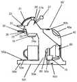
도 1 은 본 발명에 따른 음료 제조 장치의 측면도이다.
도 2 는 상기 장치의 주입 부재의 바람직한 실시형태의 사시 단면도이다.
도 3 은 연결 메카니즘을 통하여 상기 장치에 연결되어 있을 때 주입 부재의 바람직한 실시형태의 단면도이다.
도 4 는 캡슐 홀더 및 주입 부재를 유입하기 위한 틈을 갖는 기계의 추출 헤드의 측면도이다.
도 5 는 폐쇄 작동 위치에 있을 때 추출 헤드의 전방 커버 및 틈의 바람직한 실시형태의 정면도이다.
도 6 은 개방 작동 위치에 있을 때 추출 헤드의 전방 커버 및 틈의 바람직한 실시형태의 정면도이다.
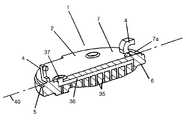
도 7 은 상기 장치의 주입 부재의 다른 실시형태의 사시 단면도이다.
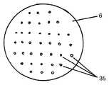
도 8 은 도 7 의 주입 부재의 주입 측을 나타내는 도면이다.1 is a side view of a beverage production apparatus according to the present invention.
2 is a perspective cross-sectional view of a preferred embodiment of the injection member of the device.
3 is a cross-sectional view of a preferred embodiment of the injection member when connected to the device via a coupling mechanism.
4 is a side view of the extraction head of the machine with a gap for introducing the capsule holder and the injection member.
5 is a front view of a preferred embodiment of the front cover and the gap of the extraction head when in the closed operating position.
6 is a front view of a preferred embodiment of the front cover and the gap of the extraction head when in the open operating position.
7 is a perspective cross-sectional view of another embodiment of an injection member of the device.
FIG. 8 is a view showing the injection side of the injection member of FIG. 7.
도 1 은 본 발명에 따른 음료 제조 장치 (50) 의 측면도이다. 이 장치 (50) 는 적어도 히터 (60), 펌프 (70) 및 제어 수단 (80) 을 포함하고 있는 하우징 (50a) 을 포함한다. 또한 이 장치는 이 장치에 연결되는 저장소 (40), 추출 헤드 (20) 및 이 장치가 안정적인 방식으로 서 있게 하기 위한 받침부가 제공되는 베이스 (50f) 를 포함한다. 이 장치는 또한 리셉터클이 위치되는 그리드 (50g) 가 제공되는 상부 표면 (50e) 을 갖는, 컵과 같은 리셉터클을 위한 스탠드 (50d) 를 포함한다.1 is a side view of a
물과 같은 액체를 히터 (60) 및 펌프 (70) 에, 그리하여 장치 (50) 의 추출 헤드 (20) 및 주입 부재 (10) (도 1 에 도시되지 않음) 에 공급하기 위해 저장소 (40) 가 제공된다. 바람직하게는, 저장소 (40) 는 분리 가능한 방식으로 이 장치에 연결되고 액체를 삽입하기 위해 입구 (40b) 를 갖는다. 바람직하게는 저장소 (40) 의 취급을 용이하게 하기 위해 손잡이 (40a) 가 저장소에 제공된다. 따라서 사용자가 저장소 (40) 를 편리한 방식으로 취급할 수 있다. 바람직하게는 저장소 (40) 의 바닥부에 위치되는 출구 (40c) 가 저장소 (40) 와 이 장치 (50) 사이의 연결을 가능하게 한다.The
추가로 또는 대안으로서, 통합된 저장소 (40) 대신에 또한 외부 물 공급부가 제공될 수 있다는 것을 알아야 한다.In addition or as an alternative, it should be appreciated that an external water supply may also be provided in place of the
이 장치의 추출 헤드 (20) 는 장치 (50) 에 제공되는 캡슐 (24) 을 선택적으로 에워싸기 위한 폐쇄 메카니즘 (21) 그리고 추출 헤드 (20) 그리고 캡슐 (24) 에 차가운 또는 뜨거운 물을 선택적으로 공급하기 위한 제어 레버 (27) 를 포함한다. 이에 의해, 제어 레버 (27) 는 적어도 장치 (50) 의 제어 수단 (80) 에 연결된다. 그러므로, 제어 레버 (27) 는 장치 (50) 의 전방-후방 방향으로 볼 때 제어 레버 (27) 를 좌측 또는 우측으로 이동시킴으로써 중립 위치로부터 뜨거운 물을 선택하는 제 1 위치 또는 차가운 물을 선택하는 제 2 위치로 스위치될 수 있다. 따라서, 사용자가 차가운 또는 뜨거운 음료를 제조하기 위해 장치에 제공되는 캡슐에 차가운 또는 뜨거운 물을 공급하는 것을 선택할 수 있다. 제어 레버 (27) 의 운동을 가능하게 하기 위해 장치 (50) 의 하우징 (50a) 은 이 장치의 추출 헤드 (20) 에 홈 (27a) 을 제공한다.The
도 1 에서 볼 수 있듯이, 캡슐 홀더 (30) 가 캡슐 (24) 을 수용하기 위한 유지 수단 (33) 에 의해 수용되는 캡슐 (24) 을 추출 헤드 (20) 의 수용 챔버 (25) (도 1 에 도시되지 않음) 에 제공하기 위해 추출 헤드 (20) 의 틈 (22) 안으로 삽입된다. 캡슐 (24) 을 수용하기 위한 유지 수단 (33) 은 캡슐 (24) 의 음료 전달 부분 (24a), 예컨대 출구 포트가 에워싸이지 않도록 설계된다. 액체를 캡슐 (24) 안으로 유입할 때, 자가 개방 하부면은 캡슐 (24) 내의 상승하는 압력에 의해 캡슐에서 개방되고 그러므로 음료를 예컨대 캡슐 (24) 아래에 놓인 리셉터클에 제공한다. 또한, 손잡이 (32) 가 캡슐 홀더 (30) 의 편리한 취급을 가능하게 하기 위해 캡슐 홀더 (30) 에 연결된다. 또한, 캡슐 홀더 (30) 에는, 캡슐 홀더가 상기 틈 (22) 안으로 삽입될 때 틈 (22) 을 커버하는 전방 커버 (31) 가 비치된다.As can be seen in FIG. 1, the
이 장치는 또한 메인 스위치 (50b) 그리고 사용자에게 장치 (50) 의 작동 상태를 알려줄 수 있는 다수의 제어 표시기 (50c) 를 포함한다.The device also includes a
도 2 는 주입 부재 (1) 의 바람직한 실시형태의 사시 측단면도이다. 주입 부재 (1) 는 바람직하게는 디스크 형상이고 플라스틱 재료, 이녹스 (inox) 또는 알루미늄 합금과 같은 금속으로 제조된 지지 부재 (2) 를 포함한다. 도 2 에 나타낸 바람직한 실시형태에서, 지지 부재 (2) 는 2 개의 디스크 형상 부재 (2a 및 2b) 로 이루어진다. 상기 2 개의 디스크 형상 부재 (2a, 및 2b) 는 동심으로 구성되고 바람직하게는 서로 영구적으로 연결된다. 2 개의 디스크 형상 부재 (2a, 2b) 는 상이한 재료일 수 있다.2 is a perspective side cross-sectional view of a preferred embodiment of the
지지 부재 (2) 는 상부면 (7) 과 하부면 (6) 을 포함한다. 상부면 (7) 은 바람직하게는 평면이다. 상부 및 하부면 (7 및 6) 은 서로 나란할 수 있다. 도 2 에 나타낸 것과 같이, 하부면 (6) 의 부분 (6b) 은 또한 하부면 (6) 으로부터 하방으로 돌출하거나 또는 볼록할 수 있다. 따라서, 도 2 에 따른 하부면 (6) 의 아래에 놓인 캡슐은 우려내기 위치일 때 효과적으로 약간 압축될 수 있다. 또한, 이러한 돌출부 (6b) 를 갖는 하부면 (6) 의 나타낸 실시형태는 동시 계류중인 2007년 3월 6일에 출원된 유럽 특허 출원 제 07103613.1 에 기재된 것과 같은 "웨일 (whale) 효과" 를 줄이기 위해, 지지부의 아래에 놓인 캡슐의 내부 용적을 줄일 수 있다.The
지지 부재 (2) 는 또한 원형 홈 (5) 을 포함한다. 따라서, 추출 헤드 (20) 의 지지부 (10) 에 연결될 때, 상기 지지부 (10) 내의 주입 부재 (1) 의 정확한 끼워 맞춤이 보장될 수 있다.The
주입 부재 (1) 는 또한 지지 부재 (2) 에 연결되는 바늘 요소 (3) 를 포함한다. 바늘 요소 (3) 는 바람직하게는 스테인리스 강으로 만들어진다. 바늘 요소는 지지 부재 (2) 에 의해 규정된 위치에 유지된다. 이는 지지 부재 (2) 의 하부면 (6) 과 상부면 (7) 사이에 관통 채널 (3c) 을 형성하도록 위치된다. 바늘 요소 (3) 는 기저 부분 (3b) 과 말단 부분 (3a) 을 포함한다. 바늘 요소 (3) 의 말단 부분 (3a) 은 지지 부재 (2) 의 상부면 (7) 과 수직인 하부면 (6) 으로부터 돌출한다. 이는 따라서 캡슐 (24) 을 관통하거나, 또는 결과적으로는 지지 부재 (2) 의 하부면 (6) 에 제공되는 캡슐의 입구 포트를 통하여 끼워 맞춤되도록 설계된다.The
지지 부재 (2) 의 상부면 (7) 에 위치되는 기저 부분 (3b) 의 오리피스에, 밀봉 수단 (3d) 이 제공된다. 이러한 밀봉 수단 (3b) 은, 추출 헤드 (20) 의 지지부 (10) 에 연결되어 있을 때, 추출 헤드 (20) 로부터 주입 부재 (1) 에 공급되는 액체의 누수를 방지한다. 바람직하게는, 밀봉 수단 (3d) 은 o-링 등을 포함한다.In the orifice of the base portion 3b located on the
지지 부재 (2) 의 하부면 (6) 의 부분 (6a) 이 바람직하게는 바늘 요소 (3) 의 말단 부분 (3a) 의 오리피스를 향하여 돌출한다. 따라서, 바늘 요소 (3) 가 캡슐 (24) 안으로 관통되고 액체가 상기 캡슐 (24) 안으로 공급될 때, 캡슐 (24) 의 상부면과 바늘 요소 (3) 의 효과적인 밀봉이 달성될 수 있다. 특히, 돌출부 (6a) 가 바늘 요소와 캡슐의 표면 사이의 밀봉 끼움을 생성하기 위해 캡슐의 가요성 표면과 맞물릴 수 있고, 결국 하방으로 변형될 수 있다. 캡슐이 주입되는 유체의 압력 하에 놓일 때 유체 기밀 밀봉이 생성될 수 있는데 이는 가요성 표면이 표면 부분 (6a 및 6b) 의 형상과 양호하게 매치될 수 있기 때문이다.The
바람직하게는, 바늘 요소 (3) 의 내경은 1 ㎜ 미만이다. 더 바람직하게는, 직경은 전달되는 액체를 위한 모세관 직경, 예컨대 0.3 ㎜ 미만이다. 지지 부재 (2) 로부터 돌출하는 말단 부분 (3a) 의 길이는 바람직하게는 3 ㎜ 미만이다.Preferably, the inner diameter of the
또한, 주입 부재 (1) 는 음료 제조를 위한 장치의 추출 헤드 (20) 의 지지부 (10) 와 주입 부재 (1) 사이의 연결을 가능하게 하는 해제 가능한 연결 메카니즘 (4) 을 포함한다. 연결 메카니즘 (4) 은 적어도 하나의 후크형 부재 (4b) 를 포함하고 이는 지지 부재 (2) 의 통합된 부분이며 지지 부재의 상부면 (7) 으로부터 돌출한다. 도 2 에 따른 바람직한 실시형태에서, 2 개의 후크형 부재 (4b) 가 지지 부재 (2) 에 제공된다. 이에 의해, 후크형 부재 (4b) 는 지지 부재 (2) 의 중심선 (40) 으로부터 거리 (c) 로 이격된다. 중심선 (40) 은 지지 부재 (2) 의 상부면 (7) 과 동일 평면에 위치된다. 도 2 에 나타낸 것과 같이, 후크형 부재 (4b) 와 원형 홈 (5) 사이에 위치되는 상부면 (7) 의 외부 부분 (7a) 이 하부면 (6) 을 향해 기울어져 있다. 이러한 실시형태는, 주입 부재 (1) 가 지지부 (10) 의 제공되는 연결 수단 안에 걸려야만 하기 때문에, 추출 헤드 (20) 의 지지부 (10) 와 후크형 부재 (4b) 사이의 연결을 용이하게 한다.The
게다가, 연결 메카니즘 (4) 은 래치 부재 (4a) 를 포함하며 이는 지지 부재 (2) 의 통합된 부분으로서 또한 형성되고 지지 부재의 상부면 (7) 으로부터 돌출한다. 도 2 에 나타낸 것과 같이, 래치 부재 (4a) 와 후크형 부재 (4b) 는 바람직하게는 주입 부재 (1) 의 중심선 (40) 의 대향하는 단부에 위치된다. 바람직하게는, 래치 부재 (4a) 는 예컨대 돌출하는 래치 부재 등을 연결하기 위해 틈 (4c) 을 포함한다. 상기 틈 (4c) 위에 위치되는 래치 부재 (4a) 의 단부는 바람직하게는 주입 부재 (1) 와 연결되도록 의도되는 지지부의 상호 보완적인 래치 연결 부재 (12) 를 안내하기 위해 기울어진 부분 (4d) 을 포함한다. 따라서, 래치 부재와 같은 추출 헤드 (20) 의 연결 수단은 상기 틈 (4c) 을 사용하여 주입 부재 (1) 와 용이하게 연결될 수 있다.In addition, the connecting
도 3 은 추출 헤드 (20) 에 연결되는 지지부 (10) 를 사용하여 추출 헤드 (20) 의 내측에 연결되는 주입 부재 (1) 를 나타내는 도면이다. 지지부 (10) 와 주입 부재 (1) 사이의 연결은 연결 메카니즘 (4) 을 사용하여 수립된다. 이에 의해, 주입 부재 (1) 의 상부면 (7) 은 지지부 (10) 의 면 (10a) 과 접한다. 주입 부재 (1) 의 원형 홈 (5) 은 지지부 (10) 의 내측에 형성되는 원형 홈 (5a) 에 끼워 맞춤된다. 이러한 실시형태는 지지부 (10) 에 주입 부재 (1) 의 정확하고 중심 맞춤된 끼움을 보장한다. 물론, 홈 (5) 은 원형 외의 다른 형상을 가질 수 있다.3 is a view showing an
원형 리세스 (9b) 가 지지부 (10) 의 면 (10a) 에 형성된다. 상기 리세스 (9b) 는 지지부 (10) 에 의해 수용되는 공급부 (9a) 와 연결된다. 주입 부재 (1) 가 지지부 (10) 에 연결될 때, 바늘 요소 (3) 의 채널 (3c) 과 공급부 (9a) 는 정렬하게 된다. 이에 의해, 원형 리세스 (9b) 는 바늘 요소 (3) 의 기저 부분 (3b) 에 연결되는 밀봉 수단 (3d) 을 수용하도록 설계된다. 따라서, 공급부 (9a) 및 바늘 요소 (3) 의 효과적인 밀봉이 얻어진다. 따라서, 공급부 (9a) 에 제공되는 액체가 바늘 요소 (3) 의 채널 (3c) 로 전달된다. 그러므로, 액체는 바늘 요소 (3) 의 말단 부분 (3a) 을 통하여 효과적으로 방출될 수 있다.A
또한, 리세스 (8) 는 공급부 (10) 의 면 (10a) 에 제공된다. 상기 리세스 (8) 는 주입 부재 (1) 의 후크형 부재 (4b) 를 수용하기 위해 형성된다. 이에 의해, 러그 (8a) 가 도 3 에 나타낸 것과 같이 주입 부재 (1) 의 후크형 부재 (4b) 와 리세스 (8) 의 연결을 가능하게 하기 위해 리세스 (8) 에 제공된다.The
또한, 래치 연결 부재 (12) 가 주입 부재 (1) 의 래치 부재 (4a) 와 연결을 수립하기 위해 지지부 (10) 의 틈 (10b) 에 제공된다. 래치 부재 (12) 는 지지부 (10) 에 해제 가능하게 장착되는 이녹스 재료와 같은 금속의 스프링일 수 있다. 그의 하부 단부 (12a) 에서, 상기 래치 부재 (12) 는 후크형 방식으로 구부러진다. 따라서, 후크형 단부 (12a) 는 주입 부재 (1) 의 래치 부재 (4a) 의 틈 (4c) 에 연결될 수 있다. 래치 부재 (12) 의 후크형 단부에 연결될 때, 주입 부재 (1) 의 래치 부재 (4a) 의 기울어진 부분 (4b) 은 후크형 단부 (12a) 와 틈 (4c) 의 맞물림을 용이하게 한다.In addition, a
또한, 틈 (13) 이 지지부 (10) 의 측면에 제공된다. 상기 틈 (13) 은 바람직하게는 원형이다. 지지부 (10) 의 틈 (10b) 과 틈 (13) 은 연결된다. 도 3 에 따른 바람직한 실시형태에서, 틈 (13) 은 래치 부재 (12) 의 후크형 단부 (12a) 와 동일한 높이가 되도록 놓인다. 따라서, 도 3 에 나타낸 것과 같이 주입 부재 (1) 가 지지부 (10) 에 연결될 때, 틈 (13) 은 주입 부재 (1) 의 래치 부재 (4d) 의 틈 (4c) 과 정렬하게 된다. 따라서, 틈 (13) 을 통하여 래치 부재 (12) 에 접근하는 것이 가능하다. 따라서, 사용자가 지지부 (10) 로부터 주입 부재 (1) 를 분리시키기 위해 래치 부재를 내방으로 밀기 위해 틈 (13) 을 통하여 끼워지는 공구를 삽입함으로써 래치 부재 (12) 를 해제할 수 있다.In addition, a
도 4 는 음료 제조 장치의 추출 헤드 (20) 를 나타내는 도면이다. 상기 추출 헤드 (20) 는 추출 헤드 (20) 의 내측에 수용 챔버 (25) 를 그리고 그의 전방측에 수용 챔버 (25) 에 접근하기 위한 틈 (22) 을 포함한다. 추출 헤드 (20) 는 사용자가 수용 챔버 (25) 에 제공되는 캡슐 (24) 을 선택적으로 에워싸는 것을 가능하게 하는 폐쇄 메카니즘 (21) 을 또한 포함한다. 이에 의해, 폐쇄 메카니즘 (21) 은 수용 챔버 (25) 의 후방 벽 (25b) 과 지지부 (10) 의 상대 운동을 가능하게 한다. 지지부 (10) 는 아래로부터 추출 헤드의 돔 형상 부재 (20a) 에 연결된다. 폐쇄 메카니즘 (21) 이 사용자에 의해 작동될 때, 지지부 (10) 는 높아진 개방 위치로부터 추출 헤드 (20) 의 내측에 제공되는 안내 리세스 (25a) 를 향하여 낮아진다. 상기 안내 리세스 (25a) 는 그의 삽입 동안 수용 챔버 안으로 미끄러질 때 캡슐 홀더를 안내하고 캡슐 홀더 (30) 를 수용 챔버 (25) 내의 그의 정확한 위치에 유지하도록 설계된다. 따라서, 캡슐 홀더 (30) 에 의해 유지되는 캡슐 (24) 이 폐쇄 메카니즘 (21) 을 통하여 수용 챔버 (25) 내에 효과적으로 에워싸일 수 있다.4 is a view showing the
캡슐 홀더 (30) 는 캡슐 (24) 을 수용하기 위해 설계되는 하우징 (33) 을 포함한다. 또한, 캡슐 홀더 (30) 는 손잡이 (32) 를 포함한다. 손잡이 (32) 는 캡슐 홀더 (30) 로부터 수평으로 돌출한다. 따라서, 캡슐 홀더 (30) 가 추출 헤드 (20) 안으로 완전히 삽입되더라도, 손잡이 (32) 가 캡슐 홀더 (30) 를 추출 헤드 (20) 의 틈 (22) 으로부터 빼내는데 사용될 수 있다. 캡슐 홀더는 하우징 (33) 과 손잡이 (32) 사이에 위치되는 커버 부재 (31) 를 또한 포함한다. 캡슐 홀더 (30) 가 추출 헤드 (20) 안으로 완전히 삽입될 때, 커버 부재 (31) 는 추출 헤드 (20) 의 틈 (22) 을 완전히 커버하고, 이에 의해 추출 헤드 (20) 의 내측에서 수용 챔버 (25) 를 에워싼다.
도 4 는 폐쇄 메카니즘 (21) 이 개방 상태일 때 지지부 (10) 의 위치를 나타낸다. 따라서, 지지부 (10) 는 폐쇄 메카니즘 (21) 의 폐쇄 상태와 비교하여 높아진 위치에 위치된다. 도면에서 볼 수 있듯이, 주입 부재 (1) 의 래치 부재 (12a) 에 접근하기 위한 지지부 (10) 의 틈 (13) 은, 폐쇄 메카니즘 (21) 이 개방 상태일 때 추출 헤드 (20) 의 전방 커버 부재 (23) 에 의해 커버된다. 따라서, 래치 부재 (12a) 는 폐쇄 메카니즘 (21) 이 개방 상태일 때에는 접근될 수 없다. 또한, 캡슐 홀더 (30) 가 추출 헤드 (20) 의 틈 (22) 안으로 삽입될 때, 틈 (13) 은 캡슐 홀더의 커버 부재 (31) 가 추출 헤드 (20) 의 틈 (22) 을 완전히 커버하기 때문에 또한 접근할 수 없다. 그러므로, 사용자는 폐쇄 메카니즘 (21) 이 개방 상태가 아니고 캡슐 홀더 (30) 가 추출 헤드 (20) 의 틈 (22) 안으로 삽입되지 않을 때에만 래치 부재 (12a) 에 접근하는 것이 가능하다.4 shows the position of the
사용자가 주입 부재 (1) 를 추출 헤드 (20) 의 지지부 (10) 에 연결하고자 할 때, 캡슐 홀더 (30) 는 틈 (22) 으로부터 제거되어야만 하고 따라서 먼저 추출 헤드 (20) 로부터 제거된다. 또한, 지지부 (10) 를 낮아지게 하고 그러므로 주입 부재 (1) 를 지지부 (10) 에 연결하기 위해 추출 헤드 (20) 의 폐쇄 메카니즘 (21) 은 폐쇄 위치가 되어야만 한다.When the user wishes to connect the
또한, 지지부 (10) 에는 지지부 (10) 에 연결될 때 주입 부재 (1) 의 존재를 탐지하는 센서 (26) 가 제공된다. 센서 (26) 는 주입 부재 (1) 가 지지부 (10) 에 연결되었는지 아닌지를 탐지하는데 적합한, 근접 센서 (proximity sensor) 등 일 수 있다. 센서 (26) 의 위치는 도 4 에 나타낸 실시형태로부터 변할 수 있다.The
바람직하게는, 제어 수단 (80) 은 주입 부재 (1) 의 존재가 센서 (26) 에 의해 탐지될 때에만, 펌프 (70) 를 스위칭함으로써, 지지부 (10) 에 의해 수용되는 공급부 (9b) 에 액체를 제공한다. 따라서, 이 장치는 주입 부재 (1) 가 지지부 (10) 에 연결될 때 음료 제조를 위해서만 사용될 수 있다. 물론 주입 부재 (1) 가 지지부 (10) 에 연결되지 않을 때 액체가 공급부 (9b) 그리고 주입 부재 (1) 에 공급되는 것이 또한 가능할 수 있다.Preferably, the control means 80 switches the
도 5 는 추출 헤드 (20) 의 폐쇄 메카니즘 (21) 이 폐쇄 상태일 때, 틈 (22) 에 제공되는 캡슐 홀더가 없는 추출 헤드 (20) 의 전방을 나타내는 도면이다. 따라서, 지지부 (10) 는 그의 낮은 위치로 있고 그러므로, 래치 연결 메카니즘 (4a, 12a) 에 접근하기 위한 틈 (13) 은 접근 가능하다. 따라서, 폐쇄 메카니즘 (21) 의 폐쇄 상태에서, 추출 헤드 (20) 의 전방 커버 부재 (23) 는 래치 연결 메카니즘 (4a, 12a) 에 접근하기 위한 틈 (13) 을 커버하지 않는다. 그러므로, 사용자가 래치 연결 메카니즘 (4a, 12a) 을 해제함으로써 지지부 (10) 로부터 주입 부재 (1) 를 연결 해제시킬 수 있다.5 shows the front of the
추출 헤드 (20) 의 지지부 (10) 로부터 연결 해제될 때, 주입 부재 (1) 는 추출 헤드 (20) 의 수용 챔버 (25) 안으로 떨어진다. 주입 부재 (1) 를 연결 해제한 이후, 사용자가 주입 부재 (1) 를 수용 챔버 (25) 로부터 제거할 수 있다.When disconnected from the
도 6 은 폐쇄 메카니즘 (21) 이 개방 상태일 때, 추출 헤드 (20) 의 틈 (22) 에 제공되는 캡슐 홀더가 없는 추출 헤드 (2) 의 전방에 관한 도면이다. 도 6 으로부터 볼 수 있듯이, 폐쇄 메카니즘 (21) 의 이러한 상태에서, 틈 (13) 은 접근 가능하지 않다. 따라서, 주입 부재 (1) 는 추출 헤드 (20) 의 전방 커버 (23) 가 틈 (13) 을 커버하기 때문에 제거될 수 없다.FIG. 6 is a view of the front of the
따라서, 폐쇄 메카니즘은 수용 챔버 (25) 가 폐쇄되고 동시에 캡슐 홀더 (30) 가 이전에 제거될 때에만 주입 부재 (1) 가 해제될 수 있다는 것을 보장한다. 단지 이러한 조건 하에서, 주입 부재 (1) 를 차단하는 래치 (12a) 가 해제될 수 있는 틈 (13) 은 외측으로부터 접근 가능하다.Thus, the closing mechanism ensures that the
따라서, 단지 캡슐 홀더 (30) 가 없는 수용 챔버 (25) 의 폐쇄 위치에서 주입 부재 (1) 가 제거될 수 있다는 것이 보장된다. 이는 사용자가 수용 챔버 (25) 내의 캡슐 홀더 (30) 의 차단을 유도할 수 있는, 캡슐 홀더 (30) 가 존재하는 동안 주입 부재 (1) 를 해제하려고 할 때의 문제를 회피한다.Thus, it is ensured that the
도 7 에 나타낸 다른 바람직한 실시형태에서, 주입 부재 (1) 의 지지 부재 (2) 에는 일련의 주입 구멍 (35) 을 포함하는 주입 요소가 구비된다. 이에 의해, 일련의 주입 구멍 (35) 은 공통 매니폴드 (36) 를 통하여 지지 부재 (2) 에 공통의 액체 입구 (37) 에 연결된다. 따라서, 각각의 주입 구멍 (35) 은 공통 매니폴드 (36) 에 연결된다. 그러므로, 주입 부재 (1) 의 입구 (37) 에 공급되는 액체는 공통 매니폴드 (36) 를 통하여 일련의 주입 구멍 (35) 에 효과적으로 분산될 수 있다. 따라서, 액체 샤워가 주입 구멍 (35) 에 의해 형성될 수 있고 그러므로 이 장치의 수용 챔버 (25) 내에 놓이는 캡슐 등에 물을 공급한다.In another preferred embodiment shown in FIG. 7, the
도 8 로부터 볼 수 있듯이, 일련의 주입 구멍 (35) 은 지지 부재 (2) 의 하부면 (6) 에 위치된다. 바람직하게는, 일련의 주입 구멍 (35) 은 지지 부재 (2) 의 하부면 (6) 에 걸쳐 동일하게 분산된다. 더 바람직하게는, 구멍은 동일한 직경이다. 이에 의해, 구멍 (35) 의 직경 및 개수, 뿐만아니라 구멍 (35) 사이의 거리는 주입 요소 (35) 에 의해 제공되는 액체와 예컨대 캡슐에 의해 제공되는 성분 사이의 상호 작용의 공정에 대한 상이한 요구 사항을 충족시키기 위해 변할 수 있다. 따라서, 예컨대 GB2437483 에 설명되는 낮은 또는 중간 압력으로 캡슐에 걸쳐 균일하게 분산되는 액체를 제공하는 것이 가능하다. 바람직하게는, 일련의 주입 구멍에 의해 제공되는 액체는 8.5 바 미만의 압력의 액체이다. 필터 팟 등과 같은 개방 캡슐이 주입 부재 (1) 에 연결되기 위해 이 장치의 수용 챔버 (25) 안으로 삽입될 수 있다. 그러므로, 주입 구멍 (35) 을 통하여 캡슐에 공급되는 균일하게 분산된 액체는 개방 캡슐에 담겨있는 성분과 상호 작용하게 된다. 캡슐에 의해 제공되는 성분은 예컨대 볶은 또는 분쇄 커피, 잎 차, 허브 차 또는 과일 차 또는 음료를 제조하기 위해 액체와 상호 작용하게 될 수 있는 어떠한 다른 성분일 수 있다.As can be seen from FIG. 8, a series of injection holes 35 is located in the
본 발명이 그의 바람직한 실시형태를 참조하여 설명되었지만, 많은 변경 및 변화가 첨부된 청구항에 의해 규정되는 본 발명의 범위를 벗어나지 않으면서 업계에서 보통의 기술을 가진 사람에 의해 이루어질 수 있다. 예컨대, 덕트 등을 통하여 연결될 수 있는 하나보다 많은 바늘 요소 (3) 를 갖는 주입 부재 (1) 를 설계하는 것이 가능하다. 이러한 바늘 요소 (3) 의 디자인 및 패턴은 제조되는 음료의 주입 조건에 대하여 상이한 요구 사항을 충족시키기 위해 변할 수 있다. 이에 의해, 주입 조건은 특히 캡슐 (24) 내에 제공되는 물질의 추출 및/또는 용해에 대하여 변할 수 있다.Although the invention has been described with reference to its preferred embodiments, many changes and modifications can be made by a person of ordinary skill in the art without departing from the scope of the invention as defined by the appended claims. For example, it is possible to design an
다른 실시형태에서, 지지부 (10) 에 연결되는 주입 부재 (1) 의 종류를 탐지하는 센서 (26) 를 제공하는 것이 또한 가능할 수 있다. 따라서, 상이한 실시형태의 주입 부재를 연결할 때, 센서 (26) 는 지지부 (10) 에 연결되는 주입 요소의 종류에 대한 정보를 전달할 수 있다. 이는 이 장치의 제어 유닛이 특정한 주입 요소의 탐지에 대응하여 음료 제조의 작동 파라미터를 설정할 수 있는 이점을 갖는다. 예컨대, 차의 제조를 위해 가장 적합하게 설계된 주입 요소가 커피의 제조를 위한 최상의 주입 파라미터를 제공하기 위해 설계되는 주입 요소와 구분될 수 있다. 따라서, 추출 시간, 추출 압력 및/또는 추출 온도 등이 확인되는 주입 요소에 따라 설정될 수 있다. 이를 위해, 연결된 주입 요소를 확인하기 위해 이 장치에 제공되는 센서에 정보를 전달할 수 있는 전달기 등과 같은 수단을 갖는 주입 요소를 제공하는 것이 또한 가능하다.In another embodiment, it may also be possible to provide a
게다가, 추출 헤드의 지지부에 제공되는 연결 메카니즘은 다른 요소를 추출 헤드 (20) 에 연결하는데 사용될 수 있다. 예컨대 우유의 거품을 형성하는데 사용되도록 설계되는 요소를 지지부에 연결하는 것이 가능할 수 있다. 따라서, 이러한 요소는 제공되는 지지부에 의해 수용되는 기재된 공급부 외에 액체의 제 2 또는 심지어 제 3 공급부에 연결될 수 있다.In addition, a coupling mechanism provided on the support of the extraction head can be used to connect other elements to the
Claims (25)
Translated fromKorean상기 추출 헤드 (20) 는 상기 장치의 수용 챔버 (25) 안으로 캡슐 (24) 을 삽입하기 위한 틈 (22) 을 갖고,
상기 폐쇄 메카니즘 (21) 은 적어도 2 개의 에워싸기 부재 (10, 30) 의 상대 운동에 의해 상기 캡슐 (24) 을 선택적으로 에워싸고,
상기 적어도 하나의 주입 부재 (1) 는 지지 부재 (2) 및, 액체를 수용하기 위해 상기 지지 부재 (2) 에 부착되는 적어도 하나의 주입 요소 (3) 를 포함하고, 상기 주입 요소는 상기 장치 (50) 에 제공되는 캡슐 (24) 안으로 액체를 주입하도록 구성되며, 상기 주입 부재 (1) 는 해제 가능한 연결 메카니즘 (4a, 4b, 12) 을 통하여 상기 수용 챔버 (25) 의 주입 측에서 지지부 (10) 에 해제 가능하게 장착되는 음료를 제조하기 위한 장치.An apparatus for preparing a beverage from a food substance contained in the capsule 24 by injecting a liquid into a capsule 24 provided in the apparatus 50 for preparing a beverage from the food substance, the apparatus comprising: an extraction head 20 A closing mechanism 21 and at least one injection member 1,
The extraction head 20 has a gap 22 for inserting the capsule 24 into the receiving chamber 25 of the device,
The closing mechanism 21 selectively surrounds the capsule 24 by the relative movement of at least two enclosing members 10, 30,
The at least one injection member 1 comprises a support member 2 and at least one injection element 3 attached to the support member 2 for receiving a liquid, the injection element comprising the device ( Configured to inject liquid into the capsule 24 provided in the capsule 50, wherein the injection member 1 is supported at the injection side of the receiving chamber 25 via a releasable connection mechanism 4a, 4b, 12. ) Releasably mounted.
상기 주입 요소 (3) 는 추출 헤드의 수용 챔버 (25) 안으로 돌출하는 바늘인 음료를 제조하기 위한 장치.The method of claim 1,
The injection element (3) is a device for producing a beverage which is a needle protruding into the receiving chamber (25) of the extraction head.
상기 주입 요소 (3) 는 주입 부재 (1) 의 주입 측에서 액체 샤워를 형성하는 일련의 주입 구멍인 음료를 제조하기 위한 장치.The method of claim 1,
The injection element (3) is a series of injection holes for forming a liquid shower at the injection side of the injection member (1).
상기 일련의 주입 구멍 (35) 은 공통 매니폴드 (36) 를 통하여 지지 부재 (2) 에서 공통의 액체 입구 (37) 에 연결되는 음료를 제조하기 위한 장치.The method of claim 3, wherein
The series of injection holes (35) is connected to a common liquid inlet (37) in the support member (2) via a common manifold (36).
상기 해제 가능한 연결 메카니즘은 주입 부재 (1) 를 지지부 (10) 에 제거 가능하게 잠그기 위한 래치 메카니즘 (4a, 4c, 4d, 12, 12a) 을 포함하는 음료를 제조하기 위한 장치.The method according to any one of claims 1 to 4,
The releasable connection mechanism comprises a latch mechanism (4a, 4c, 4d, 12, 12a) for removably locking the infusion member (1) to the support (10).
상기 액체는 상기 장치의 펌프 (70) 에 의해 캡슐 (24) 에 제공되는 음료를 제조하기 위한 장치.6. The method according to any one of claims 1 to 5,
The liquid is provided to the capsule (24) by a pump (70) of the device.
상기 장치 (50) 는 상기 장치 (50) 의 추출 헤드 (20) 에 캡슐 (24) 을 제공하기 위해 캡슐 홀더 (30) 를 또한 포함하고, 상기 캡슐 홀더 (3) 는 추출 헤드 (20) 의 틈 (22) 안으로 삽입되는 음료를 제조하기 위한 장치.The method according to any one of claims 1 to 6,
The device 50 also includes a capsule holder 30 for providing a capsule 24 to the extraction head 20 of the device 50, the capsule holder 3 having a gap in the extraction head 20. (22) A device for producing a beverage to be inserted into.
상기 주입 부재 (1) 는 추출 헤드 (20) 의 틈 (22) 을 통하여 상기 장치의 수용 챔버 (25) 안으로 삽입되거나 또는 이로부터 제거되는 음료를 제조하기 위한 장치.The method according to any one of claims 1 to 7,
The injection member (1) is inserted into or removed from the receiving chamber (25) of the device through the gap (22) of the extraction head (20).
상기 주입 부재 (1) 는 아래로부터 추출 헤드 (20) 에 연결되는 지지부 (10) 에 연결되는 음료를 제조하기 위한 장치.The method according to any one of claims 1 to 8,
The injection member (1) is for producing a beverage connected to a support (10) connected to the extraction head (20) from below.
상기 주입 부재 (1) 의 지지 부재 (2) 는 링 형상 디스크 부재인 음료를 제조하기 위한 장치.The method according to any one of claims 1 to 9,
Apparatus for producing a beverage wherein the support member (2) of the infusion member (1) is a ring-shaped disk member.
상기 해제 가능한 연결 메카니즘 (4a, 4b, 12a) 의 적어도 하나의 부분은 추출 헤드 (20) 의 지지부 (10) 안으로 리세스되는 음료를 제조하기 위한 장치.The method according to any one of claims 1 to 10,
At least one part of said releasable connection mechanism (4a, 4b, 12a) is recessed into the support (10) of the extraction head (20).
상기 해제 가능한 연결 메카니즘 (4a, 4b, 12a) 은 추출 헤드 (20) 의 지지부 (10) 의 상부 전방에 위치되는 음료를 제조하기 위한 장치.The method according to any one of claims 1 to 11,
The releasable connection mechanism (4a, 4b, 12a) is located in the upper front of the support (10) of the extraction head (20).
상기 연결 메카니즘 (4a, 12a) 은 지지부 (10) 의 개구 (13) 를 통하여 추출 헤드 (20) 의 외측으로부터 접근함으로써 해제될 수 있는 음료를 제조하기 위한 장치.The method according to any one of claims 1 to 12,
The connecting mechanism (4a, 12a) can be released by approaching from the outside of the extraction head (20) through the opening (13) of the support (10).
상기 폐쇄 메카니즘 (21) 은 추출 헤드 (20) 의 전방 커버 부재 (23) 와 지지부 (10) 의 개구 (13) 사이의 상대 운동을 가능하게 하는 음료를 제조하기 위한 장치.The method of claim 13,
The closing mechanism (21) is a device for producing a beverage which enables a relative movement between the front cover member (23) of the extraction head (20) and the opening (13) of the support (10).
상기 커버 부재 (23) 는 상기 장치의 폐쇄 메카니즘 (21) 이 개방 상태일 때 개구 (13) 를 커버하는 음료를 제조하기 위한 장치.The method of claim 14,
The cover member (23) is for producing a beverage for covering the opening (13) when the closing mechanism (21) of the device is open.
상기 개구 (13) 는 캡슐 홀더 (30) 가 추출 헤드 (20) 의 틈 (22) 에 삽입되지 않을 때에만 접근될 수 있는 음료를 제조하기 위한 장치.The method according to any one of claims 13 to 15,
The opening (13) is a device for producing a beverage which is accessible only when the capsule holder (30) is not inserted into the gap (22) of the extraction head (20).
센서 수단 (26) 이 상기 장치에 연결되는 주입 부재 (1) 의 존재를 탐지하는 음료를 제조하기 위한 장치.The method according to any one of claims 1 to 16,
Apparatus for producing a beverage in which sensor means (26) detect the presence of an infusion member (1) connected to the apparatus.
상기 센서 수단 (26) 은 주입 부재 (1) 의 존재가 탐지될 때 상기 장치 (50) 로부터 액체의 방출을 가능하게 하도록 설계되는 음료를 제조하기 위한 장치.The method of claim 17,
Said sensor means (26) is designed to enable the release of a liquid from said device (50) when the presence of an injection member (1) is detected.
상기 센서 수단 (26) 은 주입 부재 (1) 의 존재가 탐지되지 않을 때 상기 장치로부터 액체의 방출을 가능하게 하도록 설계되는 음료를 제조하기 위한 장치.The method of claim 17,
Said sensor means (26) are designed for enabling a release of liquid from said device when the presence of an injection member (1) is not detected.
지지 부재 (2) 및 압력 하의 액체를 수용하기 위해 부착되는 적어도 하나의 바늘 요소 (3) 를 포함하고, 상기 주입 부재 (1) 는 아래로부터 이러한 시스템 (50) 의 지지부 (10) 에 해제 가능한 연결을 위한 수단 (4a, 4b) 을 포함하는 제거 가능한 주입 부재 (1).Removable infusion member designed to be mounted to a system for making a beverage from the food substance contained in the capsule 24 by injecting liquid into the capsule 24 provided in the system 50 for making a beverage from the food substance ( 1), the injection member 1
A support member 2 and at least one needle element 3 attached to receive the liquid under pressure, the injection member 1 being releasable to the support 10 of this system 50 from below. Removable injection member 1 comprising means for the purpose 4a, 4b.
상기 지지 부재 (2) 는 링 형상 디스크 부재인 제거 가능한 주입 부재 (1).The method of claim 20,
The support member (2) is a removable injection member (1) which is a ring-shaped disk member.
상기 주입 부재 (1) 를 상기 시스템의 지지부 (10) 에 연결하기 위한 수단 (4a, 4b) 은 래치 부재인 제거 가능한 주입 부재 (1).The method of claim 20 or 21,
Removable injection member (1) wherein the means (4a, 4b) for connecting the injection member (1) to the support (10) of the system are latch members.
볼록한 부분 (6b) 이 바늘 요소 (3) 와 동일한 방향으로 주입 부재 (1) 의 하부면 (6) 으로부터 돌출하도록 설계되는 제거 가능한 주입 부재 (1).The method according to any one of claims 20 to 22,
Removable injecting member 1, wherein the convex portion 6b is designed to protrude from the lower surface 6 of the injecting member 1 in the same direction as the needle element 3.
Combination of device and filter pot according to claim 1.
Applications Claiming Priority (2)
| Application Number | Priority Date | Filing Date | Title |
|---|---|---|---|
| EP07123492.6 | 2007-12-18 | ||
| EP07123492AEP2071988B1 (en) | 2007-12-18 | 2007-12-18 | Device for preparing a beverage with removable injection member |
Publications (2)
| Publication Number | Publication Date |
|---|---|
| KR20100099727Atrue KR20100099727A (en) | 2010-09-13 |
| KR101590654B1 KR101590654B1 (en) | 2016-02-01 |
Family
ID=39472423
Family Applications (1)
| Application Number | Title | Priority Date | Filing Date |
|---|---|---|---|
| KR1020107015912AExpired - Fee RelatedKR101590654B1 (en) | 2007-12-18 | 2008-12-15 | Device for preparing a beverage with removable injection member |
Country Status (25)
| Country | Link |
|---|---|
| US (1) | US8443718B2 (en) |
| EP (1) | EP2071988B1 (en) |
| JP (1) | JP5414690B2 (en) |
| KR (1) | KR101590654B1 (en) |
| CN (1) | CN101945600B (en) |
| AR (1) | AR069819A1 (en) |
| AT (1) | ATE499865T1 (en) |
| AU (1) | AU2008337523B2 (en) |
| BR (1) | BRPI0821016A2 (en) |
| CA (1) | CA2708575C (en) |
| CL (1) | CL2008003816A1 (en) |
| DE (1) | DE602007012913D1 (en) |
| DK (1) | DK2071988T3 (en) |
| ES (1) | ES2359997T3 (en) |
| MX (1) | MX2010005981A (en) |
| MY (1) | MY153540A (en) |
| PL (1) | PL2071988T3 (en) |
| PT (1) | PT2071988E (en) |
| RU (1) | RU2484751C2 (en) |
| SI (1) | SI2071988T1 (en) |
| TW (1) | TWI469755B (en) |
| UA (1) | UA101347C2 (en) |
| UY (1) | UY31549A1 (en) |
| WO (1) | WO2009077489A1 (en) |
| ZA (1) | ZA201005085B (en) |
Families Citing this family (23)
| Publication number | Priority date | Publication date | Assignee | Title |
|---|---|---|---|---|
| EP2071986B1 (en) | 2007-12-18 | 2012-02-29 | Nestec S.A. | System for preparing a beverage from ingredients supported by an encoded insert |
| US20150125586A1 (en)* | 2010-05-03 | 2015-05-07 | Apiqe | Beverage system with flavor pod dispenser |
| PT2409608E (en)* | 2010-07-19 | 2013-07-26 | Nestec Sa | Device for sensing a capsule in a beverage production apparatus |
| EP2460449A1 (en) | 2010-12-06 | 2012-06-06 | Nestec S.A. | A beverage preparation machine with automatic cleaning system |
| US10034570B2 (en) | 2011-11-09 | 2018-07-31 | LaVit Technology LLC | Capsule based system for preparing and dispensing a beverage |
| US10080459B2 (en) | 2011-11-09 | 2018-09-25 | La Vit Technology Llc | Capsule-based system for preparing and dispensing a beverage |
| EP2612579A1 (en)* | 2012-01-05 | 2013-07-10 | Nestec S.A. | A beverage preparation machine |
| GB2499004A (en)* | 2012-02-02 | 2013-08-07 | Kraft Foods R & D Inc | Clamping mechanism for a beverage preparation machine |
| EP2638833A1 (en) | 2012-03-16 | 2013-09-18 | Nestec S.A. | A beverage preparation machine with cleanable brewing head |
| CA2905217C (en) | 2013-04-03 | 2016-11-08 | 2266170 Ontario Inc. | Capsule machine and components |
| US9320382B2 (en)* | 2013-07-15 | 2016-04-26 | La Vit Technology Llc | Capsule based system for preparing and dispensing a beverage |
| ITMO20130295A1 (en)* | 2013-10-17 | 2015-04-18 | Sarong Spa | DRINKING MACHINE FOR DRINKS |
| CN104188513B (en)* | 2014-06-23 | 2016-06-08 | 佛山市顺德区宏泽电器制造有限公司 | A kind of portable folding coffee brewing equipment |
| CN104433796B (en)* | 2014-10-22 | 2018-02-02 | 宁波全景电器技术有限公司 | The plate that rises brokenly for beverage brewing device |
| EP3175745A1 (en)* | 2015-12-01 | 2017-06-07 | Qbo Coffee GmbH | Brewing module, capsule sensor module and machine for making beverages |
| EP3199071B1 (en)* | 2016-01-27 | 2019-05-08 | Koninklijke Douwe Egberts B.V. | System for preparing a liquid beverage from a capsule |
| PT3509464T (en) | 2016-09-09 | 2021-10-13 | Nestle Sa | BEVERAGE MACHINE WITH ERGONOMIC HANDLING |
| CA3041722A1 (en) | 2016-11-09 | 2018-05-17 | Pepsico, Inc. | Carbonated beverage makers, methods, and systems |
| RU2769663C2 (en) | 2017-05-23 | 2022-04-04 | Сосьете Де Продюи Нестле С.А. | Beverage preparation device with improved pump control |
| EP3469962B1 (en) | 2017-10-11 | 2020-02-26 | Simonelli Group S.P.A. | Fast-uncoupling shower screen for espresso coffee machines |
| MX2020007168A (en) | 2017-11-15 | 2020-10-22 | Nestle Sa | A system for multi-ingredient beverage preparation from various container types. |
| JP6696545B2 (en)* | 2018-09-14 | 2020-05-20 | 富士電機株式会社 | Beverage supply device |
| WO2023170084A1 (en)* | 2022-03-07 | 2023-09-14 | Société des Produits Nestlé S.A. | Beverage preparation system |
Citations (4)
| Publication number | Priority date | Publication date | Assignee | Title |
|---|---|---|---|---|
| US5634394A (en)* | 1994-03-11 | 1997-06-03 | Essegielle S.R.L. | Espresso coffee machine |
| US20050115415A1 (en)* | 2003-12-01 | 2005-06-02 | Corey Arrick | Capsule with foam conditioning feature |
| US20060174769A1 (en)* | 2003-07-23 | 2006-08-10 | Eric Favre | Method for preparing a beverage from a capsule and device therefor |
| KR20070073789A (en)* | 2004-10-01 | 2007-07-10 | 하우스브란트 트리에스테 1892 에스피에이 | Apparatus and method for producing and delivering a beverage using raw materials contained in capsules |
Family Cites Families (22)
| Publication number | Priority date | Publication date | Assignee | Title |
|---|---|---|---|---|
| US3482437A (en)* | 1967-07-26 | 1969-12-09 | Us Army | Controlled growth of fatigue cracks by electromagnetic means |
| DE69114277T2 (en)* | 1991-07-05 | 1996-06-27 | Nestle Sa | Device for extracting cartridges, usable for every espresso machine. |
| BR9305586A (en)* | 1992-07-20 | 1995-05-02 | Nestle Sa | Extraction process of closed flexible bags and their device |
| EP1203554A1 (en)* | 2000-11-03 | 2002-05-08 | Societe Des Produits Nestle S.A. | Device for extracting food material stored in a reloading cartridge |
| PT1310199E (en)* | 2001-11-09 | 2007-02-28 | Nestle Sa | Device and method for selecting and extracting a cartridge for preparing a beverage |
| DK1808382T3 (en) | 2002-01-16 | 2013-03-25 | Nestle Sa | Closed capsule with a beaker with opening means |
| GB2397499B (en) | 2003-01-24 | 2005-01-26 | Kraft Foods R & D Inc | Machine for the preparation of beverages |
| DE60303320T2 (en)* | 2003-02-07 | 2006-09-21 | Nestec S.A. | Linear extraction module for preparing a beverage from a cartridge |
| US20060225576A1 (en)* | 2003-08-18 | 2006-10-12 | D Hont Bernardus P G | Beverage making device having protrusions at the upper wall of the brewing chamber |
| EP1510159A1 (en)* | 2003-08-25 | 2005-03-02 | Nestec S.A. | Procedure for making a food product |
| ATE529027T1 (en)* | 2003-08-25 | 2011-11-15 | Nestec Sa | METHOD AND DEVICE FOR PRODUCING A BEVERAGE FROM A CAPSULE CONTAINING A SUBSTANCE |
| US6904840B1 (en)* | 2004-01-28 | 2005-06-14 | Grindmaster Corporation | Brewer apparatus with improved tray assembly |
| ATE383802T1 (en)* | 2004-10-01 | 2008-02-15 | Hausbrandt Trieste 1892 Spa | APPARATUS AND METHOD FOR PREPARING AND DISPENSING A BEVERAGE USING A RAW MATERIAL CONTAINED IN A CARTRIDGE |
| ES2326124T3 (en)* | 2005-06-09 | 2009-10-01 | Nestec S.A. | CAPSULES HOLDER FOR A DEVICE TO PREPARE A DRINK FROM A CAPSULE THROUGH THE INJECTION OF A PRESSURIZED FLUID. |
| ITGE20050072A1 (en)* | 2005-09-14 | 2007-03-15 | Termozeta Spa | ESPRESSO COFFEE MACHINE. |
| US7861645B2 (en)* | 2005-10-14 | 2011-01-04 | Electrical And Electronics Limited | Apparatus for preventing unintended or premature release of liquid in a beverage brewing device and method thereof |
| GB2468047B (en) | 2006-04-27 | 2010-12-08 | Kraft Foods R & D Inc | System, pod and method for preparing a beverage |
| US8573114B2 (en)* | 2006-09-07 | 2013-11-05 | Keurig, Incorporated | Method and apparatus for beverage formation with liquid delivery control |
| PL1967099T3 (en)* | 2007-03-06 | 2010-06-30 | Nestec Sa | Device for preparing a food liquid from a capsule |
| ATE431712T1 (en) | 2007-03-06 | 2009-06-15 | Nestec Sa | SYSTEM FOR PRODUCING A BEVERAGE FROM A CAPSULE AND METHOD |
| DE602007005954D1 (en) | 2007-12-18 | 2010-05-27 | Nestec Sa | Device for making a drink with an adjustable closing mechanism |
| EP2071986B1 (en) | 2007-12-18 | 2012-02-29 | Nestec S.A. | System for preparing a beverage from ingredients supported by an encoded insert |
- 2007
- 2007-12-18DEDE602007012913Tpatent/DE602007012913D1/enactiveActive
- 2007-12-18DKDK07123492.6Tpatent/DK2071988T3/enactive
- 2007-12-18EPEP07123492Apatent/EP2071988B1/enactiveActive
- 2007-12-18PLPL07123492Tpatent/PL2071988T3/enunknown
- 2007-12-18ATAT07123492Tpatent/ATE499865T1/enactive
- 2007-12-18SISI200730547Tpatent/SI2071988T1/enunknown
- 2007-12-18ESES07123492Tpatent/ES2359997T3/enactiveActive
- 2007-12-18PTPT07123492Tpatent/PT2071988E/enunknown
- 2008
- 2008-12-15WOPCT/EP2008/067511patent/WO2009077489A1/enactiveApplication Filing
- 2008-12-15MYMYPI2010002517Apatent/MY153540A/enunknown
- 2008-12-15AUAU2008337523Apatent/AU2008337523B2/ennot_activeCeased
- 2008-12-15JPJP2010538623Apatent/JP5414690B2/ennot_activeExpired - Fee Related
- 2008-12-15BRBRPI0821016-0Apatent/BRPI0821016A2/ennot_activeIP Right Cessation
- 2008-12-15USUS12/747,578patent/US8443718B2/enactiveActive
- 2008-12-15KRKR1020107015912Apatent/KR101590654B1/ennot_activeExpired - Fee Related
- 2008-12-15CACA2708575Apatent/CA2708575C/ennot_activeExpired - Fee Related
- 2008-12-15RURU2010129527/12Apatent/RU2484751C2/ennot_activeIP Right Cessation
- 2008-12-15UAUAA201008784Apatent/UA101347C2/enunknown
- 2008-12-15CNCN200880126552XApatent/CN101945600B/enactiveActive
- 2008-12-15MXMX2010005981Apatent/MX2010005981A/enactiveIP Right Grant
- 2008-12-18CLCL2008003816Apatent/CL2008003816A1/enunknown
- 2008-12-18TWTW97149434Apatent/TWI469755B/ennot_activeIP Right Cessation
- 2008-12-18ARARP080105545Apatent/AR069819A1/ennot_activeApplication Discontinuation
- 2008-12-18UYUY31549Apatent/UY31549A1/enunknown
- 2010
- 2010-07-16ZAZA2010/05085Apatent/ZA201005085B/enunknown
Patent Citations (4)
| Publication number | Priority date | Publication date | Assignee | Title |
|---|---|---|---|---|
| US5634394A (en)* | 1994-03-11 | 1997-06-03 | Essegielle S.R.L. | Espresso coffee machine |
| US20060174769A1 (en)* | 2003-07-23 | 2006-08-10 | Eric Favre | Method for preparing a beverage from a capsule and device therefor |
| US20050115415A1 (en)* | 2003-12-01 | 2005-06-02 | Corey Arrick | Capsule with foam conditioning feature |
| KR20070073789A (en)* | 2004-10-01 | 2007-07-10 | 하우스브란트 트리에스테 1892 에스피에이 | Apparatus and method for producing and delivering a beverage using raw materials contained in capsules |
Also Published As
| Publication number | Publication date |
|---|---|
| US20100269706A1 (en) | 2010-10-28 |
| AU2008337523A1 (en) | 2009-06-25 |
| CL2008003816A1 (en) | 2010-03-05 |
| CA2708575C (en) | 2015-02-03 |
| MY153540A (en) | 2015-02-27 |
| DK2071988T3 (en) | 2011-04-18 |
| MX2010005981A (en) | 2010-09-14 |
| DE602007012913D1 (en) | 2011-04-14 |
| JP2011506014A (en) | 2011-03-03 |
| ES2359997T3 (en) | 2011-05-30 |
| ZA201005085B (en) | 2011-12-28 |
| PL2071988T3 (en) | 2011-07-29 |
| CA2708575A1 (en) | 2009-06-25 |
| UA101347C2 (en) | 2013-03-25 |
| TW200934428A (en) | 2009-08-16 |
| SI2071988T1 (en) | 2011-04-29 |
| JP5414690B2 (en) | 2014-02-12 |
| CN101945600A (en) | 2011-01-12 |
| AR069819A1 (en) | 2010-02-17 |
| CN101945600B (en) | 2013-03-13 |
| UY31549A1 (en) | 2009-07-17 |
| EP2071988B1 (en) | 2011-03-02 |
| EP2071988A1 (en) | 2009-06-24 |
| BRPI0821016A2 (en) | 2015-06-16 |
| AU2008337523B2 (en) | 2014-07-24 |
| WO2009077489A1 (en) | 2009-06-25 |
| HK1128213A1 (en) | 2009-10-23 |
| KR101590654B1 (en) | 2016-02-01 |
| PT2071988E (en) | 2011-06-07 |
| TWI469755B (en) | 2015-01-21 |
| US8443718B2 (en) | 2013-05-21 |
| RU2484751C2 (en) | 2013-06-20 |
| RU2010129527A (en) | 2012-01-27 |
| ATE499865T1 (en) | 2011-03-15 |
Similar Documents
| Publication | Publication Date | Title |
|---|---|---|
| KR101590654B1 (en) | Device for preparing a beverage with removable injection member | |
| US9743800B2 (en) | System for preparing a beverage from ingredients supported by an encoded insert | |
| JP5193258B2 (en) | Device for cooking beverages from capsules and beverage dispensing machine comprising said device | |
| US7806043B2 (en) | Apparatus and method for preparing and delivering a beverage with the use of a raw matter contained in a cartridge | |
| US20150216350A1 (en) | Food preparation machine with safety feature | |
| HK1128213B (en) | Device for preparing a beverage with removable injection member | |
| EP2832271A1 (en) | Machine for making an infused drink | |
| HK1128212B (en) | System for preparing a beverage from ingredients supported by an encoded insert |
Legal Events
| Date | Code | Title | Description |
|---|---|---|---|
| PA0105 | International application | St.27 status event code:A-0-1-A10-A15-nap-PA0105 | |
| PG1501 | Laying open of application | St.27 status event code:A-1-1-Q10-Q12-nap-PG1501 | |
| A201 | Request for examination | ||
| P11-X000 | Amendment of application requested | St.27 status event code:A-2-2-P10-P11-nap-X000 | |
| P13-X000 | Application amended | St.27 status event code:A-2-2-P10-P13-nap-X000 | |
| PA0201 | Request for examination | St.27 status event code:A-1-2-D10-D11-exm-PA0201 | |
| E902 | Notification of reason for refusal | ||
| PE0902 | Notice of grounds for rejection | St.27 status event code:A-1-2-D10-D21-exm-PE0902 | |
| E13-X000 | Pre-grant limitation requested | St.27 status event code:A-2-3-E10-E13-lim-X000 | |
| P11-X000 | Amendment of application requested | St.27 status event code:A-2-2-P10-P11-nap-X000 | |
| P13-X000 | Application amended | St.27 status event code:A-2-2-P10-P13-nap-X000 | |
| E902 | Notification of reason for refusal | ||
| PE0902 | Notice of grounds for rejection | St.27 status event code:A-1-2-D10-D21-exm-PE0902 | |
| P11-X000 | Amendment of application requested | St.27 status event code:A-2-2-P10-P11-nap-X000 | |
| P13-X000 | Application amended | St.27 status event code:A-2-2-P10-P13-nap-X000 | |
| E701 | Decision to grant or registration of patent right | ||
| PE0701 | Decision of registration | St.27 status event code:A-1-2-D10-D22-exm-PE0701 | |
| GRNT | Written decision to grant | ||
| PR0701 | Registration of establishment | St.27 status event code:A-2-4-F10-F11-exm-PR0701 | |
| PR1002 | Payment of registration fee | St.27 status event code:A-2-2-U10-U12-oth-PR1002 Fee payment year number:1 | |
| PG1601 | Publication of registration | St.27 status event code:A-4-4-Q10-Q13-nap-PG1601 | |
| LAPS | Lapse due to unpaid annual fee | ||
| PC1903 | Unpaid annual fee | St.27 status event code:A-4-4-U10-U13-oth-PC1903 Not in force date:20190127 Payment event data comment text:Termination Category : DEFAULT_OF_REGISTRATION_FEE | |
| PC1903 | Unpaid annual fee | St.27 status event code:N-4-6-H10-H13-oth-PC1903 Ip right cessation event data comment text:Termination Category : DEFAULT_OF_REGISTRATION_FEE Not in force date:20190127 |