KR20100093503A - Method and apparatus of transmitting or receiving signal for relay station in wireless communication system - Google Patents
Method and apparatus of transmitting or receiving signal for relay station in wireless communication systemDownload PDFInfo
- Publication number
- KR20100093503A KR20100093503AKR1020100013907AKR20100013907AKR20100093503AKR 20100093503 AKR20100093503 AKR 20100093503AKR 1020100013907 AKR1020100013907 AKR 1020100013907AKR 20100013907 AKR20100013907 AKR 20100013907AKR 20100093503 AKR20100093503 AKR 20100093503A
- Authority
- KR
- South Korea
- Prior art keywords
- subframe
- backhaul
- symbol
- signal
- relay station
- Prior art date
- Legal status (The legal status is an assumption and is not a legal conclusion. Google has not performed a legal analysis and makes no representation as to the accuracy of the status listed.)
- Granted
Links
Images


Classifications
- H—ELECTRICITY
- H04—ELECTRIC COMMUNICATION TECHNIQUE
- H04B—TRANSMISSION
- H04B7/00—Radio transmission systems, i.e. using radiation field
- H04B7/14—Relay systems
- H04B7/15—Active relay systems
- H04B7/155—Ground-based stations
- H—ELECTRICITY
- H04—ELECTRIC COMMUNICATION TECHNIQUE
- H04L—TRANSMISSION OF DIGITAL INFORMATION, e.g. TELEGRAPHIC COMMUNICATION
- H04L5/00—Arrangements affording multiple use of the transmission path
- H04L5/0001—Arrangements for dividing the transmission path
- H04L5/0003—Two-dimensional division
- H04L5/0005—Time-frequency
- H04L5/0007—Time-frequency the frequencies being orthogonal, e.g. OFDM(A) or DMT
- H—ELECTRICITY
- H04—ELECTRIC COMMUNICATION TECHNIQUE
- H04B—TRANSMISSION
- H04B7/00—Radio transmission systems, i.e. using radiation field
- H04B7/14—Relay systems
- H04B7/15—Active relay systems
- H04B7/155—Ground-based stations
- H04B7/15507—Relay station based processing for cell extension or control of coverage area
- H—ELECTRICITY
- H04—ELECTRIC COMMUNICATION TECHNIQUE
- H04B—TRANSMISSION
- H04B7/00—Radio transmission systems, i.e. using radiation field
- H04B7/14—Relay systems
- H04B7/15—Active relay systems
- H04B7/155—Ground-based stations
- H04B7/15528—Control of operation parameters of a relay station to exploit the physical medium
- H04B7/15542—Selecting at relay station its transmit and receive resources
- H—ELECTRICITY
- H04—ELECTRIC COMMUNICATION TECHNIQUE
- H04B—TRANSMISSION
- H04B7/00—Radio transmission systems, i.e. using radiation field
- H04B7/24—Radio transmission systems, i.e. using radiation field for communication between two or more posts
- H04B7/26—Radio transmission systems, i.e. using radiation field for communication between two or more posts at least one of which is mobile
- H04B7/2603—Arrangements for wireless physical layer control
- H04B7/2606—Arrangements for base station coverage control, e.g. by using relays in tunnels
- H—ELECTRICITY
- H04—ELECTRIC COMMUNICATION TECHNIQUE
- H04J—MULTIPLEX COMMUNICATION
- H04J11/00—Orthogonal multiplex systems, e.g. using WALSH codes
- H—ELECTRICITY
- H04—ELECTRIC COMMUNICATION TECHNIQUE
- H04L—TRANSMISSION OF DIGITAL INFORMATION, e.g. TELEGRAPHIC COMMUNICATION
- H04L27/00—Modulated-carrier systems
- H04L27/26—Systems using multi-frequency codes
- H04L27/2601—Multicarrier modulation systems
- H04L27/2602—Signal structure
- H04L27/2605—Symbol extensions, e.g. Zero Tail, Unique Word [UW]
- H04L27/2607—Cyclic extensions
- H—ELECTRICITY
- H04—ELECTRIC COMMUNICATION TECHNIQUE
- H04J—MULTIPLEX COMMUNICATION
- H04J11/00—Orthogonal multiplex systems, e.g. using WALSH codes
- H04J2011/0096—Network synchronisation
- H—ELECTRICITY
- H04—ELECTRIC COMMUNICATION TECHNIQUE
- H04W—WIRELESS COMMUNICATION NETWORKS
- H04W84/00—Network topologies
- H04W84/02—Hierarchically pre-organised networks, e.g. paging networks, cellular networks, WLAN [Wireless Local Area Network] or WLL [Wireless Local Loop]
- H04W84/04—Large scale networks; Deep hierarchical networks
- H04W84/042—Public Land Mobile systems, e.g. cellular systems
- H04W84/047—Public Land Mobile systems, e.g. cellular systems using dedicated repeater stations
Landscapes
- Engineering & Computer Science (AREA)
- Signal Processing (AREA)
- Computer Networks & Wireless Communication (AREA)
- Mobile Radio Communication Systems (AREA)
Abstract
Translated fromKorean
Description
Translated fromKorean본 발명은 무선통신에 관한 것으로, 보다 상세하게는 중계국을 포함하는 무선통신 시스템에서 신호를 전송하는 방법에 관한 것이다.The present invention relates to wireless communication, and more particularly, to a method for transmitting a signal in a wireless communication system including a relay station.
ITU-R(International Telecommunication Union Radio communication sector)에서는 3세대 이후의 차세대 이동통신 시스템인 IMT(International Mobile Telecommunication)-Advanced의 표준화 작업을 진행하고 있다. IMT-Advanced는 정지 및 저속 이동 상태에서 1Gbps, 고속 이동 상태에서 100Mbps의 데이터 전송률로 IP(Internet Protocol)기반의 멀티미디어 서비스 지원을 목표로 한다.The International Telecommunication Union Radio communication sector (ITU-R) is working on the standardization of International Mobile Telecommunication (IMT) -Advanced, the next generation of mobile communication systems after the third generation. IMT-Advanced aims to support Internet Protocol (IP) -based multimedia services at data rates of 1 Gbps in stationary and slow motions and 100 Mbps in high speeds.
3GPP(3rd Generation Partnership Project)는 IMT-Advanced의 요구 사항을 충족시키는 시스템 표준으로 OFDMA(Orthogonal Frequency Division Multiple Access)/SC-FDMA(Single Carrier-Frequency Division Multiple Access) 전송방식 기반인 LTE(Long Term Evolution)를 개선한 LTE-Advanced를 준비하고 있다. LTE-Advanced는 IMT-Advanced를 위한 유력한 후보 중의 하나이다. LTE-Advanced의 주요 기술에 중계국(relay station) 기술이 포함된다.3rd Generation Partnership Project (3GPP) is a system standard that meets the requirements of IMT-Advanced. Long Term Evolution, based on Orthogonal Frequency Division Multiple Access (OFDMA) / Single Carrier-Frequency Division Multiple Access (SC-FDMA) LTE-Advanced is being prepared. LTE-Advanced is one of the potential candidates for IMT-Advanced. The main technologies of LTE-Advanced include relay station technology.
중계국은 기지국과 단말 사이에서 신호를 중계하는 장치로, 무선통신 시스템의 셀 커버리지(cell coverage)를 확장시키고 처리량(throughput)을 향상시키기 위해 사용된다.A relay station is a device for relaying a signal between a base station and a terminal, and is used to expand cell coverage and improve throughput of a wireless communication system.
중계국을 포함하는 무선통신 시스템에서 기지국과 중계국 간의 신호 전송 방법은 현재 많은 연구가 진행 중이다. 기지국과 중계국 간의 신호 전송에 종래 기지국과 단말 간의 신호 전송 방법을 그대로 사용하는 것은 문제가 있다.In the wireless communication system including the relay station, a signal transmission method between the base station and the relay station is currently being studied. It is problematic to use the signal transmission method between the base station and the terminal as it is for signal transmission between the base station and the relay station.
종래 기지국과 단말 간의 신호 전송방법에서, 일반적으로 단말은 시간 영역에서 볼 때 하나의 서브프레임 전체에 걸쳐 신호를 전송한다. 단말이 서브프레임 전체에서 신호를 전송하는 한 가지 이유는 단말이 소모하는 순간 최대 전력을 줄이기 위해 신호를 전송하는 각 채널의 지속 시간을 가능한 길게 설정하기 위한 것이다.In the conventional signal transmission method between the base station and the terminal, the terminal generally transmits a signal over one subframe in the time domain. One reason for the UE to transmit a signal in the entire subframe is to set the duration of each channel transmitting the signal as long as possible to reduce the maximum power at the moment the UE consumes.
그런데, 중계국은 시간 영역에서 볼 때 하나의 서브프레임 전체에 걸쳐 신호를 전송하거나 수신할 수 없는 경우가 발생한다. 중계국은 보통 다수의 단말들을 대상으로 신호를 중계하므로 잦은 수신 모드 및 전송 모드 스위칭(switching)이 발생한다. 이러한 수신 모드 및 전송 모드 간의 스위칭 시 수신 모드 구간과 전송 모드 구간 사이에는 신호간 간섭을 방지하고 동작 안정화를 위해 중계국이 신호를 전송하거나 수신하지 않는 소정의 시간 구간(이를 이하에서 보호 구간(guard time)이라 칭한다)이 필요하다.However, the RS may not transmit or receive a signal over one subframe in the time domain. Since the relay station usually relays signals to a plurality of terminals, frequent reception mode and transmission mode switching occurs. In the switching between the reception mode and the transmission mode, a predetermined time period in which the relay station does not transmit or receive a signal to prevent inter-signal interference and stabilize the operation between the reception mode section and the transmission mode section (hereinafter referred to as guard time). Is called).
이러한 보호 구간으로 인해 중계국은 단말과 달리 서브프레임 전체에 걸쳐 신호를 전송하거나 수신할 수 없는 경우가 발생하므로, 종래 기지국과 단말 간의 신호 전송방법을 그대로 사용할 수 없다.Due to such a guard interval, the RS may not transmit or receive a signal over the entire subframe unlike the UE, and thus, the conventional BS cannot use the signal transmission method between the BS and the UE as it is.
또한, 중계국은 단말에 비해 전력의 제약이 적고, 일반적으로 기지국과의 채널 상태가 양호하다는 점에서 종래 기지국과 단말 간의 신호 전송 방법을 기지국과 중계국 사이의 신호 전송에 그대로 사용할 필요는 없다.In addition, since the relay station has less power constraint than the terminal and generally has a good channel state with the base station, the relay station does not need to use the conventional signal transmission method between the base station and the terminal as it is for signal transmission between the base station and the relay station.
중계국을 포함하는 무선통신 시스템에서 새로운 신호 전송 방법이 요구된다.There is a need for a new signal transmission method in a wireless communication system including a relay station.
본 발명이 해결하고자 하는 기술적 과제는 중계국을 포함하는 무선통신 시스템에서 신호를 전송하는 방법을 제공하는 것이다.The technical problem to be solved by the present invention is to provide a method for transmitting a signal in a wireless communication system including a relay station.
무선통신 시스템에서 중계국의 신호 송수신 방법은 기지국으로부터 오프셋 시간 정보를 수신하는 단계; 상기 오프셋 시간 정보에 따라 중계국 단말에게 액세스 하향링크 신호를 전송하는 액세스 하향링크 전송 서브프레임 및 상기 기지국으로부터 백홀 하향링크 신호를 수신하는 백홀 하향링크 수신 서브프레임 간의 시간 차이를 설정하는 단계; 상기 백홀 하향링크 전송 서브프레임에서 중계국 단말에게 제어 신호를 전송하는 단계; 및 상기 백홀 하향링크 수신 서브프레임에서 상기 기지국으로부터 백홀 하향링크 신호를 수신하는 단계를 포함한다.In a wireless communication system, a method for transmitting and receiving a signal of a relay station may include receiving offset time information from a base station; Setting a time difference between an access downlink transmission subframe that transmits an access downlink signal to a relay station terminal and a backhaul downlink reception subframe that receives a backhaul downlink signal from the base station according to the offset time information; Transmitting a control signal to a relay station terminal in the backhaul downlink transmission subframe; And receiving a backhaul downlink signal from the base station in the backhaul downlink receiving subframe.
중계국을 포함하는 무선통신 시스템에서 신호의 전송을 효율적으로 할 수 있다.In a wireless communication system including a relay station, signal transmission can be efficiently performed.
도 1은 중계국을 포함하는 무선통신 시스템을 나타낸다.
도 2는 3GPP LTE의 무선 프레임(radio frame) 구조를 나타낸다.
도 3은 하나의 하향링크 슬롯에 대한 자원 그리드(resource grid)를 나타낸 예시도이다.
도 4는 하향링크 서브프레임의 구조를 나타낸다.
도 5는 상향링크 서브프레임의 구조를 나타낸다.
도 6은 중계국이 수행할 수 있는 동작과 제한 요건을 나타낸다.
도 7 및 도 8은 서브프레임 내에서 보호 구간이 배치되는 예를 나타낸다.
도 9는 전달 지연 시간 및 오프셋 시간을 나타낸다.
도 10은 기지국의 매크로 서브프레임과 중계국의 B-DL Rx 서브프레임 및 A-DL Tx 서브프레임과의 시간 관계를 나타낸다.
도 11은 기지국의 매크로 서브프레임과 B-DL Tx 서브프레임, 중계국의 B-DL Rx 서브프레임 및 A-DL Tx 서브프레임과의 시간 관계를 나타내는 다른 예이다.
도 12 내지 도 14는 기지국의 매크로 서브프레임 및 B-DL Tx 서브프레임, 중계국의 B-DL Rx 서브프레임 및 A-DL Tx 서브프레임과의 시간 관계를 나타내는 또 다른 예들이다.
도 15 내지 도 21은 중계국이 기지국으로 백홀 상향링크 신호를 전송하는 B-UL Tx 서브프레임과 중계국이 중계국 단말으로부터 액세스 상향링크 신호를 수신하는 A-UL Rx 서브프레임 간의 시간 관계를 기지국의 매크로 서브프레임을 기준으로 나타낸 예들이다.
도 22는 기지국, 중계국 및 중계국 단말을 포함하는 무선통신 시스템에서 시간관계를 나타내는 일 예이다.
도 23은 기지국, 중계국 및 중계국 단말을 포함하는 무선통신 시스템에서 시간관계를 나타내는 다른 예이다.
도 24는 기지국, 중계국 및 중계국 단말을 포함하는 무선통신 시스템에서 시간관계를 나타내는 또 다른 예이다.
도 25는 기지국, 중계국 및 중계국 단말을 포함하는 무선통신 시스템에서 시간관계를 나타내는 또 다른 예이다.
도 26 및 도 27은 기지국, 중계국 및 중계국 단말을 포함하는 무선통신 시스템에서 시간관계를 나타내는 또 다른 예이다.
도 28은 기지국, 중계국 및 중계국 단말을 포함하는 무선통신 시스템에서 시간관계를 나타내는 또 다른 예이다.
도 29는 기지국, 중계국 및 중계국 단말을 포함하는 무선통신 시스템에서 시간관계를 나타내는 또 다른 예이다.
도 30은 기지국, 중계국 및 중계국 단말을 포함하는 무선통신 시스템에서 시간관계를 나타내는 또 다른 예이다.
도 31은 기지국, 중계국 및 중계국 단말간의 시간 관계(timing relationship)를 나타내는 일 예이다.
도 32는 기지국, 중계국 및 중계국 단말 간의 시간 관계를 나타내는 다른 예이다.
도 33은 기지국, 중계국 및 중계국 단말 간의 시간 관계를 나타내는 또 다른 예이다.
도 34는 기지국, 중계국 및 중계국 단말 간의 시간 관계를 나타내는 또 다른 예이다.
도 35는 기지국, 중계국 및 중계국 단말 간의 시간 관계를 나타내는 또 다른 예이다.
도 36은 기지국, 중계국 간의 타이밍 관계를 나타내는 또 다른 예이다.
도 37 및 도 38은 백홀 SRS를 전송하는 B-UL Tx 서브프레임의 심벌 인덱스를 예시한다.
도 39는 소스국 및 목적국을 나타내는 블록도이다.1 shows a wireless communication system including a relay station.
2 shows a radio frame structure of 3GPP LTE.
3 is an exemplary diagram illustrating a resource grid for one downlink slot.
4 shows a structure of a downlink subframe.
5 shows a structure of an uplink subframe.
6 illustrates the operations and limitation requirements that a relay station may perform.
7 and 8 illustrate an example in which a guard interval is arranged in a subframe.
9 shows the propagation delay time and offset time.
10 shows a time relationship between a macro subframe of a base station and a B-DL Rx subframe and an A-DL Tx subframe of a relay station.
11 is another example illustrating a time relationship between a macro subframe of a base station and a B-DL Tx subframe, a B-DL Rx subframe and an A-DL Tx subframe of a relay station.
12 to 14 are still other examples illustrating the time relationship between the macro subframe and the B-DL Tx subframe of the base station, the B-DL Rx subframe and the A-DL Tx subframe of the relay station.
15 to 21 illustrate a time relationship between a B-UL Tx subframe in which a relay station transmits a backhaul uplink signal to a base station and an A-UL Rx subframe in which the relay station receives an access uplink signal from a relay station terminal. Examples are shown based on the frame.
22 is an example illustrating a time relationship in a wireless communication system including a base station, a relay station, and a relay station terminal.
23 is another example illustrating a time relationship in a wireless communication system including a base station, a relay station, and a relay station terminal.
24 is another example illustrating a time relationship in a wireless communication system including a base station, a relay station, and a relay station terminal.
25 is another example illustrating a time relationship in a wireless communication system including a base station, a relay station, and a relay station terminal.
26 and 27 are still another example illustrating time relationships in a wireless communication system including a base station, a relay station, and a relay station terminal.
28 is another example illustrating a time relationship in a wireless communication system including a base station, a relay station, and a relay station terminal.
29 is another example illustrating a time relationship in a wireless communication system including a base station, a relay station, and a relay station terminal.
30 is another example illustrating a time relationship in a wireless communication system including a base station, a relay station, and a relay station terminal.
31 shows an example of a timing relationship between a base station, a relay station, and a terminal of a relay station.
32 is another example illustrating a time relationship between a base station, a relay station, and a relay station terminal.
33 is yet another example illustrating a time relationship between a base station, a relay station, and a relay station terminal.
34 is another example illustrating a time relationship between a base station, a relay station, and a terminal of a relay station.
35 is yet another example illustrating a time relationship between a base station, a relay station, and a relay station terminal.
36 is another example showing the timing relationship between the base station and the relay station.
37 and 38 illustrate a symbol index of a B-UL Tx subframe that transmits a backhaul SRS.
39 is a block diagram showing a source station and a destination station.
3GPP(3rd Generation Partnership Project) 표준화 기구에 의한 LTE(Long Term Evolution)는 E-UTRAN(Evolved-Universal Terrestrial Radio Access Network)을 사용하는 E-UMTS(Evolved-UMTS)의 일부로써, 하향링크에서 OFDMA(Orthogonal Frequency Division Multiple Access)를 채용하고 상향링크에서 SC-FDMA(Single Carrier-Frequency Division Multiple Access)를 채용한다. LTE-A(Advanced)는 LTE의 진화이다. 이하에서 설명을 명확하게 하기 위해, 3GPP LTE/LTE-A를 위주로 기술하지만 본 발명의 기술적 사상이 이에 제한되는 것은 아니다.Long Term Evolution (LTE) by the 3rd Generation Partnership Project (3GPP) standardization organization is part of Evolved-UMTS (E-UMTS) using the Evolved-Universal Terrestrial Radio Access Network (E-UTRAN). Orthogonal Frequency Division Multiple Access (SCD) is adopted and Single Carrier-Frequency Division Multiple Access (SC-FDMA) is adopted in uplink. LTE-A (Advanced) is the evolution of LTE. In the following description, for clarity, 3GPP LTE / LTE-A is mainly described, but the technical spirit of the present invention is not limited thereto.
도 1은 중계국을 포함하는 무선통신 시스템을 나타낸다.1 shows a wireless communication system including a relay station.
도 1을 참조하면, 중계국을 포함하는 무선통신 시스템(10)은 적어도 하나의 기지국(11; Base Station, BS)을 포함한다. 각 기지국(11)은 일반적으로 셀(cell)이라고 불리는 특정한 지리적 영역 (15)에 대해 통신 서비스를 제공한다. 셀은 다시 다수의 영역으로 나누어 질 수 있는데 각각의 영역은 섹터(sector)라고 칭한다. 하나의 기지국에는 하나 이상의 셀이 존재할 수 있다. 기지국(11)은 일반적으로 단말(13)과 통신하는 고정된 지점(fixed station)을 말하며, eNB(evolved NodeB), BTS(Base Transceiver System), 액세스 포인트(Access Point), AN(Access Network) 등 다른 용어로 불릴 수 있다. 기지국(11)은 중계국(12)과 단말(14) 간의 연결성(connectivity), 관리(management), 제어 및 자원 할당과 같은 기능을 수행할 수 있다.Referring to FIG. 1, a
중계국(Relay Station, RS, 12)은 기지국(11)과 단말(14) 사이에서 신호를 중계하는 기기를 말하며, RN(Relay Node), 리피터(repeater), 중계기 등의 다른 용어로 불릴 수 있다. 중계국에서 사용하는 중계 방식으로 AF(amplify and forward) 및 DF(decode and forward) 등 어떠한 방식을 사용할 수 있으며, 본 발명의 기술적 사상은 이에 제한되지 않는다.A relay station (RS) 12 refers to a device that relays a signal between the
단말(13, 14; User Equipment, UE)은 고정되거나 이동성을 가질 수 있으며, MS(Mobile Station), UT(User Terminal), SS(Subscriber Station), 무선기기(Wireless Device), PDA(Personal Digital Assistant), 무선 모뎀(Wireless Modem), 휴대기기(Handheld Device), AT(Access Terminal) 등 다른 용어로 불릴 수 있다. 이하에서 매크로 단말(macro UE, Ma UE, 13)은 기지국(11)과 직접 통신하는 단말이고, 중계국 단말(relay UE, Re UE, 14)은 중계국과 통신하는 단말을 칭한다. 기지국(11)의 셀 내에 있는 매크로 단말(13)이라 할지라도, 다이버시티 효과에 따른 전송속도의 향상을 위하여 중계국(12)을 거쳐서 기지국(11)과 통신할 수 있다.
이하에서 기지국(11)과 매크로 단말(13) 간의 링크를 매크로 링크(macro link)라 칭하기로 한다. 매크로 링크는 매크로 하향링크와 매크로 상향링크로 구분될 수 있다, 매크로 하향링크(macro downlink, M-DL)는 기지국(11)에서 매크로 단말(13)로의 통신을 의미하며, 매크로 상향링크(macro uplink, M-UL)는 매크로 단말(13)에서 기지국(11)으로의 통신을 의미한다.Hereinafter, the link between the
기지국(11)과 중계국(12)간의 링크는 백홀(backhaul) 링크라 칭하기로 한다. 백홀 링크는 백홀 하향링크(backhaul downlink, B-DL)와 백홀 상향링크(backhaul uplink, B-UL)로 구분될 수 있다. 백홀 하향링크는 기지국(11)에서 중계국(12)으로의 통신을 의미하며, 백홀 상향링크는 중계국(12)에서 기지국(11)으로의 통신을 의미한다.The link between the
중계국(12)과 중계국 단말(14)간의 링크는 액세스 링크(access link)라 칭하기로 한다. 액세스 링크는 액세스 하향링크(access downlink, A-DL)와 액세스 상향링크(access uplink, A-UL)로 구분될 수 있다. 액세스 하향링크는 중계국(12)에서 중계국 단말(14)로의 통신을 의미하며, 액세스 상향링크는 중계국 단말(14)에서 중계국(12)으로의 통신을 의미한다.The link between the
중계국을 포함하는 무선통신 시스템(10)은 양방향 통신을 지원하는 시스템이다. 양방향 통신은 TDD(Time Division Duplex) 모드, FDD(Frequency Division Duplex) 모드 등을 이용하여 수행될 수 있다. TDD 모드는 상향링크 전송과 하향링크 전송에서 서로 다른 시간 자원을 사용한다. FDD 모드는 상향링크 전송과 하향링크 전송에서 서로 다른 주파수 자원을 사용한다.The
도 2는 3GPP LTE의 무선 프레임(radio frame) 구조를 나타낸다.2 shows a radio frame structure of 3GPP LTE.
도 2를 참조하면, 무선 프레임(radio frame)은 10개의 서브프레임(subframe)으로 구성되고, 하나의 서브프레임은 2개의 슬롯(slot)으로 구성된다. 하나의 서브 프레임이 전송되는 데 걸리는 시간을 TTI(transmission time interval)이라 한다. 예를 들어 하나의 서브프레임의 길이는 1ms이고, 하나의 슬롯의 길이는 0.5ms 일 수 있다.Referring to FIG. 2, a radio frame consists of 10 subframes, and one subframe consists of two slots. The time taken for one subframe to be transmitted is called a transmission time interval (TTI). For example, one subframe may have a length of 1 ms, and one slot may have a length of 0.5 ms.
도 2를 참조하여 설명한 무선 프레임의 구조는 3GPP TS 36.211 V8.3.0 (2008-05) "Technical Specification Group Radio Access Network; Evolved Universal Terrestrial Radio Access (E-UTRA); Physical Channels and Modulation (Release 8)"의 4.1절 및 4. 2절을 참조할 수 있다.The structure of the radio frame described with reference to FIG. 2 is 3GPP TS 36.211 V8.3.0 (2008-05) "Technical Specification Group Radio Access Network; Evolved Universal Terrestrial Radio Access (E-UTRA); Physical Channels and Modulation (Release 8)" See sections 4.1 and 4.
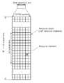
도 3은 하나의 하향링크 슬롯에 대한 자원 그리드(resource grid)를 나타낸 예시도이다.3 is an exemplary diagram illustrating a resource grid for one downlink slot.
FDD 및 TDD 무선 프레임에서 하나의 슬롯은 시간 영역(time domain)에서 복수의 OFDM(orthogonal frequency division multiplexing) 심벌을 포함하고, 주파수 영역에서 다수의 자원블록(resource block, RB)을 포함한다. OFDM 심벌은 3GPP LTE가 하향링크에서 OFDMA를 사용하므로 하나의 심벌 구간(symbol period or symbol time)을 표현하기 위한 것으로, 다중 접속 방식에 따라 SC-FDMA 심벌이라고 할 수 있다. 이하에서 심벌 구간은 하나의 OFDM 심벌 또는 하나의 SC-FDMA 심벌을 의미할 수 있다. 자원 블록은 자원 할당 단위로 하나의 슬롯에서 복수의 연속하는 부반송파(subcarrier)를 포함한다.One slot in the FDD and TDD radio frames includes a plurality of orthogonal frequency division multiplexing (OFDM) symbols in the time domain and includes a plurality of resource blocks (RBs) in the frequency domain. The OFDM symbol is used to represent one symbol period (symbol period or symbol time) since 3GPP LTE uses OFDMA in downlink, and may be referred to as an SC-FDMA symbol according to a multiple access scheme. Hereinafter, the symbol period may mean one OFDM symbol or one SC-FDMA symbol. The resource block includes a plurality of consecutive subcarriers in one slot in resource allocation units.
도 3을 참조하면, 슬롯(예를 들어, 하향링크 서브프레임에 포함된 하향링크 슬롯)은 시간 영역(time domain)에서 복수의 OFDM 심벌을 포함한다. 여기서, 하나의 하향링크 슬롯은 7 OFDM 심벌을 포함하고, 하나의 자원블록은 주파수 영역에서 12 부반송파를 포함하는 것을 예시적으로 기술하나, 이에 제한되는 것은 아니다.Referring to FIG. 3, a slot (eg, a downlink slot included in a downlink subframe) includes a plurality of OFDM symbols in a time domain. Here, one downlink slot includes 7 OFDM symbols and one resource block includes 12 subcarriers in a frequency domain, but is not limited thereto.
자원 그리드 상의 각 요소(element)를 자원요소(resource element)라 하며, 하나의 자원블록(resource block)은 12×7개의 자원요소를 포함한다. 하향링크 슬롯에 포함되는 자원블록의 수 NDL은 셀에서 설정되는 하향링크 전송 대역폭(bandwidth)에 종속한다.Each element on the resource grid is called a resource element, and one resource block includes 12 × 7 resource elements. The number NDL of resource blocks included in the downlink slot depends on the downlink transmission bandwidth set in the cell.
도 4는 하향링크 서브프레임의 구조를 나타낸다.4 shows a structure of a downlink subframe.
도 4를 참조하면, 서브프레임은 2개의 연속적인(consecutive) 슬롯을 포함한다. 서브프레임 내에서 첫 번째 슬롯의 앞선 3 OFDM 심벌들이 PDCCH가 할당되는 제어영역(control region)이고, 나머지 OFDM 심벌들은 PDSCH가 할당되는 데이터영역(data region)이다. 제어영역에는 PDCCH 이외에도 PCFICH, PHICH 등의 제어채널이 할당될 수 있다. 단말은 PDCCH를 통해 전송되는 제어정보를 디코딩하여 PDSCH를 통해 전송되는 데이터 정보를 읽을 수 있다. 여기서, 제어영역이 3 OFDM 심벌을 포함하는 것은 예시에 불과하며, 제어영역에는 2 OFDM 심벌 또는 1 OFDM 심벌이 포함될 수 있다. 서브프레임 내 제어영역이 포함하는 OFDM 심벌의 수는 PCFICH를 통해 알 수 있다.Referring to FIG. 4, a subframe includes two consecutive slots. The first 3 OFDM symbols of the first slot in the subframe are the control region to which the PDCCH is allocated, and the remaining OFDM symbols are the data region to which the PDSCH is allocated. In addition to the PDCCH, the control region may be allocated a control channel such as PCFICH and PHICH. The UE may read the data information transmitted through the PDSCH by decoding the control information transmitted through the PDCCH. Here, the control region includes only 3 OFDM symbols, and the control region may include 2 OFDM symbols or 1 OFDM symbol. The number of OFDM symbols included in the control region in the subframe can be known through the PCFICH.
제어영역은 복수의 CCE(control channel elements)인 논리적인 CCE 열로 구성된다. CCE 열은 하나의 서브프레임 내에서 제어영역을 구성하는 전체 CCE들의 집합이다. CCE는 복수의 자원요소 그룹(resource element group)에 대응된다. 예를 들어, CCE는 9 자원요소 그룹에 대응될 수 있다. 자원요소 그룹은 자원요소로 제어채널을 맵핑하는 것을 정의하기 위해 사용된다. 예를 들어, 하나의 자원요소 그룹은 4개의 자원요소로 구성될 수 있다.The control region is composed of logical CCE columns that are a plurality of CCEs. The CCE column is a collection of all CCEs constituting the control region in one subframe. The CCE corresponds to a plurality of resource element groups. For example, the CCE may correspond to 9 resource element groups. Resource element groups are used to define the mapping of control channels to resource elements. For example, one resource element group may consist of four resource elements.
복수의 PDCCH가 제어영역 내에서 전송될 수 있다. PDCCH는 스케줄링 할당과 같은 제어정보(control information)를 나른다. PDCCH는 하나 또는 몇몇 연속적인 CCE(control channel elements)의 집단(aggregation) 상으로 전송된다. CCE 집단을 구성하는 CCE의 수(Number of CCEs)에 따라 PDCCH의 포맷 및 가능한 PDCCH의 비트 수가 결정된다. PDCCH 전송을 위해 사용되는 CCE의 수를 CCE 집단 레벨(aggregation level)이라 한다. 또한, CCE 집단 레벨은 PDCCH를 검색하기 위한 CCE 단위이다. CCE 집단 레벨의 크기는 인접하는 CCE들의 수로 정의된다. 예를 들어, CCE 집단 레벨은 {1, 2, 4, 8}의 원소일 수 있다.A plurality of PDCCHs may be transmitted in the control region. The PDCCH carries control information such as scheduling assignment. The PDCCH is transmitted on an aggregation of one or several consecutive control channel elements (CCEs). The format of the PDCCH and the number of bits of the PDCCH are determined according to the number of CCEs constituting the CCE group. The number of CCEs used for PDCCH transmission is called a CCE aggregation level. In addition, the CCE aggregation level is a CCE unit for searching for a PDCCH. The size of the CCE aggregation level is defined by the number of adjacent CCEs. For example, the CCE aggregation level may be an element of {1, 2, 4, 8}.
PDCCH를 통해 전송되는 제어정보를 하향링크 제어정보(downlink control information, 이하 DCI)라고 한다. DCI는 상향링크 스케줄링 정보, 하향링크 스케줄링 정보, 시스템 정보(system information), 상향링크 전력 제어 명령(power control command), 페이징을 위한 제어정보, 랜덤 액세스 응답(RACH response)을 지시하기 위한 제어정보 등을 포함한다.Control information transmitted through the PDCCH is referred to as downlink control information (DCI). DCI includes uplink scheduling information, downlink scheduling information, system information, system information, uplink power control command, control information for paging, control information for indicating a random access response, etc. It includes.
DCI 포맷으로는 PUSCH(Physical Uplink Shared Channel) 스케줄링을 위한 포맷 0, 하나의 PDSCH(Physical Downlink Shared channel) 코드워드의 스케줄링을 위한 포맷 1, 하나의 PDSCH 코드워드의 간단한(compact) 스케줄링을 위한 포맷 1A, 공간 다중화 모드에서 단일 코드워드의 랭크-1 전송에 대한 간단한 스케줄링을 위한 포맷 1B, DL-SCH(Downlink Shared Channel)의 매우 간단한 스케줄링을 위한 포맷 1C, 다중 사용자 공간 다중화 모드에서 PDSCH 스케줄링을 위한 포맷 1D, 폐루프(Closed-loop) 공간 다중화 모드에서 PDSCH 스케줄링을 위한 포맷 2, 개루프(Open-loop) 공간 다중화 모드에서 PDSCH 스케줄링을 위한 포맷 2A, PUCCH 및 PUSCH를 위한 2비트 전력 조절의 TPC(Transmission Power Control) 명령의 전송을 위한 포맷 3, 및 PUCCH 및 PUSCH를 위한 1비트 전력 조절의 TPC 명령의 전송을 위한 포맷 3A 등이 있다.The DCI format includes
도 5는 상향링크 서브프레임의 구조를 나타낸다.5 shows a structure of an uplink subframe.
도 5를 참조하면, 상향링크 서브 프레임은 주파수 영역에서 상향링크 제어 정보를 나르는 PUCCH(Physical Uplink Control Channel)가 할당되는 제어영역(region)과 사용자 데이터를 나르는 PUSCH(Physical Uplink Shared Channel)가 할당되는 데이터영역으로 나눌 수 있다.Referring to FIG. 5, the uplink subframe is allocated a control region in which a physical uplink control channel (PUCCH) carrying uplink control information is allocated in a frequency domain and a physical uplink shared channel (PUSCH) carrying user data. It can be divided into data areas.
하나의 단말에 대한 PUCCH는 서브프레임에서 자원블록(RB) 쌍(pair, 51, 52)으로 할당되고, RB 쌍에 속하는 RB들(51,52)은 2개의 슬롯들 각각에서 서로 다른 부반송파를 차지한다. 이를 PUCCH에 할당되는 RB 쌍이 슬롯 경계(slot boundary)에서 주파수 도약(frequency hopping)된다고 한다.The PUCCH for one UE is allocated to a resource block (RB) pair (51, 52) in a subframe, and the RBs 51 and 52 belonging to the RB pair occupy different subcarriers in each of two slots. do. This is said that the RB pair allocated to the PUCCH is frequency hopping at the slot boundary.
PUCCH는 다중 포맷을 지원할 수 있다. 즉, 변조 방식(modualtion scheme)에 따라 서브프레임당 서로 다른 비트 수를 갖는 상향링크 제어 정보를 전송할 수 있다. 예를 들어, BPSK(Binary Phase Shift Keying)을 사용하는 경우(PUCCH 포맷 1a) 1비트의 상향링크 제어 정보를 PUCCH 상으로 전송할 수 있으며, QPSK(Quadrature Phase Shift Keying)을 사용하는 경우(PUCCH 포맷 1b) 2비트의 상향링크 제어 정보를 PUCCH 상으로 전송할 수 있다. PUCCH 포맷은 이외에도 포맷 1, 포맷 2, 포맷 2a, 포맷 2b 등이 있다(이는 3GPP TS 36.211 V8.2.0 (2008-03) "Technical Specification Group Radio Access Network; Evolved Universal Terrestrial Radio Access (E-UTRA); Physical Channels and Modulation (Release 8)"의 5.4절을 참조할 수 있다).PUCCH may support multiple formats. That is, uplink control information having different numbers of bits per subframe may be transmitted according to a modulation scheme. For example, when using Binary Phase Shift Keying (BPSK) (PUCCH format 1a), uplink control information of 1 bit may be transmitted on PUCCH, and when using Quadrature Phase Shift Keying (QPSK) (PUCCH format 1b). 2 bits of uplink control information can be transmitted on the PUCCH. In addition to the PUCCH format, there are
도 6은 중계국이 수행할 수 있는 동작과 제한 요건을 나타낸다.6 illustrates the operations and limitation requirements that a relay station may perform.
중계국은 기지국과의 관계에서 백홀 상향링크 전송(B-UL Tx), 백홀 하향링크 수신(B-DL Rx)을 수행할 수 있다. 기지국은 중계국과의 관계에서 백홀 하향링크 전송(B-DL Tx), 백홀 상향링크 수신(B-UL Tx)을 수행할 수 있다.The RS may perform backhaul uplink transmission (B-UL Tx) and backhaul downlink reception (B-DL Rx) in relation to the base station. The base station may perform backhaul downlink transmission (B-DL Tx) and backhaul uplink reception (B-UL Tx) in relation to the relay station.
중계국은 중계국 단말과의 관계에서 액세스 하향링크 전송(A-DL Tx), 액세스 상향링크 수신(A-UL Rx)을 수행할 수 있다. 중계국 단말은 중계국과의 관계에서 액세스 상향링크 전송(A-UL Tx), 액세스 하향링크 수신(A-DL Rx)을 수행할 수 있다.The RS may perform an access downlink transmission (A-DL Tx) and an access uplink reception (A-UL Rx) in a relationship with the RS. The RS may perform access uplink transmission (A-UL Tx) and access downlink reception (A-DL Rx) in relation to the relay station.
도면 6에는 도시하지 않았지만, 기지국은 매크로 단말과의 관계에서 매크로 하향링크 전송(M-DL Tx), 매크로 상향링크 수신(M-UL Rx)을 수행할 수 있다.Although not shown in FIG. 6, the base station may perform macro downlink transmission (M-DL Tx) and macro uplink reception (M-UL Rx) in relation to the macro terminal.
일반적으로 중계국은 자기 간섭(self interference)으로 인해 동일 주파수 대역에서 동시에 신호를 전송하거나 수신할 수 없다. 즉, 중계국은 백홀 하향링크 수신(B-DL Rx)과 액세스 하향링크 전송(A-DL Tx)을 동시에 수행할 수 없다. 또한, 중계국은 백홀 상향링크 전송(B-UL Tx)과 액세스 상향링크 수신(A-UL Rx)을 동시에 수행할 수 없다. 따라서, 동일한 주파수 대역에서 신호의 전송, 수신은 서로 다른 서브프레임에서 수행된다.In general, relay stations cannot transmit or receive signals simultaneously in the same frequency band due to self interference. That is, the RS cannot simultaneously perform backhaul downlink reception (B-DL Rx) and access downlink transmission (A-DL Tx). In addition, the RS cannot simultaneously perform backhaul uplink transmission (B-UL Tx) and access uplink reception (A-UL Rx). Therefore, transmission and reception of signals in the same frequency band are performed in different subframes.
또한, 일반적으로 중계국은 백홀 하향링크 수신(B-DL Rx) 및 액세스 하향링크 전송(A-DL Tx)의 스위칭 시 보호 구간(guard time, 또는 guard period)이 필요하다. 마찬가지로 백홀 상향링크 전송(B-UL Tx)과 액세스 상향링크 수신(A-UL Rx) 간의 스위칭 시에 보호 구간이 필요하다. 중계국에서 사용되는 아날로그 증폭기(analog amplifier)의 천이 시간(transient time) 특성을 고려할 때 보호 구간은 대략 20 마이크로 초(μs) 정도일 수 있다.In addition, in general, the relay station needs a guard time or guard period in switching backhaul downlink reception (B-DL Rx) and access downlink transmission (A-DL Tx). Similarly, a guard interval is required when switching between backhaul uplink transmission (B-UL Tx) and access uplink reception (A-UL Rx). Considering the transient time characteristic of the analog amplifier used in the relay station, the guard interval may be about 20 microseconds (μs).
도 7 및 도 8은 서브프레임 내에서 보호 구간이 배치되는 예를 나타낸다.7 and 8 illustrate an example in which a guard interval is arranged in a subframe.
보호 구간은 1 심벌(예를 들어 1 OFDM 심벌 또는 1 SC-FDMA 심벌)보다 작은 시간 구간일 수 있다. 즉, 보호 구간은 시간 측면에서 1 심벌의 일 부분일 수 있다. 보호 구간의 위치 및 시간 구간의 크기는 백홀 서브프레임의 구조와 액세스 서브프레임간의 타이밍 관계에 따라 다양하게 변경될 수 있다. 예를 들어, 보호 구간 중 어느 하나가 도 7과 같이 서브프레임의 가운데 심벌에 위치할 수도 있고, 도 8과 같이 각 보호 구간이 서브프레임의 첫번째 및 마지막 심벌에 위치할 수도 있다. 3GPP LTE에서는 스케줄링의 최소 단위가 서브프레임이다. 따라서, 중계국은 백홀 링크와 액세스 링크에서 전송/수신 스위칭을 수행하는 경우 서브프레임 단위로 이러한 스위칭을 수행하게 된다. 이 때, 보호 구간은 도 8과 같이 서브프레임의 첫번째 심벌 및 마지막 심벌에 위치하게 된다. 하나의 심벌 내에 보호 구간이 위치하게 되면 보호 구간이 1 심벌보다 작은 시간 구간을 차지하더라도 해당 심벌을 사용할 수 없게 될 수 있다(도 7 및 도 8에서 사용할 수 없는 심벌의 일 부분을 ‘N’으로 나타내고 있다). 즉, 보호 구간을 포함하는 심벌은 낭비된다.The guard interval may be a time interval smaller than one symbol (for example, one OFDM symbol or one SC-FDMA symbol). That is, the guard interval may be a part of one symbol in time. The location of the guard interval and the size of the time interval may be variously changed according to the timing relationship between the structure of the backhaul subframe and the access subframe. For example, one of the guard periods may be located in the center symbol of the subframe as shown in FIG. 7, and each guard period may be located in the first and last symbols of the subframe as shown in FIG. 8. In 3GPP LTE, the minimum unit of scheduling is a subframe. Accordingly, the relay station performs such switching on a subframe basis when performing transmission / reception switching on the backhaul link and the access link. At this time, the guard period is located in the first symbol and the last symbol of the subframe, as shown in FIG. If the guard interval is located within one symbol, even if the guard interval occupies a time interval smaller than 1 symbol, the corresponding symbol may not be used (a portion of the symbol that is not usable in FIGS. 7 and 8 is referred to as 'N'). Is shown). That is, the symbol including the guard interval is wasted.
또한, 3GPP LTE에서는 서브프레임의 마지막 심벌에서 상향링크 스케줄링을 위한 SRS(sounding reference signal)를 전송한다. 상술한 바와 같이 보호 구간으로 인해 서브프레임의 마지막 심벌을 사용할 수 없다면, 중계국은 SRS를 전송하기 어렵다.In addition, 3GPP LTE transmits a sounding reference signal (SRS) for uplink scheduling in the last symbol of a subframe. As described above, if the last symbol of the subframe cannot be used due to the guard period, the RS is difficult to transmit the SRS.
이러한 문제점을 해결하기 위한 한가지 방법은 새로운 심벌을 정의하는 방법이다. 즉, 종래의 심벌 예컨대, OFDM 심벌 또는 SC-FDMA 심벌보다 작은 시간 구간을 가지는 심벌을 정의하는 것이다. 이러한 새로운 심벌을 보호 구간에 의해 낭비되는 시간 구간에 적용하여 무선자원의 낭비를 방지할 수 있다.One way to solve this problem is to define a new symbol. That is, a symbol having a time interval smaller than a conventional symbol, for example, an OFDM symbol or an SC-FDMA symbol is defined. This new symbol may be applied to the time interval wasted by the guard interval to prevent waste of radio resources.
상기 문제점을 해결하기 위한 다른 방법은 기지국, 중계국 및 단말 간의 신호 전송/수신 서브프레임을 오프셋 시간 또는/및 추가적 정렬 정보를 통해 쉬프트 시킴으로써 해결하는 것이다.Another method for solving the problem is to solve the signal transmission / reception subframe between the base station, relay station and the terminal by shifting the offset time and / or additional alignment information.
먼저 발명을 명확하게 하기 위해 용어를 정의한다.First, terms are defined to clarify the invention.
도 9는 전달 지연 시간 및 오프셋 시간을 나타낸다.9 shows the propagation delay time and offset time.
도 9 (a)를 참조하면, 기지국이 백홀 하향링크 전송(B-DL Tx)을 수행한다. 이러한 경우, 중계국이 백홀 하향링크 수신(B-DL Rx)을 수행하는 것은 전달 지연 시간(propagation delay time, Tp) 후이다. 즉, 전달 지연 시간은 소스국에서 신호를 전송하는 시간과 목적국이 신호를 수신하는 시간에 있어, 물리적 신호 전송으로 인해 발생하는 지연시간이다. 오프셋 시간(offset time, To)은 중계국의 백홀 링크 서브프레임과 액세스 링크 서브프레임 간의 의도적인 오프셋을 의미한다. 도 9 (a)에서 중계국의 백홀 하향링크 수신(B-DL Rx)과 액세스 하향링크 전송(A-DL Tx)는 오프셋 시간(To)을 가지고 수행될 수 있다. 상술한 전달 지연 시간 및/또는 오프셋 시간은 기지국에 의해 중계국 및 단말에게 전송될 수 있다. 기지국은 P-BCH의 동기화 신호를 통해 오프셋 시간을 전송할 수도 있고, 물리적 채널 예를 들면 PDCCH를 통해 오프셋 시간을 전송할 수도 있다. 중계국 또는 단말은 기지국으로부터 오프셋 시간을 수신하면 그에 따른 타이밍에 의해 신호를 전송 또는 수신한다.Referring to FIG. 9 (a), the base station performs backhaul downlink transmission (B-DL Tx). In this case, it is after the propagation delay time Tp that the relay station performs the backhaul downlink reception (B-DL Rx). That is, the propagation delay time is a delay time caused by the physical signal transmission in the time of transmitting a signal from the source station and the time of receiving the signal from the target station. The offset time (To) means an intentional offset between the backhaul link subframe and the access link subframe of the relay station. In FIG. 9 (a), the backhaul downlink reception (B-DL Rx) and the access downlink transmission (A-DL Tx) of the relay station may be performed with an offset time (To). The above-described propagation delay time and / or offset time may be transmitted by the base station to the relay station and the terminal. The base station may transmit an offset time through a synchronization signal of the P-BCH, or may transmit an offset time through a physical channel, for example, a PDCCH. When the RS or the terminal receives the offset time from the BS, the RS transmits or receives a signal by timing.
도 9(b)는 도 9(a)의 전달 지연 시간을 제외하고 나타낸 것이다. 전달 지연 시간을 제외하면 도 9(a)는 도 9(b)와 같이 간단히 표시할 수 있다. 이하의 설명 및 도면에서 필요에 따라 전달 지연 시간을 제외하고 기지국, 중계국 및 단말 간의 신호 전송/수신에 대한 시간관계를 표시하기도 한다.Figure 9 (b) is shown except for the propagation delay time of Figure 9 (a). Except for the propagation delay time, FIG. 9 (a) may be simply displayed as shown in FIG. 9 (b). In the following description and drawings, a time relationship for signal transmission / reception between a base station, a relay station, and a terminal may be indicated as necessary except for a propagation delay time.
도 10 내지 도 14는 중계국이 기지국으로부터 백홀 하향링크 신호를 수신하는 서브프레임과 중계국이 중계국 단말에게 액세스 하향링크 신호를 전송하는 서브프레임 간의 시간 관계를 매크로 서브프레임을 기준으로 나타낸 예들이다. 이 때 전달 지연 시간을 고려하여 나타내고 있다.10 to 14 illustrate examples of a time relationship between a subframe in which a relay station receives a backhaul downlink signal from a base station and a subframe in which the relay station transmits an access downlink signal to a relay terminal, based on a macro subframe. In this case, the transfer delay time is considered.
도 10은 기지국의 매크로 서브프레임과 중계국의 B-DL Rx 서브프레임 및 A-DL Tx 서브프레임과의 시간 관계를 나타낸다.10 shows a time relationship between a macro subframe of a base station and a B-DL Rx subframe and an A-DL Tx subframe of a relay station.
도 10을 참조하면, 매크로 서브프레임과 B-DL Tx 서브프레임은 정렬되어 있다. B-DL Rx 서브프레임은 전달 지연 시간(Tp)을 고려하여 B-DL Tx 서브프레임과 비교하여 Tp만큼 시간적으로 뒤에 위치한다. A-DL Tx 서브프레임은 B-DL Rx 서브프레임에서 고정된 오프셋 시간(offset time, To) 만큼 쉬프트되어 위치한다. 중계국에서의 스위칭 시간이 싸이클릭 프리픽스(cyclic prefix)보다 긴 경우이다.Referring to FIG. 10, the macro subframe and the B-DL Tx subframe are aligned. The B-DL Rx subframe is located later in time by Tp compared to the B-DL Tx subframe in consideration of the propagation delay time Tp. The A-DL Tx subframe is shifted and positioned by a fixed offset time (To) in the B-DL Rx subframe. The switching time at the relay station is longer than the cyclic prefix.
이러한 시간 관계에서 중계국이 K개의 심벌을 사용하여 중계국 단말에게 제어 신호를 전송한다고 가정하자. 예를 들어, 중계국이 중계국 단말에게 제어 신호를 전송하는 R-PDCCH에 사용되는 심벌의 개수가 K개라고 가정하자(이하 모두 동일). 그러면, 중계국은 심벌 인덱스 M = K+1에서부터 서브프레임의 마지막 심벌 인덱스까지의 심벌에서 백홀 하향링크 신호를 수신할 수 있다. 예를 들어, 중계국이 전송하는 R-PDCCH에 사용하는 심벌의 개수가 2개라고 가정하면, 중계국은 심벌 인덱스 3인 심벌부터 서브프레임의 마지막 심벌인 심벌 인덱스 13까지의 심벌을 이용하여 백홀 하향링크 신호를 수신할 수 있다. 중계국은 심벌 인덱스가 3인 심벌과 심벌 인덱스가 13인 심벌을 사용할 수 있으므로 백홀 링크의 가용 무선자원이 증가하는 효과가 있다.In this time relationship, suppose that the relay station transmits a control signal to the relay station using K symbols. For example, suppose that the number of symbols used for the R-PDCCH for transmitting a control signal to the RS by the RS is K (hereinafter, all the same). Then, the RS may receive a backhaul downlink signal in symbols from symbol index M = K + 1 to the last symbol index of the subframe. For example, assuming that the number of symbols used for the R-PDCCH transmitted by the relay station is 2, the relay station uses a symbol from
도 11은 기지국의 매크로 서브프레임과 B-DL Tx 서브프레임, 중계국의 B-DL Rx 서브프레임 및 A-DL Tx 서브프레임과의 시간 관계를 나타내는 다른 예이다.11 is another example illustrating a time relationship between a macro subframe of a base station and a B-DL Tx subframe, a B-DL Rx subframe and an A-DL Tx subframe of a relay station.
이러한 시간 관계는 중계국의 스위칭 시간이 매우 짧은 경우(예를 들어 싸이클릭 프리픽스보다 짧은 경우)이고, B-DL Rx 서브프레임과 A-DL Tx 서브프레임이 정렬되어 있는 경우이다. 중계국에서 사용하는 아날로그 증폭기의 성능에 따라 스위칭 시간이 매우 짧을 수 있다. 이 때, 보호 구간은 B-DL Rx 서브프레임의 심벌 인덱스 2인 심벌의 앞, 심벌 인덱스 13인 심벌의 뒤에 위치하게 된다. 보호 구간의 시간 구간이 싸이클릭 프리픽스보다 짧기 때문에 심벌간의 동기화(synchronization)에 영향을 미치지 않는다고 볼 수 있다.This time relationship is when the switching time of the relay station is very short (for example, shorter than the cyclic prefix), and when the B-DL Rx subframe and the A-DL Tx subframe are aligned. Depending on the performance of the analog amplifier used in the relay station, the switching time can be very short. In this case, the guard period is located in front of the symbol having the
이러한 시간 관계에서 중계국은 심벌 인덱스 M = K 부터 서브프레임의 마지막 심벌 인덱스까지의 심벌에서 백홀 하향링크 신호를 수신할 수 있다. 즉, 도 10과와 비교하여 백홀 하향링크 신호를 수신할 수 있는 심벌 인덱스가 K부터 시작된다는 점에서 차이가 있다.In this time relationship, the RS may receive a backhaul downlink signal in symbols from symbol index M = K to the last symbol index of the subframe. That is, compared with FIG. 10, the symbol index for receiving the backhaul downlink signal starts from K.
도 12 내지 도 14는 기지국의 매크로 서브프레임 및 B-DL Tx 서브프레임, 중계국의 B-DL Rx 서브프레임 및 A-DL Tx 서브프레임과의 시간 관계를 나타내는 또 다른 예들이다.12 to 14 are still other examples illustrating the time relationship between the macro subframe and the B-DL Tx subframe of the base station, the B-DL Rx subframe and the A-DL Tx subframe of the relay station.
도 12를 참조하면, 기지국의 B-DL Tx 서브프레임과 중계국의 A-DL Tx 서브프레임이 동일한 시간에 시작된다(즉, 동기화되어 있다). B-DL Rx 서브프레임은 B-DL Tx 서브프레임에 비해 전달 지연 시간만큼 뒤로 쉬프트될 수 있다. 이러한 시간 관계는 전달 지연 시간 Tp 가 하나의 심벌 구간 L 보다 짧고, 전달 지연 시간 Tp 가 보호 구간 G1 보다 짧으며 (Tp + 보호 구간 G2)가 심벌 구간 L 보다 짧은 경우이다. 이것은 [(Tp < L) & (Tp < G1) & (Tp + G2 < L), 심벌 구간 = L]과 같이 표현할 수 있다.Referring to FIG. 12, the B-DL Tx subframe of the base station and the A-DL Tx subframe of the relay station start at the same time (ie, synchronized). The B-DL Rx subframe may be shifted backward by the propagation delay time compared to the B-DL Tx subframe. This time relationship is a case where the propagation delay time Tp is shorter than one symbol period L, the propagation delay time Tp is shorter than the guard period G1 and (Tp + guard period G2) is shorter than the symbol period L. This can be expressed as [(Tp <L) & (Tp <G1) & (Tp + G2 <L), symbol interval = L].
중계국은 심벌 인덱스 M이 K 이상인 심벌에서 심벌 인덱스가 n인 심벌까지 백홀 하향링크 신호를 수신할 수 있다. 상기 심벌 인덱스 n은 전달 지연 시간 Tp 및 스위칭 시간에 따른 보호 구간의 크기에 따라 달라질 수 있다. 예를 들어, K=2인 경우, 도 12에서는 중계국이 심벌 인덱스 M = 3부터 12까지의 심벌을 이용하여 백홀 하향링크 신호를 수신할 수 있다.The RS may receive a backhaul downlink signal from a symbol having a symbol index M of K or more to a symbol having a symbol index of n. The symbol index n may vary depending on the size of the guard period according to the propagation delay time Tp and the switching time. For example, when K = 2, in FIG. 12, the RS may receive a backhaul downlink signal using symbols from symbol indexes M = 3 to 12.
도 13은 보호 구간 G1이 전달 지연 시간 Tp보다 작고, Tp 는 심벌 구간 L 보다 작으며, Tp와 보호 구간 G2의 합이 심벌 구간 L 보다 작은 경우이다. 즉, [( G1 < Tp < L) & (Tp + G2 < L), 심벌 구간 = L ]이다. 이러한 경우 중계국은 심벌 인덱스 M = 2부터 12까지의 심벌을 이용하여 백홀 하향링크 신호를 수신할 수 있다. 즉, 중계국은 11개의 심벌을 백홀 하향링크 수신에 사용할 수 있다.13 is a case where the guard interval G1 is smaller than the propagation delay time Tp, Tp is smaller than the symbol interval L, and the sum of Tp and the guard interval G2 is smaller than the symbol interval L. That is, [(G1 <Tp <L) & (Tp + G2 <L), symbol interval = L]. In this case, the RS may receive a backhaul downlink signal using symbols from symbol index M = 2 to 12. That is, the RS can use 11 symbols for backhaul downlink reception.
도 14는 보호 구간 G1이 전달 지연 시간 Tp보다 작고, Tp 는 심벌 구간 L 보다 작으며, Tp 와 보호 구간 G2의 합이 심벌 구간 L 보다 큰 경우이다. 즉, [(G1 < Tp < L) & (Tp + G2 > L), 심벌 구간 = L]이다. 이러한 경우, 중계국은 심벌 인덱스 M = 2부터 11까지의 심벌을 이용하여 백홀 하향링크 신호를 수신할 수 있다. 즉, 중계국은 10개의 심벌을 백홀 하향링크 수신에 사용할 수 있다.14 shows a case in which the guard interval G1 is smaller than the propagation delay time Tp, Tp is smaller than the symbol interval L, and the sum of Tp and the guard interval G2 is larger than the symbol interval L. That is, [(G1 <Tp <L) & (Tp + G2> L), symbol interval = L]. In this case, the RS may receive a backhaul downlink signal using symbols from symbol index M = 2 to 11. That is, the RS may use 10 symbols for backhaul downlink reception.
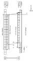
도 15 내지 도 21은 중계국이 기지국으로 백홀 상향링크 신호를 전송하는 B-UL Tx 서브프레임과 중계국이 중계국 단말으로부터 액세스 상향링크 신호를 수신하는 A-UL Rx 서브프레임 간의 시간 관계를 기지국의 매크로 서브프레임을 기준으로 나타낸 예들이다. 이 때, 전달 지연 시간을 고려하여 나타내고 있다.15 to 21 illustrate a time relationship between a B-UL Tx subframe in which a relay station transmits a backhaul uplink signal to a base station and an A-UL Rx subframe in which the relay station receives an access uplink signal from a relay station terminal. Examples are shown based on the frame. At this time, the transfer delay time is considered.
도 15는 B-UL Tx 서브프레임과 A-UL Rx 서브프레임이 고정된 오프셋 값으로 시차를 두고 있다. 도 15에서는 오프셋 시간(To)이 음의 값인 경우를 예시하고 있다. 중계국은 SC-FDMA 심벌 인덱스가 0인 심벌은 천공하고, SC-FDMA 심벌 인덱스가 1인 심벌부터 13인 심벌까지 13개의 심벌을 사용하여 백홀 상향링크 신호를 전송할 수 있다(노멀 CP의 경우). 즉, 중계국이 백홀 상향링크 신호를 전송하는 B-UL Tx 서브프레임과 중계국 단말로부터 액세스 상향링크 신호를 수신하는 A-UL Rx 서브프레임 간에 오프셋 시간을 주어 중계국이 13개의 심벌을 백홀 상향링크 신호 전송에 사용할 수 있게 하는 것이다.FIG. 15 shows a time offset between fixed B-UL Tx subframes and A-UL Rx subframes. 15 illustrates a case where the offset time To is a negative value. The RS may puncture a symbol having an SC-FDMA symbol index of 0 and transmit a backhaul uplink signal using 13 symbols from a symbol having a SC-FDMA symbol index of 1 to a symbol having 13 (in the case of a normal CP). That is, the RS gives an offset time between the B-UL Tx subframe that transmits the backhaul uplink signal and the A-UL Rx subframe that receives the access uplink signal from the RS, and the RS transmits 13 symbols of the backhaul uplink signal. To make it available.
도 16은 중계국의 B-UL Tx 서브프레임과 A-UL Rx 서브프레임 사이에 시차를 두지 않고 있다. 즉, 오프셋 값이 없다. 이러한 시간 관계는 중계국의 B-UL Tx 서브프레임과 A-UL Rx 서브프레임이 정렬되어 있고 중계국의 스위칭 시간이 매우 짧은 경우(예를 들면 싸이클릭 프리픽스보다 짧은 경우)이다. 중계국의 스위칭 시간이 매우 짧은 경우에는 보호 구간이 매우 짧아도 무방하다. 따라서, 중계국의 백홀 상향링크 전송과 액세스 상향링크 수신의 스위칭에 필요한 보호 구간이 서브프레임 구조에 거의 영향을 미치지 않는다. 중계국은 SC-FDMA 심벌 인덱스가 0인 심벌부터 13인 심벌까지 14개의 심벌을 사용하여 백홀 상향링크 신호를 전송할 수 있다.16 shows no time difference between the B-UL Tx subframe and the A-UL Rx subframe of the relay station. That is, there is no offset value. This time relationship is when the B-UL Tx subframe and the A-UL Rx subframe of the relay station are aligned and the switching time of the relay station is very short (e.g., shorter than the cyclic prefix). If the switching time of the relay station is very short, the guard interval may be very short. Therefore, the guard period required for switching the backhaul uplink transmission and the access uplink reception of the RS has little effect on the subframe structure. The RS may transmit the backhaul uplink signal using 14 symbols ranging from
도 17은 중계국의 B-UL Tx 서브프레임과 A-UL Rx 서브프레임이 고정된 오프셋 값으로 시차를 두고 있다. 오프셋 시간이 음의 값을 가지는 경우를 예시하고 있다. 도 16과 비교하여 차이점은 중계국의 A-UL Rx 서브프레임과 B-UL Tx 서브프레임 사이에 필요한 보호 구간이 A-UL Rx 서브프레임에 위치하는 점이다. 따라서, 중계국은 SC-FDMA 심벌 인덱스가 0인 심벌부터 13인 심벌까지 14개의 심벌 모두를 사용하여 백홀 상향링크 신호를 전송할 수 있다(노멀 CP의 경우). 반면 A-UL Rx 서브프레임의 마지막 심벌에 보호 구간이 위치하므로 중계국 단말은 상기 마지막 심벌에서 SRS를 전송하기 어려울 수 있다. 중계국이 이러한 SRS를 수신하기 어렵기 때문이다.In FIG. 17, a B-UL Tx subframe and an A-UL Rx subframe of a relay station are staggered with a fixed offset value. The case where the offset time has a negative value is illustrated. Compared with FIG. 16, the difference is that the guard period required between the A-UL Rx subframe and the B-UL Tx subframe of the relay station is located in the A-UL Rx subframe. Accordingly, the RS can transmit the backhaul uplink signal using all 14 symbols from the symbol having the SC-FDMA symbol index of 0 to the symbol having 13 (in the case of normal CP). On the other hand, since the guard period is located in the last symbol of the A-UL Rx subframe, it may be difficult for the RS to transmit the SRS in the last symbol. This is because the relay station is difficult to receive such an SRS.
도 18은 중계국의 B-UL Tx 서브프레임과 A-UL Rx 서브프레임이 고정된 오프셋 값으로 시차를 두고 있다. 도 17과의 차이는 오프셋 시간이 양의 값을 가지는 경우를 예시한다는 점이다. 즉, A-UL Rx 서브프레임이 B-UL Tx 서브프레임보다 오프셋 시간만큼 시간적으로 앞서게 된다. 이러한 시간 관계에서 중계국은 SC-FDMA 심벌 인덱스가 0인 심벌부터 12인 심벌까지 13개의 심벌을 사용하여 백홀 상향링크 신호를 전송할 수 있다(노멀 CP의 경우). B-UL Tx 서브프레임의 마지막 심벌 즉 심벌 인덱스가 13인 심벌은 보호 구간으로 인해 사용할 수 없다.18 shows a time offset with a fixed offset value between a B-UL Tx subframe and an A-UL Rx subframe of a relay station. The difference from FIG. 17 is that it illustrates the case where the offset time has a positive value. That is, the A-UL Rx subframe is temporally advanced by the offset time than the B-UL Tx subframe. In such a time relationship, the RS may transmit a backhaul uplink signal using 13 symbols from a symbol having a SC-FDMA symbol index of 0 to a symbol having 12 (in the case of a normal CP). The last symbol of the B-UL Tx subframe, that is, the symbol having a symbol index of 13, cannot be used due to the guard period.
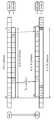
도 19는 중계국의 A-UL Rx 서브프레임과 기지국의 B-UL Rx 서브프레임이 정렬되어 있고, B-UL Tx 서브프레임이 전달 지연 시간을 고려하여 배치된다. 이러한 시간 관계는 전달 지연 시간 Tp 와 보호 구간 G1의 합이 하나의 심벌 구간 L 보다 작고, 전달 지연 시간 Tp 가 보호 구간 G1 보다 작으며, 전달 지연 시간 Tp 와 심벌 구간 L의 합이 보호 구간 G2보다 큰 경우에 적용될 수 있다. 즉, [ (Tp + G1 < L) & (Tp < G1) & (Tp + L > G2), 심벌 구간 = L ]인 경우에 적용할 수 있다.In FIG. 19, the A-UL Rx subframe of the relay station and the B-UL Rx subframe of the base station are aligned, and the B-UL Tx subframe is arranged in consideration of the propagation delay time. This time relationship is such that the sum of propagation delay time Tp and guard interval G1 is smaller than one symbol interval L, the propagation delay time Tp is smaller than guard interval G1, and the sum of propagation delay time Tp and symbol interval L is greater than guard interval G2. It can be applied in large cases. That is, it is applicable to the case of [(Tp + G1 <L) & (Tp <G1) & (Tp + L> G2), symbol interval = L].
중계국은 B-UL Tx 서브프레임에서 심벌 인덱스 N이 1보다 큰 심벌에서 심벌 인덱스 N이 12인 심벌까지의 구간을 이용하여 백홀 상향링크 신호를 전송할 수 있다(노멀 CP의 경우). 즉, 12개의 심벌을 사용하여 백홀 상향링크 신호를 전송할 수 있다.The RS may transmit a backhaul uplink signal using a period from a symbol having a symbol index N greater than 1 to a symbol having a symbol index N of 12 in a B-UL Tx subframe (in the case of a normal CP). That is, the backhaul uplink signal may be transmitted using 12 symbols.
도 20은 도 19와 마찬가지로 중계국의 A-UL Rx 서브프레임과 기지국의 B-UL Rx 서브프레임이 정렬되어 있고, B-UL Tx 서브프레임이 전달 지연 시간을 고려하여 배치된다. 도 19와의 차이는 적용 요건의 차이이다. 도 20과 같은 시간 관계는 전달 지연 시간 Tp 와 보호 구간 G1의 합이 하나의 심벌 구간 L보다 작고, 보호 구간 G2가 전달 지연 시간 Tp 보다 작고 전달 지연 시간 Tp 는 심벌 구간 L 보다 작은 경우에 이러한 시간 관계가 적용될 수 있다. 즉, [(Tp + G1) < L & (G2 < Tp < L), 심벌 구간 = L ]인 경우에 적용될 수 있다. 중계국은 심벌 인덱스 N이 1인 심벌부터 13인 심벌까지의 구간을 이용하여 백홀 상향링크 신호를 전송할 수 있다(노멀 CP의 경우). 즉, 13개의 심벌을 사용하여 백홀 상향링크 신호를 전송할 수 있다.In FIG. 20, as in FIG. 19, the A-UL Rx subframe of the RS and the B-UL Rx subframe of the BS are aligned, and the B-UL Tx subframe is arranged in consideration of a propagation delay time. The difference from FIG. 19 is the difference in application requirements. The time relationship as shown in FIG. 20 is such that the sum of the propagation delay time Tp and the guard interval G1 is smaller than one symbol interval L, the guard interval G2 is smaller than the propagation delay time Tp and the propagation delay time Tp is smaller than the symbol interval L. Relationships may apply. That is, it can be applied to the case of [(Tp + G1) <L & (G2 <Tp <L), symbol interval = L]. The RS may transmit a backhaul uplink signal using a period from a symbol having a symbol index N of 1 to a symbol having 13 (in the case of a normal CP). That is, the backhaul uplink signal may be transmitted using 13 symbols.
도 21은 도 20과 마찬가지로 중계국의 A-UL Rx 서브프레임과 기지국의 B-UL Rx 서브프레임이 정렬되어 있고, B-UL Tx 서브프레임이 전달 지연 시간을 고려하여 배치된다. 도 21의 시간 관계가 적용되는 적용 요건은 전달 지연 시간 Tp 와 보호 구간 G1의 합이 하나의 심벌 구간 L 보다 작고, 보호 구간 G2가 전달 지연 시간 Tp 보다 작으며 전달 지연 시간 Tp 는 심벌 구간 L 보다 작은 경우이다. 즉, [(Tp + G1 > L) & (G2 < Tp < L), 심벌 구간 = L]이다. 중계국은 심벌 인덱스 N이 2인 심벌부터 13인 심벌까지 12개의 심벌을 이용하여 백홀 상향링크 신호를 전송할 수 있다(노멀 CP의 경우).In FIG. 21, as in FIG. 20, the A-UL Rx subframe of the RS and the B-UL Rx subframe of the BS are aligned, and the B-UL Tx subframe is arranged in consideration of a propagation delay time. Application requirements to which the time relationship of FIG. 21 applies are that the sum of the propagation delay time Tp and the guard interval G1 is smaller than one symbol interval L, the guard interval G2 is smaller than the propagation delay time Tp and the propagation delay time Tp is greater than the symbol interval L. Small case. That is, [(Tp + G1> L) & (G2 <Tp <L), symbol interval = L]. The RS may transmit a backhaul uplink signal using 12 symbols ranging from a symbol having a symbol index N of 2 to a symbol having 13 (in the case of a normal CP).
이제 기지국, 중계국 및 중계국 단말을 포함하는 무선통신 시스템에서 각 장치가 어떠한 시간 관계를 가지고 동작하는지 설명한다.Now, a description will be given of what time relationship each device operates in a wireless communication system including a base station, a relay station, and a relay station terminal.
도 22는 기지국, 중계국 및 중계국 단말을 포함하는 무선통신 시스템에서 시간관계를 나타내는 일 예이다. 도 22에서는 전달 지연 시간은 나타내지 않았다.22 is an example illustrating a time relationship in a wireless communication system including a base station, a relay station, and a relay station terminal. In Fig. 22, the propagation delay time is not shown.
도 22를 참조하면, 기지국(eNB)과 중계국(RN) 또는 기지국(eNB)과 중계국 단말(UE) 간에 서브프레임의 시작 위치가 동기화되어 있다. 서브프레임 #(n+1)에서 중계국은 중계국 단말이 전송하는 액세스 상향링크 신호를 수신(A-UL Rx)하고, 서브프레임 #(n+2)에서 백홀 상향링크 신호로 전송(B-UL Tx)한다. 도 22에서 나타난 바와 같이 서브프레임 #(n+2) 또는 서브프레임 #n에서의 백홀 상향링크 신호 전송(B-UL Tx) 시에 서브프레임 내에 보호 구간이 위치하게 되므로 서브프레임 전체에 걸쳐 백홀 상향링크 신호를 전송할 수 없다. 중계국은 축소 포맷 즉, 서브프레임에 포함된 14개의 심벌 중 첫번째 심벌 및 마지막 심벌을 천공하고 12개의 심벌만을 사용하여 백홀 상향링크 신호를 전송하게 된다. 축소 포맷을 이용하여 백홀 상향링크 신호를 전송하는 경우, 중계국은 백홀 SRS(S’으로 표시)을 전송하고자 하면 특수한 형태의 SRS를 전송하여야 한다. 즉, 1 심벌보다 작은 구간에 대해 정의된 특수한 형태의 SRS를 생성하여 서브프레임의 마지막 심벌에서 백홀 SRS로 전송하는 것이다.Referring to FIG. 22, a start position of a subframe is synchronized between a base station eNB and a relay station RN or a base station eNB and a relay station UE. In subframe # (n + 1), the relay station receives an access uplink signal transmitted from the relay station terminal (A-UL Rx) and transmits as a backhaul uplink signal in subframe # (n + 2) (B-UL Tx )do. As shown in FIG. 22, since a guard period is located in a subframe during a backhaul uplink signal transmission (B-UL Tx) in subframe # (n + 2) or subframe #n, the backhaul uplink is performed throughout the entire subframe. The link signal cannot be transmitted. The RS punctures the first and last symbols of the 14 symbols included in the reduced format, that is, the subframe, and transmits the backhaul uplink signal using only 12 symbols. When transmitting a backhaul uplink signal using a reduced format, the relay station should transmit a special type of SRS if it wants to transmit a backhaul SRS (denoted by S '). That is, a special type of SRS defined for a section smaller than 1 symbol is generated and transmitted to the backhaul SRS in the last symbol of the subframe.
도 23은 기지국, 중계국 및 중계국 단말을 포함하는 무선통신 시스템에서 시간관계를 나타내는 다른 예이다. 도 23에서는 전달 지연 시간은 나타내지 않았다.23 is another example illustrating a time relationship in a wireless communication system including a base station, a relay station, and a relay station terminal. In FIG. 23, the propagation delay time is not shown.
도 23을 참조하면, 기지국과 중계국 간의 서브프레임들의 시간 관계와 중계국과 중계국 단말 간의 서브프레임들의 시간 관계에 있어 고정된 시간만큼 오프셋이 존재한다. 서브프레임 #(n+1)에서 중계국의 A-DL Tx 서브프레임 및 A-UL Rx서브프레임, 중계국 단말의 A-DL Rx 서브프레임 및 A-UL Tx 서브프레임은 매크로 서브프레임인 M-DL Tx 서브프레임 및 M-UL Rx 서브프레임을 기준으로 To만큼 앞으로 쉬프트되어 있다. 상술한 바와 같이 To는 기지국에 의해 주어지는 값이며, 백홀 링크에서 사용되는 서브프레임의 구조에 따라 결정될 수 있다.Referring to FIG. 23, there is an offset by a fixed time in a time relationship between subframes between a base station and a relay station and a time relationship between subframes between a relay station and a terminal. In subframe # (n + 1), the A-DL Tx subframe and A-UL Rx subframe of the relay station, the A-DL Rx subframe and A-UL Tx subframe of the relay station MS are the macro subframes M-DL Tx It is shifted forward by To based on the subframe and the M-UL Rx subframe. As described above, To is a value given by the base station and may be determined according to the structure of the subframe used in the backhaul link.
이러한 시간 관계에 따라 무선통신 시스템에 동작하게 되면, 중계국은 13개의 심벌을 사용하여 백홀 상향링크 신호를 전송할 수 있다(노멀 CP의 경우). 즉, 앞서 도 18을 참조하여 설명한 방법이 적용될 수 있다.When operating in the wireless communication system according to this time relationship, the RS can transmit a backhaul uplink signal using 13 symbols (in case of normal CP). That is, the method described above with reference to FIG. 18 may be applied.
또한, 중계국은 10개 또는 11개의 심벌을 통해 백홀 하향링크 신호를 수신할 수 있다(노멀 CP의 경우). 즉, 앞서 도 12 내지 도 14를 참조하여 설명한 방법 중 어느 하나가 적용될 수 있다.In addition, the RS may receive a backhaul downlink signal through 10 or 11 symbols (in the case of a normal CP). That is, any one of the methods described above with reference to FIGS. 12 to 14 may be applied.
도 24는 기지국, 중계국 및 중계국 단말을 포함하는 무선통신 시스템에서 시간관계를 나타내는 또 다른 예이다. 도 24에서는 전달 지연 시간은 나타내지 않았다.24 is another example illustrating a time relationship in a wireless communication system including a base station, a relay station, and a relay station terminal. In Fig. 24, the propagation delay time is not shown.
도 24를 참조하면, 기지국과 중계국 간의 서브프레임들의 시간 관계와 중계국과 중계국 단말 간의 서브프레임들의 시간 관계에 있어 고정된 시간만큼 오프셋이 존재한다. 서브프레임 #(n+1)에서 중계국의 A-DL Tx 서브프레임 및 A-UL Rx서브프레임, 중계국 단말의 A-DL Rx 서브프레임 및 A-UL Tx 서브프레임은 매크로 서브프레임인 M-DL Tx 서브프레임 및 M-UL Rx 서브프레임을 기준으로 To만큼 뒤로 쉬프트되어 있다. 이러한 점에서 도 23과 차이가 있다. 상술한 바와 같이 To는 기지국에 의해 주어지는 값이며, 백홀 링크에서 사용되는 서브프레임의 구조에 따라 결정될 수 있다.Referring to FIG. 24, there is an offset by a fixed time in a time relationship between subframes between a base station and a relay station and a time relationship between subframes between a relay station and a terminal. In subframe # (n + 1), the A-DL Tx subframe and A-UL Rx subframe of the relay station, the A-DL Rx subframe and A-UL Tx subframe of the relay station MS are the macro subframes M-DL Tx It is shifted back by To based on the subframe and the M-UL Rx subframe. This is different from FIG. 23. As described above, To is a value given by the base station and may be determined according to the structure of the subframe used in the backhaul link.
이러한 시간 관계에 따라 무선통신 시스템에 동작하게 되면, 중계국은 13개의 심벌을 사용하여 백홀 상향링크 신호를 전송할 수 있다(노멀 CP의 경우). 앞서 도 15를 참조하여 설명한 방법이 적용될 수 있다. 도 23과 비교하여 차이점은 중계국이 백홀 상향링크 신호를 전송하는 B-UL Tx 서브프레임의 마지막 심벌이 사용가능하며, 매크로 서브프레임과 심벌 단위의 동기가 일치한다는 점이다. 따라서, 백홀 SRS(S’으로 표시)을 매크로 단말이 전송하는 SRS와 다중화하여 전송할 수 있다는 장점이 있다. 또는 중계국은 14개의 심벌을 모두 사용하여 백홀 상향링크 신호를 전송할 수도 있다(노멀 CP의 경우). 즉, 도 17을 참조하여 설명한 방법이 적용될 수 있다. 도 17을 참조하여 설명한 방법이 적용되는 경우, A-UL Rx 서브프레임의 마지막 심벌에서 중계국은 액세스 상향링크 신호를 수신하지 않고 보호 구간(G1)을 둔다.When operating in the wireless communication system according to this time relationship, the RS can transmit a backhaul uplink signal using 13 symbols (in case of normal CP). The method described above with reference to FIG. 15 may be applied. Compared to FIG. 23, the difference is that the last symbol of the B-UL Tx subframe in which the RS transmits the backhaul uplink signal is available, and the synchronization of the macro subframe and the symbol unit is consistent. Accordingly, there is an advantage that the backhaul SRS (indicated by S ′) can be multiplexed with the SRS transmitted by the macro terminal. Alternatively, the RS may transmit a backhaul uplink signal using all 14 symbols (in case of normal CP). That is, the method described with reference to FIG. 17 may be applied. When the method described with reference to FIG. 17 is applied, in the last symbol of the A-UL Rx subframe, the RS does not receive an access uplink signal and leaves the guard interval G1.
또한, 중계국은 중계국 단말에게 전송하는 R-PDCCH에 사용되는 심벌의 개수가 K개인 경우, 심벌 인덱스 K+1인 심벌에서 마지막 인덱스의 심벌까지 이용하여 백홀 하향링크 신호를 수신할 수 있다. 즉, 앞서 도 10을 참조하여 설명한 방법이 적용될 수 있다.In addition, when the number of symbols used for the R-PDCCH transmitted to the RS is K, the RS may receive the backhaul downlink signal using symbols from the symbol index K + 1 up to the symbol of the last index. That is, the method described above with reference to FIG. 10 may be applied.
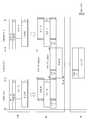
도 25는 기지국, 중계국 및 중계국 단말을 포함하는 무선통신 시스템에서 시간관계를 나타내는 또 다른 예이다. 도 25에서는 전달 지연 시간은 나타내지 않았다.25 is another example illustrating a time relationship in a wireless communication system including a base station, a relay station, and a relay station terminal. In Fig. 25, the propagation delay time is not shown.
도 25를 참조하면, 기지국의 매크로 서브프레임 즉, M-DL Tx 서브프레임과 M-UL Rx 서브프레임이 정렬되어 있지 않다(misalign). 중계국의 액세스 서브프레임 즉, A-DL Tx 서브프레임 및 A-UL Rx 서브프레임은 정렬되어 있다. 중계국의 액세서 서브프레임은 중계국의 백홀 서브프레임과 To 만큼의 오프셋 시간을 가진다. 즉, 중계국의 액세스 서브프레임이 백홀 서브프레임에 비해 To만큼 시간적으로 앞서 있다. 이러한 오프셋 시간으로 인해 중계국은 B-UL Tx 서브프레임의 13개의 심벌을 사용하여 백홀 상향링크 신호를 전송할 수 있다(노멀 CP의 경우). 또한, 중계국이 B-UL Tx 서브프레임에서 백홀 SRS(S’으로 표시)을 전송하는 경우 매크로 단말이 SRS를 전송하는 심벌과 심벌 단위의 동기화가 이루어지는 장점이 있다.Referring to FIG. 25, the macro subframe of the base station, that is, the M-DL Tx subframe and the M-UL Rx subframe are not aligned. The access subframes of the relay station, that is, the A-DL Tx subframe and the A-UL Rx subframe are aligned. The accessor subframe of the relay station has an offset time equal to To with the backhaul subframe of the relay station. That is, the access subframe of the relay station is temporally advanced by To compared to the backhaul subframe. This offset time allows the RS to transmit the backhaul uplink signal using 13 symbols of the B-UL Tx subframe (in the case of normal CP). In addition, when the RS transmits a backhaul SRS (indicated by S ′) in the B-UL Tx subframe, there is an advantage in that the symbol of the SRS and the symbol unit transmit the SRS.
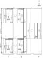
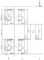
도 26 및 도 27은 기지국, 중계국 및 중계국 단말을 포함하는 무선통신 시스템에서 시간관계를 나타내는 또 다른 예이다. 도 26 및 도 27에서는 전달 지연 시간은 나타내지 않았다.26 and 27 are still another example illustrating time relationships in a wireless communication system including a base station, a relay station, and a relay station terminal. In FIG. 26 and FIG. 27, the propagation delay time is not shown.
도 26 및 도 27에 도시한 바와 같이 기지국은 M-UL Rx 서브프레임을 B-UL Rx 서브프레임과 심벌 단위의 동기화가 이루어지도록 앞으로 쉬프트 할 수 있다. 기지국의 B-DL Tx 서브프레임과 중계국의 B-DL Rx 서브프레임은 동기화되어 있다. 마찬가지로 기지국의 B-UL Rx 서브프레임과 중계국의 B-UL Tx 서브프레임은 동기화되어 있다. 중계국에서 액세스 서브프레임 즉, A-DL Tx 서브프레임 및 A-UL Rx 서브프레임은 동기화되어 있다.As shown in FIG. 26 and FIG. 27, the base station may shift the M-UL Rx subframe forward so that synchronization of the B-UL Rx subframe and symbol unit is performed. The B-DL Tx subframe of the base station and the B-DL Rx subframe of the relay station are synchronized. Similarly, the B-UL Rx subframe of the base station and the B-UL Tx subframe of the relay station are synchronized. At the relay station, the access subframe, i.e. the A-DL Tx subframe and the A-UL Rx subframe, are synchronized.
이러한 시간 관계에 의해 M-UL Rx 서브프레임과 B-UL Rx 서브프레임은 심벌 단위의 동기화가 이루어질 수 있다. 그러면 중계국은 백홀 SRS를 1 심벌 보다 작은 시간 영역에 배치하는 특수한 SRS를 전송하지 않아도 되는 장점이 있다. 심벌 단위의 동기화가 이루어지면 매크로 단말이 전송하는 SRS와 중계국이 전송하는 백홀 SRS 간의 간섭이 줄어들게 된다. 도 27은 도 26에 대하여 보호 구간을 다른 구간으로 표시한 해석의 차이이다.By such a time relationship, the M-UL Rx subframe and the B-UL Rx subframe may be synchronized in symbol units. The relay station then has the advantage of not having to transmit a special SRS that places the backhaul SRS in a time domain smaller than 1 symbol. When the symbol unit synchronization is performed, the interference between the SRS transmitted by the macro terminal and the backhaul SRS transmitted by the RS is reduced. FIG. 27 is a difference in interpretation in which the guard interval is displayed as another interval with respect to FIG. 26.
도 28은 기지국, 중계국 및 중계국 단말을 포함하는 무선통신 시스템에서 시간관계를 나타내는 또 다른 예이다. 도 28에서는 전달 지연 시간은 나타내지 않았다.28 is another example illustrating a time relationship in a wireless communication system including a base station, a relay station, and a relay station terminal. In Fig. 28, the propagation delay time is not shown.
도 28을 참조하면, 기지국의 매크로 서브프레임 및 백홀 서브프레임, 중계국의 백홀 서브프레임 및 액세스 서브프레임, 중계국 단말의 액세스 서브프레임들이 모두 정렬되어 있고, 동기화되어 있다.Referring to FIG. 28, the macro subframe and the backhaul subframe of the base station, the backhaul subframe and the access subframe of the relay station, and the access subframes of the relay station are all aligned and synchronized.
이러한 시간 관계에서 기지국은 B-DL Tx 서브프레임에서 보호 구간으로 인해 2개의 심벌이 낭비되며, 마찬가지로 중계국의 B-DL Rx 서브프레임에서도 보호 구간으로 인해 2개의 심벌이 낭비된다. 기지국의 B-UL Rx 서브프레임, 중계국의 B-UL Tx 서브프레임도 마찬가지이다. 보호 구간을 포함하는 심벌들에서 ‘U’로 표시된 부분이 낭비되는 영역이다. 이러한 심벌의 일부를 일부 심벌(partial symbol)이라 칭한다면, 일부 심벌의 낭비 문제는 앞서 언급한 바와 같이 새로운 심벌을 정의하여 사용함으로써 해결할 수 있다.In this time relationship, the base station wastes two symbols due to the guard period in the B-DL Tx subframe, and likewise wastes two symbols due to the guard period in the B-DL Rx subframe of the relay station. The same applies to the B-UL Rx subframe of the base station and the B-UL Tx subframe of the relay station. In the symbols including the guard interval, the portion marked with 'U' is wasted. If some of these symbols are called partial symbols, the waste of some symbols can be solved by defining and using new symbols as mentioned above.
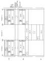
도 29는 기지국, 중계국 및 중계국 단말을 포함하는 무선통신 시스템에서 시간관계를 나타내는 또 다른 예이다. 도 29에서는 전달 지연 시간을 고려하여 표시한다.29 is another example illustrating a time relationship in a wireless communication system including a base station, a relay station, and a relay station terminal. In FIG. 29, the transmission delay time is considered and displayed.
이하에서 기지국과 중계국 간의 라운드 트립 지연(round trip delay) 시간을 RTDeNB-RN이라 표시하고, 중계국과 중계국 단말 간의 라운드 트립 지연 시간을 RTDRN-UE라고 표시한다. 전달 지연 시간은 기지국과 중계국 간에서 (RTDeNB-RN /2)일 수 있고, 중계국과 중계국 단말 간에서 (RTDRN-UE /2)일 수 있다.Hereinafter, the round trip delay time between the base station and the relay station is represented as RTDeNB-RN , and the round trip delay time between the relay station and the terminal is represented as RTDRN-UE . The propagation delay time may be (RTDeNB-RN / 2) between the base station and the relay station, and (RTDRN-UE / 2) between the relay station and the relay station.
도 29를 참조하면, 기지국에서 B-UL Rx 서브프레임은 M-UL Rx 서브프레임과 정렬되어 있다. 중계국은 전달 지연 시간을 고려하여, B-UL Tx 서브프레임이 기지국의 B-UL Rx 서브프레임보다 (RTDeNB-RN /2)만큼 앞서 위치할 수 있다. 또한, 중계국의 B-DL Rx 서브프레임은 기지국의 B-DL Tx 서브프레임보다 (RTDeNB-RN /2)만큼 후에 위치할 수 있다. 이러한 경우, 중계국의 B-UL Tx 서브프레임과 B-DL Rx 서브프레임은 RTDeNB-RN만큼 차이가 나게 위치할 수 있다. 즉, 중계국의 백홀 링크 서브프레임 즉, B-UL Tx 서브프레임 및 B-DL Rx 서브프레임은 정렬되어 있지 않다. 중계국에서 B-DL Rx 서브프레임과 A-DL Tx 서브프레임은 스위칭되어 사용되고, B-UL Tx 서브프레임과 A-UL Rx 서브프레임이 스위칭되어 사용된다. 이러한 관계를 고려하면 중계국의 A-DL Tx 서브프레임과 A-UL Rx 서브프레임도 RTDeNB-RN만큼 차이가 나게 위치하여야 한다.Referring to FIG. 29, the B-UL Rx subframe is aligned with the M-UL Rx subframe at the base station. In consideration of the propagation delay time, the RS may be positioned in advance of the B-UL Tx subframe by (RTDeNB-RN / 2) before the B-UL Rx subframe of the base station. In addition, the B-DL Rx subframe of the relay station may be located by (RTDeNB-RN / 2) after the B-DL Tx subframe of the base station. In this case, the B-UL Tx subframe and the B-DL Rx subframe of the RS may be located to be different from each other by the RTDeNB-RN . That is, the backhaul link subframes of the relay station, that is, the B-UL Tx subframe and the B-DL Rx subframe are not aligned. At the relay station, the B-DL Rx subframe and the A-DL Tx subframe are switched and used, and the B-UL Tx subframe and the A-UL Rx subframe are switched. Considering this relationship, the A-DL Tx subframe and the A-UL Rx subframe of the RS should also be located as different as RTDeNB-RN .
중계국과 중계국 단말 사이를 고려할 때 액세스 상향링크의 경우, 중계국 단말은 전달 지연 시간을 고려하여 (RTDRN-UE /2)만큼 앞서 액세스 상향링크 신호를 전송하면 된다. 즉, 중계국 단말의 A-UL Tx 서브프레임은 중계국의 A-UL Rx 서브프레임보다 (RTDRN-UE /2)만큼 앞서 위치하면 된다. 액세스 하향링크의 경우, 중계국의 A-DL Tx 서브프레임이 중계국 단말의 A-DL Rx 서브프레임보다 (RTDRN-UE /2)만큼 앞서 위치하면 된다. 그런데 이미 중계국의 A-DL Tx 서브프레임과 A-UL Rx 서브프레임 간에 RTDeNB-RN만큼 차이가 있기 때문에, 중계국 단말의 A-UL Tx 서브프레임과 A-DL Rx 서브프레임은 RTDRN-UE만큼 차이가 나는 것이 아니라, (RTDeNB-RN + RTDRN-UE)만큼 차이가 나게 위치하여야 한다.In consideration of the relay station and the relay station terminal, in case of access uplink, the relay station terminal may transmit the access uplink signal by (RTDRN-UE / 2) in advance in consideration of the propagation delay time. That is, the A-UL Tx subframe of the RS may be positioned ahead of the A-UL Rx subframe of the RS by (RTDRN-UE / 2). In the case of the access downlink, the A-DL Tx subframe of the RS may be positioned ahead of the A-DL Rx subframe of the RS by (RTDRN-UE / 2). However, since there is already a difference between the A-DL Tx subframe and the A-UL Rx subframe of the RS by RTDeNB-RN , the A-UL Tx subframe and the A-DL Rx subframe of the RS are as much as RTDRN-UE . It should not be different, but should be located as different as (RTDeNB-RN + RTDRN-UE ).
이러한 시간 관계에 의하면, 레거시 단말 예를 들어, 3GPP LTE release 8에 의해 동작하는 단말이 셀 내에 진입하는 등의 이유로 최초 접속(initial access)를 시도하는 경우, 레거시 단말은 목적국이 기지국인지 중계국인지 알 수 없으므로 종래 기지국과의 관계에서 사용하던 방법과 동일하게 PRACH 프리앰블을 전송한다. 중계국의 셀 크기가 작은 경우에도 큰 커버리지를 가지는 프리앰블을 전송해야 한다는 단점이 있을 수 있다. 그러나, 중계국에서 백홀 상향링크 신호 전송에 사용 가능한 무선자원을 최대화할 수 있는 장점이 있다.According to such a time relationship, when a legacy terminal, for example, a terminal operating by
도 30은 기지국, 중계국 및 중계국 단말을 포함하는 무선통신 시스템에서 시간관계를 나타내는 또 다른 예이다. 도 30에서는 전달 지연 시간을 고려하여 표시한다.30 is another example illustrating a time relationship in a wireless communication system including a base station, a relay station, and a relay station terminal. In FIG. 30, the transmission delay time is considered and displayed.
도 30을 참조하면, 중계국에서 하향링크 서브프레임 (즉, B-DL Tx 서브프레임과 A-DL Tx 서브프레임)과 상향링크 서브프레임(즉, B-UL Tx 서브프레임과 A-UL Rx 서브프레임)이 정렬되어 있다. 중계국의 B-UL Tx 서브프레임 및 B-DL Rx 서브프레임은 기지국의 B-UL Rx 서브프레임 및 B-DL Tx 서브프레임에 비해 (RTDeNB-RN /2)만큼 뒤에 위치할 수 있다.Referring to FIG. 30, a downlink subframe (that is, a B-DL Tx subframe and an A-DL Tx subframe) and an uplink subframe (that is, a B-UL Tx subframe and an A-UL Rx subframe at a relay station). ) Is aligned. The B-UL Tx subframe and the B-DL Rx subframe of the relay station may be located by (RTDeNB-RN / 2) behind the B-UL Rx subframe and the B-DL Tx subframe of the base station.
이러한 시간 관계는 레거시 단말 예컨대, 3GPP LTE release 8에 의해 동작하는 단말에 영향을 미치지 않는다. 다만, 중계국이 백홀 상향링크 전송에 사용할 수 있는 자원이 시간 영역에서 RTDeNB-RN만큼 줄어들게 되지만, 레거시 단말은 종래 A-DL Rx 서브프레임과 A-UL Tx 서브프레임 간의 시차를 동일하게 적용하여 동작할 수 있는 장점이 있다. 또한, 중계국은 만약 RTDeNB-RN이 보호 구간보다 큰 경우, 백홀 SRS를 매크로 단말이 전송하는 SRS와 다중화하여 전송할 수 있다.This time relationship does not affect legacy terminals, for example, terminals operated by
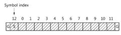
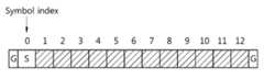
이하에서는 서브프레임의 심벌 단위로 기지국, 중계국 및 중계국 단말이 신호를 전송/수신하는 시간 관계를 설명한다. 이하의 도면에서 ‘G’가 표시된 부분은 보호 구간을 의미하고, ‘S’는 단말이 기지국으로 전송하는 SRS, ‘S’’는 중계국이 기지국으로 전송하는 백홀 SRS를 의미한다. 전달 지연 시간은 표시하지 않는다.Hereinafter, a time relationship for transmitting / receiving a signal by a base station, a relay station, and a relay terminal in units of symbols of a subframe will be described. In the following drawings, a portion marked with 'G' denotes a guard interval, and 'S' denotes an SRS transmitted by the terminal to the base station, and 'S' denotes a backhaul SRS transmitted by the relay station to the base station. The propagation delay time is not indicated.
도 31은 기지국, 중계국 및 중계국 단말간의 시간 관계(timing relationship)를 나타내는 일 예이다.31 shows an example of a timing relationship between a base station, a relay station, and a terminal of a relay station.
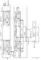
도 31을 참조하면, M-UL Rx 서브프레임, M-DL Tx 서브프레임, B-DL Rx 서브프레임, B-UL Tx 서브프레임, A-DL Rx 서브프레임, A-UL Tx 서브프레임들이 서브프레임 경계(subframe boundary)를 기준으로 정렬(align)되어 있다. B-DL Rx 서브프레임과 B-UL Tx 서브프레임은 서브프레임 경계는 정렬되어 있으나, 보호 구간이 포함되어 심벌 단위로는 정렬되어 있지 않다. B-DL Rx 서브프레임에 포함되는 보호 구간은 도 31과 다른 심벌에 포함될 수 있으며 B-UL Tx 서브프레임에 서 기지국으로부터 백홀 하향링크 신호를 수신하는 심벌의 시작점도 도 31과 다를 수 있다.Referring to FIG. 31, M-UL Rx subframes, M-DL Tx subframes, B-DL Rx subframes, B-UL Tx subframes, A-DL Rx subframes, and A-UL Tx subframes are subframes. It is aligned with respect to a subframe boundary. In the B-DL Rx subframe and the B-UL Tx subframe, the subframe boundary is aligned, but the guard interval is included and thus not aligned in symbol units. The guard period included in the B-DL Rx subframe may be included in a symbol different from FIG. 31, and the start point of the symbol for receiving the backhaul downlink signal from the base station in the B-UL Tx subframe may also be different from FIG.
도 32는 기지국, 중계국 및 중계국 단말 간의 시간 관계를 나타내는 다른 예이다.32 is another example illustrating a time relationship between a base station, a relay station, and a relay station terminal.
도 32를 참조하면, M-UL Rx 서브프레임 및 M-DL Tx 서브프레임에 대해 B-DL Rx 서브프레임, B-UL Tx 서브프레임, A-DL Rx 서브프레임, A-UL Tx 서브프레임들이 서브프레임 경계를 기준으로 다른 타이밍을 가진다. 즉, 중계국의 B-DL Rx 서브프레임 및 B-UL Tx 서브프레임, 중계국 단말의 A-DL Rx 서브프레임, A-UL Tx 서브프레임은 음(negative)의 오프셋 시간을 가진다. 기지국은 중계국 및 중계국 단말이 이러한 시간 관계를 가지도록 오프셋 시간에 대한 정보를 전송할 수 있다. B-UL Tx 서브프레임에서 백홀 SRS가 전송되는 심벌은 M-UL Rx 서브프레임에서 매크로 SRS를 수신하는 심벌과 심벌 단위로 정렬된다.Referring to FIG. 32, B-DL Rx subframes, B-UL Tx subframes, A-DL Rx subframes, and A-UL Tx subframes are subframes for M-UL Rx subframes and M-DL Tx subframes. It has different timing based on the frame boundary. That is, the B-DL Rx subframe and the B-UL Tx subframe of the relay station, the A-DL Rx subframe and the A-UL Tx subframe of the relay station have a negative offset time. The base station may transmit information on the offset time so that the relay station and the relay station terminal has such a time relationship. In the B-UL Tx subframe, a symbol on which a backhaul SRS is transmitted is aligned with a symbol receiving a macro SRS in an M-UL Rx subframe.
도 33은 기지국, 중계국 및 중계국 단말 간의 시간 관계를 나타내는 또 다른 예이다.33 is yet another example illustrating a time relationship between a base station, a relay station, and a relay station terminal.
도 33은 도 32와 달리 M-UL Rx 서브프레임 및 M-DL Tx 서브프레임에 대해 중계국의 B-DL Rx 서브프레임 및 B-UL Tx 서브프레임, 중계국 단말의 A-DL Rx 서브프레임 및 A-UL Tx 서브프레임이 양(positive)의 타이밍 오프셋을 가진다. B-UL Tx 서브프레임에서 전송되는 백홀 SRS는 매크로 단말이 전송하는 매크로 SRS(즉, M-UL Rx에서 수신하는 매크로 SRS)와 서로 다른 심벌(B-UL Tx 서브프레임의 13번째 심벌)에서 전송될 수 있다. 따라서, 매크로 SRS와 백홀 SRS가 서브프레임의 마지막 심벌(14번째 심벌)에서 다중화되어야 하는 것은 아니다.FIG. 33 illustrates a B-DL Rx subframe and a B-UL Tx subframe of a relay station, an A-DL Rx subframe and a A- of a relay station for an M-UL Rx subframe and an M-DL Tx subframe, unlike FIG. 32. The UL Tx subframe has a positive timing offset. The backhaul SRS transmitted in the B-UL Tx subframe is transmitted in a different symbol (the 13th symbol of the B-UL Tx subframe) from the macro SRS (that is, the macro SRS received in the M-UL Rx) transmitted by the macro terminal. Can be. Therefore, the macro SRS and the backhaul SRS do not have to be multiplexed in the last symbol (14th symbol) of the subframe.
도 34는 기지국, 중계국 및 중계국 단말 간의 시간 관계를 나타내는 또 다른 예이다.34 is another example illustrating a time relationship between a base station, a relay station, and a terminal of a relay station.
도 34를 참조하면, M-DL Tx 서브프레임, B-DL Rx 서브프레임, A-DL Rx 서브프레임은 서브프레임 경계를 기준으로 정렬되어 있다. 즉, 매크로 서브프레임과 백홀 서브프레임 및 액세스 서브프레임에서 하향링크 서브프레임들은 서브프레임 경계를 기준으로 정렬되어 있다. 반면, M-UL Rx 서브프레임에 대해 B-UL Tx 서브프레임 및 A-UL Tx 서브프레임은 서브프레임 경계를 기준으로 정렬되어 있지 않다. 기지국은 추가적인 시간 보정 명령(additional timing adjustment command, TA’으로 표시)을 중계국이나 단말에게 전송함으로써 이러한 시간 관계를 적용할 수 있다. 여기서, 추가적인 시간 보정 명령은 전달 지연 시간 또는 라운드 트립 시간을 보상하기 위해 기존의 시간 보정 명령에 추가적으로 전송되는 신호일 수 있다.Referring to FIG. 34, M-DL Tx subframes, B-DL Rx subframes, and A-DL Rx subframes are aligned based on subframe boundaries. That is, downlink subframes in the macro subframe, the backhaul subframe, and the access subframe are aligned based on the subframe boundary. On the other hand, for the M-UL Rx subframe, the B-UL Tx subframe and the A-UL Tx subframe are not aligned based on the subframe boundary. The base station may apply this time relationship by transmitting an additional timing adjustment command (denoted as TA ′) to the relay station or the terminal. Here, the additional time correction command may be a signal additionally transmitted to the existing time correction command to compensate for the propagation delay time or the round trip time.
기존의 레거시 단말은 추가적 시간 보정 명령을 이해할 수 없어 이러한 시간 관계를 적용하기 어려우나, 추가적인 시간 보정 명령(TA’)을 이해할 수 있는 단말에게는 적용할 수 있다. 도 34에서는 음의 값을 가지는 TA’을 수행하는 것을 예시하고 있다. 즉, B-UL Tx 서브프레임 및 A-UL Tx 서브프레임이 시간적으로 뒤로 쉬프트 되는 것을 예시하고 있다. 이러한 시간 관계에서 B-UL Tx 서브프레임에서 전송되는 백홀 SRS와 매크로 SRS는 심벌 단위로 정렬될 수 있다.Existing legacy terminal is difficult to apply this time relationship because it can not understand the additional time correction command, it can be applied to a terminal that can understand the additional time correction command (TA '). 34 exemplarily performs TA ′ having a negative value. That is, the B-UL Tx subframe and the A-UL Tx subframe are shifted backward in time. In this time relationship, the backhaul SRS and the macro SRS transmitted in the B-UL Tx subframe may be aligned in symbol units.
도 35는 기지국, 중계국 및 중계국 단말 간의 시간 관계를 나타내는 또 다른 예이다.35 is yet another example illustrating a time relationship between a base station, a relay station, and a relay station terminal.
도 35는 도 34와 마찬가지로 M-DL Tx 서브프레임, B-DL Rx 서브프레임, A-DL Rx 서브프레임은 서브프레임 경계를 기준으로 정렬되어 있다. 반면, M-UL Rx 서브프레임, B-UL Tx 서브프레임, A-UL Tx 서브프레임은 서브프레임 경계를 기준으로 정렬되어 있지 않다. 도 35에서 도 34와의 차이는 추가적인 시간 보정 명령이 양의 값으로 설정되는 차이가 있다. 즉, B-UL Tx 서브프레임 및 A-UL Tx 서브프레임이 시간적으로 앞으로 쉬프트 되는 것을 예시하고 있다.FIG. 35 illustrates that the M-DL Tx subframe, the B-DL Rx subframe, and the A-DL Rx subframe are aligned based on the subframe boundary like FIG. 34. On the other hand, the M-UL Rx subframe, the B-UL Tx subframe, and the A-UL Tx subframe are not aligned based on the subframe boundary. 35 differs from FIG. 34 in that an additional time correction command is set to a positive value. That is, the B-UL Tx subframe and the A-UL Tx subframe are shifted forward in time.
도 36은 기지국, 중계국 간의 타이밍 관계를 나타내는 또 다른 예이다.36 is another example showing the timing relationship between the base station and the relay station.
M-DL Tx 서브프레임, B-DL Rx 서브프레임, A-DL Rx 서브프레임은 서브프레임 경계를 기준으로 정렬되어 있다. M-UL Rx 서브프레임, B-UL Tx 서브프레임, A-UL Tx 서브프레임에 대해 양의 값을 가지는 시간 보정 명령이 적용된다. 도 35와 비교하여 B-UL Tx 서브프레임 및 A-UL Tx 서브프레임이 쉬프트 되는 정도가 1 심벌 이상이라는 차이가 있다. 예를 들어, (1 심벌 + 보호 구간)만큼 B-UL Tx 서브프레임 및 A-UL Tx 서브프레임이 앞으로 쉬프트 될 수 있다. B-UL Tx 서브프레임과 A-UL Tx 서브프레임이 모두 앞으로 쉬프트 되기 때문에 시간적으로 서로 겹치지 않는다.The M-DL Tx subframe, the B-DL Rx subframe, and the A-DL Rx subframe are aligned based on the subframe boundary. A positive time correction command is applied to the M-UL Rx subframe, the B-UL Tx subframe, and the A-UL Tx subframe. Compared to FIG. 35, there is a difference that the degree of shifting the B-UL Tx subframe and the A-UL Tx subframe is one symbol or more. For example, the B-UL Tx subframe and the A-UL Tx subframe may be shifted forward by (1 symbol + guard interval). Since the B-UL Tx subframe and the A-UL Tx subframe are both shifted forward, they do not overlap each other in time.
B-UL Tx 서브프레임이 1 심벌 이상 앞으로 쉬프트되는 경우, 보호 구간을 제외한 첫번째 심벌에서 백홀 SRS를 전송할 수 있다. 그러면, 도 36에 도시된 바와 같이 M-UL Rx의 매크로 SRS와 비교하여 심벌 단위로 정렬될 수 있다. 매크로 SRS와 백홀 SRS가 다중화되어 전송될 수 있으므로 M-UL Rx에서 수신되는 PUSCH, PUCCH와 충돌을 피할 수 있다.When the B-UL Tx subframe is shifted forward by 1 symbol or more, the backhaul SRS may be transmitted in the first symbol except the guard period. Then, as shown in FIG. 36, the data may be aligned in symbol units as compared with the macro SRS of the M-UL Rx. Since the macro SRS and the backhaul SRS may be multiplexed and transmitted, collision with the PUSCH and the PUCCH received in the M-UL Rx may be avoided.
백홀 SRS를 전송하는 B-UL Tx 서브프레임에서 백홀 상향링크 데이터를 전송할 수 있는 심벌의 수를 증가시키기 위해 기지국은 매크로 단말에게 항상 축소 포맷(shortened format)으로 데이터를 전송하도록 할 수 있다. 예를 들어, 매크로 SRS의 전송 여부와 관계없이 항상 매크로 단말이 축소 포맷으로 데이터를 전송하게 하는 것이다. 또는 매크로 단말이 매크로 SRS를 전송하지 않는 서브프레임을 중계국에게 알려주고 기지국은 그러한 서브프레임을 축소 포맷을 사용하는 서브프레임으로 설정할 수 있다. 그러면 중계국은 백홀 SRS의 전송 여부, R-PUSCH 의 포맷 등을 결정할 때 사용 가능한 백홀 자원의 양을 고려할 수 있다. 매크로 SRS 전송 타이밍 및 백홀 SRS 전송 타이밍 정보를 기지국과 중계국 간에 공유함으로써 자원활용을 높일 수 있다.In order to increase the number of symbols capable of transmitting backhaul uplink data in the B-UL Tx subframe transmitting the backhaul SRS, the base station may always transmit data to the macro terminal in a shortened format. For example, the macro terminal always transmits data in a reduced format regardless of whether or not the macro SRS is transmitted. Alternatively, the macro terminal informs the relay station of a subframe not transmitting the macro SRS, and the base station may set the subframe as a subframe using a reduced format. Then, the RS may consider the amount of available backhaul resources when determining whether to transmit the backhaul SRS, the format of the R-PUSCH, and the like. Resource utilization can be enhanced by sharing macro SRS transmission timing and backhaul SRS transmission timing information between the base station and the relay station.
도 37 및 도 38은 백홀 SRS를 전송하는 B-UL Tx 서브프레임의 심벌 인덱스를 예시한다.37 and 38 illustrate a symbol index of a B-UL Tx subframe that transmits a backhaul SRS.
도 37 및 도 38에서 도시한 바와 같이 B-UL Tx 서브프레임의 보호 구간을 제외한 첫번째 심벌에서 백홀 SRS를 전송할 수 있다. 이러한 경우, B-UL Tx 서브프레임의 심벌 인덱스는 보호 구간을 제외한 시간 구간에서 심벌 단위(예를 들면 OFDM 심벌 또는 SC-FDMA 심벌 단위)로 인덱스를 부여할 수 있다. 도 37에서는 백홀 SRS가 전송되는 첫번째 심벌의 인덱스를 12로 하고, 이후의 심벌에 대해 차례로 0부터 11까지 인덱스를 부여하고 있다. 이러한 심벌 인덱스 부여 방법에 의해 물리적 자원 위치에도 불구하고 백홀 SRS는 항상 심벌 12에서 전송된다고 표현할 수 있다. 도 38에서는 백홀 SRS가 전송되는 첫번째 심벌의 인덱스를 0으로 하고 이후의 심벌에 대해 차례로 1부터 12까지 인덱스를 부여하고 있다. 백홀 SRS가 전송되는 경우, B-UL Tx 서브프레임에서 13개의 심벌이 사용되고, 백홀 SRS가 전송되지 않는 경우, B-UL Tx 서브프레임에서 12개의 심벌이 사용될 수 있다.As illustrated in FIGS. 37 and 38, the backhaul SRS may be transmitted in the first symbol except for the guard period of the B-UL Tx subframe. In this case, the symbol index of the B-UL Tx subframe may be indexed in symbol units (for example, OFDM symbols or SC-FDMA symbol units) in the time interval except the guard period. In FIG. 37, the index of the first symbol on which the backhaul SRS is transmitted is set to 12, and indexes from 0 to 11 are sequentially assigned to subsequent symbols. By the symbol index granting method, the backhaul SRS may always be expressed in
도 39는 소스국 및 목적국을 나타내는 블록도이다.39 is a block diagram showing a source station and a destination station.
소스국(10)은 기지국일 수 있으며, 소스국(10)은 프로세서(processor, 11), 메모리(memory, 12) 및 RF부(RF(radio frequency) unit, 13)를 포함한다. 프로세서(11)는 제안된 기능, 과정 및/또는 방법을 구현한다. 즉, 목적국으로 동기 신호를 전송하고, 오프셋 시간, 추가적인 시간 보정 명령(TA’)를 전송할 수 있다. 무선 인터페이스 프로토콜의 계층들은 프로세서(11)에 의해 구현될 수 있다. 메모리(12)는 프로세서(11)와 연결되어, 프로세서(11)를 구동하기 위한 다양한 정보를 저장한다. RF부(13)는 프로세서(11)와 연결되어, 무선 신호를 전송 및/또는 수신한다.The
목적국(20)은 단말 즉, 중계국, 매크로 단말 또는 중계국 단말일 수 있다. 목적국(20)은 프로세서(21), 메모리(22) 및 RF부(23)를 포함한다. 프로세서(21)는 동기 신호, 오프셋 시간, 추가적인 시간 보정 명령을 수신하여 신호를 전송 또는 수신하는 서브프레임의 시간을 결정한다. 무선 인터페이스 프로토콜의 계층들은 프로세서(21)에 의해 구현될 수 있다. 메모리(22)는 프로세서(21)와 연결되어, 프로세서(21)를 구동하기 위한 다양한 정보를 저장한다. RF부(23)는 프로세서(21)와 연결되어, 무선 신호를 전송 및/또는 수신한다.The target station 20 may be a terminal, that is, a relay station, a macro terminal, or a relay station terminal. The target station 20 includes a
프로세서(11,21)는 ASIC(application-specific integrated circuit), 다른 칩셋, 논리 회로, 데이터 처리 장치 및/또는 베이스밴드 신호 및 무선 신호를 상호 변환하는 변환기를 포함할 수 있다. 도 6의 전송기는 프로세서(51,61) 내에 구현될 수 있다. 메모리(12,22)는 ROM(read-only memory), RAM(random access memory), 플래쉬 메모리, 메모리 카드, 저장 매체 및/또는 다른 저장 장치를 포함할 수 있다. RF부(13,23)는 무선 신호를 전송 및/또는 수신하는 하나 이상의 안테나를 포함한다. 실시예가 소프트웨어로 구현될 때, 상술한 기법은 상술한 기능을 수행하는 모듈(과정, 기능 등)로 구현될 수 있다. 모듈은 메모리(12,22)에 저장되고, 프로세서(11,21)에 의해 실행될 수 있다. 메모리(12,22)는 프로세서(11,21) 내부 또는 외부에 있을 수 있고, 잘 알려진 다양한 수단으로 프로세서(11,21)와 연결될 수 있다.The
이상 본 발명에 대하여 실시예를 참조하여 설명하였지만, 해당 기술 분야의 통상의 지식을 가진 자는 본 발명의 기술적 사상 및 영역으로부터 벗어나지 않는 범위 내에서 본 발명을 다양하게 수정 및 변경시켜 실시할 수 있음을 이해할 수 있을 것이다. 따라서 상술한 실시예에 한정되지 않고, 본 발명은 이하의 특허청구범위의 범위 내의 모든 실시예들을 포함한다고 할 것이다.While the present invention has been particularly shown and described with reference to exemplary embodiments thereof, it will be understood by those skilled in the art that various changes and modifications may be made therein without departing from the spirit and scope of the invention. You will understand. Therefore, the present invention is not limited to the above-described embodiment, and the present invention will include all embodiments within the scope of the following claims.
Claims (14)
Translated fromKorean기지국으로부터 오프셋 시간 정보를 수신하는 단계;
상기 오프셋 시간 정보에 따라 중계국 단말에게 액세스 하향링크 신호를 전송하는 액세스 하향링크 전송 서브프레임 및 상기 기지국으로부터 백홀 하향링크 신호를 수신하는 백홀 하향링크 수신 서브프레임 간의 시간 차이를 설정하는 단계;
상기 백홀 하향링크 전송 서브프레임에서 중계국 단말에게 제어 신호를 전송하는 단계; 및
상기 백홀 하향링크 수신 서브프레임에서 상기 기지국으로부터 백홀 하향링크 신호를 수신하는 단계를 포함하는 것을 특징으로 하는 방법.In a method of transmitting and receiving a signal of a relay station in a wireless communication system,
Receiving offset time information from a base station;
Setting a time difference between an access downlink transmission subframe that transmits an access downlink signal to a relay station terminal and a backhaul downlink reception subframe that receives a backhaul downlink signal from the base station according to the offset time information;
Transmitting a control signal to a relay station terminal in the backhaul downlink transmission subframe; And
Receiving a backhaul downlink signal from the base station in the backhaul downlink receiving subframe.
기지국으로부터 오프셋 시간 정보를 수신하는 단계;
상기 오프셋 시간 정보에 따라 중계국 단말로부터 액세스 상향링크 신호를 수신하는 액세스 상향링크 수신 서브프레임 및 상기 기지국에게 백홀 상향링크 신호를 전송하는 백홀 상향링크 전송 서브프레임 간의 시간 차이를 설정하는 단계;
상기 백홀 상향링크 전송 서브프레임에서 상기 기지국에게 백홀 상향링크 신호를 전송하는 단계를 포함하는 것을 특징으로 하는 방법.In a method of transmitting and receiving a signal of a relay station in a wireless communication system,
Receiving offset time information from a base station;
Setting a time difference between an access uplink reception subframe for receiving an access uplink signal from a relay station terminal and a backhaul uplink transmission subframe for transmitting a backhaul uplink signal to the base station according to the offset time information;
And transmitting a backhaul uplink signal to the base station in the backhaul uplink transmission subframe.
상기 RF부에 연결되는 프로세서를 포함하되, 상기 프로세서는
기지국으로부터 오프셋 시간 정보를 수신하고, 상기 오프셋 시간 정보에 따라 중계국 단말에게 액세스 하향링크 신호를 전송하는 액세스 하향링크 전송 서브프레임 및 상기 기지국으로부터 백홀 하향링크 신호를 수신하는 백홀 하향링크 수신 서브프레임 간의 시간 차이를 설정하고, 상기 백홀 하향링크 전송 서브프레임에서 중계국 단말에게 제어 신호를 전송하며, 상기 백홀 하향링크 수신 서브프레임에서 상기 기지국으로부터 백홀 하향링크 신호를 수신하는 것을 특징으로 하는 무선통신 시스템에서 신호의 송수신 장치.RF unit for transmitting and receiving a radio signal; And
A processor connected to the RF unit, wherein the processor
Time between an access downlink transmission subframe that receives offset time information from a base station and transmits an access downlink signal to a relay station terminal according to the offset time information and a backhaul downlink reception subframe that receives a backhaul downlink signal from the base station. Setting a difference, transmitting a control signal to a relay station in the backhaul downlink transmission subframe, and receiving a backhaul downlink signal from the base station in the backhaul downlink receiving subframe. Transceiver.
상기 RF부에 연결되는 프로세서를 포함하되, 상기 프로세서는 기지국으로부터 오프셋 시간 정보를 수신하고, 상기 오프셋 시간 정보에 따라 중계국 단말로부터 액세스 상향링크 신호를 수신하는 액세스 상향링크 수신 서브프레임 및 상기 기지국에게 백홀 상향링크 신호를 전송하는 백홀 상향링크 전송 서브프레임 간의 시간 차이를 설정하고, 상기 백홀 상향링크 전송 서브프레임에서 상기 기지국에게 백홀 상향링크 신호를 전송하는 것을 특징으로 하는 무선통신 시스템에서 신호의 송수신 장치.RF unit for transmitting and receiving a radio signal; And
And a processor coupled to the RF unit, wherein the processor receives offset time information from a base station and receives an access uplink receiving subframe from the relay station terminal according to the offset time information and a backhaul to the base station. And a time difference between a backhaul uplink transmission subframe for transmitting an uplink signal, and transmitting a backhaul uplink signal to the base station in the backhaul uplink transmission subframe.
Priority Applications (7)
| Application Number | Priority Date | Filing Date | Title |
|---|---|---|---|
| JP2011550063AJP5373924B2 (en) | 2009-02-16 | 2010-02-16 | Method and apparatus for signal transmission / reception of relay station in wireless communication system |
| EP10741438.5AEP2398161A4 (en) | 2009-02-16 | 2010-02-16 | Method and apparatus for transmitting and receiving signal from relay station in radio communication system |
| US13/201,805US8576900B2 (en) | 2008-06-15 | 2010-02-16 | Method and apparatus for transmitting and receiving signal from relay station in radio communication system |
| PCT/KR2010/000950WO2010093221A2 (en) | 2009-02-16 | 2010-02-16 | Method and apparatus for transmitting and receiving signal from relay station in radio communication system |
| CN201080008035.XACN102318229B (en) | 2009-02-16 | 2010-02-16 | Method and apparatus for transmitting and receiving signals from a relay station in a wireless communication system |
| US14/044,577US9001876B2 (en) | 2009-02-16 | 2013-10-02 | Method and apparatus for transmitting and receiving signal from relay station in radio communication system |
| US14/657,976US9698946B2 (en) | 2009-02-16 | 2015-03-13 | Method and apparatus for transmitting and receiving signal from relay station in radio communication system |
Applications Claiming Priority (10)
| Application Number | Priority Date | Filing Date | Title |
|---|---|---|---|
| US15295109P | 2009-02-16 | 2009-02-16 | |
| US61/152,951 | 2009-02-16 | ||
| US18726609P | 2009-06-15 | 2009-06-15 | |
| US61/187,266 | 2009-06-15 | ||
| US21972709P | 2009-06-23 | 2009-06-23 | |
| US61/219,727 | 2009-06-23 | ||
| US23616209P | 2009-08-24 | 2009-08-24 | |
| US61/236,162 | 2009-08-24 | ||
| US29886210P | 2010-01-27 | 2010-01-27 | |
| US61/298,862 | 2010-01-27 |
Publications (2)
| Publication Number | Publication Date |
|---|---|
| KR20100093503Atrue KR20100093503A (en) | 2010-08-25 |
| KR101595131B1 KR101595131B1 (en) | 2016-02-18 |
Family
ID=56291154
Family Applications (1)
| Application Number | Title | Priority Date | Filing Date |
|---|---|---|---|
| KR1020100013907AActiveKR101595131B1 (en) | 2008-06-15 | 2010-02-16 | Method and apparatus of transmitting or receiving signal for relay station in wireless communication system |
Country Status (2)
| Country | Link |
|---|---|
| US (2) | US9001876B2 (en) |
| KR (1) | KR101595131B1 (en) |
Cited By (1)
| Publication number | Priority date | Publication date | Assignee | Title |
|---|---|---|---|---|
| KR20140024341A (en)* | 2011-03-25 | 2014-02-28 | 엘지전자 주식회사 | Backhaul link subframe structure in mobile communication system and method for transmitting information thereof |
Families Citing this family (13)
| Publication number | Priority date | Publication date | Assignee | Title |
|---|---|---|---|---|
| KR101595131B1 (en)* | 2009-02-16 | 2016-02-18 | 엘지전자 주식회사 | Method and apparatus of transmitting or receiving signal for relay station in wireless communication system |
| JP6207397B2 (en) | 2011-11-04 | 2017-10-04 | 三菱電機株式会社 | Mobile communication system |
| US10344597B2 (en)* | 2015-08-17 | 2019-07-09 | United Technologies Corporation | Cupped contour for gas turbine engine blade assembly |
| US11283536B2 (en) | 2015-09-25 | 2022-03-22 | Telefonaktiebolaget Lm Ericsson (Publ) | Method and network node for reducing interference in a wireless network |
| CN109076565B (en)* | 2016-05-10 | 2023-10-03 | 株式会社Ntt都科摩 | Wireless communication device and wireless communication method |
| US10375707B2 (en)* | 2016-08-04 | 2019-08-06 | Qualcomm Incorporated | Dynamic resource allocation in wireless network |
| CN108282303B (en)* | 2017-01-06 | 2023-03-10 | 北京三星通信技术研究有限公司 | Signal transmission method and device |
| EP3503637A3 (en)* | 2017-12-21 | 2019-09-04 | ASUSTek Computer Inc. | Method and apparatus for transmission and reception in backhaul link in a wireless communication system |
| US10652059B2 (en)* | 2018-06-19 | 2020-05-12 | CoreTigo, Ltd. | Mission critical wireless communication link master gateway |
| US11503555B2 (en)* | 2018-08-17 | 2022-11-15 | Qualcomm Incorporated | Dynamic timing adjustment for new radio integrated access and backhaul node |
| US11234277B2 (en)* | 2018-09-27 | 2022-01-25 | Samsung Electronics Co., Ltd. | Power control in integrated access and backhaul |
| CN114041313B (en)* | 2019-05-28 | 2025-03-11 | 苹果公司 | Method in integrated access and backhaul system |
| WO2020243339A1 (en) | 2019-05-31 | 2020-12-03 | Apple Inc. | Dynamic soft resource signaling in relay networks |
Citations (2)
| Publication number | Priority date | Publication date | Assignee | Title |
|---|---|---|---|---|
| US6108364A (en)* | 1995-08-31 | 2000-08-22 | Qualcomm Incorporated | Time division duplex repeater for use in a CDMA system |
| JP2007166620A (en)* | 2005-12-10 | 2007-06-28 | Samsung Electronics Co Ltd | Apparatus and method for adjusting operation conversion gap in multihop relay cellular network |
Family Cites Families (12)
| Publication number | Priority date | Publication date | Assignee | Title |
|---|---|---|---|---|
| US8040826B2 (en) | 2006-03-03 | 2011-10-18 | Samsung Electronics Co., Ltd | Apparatus and method for supporting relay service in a multi-hop relay broadband wireless access communication system |
| JP5125027B2 (en) | 2006-08-17 | 2013-01-23 | 富士通株式会社 | Radio relay communication method, radio base station and radio relay station in radio communication system |
| JP4907260B2 (en) | 2006-08-18 | 2012-03-28 | 富士通株式会社 | Radio relay system, radio relay station apparatus, and radio communication method |
| US8462676B2 (en)* | 2006-10-17 | 2013-06-11 | Intel Corporation | Frame structure for support of large delay spread deployment scenarios |
| KR100953590B1 (en) | 2007-03-02 | 2010-04-21 | 삼성전자주식회사 | Frame offset negotiation apparatus and method between base station and relay station in broadband wireless communication system using multi-hop relay method |
| KR100895177B1 (en) | 2007-04-16 | 2009-05-04 | 삼성전자주식회사 | Switch control method and apparatus for separating transmission signal from repeater using TD system |
| US8032183B2 (en) | 2007-07-16 | 2011-10-04 | Alcatel Lucent | Architecture to support network-wide multiple-in-multiple-out wireless communication |
| US8681666B2 (en)* | 2007-10-01 | 2014-03-25 | Qualcomm Incorporated | Partial discarding of cyclic prefix for efficient TDD or half-duplex FDD operation |
| US20090279458A1 (en)* | 2008-03-24 | 2009-11-12 | Texas Instruments Incorporated | Uplink and Downlink Hybrid Automatic Repeat Request In Time Division Multiplex Communications |
| WO2010093221A2 (en) | 2009-02-16 | 2010-08-19 | 엘지전자주식회사 | Method and apparatus for transmitting and receiving signal from relay station in radio communication system |
| KR101595131B1 (en)* | 2009-02-16 | 2016-02-18 | 엘지전자 주식회사 | Method and apparatus of transmitting or receiving signal for relay station in wireless communication system |
| EP2398161A4 (en)* | 2009-02-16 | 2017-05-10 | LG Electronics Inc. | Method and apparatus for transmitting and receiving signal from relay station in radio communication system |
- 2010
- 2010-02-16KRKR1020100013907Apatent/KR101595131B1/enactiveActive
- 2013
- 2013-10-02USUS14/044,577patent/US9001876B2/enactiveActive
- 2015
- 2015-03-13USUS14/657,976patent/US9698946B2/enactiveActive
Patent Citations (3)
| Publication number | Priority date | Publication date | Assignee | Title |
|---|---|---|---|---|
| US6108364A (en)* | 1995-08-31 | 2000-08-22 | Qualcomm Incorporated | Time division duplex repeater for use in a CDMA system |
| JP2007110754A (en)* | 1995-08-31 | 2007-04-26 | Qualcomm Inc | Time division duplex repeater for use in a CDMA system |
| JP2007166620A (en)* | 2005-12-10 | 2007-06-28 | Samsung Electronics Co Ltd | Apparatus and method for adjusting operation conversion gap in multihop relay cellular network |
Cited By (3)
| Publication number | Priority date | Publication date | Assignee | Title |
|---|---|---|---|---|
| KR20140024341A (en)* | 2011-03-25 | 2014-02-28 | 엘지전자 주식회사 | Backhaul link subframe structure in mobile communication system and method for transmitting information thereof |
| EP2690799A4 (en)* | 2011-03-25 | 2014-10-08 | Lg Electronics Inc | Backhaul link subframe structure in mobile communication system and method for transmitting information thereof |
| US9184893B2 (en) | 2011-03-25 | 2015-11-10 | Lg Electronics Inc. | Backhaul link subframe structure in mobile communication system and method for transmitting information thereof |
Also Published As
| Publication number | Publication date |
|---|---|
| US9001876B2 (en) | 2015-04-07 |
| US20140029508A1 (en) | 2014-01-30 |
| KR101595131B1 (en) | 2016-02-18 |
| US20150188676A1 (en) | 2015-07-02 |
| US9698946B2 (en) | 2017-07-04 |
Similar Documents
| Publication | Publication Date | Title |
|---|---|---|
| KR101595131B1 (en) | Method and apparatus of transmitting or receiving signal for relay station in wireless communication system | |
| JP5373924B2 (en) | Method and apparatus for signal transmission / reception of relay station in wireless communication system | |
| US8576900B2 (en) | Method and apparatus for transmitting and receiving signal from relay station in radio communication system | |
| US8773971B2 (en) | Method and apparatus for transmitting/receiving a signal in a wireless communication system | |
| US9553655B2 (en) | Data-receiving method and apparatus for relay station in wireless communication system | |
| US8982766B2 (en) | Signal transmission method performed by relay station in wireless communication system and apparatus thereof | |
| US9014082B2 (en) | Method and device for signal transmission on a wireless communications system | |
| KR101339477B1 (en) | Method of using component carrier for relay station in multi-carrier system and relay station | |
| US8665775B2 (en) | Method and apparatus in which a relay station makes a hybrid automatic repeat request in a multi-carrier system | |
| US8503348B2 (en) | Method and apparatus in which a relay station transmits a sounding reference signal | |
| WO2011034350A2 (en) | Method and apparatus for transmitting and receiving signal in relay station | |
| EP2448146B1 (en) | Method and device for signal transmission on a wireless communications system | |
| KR20120052971A (en) | Relay station and method of relay station transmitting backhaul uplink signal | |
| US8804602B2 (en) | Method and apparatus for transmitting frame in wireless communication system including relay station | |
| KR101639081B1 (en) | Method and apparatus for transmitting signal in wireless communication system | |
| EP2613457B1 (en) | Method for transmitting signals in a communication system including a relay station | |
| WO2011002263A2 (en) | Method and apparatus for receiving control information of relay station in wireless communication system including relay station | |
| US8867499B2 (en) | Method and apparatus for transmitting a signal in a wireless communication system | |
| WO2010137839A2 (en) | Method and apparatus in which a relay station makes a hybrid automatic repeat request in a multi-carrier system | |
| KR101637588B1 (en) | Method and apparatus for transmitting or receiving signal in wireless communication system | |
| CN102498678A (en) | Method and device for transmitting and receiving signals in a relay station |
Legal Events
| Date | Code | Title | Description |
|---|---|---|---|
| PA0109 | Patent application | Patent event code:PA01091R01D Comment text:Patent Application Patent event date:20100216 | |
| PG1501 | Laying open of application | ||
| A201 | Request for examination | ||
| PA0201 | Request for examination | Patent event code:PA02012R01D Patent event date:20150216 Comment text:Request for Examination of Application Patent event code:PA02011R01I Patent event date:20100216 Comment text:Patent Application | |
| E902 | Notification of reason for refusal | ||
| PE0902 | Notice of grounds for rejection | Comment text:Notification of reason for refusal Patent event date:20150828 Patent event code:PE09021S01D | |
| E701 | Decision to grant or registration of patent right | ||
| PE0701 | Decision of registration | Patent event code:PE07011S01D Comment text:Decision to Grant Registration Patent event date:20151118 | |
| GRNT | Written decision to grant | ||
| PR0701 | Registration of establishment | Comment text:Registration of Establishment Patent event date:20160211 Patent event code:PR07011E01D | |
| PR1002 | Payment of registration fee | Payment date:20160211 End annual number:3 Start annual number:1 | |
| PG1601 | Publication of registration | ||
| FPAY | Annual fee payment | Payment date:20190114 Year of fee payment:4 | |
| PR1001 | Payment of annual fee | Payment date:20190114 Start annual number:4 End annual number:4 | |
| FPAY | Annual fee payment | Payment date:20200114 Year of fee payment:5 | |
| PR1001 | Payment of annual fee | Payment date:20200114 Start annual number:5 End annual number:5 | |
| PR1001 | Payment of annual fee | Payment date:20210114 Start annual number:6 End annual number:6 | |
| PR1001 | Payment of annual fee | Payment date:20230109 Start annual number:8 End annual number:8 | |
| PR1001 | Payment of annual fee | Payment date:20240109 Start annual number:9 End annual number:9 |