KR20100092082A - Apparatus for controlling power and method using the apparatus - Google Patents
Apparatus for controlling power and method using the apparatusDownload PDFInfo
- Publication number
- KR20100092082A KR20100092082AKR1020090011267AKR20090011267AKR20100092082AKR 20100092082 AKR20100092082 AKR 20100092082AKR 1020090011267 AKR1020090011267 AKR 1020090011267AKR 20090011267 AKR20090011267 AKR 20090011267AKR 20100092082 AKR20100092082 AKR 20100092082A
- Authority
- KR
- South Korea
- Prior art keywords
- power
- microcomputer
- state information
- driving program
- boot
- Prior art date
- Legal status (The legal status is an assumption and is not a legal conclusion. Google has not performed a legal analysis and makes no representation as to the accuracy of the status listed.)
- Ceased
Links
Images


Classifications
- G—PHYSICS
- G06—COMPUTING OR CALCULATING; COUNTING
- G06F—ELECTRIC DIGITAL DATA PROCESSING
- G06F12/00—Accessing, addressing or allocating within memory systems or architectures
- G—PHYSICS
- G06—COMPUTING OR CALCULATING; COUNTING
- G06F—ELECTRIC DIGITAL DATA PROCESSING
- G06F9/00—Arrangements for program control, e.g. control units
- G06F9/06—Arrangements for program control, e.g. control units using stored programs, i.e. using an internal store of processing equipment to receive or retain programs
- G06F9/22—Microcontrol or microprogram arrangements
- G06F9/24—Loading of the microprogram
Landscapes
- Engineering & Computer Science (AREA)
- Theoretical Computer Science (AREA)
- Software Systems (AREA)
- Physics & Mathematics (AREA)
- General Engineering & Computer Science (AREA)
- General Physics & Mathematics (AREA)
- Power Sources (AREA)
Abstract
Description
Translated fromKorean본 발명은 전원을 효율적으로 관리할 수 있는 전원제어 장치 및 이를 이용한 방법에 관한 것이다.The present invention relates to a power supply control apparatus capable of efficiently managing a power source and a method using the same.
현재 디지털 텔레비전 수신기는 음성과 영상뿐만 아니라, 부가정보를 제공할 수 있는 데이터 방송이 가능하다. 데이터방송은 텔레비전 영상신호에 정보를 다중화해 전송하거나 별도의 채널을 통해 디지털 텔레비전 수신기나 컴퓨터를 보유한 사용자에게 문자정보, 정지영상, 상품정보, 전자 프로그램 안내정보(Electronic Program Guide; EPG)를 포함한 멀티미디어 정보를 제공할 수 있다.Currently, digital television receivers are capable of broadcasting data that can provide additional information as well as audio and video. Data broadcasting includes multiplexing and transmitting information on television video signals or multimedia information including text information, still images, product information, and electronic program guides (EPGs) to users with digital television receivers or computers through separate channels. Information can be provided.
최근 디지털 텔레비전 수신기의 응용 제품으로 WEB TV 나 PVR(Private Video Recorder) 등이 개발되고 있다. 상기 PVR은 DVR(Digital Video Recoder)이라고도 불린다.Recently, as an application of a digital television receiver, a web TV or a private video recorder (PVR) has been developed. The PVR is also called DVR (Digital Video Recorder).
상기 PVR은 재생을 위한 중앙처리장치와 운영체제, 재생 소프트웨어 등을 담 음 메모리 칩 및 하드 디스크 등이 구비될 수 있다.The PVR may include a memory chip and a hard disk containing a central processing unit, an operating system, and playback software for playback.
상기 디지털 텔레비전 수신기는 아날로그 텔레비전 수신기에 비해 전력 소모량이 크다. 따라서, 최근에는 전원을 효율적으로 관리할 수 있는 기술에 대한 연구가 활발히 진행되고 있다.The digital television receiver consumes more power than an analog television receiver. Therefore, in recent years, research into the technology that can efficiently manage the power source is actively in progress.
또한, 디지털 텔레비전 수신기의 두께가 얇아짐에 따라, 상기 디지털 텔레비전 수신기에 들어가는 장치의 소형화가 요구되고 있다.In addition, as the thickness of the digital television receiver becomes thinner, there is a demand for miniaturization of a device that enters the digital television receiver.
본 발명은 전원을 효율적으로 관리할 수 있는 전원제어장치 및 이를 이용한 방법을 제공하기 위한 것이다.The present invention is to provide a power supply control device and a method using the same that can efficiently manage the power supply.
구체적으로, 본 발명은 메모리의 일부를 제거하여 구성을 단순화한 전원제어장치 및 이를 이용한 방법을 제공하기 위한 것이다.Specifically, the present invention is to provide a power control device and a method using the same by simplifying the configuration by removing a portion of the memory.
본 발명에 따른 전원제어장치는, 전원이 켜지면 부팅을 수행하는 부팅처리부와, 전원이 인가되는 경로를 제어하기 위한 마이컴을 포함하는 전원제어장치에 있어서, 상기 부팅처리부는 상태 정보 및 구동 프로그램을 저장하기 위한 메모리부와, 상기 부팅 처리부의 전원이 켜지면 상기 상태 정보 및 구동 프로그램을 상기 마이컴으로 전송하는 제어부를 포함하고, 상기 마이컴은 상기 부팅처리부로부터 전송된 상기 구동 프로그램을 실행하고, 상기 부팅처리부로부터 전송된 상기 상태 정보를 이용하여 '마지막 전원 모드'를 판단하는 것을 특징으로 한다.The power control apparatus according to the present invention includes a boot processing unit which performs booting when power is turned on, and a microcomputer for controlling a path to which power is applied, wherein the boot processing unit provides status information and a driving program. A memory unit for storing and a control unit for transmitting the state information and a driving program to the micom when the boot processing unit is turned on, and the micom executes the driving program transmitted from the boot processing unit and performs the booting. The 'last power mode' is determined using the state information transmitted from the processor.
여기서, 상기 마이컴은, 상기 판단결과, 상기 '마지막 전원 모드'가 대기(stand-by) 모드인 경우, 상기 부팅처리부로 인가되는 전원을 차단하는 것을 특징으로 한다.Here, the microcomputer, if the 'last power mode' is a standby mode (stand-by) mode, as a result of the determination, characterized in that for cutting off the power applied to the boot processor.
여기서, 상기 마이컴은, 램(RAM)을 더 포함하고, 상기 램(RAM)에 상기 상태정보 및 상기 구동프로그램을 저장하는 것을 특징으로 한다.The microcomputer further includes a RAM, and stores the state information and the driving program in the RAM.
여기서, 상기 부팅처리부의 제어부는, 상기 상태 정보 및 상기 구동 프로그램이 상기 마이컴으로 다운로드(download) 되었는지 여부를 판단하는 것을 특징으로 한다.Herein, the control unit of the boot processor is configured to determine whether the state information and the driving program are downloaded to the microcomputer.
여기서, 상기 부팅처리부의 제어부는, 상기 판단 결과, 상기 상태 정보 및 상기 구동 프로그램이 다운로드 되지 않았다고 판단된 경우, 상기 상태 정보 및 상기 구동 프로그램을 상기 마이컴으로 전송하는 것을 특징으로 한다.Here, when it is determined that the state information and the driving program are not downloaded, the control unit of the boot processing unit transmits the state information and the driving program to the microcomputer.
본 발명에 따른 전원제어장치는, 전원이 켜지면 부팅을 수행하는 부팅처리부와, 전원이 인가되는 경로를 제어하기 위한 마이컴을 포함하는 전원제어장치에 있어서, 상기 부팅처리부는 상태 정보를 저장하기 위한 메모리부와, 상기 부팅처리부의 전원이 켜지면 상기 상태 정보 및 구동 프로그램을 상기 마이컴으로 전송하는 제어부를 포함하고, 상기 마이컴은 구동 프로그램을 저장하기 위한 롬(ROM)과 상기 부팅처리부로부터 전송된 상기 상태 정보를 저장하기 위한 램(RAM)을 포함하고, 상기 구동 프로그램을 실행하고, 상기 상태 정보를 이용하여 '마지막 전원 모드'를 판단하는 것을 특징으로 한다.The power control apparatus according to the present invention includes a boot processing unit which performs booting when power is turned on, and a microcomputer for controlling a path to which power is applied, wherein the boot processing unit is configured to store state information. And a controller for transmitting the state information and the driving program to the microcomputer when the power of the boot processor is turned on, wherein the microcomputer is a ROM for storing a driving program and the ROM transmitted from the boot processing unit. And a RAM for storing state information, executing the driving program, and determining a 'last power mode' using the state information.
여기서, 상기 마이컴은 상기 판단결과, 상기 '마지막 전원 모드'가 대기(stand-by) 모드인 경우, 상기 부팅처리부로 인가되는 전원을 차단하는 것을 특징으로 한다.In this case, the microcomputer cuts off the power applied to the boot processor when the 'last power mode' is a standby mode.
여기서, 상기 부팅처리부의 제어부는 상기 상태 정보가 상기 마이컴으로 다운로드(download) 되었는지 여부를 판단하는 것을 특징으로 한다.The control unit of the boot processor may determine whether the state information has been downloaded to the microcomputer.
여기서, 상기 부팅처리부의 제어부는 상기 판단 결과, 상기 상태 정보가 다운로드 되지 않았다고 판단된 경우, 상기 상태 정보를 상기 마이컴으로 전송하는 것을 특징으로 한다.Here, when it is determined that the state information is not downloaded, the control unit of the boot processing unit transmits the state information to the microcomputer.
본 발명에 따른 전원제어방법은, 부팅처리부와 마이컴으로 전원이 인가되는 전원 인가 단계; 상기 부팅 처리부의 전원이 켜지면, 상태 정보 및 구동프로그램을 마이컴으로 전송하는 전송단계;및 상기 구동프로그램을 실행하고, 상기 상태 정보를 이용하여 '마지막 전원 모드'를 판단하는 모드 판단 단계를 포함한다.Power control method according to the invention, the power supply step of applying power to the boot processor and the microcomputer; And transmitting a state information and a driving program to a microcomputer when the boot processor is turned on; and a mode determining step of executing the driving program and determining a 'last power mode' using the state information. .
여기서, 상기 판단 결과, 상기 '마지막 전원 모드'가 대기(stand-by) 모드인 경우, 상기 부팅처리부로 인가되는 전원을 차단하는 전원 제어 단계를 더 포함하는 것을 특징으로 한다.Here, as a result of the determination, when the 'last power mode' is a standby (stand-by) mode, characterized in that it further comprises a power control step of shutting off the power applied to the boot processor.
여기서, 상기 전원 인가 단계 이후에, 상기 마이컴에 상태 정보 및 구동프로그램이 다운되었는지를 여부를 판단하는 다운 여부 판단단계를 더 포함하는 것을 특징으로 한다.The method may further include determining whether the state information and the driving program are down in the microcomputer after the power is applied.
본 발명에 따르면, 메모리의 일부를 제거함으로써 전원제어장치의 생산 비용을 줄일 수 있다.According to the present invention, the production cost of the power supply control device can be reduced by removing a part of the memory.
또한, 본 발명에 따르면, 전체적인 전원제어장치의 크기를 줄일 수 있다.In addition, according to the present invention, it is possible to reduce the size of the overall power control device.
도 1은 전원제어장치의 일실시예에 따른 구성도를 도시한 도면이다.1 is a diagram illustrating a configuration according to an embodiment of a power supply control apparatus.
도 1을 참조하면, 상기 전원제어장치(100)는 전원공급부(110), 부팅처리부(120), 마이컴(130) 및 EEPROM(140)을 포함할 수 있다. 상기 전원제어장치(100)는 영상 기기에 사용될 수 있다. 그러나, 이에 한정되는 것은 아니다.Referring to FIG. 1, the
상기 전원공급부(110)는 입력되는 교류(alternating current; AC) 전원을 직류(direct current; DC) 전원으로 변환하고, 상기 직류(DC) 전원을 상기 부팅처리부(120), 마이컴(130) 및 EEPROM(140) 등으로 공급할 수 있다.The
상기 부팅처리부(120)는 메모리부(121) 및 제어부(122)를 포함할 수 있다.The
상기 메모리부(121)는 부팅(BOOTING)에 필요한 정보, 운영체제(operating system; OS), 부팅처리부(120)의 동작을 위해 필요한 정보 등을 저장할 수 있다.The
상기 메모리부(121)는 제 1 롬(ROM)(121-1) 및 제 1 램(RAM)(121-2)을 포함할 수 있다.The
구체적으로, 상기 제 1 롬(ROM)(121-1)은 부팅(BOOTING)에 필요한 정보, 운영체제(operating system; OS) 등을 저장할 수 있다.In detail, the first ROM 121-1 may store information required for booting, an operating system (OS), and the like.
구체적으로, 상기 제 1 램(RAM)(121-2)은 부팅처리부(120)의 동작을 위해 필요한 정보 등을 저장할 수 있다.In detail, the first RAM 121-2 may store information necessary for the operation of the
상기 제 1 롬(ROM)은 MASK ROM, PROM, EPROM, EEPROM, FLASH ROM 등으로 구현될 수 있다. 상기 제 1 램(RAM)은 DRMA, SDRAM, DDR RAM 등으로 구현될 수 있다.The first ROM may be implemented as a MASK ROM, a PROM, an EPROM, an EEPROM, a FLASH ROM, or the like. The first RAM may be implemented as DRMA, SDRAM, DDR RAM, or the like.
상기 제어부(122)는 상기 전원공급부(110)로부터 전원이 인가되면, 상기 제 1 롬(ROM)에 저장된 부팅(BOOTING)에 필요한 정보를 이용하여 부팅을 실행한다.When power is applied from the
상기 제어부(122)는 상기 마이컴(130)으로 데이터들을 전송하거나 상기 마이컴(130)으로부터 전송된 데이터들을 받을 수 있다.The
상기 마이컴(130)은 마이크로컴퓨터(microcomputer; MICOM)의 줄임말로써, 컴퓨터의 연산 처리부를 1개 또는 수 개의 대규모집적회로(LSI)로 구성한 마이크로프로세서에, 메모리 및 주변장치와의 인터페이스 회로 등을 포함할 수 있다.The
상기 마이컴(130)은 전원 모드에 따라 상기 전원공급부(110)가 공급하는 전원의 경로를 변경할 수 있다. 상기 전원 모드는 대기(stand-by) 모드 및 정상(normal) 모드를 포함할 수 있다. 다만, 상기 모드들에 한정하는 것이 아니며, 다양한 모드가 존재할 수 있다.The
대기(stand-by) 모드인 경우, 상기 마이컴(130)은 자신에만 전원이 인가되도록 상기 전원공급부(110)를 제어한다. 대기 모드인 경우, 상기 전원제어장치는 리모컨 등과 같은 사용자 입력부의 신호를 수신할 수 있을 정도로만 작동된다.In the stand-by mode, the
상기 마이컴(130)의 소비 전력은 상기 부팅처리부(120)의 소비 전력보다 작기 때문에, 상기 대기 모드에서는 상기 마이컴(130)만을 구동시킴으로써 불필요한 전력 소비를 최소화할 수 있다.Since the power consumption of the
정상(normal) 모드인 경우, 상기 마이컴(130)은 상기 부팅처리부(120) 및 상기 마이컴(130)에 전원을 인가된다. 즉, 상기 전원제어장치는 사용자가 영상 기기 를 정상적으로 사용 및 제어할 수 있도록 작동된다.In the normal mode, the
상기 마이컴(130)은 제 2 롬(ROM)(131) 및 제 2 램(RAM)(132)을 포함할 수 있다. 상기 제 2 롬(ROM)(131)은 상기 마이컴(130)을 구동시킬 수 있는 구동프로그램을 저장할 수 있다. 상기 제 2 램(RAM)(132)은 상기 마이컴(130)의 동작에 필요한 정보를 저장할 수 있다.The
상기 EEPROM(140)은 교류 전원이 차단된 경우, 교류 전원이 차단되기 직전의 상태 정보를 저장할 수 있다.When the AC power is cut off, the EEPROM 140 may store state information immediately before the AC power is cut off.
상기 상태 정보란 사용자가 시청하고 있던 채널 정보, 마지막 전원 모드(대기 모드, 정상 모드 등) 정보, 볼륨 정보 등을 포함하는 개념이다. 상기 정보들은 교류 전원이 차단되기 직전의 영상기기 상태에 관한 것이다.The state information is a concept including channel information that the user is watching, last power mode (standby mode, normal mode, etc.) information, volume information, and the like. The above information relates to the state of the video device just before the AC power is cut off.
예를 들면, 교류 전원이 차단되기 직전의 전원 모드가 대기 모드였다면, 상기 '마지막 전원 모드'는 대기 모드가 되는 것이다. 또한, 교류 전원이 차단되기 직전의 채널이 14번이었다면, 상기 채널 정보는 채널 14번이 되는 것이다.For example, if the power supply mode immediately before the AC power is cut off is the standby mode, the 'last power mode' is the standby mode. If the channel immediately before the AC power is cut off is 14, the channel information is channel 14.
상기 전원제어장치(100)로 인가되는 교류(AC) 전원이 차단되었다가 다시 인가되면, 상기 전원공급부(110)는 변환된 직류(DC) 전원을 상기 마이컴(130)으로 인가한다.When AC power applied to the
상기 마이컴(130)은 상기 제 2 롬(ROM)(131)에 저장된 상기 구동프로그램을 읽어들여 실행한다.The
상기 마이컴(130)은 상기 EEPROM(140)으로부터 상기 상태 정보를 읽어들여 상기 제 2 램(RAM)(132)에 저장한다.The
상기 마이컴(130)은 상기 상태 정보를 이용하여 '마지막 전원 모드'를 판단하고, 상기 '마지막 전원 모드'에 따라 상기 전원공급부(110)를 제어한다.The
예를 들면, 상기 '마지막 전원 모드'가 정상 모드인 경우, 상기 마이컴(130)은 상기 부팅처리부(120)로 전원이 인가되도록 상기 전원공급부(110)를 제어한다.For example, when the 'last power mode' is the normal mode, the
반면에, 상기 '마지막 전원 모드'가 대기 모드인 경우, 상기 마이컴(130)은 상기 부팅처리부(120)로 인가되는 전원이 차단되도록 상기 전원공급부(110)를 제어한다.On the other hand, when the 'last power mode' is a standby mode, the
그러나, 상기 전원제어장치는 상기 마이컴(130)의 상기 제 2 롬(131) 및 상기 EEPROM(140)이 필요하다. 즉, 상기 전원제어장치는 구동프로그램을 저장하기 위한 상기 제 2 롬(131) 및 상태 정보를 저장하기 위한 상기 EEPROM(140)을 필요로 한다.However, the power control device requires the
따라서, 상기 전원제어장치는 상기 제 2 롬(ROM)(131) 및 상기 EEPROM(140)을 장착해야되기 때문에, 상기 전원제어장치는 생산 비용이 높아지고, 크기가 커질 수 있다.Therefore, since the power control device must be equipped with the second ROM (131) and the
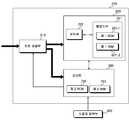
도 2는 본 발명의 일실시예에 따른 전원제어장치에 관한 구성도에 관한 도면이다.2 is a diagram of a configuration of a power supply control apparatus according to an embodiment of the present invention.
도 1 및 도 2를 참조하면, 상기 전원제어장치(200)는 전원공급부(210), 부팅처리부(220), 마이컴(230) 및 사용자 입력부(300)를 포함할 수 있다.1 and 2, the
상기 전원공급부(210)는 입력되는 교류(alternating current; AC) 전원을 직류(direct current; DC) 전원으로 변환하고, 상기 직류(DC) 전원을 상기 부팅처리부(220) 및 마이컴(230) 등으로 공급할 수 있다.The
상기 전원공급부(210)는 정류부, 스위칭부, 전력효율보정부 등을 포함할 수 있다.The
상기 정류부는 입력되는 교류(AC) 전원을 직류 전원(DC)으로 전환한다.The rectifier converts input AC power into DC power.
상기 직류(DC) 전원이 상기 부팅처리부(220) 및 마이컴(230) 등으로 공급될 수 있도록, 상기 스위칭부는 상기 정류부와 상기 부팅처리부(220), 마이컴(230) 등을 연결할 수 있다. 상기 스위칭부는 상기 마이컴(130)에 의해서 제어되는 것이 바람직하지만, 상기 부팅처리부(120)에 의해서 제어될 수도 있다.The switching unit may connect the rectifying unit, the
상기 전력효율보정(Power Factor Correction; PFC)부는 전력 효율을 향상시키기 위해 전원 장치에 부가된 절전회로를 의미한다. 상기 전력효율보정부는 상기 정류부의 후단에 연결될 수 있다.The power factor correction unit (PFC) refers to a power saving circuit added to a power supply device to improve power efficiency. The power efficiency correction unit may be connected to a rear end of the rectifier.
교류(AC) 전원이 인가되면, 본 실시예에 따른 상기 스위칭부는 상기 정류부와 상기 부팅처리부(220)를 연결하고, 상기 정류부와 상기 마이컴(230)을 연결한다. 즉, 상기 스위칭부는 온(ON) 상태로 존재한다.When AC power is applied, the switching unit according to the present embodiment connects the rectifier and the
'마지막 전원 모드'가 대기 모드로 판단된 경우, 상기 마이컴(230)은 상기 부팅처리부(220)로 인가되는 전원을 차단하도록 상기 스위칭부를 제어한다. 즉, 상 기 스위칭부는 상기 정류부와 상기 부팅처리부(220)의 연결을 끊는다.When the 'last power mode' is determined as the standby mode, the
상기 전원제어장치(200)로 인가되는 교류(AC) 전원이 차단되었다가 다시 인가되면, 상기 전원공급부(210)는 변환된 직류(DC) 전원을 상기 부팅처리부(220) 및 상기 마이컴(230)으로 인가한다.When the AC power applied to the
또 다른 일 실시예에 따르면, 상기 전원제어장치(200)로 인가되는 교류(AC) 전원이 차단되었다가 다시 인가되면, 상기 전원공급부(210)는 변환된 직류(DC) 전원을 상기 마이컴(230)에만 인가한다. 상기 직류(DC) 전원이 인가된 후, 상기 마이컴(230)은 상기 부팅처리부(220)에 전원이 인가되도록 상기 전원공급부(210)를 제어할 수 있다.According to another embodiment, when the AC power applied to the
결국, 상기 전원제어장치(200)로 인가되는 교류(AC) 전원이 차단되었다가 다시 인가되면, 상기 부팅처리부(220) 및 상기 마이컴(230)에 순차적으로 또는 동시에 전원이 인가된다.As a result, when AC power applied to the
상기 부팅처리부(220)는 메모리부(221) 및 제어부(222)를 포함할 수 있다.The
상기 메모리부(221)는 부팅(BOOTING)에 필요한 정보, 운영체제(operating system; OS), 사용자 설정 정보, 부팅처리부(220)의 동작을 위해 필요한 정보 등을 저장할 수 있다.The
또한, 상기 메모리부(221)는 상태 정보 및 구동프로그램을 저장할 수 있다.In addition, the
구체적으로, 상기 메모리부(221)는 제 1 롬(ROM)(221-1) 및 제 1 램(RAM)(221-2)을 포함할 수 있다. 상기 제 1 롬(ROM)(221-1)은 상기 상태 정보, 상기 구동프로그램, 부팅(BOOTING)에 필요한 정보, 운영체제(operating system; OS) 등을 저장할 수 있다.In detail, the
상기 상태 정보, 상기 구동프로그램, 부팅(BOOTING)에 필요한 정보, 운영체제(operating system; OS) 등은 교류(AC) 전원이 차단된 경우에도 지워지지 않아야할 데이터들이기 때문에, 상기 구동프로그램, 부팅(BOOTING)에 필요한 정보, 운영체제(operating system; OS) 등은 상기 제 1 롬(ROM)에 저장되는 것이 바람직하다.Since the state information, the driving program, information necessary for booting, an operating system (OS), and the like are data that should not be erased even when AC power is cut off, the driving program, BOOTING The information required for an operating system, an operating system (OS), and the like are preferably stored in the first ROM.
상기 상태 정보는 교류(AC) 전원이 차단되기 직전에 영상 기기의 상태에 관한 것이다. 교류(AC) 전원이 인가된 경우, 상기 제어부(222)는 현재 영상 기기의 상태(상태 정보)를 상기 제 1 롬(ROM)에 저장하게 된다. 상기 제어부(222)는 일정한 시간 간격으로 상기 상태 정보를 저장할 수 있다. 따라서, 교류(AC) 전원이 차단된 경우에도, 상기 상태 정보는 지워지지 않게 되는 것이다.The state information relates to the state of the video device just before the AC power is cut off. When AC power is applied, the
구체적으로, 상기 제 1 램(RAM)(221-2)은 부팅처리부(220)의 동작을 위해 필요한 정보 등을 저장할 수 있다.In detail, the first RAM 221-2 may store information necessary for the operation of the
상기 제 1 롬(ROM)(221-1)은 MASK ROM, PROM, EPROM, EEPROM, FLASH ROM 등으로 구현될 수 있다. 상기 제 1 램(RAM)(221-2)은 DRMA, SDRAM, DDR RAM 등으로 구현될 수 있다.The first ROM 221-1 may be implemented as a MASK ROM, a PROM, an EPROM, an EEPROM, a FLASH ROM, or the like. The first RAM 221-2 may be implemented with DRMA, SDRAM, DDR RAM, or the like.
상기 전원공급부(210)로부터 전원이 인가되면, 상기 제어부(222)는 상기 제 1 롬(ROM)(221-1)에 저장된 부팅(BOOTING)에 필요한 정보를 이용하여 부팅을 실행한다.When power is supplied from the
상기 전원공급부(210)로부터 전원이 인가되면, 상기 제어부(222)는 상기 제 1 롬(ROM)(221-1)에 저장된 상기 상태 정보 및 상기 구동 프로그램을 상기 마이컴(230)으로 전송한다.When power is supplied from the
상기 제어부(222)는 상기 상태 정보 및 상기 구동 프로그램이 상기 마이컴(230)으로 다운로드(download) 되었는지 여부를 판단할 수 있다.The
상기 제어부(222)는 상기 판단 결과, 상기 상태 정보 및 상기 구동 프로그램이 다운로드 되지 않았다고 판단된 경우에만, 상기 상태 정보 및 상기 구동 프로그램을 상기 마이컴(230)으로 전송한다.The
상기 제어부(222)는 상기 상태 정보 및 상기 구동 프로그램을 하나의 파일로 결합하고, 상기 결합된 파일을 상기 마이컴(230)으로 전송할 수 있다. 또한, 상기 제어부(222)는 상기 상태 정보 및 상기 구동프로그램을 순차적으로 상기 마이컴(230)으로 전송할 수도 있다.The
상기 제어부(222)는 상기 상태 정보 및 상기 구동 프로그램이 상기 마이컴(230)으로 다운로드(download) 되었는지를 표시할 수 있는 플래그를 저장하기 위한 플래그 저장부(미도시)를 더 포함할 수 있다. 상기 제어부(222)는 상기 플래그 저장부에 저장된 플래그를 이용하여, 상기 상태 정보 및 상기 구동 프로그램이 상기 마이컴(230)으로 다운로드(download) 되었는지 여부를 판단할 수 있다. 예를 들면, 상기 제어부(222)는 상기 상태 정보 및 상기 구동 프로그램이 상기 마이컴(230)으로 다운로드된 경우, 다운로드가 이루어졌다는 플래그를 상기 플래그 저장부에 저장한다. 따라서, 상기 제어부(222)는 상기 플래그를 이용하여 상기 상태 정보 및 상기 구동 프로그램이 다운로드 되었는지 여부를 판단할 수 있다.The
상기 제어부(222)는 상기 마이컴(230)과 필요한 정보를 주고 받을 수 있다.The
상기 마이컴(230)은 전원 모드에 따라 상기 전원공급부(210)를 제어하여, 공급되는 전원의 경로를 변경할 수 있다. 상기 전원 모드는 대기(stand-by) 모드 및 정상(normal) 모드를 포함할 수 있다. 다만, 상기 모드들에 한정하는 것이 아니며, 다양한 모드를 생성할 수 있다. 상기 전원 모드에 관련된 설명은 도 1에서 자세히 설명했었는바, 이하에서는 생략하겠다.The
대기 모드인 경우, 상기 마이컴(230) 및 상기 사용자 입력부(300)에만 전원이 공급된다. 따라서, 사용자는 대기 모드인 경우에도, 상기 사용자 입력부(300)를 이용하여 영상 기기 등을 제어할 수 있다.In the standby mode, power is supplied only to the
상기 마이컴(230)은 제 2 램(RAM)(231)을 포함할 수 있다. 상기 마이컴(230)은 상기 부팅처리부(220)로부터 전송된 상기 상태 정보 및 상기 구동프로그램을 상기 제 2 램(RAM)(231)에 저장할 수 있다.The
상기 마이컴(230)은 상기 부팅처리부(220)로부터 전송된 상기 구동 프로그램을 실행하고, 상기 부팅처리부(220)로부터 전송된 상기 상태 정보를 이용하여 '마지막 전원 모드'를 판단할 수 있다.The
상기 마이컴(230)은 상기 판단된 '마지막 전원 모드'에 따라 상기 전원공급부(210)를 제어한다.The
예를 들면, 상기 '마지막 전원 모드'가 대기(stand-by) 모드인 경우, 상기 마이컴(230)은 상기 부팅처리부(220)로 인가되는 전원이 차단되도록 상기 전원공급 부(210)를 제어한다.For example, when the 'last power mode' is a standby mode, the
반면에, 상기 '마지막 전원 모드'가 정상 모드인 경우, 상기 마이컴(230)은 상기 부팅처리부(220)로 전원이 인가되도록 상기 전원공급부(110)를 제어한다.On the other hand, when the 'last power mode' is the normal mode, the
상기 '마지막 전원 모드'란 교류 전원이 차단되기 직전의 전원 모드를 의미한다. 예를 들면, 교류 전원이 차단되기 직전의 전원 모드가 대기 모드였다면, 상기 '마지막 전원 모드'는 대기 모드가 되는 것이다.The 'last power mode' means a power mode immediately before the AC power is cut off. For example, if the power supply mode immediately before the AC power is cut off is the standby mode, the 'last power mode' is the standby mode.
사용자 입력부(300)는 사용자가 원하는 제어 신호를 입력하기 위해 사용된다. 상기 사용자 입력부(300)는 키패드, 마우스, 터치 패드 등으로 구성될 수 있다. 상기 사용자 입력부(300)는 대표적으로 리모컨이 사용된다.The
상기 제어 신호는 상기 마이컴(230)으로 입력된다. 상기 마이컴(230)은 상기 제어 신호에 따라 전원제어장치를 제어한다.The control signal is input to the
사용자는 상기 사용자 입력부(300)를 이용하여 원하는 채널 선택, 예약 등을 수행할 수 있다.The user may perform a desired channel selection, reservation, etc. using the
이에 따라, 본 발명에 따른 전원제어장치는 생산 비용이 낮을 뿐만 아니라 크기의 소형화도 가능하다. 즉, 상기 전원제어장치는 도 1의 전원제어장치에 비해, 마이컴의 롬(ROM) 및 EEPROM이 필요 없게 된다.Accordingly, the power supply control apparatus according to the present invention is not only low in production cost but also small in size. That is, the power control device does not need a microcomputer ROM (ROM) and EEPROM as compared to the power control device of FIG.
도 3은 본 발명의 또 다른 일실시예에 따른 전원제어장치에 관한 구성도에 관한 도면이다.3 is a diagram of a configuration of a power supply control apparatus according to another embodiment of the present invention.
도 2 및 도 3을 참조하면, 상기 전원제어장치(200)는 전원공급부(210), 부팅처리부(220), 마이컴(230) 및 사용자 입력부(300)를 포함할 수 있다. 상기 부팅처리부(220)는 메모리부(221) 및 제어부를 포함할 수 있다. 상기 마이컴(230)은 제 2 램(RAM)(231) 및 제 2 롬(ROM)을 포함할 수 있다.2 and 3, the
본 실시예에 따른 상기 전원제어장치(200)와 도 2의 전원제어장치의 차이점을 중심으로 살펴보겠다. 상기 차이점을 제외하고는 본 실시예에 따른 상기 전원제어장치(200)와 도 2의 전원제어장치는 동일하다.The difference between the
도 2의 부팅처리부의 메모리부는 상태 정보 및 구동프로그램을 저장한다. 반면에, 본 실시예에 따른 상기 부팅처리부(220)의 메모리부(221)는 상태 정보만을 저장한다.The memory unit of the boot processor of FIG. 2 stores state information and a driving program. On the other hand, the
또한, 도 2의 마이컴은 램(RAM)만을 포함한다. 반면에, 본 실시예에 따른 마이컴(230)은 제 2 램(231) 및 제 2 롬(232)을 포함한다. 상기 제 2 롬(ROM)(232)은 구동프로그램을 저장할 수 있다.In addition, the microcomputer of FIG. 2 includes only RAM. On the other hand, the
본 실시예에 따르면, 상기 전원공급부(210)로부터 전원이 인가되면, 상기 제어부(222)는 상기 제 1 롬(ROM)(221-1)에 저장된 부팅(BOOTING)에 필요한 정보를 이용하여 부팅을 실행한다.According to the present embodiment, when power is applied from the
상기 전원공급부(210)로부터 전원이 인가되면, 상기 제어부(222)는 상기 제 1 롬(ROM)(221-1)에 저장된 상기 상태 정보를 상기 마이컴(230)으로 전송한다.When power is applied from the
상기 마이컴(230)은 상기 부팅처리부(220)로부터 전송된 상기 상태 정보를 상기 제 2 램(RAM)(231)에 저장할 수 있다.The
이에 따라, 본 발명에 따른 전원제어장치는 생산 비용이 낮을 뿐만 아니라 크기의 소형화도 가능하다. 즉, 상기 전원제어장치는 도 1의 전원제어장치에 비해, 마이컴의 EEPROM이 필요 없게 된다.Accordingly, the power supply control apparatus according to the present invention is not only low in production cost but also small in size. That is, the power control device does not require the microcomputer's EEPROM, compared to the power control device of FIG.
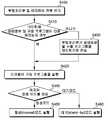
도 4는 본 발명의 일 실시예에 따른 전원제어방법에 관한 흐름도이다.4 is a flowchart illustrating a power control method according to an embodiment of the present invention.
도 2 및 도 4를 참조하면, 교류(AC) 전원이 전원공급부로 인가된다. 상기 전원공급부는 상기 교류(AC) 전원을 직류(DC) 전원으로 변환하고, 변환된 직류(DC) 전원을 부팅처리부와 마이컴으로 인가한다(S400).2 and 4, AC power is applied to the power supply unit. The power supply unit converts the AC power to DC power and applies the converted DC power to the boot processor and the microcomputer (S400).
상기 직류 전원이 인가되면, 상기 부팅처리부는 상기 마이컴에 상태 정보 및 구동프로그램이 다운로드 되었는지를 여부를 판단한다(S410).When the DC power is applied, the boot processor determines whether state information and a driving program have been downloaded to the microcomputer (S410).
상기 판단 결과, 상기 상태 정보 및 상기 구동프로그램이 다운로드된 경우, 상기 마이컴은 상기 구동프로그램을 실행한다(S420).As a result of the determination, when the state information and the driving program are downloaded, the microcomputer executes the driving program (S420).
반면에, 상기 판단 결과, 상기 상태 정보 및 상기 구동프로그램이 다운로드 되지 않은 경우, 상기 부팅처리부는 상기 상태 정보 및 상기 구동프로그램을 상기 마이컴으로 전송한다(S430). 상기 마이컴은 상기 부팅처리부로부터 전송된 상기 상태 정보 및 상기 구동프로그램을 저장한다. 상기 마이컴은 상기 구동프로그램을 실행한다(S420). 상기 구동프로그램은 상기 마이컴을 구동시키기 위해 필요한 프로그램이다.On the other hand, if the status information and the driving program are not downloaded as a result of the determination, the boot processor transmits the status information and the driving program to the microcomputer (S430). The microcomputer stores the state information and the driving program transmitted from the boot processor. The microcomputer executes the driving program (S420). The driving program is a program necessary for driving the microcomputer.
상기 마이컴은 상기 상태 정보를 이용하여 '마지막 전원 모드'를 판단한다(S440).The microcomputer determines the 'last power mode' using the state information (S440).
상기 판단 결과, 상기 '마지막 전원 모드'가 정상(normal) 모드인 경우, 상기 마이컴은 상기 부팅처리부와 상기 마이컴에 전원이 인가되도록 상기 전원공급부를 제어한다(S450).As a result of the determination, when the 'last power mode' is a normal mode, the microcomputer controls the power supply unit to supply power to the boot processor and the microcomputer (S450).
상기 판단 결과, 상기 '마지막 전원 모드'가 대기(stand-by) 모드인 경우, 상기 마이컴은 상기 부팅처리부로 인가되는 전원을 차단되도록 상기 전원공급부를 제어한다(S460).As a result of the determination, when the 'last power mode' is a stand-by mode, the microcomputer controls the power supply unit to cut off power applied to the boot processor (S460).
도 5는 도 4의 상태 정보 및 구동 프로그램을 전송하는 단계(S430)를 구체화한 도면이다.FIG. 5 is a diagram illustrating a step S430 of transmitting the state information and the driving program of FIG. 4.
도 5를 참조하면, 부팅처리부는 메모리부로부터 상태 정보 및 구동프로그램을 읽어온다(S500).Referring to FIG. 5, the boot processor reads state information and a driving program from a memory unit (S500).
상기 부팅처리부는 상기 구동프로그램에 상기 상태 정보를 결합한다(S510). 상기 구동프로그램의 포맷 중 남는 저장공간에 상기 상태 정보가 결합 될 수도 있다.The boot processor combines the state information with the driving program (S510). The state information may be combined in the remaining storage space of the drive program.
상기 부팅처리부는 상기 결합된 구동프로그램을 마이컴으로 전송한다(S520).The boot processor transmits the combined driving program to the microcomputer (S520).
또 다른 일실시예로, 상기 부팅처리부는 상기 상태 정보 및 구동프로그램을 순차적으로 마이컴으로 전송할 수 있다. 예를 들면, 상기 부팅처리부는 상기 구동 프로그램을 상기 마이컴으로 전송한 후에, 상기 상태 정보를 상기 마이컴으로 전송할 수도 있다.In another embodiment, the boot processor may sequentially transmit the state information and the driving program to the microcomputer. For example, the boot processor may transmit the state information to the microcomputer after transmitting the driving program to the microcomputer.
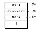
도 6은 본 발명의 일실시예에 따른 부팅처리부의 메모리부에 저장되는 상태 정보의 구체적인 내용을 표시한 도면이다.6 is a view showing specific contents of state information stored in a memory unit of a boot processor according to an exemplary embodiment of the present invention.
도 6을 참조하면, 상기 상태 정보는 사용자가 시청하던 채널 정보, '마지막 전원 모드' 정보, 볼륨 정보 등을 포함할 수 있다.Referring to FIG. 6, the state information may include channel information viewed by the user, 'last power mode' information, volume information, and the like.
상기 상태 정보란 사용자가 시청하고 있던 채널 정보(600), 마지막 전원 모드(대기 모드, 정상 모드 등) 정보(610), 볼륨 정보(620) 등을 의미한다.The state information refers to channel
상기 채널 정보(600)는 교류 전원이 차단되기 직전에 사용자가 시청하고 있던 채널이 14번이라는 것을 보여주고 있다.The
상기 마지막 전원 모드 정보(610)는 교류 전원이 차단되기 직전에 정상(normal) 모드였다는 것을 보여주고 있다.The last
상기 볼륨 정보(620)는 교류 전원이 차단되기 직전에 볼륨의 크기가 15였다는 것을 보여주고 있다.The
즉, 상기 상태 정보는 교류 전원이 차단되기 직전의 상태를 표시할 수 있는 것이다.That is, the state information can indicate the state immediately before the AC power is cut off.
본 발명의 기술 사상은 상기 바람직한 실시예에 따라 구체적으로 기술되었으나, 상기한 실시예는 그 설명을 위한 것이며, 그 제한을 위한 것이 아님을 주의하 여야 한다. 또한 본 발명의 기술분야의 통상의 전문가라면 본 발명의 기술사상의 범위에서 다양한 실시예가 가능함을 이해할 수 있을 것이다.Although the technical spirit of the present invention has been described in detail according to the above-described preferred embodiment, it should be noted that the above-described embodiment is for the purpose of description and not of limitation. In addition, those skilled in the art will understand that various embodiments are possible within the scope of the technical idea of the present invention.
도 1은 전원제어장치의 일실시예에 따른 구성도.1 is a configuration diagram according to an embodiment of a power supply control device.
도 2는 본 발명의 일실시예에 따른 전원제어장치에 관한 구성도.2 is a block diagram of a power supply control apparatus according to an embodiment of the present invention.
도 3은 본 발명의 또 다른 일실시예에 따른 전원제어장치에 관한 구성도.3 is a configuration of a power control apparatus according to another embodiment of the present invention.
도 4는 본 발명의 일실시예에 따른 전원제어방법에 관한 흐름도.4 is a flowchart illustrating a power control method according to an embodiment of the present invention.
도 5는 도 4의 상태 정보 및 구동 프로그램을 전송하는 단계(S430)를 구체화한 도면.FIG. 5 is a diagram illustrating a step S430 of transmitting the state information and the driving program of FIG. 4. FIG.
도 6은 본 발명의 일실시예에 따른 부팅처리부의 메모리부에 저장되는 상태 정보의 구체적인 내용을 표시한 도면.6 is a view showing specific contents of state information stored in a memory unit of a boot processing unit according to an embodiment of the present invention;
Claims (12)
Translated fromKoreanPriority Applications (1)
| Application Number | Priority Date | Filing Date | Title |
|---|---|---|---|
| KR1020090011267AKR20100092082A (en) | 2009-02-12 | 2009-02-12 | Apparatus for controlling power and method using the apparatus |
Applications Claiming Priority (1)
| Application Number | Priority Date | Filing Date | Title |
|---|---|---|---|
| KR1020090011267AKR20100092082A (en) | 2009-02-12 | 2009-02-12 | Apparatus for controlling power and method using the apparatus |
Publications (1)
| Publication Number | Publication Date |
|---|---|
| KR20100092082Atrue KR20100092082A (en) | 2010-08-20 |
Family
ID=42757027
Family Applications (1)
| Application Number | Title | Priority Date | Filing Date |
|---|---|---|---|
| KR1020090011267ACeasedKR20100092082A (en) | 2009-02-12 | 2009-02-12 | Apparatus for controlling power and method using the apparatus |
Country Status (1)
| Country | Link |
|---|---|
| KR (1) | KR20100092082A (en) |
- 2009
- 2009-02-12KRKR1020090011267Apatent/KR20100092082A/ennot_activeCeased
Similar Documents
| Publication | Publication Date | Title |
|---|---|---|
| CN1980320B (en) | Method for controlling power supply of digital television and digital television using the method | |
| US8860890B2 (en) | Electronic device and control method thereof | |
| US7145609B2 (en) | Method and apparatus of processing input signals of display appliance | |
| US7558977B2 (en) | Device and method for power management in a display device | |
| KR100600680B1 (en) | Electronic device and power control method | |
| US9625968B2 (en) | Method for operating multiple standby states and broadcast receiving apparatus using the same | |
| EP2465257B1 (en) | Image reproducing apparatus and method | |
| JP2005191815A (en) | Television broadcast receiving device | |
| US20140139741A1 (en) | Electronic device and power control method | |
| JP2013152573A (en) | Control method for information processing apparatus, control program for information processing apparatus, and information processing apparatus | |
| US7779283B2 (en) | Computer and method for realizing household appliance application with low power consumption | |
| US8253857B2 (en) | Broadcasting receiving apparatus | |
| CN101192170A (en) | Information processing device and power control method for information processing device | |
| KR20100092082A (en) | Apparatus for controlling power and method using the apparatus | |
| JPWO2009016719A1 (en) | Automatic start setting device, method and program | |
| JP2014126888A (en) | Information processor, display control method and display control program | |
| JP2005286634A (en) | External device control apparatus and external device control method | |
| JP2011061564A (en) | Remote control device, av device, and remote control system comprising them | |
| KR101264155B1 (en) | Broadcast Receiving Apparatus with Multiple Standby Mode and Power Control Method thereof | |
| JP2007166481A (en) | Computer apparatus and information output method | |
| JPWO2011064925A1 (en) | Content output control apparatus and content output control method | |
| JP2007282068A (en) | Personal computer with TV function | |
| JP2010062708A (en) | Digital broadcast receiver | |
| KR101744887B1 (en) | method of reducing power consumption of consumer electronic devices based on non-active time period management | |
| KR20120072180A (en) | Display apparatus and method for drive controlling thereof |
Legal Events
| Date | Code | Title | Description |
|---|---|---|---|
| PA0109 | Patent application | Patent event code:PA01091R01D Comment text:Patent Application Patent event date:20090212 | |
| PG1501 | Laying open of application | ||
| A201 | Request for examination | ||
| PA0201 | Request for examination | Patent event code:PA02012R01D Patent event date:20140124 Comment text:Request for Examination of Application Patent event code:PA02011R01I Patent event date:20090212 Comment text:Patent Application | |
| E902 | Notification of reason for refusal | ||
| PE0902 | Notice of grounds for rejection | Comment text:Notification of reason for refusal Patent event date:20141030 Patent event code:PE09021S01D | |
| E601 | Decision to refuse application | ||
| PE0601 | Decision on rejection of patent | Patent event date:20150112 Comment text:Decision to Refuse Application Patent event code:PE06012S01D Patent event date:20141030 Comment text:Notification of reason for refusal Patent event code:PE06011S01I |