KR20100091876A - Ue behavior for multi-antenna transmission - Google Patents
Ue behavior for multi-antenna transmissionDownload PDFInfo
- Publication number
- KR20100091876A KR20100091876AKR1020090077225AKR20090077225AKR20100091876AKR 20100091876 AKR20100091876 AKR 20100091876AKR 1020090077225 AKR1020090077225 AKR 1020090077225AKR 20090077225 AKR20090077225 AKR 20090077225AKR 20100091876 AKR20100091876 AKR 20100091876A
- Authority
- KR
- South Korea
- Prior art keywords
- antenna
- resources
- antenna transmission
- transmission mode
- uplink
- Prior art date
- Legal status (The legal status is an assumption and is not a legal conclusion. Google has not performed a legal analysis and makes no representation as to the accuracy of the status listed.)
- Pending
Links
Images


Classifications
- H—ELECTRICITY
- H04—ELECTRIC COMMUNICATION TECHNIQUE
- H04B—TRANSMISSION
- H04B7/00—Radio transmission systems, i.e. using radiation field
- H04B7/02—Diversity systems; Multi-antenna system, i.e. transmission or reception using multiple antennas
- H—ELECTRICITY
- H04—ELECTRIC COMMUNICATION TECHNIQUE
- H04B—TRANSMISSION
- H04B7/00—Radio transmission systems, i.e. using radiation field
- H04B7/02—Diversity systems; Multi-antenna system, i.e. transmission or reception using multiple antennas
- H04B7/04—Diversity systems; Multi-antenna system, i.e. transmission or reception using multiple antennas using two or more spaced independent antennas
- H04B7/06—Diversity systems; Multi-antenna system, i.e. transmission or reception using multiple antennas using two or more spaced independent antennas at the transmitting station
- H04B7/0686—Hybrid systems, i.e. switching and simultaneous transmission
- H04B7/0689—Hybrid systems, i.e. switching and simultaneous transmission using different transmission schemes, at least one of them being a diversity transmission scheme
- H—ELECTRICITY
- H04—ELECTRIC COMMUNICATION TECHNIQUE
- H04B—TRANSMISSION
- H04B7/00—Radio transmission systems, i.e. using radiation field
- H04B7/02—Diversity systems; Multi-antenna system, i.e. transmission or reception using multiple antennas
- H04B7/04—Diversity systems; Multi-antenna system, i.e. transmission or reception using multiple antennas using two or more spaced independent antennas
- H04B7/06—Diversity systems; Multi-antenna system, i.e. transmission or reception using multiple antennas using two or more spaced independent antennas at the transmitting station
- H04B7/0686—Hybrid systems, i.e. switching and simultaneous transmission
- H—ELECTRICITY
- H04—ELECTRIC COMMUNICATION TECHNIQUE
- H04L—TRANSMISSION OF DIGITAL INFORMATION, e.g. TELEGRAPHIC COMMUNICATION
- H04L27/00—Modulated-carrier systems
- H04L27/26—Systems using multi-frequency codes
- H04L27/2601—Multicarrier modulation systems
- H04L27/2602—Signal structure
- H04L27/261—Details of reference signals
- H04L27/2613—Structure of the reference signals
- H—ELECTRICITY
- H04—ELECTRIC COMMUNICATION TECHNIQUE
- H04L—TRANSMISSION OF DIGITAL INFORMATION, e.g. TELEGRAPHIC COMMUNICATION
- H04L5/00—Arrangements affording multiple use of the transmission path
- H04L5/003—Arrangements for allocating sub-channels of the transmission path
Landscapes
- Engineering & Computer Science (AREA)
- Signal Processing (AREA)
- Computer Networks & Wireless Communication (AREA)
- Mobile Radio Communication Systems (AREA)
- Radio Transmission System (AREA)
Abstract
Translated fromKoreanDescription
Translated fromKorean본 발명은 무선 통신 시스템에 관한 것이다. 본 발명은 SC-FDMA(Single Carrier-Frequency Division Multiple Access), MC-FDMA(Multi Carrier-Frequency Division Multiple Access) 및 OFDMA(Orthogonal Frequency Division Multiple Access) 중에서 적어도 하나를 지원하는 무선 통신 시스템에 관한 것이다. 구체적으로, 본 발명은 무선 통신 시스템에서 다중안테나 전송을 위한 단말 동작 및 이를 위한 장치에 관한 것이다.The present invention relates to a wireless communication system. The present invention relates to a wireless communication system supporting at least one of Single Carrier-Frequency Division Multiple Access (SC-FDMA), Multi Carrier-Frequency Division Multiple Access (MC-FDMA), and Orthogonal Frequency Division Multiple Access (OFDMA). Specifically, the present invention relates to a terminal operation for multi-antenna transmission in a wireless communication system and an apparatus therefor.
WCDMA(Wideband Code Division Multiple Access) 무선 접속(radio access) 기술을 기반으로 하는 3GPP(3rd Generation Partnership Project) 무선 통신 시스템은 전세계에서 광범위하게 전개되고 있다. WCDMA의 첫 번째 진화(evolution) 단계로 정의할 수 있는 HSDPA(High Speed Downlink Packet Access)는 중기적인(mid-term) 미래에서 높은 경쟁력을 가지는 무선 접속 기술을 3GPP에 제공한다. 장기적인 미래에서 높은 경쟁력을 제공하기 위한 것으로서 E-UMTS(Evolved-Universal Mobile Telecommunications System)가 있다.3rd Generation Partnership Project (3GPP) wireless communication systems based on Wideband Code Division Multiple Access (WCDMA) radio access technology are widely deployed around the world. High Speed Downlink Packet Access (HSDPA), which can be defined as the first evolution of WCDMA, provides 3GPP with a highly competitive wireless access technology in the mid-term future. Evolved-Universal Mobile Telecommunications System (E-UMTS) is to provide high competitiveness in the long term future.
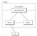
도 1은 E-UMTS의 네트워크(Network) 구조를 나타낸다. E-UMTS 시스템은 WCDMA UMTS 시스템에서 진화한 시스템으로 3GPP(3rd Generation Partnership Project)에서 표준화 작업을 진행하고 있다. E-UMTS는 LTE(Long Term Evolution) 시스템이라 불리기도 한다. UMTS 및 E-UMTS의 기술 규격(technical specification)의 상세한 내용은 "3rd Generation Partnership Project; Technical Specification Group Radio Access Network"의 Release 7과 Release 8을 참조할 수 있다.1 shows a network structure of an E-UMTS. The E-UMTS system is an evolution from the WCDMA UMTS system and is being standardized by the 3rd Generation Partnership Project (3GPP). E-UMTS is also called a Long Term Evolution (LTE) system. For details of technical specifications of UMTS and E-UMTS, refer to Release 7 and
도 1을 참조하면, E-UMTS는 단말(User Equipment; UE), 기지국(eNode B; eNB), 네트워크(E-UTRAN)의 종단에 위치하여 외부 네트워크와 연결되는 접속 게이트웨이(Access Gateway; AG)을 포함한다. 기지국은 브로드캐스트(Broadcast) 서비스, 멀티캐스트(Multicast) 서비스 및/또는 유니캐스트(Unicast) 서비스를 위해 다중 데이터 스트림(Multiple Data Stream)을 동시 송신할 수 있다. 하나의 기지국에는 하나 이상의 셀(cell)이 존재한다. 기지국 간에는 사용자 트래픽 또는 제어 트래픽 전송을 위한 인터페이스가 사용될 수 있다. CN(Core Network)은 AG와 단말의 사용자 등록 등을 위한 네트워크 노드 등으로 구성될 수 있다. E-UTRAN과 CN을 구분하기 위한 인터페이스가 사용될 수 있다. AG는 TA(Tracking Area) 단위로 단말의 이동성을 관리한다. TA는 복수의 셀들로 구성되며, 단말은 특정 TA에서 다른 TA로 이동할 경우, AG에게 자신이 위치한 TA가 변경되었음을 알려준다.Referring to FIG. 1, an E-UMTS is located at an end of a user equipment (UE), a base station (eNode B; eNB), and a network (E-UTRAN) and connected to an external network (Access Gateway; AG). It includes. The base station may simultaneously transmit multiple data streams for broadcast service, multicast service, and / or unicast service. One or more cells exist in one base station. An interface for transmitting user traffic or control traffic may be used between base stations. CN (Core Network) may be composed of a network node for the user registration of the AG and the terminal. An interface for distinguishing between E-UTRAN and CN may be used. AG manages the mobility of the terminal in units of a tracking area (TA). The TA is composed of a plurality of cells, and when the UE moves from one TA to another, the AG notifies the AG of the change of the TA.
무선 통신 기술은 WCDMA를 기반으로 LTE까지 개발되어 왔지만, 사용자와 사 업자의 요구와 기대는 지속적으로 증가하고 있다. 또한, 다른 무선 접속 기술이 계속 개발되고 있으므로 향후 경쟁력을 가지기 위해서는 새로운 기술 진화가 요구된다. 비트당 비용 감소, 서비스 가용성 증대, 융통성 있는 주파수 밴드의 사용, 단순구조와 개방형 인터페이스, 단말의 적절한 파워 소모 등이 요구된다. 이와 관련하여, 3GPP는 LTE의 후속 기술에 대한 표준화 작업을 진행하고 있다. 본 명세서에서는 상기 기술을 "LTE-Advanced" 또는 "LTE-A"라고 지칭한다.Wireless communication technology has been developed based on WCDMA to LTE, but the demands and expectations of users and businesses are continuously increasing. In addition, as other radio access technologies continue to be developed, new technological evolution is required to be competitive in the future. Reduced cost per bit, increased service availability, the use of flexible frequency bands, simple structure and open interface, and adequate power consumption of the terminal are required. In this regard, 3GPP is working on standardization of the following LTE technology. In the present specification, the above technique is referred to as "LTE-Advanced" or "LTE-A".
한편, LTE의 경우 하향링크로 MIMO(Multiple-Input Multiple-Output)가 적용되어 공간 다중화(spatial multiplexing)가 사용되었으나 상향링크로는 단말기의 전력증폭기의 효율성 및 안테나 배치 등의 문제 때문에 공간 다중화가 고려되지 않았다. 그러나, 보다 고속 통신의 요구와 주파수 자원 활용의 극대화를 위해서 LTE-A는 상향링크에서 MIMO(Multiple Input Multiple Output)를 이용한 공간 다중화를 요구하고 있다. 구체적으로, LTE-A는 상향링크 전송에서 최대 4개 계층(layer)까지 공간 다중화를 요구하고 있다. 또한, LTE-A는 상향링크 전송에서 단일 사용자에 의한 다중화의 경우 콤포넌트 반송파(component carrier) 당 하나의 서브프레임을 통해 최대 2개의 전송 블록을 전송하도록 요구하고 있다. 콤포넌트 반송파는 주파수 집성(carrier aggregation)에 사용되는 기본 주파수 블록으로서, 주파수 집성은 복수의 주파수 블록을 논리적으로 합쳐 광대역을 지원하는 기술을 의미한다. LTE-A는 광대역을 위해 주파수 집성 기술을 사용하도록 하고 있다.In the case of LTE, multiplexing is used because multiple-input multiple-output (MIMO) is applied as a downlink, but spatial multiplexing is considered as an uplink due to problems such as efficiency of the power amplifier of the terminal and antenna arrangement. It wasn't. However, LTE-A requires spatial multiplexing using multiple input multiple output (MIMO) in uplink in order to maximize the demand for higher speed communication and maximize utilization of frequency resources. Specifically, LTE-A requires spatial multiplexing up to four layers in uplink transmission. In addition, LTE-A requires up to two transport blocks to be transmitted through one subframe per component carrier in case of multiplexing by a single user in uplink transmission. The component carrier is a basic frequency block used for carrier aggregation, and frequency aggregation refers to a technology for supporting wideband by logically combining a plurality of frequency blocks. LTE-A requires the use of frequency aggregation technology for broadband.
본 발명은 상기한 바와 같은 종래기술의 문제점을 해결하기 위해 안출된 것으로서, 본 발명의 목적은 무선 통신 시스템에서 다중안테나를 통해 상향링크 전송 을 수행하는 방법 및 이를 위한 장치를 제공하는 것이다.The present invention has been made to solve the problems of the prior art as described above, it is an object of the present invention to provide a method and apparatus for performing uplink transmission through multiple antennas in a wireless communication system.
본 발명의 다른 목적은 다중안테나를 통한 상향링크 전송과 관련된 시그널링 방법 및 이를 위한 장치를 제공하는 것이다.Another object of the present invention is to provide a signaling method related to uplink transmission through multiple antennas and an apparatus therefor.
본 발명의 또 다른 목적은 SC-FDMA를 이용한 상향링크 전송시에 다중안테나 전송 모드를 결정하는 방법 및 이를 위한 장치를 제공하는 것이다.Another object of the present invention is to provide a method and apparatus for determining a multi-antenna transmission mode in uplink transmission using SC-FDMA.
본 발명에서 이루고자 하는 기술적 과제들은 이상에서 언급한 기술적 과제들로 제한되지 않으며, 언급하지 않은 또 다른 기술적 과제들은 아래의 기재로부터 본 발명이 속하는 기술분야에서 통상의 지식을 가진 자에게 명확하게 이해될 수 있을 것이다.Technical problems to be achieved in the present invention are not limited to the above-mentioned technical problems, and other technical problems not mentioned above will be clearly understood by those skilled in the art from the following description. Could be.
본 발명의 일 양상으로, 무선 통신 시스템에서 단말이 신호를 전송하는 방법에 있어서, 다중안테나 전송을 위한 설정 정보를 기지국으로부터 수신하는 단계; 상기 설정 정보에 따라 다중안테나 전송 모드를 설정하는 단계; 및 복수의 SC-FDMA(Single Carrier Frequency Division Multiple Access) 심볼을 가지는 상향링크 채널을 다중안테나를 통해 기지국으로 전송하는 단계를 포함하는 신호 전송 방법이 제공된다.In one aspect of the present invention, a method for transmitting a signal by a terminal in a wireless communication system, the method comprising: receiving configuration information for multi-antenna transmission from a base station; Setting a multiple antenna transmission mode according to the configuration information; And transmitting an uplink channel having a plurality of single carrier frequency division multiple access (SC-FDMA) symbols to a base station through multiple antennas.
본 발명의 다른 양상으로, 다중안테나; 기지국으로부터 다중안테나 전송을 위한 설정 정보를 수신하도록 구성되고, 설정된 다중안테나 전송 모드에 따라 복수의 SC-FDMA(Single Carrier Frequency Division Multiple Access) 심볼을 가지는 상향링크 채널을 다중안테나를 통해 기지국으로 전송하도록 구성된 무선 주파 수(Radio Frequency; RF) 모듈; 및 상기 설정 정보에 따라 다중안테나 전송 모드를 설정하도록 구성된 프로세서를 포함하는 단말이 제공된다.In another aspect of the invention, multiple antennas; Configured to receive configuration information for multi-antenna transmission from the base station, and to transmit an uplink channel having a plurality of single carrier frequency division multiple access (SC-FDMA) symbols to the base station through the multi-antenna according to the set multi-antenna transmission mode. A configured radio frequency (RF) module; And a processor configured to set a multi-antenna transmission mode according to the configuration information.
여기에서, 상기 설정 정보는 MIMO(Multiple Input Mulitiple Output) 전송 기법을 사용할지 여부를 지시하는 1-비트 정보일 수 있다.Here, the configuration information may be 1-bit information indicating whether to use a multiple input mulitiple output (MIMO) transmission scheme.
여기에서, 상기 설정 정보는 채널 추정이 요구되는 안테나의 총 개수를 지시할 수 있다.Here, the configuration information may indicate the total number of antennas for which channel estimation is required.
여기에서, 상기 설정 정보는 상향링크 스케줄링 정보에 포함될 수 있다.Here, the configuration information may be included in uplink scheduling information.
여기에서, 상기 상향링크 채널은 OSRT(Orthogonal Space Resource Transmission) 전송 기법을 이용하여 전송될 수 있다.Here, the uplink channel may be transmitted using an orthogonal space resource transmission (OSRT) transmission scheme.
본 발명의 또 다른 양상으로, 무선 통신 시스템에서 단말이 신호를 전송하는 방법에 있어서, 복수의 SC-FDMA(Single Carrier Frequency Division Multiple Access) 심볼을 가지는 상향링크 채널과 관련된 하나 이상의 자원을 확인하는 단계; 상기 하나 이상의 자원에 기초해 다중안테나 전송 모드를 설정하는 단계; 및 상기 상향링크 채널을 다중안테나를 통해 기지국으로 전송하는 포함하는 신호 전송 방법이 제공된다.In another aspect of the present invention, in a method for transmitting a signal by a terminal in a wireless communication system, identifying at least one resource associated with an uplink channel having a plurality of single carrier frequency division multiple access (SC-FDMA) symbols ; Setting a multiple antenna transmission mode based on the one or more resources; And a signal transmission method for transmitting the uplink channel to a base station through multiple antennas.
본 발명의 또 다른 양상으로, 다중안테나; 설정된 다중안테나 전송 모드에 따라 복수의 SC-FDMA(Single Carrier Frequency Division Multiple Access) 심볼을 가지는 상향링크 채널을 다중안테나를 통해 기지국으로 전송하도록 구성된 무선 주파수(Radio Frequency; RF) 모듈; 및 상기 상향링크 채널과 관련된 하나 이상의 자원을 확인하도록 구성되고, 상기 하나 이상의 자원에 기초해 다중안테나 전송 모드 를 설정하도록 구성된 프로세서를 포함하는 단말이 제공된다.In another aspect of the invention, multiple antennas; A radio frequency (RF) module configured to transmit an uplink channel having a plurality of single carrier frequency division multiple access (SC-FDMA) symbols to a base station through multiple antennas according to a configured multiple antenna transmission mode; And a processor configured to identify one or more resources associated with the uplink channel and configured to set a multi-antenna transmission mode based on the one or more resources.
여기에서, 상기 상향링크 채널은 PUCCH(Physical Uplink Control CHannel)일 수 있다. 또한, 상기 상향링크 채널은 PUSCH(Physical Uplink Shared CHannel)이고, 상기 하나 이상의 자원은 기준 신호에 관한 것일 수 있다.Here, the uplink channel may be a physical uplink control channel (PUCCH). The uplink channel may be a physical uplink shared channel (PUSCH), and the one or more resources may be related to a reference signal.
여기에서, 상기 하나 이상의 자원은 순환 쉬프트(Cyclic Shift; CS), 직교 커버링(Orthogonal Covering; OC), 자원블록(Resource Block; RB) 또는 이들의 임의의 조합을 포함할 수 있다.Here, the one or more resources may include Cyclic Shift (CS), Orthogonal Covering (OC), Resource Block (RB), or any combination thereof.
여기에서, 상기 다중안테나 전송 모드는 상기 하나 이상의 자원의 총 개수에 기초하여 결정될 수 있다.Here, the multi-antenna transmission mode may be determined based on the total number of the one or more resources.
여기에서, 상기 다중안테나 전송 모드는 상기 하나 이상의 자원 중에서 소정 관계에 있는 자원의 개수에 기초하여 결정될 수 있다. 이 경우, 상기 하나 이상의 자원은 복수의 필드를 이용하여 지시되고, 상기 다중안테나 전송 모드는 각 필드간의 동일성 여부에 기초하여 결정될 수 있다. 또한, 상기 하나 이상의 자원은 안테나 별로 지시되고, 상기 다중안테나 전송 모드는 각 자원간의 동일성 여부에 기초하여 결정될 수 있다.Here, the multi-antenna transmission mode may be determined based on the number of resources having a predetermined relationship among the one or more resources. In this case, the one or more resources are indicated using a plurality of fields, and the multi-antenna transmission mode may be determined based on whether or not each field is identical. In addition, the one or more resources are indicated for each antenna, and the multi-antenna transmission mode may be determined based on whether each resource is identical.
본 발명의 실시예들에 따르면 다음과 같은 효과가 있다.According to the embodiments of the present invention, the following effects are obtained.
첫째, 무선 통신 시스템에서 다중안테나를 통해 상향링크 전송을 수행하는 방법 및 이를 위한 장치를 제공할 수 있다.First, a method and apparatus for performing uplink transmission through multiple antennas in a wireless communication system can be provided.
둘째, 다중안테나를 통한 상향링크 전송과 관련된 시그널링(signaling) 방법 및 이를 위한 장치를 제공할 수 있다.Second, a signaling method related to uplink transmission through multiple antennas and an apparatus therefor may be provided.
셋째, SC-FDMA를 상향링크 전송시에 다중안테나 전송 모드를 결정하는 방법 및 이를 위한 장치를 제공하는 것이다.Third, there is provided a method and apparatus for determining a multi-antenna transmission mode for uplink transmission of SC-FDMA.
본 발명에서 얻을 수 있는 효과는 이상에서 언급한 효과들로 제한되지 않으며, 언급하지 않은 또 다른 효과들은 아래의 기재로부터 본 발명이 속하는 기술분야에서 통상의 지식을 가진 자에게 명확하게 이해될 수 있을 것이다.The effects obtainable in the present invention are not limited to the above-mentioned effects, and other effects not mentioned above may be clearly understood by those skilled in the art from the following description. will be.
첨부된 도면을 참조하여 설명되는 본 발명의 바람직한 실시예들에 의해 본 발명의 구성, 작용 및 다른 특징들이 용이하게 이해될 수 있을 것이다. 이하에서 설명되는 실시예들은 본 발명의 기술적 특징이 3GPP 시스템에 적용된 예들이다. 그러나, 이는 예시로서 본 발명은 다중안테나를 갖는 어떤 통신 시스템에도 제한 없이 사용될 수 있다.The construction, operation, and other features of the present invention will be readily understood by the preferred embodiments of the present invention described with reference to the accompanying drawings. The embodiments described below are examples in which the technical features of the present invention are applied to a 3GPP system. However, as an example, the present invention can be used without limitation in any communication system having multiple antennas.
OFDMA는 직교 주파수 분할 다중화(Orthogonal Frequency Division Multiplexing; OFDM)를 이용한다. OFDM은 높은 전송률의 데이터 열을 낮은 전송률의 많은 데이터 열로 나누고 이들을 복수의 직교하는 부반송파를 사용하여 동시에 전송한다. OFDMA는 가용한 부반송파의 일부를 각 사용자에게 제공하여 다중 접속을 실현한다. OFDMA는 높은 스펙트럼 효율, 다중 경로 영향들에 대한 견고함 등의 바람직한 특성을 갖는다. 그러나, OFDMA의 가장 큰 단점은 높은 첨두 전력-대-평균 전력비(Peak to Average Power Ratio; PAPR)이다. 높은 PAPR은 부반송파들의 동상 부가로부터 발생한다. PAPR은 한 사용자가 신호를 송신하는 부반송파의 수가 증가 함에 따라 증가하며 95% 신뢰 수준에서 PAPR은 약 8dB 이내로 수렴한다. 무선 통신 시스템에서 높은 PAPR은 바람직하지 못하며 시스템 성능을 저하시킬 수 있다. 구체적으로, OFDMA 심볼에서 큰 첨두 전력은 전력 증폭 과정에서 비선형 영역에서 동작하거나 소정 값으로 고정(clip)될 수 있다. 따라서, 높은 첨두 전력은 신호 품질의 저하 및 신호 왜곡을 수반하고, 채널 추정, 데이터 검출 등에 영향을 미칠 수 있다. SC-FDMA는 OFDMA에서 관찰되는 높은 PAPR을 감소시키기 위해 제안된 기술이다. SC-FDMA가 OFDMA 방식과 다른 점은 IFFT(Inverse Fast Fourier Transform) 처리 이전에 DFT 프리코딩을 통해 데이터를 주파수 영역에 확산시키는 점에 있다. 이런 방식을 이용하여 송신 신호의 PAPR을 OFDMA 방식에 비해 크게 줄일 수 있다. 본 명세서에서 SC-FDMA는 DFT-s-OFDMA(DFT-Spread-OFDMA)와 혼용된다.OFDMA uses Orthogonal Frequency Division Multiplexing (OFDM). OFDM divides high-rate data strings into many low-rate data strings and transmits them simultaneously using a plurality of orthogonal subcarriers. OFDMA provides each user with a portion of the available subcarriers to realize multiple access. OFDMA has desirable characteristics such as high spectral efficiency, robustness to multipath effects, and the like. However, the biggest drawback of OFDMA is its high Peak to Average Power Ratio (PAPR). High PAPR results from in-phase addition of subcarriers. PAPR increases as the number of subcarriers a user sends signals increases, and at 95% confidence, PAPR converges to within about 8 dB. High PAPR in wireless communication systems is undesirable and can degrade system performance. In detail, a large peak power in an OFDMA symbol may be operated in a nonlinear region or clipped to a predetermined value in a power amplification process. Thus, high peak power involves degradation of signal quality and signal distortion, and can affect channel estimation, data detection, and the like. SC-FDMA is a proposed technique for reducing the high PAPR observed in OFDMA. SC-FDMA differs from OFDMA in that data is spread in the frequency domain through DFT precoding before IFFT (Inverse Fast Fourier Transform) processing. By using this method, the PAPR of the transmission signal can be significantly reduced compared to the OFDMA method. SC-FDMA is used interchangeably with DFT-s-OFDMA (DFT-Spread-OFDMA) herein.
도 2는 OFDMA 및 SC-FDMA를 위한 송신기 및 수신기의 블록도를 예시한다. 상향링크에서 송신기는 단말의 일부일 수 있고 수신기는 기지국의 일부일 수 있다. 하향링크에서 송신기는 기지국의 일부일 수 있고 수신기는 단말의 일부일 수 있다.2 illustrates a block diagram of a transmitter and a receiver for OFDMA and SC-FDMA. In uplink, a transmitter may be part of a terminal and a receiver may be part of a base station. In downlink, a transmitter may be part of a base station and a receiver may be part of a terminal.
도 2를 참조하면, OFDMA 송신기는 직/병렬 변환기(Serial to Parallel converter, 202), 부반송파 매핑(sub-carrier mapping) 모듈(206), M-포인트(point) IDFT 모듈(208), 순한전치(Cyclic prefix; CP) 부가 모듈(210), 병/직렬 변환기(Parallel to Serial converter, 212) 및 RF(Radio Frequency)/DAC(Digital to Analog Converter) 모듈(214)을 포함한다.Referring to FIG. 2, the OFDMA transmitter includes a serial to parallel converter (202), a
OFDMA 송신기에서 신호 처리 과정은 다음과 같다. 먼저, 비트 스트림(bit stream)이 데이터 심볼 시퀀스(data symbol sequence)로 변조된다. 비트 스트림은 매체접속제어(Medium Access Control; MAC) 계층으로부터 전달받은 데이터 블록에 채널 부호화(channel encoding), 인터리빙(interleaving), 스크램블링(scrambling) 등과 같은 다양한 신호 처리를 하여 얻어질 수 있다. 비트 스트림은 부호어(codeword)로 지칭되기도 하며 MAC 계층으로부터 받는 데이터 블록과 등가이다. MAC 계층으로부터 받는 데이터 블록은 전송 블록으로 지칭되기도 한다. 변조 방식은 이로 제한되는 것은 아니지만 BPSK(Binary Phase Shift Keying), QPSK(Quadrature Phase Shift Keying), n-QAM(Quadrature Amplitude Modulation)을 포함할 수 있다. 그 후, 직렬의 데이터 심볼 시퀀스는 N개씩 병렬로 변환된다(202). N개의 데이터 심볼은 전체 M개의 부반송파 중에서 할당받은 N개의 부반송파에 매핑(mapping)되고 남은 M-N개의 반송파는 0으로 패딩된다(206). 주파수 영역에 매핑된 데이터 심볼은 M-포인트 IDFT 처리를 통해 시간 영역 시퀀스로 변환된다(208). 그 후, 심볼간 간섭(Inter-Symbol Interference; ISI)과 반송파간 간섭(Inter-Carrier Interference; ICI)을 줄이기 위해서, 상기 시간 영역 시퀀스에 순환전치를 더하여 OFDMA 심볼을 생성한다(210). 생성된 OFDMA 심볼은 병렬에서 직렬로 변환된다(212). 그 후, OFDMA 심볼은 디지털-대-아날로그 변환, 주파수 상향변환 등의 과정을 거쳐 수신기로 전송된다(214). 다른 사용자는 남은 M-N개의 부반송파 중에서 가용한 부반송파를 할당받는다. 반면, OFDMA 수신기는 RF/ADC(Analog to Digital Converter) 모듈(216), 직/병렬 변환기(218), 순환전치 제거(Remove CP) 모듈(220), M-포인트 DFT 모듈(224), 부반송파 디매핑(demapping)/등화(equalization) 모듈(226), 병/직렬 변환기(228) 및 검출(detection) 모듈(230) 을 포함한다. OFDMA 수신기의 신호 처리 과정은 OFDMA 송신기의 역으로 구성된다.Signal processing in the OFDMA transmitter is as follows. First, a bit stream is modulated into a data symbol sequence. The bit stream may be obtained by performing various signal processing such as channel encoding, interleaving, scrambling, etc. on the data block received from the medium access control (MAC) layer. The bit stream is sometimes referred to as a codeword and is equivalent to a block of data received from the MAC layer. The data block received from the MAC layer is also called a transport block. The modulation scheme may include, but is not limited to, Binary Phase Shift Keying (BPSK), Quadrature Phase Shift Keying (QPSK), and Quadrature Amplitude Modulation (n-QAM). Thereafter, the serial data symbol sequences are converted N by N in parallel (202). The N data symbols are mapped to the allocated N subcarriers among the total M subcarriers, and the remaining M-N carriers are padded with zeros (206). Data symbols mapped to the frequency domain are converted to time domain sequences through M-point IDFT processing (208). Thereafter, in order to reduce inter-symbol interference (ISI) and inter-carrier interference (ICI), an OFDMA symbol is generated by adding a cyclic prefix to the time-domain sequence. The generated OFDMA symbols are converted 212 in parallel to serial. Thereafter, the OFDMA symbol is transmitted to the receiver through the process of digital-to-analog conversion, frequency upconversion, etc. (214). The other user is allocated available subcarriers among the remaining M-N subcarriers. On the other hand, the OFDMA receiver includes an RF / ADC (Analog to Digital Converter)
한편, SC-FDMA 송신기는 OFDMA 송신기와 비교하여 부반송파 매핑 모듈(206) 이전에 N-포인트 DFT 모듈(204)을 추가로 포함한다. SC-FDMA 송신기는 IDFT 처리 이전에 DFT를 통해 복수의 데이터를 주파수 영역에 확산시켜 송신 신호의 PAPR을 OFDMA 방식에 비해 크게 줄일 수 있다. SC-FDMA 수신기는 OFDMA 수신기와 비교하여 부반송파 디매핑 모듈(226) 이후에 N-포인트 IDFT 모듈(228)을 추가로 포함한다. SC-FDMA 수신기의 신호 처리 과정은 SC-FDMA 송신기의 역으로 구성된다.On the other hand, the SC-FDMA transmitter further includes an N-
도 2에서 예시한 모듈은 설명을 위한 것으로서, 송신기 및/또는 수신기는 필요한 모듈을 더 포함할 수 있고, 일부 모듈/기능은 생략되거나 서로 다른 모듈로 분리될 수 있으며, 둘 이상의 모듈이 하나의 모듈로 통합될 수 있다.The module illustrated in FIG. 2 is for illustrative purposes, and the transmitter and / or receiver may further include necessary modules, some modules / functions may be omitted, or may be separated into different modules, and two or more modules may be one module. It can be integrated into.
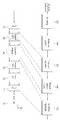
도 3은 LTE 시스템에 정의된 상향링크 송신기의 구조를 나타낸다. LTE 시스템은 상향링크 전송에 SC-FDMA를 사용하고 하향링크 전송에 OFDMA를 사용한다.3 shows a structure of an uplink transmitter defined in an LTE system. The LTE system uses SC-FDMA for uplink transmission and OFDMA for downlink transmission.
도 3을 참조하면, SC-FDMA 송신기는 스크램블링 모듈(Scrambling, 302), 변조 매퍼(Modulation mapper, 304), 변환 프리코더(Transform precoder, 306), 자원 요소 매퍼(Resource element mapper, 308) 및 SC-FDMA 신호 생성 모듈(310)을 포함한다. 신호 처리 과정은 다음과 같다. 스크램블링 모듈(302)은 단말의 특정 스크램블링 코드/시퀀스를 사용하여 비트 스트림을 스크램블링할 수 있다. 변조 매퍼(304)는 신호의 종류 및/또는 채널 상태에 따라 스크램블링된 신호를 BPSK, QPSK, 16 QAM 등의 방식을 이용하여 복소 심볼로 변조한다. 변조된 복소 심볼은 변환 프리코더(306)에 의해 처리된 후, 자원 요소 매퍼(308)에 입력된다. 자원 요소 매퍼(308)는 복소 심볼을 스케줄링된 부반송파에 매핑한다. 부반송파에 매핑된 신호는 SC-FDMA 신호 생성기(310)를 거쳐 상향링크로 전송될 수 있다.Referring to FIG. 3, the SC-FDMA transmitter includes a
참고로, 변환 프리코더(306)는 도 2의 N-포인트 DFT 모듈(204)에 대응한다. 자원 요소 매퍼(308)는 도 2의 부반송파 매핑 모듈(206)에 대응한다. SC-FDMA 신호 생성 모듈(310)은 도 2의 M-포인트 IDFT 모듈(206), CP 부가 모듈(210) 및 병/직렬 변환기(212)에 대응한다. 도 3에서 예시한 모듈은 설명을 위한 것으로서, SC-FDMA 송신기는 필요한 모듈을 더 포함할 수 있고, 일부 모듈/기능은 생략되거나 서로 다른 모듈로 분리될 수 있으며, 둘 이상의 모듈이 하나의 모듈로 통합될 수 있다.For reference, the
이하, 변환 프리코더(306)에서의 신호 처리 과정을 보다 구체적으로 설명한다. 변환 프리코더(306)로 입력되는 데이터 심볼 시퀀스는d(O), …,d(Msymb-1)로 표시되는 복소 심볼일 수 있다. 변환 프리코더(306)는 한번에 N개의 데이터 심볼을 처리하며, 데이터 심볼 시퀀스는Msymb/N 세트로 나눠진다. 각 세트는 최종적으로 SC-FDMA 심볼을 구성한다. 여기서, N은 스케줄링된 부반송파의 개수를 나타낸다. 변환 프리코더(306)로 입력된 데이터 심볼은 하기 수학식에 의해 처리될 수 있다.Hereinafter, the signal processing procedure in the

수학식 1의 과정은 DFT 프로세스에 해당하며, 변환 프리코더(306)에 의해D(O), …,D(Msymb-1)로 표시되는 주파수 영역 시퀀스가 생성된다. 주파수 영역 시퀀스의 각 값은 매핑되는 부반송파의 크기 및 위상을 결정한다.The process of
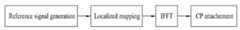
도 4는 SC-FDMA 송신기에서 기준 신호(Reference Signal; RS)를 생성하는 방법을 예시하는 블록도이다.4 is a block diagram illustrating a method of generating a reference signal (RS) in an SC-FDMA transmitter.
도 4를 참조하면, 기준 신호는 주파수 영역에서 바로 생성된다. 즉, 기준 신호는 DFT 프리코더를 거치지 않는다. 기준 신호는 직교 시퀀스, 준-직교 시퀀스 또는 상관 특성이 좋은 시퀀스를 이용하여 생성된다. 일 예로, 기준 신호는 컴퓨터-생성(computer-generated) 시퀀스, ZC(Zadoff-Chu), CAZAC(Constant amplitude zero autocorrelation waveform), PN(Pseudo-random Noise) 시퀀스 등을 포함할 수 있다. 그 후, 기준 신호는 주파수 영역 내에서 복수의 부반송파에 매핑된다. 기준 신호는 주파수 영역에서 연속적으로 또는 불연속적으로 매핑될 수 있다. 주파수 영역에 매핑된 매핑된 기준 신호는 IFFT를 거쳐서 시간 영역 신호로 변환된다. 시간 영역 신호는 순환전치(CP)가 부가된 뒤 수신단으로 전송된다.4, a reference signal is generated directly in the frequency domain. That is, the reference signal does not go through the DFT precoder. The reference signal is generated using an orthogonal sequence, a quasi-orthogonal sequence, or a sequence having good correlation characteristics. For example, the reference signal may include a computer-generated sequence, a Zadoff-Chu (ZC), a constant amplitude zero autocorrelation waveform (CAZAC), a pseudo-random noise (PN) sequence, and the like. Thereafter, the reference signal is mapped to a plurality of subcarriers in the frequency domain. The reference signal may be mapped continuously or discontinuously in the frequency domain. The mapped reference signal mapped in the frequency domain is converted into a time domain signal through an IFFT. The time domain signal is transmitted to the receiving end after the cyclic prefix CP is added.
도 5는 무선 프레임(radio frame)의 구조를 예시한다.5 illustrates a structure of a radio frame.
도 5를 참조하면, 무선 프레임은 10ms의 길이이고 10개의 서브프레임(subframe)을 포함한다. 각 서브프레임은 1ms의 길이이고 2개의 슬롯(slot)을 포함한다. 각 슬롯은 0.5ms의 길이를 가진다. 도면에서, Ts는 샘플링 시간을 나타내고, Ts=1/(15kHz×2048)=3.2552×10-8(약 33ns)일 수 있다. 슬롯은 시간 영역에서 복수의 전송 심볼을 포함하고, 주파수 영역에서 복수의 자원블록(Resource Block; RB)을 포함한다. 데이터가 전송되는 단위시간인 TTI(Transmission Time Interval)는 하나 이상의 서브프레임 단위로 정해질 수 있다. 상술한 무선 프레임의 구조는 예로서, 서브프레임의 수, 슬롯의 수, 전송 심볼의 수는 다양하게 변경될 수 있다.Referring to FIG. 5, a radio frame is 10 ms long and includes 10 subframes. Each subframe is 1ms long and includes two slots. Each slot is 0.5ms long. In the figure, Ts represents the sampling time and may be Ts = 1 / (15 kHz × 2048) = 3.2552 × 10⁻⁸ (about 33 ns). The slot includes a plurality of transmission symbols in the time domain and a plurality of resource blocks (RBs) in the frequency domain. Transmission time interval (TTI), which is a unit time for transmitting data, may be determined in units of one or more subframes. For example, the structure of the above-described radio frame may vary in the number of subframes, the number of slots, and the number of transmission symbols.
도 6은 하향링크 물리 채널의 구조를 나타낸다.6 shows a structure of a downlink physical channel.
도 6을 참조하면, 서브프레임은 스케줄링 정보 및 그 밖의 제어 정보를 전송하기 위한 제어 영역(control region)과 하향링크 데이터를 전송하기 위한 데이터 영역(data region)을 포함한다. 제어 영역은 서브프레임의 첫 번째 OFDMA 심볼로부터 시작되며 하나 이상의 OFDMA 심볼을 포함한다. 제어 영역의 크기는 서브프레임마다 독립적으로 설정될 수 있다. 제어 영역에는 PDCCH(Physical Downlink Control CHannel)를 포함한 다양한 제어 채널이 매핑된다. PDCCH는 물리 하향링크 제어 채널로서 서브프레임의 처음 n개의 OFDMA 심볼에 할당된다. PDCCH는 하나 이상의 CCE(Control Channel Element)를 포함한다. CCE는 9개의 이웃한 REG(Resource Element Group)를 포함한다. REG는 기준 신호를 제외한 네 개의 이웃한 RE(Resource Element)을 포함한다.Referring to FIG. 6, a subframe includes a control region for transmitting scheduling information and other control information, and a data region for transmitting downlink data. The control region begins with the first OFDMA symbol of the subframe and includes one or more OFDMA symbols. The size of the control region may be set independently for each subframe. Various control channels including physical downlink control channels (PDCCHs) are mapped to the control region. The PDCCH is a physical downlink control channel and is allocated to the first n OFDMA symbols of a subframe. The PDCCH includes one or more Control Channel Elements (CCEs). The CCE includes nine neighboring Resource Element Groups (REGs). The REG includes four neighboring REs except for the reference signal.
PDCCH는 전송 채널인 PCH(Paging CHannel) 및 DL-SCH(Downlink-Shared CHannel)의 자원할당과 관련된 정보, 상향링크 스케줄링 그랜트(Uplink Scheduling Grant), HARQ 정보 등을 단말에게 알려준다. PDCCH를 통해 전송되는 정보를 총칭하여 하향링크 제어 정보(Downlink Control Information; DCI)라고 한다. PDCCH는 정보에 따라 다양한 포맷을 갖는다. PDCCH 포맷은 DCI 포맷(DCI format)으로도 불린 다. 일 예로, 상향링크 스케줄링과 관련된 DCI 포맷 0은 표 1과 같을 수 있다.The PDCCH informs the UE of information related to resource allocation of a paging channel (PCH) and a downlink-shared channel (DL-SCH), an uplink scheduling grant, and an HARQ information. The information transmitted through the PDCCH is collectively referred to as downlink control information (DCI). PDCCH has various formats according to the information. The PDCCH format is also called DCI format (DCI format). For example,
* MCS: 변조 및 부호화 방식(Modulation and Coding Scheme)* MCS: Modulation and Coding Scheme
* RNTI: 무선 네트워크 임시 식별자(Radio Network Temporary Identifer)* RNTI: Radio Network Temporary Identifer
* CRC: 순환 중복 검사(Cyclic Redundancy Check)CRC: Cyclic Redundancy Check
PDCCH가 어떤 단말에게 전송되는 것인지 여부는 RNTI를 이용하여 식별된다. 일 예로, PDCCH가 "A"라는 RNTI로 CRC 마스킹(masking) 되어 있고, "B"라는 상향링크 무선자원 할당 정보(예, 주파수 위치) 및 "C"라는 전송형식정보(예, 전송 블록 사이즈, 변조 방식, 코딩 정보 등)를 전송한다고 가정한다. 이 경우, 셀에 있는 단말은 자신이 가지고 있는 RNTI를 이용하여 PDCCH를 모니터링 하고, "A" RNTI를 가진 단말은 PDCCH로부터 얻은 "B"와 "C"의 정보에 따라 상향링크 전송을 수행한다.Which UE the PDCCH is transmitted is identified using the RNTI. For example, the PDCCH is CRC masked with an RNTI of "A", uplink radio resource allocation information (eg, frequency position) of "B", and transmission type information of "C" (eg, a transport block size, Modulation scheme, coding information, etc.). In this case, the UE in the cell monitors the PDCCH using its own RNTI, and the UE having the "A" RNTI performs uplink transmission according to the information of "B" and "C" obtained from the PDCCH.
도 7은 슬롯에 대한 자원 그리드(resource grid)를 예시한다. 도 7은 하향링크 슬롯에도 동일하게 적용된다.7 illustrates a resource grid for a slot. 7 is equally applied to a downlink slot.
도 7을 참조하면, 상향링크 슬롯은 시간 영역에서 복수의 SC-FDMA 심볼을 포함하고 주파수 영역에서 다수의 자원블록(Resource Block; RB)을 포함한다. 도 7은 상향링크 슬롯이 7 SC-FDMA 심볼을 포함하고, 자원블록이 12 부반송파를 포함하는 것으로 예시하고 있지만 이로 제한되는 것은 아니다. 일 예로, 상향링크 슬롯에 포함되는 SC-FDMA 심볼의 개수는 순환 전치(Cyclic prefix)의 길이에 따라 변형될 수 있다. 자원 그리드 상의 각 요소(element)를 자원 요소(resource element)라 한다. 하나의 자원블록은 12×7 자원요소를 포함한다. 상향링크 슬롯에 포함되는 자원블록의 수 NULRB는 셀에서 설정되는 상향링크 전송 대역폭(bandwidth)에 종속한다.Referring to FIG. 7, the uplink slot includes a plurality of SC-FDMA symbols in the time domain and includes a plurality of resource blocks (RBs) in the frequency domain. 7 illustrates that an uplink slot includes 7 SC-FDMA symbols and a resource block includes 12 subcarriers, but is not limited thereto. For example, the number of SC-FDMA symbols included in the uplink slot may be modified according to the length of the cyclic prefix. Each element on the resource grid is called a resource element. One resource block includes 12 × 7 resource elements. The number NULRBs of resource blocks included in an uplink slot depends on an uplink transmission bandwidth set in a cell.
SC-FDMA는 DFT 프리코딩에 의해 생성된 주파수 영역 시퀀스를 부반송파에 매핑하는 방법에 따라 세분화될 수 있다. 편의상, 로칼화된(localized) SC-FDMA 및 클러스터된(clustered) SC-FDMA에 대하여 설명한다.SC-FDMA may be subdivided according to a method of mapping a frequency domain sequence generated by DFT precoding to a subcarrier. For convenience, localized SC-FDMA and clustered SC-FDMA are described.
도 8은 로칼화된 SC-FDMA 방식의 자원 매핑을 설명하는 일 예를 나타낸다.8 shows an example for explaining resource mapping in a localized SC-FDMA scheme.
도 8a를 참조하면, Nu개의 데이터 심볼이 Nu-DFT 모듈로 입력된다. 여기서, Nu는 주어진 시점에 스케줄링된 부반송파의 개수를 나타낸다. Nu-DFT 모듈은 Nu개의 데이터 심볼로부터 주파수 영역에 확산된 Nu 길이의 주파수 영역 시퀀스를 생성한다. Nu-DFT 모듈로부터 출력된 주파수 영역 시퀀스는 부반송파 매핑 과정을 통해 시스템 대역(Nc개의 부반송파) 중에서 Nu개의 부반송파에 연속적으로 할당된다. 그 후, Nc-포인트 IFFT 모듈을 통해 로칼화된 SC-FDMA 심볼이 생성된다.Referring to FIG. 8A, Nu data symbols are input to the Nu -DFT module. Here, Nu represents the number of subcarriers scheduled at a given time. Nu -DFT module generates a frequency-domain sequence of length Nu Nu spread in the frequency domain from the data symbols. The frequency domain sequence output from the Nu -DFT module is continuously allocated to Nu subcarriers in the system band (Nc subcarriers) through a subcarrier mapping process. Thereafter, a localized SC-FDMA symbol is generated via the Nc -point IFFT module.
도 8b를 참조하면, 정상(normal) CP인 경우, 각 슬롯은 7개의 SC-FDMA 심볼을 포함하고, DFT 프리코딩을 거친 데이터는 복수의 연속된 부반송파에 매핑될 수 있다. 기준 신호는 주파수 영역에서 생성되어 각 슬롯의 4번째 SC-FDMA 심볼에 매핑된다. 확장(extended) CP인 경우, 각 슬롯은 6개의 SC-FDMA 심볼을 포함하고 기준 신호는 각 슬롯의 3번째 SC-FDMA 심볼에 매핑될 수 있다. 로칼화된 SC-FDMA 심볼은 시간축 상에서 단일 반송파 특성을 가지므로 OFDMA 심볼에 비해 PAPR이 작아진다. 로칼화된 SC-FDMA 방식은 주파수 선택적 스케줄링을 수행할 수 있지만 스케줄링 유연성은 떨어진다. 일 예로, 송수신단은 무선 채널 응답 특성이 좋은 복수의 떨어진 주파수 영역을 통해 동시에 데이터를 전송할 수 없다.Referring to FIG. 8B, in case of a normal CP, each slot includes 7 SC-FDMA symbols, and data that has undergone DFT precoding may be mapped to a plurality of consecutive subcarriers. The reference signal is generated in the frequency domain and mapped to the fourth SC-FDMA symbol of each slot. In the case of an extended CP, each slot may include six SC-FDMA symbols and a reference signal may be mapped to a third SC-FDMA symbol of each slot. Since the localized SC-FDMA symbol has a single carrier characteristic on the time axis, the PAPR is smaller than that of the OFDMA symbol. The localized SC-FDMA scheme can perform frequency selective scheduling but lacks scheduling flexibility. For example, the transceiver may not simultaneously transmit data through a plurality of remote frequency domains having good radio channel response characteristics.
도 9는 클러스터된 SC-FDMA 방식의 자원 매핑을 설명하는 일 예를 나타낸다.9 shows an example for explaining resource mapping in a clustered SC-FDMA scheme.
도 9a를 참조하면, Nu-DFT 모듈은 Nu개의 데이터 심볼로부터 주파수 영역에 확산된 Nu 길이의 주파수 영역 시퀀스를 생성한다. Nu-DFT 모듈로부터 출력된 주파수 영역 시퀀스는 부반송파 매핑 과정을 통해 시스템 대역(Nc개의 부반송파) 내에 불연속적으로 설정된 하나 이상의 클러스터에 매핑된다. 클러스터는 로칼화된 SC-FDMA 방식이 적용되는 주파수 대역을 나타내고, 하나 이상의 연속된 부반송파를 포함한다. 따라서, 데이터 심볼은 주파수 영역 내에서 복수의 클러스터에 불연속적으로 매핑되고, 각각의 클러스터 내에서 하나 이상의 부반송파에 연속적으로 매핑된다. 그 후, Nc-포인트 IFFT 모듈을 통해 클러스터된 SC-FDMA 심볼이 생성된다.Referring to Figure 9a, Nu -DFT module generates a frequency-domain sequence of length Nu Nu spread in the frequency domain from the data symbols. The frequency domain sequence output from the Nu -DFT module is mapped to one or more clusters set discontinuously in a system band (Nc subcarriers) through a subcarrier mapping process. The cluster represents a frequency band to which the localized SC-FDMA scheme is applied and includes one or more consecutive subcarriers. Thus, data symbols are discontinuously mapped to a plurality of clusters within the frequency domain, and are successively mapped to one or more subcarriers within each cluster. Thereafter, clustered SC-FDMA symbols are generated via the Nc -point IFFT module.
도 9b를 참조하면, 시스템 대역이 복수의 서브밴드를 포함하는 경우, SC-FDMA 방식은 각각의 서브밴드에 대해 독립적으로 수행될 수 있다. 여기에서, 각각의 서브밴드는 주파수 집성(carrier aggregation)에 사용되는 콤포넌트 반송파일 수 있다. 각각의 서브밴드는 주파수 영역에서 서로 인접하거나 서로 떨어져 있을 수 있다. 본 실시예는 시스템 대역이 3개의 서브대역을 포함하는 것으로 가정한다. 각 서브대역의 크기는 균등 또는 불균등할 수 있다. 각각의 서브밴드에 SC-FDMA 방식을 적용하는 것은 도 9a에서 설명한 것과 기본적으로 동일하다. IFFT는 전체 시스템 대역에 대해 수행되거나 도시한 바와 같이 서브밴드 단위로 수행될 수 있다. IFFT를 거쳐 생성된 SC-FDMA 심볼은 단일 중심 반송파를 이용하여 전송되거나 도시한 바와 같이 서브밴드 단위로 서로 다른 중심 반송파를 이용하여 전송될 수 있다.Referring to FIG. 9B, when the system band includes a plurality of subbands, the SC-FDMA scheme may be independently performed for each subband. Here, each subband may be a component carrier file used for carrier aggregation. Each subband may be adjacent to each other or apart from each other in the frequency domain. This embodiment assumes that the system band includes three subbands. The size of each subband may be equal or uneven. The application of the SC-FDMA scheme to each subband is basically the same as that described in FIG. 9A. IFFT may be performed for the entire system band or may be performed in subband units as shown. The SC-FDMA symbol generated through the IFFT may be transmitted using a single center carrier or may be transmitted using different center carriers in subband units as shown.
도 9c를 참조하면, 정상 CP인 경우, 각 슬롯은 7개의 SC-FDMA 심볼을 포함하고, DFT 프리코딩을 거친 데이터는 하나 이상의 클러스터에 매핑될 수 있다. 기준 신호는 주파수 영역에서 생성되어 각 슬롯의 4번째 SC-FDMA 심볼에 매핑될 수 있다. 본 실시예는 클러스터가 2개인 경우를 예시한다. 각 클러스터들의 크기(예, 부반송파 개수)는 동일하도록 제한을 두거나 독립적으로 설정될 수 있다. 확장 CP인 경우, 각 슬롯은 6개의 SC-FDMA 심볼을 포함하고 기준 신호는 각 슬롯의 3번째 SC-FDMA 심볼에 매핑될 수 있다. 클러스터된 SC-FDMA 심볼은 시간축상에서 단일 반송파 특성이 깨지므로 PAPR이 다소 증가하는 단점이 있다. 그러나, 클러스터의 개수를 적절한 범위 내에서 설정한다면, OFDMA 방식보다 작은 PAPR을 보장하면서 스케줄링 유연성을 향상하는 장점이 있다.Referring to FIG. 9C, in the case of a normal CP, each slot includes 7 SC-FDMA symbols, and data that has undergone DFT precoding may be mapped to one or more clusters. The reference signal may be generated in the frequency domain and mapped to the fourth SC-FDMA symbol of each slot. This embodiment illustrates the case of two clusters. The size of each cluster (eg, the number of subcarriers) may be limited or set independently to be the same. In the case of an extended CP, each slot includes six SC-FDMA symbols and a reference signal may be mapped to the third SC-FDMA symbol of each slot. The clustered SC-FDMA symbol has a disadvantage in that the PAPR is slightly increased because the single carrier characteristic is broken on the time axis. However, if the number of clusters is set within an appropriate range, there is an advantage of improving scheduling flexibility while guaranteeing a smaller PAPR than the OFDMA scheme.
도 10은 상향링크 서브프레임의 구조를 나타낸다.10 shows a structure of an uplink subframe.
도 10을 참조하면, 상향링크 서브프레임은 제어정보를 나르는 PUCCH(Physical Uplink Control CHannel)가 할당되는 영역과 사용자 데이터를 나르는 PUSCH(Physical Uplink Shared CHannel)가 할당되는 영역으로 나눌 수 있다. 서브프레임의 중간 부분이 PUSCH에 할당되고, 주파수 영역에서 데이터 영역의 양측 부분이 PUCCH에 할당된다. PUCCH 상에 전송되는 제어정보는 HARQ(Hybrid Automatic Repeat Request)에 사용되는 ACK(Acknowledgement)/NACK(Negative-ACK), 하향링크 채널 상태를 나타내는 CQI(Channel Quality Indicator), MIMO를 위한 RI(Rank Indicator), 상향링크 자원 할당 요청인 SR(Scheduling Request) 등이 있다.Referring to FIG. 10, an uplink subframe may be divided into a region to which a Physical Uplink Control CHannel (PUCCH) carrying control information is allocated and a region to which a Physical Uplink Shared CHannel (PUSCH) carrying user data is allocated. The middle part of the subframe is allocated to the PUSCH, and both parts of the data area are allocated to the PUCCH in the frequency domain. Control information transmitted on the PUCCH includes ACK (Acknowledgement) / NACK (Negative-ACK) used for Hybrid Automatic Repeat Request (HARQ), Channel Quality Indicator (CQI) indicating downlink channel status, and RI (Rank Indicator) for MIMO. ), SR (Scheduling Request), which is an uplink resource allocation request.
하나의 단말에 대한 PUCCH는 서브프레임 내의 각 슬롯에서 서로 다른 주파수를 차지하는 하나의 자원블록을 사용한다. 즉, PUCCH에 할당되는 2개의 자원블록은 슬롯 경계(slot boundary)에서 주파수 호핑(frequency hopping)된다. 도 10에서는, m=0인 PUCCH, m=1인 PUCCH, m=2인 PUCCH, m=3인 PUCCH가 서브프레임에 할당되는 것을 예시적으로 나타내고 있다. PUCCH는 다중 포맷을 지원할 수 있다. 즉, 변조 방식(modualtion scheme)에 따라 서브프레임 당 서로 다른 비트 수를 갖는 상향링크 제어정보를 전송할 수 있다. 예를 들어, BPSK(Binary Phase Shift Keying)를 사용하는 경우 1 비트의 제어정보를 PUCCH로 전송할 수 있고, QPSK(Quadrature Phase Shift Keying)를 사용하는 경우 2 비트의 제어정보를 PUCCH로 전송할 수 있다.PUCCH for one UE uses one resource block occupying a different frequency in each slot in a subframe. That is, two resource blocks allocated to the PUCCH are frequency hoped at a slot boundary. In FIG. 10, PUCCH having m = 0, PUCCH having m = 1, PUCCH having m = 2, and PUCCH having m = 3 are exemplarily allocated to a subframe. PUCCH may support multiple formats. That is, uplink control information having a different number of bits per subframe may be transmitted according to a modulation scheme. For example, when using BPSK (Binary Phase Shift Keying), one bit of control information may be transmitted to PUCCH, and when using QPSK (Quadrature Phase Shift Keying), two bits of control information may be transmitted to PUCCH.
표 2는 LTE 시스템에서 PUCCH 포맷을 나타낸다.Table 2 shows the PUCCH format in the LTE system.
* OOK: 온-오프 키잉(On-off keying)OOK: On-off keying
* N/A: Not-Available* N / A: Not-Available
표 3은 PUCCH 포맷에 따른 복조용 기준 신호의 슬롯 당 개수를 나타낸다.Table 3 shows the number of slots of the demodulation reference signal according to the PUCCH format.
도 11a는 PUCCH 1a/1b 구조를 나타낸다. ACK/NACK 신호가 전송된다.11A shows a
도 11a를 참조하면, 정상 CP인 경우, 슬롯은 7개의 SC-FDMA 심볼을 포함한다. 슬롯의 중간에 위치한 3개의 연속된 SC-FDMA 심볼에는 기준 신호가 실리고, 남은 4개의 SC-FDMA 심볼에는 ACK/NACK 신호가 실린다. 확장 CP인 경우, 슬롯은 6개의 SC-FDMA 심볼을 포함하고, 3번째 및 4번째 SC-FDMA 심볼에 기준 신호가 실린다. ACK/NACK 신호를 위한 자원은 CG-CAZAC (Computer Generated Constant Amplitude Zero Auto Correlation) 시퀀스의 서로 다른 순환 쉬프트(Cyclic Shift; CS)(주파수 확산)와 서로 다른 왈쉬(Walsh)/DFT 직교 코드(시간 확산)를 이용하여 구분된다. IFFT 이후에 곱해지는 w0, w1, w2, w3은 IFFT 이전에 곱해져도 결과는 동일하다. ACK/NACK 신호를 위한 자원블록은 주파수 영역에서 직교하도록 할당된다. 가용 순환 쉬프트가 6개이고 가용 왈쉬/DFT 코드가 3개라고 가정하면, 18명의 단말이 하나의 RB(Resource Block)에 다중화될 수 있다.Referring to FIG. 11A, in case of a normal CP, a slot includes seven SC-FDMA symbols. Three consecutive SC-FDMA symbols located in the middle of the slot carry a reference signal, and the remaining four SC-FDMA symbols carry an ACK / NACK signal. In the case of an extended CP, the slot includes six SC-FDMA symbols, and a reference signal is carried on the third and fourth SC-FDMA symbols. The resources for the ACK / NACK signals include different cyclic shifts (CS) (frequency spreading) and different Walsh / DFT orthogonal codes (time spreading) of the Computer Generated Constant Amplitude Zero Auto Correlation (CG-CAZAC) sequence. To be separated. The w0, w1, w2, w3 multiplied after the IFFT is multiplied before the IFFT, and the result is the same. Resource blocks for ACK / NACK signals are allocated to be orthogonal in the frequency domain. Assuming 6 available cyclic shifts and 3 available Walsh / DFT codes, 18 terminals may be multiplexed onto one resource block (RB).
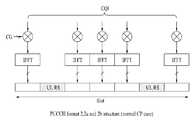
도 11b는 PUCCH 2/2a/2b 구조를 나타낸다. CQI 신호가 전송된다.11B shows a
도 11b를 참조하면, 정상 CP인 경우, 슬롯은 7개의 SC-FDMA 심볼을 포함하고 2번째 및 6번째 SC-FDMA에 기준 신호가 실린다. 남은 SC-FDMA 심볼에는 CQI 신호가 실린다. 확장 CP인 경우 슬롯은 6개의 SC-FDMA 심볼을 포함하고 4번째 SC-FDMA 심볼에 기준 신호가 실린다. CQI는 SC-FDMA 심볼 전체에 변조되어 전달되고 SC-FDMA 심볼은 하나의 시퀀스로 구성된다. 즉, 단말은 각 시퀀스에 CQI를 변조해서 전송한다. CQI는 QPSK 방식으로 변조되고 서브프레임은 최대 20비트의 CQI 값을 실을 수 있다. 기준 신호는 순환 쉬프트에 의해 CDM(Code Division Multiplexing)으로 단말 다중화될 수 있다. 예를 들어, 가용 순환 쉬프트가 12개이면, 12명의 단말이 동일한 RB에 다중화될 수 있고, 가용 순환 쉬프트가 6개이면, 6명의 단말이 다중화될 수 있다.Referring to FIG. 11B, in case of a normal CP, a slot includes seven SC-FDMA symbols and reference signals are carried on the second and sixth SC-FDMA. The remaining SC-FDMA symbols carry a CQI signal. In the case of an extended CP, the slot includes six SC-FDMA symbols and a reference signal is carried on the fourth SC-FDMA symbol. The CQI is modulated and transmitted throughout the SC-FDMA symbol, and the SC-FDMA symbol is composed of one sequence. That is, the terminal modulates and transmits the CQI in each sequence. The CQI is modulated by the QPSK scheme and the subframe may carry a CQI value of up to 20 bits. The reference signal may be terminal multiplexed by code division multiplexing (CDM) by cyclic shift. For example, if there are 12 available cyclic shifts, 12 terminals may be multiplexed in the same RB. If there are 6 available cyclic shifts, 6 terminals may be multiplexed.
이하, PUCCH 자원에 대해 보다 구체적으로 설명한다. PUCCH 자원은 시퀀스의 순환 쉬프트, 직교 코드 및 주파수 자원블록을 포함한다.Hereinafter, the PUCCH resource will be described in more detail. PUCCH resources include cyclic shifts of sequences, orthogonal codes and frequency resource blocks.
수학식 2는 길이 12의 기본 CG-CAZAC 시퀀스를 나타낸다.

여기에서, u 및

표 5 및 6은 각각 PUCCH에 사용되는 길이 4 및 3의 직교 시퀀스를 예시한다.Tables 5 and 6 illustrate orthogonal sequences of


표 7은 기준 신호에 사용되는 직교 시퀀스를 예시한다.Table 7 illustrates an orthogonal sequence used for the reference signal.

수학식 3은 슬롯 ns에서 PUCCH 전송에 사용되는 물리 자원 블록(Physical Resource Block; PRB)을 나타낸다.

여기에서, m은 PUCCH 포맷에 따라 결정된다. PUCCH 포맷 1/1a/1b 및 2/2a/2b에 따른 m은 각각 수학식 4 및 5와 같다.Here, m is determined according to the PUCCH format. M according to the PUCCH formats 1 / 1a / 1b and 2 / 2a / 2b are represented by


도 12는 PUCCH 포맷 1a/1b에 대한 ACK/NACK 채널화(channelization)를 예시한다. 본 예시는 PUCCH 포맷 2/2a/2b에도 유사하게 적용된다.12 illustrates ACK / NACK channelization for
도 12를 참조하면, ACK/NACK 채널화는 CG-CAZAC 시퀀스의 순환 쉬프트(Cyclic Shift; CS)와 직교 커버링(Orthogonal Covering; OC)의 조합에 의해 결정된다. ACK/NACK 채널은 CS 및 OC 자원 상에서 가능한 한 멀리 떨어지도록 조합된다. 인접 ACK/NACK 채널간의 CS 차이(△PUCCHshift)는 셀 별로 정해지며 1, 2 또는 3의 값을 갖는다. 본 실시예는 △PUCCHshift가 2인 경우를 가정한다. 이 경우, ACK/NACK 채널화는 CS 자원을 이용하여 수행된 뒤, OC 자원을 이용하여 수행된다. ACK/NACK 채널에 대한 자원을 (CS,OC)로 표시할 경우, ACK/NACK 채널에 대한 자원은 (1,0), (3,0), (5,0), (7,0), (9,0), (11,0), (2,1), (4,1), (6,1), ..., (7,2), (9,2), (11,2)과 같이 주어진다. 비-영구(Non-persistent) 스케줄링에 대한 ACK/NACK 자원(즉, CS, 왈시/DFT 코드, 주파수 RB)는 스케줄링을 위해 할당된 PDCCH의 가장 낮은 CCE 인덱스에 링크(linking) 되어 자동적으로 결정된다. 영구(Persistent) 스케줄링의 경우에는 단말에게 ACK/NACK 자원에 대한 정보가 한번 명시적(explicit)으로 시그널링 된다.Referring to FIG. 12, ACK / NACK channelization is determined by a combination of Cyclic Shift (CS) and Orthogonal Covering (OC) of a CG-CAZAC sequence. The ACK / NACK channel is combined to be as far apart as possible on the CS and OC resources. The CS difference (ΔPUCCHshift ) between adjacent ACK / NACK channels is determined for each cell and has a value of 1, 2, or 3. This embodiment assumes a case where ΔPUCCHshift is 2. In this case, ACK / NACK channelization is performed using CS resources and then using OC resources. If the resource for the ACK / NACK channel is represented as (CS, OC), the resources for the ACK / NACK channel is (1,0), (3,0), (5,0), (7,0), (9,0), (11,0), (2,1), (4,1), (6,1), ..., (7,2), (9,2), (11,2 Is given by ACK / NACK resources (ie CS, Walsh / DFT code, frequency RB) for non-persistent scheduling are automatically determined by linking to the lowest CCE index of the PDCCH allocated for scheduling. . In the case of persistent scheduling, information on the ACK / NACK resource is explicitly signaled to the UE once.
도 13은 혼합 구조에서 ACK/NACK 및 CQI 채널화를 예시한다.13 illustrates ACK / NACK and CQI channelization in a mixed structure.
도 13을 참조하면, ACK/NACK 및 CQI를 위한 자원은 CS로 구분된다. 일 예로, ACK/NACK 채널화에는 0 내지 3의 CS가 사용되고, CQI 채널화에는 5 내지 10의 CS가 사용될 수 있다. 이 경우, 4 및 11의 CS는 채널 간의 간섭을 피하기 위해 가드 CS로 사용될 수 있다. 도 12 및 13에서, CS는 셀간 간섭을 랜덤화 하기 위해 심볼 단위로 호핑될 수 있다. 또한, 슬롯 단위로 CS/OC가 재-매핑될 수 있다.Referring to FIG. 13, resources for ACK / NACK and CQI are divided into CSs. For example, CS of 0 to 3 may be used for ACK / NACK channelization, and CS of 5 to 10 may be used for CQI channelization. In this case, the
상술한 바와 같이, PUCCH 포맷 1/1a/1b의 자원은 순환 쉬프트(Cyclic Shift; CS), 직교 커버링(Orthogonal Covering; OC) 및 주파수 자원블록(Resource Block; RB)의 조합으로 구성된다. 일 예로, CS의 인덱스가 ncs0~ncs5 (6개), OC의 인덱스가 noc0~noc2 (3개)이고 주파수 RB가 nrb0~nrb2 (3개)이면, 총 54(=6×3×3)개의 자원을 각각의 단말에게 할당할 수 있다. 즉, nr=(ncs, noc, nrb)의 조합으로 인덱스를 0~53까지 다시 정렬할 수 있다. 유사하게, PUCCH 포맷 2/2a/2b의 자원은 순환 쉬프트(Cyclic Shift; CS) 및 주파수 자원블록(Resource Block; RB)의 조합으로 구성된다. 일 예로, CS의 인덱스가 ncs0~ncs5(6개)이고 주파수 RB가 nrb0~nrb2 (3개) 라고 가정하면, 총 18(=6×3)개의 자원을 각각의 단말에게 할당할 수 있다.As described above, the resource of the
다음으로, PUSCH에 사용되는 기준 신호에 대해 보다 구체적으로 설명한다. LTE 시스템에서 기준 신호는 CG-CAZAC 또는 CAZAC 시퀀스로 구성된다. 수학식 6은 PUSCH를 위한 기준 신호를 나타낸다.Next, the reference signal used for the PUSCH will be described in more detail. In the LTE system, the reference signal consists of a CG-CAZAC or CAZAC sequence.

여기에서, m은 0 또는 1이고, n은 0 내지 MRSSC-1의 정수이며, MRSSC는 스케줄링된 부반송파의 개수를 나타낸다. u는 그룹 인덱스를 나타내고 0 내지 29의 정수이다. v는 각각의 그룹에 속하는 기본 시퀀스 번호를 나타낸다. 각각의 그룹은 5 RB 이하의 자원에 대해 하나의 기본 시퀀스 및 6 RB 이상의 자원에 대해 두 개의 기본 시퀀스를 포함한다. α는 순환 쉬프트(CS) 값을 나타내고, 2π·nCS/12로 정의된다. nCS는 수학식 7과 같다.Here, m is 0 or 1, n is an integer of 0 to MRSSC -1, and MRSSC represents the number of scheduled subcarriers. u represents a group index and is an integer from 0 to 29. v represents a base sequence number belonging to each group. Each group contains one base sequence for resources below 5 RB and two base sequences for resources above 6 RB. α represents a cyclic shift (CS) value and is defined as 2 pi nCS / 12. nCS is the same as

여기에서, n(1)DMRS는 방송되는 값이고, n(2)DMRS는 상향링크 스케줄링에 의해 지시되며 표 8과 같다. nPRS(ns)는 셀 특정 순환 쉬프트 값을 나타내고 슬롯 번호(nS)에 따라 달라진다. nPRS(ns)는 수학식 8과 같이 나타낼 수 있다.Here, n(1)DMRS is a broadcast value, n(2)DMRS is indicated by uplink scheduling and is shown in Table 8. nPRS (ns ) represents a cell specific cyclic shift value and depends on the slot number nS. nPRS (ns ) may be expressed as

여기에서, c(i)는 셀 특정 PN(Pseudo-random Noize) 시퀀스이다. PN 시퀀스 생성기는 수학식 9의 값으로 초기화 된다.Here, c (i) is a cell specific pseudo-random noize (PN) sequence. The PN sequence generator is initialized to the value of


PUSCH를 위한 기준 신호의 물리적 매핑은 다음과 같다. 시퀀스 rPUSCH(·)는 진폭 스케일링 인자 βPUSCH와 곱해진 뒤, rPUSCH(0)부터 시작해서 해당 PUSCH 전송에 사용되는 물리 자원블록에 매핑된다.The physical mapping of the reference signal for the PUSCH is as follows. The sequence rPUSCH (·) is multiplied by an amplitude scaling factor βPUSCH and then mapped to a physical resource block used for transmission of the corresponding PUSCH starting from rPUSCH (0).
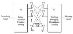
도 14는 다중안테나를 사용하는 무선 통신 시스템의 구성 예를 나타낸다. 다중안테나(Multiple-Input Multiple-Output; MIMO) 기술은 다중 송신 안테나 및/또는 다중 수신 안테나를 사용하여 통신을 수행하는 기술을 말한다.14 shows an example of the configuration of a wireless communication system using multiple antennas. Multiple-Input Multiple-Output (MIMO) technology refers to a technology for performing communication using multiple transmit antennas and / or multiple receive antennas.
다중안테나 기술은 다양한 채널 경로를 통과한 심볼들을 이용하여 전송 신뢰도를 높이는 송신 다이버시티(Transmit diversity; TxD) 방식과, 다수의 송신 안테나를 이용하여 다수의 데이터 심볼을 동시에 전송하여 전송률을 향상시키는 공간 다중화(spatial multiplexing) 방식이 있다. 또한, 두 가지 방식을 적절히 결합하여 각각의 장점을 적절히 얻고자 하는 연구도 최근 많이 연구되고 있다. 각각의 방식에 대해 좀더 구체적으로 살펴보면 다음과 같다.Multi-antenna technology is a transmit diversity (TxD) scheme that improves transmission reliability by using symbols that pass through various channel paths, and a space that improves a transmission rate by simultaneously transmitting a plurality of data symbols using a plurality of transmit antennas. There is a spatial multiplexing scheme. In addition, many studies have been recently conducted to properly combine the two methods to obtain the advantages of each. The following is a more detailed description of each method.
첫째, 송신 다이버시티 방식은 시공간 블록 부호(Space Time Block Coding; STBC) 계열 방식과 다이버시티 이득(Diversity Gain)과 부호화 이득(Coding Gain)을 동시에 이용하는 시공간 트렐리스 부호(Space Time Trellis Code) 계열 방식을 포함한다. 비트 오류율(Bit Error Rate) 개선 성능과, 부호 생성 자유도는 트렐리스 부호 방식이 우수하지만 연산 복잡도(Computation Complexity)는 시공간 블록 부호가 간단하다. 송신 다이버서티 이득은 송신 안테나 수와 수신 안테나 수의 곱에 해당되는 양을 얻을 수 있다. 송신 다이버시티 방식은 순환 지연 다이버시티(Cyclic Delay Diviersity; CDD), PVS(Precoding Vector Switching), TSTD(Time Switched Transmit Diversity), SC-SFBC(Single Carrier-Space Frequence Block Coding), STBC-II, FSTD(Frequency Shift Time Diversity) 등을 포함한다.First, the transmit diversity scheme is a space time block coding (STBC) sequence and a space time trellis code sequence that uses diversity gain and coding gain simultaneously. Include the method. Although the Bit Error Rate improvement performance and the code generation degree of freedom are excellent in the trellis coding scheme, the computational complexity is simple in space-time block codes. The transmit diversity gain can obtain an amount corresponding to the product of the number of transmit antennas and the number of receive antennas. Transmit diversity schemes include Cyclic Delay Diversity (CDD), Precoding Vector Switching (PVS), Time Switched Transmit Diversity (TSTD), Single Carrier-Space Frequence Block Coding (SC-SFBC), STBC-II, FSTD (Frequency Shift Time Diversity) and the like.
둘째, 공간 다중화 기법은 각 송신 안테나를 통해 서로 다른 데이터 열을 송신한다. 이때, 송신기로부터 동시에 전송된 데이터 사이에는 상호 간섭이 발생하므로, 수신기는 적절한 신호처리 기법을 이용하여 상호 간섭을 제거한 뒤에 신호를 검출한다. 간섭 제거 방식의 예는 최대 우도(maximum likelihood; ML) 방식, ZF(Zero Forcing) 방식, MMSE(Minimum Mean Square Error) 방식, D-BLAST(Diagonal Bell Laboratories Layered Space-Time) 방식, V-BLAST(Vertical Bell Labs Layered Space-Time) 방식 등을 포함한다. 송신기가 채널 정보를 알 수 있는 경우에는 SVD(Singular Value Decomposition) 방식 등을 사용할 수 있다.Second, the spatial multiplexing technique transmits different data sequences through each transmit antenna. In this case, since mutual interference occurs between data transmitted simultaneously from the transmitter, the receiver detects a signal after removing the mutual interference using an appropriate signal processing technique. Examples of interference cancellation methods include maximum likelihood (ML), zero forcing (ZF), minimum mean square error (MMSE), diagonal bell laboratories layered space-time (D-BLAST), and V-BLAST ( Vertical Bell Labs Layered Space-Time). When the transmitter can know the channel information, the SVD (Singular Value Decomposition) method may be used.
셋째, 송신 다이버시티와 공간 다중화가 결합된 하이브리드(Hybrid) 방식을 사용할 수 있다. 공간 다이버시티 이득만을 얻을 경우 다이버시티 차수의 증가에 따른 성능개선 이득이 점차 포화되며, 공간 다중화 이득만을 취하면 무선 채널에서 전송 신뢰도가 떨어진다. 이러한 하이브리드 방식은 이중 시공간 전송 다이버시티(Double-Space Time Transmit Diversity; D-STTD), 시공간 BICM(Space Time Bit-Interleaved Coded Modulation; STBICM) 등을 포함한다.Third, a hybrid scheme in which transmission diversity and spatial multiplexing are combined may be used. If only the spatial diversity gain is obtained, the performance improvement gain is gradually saturated as the diversity order is increased, and if only the spatial multiplexing gain is taken, transmission reliability is deteriorated in the wireless channel. Such hybrid schemes include Double-Space Time Transmit Diversity (D-STTD), Space Time Bit-Interleaved Coded Modulation (STBICM), and the like.
수학식 10은 NT개의 송신 안테나가 있는 경우, 각각의 송신 안테나를 통해 전송되는 신호를 나타낸다.

여기에서,


공간 다중화는 서로 다른 신호를 다중화하여 보내므로 정보 벡터

수학식 11은 NR개의 수신 안테나가 있는 경우, 각각의 수신 안테나를 통해 수신되는 신호

여기에서,

한편, 행렬의 랭크(rank)는 서로 독립인 행 또는 열의 개수 중에서 최소 개수로 정의된다. 따라서, 채널 행렬


랭크의 다른 정의는 행렬을 고유치 분해(Eigen value decomposition) 하였을 때, 0이 아닌 고유치들의 개수로 정의할 수 있다. 유사하게, 랭크의 또 다른 정의는 특이치 분해(singular value decomposition) 하였을 때, 0이 아닌 특이치들의 개수로 정의할 수 있다. 따라서, 채널 행렬에서 랭크의 물리적인 의미는 주어진 채널에서 서로 다른 정보를 보낼 수 있는 최대 수라고 할 수 있다.Another definition of rank may be defined as the number of nonzero eigenvalues when the matrix is eigenvalue decomposition. Similarly, another definition of rank may be defined as the number of nonzero singular values when singular value decomposition is performed. Therefore, the physical meaning of rank in the channel matrix is the maximum number that can send different information in a given channel.
다중안테나 시스템에서 송신기와 수신기는 MIMO 기술을 적용하기 위한 코드북(Codebook)을 공유할 수 있다. 코드북은 미리 정의된 프리코딩 행렬 또는 벡터의 집합을 의미한다. 프리코딩 행렬은 NT×NL 크기를 가진다. NT는 신호 전송에 사용하는 안테나의 개수를 나타내고, NL은 레이어의 개수를 나타낸다. 레이어의 개수는 채널 행렬의 랭크에 따라 결정될 수 있다. 프리코딩 행렬은 네스티드(nested) 형태로 구성될 수 있다. 한편, LTE는 2개의 안테나 포트를 사용하는 경우, 코드북을 표 9와 같이 정의하고 있다. 4개의 안테나 포트를 사용하는 경우의 코드북은 3GPP TS36.211을 참조할 수 있다.In a multiple antenna system, a transmitter and a receiver may share a codebook for applying MIMO technology. A codebook means a set of predefined precoding matrices or vectors. The precoding matrix has a size NT × NL. NT represents the number of antennas used for signal transmission, and NL represents the number of layers. The number of layers may be determined according to the rank of the channel matrix. The precoding matrix may be configured in a nested form. Meanwhile, when LTE uses two antenna ports, the codebook is defined as shown in Table 9. For codebooks using four antenna ports, see 3GPP TS36.211.

도 15는 다중안테나를 지원하는 SC-FDMA 송신기의 일 예를 나타낸다.15 shows an example of an SC-FDMA transmitter supporting multiple antennas.
도 15를 참조하면, 스크램블링 모듈(Scrambling, 1210#1-1210#NCW)은 NCW개의 부호어(Codeword;CW)를 단말의 특정 스크램블링 코드/시퀀스를 사용하여 비트 스트림을 스크램블링할 수 있다. NCW개의 스크램블링된 신호는 변조 매퍼(Modulation mapper, 1520#1-1520#NCW)에 입력되어 전송 신호의 종류 및/또는 채널 상태에 따라 BPSK, QPSK 또는 16 QAM 방식으로 복소 심볼로 변조된다. 그 후, NCW개의 변조된 복소 심볼은 레이어 매퍼(Layer mapper, 1530)를 통해 NL개의 레이어로 매핑된다. 각각의 레이어는 변환 프리코더(Transform precoder, 1540#1-1540#NT)에 의해 DFT 변환된다. 프리코더(Precoder, 1545)는 프리코딩 벡터/행렬을 이용하여 DFT 변환된 NL개의 레이어를 안테나 포트에 대응되는 NT개의 스트림으로 매핑한다. 자원 요소 매퍼(Resource element mapper, 1550#1-1550#NT)는 NT개의 스트림을 부반송파에 매핑한다. SC-FDMA 신호 생성기(1560#1-1560#NT)는 부반송파에 매핑된 신호를 시간 영역 상의 전송 심볼로 변환한 뒤 안테나 포트로 전달한다. 안테나 포트는 안테나 가상화(antenna virtualization)을 통해 물리 안테나로 매핑된다.Referring to FIG. 15, the scrambling module 1210 # 1-1210 # NCW may scramble a bit stream using NCW codewords (CWs) using a specific scrambling code / sequence of the UE. The NCW scrambled signals are input to a
도 16은 STBC(Sequence Time Block Coding) 방식을 예시한다. STBC는 CM(Cubic Metric) 특성이 낮도록 단일 반송파 특성을 만족시키면서 주파수-시간 블록 코드를 수행하여 송신 다이버시티 이득을 얻는 방식이다.16 illustrates a sequence time block coding (STBC) scheme. STBC is a method of obtaining a transmit diversity gain by performing a frequency-time block code while satisfying a single carrier characteristic so that a cubic metric (CM) characteristic is low.
도 16을 참조하면, 정보 비트는 QAM 심볼 변조를 통해 길이 2M의 QAM 심볼을 생성한다고 가정한다. 길이 2M의 QAM 심볼은 길이 M-포인트 DFT 코드를 수행하여 STBC 매핑을 수행한다.Referring to FIG. 16, it is assumed that an information bit generates a QAM symbol having a length of 2M through QAM symbol modulation. A QAM symbol of
- 안테나#0, OFDM 심볼#0 => 인덱스 0~M-1의 심볼을 DFT 수행 후 매핑-
- 안테나#1, OFDM 심볼#0 => 인덱스 M~2M-1의 심볼을 DFT 수행 후 매핑-
- 안테나#0, OFDM 심볼#1 => 인덱스 M~2M-1의 심볼을 DFT 수행 후 "-"를 곱하고 복소 공액 수행 후 매핑 (또는 상기 안테나#1, OFDM 심볼#0 매핑 시 사용했던 DFT 결과 값에 "-"를 곱하고 복소 공액 수행)-
- 안테나#1, OFDM 심볼#1 => 인덱스 0~M-1의 심볼을 DFT 수행 후 "-"를 곱하고 복소 공액 수행 후 매핑 (또는 상기 안테나#0, OFDM 심볼#0 매핑 시 사용했던 DFT 결과 값에 "-"를 곱하고 복소 공액 수행)-
STBC(Space Time Block Coding) 방식을 PUCCH 포맷 2/2a/2b에 적용할 경우, STBC 방식은 직교 자원으로 확산 전 또는 확산 후의 변조 심볼에 적용될 수 있다.When the Space Time Block Coding (STBC) scheme is applied to the PUCCH formats 2 / 2a / 2b, the STBC scheme may be applied to modulation symbols before or after spreading as orthogonal resources.
도 17은 순환 지연 다이버시티(Cyclic Delay Diversity; CDD)를 나타낸다.17 shows Cyclic Delay Diversity (CDD).
도 17을 참조하면, CDD는 다중 안테나 전송에 있어서 같은 신호를 전송하되 OFDM 심볼 단위 또는 일정 주기 단위에 해당하는 신호를 안테나 별로 서로 다른 순환 쉬프트(또는 선형 지연)를 적용하여 다이버시티 이득을 얻는 전송 방식이다. 본 실시예에서 안테나#0 및 안테나#1은 동일한 정보를 전송하지만, 안테나#1을 통해 전송되는 심볼은 δ 만큼 순환 쉬프트 된다.Referring to FIG. 17, in the multi-antenna transmission, the CDD transmits the same signal but obtains diversity gain by applying different cyclic shifts (or linear delays) for each antenna corresponding to an OFDM symbol unit or a certain period unit. That's the way. In the present embodiment,
도 18은 OSRT(Orthogonal Space Resource Transmission) 방식을 예시한다. OSRT 방식은 ORT(Orthogonal Resource Transmission) 방식으로도 불린다.18 illustrates an Orthogonal Space Resource Transmission (OSRT) scheme. The OSRT method is also called an orthogonal resource transmission (ORT) method.
도 18을 참조하면, 각 안테나를 통해 전송되는 변조 심볼은 서로 다른 직교 자원을 이용할 수 있다. 직교 자원의 예는 순환 쉬프트, 직교 커버링, 주파수 자원 블록을 포함한다. 즉, 각 안테나를 통해 전송되는 변조 심볼의 자원(순환 쉬프트, 직교 코드, 물리 자원블록)을 서로 직교하게 함으로써 높은 다이버시티 이득을 얻으면서 단말간에 직교성을 보장하는 것이 가능하다. 본 실시예는 변조 심볼(d_0(n))이 주파수 영역 또는 시간 영역에서 각 안테나 별로 서로 다른 시퀀스를 이용하여 확산된 경우를 예시한다. OSRT 방식은 PUCCH 전송에 적용될 수 있다.Referring to FIG. 18, modulation symbols transmitted through each antenna may use different orthogonal resources. Examples of orthogonal resources include cyclic shift, orthogonal covering, and frequency resource blocks. That is, by orthogonalizing the resources (cyclic shift, orthogonal code, physical resource block) of the modulation symbol transmitted through each antenna, it is possible to ensure orthogonality between terminals while obtaining high diversity gain. This embodiment exemplifies a case in which the modulation symbol d_0 (n) is spread using a different sequence for each antenna in a frequency domain or a time domain. The OSRT scheme may be applied to PUCCH transmission.
상술한 바와 같이, LTE-A 시스템은 상향링크에서 다중안테나를 사용할 것을 요구하고 있고, 다양한 MIMO 전송 기법이 고려되고 있다. 이와 관련하여, MIMO 전송 기법(예, TxD 기법)에 대한 단말 동작의 정의가 필요하다. 일 예로, PUCCH의 경우, 2-TxD 기법을 사용하기 위해서는 기준 신호 관점에서 CS, OC 및 PRB의 조합으로 지시되는 2개의 서로 다른 자원이 안테나 각각의 채널을 추정하는 데 필요하다. 다른 예로, PUSCH의 경우, 안테나 각각의 채널 추정을 위해 기준 신호 관점에서 2개의 CS가 할당 되거나, FDM/TDM 형태로 다중화 되는 2개의 자원이 안테나 채널 추정을 위해 할당 되어야 한다.As described above, the LTE-A system requires the use of multiple antennas in the uplink, and various MIMO transmission schemes are considered. In this regard, it is necessary to define a terminal operation for the MIMO transmission scheme (eg, TxD scheme). For example, in the case of PUCCH, two different resources indicated by a combination of CS, OC, and PRB are required for estimating each channel of an antenna in order to use the 2-TxD scheme. As another example, in the case of PUSCH, two CSs may be allocated in terms of reference signals for channel estimation of each antenna, or two resources multiplexed in FDM / TDM form should be allocated for antenna channel estimation.
따라서, 단말 다중화 또는 자원 상황에 따라 단말의 다중안테나 전송 모드(MIMO 전송 모드)를 기지국이 설정하는 것이 필요하다. 예를 들어, 모든 단말이 PUCCH에 대해 1-Tx 안테나 전송을 하는 경우에 18명의 단말이 CDM/FDM 형태로 다중화 될 수 있다고 가정하면, 2-Tx 안테나 전송을 사용하는 경우 단말은 2개의 PUSCH 자원을 사용하게 되므로 다중화 용량이 9명의 단말로 감소한다. 따라서, 기지국이 상황에 따라 단말의 다중안테나 전송 기법을 설정하는 것이 필요하다.Therefore, it is necessary for the base station to set the multiple antenna transmission mode (MIMO transmission mode) of the terminal according to the terminal multiplexing or resource situation. For example, assuming that 18 UEs can be multiplexed in the form of CDM / FDM when all UEs transmit 1-Tx antennas for PUCCH, the UE uses two PUSCH resources when 2-Tx antenna transmission is used. Since the multiplexing capacity is reduced to nine terminals. Therefore, it is necessary for the base station to set the multiple antenna transmission scheme of the terminal according to the situation.
이하, 도면을 참조하여 구체적으로 설명한다. 본 명세서에서 N-Tx 전송 또는 N-Tx 안테나 전송은 N-개의 안테나 각각에 채널 추정이 필요한 전송을 의미한다. 일 예로, 단말이 4개의 물리 안테나를 가지고 있고 2-Tx 안테나 전송을 한다면, 2개의 안테나는 STBC, SFBC, OSRT 등을 이용하고 나머지 2개의 안테나는 CDD, PVS 등과 같은 가상화(virtualization) 방법을 이용할 수 있다. 즉, 단말은 실제로 4개의 안테나를 이용하여 전송하지만, 기지국에서는 단말이 2개의 안테나로 전송한 것과 같이 보이게 된다.Hereinafter, with reference to the drawings will be described in detail. In this specification, N-Tx transmission or N-Tx antenna transmission means transmission in which channel estimation is required for each of the N-antennas. For example, if a terminal has four physical antennas and transmits a 2-Tx antenna, two antennas use STBC, SFBC, OSRT, etc., and the other two antennas use a virtualization method such as CDD, PVS, and the like. Can be. That is, the terminal actually transmits using four antennas, but the base station looks as if the terminal transmits with two antennas.
도 19는 본 발명의 일 실시예에 따라 다중안테나를 통해 상향링크 전송을 수행하는 과정을 예시한다.19 illustrates a process of performing uplink transmission through multiple antennas according to an embodiment of the present invention.
도 19를 참조하면, 기지국은 단말의 다중안테나 전송 모드를 결정한다(S1910). 다중안테나 전송 모드는 채널 조건, 상향링크 전송을 하려는 단말의 개수 등을 고려하여 결정될 수 있다. 그 후, 기지국은 다중안테나 전송 모드에 관한 정보를 단말에게 시그널링 한다(S1920). 다중안테나 전송 모드에 관한 정보는 MIMO 전송 기법 사용 여부, MIMO 전송 기법, 채널 추정이 요구되는 안테나의 개수 등을 포함할 수 있다. 일 예로, 다중안테나 전송 모드에 관한 정보는 송신 다이버시티(TxD) 사용 여부를 포함할 수 있다. 이 경우, 다중안테나 전송 모드에 관한 정보는 1-TxD, 2-TxD, 4-TxD 등의 사용 여부에 대해 지시할 수 있다. 다중안테나 전송 모드에 관한 정보는 시스템 정보, RRC(Radio Resource Control) 시그널링 및 상향링크 스케줄링 정보 중에서 어느 하나를 통해 전송될 수 있다. 다중안테나 전송 모드에 관한 정보는 새롭게 추가된 필드를 통해 전송되거나, 기존에 정의된 필드 중에서 사용되지 않고 있는 필드를 이용하여 전송될 수 있다. 다중안테나 전송 모드에 관한 정보는 주기적, 비-주기적, 정적(persistent), 반-정적(semi-persistent)(broadcast channel) 또는 이벤트-트리거링 방식(UE-RRC signaling)으로 전송될 수 있다. 단말은 기지국이 지시하는 대로 자신의 다중안테나 전송 모드를 설정한다(S1930). 그 후, 단말은 설정된 다중안테나 전송 모드에 따라 상향링크 신호를 다중안테나를 통해 기지국으로 전송한다(S1940). 상향링크 신호는 복수의 SC-FDMA 심볼을 포함하는 상향링크 채널을 통해 전송될 수 있다. 이 경우, 상향링크 채널은 PUCCH 또는 PUSCH를 포함한다.Referring to FIG. 19, the base station determines the multi-antenna transmission mode of the terminal (S1910). The multi-antenna transmission mode may be determined in consideration of channel conditions, the number of UEs to perform uplink transmission, and the like. Thereafter, the base station signals the information on the multi-antenna transmission mode to the terminal (S1920). The information about the multi-antenna transmission mode may include whether the MIMO transmission scheme is used, the MIMO transmission scheme, the number of antennas requiring channel estimation, and the like. As an example, the information about the multi-antenna transmission mode may include whether transmit diversity (TxD) is used. In this case, the information about the multi-antenna transmission mode may indicate whether 1-TxD, 2-TxD, 4-TxD, or the like is used. The information about the multi-antenna transmission mode may be transmitted through any one of system information, RRC (Radio Resource Control) signaling, and uplink scheduling information. Information about a multi-antenna transmission mode may be transmitted through a newly added field or may be transmitted using a field not used among previously defined fields. Information about a multi-antenna transmission mode may be transmitted in a periodic, non-periodic, persistent, semi-persistent (broadcast channel), or event-triggering scheme (UE-RRC signaling). The terminal sets its multi-antenna transmission mode as instructed by the base station (S1930). Thereafter, the terminal transmits an uplink signal to the base station through the multi-antenna according to the configured multi-antenna transmission mode (S1940). The uplink signal may be transmitted through an uplink channel including a plurality of SC-FDMA symbols. In this case, the uplink channel includes a PUCCH or a PUSCH.
도 20은 본 발명의 다른 실시예에 따라 다중안테나를 통해 상향링크 전송을 수행하는 과정을 예시한다.20 illustrates a process of performing uplink transmission through multiple antennas according to another embodiment of the present invention.
도 20을 참조하면, 기지국은 단말의 다중안테나 전송 모드를 결정한다(S2010). 다중안테나 전송 모드는 채널 조건, 상향링크 전송을 하려는 단말의 개수 등을 고려하여 결정될 수 있다. 그 후, 기지국은 다중안테나 전송 모드에 관한 1-비트 정보를 단말에게 시그널링 한다(S2020). 상기 1-비트 정보는 non-TxD 모드 또는 TxD 모드를 지시할 수 있다. 일 예로, 상기 1-비트 정보가 0으로 세팅된 경우 non-TxD 모드를 지시하고 1로 세팅된 경우 2-TxD 모드를 지시할 수 있다. 상기 1-비트 정보는 반대로도 해석될 수 있다. 상기 1-비트 정보는 시스템 정보, RRC(Radio Resource Control) 시그널링 및 상향링크 스케줄링 정보 중에서 어느 하나를 통해 전송될 수 있다. 상기 1-비트 정보는 새롭게 추가된 필드를 통해 전송되거나, 기존에 정의된 필드 중에서 사용되지 않고 있는 필드를 이용하여 전송될 수 있다. 상기 1-비트 정보는 주기적, 비-주기적, 정적(persistent), 반-정적(semi-persistent)(broadcast channel) 또는 이벤트-트리거링 방식(UE-RRC signaling)으로 전송될 수 있다. 단말은 기지국이 지시하는 대로 자신의 다중안테나 전송 모드를 설정한다(S2030). 그 후, 단말은 설정된 다중안테나 전송 모드에 따라 상향링크 신호를 다중안테나를 통해 기지국으로 전송한다(S2040). 상향링크 신호는 복수의 SC-FDMA 심볼을 포함하는 상향링크 채널을 통해 전송될 수 있다. 이 경우, 상향링크 채널은 PUCCH 또는 PUSCH를 포함한다.Referring to FIG. 20, the base station determines a multi-antenna transmission mode of the terminal (S2010). The multi-antenna transmission mode may be determined in consideration of channel conditions, the number of UEs to perform uplink transmission, and the like. Thereafter, the base station signals the 1-bit information about the multi-antenna transmission mode to the terminal (S2020). The 1-bit information may indicate a non-TxD mode or a TxD mode. For example, when the 1-bit information is set to 0, it may indicate a non-TxD mode and when it is set to 1, it may indicate a 2-TxD mode. The 1-bit information can be interpreted vice versa. The 1-bit information may be transmitted through any one of system information, RRC (Radio Resource Control) signaling, and uplink scheduling information. The 1-bit information may be transmitted through a newly added field or by using a field not used among previously defined fields. The 1-bit information may be transmitted in a periodic, non-periodic, persistent, semi-persistent (broadcast channel) or event-triggering scheme (UE-RRC signaling). The terminal sets its multi-antenna transmission mode as instructed by the base station (S2030). Thereafter, the terminal transmits an uplink signal to the base station through the multi-antenna according to the configured multi-antenna transmission mode (S2040). The uplink signal may be transmitted through an uplink channel including a plurality of SC-FDMA symbols. In this case, the uplink channel includes a PUCCH or a PUSCH.
도 21은 본 발명의 또 다른 실시예에 따라 다중안테나를 통해 상향링크 전송을 수행하는 과정을 예시한다.21 illustrates a process of performing uplink transmission through multiple antennas according to another embodiment of the present invention.
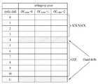
도 21을 참조하면, 기지국은 단말의 다중안테나 전송 모드를 결정한다(S2110). 다중안테나 전송 모드는 채널 조건, 상향링크 전송을 하려는 단말의 개수 등을 고려하여 결정될 수 있다. 그 후, 기지국은 하나 이상의 PUCCH 자원을 단말에게 할당한다(S2120). PUCCH 자원은 포맷에 따라 (CS,OC,PRB) 또는 (CS,PRB)에 의해 지시될 수 있다. 기준 신호에 대한 자원은 (CS,OC,PRB)에 의해 지시될 수 있다. PUCCH 자원의 개수의 최대 값은 단말의 안테나 개수와 동일하거나 작게 설정될 수 있다. 일 예로, 단말의 안테나 개수가 4개인 경우, PUCCH 자원의 개수는 최대 2개 또는 4개로 설정될 수 있다. PUCCH 자원은 시스템 정보, RRC(Radio Resource Control) 시그널링 또는 상향링크 스케줄링 정보를 이용하여 할당될 수 있다. 이 경우, PUCCH 자원은 새롭게 추가된 필드를 통해 전송되거나, 기존에 정의된 필드 중에서 사용되지 않고 있는 필드를 이용하여 할당될 수 있다. 또한, PUCCH 자원은 PDCCH의 구성 정보를 이용하여 할당될 수 있다. 일 예로, ACK/NACK 신호를 전송하는 PUCCH 포맷 1a/1b에 관한 자원은 PDCCH를 구성하는 CCE에 관한 정보(예, 마지막 CCE 인덱스)에 기초하여 확인될 수 있다. PUCCH 자원은 주기적, 비-주기적, 정적(persistent), 반-정적(semi-persistent)(broadcast channel) 또는 이벤트-트리거링 방식(UE-RRC signaling)으로 할당될 수 있다. 그 후, 단말은 기지국으로부터 할당받은 PUCCH 자원의 개수에 기초하여 다중안테나 전송 모드를 설정한다(S2130). 일 예로, 기지국이 1개의 자원을 할당한 경우, 단말은 다중안테나 전송 모드를 1-TxD 또는 그의 등가 방법(CDD, PVS 등)으로 설정할 수 있다. 유사하게, 기지국이 2개의 자원을 할당한 경우, 단말은 다중안테나 전송 모드를 2-TxD(예, STBC, SFBC, 대 지연(large delay) CDD, OSRT 등)로 설정할 수 있다. 유사하게, 기지국이 4개의 자원을 할당한 경우, 단말은 다중안테나 전송 모드를 4-TxD로 설정할 수 있다. 그 후, 단말은 설정된 다중안테나 전송 모드에 따라 상향링크 신호를 다중안테나를 통해 기지국으로 전송한다(S2140). 상향링크 신호는 복수의 SC-FDMA 심볼을 포함하는 상향링크 채널을 통해 전송될 수 있다. 이 경우, 상향링크 채널은 PUCCH 또는 PUSCH를 포함한다.Referring to FIG. 21, the base station determines the multi-antenna transmission mode of the terminal (S2110). The multi-antenna transmission mode may be determined in consideration of channel conditions, the number of UEs to perform uplink transmission, and the like. Thereafter, the base station allocates one or more PUCCH resources to the terminal (S2120). PUCCH resources may be indicated by (CS, OC, PRB) or (CS, PRB) depending on the format. The resource for the reference signal may be indicated by (CS, OC, PRB). The maximum value of the number of PUCCH resources may be set equal to or smaller than the number of antennas of the UE. For example, when the number of antennas of the UE is four, the number of PUCCH resources may be set to two or four at maximum. PUCCH resources may be allocated using system information, RRC (Radio Resource Control) signaling or uplink scheduling information. In this case, the PUCCH resource may be transmitted through a newly added field or allocated using a field not used among previously defined fields. In addition, PUCCH resources may be allocated using configuration information of the PDCCH. For example, the resource for the
도 22는 본 발명의 또 다른 실시예에 따라 다중안테나를 통해 상향링크 전송을 수행하는 과정을 예시한다.22 exemplifies a process of performing uplink transmission through multiple antennas according to another embodiment of the present invention.
도 22를 참조하면, 기지국은 단말의 다중안테나 전송 모드를 결정한다(S2210). 다중안테나 전송 모드는 채널 조건, 상향링크 전송을 하려는 단말의 개수 등을 고려하여 결정될 수 있다. 그 후, 기지국은 복수의 PUCCH 자원을 단말에게 할당한다(S2220). PUCCH 자원은 포맷에 따라 (CS,OC,PRB) 또는 (CS,PRB)에 의해 지시될 수 있다. 기준 신호에 대한 자원은 (CS,OC,PRB)에 의해 지시될 수 있다. PUCCH 자원의 개수는 단말의 안테나 개수와 동일하거나 작은 특정 값으로 고정될 수 있다. 일 예로, 단말의 안테나 개수가 4개인 경우, PUCCH 자원의 개수는 항상 2개 또는 4개로 고정될 수 있다. PUCCH 자원은 시스템 정보, RRC(Radio Resource Control) 시그널링 또는 상향링크 스케줄링 정보를 이용하여 할당될 수 있다. 이 경우, PUCCH 자원은 새롭게 추가된 필드를 통해 전송되거나, 기존에 정의된 필드 중에서 사용되지 않고 있는 필드를 이용하여 할당될 수 있다. 또한, PUCCH 자원은 PDCCH의 구성 정보를 이용하여 할당될 수 있다. 일 예로, ACK/NACK 신호를 전송하는 PUCCH 포맷 1a/1b에 관한 자원은 PDCCH를 구성하는 CCE(예, 마지막 CCE)에 관한 정보에 기초하여 확인될 수 있다. PUCCH 자원은 주기적, 비-주기적, 정적(persistent), 반-정적(semi-persistent)(broadcast channel) 또는 이벤트-트리거링 방식(UE-RRC signaling)으로 할당될 수 있다.Referring to FIG. 22, the base station determines the multi-antenna transmission mode of the terminal (S2210). The multi-antenna transmission mode may be determined in consideration of channel conditions, the number of UEs to perform uplink transmission, and the like. Thereafter, the base station allocates a plurality of PUCCH resources to the terminal (S2220). PUCCH resources may be indicated by (CS, OC, PRB) or (CS, PRB) depending on the format. The resource for the reference signal may be indicated by (CS, OC, PRB). The number of PUCCH resources may be fixed to a specific value equal to or smaller than the number of antennas of the UE. As an example, when the number of antennas of the UE is four, the number of PUCCH resources may be fixed at two or four at all times. PUCCH resources may be allocated using system information, RRC (Radio Resource Control) signaling or uplink scheduling information. In this case, the PUCCH resource may be transmitted through a newly added field or allocated using a field not used among previously defined fields. In addition, PUCCH resources may be allocated using configuration information of the PDCCH. For example, a resource for
그 후, 단말은 기지국으로부터 할당받은 PUCCH 자원간의 관계에 기초하여 다중안테나 전송 모드를 설정한다(S2230). 일 예로, 단말은 할당받은 PUCCH 자원들의 동일성 여부에 기초하여 다중안테나 전송 모드를 설정할 수 있다. 하나의 방식으로, 2-Tx 안테나 전송을 위해 각 안테나에 사용될 자원을 지시하는 2개의 필드를 정의할 수 있다. 이 경우, 2개의 필드가 다른 값을 가지고 있으면 2-Tx 안테나 전송(예, STBC, SFBC, 대 지연(large delay) CDD, OSRT)을 하고, 같은 값을 가지고 있으면 1-Tx 안테나 전송 또는 그에 상응하는 전송을 수행할 수 있다. 다른 방식으로, 기지국이 단말에게 nr0과 nr1을 할당해줬다고 가정하자. 여기에서, nr0은 PUCCH 포맷 1/1a/1b에 대해 (ncs0,noc0,n_PRB0)이고, PUCCH 포맷 2/2a/2b에 대해 (ncs0,n_PRB0)로 표현된다. 여기에서, ncs는 순환 쉬프트 값을 나타내고, noc는 직교 커버링 값을 나타내며, n_PRB는 물리 자원블록에 대한 값을 나타낸다. 이 경우, 단말은 nr0=nr1이면 해당 자원을 이용하여 1-Tx 안테나 전송을 수행하고, nr0≠nr1 이면 해당 자원들을 이용하여 2-Tx 안테나 전송을 수행하도록 다중안테나 전송 모드를 설정할 수 있다. 여기서, 할당되는 순서는 각각의 안테나에 상응할 수 있다. 즉, (nr0,nr1)을 시그널링 해 주면 nr0은 안테나0, nr1은 안테나1을 위해 할당된 것으로 할 수 있다. 즉, (nr0,nr1,nr2,nr3) <-> (ant0,ant1,ant2,ant3)의 관계에 있을 수 있다. 여기에서, ant는 안테나 포트를 의미할 수 있다. 즉 각각의 안테나를 위해 할당된 자원(nr)이 서로 같은 값이면 묶어서 하나의 안테나로 가정할 수 있는 Tx 전송 방법으로 전송하고 다른 값이면 미리 정의되는 N-TxD 방식을 적용한다. 이하에서는 (nr0,nr1,nr2,nr3)이 할당된 경우에 대해 보다 구체적으로 설명한다. 편의상, 각 안테나에 대해 자원이 할당된 경우를 가정하지만, 본 발명이 예시한 안테나 순서로 국한되는 것은 아니다.Thereafter, the terminal sets the multi-antenna transmission mode based on the relationship between the PUCCH resources allocated from the base station (S2230). For example, the UE may set a multi-antenna transmission mode based on whether the allocated PUCCH resources are identical. In one way, two fields indicating resources to be used for each antenna for 2-Tx antenna transmission may be defined. In this case, if the two fields have different values, 2-Tx antenna transmission (eg STBC, SFBC, large delay CDD, OSRT), and if they have the same value, 1-Tx antenna transmission or equivalent Can be performed. Alternatively, assume that the base station has allocated nr0 and nr1 to the terminal. Here, nr0 is (ncs0, noc0, n_PRB0) for
- nr0≠nr1≠nr2≠nr3인 경우 4-Tx 안테나 전송할 수 있다.In case of nr0 ≠ nr1 ≠ nr2 ≠ nr3, 4-Tx antenna can be transmitted.
- nr0=nr1≠nr2≠nr3인 경우, ant1, ant2, ant3으로만 전송하거나, ant0는 3-Tx 안테나로 전송하는 것처럼 보이게 전송할 수 있다.If nr0 = nr1 ≠ nr2 ≠ nr3, only ant1, ant2, and ant3 may be transmitted, or ant0 may be transmitted to appear to transmit to a 3-Tx antenna.
- nr0=nr1≠nr2=nr3인 경우, ant0와 ant2만 전송, ant0와 ant3만 전송, ant1과 ant2만 전송, ant1과 ant2만 전송할 수 있다. 또한, ant0와 ant1이 하나로 보이게끔 전송하고 ant2와 ant3이 하나로 보이게끔 전송함으로써 전체적으로는 2-Tx로 보이게 전송할 수 있다.-When nr0 = nr1 ≠ nr2 = nr3, only ant0 and ant2 can be transmitted, only ant0 and ant3 can be transmitted, only ant1 and ant2 can be transmitted, and only ant1 and ant2 can be transmitted. In addition, by transmitting ant0 and ant1 to be seen as one, and ant2 and ant3 to be seen as one, the overall transmission can be seen as 2-Tx.
도 23은 본 발명의 또 다른 실시예에 따라 다중안테나를 통해 상향링크 전송을 수행하는 과정을 예시한다.FIG. 23 illustrates a process of performing uplink transmission through multiple antennas according to another embodiment of the present invention. FIG.
도 23을 참조하면, 기지국은 단말의 다중안테나 전송 모드를 결정한다(S2310). 다중안테나 전송 모드는 채널 조건, 상향링크 전송을 하려는 단말의 개수 등을 고려하여 결정될 수 있다. 그 후, 기지국은 채널 추정이 필요한 Tx 안테나의 개수를 시그널링 한다(S2320). 채널 추정이 필요한 Tx 안테나의 개수는 시스템 정보, RRC(Radio Resource Control) 시그널링 또는 상향링크 스케줄링 정보를 이용하여 할당될 수 있다. 이 경우, 채널 추정이 필요한 Tx 안테나의 개수는 새롭게 추가된 필드를 통해 전송되거나, 기존에 정의된 필드 중에서 사용되지 않고 있는 필드를 이용하여 할당될 수 있다. 채널 추정이 필요한 Tx 안테나의 개수는 주기적, 비-주기적, 정적(persistent), 반-정적(semi-persistent)(broadcast channel) 또는 이벤트-트리거링 방식(UE-RRC signaling)으로 할당될 수 있다.Referring to FIG. 23, the base station determines the multi-antenna transmission mode of the terminal (S2310). The multi-antenna transmission mode may be determined in consideration of channel conditions, the number of UEs to perform uplink transmission, and the like. Thereafter, the base station signals the number of Tx antennas requiring channel estimation (S2320). The number of Tx antennas for which channel estimation is required may be allocated using system information, RRC (Radio Resource Control) signaling, or uplink scheduling information. In this case, the number of Tx antennas requiring channel estimation may be transmitted through a newly added field or may be allocated using a field not used among previously defined fields. The number of Tx antennas for which channel estimation is required may be allocated in a periodic, non-periodic, persistent, semi-persistent (broadcast channel), or event-triggering scheme (UE-RRC signaling).
채널 추정이 필요한 Tx 안테나의 개수는 기준 신호에 대한 CDM/FDM/TDM의 자원 개수를 통해 지시될 수 있다. 기준 신호 자원은 CS, OC, PRB 또는 이들의 임의의 조합에 의해 지시될 수 있다. 일 예로, 기준 신호 자원은 CS를 이용하여 지시될 수 있다. 이 경우, 단말은 다중안테나 전송 모드를 할당받은 자원의 개수에 따라 설정할 수 있다(S2330). 일 예로, 단말은 다중안테나 전송 모드는 할당받은 자원이 1개면 1-Tx 전송, 2개면 2-Tx 전송, 4개면 4-Tx 전송으로 설정할 수 있다. 그 후, 단말은 설정된 다중안테나 전송 모드를 이용하여 상향링크 신호를 다중안테나를 통해 기지국으로 전송한다(S2140). 이 경우, 단말은 할당받은 자원을 이용하여 복수의 안테나에 대한 기준 신호를 기지국으로 전송한다.The number of Tx antennas for which channel estimation is required may be indicated through the number of resources of CDM / FDM / TDM for the reference signal. The reference signal resource may be indicated by CS, OC, PRB or any combination thereof. As an example, the reference signal resource may be indicated using CS. In this case, the terminal may set the multi-antenna transmission mode according to the number of resources allocated (S2330). For example, the UE may set the multi-antenna transmission mode to 1-Tx transmission if one resource is allocated, 2-Tx transmission if two, and 4-Tx transmission if four. Thereafter, the terminal transmits an uplink signal to the base station through the multi-antenna using the configured multi-antenna transmission mode (S2140). In this case, the terminal transmits reference signals for a plurality of antennas to the base station by using the allocated resources.
다른 방식으로, 단계 S2230에서, 채널 추정이 필요한 Tx 안테나의 개수는 N-Tx 전송에 대해 N만을 시그널링 해 줄 수 있다. 이 경우, 단말은 다중안테나 전송 모드를 N-Tx 전송으로 설정한다. 그 후, 단말은 설정된 다중안테나 전송 모드를 이용하여 상향링크 신호를 다중안테나를 통해 기지국으로 전송한다(S2140). 이 경우, 단말은 첫 번째 안테나를 위한 기준 신호 자원으로 기존 시스템(LTE)에 정의된 기준 신호 자원을 사용하고, 나머지 안테나에 대해서는 미리-결정된 기준 신호 자원을 사용할 수 있다. 일 예로, 첫 번째 안테나가 ncs0를 사용하면, 두 번째 안테나는 ncs0+α, 세 번째 안테나는 ncs0+2×α, 네 번째 안테나는 ncs0+3×α를 사용하여 기준 신호를 전송할 수 있다. 여기에서, ncs는 순환 쉬프트 값을 나타낸다. 상향링크 신호는 복수의 SC-FDMA 심볼을 포함하는 상향링크 채널을 통해 전송될 수 있다. 이 경우, 상향링크 채널은 PUCCH 또는 PUSCH를 포함한다.Alternatively, in step S2230, the number of Tx antennas requiring channel estimation may signal only N for N-Tx transmission. In this case, the terminal sets the multi-antenna transmission mode to N-Tx transmission. Thereafter, the terminal transmits an uplink signal to the base station through the multi-antenna using the configured multi-antenna transmission mode (S2140). In this case, the terminal may use a reference signal resource defined in the legacy system (LTE) as a reference signal resource for the first antenna, and use a predetermined reference signal resource for the remaining antennas. For example, when the first antenna uses ncs0, the second antenna may transmit a reference signal using ncs0 + α, the third antenna ncs0 + 2 × α, and the fourth antenna ncs0 + 3 × α. Here, ncs represents a cyclic shift value. The uplink signal may be transmitted through an uplink channel including a plurality of SC-FDMA symbols. In this case, the uplink channel includes a PUCCH or a PUSCH.
도 24는 본 발명의 또 다른 실시예에 따라 다중안테나를 통해 상향링크 전송을 수행하는 과정을 예시한다.24 illustrates a process of performing uplink transmission through multiple antennas according to another embodiment of the present invention.
도 24를 참조하면, 기지국은 단말의 다중안테나 전송 모드를 결정한다(S2410). 다중안테나 전송 모드는 채널 조건, 상향링크 전송을 하려는 단말의 개수 등을 고려하여 결정될 수 있다. 그 후, 기지국은 PUSCH 채널을 위한 기준 신호(Reference Signal; RS)에 대해 복수의 자원을 단말에게 할당한다(S2220). 기준 신호 자원은 CS, OC, PRB 또는 이들의 임의의 조합에 의해 지시될 수 있다. 일 예로, 기준 신호 자원은 CS를 이용하여 지시될 수 있다. 기준 신호 자원의 개수는 단말의 안테나 개수와 동일하거나 작은 특정 값으로 고정될 수 있다. 일 예로, 단말의 안테나 개수가 4개인 경우, 기준 신호 자원의 개수는 항상 2개 또는 4개로 고정될 수 있다. 기준 신호 자원은 상향링크 스케줄링 정보를 이용하여 할당될 수 있다. 표 10은 복수의 기준 신호 자원을 지시하도록 변형된 상향링크 스케줄링 정보(DCI 포맷 0)를 나타낸다.Referring to FIG. 24, the base station determines the multi-antenna transmission mode of the terminal (S2410). The multi-antenna transmission mode may be determined in consideration of channel conditions, the number of UEs to perform uplink transmission, and the like. Thereafter, the base station allocates a plurality of resources to the terminal for a reference signal (RS) for the PUSCH channel (S2220). The reference signal resource may be indicated by CS, OC, PRB or any combination thereof. As an example, the reference signal resource may be indicated using CS. The number of reference signal resources may be fixed to a specific value equal to or smaller than the number of antennas of the terminal. For example, when the number of antennas of the terminal is four, the number of reference signal resources may be fixed at two or four at all times. Reference signal resources may be allocated using uplink scheduling information. Table 10 shows uplink scheduling information (DCI format 0) modified to indicate a plurality of reference signal resources.
그 후, 단말은 기지국으로부터 할당받은 기준 신호 자원간의 관계에 기초하여 다중안테나 전송 모드를 설정한다(S2430). 일 예로, 단말은 할당받은 기준 신호 자원들의 동일성 여부에 기초하여 다중안테나 전송 모드를 설정할 수 있다. 하나의 방식으로, 2-Tx 안테나 전송을 위해 각 안테나에 사용될 자원을 지시하는 2개의 필드를 정의할 수 있다. 이 경우, 2개의 필드가 다른 값을 가지고 있으면 2-Tx 안테나 전송 (예, STBC, SFBC, 대 지연(large delay) CDD, OSRT)을 하고, 같은 값을 가지고 있으면 1-Tx 안테나 전송 또는 그에 상응하는 전송을 수행할 수 있다. 구체적으로, 기지국이 단말에게 ncs0과 ncs1을 할당해줬다고 가정하자. 여기에서, ncs는 순환 쉬프트 값을 나타낸다. 이 경우, 단말은 ncs0=ncs1이면 해당 자원을 이용하여 1-Tx 안테나 전송을 수행하고, ncs0≠ncs1이면 해당 자원들을 이용하여 2-Tx 안테나 전송을 수행하도록 다중안테나 전송 모드를 설정할 수 있다. 여기서, 할당되는 순서는 각각의 안테나에 상응할 수 있다. 즉, (ncs0,ncs1)을 시그널링 해 주면 ncs0은 안테나0, ncs1은 안테나1을 위해 할당된 것으로 할 수 있다. 즉, (ncs0,ncs1,ncs2,ncs3) <-> (ant0,ant1,ant2,ant3)의 관계에 있을 수 있다. 여기에서, ant는 안테나 포트를 의미할 수 있다. 즉 각각의 안테나를 위해 할당된 자원(ncs)이 서로 같은 값이면 묶어서 하나의 안테나로 가정할 수 있는 Tx 전송 방법으로 전송하고 다른 값이면 미리 정의되는 N-TxD 방식을 적용한다. 이하에서는 (ncs0,ncs1,ncs2,ncs3)이 할당된 경우에 대해 보다 구체적으로 설명한다. 편의상, 각각의 안테나에 대해 자원이 할당된 경우를 가정하지만, 본 발명이 이러한 안테나 순서에 국한되는 것은 아니다.Thereafter, the terminal sets the multi-antenna transmission mode based on the relationship between reference signal resources allocated from the base station (S2430). For example, the terminal may set the multi-antenna transmission mode based on whether the assigned reference signal resources are identical. In one way, two fields indicating resources to be used for each antenna for 2-Tx antenna transmission may be defined. In this case, two Tx antenna transmissions (eg STBC, SFBC, large delay CDD, OSRT) if the two fields have different values, and 1-Tx antenna transmission or equivalent Can be performed. Specifically, assume that the base station has allocated ncs0 and ncs1 to the terminal. Here, ncs represents a cyclic shift value. In this case, the terminal may set the multi-antenna transmission mode to perform 1-Tx antenna transmission using the corresponding resource if ncs0 = ncs1, and perform 2-Tx antenna transmission using the corresponding resources if ncs0 ≠ ncs1. In this case, the order of allocation may correspond to each antenna. That is, if (ncs0, ncs1) is signaled, ncs0 may be allocated to
- ncs0≠ncs1≠ncs2≠ncs3인 경우 4-Tx 안테나 전송할 수 있다.If ncs0 ≠ ncs1 ≠ ncs2 ≠ ncs3, 4-Tx antennas can be transmitted.
- ncs0=ncs1≠ncs2≠ncs3인 경우, ant1, ant2, ant3으로만 전송하거나, ant0는 3-Tx 안테나로 전송하는 것처럼 보이게 전송할 수 있다.If ncs0 = ncs1 ≠ ncs2 ≠ ncs3, only ant1, ant2, and ant3 may be transmitted, or ant0 may be transmitted to appear to transmit to a 3-Tx antenna.
- ncs0=ncs1≠ncs2=ncs3인 경우, ant0와 ant2만 전송, ant0와 ant3만 전송, ant1과 ant2만 전송, ant1과 ant2만 전송할 수 있다. 또한, ant0와 ant1이 하나로 보이게끔 전송하고 ant2와 ant3이 하나로 보이게끔 전송함으로써 전체적으로는 2-Tx로 보이게 전송할 수 있다.-When ncs0 = ncs1 ≠ ncs2 = ncs3, only ant0 and ant2 can be transmitted, only ant0 and ant3 can be transmitted, only ant1 and ant2 can be transmitted, and only ant1 and ant2 can be transmitted. In addition, by transmitting ant0 and ant1 to be seen as one, and ant2 and ant3 to be seen as one, the overall transmission can be seen as 2-Tx.
도 25는 본 발명의 일 실시예에 따른 송수신기의 블록도를 예시한다. 하향링크에서, 송신기(2510)는 기지국의 일부이고 수신기(2550)는 단말의 일부이다. 상향링크에서, 송신기(2510)는 단말의 일부이고 수신기(2550)는 기지국의 일부이다.25 illustrates a block diagram of a transceiver in accordance with an embodiment of the present invention. In downlink,
도 25를 참조하면, 송신기(2510)에서 송신(TX) 데이터 및 파일럿 프로세서(2520)는 데이터(예, 트래픽 데이터 및 시그널링)를 인코딩, 인터리빙 및 심볼 맵핑하여 데이터 심볼들을 생성한다. 또한, 프로세서(2520)는 파일럿 심볼들을 생성하여 데이터 심볼들 및 파일럿 심볼들을 다중화한다. 변조기(2530)는 무선 접속 방법에 따라 적합한 전송 심볼을 생성한다. 무선 주파수(Radio Frequency; RF) 모듈(2532)은 상기 전송 심볼을 처리(예, 아날로그 변환, 증폭, 필터링 및 주파수 상향 변환)하여 안테나(2534)를 통해 전송되는 RF 신호를 생성한다. 수신기(2550)에서 안테나(2552)는 송신기(2510)로부터 전송된 신호를 수신하여 RF 모듈(2554)에 제공한다. RF 모듈(2554)는 수신된 신호를 처리(예, 필터링, 증폭, 주파수 하향 변환, 디지털화)하여 입력 샘플들을 제공한다. 복조기(2560)는 입력 샘플들을 복조하여 데이터 값 및 파일럿 값을 제공한다. 채널 추정기(2580)는 수신된 파일럿 값들에 기초하여 채널 추정치를 유도한다. 복조기(2560)는 채널 추정치를 사용하여 수신된 데이터 값들에 데이터 검출(또는 등화)를 수행하고, 송신기(2510)를 위한 데이터 심볼 추정치를 제공한다. Rx 데이터 프로세서(2570)는 데이터 심볼 추정치들을 심볼 디맵핑, 디인터리밍 및 디코딩하고, 디코딩된 데이터를 제공한다. 일반적으로, 수신기(2550)에서 복조기(2560) 및 Rx 데이터 프로세서(2570)에 의한 처리는 송신기(2510)에서 각각 변조기(2530) 및 Tx 데이터 및 파일럿 프로세서(2520)에 의한 처리와 상호 보완된다.Referring to FIG. 25, a transmit (TX) data and a
제어기들/프로세서들(2540 및 2590)은 각각 송신기(2510) 및 수신기(2550)에서 다양한 처리 모듈들의 동작을 감독한다. 구체적으로, 제어기들/프로세서들(2540 및 2590)은 도면을 참조하여 설명한 본 발명의 실시예와 관련된 동작을 수행하기 위하여 디지털 신호 처리 과정을 수행하고 다양한 처리 모듈들의 동작을 감독한다. 메모리(2542 및 2592)는 각각 송신기(2510) 및 수신기(2550)를 위한 프로그램 코드들 및 데이터를 저장한다.Controllers /
이상에서 설명된 실시예들은 본 발명의 구성요소들과 특징들이 소정 형태로 결합된 것들이다. 각 구성요소 또는 특징은 별도의 명시적 언급이 없는 한 선택적인 것으로 고려되어야 한다. 각 구성요소 또는 특징은 다른 구성요소나 특징과 결합되지 않은 형태로 실시될 수 있다. 또한, 일부 구성요소들 및/또는 특징들을 결합하여 본 발명의 실시예를 구성하는 것도 가능하다. 본 발명의 실시예들에서 설명되는 동작들의 순서는 변경될 수 있다. 어느 실시예의 일부 구성이나 특징은 다른 실시예에 포함될 수 있고, 또는 다른 실시예의 대응하는 구성 또는 특징과 교체될 수 있다. 특허청구범위에서 명시적인 인용 관계가 있지 않은 청구항들을 결합하여 실시예를 구성하거나 출원 후의 보정에 의해 새로운 청구항으로 포함시킬 수 있음은 자명하다.The embodiments described above are the components and features of the present invention are combined in a predetermined form. Each component or feature is to be considered optional unless stated otherwise. Each component or feature may be implemented in a form that is not combined with other components or features. It is also possible to combine some of the components and / or features to form an embodiment of the invention. The order of the operations described in the embodiments of the present invention may be changed. Some configurations or features of certain embodiments may be included in other embodiments, or may be replaced with corresponding configurations or features of other embodiments. It is obvious that the claims may be combined to form an embodiment by combining claims that do not have an explicit citation relationship in the claims or as new claims by post-application correction.
본 발명에 따른 실시예는 다양한 수단, 예를 들어, 하드웨어, 펌웨어(firmware), 소프트웨어 또는 그것들의 결합 등에 의해 구현될 수 있다. 하드웨어에 의한 구현의 경우, 본 발명의 일 실시예는 하나 또는 그 이상의 ASICs(application specific integrated circuits), DSPs(digital signal processors), DSPDs(digital signal processing devices), PLDs(programmable logic devices), FPGAs(field programmable gate arrays), 프로세서, 콘트롤러, 마이크로 콘트롤러, 마이크로 프로세서 등에 의해 구현될 수 있다.Embodiments according to the present invention may be implemented by various means, for example, hardware, firmware, software, or a combination thereof. In the case of a hardware implementation, an embodiment of the present invention may include one or more application specific integrated circuits (ASICs), digital signal processors (DSPs), digital signal processing devices (DSPDs), programmable logic devices (PLDs), FPGAs ( field programmable gate arrays), processors, controllers, microcontrollers, microprocessors, and the like.
펌웨어나 소프트웨어에 의한 구현의 경우, 본 발명의 일 실시예는 이상에서 설명된 기능 또는 동작들을 수행하는 모듈, 절차, 함수 등의 형태로 구현될 수 있다. 소프트웨어 코드는 메모리 유닛에 저장되어 프로세서에 의해 구동될 수 있다. 상기 메모리 유닛은 상기 프로세서 내부 또는 외부에 위치하여, 이미 공지된 다양한 수단에 의해 상기 프로세서와 데이터를 주고 받을 수 있다.In the case of implementation by firmware or software, an embodiment of the present invention may be implemented in the form of a module, procedure, function, etc. that performs the functions or operations described above. The software code may be stored in a memory unit and driven by a processor. The memory unit may be located inside or outside the processor, and may exchange data with the processor by various known means.
본 발명은 본 발명의 특징을 벗어나지 않는 범위에서 다른 특정한 형태로 구체화될 수 있음은 당업자에게 자명하다. 따라서, 상기의 상세한 설명은 모든 면에서 제한적으로 해석되어서는 아니되고 예시적인 것으로 고려되어야 한다. 본 발명의 범위는 첨부된 청구항의 합리적 해석에 의해 결정되어야 하고, 본 발명의 등가적 범위 내에서의 모든 변경은 본 발명의 범위에 포함된다.It will be apparent to those skilled in the art that the present invention may be embodied in other specific forms without departing from the spirit of the invention. Accordingly, the above detailed description should not be construed as limiting in all aspects and should be considered as illustrative. The scope of the invention should be determined by reasonable interpretation of the appended claims, and all changes within the equivalent scope of the invention are included in the scope of the invention.
본 발명은 무선 통신 시스템에 적용될 수 있다. 본 발명은 SC-FDMA(Single Carrier-Frequency Division Multiple Access), MC-FDMA(Multi Carrier-Frequency Division Multiple Access) 및 OFDMA(Orthogonal Frequency Division Multiple Access) 중에서 적어도 하나를 지원하는 무선 통신 시스템에 적용될 수 있다. 구체적으로, 본 발명은 무선 통신 시스템에서 단말이 신호를 다중안테나를 통해 상향링 크로 전송하는 방법 및 이를 위한 장치에 적용될 수 있다.The present invention can be applied to a wireless communication system. The present invention can be applied to a wireless communication system supporting at least one of Single Carrier-Frequency Division Multiple Access (SC-FDMA), Multi Carrier-Frequency Division Multiple Access (MC-FDMA), and Orthogonal Frequency Division Multiple Access (OFDMA). . Specifically, the present invention can be applied to a method for transmitting a signal to an uplink through a multi-antenna and a device therefor in a wireless communication system.
본 발명에 관한 이해를 돕기 위해 상세한 설명의 일부로 포함되는, 첨부 도면은 본 발명에 대한 실시예를 제공하고, 상세한 설명과 함께 본 발명의 기술적 사상을 설명한다.BRIEF DESCRIPTION OF THE DRAWINGS The accompanying drawings, which are included as part of the detailed description in order to provide a thorough understanding of the present invention, provide an embodiment of the present invention and together with the description, illustrate the technical idea of the present invention.
도 1은 E-UMTS의 네트워크(Network) 구조를 나타낸다.1 shows a network structure of an E-UMTS.
도 2는 OFDMA 및 SC-FDMA를 위한 송신기 및 수신기의 블록도를 예시한다.2 illustrates a block diagram of a transmitter and a receiver for OFDMA and SC-FDMA.
도 3은 LTE 시스템에 정의된 상향링크 송신기의 구조를 나타낸다.3 shows a structure of an uplink transmitter defined in an LTE system.
도 4는 SC-FDMA 송신기에서 기준 신호(Reference Signal; RS)를 생성하는 방법을 예시하는 블록도이다.4 is a block diagram illustrating a method of generating a reference signal (RS) in an SC-FDMA transmitter.
도 5는 무선 프레임(radio frame)의 구조를 예시한다.5 illustrates a structure of a radio frame.
도 6은 하향링크 물리 채널의 구조를 나타낸다.6 shows a structure of a downlink physical channel.
도 7은 슬롯에 대한 자원 그리드(resource grid)를 예시한다.7 illustrates a resource grid for a slot.
도 8은 로칼화된 SC-FDMA 방식의 자원 매핑을 설명하는 일 예를 나타낸다.8 shows an example for explaining resource mapping in a localized SC-FDMA scheme.
도 9는 클러스터된 SC-FDMA 방식의 자원 매핑을 설명하는 일 예를 나타낸다.9 shows an example for explaining resource mapping in a clustered SC-FDMA scheme.
도 10은 상향링크 서브프레임의 구조를 나타낸다.10 shows a structure of an uplink subframe.
도 11은 PUCCH 구조를 나타낸다.11 shows a PUCCH structure.
도 12는 PUCCH 포맷 1a/1b에 대한 ACK/NACK 채널화(channelization)를 예시한다.12 illustrates ACK / NACK channelization for
도 13은 혼합 구조에서 ACK/NACK 및 CQI 채널화를 예시한다.13 illustrates ACK / NACK and CQI channelization in a mixed structure.
도 14는 다중안테나를 사용하는 무선 통신 시스템의 구성 예를 나타낸다.14 shows an example of the configuration of a wireless communication system using multiple antennas.
도 15는 다중안테나를 지원하는 SC-FDMA 송신기의 일 예를 나타낸다.15 shows an example of an SC-FDMA transmitter supporting multiple antennas.
도 16은 STBC(Sequence Time Block Coding) 방식을 예시한다.16 illustrates a sequence time block coding (STBC) scheme.
도 17은 순환 지연 다이버시티(Cyclic Delay Diversity; CDD)를 나타낸다.17 shows Cyclic Delay Diversity (CDD).
도 18은 OSRT(Orthogonal Space Resource Transmission) 방식을 예시한다.18 illustrates an Orthogonal Space Resource Transmission (OSRT) scheme.
도 19 내지 도 24는 본 발명의 일 실시예에 따라 다중안테나를 통해 상향링크 전송을 수행하는 과정을 예시한다.19 to 24 illustrate a process of performing uplink transmission through multiple antennas according to an embodiment of the present invention.
도 25는 본 발명의 일 실시예에 따른 송수신기의 블록도를 예시한다.25 illustrates a block diagram of a transceiver in accordance with an embodiment of the present invention.
Claims (15)
Translated fromKoreanPriority Applications (7)
| Application Number | Priority Date | Filing Date | Title |
|---|---|---|---|
| CA2759204ACA2759204C (en) | 2009-02-11 | 2010-02-10 | Operation of terminal for multi-antenna transmission |
| CN201080007448.6ACN102318220B (en) | 2009-02-11 | 2010-02-10 | Operation of terminal for multi-antenna transmission |
| PCT/KR2010/000823WO2010093166A2 (en) | 2009-02-11 | 2010-02-10 | Operation of terminal for multi-antenna transmission |
| US13/148,936US8767646B2 (en) | 2009-02-11 | 2010-02-10 | Operation of terminal for multi-antenna transmission |
| EP10741384.1AEP2398156B1 (en) | 2009-02-11 | 2010-02-10 | Operation of terminal for multi-antenna transmission |
| US14/258,800US8964686B2 (en) | 2009-02-11 | 2014-04-22 | Operation of terminal for multi-antenna transmission |
| US14/555,362US9214997B2 (en) | 2009-02-11 | 2014-11-26 | Operation of terminal for multi-antenna transmission |
Applications Claiming Priority (2)
| Application Number | Priority Date | Filing Date | Title |
|---|---|---|---|
| US15151509P | 2009-02-11 | 2009-02-11 | |
| US61/151,515 | 2009-02-11 |
Publications (1)
| Publication Number | Publication Date |
|---|---|
| KR20100091876Atrue KR20100091876A (en) | 2010-08-19 |
Family
ID=42756997
Family Applications (1)
| Application Number | Title | Priority Date | Filing Date |
|---|---|---|---|
| KR1020090077225APendingKR20100091876A (en) | 2009-02-11 | 2009-08-20 | Ue behavior for multi-antenna transmission |
Country Status (6)
| Country | Link |
|---|---|
| US (3) | US8767646B2 (en) |
| EP (1) | EP2398156B1 (en) |
| KR (1) | KR20100091876A (en) |
| CN (1) | CN102318220B (en) |
| CA (1) | CA2759204C (en) |
| WO (1) | WO2010093166A2 (en) |
Cited By (2)
| Publication number | Priority date | Publication date | Assignee | Title |
|---|---|---|---|---|
| WO2014035216A1 (en)* | 2012-08-31 | 2014-03-06 | 엘지전자 주식회사 | Method and apparatus for virtualizing antenna in wireless communication system |
| KR20140134600A (en)* | 2013-05-14 | 2014-11-24 | 엘지전자 주식회사 | Method and apparatus for transmitting data based on frequency hopping |
Families Citing this family (45)
| Publication number | Priority date | Publication date | Assignee | Title |
|---|---|---|---|---|
| KR101356840B1 (en) | 2008-03-19 | 2014-01-28 | 닛본 덴끼 가부시끼가이샤 | Wireless communication system, wireless communication setting method, base station, mobile station, and program |
| KR20100019947A (en) | 2008-08-11 | 2010-02-19 | 엘지전자 주식회사 | Method of transmitting information in wireless communication system |
| KR101603338B1 (en) | 2008-08-11 | 2016-03-15 | 엘지전자 주식회사 | Method and apparatus of transmitting information in wireless communication system |
| KR101571566B1 (en) | 2008-08-11 | 2015-11-25 | 엘지전자 주식회사 | Method for transmitting a control signal in a wireless communication system |
| US9036663B2 (en) | 2008-09-22 | 2015-05-19 | Rpx Clearinghouse Llc | Method and system for space code transmit diversity of PUCCH |
| US8693442B2 (en)* | 2008-09-22 | 2014-04-08 | Blackberry Limited | Multi-site MIMO cooperation in cellular network |
| KR101243508B1 (en)* | 2008-11-14 | 2013-03-20 | 엘지전자 주식회사 | Method and apparatus for signal transmission in wireless communication system |
| US8687575B2 (en)* | 2008-11-14 | 2014-04-01 | Panasonic Corporation | Wireless communication terminal apparatus, wireless communication base station apparatus, and cluster constellation setting method |
| EP3113382B1 (en) | 2008-11-14 | 2017-08-30 | Lg Electronics Inc. | Method and apparatus for information transmission in wireless communication system |
| KR20100091876A (en) | 2009-02-11 | 2010-08-19 | 엘지전자 주식회사 | Ue behavior for multi-antenna transmission |
| WO2010106784A1 (en)* | 2009-03-16 | 2010-09-23 | パナソニック株式会社 | Scheduling device and scheduling method |
| US8797950B2 (en)* | 2009-05-27 | 2014-08-05 | Texas Instruments Incorporated | Dual-layer beam forming in cellular networks |
| US8515363B2 (en)* | 2009-06-19 | 2013-08-20 | Sharp Kabushiki Kaisha | Systems and methods for providing a reduced power amplifier transmission mode |
| KR20150001087U (en)* | 2009-07-15 | 2015-03-11 | 노오텔 네트웍스 리미티드 | Selecting from among plural channel estimation techniques |
| US9647741B2 (en)* | 2009-07-31 | 2017-05-09 | Qualcomm Incorporated | Physical uplink control channel (PUCCH) resource mapping with transmit diversity |
| WO2011042042A1 (en)* | 2009-10-05 | 2011-04-14 | Nokia Siemens Networks Oy | Simultaneous transmission of control information |
| CN102045287A (en)* | 2009-10-19 | 2011-05-04 | 北京三星通信技术研究有限公司 | Method for mapping and de-mapping data, transmitting device and receiving device |
| HUE050957T2 (en) | 2010-01-18 | 2021-01-28 | Ericsson Telefon Ab L M | Radio base station and user equipment and methods therein |
| CN102088429B (en)* | 2010-02-11 | 2013-09-18 | 电信科学技术研究院 | Method and device for mapping demodulation reference symbol port |
| JP4923161B1 (en) | 2010-09-29 | 2012-04-25 | シャープ株式会社 | Mobile communication system, mobile station apparatus, base station apparatus, communication method, and integrated circuit |
| WO2012044752A2 (en)* | 2010-10-01 | 2012-04-05 | Research In Motion Limited | Orthogonal resource selection transmit diversity |
| FR2985152A1 (en) | 2011-12-23 | 2013-06-28 | France Telecom | METHOD FOR GROUPING TRANSCEIVER-RECEIVER COUPLES TO COMMUNICATE ON A COMMUNICATIONS NETWORK |
| FR2985134A1 (en) | 2011-12-23 | 2013-06-28 | France Telecom | METHOD FOR TRANSMITTING AT LEAST ONE MULTI-CARRIER SIGNAL FORM OF OFDM-OQAM SYMBOLS |
| FR2985120A1 (en)* | 2011-12-23 | 2013-06-28 | France Telecom | METHODS FOR TRANSMITTING AND RECEIVING DATA SYMBOLS |
| WO2013125784A1 (en)* | 2012-02-23 | 2013-08-29 | 엘지전자 주식회사 | Method by which terminals in wireless communication systems receive downlink control channels and apparatus for same |
| CN103312389B (en) | 2012-03-06 | 2016-05-25 | 华为技术有限公司 | A kind of multiuser interference suppression method, terminal and base station |
| JP5685217B2 (en)* | 2012-04-17 | 2015-03-18 | 株式会社Nttドコモ | Wireless communication system, wireless base station, and mobile terminal |
| US10085202B2 (en)* | 2012-04-19 | 2018-09-25 | Samsung Electronics Co., Ltd. | Quasi co-location identification of reference symbol ports for coordinated multi-point communication systems |
| CN103684676B (en)* | 2012-09-26 | 2018-05-15 | 中兴通讯股份有限公司 | The notice of antenna port position relationship and definite method, system and device |
| WO2014084640A1 (en)* | 2012-11-28 | 2014-06-05 | Samsung Electronics Co., Ltd. | Method and apparatus for performing communication in a wireless communication system |
| KR102117024B1 (en)* | 2012-11-28 | 2020-06-01 | 삼성전자 주식회사 | Method and apparatus for communication in wireless communication system |
| WO2014163397A1 (en)* | 2013-04-04 | 2014-10-09 | 엘지전자 주식회사 | Method and apparatus for reporting channel status information in wireless communication system |
| CN104396332B (en)* | 2013-06-19 | 2018-08-14 | 华为技术有限公司 | More subframe scheduling methods, the network equipment and terminal device |
| US9900844B2 (en) | 2014-01-13 | 2018-02-20 | Samsung Electronics Co., Ltd. | Uplink transmissions for dual connectivity |
| KR101827754B1 (en) | 2014-08-25 | 2018-03-22 | 원 미디어, 엘엘씨 | Method for dynamic configuration of a flexible orthogonal frequency division multiplexing phy transport data frame preamble |
| WO2016058179A1 (en)* | 2014-10-17 | 2016-04-21 | 华为技术有限公司 | Wireless communication method and system |
| CN110661590B (en) | 2015-03-09 | 2021-04-20 | 第一媒体有限责任公司 | System Discovery and Signaling |
| WO2016141585A1 (en)* | 2015-03-12 | 2016-09-15 | 华为技术有限公司 | Antenna mode selection method, apparatus and system |
| CN107534973B (en)* | 2015-04-20 | 2021-12-24 | 韦勒斯标准与技术协会公司 | Wireless communication method and wireless communication terminal using training signal |
| WO2017146751A1 (en)* | 2016-02-24 | 2017-08-31 | Intel IP Corporation | Physical uplink control channel formats for 5g |
| JP2019080085A (en)* | 2016-03-18 | 2019-05-23 | シャープ株式会社 | Terminal device, base station device, communication method, and integrated circuit |
| CN111585699B (en)* | 2016-12-03 | 2022-05-10 | 极光技术咨询有限责任公司 | Method and device used in UE (user equipment) and base station for multi-antenna transmission |
| US10601621B2 (en) | 2017-01-06 | 2020-03-24 | Sharp Kabushiki Kaisha | User equipments, base stations and methods |
| US10341998B2 (en) | 2017-03-23 | 2019-07-02 | Sharp Laboratories Of America, Inc. | User equipments, base stations and methods |
| CN111010889B (en)* | 2017-08-10 | 2021-07-09 | 夏普株式会社 | Terminal device, base station and method |
Family Cites Families (144)
| Publication number | Priority date | Publication date | Assignee | Title |
|---|---|---|---|---|
| US6141393A (en) | 1999-03-03 | 2000-10-31 | Motorola, Inc. | Method and device for channel estimation, equalization, and interference suppression |
| US20020110108A1 (en) | 2000-12-07 | 2002-08-15 | Younglok Kim | Simple block space time transmit diversity using multiple spreading codes |
| US20030048753A1 (en) | 2001-08-30 | 2003-03-13 | Ahmad Jalali | Method and apparatus for multi-path elimination in a wireless communication system |
| US6566948B1 (en) | 2002-02-26 | 2003-05-20 | Agilent Technologies, Inc. | Method and system for reducing non-linearities |
| US6636568B2 (en) | 2002-03-01 | 2003-10-21 | Qualcomm | Data transmission with non-uniform distribution of data rates for a multiple-input multiple-output (MIMO) system |
| DE60313158D1 (en) | 2002-05-17 | 2007-05-24 | St Microelectronics Nv | TIME DIVERSIFICATION USING FREQUENCY RANGE OPERATIONS |
| US7095709B2 (en) | 2002-06-24 | 2006-08-22 | Qualcomm, Incorporated | Diversity transmission modes for MIMO OFDM communication systems |
| US8218609B2 (en) | 2002-10-25 | 2012-07-10 | Qualcomm Incorporated | Closed-loop rate control for a multi-channel communication system |
| FI20031200A0 (en) | 2003-08-26 | 2003-08-26 | Nokia Corp | Procedure and base station for controlling link matching and packet time setting in an HSDPA radio system |
| DE10341107B3 (en) | 2003-09-05 | 2005-05-19 | Infineon Technologies Ag | Method and receiving unit for compensating a frequency offset and / or a temporal change in the phase of a transmission channel by receiver-side evaluation of edge symbols of a received data burst |
| KR100929091B1 (en) | 2004-02-14 | 2009-11-30 | 삼성전자주식회사 | Apparatus and method for transmitting control information in mobile communication system |
| US7564814B2 (en) | 2004-05-07 | 2009-07-21 | Qualcomm, Incorporated | Transmission mode and rate selection for a wireless communication system |
| US7620096B2 (en) | 2004-05-25 | 2009-11-17 | New Jersey Institute Of Technology | Equal BER power control for uplink MC-CDMA with MMSE successive interference cancellation |
| JP2005341317A (en) | 2004-05-27 | 2005-12-08 | Toshiba Corp | Wireless communication device |
| KR100800795B1 (en) | 2004-05-31 | 2008-02-04 | 삼성전자주식회사 | Method and apparatus for transmitting / receiving uplink response information in communication system |
| KR100774290B1 (en) | 2004-08-17 | 2007-11-08 | 삼성전자주식회사 | Apparatus and method of space time block code for increasing performance |
| US7515644B2 (en) | 2004-08-17 | 2009-04-07 | Samsung Electronics Co., Ltd | Apparatus and method for space-time-frequency block coding for increasing performance |
| US7680212B2 (en) | 2004-08-17 | 2010-03-16 | The Board Of Trustees Of The Leland Stanford Junior University | Linear precoding for multi-input systems based on channel estimate and channel statistics |
| US8775890B2 (en) | 2004-09-13 | 2014-07-08 | Inventergy, Inc. | Automatic retransmission request control system and retransmission method in MIMO-OFDM system |
| US8040968B2 (en) | 2004-09-30 | 2011-10-18 | Intel Corporation | High rate, high diversity transmission on multiple transmit antennas |
| KR100938091B1 (en) | 2004-10-13 | 2010-01-21 | 삼성전자주식회사 | Base Station Transmission Apparatus and Method Using Block Coding Technique and Cyclic Delay Diversity Technique in Orthogonal Frequency Multiplexing Mobile Communication System |
| KR100719840B1 (en) | 2004-11-04 | 2007-05-18 | 삼성전자주식회사 | Space-time frequency block encoding apparatus and method |
| US8130855B2 (en) | 2004-11-12 | 2012-03-06 | Interdigital Technology Corporation | Method and apparatus for combining space-frequency block coding, spatial multiplexing and beamforming in a MIMO-OFDM system |
| US8446892B2 (en) | 2005-03-16 | 2013-05-21 | Qualcomm Incorporated | Channel structures for a quasi-orthogonal multiple-access communication system |
| US8730877B2 (en) | 2005-06-16 | 2014-05-20 | Qualcomm Incorporated | Pilot and data transmission in a quasi-orthogonal single-carrier frequency division multiple access system |
| US20070183386A1 (en) | 2005-08-03 | 2007-08-09 | Texas Instruments Incorporated | Reference Signal Sequences and Multi-User Reference Signal Sequence Allocation |
| US8331216B2 (en) | 2005-08-09 | 2012-12-11 | Qualcomm Incorporated | Channel and interference estimation in single-carrier and multi-carrier frequency division multiple access systems |
| US20070041457A1 (en) | 2005-08-22 | 2007-02-22 | Tamer Kadous | Method and apparatus for providing antenna diversity in a wireless communication system |
| WO2007050826A2 (en) | 2005-10-27 | 2007-05-03 | Qualcomm Incorporated | A method and apparatus for control segment hopping in wireless communication system |
| WO2007052767A1 (en) | 2005-11-04 | 2007-05-10 | Matsushita Electric Industrial Co., Ltd. | Radio transmission device, and radio transmission method |
| US20070171849A1 (en) | 2006-01-03 | 2007-07-26 | Interdigital Technology Corporation | Scheduling channel quality indicator and acknowledgement/negative acknowledgement feedback |
| KR100918729B1 (en) | 2006-01-09 | 2009-09-24 | 삼성전자주식회사 | Method and apparatus for time multiplexing packet data and uplink control information in single carrier frequency division multiple access system |
| US8130857B2 (en) | 2006-01-20 | 2012-03-06 | Qualcomm Incorporated | Method and apparatus for pilot multiplexing in a wireless communication system |
| US7848438B2 (en) | 2006-02-14 | 2010-12-07 | Motorola Mobility, Inc. | Method and apparatus for pilot signal transmission |
| WO2007095697A1 (en) | 2006-02-27 | 2007-08-30 | Cohda Wireless Pty Ltd | Method and system for communication in a wireless network |
| KR20070091889A (en)* | 2006-03-08 | 2007-09-12 | 삼성전자주식회사 | Apparatus and method for determining transmission mode in multi-antenna system |
| CN101043311B (en) | 2006-03-20 | 2011-01-26 | 松下电器产业株式会社 | Frequency allocation and detection method for realizing hybrid frequency division multiple access |
| US7916775B2 (en) | 2006-06-16 | 2011-03-29 | Lg Electronics Inc. | Encoding uplink acknowledgments to downlink transmissions |
| KR101253162B1 (en) | 2006-06-16 | 2013-04-10 | 엘지전자 주식회사 | Method and apparatus for transmitting control information in the wireless communication system, and user equipment for dft-s-ofdm type wireless communication system |
| JP4430052B2 (en) | 2006-06-19 | 2010-03-10 | 株式会社エヌ・ティ・ティ・ドコモ | Mobile communication system, user apparatus and transmission method |
| US7620373B2 (en) | 2006-06-23 | 2009-11-17 | Sierra Monolithics, Inc. | Apparatus and method for calibration of gain and/or phase imbalance and/or DC offset in a communication system |
| US8839362B2 (en) | 2006-07-31 | 2014-09-16 | Motorola Mobility Llc | Method and apparatus for managing transmit power for device-to-device communication |
| US8295243B2 (en) | 2006-08-21 | 2012-10-23 | Qualcomm Incorporated | Method and apparatus for random access in an orthogonal multiple-access communication system |
| US20080049692A1 (en) | 2006-08-23 | 2008-02-28 | Motorola, Inc. | Apparatus and Method For Resource Allocation and Data Transmission Using Heterogeneous Modulation Formats in a Wireless Packet Communication System |
| US8670777B2 (en) | 2006-09-08 | 2014-03-11 | Qualcomm Incorporated | Method and apparatus for fast other sector interference (OSI) adjustment |
| EP2064818B1 (en) | 2006-09-18 | 2017-07-26 | Marvell World Trade Ltd. | Calibration correction for implicit beamforming in a wireless mimo communication system |
| KR100830614B1 (en) | 2006-10-10 | 2008-05-22 | 한국전자통신연구원 | Signal transmission system using multiple antenna and signal transmission method thereof |
| US8630256B2 (en) | 2006-12-05 | 2014-01-14 | Qualcomm Incorporated | Method and system for reducing backhaul utilization during base station handoff in wireless networks |
| KR101002247B1 (en) | 2006-12-18 | 2010-12-20 | 삼성전자주식회사 | Method and apparatus for transmitting and receiving data and control information through uplink in wireless communication system |
| EP1936851B1 (en) | 2006-12-18 | 2019-08-28 | Huawei Technologies Co., Ltd. | Method and apparatus for transmitting/receiving data and control information through an uplink in a wireless communication system |
| KR100946875B1 (en) | 2006-12-21 | 2010-03-09 | 삼성전자주식회사 | Apparatus and method for receiving data in communication system |
| DE202008018353U1 (en) | 2007-01-05 | 2013-03-28 | Samsung Electronics Co., Ltd. | Apparatus for sending and receiving control information for randomizing inter-cell interference in a mobile communication system |
| KR101443626B1 (en) | 2007-01-09 | 2014-09-23 | 엘지전자 주식회사 | Method of transmitting and receiving scheduling information in a wireless communication system |
| KR101386214B1 (en) | 2007-01-09 | 2014-04-18 | 삼성전자주식회사 | Transmission and reception method for ACK/NAK signaling in wireless communication systems |
| KR101384078B1 (en) | 2007-01-10 | 2014-04-09 | 삼성전자주식회사 | Method and apparatus for allocating and signalling ack/nack channel resources in wireless communication systems |
| US9065714B2 (en) | 2007-01-10 | 2015-06-23 | Qualcomm Incorporated | Transmission of information using cyclically shifted sequences |
| US8625652B2 (en) | 2007-01-11 | 2014-01-07 | Qualcomm Incorporated | Collision-free group hopping in a wireless communication system |
| US8520607B2 (en) | 2007-01-17 | 2013-08-27 | Qualcomm Incorported | Hopping structure for control channels |
| US8169956B2 (en)* | 2007-01-26 | 2012-05-01 | Qualcomm Incorporated | Mapping uplink acknowledgement transmission based on downlink virtual resource blocks |
| JP2008193414A (en)* | 2007-02-05 | 2008-08-21 | Nec Corp | Wireless communication system, data transmission method for uplink thereof, base station device, and mobile station device |
| JP4935993B2 (en) | 2007-02-05 | 2012-05-23 | 日本電気株式会社 | Method and apparatus for generating reference signal in wireless communication system |
| KR101345505B1 (en) | 2007-02-06 | 2013-12-27 | 삼성전자주식회사 | Method and apparatus for transmitting and receiving uplink control signalling channels in wireless communication systems |
| EP1959603A1 (en) | 2007-02-15 | 2008-08-20 | Mitsubishi Electric Information Technology Center Europe B.V. | Method of radio data emission, emitter and receiver using the method |
| CN101247171A (en) | 2007-02-16 | 2008-08-20 | 北京三星通信技术研究有限公司 | Device and method for sending control channel using agreed resource |
| KR20090122203A (en) | 2007-02-28 | 2009-11-26 | 가부시키가이샤 엔티티 도코모 | Base station equipment and communication control method |
| JP5242546B2 (en) | 2007-03-01 | 2013-07-24 | 株式会社エヌ・ティ・ティ・ドコモ | Base station apparatus and communication control method |
| EP2122861B1 (en) | 2007-03-12 | 2011-11-16 | Electronics and Telecommunications Research Institute | Synchronization in a packet based mobile communication system |
| US8077596B2 (en) | 2007-03-12 | 2011-12-13 | Qualcomm Incorporated | Signaling transmission and reception in wireless communication systems |
| US8068457B2 (en) | 2007-03-13 | 2011-11-29 | Samsung Electronics Co., Ltd. | Methods for transmitting multiple acknowledgments in single carrier FDMA systems |
| KR101049138B1 (en) | 2007-03-19 | 2011-07-15 | 엘지전자 주식회사 | In a mobile communication system, an acknowledgment signal receiving method |
| US8553594B2 (en) | 2007-03-20 | 2013-10-08 | Motorola Mobility Llc | Method and apparatus for resource allocation within a multi-carrier communication system |
| US8451915B2 (en) | 2007-03-21 | 2013-05-28 | Samsung Electronics Co., Ltd. | Efficient uplink feedback in a wireless communication system |
| US20080233966A1 (en) | 2007-03-22 | 2008-09-25 | Comsys Communication & Signal Processing Ltd. | Resource allocation apparatus and method in an orthogonal frequency division multiple access communication system |
| CN101272179A (en) | 2007-03-23 | 2008-09-24 | Nxp股份有限公司 | Method for wireless communication, subscriber station and base station |
| GB2449230B (en) | 2007-04-24 | 2009-09-02 | Multitone Electronics Plc | Telecommunications system and method |
| KR101350134B1 (en) | 2007-04-26 | 2014-01-08 | 엘지전자 주식회사 | Method for transmitting reference signal |
| KR101381095B1 (en) | 2007-04-26 | 2014-04-02 | 삼성전자주식회사 | Method and apparatus for transmitting and receiving ack/nack signal in wireless telecommunication system |
| GB2461464B (en) | 2007-04-27 | 2011-11-16 | Lg Electronics Inc | Transmitting a downlink control channel in a mobile communication system and mapping the control channel to a physical resource using a block interleaver |
| KR100968223B1 (en) | 2007-05-01 | 2010-07-06 | 한국전자통신연구원 | Method and apparatus for transmitting / receiving AC / NAC control information in wireless communication system |
| WO2008136615A1 (en) | 2007-05-02 | 2008-11-13 | Samsung Electronics Co., Ltd. | Apparatus and method for allocating resources in a mobile communication system |
| US9084277B2 (en) | 2007-05-04 | 2015-07-14 | Qualcomm Incorporated | Method and apparatus for UL ACK allocation |
| WO2008147131A1 (en) | 2007-05-30 | 2008-12-04 | Lg Electronics Inc. | Method of transmitting control signal in wireless communication system |
| US8031688B2 (en)* | 2007-06-11 | 2011-10-04 | Samsung Electronics Co., Ltd | Partitioning of frequency resources for transmission of control signals and data signals in SC-FDMA communication systems |
| US8493873B2 (en) | 2007-06-18 | 2013-07-23 | Qualcomm Incorporated | Multiplexing of sounding signals in ACK and CQI channels |
| JP5024533B2 (en)* | 2007-06-19 | 2012-09-12 | 日本電気株式会社 | Method and apparatus for assigning reference signal sequence in mobile communication system |
| US8102809B2 (en) | 2007-06-19 | 2012-01-24 | Texas Instruments Incorporated | Time-sharing of sounding resources |
| US8160177B2 (en) | 2007-06-25 | 2012-04-17 | Samsung Electronics Co., Ltd. | Transmit methods with delay diversity and space-frequency diversity |
| US20090028261A1 (en) | 2007-07-26 | 2009-01-29 | Interdigital Technology Corporation | Method and apparatus for reducing signaling overhead during a dual codeword hybrid automatic repeat request operation |
| US8149938B2 (en) | 2007-08-07 | 2012-04-03 | Texas Instruments Incorporated | Transmission of ACK/NACK bits and their embedding in the CQI reference signal |
| KR20090015778A (en) | 2007-08-08 | 2009-02-12 | 엘지전자 주식회사 | Scheduling Request Signal Transmission Method |
| US20090046645A1 (en) | 2007-08-13 | 2009-02-19 | Pierre Bertrand | Uplink Reference Signal Sequence Assignments in Wireless Networks |
| CN101822090A (en) | 2007-08-14 | 2010-09-01 | 株式会社Ntt都科摩 | User device, base station device and transmission control method |
| KR101405974B1 (en) | 2007-08-16 | 2014-06-27 | 엘지전자 주식회사 | Methods for transmitting codewords in multiple input multiple output system |
| CN101796747B (en) | 2007-09-03 | 2013-03-06 | 三星电子株式会社 | Sequence hopping in SC-FDMA communication systems |
| US8077693B2 (en) | 2007-09-19 | 2011-12-13 | Samsung Electronics Co., Ltd. | Resource remapping and regrouping in a wireless communication system |
| US8023524B2 (en) | 2007-10-09 | 2011-09-20 | Nokia Corporation | Cooperative relay system enabling simultaneous broadcast-unicast operation with efficient automatic repeat request functionality |
| KR101447750B1 (en) | 2008-01-04 | 2014-10-06 | 엘지전자 주식회사 | How to Perform a Random Access Procedure |
| US8289935B2 (en)* | 2008-02-04 | 2012-10-16 | Nokia Siemens Networks Oy | Method, apparatus and computer program to map a cyclic shift to a channel index |
| US8155683B2 (en) | 2008-02-05 | 2012-04-10 | Motorola Mobility, Inc. | Physical downlink control channel specific scrambling |
| KR100943908B1 (en) | 2008-02-19 | 2010-02-24 | 엘지전자 주식회사 | Control information transmission and reception method through PDCHC |
| KR100925450B1 (en) | 2008-03-03 | 2009-11-06 | 엘지전자 주식회사 | Method for resolving collision of unlink signal |
| KR101349830B1 (en) | 2008-03-05 | 2014-01-09 | 엘지전자 주식회사 | Method of measuring interference |
| CN102017506B (en) | 2008-03-16 | 2014-06-04 | Lg电子株式会社 | Method of performing hybrid automatic repeat request (HARQ) in wireless communication system |
| CN101960732B (en) | 2008-03-17 | 2014-11-05 | Lg电子株式会社 | Method of transmitting uplink data in wireless communication system |
| US8606336B2 (en) | 2008-03-20 | 2013-12-10 | Blackberry Limited | System and method for uplink timing synchronization in conjunction with discontinuous reception |
| US8477734B2 (en) | 2008-03-25 | 2013-07-02 | Qualcomm Incorporated | Reporting of ACK and CQI information in a wireless communication system |
| US9036564B2 (en) | 2008-03-28 | 2015-05-19 | Qualcomm Incorporated | Dynamic assignment of ACK resource in a wireless communication system |
| US9030948B2 (en) | 2008-03-30 | 2015-05-12 | Qualcomm Incorporated | Encoding and decoding of control information for wireless communication |
| KR101507834B1 (en) | 2008-04-17 | 2015-04-03 | 엘지전자 주식회사 | Synchronous channel transmission method using multiple antennas |
| WO2009132336A1 (en) | 2008-04-25 | 2009-10-29 | Broadcom Corporation | Method and system for predicting channel quality index (cqi) values for maximum likelihood (ml) detection in a 2x2 multiple input multiple output (mimo) wireless system |
| KR101467512B1 (en) | 2008-04-30 | 2014-12-02 | 삼성전자주식회사 | P2P Network System And Operating Method thereof |
| US20090276675A1 (en) | 2008-05-05 | 2009-11-05 | Jussi Ojala | Signaling of redundancy version and new data indication |
| US8626223B2 (en) | 2008-05-07 | 2014-01-07 | At&T Mobility Ii Llc | Femto cell signaling gating |
| CA2723859C (en) | 2008-05-15 | 2016-03-22 | Telefonaktiebolaget L M Ericsson (Publ) | Increasing reliability of hybrid automatic repeat request protocol |
| JP4511611B2 (en) | 2008-05-29 | 2010-07-28 | 株式会社エヌ・ティ・ティ・ドコモ | Radio resource selection method, radio base station, and mobile station |
| HUE042915T2 (en) | 2008-06-23 | 2019-07-29 | Beijing Xiaomi Mobile Software Co Ltd | Method and apparatus for providing acknowledgment bundling |
| EP2292027A4 (en) | 2008-06-25 | 2014-08-06 | Nokia Corp | ACK / NACK PHYSICAL AMOUNT CHANNEL CHECK INDIUS |
| US8537763B2 (en) | 2008-06-30 | 2013-09-17 | Motorola Mobility Llc | Frame allocation to support legacy wireless communication protocols on uplink transmission |
| US20100150081A1 (en) | 2008-06-30 | 2010-06-17 | Nokia Corporation | Physical upling control channel compression supporting ack/nack bundling |
| WO2010015104A1 (en) | 2008-08-04 | 2010-02-11 | Nxp B.V. | Iterative channel estimation method and apparatus for ici cancellation in multi-carrier systems |
| KR101565417B1 (en) | 2008-08-08 | 2015-11-03 | 엘지전자 주식회사 | Method and apparatus for resource allocation in a multi-frequency band system |
| KR101603338B1 (en) | 2008-08-11 | 2016-03-15 | 엘지전자 주식회사 | Method and apparatus of transmitting information in wireless communication system |
| KR20100019947A (en) | 2008-08-11 | 2010-02-19 | 엘지전자 주식회사 | Method of transmitting information in wireless communication system |
| KR101520708B1 (en) | 2008-08-12 | 2015-05-15 | 엘지전자 주식회사 | An appratus and method for transceiving downlink control information |
| US9094910B2 (en) | 2008-09-09 | 2015-07-28 | Htc Corporation | Methods utilized in mobile device for handling situations when time alignment timer expires, and mobile device thereof |
| WO2010041993A1 (en) | 2008-10-08 | 2010-04-15 | Telefonaktiebolaget L M Ericsson (Publ) | Method and apparatus for selecting control channel elements for physical downlink control channel |
| US8824347B2 (en) | 2008-10-17 | 2014-09-02 | Telefonaktiebolaget L M Ericsson (Publ) | Method for improving battery life and HARQ retransmissions in wireless communications systems |
| CN102187725B (en) | 2008-10-20 | 2014-12-31 | 交互数字专利控股公司 | Carrier aggregation |
| AR073833A1 (en) | 2008-10-20 | 2010-12-01 | Interdigital Patent Holdings | METHODS FOR THE ASCENDING CONTROL OF INFORMATION TRANSMISSION TO ADD CARRIER ONA |
| KR101648775B1 (en) | 2008-10-30 | 2016-08-17 | 엘지전자 주식회사 | Method of harq acknowledgement transmission and transport block retransmission in a wireless communication system |
| WO2010050766A2 (en) | 2008-10-31 | 2010-05-06 | 엘지전자주식회사 | Method and apparatus for performing harq process in wireless communication system |
| US8488535B2 (en) | 2008-11-04 | 2013-07-16 | Nokia Corporation | Apparatus and method to allocate communication resources for an aperiodic data packet in a communication system |
| PT2338310E (en) | 2008-11-04 | 2013-11-13 | Huawei Tech Co Ltd | Method, apparatus and system for determining resource indices |
| EP3113382B1 (en) | 2008-11-14 | 2017-08-30 | Lg Electronics Inc. | Method and apparatus for information transmission in wireless communication system |
| EP2197138B1 (en) | 2008-12-15 | 2019-03-20 | Mitsubishi Electric R&D Centre Europe B.V. | Space-frequency block coding for a multiuser system |
| CA2749373C (en) | 2009-01-12 | 2017-04-04 | Battelle Memorial Institute | Nested, hierarchical resource allocation schema for management and control of an electric power grid |
| KR20100091876A (en)* | 2009-02-11 | 2010-08-19 | 엘지전자 주식회사 | Ue behavior for multi-antenna transmission |
| KR101731333B1 (en) | 2009-03-25 | 2017-04-28 | 엘지전자 주식회사 | Method and appratus of transmitting ack/nack |
| US20100329200A1 (en) | 2009-06-24 | 2010-12-30 | Industrial Tehnology Research Institute | Apparatus and method for allocating uplink resources |
| US8891480B2 (en) | 2009-07-01 | 2014-11-18 | Qualcomm Incorporated | Positioning reference signals in a telecommunication system |
| US8290074B2 (en) | 2010-01-21 | 2012-10-16 | Mitsubishi Electric Research Laboratories, Inc. | OFDM networks with pseudo-random phase precoding |
| US20120045024A1 (en) | 2010-02-24 | 2012-02-23 | Qualcomm Incorporated | Methods and apparatus for iterative decoding in multiple-input-multiple-output (mimo) communication systems |
| JP5801093B2 (en) | 2011-04-27 | 2015-10-28 | シャープ株式会社 | Base station, terminal, communication system and communication method |
| US8885569B2 (en) | 2011-12-19 | 2014-11-11 | Ofinno Technologies, Llc | Beamforming signaling in a wireless network |
- 2009
- 2009-08-20KRKR1020090077225Apatent/KR20100091876A/enactivePending
- 2010
- 2010-02-10EPEP10741384.1Apatent/EP2398156B1/enactiveActive
- 2010-02-10USUS13/148,936patent/US8767646B2/enactiveActive
- 2010-02-10CNCN201080007448.6Apatent/CN102318220B/enactiveActive
- 2010-02-10CACA2759204Apatent/CA2759204C/enactiveActive
- 2010-02-10WOPCT/KR2010/000823patent/WO2010093166A2/enactiveApplication Filing
- 2014
- 2014-04-22USUS14/258,800patent/US8964686B2/enactiveActive
- 2014-11-26USUS14/555,362patent/US9214997B2/ennot_activeExpired - Fee Related
Cited By (3)
| Publication number | Priority date | Publication date | Assignee | Title |
|---|---|---|---|---|
| WO2014035216A1 (en)* | 2012-08-31 | 2014-03-06 | 엘지전자 주식회사 | Method and apparatus for virtualizing antenna in wireless communication system |
| US9843938B2 (en) | 2012-08-31 | 2017-12-12 | Lg Electronics Inc. | Method and apparatus for virtualizing antenna in wireless communication system |
| KR20140134600A (en)* | 2013-05-14 | 2014-11-24 | 엘지전자 주식회사 | Method and apparatus for transmitting data based on frequency hopping |
Also Published As
| Publication number | Publication date |
|---|---|
| WO2010093166A3 (en) | 2010-11-25 |
| WO2010093166A2 (en) | 2010-08-19 |
| US8964686B2 (en) | 2015-02-24 |
| CA2759204C (en) | 2014-12-02 |
| EP2398156A2 (en) | 2011-12-21 |
| EP2398156B1 (en) | 2018-10-03 |
| US20150078324A1 (en) | 2015-03-19 |
| US9214997B2 (en) | 2015-12-15 |
| CA2759204A1 (en) | 2010-08-19 |
| CN102318220A (en) | 2012-01-11 |
| CN102318220B (en) | 2015-02-18 |
| EP2398156A4 (en) | 2015-11-25 |
| US20120008577A1 (en) | 2012-01-12 |
| US8767646B2 (en) | 2014-07-01 |
| US20140241279A1 (en) | 2014-08-28 |
Similar Documents
| Publication | Publication Date | Title |
|---|---|---|
| CN102318220B (en) | Operation of terminal for multi-antenna transmission | |
| US8520494B2 (en) | Precoding method for reducing uplink PAPR and apparatus thereof | |
| CN102474376B (en) | Method and apparatus for transmitting uplink control information | |
| EP1973284B1 (en) | Efficient joint transmission of different control information in a wireless communications system | |
| US9154270B2 (en) | Method and apparatus for performing HARQ in a wireless communication system | |
| US9036611B2 (en) | Method and device for performing HARQ in a multiple antenna system | |
| US8855073B2 (en) | Method and apparatus for performing contention-based uplink transmission in a wireless communication system | |
| KR101507170B1 (en) | Apparatus and method for data transmission using transmission diversity in SC-FDMA system | |
| US9148261B2 (en) | Method and apparatus for performing a HARQ in a wireless communication system | |
| KR101567078B1 (en) | Apparatus and method for data transmission using multiple antenna | |
| KR20100002066A (en) | Apparatus and method for data transmission using transmit diversity in sc-fdma system | |
| KR101799595B1 (en) | Method and apparatus of performing harq in wireless communication system | |
| KR20100058390A (en) | Method of transmitting reference signal in multiple antenna system |
Legal Events
| Date | Code | Title | Description |
|---|---|---|---|
| PA0109 | Patent application | Patent event code:PA01091R01D Comment text:Patent Application Patent event date:20090820 | |
| PG1501 | Laying open of application |