KR20100088512A - Method of adaptive selecting of comp scheme - Google Patents
Method of adaptive selecting of comp schemeDownload PDFInfo
- Publication number
- KR20100088512A KR20100088512AKR20090045447AKR20090045447AKR20100088512AKR 20100088512 AKR20100088512 AKR 20100088512AKR 20090045447 AKR20090045447 AKR 20090045447AKR 20090045447 AKR20090045447 AKR 20090045447AKR 20100088512 AKR20100088512 AKR 20100088512A
- Authority
- KR
- South Korea
- Prior art keywords
- comp
- terminal
- base station
- scheme
- interference
- Prior art date
- Legal status (The legal status is an assumption and is not a legal conclusion. Google has not performed a legal analysis and makes no representation as to the accuracy of the status listed.)
- Granted
Links
Images


Classifications
- H—ELECTRICITY
- H04—ELECTRIC COMMUNICATION TECHNIQUE
- H04W—WIRELESS COMMUNICATION NETWORKS
- H04W36/00—Hand-off or reselection arrangements
- H04W36/24—Reselection being triggered by specific parameters
- H04W36/30—Reselection being triggered by specific parameters by measured or perceived connection quality data
- H04W36/304—Reselection being triggered by specific parameters by measured or perceived connection quality data due to measured or perceived resources with higher communication quality
- H—ELECTRICITY
- H04—ELECTRIC COMMUNICATION TECHNIQUE
- H04B—TRANSMISSION
- H04B7/00—Radio transmission systems, i.e. using radiation field
- H04B7/02—Diversity systems; Multi-antenna system, i.e. transmission or reception using multiple antennas
- H04B7/022—Site diversity; Macro-diversity
- H04B7/024—Co-operative use of antennas of several sites, e.g. in co-ordinated multipoint or co-operative multiple-input multiple-output [MIMO] systems
- H—ELECTRICITY
- H04—ELECTRIC COMMUNICATION TECHNIQUE
- H04L—TRANSMISSION OF DIGITAL INFORMATION, e.g. TELEGRAPHIC COMMUNICATION
- H04L1/00—Arrangements for detecting or preventing errors in the information received
- H04L1/0001—Systems modifying transmission characteristics according to link quality, e.g. power backoff
- H04L1/0002—Systems modifying transmission characteristics according to link quality, e.g. power backoff by adapting the transmission rate
- H—ELECTRICITY
- H04—ELECTRIC COMMUNICATION TECHNIQUE
- H04W—WIRELESS COMMUNICATION NETWORKS
- H04W36/00—Hand-off or reselection arrangements
- H04W36/0005—Control or signalling for completing the hand-off
- H04W36/0055—Transmission or use of information for re-establishing the radio link
- H04W36/0069—Transmission or use of information for re-establishing the radio link in case of dual connectivity, e.g. decoupled uplink/downlink
- H04W36/00692—Transmission or use of information for re-establishing the radio link in case of dual connectivity, e.g. decoupled uplink/downlink using simultaneous multiple data streams, e.g. cooperative multipoint [CoMP], carrier aggregation [CA] or multiple input multiple output [MIMO]
- H—ELECTRICITY
- H04—ELECTRIC COMMUNICATION TECHNIQUE
- H04W—WIRELESS COMMUNICATION NETWORKS
- H04W36/00—Hand-off or reselection arrangements
- H04W36/0005—Control or signalling for completing the hand-off
- H04W36/0083—Determination of parameters used for hand-off, e.g. generation or modification of neighbour cell lists
- H04W36/00835—Determination of neighbour cell lists
- H—ELECTRICITY
- H04—ELECTRIC COMMUNICATION TECHNIQUE
- H04W—WIRELESS COMMUNICATION NETWORKS
- H04W36/00—Hand-off or reselection arrangements
- H04W36/0005—Control or signalling for completing the hand-off
- H04W36/0083—Determination of parameters used for hand-off, e.g. generation or modification of neighbour cell lists
- H04W36/0085—Hand-off measurements
- H—ELECTRICITY
- H04—ELECTRIC COMMUNICATION TECHNIQUE
- H04W—WIRELESS COMMUNICATION NETWORKS
- H04W72/00—Local resource management
- H04W72/50—Allocation or scheduling criteria for wireless resources
- H04W72/54—Allocation or scheduling criteria for wireless resources based on quality criteria
- H04W72/541—Allocation or scheduling criteria for wireless resources based on quality criteria using the level of interference
- H—ELECTRICITY
- H04—ELECTRIC COMMUNICATION TECHNIQUE
- H04W—WIRELESS COMMUNICATION NETWORKS
- H04W36/00—Hand-off or reselection arrangements
- H04W36/0005—Control or signalling for completing the hand-off
- H04W36/0083—Determination of parameters used for hand-off, e.g. generation or modification of neighbour cell lists
- H04W36/00837—Determination of triggering parameters for hand-off
Landscapes
- Engineering & Computer Science (AREA)
- Computer Networks & Wireless Communication (AREA)
- Signal Processing (AREA)
- Quality & Reliability (AREA)
- Mobile Radio Communication Systems (AREA)
- Monitoring And Testing Of Transmission In General (AREA)
Abstract
Description
Translated fromKorean본 발명은 CoMP 방식 선택 방법에 관한 것으로서, 보다 상세하게는, 단말이 데이터 전송률에 기초하여 상황에 적응적으로 CoMP 방식을 선택하는 방법에 관한 것이다.The present invention relates to a CoMP method selection method, and more particularly, to a method in which a UE adaptively selects a CoMP method based on a data rate.
협력 멀티포인트(CoMP: Coordinate Multi-Point, 이하 CoMP라고 칭한다) 시스템은 음영 지역에 있는 단말 및 기지국(셀 또는 섹터) 간의 통신성능을 향상시키기 위해 2개 이상의 기지국 혹은 셀이 서로 협력하여 단말과 통신하는 시스템이다. 종래의 CoMP 방식은 데이터 공유를 통한 협력적 MIMO(Multiple-Input Multiple-Output) 형태의 조인트 프로세싱(CoMP-JP: CoMP-Joint Processing) 및 협력 스케줄링/빔포밍(CoMP-CS: CoMP-Coordinated Scheduling/beamforming)방식으로 구분할 수 있다.In a coordinated multi-point (CoMP) system, two or more base stations or cells cooperate with each other to improve communication performance between a terminal and a base station (cell or sector) in a shadow area. It is a system. Conventional CoMP schemes utilize joint data processing (CoMP-JP: CoMP-Joint Processing) and cooperative scheduling / beamforming (CoMP-CS: CoMP-Coordinated Scheduling /) in the form of cooperative multiple-input multiple-output (MIMO) data sharing. beamforming).
조인트 프로세싱(CoMP-JP) 방식에서, 단말은 동일한 클러스터에 속하고 CoMP를 수행하는 각 기지국으로부터 데이터를 순간적으로 동시에 수신할 수 있으며, 각 기지국으로부터의 수신한 신호를 결합하여 수신 성능을 향상시킬 수 있다.In the joint processing (CoMP-JP) scheme, the terminal may simultaneously receive data from each base station belonging to the same cluster and perform CoMP, and may combine the received signals from each base station to improve reception performance. have.
이와 달리, 협력 스케줄링/빔포밍 방식(CoMP-CS)에서, 단말은 데이터를 순간적으로 하나의 기지국을 통해서 수신할 수 있다. 그리고 단말이 속한 클러스터 내의 다른 기지국으로부터의 간섭이 최소가 되도록 스케줄링(Scheduling) 혹은 빔포밍(Beamforming)이 이루어진다.In contrast, in the cooperative scheduling / beamforming scheme (CoMP-CS), the terminal may receive data through one base station instantaneously. In addition, scheduling or beamforming is performed to minimize interference from other base stations in the cluster to which the UE belongs.
CoMP를 수행하기 위해서는 CoMP 작업을 수행할 수 있는 기지국의 집합체인 CoMP 클러스터(Cluster)가 우선적으로 결정되어야 한다. 종래의 클러스터를 구성하는 방식에는 기지국 시스템 혹은 별도의 기지국을 제어하는 시스템이 클러스터를 구성하고 관리하는 방식과 각각의 단말이 스스로 클러스터를 구성하고 관리하는 방식이 있다.In order to perform CoMP, a CoMP cluster, which is a collection of base stations capable of performing CoMP operations, should be determined first. Conventional clusters include a method of configuring and managing a cluster in a base station system or a system for controlling a separate base station, and a method in which each terminal configures and manages its own cluster.
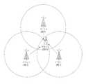
도 1은 기지국을 제어하는 시스템이 클러스터를 구성하는 것을 나타낸 도면이다.1 is a diagram showing a system for controlling a base station configures a cluster.
도 1을 참조하면, 우선 각 단말은 각 인접 기지국으로부터 해당 단말로의 간섭량을 측정하여 일정 기간 동안 평균을 내고 이를 기지국 제어 시스템에 전송한다. 기지국 제어 시스템은 전송된 정보를 이용하여 상호 간섭량이 많아 CoMP를 사용할 경우 성능 향상이 가장 클 것으로 예상되는 기지국들을 모아 클러스터를 구성한다. 하나의 클러스터 내의 기지국의 개수는 변할 수 있으며 또한 각기 다른 클러스터는 기지국의 개수가 서로 다를 수 있다. 도 1에서는 하나의 클러스터가 3개의 기지국으로 구성된다.Referring to FIG. 1, first, each terminal measures an interference amount from each neighboring base station to the corresponding terminal, averages it for a predetermined period, and transmits the averaged amount to the base station control system. The base station control system uses the transmitted information to form a cluster by collecting the base stations expected to have the greatest performance improvement when using CoMP due to the large amount of mutual interference. The number of base stations in one cluster may vary, and different clusters may have different numbers of base stations. In FIG. 1, one cluster is composed of three base stations.
도 2는 단말이 클러스터를 구성하는 것을 나타낸 도면이다.2 is a diagram illustrating a terminal configuring a cluster.
도 2를 참조하면, 단말 1 및 단말 2는 각각 인접 기지국으로부터 해당 단말 로의 간섭량을 측정하여 일정 기간 동안 평균을 낸다. 이에 기초하여 상호 간섭량이 많아 CoMP를 사용할 경우 성능 향상이 가장 클 것으로 예상되는 기지국들을 모아 클러스터를 직접 구성하고, 구성된 클러스터 정보를 기지국 제어 시스템과 교환한다. 도 2는 도 1과 마찬가지로 하나의 클러스터가 3개의 기지국으로 구성된다고 가정하였으며, 실제로 하나의 클러스터에 속하는 기지국의 개수는 변할 수 있다. 또한, 각기 다른 클러스터마다 서로 다른 기지국 개수를 가질 수 있다.Referring to FIG. 2, the
기지국 제어 시스템만이 클러스터를 구성하는 경우에, 기지국 제어 시스템은 단말이 이동에 따른 각 클러스터의 데이터 전송량의 변화를 반영하여 새로운 클러스터를 간헐적으로 구성한다. 그러나, 이와 같이 기지국 제어 시스템만이 네트워크 내의 모든 클러스터를 구성하고 관리하는 경우에는 CoMP를 사용하여 얻을 수 있는 성능 향상 정도에 한계가 있다.When only the base station control system constitutes a cluster, the base station control system intermittently configures a new cluster by reflecting a change in the amount of data transmission of each cluster as the terminal moves. However, when only the base station control system configures and manages all clusters in the network, there is a limit to the degree of performance improvement that can be obtained using CoMP.
또한, 단말(예를 들어 단말 1 및 단말 2)만이 클러스터를 구성하는 경우에, 단말 1 및 단말 2는 각각 단말의 이동에 따른 클러스터 변화에 대한 정보를 특정 영역의 자원을 할당하여 기지국으로 전송할 수 있다. 이때, 각 단말 간의 자원 할당 영역이 중첩될 수 있으므로 각 단말 간에 긴밀한 협력이 필요하다. 또한, 이와 같이 단말만이 클러스터를 구성하는 경우에는 스케줄링 오버헤드가 심각하게 커진다는 문제가 있다.In addition, when only the terminal (for example,
단말이 이동함에 따라 핸드오프할 상황이 생길 수 있다. 핸드오프(hand-off)는 단말이 서비스중인 기지국(셀 또는 섹터) 영역을 벗어나 다른 기지국(셀 또는 섹터)으로 이동을 할 때, 계속 통화를 유지하기 위해 통화로를 이동한 셀로 바꾸어 주는 것을 말한다. 핸드오프는 크게 기존의 통화하던 회선을 먼저 끊은 뒤 새로운 기지국으로 연결하는 방식인 하드 핸드오프(Hard Hand-off) 방식과, 이와 달리 CDMA(Code Division Multiple Access) 방식의 두 개의 기지국(셀 또는 섹터)과 통화로를 유지할 수 있는 기능인 소프트 핸드오프(Soft Hand-off) 방식으로 나눌 수 있다.As the terminal moves, a situation in which the handoff may occur may occur. Hand-off is when a terminal moves out of a serving base station (cell or sector) area to another base station (cell or sector), and changes a call path to a moved cell in order to keep a call. . Handoff is a method of two handsets (cell or sector), which is different from the hard hand-off method in which an existing circuit is disconnected first and then connected to a new base station. ) And soft hand-off.
일반적으로 단말은 핸드오프를 위하여 시스템 내의 셀 ID(IDentity)를 분류하고 관리할 수 있다. 이를 간단히 살펴보면 다음과 같다. 활성 집합(Active Set)은 순방향 데이터 채널이 할당된 셀들이다. 즉 현재 통화하고 있는 셀들을 말한다. 후보 집합(Candidate Set)은 현재 활성 집합(Active set)은 아니지만 충분한 전계 강도를 가지는 셀들이다. 이웃 집합(Neighbor Set)은 충분히 후보 집합이 될 수 있는 셀 들로 이웃 리스트 메시지를 통해 알려진 주변 셀 들을 말한다. 잔여 집합(Remaining Set)은 그 외 셀 들을 말한다.In general, the terminal may classify and manage a cell ID in the system for handoff. This is briefly described as follows. Active sets are cells to which a forward data channel is assigned. That is, the cells that are currently talking. Candidate sets are cells that are not currently active sets but have sufficient field strength. A neighbor set refers to neighbor cells known through a neighbor list message as cells that can be sufficiently candidate sets. Remaining Set refers to other cells.
단말이 상기 분류 기준에 대하여 T_ADD, T_DROP, T_COMP, T_TDROP의 임계 값들을 이용한다. T_ADD는 이웃 집합에서 후보 집합이 되기 위한 기준값이다. T_DROP는 활성 집합에서 T_TDROP 이 동작하는 기준점이고, T_COMP는 활성 집합과 비교하는 기준값이다. 마지막으로, T_TDROP는 T_DROP 이하로 떨어질 때 동작하는 타이머이다. 이하에서 종래의 단말의 핸드오프하는 과정에 대해 살펴본다.The terminal uses threshold values of T_ADD, T_DROP, T_COMP, and T_TDROP with respect to the classification criteria. T_ADD is a reference value for becoming a candidate set in a neighbor set. T_DROP is a reference point at which T_TDROP operates in the active set, and T_COMP is a reference value compared with the active set. Finally, T_TDROP is a timer that runs when it falls below T_DROP. Hereinafter, a process of handing off a conventional terminal will be described.
도 3은 단말 1이 기지국 1, 기지국 2 및 기지국 3 간의 핸드오프 하는 상황을 나타낸 도면이다.FIG. 3 is a diagram illustrating a situation in which UE 1 performs handoff between
도 3을 참조하면, 기지국 1로부터 데이터 채널을 할당받아 기지국 1과 데이 터 통신하고 있던 단말 1이 기지국 1과 기지국 2 간의 핸드오프 영역으로 진입한다고 가정한다. 즉, 단말 1의 활성 집합은 기지국 1이고, 나머지 셀 들은 이웃 집합에 속한다고 가정한다.Referring to FIG. 3, it is assumed that
이때, 기지국 2로부터의 전계 강도가 T_ADD 값보다 클 경우, 기지국 2를 이웃 집합에서 후보 집합으로 전환하기 위해서 단말 1은 기지국 1에 파일럿 세기 측정 메시지(PSMM: Pilot Strength Measurement Message) 등을 통해 각 기지국으로부터의 전계 강도에 대한 정보를 전송한다. 기지국 1은 핸드오프 수행 명령 메시지(HDM: Handoff Direction Message)를 단말 1에 전송하여 기지국 2의 후보 집합 편입을 확정한다.In this case, when the electric field strength from the
그 후, 기지국 2로부터의 전계 강도가 활성 집합에 비해 T_COMP 값보다 크다면, 단말 1은 기지국 2를 후보 집합에서 활성 집합으로 전환하기 위해서 파일럿 세기 측정 메시지를 기지국 1에 전송하고 기지국 1 및 기지국 2는 핸드오프 수행 명령 메시지를 통해 기지국 2의 활성 집합 편입을 확정한다. 이제 활성 집합은 기지국 1 및 기지국 2로 구성되고, 단말 1이 기지국 1 및 기지국 2로부터 데이터 채널을 을 결합하여 수신할 수 있게 된다.Then, if the electric field strength from the
그 후, 단말 1이 점차 기지국 2 쪽으로 이동하여 기지국 1로부터의 전계 강도가 T_DROP 값보다 낮아지면 T_TDROP 타이머가 작동하기 시작하여 T_TDROP 타이머가 만료되고 기지국 1로부터의 전계 강도가 T_DROP 값보다 낮을 경우, 기지국 1을 활성 집합에서 이웃 집합으로 전환하고, 기지국 1에서 기지국 2로의 핸드오프를 완료하게 된다.After that, when the
이제, 단말 1이 기지국 1 및 기지국 2로부터 동시에 데이터를 수신하고 있고, 점차 기지국 3 쪽으로 이동한다고 가정한다. 기지국 3으로부터의 수신 전계 강도가 점차 커지게 되어 T_ADD 값보다 클 경우, 기지국 3을 이웃 집합에서 후보 집합으로 전환하기 위해서 단말 1은 기지국 1 및 기지국 2로 파일럿 세기 측정 메시지를 전송한다. 기지국 1 및 기지국 2는 핸드오프 수행 명령 메시지 단말 1에 전송하여 기지국 3의 후보 집합편입을 확정한다.Now, it is assumed that
다시 기지국 3으로부터의 전계 강도가 활성 집합에 비해 T_COMP 값보다 클 경우, 단말 1은 기지국 3을 후보 집합에서 활성 집합으로 전환하기 위해서 파일럿 세기 측정 메시지를 기지국 1과 기지국 2에 전송하고 기지국 1 및 기지국 2는 핸드오프 수행 명령 메시지를 통해 기지국 3의 활성 집합 편입을 확정한다. 이제 활성 집합은 기지국 1, 기지국 2, 기지국 3으로 구성되고 단말 1은 기지국 1, 기지국 2, 기지국 3으로부터 데이터 채널을 결합 수신할 수 있게 된다.Again, if the field strength from
그 후, 단말이 점차 기지국 3 쪽으로 더 이동해 가면, 결국 기지국 3만이 활성 집합이 될 것이다. 그러나, 기지국 3의 자원 할당 상황을 고려할 때, 오히려 기지국 3의 핸드오프 수행하는 것이 힘들 수 있다. 이와 같이, 종래의 핸드오프는 각 기지국의 파일럿 세기 측정에만 기초해 결정됨으로써 문제가 있었다. 이와 같이, 종래에는 하나의 기지국으로 핸드오프하는 경우에 대해서만 기술하고 있다.After that, if the terminal gradually moves further toward
또한, 각 단말이 여러 가지의 CoMP 방식 중에서 현재 단말의 상황에 적절한 CoMP 방식을 선택하는 방법에 대해 아직까지 정의된 바가 없다.In addition, the method for selecting a CoMP method suitable for the situation of the current terminal among the various CoMP methods is not defined yet.
본 발명이 이루고자 하는 기술적 과제는 단말이 적응적으로 CoMP 방식을 선택하는 방법을 제공하는 데 있다.An object of the present invention is to provide a method for the UE to adaptively select the CoMP scheme.
본 발명에서 이루고자 하는 기술적 과제들은 상기 기술적 과제로 제한되지 않으며, 언급하지 않은 또 다른 기술적 과제들은 아래의 기재로부터 본 발명이 속하는 기술분야에서 통상의 지식을 가진 자에게 명확하게 이해될 수 있을 것이다.The technical problems to be solved by the present invention are not limited to the technical problems and other technical problems which are not mentioned can be understood by those skilled in the art from the following description.
상기의 기술적 과제를 달성하기 위한, 본 발명에 따른 단말의 적응적 CoMP 방식 선택 방법은, 상기 단말이 제 1 CoMP(Coordinate Multi-Point) 방식을 수행하는 동안 각 CoMP 세트 중 수신신호 대 간섭 및 잡음 비(SINR: Signal to Interference plus Noise Ratio)를 최대화할 수 있는 제 1 CoMP 세트를 선택하는 단계; 상기 단말이 상기 제 1 CoMP 세트와 상기 제 1 CoMP 방식을 수행하는 동안 현재 자신의 데이터 전송률와 요구되는 최소 데이터 전송률을 비교하는 단계; 및 상기 제 1 CoMP 방식을 수행하는 단말이 상기 비교 결과에 기초하여 사전에 설정된 CoMP(Coordinate Multi-Point) 방식 순서에 따라 제 2 CoMP 방식을 선택하는 단계를 갖는다.In order to achieve the above technical problem, the adaptive CoMP method selection method of the terminal according to the present invention, the received signal versus interference and noise of each CoMP set while the terminal performs the first CoMP (Coordinate Multi-Point) method Selecting a first CoMP set capable of maximizing a Signal to Interference plus Noise Ratio (SINR); Comparing, by the terminal, the current data rate and the required minimum data rate while the first CoMP set and the first CoMP scheme are performed; And selecting, by the terminal performing the first CoMP scheme, the second CoMP scheme according to a preset CoMP (Coordinate Multi-Point) scheme order based on the comparison result.
또한, 본 발명에 따른 단말의 적응적 CoMP 방식 선택 방법은, 상기 단말이 상기 제 2 CoMP 방식을 수행하는 동안 상기 각 CoMP 세트 중 수신신호 대 간섭 및 잡음 비를 최대화할 수 있는 제 2 CoMP 세트를 선택하는 단계를 더 포함하는 것이 바람직하다.In addition, the adaptive CoMP scheme selection method of the terminal according to the present invention, the second CoMP set of the CoMP set of each of the CoMP set during the second CoMP scheme can maximize the CoMP set of the interference and noise ratio It is preferable to further include the step of selecting.
상기의 또 다른 기술적 과제를 달성하기 위한, 본 발명에 따른 서빙 기지국이 CoMP 방식 선택을 수행하는 소정 네트워크 엔티티(Network Entity)를 위한 정보를 제공하는 방법은, 상기 서빙 기지국이 단말로부터 상기 단말의 현재 데이터 전송률이 최소 요구 데이터 전송률을 충족하지 못하였음을 나타내는 메시지를 수신하는 단계; 상기 서빙 기지국이 상기 단말로 채널 상태 정보 요구 지시자를 전송하는 단계; 상기 서빙 기지국이 상기 단말로부터 비주기적 제어 채널을 통하여 수신신호 대 간섭 잡음 비 정보를 포함하는 채널 상태 정보를 수신하는 단계; 및 상기 수신된 채널 상태 정보를 상기 네트워크 엔티티에 전송하는 단계를 갖는다.In order to achieve the above technical problem, a method for providing information for a predetermined network entity in which a serving base station according to the present invention performs a CoMP scheme selection is provided. Receiving a message indicating that the data rate did not meet the minimum required data rate; Transmitting, by the serving base station, a channel state information request indicator to the terminal; Receiving, by the serving base station, channel state information including received signal-to-interference noise ratio information from the terminal through an aperiodic control channel; And transmitting the received channel state information to the network entity.
본 발명에 따른 단말의 적응적 CoMP 방식 선택 방법은 여러 가지의 장점이 있다.The adaptive CoMP method selection method of the terminal according to the present invention has various advantages.
단말은 현재 자신의 데이터 전송률과 요구되는 최소 데이터 전송률을 비교하여 현재 상황에 적절한 CoMP 방식을 선택할 수 있다.The UE may select a CoMP scheme suitable for the current situation by comparing its current data rate with the required minimum data rate.
단말이 이러한 적절한 CoMP 방식을 선택함으로써 데이터 전송률 및 처리량이 상당히 개선될 수 있다.The data rate and throughput can be significantly improved by the UE selecting such a suitable CoMP scheme.
본 발명에서 얻은 수 있는 효과는 이상에서 언급한 효과들로 제한되지 않으며, 언급하지 않은 또 다른 효과들은 아래의 기재로부터 본 발명이 속하는 기술분야에서 통상의 지식을 가진 자에게 명확하게 이해될 수 있을 것이다.Effects obtained in the present invention are not limited to the above-mentioned effects, and other effects not mentioned above may be clearly understood by those skilled in the art from the following description. will be.
이하 본 발명에 따른 바람직한 실시형태들을 첨부된 도면을 참조하여 상세하게 설명한다. 첨부된 도면과 함께 이하에 개시되는 상세한 설명은 본 발명의 예시적인 실시형태를 설명하고자 하는 것이며, 본 발명이 실시될 수 있는 유일한 실시형태를 나타내고자 하는 것이 아니다. 이하의 상세한 설명은 본 발명의 완전한 이해를 돕기 위해 구체적인 세부사항을 포함한다. 그러나, 당업자는 본 발명이 이러한 구체적 세부사항 없이도 실시될 수 있음을 알 수 있다. 예를 들어, 이하의 설명에서 일정 용어를 중심으로 설명하나, 이들 용어에 한정될 필요는 없으며 임의의 용어로서 지칭되는 경우에도 동일한 의미를 나타낼 수 있다. 또한, 본 명세서 전체에서 동일하거나 유사한 구성요소에 대해서는 동일한 도면 부호를 사용하여 설명한다.Hereinafter, exemplary embodiments of the present invention will be described in detail with reference to the accompanying drawings. The detailed description set forth below in conjunction with the appended drawings is intended to explain exemplary embodiments of the present invention and is not intended to represent the only embodiments in which the present invention may be practiced. The following detailed description includes specific details to assist in a thorough understanding of the present invention. However, one of ordinary skill in the art appreciates that the present invention may be practiced without these specific details. For example, the following description will focus on certain terms, but need not be limited to these terms and may refer to the same meaning even when referred to as any term. In addition, the same or similar components throughout the present specification will be described using the same reference numerals.
명세서 전체에서, 어떤 부분이 어떤 구성요소를 "포함"한다고 할 때, 이는 특별히 반대되는 기재가 없는 한 다른 구성요소를 제외하는 것이 아니라 다른 구성요소를 더 포함할 수 있는 것을 의미한다.Throughout the specification, when a part is said to "include" a certain component, it means that it can further include other components, without excluding other components unless specifically stated otherwise.
이하에 개시되는 기술은 다양한 통신 시스템에 사용될 수 있는데, 이러한 통신 시스템은 음성, 패킷 데이터 등과 같은 다양한 통신 서비스를 제공할 수 있다. 통신 시스템의 기술은 하향링크(Downlink) 또는 상향링크(Uplink)에 사용될 수 있다. 기지국은 고정국(fixed station), Base Station, Node B, eNode B(eNB), 액세스 포인트(access point), ABS 등의 용어에 의해 대체될 수 있다. 또한, 단말(MS: Mobile Station)은 UE(User Equipment), SS(Subscriber Station), MSS(Mobile Subscriber Station), AMS 또는 Mobile Terminal 등의 용어로 대체될 수 있다.The technique disclosed below may be used in various communication systems, which may provide various communication services such as voice, packet data, and the like. The technology of the communication system can be used for downlink or uplink. A base station may be replaced by terms such as a fixed station, a base station, a Node B, an eNode B (eNB), an access point, an ABS, and the like. In addition, a mobile station (MS) may be replaced with terms such as a user equipment (UE), a subscriber station (SS), a mobile subscriber station (MSS), an AMS, or a mobile terminal.
또한, 송신단은 데이터 또는 음성 서비스를 전송하는 노드를 말하고, 수신단은 데이터 또는 음성 서비스를 수신하는 노드를 의미한다. 따라서, 상향링크에서는 단말이 송신단이 되고, 기지국이 수신단이 될 수 있다. 마찬가지로, 하향링크에서는 단말이 수신단이 되고, 기지국이 송신단이 될 수 있다.In addition, the transmitting end refers to a node transmitting data or voice service, and the receiving end refers to a node receiving data or voice service. Therefore, in uplink, a terminal may be a transmitting end and a base station may be a receiving end. Similarly, in downlink, a terminal may be a receiving end and a base station may be a transmitting end.
한편, 본 발명의 단말로는 PDA(Personal Digital Assistant), 셀룰러폰, PCS(Personal Communication Service)폰, GSM(Global System for Mobile)폰, WCDMA(Wideband CDMA)폰, MBS(Mobile Broadband System)폰 등이 이용될 수 있다.On the other hand, the terminal of the present invention PDA (Personal Digital Assistant), cellular phone, PCS (Personal Communication Service) phone, GSM (Global System for Mobile) phone, WCDMA (Wideband CDMA) phone, MBS (Mobile Broadband System) phone This can be used.
본 발명의 실시예들은 무선 접속 시스템들인 IEEE(Institute of Electrical and Electronics Engineers) 802 시스템, 3GPP 시스템, 3GPP LTE 시스템 및 3GPP2 시스템 중 적어도 하나에 개시된 표준 문서들에 의해 뒷받침될 수 있다. 즉, 본 발명의 실시예들 중 본 발명의 기술적 사상을 명확히 드러내기 위해 설명하지 않은 단계들 또는 부분들은 상기 문서들에 의해 뒷받침될 수 있다. 또한, 본 문서에서 개시하고 있는 모든 용어들은 상기 표준 문서에 의해 설명될 수 있다. 특히, 본 발명의 실시예들은 3GPP 및 3GPP2 시스템의 표준 문서인 TS25, TS36 시리즈 및 C.S000x 시리즈 등의 문서에 의해 뒷받침될 수 있다.Embodiments of the present invention may be supported by standard documents disclosed in at least one of the Institute of Electrical and Electronics Engineers (IEEE) 802 system, the 3GPP system, the 3GPP LTE system, and the 3GPP2 system, which are wireless access systems. That is, steps or parts which are not described to clearly reveal the technical spirit of the present invention among the embodiments of the present invention may be supported by the above documents. In addition, all terms disclosed in the present document can be described by the above standard document. In particular, embodiments of the present invention may be supported by documents such as TS25, TS36 series and C.S000x series, which are standard documents of 3GPP and 3GPP2 systems.
이하의 설명에서 사용되는 특정(特定) 용어들은 본 발명의 이해를 돕기 위해서 제공된 것이며, 이러한 특정 용어의 사용은 본 발명의 기술적 사상을 벗어나지 않는 범위에서 다른 형태로 변경될 수 있다.Specific terms used in the following description are provided to help the understanding of the present invention, and the use of the specific terms may be modified in other forms without departing from the technical spirit of the present invention.
본 발명에서 기지국은 셀 또는 섹터를 포함하는 개념으로 사용될 수 있다. 또한, 본 발명에서 단말, 기지국, 기지국 제어 시스템은 무선 네트워크를 구성하고 있으며 내부 인터페이스 또는 백본망 등을 통하여 연결되어 있다.In the present invention, the base station may be used as a concept including a cell or a sector. In the present invention, the terminal, the base station, the base station control system constitutes a wireless network and is connected through an internal interface or a backbone network.
기지국 제어 시스템은 서빙 기지국 및 협력 기지국의 상위 기능을 수행하고, 데이터 및 제어 정보 전달을 통제하는 시스템에 해당한다. 이러한 기지국 제어 시스템은 일반적으로 하나의 네트워크 엔티티(entity)라고 할 수 있다. 서빙 기지국(셀)은 단말에게 기존의 주요 서비스를 제공하는 기지국으로 볼 수 있고, 협력 다중 전송 포인트 상에서의 제어 정보의 전송 및 수신을 수행할 수 있다. 이러한 의미에서 서빙 기지국은 앵커 기지국(셀)(anchor cell)이라 칭할 수 있다.The base station control system corresponds to a system that performs higher functions of the serving base station and the cooperative base station and controls the transmission of data and control information. Such a base station control system may generally be referred to as one network entity. The serving base station (cell) may be regarded as a base station providing existing main services to the terminal, and may perform transmission and reception of control information on a cooperative multiple transmission point. In this sense, the serving base station may be referred to as an anchor base station (cell).
CoMP(Coordinate Multi-Point) 시스템은 다중 셀 환경에서 개선된 MIMO 전송을 적용함으로써 셀 경계에 있는 사용자의 처리량을 개선할 수 있다. CoMP 시스템을 적용하면 다중 셀 환경에서 셀 간 간섭(Inter-Cell Interference)을 줄일 수 있고, 단말은 다중-셀 기지국(Multi-cell base-station)으로부터 공동으로 데이터를 지원받을 수 있다. 또한, 각 기지국은 동일한 무선 주파수 자원(Same Radio Frequency Resource)을 이용하여 하나 이상의 단말(MS 1, MS 2, … MS K)에 동시에 지원함으로써 시스템의 성능을 향상시킬 수 있다. 그리고, 기지국은 기지국 및 단말 간의 채널상태정보에 기초하여 공간 분할 다중접속(SDMA: Space Division Multiple Access) 방법을 수행할 수 있다.CoMP (Coordinate Multi-Point) systems can improve throughput for users at cell boundaries by applying improved MIMO transmission in a multi-cell environment. By applying the CoMP system, inter-cell interference may be reduced in a multi-cell environment, and the terminal may be jointly supported with data from a multi-cell base station. In addition, each base station can improve the performance of the system by simultaneously supporting one or more terminals (
CoMP 시스템에서, 서빙 기지국 및 하나 이상의 협력 기지국들은 백본망(Backbone Network)을 통해 스케줄러(scheduler)에 연결될 수 있다. 스케줄러는 백본망을 통하여 각 기지국(기지국 1, 기지국 2, … 기지국 M)이 측정한 각 단말(MS 1, MS 2, … MS K) 및 협력 기지국 간의 채널 상태에 관한 채널 정보를 피드 백 받아 동작할 수 있다. 예를 들어, 스케줄러는 서빙 기지국 및 하나 이상의 협력 기지국에 대하여 협력적 MIMO 동작을 위한 정보를 스케줄링할 수 있다. 즉 스케줄러에서 각 기지국으로 협력적 MIMO 동작에 대한 지시를 직접 할 수 있다.In a CoMP system, the serving base station and one or more cooperative base stations may be connected to a scheduler via a backbone network. The scheduler operates by receiving back channel information on the channel status between each terminal (
CoMP 시스템에서, 특정 단말과 동일한 기지국을 기반으로 하고 있는 셀 들은 내부 인터페이스 또는 x2 인터페이스를 통해 정보(예를 들어 데이터, 채널상태정보(CSI: Channel State Information)를 주고 받을 수 있지만, 이와 달리 다른 기지국을 기반으로 하고 있는 셀 들은 백홀 등을 통해서 셀 간 정보를 주고 받을 수 있다.In the CoMP system, cells based on the same base station as a specific terminal may transmit and receive information (for example, data and channel state information (CSI)) through an internal interface or an x2 interface. Cells based on the information may exchange information between cells through a backhaul.
CoMP 방식은 2 이상의 전송 포인트(transmission points)가 서로 협력하여 음영 지역에 있는 단말의 데이터 처리량 및 네트워크의 총 데이터 처리량을 증가시키기 위한 방식이다. 전송 포인트는 릴레이 또는 라우터와 같이 셀의 기지국 또는 다른 전송 안테나 포인트일 수 있다. 전송 포인트의 실제 위치는 동일한 기지국(인트라 기지국(intra-cell site)이거나 또는 다른 기지국(인터 기지국(inter-cell site)일 수 있다.In the CoMP scheme, two or more transmission points cooperate with each other to increase data throughput of a terminal in a shadow area and total data throughput of a network. The transmission point may be a cell's base station or other transmit antenna point, such as a relay or router. The actual location of the transmission point may be the same base station (intra-cell site) or another base station (inter-cell site).
전송 포인트가 인트라 기지국인 경우, 백홀 지연(backhaul delay)이 다른 기지국 배치와 비교해 볼 때 훨씬 더 작기 때문에, 협력 기지국(cell site)을 배치하는 것이 더 가능해진다. CoMP 시스템이 적절하게 동작하기 위해서는 셀들이 클러스터의 그룹으로 분할될 필요가 있다. 만약, 셀들이 클러스터로 분할되지 않는다면, 네트워크 엔티티에 의한 하향링크 데이터의 스케줄링이 전체 네트워크에 대해 실행되기 때문에, 백홀의 총 오버헤드의 양이 상당히 클 수 있다. 따라서, 셀이 적절하 게 클러스터로 분할될 필요가 있다. 이하에서 CoMP 클러스터를 구성하는 방법에 대해 살펴본다.If the transmission point is an intra base station, it is possible to deploy a cooperative cell site since the backhaul delay is much smaller compared to other base station deployments. In order for the CoMP system to work properly, the cells need to be divided into groups of clusters. If the cells are not divided into clusters, the amount of total overhead in the backhaul can be quite large because scheduling of downlink data by the network entity is performed for the entire network. Therefore, the cell needs to be appropriately divided into clusters. Hereinafter, a method of configuring a CoMP cluster will be described.
각 단말 주변에 있는 전송 포인트들은 다음과 같은 5개의 카테고리로 구분할 수 있다.Transmission points around each terminal may be classified into the following five categories.
CoMP 활성 포인트 집합(CAPS: CoMP Active Point Set, 이하 CAPS라 한다)은 특정 단말을 서빙하고 실제로 CoMP 전송이 수행되는 전송 포인트 집합으로서, 종래 클러스터에서 활성 집합에 대응하는 개념이다. CoMP 협력 포인트 집합(CCPS: CoMP Coordinated Point Set, 이하 CCPS라 한다)은 특정 단말을 서빙하며 실제로 CoMP 협력 스케줄링이 수행되는 전송 포인트 집합으로서, 종래의 클러스터에서 후보 집합에 대응하는 개념의 집합이다.A CoMP Active Point Set (CAPS: CAPS) is a set of transmission points for serving a specific UE and actually performing CoMP transmission, and is a concept corresponding to an active set in a conventional cluster. CoMP Coordinated Point Set (CCPS: CoMP Coordinated Point Set (CCPS)) is a set of transmission points that serve a specific UE and actually perform CoMP cooperative scheduling, and is a set of concepts corresponding to candidate sets in a conventional cluster.
그리고, CoMP 보고 포인트 집합(CRPS: CoMP Report Point Set, 이하 CRPS라 한다)은 특정 단말에 의해 네트워크로 파일럿 신호 세기 측정 메시지 등을 통해 송수신단 간의 채널 상태가 보고되는 전송 포인트 집합을 말한다. CoMP 측정 포인트 집합(CMPS: CoMP Measurement Point Set, 이하 CMPS라 한다)은 특정 단말이 파일럿 신호 세기 등의 송수신단 간의 채널 상태를 측정하고 있는 전송 포인트 집합으로서, 종래 클러스터에서 이웃 집합에 대응하는 개념의 집합이다. CoMP 네트워크 클러스터링 집합(CNCS: CoMP Network Clustering Set, 이하 CNCS라 한다)은 데이터 전송 스케줄링이 수행되는 전송 포인트 집합을 말하고, 이는 네트워크가 스스로 구성한 클러스터의 집합을 나타낸다. 이 CoMP 네트워크 클러스터링 집합 내에서는 단말이 클러스터를 구성하고 관리할 수 있다.The CoMP Report Point Set (CRPS) refers to a transmission point set in which channel states between a transmitting and receiving end are reported by a specific terminal through a pilot signal strength measurement message to a network. A CoMP Measurement Point Set (CMPS) is a set of transmission points in which a specific terminal measures a channel state between a transmitter and a receiver, such as pilot signal strength, and has a concept corresponding to a neighbor set in a conventional cluster. It is a set. The CoMP Network Clustering Set (CNCS) refers to a set of transmission points on which data transmission scheduling is performed, and represents a set of clusters configured by the network itself. In this CoMP network clustering set, a terminal can configure and manage a cluster.
협력 스케줄링/빔포빙(CoMP-CS/CB) 방식의 경우에, 다른 셀 들로부터 생성되는 간섭을 제어하는 협력스케줄링 결정을 하기 위한 셀 집합은 CCPS 내의 셀들이다. 이때, 실제로 데이터는 서빙 셀로부터만 전송되기 때문에, CoMP-CS/CB 방식인 경우에 CAPS의 크기는 항상 1이다.In the case of CoMP-CS / CB scheme, the cell set for making cooperative scheduling decision to control the interference generated from other cells is cells in CCPS. In this case, since data is actually transmitted only from the serving cell, the size of CAPS is always 1 in the case of CoMP-CS / CB.
종래에 조인트 프로세싱(CoMP-JP) 방식은 각 전송 포인트들이 실제로 데이터 채널을 할당하여 데이터를 전송하는 방식으로 정의되었다. 그러나, 조인트 프로세싱 방식(CoMP-JP)을 수행하는 모든 전송 포인트들이 데이터를 전송하는 경우에 백홀 데이터가 상당하게 커지는 문제가 발생하기 때문에 새롭게 조인트 프로세싱(CoMP-JP) 방식을 정의하는 것이 바람직하다.In the related art, joint processing (CoMP-JP) has been defined in which each transmission point actually allocates a data channel to transmit data. However, since all the transmission points performing the joint processing scheme (CoMP-JP) transmit data, a problem arises in that the backhaul data becomes considerably large. Therefore, it is preferable to newly define the joint processing (CoMP-JP) scheme.
본 발명에서는 전송 포인트들이 데이터 채널을 할당하여 실제로 데이터를 전송하고 있지 않더라도 각각의 전송 포인트에서 데이터가 이용가능(available) 하다면 조인트 프로세싱(CoMP-JP) 방식을 수행한다고 정의할 수 있다. 따라서, 각 전송 포인트에서 데이터는 이용가능 하지만, 실제 전송은 특정 시점에 바람직한 하나의 전송 포인트로부터 일어날 수 있는 동적 셀 선택(Dynamic Cell Selection)의 경우는 조인트 프로세싱(CoMP-JP) 방식이라고 정의할 수 있다.In the present invention, even if the transmission points allocate data channels and do not actually transmit data, the data may be defined as performing joint processing (CoMP-JP) if data is available at each transmission point. Thus, data may be available at each transmission point, but in the case of dynamic cell selection, where actual transmission may occur from one desired transmission point at a particular point of time, it may be defined as a joint processing (CoMP-JP) scheme. have.
동적 셀 선택은 고속 셀 선택(Fast Cell Selection)과 유사한 개념에 해당한다. 핸드오프를 위하여 별도의 무선 자원을 할당해야 함과 동시에 잦은 핸드오프가 발생되는 경우에는 시스템의 부하를 증가시키는 문제가 발생할 수 있다. 이러한 단점을 극복하고 이동 환경에서 지속적인 패킷 서비스를 제공하기 위한 것이 고속 셀 선택이다. 고속 셀 선택 알고리즘은 패킷 서비스를 위하여 활성 집합에 있는 셀 중 에서 무선 환경뿐만 아니라 전력과 코드 스페이스 면에서 최선의 셀을 선택하여 서비스를 제공하기 위한 방식이다.Dynamic cell selection corresponds to a concept similar to fast cell selection. In addition to allocating a separate radio resource for handoff and frequent handoff, a problem may occur that increases the load on the system. In order to overcome these disadvantages and provide continuous packet service in a mobile environment, fast cell selection is required. The fast cell selection algorithm is a method for selecting a best cell in terms of power and code space as well as a wireless environment among cells in an active set for packet service.
조인트 프로세싱(CoMP-JP) 방식의 경우에, 단말로 데이터를 전송하는 다중 전송 포인트들은 CoMP 활성 포인트 집합(CAPS)의 셀들이다. CoMP 활성 포인트 집합(CAPS)은 데이터가 실제로 전송되고 있는 전송 포인트로 구성된다. 따라서, 조인트 프로세싱의 경우에 CoMP 활성 포인트 집합(CAPS)의 크기는 1 이상이다. CoMP 활성 포인트 집합(CAPS)는 CoMP 협력 포인트 집합(CCPS)의 하위 집합(subset)이고, CoMP 활성 포인트 집합(CAPS), CoMP 협력 포인트 집합(CCPS), CoMP 보고 포인트 집합(CRPS), CoMP 측정 포인트 집합(CMPS)의 크기는 다음의 수학식 1을 만족한다.In the case of a joint processing (CoMP-JP) scheme, the multiple transmission points for transmitting data to the terminal are cells of a CoMP Active Point Set (CAPS). The CoMP Active Point Set (CAPS) consists of transmission points where data is actually being transmitted. Thus, in the case of joint processing, the size of the CoMP Active Point Set (CAPS) is greater than one. CoMP Active Point Set (CAPS) is a subset of CoMP Cooperative Point Set (CCPS), CoMP Active Point Set (CAPS), CoMP Cooperative Point Set (CCPS), CoMP Reporting Point Set (CRPS), CoMP Measurement Point The size of the set CMPS satisfies
여기서, CoMP 활성 포인트 집합(CAPS), CoMP 협력 포인트 집합(CCPS), CoMP 보고 포인트 집합(CRPS) 및 CoMP 측정 포인트 집합(CMPS)는 특정 단말에 대해 정의된 것임을 유의할 필요가 있다. 반면에, CoMP 네트워크 클러스터링 집합(CNCS)는 네트워크에 의해 정의될 수 있다.Here, it is to be noted that CoMP Active Point Set (CAPS), CoMP Cooperative Point Set (CCPS), CoMP Report Point Set (CRPS), and CoMP Measurement Point Set (CMPS) are defined for a specific UE. On the other hand, CoMP Network Clustering Set (CNCS) may be defined by the network.
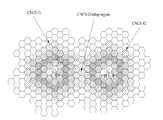
도 4 및 도 5는 CoMP 집합 분류의 일 예를 나타낸 도면이다.4 and 5 are diagrams illustrating an example of CoMP set classification.
도 4 및 도 5에서, 각 전송 포인트는 하나의 셀에 대응하고 각 셀로부터의 신호의 세기는 셀 및 단말 간의 거리에 비례할 수 있다. 여기서, 네트워크는 셀 들을 2개의 CoMP 네트워크 클러스터링 집합(CNCS)로 분할할 수 있고, 단말 1 및 단말 2는 각 CoMP 네트워크 클러스터링 집합(CNCS) 내에 위치하고 있다고 가정한다.4 and 5, each transmission point corresponds to one cell and the strength of the signal from each cell may be proportional to the distance between the cell and the terminal. Here, it is assumed that the network can divide cells into two CoMP network clustering sets (CNCS), and
도 4에서, 2개의 CoMP 네트워크 클러스터링 집합(CNCS) 영역이 상호 서로 배타적이라고 가정한다. 따라서, 데이터 전송 스케줄링은 각 CoMP 네트워크 클러스터링 집합(CNCS) 내에서 수행될 수 있다. 이러한 실시예에 있어서, 단말 1 및 단말 2에 대한 CoMP 활성 포인트 집합(CAPS)의 크기는 3이고, CoMP 협력 포인트 집합(CCPS)에 대한 크기는 9이고, CoMP 보고 포인트 집합(CRPS)의 크기는 15이고, CoMP 측정 포인트 집합(CMPS)에 대한 크기는 21일 수 있다.In FIG. 4, it is assumed that two CoMP network clustering set (CNCS) regions are mutually exclusive with each other. Thus, data transmission scheduling can be performed within each CoMP Network Clustering Set (CNCS). In this embodiment, the size of CoMP Active Point Set (CAPS) for
또한, 선택적으로, 단말 1 및 단말 2에 대한 CoMP 활성 포인트 집합(CAPS)의 크기는 3이고, CoMP 협력 포인트 집합(CCPS)에 대한 크기는 12이고, CoMP 보고 포인트 집합(CRPS)의 크기는 27이고, CoMP 측정 포인트 집합(CMPS)에 대한 크기는 48일 수 있다. 이 경우에, 각 CoMP 포인트 집합의 크기는 상기 해당 CoMP 포인트 집합의 하위 집합의 CoMP 포인트 집합의 크기를 합하여 표현한 것이다.Also, optionally, the size of CoMP Active Point Set (CAPS) for
도 5에서, 제 1 CoMP 네트워크 클러스터링 집합(제 1 CNCS) 및 제 2 CoMP 네트워크 클러스터링 집합(제 2 CNCS) 영역은 상호 간에 배타적이지 않고 일부 영역이 오버래핑될 수 있다. 단말이 제 1 CoMP 네트워크 클러스터링 집합(제 1 CNCS)의 경계 영역 및 제 2 CoMP 네트워크 클러스터링 집합(제 2 CNCS) 영역(즉, CoMP 네트워크 클러스터링 집합(CNCS)간에 오버래핑된 영역)에 위치할 수 있다. 이 상황에서 다른 CNCS로부터의 강한 간섭 신호가 존재함에도 불구하고 제 1 CNCS 및 제 2 CNCS에 걸쳐서 CoMP 동작이 수행될 수 있다는 것이 장점이라 할 수 있다.In FIG. 5, the first CoMP network clustering set (first CNCS) and the second CoMP network clustering set (second CNCS) regions are not mutually exclusive and some regions may overlap. The terminal may be located in the boundary region of the first CoMP network clustering set (first CNCS) and the second CoMP network clustering set (second CNCS) region (that is, the region overlapped between the CoMP network clustering set (CNCS)). In this situation, it can be advantageous that CoMP operation can be performed over the first CNCS and the second CNCS despite the presence of strong interference signals from other CNCS.
CoMP 네트워크 클러스터링 집합(CNCS) 오버랩 영역에서 오버랩을 허용함으로써, CoMP 네트워크 클러스터링 집합(CNCS) 오버랩 영역으로 들어가기 시작하는 단 말은 이제 제 1 CoMP 네트워크 클러스터링 집합(제 1 CNCS) 및 제 2 CoMP 네트워크 클러스터링 집합(제 2 CNCS) 간의 CoMP 동작으로부터 여러 가지 이득을 얻을 수 있다. 이때, 오버래핑된 CoMP 네트워크 클러스터링 집합(CNCS) 영역에서의 자원 스케줄링 협력은 제 1 CoMP 네트워크 클러스터링 집합(제 1 CNCS) 및 제 2 CoMP 네트워크 클러스터링 집합(제 2 CNCS) 영역 간의 결합에 의해 수행됨을 유의할 필요가 있다.By allowing overlap in the CoMP Network Clustering Set (CNCS) overlap area, the terminal beginning to enter the CoMP Network Clustering Set (CNCS) overlap area is now the first CoMP network clustering set (first CNCS) and the second CoMP network clustering set. Various benefits can be obtained from the CoMP operation between the (second CNCS). In this case, it should be noted that resource scheduling cooperation in the overlapped CoMP network clustering set (CNCS) region is performed by combining between the first CoMP network clustering set (first CNCS) and the second CoMP network clustering set (second CNCS) region. There is.
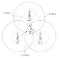
도 6은 단말 1이 기지국 1, 기지국 2 및 기지국 3 간의 CoMP 집합 단위로 핸드오프 하는 상황을 나타낸 도면이다.FIG. 6 is a diagram illustrating a situation in which
도 6을 참조하면, 단말 1이 기지국 1, 기지국 2 및 기지국 3 간에 핸드오프하는 상황에서, 단말 1은 기지국 1 및 기지국 2로부터 동시에 데이터를 수신할 수 있다. 여기서, 단말 1은 최대 2개의 기지국으로부터 동시에 신호를 수신할 수 있다고 가정한다. 기지국 1 및 기지국 2가 제 1 CoMP 집합을 형성하고, 기지국 2 및 기지국 3에 제 2 CoMP 집합을, 기지국 3 및 기지국 1이 제 3 CoMP 집합을 형성한다고 가정한다.Referring to FIG. 6, in a situation where terminal 1 is handing off between
조인트 프로세싱(CoMP-JP) 방식에 대한 CoMP 활성 포인트 집합(CAPS)를 포함할 수 있고, 협력 스케줄링/빔포빙(CoMP-CS/CB) 방식에 대한 CoMP 협력 포인트 집합(CCPS)를 포함할 수 있다. 그리고 기지국 1, 기지국 2, 기지국 3은 모두 CoMP 네트워크 클러스터링 집합(CNCS) 내에 있다. 그리고, 여기서 기지국 1을 단말 1로 핸드오프 수행 결정 메시지(HDM) 또는 채널 할당 메시지(CAM: Channel Assignment Message)과 같은 제어 신호를 전송하는 앵커 셀로 가정한다.It may include a CoMP Active Point Set (CAPS) for a Joint Processing (CoMP-JP) scheme, and may include a CoMP Cooperative Point Set (CCPS) for a Cooperative Scheduling / beamfobbing (CoMP-CS / CB) scheme. .
단말 1이 점차 기지국 3 쪽으로 이동할 경우, 기지국 3으로부터의 수신 전계 강도가 점차 커지게 된다. 기지국 3으로부터의 전계 강도가 T_ADD 값 보다 커질 경우, 단말 1은 기지국 1 및 기지국 2로 파일럿 세기 측정 메시지(PSMM: Pilot Strength Measurement Message)를 전송할 수 있다. 이때, 단말이 기존 핸드오프 방식대로 각 기지국 간의 CoMP를 수행할 것인지 여부를 고려하지 않고 파일럿 세기 측정 메시지를 전송하면, 기지국 제어 시스템은 전체적인 자원 할당 상황까지 고려하여 각 기지국 간의 CoMP 수행 여부를 결정하는 데 있어서 충분한 정보를 갖지 못할 수 있다.When the
예를 들어, 기지국 3의 현재 자원 할당 상 주변의 기지국 1 또는 기지국 2와의 CoMP 수행이 힘들 경우에는 단말 1의 입장에서 기지국 3으로 핸드오프를 수행하는 대신에 기지국 1 및 기지국 2의 제 1 CoMP 집합을 유지하는 것이 바람직할 수 있다. 만약, 종래의 방식대로 핸드오프를 수행한다면, 단말 1은 각 기지국 1, 기지국 2, 기지국 3으로부터의 수신 전계 강도를 비교하여 기지국 3으로 핸드오프가 이루어질 수 있다. 따라서, 단말 1이 기지국 3으로의 핸드오프 시 발생할 수 있는 이러한 문제점을 해결하기 위한 최적의 CoMP 집합을 만들기 위해 개선된 핸드오프 방식이 요구된다. 이하에서 개선된 핸드오프 방식에 대해 살펴본다.For example, if it is difficult to perform CoMP with neighboring
단말 1은 기지국 3 및 기지국 1(또는 기지국 2, 이하에서는 기지국 1의 경우만을 고려한다)와 수행할 CoMP 방식에 대해 현재 알고 있지 못할 수 있다. 따라서, 단말 1은 기지국 3으로 기지국 3 및 기지국 1이 수행할 CoMP 방식을 가정하여 각 CoMP 방식에 적합한 정보를 기지국 3으로 전송할 수 있다. 단말 1이 순간적으로 제 1 CoMP 집합인 기지국 1 및 기지국 2로부터 데이터 신호를 동시에 받을 수 있고, 단말 1이 점차 기지국 3 방향으로 이동하면서 핸드오프를 수행하면, 다시 단말 1이 순간적으로 제 3 CoMP 집합인 기지국 1 및 기지국 3으로부터의 수신 전계 강도를 T_ADD 값과 비교할 수 있다. 여기서 단말 1이 제 3 CoMP 집합(기지국 1 및 기지국 3)과 수행하는 CoMP 방식에 따라 구분하여 살펴본다.
1. CoMP-JP(CoMP-Joint Processing)CoMP-JP (CoMP-Joint Processing)
(1) 기지국 1 및 기지국 3이 조인트 프로세싱(CoMP-JP)을 수행하는 경우(1) When
단말 1은 제 3 CoMP 집합(기지국 1 및 기지국 3)과 조인트 프로세싱(CoMP-JP)을 수행할 것을 가정하여, 제 3 CoMP 집합(기지국 1 및 기지국 3)에 대해 조인트 프로세싱 처리된 후의 신호 전계 강도를 예측할 수 있다. 조인트 프로세싱(CoMP-JP) 처리된 후의 신호 전계 강도의 예측은 선택된 특정 조인트 프로세싱 방식에 따라 다를 수 있다.
이때, 제 3 CoMP 집합(기지국 1 및 기지국 3)이 동일 데이터 신호를 전송한다고 가정할 경우의 그 예측 값은 제 3 CoMP 집합(기지국 1 및 기지국 3)으로부터의 수신 신호의 전계 합이 될 수 있다. 단말 1은 이 예측 값을 T_ADD 값과 비교하여 이 값이 임계값보다 크면 이 정보를 파일럿 세기 측정 메시지를 통해 기지국 1에 전송할 수 있다.In this case, the assumption that the third CoMP set (
이때, 파일럿 세기 측정 메시지는 기지국 1, 기지국 2 및 기지국 3으로부터의 전계 강도 및 제 1 CoMP 집합(기지국 1 및 기지국 2), 제 2 CoMP 집합(기지국 2 및 기지국 3) 및 제 3 CoMP 집합(기지국 3 및 기지국 1)의 전계 강도 정보를 포함할 수 있다. 또한, 파일럿 세기 측정 메시지는 참조신호 수신 전력(RSRP: Reference Signal Received Power) 또는 참조신호 수신 품질(RSRQ: Reference Signal Received Quality) 등으로 대체될 수 있다.At this time, the pilot strength measurement message includes the electric field strength from the
LTE(Long Term Evolution) 시스템에서, 단말은 파일럿 신호의 전력에 해당하는 참조신호 수신 전력(RSRP)를 이용하여 단말 자신 및 셀 간의 채널 품질 상태를 측정할 수 있다.In a Long Term Evolution (LTE) system, a terminal can measure a channel quality state between itself and a cell by using a reference signal reception power (RSRP) corresponding to the power of a pilot signal.
여기서, 참조신호 수신 전력이란 고려된 측정 주파수 대역폭 내에서 셀-특정(cell-specific) 참조 신호가 할당된 자원 요소에 분배된 전력을 선형 평균한 것을 말한다. 자원 블록 상의 각 자원 요소의 전력은 순환 전치부(CP: Cyclic Prefix)를 제외한 심볼의 유효한 구간으로부터 수신한 에너지로부터 결정될 수 있다. 이러한, 참조신호 수신 전력은 무선자원제어_유휴(RRC_idle: Radio Resource Control_Idle) 상태 및 무선자원제어_접속(RRC_connected: Radio Resource Control_connected) 상태 모두에서 단말에 적용될 수 있다. 또한, 단말에 의해 수신기 다이버시티가 이용되는 경우, 보고된 값은 모든 다이버시티 브렌치(diversity branch)의 전력 값들의 선형 평균과 균등하게 될 것이다.Here, the reference signal reception power refers to a linear average of power distributed to resource elements to which a cell-specific reference signal is allocated within the considered measurement frequency bandwidth. The power of each resource element on the resource block may be determined from the energy received from the valid interval of the symbol except for the cyclic prefix (CP). The reference signal reception power may be applied to the terminal in both a radio resource control_idle (RRC_idle) state and a radio resource control_connected (RRC_connected) state. In addition, when receiver diversity is used by the terminal, the reported value will be equal to the linear average of the power values of all diversity branches.
여기서, 무선자원제어_유휴 상태라 함은 단말이 저전력 소모 동작을 수행하면서 시스템 정보 및 페이징(paging) 정보를 확인하고 다시 잠드는 상태를 말하고, 이와 달리 무선자원제어-접속 상태는 단말이 통화중이거나 데이터 통신을 하고 있는 상태를 말한다. 일반적으로, 기존 셀과의 통신 채널을 끊고 다른 셀과 통신 채 널이 연결되는 경우에, 무선자원제어-접속 상태에서 이를 수행하는 경우를 핸드오버 수행이라고 하지만, 무선자원제어_유휴 상태에서 이를 수행하는 경우는 셀 재선택이라고 말한다.Here, the radio resource control_idle state refers to a state in which the terminal checks system information and paging information and falls asleep while performing a low power consumption operation. The state of data communication. In general, when a communication channel is disconnected from another cell and a communication channel is connected to another cell, performing this in a radio resource control-connected state is referred to as handover, but performs this in radio resource control_idle state. Is called cell reselection.
단말은 각 셀들이 전송하는 파일럿 신호를 지정된 시간과 해당 대역폭에 대해 누적함으로써 셀의 참조신호 수신 전력(RSRP)을 측정할 수 있다. 단말은 참조신호 수신 전력(RSRP)을 이용하여 전계 강도 정보를 전송할 수 있고, 참조신호 수신 품질(RSRQ)을 이용하여 수신신호 대 간섭 및 잡음 비(SINR: Signal to Interference plus Noise Ratio) 정보를 전송할 수 있다. The terminal may measure the reference signal reception power (RSRP) of the cell by accumulating the pilot signals transmitted by each cell for a specified time and a corresponding bandwidth. The terminal may transmit electric field strength information using RSRP, and transmit signal to interference plus noise ratio (SINR) information using RSRQ. Can be.
단말로부터 PSMM을 수신한 기지국 제어 시스템은 자원 할당 사항을 고려하여 기지국 1-기지국 3 쌍을 통해 데이터를 단말로 전송할 것인지 여부, 즉 기지국 1-기지국 3 쌍을 단말 1의 활성 집합(active set)에 포함시킬지 여부에 대해 판단할 수 있다.The base station control system that receives the PSMM from the terminal considers whether to allocate data to the terminal through three pairs of the base station 1-base station in consideration of resource allocation, that is, the three pairs of base station 1-base station are transmitted to the active set of the
(2) 기지국 1 및 기지국 3과 조인트 프로세싱(CoMP-JP)를 수행하지 않는 경우(2) When not performing joint processing (CoMP-JP) with
이 경우에는, 단말 1은 종래의 방식대로 기지국 3으로의 핸드오프를 수행하며, 기지국 3으로부터의 신호 전계 강도가 T_ADD 값보다 크면 파일럿 세기 측정 메시지를 기지국 제어 시스템에 전송할 수 있다. 이때 파일럿 세기 측정 메시지는 기지국 1, 기지국 2 및 기지국 3으로부터의 전계 강도 정보를 포함하며, 이를 수신한 기지국 제어 시스템은 기지국 3을 통해 신호를 전송할 것인지 여부 즉, 제 3 CoMP 집합을 기지국 1 및 기지국 3을 단말 1의 활성 집합에 포함시킬 지의 여부를 판단 할 수 있다.In this case, the
살펴본 바와 같이, 단말 1은 조인트 프로세싱(CoMP-JP) 수행을 가정하여 제 1 내지 제 3 CoMP 집합의 전계 강도 정보를 계산하는 과정과 계산된 결과를 기지국 제어 시스템에 추가적으로 전송할 수 있다. 제 2 CoMP 집합인 기지국 2 및 기지국 3 쌍을 활성 집합에 포함시킬 것인지의 여부도 위와 동일한 과정을 통하여 결정될 수 있다.As described above,
2. CoMP-CS/CB(CoMP-Coordinated Scheduling/Beamforming)2. CoMP-CS / CB (CoMP-Coordinated Scheduling / Beamforming)
기지국 1, 기지국 2, 기지국 3이 하나의 협력 스케줄링/빔포밍(CoMP-CS/CB) 클러스터를 형성하고 단말 1이 순간적으로 기지국 1 또는 기지국 2로부터 데이터 신호를 받고 있을 수 있다. 이때, 단말 1이 점차 기지국 3 방향으로 이동하면서 핸드오프를 수행함에 있어 다시 단말 1이 순간적으로 기지국 1 및 기지국 3 사이의 협력 스케줄링/빔포밍이 가능한 경우와 그렇지 않은 경우로 나누어 고려할 수 있다.
(1) 기지국 1 및 기지국 3이 협력 스케줄링/빔포밍(CoMP-CS/CB)을 수행하는 경우(1) When
단말 1은 제 3 CoMP 집합(기지국 1 및 기지국 3)이 협력 스케줄링/빔포밍을 수행할 것을 가정하여, 단말 1은 제 3 CoMP 집합에 대해 협력 스케줄링/빔포밍 처리된 후의 신호 전계 강도를 예측할 수 있다. 협력 스케줄링/빔포밍 처리된 후의 신호 전계 강도의 예측은 선택된 특정 협력 스케줄링/빔포밍 방식에 따라 다를 수 있다.
사일런싱(Silencing) 방식의 협력 스케줄링/빔포밍을 사용하는 경우를 고려할 수 있다. 예를 들어, 기지국 3을 사일런싱하는 경우, 신호 전계 강도 예측 값은 수신신호 대 간섭 및 잡음 비(SINR: Signal to Interference plus Noise Ratio)로 나타낼 수 있는데, 이때 기지국 3으로부터의 간섭 신호가 없다고 가정하여 기지국 3으로부터의 수신 신호의 크기만큼 간섭량을 감해서 SINR을 계산할 수 있다.Consider the case of using a cooperative scheduling / beamforming method of silencing. For example, when silencing
단말 1은 이 예측 값을 T_ADD 값과 비교하여 이 값이 임계값보다 크면, 이 정보를 파일럿 세기 측정 메시지 등을 통해 기지국 1에 전송할 수 있다. 이때 파일럿 세기 측정 메시지는 기지국 1, 기지국 2, 기지국 3으로부터의 신호 전계 강도 및 제 1 내지 제 3 CoMP 집합의 신호 전계 강도 정보를 포함할 수 있다. 이를 전송받은 기지국 제어 시스템은 자원 할당 사항을 고려하여 제 3 CoMP 집합(기지국 1 및 기지국 3)을 통해 신호를 전송할 것인지 여부, 즉 제 3 CoMP 집합을 단말 1의 후보 집합에 포함시킬 지의 여부를 판단할 수 있다.When the
기지국 제어 시스템은 후보 집합이 정해지면 이 중 실제로 단말 1에 신호를 전송할 기지국(즉, 활성 집합)을 후보 집합으로부터 선택할 수 있다. 따라서, 협력 스케줄링/빔포밍의 경우, 활성 집합의 크기는 항상 1이 되며 기지국 제어 시스템은 단말의 도움을 받아 후보 집합에 대한 관리를 수행할 수 있다.When the candidate set is determined, the base station control system may select a base station (ie, an active set) from which the signal is actually transmitted to the terminal 1 from the candidate set. Accordingly, in the case of cooperative scheduling / beamforming, the size of the active set is always 1, and the base station control system may manage the candidate set with the help of the terminal.
(2) 기지국 1 및 기지국 3이 협력 스케줄링/빔포밍(CoMP-CS/CB)을 수행하지 않는 경우(2)
단말 1은 종래의 방식대로 기지국 3으로의 핸드오프를 수행하며, 기지국 3으로부터의 신호 전계 강도가 T_ADD 값보다 클 경우, 파일럿 세기 측정 메시지를 기지국 제어 시스템에 전송할 수 있다. 이때 파일럿 세기 측정 메시지는 기지국 1, 기지국 2, 기지국 3으로부터의 신호 전계 강도 정보를 포함하며, 이를 전송받은 기지국 제어 시스템은 기지국 3을 통해 신호를 전송할 것인지 여부, 즉 제 3 CoMP 집합(기지국 1 및 기지국 3)을 단말 1의 후보 집합에 포함시킬 지의 여부를 판단할 수 있다. 기지국 제어 시스템은 후보 집합이 정해지면 이 중 실제로 단말 1에 신호를 전송할 활성 집합의 기지국을 선택할 수 있다.The
따라서, 기존 방식에 비해 단말 1은 협력 스케줄링/빔포밍 수행을 가정하여 제 1 내지 제 3 CoMP 집합의 신호 전계 강도 정보를 계산하는 과정과 계산된 결과를 기지국 제어 시스템에 전송하는 과정이 추가적으로 필요하다.Accordingly, compared to the conventional scheme, the
제 2 CoMP 집합(기지국 2 및 기지국 3)을 후보 집합에 포함시킬 것인지의 여부도 위와 동일한 과정을 통해 결정할 수 있기 때문에 설명은 생략하기로 한다.Since whether to include the second CoMP set (
상술한 바와 같이, 단말의 핸드오프 시 새로이 고려되는 기지국이 기존 CoMP 집합에 속하는 기지국과 CoMP-JP(또는 CoMP-CS/CB)를 수행하는 경우와 수행하지 않는 경우 각각에 대해 각 기지국 별 수신 신호 전계 강도 정보를 PSMM 등을 통해 전송함으로써 기지국 제어 시스템이 새롭게 CoMP 집합을 구성하도록 지원할 수 있다.As described above, when a base station newly considered during handoff of a terminal performs CoMP-JP (or CoMP-CS / CB) with a base station belonging to an existing CoMP set or not, the received signal for each base station for each base station By transmitting the electric field strength information through the PSMM, it is possible to support the base station control system to form a new CoMP set.
각 CoMP 방식에 따른 각 기지국 쌍 간의 수신 신호 전계 강도 정보 및 수신신호 대 간섭 및 잡음비(SINR)는 단말, 기지국, 혹은 별도의 장치에 의해 계산될 수 있다.The received signal field strength information and the received signal-to-interference and noise ratio (SINR) between each base station pair according to each CoMP scheme may be calculated by the terminal, the base station, or a separate device.
참조신호 수신전력(RSRP) 또는 참조신호 수신 품질(RSRQ)의 정보만으로는 어떤 CoMP 집합이 사용되어야 하는지에 대해 네트워크 엔티티가 적절한 결정을 할 수 없는 경우가 있다. 따라서, 이때는 각 셀로부터 결합된 신호의 SINR을 계산, 측정하고 이 정보를 제공할 수 있다. 그리고, 이 정보를 각 셀로 다시 보고하는 것이 바람직하다.There is a case where a network entity cannot make an appropriate decision on which CoMP set should be used based only on the reference signal reception power (RSRP) or the reference signal reception quality (RSRQ). Thus, the SINR of the combined signal from each cell can be calculated and measured and this information can be provided. And it is desirable to report this information back to each cell.
표 1은 CoMP를 수행하는 단말의 피드백 정보를 나타낸 표이다.Table 1 is a table showing the feedback information of the terminal performing CoMP.
표 1을 참조하면, SINR N은 기지국 N으로부터의 수신신호 대 간섭 및 잡음비(SINR)이다(N=1,2,3). SINR_JP NM은 기지국 N 및 기지국 M이 조인트 프로세싱(CoMP-JP) 집합이라 가정하고, 기지국 N 및 기지국 M으로부터 결합된 SINR을 나타낸다(여기서, N=1,2,3 M=1,2,3). SINR_CS NM은 기지국 N 및 기지국 M이 협력 스케줄링/빔포밍(CoMP-CS/CB) 집합이라고 가정하고, 기지국 N 및 기지국 M으로부터 결합된 수신신호 대 간섭 및 잡음비(SINR)를 나타낸다(여기서, N=1,2,3 M=1,2,3). 예를 들어, 협력 스케줄링/빔포밍 방식에서 사일런싱 방식을 적용하는 경우, SINR_CS 12는 서빙 기지국이 1일 때 기지국 3으로부터의 간섭량을 제거한 경우의 값을 나타낼 수 있다.Referring to Table 1, SINR N is the received signal to interference and noise ratio (SINR) from base station N (N = 1, 2, 3). SINR_JP NM assumes that base station N and base station M are a joint processing (CoMP-JP) set, and represents the combined SINR from base station N and base station M (where N = 1,2,3 M = 1,2,3) . SINR_CS NM assumes that base station N and base station M are a cooperative scheduling / beamforming (CoMP-CS / CB) set, and represents the received signal-to-interference and noise ratio (SINR) combined from base station N and base station M, where N = 1,2,3 M = 1,2,3). For example, when applying the silencing scheme in the cooperative scheduling / beamforming scheme, SINR_CS 12 may represent a value when the interference amount from the
협력 스케줄링/빔포밍을 수행하는 집합에 대해 필요한 수신신호 대 간섭 및 잡음비 정보량은 조인트 프로세싱(CoMP-JP) 방식을 수행하는 경우의 집합의 경우보다 더 많다. 그 이유는, SINR_JP NM은 SINR_JP MN과 동일하지만, SINR_CS NM은 SINR_CS MN과 항상 같지 않기 때문이다. SINR_JP NM 및 SINR_CS NM은 각각 다음 수학식 2 및 수학식 3에 의해 대략적으로 계산될 수 있다.The amount of received signal-to-interference and noise ratio information required for the cooperative scheduling / beamforming set is larger than that for the coprocessing (CoMP-JP) scheme. The reason is that SINR_JP NM is the same as SINR_JP MN, but SINR_CS NM is not always the same as SINR_CS MN. SINR_JP NM and SINR_CS NM may be approximately calculated by the following equations (2) and (3), respectively.
여기서, SN은 셀 N으로부터의 참조신호 세기이고, SM은 셀 M으로부터의 참조신호 세기이다. 그리고, IN은 단말 1에 대한 전체 간섭 및 잡음 계수이다. ||기호는 절대값을 표시하는 기호이며, |IN-SM|는 단말 1에 대한 전체 간섭 및 잡음 계수(IN)와 셀 N으로부터의 참조신호 세기의 차이의 절대값을 나타낸 것이다. 또한, α는 JP 보상 계수로서 0 보다 크거나 같다. β는 CS 보상 계수로서 0보다 크거나 같다.Here, SN is the reference signal strength from the cell N, and SM is the reference signal strength from the cell M. And, IN is the total interference and noise coefficient for the
단말 1이 제 3 CoMP 집합인(기지국 1 및 기지국 3) 또는 제 2 CoMP 집합인(기지국 2 및 기지국 3)이 현재 어떠한 CoMP 방식을 수행하는지 알지 못할 수 있다. 이러한 경우에는, 단말은 가능한 모든 CoMP 방식을 가정하여야 하기 때문에, 표 1에 있는 피드백 정보 모두를 기지국 1로 전송할 수 있다.
그러나, 단말 1이 제 3 CoMP 집합(기지국 1 및 기지국 3)과 조인트 프로세싱(CoMP-JP) 방식을 수행하는 것으로 알고 있다면, 표 1에서 SINR 1, SINR 2, SINR 3, SINR_JP 12, SINR_JP 13 및 SINR_JP 23을 포함하는 피드백 정보를 기지국 1로 전송할 수 있다.However, if
이와 달리, 단말 1이 제 3 CoMP 집합(기지국 1 및 기지국 3)과 협력 스케줄링/빔포밍 방식을 수행하는 것으로 알고 있다면, SINR 1, SINR 2, SINR 3, SINR_CS 12, SINR_CS 13, SINR_CS 21, SINR_CS 23, SINR_CS 31 및 SINR_CS 32를 포함하는 피드백 정보를 기지국 1로 전송할 수 있다.In contrast, if
조인트 프로세싱(CoMP-JP) 방식의 경우에, 단말 1이 제 3 CoMP 집합을 구성하고 있는 기지국 1 및 기지국 3으로부터 동일한 데이터를 수신한다면, 수신신호 대 간섭 및 잡음비(SINR)의 계산 자체가 두 신호의 크기 합이 되므로 이 경우에는 참조신호 수신전력만으로 계산할 수 있다. 그러나, 단말 1이 기지국 1 및 기지국 3으로부터 서로 다른 데이터를 수신한다면, 이 경우에는 SINR 계산이 단순히 결합에 의해 산출될 수 있는 것은 아니다.In the case of the joint processing (CoMP-JP) scheme, if the
지금까지는, 3개의 기지국이 하나의 클러스터를 구성하고 있는 이 상황에서 단말이 핸드오프를 수행하는 과정을 설명하였다. 그러나, 하나의 클러스터가 3개의 기지국으로 구성되는 것으로 한정하는 것은 아니다. 그 이상의 기지국의 수가 하나의 클러스터를 형성하는 경우에도 상술한 내용과 원리가 확장될 수 있다.Up to now, the process in which the UE performs handoff in this situation in which three base stations constitute one cluster has been described. However, one cluster is not limited to three base stations. Even when the number of more base stations forms one cluster, the above-described contents and principles can be extended.
요컨대, 본 발명에 따라 단말이 CoMP 작업을 지원하는 경우, 핸드오프를 보다 효과적으로 수행할 수 있다. 최적의 CoMP 집합을 구성함으로써 단말 및 기지국 제어 시스템의 데이터 전송률을 향상시킬 수 있다.In short, according to the present invention, when the terminal supports the CoMP task, handoff can be performed more effectively. By configuring an optimal CoMP set, it is possible to improve the data rates of the terminal and base station control system.
<<CoMPCoMP 방식의 Way적응적Adaptive 선택 방법 > How to choose>
상술한 바와 같이, CoMP 방식은 크게 조인트 프로세싱(CoMP-JP) 방식 및 협력 스케줄링/빔포밍(CoMP-CS/CB) 방식으로 구분할 수 있다. 단말이 적응적 CoMP 방식을 선택하기 위한 과정을 설명하는 데 있어서, 협력 스케줄링/빔포밍 방식을 2개의 방식으로 구분할 수 있다. 즉, CoMP 빔포밍 방식 및 CoMP 사일런싱 방식으로 나눌 수 있다.As described above, the CoMP scheme can be largely classified into a joint processing (CoMP-JP) scheme and a cooperative scheduling / beamforming (CoMP-CS / CB) scheme. In describing the process for the UE to select the adaptive CoMP scheme, the cooperative scheduling / beamforming scheme may be divided into two schemes. That is, it can be divided into CoMP beamforming method and CoMP silencing method.
도 7은 CoMP 집합 분류의 일 예를 나타낸 도면이다.7 is a diagram illustrating an example of CoMP set classification.
도 7을 참조하면, 도 4 및 도 5에서 정의된 5개의 CoMP 집합 정의에 대하여 하나의 CoMP 집합이 추가될 수 있다. 이 추가되는 CoMP 집합은 CoMP 협력 사일런싱 포인트 집합(CoMP coordinated silencing point set)이고, 이는 CoMP 방식의 적응적 선택을 지원하기 위해 정의되는 것이다. CoMP 협력 사일런싱 포인트 집합은 CoMP 협력 사일런싱이 수행되어 특정 단말을 서빙하는 전송 포인트의 집합이다.Referring to FIG. 7, one CoMP set may be added to five CoMP set definitions defined in FIGS. 4 and 5. This added CoMP set is a CoMP coordinated silencing point set, which is defined to support the adaptive selection of the CoMP scheme. The CoMP cooperative silencing point set is a set of transmission points where CoMP cooperative silencing is performed to serve a specific terminal.
여기서, 협력 사일런싱이란 이웃 전송 포인트(CSPS)가 타겟(target) 단말로의 간섭을 줄이기 위해 특정 시간, 주파수 간격 동안 신호를 전송하지 않는 것을 의미한다. 이웃 전송 포인트(CSPS) 선택의 일 예가 도 5에 도시되었다.Here, the cooperative silencing means that the neighbor transmission point (CSPS) does not transmit a signal for a specific time and frequency interval in order to reduce interference to the target terminal. An example of neighbor transmission point (CSPS) selection is shown in FIG. 5.
도 7을 다시 살펴보면, CoMP 협력 포인트 집합(CCPS)으로 사용될 2개의 셀이 현재 이웃 전송 포인트(CSPS)로 선택되고, 2개의 셀이 단말 1로의 간섭을 줄이기 위해 소정 시간 간격 동안 단말 1로 데이터 신호를 전송하지 않을 수 있다.Referring back to FIG. 7, two cells to be used as CoMP cooperative point set (CCPS) are selected as the current neighbor transmission points (CSPS), and the two cells have a data signal to
네트워크 스케줄러가 후보 CoMP 방식의 미리 정의된 집합으로부터 하나의 CoMP 방식을 선택할 수 있고, 그 범위 내에서 동작 가능한 모든 단말에 적용할 수 있다. 그러나, 적절한 CoMP 방식은 단말마다 상이할 수 있는 단말의 최소 요구 데이터 전송률(minimum data rate requirement)을 충족시키는 것이 바람직하고, 단일 네트워크에서 사용될 다중 CoMP 방식을 허용할 필요가 있다.The network scheduler may select one CoMP scheme from a predefined set of candidate CoMP schemes and apply it to all terminals operable within the range. However, an appropriate CoMP scheme preferably satisfies a minimum data rate requirement of the terminal, which may vary from terminal to terminal, and needs to allow multiple CoMP schemes to be used in a single network.
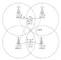
도 8은 단일 네트워크에서 사용되는 다중 CoMP 방식의 일 예를 도시한 도면이다.8 illustrates an example of a multiple CoMP scheme used in a single network.
도 8을 참조하면, 한 쌍의 기지국(기지국 A 및 기지국 B)은 조인트 프로세싱(CoMP-JP)을 이용하여 단말 1을 서빙할 수 있고, 다른 쌍의 기지국(기지국 C 및 기지국 D)은 조인트 프로세싱(CoMP-JP)을 이용하여 단말 2를 서빙할 수 있다. 동시에, 단말 2를 서빙하는 기지국은 CoMP 빔포밍 방식을 이용하여 단말 1을 서빙할 수 있고, 단말 1을 서빙하는 기지국은 CoMP-빔포밍 방식을 이용하여 단말 2를 서빙할 수 있다.Referring to FIG. 8, a pair of base stations (base station A and base station B) may serve terminal 1 using joint processing (CoMP-JP), and another pair of base stations (base station C and base station D) may perform joint processing.
본 발명에서는 다중 CoMP 방식이 허용된다고 가정하고, 각 단말의 최소 요구 데이터 전송률을 충족시키기 위한 다수의 선택 단계로 구성된 적응적 CoMP 방식 선택 방법을 제공할 것이다.In the present invention, it is assumed that multiple CoMP schemes are allowed, and an adaptive CoMP scheme selection method comprising a plurality of selection steps for satisfying a minimum required data rate of each terminal will be provided.
단말에 의해 사용될 CoMP 방식을 선택하는 경우, 타겟 단말에 대한 최소 요구 데이터 전송률을 고려하는 것이 바람직하다. 단말의 데이터 전송률은 하향링크(혹은 순방향 링크)의 채널 상태 및 네트워크에 의해 선택된 CoMP 방식 등과 같은 요인들에 의존적일 수 있다.When selecting a CoMP scheme to be used by the terminal, it is preferable to consider the minimum required data rate for the target terminal. The data rate of the UE may depend on factors such as a downlink (or forward link) channel state and a CoMP scheme selected by the network.
예를 들어, 단말이 셀의 중심 지역보다 더 열악한 하향링크 채널 상태인 셀 경계 지역으로 향하여 이동하는 경우, 9.6Kbps의 최소 요구 데이터 전송률을 충족 시키기 위한 하나의 방법은 CoMP 방식을 이용하는 것이다. 일 예로서, CoMP 방식 중 협력 스케줄링/빔포밍(CoMP-CS/CB) 방식이 선택되었다고 가정한다. 단말이 셀 경계 지역으로 더 이동하면, 하향링크 채널 상태가 더 악화되어 협력 스케줄링/빔포밍(CoMP-CS/CB)을 사용하여도 최소 요구 데이터 전송률이 충족될 수 없다.For example, when the terminal moves toward the cell boundary region which is inferior to the lower channel state than the center region of the cell, one method for satisfying the minimum required data rate of 9.6 Kbps is to use the CoMP scheme. As an example, it is assumed that a cooperative scheduling / beamforming (CoMP-CS / CB) scheme is selected among the CoMP schemes. If the UE moves further to the cell boundary region, the downlink channel state is further deteriorated, so that the minimum required data rate cannot be satisfied even when using cooperative scheduling / beamforming (CoMP-CS / CB).
이를 해결하기 위한 하나의 방법은 협력 스케줄링/빔포밍을 수행하는 CoMP 협력 포인트 집합인 CCPS 내의 몇 개의 기지국을 사일런싱하는 것이다. 이웃 기지국을 사일런싱하여 그 셀로부터의 간섭을 더 줄임으로써 단말의 데이터 전송률 및 수신신호 대 간섭 및 잡음비를 효과적으로 증가시킬 수 있다.One way to solve this problem is to silence several base stations in CCPS, a CoMP cooperative point set that performs cooperative scheduling / beamforming. By silencing the neighboring base station to further reduce the interference from the cell, it is possible to effectively increase the data rate and the received signal-to-interference and noise ratio of the terminal.
네트워크가 다중 CoMP 방식을 지원할 수 있다고 가정한다. 이때, 네트워크가 지원하는 CoMP 방식이 우선 정의될 필요가 있다. 예를 들어, 네트워크가 협력 빔포밍(Coordinate-Beamforming), 협력 사일런싱(Coordinate-Silencing) 및 조인트 프로세싱(CoMP-JP)과 같은 CoMP 방식을 지원할 수 있는 경우, 나중에 오는 CoMP 방식이 타겟 단말에서 간섭이 더 적고 더 높은 수신신호 대 간섭 및 잡음비를 산출하도록 다음과 같이 CoMP 방식의 순서를 정의할 수 있다.Assume that a network can support multiple CoMP schemes. At this time, the CoMP scheme supported by the network needs to be defined first. For example, if the network can support CoMP schemes such as Coordinate-Beamforming, Coordinate-Silencing, and Joint Processing (CoMP-JP), the later CoMP scheme interferes at the target terminal. To calculate this smaller and higher received signal to interference and noise ratio, the order of the CoMP scheme can be defined as follows.
CoMP 방식의 순서={협력 빔포밍, 협력 사일런싱, 조인트 프로세싱(JP)}Order of CoMP method = {cooperative beamforming, cooperative silencing, joint processing}
이하에서 이러한 CoMP 방식의 순서에 기초하여 단말의 적응적 CoMP 방식의 선택 방법에 대해 기술한다.Hereinafter, a method of selecting an adaptive CoMP scheme of the UE will be described based on the order of the CoMP scheme.
단말이 최소 요구 데이터 전송률을 충족시키지 못하는 경우에, 단말은 미리 정의된 CoMP 방식의 순서에서 제 1 CoMP 방식을 선택할 수 있다. 이 경우에는 제 1 CoMP 방식이 협력 빔포밍 방식이 될 것이다. 단말이 협력 빔포밍 방식을 수행하고 있는 동안, 수신신호 대 간섭 및 잡음비가 더 작아지면, 다시 단말의 최소 요구 데이터 전송률을 충족시키지 못할 수 있다. 그러면, 단말은 미리 정의된 순서에서 다음의 CoMP 방식을 선택하여 이용할 수 있다. 다음의 CoMP 방식은 협력 사일런싱 방식이 될 것이다. 사일런싱될 셀을 선택하는데 있어서, 타겟 단말로 상당히 큰 간섭을 야기할 수 있고 단말의 수신신호 대 간섭 및 잡음비를 증대시키는 셀을 선택하는 것이 바람직하다.If the terminal does not meet the minimum required data rate, the terminal may select the first CoMP scheme in the order of the predefined CoMP scheme. In this case, the first CoMP scheme will be a cooperative beamforming scheme. While the terminal is performing the cooperative beamforming scheme, if the received signal-to-interference and noise ratio becomes smaller, it may not again meet the minimum required data rate of the terminal. Then, the UE can select and use the following CoMP scheme in a predefined order. The next CoMP approach will be cooperative silencing. In selecting a cell to be silenced, it is desirable to select a cell that can cause significant interference to the target terminal and increase the received signal to interference and noise ratio of the terminal.
단말이 협력 빔포밍 방식 및 협력 사일런싱 방식으로 동작하는 동안, 수신신호 대 간섭 및 잡음비가 더 작아지면, 단말은 다시 최소 요구 데이터 전송률을 충족시키지 못할 수 있다. 그러면, 단말은 미리 정의된 순서에 따라 다음 CoMP 방식을 이용하는 선택을 할 수 있다. 이 경우는 단말이 조인트 프로세싱 방식을 선택하는 것이다.While the terminal operates in the cooperative beamforming scheme and the cooperative silencing scheme, if the received signal-to-interference and noise ratio becomes smaller, the terminal may again fail to meet the minimum required data rate. Then, the terminal may select using the next CoMP method in a predefined order. In this case, the terminal selects a joint processing scheme.
조인트 프로세싱 방식이 수행되어야 바람직한 셀 들을 선택하는데 있어서, 타겟 단말의 수신신호 대 간섭 및 잡음비를 최대화할 수 있는 셀을 선택하는 것이 바람직하다. 단말이 조인트 프로세싱을 이용하여 최소 요구 데이터 전송률을 충족시킬 수 없다면, 링크를 드롭(drop)하는 것이 바람직하다.In selecting the desired cells when the joint processing scheme should be performed, it is preferable to select a cell that can maximize the received signal-to-interference and noise ratio of the target terminal. If the terminal cannot meet the minimum required data rate using joint processing, it is desirable to drop the link.
도 9는 단말이 CoMP 방식을 선택하는 바람직한 수행 과정의 일 예를 도시한 도면이다.9 is a diagram illustrating an example of a preferred process of the UE selecting the CoMP scheme.
도 9를 참조하면, 먼저 단말이 선택할 CoMP 방식의 순서는 사전에 정의된 규칙에 따라 설정될 수 있다(S905). 현재 단말의 데이터 전송률이 최소 요구 데이터 전송률 보다 작으면(S910), 단말은 미리 정의된 CoMP 방식의 순서에 따라 제 1 CoMP 방식을 선택하고(S915), 그렇지 않으면, 소정 시간(T1) 동안 계속 동작을 수행한다(S920).Referring to FIG. 9, first, the order of the CoMP scheme to be selected by the UE may be set according to a predefined rule (S905). If the data rate of the current terminal is less than the minimum required data rate (S910), the terminal selects the first CoMP scheme according to the order of the predefined CoMP scheme (S915), otherwise, the operation continues for a predetermined time (T1). To perform (S920).
그 후, 단말은 수신신호 대 간섭 및 잡음비를 극대화할 수 있는 셀 들을 선택할 수 있다(S925). 그리고, 소정 시간(T1) 동안 선택한 CoMP 방식으로 동작을 수행할 수 있다(S930). 그 후, 단말의 데이터 전송률을 최소 요구 데이터 전송률과 비교하여, 단말의 데이터 전송률이 최소 요구 데이터 전송률보다 크면, 계속 일정 시간 동안 선택한 제 1 CoMP 방식으로 동작을 수행한다. 이와 달리, 단말의 현재 데이터 전송률이 최소 요구 데이터 전송률보다 작으면(S935), 단말은 다음의 제 2 CoMP 방식을 선택할 수 있다(S940).Thereafter, the terminal can select cells that can maximize the received signal-to-interference and noise ratio (S925). In operation S930, an operation may be performed using a selected CoMP scheme for a predetermined time T1. Thereafter, the data rate of the terminal is compared with the minimum required data rate, and if the data rate of the terminal is larger than the minimum required data rate, the operation is continuously performed for a predetermined time. In contrast, if the current data rate of the terminal is less than the minimum required data rate (S935), the terminal may select the next second CoMP scheme (S940).
제 2 CoMP 방식이 최종 CoMP 방식이 아니라면(S945), 단말은 수신신호 대 간섭 및 잡음비를 극대화할 수 있는 셀 들을 선택할 수 있다(S950). 그리고, 단말은 소정 시간(T2) 동안 계속 제 2 CoMP 방식 동작을 수행할 수 있다(S955). 이와 달리, 제 2 CoMP 방식이 최종 CoMP 방식이라면, 단말은 제 2 CoMP 방식 동작을 중지하고 링크를 드롭할 수 있다(S960). 이때, 상기 단말이 드롭하는 링크는 하향링크(순방향 링크라고도 칭할 수 있다)일 수 있다.If the second CoMP scheme is not the final CoMP scheme (S945), the UE may select cells capable of maximizing the received signal-to-interference and noise ratio (S950). In operation S955, the terminal may continuously perform the second CoMP scheme operation for a predetermined time T2. In contrast, if the second CoMP scheme is the final CoMP scheme, the UE may stop the operation of the second CoMP scheme and drop the link (S960). In this case, the link dropped by the terminal may be downlink (also referred to as a forward link).
사일런싱 셀(CSPS)을 선택하는 과정에서, 특정 셀이 너무 많이 사일런싱되게 선택되는 경우에는, 그 셀의 처리량(throughput)은 네트워크에서 다른 셀과 비교할 때 상당히 작아질 수 있다. 이는 셀 들 간의 총 셀 처리량의 관점에서, 불공평할 수 있고, 따라서 각 단말의 처리량도 불공평해 질 수 있다. In the process of selecting a silencing cell (CSPS), if a particular cell is selected to be silenced too much, the throughput of that cell can be quite small compared to other cells in the network. This may be unfair in view of the total cell throughput between cells, and thus the throughput of each terminal may also be unfair.
이러한 문제를 해결하기 위한 하나의 방법은 단말이 사일런싱할 셀을 번갈아 공평하게 선택할 수 있는 라운드 로빈(round robin) 방식으로 선택할 수 있다. 즉, CoMP 협력 포인트 집합(CCPS)에서의 셀 들을 하나씩 차례로 선택하는 것이다. 또한, 선택은 특정 시간에 임의의 셀 수를 선택하는 것으로 이루어질 수 있다.One method for solving such a problem may be selected in a round robin manner in which the terminal may alternately select cells to be silenced. That is, cells in the CoMP cooperation point set (CCPS) are selected one by one. In addition, the selection may consist in selecting any number of cells at a particular time.
또 다른 해결 방법으로서, 셀의 총 처리량을 체크하여 최고의 총 처리량을 갖는 셀을 사일런싱하는 방법이다. 이 방법을 사용하여, 셀 범위 내의 단말로 가장 큰 데이터량을 전송한 셀은 먼저 사일런싱 되는 것이다. 셀이 사일런싱되는 경우, 선택 지시자(indicator)는 1씩 증가하여 사일런싱을 위해 이 셀이 선택되었음을 지시할 수 있다. 따라서, 다음 선택 시에, 최고의 선택 지시자 값을 갖는 셀은 사일런싱될 셀 선택으로부터 제외될 수 있다.Another solution is to check the total throughput of the cells to silence the cell with the highest total throughput. Using this method, the cell that has transmitted the largest amount of data to the terminal within the cell range is first silenced. When a cell is silenced, the selection indicator may increase by 1 to indicate that the cell is selected for silencing. Thus, at the next selection, the cell with the highest selection indicator value may be excluded from the cell selection to be silenced.
이하에서는 네트워크 엔티티가 CoMP 방식을 선택하는데 필요한 정보를 획득하는 방법에 대해 설명한다.Hereinafter, a method of obtaining information required for the network entity to select a CoMP scheme will be described.
네트워크 엔티티는 각 단말이 각기 주어진 최소 요구 데이터 전송률을 만족시키고 있는지의 여부를 과거 단말로 전송된 데이터 정보를 이용하여 직접 판단할 수도 있으며, 단말로부터 추가적인 정보를 획득하여 이를 수행할 수도 있다.The network entity may directly determine whether each terminal satisfies a given minimum required data rate by using data information transmitted to the past terminal, or may obtain additional information from the terminal and perform this.
도 10은 네트워크 엔티티가 CoMP 방식을 선택하는데 필요한 정보를 획득하는 바람직한 수행 과정을 나타낸 도면이다.FIG. 10 is a diagram illustrating a preferred process of acquiring information required for a network entity to select a CoMP scheme.
도 10을 참조하면, 단말은 현재 단말 자신의 최소 요구 데이터 전송률을 충족하지 못하였음을 나타내는 메시지 또는 도움 지시자(help indicator)를 서빙 기지국으로 전송할 수 있다(S1010). 이때, 도움 지시자는 간단히 1비트로 지시할 수 있거나 혹은 CoMP 방식 선택을 위해 요구되는 채널 상태 정보를 포함하여 지시할 수 있다. 네트워크 엔티티는 서빙 기지국으로부터 단말이 보고한 보고 메시지를 수신할 수 있다(S1020).Referring to FIG. 10, the terminal may transmit a message or a help indicator indicating that the terminal does not meet the minimum required data transmission rate to the serving base station (S1010). In this case, the help indicator may simply indicate 1 bit or may include channel state information required for selecting a CoMP scheme. The network entity may receive a report message reported by the terminal from the serving base station (S1020).
상기 보고 메시지에 서빙 기지국은 이벤트 트리거링(event-triggering)되어 단말로 채널 상태 정보(CSI: Channel State Information) 피드백을 요구하는 채널 상태 정보 요구 지시자(CSI-RI: Channel State Information-Request Indicator)를 전송할 수 있다(S1030). 이때, 서빙 기지국은 단일 기지국 또는 다중 기지국일 수 있다.The serving base station is event-triggered in the report message and transmits a channel state information request indicator (CSI-RI) requesting channel state information (CSI) feedback to the terminal. It may be (S1030). In this case, the serving base station may be a single base station or multiple base stations.
그 후, 단말은 채널 상태 정보 요구 지시자를 수신하는 즉시 비주기적 제어 채널(aperiodic control channel)을 통하여 서빙 기지국으로 채널 상태 정보를 전송할 수 있다(S1040). 이때 단말이 채널 상태 정보를 주기적으로 서빙 기지국으로 전송하는 경우, 많은 채널 상태 정보량에 따른 자원 할당에 의해 자원 낭비가 될 수 있으므로, 비주기적으로 전송하는 것이 바람직하다.Thereafter, upon receiving the channel state information request indicator, the terminal may transmit the channel state information to the serving base station through an aperiodic control channel (S1040). In this case, when the terminal periodically transmits the channel state information to the serving base station, it may be a waste of resources by resource allocation according to a large amount of channel state information, it is preferable to transmit aperiodically.
이때, 단말이 서빙 기지국으로 전송하는 CSI에는 측정된 각 기지국 별 및 각 CoMP 집합의 수신신호 대 간섭 및 잡음 비(SINR), 채널 상태 정보를 포함할 수 있다. 수신신호 대 간섭 및 잡음 비는 데이터 전송률과 1:1로 매칭되는 관계이며, 수신신호 대 간섭 및 잡음 비는 데이터 전송률 크기 정도를 나타낼 수 있는 척도가 될 수 있다. 서빙 기지국은 단말로부터 수신한 상기 CSI를 네트워크 엔티티로 전송할 수 있다(S1050).In this case, the CSI transmitted by the terminal to the serving base station may include the received signal-to-interference and noise ratio (SINR) and channel state information of each base station and each CoMP set measured. The received signal-to-interference and noise ratio is a 1: 1 match with the data rate, and the received signal-to-interference and noise ratio may be a measure of the magnitude of the data rate. The serving base station may transmit the CSI received from the terminal to a network entity (S1050).
그 후, 네트워크 엔티티는 현재 상황에 적합한 CoMP 방식을 적응적으로 선택할 수 있다.The network entity can then adaptively choose the CoMP scheme that is appropriate for the current situation.
이상에서 살펴본 바와 같이, 본 발명에서는 서로 다른 3개의 CoMP을 가정한 실시예를 기술하였지만, 기술되지 않은 또 다른 CoMP 방식을 포함하여 CoMP 방식을 선택하는 방법에 있어서도 확장되어 적용될 수 있음은 자명하다.As described above, in the present invention, an embodiment in which three different CoMPs are assumed has been described, but it is obvious that the present invention may be extended to a method of selecting a CoMP method including another CoMP method not described.
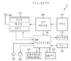
도 11은 단말 또는 접속 단말의 구조의 일 예를 나타낸 블록도이다.11 is a block diagram illustrating an example of a structure of a terminal or an access terminal.
도 11을 참조하면, 단말은 프로세서(또는 디지털 신호 프로세서)(110), RF 모듈(135), 전력 관리 모듈(105), 안테나(140), 배터리(155), 디스플레이(115), 키패드(120), 메모리(130), SIM(Subscriber Identification Module) 카드(125)(옵션일 수 있음), 스피커(145) 및 마이크로폰(150)을 포함한다.Referring to FIG. 11, the terminal includes a processor (or a digital signal processor) 110, an
사용자는, 예를 들어 키패드(120) 버튼을 누르거나 마이크로폰(150)을 이용한 음석 활성화에 의해, 전화번호와 같은 지시 정보를 입력한다. 마이크로프로세서(110)는 지시 정보를 수신 및 처리하여 전화 번호 다이얼링과 같은 적합한 기능을 수행한다. 동작 데이터를 SIM(Subscriber Identity Module) 카드(125) 또는 메모리 모듈(130)에서 얻어 상기 기능을 수행할 수 있다. 또한, 상기 프로세서(110)는 사용자의 참조 및 편의를 위해 지시 및 동작 정보를 디스플레이(115)에 표시할 수 있다.The user inputs indication information such as a telephone number, for example, by pressing a button of the
상기 프로세서(110)는 지시 정보를 RF 모듈(135)에 전달하여, 예를 들어 음성 통신 데이터를 포함하는 무선 신호를 전송하는 것과 같이 통신을 개시할 수 있다. RF 모듈(135)은 무선 신호의 수신 및 송신을 위한 수신기 및 송신기를 포함한다. 안테나(140)는 무선 신호의 전송 및 수신을 용이하게 한다. 무선 신호를 수신하면, RF 모듈(135)은 프로세서(110)를 위해 상기 신호를 전달 및 기저 대역으로 변환할 수 있다.The
상기 처리된 신호는 예를 들어 스피커(145)를 통해 가청되거나 판독 가능한 정보로 전환된다. 프로세서(110)는 본 명세서에서 설명한 다양한 과정을 수행하는데 필요한 프로토콜 및 기능을 포함한다.The processed signal is converted into audible or readable information through, for example, a
이상에서 설명된 실시예들은 본 발명의 구성요소들과 특징들이 소정 형태로 결합된 것들이다. 각 구성요소 또는 특징은 별도의 명시적 언급이 없는 한 선택적인 것으로 고려되어야 한다. 각 구성요소 또는 특징은 다른 구성요소나 특징과 결합되지 않은 형태로 실시될 수 있다. 또한, 일부 구성요소들 및/또는 특징들을 결합하여 본 발명의 실시예를 구성하는 것도 가능하다. 본 발명의 실시예들에서 설명되는 동작들의 순서는 변경될 수 있다. 어느 실시예의 일부 구성이나 특징은 다른 실시예에 포함될 수 있고, 또는 다른 실시예의 대응하는 구성 또는 특징과 교체될 수 있다. 특허청구범위에서 명시적인 인용 관계가 있지 않은 청구항들을 결합하여 실시예를 구성하거나 출원 후의 보정에 의해 새로운 청구항으로 포함시킬 수 있음은 자명하다.The embodiments described above are the components and features of the present invention are combined in a predetermined form. Each component or feature is to be considered optional unless stated otherwise. Each component or feature may be implemented in a form that is not combined with other components or features. It is also possible to combine some of the components and / or features to form an embodiment of the invention. The order of the operations described in the embodiments of the present invention may be changed. Some configurations or features of certain embodiments may be included in other embodiments, or may be replaced with corresponding configurations or features of other embodiments. It is obvious that the claims may be combined to form an embodiment by combining claims that do not have an explicit citation relationship in the claims or as new claims by post-application correction.
본 발명에 따른 실시예는 다양한 수단, 예를 들어, 하드웨어, 펌웨어(firmware), 소프트웨어 또는 그것들의 결합 등에 의해 구현될 수 있다. 하드웨어에 의한 구현의 경우, 본 발명의 일 실시예는 하나 또는 그 이상의 ASICs(Application Specific Integrated Circuits), DSPs(Digital Signal Processors), DSPDs(Digital Signal Processing Devices), PLDs(Programmable Logic Devices), FPGAs(Field Programmable Gate Arrays), 프로세서, 콘트롤러, 마 이크로 콘트롤러, 마이크로 프로세서 등에 의해 구현될 수 있다.Embodiments according to the present invention may be implemented by various means, for example, hardware, firmware, software, or a combination thereof. In the case of a hardware implementation, an embodiment of the present invention may include one or more Application Specific Integrated Circuits (ASICs), Digital Signal Processors (DSPs), Digital Signal Processing Devices (DSPDs), Programmable Logic Devices (PLDs), FPGAs ( Field Programmable Gate Arrays), processors, controllers, microcontrollers, microprocessors, and the like.
펌웨어나 소프트웨어에 의한 구현의 경우, 본 발명의 일 실시예는 이상에서 설명된 기능 또는 동작들을 수행하는 모듈, 절차, 함수 등의 형태로 구현될 수 있다. 소프트웨어 코드는 메모리 유닛에 저장되어 프로세서에 의해 구동될 수 있다. 상기 메모리 유닛은 상기 프로세서 내부 또는 외부에 위치하여, 이미 공지된 다양한 수단에 의해 상기 프로세서와 데이터를 주고 받을 수 있다.In the case of implementation by firmware or software, an embodiment of the present invention may be implemented in the form of a module, procedure, function, etc. that performs the functions or operations described above. The software code may be stored in a memory unit and driven by a processor. The memory unit may be located inside or outside the processor, and may exchange data with the processor by various known means.
본 발명은 본 발명의 정신 및 필수적 특징을 벗어나지 않는 범위에서 다른 특정한 형태로 구체화될 수 있음은 당업자에게 자명하다. 따라서, 상기의 상세한 설명은 모든 면에서 제한적으로 해석되어서는 아니 되고 예시적인 것으로 고려되어야 한다. 본 발명의 범위는 첨부된 청구항의 합리적 해석에 의해 결정되어야 하고, 본 발명의 등가적 범위 내에서의 모든 변경은 본 발명의 범위에 포함된다.It will be apparent to those skilled in the art that the present invention may be embodied in other specific forms without departing from the spirit or essential characteristics thereof. Accordingly, the above detailed description should not be interpreted as limiting in all aspects and should be considered as illustrative. The scope of the invention should be determined by reasonable interpretation of the appended claims, and all changes within the equivalent scope of the invention are included in the scope of the invention.
본 발명에 관한 이해를 돕기 위해 상세한 설명의 일부로 포함되는, 첨부 도면은 본 발명에 대한 실시예를 제공하고, 상세한 설명과 함께 본 발명의 기술적 사상을 설명한다.BRIEF DESCRIPTION OF THE DRAWINGS The accompanying drawings, which are included as part of the detailed description in order to provide a thorough understanding of the present invention, provide an embodiment of the present invention and together with the description, illustrate the technical idea of the present invention.
도 1은 기지국을 제어하는 시스템이 클러스터를 구성하는 것을 나타낸 도면,1 is a diagram showing a system for controlling a base station configures a cluster;
도 2는 단말이 클러스터를 구성하는 것을 나타낸 도면,2 is a diagram illustrating a terminal configuring a cluster;
도 3은 단말 1이 기지국 1, 기지국 2 및 기지국 3 간의 핸드오프 하는 상황을 나타낸 도면,3 is a diagram illustrating a situation in which
도 4는 CoMP 집합 분류의 일 예를 나타낸 도면,4 is a diagram illustrating an example of classification of a CoMP set;
도 5는 CoMP 집합 분류의 일 예를 나타낸 도면,5 is a diagram illustrating an example of CoMP set classification,
도 6은 단말 1이 기지국 1, 기지국 2 및 기지국 3 간의 CoMP 집합 단위로 핸드오프 하는 상황을 나타낸 도면,6 is a diagram illustrating a situation in which
도 7은 CoMP 집합 분류의 일 예를 나타낸 도면,7 is a diagram illustrating an example of CoMP set classification,
도 8은 단일 네트워크에서 사용되는 다중 CoMP 방식의 일 예를 도시한 도면,8 illustrates an example of a multiple CoMP scheme used in a single network.
도 9는 단말이 CoMP 방식을 선택하는 바람직한 수행 과정의 일 예를 도시한 도면, 그리고,9 is a diagram illustrating an example of a preferred execution process for a UE to select a CoMP scheme, and
도 10은 네트워크 엔티티가 CoMP 방식을 선택하는데 필요한 정보를 획득하는 바람직한 수행 과정을 나타낸 도면, 그리고,FIG. 10 is a diagram illustrating a preferred process of acquiring information required for a network entity to select a CoMP scheme, and FIG.
도 11은 단말 또는 접속 단말의 구조의 일 예를 나타낸 블록도이다.11 is a block diagram illustrating an example of a structure of a terminal or an access terminal.
Claims (12)
Translated fromKoreanPriority Applications (2)
| Application Number | Priority Date | Filing Date | Title |
|---|---|---|---|
| US13/147,049US9137726B2 (en) | 2009-01-30 | 2010-01-28 | Method for selecting an adaptive CoMP scheme |
| PCT/KR2010/000505WO2010087619A2 (en) | 2009-01-30 | 2010-01-28 | Method for selecting an adaptive comp scheme |
Applications Claiming Priority (10)
| Application Number | Priority Date | Filing Date | Title |
|---|---|---|---|
| US14839709P | 2009-01-30 | 2009-01-30 | |
| US61/148,397 | 2009-01-30 | ||
| US15908109P | 2009-03-10 | 2009-03-10 | |
| US61/159,081 | 2009-03-10 | ||
| US16303009P | 2009-03-24 | 2009-03-24 | |
| US61/163,030 | 2009-03-24 | ||
| US16552009P | 2009-04-01 | 2009-04-01 | |
| US61/165,520 | 2009-04-01 | ||
| US16590609P | 2009-04-02 | 2009-04-02 | |
| US61/165,906 | 2009-04-02 |
Publications (2)
| Publication Number | Publication Date |
|---|---|
| KR20100088512Atrue KR20100088512A (en) | 2010-08-09 |
| KR101572891B1 KR101572891B1 (en) | 2015-11-30 |
Family
ID=42754721
Family Applications (2)
| Application Number | Title | Priority Date | Filing Date |
|---|---|---|---|
| KR1020090045447AExpired - Fee RelatedKR101572891B1 (en) | 2009-01-30 | 2009-05-25 | Method of adaptive selecting of CoMP scheme |
| KR1020090045446AExpired - Fee RelatedKR101571729B1 (en) | 2009-01-30 | 2009-05-25 | How to Perform a CoMP Set Unit Handoff |
Family Applications After (1)
| Application Number | Title | Priority Date | Filing Date |
|---|---|---|---|
| KR1020090045446AExpired - Fee RelatedKR101571729B1 (en) | 2009-01-30 | 2009-05-25 | How to Perform a CoMP Set Unit Handoff |
Country Status (3)
| Country | Link |
|---|---|
| US (2) | US8265629B2 (en) |
| KR (2) | KR101572891B1 (en) |
| WO (2) | WO2010087618A2 (en) |
Cited By (4)
| Publication number | Priority date | Publication date | Assignee | Title |
|---|---|---|---|---|
| WO2015190784A1 (en)* | 2014-06-08 | 2015-12-17 | 엘지전자 주식회사 | Method and apparatus for establishing group cell on basis of measurement signal variation |
| US9419696B2 (en) | 2011-12-19 | 2016-08-16 | Comcast Cable Communications, Llc | Beam information exchange between base stations |
| US10085165B2 (en) | 2011-09-23 | 2018-09-25 | Comcast Cable Communications, Llc | Multi-cell signals in OFDM wireless networks |
| US12445912B2 (en) | 2022-05-11 | 2025-10-14 | Comcast Cable Communications, Llc | Beamforming in wireless communications |
Families Citing this family (81)
| Publication number | Priority date | Publication date | Assignee | Title |
|---|---|---|---|---|
| EP2387269B1 (en)* | 2009-02-02 | 2019-04-10 | Huawei Technologies Co., Ltd. | Method, device and system for multi-carrier cell handover |
| US8908595B2 (en)* | 2009-03-12 | 2014-12-09 | Qualcomm Incorporated | Methods and apparatus for adjacent channel interference mitigation in access point base stations |
| US8660071B2 (en)* | 2009-03-19 | 2014-02-25 | Qualcomm Incorporated | Adaptive resource partitioning in a wireless communication network |
| CN101867938B (en)* | 2009-04-20 | 2013-01-02 | 电信科学技术研究院 | Method and device for configuring uplink reference signal of multipoint cooperative transmission |
| EP2246992B1 (en)* | 2009-04-27 | 2015-03-18 | Alcatel Lucent | A method for uplink transmission of data from a user terminal, a base station, a coordination device, and a communication network therefor |
| KR101618283B1 (en)* | 2009-05-22 | 2016-05-04 | 삼성전자주식회사 | Method of information feedback for coordinated multiple point communications |
| US8681682B2 (en)* | 2009-05-22 | 2014-03-25 | Lg Electronics Inc. | Method and apparatus for cooperative multiple point transmission and reception |
| US9184511B2 (en) | 2009-07-10 | 2015-11-10 | Futurewei Technologies, Inc. | System and method for downlink channel sounding in wireless communications systems |
| US8588801B2 (en)* | 2009-08-21 | 2013-11-19 | Qualcomm Incorporated | Multi-point equalization framework for coordinated multi-point transmission |
| KR20110037420A (en)* | 2009-10-06 | 2011-04-13 | 주식회사 팬택 | Method for uplink multiple reception and base station apparatus using same |
| JP5081257B2 (en)* | 2010-02-04 | 2012-11-28 | 株式会社エヌ・ティ・ティ・ドコモ | Radio communication system, radio base station apparatus, and communication control method |
| US8934557B2 (en)* | 2010-06-30 | 2015-01-13 | Telefonaktiebolaget L M Ericsson (Publ) | Statistical joint precoding in multi-cell, multi-user MIMO |
| EP2605591A4 (en)* | 2010-08-12 | 2016-08-24 | Fujitsu Ltd | COMMUNICATION ESTABLISHING METHOD, RADIO BASE STATION AND MOBILE STATION |
| KR101715866B1 (en) | 2010-08-26 | 2017-03-13 | 삼성전자주식회사 | Method and apparatus for adaptive scheduling based on coordinated rank in multi-cell communication system |
| EP2642674B1 (en)* | 2010-11-17 | 2020-04-08 | LG Electronics Inc. | Method and device for aperiodically reporting channel state information in wireless connection system |
| US10341919B2 (en)* | 2010-11-24 | 2019-07-02 | Elta Systems Ltd. | Handover initiation methods and systems for improvement of cellular network performance |
| CN102595513B (en)* | 2011-01-06 | 2015-09-16 | 中兴通讯股份有限公司 | A kind of based on retransmitting the method and system triggering coordinated multipoint transmission |
| CN102594420B (en)* | 2011-01-10 | 2015-08-05 | 上海贝尔股份有限公司 | Disturbance restraining method in multipoint coordinated transmission system and device |
| US9137702B2 (en)* | 2011-01-17 | 2015-09-15 | Telefonaktiebolaget L M Ericsson (Publ) | Methods and devices for multipoint transmission |
| JP5791638B2 (en)* | 2011-01-31 | 2015-10-07 | パナソニック インテレクチュアル プロパティ コーポレーション オブアメリカPanasonic Intellectual Property Corporation of America | Terminal and quality transmission method |
| EP2498530A1 (en)* | 2011-03-10 | 2012-09-12 | NTT DoCoMo, Inc. | Method for coordinated multipoint (CoMP) transmission/reception in wireless communication networks with reconfiguration capability |
| CN102802219A (en)* | 2011-05-27 | 2012-11-28 | 中兴通讯股份有限公司 | Coordinated-multiple-point (Comp)-based service switching method and system |
| EP2704507A2 (en)* | 2011-05-30 | 2014-03-05 | Huawei Technologies Co., Ltd. | Coordinated multi-point transmission/reception method, device and system |
| US8457642B2 (en) | 2011-06-08 | 2013-06-04 | Telefonaktiebolaget L M Ericsson (Publ) | Determining a coordinating set of cells for multipoint reception of uplink transmission from a mobile terminal |
| CN107196728B (en) | 2011-06-28 | 2019-07-09 | 索尼公司 | Communication means, communication device, terminal |
| KR101896001B1 (en)* | 2011-07-12 | 2018-09-06 | 한국전자통신연구원 | Method of mobility management for mobile terminal in a heterogeneous network environment |
| US9178576B2 (en)* | 2011-07-19 | 2015-11-03 | Lg Electronics Inc. | Communication method using multiple transmission points, and apparatus for same |
| KR101810688B1 (en)* | 2011-08-03 | 2018-01-25 | 아주대학교산학협력단 | Terminal controlling cooperative transmission, and cooperative transmission control method thereof, in a communication system |
| EP2750435B1 (en)* | 2011-10-03 | 2017-09-06 | Ntt Docomo, Inc. | Wireless communications system, feedback method, user terminal, and wireless base station device |
| WO2013069856A1 (en)* | 2011-11-11 | 2013-05-16 | 주식회사 케이티 | Digital signal processing device, signal processing system, and signal processing method |
| US9270346B2 (en)* | 2011-12-02 | 2016-02-23 | Apple Inc. | Methods for operating wireless electronic devices in coordinated multipoint transmission networks |
| US9743343B2 (en)* | 2011-12-12 | 2017-08-22 | Intel Deutschland Gmbh | Method for receiving information and communication terminal |
| US9276810B2 (en)* | 2011-12-16 | 2016-03-01 | Futurewei Technologies, Inc. | System and method of radio bearer management for multiple point transmission |
| US9485737B2 (en) | 2011-12-26 | 2016-11-01 | Kt Corporation | Controlling radio units to transmitting signal with different transmission power |
| US9357505B2 (en) | 2011-12-26 | 2016-05-31 | Kt Corporation | Processing digital signal |
| CN103200629B (en)* | 2012-01-10 | 2016-08-03 | 华为技术有限公司 | Base station switch method, X2 interface method for building up, base station, user terminal and system |
| US8953478B2 (en)* | 2012-01-27 | 2015-02-10 | Intel Corporation | Evolved node B and method for coherent coordinated multipoint transmission with per CSI-RS feedback |
| CN108112035A (en) | 2012-01-27 | 2018-06-01 | 三菱电机株式会社 | Mobile communication system |
| EP3413474B1 (en)* | 2012-01-30 | 2024-07-17 | NEC Corporation | Wireless communication system and method for controlling reporting settings |
| US9344918B2 (en)* | 2012-02-14 | 2016-05-17 | Kyocera Corporation | Mobile communication system, base station, and communication control method |
| US9345014B2 (en)* | 2012-02-14 | 2016-05-17 | Kyocera Corporation | Mobile communication system, base station, user terminal, and communication control method |
| WO2013133596A1 (en)* | 2012-03-05 | 2013-09-12 | 엘지전자 주식회사 | Method and apparatus for carrying out measurement report in wireless communication system |
| US9590775B2 (en)* | 2012-03-29 | 2017-03-07 | Sony Corporation | Radio communication apparatus and radio communication method, and radio communication system |
| CN102647262B (en)* | 2012-04-09 | 2014-11-12 | 北京航空航天大学 | Orthogonal beam forming-based hidden feedback transmission method in cooperative communication system |
| US8838119B2 (en) | 2012-06-26 | 2014-09-16 | Futurewei Technologies, Inc. | Method and system for dynamic cell configuration |
| US20140092879A1 (en)* | 2012-10-02 | 2014-04-03 | Zte Wistron Telecom Ab | Downlink transmission point selection in a wireless heterogeneous network |
| US9628151B2 (en) | 2012-10-17 | 2017-04-18 | Telefonaktiebolaget Lm Ericsson (Publ) | Selection of access points for coordinated multipoint uplink reception |
| TWI474664B (en) | 2012-11-13 | 2015-02-21 | Ind Tech Res Inst | Method and apparatus for correcting wireless signal quality |
| KR101407103B1 (en)* | 2012-12-04 | 2014-06-13 | 서강대학교산학협력단 | Method of coordinated multi-point transmission and reception |
| EP2922333B1 (en)* | 2012-12-14 | 2017-02-01 | Huawei Technologies Co., Ltd | Methods and devices for selecting uplink comp set |
| US9516563B2 (en) | 2013-01-21 | 2016-12-06 | Intel Corporation | Apparatus, system and method of handover of a beamformed link |
| US10511504B2 (en)* | 2013-01-25 | 2019-12-17 | Qualcomm Incorporated | Cell-specific reference signal interference averaging |
| KR20140095912A (en) | 2013-01-25 | 2014-08-04 | 삼성전자주식회사 | APPARATUS AND METHOD FOR DETERMINING CLOUD CELL MEMBER BSs IN A CLOUD CELL COMMUNICATION SYSTEM |
| KR102018057B1 (en)* | 2013-02-25 | 2019-09-04 | 한국전자통신연구원 | Coodinated multi-point transmission and reception method in overlaid cell environment |
| KR102051831B1 (en)* | 2013-09-13 | 2019-12-04 | 삼성전자주식회사 | Method and apparatus for traffic load balancing in mobile communication system |
| KR102243276B1 (en)* | 2013-11-21 | 2021-04-22 | 한국전자통신연구원 | Method for aligning interference in wireless local area network |
| US10333737B2 (en)* | 2013-11-21 | 2019-06-25 | Electronics & Telecommunications Research Institute | Method of aligning interference in wireless local area network |
| KR102155523B1 (en) | 2014-01-20 | 2020-09-14 | 삼성전자 주식회사 | Method and apparatus for determining a conncetion configuration and performing a handover in wireless communication system supporting a dual connectivity |
| EP3114894B1 (en)* | 2014-03-07 | 2019-10-09 | Huawei Technologies Co., Ltd. | Soft transmit point and user equipment association method for radio access virtualization |
| US9877259B2 (en) | 2014-03-31 | 2018-01-23 | Huawei Technologies Co., Ltd. | Dynamic energy-efficient transmit point (TP) muting for virtual radio access network (V-RAN) |
| KR102201599B1 (en)* | 2014-07-01 | 2021-01-13 | 한국전자통신연구원 | method and apparatus for handover |
| JP6398612B2 (en)* | 2014-10-29 | 2018-10-03 | 富士通株式会社 | Base station and cell selection method |
| CN105791196B (en)* | 2014-12-25 | 2020-04-03 | 中兴通讯股份有限公司 | Splitting method and device for super cell |
| US10966194B2 (en) | 2015-04-15 | 2021-03-30 | Qualcomm Incorporated | Coordinated wireless communications using multiple transmission time intervals |
| US10440592B2 (en) | 2015-06-03 | 2019-10-08 | Telefonaktiebolaget Lm Ericsson (Publ) | Signaling of beam forming measurements |
| GB2539269A (en) | 2015-06-12 | 2016-12-14 | Nec Corp | Communication system |
| CN108029052B (en) | 2015-09-03 | 2021-03-19 | 瑞典爱立信有限公司 | Method and service access node for coordination of service access nodes in a service cluster |
| US10609616B2 (en) | 2015-12-22 | 2020-03-31 | Alfred Consulting LLC | System and method for using mobility information in heterogeneous networks |
| EP3188374B1 (en)* | 2015-12-28 | 2020-04-01 | Wipro Limited | Methods and systems for dynamic coordinated multi point link maintenance |
| EP3226616B1 (en) | 2016-03-29 | 2021-05-05 | Wipro Limited | Method and system for coordinated multipoint (comp) enabled handover in wireless communication networks |
| CN107425885B (en)* | 2017-08-02 | 2020-04-07 | 西安电子科技大学 | CoMP (coordinated Multi-point) down-mixing dynamic clustering method based on coalition game |
| CN109714772A (en)* | 2017-10-25 | 2019-05-03 | 索尼公司 | Electronic equipment and method for wireless communication |
| US11224081B2 (en) | 2018-12-05 | 2022-01-11 | Google Llc | Disengaged-mode active coordination set management |
| US12136967B2 (en) | 2018-12-28 | 2024-11-05 | Google Llc | User-equipment-coordination set for a wireless network |
| EP3884708A1 (en) | 2019-01-02 | 2021-09-29 | Google LLC | Multiple active-coordination-set aggregation for mobility management |
| WO2020159773A1 (en) | 2019-01-28 | 2020-08-06 | Google Llc | Dynamic carrier subband operation for active coordination sets |
| CA3127384C (en) | 2019-02-21 | 2023-12-12 | Google Llc | User-equipment-coordination set for a wireless network using an unlicensed frequency band |
| WO2020186097A1 (en) | 2019-03-12 | 2020-09-17 | Google Llc | User-equipment coordination set beam sweeping |
| US10893572B2 (en) | 2019-05-22 | 2021-01-12 | Google Llc | User-equipment-coordination set for disengaged mode |
| CN114365422B (en) | 2019-09-19 | 2025-01-24 | 谷歌有限责任公司 | Enhanced beam search for active coordination sets |
| US12408074B2 (en) | 2022-12-02 | 2025-09-02 | Electronics And Telecommunications Research Institute | Method and apparatus of data transmission for high capacity network |
Family Cites Families (14)
| Publication number | Priority date | Publication date | Assignee | Title |
|---|---|---|---|---|
| US6137789A (en)* | 1997-06-26 | 2000-10-24 | Nokia Mobile Phones Limited | Mobile station employing selective discontinuous transmission for high speed data services in CDMA multi-channel reverse link configuration |
| US6751199B1 (en)* | 2000-04-24 | 2004-06-15 | Qualcomm Incorporated | Method and apparatus for a rate control in a high data rate communication system |
| US7158504B2 (en)* | 2001-05-21 | 2007-01-02 | Lucent Technologies, Inc. | Multiple mode data communication system and method and forward and/or reverse link control channel structure |
| US7046648B2 (en)* | 2003-11-05 | 2006-05-16 | Interdigital Technology Corporation | Wireless communication method and apparatus for coordinating Node-B's and supporting enhanced uplink transmissions during handover |
| JP2006217011A (en)* | 2005-02-01 | 2006-08-17 | Fujitsu Ltd | Mobile station, base station, and wireless communication system |
| KR100735302B1 (en)* | 2006-02-08 | 2007-07-03 | 삼성전자주식회사 | How to select communication network in portable terminal |
| US8072946B2 (en)* | 2006-03-30 | 2011-12-06 | Intel Corporation | Coordinated transmissions in wireless networks |
| DK2103042T3 (en)* | 2007-01-11 | 2010-12-06 | Nds Ltd | Wireless networking system and approach |
| KR100996060B1 (en)* | 2007-04-04 | 2010-11-22 | 연세대학교 산학협력단 | Method and apparatus for transmitting and receiving data in communication system |
| US7826848B2 (en)* | 2007-10-31 | 2010-11-02 | Mitisubishi Electric Research Laboratories, Inc. | Cooperative communication in wireless cellular networks |
| KR100991792B1 (en)* | 2007-12-31 | 2010-11-04 | 엘지전자 주식회사 | Cooperative Multiple Input / Output Signal Transmitting and Receiving Method |
| EP2294883B1 (en)* | 2008-06-30 | 2016-08-17 | Telefonaktiebolaget LM Ericsson (publ) | Grouping user terminals into different coordination scheme groups |
| WO2010098974A2 (en)* | 2009-02-24 | 2010-09-02 | Elliott Hoole | Network cells that autonomously detect and measure ancillary communications for making handover decisions |
| US8254331B2 (en)* | 2009-03-31 | 2012-08-28 | Sprint Spectrum L.P. | Method and system for managing handoff in a radio access network |
- 2009
- 2009-05-25KRKR1020090045447Apatent/KR101572891B1/ennot_activeExpired - Fee Related
- 2009-05-25KRKR1020090045446Apatent/KR101571729B1/ennot_activeExpired - Fee Related
- 2010
- 2010-01-28USUS13/146,617patent/US8265629B2/enactiveActive
- 2010-01-28USUS13/147,049patent/US9137726B2/ennot_activeExpired - Fee Related
- 2010-01-28WOPCT/KR2010/000504patent/WO2010087618A2/enactiveApplication Filing
- 2010-01-28WOPCT/KR2010/000505patent/WO2010087619A2/enactiveApplication Filing
Cited By (38)
| Publication number | Priority date | Publication date | Assignee | Title |
|---|---|---|---|---|
| US10085165B2 (en) | 2011-09-23 | 2018-09-25 | Comcast Cable Communications, Llc | Multi-cell signals in OFDM wireless networks |
| US12250584B2 (en) | 2011-09-23 | 2025-03-11 | Comcast Cable Communications, Llc | Multi-cell signals in OFDM wireless networks |
| US11871262B2 (en) | 2011-09-23 | 2024-01-09 | Comcast Cable Communications, Llc | Multi-cell signals in OFDM wireless networks |
| US11611897B2 (en) | 2011-09-23 | 2023-03-21 | Comcast Cable Communications, Llc | Multi-cell signals in OFDM wireless networks |
| US11432180B2 (en) | 2011-09-23 | 2022-08-30 | Comcast Cable Communications, Llc | Multi-cell signals in OFDM wireless networks |
| US10917807B2 (en) | 2011-09-23 | 2021-02-09 | Comcast Cable Communications, Llc | Multi-cell signals in OFDM wireless networks |
| US10667164B2 (en) | 2011-09-23 | 2020-05-26 | Comcast Cable Communications, Llc | Multi-cell signals in OFDM wireless networks |
| US10306506B2 (en) | 2011-09-23 | 2019-05-28 | Comcast Cable Communications, Llc | Multi-cell signals in OFDM wireless networks |
| US9917624B2 (en) | 2011-12-19 | 2018-03-13 | Comcast Cable Communications, Llc | Beamforming handover messaging in a wireless network |
| US10966124B2 (en) | 2011-12-19 | 2021-03-30 | Comcast Cable Communications, Llc | Beamforming codeword exchange between base stations |
| US9917625B2 (en) | 2011-12-19 | 2018-03-13 | Comcast Cable Communications, Llc | Handover signaling for beamforming communications |
| US12335798B2 (en) | 2011-12-19 | 2025-06-17 | Comcast Cable Communications, Llc | Beamforming in wireless communications |
| US10181883B2 (en) | 2011-12-19 | 2019-01-15 | Comcast Cable Communications, Llc | Beamforming signaling in a wireless network |
| US10193605B2 (en) | 2011-12-19 | 2019-01-29 | Comcast Cable Communications, Llc | Beamforming codeword exchange between base stations |
| US10236956B2 (en) | 2011-12-19 | 2019-03-19 | Comcast Cable Communications, Llc | Beamforming handover messaging in a wireless network |
| US9826442B2 (en) | 2011-12-19 | 2017-11-21 | Comcast Cable Communications, Llc | Beam information exchange between base stations |
| US10530438B2 (en) | 2011-12-19 | 2020-01-07 | Comcast Cable Communications, Llc | Beamforming handover messaging in a wireless network |
| US10530439B2 (en) | 2011-12-19 | 2020-01-07 | Comcast Cable Communications, Llc | Beamforming handover messaging in a wireless network |
| US10601476B2 (en) | 2011-12-19 | 2020-03-24 | Comcast Cable Communications, Llc | Beam information exchange between base stations |
| US9788244B2 (en) | 2011-12-19 | 2017-10-10 | Comcast Cable Communications, Llc | Beamforming signaling in a wireless network |
| US10715228B2 (en) | 2011-12-19 | 2020-07-14 | Comcast Cable Communications, Llc | Beamforming signaling in a wireless network |
| US10804987B2 (en) | 2011-12-19 | 2020-10-13 | Comcast Cable Communications, Llc | Beamforming handover messaging in a wireless network |
| US9680544B2 (en) | 2011-12-19 | 2017-06-13 | Comcast Cable Communications, Llc | Beamforming codeword exchange between base stations |
| US9419696B2 (en) | 2011-12-19 | 2016-08-16 | Comcast Cable Communications, Llc | Beam information exchange between base stations |
| US10966125B2 (en) | 2011-12-19 | 2021-03-30 | Comcast Cable Communications, Llc | Beam information exchange between base stations |
| US11082896B2 (en) | 2011-12-19 | 2021-08-03 | Comcast Cable Communications, Llc | Beamforming signaling in a wireless network |
| US11375414B2 (en) | 2011-12-19 | 2022-06-28 | Comcast Cable Communications, Llc | Beamforming in wireless communications |
| US9455775B2 (en) | 2011-12-19 | 2016-09-27 | Comcast Cable Communications, Llc | Handover signaling for beamforming communications |
| US11510113B2 (en) | 2011-12-19 | 2022-11-22 | Comcast Cable Communications, Llc | Beamforming handover messaging in a wireless network |
| US11516713B2 (en) | 2011-12-19 | 2022-11-29 | Comcast Cable Communications, Llc | Beamforming handover messaging in a wireless network |
| US9450656B2 (en) | 2011-12-19 | 2016-09-20 | Comcast Cable Communications, Llc | Beamforming handover messaging in a wireless network |
| US11647430B2 (en) | 2011-12-19 | 2023-05-09 | Comcast Cable Communications, Llc | Signaling in a wireless network |
| US9444535B2 (en) | 2011-12-19 | 2016-09-13 | Comcast Cable Communications, Llc | Beamforming signaling in a wireless network |
| US11950145B2 (en) | 2011-12-19 | 2024-04-02 | Comcast Cable Communications, Llc | Beamforming in wireless communications |
| US12185168B2 (en) | 2011-12-19 | 2024-12-31 | Comcast Cable Communications, Llc | Beamforming handover messaging in a wireless network |
| WO2015190784A1 (en)* | 2014-06-08 | 2015-12-17 | 엘지전자 주식회사 | Method and apparatus for establishing group cell on basis of measurement signal variation |
| US10111151B2 (en) | 2014-06-08 | 2018-10-23 | Lg Electronics Inc. | Method and apparatus for establishing group cell on basis of measurement signal variation |
| US12445912B2 (en) | 2022-05-11 | 2025-10-14 | Comcast Cable Communications, Llc | Beamforming in wireless communications |
Also Published As
| Publication number | Publication date |
|---|---|
| US20110281585A1 (en) | 2011-11-17 |
| KR20100088511A (en) | 2010-08-09 |
| US9137726B2 (en) | 2015-09-15 |
| WO2010087619A2 (en) | 2010-08-05 |
| WO2010087619A3 (en) | 2010-11-11 |
| WO2010087618A2 (en) | 2010-08-05 |
| US8265629B2 (en) | 2012-09-11 |
| KR101572891B1 (en) | 2015-11-30 |
| WO2010087618A3 (en) | 2010-11-11 |
| US20120028665A1 (en) | 2012-02-02 |
| KR101571729B1 (en) | 2015-11-25 |
Similar Documents
| Publication | Publication Date | Title |
|---|---|---|
| KR101572891B1 (en) | Method of adaptive selecting of CoMP scheme | |
| US11071018B2 (en) | Method and device for configuring cell in wireless communication system | |
| KR102125786B1 (en) | Handover method, base station and terminal equipment | |
| US8170548B2 (en) | User equipment terminal and radio communication system | |
| CN101981964B (en) | Systems and methods for improving uplink coverage in a multi-carrier system | |
| JP5522267B2 (en) | Radio base station, relay base station, mobile terminal, mobile communication system, and operation control method | |
| JP5636132B1 (en) | Base station, wireless terminal, and method | |
| US9973980B2 (en) | Communications methods and apparatus that facilitate handover decisions and related measurements | |
| WO2007050238A1 (en) | Mobility enhancement for real-time service over high-speed downlink packet access (hsdpa) | |
| CN114982274B (en) | UE energy saving mechanism under early measurement report | |
| KR20140056561A (en) | Method for operation of terminal and base-statin in cellular telecommunication system operating multiple beams | |
| US20130244681A1 (en) | Base station and method | |
| EP2840832A1 (en) | Radio communication system, radio base station and communication control method | |
| US11172414B2 (en) | Coordinated cell determining method and network device | |
| CN114097273A (en) | Method and system for multi-cell target conditional handover | |
| US9461790B2 (en) | Methods and systems for controlling cells in a network | |
| US9462512B2 (en) | Radio network controller, a user equipment, a radio network node and methods therein | |
| US20120307639A1 (en) | Method and Device for Data Processing in a Network | |
| CN102111840B (en) | Base station clustering method under multi-point collaboration in wireless communication | |
| CN116828605A (en) | Carrier selection method, device, apparatus and storage medium | |
| CN110612743B (en) | Method and apparatus for mobility management | |
| JP2017163495A (en) | Communication apparatus | |
| CN112703764B (en) | Network node and method in a wireless communication network | |
| CN117956601A (en) | Data transmission scheduling method and device | |
| CN117561741A (en) | Cell measurement method, message sending method, device, equipment and storage medium |
Legal Events
| Date | Code | Title | Description |
|---|---|---|---|
| PA0109 | Patent application | St.27 status event code:A-0-1-A10-A12-nap-PA0109 | |
| R18-X000 | Changes to party contact information recorded | St.27 status event code:A-3-3-R10-R18-oth-X000 | |
| PG1501 | Laying open of application | St.27 status event code:A-1-1-Q10-Q12-nap-PG1501 | |
| A201 | Request for examination | ||
| E13-X000 | Pre-grant limitation requested | St.27 status event code:A-2-3-E10-E13-lim-X000 | |
| P11-X000 | Amendment of application requested | St.27 status event code:A-2-2-P10-P11-nap-X000 | |
| P13-X000 | Application amended | St.27 status event code:A-2-2-P10-P13-nap-X000 | |
| PA0201 | Request for examination | St.27 status event code:A-1-2-D10-D11-exm-PA0201 | |
| R17-X000 | Change to representative recorded | St.27 status event code:A-3-3-R10-R17-oth-X000 | |
| E902 | Notification of reason for refusal | ||
| PE0902 | Notice of grounds for rejection | St.27 status event code:A-1-2-D10-D21-exm-PE0902 | |
| PN2301 | Change of applicant | St.27 status event code:A-3-3-R10-R11-asn-PN2301 St.27 status event code:A-3-3-R10-R13-asn-PN2301 | |
| P11-X000 | Amendment of application requested | St.27 status event code:A-2-2-P10-P11-nap-X000 | |
| P13-X000 | Application amended | St.27 status event code:A-2-2-P10-P13-nap-X000 | |
| E701 | Decision to grant or registration of patent right | ||
| PE0701 | Decision of registration | St.27 status event code:A-1-2-D10-D22-exm-PE0701 | |
| GRNT | Written decision to grant | ||
| PR0701 | Registration of establishment | St.27 status event code:A-2-4-F10-F11-exm-PR0701 | |
| PR1002 | Payment of registration fee | Fee payment year number:1 St.27 status event code:A-2-2-U10-U11-oth-PR1002 | |
| PG1601 | Publication of registration | St.27 status event code:A-4-4-Q10-Q13-nap-PG1601 | |
| PR1001 | Payment of annual fee | Fee payment year number:4 St.27 status event code:A-4-4-U10-U11-oth-PR1001 | |
| P22-X000 | Classification modified | St.27 status event code:A-4-4-P10-P22-nap-X000 | |
| PR1001 | Payment of annual fee | Fee payment year number:5 St.27 status event code:A-4-4-U10-U11-oth-PR1001 | |
| PN2301 | Change of applicant | St.27 status event code:A-5-5-R10-R11-asn-PN2301 St.27 status event code:A-5-5-R10-R13-asn-PN2301 | |
| PC1903 | Unpaid annual fee | Not in force date:20201125 Payment event data comment text:Termination Category : DEFAULT_OF_REGISTRATION_FEE St.27 status event code:A-4-4-U10-U13-oth-PC1903 | |
| PC1903 | Unpaid annual fee | Ip right cessation event data comment text:Termination Category : DEFAULT_OF_REGISTRATION_FEE Not in force date:20201125 St.27 status event code:N-4-6-H10-H13-oth-PC1903 | |
| P22-X000 | Classification modified | St.27 status event code:A-4-4-P10-P22-nap-X000 | |
| P22-X000 | Classification modified | St.27 status event code:A-4-4-P10-P22-nap-X000 |