KR20100074121A - Transconnector - Google Patents
TransconnectorDownload PDFInfo
- Publication number
- KR20100074121A KR20100074121AKR1020107005101AKR20107005101AKR20100074121AKR 20100074121 AKR20100074121 AKR 20100074121AKR 1020107005101 AKR1020107005101 AKR 1020107005101AKR 20107005101 AKR20107005101 AKR 20107005101AKR 20100074121 AKR20100074121 AKR 20100074121A
- Authority
- KR
- South Korea
- Prior art keywords
- bridge member
- members
- clamp body
- rod
- spinal
- Prior art date
- Legal status (The legal status is an assumption and is not a legal conclusion. Google has not performed a legal analysis and makes no representation as to the accuracy of the status listed.)
- Granted
Links
Images


Classifications
- A—HUMAN NECESSITIES
- A61—MEDICAL OR VETERINARY SCIENCE; HYGIENE
- A61B—DIAGNOSIS; SURGERY; IDENTIFICATION
- A61B17/00—Surgical instruments, devices or methods
- A61B17/56—Surgical instruments or methods for treatment of bones or joints; Devices specially adapted therefor
- A61B17/58—Surgical instruments or methods for treatment of bones or joints; Devices specially adapted therefor for osteosynthesis, e.g. bone plates, screws or setting implements
- A61B17/68—Internal fixation devices, including fasteners and spinal fixators, even if a part thereof projects from the skin
- A61B17/70—Spinal positioners or stabilisers, e.g. stabilisers comprising fluid filler in an implant
- A61B17/7049—Connectors, not bearing on the vertebrae, for linking longitudinal elements together
- A61B17/7052—Connectors, not bearing on the vertebrae, for linking longitudinal elements together of variable angle or length
- A—HUMAN NECESSITIES
- A61—MEDICAL OR VETERINARY SCIENCE; HYGIENE
- A61B—DIAGNOSIS; SURGERY; IDENTIFICATION
- A61B17/00—Surgical instruments, devices or methods
- A61B17/56—Surgical instruments or methods for treatment of bones or joints; Devices specially adapted therefor
- A61B17/58—Surgical instruments or methods for treatment of bones or joints; Devices specially adapted therefor for osteosynthesis, e.g. bone plates, screws or setting implements
- A61B17/68—Internal fixation devices, including fasteners and spinal fixators, even if a part thereof projects from the skin
- A61B17/70—Spinal positioners or stabilisers, e.g. stabilisers comprising fluid filler in an implant
- A61B17/7049—Connectors, not bearing on the vertebrae, for linking longitudinal elements together
- A—HUMAN NECESSITIES
- A61—MEDICAL OR VETERINARY SCIENCE; HYGIENE
- A61B—DIAGNOSIS; SURGERY; IDENTIFICATION
- A61B17/00—Surgical instruments, devices or methods
- A61B17/56—Surgical instruments or methods for treatment of bones or joints; Devices specially adapted therefor
- A61B17/58—Surgical instruments or methods for treatment of bones or joints; Devices specially adapted therefor for osteosynthesis, e.g. bone plates, screws or setting implements
- A61B17/88—Osteosynthesis instruments; Methods or means for implanting or extracting internal or external fixation devices
- A—HUMAN NECESSITIES
- A61—MEDICAL OR VETERINARY SCIENCE; HYGIENE
- A61B—DIAGNOSIS; SURGERY; IDENTIFICATION
- A61B17/00—Surgical instruments, devices or methods
- A61B17/56—Surgical instruments or methods for treatment of bones or joints; Devices specially adapted therefor
- A61B17/58—Surgical instruments or methods for treatment of bones or joints; Devices specially adapted therefor for osteosynthesis, e.g. bone plates, screws or setting implements
- A61B17/68—Internal fixation devices, including fasteners and spinal fixators, even if a part thereof projects from the skin
- A61B17/70—Spinal positioners or stabilisers, e.g. stabilisers comprising fluid filler in an implant
- A61B17/7049—Connectors, not bearing on the vertebrae, for linking longitudinal elements together
- A61B17/705—Connectors, not bearing on the vertebrae, for linking longitudinal elements together for linking adjacent ends of longitudinal elements
Landscapes
- Health & Medical Sciences (AREA)
- Orthopedic Medicine & Surgery (AREA)
- Life Sciences & Earth Sciences (AREA)
- Surgery (AREA)
- Neurology (AREA)
- Molecular Biology (AREA)
- Veterinary Medicine (AREA)
- Biomedical Technology (AREA)
- Heart & Thoracic Surgery (AREA)
- Medical Informatics (AREA)
- Nuclear Medicine, Radiotherapy & Molecular Imaging (AREA)
- Animal Behavior & Ethology (AREA)
- General Health & Medical Sciences (AREA)
- Public Health (AREA)
- Engineering & Computer Science (AREA)
- Surgical Instruments (AREA)
- Prostheses (AREA)
- Photoreceptors In Electrophotography (AREA)
- Discharging, Photosensitive Material Shape In Electrophotography (AREA)
- Feeding And Controlling Fuel (AREA)
- Lasers (AREA)
- Mechanical Coupling Of Light Guides (AREA)
Abstract
Translated fromKorean
Description
Translated fromKorean본 출원은, 그 전체 내용이 인용에 의해 본 명세서에 합체되는, 2007. 9. 25.자로 출원된 미국 가특허 출원 번호 제60/975,071호의 우선권을 향유한다.This application enjoys the priority of U.S. Provisional Patent Application No. 60 / 975,071, filed September 25, 2007, the entire contents of which are incorporated herein by reference.
본 발명은 척추 고정용 장치에 관한 것으로서, 특히 세로 척추 봉들 또는 다른 가늘고 긴 부재들을 연결하기 위한 트랜스컨넥터에 관한 것이다.The present invention relates to a device for spinal fixation, and more particularly to a transconnector for connecting longitudinal spinal rods or other elongated members.
척추 융합은 서로에 대한 척추뼈들의 이동을 제한하기 위해 척추 고정 장치를 이용하여 두 개 또는 그 이상의 인전합 척추뼈들을 결합시키는 시술이다. 많은 알려진 이유들에 의해, 척추 고정 장치들은 인접한 척추뼈들 사이를 필요한 관계로 정렬 및/또는 고정하기 위한 척추 수술에 사용된다. 그러한 장치들은 전형적으로 예를 들어, 척주(vertebral column)의 가시 돌기들(spinous processes)의 어느 일 측면의 배면 척추에 세로로 배치된 세로 척추 봉, 플레이트 등과 같은 한 쌍의 척추 고정 장치들을 포함한다. 척추 고정 장치들은 예를 들어, 후크, 볼트, 스크류 등과 같은 두 개 또는 그 이상의 뼈 고정 요소들에 의해 인접한 척추뼈들에 연결된다. 의사들은 보통 주어진 척추 질환을 치료하기 위해 다수의 뼈 고정 요소들뿐만 아니라 다수의 척추 고정 장치들을 선택하여 이식한다. 척추 고정 장치들은 미리 결정된 윤곽을 가질 수 있으며, 일단 이식되면, 척추 고정 장치는 필요한 치료 또는 척추 융합이 일어날 때까지 또는 보다 긴 시간 동안 척추뼈들을 필요한 공간 관계로 지지할 수 있다.Spinal fusion is a procedure that combines two or more integrating vertebrae using a spinal fixation device to limit the movement of the vertebrae relative to each other. For many known reasons, spinal fixation devices are used in spinal surgery to align and / or fix in adjacent relationships between adjacent vertebrae. Such devices typically include a pair of spinal fixation devices, such as, for example, longitudinal spinal rods, plates, etc., which are vertically disposed in the dorsal spine of either side of the spinal column spines. . Spinal fixation devices are connected to adjacent vertebrae by, for example, two or more bone fixation elements such as hooks, bolts, screws, and the like. Doctors usually select and implant multiple spinal fixation devices as well as multiple bone fixation elements to treat a given spinal disease. Spinal fixation devices may have a predetermined contour and, once implanted, the spinal fixation device may support the vertebrae in the required spatial relationship until a necessary treatment or spinal fusion occurs or for a longer time.
또한, 척추 봉들을 실질적으로 가로질러 통상적으로 확장하고 세로 척추 봉들을 연결하기 위해 척추를 대체로 수평으로 교차하는, 크로스-브레이스(corss-brace) 또는 트랜스컨넥터를 이용하여 두 개의 척추 봉들을 연결시키게 되면, 이중 척추 봉 조립체들의 강도와 안정성이 증가될 수 있다는 사실이 알려져 있다. 그러나, 트랜스컨넥터의 사용은 의사들에게 하나 또는 그 이상의 난관들을 제공할 수 있다. 트랜스컨넥터가 사용될 수 있는 가장 간단한 상황은, 두 개의 척추 봉들이 서로 실질적으로 평행할 때 즉, 중간-측면 방향에서 봉의 수렴 또는 발산이 없을 때; 전방-후방 방향에서 바라볼 때 두 개의 척추 봉들이 관상 편면(coronal plane)에 대해 동일한 방향성을 가지는 경우 즉, 척추 봉들이 측면에 바라보았을 때 동일 평면인 경우; 및 두 개의 척추 봉들이 고정되고 서로 미리 결정된 간격으로 위치되는 경우에 발생된다. 그러나, 폭넓은 변화 요인들 때문에, 두 개의 척추 봉들은 임상 상황에서 이러한 방식으로 기하학적으로 거의 정렬되지는 않는다.In addition, connecting two vertebral rods using a cross-brace or transconnector, which typically extends substantially across the vertebral rods and crosses the vertebrae substantially horizontally to connect the longitudinal spinal rods. It is known that the strength and stability of dual spinal rod assemblies can be increased. However, the use of transconnectors can present one or more challenges to the physician. The simplest situation in which a transconnector can be used is when two vertebral rods are substantially parallel to each other, i.e. there is no convergence or divergence of the rods in the mid-lateral direction; When the two vertebral rods have the same orientation with respect to the coronal plane when looking in the forward-rear direction, ie when the spinal rods are coplanar when viewed to the side; And when two spinal rods are fixed and positioned at predetermined intervals from each other. However, due to a wide range of change factors, the two spinal rods are rarely aligned geometrically in this way in clinical situations.
따라서, 척추 봉 정렬의 변화들에 적응하도록 조절될 수 있는 트랜스컨넥터를 제공하는 것이 바람직하다. 그러나, 그러한 조절 가능성의 추가는 트랜스컨넥터가 수술 환경에서 조립과 사용이 어려울 수 있는 많은 부품들을 포함하는 것을 요구할 수도 있다.Accordingly, it would be desirable to provide a transconnector that can be adjusted to adapt to changes in spinal rod alignment. However, the addition of such controllability may require the transconnector to include many parts that may be difficult to assemble and use in a surgical environment.
더군다나, 발생되는 유조직 외상의 총량을 감소시키고, 관련된 합병증들의 가능성을 최소화시키기 위해 가능한 한 작은 프로파일을 가진 트랜스컨넥터를 제공하는 것이 바람직하다. 작은 프로파일을 가진 트랜스컨넥터의 제공은, 이러 저러한 이유에서 뼈 고정 요소들이 서로 가깝게 위치되어, 세로 척추 봉들의 결합을 시도할 때 또한 유용하다.Furthermore, it is desirable to provide a transconnector with a profile as small as possible to reduce the total amount of traumatic trauma occurring and to minimize the likelihood of associated complications. The provision of a transconnector with a small profile is also useful for this reason when the bone fixation elements are positioned close to each other, attempting to engage the longitudinal spinal rods.
또한, 일단 조립되면 개별 부품들의 분해를 방지함으로써 트랜스컨넥터가 환자에 이식되는 동안 갑작스럽게 붕괴될 가능성을 감소시킴으로써 트랜스컨넥터의 이식 용이성을 도울 수 있는 트랜스컨넥터를 제공하는 것이 바람직하다. 또한, 세로 척추 봉들에 대해 트랜스컨넥터의 위치를 고정시키는데 필요한 단계들의 총 수를 감소시킴으로써, 환자에 대한 이식을 위해 필요한 노력과 시간을 감소시켜 트랜스컨넥터의 이식을 용이하게 할 수 있는 트랜스컨넥터를 제공하는 것이 바람직하다.In addition, it is desirable to provide a transconnector that, once assembled, can help to ease the portability of the transconnector by preventing the disassembly of the individual components, thereby reducing the likelihood of sudden collapse of the transconnector while implanted in the patient. In addition, by reducing the total number of steps needed to secure the position of the transconnector with respect to the longitudinal spinal rods, it provides a transconnector that can facilitate the implantation of the transconnector by reducing the effort and time required for implantation into the patient. It is desirable to.
따라서, 변화하는 척추 봉 정렬을 조절하도록 유용하게 구성될 수 있고, 관련된 조직 외상을 감소시키기 위한 감소된 영향을 가지며, 사전-조립될 경우 환자에게 이식될 때 본래대로 남을 수 있는 인접한 척추 봉들을 연결하기 위한 개량된 트랜스컨넥터가 존재할 필요가 있다.Thus, adjacent spinal rods can be usefully configured to control changing spinal rod alignment, have a reduced impact to reduce associated tissue trauma, and can remain intact when implanted in a patient when pre-assembled There is a need for an improved transconnector.
본 발명의 바람직한 실시예는 배면 척추 고정 시술에서 한 쌍의 세로 척추 봉들을 상호 연결하기 위해 사용되는 트랜스컨넥터에 관한 것이다. 트랜스컨넥터는 브리지 부재와, 제1 및 제2 척추 봉 결합 부재들을 포함할 수 있다. 브리지 부재는 제1 및 제2 부재들을 포함할 수 있고, 제1 및 제2 부재들은 서로 이동 가능하게 연결됨으로써 제1 및 제2 척추 봉 결합 부재들 사이의 간격이 조절될 수 있다. 제1 및 제2 척추 봉 결합 부재들은 상부 클램프 본체와 하부 클램프 본체를 포함할 수 있고, 상부 및 하부 클램프 본체들은 그 안에 척추 봉들의 어느 하나를 수납하기 위한 봉 수납 채널을 구획한다. 척추 봉 결합 부재들은 브리지 부재들에 대해 분절적(관절 형태)일 수도 있고 비-분절적일 수도 있다. 척추 봉 결합 부재들은 바람직하게 반력 또는 바이어스력을 제공하는 스프링 예를 들어, 스프링 와셔를 포함할 수 있으므로 척추 봉 결합 부재들은 척추 봉들에 임시적으로 스냅 결합 또는 일시적으로 결합될 수 있다.A preferred embodiment of the present invention relates to a transconnector used for interconnecting a pair of longitudinal spinal rods in a back spinal fixation procedure. The transconnector may include a bridge member and first and second spinal rod coupling members. The bridge member may include first and second members, and the first and second members may be movably connected to each other so that the spacing between the first and second spinal rod coupling members can be adjusted. The first and second spinal rod coupling members may comprise an upper clamp body and a lower clamp body, the upper and lower clamp bodies defining a rod receiving channel therein for receiving either of the spinal rods. The spinal rod coupling members may be segmented (joint form) or non-segmented with respect to the bridge members. The spinal rod coupling members may preferably comprise a spring, such as a spring washer, that provides a reaction or biasing force so that the spinal rod coupling members may be temporarily snapped or temporarily coupled to the spinal rods.
하나의 예시적 실시예에 있어서, 트랜스컨넥터는 제1 및 제2 끝단들을 가진 브리지 부재 및 제1 및 제2 봉 결합 부재들을 포함할 수 있다. 제1 봉 결합 부재는 브리지 부재의 제1 끝단에 연결되는 한편 제2 봉 결합 부재는 브리지 부재의 제2 끝단에 연결된다. 제1 및 제2 봉 결합 부재들 각각은 제1 및 제2 봉들을 수납하기 위한 봉 수납 채널을 각각 포함한다. 적어도 제1 봉 결합 부재는 브리지 부재에 대해 분절될 수 있도록 되어 있다. 제1 봉 결합 부재는 상부 클램프 본체, 하부 클램프 본체, 작용 스크류, 압축 캡 및 스프링을 포함한다. 브리지 부재의 제1 끝단은 작용 스크류를 수납하기 위한 보어를 포함함으로써 작용 스크류는 스프링, 압축 캡, 상부 클램프 본체, 브리지 부재의 제1 끝단을 관통하여 통과하여 하부 클램프 본체에 나사 결합됨으로써 작용 스크류의 회전은 하부 클램프 본체를 상부 클램프 본체에 대해 움직이게 하여 봉을 봉 수납 채널 내부에 고정하고 브리지 부재에 대한 제1 봉 결합 부재의 위치를 고정한다. 스프링은 하부 클램프 본체를 바이어스 시켜서 상부 클램프 본체에 결합시킴으로써 제1 봉 결합 부재는 봉 수납 채널 내부에 수납된 봉에 임시적으로 스냅 결합될 수 있다.In one exemplary embodiment, the transconnector may include a bridge member having first and second ends and first and second rod coupling members. The first rod coupling member is connected to the first end of the bridge member while the second rod coupling member is connected to the second end of the bridge member. Each of the first and second rod coupling members includes a rod receiving channel for receiving the first and second rods, respectively. At least the first rod coupling member is adapted to be segmented with respect to the bridge member. The first rod coupling member includes an upper clamp body, a lower clamp body, a working screw, a compression cap, and a spring. The first end of the bridge member includes a bore for receiving the action screw such that the action screw passes through a spring, a compression cap, an upper clamp body, a first end of the bridge member and is screwed into the lower clamp body, thereby Rotation causes the lower clamp body to move relative to the upper clamp body to secure the rod inside the rod receiving channel and to fix the position of the first rod engaging member relative to the bridge member. The spring biases the lower clamp body to engage the upper clamp body so that the first rod coupling member can be temporarily snapped to a rod housed within the rod receiving channel.
본 발명에 따른 트랜스컨넥터는 다음과 같은 효과를 가진다.The transconnector according to the present invention has the following effects.
첫째, 본 발명의 트랜스컨넥터는 척추 봉 정렬의 변화들에 적응하도록 조절될 수 있으며, 그러한 조절 가능성을 추가하더라도 트랜스컨넥터가 수술 환경에서 조립과 사용이 어려울 수 있는 많은 부품들을 포함하는 것이 억제된다.First, the transconnector of the present invention can be adjusted to adapt to changes in spinal rod alignment, and even adding such controllability, it is suppressed that the transconnector contains many parts that may be difficult to assemble and use in a surgical environment.
둘째, 본 발명의 트랜스컨넥터는 가능한 한 작은 프로파일을 가지기 때문에, 이식 시술 동안 발생되는 유조직 외상의 총량을 감소되어, 관련 합병증들의 가능성을 최소화시킨다. 따라서, 뼈 고정 요소들이 서로 가깝게 위치되어, 세로 척추 봉들의 결합을 시도할 때 유용하다.Second, because the transconnector of the present invention has a profile as small as possible, the total amount of traumatic trauma that occurs during the transplantation procedure is reduced, minimizing the likelihood of related complications. Thus, the bone fixation elements are located close to each other, which is useful when attempting to engage the longitudinal spinal rods.
셋째, 일단 조립되면 개별 부품들의 분해를 방지함으로써 트랜스컨넥터가 환자에 이식되는 동안 갑작스럽게 붕괴될 가능성을 감소시켜, 트랜스컨넥터의 이식 용이성을 도울 수 있다.Third, once assembled, the disassembly of individual components can be prevented, thereby reducing the likelihood of sudden collapse of the transconnector while implanted in a patient, thereby facilitating the transconnector's ease of implantation.
넷째, 세로 척추 봉들에 대해 트랜스컨넥터의 위치를 고정시키는데 필요한 단계들의 총 수를 감소시킴으로써, 환자에 대한 이식을 위해 필요한 노력과 시간을 감소시켜 트랜스컨넥터의 이식을 용이하게 할 수 있다.Fourth, by reducing the total number of steps needed to fix the position of the transconnector with respect to the longitudinal spinal rods, the effort and time required for implantation into the patient can be reduced to facilitate the implantation of the transconnector.
다섯째, 변화하는 척추 봉 정렬을 조절하도록 유용하게 구성될 수 있고, 관련된 조직 외상을 감소시키기 위한 감소된 영향을 가지며, 사전-조립될 경우 환자에게 이식될 때 본래대로 남을 수 있다.Fifth, it can be usefully configured to regulate changing spinal rod alignment, have a reduced impact to reduce associated tissue trauma, and remain intact when implanted in a patient when pre-assembled.
전술한 요약뿐만 아니라 이어지는 본 출원의 바람직한 실시예들의 상세한 설명은 첨부된 도면들과 함께 읽혀질 때 더 잘 이해될 것이다. 본 출원의 바람직한 트랜스컨넥터들의 설명의 목적으로, 바람직한 실시예들의 도면들이 도시된다. 그러나, 본 출원은 도시된 장치 및 도구들에 한정되어서는 안니됨을 이해해야 한다.
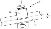
도 1은 본 발명의 바람직한 제1 실시예에 따른 트랜스컨넥터의 측면 사시도이다.
도 2는 도 1의 트랜스컨넥터의 상부 사시도이다.
도 3은 도 1의 트랜스컨넥터의 측 입면도이다.
도 4는 도 1의 트랜스컨넥터의 측 입면도로서, 부분적으로 팽창된 위치에 도시된다.
도 5는 도 1의 트랜스컨넥터의 상부 사시 확대도를 도시한다.
도 6a는 도 1의 트랜스컨넥터의 분절적 척추 봉 결합 부재의 상부 평면도로서, 분절적 척추 봉 결합 부재는 한쪽으로 흔들리는 방향으로 회동되어 척추 봉에 결합된다.
도 6b는 도 1의 트랜스컨넥터의 분절적 척추 봉 결합 부재의 정입면도로서, 분절적 척추 봉 결합 부재는 구름 방향에서 회동되어 척추 봉과 결합된다.
도 7은 본 발명의 바람직한 제2 실시예에 따른 트랜스컨넥터의 전방 확대 사시도이다.
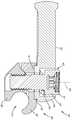
도 8은 도 7의 8-8선을 따른 도 7의 트랜스컨넥터의 단면도이다.
도 9a는 본 발명의 바람직한 제3 실시예에 따른 척추 봉들에 장착된 커플러 또는 트랜스컨넥터의 상부 사시도이다.
도 9b는 도 9a의 커플러의 확대도이다.
도 9c는 도 9a의 9C-9C선을 따라 취한, 도 9a의 커플러의 단면도이다.
도 10a은 본 발명의 바람직한 제4 실시예에 따른 트랜스컨넥터의 상부 사시도로서, 팽창된 위치에서 도시된다.
도 10b는 도 10a의 트랜스컨넥터의 상부 사시도로서, 부분적으로 붕괴된 위치에서 도시된다.
도 11은 도 10a의 트랜스컨넥터의 확대도이다.
도 12는 본 발명의 바람직한 제5 실시예에 따른 트랜스컨넥터의 측면 사시도이다.
도 13은 도 12의 트랜스컨넥터와 함께 사용되는 브리지 부재의 정입면도이다.The detailed description of the preferred embodiments of the present application, as well as the foregoing summary, will be better understood when read in conjunction with the accompanying drawings. For the purpose of describing the preferred transconnectors of the present application, drawings of preferred embodiments are shown. However, it should be understood that the present application should not be limited to the apparatus and tools shown.
1 is a side perspective view of a trans connector according to a first preferred embodiment of the present invention.
FIG. 2 is a top perspective view of the transconnector of FIG. 1. FIG.
3 is a side elevation view of the transconnector of FIG.
4 is a side elevation view of the transconnector of FIG. 1, shown in a partially expanded position.
FIG. 5 shows an enlarged top perspective view of the transconnector of FIG. 1. FIG.
FIG. 6A is a top plan view of the segmental spinal rod coupling member of the transconnector of FIG. 1, wherein the segmental spinal rod coupling member is pivoted in one direction and coupled to the spinal rod. FIG.
FIG. 6B is a front elevational view of the segmental spinal rod engaging member of the transconnector of FIG. 1, wherein the segmental spinal rod engaging member is pivoted in a rolling direction to engage the spinal rod.
7 is a front enlarged perspective view of a transconnector according to a second preferred embodiment of the present invention.
8 is a cross-sectional view of the transconnector of FIG. 7 along the 8-8 line of FIG.
9A is a top perspective view of a coupler or transconnector mounted on spinal rods in accordance with a third preferred embodiment of the present invention.
9B is an enlarged view of the coupler of FIG. 9A.
FIG. 9C is a cross-sectional view of the coupler of FIG. 9A, taken along
10A is a top perspective view of a transconnector according to a fourth preferred embodiment of the present invention, shown in an inflated position.
FIG. 10B is a top perspective view of the transconnector of FIG. 10A, shown in a partially collapsed position. FIG.
FIG. 11 is an enlarged view of the transconnector of FIG. 10A.
12 is a side perspective view of a trans connector according to a fifth exemplary embodiment of the present invention.
FIG. 13 is a front elevational view of the bridge member used with the transconnector of FIG. 12. FIG.
이어지는 상세한 설명에 사용된 특정의 용어는 편의성만을 위한 것이지 제한적이지는 않다. 단어들 "우", "좌", "상부", 및 "바닥"은 참조가 이루어진 도면들에서의 방향들을 나타낸다. 단어들 "내측으로" 및 "외측으로"는 장치 및 그 지정 부품들의 기하학적 중심을 향하거나 중심으로부터 벗어나는 방향들을 의미한다. 단어들 "전방", "후방", "위쪽", "아래쪽" 및 관련된 단어들 및/또는 구절은 참조가 된 인체에서 바람직한 위치들과 방위들을 나타내는 것이지 제한적인 의미를 가지는 것은 아니다. 용어들은 전술한 단어들, 그 파생어 유사한 의미를 가진 단어들을 포함한다.The specific terminology used in the description that follows is for the purpose of convenience only and not of limitation. The words "right", "left", "top", and "bottom" indicate directions in the figures to which reference is made. The words "inwardly" and "outwardly" refer to directions towards or away from the geometric center of the device and its designated parts. The words "forward", "rear", "up", "down" and related words and / or phrases indicate, but are not limited to, preferred positions and orientations in the referenced body. The terms include the words described above, and derivatives thereof.
도 1 내지 도 13을 참조하면, 특정의 예시적 실시예들은 도면들을 참조하여 설명될 것인 바, 동일한 참조부호들은 전체를 통틀어 동일한 구성요소들을 나타내는 데 사용된다. 일반적으로, 그러한 실시예들은 크로스-브레이스 또는 트랜스컨텍터 10, 10',200,300,400(집단적으로 본 명세서에서는 트랜스컨넥터로 명명됨)와 관련되며, 비-제한적인 예시에 의해, 트랜스컨넥터들 10,10',200,300,400은 바람직하게 배면 척추 고정 시술에서 한 쌍의 세로 척추 봉들을 상호 연결하는데 이용된다.1 to 13, certain exemplary embodiments will be described with reference to the drawings, wherein like reference numerals are used to denote like elements throughout. Generally, such embodiments relate to cross-braces or
트랜스컨넥터들 10,10',200,300,400은 다른 적용들과 용도들을 가질 수도 있으며 설명되고 도시된 구조나 용도에 한정되어서는 아니된다. 예를 들어, 트랜스컨넥터들 10,10',200,300,400은 하나의 척추 봉 5에만 결합되게 구성될 수 있는 한편, 트랜스컨넥터들 10,10',200,300,400의 다른 끝단은 예를 들어, 뼈 스크류를 경유하여 환자의 척추뼈에 직접 결합되게 구성되는 것도 상정할 수 있다.The
사용 시, 트랜스컨넥터들 10,10',200,300,400은 변화하는 척추 봉들 5의 정렬을 트랜스컨넥터들 10,10',200,300,400가 수용하는 것을 허용하는 다중의 자유도를 제공하도록 구성될 수 있다. 예를 들어, 트랜스컨넥터들 10,10',200,300,400은 척추 봉 5의 일단에 우선적으로 연결된 후 세로 척추 봉 5에 대해 각이 형성되어 이동됨으로써, 트랜스컨넥터들 10,10',200,300,400이 예를 들어, 수렴 및/또는 발산하는 세로 척추 봉들 5, 비-공면 세로 척추 봉 5, 및 변화하는 봉 분리 간격을 가진 세로 척추 봉들을 수용하는 것을 허용하도록 구성될 수 있다.In use, the
또한, 바람직한 트랜스컨넥터들 10,10',200,300,400은 대체적으로 척추(예를 들어, 요추, 경추 또는 흉추 영역)에 사용될 수 있는 것처럼 설명되었지만, 당업자들은 트랜스컨넥터들 10,10',200,300,400이 예를 들어, 관절, 긴 뼈 또는 손, 얼굴, 발 등에 있는 뼈와 같은 신체의 다른 부분들의 고정에 사용될 수 있음을 이해할 것이다.Further, although
바람직한 트랜스컨넥터들 10,10',200,300,400은 트랜스컨넥터들 10,10',200,300,400의 대체적인 모양을 취할 수 있고 트랜스컨넥터들 10,10',200,300,400의 정상 작동 상태를 견딜 수 있는 스테인리스 스틸, 티타늄 합금, 폴리머, 형상 기억 합금 등을 포함하지만 이에 한정되지 않는 그 어떤 다른 생체적합성 물질로부터 구성될 수 있다.
또한, 세로 척추 봉 5는 고체 봉, 비-고체 봉, 유연성 또는 동적 봉 등을 포함하지만 이에 한정되지 않을 수 있음을 이해해야 한다. 대안적으로, 세로 척추 봉 5는 전혀 봉이 아닐 수도 있으며, 예를 들어 플레이트의 형태일 수도 있다. 트랜스컨넥터들 10,10',200,300,400은 그 어떤 다른 특정 형태의 세로 척추 봉 5와 결합되어 사용되거나 그것과 조립체로서 사용되는 것에 한정되지 않음을 이해해야 한다.It should also be understood that longitudinal
도 1 내지 도 6b에 도시된 바람직한 제1 실시예를 참조하면, 트랜스컨넥터 10은 한 쌍의 척추 봉 결합 부재들 20과 브리지(bridge) 부재 75를 포함할 수 있다.Referring to the first preferred embodiment shown in FIGS. 1-6B, the
브리지 부재 75는 바람직하게 제1 부재 76과 제2 부재 78을 포함하고, 제1 및 제2 부재들 76,78은 서로에 대해 움직일 수 있고 변위 가능하기 때문에 트랜스컨넥터 10의 길이는 척추 봉 결합 부재들 20 사이의 간격을 변화시키도록 조절될 수 있고, 트랜스컨넥터 10은 세로 척추 봉들 5 사이의 다양한 간격들을 수용할 수 있다. 길이 조절 가능한 브리지 부재 75를 제공함으로써, 트랜스컨넥터 10은 다양한 중간-측면(medial-lateral) 조절을 허용할 수 있다. 대안적으로, 브리지 부재 75는 단일의, 조절할 수 없는 길이가 고정된 부재의 형태일 수 있다. 바람직한 제1 실시예에 있어서, 브리지 부재 75의 제1 및 제2 부재들 76,78은 접혀진(collapsed) 위치(도 3)와 팽창된 위치(미도시) 사이에서 이동하기 위해 서로에 대해 미끄러지게 장착된다. 그러나, 제1 및 제2 부재들 76,78은 서로 미끄러지게 장착되어 있는 것에 한정되지는 않으며 대안적으로, 서로에 대한 결합 부재들 20의 간격 및/또는 방위의 변형을 허용하도록 서로에 대해 장착될 수 있다.The
제1 및 제2 부재들 76,78은 예를 들어, 내부 봉이 외부 봉 내부에 신축 가능하게 수납된 외부 및 내부의 텔레스코픽(끼워 넣을 수 있는) 봉들을 포함하지만 이에 한정되지 않는 그 어떤 형태를 취할 수 있다. 대안적으로, 제1 및 제2 부재들 76,78은 길이 조절 가능한 브리지 부재 75를 제공하도록 서로에 대해 미끄러지는 측면의 나란한 부재들의 형태일 수도 있다. 제1 및 제2 부재들 76,78의 다른 배열들은 길이 조절 가능한 브리지 부재 75를 구성하도록 상정될 수도 있다. 그러나, 길이 조절 가능한 브리지 부재 75의 제1 및 제2 부재들 76,78은 바람직하게 각각 T-빔 80과 C-채널 82의 형태일 수 있으며, T-빔 80의 적어도 일 부분은 C-채널 82 내부에 미끄러지게 수납된다. 이러한 구성은 T-빔 80과 C-채널 82가 서로에 대해 측면으로 움직일 수 있게 하는 한편 꼬임 및/또는 회전을 실질적으로 방지할 수 있다. 바람직한 실시예에 있어서, 제1 및 제2 부재들 76,78은 측면으로 이동할 수 있는 한편 꼬임 및/또는 회전을 실질적으로 바람직하게 방지할 수 있는 다른 보완적인 모양들을 취할 수도 있음을 상정할 수 있다. 사용 시, 길이 조절 가능한 브리지 부재 75는 척추 봉 중심들 사이에서 대략 30mm 내지 대략 90mm의 조절을 허용할 수 있다.The first and
또한, 길이 조절 가능한 브리지 부재 75는 제1 및 제2 부재들 76,78의 서로에 대한 위치를 고정하기 위한 메커니즘을 포함할 수 있다. 메커니즘은 예를 들어, 볼트, 라체트, 클램프 등을 포함하지만 이에 한정되지 않은 현재 알려져 있거나 앞으로 알려질 그 어떤 메커니즘일 수 있다. 도시된 바와 같이, 길이 조절 가능한 브리지 부재 75는 바람직하게 제1 및 제2 부재들 76,78의 서로에 대한 위치를 고정하기 위해 필요한 클램핑 힘을 발생시킬 수 있는 이동 스크류 85를 포함한다.In addition, the
이동 스크류는, 바람직하게 그 혼자서 또는 길이 조절 가능한 브리지 부재 75에 형성된 특수 구조와 결합하여 구성되기 때문에 제1 및 제2 부재들 76,78은 풀려지거나 분리되는 것이 방지된다. 예를 들어, 이동 스크류 85는 바람직하게 "걸려져(staked)" 있기 때문에 이동 스크류 85는 제1 및 제2 부재 76,78로부터 제거될 수 없고 따라서 제1 및 제2 부재들 76,78의 분리가 방지된다.The movable screw is preferably configured alone or in combination with a special structure formed in the adjustable
제1 및 제2 부재들 76,78은 바람직하게 트랜스컨넥터 10이 예를 들어, 환자의 경뇌막(dura), 패싯(facets), 얇은 조각(lamina), 가시 돌기 등과 같은 인체의 골격 부분들을 걸치는 것을 허용하는 반경을 가진다. 바람직하게, 제1 및 제2 부재들 76,78은 대략 60mm의 반경을 가진다. 그렇지만 다른 반경들이 사용되는 것을 생각할 수 있다. 대안적으로, 제1 및 제2 부재들 76,78은 직선일 수 있다.The first and
트랜스컨넥터 10은 제1 및 제2 부재들 76,78에 작동 가능하게 연결되고, 각각 그 안에 세로 척추 봉들 5의 어느 하나를 수납하기 위한 봉 수납 채널 21을 포함하는 한 쌍의 척추 봉 결합 부재들 20을 포함한다. 트랜스컨넥터 10은 제1 및 제2 부재들 76,78에 작동 가능하게 각각 연결된 한 쌍의 분절 척추 봉 결합 부재들 22, 제1 및 제2 부재들 76,78에 작동 가능하게 각각 연결된 한 쌍의 비-분절 척추 봉 결합 부재 24, 또는 이들의 그 어떤 조합을 포함할 수 있다. 예를 들어, 도 1 내지 도 5에 가장 잘 도시된 바와 같이, 제1 및 제2 부재들 76,78의 어느 하나는 비-분절 척추 봉 결합 부재 24를 포함할 수 있는 한편 제1 및 제2 부재들 76,78의 다른 하나는 분절 척추 봉 결합 부재를 포함할 수 있다. 사용 시, 분절 척추 봉 결합 부재 22의 혼합은 척추 봉 결합 부재 20이 브리지 부재 75에 대해 관절이 형성되게(분절되게) 함으로써 척추 봉 결합 부재 20이 비-평행 방식으로 대체적으로 방향성을 가진 한 쌍의 척추 봉들 5와 결합하도록 한다. 바람직하게, 분절 척추 봉 결합 부재 22는, 도 6a에 가장 잘 도시된 바와 같이, 대략 플러스 마이너스 22도(±22°)의 한쪽으로 치우친(yaw) 방향으로 분절 각도를 형성시키는 한편, 도 6b에 가장 잘 도시된 바와 같이 구름(roll) 방향으로 플러스 마이너스 15도(±15°) 각도의 분절을 허용한다. 그렇지만 의미 있는 많거나 적은 분절이 허용될 수도 있다.
도 5에 가장 잘 도시된 바와 같이, 분절 척추 봉 결합 부재들 22는 상부 클램프 본체 30, 하부 클램프 본체 35, 압축 캡 45 및 작용 스크류 40을 포함할 수 있다. 바람직한 제1 실시예에 있어서, 상부 클램프 본체들 30의 적어도 어느 하나는 예를 들어, 상부 클램프 본체 30에 형성된 리세스 31에 의해 브리지 부재 75에 이동 가능하게 연결되고, 리세스 31은 브리지 부재 75의 적어도 어느 일단에 형성된 외부 곡면 또는 구형 표면 77과 결합하기 위한 내부 곡면 또는 구형 표면 32를 가지기 때문에 상부 클램프 본체 30은 곡면 또는 구형의 연결 표면을 통해 브리지 부재 75에 연결될 수 있다. 이러한 방식으로, 곡면 또는 구형의 연결 표면을 통해 브리지 부재 75에 상호 연결되는 상부 클램프 본체 30을 제공함에 의해, 상부 클램프 30은 브리지 부재 75에 대해 분절(관절)을 형성할 수 있기 때문에, 척추 봉 결합 부재 20은 세로 척추 봉들 5와 비-공면적으로 또는 비-평행하게 정렬된다. 압축 캡 45는 바람직하게, 브리지 부재 75에 형성된 외부 곡면 또는 구형 표면 77과 짝을 이루는 내부 곡면 또는 구형 표면 46을 포함한다.As best shown in FIG. 5, segmental spinal
하부 클램프 본체 35는 바람직하게, 예를 들어, 작용 스크류 40에 의해 상부 클램프 본체 30에 이동 가능하게 연결된다. 도시된 바와 같이, 브리지 부재 75, 상부 클램프 본체 30, 하부 클램프 본체 35 및 압축 캡 45는 바람직하게 모두 작용 스크류 40을 수납하기 위한 내부 보어 43을 포함한다. 즉, 바람직하게, 상부 클램프 본체 30, 하부 클램프 본체 35, 브리지 부재 75 및 압축 캡 45 모두는 작용 스크류 40을 수납하기 위한 보어 43을 포함하기 때문에 작용 스크류 40은 압축 캡 45, 상부 클램프 본체 30, 브리지 부재 75를 관통하여 하부 클램프 본체 35 속으로 나사 결합되고, 작용 스크류 40을 회전시키면 하부 클램프 본체 35가 상부 클램프 본체 30에 대해 움직이게 하여 봉 5를 봉 수납 채널 21 내부에 고정시켜 압축 캡 45에 형성된 내부 곡면 또는 구형 표면 46을 브리지 부재 75에 형성된 외부 곡면 또는 구형 표면 77에 대해 압축시켜 브리지 부재 75에 대한 분절 척추 봉 결합 부재들 22의 위치를 고정하게 된다. 따라서, 사용 시, 작용 스크류 40을 회전시키면 바람직하게, 하부 클램프 본체 35를 상부 클램프 본체 30 쪽으로 움직이게 함으로써 척추 봉 결합 부재 22가 척추 봉 5에 결합 될 때 척추 봉 결합 부재 20에 대한 척추 봉 5의 위치를 고정하게 된다. 또한, 작용 스크류 40의 회전은 브리지 부재 75에 대한 상부 및 하부 클램프 부재들 30,35의 위치를 고정한다(예, 브리지 부재 75에 대한 분절 척추 봉 결합 부재들 22의 구름 또는 한쪽으로 치우친 위치의 고정).The
비-일체적인 하부 클램프 본체 35의 통합에 의해, 척추 봉 결합 부재들 20 및 따라서 트랜스컨넥터 10은, 척추 봉 결합 부재들 20을 세로 척추 봉들 5에 부착시킴으로써 트랜스컨넥터 10이 낮은 프로파일을 얻는 것을 돕기 위해, 척추 봉 5의 전방에서의 보다 작은 척추 봉 간극을 필요로 한다. 대안적으로, 브리지 부재 75는 일체로 형성된 하부 클램프 본체(미도시)를 포함할 수도 있다.By incorporating the non-integral
사용 시, 작용 스크류 40은 바람직하게, 작용 스크류가 트랜스컨넥터 10으로부터 분리되는 것을 방지하기 위한 메커니즘을 포함한다. 예를 들어, 작용 스크류들 40은 "매달린(staked)" 끝단을 포함할 수 있기 때문에 작용 스크류들 40이 척추 봉 결합 부재들 20으로부터 제거되는 것이 어렵고 따라서 척추 봉 결합 부재들 20이 브리지 부재 75로부터 분리되는 것이 어렵다.In use, the
상부 및 하부 클램프 부재들 30,35는 바람직하게, 세로 척추 봉 5를 수납하기 위한 봉 수납 채널 21을 구획한다. 봉 수납 채널 21은 예를 들어, 척추 봉 결합 부재들 20에 대한 봉 5의 회전 또는 축방향 미끄러짐을 제한하기 위해 세로 척추 봉 5의 외부 표면과 접촉하기 위한 유리 구슬이 장식된 구조, 방사상의 톱니들, 톱니 모양들 등과 같은 거칠게 되어 있거나 무늬를 구조화된 표면을 포함할 수 있다.The upper and
또한, 척추 봉 결합 부재들 20은 바람직하게 스프링 50을 포함한다. 그렇지만, 스프링 50은 예를 들어, 나선 스프링, 판 스프링, 압축 스프링, 유연성 블록 등을 포함하는 현재 알려져 있거나 향후 알려질 그 어떤 형태들일 수 있다. 바람직한 제1 실시예에 있어서, 스프링 50은 스프링 와셔의 형태이다. 스프링 50은 바람직하게 반력(opposing force)를 제공하여 척추 봉 결합 부재들 20이 세로 척추 봉들 5에 임시적으로 스냅 결합되거나 아니면 일시적으로 결합되는 것을 허용한다. 즉, 스프링 50은 바람직하게 그곳을 통해 작용 스크류 40을 수납하기 위한 보어 52를 포함한다. 스프링 50은 바람직하게, 작용 스크류 40의 헤드 41과 압축 캡 45 또는 일체의 상부 클램프 본체 30 사이에 위치되기 때문에 스프링 50은 하부 클램프 부재 35를 상부 클램프 본체 30에 대하여 압축하는 바이어스 힘을 제공함으로써 세로 척추 봉 5는 척추 봉 결합 부재들 20에 형성된 봉 수납 채널들 21 내부에 임시적으로 또는 일시적으로 수납되어 고정될 수 있다. 스프링 50은 작용 스크류 40의 헤드의 하면에 바이어스 힘을 인가함으로써 하부 클램프 본체 35를 상부 클램프 본체 30 쪽으로 바이어스시켜 그곳에 결합시키게 되고, 작용 스크류 40에 있는 나사산들과 하부 클램프 본체 30의 보어 43에 있는 나사산들의 결합을 통해 하부 클램프 본체 35를 상부 클램프 본체 30 쪽으로 바이어스시킨다. 따라서, 바람직한 제1 실시예에서, 닫혀진 위치에서, 상대적으로 작은 직경을 가지는 봉 수납 채널 21을 구획하기 위해 하부 클램프 본체 35를 상부 클램프 본체 30 쪽으로 바이어스시키지만, 또한 스프링 50을 압축시키게 되면 하부 클램프 본체 35가 상부 클램프 본체 30으로부터 멀어지게 힘을 받는 것을 허용하여, 봉 5가 그 안에 수납되도록 봉 수납 채널 21을 확대시킬 수 있다.In addition, spinal
앞서 언급되고 도 1 내지 도 5에 가장 잘 도시된 바와 같이, 척추 봉 결합 부재들 20의 어느 하나 또는 모두는 비-분절 척추 봉 결합 부재 24로서 구성될 수 있다. 사용 시, 비-분절 척추 봉 결합 부재 24는 전술한 분절 척추 봉 결합 부재 22와 실질적으로 동일하지만, 비-분절 척추 봉 결합 부재 24에서, 상부 클램프 본체 30은 브리지 부재 75와 일체로 형성될 수 있다(브리지 부재 75의 제2 부재 78와 일체로 형성된 것으로 도시됨). 대안적으로, 상부 클램프 본체 30은 브리지 부재 75로부터 분리되어 별개의 것일 수 있고, 용접, 접착 결합, 클램핑, 체결 등과 같이 현재 알려져 있거나 앞으로 알려질 그 어떤 수단에 의해 그곳에 고정될 수 있음을 생각할 수 있다.As mentioned above and best shown in FIGS. 1-5, either or all of the spinal
또한, 사용 시, 작용 스크류 40의 회전은 바람직하게 브리지 부재 75에 대해 상부 및 하부 클램프 부재들 30,35의 위치를 고정하고(예, 브리지 부재 75에 대한 분절 척추 봉 결합 부재 22의 분절 위치(즉, 한쪽으로 치우치는 위치)를 고정함), 분절 척추 봉 결합 부재 22의 봉-수납 채널 21에 척추 봉 5를 고정하는 클램핑 힘을 제공한다. 비-분절 척추 봉-결합 부재 24의 경우, 작용 스크류 40의 회전은 바람직하게, 척추 봉 결합 부재 24의 봉 수납 채널 21에 척추 봉 5를 고정하기 위해 필요한 클램핑 힘을 제공하기만 한다.In use, the rotation of the
도 7 및 도 8을 참조하면, 바람직한 제2 실시예의 트랜스컨넥터 10'에 있어서, 브리지 부재 75'는 제1 및 제2 텔레스코픽, 관상 부재들(어느 하나만 도시됨)의 형태일 수 있고, 제1 부재는 제2 부재 내부에 수납되도록 구성된다. 대안적으로, 전술한 바와 같이, 트랜스컨넥터 10'는 하나의 척추 봉 5에만 직접 결합하기 위한 하나의 척추 봉 결합 부재 20'를 포함할 수 있는 한편, 트랜스컨넥터 10'의 타단은 예를 들어, 뼈 스크류를 통해 환자의 척추뼈에 직접 결합하도록 구성된다.7 and 8, in the
또한, 도시된 바와 같이, 척추 봉 결합 부재 20'은 브리지 부재 75'에 대해 쌓여진 관계로 위치될 수 있다. 즉, 예를 들어, 브리지 부재 75'는 상부 및 하부 클램프 본체들 30',35'의 상면 또는 어느 일측에 위치될 수 있다. 브리지 부재 75'는 작용 스크류 40'를 수납하기 위한 보어 43'을 가진 확경 끝단 90'을 포함할 수 있다. 상부 및 하부 클램프 본체들 30',35'는 바람직하게 브리지 부재 75'에 이동 가능하게 연결됨으로써 척추 봉 결합 부재들 20'은 바람직하게, 비-평행 및/또는 수렴/분산 봉들 5를 더 잘 수용하기 위해 작용 스크류 40'의 세로 축 42'에 대해 브리지 부재 75'와 회동되게 연결된다. 확경 끝단 90'의 바닥 표면 91'은 상부 클램프 본체 30'의 정상 표면 32'와 접촉하도록 구성될 수 있다. 확경 끝단들 90'의 바닥 표면 91'과 상부 클램프 본체 30'의 정상 표면 32'는 더 좋은 고정을 제공하기 위해 상응하는 톱니모양을 포함할 수 있다. 대안적으로, 확경 끝단들 90'의 바닥 표면 91'과 상부 클램프 본체 30'의 정상 표면 32'는 잠정적으로 향상된 고정을 제공하기 위해 표면 처리(거칠게 된 표면)될 수 있다.In addition, as shown, the spinal rod coupling member 20 'may be positioned in a stacked relationship with respect to the bridge member 75'. That is, for example, the bridge member 75 'may be located on the top or any one side of the upper and lower clamp bodies 30', 35 '. The bridge member 75 'may comprise a diameter end 90' with a bore 43 'for receiving the actuation screw 40'. The upper and lower clamp bodies 30 ', 35' are preferably movably connected to the bridge member 75 'so that the spinal rod coupling members 20' are preferably better able to receive non-parallel and / or converging / dispersing rods 5 '. In order to pivotally connect with the bridge member 75 'about the longitudinal axis 42' of the action screw 40 '. The bottom surface 91 'of the diaphragm end 90' may be configured to contact the top surface 32 'of the upper clamp body 30'. The bottom surface 91 'of the diaphragm ends 90' and the top surface 32 'of the upper clamp body 30' may include corresponding serrations to provide better fixation. Alternatively, the bottom surface 91 'of the diaphragm ends 90' and the top surface 32 'of the upper clamp body 30' may be surface treated (rough surface) to provide a potentially improved fixation.
또한, 척추 봉 결합 부재들 20'는 바람직하게 척추 봉 결합 부재들 20'에 형성된 봉 수납 채널들 21'에 대한 세로 척추 봉들 5의 임시적 스냅 결합을 허용하는 반력을 제공하는 스프링 50'를 포함한다. 전술한 바와 같이, 스프링 50'는 바람직하게 그곳을 통해 작용 스크류 40'를 수납하기 위한 보어 52'를 포함할 수 있다. 스프링 50'은 바람직하게, 도 7에 가장 잘 도시된 바와 같이, 작용 스크류 40'의 헤드 41'과 브리지 부재 75' 사이에 위치됨으로써, 스프링 50'은 하부 클램프 본체 35'를 상부 클램프 본체 30'에 대해 가압하는 초기 힘을 제공함으로써 세로 척추 봉 5는 봉 수납 채널 21' 내부에 임시적으로 또는 일시적으로 수납되어 고정될 수 있다. 스프링 50'는 스프링 와셔를 포함하지만 이에 한정되지 않는 현재 알려져 있거나 또는 앞으로 알려질 그 어떤 형태일 수 있다. 스프링 50'는 바람직하게 척추 봉 결합 부재 20'가 세로 척추 봉들 5에 대한 임시적인 스냅 결합을 허용하는 반력을 제공한다.The spinal rod coupling members 20 'also preferably include a spring 50' that provides a reaction force allowing temporary snap engagement of the longitudinal
트랜스컨넥터 10'의 동작은 전술한 트랜스컨넥터 10의 작동과 실질적으로 유사하다.The operation of Transconnector 10 'is substantially similar to the operation of
대안적으로, 도 9a 내지 도 9c에 도시된 바와 같이, 실질적으로 평행한 봉들 205를 상호 연결하기 위한 바람직한 제3 실시예에 따른 커플러 또는 트랜스컨넥터 200이 개시된다. 사용 시, 커플러 200은 실질적으로 평행한 교차 척추 봉들 5를 연결하는 트랜스컨넥터로서 사용될 수 있다. 대안적으로, 커플러 200은 실질적으로 평행한 세로 척추 봉들 5를 연결하는 트랜스컨넥터로서 사용될 수 있다. 또한, 커플러 200은 긴 뼈들의 내부 또는 외부 고정을 포함하지만 이에 한정되지 않는 실질적으로 평행한 봉들을 연결하는 신체의 다른 부분들에 사용될 수도 있다.Alternatively, as shown in FIGS. 9A-9C, a coupler or
커플러 200은 바람직하게 상부 클램프 본체 230, 하부 클램프 본체 235, 하나 또는 그 이상의 작용 스크류들 240, 및 하나 또는 그 이상의 스프링들 250을 포함한다. 커플러 200의 동작은 전술한 트랜스컨넥터들 10,10'의 동작과 실질적으로 동일하다. 즉, 하부 클램프 본체 235는 바람직하게 예를 들어, 작용 스크류 240에 의해 상부 클램프 본체 230에 이동 가능하게 연결된다. 바람직하게, 상부 클램프 본체 230과 하부 클램프 본체 235는 작용 스크류 240을 수납하는 내부 보어 243을 포함한다. 상부 및 하부 클램프 본체들 230,235는 세로 척추 봉들 205를 수납하기 위한 봉 수납 채널 221을 구획한다. 사용 시, 작용 스크류 240의 회전은 하부 클램프 본체 235를 상부 클램프 본체 230 쪽으로 이동시키게 함으로써, 척추 봉들 205가 봉 수납 채널 221에 위치될 때, 커플러 200에 대한 척추 봉들 205의 위치를 고정하게 된다.
스프링 250은 바람직하게 세로 척추 봉들 205가 커플러 200에 형성된 봉 수납 채널들 221에 대한 임시적 스냅 결합을 허용하는 반력을 제공한다. 스프링 250은 바람직하게 그곳을 통해 작용 스크류 240을 수납하기 위한 보어 252를 가진 스프링 와셔의 형태일 수 있다. 스프링 250은 바람직하게 작용 스크류 240의 헤드 241과 상부 클램프 본체 235 사이에 위치됨으로써 하부 클램프 본체 235가 상부 클램프 본체 230에 대항하여 가압하는 초기 힘을 제공함으로써 세로 척추 봉 205는 커플러 200에 형성된 봉 수납 채널 221 내부에 임시적으로 수납되어 고정될 수 있다. 스프링 250은 전술한 바와 같이, 많은 다른 형태일 수 있다.
바람직한 제4 실시예의 트랜스컨넥터 300은 도 10a 내지 도 11에 도시된다. 바람직한 제4 실시예에 있어서, 브리지 부재 375는 제1 및 제2 부재들 376,378의 형태일 수 있으며, 제1 부재 376은 제2 부재 378에 회동되게 연결되거나 힌지 결합된다. 제1 부재 376은 바람직하게 팽창된 위치에서 구획되는 트랜스컨넥터 300의 세로 축 388에 실질적으로 교차할 수 있는 회동 축 386을 통해 제2 부재 378에 회동되게 연결되거나 힌지 결합됨으로써, 제1 및 제2 부재들 376,378의 회동 조절은 브리지 부재 375가 해부학적 축 평면에서 굴곡되게 한다. 이러한 방식으로, 제2 부재 378에 대한 제1 부재 376의 회동 가능한 조절은 바람직하게 트랜스컨넥터 300의 길이 또는 트랜스컨넥터 300의 어느 한 끝단에서 척추 봉 결합 부재들 320 사이의 간격을 변경시킨다. 제2 부재 378에 대한 제1 부재의 회동 조절은 브리지 부재 375가 배면으로 움직이는 것을 허용함으로써 도 10b에 가장 잘 도시된 바와 같이, 트랜스컨넥터 300의 전체 길이를 짧게 한다.A
제1 및 제2 부재들 376,378은 제1 및 제2 부재들 376,378이 서로에 대해 회동하는 것을 허용하는 현재 알려진 또는 앞으로 알려질 그 어떤 다른 수단에 의해 서로 연결될 수 있다. 바람직하게, 제2 부재 378은 그 안에 형성된 구멍 392를 포함하고, 구멍 392는 제1 부재 376으로부터 측방으로 연장하는 돌기 390을 수납한다. 돌기 390은 바람직하게 다수의 탭들 391을 포함한다. 또한, 브리지 부재 375는 바람직하게 나사산이 형성된 파스너 또는 세트 스크류 394를 포함한다. 세트 스크류 394는 제1 부재 376과 나사 결합될 수 있으므로 세트 스크류 394의 회전은 돌기 390, 보다 바람직하게 다수의 탭들 392를 팽창시킴으로써, 탭들 392가 구멍 392의 내부 표면에 힘을 가하게 함으로써 제2 부재 378에 대한 제1 부재 376의 위치를 고정하게 된다.The first and
제1 및 제2 부재들 376,378은 바람직하게 일체의 척추 봉 결합 부재들 320을 포함하지만 그에 한정되지는 않는다. 척추 봉 결합 부재들 320은 세로 척추 봉 5를 수납하는 봉 수납 채널 321을 포함한다. 또한, 척추 봉 결합 부재들 320은 척추 봉 결합 부재 320의 봉 수납 채널 321에 척추 봉 5를 고정하기 위한 웨지 부재 324(예, 세트 스크류)를 수납하는 관통보어 322를 포함한다. 대안적으로, 트랜스컨넥터 300은 비-일체형 척추 봉 결합 부재들 320을 포함할 수 있음을 생각해 볼 수 있다.The first and
바람직한 제5 실시예의 트랜스컨넥터 400가 도 12 및 도 13에 도시되어 있다. 제5 실시예에 있어서, 브리지 부재 475는 제1 및 제2 부재들 476,478의 형태일 수 있고, 제1 부재 476과 제2 부재 478은 서로에 대해 측방으로 조절될 수 있다. 그렇지만, 제1 및 제2 부재들 476,478은 그 어떤 형태일 수 있으며, 바람직하게 도시된 바와 같이, 제1 및 제2 부재들 476,478은 각각 그곳으로부터 확장하는 포스트 460을 포함하는 비-분절 척추 봉 결합 부재 420의 형태일 수 있다. 또한, 척추 봉 결합 부재들 420은 그곳을 관통하는 관통보어 462를 포함하고, 관통보어 462는 다른 척추 봉 결합 부재 420으로부터 연장하는 포스트 460을 수납한다.A
척추 봉 결합 부재들 420은 바람직하게 예를 들어, 전술한 바와 같은 작용 스크류 440에 의해 상부 클램프 본체 430에 이동되게 연결된 분리된, 비-일체형 하부 클램프 본체 435를 포함한다.The spinal
사용 시, 작용 스크류 440의 회전은 바람직하게 (i) 상부 클램프 본체 430에 대한 하부 클램프 본체 435의 위치를 고정함으로써 봉 수납 채널 421 내부에 세로 척추 봉 5의 위치를 고정하고 (ii) 제1 부재 476에 대한 제2 부재 478의 위치를 고정한다. 즉, 도 13에 가장 잘 도시된 바와 같이, 제1 및 제2 부재들 476,478은 바람직하게 그 안에 형성된 슬롯 464를 포함하기 때문에 작용 스크류 440의 회전은 척추 봉 결합 부재들 420이 서로 엇갈리는 척추 봉 결합 부재 420의 포스트 460에 대항하여 압축을 허용함으로써 제2 부재 478에 대한 제1 부재 476의 위치를 고정하게 된다.In use, rotation of the
전술한 바와 같이, 상부 및 하부 클램프 본체들 430,435는 바람직하게 세로 척추 봉 5를 수납하기 위해 그 안에 형성된 봉 수납 채널 421을 포함한다. 봉 수납 채널 421은 척추 봉 결합 부재들 420에 대한 봉 5의 회전 또는 축방향 미끄러짐을 방지하기 위하여 세로 척추 봉 5의 외부 표면과 결합하기 위해 예를 들어, 유리 구슬 구조, 방사상의 톱니, 톱니모양, 그루브 등과 같은 표면 처리 또는 구조 표면을 포함할 수 있다.As mentioned above, the upper and
또한, 전술한 바와 같이, 척추 봉 결합 부재들 420의 상부 및 하부 클램프 본체들 430,435는 바람직하게 각각 척추 봉 결합 부재들 420이 세로 척추 봉들 5에 임시적인 스냅 결합을 허용하는 반력을 제공하는 스프링 450을 포함한다.Further, as described above, the upper and
또한, 제1 및 제2 부재들 476,478은 바람직하게 제1 및 제2 부재들 476,478의 분리를 방지하는 특수 구조를 포함한다. 예를 들어, 포스트 460은 제1 및 제2 부재들 476,478이 서로에 대해 이탈하는 것을 제한하는 확대된 끝단들을 포함할 수 있다.In addition, the first and
전술한 상세한 설명 및 도면들은 본 발명의 바람직한 실시예들을 나타내지만, 첨부된 청구의 범위에 의해 정의된 바와 같이 본 발명의 정신 및 범위를 벗어나지 않는 한 본 발명의 다양한 부가, 변형, 조합 및/또는 대체들이 가능함을 이해할 것이다. 예를 들어, 많은 브리지 부재들 및/또는 척추 봉 결합 부재들이 본 명세서에 개시되어 있지만, 다른 브리지 부재들 및 척추 봉 결합 부재들이 혼합되거나 짝을 이룰 수 있으므로 모든 브리지 부재는 각각의 그리고 모든 척추 봉 결합 부재와 함께 사용되도록 구성될 수 있다. 특히, 본 발명은 그 기본적인 특징 또는 정신을 벗어나지 않는 한, 다른 특정의 형태, 구조, 배열, 비례, 및 다른 구성요소들, 물질들, 성분들에 구체화될 수 있음을 당업자는 잘 이해할 것이다.While the foregoing description and drawings illustrate preferred embodiments of the invention, various additions, modifications, combinations and / or changes of the invention may be made without departing from the spirit and scope of the invention as defined by the appended claims. It will be understood that alternatives are possible. For example, although many bridge members and / or spinal rod coupling members are disclosed herein, all bridge members are each and every spinal rod as other bridge members and spinal rod coupling members can be mixed or paired. It may be configured for use with the engagement member. In particular, those skilled in the art will appreciate that the present invention can be embodied in other specific forms, structures, arrangements, proportions, and other components, materials, components, without departing from its basic features or spirit.
5...척추 봉 10,10',200,300,400...트랜스컨넥터
20...척추 봉 결합 부재들 22...분절 척추 봉 결합 부재
24...비-분절 척추 봉 결합 부재 30...상부 클램프 본체
31...리세스 35...하부 클램프 본체
32, 77...구형 표면 40...작용 스크류
41...헤드 43...보어
45...압축 캡 75...브리지 부재
76...제1 부재 78...제2 부재
80...T-빔 82...C-채널
85...이동 스크류5 ...
20 ... vertical
24 ... Non-segmental spinal
31
32, 77 ...
41 ...
45 ...
76 ...
80 ... T-
85 ... moving screw
Claims (13)
Translated fromKorean제1 끝단 및 제2 끝단을 가진 브리지(bridge) 부재; 및
제1 및 제2 봉 결합 부재들을 구비하고,
상기 제1 봉 결합 부재는 상기 브리지 부재의 상기 제2 끝단에 연결되고, 상기 제1 및 제2 봉 결합 부재들 각각은 상기 제1 및 제2 봉들의 어느 하나를 그 안에 수납하기 위한 봉 수납 채널을 포함하고, 적어도 상기 제1 봉 결합 부재는 상기 브리지 부재에 대해 분절 가능하고(관절로 이어질 수 있고), 상기 제1 봉 결합 부재는 상부 클램프 본체, 하부 클램프 본체, 작용 스크류, 압축 캡 및 스프링을 포함하고, 상기 브리지 부재의 상기 제1 끝단은 상기 작용 스크류를 수납하기 위한 보어를 포함함으로써 상기 작용 스크류가 상기 스프링, 상기 압축 캡, 상기 상부 클램프 본체, 상기 브리지 부재의 상기 제1 끝단을 관통하여 상기 하부 클램프 본체 속으로 나사 결합될 수 있고, 상기 작용 스크류의 회전은 상기 상부 클램프 본체에 대해 상기 하부 클램프 본체를 이동시킴으로써 상기 봉을 상기 봉 수납 채널에 고정시켜 상기 브리지 부재에 대한 상기 제1 봉 결합 부재의 위치를 고정시키고, 상기 스프링은 상기 하부 클램프 본체를 상기 상부 클램프 본체 쪽으로 바이어스함으로써 상기 제1 봉 결합 부재가 상기 봉 수납 채널 내부에 수납된 상기 봉에 임시적으로 스냅 결합될 수 있는 것을 특징으로 하는 트랜스컨넥터.In a transconnector for interconnecting the first and second rods:
A bridge member having a first end and a second end; And
Having first and second rod coupling members,
The first rod coupling member is connected to the second end of the bridge member, and each of the first and second rod coupling members is a rod receiving channel for receiving one of the first and second rods therein. Wherein at least the first rod coupling member is segmentable (may lead to a joint) with respect to the bridge member, and the first rod coupling member comprises an upper clamp body, a lower clamp body, an acting screw, a compression cap and a spring Wherein the first end of the bridge member includes a bore for receiving the action screw such that the action screw passes through the spring, the compression cap, the upper clamp body, and the first end of the bridge member. Can be screwed into the lower clamp body, and rotation of the acting screw causes the lower clamp body to rotate relative to the upper clamp body. Move the rod to secure the rod to the rod receiving channel to fix the position of the first rod coupling member relative to the bridge member, and the spring biases the lower clamp body towards the upper clamp body, thereby And may be temporarily snapped to the rod housed within the rod receiving channel.
상기 스프링은 그곳을 통해 상기 작용 스크류를 수납하기 위한 보어를 가진 스프링 와셔를 구비하는 것을 특징으로 하는 트랜스컨넥터.The method of claim 1,
And the spring has a spring washer having a bore for receiving the actuation screw therethrough.
상기 스프링 와셔는 (i) 상기 작용 스크류와 상기 압축 캡; (ii) 상기 작용 스크류와 상기 상부 클램프 본체, 및 (iii) 상기 브리지 부재와 상기 상부 클램프 본체의 어느 하나의 사이에 위치되는 것을 특징으로 하는 트랜스컨넥터.The method of claim 2,
The spring washer comprises (i) the acting screw and the compression cap; and (ii) the actuating screw and the upper clamp body, and (iii) between the bridge member and the upper clamp body.
상기 상부 클램프 본체는 상기 브리지 부재의 상기 제1 끝단에 형성된 외부 굴곡 표면과 결합하기 위한 내부 굴곡 표면을 가진 리세스(recess)를 포함하기 때문에 상기 상부 클램프 본체가 굴곡 연결 표면을 통해 상기 브리지 부재의 상기 제1 끝단에 연결되는 것을 특징으로 하는 트랜스컨넥터.The method of claim 1,
Since the upper clamp body includes a recess having an inner bent surface for engaging with an outer bent surface formed at the first end of the bridge member, the upper clamp body is connected to the bridge member through a bent connection surface. Transconnector, characterized in that connected to the first end.
상기 제1 봉 결합 부재는 한쪽으로 치우친(yaw) 방향 및 구름(roll) 방향으로 분절(articulation) 가능한 것을 특징으로 하는 트랜스컨넥터.The method of claim 1,
And the first rod coupling member is capable of articulation in a yaw direction and a roll direction to one side.
상기 제2 봉 결합 부재는 상기 브리지 부재에 대해 분절 가능한 것을 특징으로 하는 트랜스컨넥터.The method of claim 1,
And the second rod coupling member is segmentable with respect to the bridge member.
상기 제2 봉 결합 부재의 적어도 일 부분은 상기 브리지 부재의 상기 제2 끝단과 일체로 형성된 것을 특징으로 하는 트랜스컨넥터.The method of claim 1,
At least a portion of the second rod coupling member is integrally formed with the second end of the bridge member.
상기 브리지 부재는 제1 부재와 제2 부재를 포함하고, 상기 제1 및 제2 부재들은 서로에 대해 이동 가능하게 옮겨질 수 있으므로 상기 브리지 부재의 길이가 조절될 수 있으며;
상기 브리지 부재는 상기 제1 및 제2 부재들의 길이를 서로에 대해 고정하기 위한 메커니즘을 더 구비하는 것을 특징으로 하는 트랜스컨넥터.The method of claim 1,
The bridge member includes a first member and a second member, and the length of the bridge member can be adjusted because the first and second members can be moved to move relative to each other;
And the bridge member further comprises a mechanism for fixing the lengths of the first and second members relative to each other.
상기 제1 및 제2 부재들은 외부 및 내부의 신축 가능한(telescopic) 봉들이고 상기 내부 봉은 상기 외부 봉에 신축 가능하게 수납된 것을 특징으로 하는 트랜스컨넥터.The method of claim 8,
And the first and second members are telescopic rods inside and outside and the inner rod is elastically housed in the outer rod.
상기 제1 및 제2 부재들의 하나는 T-빔(beam)이고, 상기 제1 및 제2 부재들의 다른 하나는 C-채널이며, 상기 T-빔은 상기 C-채널 내부에 미끄러지게 수납 가능하게 되어 있으므로 상기 브리지 부재의 길이가 조절 가능한 한편 상기 제1 및 제2 부재들의 측면 및 회전 이동은 서로에 대해 제한되는 것을 특징으로 하는 트랜스컨넥터.The method of claim 8,
One of the first and second members is a T-beam, the other of the first and second members is a C-channel, and the T-beam is slidably housed inside the C-channel. Wherein the length of the bridge member is adjustable while the lateral and rotational movement of the first and second members is limited relative to each other.
상기 제1 및 제2 부재들의 길이를 고정하기 위한 상기 메커니즘은 브리지 부재 이동 스크류인 것을 특징으로 하는 트랜스컨넥터.The method of claim 8,
And the mechanism for fixing the length of the first and second members is a bridge member moving screw.
상기 브리지 부재는 곡률 반경을 포함하는 것을 특징으로 하는 트랜스컨넥터.The method of claim 8,
And the bridge member comprises a radius of curvature.
상기 적어도 하나의 분절 가능한 봉 결합 부재는 상기 브리지 부재에 대해 회동되게 연결된 것을 특징으로 하는 트랜스컨넥터.The method of claim 1,
And the at least one segmentable rod coupling member is pivotally connected with respect to the bridge member.
Applications Claiming Priority (2)
| Application Number | Priority Date | Filing Date | Title |
|---|---|---|---|
| US97507107P | 2007-09-25 | 2007-09-25 | |
| US60/975,071 | 2007-09-25 |
Publications (2)
| Publication Number | Publication Date |
|---|---|
| KR20100074121Atrue KR20100074121A (en) | 2010-07-01 |
| KR101567593B1 KR101567593B1 (en) | 2015-11-09 |
Family
ID=40040080
Family Applications (1)
| Application Number | Title | Priority Date | Filing Date |
|---|---|---|---|
| KR1020107005101AExpired - Fee RelatedKR101567593B1 (en) | 2007-09-25 | 2008-09-24 | transconnector |
Country Status (14)
| Country | Link |
|---|---|
| US (4) | US8262701B2 (en) |
| EP (1) | EP2190368B1 (en) |
| JP (1) | JP5466160B2 (en) |
| KR (1) | KR101567593B1 (en) |
| CN (1) | CN101873835B (en) |
| AT (1) | ATE499059T1 (en) |
| AU (1) | AU2008304546A1 (en) |
| BR (1) | BRPI0817238A2 (en) |
| CA (1) | CA2698970A1 (en) |
| CO (1) | CO6260038A2 (en) |
| DE (1) | DE602008005162D1 (en) |
| ES (1) | ES2359604T3 (en) |
| PL (1) | PL2190368T3 (en) |
| WO (1) | WO2009042653A1 (en) |
Cited By (1)
| Publication number | Priority date | Publication date | Assignee | Title |
|---|---|---|---|---|
| DE102013000918A1 (en) | 2012-01-16 | 2013-07-18 | Mando Corp. | Combination structure for shock absorbers |
Families Citing this family (70)
| Publication number | Priority date | Publication date | Assignee | Title |
|---|---|---|---|---|
| US7744635B2 (en)* | 2004-06-09 | 2010-06-29 | Spinal Generations, Llc | Spinal fixation system |
| WO2006058221A2 (en) | 2004-11-24 | 2006-06-01 | Abdou Samy M | Devices and methods for inter-vertebral orthopedic device placement |
| EP1971282A2 (en) | 2006-01-10 | 2008-09-24 | Life Spine, Inc. | Pedicle screw constructs and spinal rod attachment assemblies |
| US8568453B2 (en)* | 2007-01-29 | 2013-10-29 | Samy Abdou | Spinal stabilization systems and methods of use |
| US8603141B2 (en)* | 2007-09-19 | 2013-12-10 | Pioneer Surgical Technology, Inc. | Intervertebral implant devices and methods for insertion thereof |
| US8292924B2 (en)* | 2007-10-05 | 2012-10-23 | Spineworks, Llc | Enhanced pedicle rod clamp device |
| US9060813B1 (en) | 2008-02-29 | 2015-06-23 | Nuvasive, Inc. | Surgical fixation system and related methods |
| EP2421454A4 (en)* | 2009-04-23 | 2013-12-11 | Spinal Elements Inc | Transverse connectors |
| US8246657B1 (en) | 2009-06-29 | 2012-08-21 | Nuvasive, Inc. | Spinal cross connector |
| US8568456B2 (en)* | 2009-09-21 | 2013-10-29 | Globus Medical, Inc. | Transverse connector having a locking element for capturing multiple rods |
| US8764806B2 (en) | 2009-12-07 | 2014-07-01 | Samy Abdou | Devices and methods for minimally invasive spinal stabilization and instrumentation |
| WO2011069963A2 (en)* | 2009-12-10 | 2011-06-16 | Kilian Kraus | Rod connector |
| US9198696B1 (en) | 2010-05-27 | 2015-12-01 | Nuvasive, Inc. | Cross-connector and related methods |
| US20120271353A1 (en)* | 2010-08-16 | 2012-10-25 | Mark Barry | System and method for aligning vertebrae in the amelioration of aberrant spinal column deviation conditions in patients requiring the accomodation of spinal column growth or elongation |
| US9504495B2 (en) | 2011-02-11 | 2016-11-29 | Blackstone Medical, Inc. | Multi-axial pedicle fixation assembly and method for use |
| US9387013B1 (en) | 2011-03-01 | 2016-07-12 | Nuvasive, Inc. | Posterior cervical fixation system |
| US9247964B1 (en) | 2011-03-01 | 2016-02-02 | Nuasive, Inc. | Spinal Cross-connector |
| CA2831081A1 (en) | 2011-04-07 | 2012-10-11 | Mike Hammer | Clamp for spinal cross connecting device |
| JP6106662B2 (en)* | 2011-05-17 | 2017-04-05 | ジンマー,インコーポレイティド | External fixed clamping system using a starting mechanism and stored spring energy |
| US9005249B2 (en) | 2011-07-11 | 2015-04-14 | Life Spine, Inc. | Spinal rod connector assembly |
| US9339305B2 (en) | 2011-09-19 | 2016-05-17 | DePuy Synthes Products, Inc. | Snap fit rod and fastener system |
| US8845728B1 (en) | 2011-09-23 | 2014-09-30 | Samy Abdou | Spinal fixation devices and methods of use |
| US8758411B1 (en) | 2011-10-25 | 2014-06-24 | Nuvasive, Inc. | Implants and methods for treating spinal disorders |
| US8740950B2 (en) | 2011-12-08 | 2014-06-03 | Spine Wave, Inc. | Methods for percutaneously attaching a cross connector to contralateral spinal constructs |
| US9125691B2 (en)* | 2011-12-23 | 2015-09-08 | Amendia, Inc. | Transverse crosslink device |
| US8945186B2 (en)* | 2011-12-30 | 2015-02-03 | Blackstone Medical, Inc. | Multi-axial spinal cross connecting device |
| US8556942B2 (en) | 2011-12-30 | 2013-10-15 | Blackstone Medical, Inc. | Occipito-cervical fixation assembly and method for constructing same |
| US20130226240A1 (en) | 2012-02-22 | 2013-08-29 | Samy Abdou | Spinous process fixation devices and methods of use |
| US8940020B2 (en) | 2012-04-06 | 2015-01-27 | DePuy Synthes Products, LLC | Rod connector |
| US9198767B2 (en) | 2012-08-28 | 2015-12-01 | Samy Abdou | Devices and methods for spinal stabilization and instrumentation |
| US9055982B2 (en)* | 2012-09-25 | 2015-06-16 | Warsaw Orthopedic, Inc. | Spinal implant system and methods of use |
| US9320617B2 (en) | 2012-10-22 | 2016-04-26 | Cogent Spine, LLC | Devices and methods for spinal stabilization and instrumentation |
| US9936982B2 (en) | 2012-11-26 | 2018-04-10 | Spinefrontier, Inc | System and method for translateral linking of bilateral spinal fixation rods |
| JP5998890B2 (en)* | 2012-12-06 | 2016-09-28 | 富士通株式会社 | Spring washers and fixtures |
| WO2014172445A1 (en) | 2013-04-17 | 2014-10-23 | Ebi, Llc | Cross connector system |
| US20150073488A1 (en)* | 2013-09-09 | 2015-03-12 | James A. Rinner | Spinal stabilization system |
| US9681903B2 (en)* | 2013-11-15 | 2017-06-20 | K2M, Inc. | Clip for dynamic spinal plate |
| CN104287818B (en)* | 2014-10-29 | 2017-04-19 | 刘忠军 | Length-adjustable vertebral plate |
| WO2016107585A1 (en)* | 2014-12-30 | 2016-07-07 | 苏州天臣国际医疗科技有限公司 | Nail head assembly and suturing and cutting apparatus for endoscopic surgery |
| US10857003B1 (en) | 2015-10-14 | 2020-12-08 | Samy Abdou | Devices and methods for vertebral stabilization |
| US10321939B2 (en)* | 2016-05-18 | 2019-06-18 | Medos International Sarl | Implant connectors and related methods |
| US10517647B2 (en) | 2016-05-18 | 2019-12-31 | Medos International Sarl | Implant connectors and related methods |
| US10363073B2 (en) | 2016-07-13 | 2019-07-30 | Medos International Sàrl | Bone anchor assemblies and related instrumentation |
| US10568667B2 (en) | 2016-07-13 | 2020-02-25 | Medos International Sàrl | Bone anchor assemblies and related instrumentation |
| US10463402B2 (en) | 2016-07-13 | 2019-11-05 | Medos International Sàrl | Bone anchor assemblies and related instrumentation |
| US10874438B2 (en) | 2016-07-13 | 2020-12-29 | Medos International Sarl | Bone anchor assemblies and related instrumentation |
| US10973648B1 (en) | 2016-10-25 | 2021-04-13 | Samy Abdou | Devices and methods for vertebral bone realignment |
| US10744000B1 (en) | 2016-10-25 | 2020-08-18 | Samy Abdou | Devices and methods for vertebral bone realignment |
| KR101910597B1 (en)* | 2016-12-02 | 2018-10-22 | 안경기 | Rod connector |
| US10398476B2 (en) | 2016-12-13 | 2019-09-03 | Medos International Sàrl | Implant adapters and related methods |
| US10492835B2 (en) | 2016-12-19 | 2019-12-03 | Medos International Sàrl | Offset rods, offset rod connectors, and related methods |
| US10413331B2 (en) | 2016-12-21 | 2019-09-17 | Spine Wave, Inc. | Spinal stabilization system with head to head cross connector |
| CN106510823A (en)* | 2016-12-28 | 2017-03-22 | 上海凯利泰医疗科技股份有限公司 | Universal transverse connector |
| US10238432B2 (en) | 2017-02-10 | 2019-03-26 | Medos International Sàrl | Tandem rod connectors and related methods |
| US10966761B2 (en)* | 2017-03-28 | 2021-04-06 | Medos International Sarl | Articulating implant connectors and related methods |
| US10561454B2 (en) | 2017-03-28 | 2020-02-18 | Medos International Sarl | Articulating implant connectors and related methods |
| WO2019051260A1 (en) | 2017-09-08 | 2019-03-14 | Pioneer Surgical Technology, Inc. | Intervertebral implants, instruments, and methods |
| USD907771S1 (en) | 2017-10-09 | 2021-01-12 | Pioneer Surgical Technology, Inc. | Intervertebral implant |
| US11076890B2 (en) | 2017-12-01 | 2021-08-03 | Medos International Sàrl | Rod-to-rod connectors having robust rod closure mechanisms and related methods |
| US11179248B2 (en) | 2018-10-02 | 2021-11-23 | Samy Abdou | Devices and methods for spinal implantation |
| CN113164193A (en)* | 2018-12-14 | 2021-07-23 | 捷迈拜欧米特Cmf和胸腔有限公司 | Bone fixation and repair system |
| US11612418B2 (en) | 2019-12-13 | 2023-03-28 | Globus Medical, Inc. | Revision connectors, systems, and methods thereof |
| CN111759437A (en)* | 2020-07-28 | 2020-10-13 | 苏州优贝特医疗器械有限公司 | A card slot adjustable universal cross connector |
| US12213706B2 (en) | 2020-10-07 | 2025-02-04 | Globus Medical, Inc. | Systems and methods for surgical procedures using band clamp implants and tensioning instruments |
| US11771475B2 (en) | 2020-10-07 | 2023-10-03 | Globus Medical, Inc. | Systems and methods for surgical procedures using band clamp implants and tensioning instruments |
| US11974785B2 (en) | 2020-10-16 | 2024-05-07 | Globus Medical, Inc | Band clamp implants |
| US11426211B2 (en) | 2020-10-28 | 2022-08-30 | Globus Medical, Inc. | Articulating connectors, systems, and methods thereof |
| KR20220059862A (en)* | 2020-11-03 | 2022-05-10 | 주식회사 솔고 바이오메디칼 | Rod connector device for cervical spine |
| US11331125B1 (en) | 2021-10-07 | 2022-05-17 | Ortho Inventions, Llc | Low profile rod-to-rod coupler |
| JP2025529435A (en)* | 2022-09-13 | 2025-09-04 | メドス・インターナショナル・エスエイアールエル | Modular Connector Assembly |
Family Cites Families (34)
| Publication number | Priority date | Publication date | Assignee | Title |
|---|---|---|---|---|
| WO1991016020A1 (en)* | 1990-04-26 | 1991-10-31 | Danninger Medical Technology, Inc. | Transpedicular screw system and method of use |
| US5330473A (en)* | 1993-03-04 | 1994-07-19 | Advanced Spine Fixation Systems, Inc. | Branch connector for spinal fixation systems |
| WO1998008454A1 (en)* | 1994-05-25 | 1998-03-05 | Jackson Roger P | Apparatus and method for spinal fixation and correction of spinal deformities |
| CH690293A5 (en)* | 1994-09-06 | 2000-07-14 | Jaquet Orthopedie | Joint for components of an external fixator. |
| US5716355A (en)* | 1995-04-10 | 1998-02-10 | Sofamor Danek Group, Inc. | Transverse connection for spinal rods |
| US5947966A (en)* | 1995-06-06 | 1999-09-07 | Sdgi Holdings, Inc. | Device for linking adjacent rods in spinal instrumentation |
| FR2748387B1 (en)* | 1996-05-13 | 1998-10-30 | Stryker France Sa | BONE FIXATION DEVICE, IN PARTICULAR TO THE SACRUM, IN OSTEOSYNTHESIS OF THE SPINE |
| US5980523A (en)* | 1998-01-08 | 1999-11-09 | Jackson; Roger | Transverse connectors for spinal rods |
| FR2784282B1 (en)* | 1998-10-09 | 2001-03-23 | Dimso Sa | SPINAL OSTEOSYNTHESIS SYSTEM WITH IMPROVED RIGIDITY |
| DE29808593U1 (en)* | 1998-05-13 | 1999-09-23 | Howmedica GmbH, 24232 Schönkirchen | Device for connecting two spaced longitudinal rods of a spinal implant |
| US6238396B1 (en)* | 1999-10-07 | 2001-05-29 | Blackstone Medical, Inc. | Surgical cross-connecting apparatus and related methods |
| US6217578B1 (en)* | 1999-10-19 | 2001-04-17 | Stryker Spine S.A. | Spinal cross connector |
| US6432108B1 (en)* | 2000-01-24 | 2002-08-13 | Depuy Orthopaedics, Inc. | Transverse connector |
| US6261288B1 (en)* | 2000-02-08 | 2001-07-17 | Roger P. Jackson | Implant stabilization and locking system |
| US6616668B2 (en)* | 2000-06-09 | 2003-09-09 | Cross Medical Products, Inc. | Adjustable transverse connector for use with a spinal implant system |
| US6554831B1 (en)* | 2000-09-01 | 2003-04-29 | Hopital Sainte-Justine | Mobile dynamic system for treating spinal disorder |
| US6887241B1 (en)* | 2000-10-06 | 2005-05-03 | Spinal Concepts, Inc. | Adjustable transverse connector with cam activated engagers |
| US6872208B1 (en)* | 2000-10-06 | 2005-03-29 | Spinal Concepts, Inc. | Adjustable transverse connector |
| US6602253B2 (en)* | 2001-02-12 | 2003-08-05 | Marc Richelsoph | Rod to rod connector |
| US20030114853A1 (en)* | 2001-10-12 | 2003-06-19 | Ian Burgess | Polyaxial cross connector |
| FR2835734B1 (en)* | 2002-02-11 | 2004-10-29 | Scient X | CONNECTION SYSTEM BETWEEN A SPINAL ROD AND A CROSS BAR |
| US7048736B2 (en)* | 2002-05-17 | 2006-05-23 | Sdgi Holdings, Inc. | Device for fixation of spinous processes |
| US7066938B2 (en)* | 2002-09-09 | 2006-06-27 | Depuy Spine, Inc. | Snap-on spinal rod connector |
| US7608074B2 (en)* | 2003-01-10 | 2009-10-27 | Smith & Nephew, Inc. | External fixation apparatus and method |
| US7087057B2 (en)* | 2003-06-27 | 2006-08-08 | Depuy Acromed, Inc. | Polyaxial bone screw |
| US7481827B2 (en)* | 2003-10-09 | 2009-01-27 | Synthes (U.S.A.) | Linking transconnector for coupling spinal rods |
| US7744633B2 (en)* | 2003-10-22 | 2010-06-29 | Pioneer Surgical Technology, Inc. | Crosslink for securing spinal rods |
| US20050228377A1 (en)* | 2004-04-07 | 2005-10-13 | Depuy Spine, Inc. | Spinal cross-connectors |
| US7717938B2 (en)* | 2004-08-27 | 2010-05-18 | Depuy Spine, Inc. | Dual rod cross connectors and inserter tools |
| US20070225713A1 (en)* | 2004-10-20 | 2007-09-27 | Moti Altarac | Systems and methods for posterior dynamic stabilization of the spine |
| US20060233597A1 (en) | 2005-04-18 | 2006-10-19 | Ensign Micheal D | Cam based rod connection system and method |
| US8226689B2 (en) | 2005-09-23 | 2012-07-24 | Zimmer Spine, Inc. | Apparatus and methods for spinal implant with variable link mechanism |
| US20070135817A1 (en)* | 2005-12-08 | 2007-06-14 | Ensign Michael D | Percutaneous screw assembly |
| WO2008008853A2 (en)* | 2006-07-11 | 2008-01-17 | Pioneer Surgical Technology, Inc. | Transverse connector |
- 2008
- 2008-09-24KRKR1020107005101Apatent/KR101567593B1/ennot_activeExpired - Fee Related
- 2008-09-24PLPL08832995Tpatent/PL2190368T3/enunknown
- 2008-09-24WOPCT/US2008/077471patent/WO2009042653A1/enactiveApplication Filing
- 2008-09-24CNCN2008801174094Apatent/CN101873835B/enactiveActive
- 2008-09-24DEDE602008005162Tpatent/DE602008005162D1/enactiveActive
- 2008-09-24ATAT08832995Tpatent/ATE499059T1/enactive
- 2008-09-24USUS12/680,089patent/US8262701B2/enactiveActive
- 2008-09-24JPJP2010527100Apatent/JP5466160B2/enactiveActive
- 2008-09-24BRBRPI0817238-2Apatent/BRPI0817238A2/enactiveSearch and Examination
- 2008-09-24EPEP08832995Apatent/EP2190368B1/enactiveActive
- 2008-09-24AUAU2008304546Apatent/AU2008304546A1/ennot_activeAbandoned
- 2008-09-24CACA2698970Apatent/CA2698970A1/ennot_activeAbandoned
- 2008-09-24ESES08832995Tpatent/ES2359604T3/enactiveActive
- 2010
- 2010-04-12COCO10041760Apatent/CO6260038A2/enactiveIP Right Grant
- 2012
- 2012-03-13USUS13/418,912patent/US8454661B2/enactiveActive
- 2013
- 2013-05-17USUS13/896,864patent/US9510870B2/enactiveActive
- 2016
- 2016-11-07USUS15/344,952patent/US9949768B2/enactiveActive
Cited By (2)
| Publication number | Priority date | Publication date | Assignee | Title |
|---|---|---|---|---|
| DE102013000918A1 (en) | 2012-01-16 | 2013-07-18 | Mando Corp. | Combination structure for shock absorbers |
| US9074649B2 (en) | 2012-01-16 | 2015-07-07 | Mando Corporation | Combining structure of shock absorber |
Also Published As
| Publication number | Publication date |
|---|---|
| EP2190368A1 (en) | 2010-06-02 |
| ATE499059T1 (en) | 2011-03-15 |
| US9949768B2 (en) | 2018-04-24 |
| KR101567593B1 (en) | 2015-11-09 |
| US9510870B2 (en) | 2016-12-06 |
| BRPI0817238A2 (en) | 2015-06-16 |
| JP5466160B2 (en) | 2014-04-09 |
| CN101873835A (en) | 2010-10-27 |
| EP2190368B1 (en) | 2011-02-23 |
| US8454661B2 (en) | 2013-06-04 |
| US8262701B2 (en) | 2012-09-11 |
| PL2190368T3 (en) | 2011-07-29 |
| US20100204733A1 (en) | 2010-08-12 |
| US20120179204A1 (en) | 2012-07-12 |
| DE602008005162D1 (en) | 2011-04-07 |
| JP2010540100A (en) | 2010-12-24 |
| AU2008304546A1 (en) | 2009-04-02 |
| CN101873835B (en) | 2012-07-11 |
| CA2698970A1 (en) | 2009-04-02 |
| CO6260038A2 (en) | 2011-03-22 |
| US20130253586A1 (en) | 2013-09-26 |
| US20170049486A1 (en) | 2017-02-23 |
| WO2009042653A1 (en) | 2009-04-02 |
| ES2359604T3 (en) | 2011-05-25 |
Similar Documents
| Publication | Publication Date | Title |
|---|---|---|
| KR20100074121A (en) | Transconnector | |
| US20220008105A1 (en) | Spinous process fixation system and methods thereof | |
| US20070233090A1 (en) | Aligning cross-connector | |
| US8192471B2 (en) | Rod attachment for head to head cross connector | |
| KR101360009B1 (en) | transconnector | |
| US8025680B2 (en) | Systems and methods for posterior dynamic stabilization of the spine | |
| US20070233091A1 (en) | Multi-level spherical linkage implant system | |
| US20100137914A1 (en) | Adjustable rod and connector device | |
| WO2007103695A1 (en) | Modular fastener assemblies for spinal stabilization systems and methods | |
| WO2014151029A1 (en) | Cross-braced bilateral spinal rod connector |
Legal Events
| Date | Code | Title | Description |
|---|---|---|---|
| PA0105 | International application | St.27 status event code:A-0-1-A10-A15-nap-PA0105 | |
| PG1501 | Laying open of application | St.27 status event code:A-1-1-Q10-Q12-nap-PG1501 | |
| A201 | Request for examination | ||
| P11-X000 | Amendment of application requested | St.27 status event code:A-2-2-P10-P11-nap-X000 | |
| P13-X000 | Application amended | St.27 status event code:A-2-2-P10-P13-nap-X000 | |
| PA0201 | Request for examination | St.27 status event code:A-1-2-D10-D11-exm-PA0201 | |
| E902 | Notification of reason for refusal | ||
| PE0902 | Notice of grounds for rejection | St.27 status event code:A-1-2-D10-D21-exm-PE0902 | |
| P11-X000 | Amendment of application requested | St.27 status event code:A-2-2-P10-P11-nap-X000 | |
| P13-X000 | Application amended | St.27 status event code:A-2-2-P10-P13-nap-X000 | |
| E701 | Decision to grant or registration of patent right | ||
| PE0701 | Decision of registration | St.27 status event code:A-1-2-D10-D22-exm-PE0701 | |
| GRNT | Written decision to grant | ||
| PR0701 | Registration of establishment | St.27 status event code:A-2-4-F10-F11-exm-PR0701 | |
| PR1002 | Payment of registration fee | St.27 status event code:A-2-2-U10-U12-oth-PR1002 Fee payment year number:1 | |
| PG1601 | Publication of registration | St.27 status event code:A-4-4-Q10-Q13-nap-PG1601 | |
| LAPS | Lapse due to unpaid annual fee | ||
| PC1903 | Unpaid annual fee | St.27 status event code:A-4-4-U10-U13-oth-PC1903 Not in force date:20181104 Payment event data comment text:Termination Category : DEFAULT_OF_REGISTRATION_FEE | |
| PC1903 | Unpaid annual fee | St.27 status event code:N-4-6-H10-H13-oth-PC1903 Ip right cessation event data comment text:Termination Category : DEFAULT_OF_REGISTRATION_FEE Not in force date:20181104 |