KR20100064357A - Apparatus and method for defecting cable length in a storage subsystem with wide ports - Google Patents
Apparatus and method for defecting cable length in a storage subsystem with wide portsDownload PDFInfo
- Publication number
- KR20100064357A KR20100064357AKR1020107001418AKR20107001418AKR20100064357AKR 20100064357 AKR20100064357 AKR 20100064357AKR 1020107001418 AKR1020107001418 AKR 1020107001418AKR 20107001418 AKR20107001418 AKR 20107001418AKR 20100064357 AKR20100064357 AKR 20100064357A
- Authority
- KR
- South Korea
- Prior art keywords
- parameter
- transmitter
- receiver
- error rate
- cable
- Prior art date
- Legal status (The legal status is an assumption and is not a legal conclusion. Google has not performed a legal analysis and makes no representation as to the accuracy of the status listed.)
- Granted
Links
Images


Classifications
- G—PHYSICS
- G06—COMPUTING OR CALCULATING; COUNTING
- G06F—ELECTRIC DIGITAL DATA PROCESSING
- G06F13/00—Interconnection of, or transfer of information or other signals between, memories, input/output devices or central processing units
- G06F13/38—Information transfer, e.g. on bus
- G06F13/40—Bus structure
- G06F13/4063—Device-to-bus coupling
- G06F13/4068—Electrical coupling
Landscapes
- Engineering & Computer Science (AREA)
- General Engineering & Computer Science (AREA)
- Theoretical Computer Science (AREA)
- Computer Hardware Design (AREA)
- Physics & Mathematics (AREA)
- General Physics & Mathematics (AREA)
- Maintenance And Management Of Digital Transmission (AREA)
- Communication Control (AREA)
- Detection And Prevention Of Errors In Transmission (AREA)
Abstract
Translated fromKorean
Description
Translated fromKorean본 발명은 일반적으로 개선된 데이터 처리 시스템 및 방법에 관한 것이다. 보디 구체적으로, 본 발명은 와이드 포트를 갖는 저장 서브시스템에서의 케이블 길이를 검출하기 위한 장치 및 방법에 관한 것이다.The present invention generally relates to improved data processing systems and methods. Body In particular, the present invention relates to an apparatus and method for detecting cable length in a storage subsystem having a wide port.
저장 네트워크 시스템에서, 고속 직렬 차분 인터페이스는 다수의 저장 부품들을 상호접속하는 데 사용된다. 예를 들어, IBM사의 Bladecenter® 제품 중에서, 직렬 부착형 SCSI (SAS) 스위치는 서버 블레이드를 통상적인 저장 인클로저(enclosure)와 같은 외부 저장 장치에 상호접속하는 데 사용될 수 있다. 서버 블레이드는 내부 고속 패브릭을 통해 SAS 스위치에 직접 접속될 수 있다. SAS 스위치는 외부 SAS 케이블을 통해 외부 저장 장치에 접속된다.In storage network systems, high speed serial differential interfaces are used to interconnect multiple storage components. For example, among IBM's Bladecenter® products, serially attached SCSI (SAS) switches can be used to interconnect server blades to external storage devices such as conventional storage enclosures. Server blades can be connected directly to SAS switches through an internal high speed fabric. The SAS switch is connected to external storage via an external SAS cable.
일반적으로, SAS 스위치로부터 서로 다른 다수의 거리에서 저장 장치를 부착하는 데에는 다수의 케이블 길이가 필요하다. 최초 Bladecenter® 저장 제품의 초판은 3미터와 같이 짧은 케이블과 11미터와 같이 긴 케이블을 필요로 할 수 있다. 곧이어, 저장 제품은 20미터와 같이 보다 긴 케이블을 필요로 할 수 있다.In general, multiple cable lengths are required to attach storage devices at different distances from the SAS switch. The first editions of the first Bladecenter® storage products may require short cables, such as 3 meters, and long cables, such as 11 meters. Soon, storage products may require longer cables, such as 20 meters.
고속 인터페이스의 데이터율 속도가 증가함에 따라, 전치 강조(pre-emphasis)와 역 강조(de-emphasis)와 같은 송신기/수신기 특성들을 선택적으로 조절하는 것이 필요하게 되었다. 케이블 길이들이 상당히 서로 다르게 됨으로써, 짧은 케이블과 긴 케이블 둘 다에 대하여 고속 인터페이스를 최적화하는 것이 어려워졌다. 따라서, SAS 스위치의 각 포트에 부착되는 케이블 길이를 결정하는 것이 필요하다. 또한, 짧은 케이블이 부주의로 또는 의도적으로 긴 케이블로 대체되는 상황이 일부 발생할 수 있다.As the data rate rate of the high speed interface increases, it is necessary to selectively adjust transmitter / receiver characteristics such as pre-emphasis and de-emphasis. The cable lengths have become quite different, making it difficult to optimize the high speed interface for both short and long cables. Therefore, it is necessary to determine the cable length attached to each port of the SAS switch. In addition, some situations may arise where a short cable is inadvertently or intentionally replaced by a long cable.
고객이 있는 위치에서, 미리 계획된 정적인 케이블링 프로시저에 의해 또는 동적인 케이블 교환에 의해 생성되는 서로 다른 케이블 길이들을 수용하려면, SAS 스위치와 외부 저장 장치 간의 케이블 길이들을 동적으로 결정하는 것이 필요하다. 종래 기술에서는 여러 방법들이 제안되었으며 구현되었다. 예를 들어, 일부 섬유 채널 케이블은 케이블 길이 정보를 포함하는 내장형 VPD(vital product data) 회로를 구현한다. 이는 플러그가능형 소형 폼패터(SFP(small form factor pluggable)) 접속부를 이용하는 케이블로 구현되었다. 케이블이 광 케이블이든 구리 케이블이든, 필요한 케이블 길이 정보는, 소정 유형의 케이블 VPD로 구현되며, 고속 케이블 내에 내장된 소정 종류의 대역외 인터페이스를 통해서만 액세스가능하다.At the customer's location, it is necessary to dynamically determine the cable lengths between the SAS switch and the external storage device to accommodate the different cable lengths generated by a preplanned static cabling procedure or by dynamic cable exchange. . Several methods have been proposed and implemented in the prior art. For example, some fiber channel cables implement embedded vital product data (VPD) circuits that include cable length information. This was implemented with cables using small form factor pluggable (SFP) connections. Whether the cable is an optical cable or a copper cable, the required cable length information is implemented with some type of cable VPD and is only accessible through some kind of out-of-band interface embedded in a high speed cable.
또한, 매우 최근의 SAS 케이블링 기술은 와이드(wide) 포트의 개념을 채용한다. 와이드 포트는 다수의 레인(lane) 또는 물리적 송수신기 소자(physical transceiver element)(PHY)로 이루어진다. 오늘날, SFP는 단일 포트용으로 설계된다. 광학 포트들에 대하여 와이드 SFP를 제공하는 것은 매우 비실용적이다. 예를 들어, 4개의 와이드 포트는 4개의 레이저 수신기와 4개의 수신기를 필요로 한다. 구리 케이블링에 대하여 와이드 SFP를 이용하는 것이 더 그럴듯한 것 같지만, 상당한 비용이 추가된다. SFP는, 광학 SFP든 구리 SFP든, 지금까지 표준화되거나 구현되지 않은 대역의 인터페이스를 필요로 한다는 점에 주목하기 바란다.In addition, very modern SAS cabling technology employs the concept of wide ports. The wide port consists of multiple lanes or physical transceiver elements (PHYs). Today, SFPs are designed for single port. It is very impractical to provide a wide SFP for optical ports. For example, four wide ports require four laser receivers and four receivers. It seems more plausible to use wide SFPs for copper cabling, but at a significant cost. Note that SFPs, whether optical or copper SFPs, require interfaces in the band that have not been standardized or implemented so far.
고속 직렬 인터페이스에 대하여 일반적으로 허용되는 비트 에러율(BER)은 1 x 10-12(전달되는 1012비트마다 하나의 에러가 발생)이다. 고속 시그널링에 영향을 끼칠 수 있는 것으로는, 송신 경로를 따른 예상하지 못한 전기적 단절에 의해 야기되는 임피던스 변동, 고속 드라이버/수신기 회로 결함, 휘어지거나 손상된 커넥터 핀에 의해 야기되는 부적절한 메이팅 컨택트, 기계적 문제 또는 설치 문제에 의해 야기되는 불완전한 커넥터 메이팅, 및 인접하는 신호 경로들 간의 신호 커플링이 있다. 성능 범위에 대하여 개별적인 부품들을 검사하지만, 허용 오차를 증가시키면 공칭 설계 목표값을 초과하여 감쇄를 야기할 수 있다. 흔히, 성능 매개변수들은 제조 공정 제어에 의해 보증되지만 100% 모두 검사받은 것은 아니다. 따라서, 검사받지 않은 결함에 노출되어 있다.A commonly accepted bit error rate (BER) for high speed serial interfaces is 1 x 10-12 (one error occurs for every 1012 bits passed). Possible effects on high-speed signaling include: impedance fluctuations caused by unexpected electrical disconnects along the transmission path, improper mating contacts, mechanical problems caused by bent or damaged connector pins, or There is incomplete connector mating caused by installation problems, and signal coupling between adjacent signal paths. Individual parts are inspected for their performance range, but increasing tolerances can cause attenuation beyond the nominal design target. Often, performance parameters are guaranteed by manufacturing process control but not all 100% tested. Thus, they are exposed to unchecked defects.
이상적으로는, 전술한 모든 문제점들은 상호접속 및 서브시스템 제조자에 의해 검사받으며 검증된다. 그러나, 이는 흔한 경우가 아니며, 이러한 결함들은 최종 시스템 집적 공정 내로 도입된다. 모든 저속 회로부(1GHz 미만)는 적절히 검사받을 수 있다. 고속 회로부는 신중하게 검증되어야 한다. 통상적인 기술은 서브시스템 외부에 있는 래핑(wrap) 경로나 케이블을 이용하여 고속 인터페이스를 래핑하는 것이지만, 이는 시스템 집적시 실제 인터페이스 접속부를 커버하지 못한다.Ideally, all the above-mentioned problems are checked and verified by the interconnect and subsystem manufacturers. However, this is not a common case and these defects are introduced into the final system integration process. All low speed circuits (<1 GHz) can be properly inspected. High speed circuitry must be carefully validated. A typical technique is to wrap a high speed interface using a wrap path or cable outside the subsystem, but this does not cover the actual interface connections in system integration.
서브시스템 부품들이 시스템 내로 집적됨에 따라, 공칭의 경우로부터의 매개변수적인 변동으로 인해 고속 인터페이스에 통신 장애가 야기될 수 있다. 악화되는 요인들로는, 고객 데이터 패턴, 인쇄 회로 변동과 기생 성분, 커넥터 기생 성분, 케이블 길이나 케이블 단절, 및 시스템 환경이 있을 수 있다. 통신 장애가 검출되면, 시스템은 데이터를 재송신하거나 에러 정정 방식을 채용하려 할 수 있다. 송신 복구에 대한 대가로는 저 성능이 발생할 수 있다. 성능 저하는 비트율(BER)로 측정될 수 있다.As subsystem components are integrated into the system, parametric variations from the nominal case can cause communication failures at the high speed interface. Degrading factors can include customer data patterns, printed circuit variations and parasitics, connector parasitics, cable length or cable disconnection, and system environment. If a communication failure is detected, the system may attempt to retransmit the data or employ an error correction scheme. Low performance may occur in exchange for transmission recovery. The degradation can be measured at the bit rate (BER).
이에 따라, 본 발명은 제1 양태에서 컴퓨팅 디바이스에서의 케이블 길이를 검출하기 위한 방법을 제공하며, 이 방법은, 컴퓨팅 디바이스에서의 적어도 하나의 송신기 매개변수와 적어도 하나의 수신기 매개변수를 설정하고 에러율을 기록하는 단계와, 적어도 하나의 송신기 매개변수와 적어도 하나의 수신기 매개변수가 최소값으로부터 최대값으로 마진을 가질 때까지 적어도 하나의 송신기 매개변수와 적어도 하나의 수신기 매개변수를 조절하고 에러율을 기록하는 단계와, 기록된 에러율들을 알려져 있는 케이블 길이에 대한 에러율들과 비교하는 단계와, 비교에 기초하여 케이블 길이를 결정하는 단계를 포함한다.Accordingly, the present invention provides a method for detecting cable length at a computing device in a first aspect, the method setting at least one transmitter parameter and at least one receiver parameter at a computing device and providing an error rate. Recording at least one transmitter parameter and at least one receiver parameter and recording an error rate until the at least one transmitter parameter and at least one receiver parameter have a margin from minimum to maximum. Comparing the recorded error rates with error rates for known cable lengths and determining the cable length based on the comparison.
이 방법은, 진단 루프백을 위해 최종 디바이스에서의 송신기/수신기 쌍을 구성하는 단계를 더 포함할 수 있다.The method may further comprise configuring a transmitter / receiver pair at the final device for diagnostic loopback.
바람직하게, 컴퓨팅 디바이스는 직렬 부착형 SCSI 스위치 모듈이다.Preferably, the computing device is a serially attached SCSI switch module.
바람직하게, 직렬 부착형 SCSI 스위치 모듈은 스위치 프로세서를 포함한다.Preferably, the serially attached SCSI switch module includes a switch processor.
바람직하게, 직렬 부착형 SCSI 스위치 모듈은 데이터 프로세서를 포함한다.Preferably, the serially attached SCSI switch module includes a data processor.
바람직하게, 데이터 프로세서는, 순환 중복 검사 모듈, 패턴 생성기/검사 모듈, 데이터 버퍼, 패킷 컨트롤러, 또는 프로토콜 컨트롤러 중 적어도 하나를 포함한다.Preferably, the data processor includes at least one of a cyclic redundancy check module, a pattern generator / check module, a data buffer, a packet controller, or a protocol controller.
바람직하게, 직렬 부착형 SCSI 스위치 모듈은 직렬 부착형 SCSI 스위치를 포함한다.Preferably, the serially attached SCSI switch module includes a serially attached SCSI switch.
바람직하게, 최종 디바이스는 직렬 부착형 SCSI 최종 디바이스이다.Preferably, the final device is a serially attached SCSI final device.
바람직하게, 에러율은 비트 에러율이다.Preferably, the error rate is a bit error rate.
바람직하게, 적어도 하나의 송신기 매개변수는 송신기 진폭을 포함한다.Preferably, at least one transmitter parameter comprises a transmitter amplitude.
바람직하게, 적어도 하나의 수신기 매개변수는 수신기 등화(receiver equalization)를 포함한다.Preferably, the at least one receiver parameter comprises receiver equalization.
일 실시예에서, 컴퓨팅 디바이스에서 케이블 길이를 검출하기 위한 방법을 제공할 수 있으며, 이 방법은, 컴퓨팅 디바이스에서의 적어도 하나의 송신기 매개변수와 적어도 하나의 수신기 매개변수를 설정하고 에러율을 기록하는 단계와, 적어도 하나의 송신기 매개변수와 적어도 하나의 수신기 매개변수가 최소값으로부터 최대값으로 마진을 가질 때까지 적어도 하나의 송신기 매개변수와 적어도 하나의 수신기 매개변수를 조절하고 에러율을 기록하는 단계와, 기록된 에러율들을 알려져 있는 케이블 길이에 대한 에러율들과 비교하는 단계와, 비교에 기초하여 케이블 길이를 결정하는 단계를 포함하고, 여기서 컴퓨팅 디바이스는, 복수의 송신기/수신기 쌍을 포함하며, 와이드 포트 케이블에 의해 최종 디바이스에 접속된다.In one embodiment, a method may be provided for detecting cable length at a computing device, the method comprising: setting at least one transmitter parameter and at least one receiver parameter at a computing device and recording an error rate And adjusting at least one transmitter parameter and at least one receiver parameter and recording an error rate until the at least one transmitter parameter and the at least one receiver parameter have a margin from minimum to maximum. Comparing the received error rates with error rates for known cable lengths, and determining the cable length based on the comparison, wherein the computing device comprises a plurality of transmitter / receiver pairs, Is connected to the final device.
바람직하게, 적어도 하나의 송신기 매개변수와 적어도 하나의 수신기 매개변수를 조절하고 에러율을 기록하는 단계는, 와이드 포트 케이블을 통해 통신하기 위한 복수의 송신기/수신기 쌍 내에 커맨드 송신기/수신기 쌍을 확립하는 단계를 포함한다.Advantageously, adjusting at least one transmitter parameter and at least one receiver parameter and recording an error rate comprises establishing a command transmitter / receiver pair within a plurality of transmitter / receiver pairs for communicating over a wide port cable. It includes.
바람직하게, 최종 디바이스는 복수의 송신기/수신기 쌍을 포함하며, 이 방법은, 커맨드 송신기/수신기 쌍을 이용하여 진단 루프백을 위해 최종 디바이스에서 복수의 송신기/수신기 쌍 내의 다음 송신기/수신기 쌍을 구성하는 단계를 더 포함한다.Preferably, the final device comprises a plurality of transmitter / receiver pairs, the method comprising configuring a next transmitter / receiver pair in the plurality of transmitter / receiver pairs at the final device for diagnostic loopback using a command transmitter / receiver pair. It further comprises a step.
바람직하게, 적어도 하나의 송신기 매개변수와 적어도 하나의 수신기 매개변수를 조절하는 단계는, 복수의 송신기/수신기 쌍 내의 모든 송신기/수신기 쌍들에 대한 적어도 하나의 송신기 매개변수와 적어도 하나의 수신기 매개변수가 최소값으로부터 최대값으로 마진을 가질 때까지 다음 송신기/수신기 쌍에 대한 적어도 하나의 송신기 매개변수와 적어도 하나의 수신기 매개변수를 반복적으로 조절하는 단계를 포함한다.Advantageously, adjusting at least one transmitter parameter and at least one receiver parameter comprises at least one transmitter parameter and at least one receiver parameter for all transmitter / receiver pairs in the plurality of transmitter / receiver pairs. Iteratively adjusting at least one transmitter parameter and at least one receiver parameter for the next transmitter / receiver pair until it has a margin from minimum to maximum.
바람직하게, 적어도 하나의 송신기 매개변수와 적어도 하나의 수신기 매개변수를 반복적으로 조절하는 단계는, 송신기 매개변수를 최소값으로 설정하고, 수신기 매개변수를 공칭값으로 설정하고, 에러율을 계산하고, 계산된 에러율을 로깅(log)하고, 송신기 매개변수를 반복적으로 증분하고, 에러율을 계산하고, 송신기 매개변수가 최대값에 도달할 때까지 계산된 에러율을 로깅하는 단계를 포함한다.Preferably, repeatedly adjusting at least one transmitter parameter and at least one receiver parameter comprises: setting the transmitter parameter to a minimum value, setting the receiver parameter to a nominal value, calculating an error rate, and calculating Logging an error rate, repeatedly incrementing transmitter parameters, calculating an error rate, and logging the calculated error rate until the transmitter parameter reaches a maximum value.
바람직하게, 적어도 하나의 송신기 매개변수와 적어도 하나의 수신기 매개변수를 반복적으로 조절하는 단계는, 송신기 매개변수를 공칭값으로 설정하고, 수신기 매개변수를 최소값으로 설정하고, 에러율을 계산하고, 계산된 에러율을 로깅하고, 수신기 매개변수를 반복적으로 증분하고, 에러율을 계산하고, 수신기 매개변수가 최대값에 도달할 때까지 계산된 에러율을 로깅하는 단계를 더 포함한다.Preferably, repeatedly adjusting at least one transmitter parameter and at least one receiver parameter comprises setting the transmitter parameter to a nominal value, setting the receiver parameter to a minimum value, calculating an error rate, and calculating Logging the error rate, repeatedly incrementing the receiver parameter, calculating the error rate, and logging the calculated error rate until the receiver parameter reaches a maximum value.
이 방법은 복수의 송신기/수신기 쌍에 대하여 에러율을 평균화하는 단계를 더 포함할 수 있다.The method may further comprise averaging error rates for the plurality of transmitter / receiver pairs.
바람직하게, 적어도 하나의 송신기 매개변수는 송신기 진폭을 포함한다.Preferably, at least one transmitter parameter comprises a transmitter amplitude.
바람직하게, 적어도 하나의 수신기 매개변수는 수신기 등화를 포함한다.Preferably, at least one receiver parameter comprises receiver equalization.
제2 양태에서는, 적어도 하나의 송신기/수신기 쌍과, 프로세서를 포함하는 장치를 제공하며, 여기서 프로세서는, 컴퓨팅 디바이스에서의 적어도 하나의 송신기 매개변수와 적어도 하나의 수신기 매개변수를 설정하고 에러율을 기록하고, 적어도 하나의 송신기 매개변수와 적어도 하나의 수신기 매개변수가 최소값으로부터 최대값으로 마진을 가질 때까지 적어도 하나의 송신기 매개변수와 적어도 하나의 수신기 매개변수를 조절하고 에러율을 기록하고, 기록된 에러율들을 알려져 있는 케이블 길이에 대한 에러율들과 비교하고, 비교에 기초하여 케이블 길이를 결정하도록 구성된다.In a second aspect, there is provided an apparatus comprising at least one transmitter / receiver pair and a processor, where the processor sets at least one transmitter parameter and at least one receiver parameter in a computing device and records an error rate. Adjust at least one transmitter parameter and at least one receiver parameter and record the error rate until the at least one transmitter parameter and at least one receiver parameter have a margin from minimum to maximum. Are compared to error rates for known cable lengths and to determine the cable lengths based on the comparison.
바람직하게, 컴퓨팅 디바이스는 외부 케이블에 의해 최종 디바이스에 접속되는 스위치 모듈이다.Preferably, the computing device is a switch module connected to the end device by an external cable.
바람직하게, 최종 디바이스에서의 송신기/수신기 쌍은 진단 루프를 위해 구성된다.Preferably, the transmitter / receiver pair at the end device is configured for a diagnostic loop.
바람직하게, 적어도 하나의 송신기/수신기 쌍은, 복수의 송신기/수신기 쌍을 포함하며, 와이드 포트 케이블에 의해 최종 디바이스에 연결되는 스위치 모듈이다.Preferably, the at least one transmitter / receiver pair comprises a plurality of transmitter / receiver pairs and is a switch module connected to the end device by a wide port cable.
바람직하게, 적어도 하나의 송신기 매개변수와 적어도 하나의 수신기 매개변수를 설정하고 에러율을 기록하는 것은, 와이드 포트 케이블을 통한 통신을 위해 복수의 송신기/수신기 쌍 내의 커맨드 송신기/수신기 쌍을 확립하는 것을 포함한다.Preferably, setting at least one transmitter parameter and at least one receiver parameter and recording the error rate comprises establishing a command transmitter / receiver pair in the plurality of transmitter / receiver pairs for communication over a wide port cable. do.
바람직하게, 최종 디바이스는 복수의 송신기/수신기 쌍을 포함하고, 여기서 프로세서는, 진단 루프백을 위해 커맨드 송신기/수신기 쌍을 이용하여 최종 디바이스에서 복수의 송신기/수신기 쌍 내에서의 다음 송신기/수신기 쌍을 구성하도록 구성된다.Preferably, the final device comprises a plurality of transmitter / receiver pairs, where the processor uses a command transmitter / receiver pair for diagnostic loopback to select the next transmitter / receiver pair within the plurality of transmitter / receiver pairs at the final device. Configured to configure.
바람직하게, 적어도 하나의 송신기 매개변수와 적어도 하나의 수신기 매개변수를 조절하는 것은, 복수의 송신기/수신기 쌍 내의 모든 송신기/수신기 쌍들에 대한 적어도 하나의 송신기 매개변수와 적어도 하나의 수신기 매개변수가 최소값으로부터 최대값으로 마진을 가질 때까지 다음 송신기/수신기 쌍에 대한 적어도 하나의 송신기 매개변수와 적어도 하나의 수신기 매개변수를 반복적으로 조절하는 것을 포함한다.Preferably, adjusting at least one transmitter parameter and at least one receiver parameter is such that at least one transmitter parameter and at least one receiver parameter for all transmitter / receiver pairs in the plurality of transmitter / receiver pairs is a minimum value. Iteratively adjusting at least one transmitter parameter and at least one receiver parameter for the next transmitter / receiver pair until it has a margin from max.
바람직하게, 적어도 하나의 송신기 매개변수와 적어도 하나의 수신기 매개변수를 반복적으로 조절하는 것은, 송신기 매개변수를 최소값으로 설정하고, 수신기 매개변수를 공칭값으로 설정하고, 에러율을 계산하고, 계산된 에러율을 로깅하고, 송신기 매개변수를 반복적으로 증분하고, 에러율을 계산하고, 송신기 매개변수가 최대값에 도달할 때까지 그 계산된 에러율을 로깅하는 것을 포함한다.Preferably, iteratively adjusting at least one transmitter parameter and at least one receiver parameter comprises setting the transmitter parameter to a minimum value, setting the receiver parameter to a nominal value, calculating an error rate, and calculating the calculated error rate. Logging, recursively incrementing the transmitter parameters, calculating the error rate, and logging the calculated error rate until the transmitter parameter reaches its maximum value.
바람직하게, 적어도 하나의 송신기 매개변수와 적어도 하나의 수신기 매개변수를 반복적으로 조절하는 것은, 송신기 매개변수를 공칭값으로 설정하고, 수신기 매개변수를 최소값으로 설정하고, 에러율을 계산하고, 계산된 에러율을 로깅하고, 수신기 매개변수를 반복적으로 증분하고, 에러율을 계산하고, 수신기 매개변수가 최대값에 도달할 때까지 그 계산된 에러율을 로깅하는 것을 포함한다.Preferably, iteratively adjusting at least one transmitter parameter and at least one receiver parameter comprises setting the transmitter parameter to a nominal value, setting the receiver parameter to a minimum value, calculating an error rate, and calculating the calculated error rate. Logging, recursively incrementing the receiver parameters, calculating the error rate, and logging the calculated error rate until the receiver parameter reaches a maximum value.
바람직하게, 기록된 에러율들을 알려져 있는 케이블 길이에 대한 에러율들과 비교하는 것은, 복수의 송신기/수신기 쌍에 대한 기록된 에러율들을 평균화하는 것을 포함한다.Preferably, comparing the recorded error rates with error rates for known cable lengths includes averaging the recorded error rates for the plurality of transmitter / receiver pairs.
예시적인 실시예들은, 종래 기술의 단점을 인식하며, 와이드 포트를 갖는 저장 서브시스템에서 케이블 길이를 검출하기 위한 메커니즘과 프로시저를 제공한다. 메커니즘은 서로 다른 케이블 길이들을 결정하는 데 현장 양방향 케이블 래핑을 이용할 수 있다. 메커니즘은 각 외부 포트에 대하여 그리고 와이드 포트 내의 각 PHY에 대해서도 송신기 출력의 마진을 장애 발생 때까지 저감시킨다. 양호 래핑으로부터 불량 래핑으로의 전이점에 기초하여, 케이블 길이를 결정할 수 있다. 이는 소정의 케이블 길이의 수가 긴 것과 짧은 것과 같이 고정되어 있다고 가정한다. 전이점은 케이블이 긴지 짧은지를 식별하고, 이에 따라 이러한 전이점에서 최적의 조절 매개변수를 설정할 수 있다.Exemplary embodiments recognize the disadvantages of the prior art and provide a mechanism and procedure for detecting cable length in a storage subsystem having a wide port. The mechanism can use field bidirectional cable wrapping to determine different cable lengths. The mechanism reduces the margin of the transmitter output until each failure for each external port and for each PHY in the wide port. Based on the transition point from good wrapping to bad wrapping, the cable length can be determined. This assumes that the number of predetermined cable lengths is fixed, such as long and short. The transition point identifies whether the cable is long or short and, accordingly, can set optimal adjustment parameters at this transition point.
예시적인 실시예들은, 고속 송신기/수신기 쌍 특성을 교정하고 이에 따라 서브시스템들 간의 송신 성능을 최적화하는 메커니즘을 더 제공한다. 메커니즘은 에러 정정을 빈번하게 행할 필요를 줄이고 에러 정정 기술에 연관된 성능 저하를 야기하지 않는다.Example embodiments further provide a mechanism for calibrating high speed transmitter / receiver pair characteristics and thus optimizing transmission performance between subsystems. The mechanism reduces the need for frequent error correction and does not cause performance degradation associated with error correction techniques.
예시적인 일 실시예에서, 컴퓨터 프로그램 제품은 컴퓨터 판독가능 프로그램을 갖는 컴퓨터 이용가능 매체를 포함한다. 컴퓨터 판독가능 프로그램은, 컴퓨팅 디바이스 상에서 실행되면, 컴퓨팅 디바이스로 하여금, 컴퓨팅 디바이스에서의 적어도 하나의 송신기 매개변수와 적어도 하나의 수신기 매개변수를 설정하고 에러율을 기록하고, 적어도 하나의 송신기 매개변수와 적어도 하나의 수신기 매개변수가 최소값으로부터 최대값으로 마진을 가질 때까지 적어도 하나의 송신기 매개변수와 적어도 하나의 수신기 매개변수를 조절하고 에러율을 기록하고, 기록된 에러율들을 알려져 있는 케이블 길이에 대한 에러율들과 비교하고, 비교에 기초하여 케이블 길이를 결정하게 한다.In one exemplary embodiment, a computer program product includes a computer usable medium having a computer readable program. The computer readable program, when executed on the computing device, causes the computing device to set at least one transmitter parameter and at least one receiver parameter at the computing device and record an error rate, and to record at least one transmitter parameter and at least Adjust the at least one transmitter parameter and at least one receiver parameter and record the error rate until one receiver parameter has a margin from minimum to maximum, and record the error rates for the known cable lengths and Compare, and determine the cable length based on the comparison.
예시적인 일 실시예에서, 컴퓨팅 디바이스는, 외부 케이블에 의해 최종 디바이스에 접속되는 스위치 모듈이다. 예시적인 일 실시예에서, 최종 디바이스에서의 송신기/수신기 쌍은 진단 루프를 위해 구성된다.In one exemplary embodiment, the computing device is a switch module that is connected to the end device by an external cable. In one exemplary embodiment, the transmitter / receiver pair in the final device is configured for a diagnostic loop.
다른 예시적인 일 실시예에서, 컴퓨팅 디바이스는, 복수의 송신기/수신기 쌍을 포함하며, 와이드 포트 케이블에 의해 최종 디바이스에 접속되는 스위치 모듈이다. 다른 예시적인 일 실시예에서, 적어도 하나의 송신기 매개변수와 적어도 하나의 수신기 매개변수를 설정하고 에러율을 기록하는 것은, 와이드 포트 케이블을 통한 통신을 위해 복수의 송신기/수신기 쌍 내에 커맨드 송신기/수신기 쌍을 확립하는 것을 포함한다.In another exemplary embodiment, the computing device is a switch module that includes a plurality of transmitter / receiver pairs and is connected to the end device by a wide port cable. In another exemplary embodiment, setting the at least one transmitter parameter and the at least one receiver parameter and recording the error rate comprises: command transmitter / receiver pairs in a plurality of transmitter / receiver pairs for communication over a wide port cable. To establish the
또 다른 예시적인 일 실시예에서, 최종 디바이스는 복수의 송신기/수신기 쌍을 포함한다. 컴퓨터 판독가능 프로그램은, 컴퓨팅 디바이스 상에서 실행되면, 또한, 컴퓨팅 디바이스로 하여금 진단 루프백을 위해 커맨드 송신기/수신기 쌍을 이용하여 최종 디바이스에서 복수의 송신기/수신기 쌍 내의 다음 송신기/수신기 쌍을 구성하게 한다.In another exemplary embodiment, the final device includes a plurality of transmitter / receiver pairs. The computer readable program, when executed on the computing device, also causes the computing device to configure the next transmitter / receiver pair in the plurality of transmitter / receiver pairs at the final device using the command transmitter / receiver pair for diagnostic loopback.
또 다른 예시적인 일 실시예에서, 적어도 하나의 송신기 매개변수와 적어도 하나의 수신기 매개변수를 조절하는 것은, 복수의 송신기/수신기 쌍 내의 모든 송신기/수신기 쌍들에 대한 적어도 하나의 송신기 매개변수와 적어도 하나의 수신기 매개변수가 최소값으로부터 최대값으로 마진을 가질 때까지 다음 송신기/수신기 쌍에 대한 적어도 하나의 송신기 매개변수와 적어도 하나의 수신기 매개변수를 반복적으로 조절하는 것을 포함한다.In yet another exemplary embodiment, adjusting at least one transmitter parameter and at least one receiver parameter comprises at least one transmitter parameter and at least one for all transmitter / receiver pairs in the plurality of transmitter / receiver pairs. Iteratively adjusting at least one transmitter parameter and at least one receiver parameter for the next transmitter / receiver pair until the receiver parameter of has a margin from minimum to maximum.
또 다른 예시적인 일 실시예에서, 적어도 하나의 송신기 매개변수와 적어도 하나의 수신기 매개변수를 반복적으로 조절하는 것은, 송신기 매개변수를 최소값으로 설정하고, 수신기 매개변수를 공칭값으로 설정하고, 에러율을 계산하고, 계산된 에러율을 로깅하고, 송신기 매개변수를 반복적으로 증분하고, 에러율을 계산하고, 송신기 매개변수가 최대값에 도달할 때까지 그 계산된 에러율을 로깅하는 것을 포함한다.In another exemplary embodiment, repeatedly adjusting at least one transmitter parameter and at least one receiver parameter comprises setting the transmitter parameter to a minimum value, setting the receiver parameter to a nominal value, and adjusting the error rate. Calculating, logging the calculated error rate, repeatedly incrementing the transmitter parameters, calculating the error rate, and logging the calculated error rate until the transmitter parameter reaches a maximum value.
또 다른 예시적인 일 실시예에서, 적어도 하나의 송신기 매개변수와 적어도 하나의 수신기 매개변수를 반복적으로 조절하는 것은, 송신기 매개변수를 공칭값으로 설정하고, 수신기 매개변수를 최소값으로 설정하고, 에러율을 계산하고, 계산된 에러율을 로깅하고, 수신기 매개변수를 반복적으로 증분하고, 에러율을 계산하고, 수신기 매개변수가 최대값에 도달할 때까지 그 계산된 에러율을 로깅하는 것을 포함한다.In another exemplary embodiment, repeatedly adjusting at least one transmitter parameter and at least one receiver parameter comprises setting the transmitter parameter to a nominal value, setting the receiver parameter to a minimum value, and adjusting the error rate. Calculating, logging the calculated error rate, repeatedly incrementing the receiver parameter, calculating the error rate, and logging the calculated error rate until the receiver parameter reaches a maximum value.
또 다른 예시적인 일 실시예에서, 컴퓨터 판독가능 프로그램은, 또한, 컴퓨팅 디바이스 상에서 실행되면, 컴퓨팅 디바이스로 하여금 복수의 송신기/수신기 쌍에 대한 에러율을 평균화시킨다.In another exemplary embodiment, the computer readable program, when executed on the computing device, causes the computing device to average the error rates for the plurality of transmitter / receiver pairs.
또 다른 예시적인 일 실시예에서, 컴퓨팅 디바이스는 적어도 하나의 송신기/수신기 쌍과 프로세서를 포함한다. 이 프로세서는, 컴퓨팅 디바이스에서의 적어도 하나의 송신기 매개변수와 적어도 하나의 수신기 매개변수를 설정하고 에러율을 기록하고, 적어도 하나의 송신기 매개변수와 적어도 하나의 수신기 매개변수가 최소값으로부터 최대값으로 마진을 가질 때까지 적어도 하나의 송신기 매개변수와 적어도 하나의 수신기 매개변수를 조절하고 에러율을 기록하고, 기록된 에러율들을 알려져 있는 케이블 길이에 대한 에러율들과 비교하고, 비교에 기초하여 케이블 길이를 결정하도록 구성된다.In another example embodiment, the computing device includes at least one transmitter / receiver pair and a processor. The processor sets at least one transmitter parameter and at least one receiver parameter at the computing device and records an error rate, wherein the at least one transmitter parameter and at least one receiver parameter margin from minimum to maximum. Adjust at least one transmitter parameter and at least one receiver parameter until recorded, record the error rate, compare the recorded error rates with error rates for known cable lengths, and determine the cable length based on the comparison do.
예시적인 일 실시예에서, 컴퓨팅 디바이스는 외부 케이블에 의해 최종 디바이스에 접속되는 스위치 모듈이다. 또 다른 예시적인 일 실시예에서, 최종 디바이스에서의 송신기/수신기 쌍은 진단 루프백을 위해 구성된다.In one exemplary embodiment, the computing device is a switch module connected to the end device by an external cable. In another exemplary embodiment, the transmitter / receiver pair at the end device is configured for diagnostic loopback.
또 다른 예시적인 일 실시예에서, 적어도 하나의 송신기/수신기 쌍은, 복수의 송신기/수신기 쌍을 포함하며, 와이드 포트 케이블에 의해 최종 디바이스에 연결되는 스위치 모듈이다. 또 다른 예시적인 일 실시예에서, 적어도 하나의 송신기 매개변수와 적어도 하나의 수신기 매개변수를 설정하고 에러율을 기록하는 것은, 와이드 포트 케이블을 통한 통신을 위해 복수의 송신기/수신기 쌍 내에 커맨드 송신기/수신기 쌍을 확립하는 것을 포함한다.In yet another exemplary embodiment, the at least one transmitter / receiver pair is a switch module that includes a plurality of transmitter / receiver pairs and is connected to the end device by a wide port cable. In yet another exemplary embodiment, setting at least one transmitter parameter and at least one receiver parameter and recording the error rate comprises: command transmitter / receiver within a plurality of transmitter / receiver pairs for communication over a wide port cable. Establishing a pair.
또 다른 예시적인 일 실시예에서, 최종 디바이스는 복수의 송신기/수신기 쌍을 포함한다. 프로세서는, 진단 루프백을 위해 커맨드 송신기/수신기 쌍을 이용하여 최종 디바이스에서 복수의 송신기/수신기 쌍 내에서의 다음 송신기/수신기 쌍을 구성하도록 구성된다.In another exemplary embodiment, the final device includes a plurality of transmitter / receiver pairs. The processor is configured to configure the next transmitter / receiver pair within the plurality of transmitter / receiver pairs at the final device using the command transmitter / receiver pair for diagnostic loopback.
또 다른 예시적인 일 실시예에서, 적어도 하나의 송신기 매개변수와 적어도 하나의 수신기 매개변수를 조절하는 것은, 복수의 송신기/수신기 쌍 내의 모든 송신기/수신기 쌍들에 대한 적어도 하나의 송신기 매개변수와 적어도 하나의 수신기 매개변수가 최소값으로부터 최대값으로 마진을 가질 때까지 다음 송신기/수신기 쌍에 대한 적어도 하나의 송신기 매개변수와 적어도 하나의 수신기 매개변수를 반복적으로 조절하는 단계를 포함한다.In yet another exemplary embodiment, adjusting at least one transmitter parameter and at least one receiver parameter comprises at least one transmitter parameter and at least one for all transmitter / receiver pairs in the plurality of transmitter / receiver pairs. Iteratively adjusting at least one transmitter parameter and at least one receiver parameter for the next transmitter / receiver pair until the receiver parameter of has a margin from minimum to maximum.
또 다른 예시적인 일 실시예에서, 적어도 하나의 송신기 매개변수와 적어도 하나의 수신기 매개변수를 반복적으로 조절하는 것은, 송신기 매개변수를 최소값으로 설정하고, 수신기 매개변수를 공칭값으로 설정하고, 에러율을 계산하고, 계산된 에러율을 로깅하고, 송신기 매개변수를 반복적으로 증분하고, 에러율을 계산하고, 송신기 매개변수가 최대값에 도달할 때까지 그 계산된 에러율을 로깅하는 것을 포함한다.In another exemplary embodiment, repeatedly adjusting at least one transmitter parameter and at least one receiver parameter comprises setting the transmitter parameter to a minimum value, setting the receiver parameter to a nominal value, and adjusting the error rate. Calculating, logging the calculated error rate, repeatedly incrementing the transmitter parameters, calculating the error rate, and logging the calculated error rate until the transmitter parameter reaches a maximum value.
또 다른 예시적인 일 실시예에서, 적어도 하나의 송신기 매개변수와 적어도 하나의 수신기 매개변수를 반복적으로 조절하는 것은, 송신기 매개변수를 공칭값으로 설정하고, 수신기 매개변수를 최소값으로 설정하고, 에러율을 계산하고, 계산된 에러율을 로깅하고, 수신기 매개변수를 반복적으로 증분하고, 에러율을 계산하고, 수신기 매개변수가 최대값에 도달할 때까지 그 계산된 에러율을 로깅하는 것을 더 포함한다.In another exemplary embodiment, repeatedly adjusting at least one transmitter parameter and at least one receiver parameter comprises setting the transmitter parameter to a nominal value, setting the receiver parameter to a minimum value, and adjusting the error rate. Calculating, logging the calculated error rate, repeatedly incrementing the receiver parameter, calculating the error rate, and logging the calculated error rate until the receiver parameter reaches a maximum value.
또 다른 예시적인 일 실시예에서, 기록된 에러율들을 알려져 있는 케이블 길이에 대한 에러율들과 비교하는 것은 복수의 송신기/수신기 쌍에 대한 기록된 에러율들을 평균화하는 것을 포함한다.In another exemplary embodiment, comparing the recorded error rates with error rates for known cable lengths includes averaging the recorded error rates for the plurality of transmitter / receiver pairs.
본 발명의 이러한 특징과 이점 및 다른 특징과 이점은, 다음에 따르는 본 발명의 예시적인 실시예들의 상세한 설명에서 설명될 것이며, 또는 이러한 상세한 설명을 참조하는 당업자에게 자명할 것이다.These and other features and advantages of the present invention will be set forth in the following detailed description of exemplary embodiments of the invention, or will be apparent to those skilled in the art with reference to this detailed description.
이하, 첨부 도면을 참조하여 본 발명의 바람직한 실시예를 설명한다.
도 1a 내지 도 1c는 예시적인 일 실시예에 따른 저장 네트워크의 내로우 포트(narrow port)의 블록도이다.
도 2a 내지 도 2c는 예시적인 일 실시예에 따른 저장 네트워크의 와이드 포트의 블록도이다.
도 3은 예시적인 일 실시예에 따라 와이드 포트를 갖는 저장 서브시스템에서 케이블 길이를 검출하기 위한 메커니즘의 동작을 도시하는 흐름도이다.
도 4는 예시적인 실시예의 양태를 구현할 수 있는 시스템 환경의 일례를 도시하는 블록도이다.
도 5는 예시적인 실시예의 양태를 구현할 수 있는 서브시스템 인터페이스 환경을 도시하는 블록도이다.
도 6은 예시적인 일 실시예에 따른 고속 점대점 교정 프로시저를 도시하는 블록도이다.
도 7은 예시적인 일 실시예에 따른 점대점 교정 메커니즘의 동작을 도시하는 흐름도이다.
도 8은 예시적인 일 실시예에 따른 시스템 교정을 도시하는 흐름도이다.Hereinafter, preferred embodiments of the present invention will be described with reference to the accompanying drawings.
1A-1C are block diagrams of a narrow port of a storage network in accordance with one exemplary embodiment.
2A-2C are block diagrams of wide ports of a storage network, according to one exemplary embodiment.
3 is a flow diagram illustrating operation of a mechanism for detecting cable length in a storage subsystem having a wide port according to one exemplary embodiment.
4 is a block diagram illustrating an example of a system environment that may implement aspects of an example embodiment.
5 is a block diagram illustrating a subsystem interface environment that may implement aspects of an example embodiment.
Fig. 6 is a block diagram illustrating a fast point-to-point calibration procedure according to an exemplary embodiment.
7 is a flowchart illustrating operation of a point-to-point calibration mechanism, according to an exemplary embodiment.
8 is a flow diagram illustrating system calibration according to an exemplary embodiment.
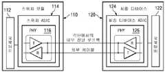
도면을 참조하면, 도 1a 내지 도 1c는 예시적인 일 실시예에 따른 저장 네트워크의 내로우 포트의 블록도이다. 구체적으로 도 1a를 참조하면, 스위치 모듈(110)은 프로세서(112) 및 스위치 주문형 반도체(ASIC; 114)를 포함한다. 스위치 ASIC(114)은 물리적 송수신기 소자(PHY; 116)를 구비한다. PHY는 송신기와 수신기 쌍을 포함한다. 각 디바이스(120)는 프로세서(122)와 최종 디바이스 ASIC(124)을 구비한다. 최종 디바이스 ASIC(124)은 PHY(126)을 구비한다. PHY(126)는 정상 데이터 이송을 위한 외부 케이블을 통해 PHY(126)에 접속된다. 예시적인 일 실시예에서, 스위치 모듈(110)은 직렬 부착형 SCSI(SAS) 스위치 모듈일 수 있으며, 최종 디바이스(120)는 SAS 최종 디바이스일 수 있다.1A-1C are block diagrams of narrow ports of a storage network according to one exemplary embodiment. Specifically, referring to FIG. 1A, the
이하 도 1b를 참조하면, 스위치 ASIC(114)의 PHY(116) 및 최종 디바이스 ASIC(124)의 PHY(126)는 각 단에서 내부 진단 루프백을 위해 구성된다. 예시적인 일 실시예에 따르면, PHY(116)와 PHY(126)는 내부 루프백을 형성하도록 송신기를 수신기에 접속하는 능력을 갖는다. 도 1b는 외부 인터페이스의 진단 검증 동안 SAS 네트워크가 어떻게 구성되는지를 도시한다. 케이블 연결형 인터페이스의 각 단에서의 SAS 디바이스들은 각 디바이스의 내로우 포트를 실제로 검사하도록 내부 래핑을 수행한다.1B, the
도 1c를 참조하면, 최종 디바이스 ASIC(124)의 PHY(126)는 최종 디바이스에서 진단 루프백을 위해 구성된다. PHY(126)는 외부 루프백을 형성하도록 송신기를 수신기에 접속하는 능력을 갖는다. 도 1c는 더 상세히 후술할 내로우 포트에 대한 프로시저 및 케이블 길이 검출 메커니즘의 기본을 제공하는 구성을 도시한다.1C, the
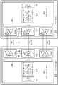
도 2a 내지 도 2c는 예시적인 일 실시예에 따른 저장 네트워크의 와이드 포트의 블록도이다. 구체적으로 도 2a를 참조하면, 스위치 모듈(210)은, 스위치 프로세서(222), 데이터 프로세서(224), 스위치(226), PHY 0-N(212 내지 216)을 구비하는 스위치 ASIC(220)을 포함한다. 각 PHY는 송신기와 수신기 쌍을 포함한다. 데이터 프로세서(224)는 순환 중복 검사 모듈, 패턴 생성기/검사 모듈, 데이터 버퍼, 패킷 컨트롤러, 또는 프로토콜 컨트롤러 중 적어도 하나를 포함한다. 최종 디바이스(230)는, 타겟 프로세서(242), 데이터 프로세서(244), 스위치(246), PHY 0-N(232 내지 236)을 구비하는 최종 디바이스 ASIC(240)을 포함한다. PHY(212 내지 2l6)는 정상 데이터 이송을 위한 와이드 포트 외부 케이블을 통해 PHY(232 내지 236)에 각각 접속된다. 예시적인 일 실시예에서, 스위치 모듈(210)은 직렬 부착형 SCSI(SAS) 스위치 모듈일 수 있으며, 최종 디바이스(230)는 SAS 최종 디바이스일 수 있다.2A-2C are block diagrams of wide ports of a storage network, according to one exemplary embodiment. Specifically, referring to FIG. 2A, the
이하 도 2b를 참조하면, 스위치 ASIC(220)의 PHY(212 내지 216) 및 최종 디바이스 ASIC(240)의 PHY(232 내지 236)는 각 단에서 내부 진단 루프백을 위해 구성된다. 예시적인 일 실시예에 따르면, PHY(212 내지 216)와 PHY(232 내지 236)는 내부 루프백을 형성하도록 송신기를 수신기에 접속하는 능력을 갖는다. 도 2b는 외부 인터페이스의 진단 검증 동안 와이드 포트 SAS 네트워크가 어떻게 구성되는지를 도시한다. 케이블 연결형 인터페이스의 각 단에서의 SAS 장치들은 각 장치의 내로우 포트를 실제로 검사하도록 내부 래핑을 수행한다.2B, the PHYs 212-216 of the
도 2c를 참조하면, 스위치 ASIC(220)의 PHY(212) 및 최종 디바이스 ASIC(24O)의 PHY(232)는 정상 데이터 이송을 위해 구성된다. 도시한 예에서, PHY 0(212)은 커맨드 PHY이다. 최종 디바이스 ASIC(240)의 PHY 1-N(234 내지 236)은 최종 디바이스에서의 진단 루프백을 위해 구성된다. 도 2c는 더 상세히 후술할 예시적인 실시예들의 와이드 포트에 대한 프로시저 및 케이블 길이 검출 메커니즘에 대한 기본을 제공하는 구성을 도시한다.2C,
당업자라면 도 1a 내지 도 1c 및 도 2a 내지 도 2c에 도시한 하드웨어가 가변될 수 있다는 점을 인식할 것이다. 예를 들어, 도 1a 내지 도 1c의 스위치 모듈(110)은 하나보다 많은 내로우 포트들을 포함할 수 있으며, 도 2a 내지 도 2c의 스위치 모듈(210)은 하나보다 많은 와이드 포트들을 포함할 수 있다. 당업자에게 자명하듯이 저장 영역 네트워크 구성에 대하여 다른 수정을 행해도 된다.Those skilled in the art will appreciate that the hardware shown in FIGS. 1A-1C and 2A-2C may vary. For example, the
예시적인 일 실시예에 따르면, 와이드 포트를 갖는 저장 서브시스템에서 케이블 길이를 검출하기 위한 메커니즘과 프로시저를 제공한다. 이 메커니즘은 서로 다른 케이블 길이들을 결정하는 데 현장 양방향 케이블 래핑(in-situ bidirectional cable wrapping)을 이용할 수 있다. 고속 차분 인터페이스는, 일반적으로 수신기 등화뿐만 아니라 송신기 진폭도 조절할 수 있는 직렬 변환기/직병렬 변환기(SERDES) 회로라고도 알려져 있는 송신기와 수신기 회로를 구현한다는 점에 주목한다. 송신기 진폭과 수신기 등화를 조절하기 위한 메커니즘과 프로시저에 대해서는 이하 도 4 내지 도 8을 참조하여 더 상세히 설명한다. 정상 동작 동안, 가장 강건한(robust) 시스템 전기 성능을 제공하도록 이러한 매개변수들을 최적으로 조절하는 것이 바람직하다.According to one exemplary embodiment, a mechanism and procedure are provided for detecting cable length in a storage subsystem having a wide port. This mechanism can use in-situ bidirectional cable wrapping to determine different cable lengths. Note that the fast differential interface implements transmitter and receiver circuits, also known as serial converter / serial converter (SERDES) circuits, which can generally adjust the transmitter amplitude as well as receiver equalization. Mechanisms and procedures for adjusting transmitter amplitude and receiver equalization are described in greater detail below with reference to FIGS. During normal operation, it is desirable to optimally adjust these parameters to provide the most robust system electrical performance.
임의의 부착된 케이블의 길이를 결정하기 위해서는, 각 외부 포트 그리고 심지어 와이드 포트 내의 각 PHY에 대하여, 송신기 출력의 마진을 저감시키고 인터페이스에 장애가 발생하는 점까지 수신기 입력을 역조절(detune)하는 진단 프로시저를 규정한다. 성공적인 래핑으로부터 장애 발생 래핑으로의 전이점에 기초하여, 케이블 길이를 결정할 수 있다. 이는, 긴 케이블 및 짧은 케이블과 같이 소정의 케이블 길이의 수가 고정되어 있다고 가정한다. 전이점은 케이블이 긴지 또는 짧은지를 식별할 수 있으며, 이에 따라 이러한 전이점에서 정상 동작 동안 최적의 조절 매개변수를 결정하고 프로그래밍할 수 있다.To determine the length of any attached cable, for each external port and even for each PHY within the wide port, a diagnostic program that reduces the margin of the transmitter output and detunes the receiver input to the point of failure of the interface. Define the procedure. Based on the transition point from successful wrapping to failing wrapping, the cable length can be determined. This assumes that a certain number of cable lengths, such as long cables and short cables, are fixed. The transition point can identify whether the cable is long or short, thereby determining and programming the optimal regulation parameters during normal operation at this transition point.
도 3은 예시적인 일 실시예에 따라 와이드 포트를 갖는 저장 서브시스템에서 케이블 길이를 검출하기 위한 메커니즘의 동작을 도시하는 흐름도이다. 도시된 흐름도의 각 블록 및 흐름도의 블록들의 조합은 컴퓨터 프로그램 명령어에 의해 구현될 수 있다는 점을 이해할 것이다. 이러한 컴퓨터 프로그램 명령어는, 프로세서나 기타 프로그래밍 가능 데이터 처리 장치 상에서 실행되는 그 명령어가 흐름도 블록 또는 블록들에서 특정된 기능을 구현하기 위한 수단을 생성하도록, 기계를 진행시키는 프로세서나 기타 프로그래밍 가능 데이터 처리 장치에 제공될 수 있다. 또한, 프로세서나 기타 프로그래밍 가능 데이터 처리 장치가 특정한 방식으로 기능할 수 있게 하는 이러한 컴퓨터 프로그램 명령어는, 컴퓨터 판독가능 메모리 또는 저장 매체에 저장된 명령어가 흐름도 블록 또는 블록들에서 특정된 기능을 구현하는 명령어 수단을 포함하는 제조 물품을 생성하도록, 그 컴퓨터 판독가능 메모리 또는 저장 매체에 저장될 수 있다.3 is a flow diagram illustrating operation of a mechanism for detecting cable length in a storage subsystem having a wide port according to one exemplary embodiment. It will be appreciated that each block in the illustrated flow chart and combination of blocks in the flow chart can be implemented by computer program instructions. Such computer program instructions may comprise a processor or other programmable data processing device that advances a machine such that the instructions executed on the processor or other programmable data processing device generate means for implementing a function specified in the flowchart block or blocks. Can be provided. In addition, such computer program instructions that enable a processor or other programmable data processing device to function in a particular manner include instructions that implement instructions that are stored in a computer readable memory or storage medium to specify the functionality specified in the flowchart block or blocks. And may be stored in a computer readable memory or storage medium to produce an article of manufacture comprising a.
이에 따라, 도시된 흐름도의 블록들은, 특정된 기능들을 수행하기 위한 수단의 조합, 특정된 기능들을 수행하기 위한 단계들의 조합, 및 특정된 기능들을 수행하기 위한 프로그램 명령어 수단을 지원한다. 또한, 도시된 흐름도의 각 블록 및 도시된 흐름도의 블록들의 조합이 특정된 기능들이나 단계들을 수행하는 전용 하드웨어 기반 컴퓨터 시스템에 의해 또는 전용 하드웨어와 컴퓨터 명령어의 조합에 의해 구현될 수 있다는 점을 이해할 것이다.Accordingly, the blocks of the illustrated flow chart support a combination of means for performing specified functions, a combination of steps for performing specified functions, and program instruction means for performing specified functions. In addition, it will be understood that each block of the illustrated flowcharts and combinations of blocks of the illustrated flowcharts may be implemented by a dedicated hardware-based computer system that performs specified functions or steps, or by a combination of dedicated hardware and computer instructions. .
또한, 흐름도는 예시적인 실시예에서 수행되는 동작을 예시하도록 제공된다. 흐름도는 특정 동작, 또는 보다 구체적으로, 동작들의 순서에 관한 한정 사항을 설명하거나 암시하려는 것이 아니다. 흐름도의 동작들은 특정 구현예에 맞도록 수정될 수 있다.Moreover, flowcharts are provided to illustrate the operations performed in the example embodiments. The flowchart is not intended to describe or imply any particular action, or more specifically, a limitation regarding the order of the actions. The operations of the flowcharts can be modified to suit a particular implementation.
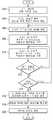
이하, 도 3을 참조하면, 와이드 포트에 접속된 케이블 길이가 미지인 경우에 동작이 시작된다. 메커니즘은, 케이블 길이 검출을 위해 각 단 상에 PHY를 구성하도록 진단 케이블 래핑 루틴을 호출한다(블록 302). 이어서, 메커니즘은 와이드 포트를 통한 통신을 위한 커맨드 PHY를 확립한다(블록 304).Referring now to Figure 3, the operation is started when the cable length connected to the wide port is unknown. The mechanism invokes a diagnostic cable wrapping routine to configure the PHY on each end for cable length detection (block 302). The mechanism then establishes a command PHY for communication over the wide port (block 304).
메커니즘은 송신기를 수신기에 접속하여 외부 루프백을 형성하도록 PHY를 구성함으로써 와이드 포트에서 다음 PHY를 래핑한다(블록 306). 메커니즘은 송신기와 수신기 매개변수들을 최소값으로 조절하고 에러율을 기록한다(블록 308). 이어서, 메커니즘은 송신기와 수신기 매개변수들을 다음 단계로 조절하고 에러율을 기록한다(블록 310). 메커니즘은 모든 조절이 완료되었는지를 결정한다(블록 312). 모든 조절이 완료되지 않았으면, 동작은 블록 310으로 복귀하여 송신기와 수신기 매개변수들을 다음 단계로 조절하고 에러율을 기록한다.The mechanism wraps the next PHY at the wide port by configuring the PHY to connect the transmitter to the receiver to form an outer loopback (block 306). The mechanism adjusts the transmitter and receiver parameters to minimum values and records the error rate (block 308). The mechanism then adjusts the transmitter and receiver parameters to the next level and records the error rate (block 310). The mechanism determines whether all adjustments have been completed (block 312). If all adjustments have not been made, operation returns to block 310 to adjust the transmitter and receiver parameters to the next level and record the error rate.
블록 312에서 PHY에 대하여 모든 조절이 완료되었다면, 메커니즘은 최종 PHY를 검사하였는지를 결정한다(블록 314). 최종 PHY가 검사되지 않았다면, 동작은 블록 306으로 복귀하여 와이드 포트에서 다음 PHY를 래핑한다.If all adjustments have been made to the PHY at
그러나, 블록 314에서 최종 PHY가 검사되었다면, 메커니즘은 각 PHY메 대한 기록된 데이터를 비교하여 값들의 테이블을 결정한다(블록 316). 메커니즘은 래핑된 PHY들에 대한 데이터를 평균화한다(블록 318). 이어서, 메커니즘은 래핑된 PHY들에 대한 평균에 기초하여 케이블 길이를 결정한다(블록 320). 이후, 동작이 종료된다.However, if the last PHY was checked at
제품 검사 동안, 다수의 케이블 길이를 부착할 수 있고, 이에 의해 장애 발생 때까지 래핑을 역조절하면서 데이터 점들(data point)의 세트를 수집함으로써 각 특정 케이블 길이를 특성화한다. 도 3은 특성 데이터가 최적의 성능 및 장애에 대하여 데이터 점들의 범위를 어떻게 반영하는지를 도시한다. 래핑 검사 동안 이러한 특성값들의 테이블을 이용하여 긴 케이블, 짧은 케이블, 또는 다른 소정의 길이의 케이블이 부착되는지를 식별할 수 있다. 다시 말하면, 알려져 있는 길이들에 대한 에러율들을 기록할 수 있다. 이어서, 메커니즘은 블록 308로부터의 기록된 값들 또는 블록 319로부터의 평균 데이터를 알려져 있는 길이들에 대하여 기록된 에러율들과 비교한다. 와이드 포트를 특성화할 때, 검사받는 다수의 링크 래핑이 존재한다. 이는 부착된 케이블의 길이를 보다 세밀하게 결정하는 데 다수의 데이터 점들을 제공한다. 도 3의 흐름도는 내로우 포트 케이블에 대한 단일 PHY에 대하여 동작할 수 있다는 점에 주목한다.During product inspection, a number of cable lengths can be attached, thereby characterizing each particular cable length by collecting a set of data points while countering the wrapping until failure occurs. 3 shows how feature data reflects a range of data points for optimal performance and impairment. The table of these characteristic values can be used during the wrapping test to identify whether a long cable, short cable, or other predetermined length of cable is attached. In other words, error rates for known lengths can be recorded. The mechanism then compares the recorded values from
예시적인 일 실시예에 따르면, 고주파 애플리케이션에 사용되는 고속 직렬 인터페이스는, 최적의 성능 설정을 결정하도록, 정상 한계값을 벗어나 마진을 동적으로 가질 수 있다. 획득된 설정은 각 물리적 경로에 대한 시스템 교정점을 나타낸다. 각 시스템은 직렬 인터페이스 접속의 각 점대점 노드에 대한 교정 데이터를 저장할 수 있다.According to one exemplary embodiment, a high speed serial interface used for high frequency applications may dynamically have margins outside the normal limits to determine optimal performance settings. The settings obtained represent the system calibration points for each physical path. Each system can store calibration data for each point-to-point node of a serial interface connection.
고속 차분 인터페이스는 네 개의 와이어로 구성될 수 있다. 두 개의 와이어는 송신 신호와 같은 단일 신호를 나타내도록 차분 사용된다. 마찬가지로, 두 개의 와이어는 수신 신호와 같은 제2 신호를 나타내도록 차분 사용된다. 이러한 방식으로, 송신 신호와 수신 신호가 구현된다. 예시적인 일 실시예에 따르면, 고속 인터페이스를 통해 서브시스템들 간의 데이터 송신의 성능을 최적화하는 메커니즘을 제공한다.The high speed differential interface may consist of four wires. Two wires are differentially used to represent a single signal, such as a transmission signal. Similarly, two wires are differentially used to represent a second signal, such as a received signal. In this way, the transmission signal and the reception signal are implemented. According to one exemplary embodiment, a mechanism is provided to optimize the performance of data transmission between subsystems over a high speed interface.
메커니즘은 통신 인터페이스 이송 기능에 스트레스를 가하는 방식으로 자극 및 응답 메커니즘의 매개변수들을 가변할 수 있다. 이어서, 메커니즘은 검사받는 특정 하드웨어의 설계/보호 대역 마진을 결정할 수 있다. 이어서, 그 결과로 발생하는 정보는 특정 하드웨어 구성에 대한 교정 인자로서 사용될 수 있다.The mechanism can vary the parameters of the stimulus and response mechanisms in a way that stresses the communication interface transfer function. The mechanism can then determine the design / guard band margin of the particular hardware being inspected. The resulting information can then be used as a calibration factor for a particular hardware configuration.
고속 SAS 스위치에 대해서는, 메커니즘은 마진을 검사하도록 전치 강조/입력 보상을 이용할 수 있다. 이 경우, 통신 인터페이스, 송신기로부터 수신기로의 점대점 통신에 중점을 둔다. 이는, 예를 들어, 블레이드 슬롯, 내부 고속 패브릭, 및 외부 케이블링을 커버할 수 있다.For high speed SAS switches, the mechanism may use pre-emphasis / input compensation to check the margin. In this case, the emphasis is on the communication interface, point-to-point communication from the transmitter to the receiver. This may, for example, cover blade slots, inner high speed fabrics, and outer cabling.
과거에는, 케이블 길이들의 한정된 세트에 대하여 또는 시스템에 대하여 단일 교정 인자를 이용하였다. 예시적인 실시예의 메커니즘은, 개별적인 점대점 교정의 결과, 케이블 길이와 경로의 수(폭이 가변적인 케이블들)에 제한을 두지 않는다. 예시적인 실시예의 메커니즘은 케이블 연결형 인터페이스에 대조되는 내부 고속 패브릭에 적용되어도 된다는 점에 주목한다. 매개변수들의 공칭 세트 대신에, 매 경로에 대하여 시스템을 최적화할 수 있다. 종종, 케이블이나 경로의 전기적 길이는, 접속에 걸친 기생 성분으로 인해 물리적 길이에 상관하지 않을 수 있다. 이러한 교정 메커니즘은 물리적 차와 전기적 차 둘 다에 대하여 시스템을 최적화할 수 있다.In the past, a single calibration factor has been used for a limited set of cable lengths or for the system. The mechanism of the exemplary embodiment does not limit the cable length and the number of paths (variable cables) as a result of individual point-to-point calibration. Note that the mechanism of the exemplary embodiment may be applied to an internal high speed fabric as opposed to a cabled interface. Instead of a nominal set of parameters, the system can be optimized for every path. Often, the electrical length of a cable or path may not be correlated to the physical length due to parasitic components across the connection. This calibration mechanism can optimize the system for both physical and electrical differences.
교정은 함께 케이블 연결된 서브시스템들의 고정된 세트와 같은 각 점대점 접속부에 대하여 적용될 수 있다. 다른 예로, 교정은 시스템 재구성, 케이블 연결 서브시스템들의 추가 또는 감소, 또는 시간이나 환경으로 인한 서브시스템 저하와 같은 서브시스템들의 변경 세트에 적용될 수 있다. 성능 교정은, 전원 공급 리셋(power on reset), 하드웨어 변경이나 재구성의 통지, 또는 설정된 한계값을 초과하여 증가된 에러 정정율에 의해 개시될 수 있다.Calibration can be applied for each point-to-point connection, such as a fixed set of subsystems cabled together. As another example, calibration may be applied to a modified set of subsystems such as system reconfiguration, addition or reduction of cabling subsystems, or subsystem degradation due to time or environment. Performance calibration can be initiated by a power on reset, notification of a hardware change or reconfiguration, or an error correction rate increased beyond a set threshold.
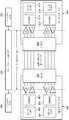
도 4는 예시적인 실시예의 양태가 구현될 수 있는 시스템 환경의 일례를 도시하는 블록도이다. 고속 서브시스템(410)은 서브시스템 외부 케이블링을 통해 고속 서브시스템(430)에 접속된다. 고속 서브시스템(410)은, 직렬 변환기/직병렬 변환기(SERDES) 회로(416)를 통해 송신기/수신기 쌍에 접속되는 PHY와 링크층들(412)을 포함한다. 또한, 고속 서브시스템(410)은, 직렬 변환기/직병렬 변환기(SERDES) 회로(418)를 통해 송신기/수신기 쌍에 접속되는 PHY와 링크층들(414)을 포함한다. 송신기/수신기 쌍은 커넥터(420)를 통해 서브시스템 외부 케이블링에 접속된다. 고속 서브시스템(430)은, 직렬 변환기/직병렬 변환기(SERDES) 회로(436)를 통해 송신기/수신기 쌍에 접속되는 PHY와 링크층들(432)을 포함한다. 또한, 고속 서브시스템(43O)은, 직렬 변환기/직병렬 변환기(SERDES) 회로(438)를 통해 송신기/수신기 쌍에 접속되는 PHY와 링크층들(434)을 포함한다. 고속 서브시스템(430)의 송신기/수신기 쌍은 커넥터(440)를 통해 서브시스템 외부 케이블링에 접속된다.4 is a block diagram illustrating an example of a system environment in which aspects of an example embodiment may be implemented. The
도 4에 도시한 예에서, 고속 서브시스템(410)에서의 PHY와 링크층들(412, 414) 및 SERDES 회로들(416, 418)은 자극(송신기)(452)을 나타낸다. 고속 서브시스템(430)에서의 PHY와 링크층들(432, 434) 및 SERDES 회로들(436, 438)은 응답(수신기)(456)을 나타낸다. 송수신기 쌍들, 커넥터들(420, 440), 및 서브시스템 외부 케이블링은 복합 인터페이스 이송 기능(454)을 나타낸다. 예시적인 실시예에 따르면, 메커니즘은 자극 및 응답 매개변수들을 가변한다. 기능성의 범위는 외부적으로 케이블 연결된 서브시스템들의 소정의 세트에 대한 성능 마진을 결정한다.In the example shown in FIG. 4, the PHY and link
도 5는 예시적인 실시예의 양태가 구현될 수 있는 서브시스템 인터페이스 환경을 도시하는 블록도이다. 호스트 시스템(510)은 내부 포트에서 SAS 스위치(518)에 접속되는 내부 애플리케이션 프로세서들(512 내지 516)을 포함한다. 저장 서브시스템들(522 내지 526)은 외부 포트에서 고속 SAS 케이블을 통해 SAS 스위치(518)에 접속된다. 예시적인 실시예의 메커니즘은 최적의 성능 설정을 찾도록 각 점대점 접속에 마진을 부여할 수 있다. 이어서, 메커니즘은 각 점대점 접속에 대하여 저장된 데이터를 교정할 수 있다.5 is a block diagram illustrating a subsystem interface environment in which aspects of an example embodiment may be implemented.
도 6은 예시적인 일 실시예에 따른 고속 점대점 교정 프로시저를 도시하는 블록도이다. 서브시스템(610)은 SERDES(616)를 통해 송신기/수신기 쌍에 접속되는 PHY와 링크층들(612)을 포함한다. 서브시스템(630)은 SERDES(636)를 통해 송신기/수신기 쌍에 접속되는 PHY와 링크층들(632)을 포함한다. 서브시스템(610)의 송신기/수신기 쌍은 외부 케이블(650)에 의해 서브시스템(630)의 송신기/수신기 쌍에 접속된다.Fig. 6 is a block diagram illustrating a fast point-to-point calibration procedure according to an exemplary embodiment.
점대점 접속부는 출력 송신기, 인쇄 회로 보드 경로, 커넥터, 내부 고속 패브릭, 외부 케이블, 및 입력 수신기를 포함한다. 예시적인 실시예의 교정 메커니즘은 송신기 및 수신기 매개변수들을 공칭 설계값으로 설정한다.Point-to-point connections include an output transmitter, a printed circuit board path, a connector, an internal high speed fabric, an external cable, and an input receiver. The calibration mechanism of the exemplary embodiment sets transmitter and receiver parameters to nominal design values.
이어서, 메커니즘은 점대점 외부 접속부의 일단(노드 A)에 대한 송신 설정점을 결정한다. 메커니즘은, 소스 스위치에서 자체 검사 패턴을 생성하고 외부 접속부의 타단(노드 B)의 수신 스위치에서의 예상 데이터를 감시한다. 메커니즘이 측정하는 매개변수는 비트 에러율(BER)이다. 예시적인 일 실시예에서, BER의 단위는 수신되는 데이터의 메가비트당 하나의 에러이다. 이어서, 교정 메커니즘은 송신 설정에 최소값(min) 내지 최대값(max) 범위 내의 마진을 부여한다. 노드 A에 대한 송신 설정점은, 노드 B인 수신기에서의 가장 높은 BER을 달성한 송신 설정점에 대응한다.The mechanism then determines a transmission set point for one end (node A) of the point-to-point external connection. The mechanism generates a self test pattern at the source switch and monitors the expected data at the receive switch at the other end of the external connection (node B). The parameter measured by the mechanism is the bit error rate (BER). In one exemplary embodiment, the unit of BER is one error per megabit of data received. The calibration mechanism then imparts a margin in the range of minimum (min) to maximum (max) to the transmission settings. The transmission set point for node A corresponds to the transmission set point that achieved the highest BER at the receiver that is node B.
이어서, 교정 메커니즘은, 점대점 외부 접속부의 타단(노드 B)에 대한 수신기 설정점을 결정한다. 메커니즘은, 소스 스위치에서 자체 검사 패턴을 생성하고 외부 접속부의 노드 B인 수신 스위치에서의 예상 데이터를 감시한다. 교정 메커니즘은 수신기 설정에 최소값(min)으로부터 최대값(max)으로의 범위의 마진을 부여한다. 노드 B의 수신기 설정점은 수신기에서 가장 높은 BER을 달성한 수신기 설정점에 대응한다.The calibration mechanism then determines the receiver set point for the other end (node B) of the point-to-point external connection. The mechanism generates a self test pattern at the source switch and monitors the expected data at the receive switch, Node B of the external connection. The calibration mechanism gives the receiver settings a margin in the range from minimum (min) to maximum (max). The receiver set point of node B corresponds to the receiver set point which achieved the highest BER at the receiver.
이어서, 교정 메커니즘은 외부 케이블 노드 C와 노드 D에 대하여 전술한 교정 시퀀스를 반복한다.The calibration mechanism then repeats the calibration sequence described above for external cable nodes C and D.
도 7은 예시적인 일 실시예에 따른 점대점 교정 메커니즘의 동작을 도시하는 흐름도이다. 동작이 시작되고, 교정 메커니즘은 송신측에서 자체 검사 패턴을 설정한다(블록 702). 교정 메커니즘은 송신 SAS 매개변수를 최소값으로 설정하고(블록 704) 수신 SAS 매개변수를 공칭값으로 설정한다(블록 706).7 is a flowchart illustrating operation of a point-to-point calibration mechanism, according to an exemplary embodiment. Operation begins, and the calibration mechanism sets up a self test pattern at the transmitting side (block 702). The calibration mechanism sets the sending SAS parameter to a minimum value (block 704) and sets the receiving SAS parameter to a nominal value (block 706).
교정 메커니즘은 비트 에러율(BER)을 계산한다(블록 708). 이어서, 메커니즘은 송신 매개변수가 최대값과 같은지를 결정한다(블록 710). 송신 매개변수가 최대값과 같지 않으면, 교정 메커니즘은 송신 SAS 매개변수를 증분하고(블록 712), 동작은 블록 708로 복귀하여 증분된 송신 매개변수에 대한 BER을 계산한다. 교정 메커니즘이 송신 SAS 매개변수에 마진을 최소값으로부터 최대값으로 부여함에 따라, 블록 714에서 알 수 있듯이, 메커니즘은 각 매개변수 값에 대하여 BER을 로깅한다.The calibration mechanism calculates the bit error rate (BER) (block 708). The mechanism then determines whether the transmission parameter is equal to the maximum value (block 710). If the transmission parameter is not equal to the maximum value, the calibration mechanism increments the transmission SAS parameter (block 712), and operation returns to block 708 to calculate the BER for the incremented transmission parameter. As the calibration mechanism imposes a margin from the minimum value to the maximum value of the sending SAS parameter, as shown in
블록 710에서 송신 매개변수가 최대값과 같으면, 교정 메커니즘은 송신 계산값을 계산한다(블록 716). 다음으로, 교정 메커니즘은 수신 SAS 매개변수를 최소값으로 설정하고(블록 718) 송신 SAS 매개변수를 공칭값으로 설정한다(블록 720).If in block 710 the transmission parameter is equal to the maximum value, then the calibration mechanism calculates the transmission calculation (block 716). The calibration mechanism then sets the receiving SAS parameter to a minimum value (block 718) and the sending SAS parameter to a nominal value (block 720).
교정 메커니즘은 BER을 계산한다(블록 722). 이어서, 메커니즘은 수신 매개변수가 최대값과 같은지를 결정한다(블록 724). 수신 매개변수가 최대값과 같지 않으면, 교정 메커니즘은 수신 SAS 매개변수를 증분하고(블록 726), 동작은 블록 722로 복귀하여 증분된 수신 매개변수에 대한 BER을 계산한다. 교정 메커니즘이 수신 SAS 매개변수에 마진을 최소값으로부터 최대값으로 부여함에 따라, 블록 728에서 알 수 있듯이, 메커니즘은 각 매개변수 값에 대하여 BER을 로깅한다.The calibration mechanism calculates the BER (block 722). The mechanism then determines whether the received parameter is equal to the maximum (block 724). If the receive parameter is not equal to the maximum value, the calibration mechanism increments the receive SAS parameter (block 726), and operation returns to block 722 to calculate the BER for the incremented receive parameter. As the calibration mechanism imposes a margin from the minimum value to the maximum value of the received SAS parameter, as shown in
블록 724에서 수신 매개변수가 최대값과 같으면, 교정 메커니즘은 수신 교정값을 계산한다(블록 730). 이후, 동작이 종료된다.If the receive parameter in block 724 is equal to the maximum value, then the calibration mechanism calculates the received calibration value (block 730). Thereafter, the operation ends.
도 8은 예시적인 일 실시예에 따른 시스템 교정을 도시하는 흐름도이다. 동작은, 전원 공급 리셋(블록 802), 시스템 재구성(블록 804), 케이블 연결형 서브시스템들의 추가 또는 감소(블록 806), 또는 SAS 비트 에러율 인터페이스 저하(블록 808)를 포함하는 복수의 개시 조건 중 하나에 응답하여 시작된다. 교정 메커니즘은, 개시 조건에 응답하여, 영향을 받은 고속 인터페이스에 대하여 점대점 교정을 수행한다(블록 810). 이어서, 교정 메커니즘은 시스템 펌웨어에 있는 교정 매개변수를 갱신한다(블록 812). 이후, 시스템 교정이 완료되고(블록 814), 동작이 종료된다.8 is a flow diagram illustrating system calibration according to an exemplary embodiment. The operation may be one of a plurality of initiation conditions including a power supply reset (block 802), system reconfiguration (block 804), addition or reduction of cabled subsystems (block 806), or SAS bit error rate interface degradation (block 808). Starts in response. The calibration mechanism, in response to the initiation condition, performs point-to-point calibration on the affected high speed interface (block 810). The calibration mechanism then updates the calibration parameters in the system firmware (block 812). Thereafter, system calibration is complete (block 814), and the operation ends.
따라서, 예시적인 실시예들은, 와이드 포트를 갖는 저장 서브시스템에서 케이블 길이를 검출하는 메커니즘과 프로시저를 제공함으로써, 종래 기술의 단점을 해결한다. 메커니즘은 서로 다른 케이블 길이들을 결정하는 데 현장 양방향 케이블 래핑을 이용할 수 있다. 메커니즘은 각 외부 포트에 대하여 그리고 심지어 와이드 포트 내의 각 PHY에 대하여 장애로 되는 송신기 출력에 마진을 작게 부여한다. 양호한 래핑으로부터 불량한 래핑으로의 전이점에 기초하여, 케이블 길이를 결정할 수 있다. 이는, 소정의 케이블 길이의 수가 긴 것과 짧은 것과 같이 고정되어 있다고 가정한다. 전이점은 케이블이 긴지 짧은지를 식별하며, 이에 따라 이러한 전이점에서 최적의 조절 매개변수를 설정할 수 있다.Accordingly, exemplary embodiments solve the disadvantages of the prior art by providing a mechanism and procedure for detecting cable length in a storage subsystem having a wide port. The mechanism can use field bidirectional cable wrapping to determine different cable lengths. The mechanism places a small margin on the failing transmitter output for each external port and even for each PHY in the wide port. Based on the transition point from good wrapping to poor wrapping, the cable length can be determined. This assumes that the number of predetermined cable lengths is fixed as long and short. The transition point identifies whether the cable is long or short, so that optimal adjustment parameters can be set at this transition point.
예시적인 실시예들은 고속 송신기/수신기 쌍 특성을 교정하고 이에 따라 서브시스템들 간의 송신 성능을 최적화하는 메커니즘을 더 제공한다. 메커니즘은 에러 정정을 빈번하게 행할 필요를 줄이고 에러 정정 기술에 연관된 성능 저하를 야기하지 않는다.Exemplary embodiments further provide a mechanism for calibrating high speed transmitter / receiver pair characteristics and thus optimizing transmission performance between subsystems. The mechanism reduces the need for frequent error correction and does not cause performance degradation associated with error correction techniques.
예시적인 실시예들은 완전히 하드웨어인 실시예, 완전히 소프트웨어인 실시예, 또는 하드웨어와 소프트웨어 요소들을 포함하는 실시예의 형태를 취할 수 있다는 점을 인식하기 바란다. 예시적인 일 실시예에서, 예시적인 실시예의 메커니즘은, 펌웨어, 상주 소프트웨어, 마이크로 코드 등을 포함하는 소프트웨어로 구현되지만, 이러한 예로 한정되지는 않는다.It should be appreciated that the example embodiments may take the form of an entirely hardware embodiment, an entirely software embodiment, or an embodiment that includes hardware and software elements. In one example embodiment, the mechanisms of the example embodiments are implemented in software, including but not limited to firmware, resident software, microcode, and the like.
또한, 예시적인 실시예들은, 컴퓨터 또는 임의의 명령적 실행 시스템에 의해 또는 이러한 컴퓨터 또는 임의의 명령어 실행 시스템과 함께 사용되는 프로그램 코드를 제공하는 컴퓨터 이용가능 매체나 컴퓨터 판독가능 매체로부터 액세스가능한 컴퓨터 프로그램 제품의 형태를 취할 수 있다. 본 발명을 설명하기 위해, 컴퓨터 이용가능 매체나 컴퓨터 판독가능 매체는, 명령어 실행 시스템, 장치나 디바이스에 의해 또는 이러한 명령어 실행 시스템, 장치나 디바이스와 함께 사용되는 프로그램을 포함하고, 저장하고, 통신하고, 전파하고, 이송할 수 있는 임의의 장치일 수 있다.Also, the exemplary embodiments may be computer programs accessible by a computer usable or computer readable medium providing program code for use by or in conjunction with a computer or any instruction execution system. It may take the form of a product. To illustrate the present invention, a computer usable medium or computer readable medium includes, stores, communicates with, and stores a program for use by or in conjunction with an instruction execution system, apparatus, or device. It may be any device capable of propagating and transporting.
이러한 매체는, 전자 매체, 자기 매체, 광학 매체, 전자기 매체, 적외선 매체, 또는 반도체 시스템(또는 장치나 디바이스) 또는 전파 매체일 수 있다. 컴퓨터 이용가능 매체의 예로는, 반도체나 고체 메모리, 자기 테이프, 착탈식 컴퓨터 디스켓, RAM, ROM, 경질의 자기 디스크, 및 광 디스크가 있다. 광 디스크의 최근 예로는 CD-ROM, CD-R/W, 및 DVD가 있다.Such a medium may be an electronic medium, a magnetic medium, an optical medium, an electromagnetic medium, an infrared medium, or a semiconductor system (or apparatus or device) or a propagation medium. Examples of computer usable media include semiconductors or solid state memory, magnetic tapes, removable computer diskettes, RAMs, ROMs, hard magnetic disks, and optical disks. Recent examples of optical discs are CD-ROM, CD-R / W, and DVD.
프로그램 코드를 저장하고 그리고/또는 실행하는 데 적합한 데이터 처리 시스템은, 시스템 버스를 통해 메모리 소자들에 직접적으로 또는 간접적으로 연결되는 적어도 하나의 프로세서를 포함한다. 메모리 소자들은, 프로그램 코드의 실제 실행 동안 채용되는 로컬 메모리, 대용량 저장 장치, 및 실행 동안 대용량 저장 장치로부터 프로그램 코드가 검색되어야 하는 횟수를 저감시키기 위해 적어도 일부 프로그램 코드의 일시 저장부를 제공하는 캐시 메모리를 포함할 수 있다.A data processing system suitable for storing and / or executing program code includes at least one processor coupled directly or indirectly to memory elements via a system bus. The memory elements include a local memory employed during actual execution of the program code, a mass storage device, and a cache memory that provides temporary storage of at least some program code to reduce the number of times the program code should be retrieved from the mass storage device during execution. It may include.
입력/출력 또는 I/O 디바이스(키보드, 디스플레이, 포인팅 디바이스 등을 포함하지만, 이러한 예로 한정되지는 않음)는 시스템에 직접적으로 또는 I/O 컨트롤러를 개재하여 연결될 수 있다. 데이터 처리 시스템이 사설 네트워크와 공중 네트워크를 통해 다른 데이터 처리 시스템이나 원격 프린터 또는 저장 디바이스에 연결될 수 있도록 네트워크 아답터도 시스템에 연결될 수 있다. 모뎀, 케이블 모뎀, 및 이더넷 카드는 현재 이용가능한 유형의 네트워크 아답터들 중 몇 개의 예일 뿐이다.Input / output or I / O devices (including but not limited to keyboards, displays, pointing devices, etc.) may be connected directly to the system or via an I / O controller. Network adapters may also be coupled to the system such that the data processing system may be coupled to other data processing systems or remote printers or storage devices via private and public networks. Modems, cable modems, and Ethernet cards are just a few examples of network adapters of the type currently available.
Claims (10)
Translated fromKorean상기 컴퓨팅 디바이스에서의 적어도 하나의 송신기 매개변수와 적어도 하나의 수신기 매개변수를 설정하고 에러율을 기록하는 단계와,
상기 적어도 하나의 송신기 매개변수와 상기 적어도 하나의 수신기 매개변수가 최소값으로부터 최대값으로 마진을 가질 때까지 상기 적어도 하나의 송신기 매개변수와 상기 적어도 하나의 수신기 매개변수를 조절하고 상기 에러율을 기록하는 단계와,
상기 기록된 에러율들을 알려져 있는 케이블 길이에 대한 에러율들과 비교하는 단계와,
상기 비교에 기초하여 케이블 길이를 결정하는 단계
를 포함하는, 케이블 길이의 검출 방법.A method for detecting cable length in a computing device, comprising:
Setting at least one transmitter parameter and at least one receiver parameter at the computing device and recording an error rate;
Adjusting the at least one transmitter parameter and the at least one receiver parameter and recording the error rate until the at least one transmitter parameter and the at least one receiver parameter have a margin from a minimum value to a maximum value Wow,
Comparing the recorded error rates with error rates for known cable lengths;
Determining cable length based on the comparison
Comprising a cable length detection method.
진단 루프백을 위해 최종 디바이스(end device)에서의 송신기/수신기 쌍을 구성하는 단계를 더 포함하는, 케이블 길이의 검출 방법.The method of claim 1,
Configuring the transmitter / receiver pair at the end device for diagnostic loopback.
상기 컴퓨팅 디바이스는, 복수의 송신기/수신기 쌍을 포함하고, 와이드 포트 케이블에 의해 최종 디바이스에 접속되는, 케이블 길이의 검출 방법.The method according to claim 1 or 2,
And the computing device comprises a plurality of transmitter / receiver pairs and connected to the end device by a wide port cable.
상기 적어도 하나의 송신기 매개변수와 상기 적어도 하나의 수신기 매개변수를 조절하는 단계는,
복수의 송신기/수신기 쌍 내의 모든 송신기/수신기 쌍들에 대한 상기 적어도 하나의 송신기 매개변수와 상기 적어도 하나의 수신기 매개변수가 최소값으로부터 최대값으로 마진을 가질 때까지 다음 송신기/수신기 쌍에 대한 상기 적어도 하나의 송신기 매개변수와 상기 적어도 하나의 수신기 매개변수를 반복적으로 조절하는 단계를 포함하는, 케이블 길이의 검출 방법.4. The method according to any one of claims 1 to 3,
Adjusting the at least one transmitter parameter and the at least one receiver parameter,
The at least one transmitter parameter for all transmitter / receiver pairs in a plurality of transmitter / receiver pairs and the at least one for the next transmitter / receiver pair until the at least one receiver parameter has a margin from minimum to maximum Iteratively adjusting the transmitter parameters of the at least one receiver parameter.
상기 적어도 하나의 송신기 매개변수와 상기 적어도 하나의 수신기 매개변수를 반복적으로 조절하는 단계는,
송신기 매개변수를 최소값으로 설정하고, 수신기 매개변수를 공칭값으로 설정하고, 에러율을 계산하고, 상기 계산된 에러율을 로깅(log)하고, 상기 송신기 매개변수를 반복적으로 증분하고, 상기 에러율을 계산하고, 상기 송신기 매개변수가 최대값에 도달할 때까지 상기 계산된 에러율을 로깅하는 단계, 또는
송신기 매개변수를 공칭값으로 설정하고, 수신기 매개변수를 최소값으로 설정하고, 에러율을 계산하고, 상기 계산된 에러율을 로깅하고, 상기 수신기 매개변수를 반복적으로 증분하고, 상기 에러율을 계산하고, 상기 수신기 매개변수가 최대값에 도달할 때까지 상기 계산된 에러율을 로깅하는 단계 중 하나를 포함하는, 케이블 길이의 검출 방법.The method of claim 4, wherein
Repeatedly adjusting the at least one transmitter parameter and the at least one receiver parameter,
Set the transmitter parameter to a minimum value, set the receiver parameter to a nominal value, calculate the error rate, log the calculated error rate, iteratively increment the transmitter parameter, calculate the error rate, Logging the calculated error rate until the transmitter parameter reaches a maximum value, or
Set a transmitter parameter to a nominal value, set a receiver parameter to a minimum value, calculate an error rate, log the calculated error rate, iteratively increment the receiver parameter, calculate the error rate, and receive the receiver And logging one of the calculated error rates until a parameter reaches a maximum value.
프로세서를 포함하고,
상기 프로세서는, 컴퓨팅 디바이스에서의 적어도 하나의 송신기 매개변수와 적어도 하나의 수신기 매개변수를 설정하고 에러율을 기록하고, 상기 적어도 하나의 송신기 매개변수와 상기 적어도 하나의 수신기 매개변수가 최소값으로부터 최대값으로 마진을 가질 때까지 상기 적어도 하나의 송신기 매개변수와 상기 적어도 하나의 수신기 매개변수를 조절하고 상기 에러율을 기록하고, 상기 기록된 에러율들을 알려져 있는 케이블 길이에 대한 에러율들과 비교하고, 상기 비교에 기초하여 케이블 길이를 결정하도록 구성되는, 장치.At least one transmitter / receiver pair,
Includes a processor,
The processor sets at least one transmitter parameter and at least one receiver parameter at a computing device and records an error rate, wherein the at least one transmitter parameter and the at least one receiver parameter are from minimum to maximum. Adjust the at least one transmitter parameter and the at least one receiver parameter and record the error rate until it has a margin, compare the recorded error rates with error rates for known cable lengths, and based on the comparison And determine the cable length.
상기 적어도 하나의 송신기/수신기 쌍은, 복수의 송신기/수신기 쌍을 포함하고, 와이드 포트 케이블에 의해 최종 디바이스에 접속되는 스위치 모듈인, 장치.The method of claim 6,
And the at least one transmitter / receiver pair is a switch module comprising a plurality of transmitter / receiver pairs and connected to the end device by a wide port cable.
상기 적어도 하나의 송신기 매개변수와 상기 적어도 하나의 수신기 매개변수를 조절하는 것은, 복수의 송신기/수신기 쌍 내의 모든 송신기/수신기 쌍들에 대한 상기 적어도 하나의 송신기 매개변수와 상기 적어도 하나의 수신기 매개변수가 최소값으로부터 최대값으로 마진을 가질 때까지 다음 송신기/수신기 쌍에 대한 상기 적어도 하나의 송신기 매개변수와 상기 적어도 하나의 수신기 매개변수를 반복적으로 조절하는 것을 포함하는, 장치.The method according to claim 6 or 7,
Adjusting the at least one transmitter parameter and the at least one receiver parameter includes the at least one transmitter parameter and the at least one receiver parameter for all transmitter / receiver pairs in a plurality of transmitter / receiver pairs. Iteratively adjusting the at least one transmitter parameter and the at least one receiver parameter for a next transmitter / receiver pair until the margin has a margin from a minimum value to a maximum value.
상기 적어도 하나의 송신기 매개변수와 상기 적어도 하나의 수신기 매개변수를 반복적으로 조절하는 것은,
송신기 매개변수를 최소값으로 설정하고, 수신기 매개변수를 공칭값으로 설정하고, 에러율을 계산하고, 상기 계산된 에러율을 로깅하고, 상기 송신기 매개변수를 반복적으로 증분하고, 상기 에러율을 계산하고, 상기 송신기 매개변수가 최대값에 도달할 때까지 상기 계산된 에러율을 로깅하는 것, 또는
송신기 매개변수를 공칭값으로 설정하고, 수신기 매개변수를 최소값으로 설정하고, 에러율을 계산하고, 상기 계산된 에러율을 로깅하고, 상기 수신기 매개변수를 반복적으로 증분하고, 상기 에러율을 계산하고, 상기 수신기 매개변수가 최대값에 도달할 때까지 상기 계산된 에러율을 로깅하는 것
중 하나를 포함하는, 장치The method of claim 8,
Iteratively adjusting the at least one transmitter parameter and the at least one receiver parameter,
Set a transmitter parameter to a minimum value, set a receiver parameter to a nominal value, calculate an error rate, log the calculated error rate, iteratively increment the transmitter parameter, calculate the error rate, and Logging the calculated error rate until the parameter reaches a maximum value, or
Set a transmitter parameter to a nominal value, set a receiver parameter to a minimum value, calculate an error rate, log the calculated error rate, iteratively increment the receiver parameter, calculate the error rate, and receive the receiver Logging the calculated error rate until the parameter reaches its maximum value
Device, including one of
상기 기록된 에러율들을 알려져 있는 케이블 길이에 대한 에러율들과 비교하는 것은, 상기 복수의 송신기/수신기 쌍에 대한 상기 기록된 에러율들을 평균화하는 것을 포함하는, 장치.10. The method of claim 9,
Comparing the recorded error rates with error rates for known cable lengths includes averaging the recorded error rates for the plurality of transmitter / receiver pairs.
Applications Claiming Priority (2)
| Application Number | Priority Date | Filing Date | Title |
|---|---|---|---|
| US11/828,667 | 2007-07-26 | ||
| US11/828,667US7903746B2 (en) | 2007-07-26 | 2007-07-26 | Calibrating parameters in a storage subsystem with wide ports |
Publications (2)
| Publication Number | Publication Date |
|---|---|
| KR20100064357Atrue KR20100064357A (en) | 2010-06-14 |
| KR101039172B1 KR101039172B1 (en) | 2011-06-03 |
Family
ID=39967529
Family Applications (1)
| Application Number | Title | Priority Date | Filing Date |
|---|---|---|---|
| KR1020107001418AExpired - Fee RelatedKR101039172B1 (en) | 2007-07-26 | 2008-06-18 | Apparatus and Method for Detecting Cable Length in Storage Subsystems with Wide Ports |
Country Status (6)
| Country | Link |
|---|---|
| US (1) | US7903746B2 (en) |
| EP (1) | EP2183675B1 (en) |
| JP (1) | JP4571711B1 (en) |
| KR (1) | KR101039172B1 (en) |
| CN (1) | CN101802799B (en) |
| WO (1) | WO2009013081A1 (en) |
Families Citing this family (39)
| Publication number | Priority date | Publication date | Assignee | Title |
|---|---|---|---|---|
| US7983373B2 (en)* | 2007-02-07 | 2011-07-19 | Vintomie Networks B.V., Llc | Clock distribution for 10GBase-T analog front end |
| US8959307B1 (en) | 2007-11-16 | 2015-02-17 | Bitmicro Networks, Inc. | Reduced latency memory read transactions in storage devices |
| US8804710B2 (en)* | 2008-12-29 | 2014-08-12 | Juniper Networks, Inc. | System architecture for a scalable and distributed multi-stage switch fabric |
| US8804711B2 (en)* | 2008-12-29 | 2014-08-12 | Juniper Networks, Inc. | Methods and apparatus related to a modular switch architecture |
| US9225666B1 (en) | 2009-03-31 | 2015-12-29 | Juniper Networks, Inc. | Distributed multi-stage switch fabric |
| US8279863B2 (en)* | 2009-06-30 | 2012-10-02 | Juniper Networks, Inc. | Methods and apparatus for dynamic detection of transit times between stages in distributed multi-stage switch fabrics |
| US8665601B1 (en) | 2009-09-04 | 2014-03-04 | Bitmicro Networks, Inc. | Solid state drive with improved enclosure assembly |
| US8447908B2 (en) | 2009-09-07 | 2013-05-21 | Bitmicro Networks, Inc. | Multilevel memory bus system for solid-state mass storage |
| US8560804B2 (en) | 2009-09-14 | 2013-10-15 | Bitmicro Networks, Inc. | Reducing erase cycles in an electronic storage device that uses at least one erase-limited memory device |
| US8184933B1 (en) | 2009-09-22 | 2012-05-22 | Juniper Networks, Inc. | Systems and methods for identifying cable connections in a computing system |
| US8705500B1 (en) | 2009-11-05 | 2014-04-22 | Juniper Networks, Inc. | Methods and apparatus for upgrading a switch fabric |
| US8369321B2 (en) | 2010-04-01 | 2013-02-05 | Juniper Networks, Inc. | Apparatus and methods related to the packaging and cabling infrastructure of a distributed switch fabric |
| WO2012164610A1 (en) | 2011-05-31 | 2012-12-06 | Hitachi, Ltd. | Storage apparatus and method of controlling the same |
| US9372755B1 (en) | 2011-10-05 | 2016-06-21 | Bitmicro Networks, Inc. | Adaptive power cycle sequences for data recovery |
| US9043669B1 (en) | 2012-05-18 | 2015-05-26 | Bitmicro Networks, Inc. | Distributed ECC engine for storage media |
| JP6036073B2 (en) | 2012-09-19 | 2016-11-30 | 富士通株式会社 | Transmission unit, diagnostic method and diagnostic program |
| US9423457B2 (en) | 2013-03-14 | 2016-08-23 | Bitmicro Networks, Inc. | Self-test solution for delay locked loops |
| US9672178B1 (en) | 2013-03-15 | 2017-06-06 | Bitmicro Networks, Inc. | Bit-mapped DMA transfer with dependency table configured to monitor status so that a processor is not rendered as a bottleneck in a system |
| US9934045B1 (en) | 2013-03-15 | 2018-04-03 | Bitmicro Networks, Inc. | Embedded system boot from a storage device |
| US9430386B2 (en) | 2013-03-15 | 2016-08-30 | Bitmicro Networks, Inc. | Multi-leveled cache management in a hybrid storage system |
| US9858084B2 (en) | 2013-03-15 | 2018-01-02 | Bitmicro Networks, Inc. | Copying of power-on reset sequencer descriptor from nonvolatile memory to random access memory |
| US9734067B1 (en) | 2013-03-15 | 2017-08-15 | Bitmicro Networks, Inc. | Write buffering |
| US9501436B1 (en) | 2013-03-15 | 2016-11-22 | Bitmicro Networks, Inc. | Multi-level message passing descriptor |
| US9842024B1 (en) | 2013-03-15 | 2017-12-12 | Bitmicro Networks, Inc. | Flash electronic disk with RAID controller |
| US9400617B2 (en) | 2013-03-15 | 2016-07-26 | Bitmicro Networks, Inc. | Hardware-assisted DMA transfer with dependency table configured to permit-in parallel-data drain from cache without processor intervention when filled or drained |
| US9875205B1 (en) | 2013-03-15 | 2018-01-23 | Bitmicro Networks, Inc. | Network of memory systems |
| US9971524B1 (en) | 2013-03-15 | 2018-05-15 | Bitmicro Networks, Inc. | Scatter-gather approach for parallel data transfer in a mass storage system |
| US10489318B1 (en) | 2013-03-15 | 2019-11-26 | Bitmicro Networks, Inc. | Scatter-gather approach for parallel data transfer in a mass storage system |
| US9798688B1 (en) | 2013-03-15 | 2017-10-24 | Bitmicro Networks, Inc. | Bus arbitration with routing and failover mechanism |
| JP2015019163A (en)* | 2013-07-09 | 2015-01-29 | 富士通株式会社 | Control device and control method |
| US10042792B1 (en) | 2014-04-17 | 2018-08-07 | Bitmicro Networks, Inc. | Method for transferring and receiving frames across PCI express bus for SSD device |
| US10078604B1 (en) | 2014-04-17 | 2018-09-18 | Bitmicro Networks, Inc. | Interrupt coalescing |
| US9952991B1 (en) | 2014-04-17 | 2018-04-24 | Bitmicro Networks, Inc. | Systematic method on queuing of descriptors for multiple flash intelligent DMA engine operation |
| US10055150B1 (en) | 2014-04-17 | 2018-08-21 | Bitmicro Networks, Inc. | Writing volatile scattered memory metadata to flash device |
| US10025736B1 (en) | 2014-04-17 | 2018-07-17 | Bitmicro Networks, Inc. | Exchange message protocol message transmission between two devices |
| US20160315701A1 (en)* | 2015-04-24 | 2016-10-27 | Fujitsu Limited | Optical transmission device, method for verifying connection, and wavelength selective switch card |
| US10552050B1 (en) | 2017-04-07 | 2020-02-04 | Bitmicro Llc | Multi-dimensional computer storage system |
| CN109542367B (en)* | 2018-10-26 | 2022-10-21 | 森大(深圳)技术有限公司 | Rate matching method and device for printer mainboard optical fiber communication and printing system |
| US10832536B2 (en) | 2018-12-07 | 2020-11-10 | International Business Machines Corporation | Guided cable management |
Family Cites Families (23)
| Publication number | Priority date | Publication date | Assignee | Title |
|---|---|---|---|---|
| US4771230A (en) | 1986-10-02 | 1988-09-13 | Testamatic Corporation | Electro-luminescent method and testing system for unpopulated printed circuit boards, ceramic substrates, and the like having both electrical and electro-optical read-out |
| US5592077A (en) | 1995-02-13 | 1997-01-07 | Cirrus Logic, Inc. | Circuits, systems and methods for testing ASIC and RAM memory devices |
| JPH0918523A (en) | 1995-06-29 | 1997-01-17 | Fujitsu Ltd | Automatic output voltage adjustment method for transmission equipment |
| JP3446918B2 (en) | 1995-12-15 | 2003-09-16 | ソニー株式会社 | Cable length detection circuit and cable length detection method |
| US5953384A (en) | 1997-06-05 | 1999-09-14 | Motorola, Inc. | Automatic measurement of GPS cable delay time |
| US5818378A (en) | 1997-06-10 | 1998-10-06 | Advanced Micro Devices, Inc. | Cable length estimation circuit using data signal edge rate detection and analog to digital conversion |
| JP2000183938A (en) | 1998-12-15 | 2000-06-30 | Hitachi Cable Ltd | Switching hub |
| US6734681B2 (en) | 2001-08-10 | 2004-05-11 | James Sabey | Apparatus and methods for testing circuit boards |
| US20030165340A1 (en) | 2001-10-12 | 2003-09-04 | Harish Jayaram | System and method for determining a cause of electrical signal degradation based on optical signal degradation |
| US20030161630A1 (en) | 2001-10-12 | 2003-08-28 | Harish Jayaram | System and method of setting thresholds for optical performance parameters |
| US6646454B2 (en) | 2002-01-07 | 2003-11-11 | Test-Um, Inc. | Electronic apparatus and method for measuring length of a communication cable |
| US7075283B1 (en) | 2002-06-07 | 2006-07-11 | Marvell International Ltd. | Cable tester |
| US7002353B1 (en) | 2002-06-07 | 2006-02-21 | Marvell International, Ltd. | Cable tester |
| US8385188B2 (en)* | 2002-10-29 | 2013-02-26 | Broadcom Corporation | Multi-port, gigabit serdes transceiver capable of automatic fail switchover |
| CN100520418C (en)* | 2002-12-12 | 2009-07-29 | 理想工业公司 | LAN cable run test system and patch cord length measurement for LAN tester |
| EP1434414B1 (en)* | 2002-12-27 | 2013-11-20 | Koninklijke KPN N.V. | System for measuring the effect of an ADSL splitter on an ISDN network |
| US7624174B2 (en) | 2003-05-22 | 2009-11-24 | Microsoft Corporation | Self-learning method and system for detecting abnormalities |
| JP2005056179A (en)* | 2003-08-05 | 2005-03-03 | Toshiba Corp | Electronic device having serial ATA interface and signal amplitude adjusting method |
| US7135873B2 (en) | 2003-09-05 | 2006-11-14 | Psibor Date Systems, Inc. | Digital time domain reflectometer system |
| US7302379B2 (en)* | 2003-12-07 | 2007-11-27 | Adaptive Spectrum And Signal Alignment, Inc. | DSL system estimation and parameter recommendation |
| AU2006268292B2 (en)* | 2005-07-10 | 2011-03-24 | Adaptive Spectrum And Signal Alignment, Incorporated | DSL system estimation |
| US8483108B2 (en)* | 2006-07-24 | 2013-07-09 | Apple Inc. | Apparatus and methods for de-emphasis training on a point-to-point connection |
| US20080192814A1 (en)* | 2007-02-09 | 2008-08-14 | Dft Microsystems, Inc. | System and Method for Physical-Layer Testing of High-Speed Serial Links in their Mission Environments |
- 2007
- 2007-07-26USUS11/828,667patent/US7903746B2/ennot_activeExpired - Fee Related
- 2008
- 2008-06-18EPEP08761166Apatent/EP2183675B1/enactiveActive
- 2008-06-18CNCN2008800255889Apatent/CN101802799B/ennot_activeExpired - Fee Related
- 2008-06-18JPJP2010517337Apatent/JP4571711B1/ennot_activeExpired - Fee Related
- 2008-06-18KRKR1020107001418Apatent/KR101039172B1/ennot_activeExpired - Fee Related
- 2008-06-18WOPCT/EP2008/057713patent/WO2009013081A1/enactiveApplication Filing
Also Published As
| Publication number | Publication date |
|---|---|
| JP2010536194A (en) | 2010-11-25 |
| US7903746B2 (en) | 2011-03-08 |
| EP2183675B1 (en) | 2012-08-22 |
| CN101802799A (en) | 2010-08-11 |
| WO2009013081A1 (en) | 2009-01-29 |
| EP2183675A1 (en) | 2010-05-12 |
| CN101802799B (en) | 2012-07-11 |
| US20090028229A1 (en) | 2009-01-29 |
| JP4571711B1 (en) | 2010-10-27 |
| KR101039172B1 (en) | 2011-06-03 |
Similar Documents
| Publication | Publication Date | Title |
|---|---|---|
| KR101039172B1 (en) | Apparatus and Method for Detecting Cable Length in Storage Subsystems with Wide Ports | |
| US10931368B2 (en) | Method and apparatus for testing using a transceiver module | |
| EP2609697B1 (en) | Scalable high speed gigabit active bundle link and tester | |
| US7805657B2 (en) | Techniques to determine transmission quality of a signal propagation medium | |
| CN112448772B (en) | Method and device for automatically adjusting compensation parameters | |
| EP1933491A2 (en) | Serial transmission system, a method for automatically correcting signal quality of serial transmission system, and port | |
| US11228340B1 (en) | Ethernet link transmit power method based on network provided alien crosstalk feedback | |
| US7949489B2 (en) | Detecting cable length in a storage subsystem with wide ports | |
| US20100118930A1 (en) | Signal transmission apparatus and method | |
| US20110267073A1 (en) | Validating high speed link performance margin for switch fabric with any-to-any connection across a midplane | |
| US20080022022A1 (en) | Information transmission device and information transmission method | |
| US10868580B1 (en) | Ethernet link transmit power method based on alien crosstalk feedback | |
| US8483577B2 (en) | Programmable signal emphasis for optical transmitters | |
| CN112350785B (en) | Method and system for checking SERDES communication link performance | |
| CN113726425B (en) | Wired communication method, device, equipment and readable storage medium | |
| US6438159B1 (en) | Method and apparatus for margining error rate of multi-drop data buses | |
| US7979756B2 (en) | Apparatus, system and method for a go/no go link integrity tester | |
| US11901968B2 (en) | Data rate and transmit power adjustments for data transmission over an ethernet link based on detected crosstalk | |
| US7394260B2 (en) | Tuning a test trace configured for capacitive coupling to signal traces | |
| US20090235130A1 (en) | Test pattern customization of high speed sas networks in a manufacturing test system | |
| US12136962B2 (en) | Tunning high speed link parameters | |
| TW200921403A (en) | Method and procedure for detecting cable length in a storage subsystem with wide ports | |
| CN113742143A (en) | Single board abnormity detection method, device, terminal, system and storage medium | |
| CN118972720A (en) | Information processing method, baseboard management controller and switch |
Legal Events
| Date | Code | Title | Description |
|---|---|---|---|
| PA0105 | International application | St.27 status event code:A-0-1-A10-A15-nap-PA0105 | |
| P11-X000 | Amendment of application requested | St.27 status event code:A-2-2-P10-P11-nap-X000 | |
| P13-X000 | Application amended | St.27 status event code:A-2-2-P10-P13-nap-X000 | |
| A201 | Request for examination | ||
| P11-X000 | Amendment of application requested | St.27 status event code:A-2-2-P10-P11-nap-X000 | |
| P13-X000 | Application amended | St.27 status event code:A-2-2-P10-P13-nap-X000 | |
| PA0201 | Request for examination | St.27 status event code:A-1-2-D10-D11-exm-PA0201 | |
| PG1501 | Laying open of application | St.27 status event code:A-1-1-Q10-Q12-nap-PG1501 | |
| E701 | Decision to grant or registration of patent right | ||
| PE0701 | Decision of registration | St.27 status event code:A-1-2-D10-D22-exm-PE0701 | |
| GRNT | Written decision to grant | ||
| PR0701 | Registration of establishment | St.27 status event code:A-2-4-F10-F11-exm-PR0701 | |
| PR1002 | Payment of registration fee | St.27 status event code:A-2-2-U10-U12-oth-PR1002 Fee payment year number:1 | |
| PG1601 | Publication of registration | St.27 status event code:A-4-4-Q10-Q13-nap-PG1601 | |
| LAPS | Lapse due to unpaid annual fee | ||
| PC1903 | Unpaid annual fee | St.27 status event code:A-4-4-U10-U13-oth-PC1903 Not in force date:20140531 Payment event data comment text:Termination Category : DEFAULT_OF_REGISTRATION_FEE | |
| PC1903 | Unpaid annual fee | St.27 status event code:N-4-6-H10-H13-oth-PC1903 Ip right cessation event data comment text:Termination Category : DEFAULT_OF_REGISTRATION_FEE Not in force date:20140531 |