KR20100046594A - Portable terminal - Google Patents
Portable terminalDownload PDFInfo
- Publication number
- KR20100046594A KR20100046594AKR1020080105502AKR20080105502AKR20100046594AKR 20100046594 AKR20100046594 AKR 20100046594AKR 1020080105502 AKR1020080105502 AKR 1020080105502AKR 20080105502 AKR20080105502 AKR 20080105502AKR 20100046594 AKR20100046594 AKR 20100046594A
- Authority
- KR
- South Korea
- Prior art keywords
- case
- circuit board
- printed circuit
- base
- shielding
- Prior art date
- Legal status (The legal status is an assumption and is not a legal conclusion. Google has not performed a legal analysis and makes no representation as to the accuracy of the status listed.)
- Ceased
Links
- 238000000034methodMethods0.000claimsdescription25
- 239000002184metalSubstances0.000claimsdescription24
- 229910052751metalInorganic materials0.000claimsdescription24
- 229920003002synthetic resinPolymers0.000claimsdescription7
- 239000000057synthetic resinSubstances0.000claimsdescription7
- 239000000463materialSubstances0.000claimsdescription6
- 238000001746injection mouldingMethods0.000claimsdescription5
- 239000004020conductorSubstances0.000claimsdescription2
- 238000005192partitionMethods0.000claimsdescription2
- 238000004891communicationMethods0.000description13
- 230000006870functionEffects0.000description12
- 238000010295mobile communicationMethods0.000description7
- 230000005236sound signalEffects0.000description7
- 230000000694effectsEffects0.000description6
- 239000007769metal materialSubstances0.000description4
- 229910001220stainless steelInorganic materials0.000description4
- 239000010935stainless steelSubstances0.000description4
- 238000004519manufacturing processMethods0.000description3
- 238000003860storageMethods0.000description3
- 238000003466weldingMethods0.000description3
- 238000005520cutting processMethods0.000description2
- 238000010586diagramMethods0.000description2
- 238000005516engineering processMethods0.000description2
- 239000004973liquid crystal related substanceSubstances0.000description2
- 238000007726management methodMethods0.000description2
- 238000012545processingMethods0.000description2
- 238000000638solvent extractionMethods0.000description2
- 230000003068static effectEffects0.000description2
- 239000010936titaniumSubstances0.000description2
- RYGMFSIKBFXOCR-UHFFFAOYSA-NCopperChemical compound[Cu]RYGMFSIKBFXOCR-UHFFFAOYSA-N0.000description1
- 125000002066L-histidyl groupChemical group[H]N1C([H])=NC(C([H])([H])[C@](C(=O)[*])([H])N([H])[H])=C1[H]0.000description1
- RTAQQCXQSZGOHL-UHFFFAOYSA-NTitaniumChemical compound[Ti]RTAQQCXQSZGOHL-UHFFFAOYSA-N0.000description1
- 230000001133accelerationEffects0.000description1
- 230000002411adverseEffects0.000description1
- 238000003491arrayMethods0.000description1
- 238000005452bendingMethods0.000description1
- 230000005540biological transmissionEffects0.000description1
- 229910052802copperInorganic materials0.000description1
- 239000010949copperSubstances0.000description1
- 238000013500data storageMethods0.000description1
- 238000001514detection methodMethods0.000description1
- 239000010408filmSubstances0.000description1
- 230000003760hair shineEffects0.000description1
- 230000020169heat generationEffects0.000description1
- 238000002347injectionMethods0.000description1
- 239000007924injectionSubstances0.000description1
- 238000012986modificationMethods0.000description1
- 230000004048modificationEffects0.000description1
- 238000000465mouldingMethods0.000description1
- 210000003205muscleAnatomy0.000description1
- 230000003287optical effectEffects0.000description1
- 238000009304pastoral farmingMethods0.000description1
- 238000003909pattern recognitionMethods0.000description1
- 238000011160researchMethods0.000description1
- 230000015541sensory perception of touchEffects0.000description1
- 239000010409thin filmSubstances0.000description1
- 229910052719titaniumInorganic materials0.000description1
Images


Classifications
- H—ELECTRICITY
- H04—ELECTRIC COMMUNICATION TECHNIQUE
- H04M—TELEPHONIC COMMUNICATION
- H04M1/00—Substation equipment, e.g. for use by subscribers
- H04M1/02—Constructional features of telephone sets
- H04M1/0202—Portable telephone sets, e.g. cordless phones, mobile phones or bar type handsets
- H04M1/026—Details of the structure or mounting of specific components
- H04M1/0277—Details of the structure or mounting of specific components for a printed circuit board assembly
- H—ELECTRICITY
- H04—ELECTRIC COMMUNICATION TECHNIQUE
- H04B—TRANSMISSION
- H04B1/00—Details of transmission systems, not covered by a single one of groups H04B3/00 - H04B13/00; Details of transmission systems not characterised by the medium used for transmission
- H04B1/38—Transceivers, i.e. devices in which transmitter and receiver form a structural unit and in which at least one part is used for functions of transmitting and receiving
- H04B1/3827—Portable transceivers
- H04B1/3833—Hand-held transceivers
- H04B1/3838—Arrangements for reducing RF exposure to the user, e.g. by changing the shape of the transceiver while in use
Landscapes
- Engineering & Computer Science (AREA)
- Signal Processing (AREA)
- Computer Networks & Wireless Communication (AREA)
- Telephone Set Structure (AREA)
Abstract
Translated fromKoreanDescription
Translated fromKorean본 발명은 전자파 차폐를 위한 차폐부재를 구비한 휴대 단말기에 관한 것이다.The present invention relates to a mobile terminal having a shielding member for shielding electromagnetic waves.
휴대 단말기는 휴대가 가능하면서 음성 및 영상 통화 기능, 정보를 입·출력하는 기능 및 데이터를 저장할 수 있는 기능 등을 하나 이상 갖춘 휴대용 기기이다.A portable terminal is a portable device that is portable and has one or more functions such as voice and video calling, information input and output, and data storage.
그리고 휴대 단말기는 기능이 다양화됨에 따라 예를 들어 사진이나 동영상의 촬영, 음악이나 동영상 파일의 재생, 게임, 방송의 수신 등의 복잡한 기능들을 갖추고 있으며, 종합적인 멀티미디어 기기(Multimedia player) 형태로 구현되고 있다.As the functions are diversified, for example, the mobile terminal has complex functions such as taking a picture or video, playing a music or video file, playing a game, and receiving a broadcast, and is realized in the form of a comprehensive multimedia player. It is becoming.
이러한 멀티 미디어 기기에는 복잡한 기능을 구현하기 위해 하드웨어 또는 소프트웨어의 면에서 새로운 다양한 시도들이 적용되고 있다. 일 예로 사용자가 쉽고 편리하게 기능을 검색하거나 선택하기 위한 유저 인터페이스(User Interface) 환경이 제공되고 있다.Many new attempts are being applied to these multimedia devices in terms of hardware or software to implement complex functions. For example, a user interface environment is provided for a user to easily and conveniently search for or select a function.
상기와 같이 여러 기능을 수행하기 위하여 휴대 단말기에는 많은 전자 부품 들이 장착된다. 휴대 단말기의 외부 또는 내부에서 발생한 전자파들은 이러한 전자 부품들에 대하여 신호의 왜곡 등의 악영향을 미칠 수 있다. 따라서, 이러한 전자 부품들을 전기파로부터 차폐할 수 있는 기술에 대한 많은 연구가 진행되고 있으머, 이러한 기술이 일예로서, 인쇄회로기판의 차폐 영역을 덮는 실드캔(shield can)을 들 수 있다.In order to perform various functions as described above, many electronic components are mounted in the portable terminal. Electromagnetic waves generated outside or inside the portable terminal may adversely affect such electronic components, such as distortion of a signal. Therefore, many researches have been conducted on a technique for shielding such electronic components from electric waves, and one example of such a technique is a shield can covering a shielding area of a printed circuit board.
본 발명은 전자파 차폐를 위한 차폐 부재에 있어서, 휴대 단말기의 두께를 슬림화시킴과 동시에 휴대 단말기의 케이스가 갖는 강성을 증대시킬 수 있는 구조를 제공하기 위한 것이다.SUMMARY OF THE INVENTION The present invention provides a structure in which a shielding member for electromagnetic wave shielding can reduce the thickness of a portable terminal and at the same time increase the rigidity of the case of the portable terminal.
상기한 과제를 실현하기 위한 본 발명의 일예와 관련된 휴대 단말기는 단말기 바디의 외관을 이루는 케이스와; 상기 케이스의 내부에 설치되는 인쇄회로기판; 및 상기 케이스의 적어도 일부를 이루며, 상기 케이스와 인쇄회로기판 사이의 차폐 영역을 한정하는 금속 재질의 차폐 부재를 포함한다.A portable terminal according to an embodiment of the present invention for realizing the above object and a case forming the appearance of the terminal body; A printed circuit board installed inside the case; And a metal shielding member forming at least a portion of the case and defining a shielding area between the case and the printed circuit board.
상기 차폐 부재는 플레이트 형태로 형성되는 베이스; 및 상기 베이스에서 연장되어 상기 인쇄회로기판에 접촉되며, 상기 차페 영역의 둘레를 따라 형성되는 연장부를 포함할 수 있다.The shield member is a base formed in the form of a plate; And an extension part extending from the base to contact the printed circuit board and formed along a circumference of the shield area.
상기 베이스는 상기 인쇄회로기판과 마주하는 제1면과, 상기 제1면과 반대 방향을 갖는 제2면을 구비하며, 상기 연장부는 상기 제1면으로부터 연장되도록 구성될 수 있다.The base may include a first surface facing the printed circuit board and a second surface having a direction opposite to the first surface, and the extension may be configured to extend from the first surface.
상기 인쇄회로기판의 상기 제1면과 마주하는 면에는 상기 접촉부에 접촉되도록 상기 차폐 영역의 둘레를 따르는 금속 패턴이 더 구비될 수 있으며, 상기 연장부는 상기 금속 패턴에 대응되는 형태를 가질 수 있다.The surface facing the first surface of the printed circuit board may further include a metal pattern along the circumference of the shielding area to contact the contact portion, the extension may have a shape corresponding to the metal pattern.
상기 케이스는 상기 제1 및 제2면 중 적어도 일 영역을 감싸도록 형성될 수 있다.The case may be formed to surround at least one region of the first and second surfaces.
상기 케이스는 합성 수지 재질을 가지며, 상기 차폐 부재와 함께 인서트 사출 성형에 의해 형성될 수 있다.The case may have a synthetic resin material, and may be formed by insert injection molding together with the shielding member.
본 발명은 차폐 부재를 케이스의 일부를 이루도록 형성함으로써 전자파 차폐를 위한 구조를 적용함에 있어 휴대 단말기의 두께를 슬림화할 수 있다.According to the present invention, the shielding member is formed to form a part of the case, and thus the thickness of the portable terminal can be reduced in applying the structure for shielding electromagnetic waves.
또한, 본 발명을 적용하는 경우, 실드캔(shield can)을 인쇄회로기판에 장착하는 것과 대비하여 휴대 단말기의 조립 공정 또한 단순화시킬 수 있으며, 휴대 단말기의 무게 또한 감소시킬 수 있다.In addition, when the present invention is applied, the assembly process of the portable terminal can also be simplified, and the weight of the portable terminal can be reduced as compared with mounting a shield can on a printed circuit board.
또한, 본 발명은 금속 재질의 차폐부재가 케이스의 적어도 일면을 이루도록 하여 케이스의 강성을 증대시킬 수 있다.In addition, the present invention can increase the rigidity of the case by the metal shielding member to form at least one surface of the case.
이하, 본 발명에 관련된 휴대 단말기에 대하여 도면을 참조하여 보다 상세하게 설명한다. 이하의 설명에서 사용되는 구성요소에 대한 접미사 "모듈" 및 "부"는 명세서 작성의 용이함만이 고려되어 부여되거나 혼용되는 것으로서, 그 자체로 서로 구별되는 의미 또는 역할을 갖는 것은 아니다.EMBODIMENT OF THE INVENTION Hereinafter, the portable terminal which concerns on this invention is demonstrated in detail with reference to drawings. The suffixes "module" and "unit" for components used in the following description are given or used in consideration of ease of specification, and do not have distinct meanings or roles from each other.
도 1은 본 발명에 관련된 휴대 단말기(100)의 일 예를 전면에서 바라본 사시도이다.1 is a front perspective view of an example of a
개시된 휴대 단말기(100)는 바 형태의 단말기 바디를 구비하고 있다. 다만, 본 발명은 여기에 한정되지 않고, 2 이상의 바디들이 상대 이동 가능하게 결합되는 슬라이드 타입, 폴더 타입, 스윙 타입, 스위블 타입 등 다양한 구조에 적용이 가능하다.The disclosed
단말기 바디는 외관을 이루는 케이스(케이싱, 하우징, 커버 등)를 포함한다. 본 실시예에서, 케이스는 프론트 케이스(101)와 리어 케이스(102), 및 중간 케이스(103)으로 구분될 수 있다. 프론트 케이스(101)와 중간 케이스(103)의 사이와, 중간 케이스(103)와 리어 케이스(102)의 사이에 형성된 공간에는 각종 전자부품들이 내장된다. 케이스는 프론트 케이스(101)와 리어 케이스(102)만으로 이루어지는 것도 가능하다.The terminal body includes a casing (casing, housing, cover, etc.) forming an external appearance. In this embodiment, the case may be divided into a
케이스들은 합성수지를 사출하여 형성되거나 금속 재질, 예를 들어 스테인레스 스틸(STS) 또는 티타늄(Ti) 등과 같은 금속 재질을 갖도록 형성될 수도 있다.The cases may be formed by injecting synthetic resin or may be formed of a metal material, for example, a metal material such as stainless steel (STS) or titanium (Ti).
단말기 바디, 주로 프론트 케이스(101)에는 디스플레이부(151), 음향출력부(152), 카메라(121), 사용자 입력부(130/131,132), 마이크(122), 인터페이스(170) 등이 배치될 수 있다.The
디스플레이부(151)는 프론트 케이스(101)의 주면의 대부분을 차지한다. 디스플레이부(151)의 양단부 중 일 단부에 인접한 영역에는 음향출력부(151)와 카메라(121)가 배치되고, 다른 단부에 인접한 영역에는 사용자 입력부(131)와 마이크(122)가 배치된다.The
사용자 입력부(130)는 휴대 단말기(100)의 동작을 제어하기 위한 명령을 입력받기 위해 조작되는 것으로서, 제1 및 제2조작부들(131,132)을 포함할 수 있다. 조작부들(131,132)은 조작부(manipulating portion)로도 통칭 될 수 있으며, 사용 자가 촉각 적인 느낌을 가면서 조작하게 되는 방식(tactile manner)이라면 어떤 방식이든 채용될 수 있다. 본 실시예에 의하면, 제1조작부(131)는 프론트 케이스(101)에, 제2조작부(132)는 중간 케이스(103)에 배치된다.The user input unit 130 is manipulated to receive a command for controlling the operation of the
제1 또는 제2조작부들(131, 132)에 의하여 입력되는 내용은 다양하게 설정될 수 있다. 예를 들어, 제1 조작부(131)는 시작, 종료, 스크롤 등과 같은 명령을 입력받고, 제2 조작부(132)는 음향출력부(152)에서 출력되는 음향의 크기 조절 또는 디스플레이부(151)의 터치 인식 모드로의 전환 등과 같은 명령을 입력받을 수 있다.Content input by the first or
중간 케이스(103)에는 인터페이스부(170)가 배치될 수 있다. 인터페이스부(170)는 휴대 단말기가 외부 기기와 데이터 교환 등을 할 수 있게 하는 통로가 된다. 예를 들어, 상기 인터페이스(170)는 유선 또는 무선으로, 이어폰과 연결하기 위한 접속단자, 근거리 통신을 위한 포트{예를 들어 적외선 포트(IrDA port), 블루투스 포트(Bluetooth port), 무선 랜 포트(wireless Lan port)등}, 또는 상기 휴대 단말기에 전원을 공급하기 위한 전원공급 단자들 중 적어도 하나일 수 있다.The
도 2는 도 1에 도시된 휴대 단말기의 후면 사시도이다.FIG. 2 is a rear perspective view of the portable terminal shown in FIG. 1.
도 2를 참조하면, 단말기 바디의 후면, 다시 말해서 리어 케이스(102)에는 카메라(121')가 추가로 장착될 수 있다. 카메라(121')는 카메라(121, 도 2a 참조)와 실질적으로 반대되는 촬영 방향을 가지며, 카메라(121)와 서로 다른 화소를 가지는 카메라일 수 있다.Referring to FIG. 2, a
예를 들어, 카메라(121)는 화상 통화 등의 경우에 사용자의 얼굴을 촬영하여 상대방에 전송함에 무리가 없도록 저 화소를 가지며, 카메라(121')는 일반적인 피사체를 촬영하고 바로 전송하지는 않는 경우가 많기에 고 화소를 가지는 것이 바람직하다. 카메라(121,121')는 회전 또는 팝업(pop-up) 가능하게 단말기 바디에 설치될 수도 있다.For example, the
카메라(121')에 인접하게는 플래쉬(123)와 거울(124)이 추가로 배치된다. 플래쉬(123)는 카메라(121')로 피사체를 촬영하는 경우에 피사체를 향해 빛을 비추게 된다. 거울(124)은 사용자가 카메라(121')를 이용하여 자신을 촬영(셀프 촬영)하고자 하는 경우에, 사용자 자신의 얼굴 등을 비춰볼 수 있게 한다.A
단말기 바디의 후면에는 음향 출력부(152')가 추가로 배치될 수도 있다. 음향 출력부(152')는 음향 출력부(152, 도 2a 참조)와 함께 스테레오 기능을 구현할 수 있으며, 통화시 스피커폰 모드의 구현을 위하여 사용될 수도 있다.The sound output unit 152 'may be further disposed on the rear surface of the terminal body. The
단말기 바디의 측면에는 통화 등을 위한 안테나 외에 방송신호 수신용 안테나(116)가 추가적으로 배치될 수 있다. 방송수신모듈(111, 도 10 참조)의 일부를 이루는 안테나(116)는 단말기 바디에서 인출 가능하게 설치될 수 있다.The
단말기 바디에는 휴대 단말기(100)에 전원을 공급하기 위한 전원공급부(190, 도 10 참조)가 장착된다. 전원공급부(190)는 단말기 바디에 내장되거나, 단말기 바디의 외부에서 직접 탈착될 수 있게 구성될 수 있다. 본 실시예에 의한 단말기 바디에는 전원공급부(190)를 덮기 위한 배터리 커버(191)가 탈착 가능하게 장착된다.The terminal body is equipped with a power supply unit 190 (see FIG. 10) for supplying power to the
도 3은 본 발명의 일실시예와 관련된 휴대 단말기의 분해 사시도이다.3 is an exploded perspective view of a portable terminal related to an embodiment of the present invention.
도 3을 참조하면, 프론트 케이스(101)와 중간 케이스(103) 사이에 형성된 공 간에는 디스플레이 모듈(151)이 장착된다. 그리고, 중간 케이스(103)와 리어 케이스(102) 사이에 형성된 공간에는 인쇄회로기판(210)이 장착된다.Referring to FIG. 3, the
프론트 케이스(101)에는 제1조작부(131)가 배치되는 버튼홀(104)이 형성된다. 제1조작부(131)는 버튼홀(105)에 누름동작 가능하게 배치되는 키버튼(131a)과, 키버튼(131a)이 누름동작됨에 따라 정보를 입력하는 스위치부(131b)를 포함할 수 있다. 여기서, 중간 케이스(103)에는 버튼홀(105)이 형성될 수 있으며, 스위치부(131a)는 중간 케이스(103)의 후면에 장착될 수 있다.The
인쇄회로기판(210)의 일면, 구체적으로 중간 케이스(103)와 마주하는 면에는 복수의 전자소자(211/211a,211b)들이 실장된다.A plurality of
인쇄회로기판(210)에는 전자소자들 (211)의 사이를 구획하여 복수의 영역들을 형성하는 금속 패턴(212)이 형성된다. 금속 패턴(212)는 구리 재질로 형성될 수 있으며, 인쇄회로기판(210)의 그라운드에 전기적으로 연결된다.The printed
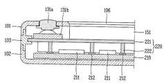
도 4는 도 3의 중간 케이스를 배면에서 바라본 사시도이고, 도 5는 도 1의 Ⅴ-Ⅴ 라인을 따르는 휴대 단말기의 단면도이다.4 is a perspective view of the intermediate case of FIG. 3 viewed from the back, and FIG. 5 is a cross-sectional view of the mobile terminal along the line VV of FIG. 1.
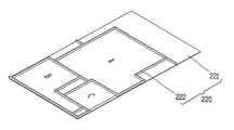
도 4를 참조하면, 중간 케이스(103)에는 인쇄회로기판(210)에 배치된 전자 소자(211)들을 전기적으로 차폐하는 차폐 부재(220)가 구비된다.Referring to FIG. 4, the
차폐 부재(220)는 중간 케이스(103)의 적어도 일부를 이루도록 구성되며, 금속 재질{예를 들어, 스테인레스 스틸(STS)}을 갖는다. 차폐 부재(220)는 중간 케이스(103)와 인쇄회로기판(210) 사이의 차폐 영역(예를 들어, 도 4의 A,B,C 영역)을 한정하도록 구성된다.The
중간 케이스(103)가 합성수지 재질로 형성되는 경우, 중간 케이스(103)는 차폐 부재(210)와 함께 인서트 사출 성형에 의해 형성될 수 있다. 이와 같은 제조 방법에 의하여, 중간 케이스(103)와 차폐 부재(220)는 일체로 형성될 수 있다.When the
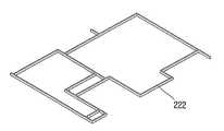
차폐 부재(220)는 베이스(221)와, 베이스(221)에서 인쇄회로기판(210)이 위치한 방향으로 연장되는 연장부(222)를 포함할 수 있다.The shielding
베이스(221)는 금속 재질의 플레이트 형태로 형성되며, 중간 케이스(103)의 일면을 이루도록 형성된다. 본 실시예에 따르면, 베이스(221)는 중간 케이스(103)의 전면(front surface)와 후면(rear surface)를 이룬다.The
도 5를 참조하면, 베이스(221)는 인쇄회로기판(210)과 마주하는 제1면(221a)과, 제1면(221a)과 반대 방향을 갖는 제2면(221b)을 구비한다. 여기서, 제1면(221 a)은 중간 케이스(103)의 후면(rear surface)에 대응되고, 제2면(221b)는 중간 케이스(103)의 전면(front surface)에 대응된다.Referring to FIG. 5, the
중간 케이스(103)는 제1면(221a)과 제2면(221b)의 적어도 일 영역을 감싸도록 형성된다. 중간 케이스(103)는 베이스(221)의 테두리에 해당하는 영역을 감싸도록 구성될 수 있다.The
연장부(222)는 도전성 재질, 예를 들어 베이스(221)와 마찬가지로 금속재질로 형성될 수 있다. 연장부(222)는 제1면(221a)으로부터 인쇄회로기판(210)을 향하여 연장되며, 인쇄회로기판(210)의 금속 패턴(212)에 접촉된다. 연장부(222)는 적어도 전자 소자(211)의 높이보다 높은 높이를 가진다.The
연장부(222)는 차폐 영역(예를 들어, 도 4의 A,B,C 영역)의 둘레를 따라 형 성되며, 차폐 영역들 사이를 구획할 수 있도록 복수개로 형성될 수 있다. 연장부(222)와 금속 패턴(212)은 서로 접촉될 수 있도록 서로 대응되는 패턴을 가질 수 있다.The
연장부(222)는 베이스(221)와 별도의 부재로서 베이스(222)에 부착될 수도 있고, 베이스(221)와 일체로 형성될 수도 있다. 본 실시예에서는 연장부(222)가 별도의 부재로서 베이스(221)에 부착되는 것을 기초로 설명한다.The
한편, 베이스(212)의 제2면에는 디스플레이 모듈(151)이 장착되며, 프론트 케이스(101)에는 투광성 재질의 윈도우(106)가 장착될 수 있다.The
도 6a는 연장부의 구성의 일예를 나타내는 사시도이다.6A is a perspective view illustrating an example of a configuration of an extension part.
도 6a를 참조하면, 연장부(222)는 리브(rib) 형태로 형성되는 접촉부(223)와, 베이스(221)에 용접되는 용접부(224)를 포함할 수 있다.Referring to FIG. 6A, the
용접부(224)는 베이스(221)에 용접 가능하도록 일정 면적을 갖는다. 그리고, 접촉부(223)는 용접부(224)로부터 연장되며, 인쇄회로기판(210)의 금속 패턴(212)과 접촉되는 접촉면을 구비한다.The
도 6b는 연장부의 구성의 다른 예를 나타내는 사시도이다.6B is a perspective view illustrating another example of the configuration of the extension part.
도 6b를 참조하면, 연장부(222)는 앞선 예와 마찬가지로 접촉부(225)와, 용접부(226)로 구성될 수 있다. 본 예에 의하면 접촉부(225)는 용접부(226)의 일 영역이 절개되어 형성된다. 접촉부(225)는 인쇄회로기판(210)의 금속 패턴(211)과의 접촉면을 갖도록 절곡된 형태를 가지며, 용접부(226)의 길이 방향을 따라 복수로 형성된다.Referring to FIG. 6B, the
도 6a 및 6b에서 설명된 접촉부(225)에는 금속 패턴(212)와의 탄력적인 접촉을 위하여 도전성 탄성 부재(예를 들어, 도전성 고무)가 추가로 부착될 수 있다.Conductive elastic members (eg, conductive rubber) may be further attached to the
이하에서는 도 4 및 5를 참조하여 본 발명과 관련된 휴대 단말기의 작동 상태를 설명한다.Hereinafter, an operating state of the mobile terminal according to the present invention will be described with reference to FIGS. 4 and 5.
본 발명과 관련된 차폐 부재(220)는 인쇄회로기판(210)의 금속 패턴(212)에 접촉되어 중간 케이스(103)와 인쇄회로기판(210) 사이의 차폐 영역들(예를 들어, 도 4의 A,B,C 영역들)을 한정한다.The shielding
차폐 부재(220)는 각 차폐 영역들을 한정함으로써 단말기 바디 외부의 전자파로부터 전자 소자(211)들을 보호하며, 인쇄회로기판(210)의 각 영역들에 실장된 전자 소자들간의 간섭이 발생하는 것을 방지한다.The shielding
단말기 바디 외부의 전자파는 베이스(221)에 흡수되게 되어 차폐 부재(220) 내부로 전자파가 도달하지 못하게 된다. 또한, 도 4의 어느 일 차폐 영역(예를 들어, A 영역)에 실장된 전자소자(211)에서 발생한 전자파는 베이스(221)와 연장부(222)에 흡수되게 된다. 이에 따라 A영역의 전자파가 B 또는 C 영역으로 진입하는 것이 방지될 수 있다. 차폐 부재(220)에 흡수된 전자파는 전류의 형태로서 금속 패턴(212)으로 흐르게 되어 그라운드로 소산되게 된다.Electromagnetic waves outside the terminal body are absorbed by the base 221 so that electromagnetic waves cannot reach the shielding
본 발명은 차폐 부재(220)를 케이스에 일체로 형성시킴으로써 단말기 바디의 두께를 보다 슬림화할 수 있으며, 실드캔(shield can)을 인쇄회로기판에 장착하는 것과 대비하여 조립 공정을 간소화할 수 있다. 또한, 케이스가 합성 수지 재질로 형성되는 경우, 금속 재질의 차폐 부재(220)가 케이스의 일부를 이루도록 함으로써 케이스의 강성을 향상시킬 수 있다.According to the present invention, the thickness of the terminal body can be reduced by forming the shielding
도 7a 내지 7c는 이상에서 설명된 구성을 갖는 중간 케이스의 제조 공정을 나타내는 도면들이다.7A to 7C are views showing a manufacturing process of an intermediate case having the above-described configuration.
먼저, 도 7a와 같이 연장부(222)가 마련된다. 연장부(222)는 인쇄회로기판(210)에 실장되는 전자소자(211)의 배치 형태와 금속 패턴(212)의 형태에 따라 다양한 형태로 제조될 수 있다.First, an
로드 형태를 갖는 금속 부재의 일영역을 절개한 후 절곡함으로써, 앞서 설명된 접촉부(223,225)와 접촉부(224,226)를 형성할 수 있다.By cutting and then bending one region of the metal member having a rod shape, the
다음으로, 도 7b와 같이 연장부(222)를 베이스(221)에 부착한다. 여기서 연장부(222)는 레이저 용접에 의하여 베이스(221)에 부착될 수 있다. 이에 따라 앞서 설명된 차폐 부재(220)가 완성된다.Next, the
본 실시예에서 설명되는 공정 이외에도 베이스(221)와 연장부(222)는 함께 일체로 형성되는 것도 가능하다 할 것이다.In addition to the process described in the present embodiment, the
마지막으로, 도 7c와 같이 차폐 부재(220)의 둘레에 중간 케이스(103)을 형성시킨다. 중간 케이스(103)와 차폐 부재(220) 인서트 사출 공정에 의하여 일체로 성형될 수 있다. 즉, 도 7b의 공정에서 완성된 차폐부재와, 합성 수지를 동일한 금형을 통해 함께 성형함으로써 중간 케이스(103)를 사출할 수 있다.Finally, the
도 8은 본 발명과 관련하여 다른 형태를 갖는 휴대 단말기의 사시도이다. 본 실시예는 휴대 단말기가 슬라이드 타입을 갖는 것을 예시하고 있다. 본 도면에서는 도 1에서 설명된 구성과 동일한 구성에 대하여 유사한 도면 부호를 부여하였으며, 동일한 구성에 대해서는 그 설명은 생략하기로 한다.8 is a perspective view of a portable terminal having another form in accordance with the present invention. This embodiment illustrates that the mobile terminal has a slide type. In the drawings, similar reference numerals are given to the same components as those described in FIG. 1, and descriptions of the same components will be omitted.
본 발명의 휴대 단말기(300)는 제1바디(300')와, 제1바디(300')에 적어도 일 방향을 따라 슬라이딩 가능하게 구성된 제2바디(300")를 포함한다.The
제1바디(300')가 제2바디(300")와 중첩되게 배치된 상태를 닫힌 상태(closed configuration)라 칭할 수 있으며, 본 도면에 도시된 바와 같이 제1바디(300')가 제2바디(300")의 적어도 일 부분을 노출한 상태를 열린 상태(open configuration)라 칭할 수 있다.A state in which the
휴대 단말기(300)는 닫힌 상태에서 주로 대기 모드로 작동하지만 사용자의 조작에 의해 대기 모드가 해제되기도 한다. 그리고, 휴대 단말기(300)는 열린 상태에서 주로 통화 모드 등으로 작동하지만 사용자의 조작 또는 소정 시간의 경과에 의해 대기 모드로 전환되기도 한다.Although the
제1바디(300')에는 디스플레이부(351), 음향출력부(352), 카메라(321), 제1조작부(331) 등이 배치되고, 제2바디(300")에는 제2 및 제3조작부(332,333), 음향입력부(322), 인터페이스부(370), 전원공급부(390) 등이 배치된다.The
본 실시예에 따르면, 제1바디(300')는 프론트 케이스(301)와, 리어 케이스(302)에 의하여 형성된다. 그리고, 제2바디(300") 또한 제1바디(300')와 마찬가지로 프론트 케이스(301)와 리어 케이스(302)에 의해 형성될 수 있다.According to the present embodiment, the
도 9는 도 8의 Ⅸ-Ⅸ 라인을 따르는 휴대 단말기의 단면도이다.9 is a cross-sectional view of the mobile terminal along the VIII-VIII line in FIG. 8.
도 9를 참조하면, 프론트 케이스(301)와 리어 케이스(302) 사이에 형성된 공간에는 인쇄회로기판(410)이 장착된다.Referring to FIG. 9, a printed
인쇄회로기판(410)의 전면에는 디스플레이부(151)가 장착되며, 후면에는 전자 소자(411)들이 장착된다. 그리고, 인쇄회로기판(410)에는 앞선 실시예와 마찬가지로 차폐 영역들을 구획하기 위한 금속 패턴(412)이 형성된다.The
본 실시예에 의한 차폐 부재(420)는 리어 케이스(302)의 일부를 이루도록 형성된다. 즉, 리어 케이스(302)와 차폐 부재(420)는 인서트 사출 성형에 의하여 일체로 형성될 수 있다.The shielding
차폐 부재(420)는 앞선 실시예와 마찬가지로 베이스(421)와, 연장부(422)를 포함하여 이루어질 수 있다. 연장부(422)는 베이스(421)의 제1면(421a)으로부터 연장되어 금속 패턴(412)에 접촉한다.The shielding
리어 케이스(302)는 베이스(421)의 제2면(421b)을 덮도록 형성되어 베이스(421)가 외부로 노출되지 않도록 한다. 즉, 앞선 실시예와 달리 케이스가 프론트 케이스(301)와 리어 케이스(302)로 이루어지는 경우, 케이스는 베이스(421)의 제2면(421b)을 덮도록 사출될 수 있다.The
도 10은 본 발명의 일 실시예와 관련된 휴대 단말기의 블록 구성도(block diagram)이다.10 is a block diagram of a portable terminal related to an embodiment of the present invention.
상기 휴대 단말기(100)는 무선 통신부(110), A/V(Audio/Video) 입력부(120), 사용자 입력부(130), 센싱부(140), 출력부(150), 메모리(160), 인터페이스부(170), 제어부(180) 및 전원 공급부(190) 등을 포함할 수 있다. 도 10에 도시된 구성요소들이 필수적인 것은 아니어서, 그보다 많은 구성요소들을 갖거나 그보다 적은 구성요소들을 갖는 휴대 단말기가 구현될 수도 있다.The
이하, 상기 구성요소들에 대해 차례로 살펴본다.Hereinafter, the components will be described in order.
무선 통신부(110)는 휴대 단말기(100)와 무선 통신 시스템 사이 또는 휴대 단말기(100)와 휴대 단말기(100)가 위치한 네트워크 사이의 무선 통신을 가능하게 하는 하나 이상의 모듈을 포함할 수 있다. 예를 들어, 무선 통신부(110)는 방송 수신 모듈(111), 이동통신 모듈(112), 무선 인터넷 모듈(113), 근거리 통신 모듈(114) 및 위치정보 모듈(115) 등을 포함할 수 있다.The
방송 수신 모듈(111)은 방송 채널을 통하여 외부의 방송 관리 서버로부터 방송 신호 및/또는 방송 관련된 정보를 수신한다.The
상기 방송 채널은 위성 채널, 지상파 채널을 포함할 수 있다. 상기 방송 관리 서버는, 방송 신호 및/또는 방송 관련 정보를 생성하여 송신하는 서버 또는 기 생성된 방송 신호 및/또는 방송 관련 정보를 제공받아 단말기에 송신하는 서버를 의미할 수 있다. 상기 방송 신호는, TV 방송 신호, 라디오 방송 신호, 데이터 방송 신호를 포함할 뿐만 아니라, TV 방송 신호 또는 라디오 방송 신호에 데이터 방송 신호가 결합한 형태의 방송 신호도 포함할 수 있다.The broadcast channel may include a satellite channel and a terrestrial channel. The broadcast management server may mean a server that generates and transmits a broadcast signal and / or broadcast related information or a server that receives a previously generated broadcast signal and / or broadcast related information and transmits the same to a terminal. The broadcast signal may include not only a TV broadcast signal, a radio broadcast signal, and a data broadcast signal, but also a broadcast signal having a data broadcast signal combined with a TV broadcast signal or a radio broadcast signal.
상기 방송 관련 정보는, 방송 채널, 방송 프로그램 또는 방송 서비스 제공자에 관련한 정보를 의미할 수 있다. 상기 방송 관련 정보는, 이동통신망을 통하여도 제공될 수 있다. 이러한 경우에는 상기 이동통신 모듈(112)에 의해 수신될 수 있다.The broadcast related information may mean information related to a broadcast channel, a broadcast program, or a broadcast service provider. The broadcast related information may also be provided through a mobile communication network. In this case, it may be received by the
상기 방송 관련 정보는 다양한 형태로 존재할 수 있다. 예를 들어, DMB(Digital Multimedia Broadcasting)의 EPG(Electronic Program Guide) 또는 DVB-H(Digital Video Broadcast-Handheld)의 ESG(Electronic Service Guide) 등의 형태로 존재할 수 있다.The broadcast related information may exist in various forms. For example, it may exist in the form of Electronic Program Guide (EPG) of Digital Multimedia Broadcasting (DMB) or Electronic Service Guide (ESG) of Digital Video Broadcast-Handheld (DVB-H).
상기 방송 수신 모듈(111)은, 예를 들어, DMB-T(Digital Multimedia Broadcasting-Terrestrial), DMB-S(Digital Multimedia Broadcasting-Satellite), MediaFLO(Media Forward Link Only), DVB-H(Digital Video Broadcast-Handheld), ISDB-T(Integrated Services Digital Broadcast-Terrestrial) 등의 디지털 방송 시스템을 이용하여 디지털 방송 신호를 수신할 수 있다. 물론, 상기 방송 수신 모듈(111)은, 상술한 디지털 방송 시스템뿐만 아니라 다른 방송 시스템에 적합하도록 구성될 수도 있다.The
방송 수신 모듈(111)을 통해 수신된 방송 신호 및/또는 방송 관련 정보는 메모리(160)에 저장될 수 있다.The broadcast signal and / or broadcast related information received through the
이동통신 모듈(112)은, 이동 통신망 상에서 기지국, 외부의 단말, 서버 중 적어도 하나와 무선 신호를 송수신한다. 상기 무선 신호는, 음성 호 신호, 화상 통화 호 신호 또는 문자/멀티미디어 메시지 송수신에 따른 다양한 형태의 데이터를 포함할 수 있다.The
무선 인터넷 모듈(113)은 무선 인터넷 접속을 위한 모듈을 말하는 것으로, 휴대 단말기(100)에 내장되거나 외장될 수 있다. 무선 인터넷 기술로는 WLAN(Wireless LAN)(Wi-Fi), Wibro(Wireless broadband), Wimax(World Interoperability for Microwave Access), HSDPA(High Speed Downlink Packet Access) 등이 이용될 수 있다.The
근거리 통신 모듈(114)은 근거리 통신을 위한 모듈을 말한다. 근거리 통신(short range communication) 기술로 블루투스(Bluetooth), RFID(Radio Frequency Identification), 적외선 통신(IrDA, infrared Data Association), UWB(Ultra Wideband), ZigBee 등이 이용될 수 있다.The short
위치정보 모듈(115)은 휴대 단말기의 위치를 획득하기 위한 모듈로서, 그의 대표적인 예로는 GPS(Global Position System) 모듈이 있다.The
도 10을 참조하면, A/V(Audio/Video) 입력부(120)는 오디오 신호 또는 비디오 신호 입력을 위한 것으로, 이에는 카메라(121)와 마이크(122) 등이 포함될 수 있다. 카메라(121)는 화상 통화모드 또는 촬영 모드에서 이미지 센서에 의해 얻어지는 정지영상 또는 동영상 등의 화상 프레임을 처리한다. 처리된 화상 프레임은 디스플레이부(151)에 표시될 수 있다.Referring to FIG. 10, the A /
카메라(121)에서 처리된 화상 프레임은 메모리(160)에 저장되거나 무선 통신부(110)를 통하여 외부로 전송될 수 있다. 카메라(121)는 사용 환경에 따라 2개 이상이 구비될 수도 있다.The image frame processed by the
마이크(122)는 통화모드 또는 녹음모드, 음성인식 모드 등에서 마이크로폰(Microphone)에 의해 외부의 음향 신호를 입력받아 전기적인 음성 데이터로 처리한다. 처리된 음성 데이터는 통화 모드인 경우 이동통신 모듈(112)을 통하여 이동통신 기지국으로 송신 가능한 형태로 변환되어 출력될 수 있다. 마이크(122)에는 외부의 음향 신호를 입력받는 과정에서 발생되는 잡음(noise)을 제거하기 위한 다양한 잡음 제거 알고리즘이 구현될 수 있다.The
사용자 입력부(130)는 사용자가 단말기의 동작 제어를 위한 입력 데이터를 발생시킨다. 사용자 입력부(130)는 키 패드(key pad) 돔 스위치 (dome switch), 터치 패드(정압/정전), 조그 휠, 조그 스위치 등으로 구성될 수 있다.The user input unit 130 generates input data for the user to control the operation of the terminal. The user input unit 130 may include a key pad dome switch, a touch pad (static pressure / capacitance), a jog wheel, a jog switch, and the like.
센싱부(140)는 휴대 단말기(100)의 개폐 상태, 휴대 단말기(100)의 위치, 사용자 접촉 유무, 휴대 단말기의 방위, 휴대 단말기의 가속/감속 등과 같이 휴대 단말기(100)의 현 상태를 감지하여 휴대 단말기(100)의 동작을 제어하기 위한 센싱 신호를 발생시킨다. 예를 들어 휴대 단말기(100)가 슬라이드 폰 형태인 경우 슬라이드 폰의 개폐 여부를 센싱할 수 있다. 또한, 전원 공급부(190)의 전원 공급 여부, 인터페이스부(170)의 외부 기기 결합 여부 등을 센싱할 수도 있다. 한편, 상기 센싱부(140)는 근접 센서(141)를 포함할 수 있다.The
출력부(150)는 시각, 청각 또는 촉각 등과 관련된 출력을 발생시키기 위한 것으로, 이에는 디스플레이부(151), 음향 출력 모듈(152), 알람부(153), 및 햅틱 모듈(154) 등이 포함될 수 있다.The
디스플레이부(151)는 휴대 단말기(100)에서 처리되는 정보를 표시(출력)한다. 예를 들어, 휴대 단말기가 통화 모드인 경우 통화와 관련된 UI(User Interface) 또는 GUI(Graphic User Interface)를 표시한다. 휴대 단말기(100)가 화상 통화 모드 또는 촬영 모드인 경우에는 촬영 또는/및 수신된 영상 또는 UI, GUI를 표시한다.The
디스플레이부(151)는 액정 디스플레이(liquid crystal display, LCD), 박막 트랜지스터 액정 디스플레이(thin film transistor-liquid crystal display, TFT LCD), 유기 발광 다이오드(organic light-emitting diode, OLED), 플렉시블 디스플레이(flexible display), 3차원 디스플레이(3D display) 중에서 적어도 하나를 포함할 수 있다.The
이들 중 일부 디스플레이는 그를 통해 외부를 볼 수 있도록 투명형 또는 광투과형으로 구성될 수 있다. 이는 투명 디스플레이라 호칭될 수 있는데, 상기 투명 디스플레이의 대표적인 예로는 TOLED(Transparant OLED) 등이 있다. 디스플레이부(151)의 후방 구조 또한 광 투과형 구조로 구성될 수 있다. 이러한 구조에 의하여, 사용자는 단말기 바디의 디스플레이부(151)가 차지하는 영역을 통해 단말기 바디의 후방에 위치한 사물을 볼 수 있다.Some of these displays can be configured to be transparent or light transmissive so that they can be seen from the outside. This may be referred to as a transparent display. A representative example of the transparent display is TOLED (Transparant OLED). The rear structure of the
휴대 단말기(100)의 구현 형태에 따라 디스플레이부(151)이 2개 이상 존재할 수 있다. 예를 들어, 휴대 단말기(100)에는 복수의 디스플레이부들이 하나의 면에 이격되거나 일체로 배치될 수 있고, 또한 서로 다른 면에 각각 배치될 수도 있다.There may be two or
디스플레이부(151)와 터치 동작을 감지하는 센서(이하, '터치 센서'라 함)가 상호 레이어 구조를 이루는 경우(이하, '터치 스크린'이라 함)에, 디스플레이부(151)는 출력 장치 이외에 입력 장치로도 사용될 수 있다. 터치 센서는, 예를 들어, 터치 필름, 터치 시트, 터치 패드 등의 형태를 가질 수 있다.When the
터치 센서는 디스플레이부(151)의 특정 부위에 가해진 압력 또는 디스플레이부(151)의 특정 부위에 발생하는 정전 용량 등의 변화를 전기적인 입력신호로 변환하도록 구성될 수 있다. 터치 센서는 터치 되는 위치 및 면적뿐만 아니라, 터치 시의 압력까지도 검출할 수 있도록 구성될 수 있다.The touch sensor may be configured to convert a change in pressure applied to a specific portion of the
터치 센서에 대한 터치 입력이 있는 경우, 그에 대응하는 신호(들)는 터치 제어기로 보내진다. 터치 제어기는 그 신호(들)를 처리한 다음 대응하는 데이터를 제어부(180)로 전송한다. 이로써, 제어부(180)는 디스플레이부(151)의 어느 영역이 터치 되었는지 여부 등을 알 수 있게 된다.If there is a touch input to the touch sensor, the corresponding signal (s) is sent to the touch controller. The touch controller processes the signal (s) and then transmits the corresponding data to the
도 10을 참조하면, 상기 터치스크린에 의해 감싸지는 휴대 단말기의 내부 영역 또는 상기 터치 스크린의 근처에 근접 센서(141)가 배치될 수 있다. 상기 근접 센서는 소정의 검출면에 접근하는 물체, 혹은 근방에 존재하는 물체의 유무를 전자계의 힘 또는 적외선을 이용하여 기계적 접촉이 없이 검출하는 센서를 말한다. 근접 센서는 접촉식 센서보다는 그 수명이 길며 그 활용도 또한 높다.Referring to FIG. 10, a
음향 출력 모듈(152)은 호신호 수신, 통화모드 또는 녹음 모드, 음성인식 모드, 방송수신 모드 등에서 무선 통신부(110)로부터 수신되거나 메모리(160)에 저장된 오디오 데이터를 출력할 수 있다. 음향 출력 모듈(152)은 휴대 단말기(100)에서 수행되는 기능(예를 들어, 호신호 수신음, 메시지 수신음 등)과 관련된 음향 신호를 출력하기도 한다. 이러한 음향 출력 모듈(152)에는 리시버(Receiver), 스피커(speaker), 버저(Buzzer) 등이 포함될 수 있다.The
알람부(153)는 휴대 단말기(100)의 이벤트 발생을 알리기 위한 신호를 출력한다. 휴대 단말기에서 발생 되는 이벤트의 예로는 호 신호 수신, 메시지 수신, 키 신호 입력, 터치 입력 등이 있다. 알람부(153)는 비디오 신호나 오디오 신호 이외에 다른 형태, 예를 들어 진동으로 이벤트 발생을 알리기 위한 신호를 출력할 수도 있다. 상기 비디오 신호나 오디오 신호는 디스플레이부(151)나 음성 출력 모 듈(152)을 통해서도 출력될 수 있어서, 그들(151,152)은 알람부(153)의 일부로 분류될 수도 있다.The
햅틱 모듈(haptic module)(154)은 사용자가 느낄 수 있는 다양한 촉각 효과를 발생시킨다. 햅틱 모듈(154)이 발생시키는 촉각 효과의 대표적인 예로는 진동이 있다. 햅택 모듈(154)이 발생하는 진동의 세기와 패턴 등은 제어가능하다. 예를 들어, 서로 다른 진동을 합성하여 출력하거나 순차적으로 출력할 수도 있다.The
햅틱 모듈(154)은, 진동 외에도, 접촉 피부면에 대해 수직 운동하는 핀 배열, 분사구나 흡입구를 통한 공기의 분사력이나 흡입력, 피부 표면에 대한 스침, 전극(eletrode)의 접촉, 정전기력 등의 자극에 의한 효과와, 흡열이나 발열 가능한 소자를 이용한 냉온감 재현에 의한 효과 등 다양한 촉각 효과를 발생시킬 수 있다.In addition to vibration, the
햅틱 모듈(154)은 직접적인 접촉을 통해 촉각 효과의 전달할 수 있을 뿐만 아니라, 사용자가 손가락이나 팔 등의 근 감각을 통해 촉각 효과를 느낄 수 있도록 구현할 수도 있다. 햅틱 모듈(154)은 휴대 단말기(100)의 구성 태양에 따라 2개 이상이 구비될 수 있다.The
메모리(160)는 제어부(180)의 동작을 위한 프로그램을 저장할 수 있고, 입/출력되는 데이터들(예를 들어, 폰북, 메시지, 정지영상, 동영상 등)을 임시 저장할 수도 있다. 상기 메모리(160)는 상기 터치스크린 상의 터치 입력시 출력되는 다양한 패턴의 진동 및 음향에 관한 데이터를 저장할 수 있다.The
메모리(160)는 플래시 메모리 타입(flash memory type), 하드디스크 타입(hard disk type), 멀티미디어 카드 마이크로 타입(multimedia card micro type), 카드 타입의 메모리(예를 들어 SD 또는 XD 메모리 등), 램(Random Access Memory, RAM), SRAM(Static Random Access Memory), 롬(Read-Only Memory, ROM), EEPROM(Electrically Erasable Programmable Read-Only Memory), PROM(Programmable Read-Only Memory), 자기 메모리, 자기 디스크, 광디스크 중 적어도 하나의 타입의 저장매체를 포함할 수 있다. 휴대 단말기(100)는 인터넷(internet)상에서 상기 메모리(160)의 저장 기능을 수행하는 웹 스토리지(web storage)와 관련되어 동작할 수도 있다.The
인터페이스부(170)는 휴대 단말기(100)에 연결되는 모든 외부기기와의 통로 역할을 한다. 인터페이스부(170)는 외부 기기로부터 데이터를 전송받거나, 전원을 공급받아 휴대 단말기(100) 내부의 각 구성 요소에 전달하거나, 휴대 단말기(100) 내부의 데이터가 외부 기기로 전송되도록 한다. 예를 들어, 유/무선 헤드셋 포트, 외부 충전기 포트, 유/무선 데이터 포트, 메모리 카드(memory card) 포트, 식별 모듈이 구비된 장치를 연결하는 포트, 오디오 I/O(Input/Output) 포트, 비디오 I/O(Input/Output) 포트, 이어폰 포트 등이 인터페이스부(170)에 포함될 수 있다.The
식별 모듈은 휴대 단말기(100)의 사용 권한을 인증하기 위한 각종 정보를 저장한 칩으로서, 사용자 인증 모듈(User Identify Module, UIM), 가입자 인증 모듈(Subscriber Identify Module, SIM), 범용 사용자 인증 모듈(Universal Subscriber Identity Module, USIM) 등을 포함할 수 있다. 식별 모듈이 구비된 장치(이하 '식별 장치')는, 스마트 카드(smart card) 형식으로 제작될 수 있다. 따라서 식별 장치는 포트를 통하여 단말기(100)와 연결될 수 있다.The identification module is a chip that stores various types of information for authenticating the use authority of the
인터페이스부(170)는 휴대 단말기(100)가 외부 크래들(cradle)과 연결될 때 상기 크래들로부터의 전원이 상기 휴대 단말기(100)에 공급되는 통로가 되거나, 사용자에 의해 상기 크래들에서 입력되는 각종 명령 신호가 상기 휴대 단말기로 전달되는 통로가 될 수 있다. 상기 크래들로부터 입력되는 각종 명령 신호 또는 상기 전원은 상기 휴대 단말기가 상기 크래들에 정확히 장착되었음을 인지하기 위한 신호로 동작될 수도 있다.The
제어부(controller, 180)는 통상적으로 휴대 단말기의 전반적인 동작을 제어한다. 예를 들어 음성 통화, 데이터 통신, 화상 통화 등을 위한 관련된 제어 및 처리를 수행한다. 제어부(180)는 멀티 미디어 재생을 위한 멀티미디어 모듈(181)을 구비할 수도 있다. 멀티미디어 모듈(181)은 제어부(180) 내에 구현될 수도 있고, 제어부(180)와 별도로 구현될 수도 있다.The
제어부(180)는 상기 터치스크린 상에서 행해지는 필기 입력 또는 그림 그리기 입력을 각각 문자 및 이미지로 인식할 수 있는 패턴 인식 처리를 행할 수 있다.The
전원 공급부(190)는 제어부(180)의 제어에 의해 외부의 전원, 내부의 전원을 인가받아 각 구성요소들의 동작에 필요한 전원을 공급한다.The
여기에 설명되는 다양한 실시예는 예를 들어, 소프트웨어, 하드웨어 또는 이들의 조합된 것을 이용하여 컴퓨터 또는 이와 유사한 장치로 읽을 수 있는 기록매체 내에서 구현될 수 있다.Various embodiments described herein may be implemented in a recording medium readable by a computer or similar device using, for example, software, hardware or a combination thereof.
하드웨어적인 구현에 의하면, 여기에 설명되는 실시예는 ASICs (application specific integrated circuits), DSPs (digital signal processors), DSPDs (digital signal processing devices), PLDs (programmable logic devices), FPGAs (field programmable gate arrays, 프로세서(processors), 제어기(controllers), 마이크로 컨트롤러(micro-controllers), 마이크로 프로세서(microprocessors), 기타 기능 수행을 위한 전기적인 유닛 중 적어도 하나를 이용하여 구현될 수 있다. 일부의 경우에 본 명세서에서 설명되는 실시예들이 제어부(180) 자체로 구현될 수 있다.According to a hardware implementation, the embodiments described herein include application specific integrated circuits (ASICs), digital signal processors (DSPs), digital signal processing devices (DSPDs), programmable logic devices (PLDs), field programmable gate arrays (FPGAs), and the like. It may be implemented using at least one of processors, controllers, micro-controllers, microprocessors, and electrical units for performing other functions. The described embodiments may be implemented by the
소프트웨어적인 구현에 의하면, 본 명세서에서 설명되는 절차 및 기능과 같은 실시예들은 별도의 소프트웨어 모듈들로 구현될 수 있다. 상기 소프트웨어 모듈들 각각은 본 명세서에서 설명되는 하나 이상의 기능 및 작동을 수행할 수 있다. 적절한 프로그램 언어로 쓰여진 소프트웨어 어플리케이션으로 소프트웨어 코드가 구현될 수 있다. 상기 소프트웨어 코드는 메모리(160)에 저장되고, 제어부(180)에 의해 실행될 수 있다.According to the software implementation, embodiments such as the procedures and functions described herein may be implemented as separate software modules. Each of the software modules may perform one or more functions and operations described herein. Software code may be implemented in software applications written in a suitable programming language. The software code may be stored in the
상기와 같은 휴대 단말기는 위에서 설명된 실시예들의 구성과 방법에 한정되는 것이 아니라, 상기 실시예들은 다양한 변형이 이루어질 수 있도록 각 실시예들의 전부 또는 일부가 선택적으로 조합되어 구성될 수도 있다.The portable terminal is not limited to the configuration and method of the embodiments described above, but the embodiments may be configured by selectively combining all or some of the embodiments so that various modifications can be made.
도 1은 본 발명의 일 실시예에 관련된 휴대 단말기의 전면 사시도.1 is a front perspective view of a mobile terminal according to an embodiment of the present invention;
도 2는 본 발명의 일 실시예에 관련된 휴대 단말기의 후면 사시도.2 is a rear perspective view of a mobile terminal according to an embodiment of the present invention;
도 3은 본 발명의 일실시예와 관련된 휴대 단말기의 분해 사시도.3 is an exploded perspective view of a mobile terminal related to one embodiment of the present invention;
도 4는 도 3의 중간 케이스를 배면에서 바라본 사시도.4 is a perspective view of the intermediate case of FIG.
도 5는 도 1의 Ⅴ-Ⅴ 라인을 따르는 휴대 단말기의 단면도.5 is a cross-sectional view of the mobile terminal along the line VV of FIG.
도 6a 및 6b는 연장부의 구성의 일예와 다른 예를 각각 나타내는 사시도.6A and 6B are perspective views each showing one example and another example of the configuration of the extension portion;
도 7a 내지 7c는 도 4의 중간 케이스의 제조 공정을 나타내는 도면들.7A to 7C are views illustrating a manufacturing process of the intermediate case of FIG. 4.
도 8은 본 발명과의 다른 실시예와 관련된 휴대 단말기의 사시도.8 is a perspective view of a mobile terminal related to another embodiment of the present invention;
도 9는 도 8의 Ⅸ-Ⅸ 라인을 따르는 휴대 단말기의 단면도.9 is a cross-sectional view of the mobile terminal along the VIII-VIII line in FIG. 8;
도 10은 본 발명의 일 실시예에 관련된 휴대 단말기의 블록 구성도.10 is a block diagram of a portable terminal according to an embodiment of the present invention.
Claims (13)
Translated fromKoreanPriority Applications (2)
| Application Number | Priority Date | Filing Date | Title |
|---|---|---|---|
| KR1020080105502AKR20100046594A (en) | 2008-10-27 | 2008-10-27 | Portable terminal |
| US12/567,990US8958855B2 (en) | 2008-10-27 | 2009-09-28 | Mobile terminal having shielding member |
Applications Claiming Priority (1)
| Application Number | Priority Date | Filing Date | Title |
|---|---|---|---|
| KR1020080105502AKR20100046594A (en) | 2008-10-27 | 2008-10-27 | Portable terminal |
Publications (1)
| Publication Number | Publication Date |
|---|---|
| KR20100046594Atrue KR20100046594A (en) | 2010-05-07 |
Family
ID=42118029
Family Applications (1)
| Application Number | Title | Priority Date | Filing Date |
|---|---|---|---|
| KR1020080105502ACeasedKR20100046594A (en) | 2008-10-27 | 2008-10-27 | Portable terminal |
Country Status (2)
| Country | Link |
|---|---|
| US (1) | US8958855B2 (en) |
| KR (1) | KR20100046594A (en) |
Cited By (5)
| Publication number | Priority date | Publication date | Assignee | Title |
|---|---|---|---|---|
| KR20130025671A (en)* | 2011-09-02 | 2013-03-12 | 엘지전자 주식회사 | Mobile terminal |
| KR20130095086A (en)* | 2012-02-17 | 2013-08-27 | 엘지전자 주식회사 | Mobile terminal |
| KR20130137987A (en)* | 2012-06-08 | 2013-12-18 | 엘지전자 주식회사 | Mobile terminal |
| KR20140065262A (en)* | 2012-11-21 | 2014-05-29 | 엘지전자 주식회사 | Mobile terminal and method for fabricating the same |
| US10306816B2 (en) | 2016-10-21 | 2019-05-28 | Samsung Electronics Co., Ltd. | EMI shielding structure |
Families Citing this family (58)
| Publication number | Priority date | Publication date | Assignee | Title |
|---|---|---|---|---|
| KR20100046594A (en)* | 2008-10-27 | 2010-05-07 | 엘지전자 주식회사 | Portable terminal |
| US9172134B2 (en)* | 2008-11-06 | 2015-10-27 | Antenna79, Inc. | Protective cover for a wireless device |
| KR101658821B1 (en) | 2009-12-24 | 2016-10-04 | 삼성전자주식회사 | Shield can of mobile terminal |
| USD633908S1 (en) | 2010-04-19 | 2011-03-08 | Apple Inc. | Electronic device |
| USD627778S1 (en) | 2010-04-19 | 2010-11-23 | Apple Inc. | Electronic device |
| USD864949S1 (en) | 2010-04-19 | 2019-10-29 | Apple Inc. | Electronic device |
| USD666202S1 (en) | 2010-06-05 | 2012-08-28 | Apple Inc. | Housing plate |
| USD677665S1 (en) | 2010-09-30 | 2013-03-12 | Apple Inc. | Housing for an electronic device |
| USD662922S1 (en) | 2010-10-01 | 2012-07-03 | Apple Inc. | Front cover of an electronic device |
| US8583187B2 (en) | 2010-10-06 | 2013-11-12 | Apple Inc. | Shielding structures for wireless electronic devices with displays |
| US9099771B2 (en) | 2011-01-11 | 2015-08-04 | Apple Inc. | Resonating element for reducing radio-frequency interference in an electronic device |
| USD697918S1 (en) | 2011-02-04 | 2014-01-21 | Apple Inc. | Component of an electronic device |
| USD677666S1 (en) | 2011-02-04 | 2013-03-12 | Apple Inc. | Backplate of an electronic device |
| BR202012004686Y1 (en) | 2011-07-13 | 2019-05-14 | Google Technology Holdings LLC | MOBILE ELECTRONIC DEVICE WITH ENHANCED IMPACT REDUCTION. |
| KR200471325Y1 (en) | 2011-07-13 | 2014-02-19 | 모토로라 모빌리티 엘엘씨 | Mobile electronic device with enhanced tolerance accumulator |
| BR202012004685Y1 (en) | 2011-07-13 | 2019-04-02 | Google Technology Holdings LLC | MOBILE ELECTRONIC DEVICE WITH IMPROVED LAMINATED CONSTRUCTION |
| BR202012004687U8 (en)* | 2011-07-13 | 2016-11-22 | Motorola Mobility Inc | MOBILE ELECTRONIC DEVICE WITH IMPROVED CHASSIS |
| KR101281974B1 (en)* | 2011-09-07 | 2013-07-05 | 주식회사 팬택 | Portable terminal havign a cooling structure |
| KR101222388B1 (en)* | 2011-10-14 | 2013-01-15 | 삼성전자주식회사 | Device for improving antenna receiving sensitivity in mobile phone |
| KR20130072608A (en)* | 2011-12-22 | 2013-07-02 | 삼성전자주식회사 | Display apparatus |
| US11432641B2 (en)* | 2012-03-30 | 2022-09-06 | Advanced Access Technologies Llc | Retractable storage system |
| US11412627B2 (en) | 2012-03-30 | 2022-08-09 | Advanced Access Technologies Llc | Multipurpose accessory and storage system |
| USD684571S1 (en) | 2012-09-07 | 2013-06-18 | Apple Inc. | Electronic device |
| USD707223S1 (en) | 2012-05-29 | 2014-06-17 | Apple Inc. | Electronic device |
| USD718753S1 (en) | 2012-09-10 | 2014-12-02 | Apple Inc. | Component for an electronic device |
| USD732539S1 (en) | 2012-05-29 | 2015-06-23 | Apple Inc. | Enclosure for communications device |
| JP2014032997A (en)* | 2012-08-01 | 2014-02-20 | Sharp Corp | Portable terminal |
| US9137918B2 (en) | 2012-09-28 | 2015-09-15 | Htc Corporation | Electronic apparatus and method for assembling the same |
| US9282668B2 (en)* | 2012-09-28 | 2016-03-08 | Htc Corporation | Electronic apparatus and method for assembling the same |
| US9332329B2 (en)* | 2012-09-28 | 2016-05-03 | Htc Corporation | Electronic apparatus |
| JP5713981B2 (en)* | 2012-10-25 | 2015-05-07 | Necパーソナルコンピュータ株式会社 | Information processing device |
| USD765084S1 (en) | 2013-09-10 | 2016-08-30 | Apple Inc. | Input for an electronic device |
| KR102094754B1 (en)* | 2013-12-03 | 2020-03-30 | 엘지전자 주식회사 | Mobile terminal |
| USD845294S1 (en) | 2014-05-05 | 2019-04-09 | Apple Inc. | Housing for an electronic device with surface ornamentation |
| USD800084S1 (en)* | 2015-09-18 | 2017-10-17 | Isaac S. Daniel | Communication device |
| KR20170103315A (en)* | 2016-03-03 | 2017-09-13 | 엘지전자 주식회사 | Mobile terminal |
| US11678445B2 (en) | 2017-01-25 | 2023-06-13 | Apple Inc. | Spatial composites |
| EP4589618A3 (en) | 2017-03-29 | 2025-10-15 | Apple Inc. | Device having integrated interface system |
| USD856337S1 (en) | 2017-08-04 | 2019-08-13 | Apple Inc. | Backplate for an electronic device |
| USD848999S1 (en) | 2017-08-04 | 2019-05-21 | Apple Inc. | Housing module for an electronic device |
| USD831025S1 (en) | 2017-08-10 | 2018-10-16 | Apple Inc. | Housing module for an electronic device |
| WO2019067772A1 (en)* | 2017-09-29 | 2019-04-04 | Mikael Silvanto | Multi-part device enclosure |
| CN111356979B (en) | 2018-05-25 | 2023-12-29 | 苹果公司 | Portable computer with dynamic display interface |
| USD964985S1 (en) | 2018-07-13 | 2022-09-27 | Apple Inc. | Electronic device |
| US11175769B2 (en) | 2018-08-16 | 2021-11-16 | Apple Inc. | Electronic device with glass enclosure |
| USD963652S1 (en) | 2018-08-23 | 2022-09-13 | Apple Inc. | Housing module for an electronic device |
| US11258163B2 (en) | 2018-08-30 | 2022-02-22 | Apple Inc. | Housing and antenna architecture for mobile device |
| US11189909B2 (en) | 2018-08-30 | 2021-11-30 | Apple Inc. | Housing and antenna architecture for mobile device |
| US10705570B2 (en) | 2018-08-30 | 2020-07-07 | Apple Inc. | Electronic device housing with integrated antenna |
| USD909388S1 (en) | 2018-09-04 | 2021-02-02 | Apple Inc. | Housing module for an electronic device |
| KR102522663B1 (en)* | 2018-10-02 | 2023-04-18 | 삼성전자주식회사 | Electronic device comprising structure connecting display and conductive supporting member with conductive adhesive member |
| TWI696104B (en)* | 2019-03-15 | 2020-06-11 | 致伸科技股份有限公司 | Touch pad module and computer using the same |
| CN114399012B (en) | 2019-04-17 | 2024-08-06 | 苹果公司 | Wireless locatable tag |
| USD905696S1 (en) | 2019-05-15 | 2020-12-22 | Apple Inc. | Backplate for an electronic device |
| USD905065S1 (en) | 2019-05-15 | 2020-12-15 | Apple Inc. | Backplate for an electronic device |
| USD974352S1 (en) | 2019-11-22 | 2023-01-03 | Apple Inc. | Electronic device |
| US12009576B2 (en) | 2019-12-03 | 2024-06-11 | Apple Inc. | Handheld electronic device |
| WO2021231221A1 (en) | 2020-05-13 | 2021-11-18 | Apple Inc. | Wearable electronic device with glass shell |
Family Cites Families (16)
| Publication number | Priority date | Publication date | Assignee | Title |
|---|---|---|---|---|
| US4718110A (en)* | 1985-10-24 | 1988-01-05 | General Electric Company | Portable two way radio with split universal device connector apparatus |
| IL84684A (en)* | 1986-12-31 | 1992-09-06 | Hughes Aircraft Co | Electronically tuneable fiber-optic receiver for narrow band microwave signal reception |
| US5456779A (en)* | 1994-06-27 | 1995-10-10 | Lockheed Missiles & Space Company, Inc. | Method of attaching antenna mesh |
| JP2866311B2 (en)* | 1994-08-29 | 1999-03-08 | 大井電気株式会社 | Message decoder sound generator |
| GB2300761B (en)* | 1995-05-12 | 1999-11-17 | Nokia Mobile Phones Ltd | Electromagnetic shield assembly |
| AU1074101A (en)* | 1999-10-12 | 2001-04-23 | Shielding For Electronics, Inc. | Emi containment apparatus |
| JP3688677B2 (en)* | 2002-11-19 | 2005-08-31 | 株式会社東芝 | Camera mounting method and portable electronic device with camera |
| US7395095B2 (en)* | 2004-05-28 | 2008-07-01 | Nokia Corporation | Mobile communication terminal |
| KR100657051B1 (en) | 2005-02-19 | 2006-12-13 | 예원플라즈마 주식회사 | Electromagnetic interference shielding case for printed circuit board and its manufacturing method |
| JP4511387B2 (en)* | 2005-02-25 | 2010-07-28 | 京セラ株式会社 | Wireless communication terminal |
| US7280855B2 (en)* | 2005-06-28 | 2007-10-09 | Research In Motion Limited | Microphone coupler for a communication device |
| KR101295050B1 (en) | 2006-09-15 | 2013-08-08 | 엘지전자 주식회사 | Printed circuit board having shield unit and mobile terminal mounted the same |
| US7629930B2 (en)* | 2006-10-20 | 2009-12-08 | Hong Kong Applied Science And Technology Research Institute Co., Ltd. | Systems and methods using ground plane filters for device isolation |
| US7764236B2 (en)* | 2007-01-04 | 2010-07-27 | Apple Inc. | Broadband antenna for handheld devices |
| JP4694517B2 (en)* | 2007-02-26 | 2011-06-08 | 京セラ株式会社 | Portable electronic devices |
| KR20100046594A (en)* | 2008-10-27 | 2010-05-07 | 엘지전자 주식회사 | Portable terminal |
- 2008
- 2008-10-27KRKR1020080105502Apatent/KR20100046594A/ennot_activeCeased
- 2009
- 2009-09-28USUS12/567,990patent/US8958855B2/enactiveActive
Cited By (5)
| Publication number | Priority date | Publication date | Assignee | Title |
|---|---|---|---|---|
| KR20130025671A (en)* | 2011-09-02 | 2013-03-12 | 엘지전자 주식회사 | Mobile terminal |
| KR20130095086A (en)* | 2012-02-17 | 2013-08-27 | 엘지전자 주식회사 | Mobile terminal |
| KR20130137987A (en)* | 2012-06-08 | 2013-12-18 | 엘지전자 주식회사 | Mobile terminal |
| KR20140065262A (en)* | 2012-11-21 | 2014-05-29 | 엘지전자 주식회사 | Mobile terminal and method for fabricating the same |
| US10306816B2 (en) | 2016-10-21 | 2019-05-28 | Samsung Electronics Co., Ltd. | EMI shielding structure |
Also Published As
| Publication number | Publication date |
|---|---|
| US20100105452A1 (en) | 2010-04-29 |
| US8958855B2 (en) | 2015-02-17 |
Similar Documents
| Publication | Publication Date | Title |
|---|---|---|
| KR20100046594A (en) | Portable terminal | |
| KR101863924B1 (en) | Mobile terminal | |
| KR101978956B1 (en) | Mobile terminal | |
| KR20120134227A (en) | Mobile terminal | |
| EP2590387A1 (en) | Key assembly and mobile terminal having the same | |
| KR101772074B1 (en) | Mobile terminal | |
| KR102007225B1 (en) | Mobile terminal | |
| KR101829835B1 (en) | Mobile terminal | |
| KR101602302B1 (en) | Mobile terminal | |
| KR20120069365A (en) | Mobile terminal | |
| KR20120049056A (en) | Portable terminal | |
| KR101561906B1 (en) | Mobile terminal | |
| KR20130104765A (en) | Mobile terminal | |
| KR20130088982A (en) | Mobile terminal | |
| KR101962125B1 (en) | Mobile terminal | |
| KR20110117892A (en) | Mobile terminal | |
| KR101951415B1 (en) | Mobile terminal | |
| KR20150061931A (en) | Mobile terminal | |
| KR101978203B1 (en) | Mobile Terminal | |
| KR101837484B1 (en) | mobile/portable terminal | |
| KR20130079019A (en) | Mobile terminal | |
| KR20110026823A (en) | Mobile terminal | |
| KR20150046628A (en) | Mobile terminal | |
| KR101700762B1 (en) | Mobile terminal | |
| KR20140021929A (en) | Mobile terminal |
Legal Events
| Date | Code | Title | Description |
|---|---|---|---|
| PA0109 | Patent application | Patent event code:PA01091R01D Comment text:Patent Application Patent event date:20081027 | |
| PG1501 | Laying open of application | ||
| A201 | Request for examination | ||
| PA0201 | Request for examination | Patent event code:PA02012R01D Patent event date:20131007 Comment text:Request for Examination of Application Patent event code:PA02011R01I Patent event date:20081027 Comment text:Patent Application | |
| E902 | Notification of reason for refusal | ||
| PE0902 | Notice of grounds for rejection | Comment text:Notification of reason for refusal Patent event date:20140928 Patent event code:PE09021S01D | |
| E902 | Notification of reason for refusal | ||
| PE0902 | Notice of grounds for rejection | Comment text:Notification of reason for refusal Patent event date:20150520 Patent event code:PE09021S01D | |
| E601 | Decision to refuse application | ||
| PE0601 | Decision on rejection of patent | Patent event date:20151129 Comment text:Decision to Refuse Application Patent event code:PE06012S01D Patent event date:20150520 Comment text:Notification of reason for refusal Patent event code:PE06011S01I Patent event date:20140928 Comment text:Notification of reason for refusal Patent event code:PE06011S01I |