KR20100046270A - Integrated capacitive sensing devices and methods - Google Patents
Integrated capacitive sensing devices and methodsDownload PDFInfo
- Publication number
- KR20100046270A KR20100046270AKR1020107006446AKR20107006446AKR20100046270AKR 20100046270 AKR20100046270 AKR 20100046270AKR 1020107006446 AKR1020107006446 AKR 1020107006446AKR 20107006446 AKR20107006446 AKR 20107006446AKR 20100046270 AKR20100046270 AKR 20100046270A
- Authority
- KR
- South Korea
- Prior art keywords
- lines
- touch screen
- screen device
- row
- excitation
- Prior art date
- Legal status (The legal status is an assumption and is not a legal conclusion. Google has not performed a legal analysis and makes no representation as to the accuracy of the status listed.)
- Ceased
Links
Images


Classifications
- G—PHYSICS
- G06—COMPUTING OR CALCULATING; COUNTING
- G06F—ELECTRIC DIGITAL DATA PROCESSING
- G06F3/00—Input arrangements for transferring data to be processed into a form capable of being handled by the computer; Output arrangements for transferring data from processing unit to output unit, e.g. interface arrangements
- G06F3/01—Input arrangements or combined input and output arrangements for interaction between user and computer
- G06F3/03—Arrangements for converting the position or the displacement of a member into a coded form
- G06F3/041—Digitisers, e.g. for touch screens or touch pads, characterised by the transducing means
- G06F3/0412—Digitisers structurally integrated in a display
- G—PHYSICS
- G06—COMPUTING OR CALCULATING; COUNTING
- G06F—ELECTRIC DIGITAL DATA PROCESSING
- G06F3/00—Input arrangements for transferring data to be processed into a form capable of being handled by the computer; Output arrangements for transferring data from processing unit to output unit, e.g. interface arrangements
- G06F3/01—Input arrangements or combined input and output arrangements for interaction between user and computer
- G06F3/03—Arrangements for converting the position or the displacement of a member into a coded form
- G06F3/041—Digitisers, e.g. for touch screens or touch pads, characterised by the transducing means
- G06F3/044—Digitisers, e.g. for touch screens or touch pads, characterised by the transducing means by capacitive means
- G—PHYSICS
- G06—COMPUTING OR CALCULATING; COUNTING
- G06F—ELECTRIC DIGITAL DATA PROCESSING
- G06F3/00—Input arrangements for transferring data to be processed into a form capable of being handled by the computer; Output arrangements for transferring data from processing unit to output unit, e.g. interface arrangements
- G06F3/01—Input arrangements or combined input and output arrangements for interaction between user and computer
- G06F3/03—Arrangements for converting the position or the displacement of a member into a coded form
- G06F3/041—Digitisers, e.g. for touch screens or touch pads, characterised by the transducing means
- G06F3/0416—Control or interface arrangements specially adapted for digitisers
- G06F3/04164—Connections between sensors and controllers, e.g. routing lines between electrodes and connection pads
- G—PHYSICS
- G06—COMPUTING OR CALCULATING; COUNTING
- G06F—ELECTRIC DIGITAL DATA PROCESSING
- G06F3/00—Input arrangements for transferring data to be processed into a form capable of being handled by the computer; Output arrangements for transferring data from processing unit to output unit, e.g. interface arrangements
- G06F3/01—Input arrangements or combined input and output arrangements for interaction between user and computer
- G06F3/03—Arrangements for converting the position or the displacement of a member into a coded form
- G06F3/041—Digitisers, e.g. for touch screens or touch pads, characterised by the transducing means
- G06F3/0416—Control or interface arrangements specially adapted for digitisers
- G06F3/04166—Details of scanning methods, e.g. sampling time, grouping of sub areas or time sharing with display driving
- G—PHYSICS
- G06—COMPUTING OR CALCULATING; COUNTING
- G06F—ELECTRIC DIGITAL DATA PROCESSING
- G06F3/00—Input arrangements for transferring data to be processed into a form capable of being handled by the computer; Output arrangements for transferring data from processing unit to output unit, e.g. interface arrangements
- G06F3/01—Input arrangements or combined input and output arrangements for interaction between user and computer
- G06F3/03—Arrangements for converting the position or the displacement of a member into a coded form
- G06F3/041—Digitisers, e.g. for touch screens or touch pads, characterised by the transducing means
- G06F3/044—Digitisers, e.g. for touch screens or touch pads, characterised by the transducing means by capacitive means
- G06F3/0446—Digitisers, e.g. for touch screens or touch pads, characterised by the transducing means by capacitive means using a grid-like structure of electrodes in at least two directions, e.g. using row and column electrodes
- G—PHYSICS
- G06—COMPUTING OR CALCULATING; COUNTING
- G06F—ELECTRIC DIGITAL DATA PROCESSING
- G06F2203/00—Indexing scheme relating to G06F3/00 - G06F3/048
- G06F2203/041—Indexing scheme relating to G06F3/041 - G06F3/045
- G06F2203/04101—2.5D-digitiser, i.e. digitiser detecting the X/Y position of the input means, finger or stylus, also when it does not touch, but is proximate to the digitiser's interaction surface and also measures the distance of the input means within a short range in the Z direction, possibly with a separate measurement setup
- G—PHYSICS
- G06—COMPUTING OR CALCULATING; COUNTING
- G06F—ELECTRIC DIGITAL DATA PROCESSING
- G06F2203/00—Indexing scheme relating to G06F3/00 - G06F3/048
- G06F2203/041—Indexing scheme relating to G06F3/041 - G06F3/045
- G06F2203/04108—Touchless 2D- digitiser, i.e. digitiser detecting the X/Y position of the input means, finger or stylus, also when it does not touch, but is proximate to the digitiser's interaction surface without distance measurement in the Z direction
- G—PHYSICS
- G06—COMPUTING OR CALCULATING; COUNTING
- G06F—ELECTRIC DIGITAL DATA PROCESSING
- G06F2203/00—Indexing scheme relating to G06F3/00 - G06F3/048
- G06F2203/041—Indexing scheme relating to G06F3/041 - G06F3/045
- G06F2203/04111—Cross over in capacitive digitiser, i.e. details of structures for connecting electrodes of the sensing pattern where the connections cross each other, e.g. bridge structures comprising an insulating layer, or vias through substrate
Landscapes
- Engineering & Computer Science (AREA)
- General Engineering & Computer Science (AREA)
- Theoretical Computer Science (AREA)
- Human Computer Interaction (AREA)
- Physics & Mathematics (AREA)
- General Physics & Mathematics (AREA)
- Computer Networks & Wireless Communication (AREA)
- Position Input By Displaying (AREA)
- Control Of Indicators Other Than Cathode Ray Tubes (AREA)
- Devices For Indicating Variable Information By Combining Individual Elements (AREA)
- Liquid Crystal (AREA)
Abstract
Translated fromKoreanDescription
Translated fromKorean터치 스크린 디스플레이 디바이스가 개시되어 있으며, 특히, 통합된 용량성 센싱 디바이스들과, 디바이스의 표면에 전계를 유도하기 위한 역 바텀 게이트 구조체(inverted bottom gate structure) 박막 트랜지스터 액정 디스플레이, 및 션트된(shunted) 전계 라인들을 검출하여 표면에서의 물체의 위치를 판정하기 위한 센스 라인들(sense lines)의 방법들이 개시된다.Touch screen display devices are disclosed, and in particular, integrated capacitive sensing devices, an inverted bottom gate structure thin film transistor liquid crystal display for inducing an electric field on the surface of the device, and shunted Methods of sense lines for detecting electric field lines to determine the position of an object on a surface are disclosed.
셀룰라 전화들의 제조자들을 포함하여, 모바일 통신 디바이스들의 제조자들은 그들의 디바이스들에 점점 더 기능을 추가하고 있다. 더 많은 특성들과 현재의 특성들에 대한 개선을 포함하는 추세가 있지만, 또한 더 작은 모바일 통신 디바이스들로의 추세도 존재한다. 모바일 통신 디바이스 기술이 지속적으로 개선되고 있기 때문에, 디바이스들은 점점 더 소형 박형화되고 있다. 따라서, 더 작은 디바이스들에서 새로운 특성들을 추가하고 현재의 특성들에 대해 개선할 때, 더 적고/적거나 더 작은 하드웨어 및 소프트웨어 컴포넌트들이 바람직하다. 더 적은 하드웨어 컴포넌트들은 소비자에게 있어 비용면에서 유리할 수 있다.Manufacturers of mobile communication devices, including manufacturers of cell phones, are increasingly adding functionality to their devices. There is a trend to include more features and improvements to current features, but there is also a trend towards smaller mobile communication devices. As mobile communication device technology continues to improve, devices are becoming smaller and thinner. Thus, when adding new features and improving on current features in smaller devices, fewer and / or smaller hardware and software components are desirable. Less hardware components can be cost effective for the consumer.
터치 스크린과 같은 특성은, 예를 들어 디스플레이 메뉴 조작에서, 그리고 모바일 통신 디바이스 뿐만 아니라 다른 유형의 전자 디바이스들 상에서 게임을 할 때, 사용자의 경험을 개선시킬 수 있다. 추가적인 유리 혹은 플라스틱 층 상에서 저항성 혹은 용량성 센싱 엘리먼트를 이용하여 통상적인 터치스크린이 구현된다. 추가적인 터치 패널 유리 층은, 상당한 두께를 추가시키며, 휘도를 감소시키며, 누르스름한 외관(yellowish look)을 디스플레이에 추가시킬 수 있다. 또한, 저항성 설계에서는, 스페이서들(spacers)이 통상적으로 또한 보여질 수 있어, 디바이스의 미적 특성을 손상시킨다.Characteristics such as a touch screen can improve the user's experience, for example, in display menu operations and when playing games on mobile communication devices as well as other types of electronic devices. Conventional touchscreens are implemented using resistive or capacitive sensing elements on additional glass or plastic layers. An additional touch panel glass layer can add significant thickness, reduce brightness, and add a yellowish look to the display. In addition, in resistive designs, spacers can also typically be seen, impairing the aesthetics of the device.
추가의 층을 사용하지 않는 얇은 디자인의 터치 스크린들은, 예를 들면 박막 트랜지스터 액정 디스플레이(TFT) 어레이 내의 통합된 포토센서들(photosensors)을 이용하여 구현된다. 이러한 구현은, 화소 개구 비 감소로 인해 디스플레이 휘도를 상당히 감소시키며, 복잡한 센싱 알고리즘과 제한적 컬러 스킴들을 필요로 한다. 또한, TFT 어레이 내의 통합된 포토센서들은 한번에 하나의 터치 포인트만을 센싱할 수 있다. 그 밖의 다른 얇은 디자인의 터치 스크린들은, 유리 움직임을 센싱하는 내부 셀 갭 용량성 센싱(internal cell gap capacitive sensing)을 포함한다. 또한, 이러한 구현에서는, 디스플레이 휘도가 상당히 감소하며 해상도가 제한된다.Thin design touch screens that do not use an additional layer are implemented using integrated photosensors, for example, in a thin film transistor liquid crystal display (TFT) array. This implementation significantly reduces the display brightness due to the reduction in pixel aperture ratio and requires complex sensing algorithms and limited color schemes. In addition, integrated photosensors in the TFT array can sense only one touch point at a time. Other thin design touch screens include internal cell gap capacitive sensing that senses glass movement. In addition, in this implementation, the display brightness is significantly reduced and the resolution is limited.
도 1은 바텀 게이트 구조체가 뒤집혀서(flip) 이제 게이트가 외부를 향하게 되는 역 바텀 게이트 구조체를 포함하는 저온 폴리실리콘 박막 트랜지스터(LTPS TFT; Low Temperature Polysilicon Thin Film Transistor) 디스플레이의 하나의 픽셀을 나타낸 도면.
도 2는 디스플레이 디바이스의 일부와, 손가락 또는 스타일러스와 같은 물체를 나타낸 도면.
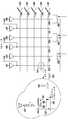
도 3은 디스플레이 디바이스의 상부 표면(top surface)에 인접하는 TFT LCD 디스플레이 매트릭스의 일부의 실시예를 나타낸 도면으로, 여기서 게이트 드라이버들과 여기 스위치들(excitation switches)이 컬럼 라인들 상에 있으며 센싱 라인들은 하나 걸러 하나씩의(alternating) 칼럼 라인들임.
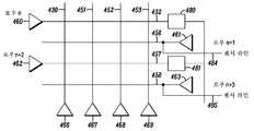
도 4는 게이트 드라이버들이 각각 하나 걸러 하나씩의 로우(row) 라인들 상에 인터리빙되고(interleaved), 여기 스위치들이 홀수 로우 라인들 상에 있으며 센싱 라인들이 짝수 로우 라인들 상에 있는 다른 실시예를 나타낸 도면.
도 5는 수신된 션트 검출에 대한, 디스플레이 및 여기 출력의 타이밍도.
도 6은 센스 라인들이 하나의 방향, 예를 들면 x-방향으로 스캔하고 그 후 다른 방향, 즉 y-방향으로 스캔할 수 있는 터치 센스 알고리즘을 나타낸 도면.1 shows one pixel of a Low Temperature Polysilicon Thin Film Transistor (LTPS TFT) display that includes an inverted bottom gate structure with the bottom gate structure flipped and now the gate facing outward.
2 illustrates a portion of a display device and an object such as a finger or a stylus.
3 illustrates an embodiment of a portion of a TFT LCD display matrix adjacent to a top surface of a display device, wherein gate drivers and excitation switches are on column lines and sensing lines Are every other column line.
FIG. 4 shows another embodiment where the gate drivers are interleaved on every other row line, each of which has excitation switches on odd row lines and sensing lines on even row lines. drawing.
5 is a timing diagram of a display and excitation output for received shunt detection.
FIG. 6 illustrates a touch sense algorithm in which sense lines can scan in one direction, eg x-direction, and then in another direction, ie y-direction. FIG.
얇은 디자인의 터치 스크린에서, 특히, 디스플레이 휘도의 감소를 방지하는 것이 이로울 것이다. 또한, 더 작고 더 얇은 디바이스들에서 새로운 특성들을 추가하고 현재의 특성들에 대해 개선할 때 더 적은 하드웨어 및 소프트웨어 컴포넌트들을 포함하는 것이 이로울 것이다. 특히, 디바이스 크기 및/또는 복잡도가 실질적으로 증가되지 않도록, 가능하다면 최소의 추가의 하드웨어 또는 소프트웨어 컴포넌트들을 사용하여, 디바이스의 이미 일부로 되어 있는 컴포넌트들을 재사용하는 것이 이롭다.In a touch screen of thin design, it would be particularly advantageous to prevent a decrease in display brightness. It would also be beneficial to include fewer hardware and software components when adding new features and improving on current features in smaller and thinner devices. In particular, it is advantageous to reuse components that are already part of the device, using minimal additional hardware or software components, if possible, so that the device size and / or complexity is not substantially increased.
터치 스크린 디바이스들과, 터치 스크린 디바이스의 표면 근처의 물체를 센싱하는 방법들이 개시된다. 이하에 상세하게 기술되는 바와 같이, 박막 트랜지스터 액정 디스플레이(TFT)가 역 바텀 게이트 구조체가 되는, 즉 게이트가 외부로 향하는 바텀 게이트 구조체를 갖는 일반적인 TFT 스택업(stack-up)을 뒤집음으로써(flipping), 이하에 상세하게 기술되는 바와 같이, 용량성 센서가 디스플레이 전자 장치 내에 통합된다. 따라서, 게이트 구조체는 디스플레이의 상부(top) 근처에 있으며, 게이트 드라이브 라인들은, 디스플레이 라인들로서의 그들의 기능에 추가하여 여기 라인들(excitation lines)로서 재사용된다. 따라서, 여기 라인들은 여기(excitation)를 드라이빙(driving)하여, 디스플레이 디바이스의 표면에서 유도 전계(induced electric field)를 생성한다. 또한, 센서 신호들이 디바이스 제어기에 입력되어 디스플레이 디바이스의 표면에서의 물체의 위치를 판정하도록 다른 라인들이 센서 라인들로서 사용된다. 따라서, 여기 라인들이 스캐닝되어 손가락 또는 다른 물체의 존재를 검출한다. 역 바텀 게이트 구조체가 되도록 일반적인 TFT 스택업을 뒤집고 전술한 바와 같이 하드웨어를 재사용할 때, 디스플레이와 이에 따른 디바이스의 두께에는 영향이 미치지 않는다.Touch screen devices and methods of sensing an object near the surface of the touch screen device are disclosed. As described in detail below, the thin film transistor liquid crystal display (TFT) becomes an inverted bottom gate structure, i.e., flipping a typical TFT stack-up with the gate facing outwards. ), As described in detail below, a capacitive sensor is integrated into the display electronics. Thus, the gate structure is near the top of the display and the gate drive lines are reused as excitation lines in addition to their function as display lines. Thus, the excitation lines drive excitation, creating an induced electric field at the surface of the display device. Also, other lines are used as the sensor lines to input sensor signals to the device controller to determine the position of the object on the surface of the display device. Thus, excitation lines are scanned to detect the presence of a finger or other object. When inverting a typical TFT stackup to be an inverted bottom gate structure and reusing hardware as described above, there is no effect on the thickness of the display and thus the device.
일반적으로, 디스플레이 디바이스에서, 디스플레이 출력을 생성하도록 복수의 칼럼 라인들이 구성되며, 디스플레이 출력을 생성하도록 복수의 로우 라인들이 구성된다. 이하에 상세하게 설명되는 바와 같이, 일 실시예에서, 칼럼 라인들 혹은 로우 라인들의 적어도 서브셋(subset)이 여기 라인들로서 구성되며, 서브셋 각각은 여기 출력을 갖는 드라이버를 포함한다. 또한, 칼럼 라인들 혹은 로우 라인들의 적어도 서브셋은, 센서 출력 라인들에 결합되는 센서 입력을 갖는 드라이버들을 포함하는 센스 라인들이다. 이러한 방식으로, 여기 출력을 갖는 여기 소스 드라이버는 디스플레이 디바이스의 표면 상에 혹은 표면 위에 전계를 유도한다. 센싱 캐패시턴스의 션트 방법은, 손가락 또는 그 밖의 다른 어떤 접지된 물체가 전계로 간섭받는 경우, 전계 라인들의 일부가 접지로 션트되고, 수신기로서 작동하는 센서 라인들에 도달하지 않는 것을 제공한다. 따라서, 수신기에서 측정되는 총 캐패시턴스는, 물체가 유도 전계 근처에 가까이 갈 때 감소한다. 전술한 디스플레이 디바이스에서는, 디스플레이 휘도가 유지되며, 간략화된 센싱 알고리즘이 존재하거나 혹은 제한적인 컬러 스킴들을 요구하지 않는다. 터치 스크린 특성은, 예를 들어 디스플레이 메뉴 조작 시에, 그리고 모바일 통신 디바이스 뿐만 아니라 그 밖의 다른 유형의 전자 디바이스들에서 게임을 할 때 사용자의 경험을 향상시킬 수 있다.In general, in a display device, a plurality of column lines is configured to generate a display output, and a plurality of row lines are configured to generate a display output. As described in detail below, in one embodiment, at least a subset of column lines or row lines are configured as excitation lines, each subset including a driver having an excitation output. Also, at least a subset of column lines or row lines are sense lines that include drivers having a sensor input coupled to sensor output lines. In this way, an excitation source driver with an excitation output induces an electric field on or over the surface of the display device. The shunt method of sensing capacitance provides that when a finger or some other grounded object interferes with the electric field, some of the electric field lines are shunted to ground and do not reach the sensor lines acting as receivers. Thus, the total capacitance measured at the receiver decreases as the object nears the induction field. In the above-described display device, the display brightness is maintained, and a simplified sensing algorithm does not exist or require limited color schemes. Touch screen characteristics can enhance the user's experience, for example, when operating display menus and when playing games on mobile communication devices as well as other types of electronic devices.
본 개시물은, 본 발명에 따른 다양한 실시예들을 제조하고 사용하는 최상의 모드들을 가능한 방식(enabling fashion)으로 설명하기 위해 제공된다. 본 개시물은 또한, 임의의 방식으로 본 발명을 제한하기 보다는, 본 발명의 원리들 및 그 이점들에 대한 이해와 인식을 향상시키도록 제공된다. 본 발명의 바람직한 실시예들이 본원에 예시되고 설명되지만, 본 발명이 이에 한정되는 것이 아님은 명백하다. 이하의 특허청구범위에 의해 정의되는 바와 같은 본 발명의 정신 및 범주로부터 벗어나지 않고 본 개시물의 이점을 갖는 본 기술 분야에 통상의 지식을 가진 자에게 수많은 변경물, 수정물, 변형물, 대체물, 및 등가물이 발생될 것이다. 제1 및 제2, 위 및 아래 등과 같은 관련 용어들이 존재한다면, 그 용어들의 용도는, 하나의 엔티티 또는 액션을, 임의의 실제적인 이러한 관계 혹은 이들 엔티티들 또는 액션들 간의 순서를 반드시 필요로 하거나 암시하지 않고, 다른 엔티티 혹은 액션과 단지 구별하는데에만 이용됨을 알 것이다.This disclosure is provided to explain in an enabling fashion the best modes of making and using various embodiments in accordance with the present invention. The present disclosure is also provided to enhance understanding and appreciation for the principles and advantages of the present invention, rather than limiting the invention in any manner. While preferred embodiments of the invention are illustrated and described herein, it is obvious that the invention is not so limited. Numerous variations, modifications, variations, substitutions, and alterations to those skilled in the art having the benefit of this disclosure without departing from the spirit and scope of the invention as defined by the following claims, and Equivalents will be generated. If there are related terms such as first and second, up and down, then the use of those terms necessarily requires one entity or action, or any actual such relationship or order between these entities or actions, or It will be appreciated that it is used only to distinguish it from other entities or actions, without implying that.
적어도 일부 신규한 기능 및 신규한 원리들이 소프트웨어 프로그램 혹은 인스트럭션들, 및 애플리케이션 특정 IC와 같은 집적 회로(IC)로 구현될 수 있다. 본 발명에 따른 원리들 및 개념들을 모호하게 하는 임의의 위험성을 최소화하고 간결하게 하기 위해, 이러한 소프트웨어 및 IC(존재하는 경우에 한함)의 설명은, 바람직한 실시예들 내의 원리들 및 개념들에 따른 필수 사항으로 제한된다.At least some new functionality and novel principles may be implemented in an integrated circuit (IC), such as a software program or instructions, and an application specific IC. In order to minimize and concise any risk of obscuring the principles and concepts according to the invention, the description of such software and IC (if present) is in accordance with the principles and concepts in the preferred embodiments. Limited to required.
도 1은 역 바텀 게이트 구조체(즉, 바텀 게이트 구조체가 뒤집혀져서 게이트가 이제 외부로 향하고 있음)를 포함하는 저온 폴리실리콘 박막 트랜지스터(LTPS TFT) 디스플레이(100)의 하나의 픽셀을 나타낸 도면이다. 위에서 간략하게 설명한 바와 같이, 따라서, 게이트 구조체는 디스플레이의 상부 근처에 있으며, 디스플레이의 상부 근처에 또한 있는 게이트 드라이브 라인들이 여기(excitation)를 드라이빙하는 데에 재사용된다. 드라이버들에 따라 디바이스 제어기에 센서 신호들이 입력된다. 전술한 바와 같은 션트 방법에 대한 센싱 및 여기를 위해, 일 실시예에서, 몇몇 라인들마다, 그리고 몇몇 칼럼들마다 아날로그 대 디지털 변환(ADC; analog-to-digital conversions)이 행해지도록 하드웨어가 LTPS TFT에 추가될 수 있다. ADC들은 단지 몇몇 로우들마다, 혹은 몇몇 칼럼들마다 행해질 수도 있으며, 양쪽 모두가 아닐 수도 있다.FIG. 1 shows one pixel of a low temperature polysilicon thin film transistor (LTPS TFT)
용량성 센싱 디스플레이 구조체는, 트랜지스터들의 매트릭스를 포함하며, 이들 중 하나의 트랜지스터(102)가 도 1에 도시되어 있다. 픽셀로부터의 빛은 백라이트에 의해 생성되며, 예를 들어, CLC(Cholesteric Liquid Crystal) 물질(104)에 걸쳐 있는 트위스트형 네마틱 크리스털(twisted nematic crystal)(103)을 통과할 수 있는데, 이 CLC 물질(104)은 공통 전극(106) 및 픽셀 전극(108)에 결합되어 있으며, 빛은, 유리일 수 있는 상부 투명 기판(110)을 빠져 나간다. 투명 기판(110)에 인접하여 블랙 매트릭스 층이 놓일 수 있다. 블랙 매트릭스 층은, 예를 들면, 바텀 게이트 구조체에서 사용되는 반사성 Cr 층을 대신하는 CrOx 층일 수 있다. 통상적인 블랙 디스플레이에서, 블랙 매트릭스 층은 보여지지 않을 수 있다. 예를 들어 Cr 층일 수 있는 반사성 층(114)은 블랙 매트릭스 층의 반대편에 있다. 반사성 층(114)은, 바텀 게이트 구조체에서, 바텀 게이트 구조체에서 사용되는 블랙 매트릭스를 대신하는 곳에 위치된다. 게이트(116) 및 그 소스(118) 및 드레인(120)은, 디스플레이 디바이스 분야에서 알려진 방식으로 동작한다. 데이터 버스 라인 혹은 칼럼 드라이브 라인(122) 및 게이트 드라이브(여기에는 도시되지 않음)와, 용량성 저장 캐패시터(124)에 대해서는 이하에서 보다 상세히 설명할 것이다.The capacitive sensing display structure includes a matrix of transistors, of which one
이하에 보다 상세히 설명되는 바와 같이, 역 바텀 게이트 구조체가 되도록 가능하게는 최소의 추가의 하드웨어를 포함하는 바텀 게이트 구조체의 전술한 재배치 및 변경에 의해, 디스플레이의 칼럼 라인들 및 로우 라인들이, 터치 스크린의 표면인 투명 기판에 실질적으로 인접하게 된다. 이러한 방식으로, 디스플레이 출력을 생성하도록 구성되는 복수 개의, 칼럼 라인들 및 로우 라인들 중 적어도 한 쪽이, 터치 스크린 디바이스의 표면인 상부 투명 기판(110)의 표면에 인접한 유도 전계를 생성하기 위한 여기 출력을 제공하는 드라이버를 포함한다. 또한, 전술한 역 바텀 게이트 구조체에 의해, 디스플레이 출력을 생성하도록 구성되는 복수 개의, 로우 라인들 및 칼럼 라인들 중 적어도 한쪽이, 센서 출력 라인들에 결합되는 센서 입력을 갖는 드라이버들을 포함한다. 센스 라인들은, 터치 스크린 디바이스의 표면에 인접한 유도 전계에 변화가 있는지 여부를 센싱하고, 적어도 하나의 센서 출력 라인을 통해 용량성 센싱 신호를 제어기(이하에 도시됨)에 송신하도록 구성된다.As described in more detail below, column lines and row lines of the display are subject to the touch screen by the foregoing relocation and modification of the bottom gate structure, possibly including a minimum of additional hardware to be an inverted bottom gate structure. The substrate is substantially adjacent to the transparent substrate. In this manner, at least one of the plurality of column lines and row lines configured to generate a display output is excited to generate an induction field adjacent to the surface of the upper
도 2는 디스플레이 디바이스(200)의 일부와, 손가락 혹은 스타일러스(226)와 같은 물체(226)를 도시한다. 투명 기판(210)일 수 있는 디바이스(200)의 표면은, 여기를 위한 칼럼 라인(230)을 포함하는 인쇄 회로 기판(PCB) 층 1과, 센스 라인(도 3 참조)에 결합된 PCB 층(232)에 인접해 있다. 칼럼 라인(230)은, 표면(210)에서 혹은 표면(210) 위에 유도 전계(236)를 생성하기 위한 여기 출력(234)을 갖는 드라이버를 포함한다. 전술한 바와 같이, 센싱 캐패시턴스의 션트 방법은, 손가락 혹은 소정의 다른 접지된 물체(226)가 전계(236)로 방해받을 때, 이 전계 라인들의 일부, 이 예에서는 전계 라인들(238, 240, 242)이 접지로 션트되며, 수신기로서 동작하는, 센서 라인(232)과 같은 센서 라인들에 도달하지 않는 것을 제공한다. 따라서, 유도 전계에 가까이 물체가 다가갈 때, 수신기에서 측정된 총 캐패시턴스를, Σ-δ ADC(Sigma-delta analog-to-digital converter)(244)가 감소시킨다. 센서 라인(232)에서 측정되는 전계 라인들(236)은 ADC(244)에 의해 디지털 도메인으로 변환(translate)된다. ADC(244)는, 디스플레이 디바이스의 제어기(246)에 데이터를 전송하는 것으로 도시되어 있다. 센서 출력 라인들, 예를 들면 센서 라인(232)과 통신하는 제어기(246)는, 용량성 센싱 신호를 수신하고, 유도 전계 내에 물체가 들어오는 것을 판정하도록 구성된다. 위치를 판정하기 위한 계산은, 센서 라인(232)이 그 센서 출력 라인(248)을 통해 용량성 센싱 신호를 제어기(246)에 송신하는 것에 기초한 것일 수 있다.2 shows a portion of
도 3은 전술한 바와 같이 디스플레이 디바이스의 상부 표면에 인접한 TFT LCD 디스플레이 매트릭스(350)의 일부를 나타낸 도면이다. 다른 바텀 게이트 구조체는 뒤집혀서, 추가의 하드웨어를 포함하는 변경 및 재배치에 의해 역 바텀 게이트 구조체가 되기 때문에, 칼럼 라인들 및 로우 라인들은 상부 투명 기판(110)(도 1 참조)에 인접하며, 이에 따라 터치 스크린 디스플레이 디바이스(200)(도 2 참조)의 표면 근처에 있게 된다. 도 3에서, 게이트 드라이버들 및 여기 스위치들은 칼럼 라인들 상에 있으며, 센싱 라인들은 하나 걸러 하나씩의(alternating) 칼럼 라인들 상에 있다. 칼럼 라인들(330, 352, 354)은, 유도 전계에 대한 여기 소스들로서 작용하며, 칼럼 라인들(351, 353, 355)은 센서 라인들(372, 373, 374)에 결합된 센서들로서 작용하여 표면 근처의 물체의 위치를 판정한다. 도 3에 도시된 칼럼 라인들이 여기 소스 및 센서들로서 작용하는 반면, 로우 라인들(332, 356, 357, 358, 359)은 (도 4에 대하여 설명한 바와 같이) 여기 소스 및 센스 라인들 양쪽 모두로서 작용할 수 있음을 알 것이다. 또한, 여기 및 센싱 양쪽 모두는, 임의의 적절한 구성의 칼럼 라인들 및 로우 라인들 양쪽 모두에 의해 달성될 수 있다. 전술한 드라이버들 및 센스 라인들의 구성은, 무엇보다도 특히, 디바이스의 다른 컴포넌트들과 그들의 배치의 편리성에 따라 달라질 수 있다.3 shows a portion of a TFT LCD display matrix 350 adjacent the top surface of the display device as described above. Since the other bottom gate structure is inverted to become an inverted bottom gate structure by modifications and rearrangements involving additional hardware, the column lines and row lines are adjacent to the top transparent substrate 110 (see FIG. 1), thus The surface of the touch screen display device 200 (see FIG. 2). In FIG. 3, the gate drivers and the excitation switches are on column lines and the sensing lines are on alternating column lines.
로우들은 라인 당 하나씩, 게이트 드라이버들(361, 362, 363, 364, 365)을 포함하는 것으로 도시되어 있다. 칼럼들은, 서브 픽셀(sub-pixel) 당 하나씩일 수 있는 칼럼 드라이브 라인들(366, 367, 368, 369, 370, 371)을 포함하는 것으로 도시되어 있다. 일반적으로, 서브 픽셀 데이터는, 한번에 3의 배수로(R, G 및 B) 전송된다. 따라서, 이 도 3에 도시된 매트릭스는 일반적인 사용 경우가 아니다. 센스 라인들(372, 373, 374)은 용량성 센싱 신호 데이터를 제어기(246)(도 2 참조)에 송신하여, 유도 전계의 변화를 알아내어서(characterize), 적어도 하나의 용량성 센싱 신호에 기초하여 터치 스크린 디바이스의 표면 근처에 물체가 있는지를 판정할 수 있다.The rows are shown to include
도 3의 풍선 모양 내에 도시된 칼럼 라인들 및 센스 라인들의 교차부(375)에서, 도 1에 도시된 바와 같은 상부 구조체 TFT는, 게이트 드라이브, 예를 들면, 게이트 드라이브(361) 및 칼럼 드라이브 라인(355)과 통신하는 저장 캐패시터(312) 및 CLC(303)를 포함할 수 있다. 게이트 드라이버(361)는, 예를 들면, 구형파(376)에 따라 하나의 로우를 드라이빙할 수 있다. 칼럼 드라이브 라인(371)은, 특히 디스플레이가 래스터 스캔으로서 동작할 수 있기 때문에, 시간 t에 따라 활성 및 비활성이 되는 칼럼 데이터(377)를 드라이빙할 수 있다.At the
전계 라인들(236)(도 2 참조)을 포함하는 전계를 유도하기 위한 여기 신호(378)는, 일반적인 칼럼 주파수에 비하여 고주파수일 수 있다. 스위치들(380, 381, 382)은 칼럼 라인들(330, 352, 354) 각각에 결합되는 것으로 도시되어 있다. 여기 신호(378)를 처리하기 위한 스위치들은, 예를 들면, 용량성 커플링, 다이오드들이거나, 혹은 전기적으로 스위칭될 수 있다. 여기(excitation)의 커플링은, 이들이 활성이 아닐 때 칼럼 라인들(330, 352, 354)에서 발생될 수 있으며, 칼럼 데이터를 인접한 칼럼들에 결합시키지 않도록 분리(isolation)를 제공하는 것이 바람직하다.The
도 4는, 게이트 드라이버들(460, 461, 462, 463)이 대안의 로우 라인들(432, 456, 457, 458) 상에서 각각 인터리빙되고 여기 스위치들(480, 481)이 홀수 로우 라인들 상에 있으며 센싱 라인들(484, 485)이 짝수 로우 라인들 상에 있는 다른 실시예를 도시한다. 이 설명에서의 로우 라인들(432, 456, 457, 458)과 도 5의 로우 라인들은 로우 n, 로우 n+1, 로우 n+2 및 로우 n+3으로 각각 칭해진다. 스위치들(480, 481) 및 센스 라인들(372, 373, 374)(도 3 참조)과 같은 컴포넌트들의 위치는, 칼럼 라인 및 로우 라인 매트릭스에 대해 상대적인 임의의 적절한 위치에 있을 수 있고 임의의 적절한 비율일 수 있음을 알 것이다. 도 3에서처럼, 도 4는 칼럼 라인들(430, 451, 452, 453) 및 칼럼 드라이브 라인들(466, 467, 468, 469)을 나타낸다. 도 3을 참조하여 언급한 바와 같이, 라인(466)과 같은 칼럼 드라이브 라인은, 시간 t에 따라 활성 및 비활성으로 되는 칼럼 디스플레이 데이터(377)를 드라이빙할 수 있다.4 shows that
도 5는 수신된 션트 검출에 대한 디스플레이 및 여기 출력의 타이밍도이다. 도 5는, 로우 n+1의 중단 기간(dormant period) 동안 로우 n이 로우 n+1을 여기시키는 것을 나타낸다. 로우 n+2는 또한 센싱 로우 n+1을 여기시킬 수 있다. 이는 로우 n+3에 대해서도 동일하게 적용된다. 로우 라인(532) 상에 도시된 파형(586)은 칼럼 주파수에 비해 고주파수의 동일한 타입의 여기 신호(378)(도 3 참조)를 포함한다. 이 예에서, 로우 라인들과 통신하는 제어기(246)(도 2 참조)는 또한, 대안적으로, 로우 라인(532)으로 하여금, 시변(time varying) 유도 전계 및 디스플레이 출력을 생성하게 하도록 구성된다. 즉, 디스플레이 신호가 오프(off)일 때, 여기 신호는 온(on)이다. 여기 출력을 갖는 스위치(480)와 통신하는 드라이버(460)(도 4 참조)는, 디스플레이 신호가 오프(off)일 때, 작은 진폭 및 고주파수의 여기에 의해 시변 유도 전계를 유발한다.5 is a timing diagram of a display and excitation output for received shunt detection. 5 shows that row n excites row n + 1 during the dormant period of row n + 1. Row n + 2 may also excite sensing row n + 1. The same applies to row n + 3.
로우 n+1은, 여기 파형(586)과 교대적으로, 전술한 바와 같이 로우(556)에 대한 디스플레이 파형(587)을 나타낸다. 화살표(588)는, 여기 파형(excitation waveform)(586) 아래에, 이 예에서는 동시에 발생하는 것으로 션트 차지(shunt charge)(589)가 도시되어 있음을 나타낸다. 전술한 바와 같이, 션트 차지(589)는, 손가락(226) 또는 다른 물체가 전계(236)에 의해 간섭되고 전계 라인들의 일부 혹은 전부가 접지로 션트되고 수신기에 도달하지 않을 때 도 2에 도시된 바와 같이 발생할 수 있다. 화살표(590)는, 션트 차지(591)가, 이 예에서, 동시에 발생하는 것으로, 로우(557)에 대한 여기 파형(592) 위에 도시됨을 나타낸다. 유사하게, 화살표(593)는, 션트 차지(594)가, 여기 파형(592) 아래에, 이 예에서는, 동시에 발생하는 것으로 도시되어 있음을 나타낸다. 로우 라인(558), 즉 로우 n+3 상에서, 디스플레이 파형(595) 및 다른 션트 차지(596)가 도시되어 있다. 로우 및 칼럼 라인들의 매트릭스는, 이 예에 비하여 상당히 광범위할 수 있음을 알 것이다. 예를 들면, 20-30 개의 로우들이, 전술한 터치 스크린 디스플레이 위에서 하나의 손가락으로 덮여질 수 있다. 날카로운 스타일러스는 단지 하나의 로우만을 덮을 수도 있다.Row n + 1 alternates with
도 6은, 센스 라인들이 하나의 방향, 예를 들면 x-방향으로 스캐닝하고 그 후 다른 방향, 즉, y-방향으로 스캐닝할 수 있는 터치 센스 알고리즘을 나타낸다. 터치 스크린 상의 물체의 위치를 판정하기 위한 알고리즘에 따라, 스캔은 x-방향으로의 스캐닝을 포함할 필요가 없을 수도 있다. 도 5를 참조한 설명에서, 개시 블럭 621에서 시작하면, 파형들(587, 595)(도 5 참조)에 의해 도시된 바와 같이 디스플레이 출력이 생성된다. 유도 전계는, 디스플레이 출력을 생성할 때와는 다른 시간에, 터치 스크린 디바이스(236)(도 2 참조)의 표면 위에 생성된다. 전술한 바와 같이, 여기의 편차(deviation)는, 생성되는 것으로부터의 수신된 전계 라인들의 델타(델타는 제1 값과 제2 값 사이의 차에 대한 수학적 라벨(mathematical label)임)를 판정할 수 있다. 짝수 라인들, 이 경우에는 로우 n+1 및 로우 n+3 상의 센싱은 칼럼 드라이브 카운트를 이용하여 x-위치를 판정한다. 따라서, 이 예에서는, 로우들이 스캐닝되어(단계 623), y-방향 물체 위치를 검출한다(단계 625). y-방향 위치를 갖고 있는 것으로 물체가 검출되지 않는 경우, 스캐닝(단계 623)을 계속한다. 물체가 y-방향 위치를 갖는 것으로 검출되는 경우, 칼럼 스캔(단계 627)이 라스터 스캔에서 일부 혹은 모든 프레임에 대해 행해져서 x-방향 물체 위치를 획득하게 된다. 디스플레이 스크린에서 플리커(flicker)를 방지하기 위해서는, 칼럼 스캔(단계 627)이 프레임을 하나 걸러 하나씩 혹은 그 이상으로 행해질 수 있다. 용량성 센싱 신호를 나타내는 x-방향에 대한 데이터 및 y-방향 데이터는 제어기(246)에 송신되어서(단계 629), 적어도 하나의 용량성 센싱 신호에 기초하여 터치 스크린 디바이스 표면 근처에 물체가 있는 것을 판정하기 위해 유도 전계의 변화를 알아낼 수 있게 된다.6 illustrates a touch sense algorithm in which sense lines can be scanned in one direction, for example the x-direction, and then in the other direction, ie the y-direction. Depending on the algorithm for determining the position of the object on the touch screen, the scan may not need to include scanning in the x-direction. In the description with reference to FIG. 5, beginning at
전술한 바와 같은 칼럼 라인들 및 로우 라인들은, 표면(즉, 터치 스크린 디스플레이 디바이스의 표면)으로서 갖는 투명 기판에 인접해 있기 때문에, 전술한 바와 같은 터치 스크린 디스플레이는 유리 층들 사이에 구현되며, 이에 따라 유리 두께와는 무관할 수 있다. 디바이스들, 특히, 모바일 통신 디바이스들은 점점 더 소형 박형화되고 있기 때문에, 전술한 터치 스크린은 많은 폼 팩터들과 호환가능하게 될 수 있다. 또한, 전술한 얇은 디자인의 터치 스크린은, 특히, 디스플레이 휘도의 감소를 방지할 수 있다. 전술한 터치 스크린은 또한 이롭게도, 디바이스의 이미 일부인 컴포넌트들을 재사용한다. 전술한 터치 스크린에서, 가능하게는 최소의 추가의 하드웨어 혹은 소프트웨어 컴포넌트들을 가지고 역 바텀 게이트 구조체가 되도록 바텀 게이트 구조체를 뒤집어서, 디바이스 크기 및/또는 복잡도가 실질적으로 증가되지 않게 하는 것은 또한 비용 이점을 제공할 수 있다.Since the column lines and row lines as described above are adjacent to the transparent substrate having as a surface (ie, the surface of the touch screen display device), the touch screen display as described above is implemented between the glass layers and thus It can be independent of glass thickness. As devices, especially mobile communication devices, are becoming smaller and thinner, the touch screen described above can be made compatible with many form factors. In addition, the above-described thin design touch screen can, in particular, prevent a decrease in display brightness. The aforementioned touch screen also advantageously reuses components that are already part of the device. In the aforementioned touch screen, it is also a cost advantage to invert the bottom gate structure to be an inverted bottom gate structure, possibly with minimal additional hardware or software components, so that the device size and / or complexity is not substantially increased. can do.
본 개시물은, 진정한 의도된 공정한 범주 및 그 정신을 제한하기보다는, 본 기술에 따른 다양한 실시예들을 만들어내고 사용하는 방법을 설명하기 위한 것이다. 전술한 설명은, 철저한 것이거나 혹은 개시된 정확한 형태로 제한되는 것을 의도하는 것은 아니다. 전술한 개시물의 관점에서 변경 혹은 변형이 가능하다. 개시된 기술의 원리 및 그 실제 적용의 최상의 예시를 제공하고, 본 기술 분야에 통상의 지식을 가진 자가, 고려되는 특정 사용에 적합하게 되는 다양한 실시예들과 다양한 변형들에서 본 기술을 이용하도록 하기 위해 실시예(들)가 선택되었고 설명되었다. 이러한 모든 변경들 및 변형들은, 이들이 정당하게, 합법적으로, 그리고 공정하게 자격이 주어지는 범위에 따라 해석될 때, 특허를 위한 본 출원의 계류 동안 수정될 수 있는 첨부된 특허청구범위, 및 그 모든 등가물에 의해 결정되는 본 발명의 범주 내에 있다.This disclosure is intended to explain how to fashion and use various embodiments in accordance with the present technology, rather than to limit the true intended fair scope and spirit thereof. The foregoing description is not intended to be exhaustive or to be limited to the precise form disclosed. Modifications or variations are possible in light of the above disclosure. To provide the best examples of the principles of the disclosed technology and its practical application, and to enable those skilled in the art to use the technology in various embodiments and various modifications as would be suitable for the particular use contemplated. Example (s) have been selected and described. All such changes and modifications, when interpreted in accordance with the scope to which they are duly, legally and fairly entitled, are the appended claims, and all equivalents thereof, which may be amended during the pending of this application for the patent. It is within the scope of the present invention as determined by.
Claims (20)
Translated fromKorean디스플레이 출력을 생성하도록 구성된, 복수 개의, 칼럼 라인들(column lines) 및 로우 라인들(row lines) 중 적어도 한쪽의 라인 - 상기 복수 개의, 칼럼 라인들 및 로우 라인들 중 적어도 한쪽의 라인의 적어도 서브셋(subset)이 여기 라인들(excitation lines)로서 구성되며, 상기 서브셋 각각은 여기 출력(excitation output)을 갖는 드라이버를 포함하며, 상기 서브셋은 서로 통신하여 상기 터치 스크린 디바이스의 표면에 인접한 유도 전계(induced electric field)를 생성함 -;
디스플레이 출력을 생성하도록 구성된, 복수 개의, 로우 라인들 및 칼럼 라인들 중 적어도 한쪽의 라인 - 상기 복수 개의, 로우 라인들 및 칼럼 라인들 중 적어도 한쪽의 라인의 적어도 서브셋은, 센서 출력 라인들에 결합되는 센서 입력을 갖는 드라이버들을 포함하는 센스 라인들이며, 상기 센스 라인들은, 상기 터치 스크린 디바이스의 표면에 인접한 상기 유도 전계에 변화가 있는지를 센싱하고 적어도 하나의 센서 출력 라인을 통하여 용량성 센싱 신호를 송신하도록 구성됨 -; 및
상기 센서 출력 라인들과 통신하며, 적어도 하나의 용량성 센싱 신호를 수신하며, 센서 입력을 갖는 드라이버를 포함하는 적어도 하나의 센스 라인 중 어느 것이 그 센서 출력 라인을 통하여 용량성 센싱 신호를 송신하는지에 기초하여 상기 유도 전계 내에 물체(object)가 들어왔는지를 판정하도록 구성된 제어기
를 포함하는 터치 스크린 디바이스.A touch screen device having a surface,
At least one of a plurality of column lines and row lines, configured to generate a display output, at least a subset of at least one of the plurality of column lines and row lines (subset) is configured as excitation lines, each of the subsets includes a driver having an excitation output, the subsets communicating with each other to induce an induced field adjacent to the surface of the touch screen device generate electric field);
At least one of a plurality of row lines and column lines configured to generate a display output, at least a subset of at least one of the plurality of row lines and column lines coupled to sensor output lines Sense lines comprising drivers having a sensor input, wherein the sense lines sense whether there is a change in the induction field adjacent to the surface of the touch screen device and transmit a capacitive sensing signal through at least one sensor output line Configured to; And
In communication with the sensor output lines, receiving at least one capacitive sensing signal, and at least one sense line comprising a driver having a sensor input transmits the capacitive sensing signal through the sensor output line. A controller configured to determine whether an object enters into the induced electric field based on the
Touch screen device comprising a.
상기 터치 스크린 디바이스의 표면과, 상기 복수의 칼럼 라인들 및 상기 복수의 로우 라인들 사이의 투명 기판을 더 포함하는 터치 스크린 디바이스.The method of claim 1,
And a transparent substrate between the surface of the touch screen device and the plurality of column lines and the plurality of row lines.
상기 복수의 칼럼 라인들의 서브셋의 여기 출력을 갖는 드라이버들은 실질적으로 상기 투명 기판에 인접해 있는 터치 스크린 디바이스.The method of claim 2,
Drivers having an excitation output of the subset of the plurality of column lines are substantially adjacent to the transparent substrate.
블랙 매트릭스 층이 상기 투명 기판에 인접하여 있는 터치 스크린 디바이스.The method of claim 2,
And a black matrix layer is adjacent the transparent substrate.
상기 블랙 매트릭스 층의 반대편의 반사 층을 더 포함하는 터치 스크린 디바이스.The method of claim 2,
And a reflective layer opposite the black matrix layer.
상기 용량성 센싱 신호는, 상기 터치 스크린 디바이스의 표면에 인접한 유도 전계의 편차(deviation)를 나타내는 터치 스크린 디바이스.The method of claim 1,
And the capacitive sensing signal indicates a deviation of an induction field adjacent to a surface of the touch screen device.
상기 칼럼 라인들 및 상기 로우 라인들 중 적어도 한쪽의 라인과 통신하는 상기 제어기는 또한, 상기 칼럼 라인들 및 로우 라인들 중 적어도 한쪽의 라인으로 하여금 대안적으로 시변(time varying) 유도 전계 및 디스플레이 출력을 생성하게 하도록 구성되는 터치 스크린 디바이스.The method of claim 1,
The controller in communication with at least one of the column lines and the row lines also causes at least one of the column lines and the row lines to alternately time varying induction electric field and display output. And to generate the touch screen device.
여기 출력을 갖는 드라이버는, 작은 진폭 및 높은 주파수의 여기에 의해 상기 시변 유도 전계를 유발하는 터치 스크린 디바이스.The method of claim 7, wherein
A driver having an excitation output causes the time-varying induction field to be caused by small amplitude and high frequency excitation.
디스플레이 출력을 출력하도록 구성된, 복수 개의, 로우 라인들 및 칼럼 라인들 중 적어도 한쪽의 라인 - 상기 복수 개의, 로우 라인들 및 칼럼 라인들 중 적어도 한쪽의 라인의 적어도 서브셋은 여기 출력을 갖는 드라이버를 포함하며, 상기 복수 개의, 로우 라인들 및 칼럼 라인들 중 적어도 한쪽의 라인의 적어도 서브셋은 센서 출력 라인들에 결합된 센서 입력을 갖는 드라이버들을 포함하며, 여기 출력을 갖는 드라이버를 포함하는 라인들은, 센서 입력을 갖는 드라이버를 포함하는 라인들과는 상이함 -; 및
상기 센서 출력 라인들과 통신하며, 적어도 하나의 용량성 센싱 신호를 수신하며, 센서 입력을 갖는 드라이버를 포함하는 적어도 하나의 센스 라인 중 어느 것이 그 센서 출력 라인을 통하여 용량성 센싱 신호를 송신하는지에 기초하여 유도 전계 내에 물체가 들어왔는지를 판정하도록 구성된 제어기
를 포함하는 터치 스크린 디바이스.A touch screen device having a surface,
At least one of a plurality of row lines and column lines configured to output a display output, wherein at least a subset of at least one of the plurality of row lines and column lines comprises a driver having an excitation output Wherein at least a subset of at least one of the plurality of row lines and column lines comprises drivers having a sensor input coupled to sensor output lines, the lines comprising a driver having an excitation output, Different from the lines containing the driver having an input; And
In communication with the sensor output lines, receiving at least one capacitive sensing signal, and at least one sense line comprising a driver having a sensor input transmits the capacitive sensing signal through the sensor output line. A controller configured to determine whether an object enters the induced electric field based on the
Touch screen device comprising a.
상기 터치 스크린 디바이스의 표면과 상기 복수의 로우 라인들 사이의 투명 기판을 더 포함하는 터치 스크린 디바이스.10. The method of claim 9,
And a transparent substrate between the surface of the touch screen device and the plurality of row lines.
센서 입력을 갖는 드라이버들은 상기 투명 기판에 인접하여 있는 터치 스크린 디바이스.The method of claim 10,
Drivers with sensor inputs are adjacent the transparent substrate.
블랙 매트릭스 층이 상기 투명 기판에 인접하여 있는 터치 스크린 디바이스.The method of claim 11,
And a black matrix layer is adjacent the transparent substrate.
상기 블랙 매트릭스 층의 반대편의 반사 층을 더 포함하는 터치 스크린 디바이스.The method of claim 11,
And a reflective layer opposite the black matrix layer.
상기 용량성 센싱 신호는, 상기 터치 스크린 디바이스의 표면에 인접한 유도 전계의 편차를 나타내는 터치 스크린 디바이스.10. The method of claim 9,
And the capacitive sensing signal indicates a deviation of an induction field adjacent to a surface of the touch screen device.
여기 출력을 갖는 드라이버는, 작은 진폭 및 높은 주파수의 여기에 의해 시변 유도 전계를 유발하는 터치 스크린 디바이스.10. The method of claim 9,
A driver having an excitation output causes a touch screen device to cause a time varying induction field by excitation of small amplitudes and high frequencies.
디스플레이 출력을 생성하는 단계;
디스플레이 출력을 생성할 때와는 다른 시간에 상기 터치 스크린 디바이스의 표면 위에 유도 전계를 생성하는 단계;
상기 유도 전계의 변화를 검출하는 단계;
상기 유도 전계의 변화를 나타내는 용량성 센싱 신호를 생성하는 단계;
상기 용량성 센싱 신호를 제어기에 송신하는 단계; 및
적어도 하나의 용량성 센싱 신호에 기초하여 상기 터치 스크린 디바이스의 표면 근처에 물체가 있는지를 판정하기 위해 상기 유도 전계의 변화를 알아내는(characterizing) 단계
를 포함하는 물체 센싱 방법.A method of sensing an object near a surface of a touch screen device,
Generating a display output;
Generating an induction field on the surface of the touch screen device at a different time than when generating a display output;
Detecting a change in the induced electric field;
Generating a capacitive sensing signal indicative of a change in the induced electric field;
Transmitting the capacitive sensing signal to a controller; And
Characterizing a change in the induced electric field to determine whether an object is near the surface of the touch screen device based on at least one capacitive sensing signal
Object sensing method comprising a.
상기 터치 스크린 디바이스는 칼럼 라인들 및 로우 라인들을 가지며, 상기 칼럼 라인들의 적어도 서브셋에 의해 상기 터치 스크린 디바이스의 표면 위에 시변 유도 전계가 생성되며,
상기 칼럼 라인들의 서브셋의 디스플레이 출력을 대안적으로(alternatively) 드라이빙(driving)하고, 상기 칼럼 라인들의 서브셋의 작은 진폭 및 높은 주파수의 여기를 드라이빙하는 단계를 더 포함하는 물체 센싱 방법.The method of claim 16,
The touch screen device has column lines and row lines, a time-varying induction field is generated on the surface of the touch screen device by at least a subset of the column lines,
Alternatively driving the display output of the subset of column lines and driving a small amplitude and high frequency excitation of the subset of column lines.
상기 터치 스크린 디바이스는 칼럼 라인들 및 로우 라인들을 가지며, 상기 로우 라인들의 적어도 서브셋에 의해 상기 터치 스크린 디바이스의 표면 위에 시변 유도 전계가 생성되며,
상기 로우 라인들의 서브셋의 디스플레이 출력을 대안적으로 드라이빙하고 상기 로우 라인들의 서브셋의 작은 진폭 및 높은 주파수의 여기를 드라이빙하는 단계를 더 포함하는 물체 센싱 방법.The method of claim 16,
The touch screen device has column lines and row lines, a time-varying induction field is generated on the surface of the touch screen device by at least a subset of the row lines,
Alternatively driving a display output of the subset of row lines and driving a small amplitude and high frequency excitation of the subset of row lines.
상기 터치 스크린 디바이스는 칼럼 라인들 및 로우 라인들을 가지며, 상기 유도 전계의 변화를 검출하는 단계는,
상기 로우 라인들의 적어도 서브셋의 적어도 하나의 로우 라인에 의해, 상기 터치 스크린 디바이스의 표면에 인접한 상기 유도 전계의 편차를 센싱하는 단계를 더 포함하는 물체 센싱 방법.The method of claim 16,
The touch screen device has column lines and row lines, and detecting the change in the induction field includes:
Sensing, by at least one row line of the at least a subset of the row lines, a deviation of the induced electric field adjacent the surface of the touch screen device.
상기 터치 스크린 디바이스는 칼럼 라인들 및 로우 라인들을 가지며, 상기 유도 전계의 변화를 검출하는 단계는,
상기 칼럼 라인들의 적어도 서브셋의 적어도 하나의 칼럼 라인에 의해, 상기 터치 스크린 디바이스의 표면에 인접한 상기 유도 전계의 편차를 센싱하는 단계를 더 포함하는 물체 센싱 방법.The method of claim 16,
The touch screen device has column lines and row lines, and detecting the change in the induction field includes:
Sensing, by at least one column line of at least a subset of the column lines, a deviation of the induced electric field adjacent the surface of the touch screen device.
Applications Claiming Priority (2)
| Application Number | Priority Date | Filing Date | Title |
|---|---|---|---|
| US11/859,997 | 2007-09-24 | ||
| US11/859,997US20090079707A1 (en) | 2007-09-24 | 2007-09-24 | Integrated capacitive sensing devices and methods |
Publications (1)
| Publication Number | Publication Date |
|---|---|
| KR20100046270Atrue KR20100046270A (en) | 2010-05-06 |
Family
ID=40471090
Family Applications (1)
| Application Number | Title | Priority Date | Filing Date |
|---|---|---|---|
| KR1020107006446ACeasedKR20100046270A (en) | 2007-09-24 | 2008-09-12 | Integrated capacitive sensing devices and methods |
Country Status (8)
| Country | Link |
|---|---|
| US (1) | US20090079707A1 (en) |
| EP (1) | EP2193428A2 (en) |
| KR (1) | KR20100046270A (en) |
| CN (1) | CN101809530A (en) |
| BR (1) | BRPI0817980A2 (en) |
| MX (1) | MX2010003237A (en) |
| RU (1) | RU2010116164A (en) |
| WO (1) | WO2009042422A2 (en) |
Cited By (1)
| Publication number | Priority date | Publication date | Assignee | Title |
|---|---|---|---|---|
| KR20140069103A (en)* | 2011-09-07 | 2014-06-09 | 시냅틱스, 인코포레이티드 | Capacitive sensing during non-display update times |
Families Citing this family (31)
| Publication number | Priority date | Publication date | Assignee | Title |
|---|---|---|---|---|
| TW200947030A (en)* | 2008-05-13 | 2009-11-16 | Tpk Touch Solutions Inc | Capacitive touch control device and method thereof |
| US9477342B2 (en) | 2008-08-26 | 2016-10-25 | Google Technology Holdings LLC | Multi-touch force sensing touch-screen devices and methods |
| US8643624B2 (en)* | 2009-03-18 | 2014-02-04 | Synaptics Incorporated | Capacitive sensing using a segmented common voltage electrode of a display |
| KR101610109B1 (en) | 2009-05-19 | 2016-04-11 | 삼성전자주식회사 | Method and Apparatus for tracking input position using E-Field Communication |
| US20110007019A1 (en)* | 2009-07-07 | 2011-01-13 | Nuvoton Technology Corporation | Systems and methods for using tft-based lcd panels as capacitive touch sensors |
| TWI428661B (en)* | 2009-11-09 | 2014-03-01 | Silicon Integrated Sys Corp | Touch display apparatus |
| CN102884496B (en)* | 2010-02-26 | 2017-06-30 | 辛纳普蒂克斯公司 | Modify demodulation to avoid interference |
| CN102193693B (en)* | 2010-03-17 | 2014-03-19 | 群康科技(深圳)有限公司 | Touch panel and differential identification method thereof |
| US9898121B2 (en) | 2010-04-30 | 2018-02-20 | Synaptics Incorporated | Integrated capacitive sensing and displaying |
| KR20130016980A (en)* | 2011-08-09 | 2013-02-19 | 삼성디스플레이 주식회사 | Display device |
| DE102011054690B4 (en)* | 2011-10-21 | 2016-05-12 | Ident Technology Ag | Electrode device for a capacitive sensor device for position detection |
| CN104380312B (en)* | 2012-02-06 | 2018-07-10 | 高通股份有限公司 | Use the system and method for electric field arrangement |
| US20130207899A1 (en)* | 2012-02-09 | 2013-08-15 | Po-Hsien Wang | Touch-sensing display device |
| KR101971147B1 (en) | 2012-04-09 | 2019-04-23 | 삼성디스플레이 주식회사 | Display device including touch sensor |
| KR101929427B1 (en) | 2012-06-14 | 2018-12-17 | 삼성디스플레이 주식회사 | Display device including touch sensor |
| JP2014021799A (en)* | 2012-07-20 | 2014-02-03 | Kyocera Display Corp | Touch panel device |
| US10073568B2 (en) | 2012-08-15 | 2018-09-11 | Synaptics Incorporated | System and method for interference avoidance for a display device comprising an integrated sensing device |
| CN102866815B (en)* | 2012-09-03 | 2015-07-01 | 北京京东方光电科技有限公司 | Capacitance type embedded touch screen and display device |
| CN103293785B (en)* | 2012-12-24 | 2016-05-18 | 上海天马微电子有限公司 | TN (twisted nematic) type liquid crystal display device and touch control method thereof |
| US9235299B2 (en) | 2013-02-06 | 2016-01-12 | Google Technology Holdings LLC | Touch sensitive surface for an electronic device with false touch protection |
| JP2014174851A (en)* | 2013-03-11 | 2014-09-22 | Japan Display Inc | Touch sensor device, display device and electronic device |
| CN103699282B (en)* | 2013-12-24 | 2016-12-07 | 华映视讯(吴江)有限公司 | Touch control display apparatus |
| US9582099B2 (en) | 2014-03-31 | 2017-02-28 | Synaptics Incorporated | Serrated input sensing intervals |
| US9501169B2 (en)* | 2014-06-27 | 2016-11-22 | Synaptics Incorporated | Acquiring multiple capacitive partial profiles with orthogonal sensor electrodes |
| CN106796467A (en)* | 2014-10-07 | 2017-05-31 | 美国亚德诺半导体公司 | The capacitance sensing of aggregation |
| US10175827B2 (en) | 2014-12-23 | 2019-01-08 | Synaptics Incorporated | Detecting an active pen using a capacitive sensing device |
| US10394391B2 (en) | 2015-01-05 | 2019-08-27 | Synaptics Incorporated | System and method for reducing display artifacts |
| US10275070B2 (en) | 2015-01-05 | 2019-04-30 | Synaptics Incorporated | Time sharing of display and sensing data |
| CN105183252B (en)* | 2015-08-13 | 2016-11-02 | 京东方科技集团股份有限公司 | An array substrate, a touch display screen, a display device, and a driving method |
| US10037112B2 (en) | 2015-09-30 | 2018-07-31 | Synaptics Incorporated | Sensing an active device'S transmission using timing interleaved with display updates |
| US10592022B2 (en) | 2015-12-29 | 2020-03-17 | Synaptics Incorporated | Display device with an integrated sensing device having multiple gate driver circuits |
Family Cites Families (8)
| Publication number | Priority date | Publication date | Assignee | Title |
|---|---|---|---|---|
| US5543590A (en)* | 1992-06-08 | 1996-08-06 | Synaptics, Incorporated | Object position detector with edge motion feature |
| US5847690A (en)* | 1995-10-24 | 1998-12-08 | Lucent Technologies Inc. | Integrated liquid crystal display and digitizer having a black matrix layer adapted for sensing screen touch location |
| US5777596A (en)* | 1995-11-13 | 1998-07-07 | Symbios, Inc. | Touch sensitive flat panel display |
| US6274887B1 (en)* | 1998-11-02 | 2001-08-14 | Semiconductor Energy Laboratory Co., Ltd. | Semiconductor device and manufacturing method therefor |
| GB0114456D0 (en)* | 2001-06-14 | 2001-08-08 | Koninkl Philips Electronics Nv | Object sensing |
| TWI245252B (en)* | 2002-07-18 | 2005-12-11 | Gigno Technology Co Ltd | LCD and the touch-control method thereof |
| JP2005322160A (en)* | 2004-05-11 | 2005-11-17 | Olympus Corp | Display device with touch panel |
| GB0412787D0 (en)* | 2004-06-09 | 2004-07-14 | Koninkl Philips Electronics Nv | Input system |
- 2007
- 2007-09-24USUS11/859,997patent/US20090079707A1/ennot_activeAbandoned
- 2008
- 2008-09-12EPEP08834247Apatent/EP2193428A2/ennot_activeWithdrawn
- 2008-09-12KRKR1020107006446Apatent/KR20100046270A/ennot_activeCeased
- 2008-09-12WOPCT/US2008/076137patent/WO2009042422A2/enactiveApplication Filing
- 2008-09-12CNCN200880108329Apatent/CN101809530A/enactivePending
- 2008-09-12MXMX2010003237Apatent/MX2010003237A/enunknown
- 2008-09-12RURU2010116164/08Apatent/RU2010116164A/enunknown
- 2008-09-12BRBRPI0817980patent/BRPI0817980A2/ennot_activeApplication Discontinuation
Cited By (2)
| Publication number | Priority date | Publication date | Assignee | Title |
|---|---|---|---|---|
| KR20140069103A (en)* | 2011-09-07 | 2014-06-09 | 시냅틱스, 인코포레이티드 | Capacitive sensing during non-display update times |
| KR101879479B1 (en)* | 2011-09-07 | 2018-07-17 | 시냅틱스 인코포레이티드 | Capacitive sensing during non-display update times |
Also Published As
| Publication number | Publication date |
|---|---|
| WO2009042422A2 (en) | 2009-04-02 |
| US20090079707A1 (en) | 2009-03-26 |
| BRPI0817980A2 (en) | 2015-04-07 |
| WO2009042422A3 (en) | 2009-06-04 |
| MX2010003237A (en) | 2010-04-21 |
| EP2193428A2 (en) | 2010-06-09 |
| CN101809530A (en) | 2010-08-18 |
| RU2010116164A (en) | 2011-11-10 |
Similar Documents
| Publication | Publication Date | Title |
|---|---|---|
| KR20100046270A (en) | Integrated capacitive sensing devices and methods | |
| US11256354B2 (en) | Sensor device and display device | |
| US11573652B2 (en) | Touch detection device and display device with touch detection function | |
| CN101937141B (en) | Touch sensor, display and electronic unit | |
| US9746956B2 (en) | Touch detector and method of driving the same, display with touch detection function, and electronic unit having plural different drive electrodes | |
| US9274653B2 (en) | Touch detection device and display device having touch sensor function | |
| US8976123B2 (en) | Display device and electronic unit | |
| CN104603725B (en) | Method and apparatus for improved input sensing using a display processor reference signal | |
| JP5178633B2 (en) | Touch sensor, display device, and electronic device | |
| US8319750B2 (en) | Sensing circuit, method of driving sensing circuit, display device, method of driving display device, and electronic apparatus | |
| US10545589B2 (en) | Touch detection device | |
| JP2007334606A (en) | Display device, display device drive device, and drive method | |
| KR20100124208A (en) | Display device and electronic unit | |
| CN102314255B (en) | Detection device and display device | |
| WO2013127051A1 (en) | Display device and touch sensing method therefor | |
| KR20210157886A (en) | Reducing display artifacts caused by a sensing signal of a proximity input device | |
| KR101419251B1 (en) | Liquid crystal display device having touch sensor and method for driving the same | |
| KR101661693B1 (en) | Method for duplexing user input for user device | |
| JP2012230471A (en) | Touch panel | |
| JP2023106247A (en) | Display device with touch panel and touch panel | |
| JP2022191080A (en) | Input detection system and detection apparatus | |
| GB2469374A (en) | A circuit for switching voltage supplies to a gate line of a touch sensitive display | |
| US12340051B2 (en) | Display panel, driving method thereof, and display device |
Legal Events
| Date | Code | Title | Description |
|---|---|---|---|
| A201 | Request for examination | ||
| PA0105 | International application | Patent event date:20100324 Patent event code:PA01051R01D Comment text:International Patent Application | |
| PA0201 | Request for examination | ||
| PG1501 | Laying open of application | ||
| N231 | Notification of change of applicant | ||
| PN2301 | Change of applicant | Patent event date:20101229 Comment text:Notification of Change of Applicant Patent event code:PN23011R01D | |
| PE0902 | Notice of grounds for rejection | Comment text:Notification of reason for refusal Patent event date:20110718 Patent event code:PE09021S01D | |
| E601 | Decision to refuse application | ||
| PE0601 | Decision on rejection of patent | Patent event date:20110929 Comment text:Decision to Refuse Application Patent event code:PE06012S01D Patent event date:20110718 Comment text:Notification of reason for refusal Patent event code:PE06011S01I |