KR20100044154A - Electric vehicle charging station and payment system - Google Patents
Electric vehicle charging station and payment systemDownload PDFInfo
- Publication number
- KR20100044154A KR20100044154AKR1020100032884AKR20100032884AKR20100044154AKR 20100044154 AKR20100044154 AKR 20100044154AKR 1020100032884 AKR1020100032884 AKR 1020100032884AKR 20100032884 AKR20100032884 AKR 20100032884AKR 20100044154 AKR20100044154 AKR 20100044154A
- Authority
- KR
- South Korea
- Prior art keywords
- charging
- charge
- electric vehicle
- terminal
- mobile phone
- Prior art date
- Legal status (The legal status is an assumption and is not a legal conclusion. Google has not performed a legal analysis and makes no representation as to the accuracy of the status listed.)
- Ceased
Links
Images


Classifications
- B—PERFORMING OPERATIONS; TRANSPORTING
- B60—VEHICLES IN GENERAL
- B60L—PROPULSION OF ELECTRICALLY-PROPELLED VEHICLES; SUPPLYING ELECTRIC POWER FOR AUXILIARY EQUIPMENT OF ELECTRICALLY-PROPELLED VEHICLES; ELECTRODYNAMIC BRAKE SYSTEMS FOR VEHICLES IN GENERAL; MAGNETIC SUSPENSION OR LEVITATION FOR VEHICLES; MONITORING OPERATING VARIABLES OF ELECTRICALLY-PROPELLED VEHICLES; ELECTRIC SAFETY DEVICES FOR ELECTRICALLY-PROPELLED VEHICLES
- B60L53/00—Methods of charging batteries, specially adapted for electric vehicles; Charging stations or on-board charging equipment therefor; Exchange of energy storage elements in electric vehicles
- B60L53/60—Monitoring or controlling charging stations
- B60L53/66—Data transfer between charging stations and vehicles
- B60L53/665—Methods related to measuring, billing or payment
- G—PHYSICS
- G06—COMPUTING OR CALCULATING; COUNTING
- G06Q—INFORMATION AND COMMUNICATION TECHNOLOGY [ICT] SPECIALLY ADAPTED FOR ADMINISTRATIVE, COMMERCIAL, FINANCIAL, MANAGERIAL OR SUPERVISORY PURPOSES; SYSTEMS OR METHODS SPECIALLY ADAPTED FOR ADMINISTRATIVE, COMMERCIAL, FINANCIAL, MANAGERIAL OR SUPERVISORY PURPOSES, NOT OTHERWISE PROVIDED FOR
- G06Q50/00—Information and communication technology [ICT] specially adapted for implementation of business processes of specific business sectors, e.g. utilities or tourism
- G06Q50/40—Business processes related to the transportation industry
- B—PERFORMING OPERATIONS; TRANSPORTING
- B60—VEHICLES IN GENERAL
- B60L—PROPULSION OF ELECTRICALLY-PROPELLED VEHICLES; SUPPLYING ELECTRIC POWER FOR AUXILIARY EQUIPMENT OF ELECTRICALLY-PROPELLED VEHICLES; ELECTRODYNAMIC BRAKE SYSTEMS FOR VEHICLES IN GENERAL; MAGNETIC SUSPENSION OR LEVITATION FOR VEHICLES; MONITORING OPERATING VARIABLES OF ELECTRICALLY-PROPELLED VEHICLES; ELECTRIC SAFETY DEVICES FOR ELECTRICALLY-PROPELLED VEHICLES
- B60L2250/00—Driver interactions
- B60L2250/16—Driver interactions by display
- B—PERFORMING OPERATIONS; TRANSPORTING
- B60—VEHICLES IN GENERAL
- B60Y—INDEXING SCHEME RELATING TO ASPECTS CROSS-CUTTING VEHICLE TECHNOLOGY
- B60Y2200/00—Type of vehicle
- B60Y2200/90—Vehicles comprising electric prime movers
- B60Y2200/91—Electric vehicles
- Y—GENERAL TAGGING OF NEW TECHNOLOGICAL DEVELOPMENTS; GENERAL TAGGING OF CROSS-SECTIONAL TECHNOLOGIES SPANNING OVER SEVERAL SECTIONS OF THE IPC; TECHNICAL SUBJECTS COVERED BY FORMER USPC CROSS-REFERENCE ART COLLECTIONS [XRACs] AND DIGESTS
- Y02—TECHNOLOGIES OR APPLICATIONS FOR MITIGATION OR ADAPTATION AGAINST CLIMATE CHANGE
- Y02T—CLIMATE CHANGE MITIGATION TECHNOLOGIES RELATED TO TRANSPORTATION
- Y02T90/00—Enabling technologies or technologies with a potential or indirect contribution to GHG emissions mitigation
- Y02T90/10—Technologies relating to charging of electric vehicles
- Y02T90/16—Information or communication technologies improving the operation of electric vehicles
Landscapes
- Engineering & Computer Science (AREA)
- Business, Economics & Management (AREA)
- Human Resources & Organizations (AREA)
- Marketing (AREA)
- Transportation (AREA)
- Health & Medical Sciences (AREA)
- Economics (AREA)
- General Health & Medical Sciences (AREA)
- Power Engineering (AREA)
- Mechanical Engineering (AREA)
- Primary Health Care (AREA)
- Strategic Management (AREA)
- Tourism & Hospitality (AREA)
- Physics & Mathematics (AREA)
- General Business, Economics & Management (AREA)
- General Physics & Mathematics (AREA)
- Theoretical Computer Science (AREA)
- Charge And Discharge Circuits For Batteries Or The Like (AREA)
Abstract
Translated fromKoreanDescription
Translated fromKorean본 발명은 핸드폰을 이용한 전기자동차 배터리 충전소용 충전시스템의 충전제어 및 과금에 관한 방식으로 충전전원 공급장치(충전제어기)와 과금(요금지불) 시스템을 연동하여 핸드폰으로 충전을 요청하고 충전요금을 지불을 할 수 있으며, 충전시간을 자유로이 선택하여 급속충전과 심야 시간대의 전력을 이용한 충전과 피크전력 제어등 다양한 제어 기능을 제공하여 에너지 절감효과와 무인으로 충전 시스템을 운영할 수 있는 방법에 관한 것이다.The present invention interlocks a charging power supply device (charge controller) and a charging (charge payment) system in a manner related to charging control and charging of an electric vehicle battery charging station using a mobile phone, and requests a charge from a mobile phone and pays a charging fee. It is possible to operate the charging system with energy saving effect and unattended by providing various control functions such as fast charging and peak power control using fast charging and midnight power by freely selecting the charging time.
세계적인 환경 규제 강화와 에너지 절감 추세에 따라 세계각국에서는 친환경적인 전기자동차의 개발과 보급이 급속도로 확산될 전망이다. 이와 같이 전기자동차의 보급에 따라 충전을 위한 충전소의 보급이 필요하나 전기자동차의 배터리특성상 순간충전방식은 많은 열을 발생하고 고가의 배터리의 수명을 단축하는 문제가 있으며, 기존의 유류연료 주입방식보다 충전시간(20분 이상)이 많이 소요되어 기존의 유류 충전소와 같이 좁은 장소에서의 충전은 불편하고 매일 차량 운행거리를 예측할 수 없고 장시간 충전시간이 필요하기 때문에 상시 매일 충전을 해야 하는 문제가 있어 자택의 상용전원을 이용한 충전이 편리하나 단독세대가 아닌 다가구 또는 집단 주택 단지에서는 자택의 전원을 사용할 수 없는 문제점들이 있다. 집단 주택단지의 주차장이나 공공주차장 시설에 편리하게 본 발명의 충전시스템을 소규모로 설치하여 핸드폰을 이용한 충전요청과 충전시간 설정으로 저렴한 심야전력을 선택 사용할 수 있고 저속 충전방식(2~10시간)을 선택하여 배터리 수명을 연장할 수 있으며, 충전전류 공급시 피크전력을 고려하여 충전단자에 연결된 자동차의 충전 전류량과 충전시간을 배분하여 충전하므로 피크전력을 줄일 수 있어 에너지 절감 효과가 있으며, 충전 요금을 핸드폰으로 지불하여 전기자동차용 충전소를 소규모로 설치 할 수 있고 편리하게 무인으로 운영 할 수 있는 시스템이다.With the strengthening of global environmental regulations and energy saving trends, the development and dissemination of eco-friendly electric vehicles is expected to spread rapidly in various countries. As such, it is necessary to supply charging stations for charging according to the spread of electric vehicles, but due to the battery characteristics of electric vehicles, the instant charging method generates a lot of heat and shortens the life of expensive batteries. It takes a lot of charging time (more than 20 minutes), so it is inconvenient to charge in a narrow place like a conventional fueling station, and it is not possible to predict the mileage of the vehicle every day. It is convenient to charge using commercial power, but there is a problem that can not use the power of home in a multi-family or group housing complex, not a single household. By installing a small charging system of the present invention conveniently in a parking lot or a public parking lot facility of a group housing complex, it is possible to select a low-cost late night power by using a charge request using a mobile phone and setting a charging time. Battery life can be extended by selecting and charging the power by allocating the charging current amount and charging time of the car connected to the charging terminal in consideration of the peak power when supplying the charging current, which can reduce the peak power and save energy. It is a system that can be installed on a small scale and can be operated unattended conveniently by paying by mobile phone.
본 발명은 전기자동차의 보급에 따른 충전소 문제를 해결하기 위한 것이다. 본 발명이 해결하고자 하는 과제는 단독주택에서는 자택의 전원을 이용한 전기자동차의 충전이 가능하지만 다세대 및 아파트 같은 주거환경에서는 자택전원 이용이 불가하다. 이와 같이 다세대 주택의 주차장 및 공공 주차장에서의 장시간 주차 특징을 이용하여 소규모의 무인 전기자동차 충전소 시스템을 설치하여 핸드폰을 이용한 충전선택과 요금을 지불하는 방법을 제공하며, 피크전력제어와 심야전력을 이용한 충전전류 제어를 통해 에너지를 절약을 할 수 있는 방법을 제공하기 위한 것이다.The present invention is to solve the problem of the charging station according to the spread of the electric vehicle. The problem to be solved by the present invention is that it is possible to charge the electric vehicle using the power of the home in a single house, but the home power is not available in a residential environment such as multi-family and apartment. In this way, by using the long-term parking feature in the parking lot and public parking lot of multi-generational houses, a small unmanned electric vehicle charging station system is installed to provide a charging method and payment method using a mobile phone. The purpose of the present invention is to provide a method of saving energy through charging current control.
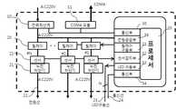
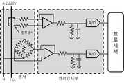
본 발명의 실시예에 따르면, A.C 전원을 공급받아 충전단자로 전류공급을 제어하고 센서를 이용 충전단자의 임피던스를 감지하여 연결상태를 인지하고 충전전류 공급을 결정하며, 충전시 흐르는 전류량을 감지하는 센서감지부; CDMA 통신을 통해 센터시스템과 연동하여 충전 시작과 과금에 대한 정보를 전달하는 통신부; 충전단자에 연결된 차량들의 충전전류 흐름과 충전 요청시간을 분석하여 피크전력이 최소가 되도록 충전전류공급을 제어하는 기능을 수행하는 충전제어기; 상기 충전제어기와 연결되어 전기자동차의 충전전원선과 연결하는 고유번호가 할당된 충전단자부; 충전단자에 연결된 차량의 충전을 핸드폰으로 요청시 센터시스템으로 연결되어 충전을 요청하는 충전단자 ID 정보를 받고 충전을 요청한 핸드폰 전화번호 정보를 이용하여 불량사용자 등을 확인하여 충전을 승인하고 충전완료 및 충전요금을 부과 통보하는 기능을 가진 센터시스템으로 핸드폰을 이용하여 전기자동차의 충전요청과 과금을 하는 기능을 제공한다.According to an embodiment of the present invention, the AC power is supplied to control the current supply to the charging terminal, by using the sensor to sense the impedance of the charging terminal to recognize the connection state, determine the charging current supply, and detect the amount of current flowing during charging Sensor detecting unit; Communication unit for transmitting the information on the charging start and charging in conjunction with the center system through the CDMA communication; A charging controller configured to control charging current supply to minimize peak power by analyzing charging current flow and charging request time of vehicles connected to the charging terminal; A charging terminal unit connected to the charging controller and assigned a unique number for connecting with a charging power line of the electric vehicle; When requesting the charging of the vehicle connected to the charging terminal through the mobile phone, it is connected to the center system to receive the charging terminal ID information requesting the charging and confirms the bad user by using the phone number information requested for the charging and approves the charging. The center system has a function of notifying charging charges and provides the function of charging and charging electric vehicles using a mobile phone.
센서 및 센서감지부는 임피던스 감지를 하여 충전단자에 전기자동차 충전선의 연결된 상태를 감지하고, 충전시 흐르는 전류량의 변화를 감지하여 충전완료 상태를 판단하여 충전전류량을 계산하고 충전을 완료시킨다. 또한 충전단자에서 제공하는 전기자동차의 통신선을 이용하여 전기자동차가 제공하는 차량의 배터리, 충전상태 및 다양한 정보를 받을 수 있어 에너지 절감을 위한 피크전력 제어와 심야전력 사용등 다양한 충전전류 제어 기능을 제공한다.Sensor and sensor detection unit detects the impedance of the electric vehicle charging line to the charging terminal by sensing the impedance, detects the change in the amount of current flowing during charging to determine the state of completion of charging to calculate the charging current amount and complete the charging. In addition, by using the communication line of the electric vehicle provided by the charging terminal, it is possible to receive the battery, state of charge and various information of the vehicle provided by the electric vehicle, thereby providing various charging current control functions such as peak power control for energy saving and midnight power use. do.
본 발명에 따르면, 기존의 공공 주차장과 같은 장기 주차장 시설에 소규모의 무인 충전시스템을 손쉽게 설치, 운영할 수 있어 전기자동차의 충전소 문제를 해결할 수 있으며, 야간 주차시 저속충전을 하여 고가의 배터리 수명을 연장할 수 있고 심야전력을 사용하여 저렴하게 충전을 할 수 있어 에너지 절감 효과와 핸드폰을 이용한 충전요청과 과금을 통보할 수 있기 때문에 손쉽게 충전을 할 수 있어 전기자동차의 활성화에 많은 기여를 할 수 있다.According to the present invention, a small unmanned charging system can be easily installed and operated in a long-term parking lot facility such as an existing public parking lot, thereby solving the problem of a charging station of an electric vehicle, and providing a low-cost charging at night parking to increase expensive battery life. It can be extended and can be charged at low cost by using midnight power, and it can be easily charged because it can be notified of energy saving effect and charge request and charge using a mobile phone, which can contribute a lot to the activation of electric vehicles. .
도 1는 본 발명에 따른 전기자동차의 충전 및 과금 시스템의 전체적인 불록구성도이다.
도 2는 본 발명에 따른 충전제어기 불록구성도이다.
도 3는 본 발명에 따른 충전단자 불록구성도이다.
도 4는 본 발명에 따른 핸드폰을 이용한 충전시스템의 서비스 방법을 순차적으로 나타내 보인 개략적인 순서도이다.
도 5는 본 발명에 따른 충전요청에 따른 충전전류 제어에 관한 도표이다.
도 6은 본 발명에 따른 센서 및 센서감지부의 개략적인 구성도이다.
1 is an overall block diagram of a charging and charging system for an electric vehicle according to the present invention.
2 is a block diagram of a charge controller according to the present invention.
3 is a block diagram of the charging terminal according to the present invention.
4 is a schematic flowchart showing sequentially a service method of a charging system using a mobile phone according to the present invention.
5 is a diagram illustrating a charging current control according to a charging request according to the present invention.
6 is a schematic configuration diagram of a sensor and a sensor detecting unit according to the present invention.
첨부된 도면을 참조하여 본 발명의 바람직한 실시 예에 대해 상세히 설명한다.With reference to the accompanying drawings will be described in detail a preferred embodiment of the present invention.
[도 1]은 본 발명의 실시 예에 따른 전기자동차의 전체 시스템에 대한 불록구성도이며, [도 2]와 [도 3]은 [도 1]에 따른 충전제어기와 충전단자의 개략적인 구성도이다. [도 4]는 핸드폰으로 충전요청과 충전방식 선택 및 충전완료 및 과금 통보를 받는 서비스 방법에 대한 개략적인 순서도 이다. [도 5]는 충전시 에너지 절감을 위해 피크전력과 심야전력을 활용한 충전전류제어 효과를 표시한 제어도표이다. [도 6]은 센서 및 센서감지부로 충전단자에 연결된 전기자동차의 충전선의 연결상태를 감지하고 충전 전류량을 감시하는 센서감지부의 개략적인 구성동이다.1 is a block diagram of the entire system of an electric vehicle according to an exemplary embodiment of the present invention, and FIGS. 2 and 3 are schematic configuration diagrams of a charging controller and a charging terminal according to FIG. 1. to be. 4 is a schematic flowchart of a service method for receiving a charging request and a charging method selection and charging completion and charging notification by a mobile phone. FIG. 5 is a control diagram showing a charging current control effect using peak power and midnight power for energy saving during charging. 6 is a schematic configuration diagram of a sensor detecting unit for detecting a connection state of a charging line of an electric vehicle connected to a charging terminal with a sensor and a sensor detecting unit and monitoring a charging current amount.
[도 1] 및 [도 2]를 참조하면, 본 실시 예에 따른 전기자동차의 배터리 충전을 위한 전력은 상용 전원인 A.C 220V를 공급받아 디지털 전력적산계(10)에 연결하여 충전제어기에 소요된 전체 전력을 측정하고 프로세서(35)는 릴레이 구동부(31)를 통해 릴레이(20)를 구동하여 충전단자로 전류를 흐르게 한다. 누전차단기(21)는 충전단자에 전기자동차의 충전선을 연결 사용시 누전이 발생하거나 문제가 발생시 전원을 차단시키는 기능을 한다. 센서(22)부는 충전단자와 연결된 전원선(53)의 전류 흐름과 임피던스 변화를 센서감지부(32)에서 감지하도록 하여 충전 케이블이 연결, 분리된 것을 감지 하고 충전전류의 양을 감지하여 충전 요금을 계산하는데 활용된다.1 and 2, the electric power for charging the battery of the electric vehicle according to the present embodiment is supplied with
통신부(30)는 디지털전력적산계(10)의 출력단자에 연결되어 디지털전산적력계(10)의 전력량을 프로세서(35)에서 받아 수시로 CDMA 모듈(11)을 통해 센터시스템의 CDMA 모듈(60)과 통신을 하여 센터시스템의 컴퓨터(61)와 연결하여 사용 전력량에 대한 정보와 다양한 정보를 상호 교환한다. LED구동부(33)는 충전단자의 콘센트(43)에 설치된 LED(42)를 구동하여 충전동작 및 정지임을 표시한다. 전원공급부(36)는 충전제어기의 동작전원을 공급한다.The
충전단자의 ID 번호(40)는 고유번호로 핸드폰으로 전화를 걸어 충전을 요청시에는 충전요청통화번호(54)로 센터시스템에 전화를 걸어(S100) 연결된 센터시스템에서는 전화번호를 인식하고 불량사용자 식별(S200)을 한 후, 충전단자 ID를 요청(S201)하며, 핸드폰에서는 충전단자의 ID번호(40)를 전송(S101)하고 센터시스템에서는 문자 또는 음성으로 충전 사양(충전시작 시간, 충전완료시간, 급속충전, 완속충전 등)을 전달(S202)하고 핸드폰에서는 선택사항을 전달(S102)한다. 센터시스템의 컴퓨터(61)는, 충전단자 상태 정보 요청(S203)을 충전제어기에 하여 충전가능 상태를 확인(S301) 한 후 충전가능 상태일 때 이러한 정보를 DB(62)에 저장하고 충전 가능 상태를 휴대폰에 전달(S205) 하고 휴대폰은 충전승인(S103)을 한 후 통화를 완료(S104) 한다. 센터시스템은 충전정보를 충전제어기에 전달(S206)한다. 충전제어부(35)는 이러한 정보를 받아 센서감지부(32)를 통해 충전케이블이 연결된것을 감지하고 충전이 가능한 상태인지를 판단하여 LED(42)를 구동하고 릴레이구동부(31)를 통해 릴레이(20)를 구동하여 충전전류를 흐르게 한다. 또한 프로세서(35)에서는 센서를 통해 충전중에 흐르는 전류를 감지하여 누적한다. 충전전류가 미세하게 흐를 때는 충전이 완료된 것으로 인식하여 충전전류를 차단하고 LED 구동을(42)을 차단하여 충전완료를 표시 하고 충전된 전류량과 충전시간을 센터시스템의 컴퓨터(61)에 전달(S304)하여 충전요금을 계산하도록 하고 센터시스템의 컴퓨터(60)는 심야전력등을 고려하여 충전요금을 계산하여 충전을 요청한 핸드폰으로 충전완료와 충전요금을 문자로 통보(S208) 해준다. 연결된 충전기에는 수시로 제어기상태 정보들을 센터시스템으로 통보(S305)하여 센터시스템에서 제어기의 동작이상 여부를 사전에 감지하여 고장수리를 신속히 할 수 있다.ID number (40) of the charging terminal to call the mobile phone to the unique number when the charge request to call the center system with the charge request call number (54) (S100) connected center system recognizes the phone number and bad user After identification (S200), request the charging terminal ID (S201), the mobile phone transmits the
특히 전력 절감을 위해 [도 5]와 같이 프로세서(35)에서는 충전단자에 연결된 모든 전기자동차에 충전전류를 공급시 전기차량의 충전배터리 특성과 충전시간을 고려 하여 일시에 많은 전류가 흐르지 않도록 충전시간을 배분하여 일정시간에 집중적으로 전류가 많이 흐르지 않도록 하여 피크전력 제어와 심야 전력 사용에 대한 제어를 하여 에너지절감을 최대한 고려하여 충전제어기가 동작 하도록 한다.In particular, in order to reduce power, as shown in FIG. 5, the
[도 3]의 충전단자 불럭도와 같이 충전을 위한 전기자동차의 충전케이블을 연결하는 콘센트(43)에는 각각 고유한 ID 번호(40)가 있어 구별이 되며 동작표시 LED(42)는 충전동작 중 켜지며, 충전이 완료 되면 꺼져서 충전상태를 표시해준다. 콘센트(43)에는 통신단자(41)가 있어 전기자동차 케이블을 연결시 전기자동차와 통신기능을 제공한다. 프로세서(35)는 통신기능을 제공하는 전기자동차와는 통신을 통해 전기자동차가 제공하는 정보(차종, 충전방식, 충전지 사양…)를 받아 충전제어에 활용한다.The
[도 5]는 충전단자에 연결된 전기자동차를 충전시 충전 선택정보와 충전시 흐르는 전류량을 감지하여 피크전력이 최소한으로 발생하고 심야전력을 최대한 사용할 수 있도록 충전제어기에서 충전전력을 제어 한 예를 보여 준다.[Figure 5] shows an example of controlling the charging power in the charging controller to detect the charging selection information and the amount of current flowing when charging the electric vehicle connected to the charging terminal to minimize the peak power and use the midnight power to the maximum give.
본 발명 시스템은 전기자동차를 충전하기 위한 시스템으로 아파트 및 다세대 주차장이나 고속도로 주차장 및 공공주차장에 소규모 단위로 설치하여 운영이 가능하며, 핸드폰으로 충전선택과 요금을 지불할 수 있어 무인으로 운영이 가능하여 전기자동차의 확대에 따른 충전소 보급 문제를 쉽게 해결할 수 있고 피크전력 제어와 심야 전력을 적극 활용 할 수 있는 장점이 있다.The present invention is a system for charging an electric vehicle can be installed and operated in small units in apartments and multi-generational parking lot or highway parking lot and public parking lot, and can be operated unattended because it can be charged and selected by a mobile phone. It can easily solve the problem of spreading charging stations due to the expansion of electric vehicles, and has the advantage of actively utilizing peak power control and midnight power.
Claims (4)
Translated fromKorean전기자동차의 전원선과 연결할 수 있는 고유 ID 번호를 갖는 콘센트와 충전중임을 표시하는 LED 표시부를 갖는 충전단자부와;
핸드폰과 CDMA 통신망으로 연결할 수 있는 센터시스템으로 휴대폰으로부터 충전요청과 승인 및 충전선택 정보를 받아 DB에 저장하고 충전제어기와 연동하여 충전승인과 충전요금을 계산하여 휴대폰에 통보하는 기능을 갖는 센터시스템과;
상기 충전제어부, 충전단자부, 센터시스템으로 구성되어 핸드폰을 이용한 전기차량의 충전요청 및 충전방식을 선택하고 충전요금을 과금 처리하는 센터시스템; 을 포함하는 것을 특징으로 하는 핸드폰을 이용한 전기자동차 충전소 시스템.Charging flows through the charging terminal through the sensor detector connected by the processor, which is composed of AC power supply, computer power meter, relay, sensor, earth leakage breaker, CDMA communication module and interworking communication unit, relay driver, sensor detector, LED driver, etc. A charge control unit for sensing an amount of current and controlling a current and interworking with a center system through CDMA communication;
A charging terminal unit having an outlet having a unique ID number that can be connected to a power line of an electric vehicle, and an LED display unit indicating charging;
It is a center system that can be connected to a mobile phone and a CDMA network. The center system has a function of receiving charge request, approval and charge selection information from a mobile phone and storing it in a DB and calculating the charge approval and charge rate in conjunction with a charge controller. ;
A center system composed of the charging control unit, a charging terminal unit, and a center system to select a charging request and a charging method of an electric vehicle using a mobile phone and charge the charging fee; Electric vehicle charging station system using a mobile phone comprising a.
The method of claim 1, wherein the impedance of the charging terminal is measured using a sensor detecting unit of the charging controller to detect the connection and abnormality of the charging line, detect the charging current amount, and analyze the charging request time to analyze the peak current and the late night power of the charging current. Charge controller to control charging current in consideration of use
The charging terminal according to claim 1, wherein the terminal connected to the charging cable of the electric vehicle has a unique ID set on the terminal, and an LED display unit indicating a charging operation state and an outlet having a built-in communication terminal for communicating with the electric vehicle.
Connected with the CDMA communication module, connected to the mobile phone requesting the charging, it receives the charging request, determines the bad user, passes the charging selection information, approves the charging, and interlocks with the charging controller to receive the charging start, completion, and charging power information. Center system that calculates the charge rate and notifies you of charge completion and charge on your mobile phone.
Priority Applications (1)
| Application Number | Priority Date | Filing Date | Title |
|---|---|---|---|
| KR1020100032884AKR20100044154A (en) | 2010-04-09 | 2010-04-09 | Electric vehicle charging station and payment system |
Applications Claiming Priority (1)
| Application Number | Priority Date | Filing Date | Title |
|---|---|---|---|
| KR1020100032884AKR20100044154A (en) | 2010-04-09 | 2010-04-09 | Electric vehicle charging station and payment system |
Publications (1)
| Publication Number | Publication Date |
|---|---|
| KR20100044154Atrue KR20100044154A (en) | 2010-04-29 |
Family
ID=42218995
Family Applications (1)
| Application Number | Title | Priority Date | Filing Date |
|---|---|---|---|
| KR1020100032884ACeasedKR20100044154A (en) | 2010-04-09 | 2010-04-09 | Electric vehicle charging station and payment system |
Country Status (1)
| Country | Link |
|---|---|
| KR (1) | KR20100044154A (en) |
Cited By (14)
| Publication number | Priority date | Publication date | Assignee | Title |
|---|---|---|---|---|
| KR101132948B1 (en)* | 2010-05-13 | 2012-04-05 | 엘에스산전 주식회사 | System, Apparatus and Method for Charge and Discharge Control of Electric Vehicle |
| WO2012045524A3 (en)* | 2010-10-08 | 2012-07-05 | Robert Bosch Gmbh | Method and charging station for electrically charging an electrical energy store |
| KR101229941B1 (en)* | 2010-12-22 | 2013-02-06 | 한국과학기술원 | Unmanned charging power control system and method for electric vehicle |
| WO2013057587A3 (en)* | 2011-10-19 | 2013-07-18 | Zeco Systems Pte Ltd | Methods and apparatuses for charging of electric vehicles |
| KR101303318B1 (en)* | 2011-11-14 | 2013-09-03 | 한전케이디엔주식회사 | System and Method for Charging the Battery of Electric Vehicle |
| US8610401B2 (en) | 2010-10-12 | 2013-12-17 | Hyundai Motor Company | Telematics device for remote charging control and method of providing service thereof |
| KR101385615B1 (en)* | 2011-07-29 | 2014-04-15 | 주식회사 유라코퍼레이션 | An electric/hybrid car, system for charge an electric/hybrid car and thereby method |
| CN106274536A (en)* | 2016-08-31 | 2017-01-04 | 河南浩越新能源科技开发有限公司 | A kind of Intelligent charging system of electric automobile |
| CN106410900A (en)* | 2016-10-18 | 2017-02-15 | 浙江绿源电动车有限公司 | Charging pile control method, charging pile control system and direct current charging pile |
| CN106410899A (en)* | 2016-10-18 | 2017-02-15 | 浙江绿源电动车有限公司 | Charging pile control method, charging pile control system and AC charging pile |
| WO2017146295A1 (en)* | 2016-02-22 | 2017-08-31 | 한찬희 | System for calculating and imposing fees on basis of parking and charging information of vehicle |
| CN107554333A (en)* | 2017-08-30 | 2018-01-09 | 享奕自动化科技(上海)有限公司 | A kind of charging device of electric automobile and charging method |
| KR20180003221A (en)* | 2016-06-30 | 2018-01-09 | 한국과학기술원 | Controlling apparatus and method for charging electric vehicles |
| KR20200058034A (en) | 2018-11-19 | 2020-05-27 | 한국전력공사 | System for managing an electric vehicle charging station and operating method thereof |
- 2010
- 2010-04-09KRKR1020100032884Apatent/KR20100044154A/ennot_activeCeased
Cited By (33)
| Publication number | Priority date | Publication date | Assignee | Title |
|---|---|---|---|---|
| KR101132948B1 (en)* | 2010-05-13 | 2012-04-05 | 엘에스산전 주식회사 | System, Apparatus and Method for Charge and Discharge Control of Electric Vehicle |
| WO2012045524A3 (en)* | 2010-10-08 | 2012-07-05 | Robert Bosch Gmbh | Method and charging station for electrically charging an electrical energy store |
| US8610401B2 (en) | 2010-10-12 | 2013-12-17 | Hyundai Motor Company | Telematics device for remote charging control and method of providing service thereof |
| KR101229941B1 (en)* | 2010-12-22 | 2013-02-06 | 한국과학기술원 | Unmanned charging power control system and method for electric vehicle |
| KR101385615B1 (en)* | 2011-07-29 | 2014-04-15 | 주식회사 유라코퍼레이션 | An electric/hybrid car, system for charge an electric/hybrid car and thereby method |
| US10861066B2 (en) | 2011-10-19 | 2020-12-08 | Zeco Systems Pte Ltd. | Methods and apparatuses for charging of electric vehicles |
| WO2013057587A3 (en)* | 2011-10-19 | 2013-07-18 | Zeco Systems Pte Ltd | Methods and apparatuses for charging of electric vehicles |
| US9348381B2 (en) | 2011-10-19 | 2016-05-24 | Zeco Systems Pte Ltd | Methods and apparatuses for charging of electric vehicles |
| US12190360B2 (en) | 2011-10-19 | 2025-01-07 | Zeco Systems Pte Ltd. | Systems and methods for charging of electric vehicles with charge balancing between multiple electric vehicle charging stations in a microgrid |
| US12175506B2 (en) | 2011-10-19 | 2024-12-24 | Zeco Systems Pte Ltd. | Systems and methods for charging of electric vehicles with charge balancing between multiple electric vehicle charging stations in a local area network |
| US11756086B2 (en) | 2011-10-19 | 2023-09-12 | Zeco Systems Pte Ltd. | Methods and systems for charging of electric vehicles |
| US11756087B2 (en) | 2011-10-19 | 2023-09-12 | Zeco Systems Pte Ltd. | Systems and methods for charging of electric vehicles with charge balancing between multiple electric vehicle charging stations |
| US11748788B2 (en) | 2011-10-19 | 2023-09-05 | Zeco Systems Pte Ltd. | Methods and systems for determining the availability of an electric vehicle charging station |
| US11715138B2 (en) | 2011-10-19 | 2023-08-01 | Zeco Systems Pte Ltd. | Methods and systems for charging of electric vehicles |
| US11715136B2 (en) | 2011-10-19 | 2023-08-01 | Zeco Systems Pte Ltd. | Methods and apparatuses for charging of electric vehicles |
| US10169783B2 (en) | 2011-10-19 | 2019-01-01 | Zeco Systems Pte Ltd. | Methods and apparatuses for charging of electric vehicles |
| US10185978B2 (en) | 2011-10-19 | 2019-01-22 | Zeco Systems Pte Ltd. | Methods and apparatuses for charging of electric vehicles |
| US10185977B2 (en) | 2011-10-19 | 2019-01-22 | Zeco Systems Pte Ltd. | Methods and apparatuses for charging of electric vehicles |
| US10192245B2 (en) | 2011-10-19 | 2019-01-29 | Zeco Systems Pte Ltd. | Methods and apparatuses for charging of electric vehicles |
| US10210552B2 (en) | 2011-10-19 | 2019-02-19 | Zeco Systems Pte Ltd. | Methods and apparatuses for charging of electric vehicles |
| US10586258B2 (en) | 2011-10-19 | 2020-03-10 | Zeco Systems Pte Ltd. | Methods and apparatuses for charging of electric vehicles |
| US10872361B2 (en) | 2011-10-19 | 2020-12-22 | Zeco Systems Pte Ltd. | Methods and apparatuses for charging of electric vehicles |
| US10839433B2 (en) | 2011-10-19 | 2020-11-17 | Zeco Systems Pte Ltd. | Methods and apparatuses for charging of electric vehicles |
| US10846763B2 (en) | 2011-10-19 | 2020-11-24 | Zeco Systems Ptd Ltd. | Methods and apparatuses for charging of electric vehicles |
| KR101303318B1 (en)* | 2011-11-14 | 2013-09-03 | 한전케이디엔주식회사 | System and Method for Charging the Battery of Electric Vehicle |
| WO2017146295A1 (en)* | 2016-02-22 | 2017-08-31 | 한찬희 | System for calculating and imposing fees on basis of parking and charging information of vehicle |
| KR101866645B1 (en)* | 2016-06-30 | 2018-06-12 | 한국과학기술원 | Controlling apparatus and method for charging electric vehicles |
| KR20180003221A (en)* | 2016-06-30 | 2018-01-09 | 한국과학기술원 | Controlling apparatus and method for charging electric vehicles |
| CN106274536A (en)* | 2016-08-31 | 2017-01-04 | 河南浩越新能源科技开发有限公司 | A kind of Intelligent charging system of electric automobile |
| CN106410899A (en)* | 2016-10-18 | 2017-02-15 | 浙江绿源电动车有限公司 | Charging pile control method, charging pile control system and AC charging pile |
| CN106410900A (en)* | 2016-10-18 | 2017-02-15 | 浙江绿源电动车有限公司 | Charging pile control method, charging pile control system and direct current charging pile |
| CN107554333A (en)* | 2017-08-30 | 2018-01-09 | 享奕自动化科技(上海)有限公司 | A kind of charging device of electric automobile and charging method |
| KR20200058034A (en) | 2018-11-19 | 2020-05-27 | 한국전력공사 | System for managing an electric vehicle charging station and operating method thereof |
Similar Documents
| Publication | Publication Date | Title |
|---|---|---|
| KR20100044154A (en) | Electric vehicle charging station and payment system | |
| CN105142964B (en) | Location-based electric power intermediary module, electric car and intermediary server and user authentication socket or connector for location-based electric power intermediary module, electric car and intermediary server | |
| KR101973502B1 (en) | Apparatus and Management Server for Charging Electric Vehicle | |
| JP6034198B2 (en) | Electric vehicle equipment for grid integrated car | |
| JP5432233B2 (en) | Electric vehicle charging control method, electric vehicle charging control system, and electric vehicle charging system | |
| CN102244401B (en) | System, apparatus and method for controlling charge and discharge of electric vehicle | |
| KR101904831B1 (en) | Intellgent building management system and method for controlling thereof | |
| JP6432816B2 (en) | Power management system, control device | |
| KR20100128349A (en) | Mobile intelligent metering and charging system for charging uniquely identifiable rechargeable vehicle destinations | |
| JP7142291B2 (en) | Charging method and charging system | |
| CN104637171B (en) | Electric vehicle charging toll collection system | |
| KR20110076859A (en) | Remote Metering System for Electric Vehicle Charging | |
| KR102361409B1 (en) | Electric vehicle sharing charging device and method using Home Energy Management System | |
| KR20190045126A (en) | Apparatus and Management Server for Charging Electric Vehicle | |
| JP2010284039A (en) | Power supply system | |
| KR101142728B1 (en) | Remote Metering System for Electric Vehicle Charging | |
| WO2013123988A2 (en) | System and method for consumption metering and transfer control | |
| JP7415406B2 (en) | Charging device, operating method, charging system, and charge/discharge control method | |
| KR20110052773A (en) | Remote Metering System for Electric Vehicle Charging | |
| CN105431986A (en) | Electric socket and method for supplying power through electric socket | |
| CN108923510B (en) | Charging circuit, system and method | |
| KR20110138564A (en) | Charging charge settlement system of electric vehicles | |
| KR100725178B1 (en) | System and method of power supplementary service using power line communication | |
| KR20110076858A (en) | Remote Metering System for Electric Vehicle Charging | |
| KR20110044006A (en) | Electric vehicle charging management system and charging management method |
Legal Events
| Date | Code | Title | Description |
|---|---|---|---|
| A201 | Request for examination | ||
| PA0109 | Patent application | Patent event code:PA01091R01D Comment text:Patent Application Patent event date:20100409 | |
| PA0201 | Request for examination | ||
| PG1501 | Laying open of application | ||
| E902 | Notification of reason for refusal | ||
| PE0902 | Notice of grounds for rejection | Comment text:Notification of reason for refusal Patent event date:20110719 Patent event code:PE09021S01D | |
| E90F | Notification of reason for final refusal | ||
| PE0902 | Notice of grounds for rejection | Comment text:Final Notice of Reason for Refusal Patent event date:20120424 Patent event code:PE09021S02D | |
| E601 | Decision to refuse application | ||
| PE0601 | Decision on rejection of patent | Patent event date:20120720 Comment text:Decision to Refuse Application Patent event code:PE06012S01D Patent event date:20120516 Comment text:Final Notice of Reason for Refusal Patent event code:PE06011S02I Patent event date:20120424 Comment text:Final Notice of Reason for Refusal Patent event code:PE06011S02I Patent event date:20110825 Comment text:Notification of reason for refusal Patent event code:PE06011S01I Patent event date:20110719 Comment text:Notification of reason for refusal Patent event code:PE06011S01I | |
| E601 | Decision to refuse application | ||
| PE0601 | Decision on rejection of patent | Patent event date:20120827 Comment text:Decision to Refuse Application Patent event code:PE06012S01D Patent event date:20120516 Comment text:Final Notice of Reason for Refusal Patent event code:PE06011S02I Patent event date:20120424 Comment text:Final Notice of Reason for Refusal Patent event code:PE06011S02I Patent event date:20110825 Comment text:Notification of reason for refusal Patent event code:PE06011S01I Patent event date:20110719 Comment text:Notification of reason for refusal Patent event code:PE06011S01I |