KR20100039332A - Thermal surgery safety suite - Google Patents
Thermal surgery safety suiteDownload PDFInfo
- Publication number
- KR20100039332A KR20100039332AKR1020107000350AKR20107000350AKR20100039332AKR 20100039332 AKR20100039332 AKR 20100039332AKR 1020107000350 AKR1020107000350 AKR 1020107000350AKR 20107000350 AKR20107000350 AKR 20107000350AKR 20100039332 AKR20100039332 AKR 20100039332A
- Authority
- KR
- South Korea
- Prior art keywords
- tissue
- temperature
- laser
- light
- treatment volume
- Prior art date
- Legal status (The legal status is an assumption and is not a legal conclusion. Google has not performed a legal analysis and makes no representation as to the accuracy of the status listed.)
- Ceased
Links
- 238000001356surgical procedureMethods0.000titledescription9
- 238000011282treatmentMethods0.000claimsabstractdescription199
- 238000000034methodMethods0.000claimsabstractdescription80
- 230000001225therapeutic effectEffects0.000claimsabstractdescription31
- 238000012546transferMethods0.000claimsabstractdescription19
- 210000001519tissueAnatomy0.000claimsdescription218
- 239000000523sampleSubstances0.000claimsdescription78
- 230000003287optical effectEffects0.000claimsdescription45
- 230000001133accelerationEffects0.000claimsdescription37
- 238000005259measurementMethods0.000claimsdescription20
- 230000003595spectral effectEffects0.000claimsdescription15
- 210000000577adipose tissueAnatomy0.000claimsdescription8
- 230000005540biological transmissionEffects0.000claimsdescription6
- 230000002500effect on skinEffects0.000claimsdescription5
- 230000002792vascularEffects0.000claimsdescription4
- 238000002430laser surgeryMethods0.000claimsdescription2
- 239000000835fiberSubstances0.000description33
- 239000003925fatSubstances0.000description26
- 238000010521absorption reactionMethods0.000description18
- 210000003491skinAnatomy0.000description17
- 238000004422calculation algorithmMethods0.000description16
- 238000012545processingMethods0.000description13
- 230000004044responseEffects0.000description12
- 230000008859changeEffects0.000description10
- 230000004130lipolysisEffects0.000description9
- 238000010438heat treatmentMethods0.000description8
- 230000005855radiationEffects0.000description8
- 239000013598vectorSubstances0.000description8
- 230000006870functionEffects0.000description7
- 230000033001locomotionEffects0.000description7
- 230000015572biosynthetic processEffects0.000description6
- 238000001816coolingMethods0.000description6
- 230000000694effectsEffects0.000description6
- 206010015037epilepsyDiseases0.000description6
- 239000013307optical fiberSubstances0.000description6
- 230000008569processEffects0.000description6
- 238000003786synthesis reactionMethods0.000description6
- 238000004364calculation methodMethods0.000description5
- 230000005484gravityEffects0.000description5
- SBIBMFFZSBJNJF-UHFFFAOYSA-Nselenium;zincChemical compound[Se]=[Zn]SBIBMFFZSBJNJF-UHFFFAOYSA-N0.000description5
- XLYOFNOQVPJJNP-UHFFFAOYSA-NwaterSubstancesOXLYOFNOQVPJJNP-UHFFFAOYSA-N0.000description5
- 230000002411adverseEffects0.000description4
- 230000008901benefitEffects0.000description4
- 238000004590computer programMethods0.000description4
- 238000001514detection methodMethods0.000description4
- 238000010586diagramMethods0.000description4
- 238000001727in vivoMethods0.000description4
- 230000000670limiting effectEffects0.000description4
- 239000011159matrix materialSubstances0.000description4
- 230000000644propagated effectEffects0.000description4
- 238000009825accumulationMethods0.000description3
- 238000009529body temperature measurementMethods0.000description3
- 238000006243chemical reactionMethods0.000description3
- 238000004891communicationMethods0.000description3
- 230000008878couplingEffects0.000description3
- 238000010168coupling processMethods0.000description3
- 238000005859coupling reactionMethods0.000description3
- 230000006378damageEffects0.000description3
- 230000007423decreaseEffects0.000description3
- 210000004207dermisAnatomy0.000description3
- 230000009977dual effectEffects0.000description3
- 238000007726management methodMethods0.000description3
- 239000000463materialSubstances0.000description3
- 230000007246mechanismEffects0.000description3
- 230000002829reductive effectEffects0.000description3
- 230000003068static effectEffects0.000description3
- 238000002835absorbanceMethods0.000description2
- 230000003321amplificationEffects0.000description2
- 238000004458analytical methodMethods0.000description2
- 238000013459approachMethods0.000description2
- 210000004027cellAnatomy0.000description2
- 239000000470constituentSubstances0.000description2
- 238000012937correctionMethods0.000description2
- 239000006185dispersionSubstances0.000description2
- 230000005670electromagnetic radiationEffects0.000description2
- 210000003195fasciaAnatomy0.000description2
- 230000004992fissionEffects0.000description2
- 238000013532laser treatmentMethods0.000description2
- 238000007443liposuctionMethods0.000description2
- 235000004213low-fatNutrition0.000description2
- 238000012544monitoring processMethods0.000description2
- 238000003199nucleic acid amplification methodMethods0.000description2
- 229920003023plasticPolymers0.000description2
- 230000009467reductionEffects0.000description2
- 230000035939shockEffects0.000description2
- 230000009466transformationEffects0.000description2
- OAICVXFJPJFONN-UHFFFAOYSA-NPhosphorusChemical compound[P]OAICVXFJPJFONN-UHFFFAOYSA-N0.000description1
- 210000001015abdomenAnatomy0.000description1
- 230000009471actionEffects0.000description1
- 210000001789adipocyteAnatomy0.000description1
- 210000003484anatomyAnatomy0.000description1
- 230000003667anti-reflective effectEffects0.000description1
- 230000000712assemblyEffects0.000description1
- 238000000429assemblyMethods0.000description1
- QVGXLLKOCUKJST-UHFFFAOYSA-Natomic oxygenChemical compound[O]QVGXLLKOCUKJST-UHFFFAOYSA-N0.000description1
- 230000000740bleeding effectEffects0.000description1
- 230000000903blocking effectEffects0.000description1
- 210000004204blood vesselAnatomy0.000description1
- 239000006227byproductSubstances0.000description1
- 230000037369collagen remodelingEffects0.000description1
- 239000003086colorantSubstances0.000description1
- 230000002301combined effectEffects0.000description1
- 238000002485combustion reactionMethods0.000description1
- 239000002131composite materialSubstances0.000description1
- 238000011109contaminationMethods0.000description1
- 230000001419dependent effectEffects0.000description1
- 230000008021depositionEffects0.000description1
- 238000003745diagnosisMethods0.000description1
- 230000037213dietEffects0.000description1
- 235000005911dietNutrition0.000description1
- 238000004980dosimetryMethods0.000description1
- 235000020457energy shotsNutrition0.000description1
- 238000010336energy treatmentMethods0.000description1
- 210000002615epidermisAnatomy0.000description1
- 230000008029eradicationEffects0.000description1
- 238000010304firingMethods0.000description1
- 229920002457flexible plasticPolymers0.000description1
- 229910052732germaniumInorganic materials0.000description1
- GNPVGFCGXDBREM-UHFFFAOYSA-Ngermanium atomChemical compound[Ge]GNPVGFCGXDBREM-UHFFFAOYSA-N0.000description1
- 230000036541healthEffects0.000description1
- 230000017525heat dissipationEffects0.000description1
- 230000002401inhibitory effectEffects0.000description1
- 239000012212insulatorSubstances0.000description1
- 230000002147killing effectEffects0.000description1
- 238000012886linear functionMethods0.000description1
- 150000002632lipidsChemical class0.000description1
- 239000002502liposomeSubstances0.000description1
- 238000013507mappingMethods0.000description1
- 238000012986modificationMethods0.000description1
- 230000004048modificationEffects0.000description1
- 210000003205muscleAnatomy0.000description1
- 230000017074necrotic cell deathEffects0.000description1
- 238000011369optimal treatmentMethods0.000description1
- 230000008520organizationEffects0.000description1
- 238000013021overheatingMethods0.000description1
- 229910052760oxygenInorganic materials0.000description1
- 239000001301oxygenSubstances0.000description1
- 230000035515penetrationEffects0.000description1
- 229910052698phosphorusInorganic materials0.000description1
- 239000011574phosphorusSubstances0.000description1
- 230000000649photocoagulationEffects0.000description1
- 230000035479physiological effects, processes and functionsEffects0.000description1
- 239000000049pigmentSubstances0.000description1
- 230000001902propagating effectEffects0.000description1
- 238000002310reflectometryMethods0.000description1
- 239000012783reinforcing fiberSubstances0.000description1
- 230000002441reversible effectEffects0.000description1
- 230000037390scarringEffects0.000description1
- 238000007650screen-printingMethods0.000description1
- 230000035807sensationEffects0.000description1
- 230000035945sensitivityEffects0.000description1
- 230000036555skin typeEffects0.000description1
- 239000007787solidSubstances0.000description1
- 229910001220stainless steelInorganic materials0.000description1
- 239000010935stainless steelSubstances0.000description1
- 230000004936stimulating effectEffects0.000description1
- 230000003685thermal hair damageEffects0.000description1
- 238000013334tissue modelMethods0.000description1
- 238000013519translationMethods0.000description1
- 230000000007visual effectEffects0.000description1
- 238000003079width controlMethods0.000description1
Images


Classifications
- A—HUMAN NECESSITIES
- A61—MEDICAL OR VETERINARY SCIENCE; HYGIENE
- A61B—DIAGNOSIS; SURGERY; IDENTIFICATION
- A61B18/00—Surgical instruments, devices or methods for transferring non-mechanical forms of energy to or from the body
- A61B18/18—Surgical instruments, devices or methods for transferring non-mechanical forms of energy to or from the body by applying electromagnetic radiation, e.g. microwaves
- A61B18/20—Surgical instruments, devices or methods for transferring non-mechanical forms of energy to or from the body by applying electromagnetic radiation, e.g. microwaves using laser
- A61B18/22—Surgical instruments, devices or methods for transferring non-mechanical forms of energy to or from the body by applying electromagnetic radiation, e.g. microwaves using laser the beam being directed along or through a flexible conduit, e.g. an optical fibre; Couplings or hand-pieces therefor
- A—HUMAN NECESSITIES
- A61—MEDICAL OR VETERINARY SCIENCE; HYGIENE
- A61B—DIAGNOSIS; SURGERY; IDENTIFICATION
- A61B18/00—Surgical instruments, devices or methods for transferring non-mechanical forms of energy to or from the body
- A61B18/18—Surgical instruments, devices or methods for transferring non-mechanical forms of energy to or from the body by applying electromagnetic radiation, e.g. microwaves
- A61B18/20—Surgical instruments, devices or methods for transferring non-mechanical forms of energy to or from the body by applying electromagnetic radiation, e.g. microwaves using laser
- A61B18/201—Surgical instruments, devices or methods for transferring non-mechanical forms of energy to or from the body by applying electromagnetic radiation, e.g. microwaves using laser with beam delivery through a hollow tube, e.g. forming an articulated arm ; Hand-pieces therefor
- A—HUMAN NECESSITIES
- A61—MEDICAL OR VETERINARY SCIENCE; HYGIENE
- A61B—DIAGNOSIS; SURGERY; IDENTIFICATION
- A61B90/00—Instruments, implements or accessories specially adapted for surgery or diagnosis and not covered by any of the groups A61B1/00 - A61B50/00, e.g. for luxation treatment or for protecting wound edges
- A61B90/36—Image-producing devices or illumination devices not otherwise provided for
- A61B90/361—Image-producing devices, e.g. surgical cameras
- A—HUMAN NECESSITIES
- A61—MEDICAL OR VETERINARY SCIENCE; HYGIENE
- A61B—DIAGNOSIS; SURGERY; IDENTIFICATION
- A61B90/00—Instruments, implements or accessories specially adapted for surgery or diagnosis and not covered by any of the groups A61B1/00 - A61B50/00, e.g. for luxation treatment or for protecting wound edges
- A61B90/36—Image-producing devices or illumination devices not otherwise provided for
- A61B90/37—Surgical systems with images on a monitor during operation
- A—HUMAN NECESSITIES
- A61—MEDICAL OR VETERINARY SCIENCE; HYGIENE
- A61B—DIAGNOSIS; SURGERY; IDENTIFICATION
- A61B17/00—Surgical instruments, devices or methods
- A61B2017/00017—Electrical control of surgical instruments
- A61B2017/00022—Sensing or detecting at the treatment site
- A61B2017/00084—Temperature
- A—HUMAN NECESSITIES
- A61—MEDICAL OR VETERINARY SCIENCE; HYGIENE
- A61B—DIAGNOSIS; SURGERY; IDENTIFICATION
- A61B17/00—Surgical instruments, devices or methods
- A61B2017/00017—Electrical control of surgical instruments
- A61B2017/00115—Electrical control of surgical instruments with audible or visual output
- A61B2017/00119—Electrical control of surgical instruments with audible or visual output alarm; indicating an abnormal situation
- A—HUMAN NECESSITIES
- A61—MEDICAL OR VETERINARY SCIENCE; HYGIENE
- A61B—DIAGNOSIS; SURGERY; IDENTIFICATION
- A61B18/00—Surgical instruments, devices or methods for transferring non-mechanical forms of energy to or from the body
- A61B2018/00053—Mechanical features of the instrument of device
- A61B2018/00166—Multiple lumina
- A—HUMAN NECESSITIES
- A61—MEDICAL OR VETERINARY SCIENCE; HYGIENE
- A61B—DIAGNOSIS; SURGERY; IDENTIFICATION
- A61B18/00—Surgical instruments, devices or methods for transferring non-mechanical forms of energy to or from the body
- A61B2018/00315—Surgical instruments, devices or methods for transferring non-mechanical forms of energy to or from the body for treatment of particular body parts
- A61B2018/00452—Skin
- A61B2018/00458—Deeper parts of the skin, e.g. treatment of vascular disorders or port wine stains
- A61B2018/00464—Subcutaneous fat, e.g. liposuction, lipolysis
- A—HUMAN NECESSITIES
- A61—MEDICAL OR VETERINARY SCIENCE; HYGIENE
- A61B—DIAGNOSIS; SURGERY; IDENTIFICATION
- A61B18/00—Surgical instruments, devices or methods for transferring non-mechanical forms of energy to or from the body
- A61B2018/00636—Sensing and controlling the application of energy
- A61B2018/00642—Sensing and controlling the application of energy with feedback, i.e. closed loop control
- A—HUMAN NECESSITIES
- A61—MEDICAL OR VETERINARY SCIENCE; HYGIENE
- A61B—DIAGNOSIS; SURGERY; IDENTIFICATION
- A61B18/00—Surgical instruments, devices or methods for transferring non-mechanical forms of energy to or from the body
- A61B2018/00636—Sensing and controlling the application of energy
- A61B2018/00696—Controlled or regulated parameters
- A61B2018/00702—Power or energy
- A—HUMAN NECESSITIES
- A61—MEDICAL OR VETERINARY SCIENCE; HYGIENE
- A61B—DIAGNOSIS; SURGERY; IDENTIFICATION
- A61B18/00—Surgical instruments, devices or methods for transferring non-mechanical forms of energy to or from the body
- A61B2018/00636—Sensing and controlling the application of energy
- A61B2018/00773—Sensed parameters
- A61B2018/00791—Temperature
- A61B2018/00815—Temperature measured by a thermistor
- A—HUMAN NECESSITIES
- A61—MEDICAL OR VETERINARY SCIENCE; HYGIENE
- A61B—DIAGNOSIS; SURGERY; IDENTIFICATION
- A61B18/00—Surgical instruments, devices or methods for transferring non-mechanical forms of energy to or from the body
- A61B2018/00636—Sensing and controlling the application of energy
- A61B2018/00773—Sensed parameters
- A61B2018/00791—Temperature
- A61B2018/00821—Temperature measured by a thermocouple
- A—HUMAN NECESSITIES
- A61—MEDICAL OR VETERINARY SCIENCE; HYGIENE
- A61B—DIAGNOSIS; SURGERY; IDENTIFICATION
- A61B18/00—Surgical instruments, devices or methods for transferring non-mechanical forms of energy to or from the body
- A61B2018/0091—Handpieces of the surgical instrument or device
- A61B2018/00916—Handpieces of the surgical instrument or device with means for switching or controlling the main function of the instrument or device
- A61B2018/00922—Handpieces of the surgical instrument or device with means for switching or controlling the main function of the instrument or device by switching or controlling the treatment energy directly within the hand-piece
- A—HUMAN NECESSITIES
- A61—MEDICAL OR VETERINARY SCIENCE; HYGIENE
- A61B—DIAGNOSIS; SURGERY; IDENTIFICATION
- A61B18/00—Surgical instruments, devices or methods for transferring non-mechanical forms of energy to or from the body
- A61B18/18—Surgical instruments, devices or methods for transferring non-mechanical forms of energy to or from the body by applying electromagnetic radiation, e.g. microwaves
- A61B18/20—Surgical instruments, devices or methods for transferring non-mechanical forms of energy to or from the body by applying electromagnetic radiation, e.g. microwaves using laser
- A61B18/22—Surgical instruments, devices or methods for transferring non-mechanical forms of energy to or from the body by applying electromagnetic radiation, e.g. microwaves using laser the beam being directed along or through a flexible conduit, e.g. an optical fibre; Couplings or hand-pieces therefor
- A61B2018/2205—Characteristics of fibres
- A—HUMAN NECESSITIES
- A61—MEDICAL OR VETERINARY SCIENCE; HYGIENE
- A61B—DIAGNOSIS; SURGERY; IDENTIFICATION
- A61B2218/00—Details of surgical instruments, devices or methods for transferring non-mechanical forms of energy to or from the body
- A61B2218/001—Details of surgical instruments, devices or methods for transferring non-mechanical forms of energy to or from the body having means for irrigation and/or aspiration of substances to and/or from the surgical site
- A61B2218/007—Aspiration
Landscapes
- Health & Medical Sciences (AREA)
- Surgery (AREA)
- Life Sciences & Earth Sciences (AREA)
- Physics & Mathematics (AREA)
- Nuclear Medicine, Radiotherapy & Molecular Imaging (AREA)
- Molecular Biology (AREA)
- General Health & Medical Sciences (AREA)
- Veterinary Medicine (AREA)
- Engineering & Computer Science (AREA)
- Biomedical Technology (AREA)
- Heart & Thoracic Surgery (AREA)
- Medical Informatics (AREA)
- Public Health (AREA)
- Animal Behavior & Ethology (AREA)
- Otolaryngology (AREA)
- Optics & Photonics (AREA)
- Electromagnetism (AREA)
- Oral & Maxillofacial Surgery (AREA)
- Pathology (AREA)
- Gynecology & Obstetrics (AREA)
- Radiology & Medical Imaging (AREA)
- Laser Surgery Devices (AREA)
- Measuring And Recording Apparatus For Diagnosis (AREA)
- Thermotherapy And Cooling Therapy Devices (AREA)
- Radiation-Therapy Devices (AREA)
Abstract
Translated fromKoreanDescription
Translated fromKorean환자들은 건강 및 외모를 향상하기 위해 그들의 신체 부위로부터 바람직하지 못한 조직을 제거하는 수술 방법에 의존해왔다. 예컨대, 일부 환자들은 상당한 식이 요법 및 운동에도 불구하고 특히 특정 부위의 지방이 빠지지 않기 때문에 지방 조직을 제거하기 위해 흡입 기구에 의해 지방이 제거되는 시술인 지방 흡인술을 선호해왔다. 달리, 레이저 또는 다른 광원이 조직을 가열, 제거, 파괴[예컨대, 사멸(killing)], 광응고, 박멸 또는 다른 처치(이하, 총괄하여 "처치" 또는 "치료"라 함)를 위해 적용되어 왔다.Patients have relied on surgical methods to remove undesirable tissue from their body parts to improve their health and appearance. For example, some patients have preferred liposuction, a procedure in which fat is removed by an inhalation device to remove adipose tissue, especially because a significant portion of fat does not fall out despite significant diet and exercise. Alternatively, lasers or other light sources have been applied for heating, removing, destroying (eg killing), photocoagulation, eradication, or other treatment (hereinafter collectively referred to as "treatment" or "treatment") of tissue. .
치료 기구는 환자의 피부 아래에 이식되기 때문에, 임상의는 예컨대 어떠한 유형의 시각적 보조구에 의해서도 치료 부위의 처치된 부분의 상태 또는 치료의 정도를 평가할 수 없다. 이와 같이, 임상의는 감각에 의한 것을 제외하고는 치료 부위의 처치되지 못한 부분으로 기구를 안내하거나 또는 치료의 정도를 결정하기 위한 다른 어떠한 수단도 제공받지 못한다. 따라서, 시술 중 환자 피부에 심미적으로 아름답지 못한 자국을 남길 수도 있는 바람직하지 못한 조직의 불균일한 제거를 초래하는 것은 드문 일이 아니다.Since the treatment instrument is implanted under the skin of the patient, the clinician cannot assess the condition or extent of treatment of the treated portion of the treatment site, for example by any type of visual aid. As such, the clinician is not provided with any means for guiding the instrument to the untreated portion of the treatment site or for determining the extent of treatment except by sensation. Thus, it is not uncommon to cause uneven removal of undesirable tissue that may leave aesthetically unsatisfactory marks on the patient's skin during the procedure.
또한, 통상의 용례에서, 레이저 지방 분해와 같은 시술 도중 레이저 전달 섬유의 전방의 조직 유형을 확인할 수 있는 직접적인 방법이 없다. 의사는 쓸모없는 지방층에 섬유 팁을 위치시키기 위해서 자신의 해부학 및 인체 생리학 지식에 의존한다. 의사는 전달 섬유를 통해 단일 또는 다중 파장을 운반하는 가시적 조준 비임에 의해 도움을 받는다. 숙련된 의사는 피부 아래의 섬유 팁 위치와 깊이를 원조 비임 가시도와 관련시킬 수 있다. 그러나, 숙련된 의사라 할지라도 섬유 팁 전방의 조직 유형을 결정하는 것은 매우 어렵다(거의 불가능하다).In addition, in conventional applications, there is no direct way to identify the anterior tissue type of the laser delivery fiber during a procedure such as laser lipolysis. Doctors rely on their anatomy and human physiology knowledge to locate fiber tips in useless fat layers. The physician is assisted by a visible aiming beam that carries single or multiple wavelengths through the delivery fiber. The skilled practitioner can relate the position and depth of the fiber tip under the skin to the aid beam visibility. However, even an experienced physician is very difficult (almost impossible) to determine the type of tissue in front of the fiber tip.
또한, 조직이 레이저 또는 광 에너지 공급부의 조직 내 흡수의 결과로 레이저 또는 레이저 에너지 공급부를 이용하여 처치될 수 있지만, 수술 기구는 치료 부위의 처치 부분에 의해 흡수된 파워의 양을 고려하는 기구가 결여되어 있다. 따라서, 임상의는 불충분한 처치 또는 과도한 처치를 하게 되어, 과도한 노출에 의해 조직을 태우거나 또는 조직을 불완전하게 제거하게 된다.In addition, although the tissue may be treated using a laser or laser energy supply as a result of absorption in the tissue of the laser or light energy supply, the surgical instrument lacks an instrument that takes into account the amount of power absorbed by the treatment portion of the treatment site. It is. Thus, the clinician may have insufficient or excessive treatment, resulting in burning or incomplete removal of tissue by excessive exposure.
본 발명자들은 에너지가 목표 조직으로 유도되는 의료 환경(예컨대, 레이저 수술)에서 사용하기 위한 하나 이상의 센서를 제공함으로써 안전성을 증가시키고 사용을 간편하게 하였다. 다양한 형태의 센서 입력을 조합함으로써, 진행중인 의료 시술을 특징화하는 다수의 정보가 제공될 수 있다.We have increased safety and simplified use by providing one or more sensors for use in a medical environment (eg, laser surgery) where energy is directed to target tissues. By combining the various types of sensor inputs, a number of information can be provided that characterize an ongoing medical procedure.
예컨대, 본 발명자들은 원치않는 조직 또는 신체 일부를 제거하기 위한 시술 도중 사용되는 수술 기기의 움직임을 검출하는 기구를 포함하는 방법 및 기기를 개시하였다.For example, the inventors have disclosed methods and devices that include a mechanism for detecting the movement of a surgical instrument used during a procedure to remove unwanted tissue or body parts.
조직 내에 파워를 제공하는 것은 구성 조직(constituent tissue)의 흡수율에 따라 국부적인 온도 상승을 초래한다. 전파 거리는 예컨대 파장/조직 유형에 따라 결정된다. 또한, 각각의 조직 유형은 관련 시간 상수 및 열전도성을 가진다. 따라서, 원칙적으로 생체내의 조직 온도 상승은 치료 부위에 삽입되는 기기의 에너지 전달 구성 요소의 위치를 알 수 있다면, 구성 조직, 파장 및 유도되는 파워를 인지함으로써 결정될 수 있다.Providing power in the tissue results in local temperature rise depending on the rate of absorption of the constituent tissue. The propagation distance is determined for example by the wavelength / tissue type. In addition, each tissue type has an associated time constant and thermal conductivity. Thus, in principle, tissue temperature rise in vivo can be determined by knowing the constituent tissue, wavelength, and induced power, provided that the location of the energy delivery component of the device inserted into the treatment site is known.
본 발명의 일 양태에 따르면, 에너지 전달 구성 요소의 위치는 속도 피드백을 제공하도록 적분되는 기기의 가속도 처리에 의해 결정될 수 있다. 속도 피드백을 계산함으로써, 기기는 속도 피드백의 값에 관련하여 치료 부위로 유도되는 파워의 양을 제어할 수 있다. 예컨대, 기기는 과도한 생체내 열효과(in vivo thermal effect)를 방지하기 위해 기기가 가동중이지 않거나 소정값 이하의 속도로 가동중일 때 치료 부위로 유도되는 에너지 방출을 중지시킬 수 있다. 또한, 속도 피드백은 가해지는 에너지 선량을 제어하도록, 예컨대 이동된 단위당 조직에 부과된 고정된 에너지를 유지하도록 이용될 수 있다.According to one aspect of the present invention, the position of the energy transfer component can be determined by the acceleration process of the instrument integrated to provide velocity feedback. By calculating the velocity feedback, the instrument can control the amount of power directed to the treatment site in relation to the value of the velocity feedback. For example, the device can stop the release of energy directed to the treatment site when the device is not running or at a rate below a predetermined value to prevent excessive in vivo thermal effects. In addition, velocity feedback can be used to control the energy dose applied, for example to maintain a fixed energy imposed on the tissue per moved unit.
본 발명의 다른 양태에 따르면, 에너지 전달 구성 요소의 위치는 치료 부위 내의 에너지 전달 구성 요소의 위치 피드백을 제공하도록 속도의 1차 적분(또는 가속도의 2차 적분)을 취함으로써 결정될 수 있다. 위치 피드백 적용을 위한 파워 제어는 파워 대 위치차 알고리즘(difference-in-position algorithm)으로 수행된다. 예컨대, 치료 부위의 조직 내로의 각각의 에너지 방출/샷(energy discharge/shot)은 8 사분면 상의 3-D 데카르트 지점으로 부여된다. 데카르트 기준면 상의 각각의 지점은 "가열 용기"를 나타낸다. 가열 용기의 온도 값은 가해진 에너지 또는 에너지-인(Ein, energy-in)과, 흡수율(absorbance) 대 전파 거리(propagation distance)와, 기준선 온도(baseline temperature)와, 조직 유형과 관련된 전도도 및 시간 상수에 따라 증가 및 감소한다. 조직 유형 측정 및 직접 또는 간접 온도 측정과 같은 추가적인 센서 입력은 공간 에너지 분포 정보를 증가시키거나 또는 확인하기 위해 위치 정보와 함께 사용될 수 있다.According to another aspect of the present invention, the position of the energy delivery component can be determined by taking a first integral of velocity (or a second integral of acceleration) to provide positional feedback of the energy transfer component within the treatment site. Power control for position feedback application is performed with a power-difference-in-position algorithm. For example, each energy discharge / shot into the tissue at the treatment site is given to a 3-D Cartesian point on eight quadrants. Each point on the Descartes reference plane represents a “heating vessel”. The temperature value of the heating vessel is applied to the energy or energy-in (Ein, energy-in) and the absorption (absorbance) versus propagation distance (propagation distance), a conductivity and a time related to the base line temperature (baseline temperature), and a tissue type, It increases and decreases with a constant. Additional sensor inputs, such as tissue type measurements and direct or indirect temperature measurements, can be used with the location information to increase or verify spatial energy distribution information.
본 발명의 일 양태에서, 레이저 수술 기기는 핸드피스를 포함하고, 핸드피스는, 공급부로부터 치료 용적으로 레이저 에너지를 전송하는 광 전달 구성 요소와, 핸드피스의 가속도를 나타내는 가속도 정보를 제공하도록 구성된 가속도계와, 치료 용적 내의 조직의 온도를 나타내는 온도 정보를 제공하도록 구성된 온도 센서와, 치료 용적 내의 조직의 유형을 나타내는 조직 유형 정보를 제공하도록 구성된 조직 유형 센서를 포함한다. 레이저 수술 기기는, 가속도계, 온도 센서, 조직 유형 센서 및 공급부에 커플링되고, 가속도 정보, 온도 정보 및 조직 유형 정보를 기초로 치료 용적으로 전송되는 레이저 에너지를 제어하도록 구성된 프로세서를 포함한다.In one aspect of the invention, a laser surgical instrument includes a handpiece, the handpiece comprising an optical delivery component that transmits laser energy from the supply to the therapeutic volume and an accelerometer configured to provide acceleration information indicative of the acceleration of the handpiece. And a temperature sensor configured to provide temperature information indicative of the temperature of the tissue in the treatment volume and a tissue type sensor configured to provide tissue type information indicative of the type of tissue in the treatment volume. The laser surgical instrument includes a processor coupled to the accelerometer, the temperature sensor, the tissue type sensor and the supply and configured to control the laser energy transmitted to the treatment volume based on the acceleration information, the temperature information and the tissue type information.
일부 실시예에서, 핸드피스는 환자의 절개부를 통해 치료 용적으로 삽입되도록 된 프로브 부재를 포함한다. 프로브 부재는, 프로브 부재의 팁에 인접한 부위로부터 레이저 에너지를 방사하는 광학 전달 요소의 적어도 일부분을 포함한다.In some embodiments, the handpiece includes a probe member adapted to be inserted into the therapeutic volume through the incision of the patient. The probe member includes at least a portion of an optically transmissive element that emits laser energy from a site adjacent the tip of the probe member.
일부 실시예에서, 프로세서는 가속도 정보를 기초로 핸드피스의 속도를 나타내는 속도 정보를 결정하고, 속도 정보를 기초로 치료 용적으로 전송되는 레이저 에너지를 제어하도록 구성된다.In some embodiments, the processor is configured to determine speed information indicative of the speed of the handpiece based on the acceleration information and to control the laser energy transmitted to the treatment volume based on the speed information.
일부 실시예에서, 프로세서는 가속도 정보를 기초로 핸드피스의 위치를 나타내는 위치 정보를 결정하고, 위치 정보를 기초로 치료 용적으로 전송되는 레이저 에너지를 제어하도록 구성된다.In some embodiments, the processor is configured to determine position information indicative of the position of the handpiece based on the acceleration information and to control the laser energy transmitted to the treatment volume based on the position information.
일부 실시예에서, 온도 센서는 서미스터 또는 열전대를 포함한다.In some embodiments, the temperature sensor includes a thermistor or thermocouple.
일부 실시예에서, 온도 센서는 적외선 센서를 포함한다.In some embodiments, the temperature sensor comprises an infrared sensor.
일부 실시예에서, 핸드피스는 치료 용적으로부터 적외선 센서로 적외선을 전송하도록 구성된 광학 감지 요소를 포함한다.In some embodiments, the handpiece includes an optical sensing element configured to transmit infrared light from the treatment volume to the infrared sensor.
일부 실시예에서, 프로세서는 핸드피스의 속도를 임계치와 비교하고, 속도가 임계치 아래에 있을 때 치료 용적으로의 레이저 에너지 전송을 금지하도록 구성된다.In some embodiments, the processor is configured to compare the speed of the handpiece to a threshold and prohibit laser energy transfer to the treatment volume when the speed is below the threshold.
일부 실시예에서, 프로세서는 조직의 온도를 임계치와 비교하고, 온도가 임계치 위에 있을 때 치료 용적으로의 레이저 에너지 전송을 금지하도록 구성된다. 다른 실시예에서, 프로세서는 조직 유형 정보를 기초로 프로브 부재의 팁에 인접한 조직의 유형을 결정하고, 프로브 부재의 팁에 인접한 조직이 민감한 조직 유형일 때 치료 용적으로의 레이저 에너지 전송을 금지하도록 구성된다.In some embodiments, the processor is configured to compare the temperature of the tissue to a threshold and prohibit laser energy transfer to the treatment volume when the temperature is above the threshold. In another embodiment, the processor is configured to determine the type of tissue adjacent the tip of the probe member based on tissue type information, and to prohibit laser energy transfer to the treatment volume when the tissue adjacent the tip of the probe member is a sensitive tissue type. .
일부 실시예에서, 민감한 조직 유형은 지방 조직의 부위에서 혈관성 조직을 포함한다. 다른 실시예에서, 민감한 조직 유형은 지방 조직의 부위를 덮는 진피 조직을 포함한다.In some embodiments, the sensitive tissue type comprises vascular tissue at the site of adipose tissue. In another embodiment, the sensitive tissue type comprises dermal tissue covering a site of adipose tissue.
일부 실시예에서, 조직 유형 센서는, 프로세서에 커플링된 광학 검출기와, 치료 부위로부터 측정 광을 수용하여 이 광을 광학 검출기로 유도하도록 구성되는 광학 감지 요소를 포함한다. 광학 검출기는 다양한 파장에서 복수의 측정광 성분의 강도를 검출하도록 구성된다.In some embodiments, the tissue type sensor includes an optical detector coupled to the processor and an optical sensing element configured to receive measurement light from the treatment site and direct the light to the optical detector. The optical detector is configured to detect the intensity of the plurality of measured light components at various wavelengths.
일부 실시예에서, 광학 감지 요소는 광 전달 구성 요소를 포함한다.In some embodiments, the optical sensing element comprises a light transmitting component.
일부 실시예에서, 조직 유형 센서는, 프로브 광 공급부와, 프로브 광 공급부로부터 치료 용적으로 프로브 광을 유도하도록 구성되는 광학 프로브 요소를 포함한다. 광학 감지 요소는 프로브 광의 일부를 목표 용적으로부터 광학 검출기로 향하게 한다.In some embodiments, the tissue type sensor includes a probe light supply and an optical probe element configured to direct probe light from the probe light supply to the therapeutic volume. The optical sensing element directs a portion of the probe light from the target volume to the optical detector.
일부 실시예에서, 프로브 광은 다양한 파장에서 복수의 분광 성분을 포함한다.In some embodiments, the probe light includes a plurality of spectral components at various wavelengths.
일부 실시예에서, 프로브 광은 약 532nm의 파장의 분광 성분과 약 635nm의 파장의 분광 성분을 포함한다.In some embodiments, the probe light comprises a spectral component at a wavelength of about 532 nm and a spectral component at a wavelength of about 635 nm.
일부 실시예에서, 광학 프로브 요소는 프로브 광이 치료 용적으로 전송되도록 프로브 광을 광 전달 구성 요소로 유도하는 광학 요소를 포함한다.In some embodiments, the optical probe element includes an optical element that directs the probe light to the light transmitting component such that the probe light is transmitted to the therapeutic volume.
일부 실시예에서, 측정 광은 목표 용적 내의 조직에 의해 반사되고, 산란되고, 재방사되는 프로브 광 부분을 포함한다.In some embodiments, the measurement light includes a portion of the probe light that is reflected, scattered, and re-radiated by tissue in the target volume.
일부 실시예에서, 광학 검출기는 컬러 광 검출기를 포함한다.In some embodiments, the optical detector comprises a color light detector.
본 발명의 다른 양태에서, 레이저 수술 기기는 핸드피스를 포함하고, 핸드피스는, 공급부로부터 치료 용적으로 레이저 에너지를 전송하는 광 전달 구성 요소와, 핸드피스의 위치를 나타내는 위치 정보를 제공하도록 구성된 가속도계와, 치료 용적 내의 조직의 유형을 나타내는 조직 유형 정보를 제공하도록 구성된 조직 유형 센서를 포함한다. 레이저 수술 기기는, 가속도계 및 공급부에 커플링되고, 치료 용적으로 전송되는 레이저 에너지를 제어하도록 구성된 프로세서와 디스플레이를 포함한다. 프로세서는 위치 정보와 조직 유형 정보를 기초로 치료 용적 내의 복수의 위치들 각각에 전달되는 에너지량을 표시하는 정보를 결정하도록 구성된다. 디스플레이는 치료 용적 내의 복수의 위치들 각각에 전달되는 에너지량을 나타내는 그래픽 화상을 표시하도록 구성된다.In another aspect of the invention, a laser surgical device includes a handpiece, the handpiece comprising an optical delivery component that transmits laser energy from the supply to the therapeutic volume, and an accelerometer configured to provide position information indicative of the position of the handpiece. And a tissue type sensor configured to provide tissue type information indicative of the type of tissue in the treatment volume. The laser surgical instrument includes a processor and a display coupled to the accelerometer and the supply and configured to control laser energy transmitted to the treatment volume. The processor is configured to determine information indicative of the amount of energy delivered to each of the plurality of locations in the treatment volume based on the location information and tissue type information. The display is configured to display a graphical image representing the amount of energy delivered to each of the plurality of locations in the treatment volume.
일부 실시예에서, 그래픽 화상은 치료 용적의 맵을 포함하고, 상기 맵 상의 복수의 지점들은 치료 용적 내의 복수의 위치들에 대응하고, 각각의 지점들의 그래픽 화질은 치료 용적 내의 위치로 전달되는 에너지량에 따라 결정된다.In some embodiments, the graphical image comprises a map of the treatment volume, wherein the plurality of points on the map correspond to the plurality of locations in the treatment volume, and the graphic quality of each of the points is an amount of energy delivered to a position in the treatment volume. It depends on.
일부 실시예에서, 그래픽 화상은 삼차원 화상이다.In some embodiments, the graphical image is a three-dimensional image.
일부 실시예에서, 프로세서는 위치 정보와 조직 유형 정보를 기초로 치료 용적 내의 복수의 위치 각각에서의 온도량을 나타내는 정보를 결정하도록 구성된다. 디스플레이는 치료 용적 내의 복수의 위치 각각에서의 온도량을 나타내는 그래픽 화상을 표시하도록 구성된다.In some embodiments, the processor is configured to determine information indicative of the amount of temperature at each of the plurality of locations in the treatment volume based on the location information and tissue type information. The display is configured to display a graphical image representing the amount of temperature at each of the plurality of locations in the treatment volume.
일부 실시예에서, 핸드피스는 치료 용적 내의 위치들에서 조직의 온도를 나타내는 온도 정보를 제공하도록 구성된 온도 센서를 더 포함한다. 프로세서는 온도 센서에 커플링되고, 위치 정보, 온도 정보 및 조직 유형 정보를 기초로 치료 용적 내의 복수의 위치들 중 적어도 하나의 온도를 나타내는 정보를 결정하도록 구성된다.In some embodiments, the handpiece further comprises a temperature sensor configured to provide temperature information indicative of the temperature of the tissue at locations within the treatment volume. The processor is coupled to the temperature sensor and is configured to determine information indicative of the temperature of at least one of the plurality of locations in the treatment volume based on the location information, the temperature information and the tissue type information.
다른 양태에서, 핸드피스를 포함하는 기기가 개시되고, 핸드피스는, 공급부로부터 치료 용적으로 레이저 에너지를 전송하는 광 전달 구성 요소와, 치료 용적 내의 조직의 온도를 나타내는 온도 정보를 제공하도록 구성된 온도 센서와, 치료 용적 내의 조직의 유형을 나타내는 조직 유형 정보를 제공하도록 구성된 조직 유형 센서를 포함한다. 조직 유형 센서는, 다양한 파장에서 복수의 분광 성분을 갖는 프로브 광을 발생하는 프로브 광 공급부와, 프로브 광 공급부로부터 치료 용적으로 프로브 광을 유도하도록 구성되는 광학 프로브 요소와, 광학 검출기와, 치료 부위로부터 측정 광을 수용하여 이 광을 광학 검출기로 유도하도록 구성되는 광학 감지 요소를 포함한다. 광학 검출기는 다양한 파장에서 측정 광의 복수의 분광 성분의 강도를 검출하고 비교하도록 구성된다. 본 기기는, 조직 유형 센서 및 공급부에 커플링되고, 조직 유형 정보를 기초로 치료 용적으로 전송되는 레이저 에너지를 제어하도록 구성된 프로세서를 포함한다.In another aspect, an apparatus is disclosed that includes a handpiece, the handpiece comprising a light transmitting component that transmits laser energy from a supply to a treatment volume and a temperature sensor configured to provide temperature information indicative of the temperature of tissue within the treatment volume. And a tissue type sensor configured to provide tissue type information indicative of the type of tissue in the treatment volume. The tissue type sensor includes a probe light supply for generating probe light having a plurality of spectral components at various wavelengths, an optical probe element configured to direct the probe light from the probe light supply to the therapeutic volume, an optical detector, and a treatment site from And an optical sensing element configured to receive the measurement light and direct the light to the optical detector. The optical detector is configured to detect and compare the intensities of the plurality of spectral components of the measured light at various wavelengths. The device includes a processor coupled to a tissue type sensor and a supply and configured to control laser energy transmitted to the treatment volume based on tissue type information.
일부 실시예에서, 프로브 광은 약 532nm의 파장의 분광 성분과 약 635nm의 파장의 분광 성분을 포함한다.In some embodiments, the probe light comprises a spectral component at a wavelength of about 532 nm and a spectral component at a wavelength of about 635 nm.
일부 실시예에서, 광학 프로브 요소는 프로브 광이 치료 용적으로 전송되도록 프로브 광을 광 전달 구성 요소로 유도하는 광학 요소를 포함한다.In some embodiments, the optical probe element includes an optical element that directs the probe light to the light transmitting component such that the probe light is transmitted to the therapeutic volume.
일부 실시예에서, 측정 광은 목표 용적 내의 조직에 의해 반사되고, 산란되고, 재방사되는 프로브 광 부분을 포함한다.In some embodiments, the measurement light includes a portion of the probe light that is reflected, scattered, and re-radiated by tissue in the target volume.
일부 실시예에서, 광학 검출기는 컬러 광 검출기를 포함한다.In some embodiments, the optical detector comprises a color light detector.
본 발명의 다른 양태에서, 레이저 수술 방법은, 공급부로부터 치료 용적으로 레이저 에너지를 전송하는 광 전달 구성 요소와, 핸드피스의 가속도를 나타내는 가속도 정보를 제공하도록 구성된 가속도계와, 치료 용적 내의 조직의 온도를 나타내는 온도 정보를 제공하도록 구성된 온도 센서와, 치료 용적 내의 조직의 유형을 나타내는 조직 유형 정보를 제공하도록 구성된 조직 유형 센서를 포함하는 핸드피스를 제공하는 단계를 포함한다. 본 방법은 공급부로부터 치료 용적으로 레이저 에너지를 전송하는 단계와, 가속도, 온도 및 조직 유형 정보를 결정하기 위해 가속도계, 온도 센서 및 조직 유형 센서를 이용하는 단계와, 가속도 정보, 온도 정보 및 조직 유형 정보를 기초로 치료 용적으로 전송되는 레이저 에너지를 제어하는 단계를 포함한다.In another aspect of the invention, a laser surgical method includes a light delivery component that transmits laser energy from a supply to a treatment volume, an accelerometer configured to provide acceleration information indicative of the acceleration of the handpiece, and the temperature of the tissue within the treatment volume. Providing a handpiece comprising a temperature sensor configured to provide the indicating temperature information and a tissue type sensor configured to provide tissue type information indicative of the type of tissue in the treatment volume. The method includes transmitting laser energy from a supply to a treatment volume, using an accelerometer, temperature sensor, and tissue type sensor to determine acceleration, temperature, and tissue type information, and using the acceleration information, temperature information, and tissue type information. Controlling the laser energy transmitted on the basis of the treatment volume.
다양한 실시예들은 전술한 특징을 단독 또는 조합하여 포함할 수 있다.Various embodiments may include the features described above alone or in combination.
본 발명에 따르면, 치료 부위의 처치되지 못한 부분으로 기구를 안내하거나 또는 치료의 정도를 결정하기 위한 수단이 제공되어, 시술 중 환자 피부에 심미적으로 아름답지 못한 자국을 남길 수도 있는 바람직하지 못한 조직의 불균일한 제거를 방지할 수 있다.According to the present invention, a means is provided for guiding the instrument to an untreated portion of the treatment site or for determining the extent of treatment, which may result in undesired aesthetic scarring of the patient's skin during the procedure. Uneven removal can be prevented.
전술한 설명은 다른 도면에서 유사한 참조 부호가 유사한 부분을 나타내는 첨부된 도면을 참조하여 본 발명의 다음의 상세한 설명을 통해 명백해진다. 도면은 축척으로 그려진 것은 아니며, 본 발명의 예시적인 실시예에 중점을 둔다.
도 1은 레이저 수술 시스템의 개략도이다.
도 1a는 본 발명의 장치에서의 가속도계의 일 실시예를 도시한 분해도이다.
도 2는 처치 중에 치료 부위에 적용되는 본 발명의 장치를 도시하는 도면이다.
도 3a는 1축, 2축 또는 3축으로 가속도를 변형하는 장치의 일 실시예의 특징을 도시하고, 도 3b는 본 발명의 장치에 장착된 가속도계의 일 실시예를 도시한다.
도 4는 본 발명의 변환기 처리 회로의 일 실시예에서의 필터 및 입력 증폭기를 도시하는 개략도이다.
도 5는 속도 대 파워 적용에서의 전체 속도 추정에 대한 개략적인 다이어그램이다.
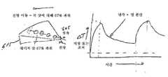
도 6a 및 도 6b는 치료 부위의 일부분에 열 쇼크를 감소시키고 치료 부위에 걸쳐 더욱 균일한 에너지 분포를 제공하는 파워 출력의 모드를 도시한다.
도 7은 최소 속도 대 파워 곡선을 도시하는 그래프이다.
도 8은 파워 출력면에서 장치의 속도와, 장치에 의한 펄스의 반복률을 도시하는 그래프이다.
도 9는 오프셋 속도 대 파워 곡선을 도시하는 그래프이다.
도 10은 파워 대 위치차 애플리케이션에서 3차원 데카르트 평면에서 3축 위치를 구성하는 모드를 도시한다.
도 11은 처치 및 비처치 부분을 나타내는 치료 부위의 2차원 맵을 도시한다.
도 12a 내지 도 12d는 중첩 펄스와, 치료 부위의 맵에 대한 그러한 중첩 펄스를 계수하는 모드를 도시한다.
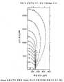
도 13a 내지 도 13c는 1064nm, 1320nm, 1400nm 공급부에 의해 각각 치료 부위에서 단열적인 온도 상승을 도시하는 그래프이다.
도 14는 Ein 대 전파 거리의 간질(interstitial) 목표 및 구성 내의 물리적 노드를 포함하는 3차원 좌표를 도시한다.
도 15는 장치 및 광학 검출기 센서 패드의 실시예를 포함하는 수술 시스템의 일 실시예를 도시한다.
도 16은 도핑 비임에 사용되는 다중 파장을 도시하는 그래프이다.
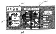
도 17은 광학 검출기 센서 패드와 통신하는 사용자 인터페이스 디스플레이의 일 실시예를 도시한다.
도 18은 열 센서를 특징으로 하는 수술 장치를 도시한다.
도 19는 열 센서를 특징으로 하는 수술 장치를 도시한다.
도 20은 열 센서를 특징으로 하는 수술 장치의 실시예를 도시한다.
도 21은 수술 장치를 제어하는 피드백 루프를 도시한다.
도 22는 수술 장치를 제어하는 피드백 루프를 도시한다.
도 23은 수술 장치를 위한 온도-위치 맵핑을 도시하는 개략도이다.
도 24는 IR 열 센서를 특징으로 하는 수술 장치를 도시한다.
도 25는 IR 열 센서를 특징으로 하는 수술 장치를 도시한다.
도 26은 반사 방지 코팅된 ZnSe의 전송 특성의 그래프를 도시한다.
도 27은 조직 유형 센서를 도시한다.
도 28은 조직 유형 센서를 도시한다.
도 29는 감지 도파관을 특징으로 하는 조직 유형 센서를 도시한다.
도 30은 이중 컬러 조직 유형 센서를 도시한다.
도 31은 조직 유형 센서에 사용되는 전자 회로를 도시한다.
도 32는 조직 유형 센서에 사용되는 전자 회로를 도시한다.
도 33은 컬러 광 검출기에 대한 응답 곡선을 도시한다.The foregoing description will become apparent from the following detailed description of the invention with reference to the accompanying drawings in which like reference numerals refer to like parts in other drawings. The drawings are not to scale, focusing on exemplary embodiments of the invention.
1 is a schematic diagram of a laser surgical system.
1A is an exploded view showing one embodiment of an accelerometer in the apparatus of the present invention.
2 shows a device of the present invention applied to a treatment site during treatment.
FIG. 3A illustrates a feature of one embodiment of an apparatus for modifying acceleration in one axis, two axes, or three axes, and FIG. 3B shows one embodiment of an accelerometer mounted in the device of the present invention.
4 is a schematic diagram illustrating a filter and an input amplifier in one embodiment of the converter processing circuit of the present invention.
5 is a schematic diagram for overall speed estimation in speed versus power application.
6A and 6B show modes of power output that reduce heat shock to a portion of the treatment site and provide a more uniform energy distribution across the treatment site.
7 is a graph showing the minimum speed versus power curve.
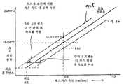
8 is a graph showing the speed of the device in terms of power output and the repetition rate of pulses by the device.
9 is a graph illustrating the offset velocity versus power curve.
FIG. 10 illustrates a mode for configuring three axis positions in a three-dimensional Cartesian plane in a power versus position difference application.
11 shows a two-dimensional map of treatment sites showing treated and untreated parts.
12A-12D show overlapping pulses and the mode of counting such overlapping pulses for a map of the treatment site.
13A-13C are graphs showing adiabatic temperature rises at treatment sites, respectively, by 1064 nm, 1320 nm, and 1400 nm supplies.
FIG. 14 shows three-dimensional coordinates including the interstitial target of Ein versus propagation distance and physical nodes in the configuration.
15 illustrates one embodiment of a surgical system including an embodiment of an apparatus and an optical detector sensor pad.
16 is a graph showing the multiple wavelengths used for the doping beams.
17 illustrates one embodiment of a user interface display in communication with an optical detector sensor pad.
18 shows a surgical device featuring a thermal sensor.
19 shows a surgical device featuring a thermal sensor.
20 illustrates an embodiment of a surgical device featuring a thermal sensor.
21 shows a feedback loop controlling the surgical device.
22 shows a feedback loop controlling the surgical device.
23 is a schematic diagram illustrating temperature-position mapping for a surgical device.
24 illustrates a surgical device featuring an IR thermal sensor.
25 illustrates a surgical device featuring an IR thermal sensor.
FIG. 26 shows a graph of the transmission properties of antireflective coated ZnSe.
27 illustrates a tissue type sensor.
28 illustrates a tissue type sensor.
29 shows a tissue type sensor characterized by a sensing waveguide.
30 shows a dual color tissue type sensor.
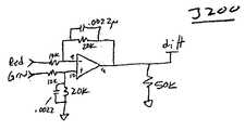
31 illustrates an electronic circuit used for a tissue type sensor.
32 illustrates electronic circuitry used for tissue type sensors.
33 shows the response curve for the color light detector.
이하에 본 발명의 실시예가 설명된다.An embodiment of the present invention is described below.
도 1은 본 명세서에 설명된 유형의 몇 가지 안전 및 제어 특징부를 나타내는 레이저 수술 시스템(10)을 도시한다. 시스템은 임상의 또는 다른 조작자에 의해 파지되고 치료 레이저 에너지를 레이저 공급부(14)로부터 치료 부위로 (예컨대, 광 섬유를 통해) 전달하도록 구성되는 핸드피스(12)를 포함한다. 제어기(15)는 예컨대 공급부(14)로부터 치료 부위로 광의 전달을 허용 또는 금지함으로써 또는 강도, 파장, 펄스 비율(pluse rate) 등과 같은 하나 이상의 레이저 파라미터를 제어함으로써, 치료 레이저 에너지의 전달을 제어하도록 작동한다. 핸드피스(12)는 다양한 유형의 다중 센서(16a, 16b, 16c)를 포함한다. 예컨대, 본 실시예에서 센서(16a)는 가속도계이고, 센서(16b)는 온도 센서이며, 센서(16c)는 조직 유형 센서(tissue type sensor)이다.1 illustrates a laser
센서(16a 내지 16c)는 제어기(15)에 연결되고, 제어기는 진행중인 치료에 관한 정보를 결정하도록 신호의 출력을 처리할 수 있다. 제어기(15)는 처리된 정보를 기초로 센서(16a 내지 16c) 및 제어 레이저(15)에 의해 측정된 정보를 처리할 수 있다. 센서(16a 내지 16c)의 각각으로부터의 정보는 치료 중인 부위에 관한 다양한 실시간 정보를 제공하도록 별개로 또는 조합하여 이용될 수 있다. 이러한 정보는 임상의에게 표시될 수 있거나, 또는 예컨대 위험한 상태(예컨대, 치료 부위 일부의 과열)가 검출된 경우에, 레이저(15)를 중지하거나 또는 치료 부위에 걸쳐 바람직한 선량 프로파일(dose profile)을 제공하기 위해 레이저(15)를 자동 제어하는데 사용될 수 있다. 일부 실시예에서, 센서(16a 내지 16c)로부터의 정보는 상호 확인하는데 사용되어 신뢰성 및 안정성을 향상시킬 수 있다.Sensors 16a-16c are coupled to
일부 실시예에서, 핸드피스(12)의 외부에 위치한 추가적인 센서(17)가 치료 중인 조직 부위에 관한 정보를 제공한다. 예컨대, 센서(17)는 치료 중인 조직 또는 인접한/관련된 조직(예컨대, 치료 중인 조직을 덮는 피부의 외부 표면)의 온도를 측정하는 적외선 카메라 또는 다른 형태의 센서나 IR 센서일 수 있다.In some embodiments,
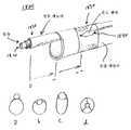
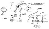
도 1a는 생체 내 수술 처치용 장치(100)를 설명한다. 장치(100)는 기기(115)를 포함한다. 기기(115)는 임상의(예컨대, 외과 의사)에 의해 파지되도록 구성될 수 있고 에너지 공급부(105)를 포함한다. 에너지 전달 구성 요소(110)가 에너지 공급부(105) 및 기기(115)에 커플링되어 에너지를 치료 부위(도시 생략)에 전달할 수 있다. 용어 "치료 부위(treatment area)"는 환자 몸의 임의의 부분을 포함할 수 있다. 치료 부위의 예는 환자 몸 내에 위치한 간질 목표(interstitial target) 뿐만 아니라 피부 표면의 일부를 포함할 수 있다. 일 실시예에서, 에너지 전달 구성 요소(110)는 광섬유이다. 에너지 전달 구성 요소(115)는 기기(115) 및 슬리브(130)를 통과하여 팁(135)에 도달된다. 시술 중, 슬리브(130)에 의해 덮인 에너지 전달 구성 요소(110)의 부분이 치료 부위에 가해진다. 장치(100)는 관성 가속도를 측정하기 위해 기기(115)에 커플링된 가속도계(120)를 더 포함할 수 있다. 일 실시예에서, 에너지 전달 구성 요소(110)는 광섬유일 수 있다.1A illustrates an
에너지 공급부(105)는 흡수 에너지, 광 에너지, 무선주파수 에너지, 음(예컨대, 초음파) 에너지 및 전자기 방사 중 적어도 하나를 제공하도록 구성될 수 있다. 일 실시예에서, 에너지 공급부는 레이저광을 포함한다. 레이저광은 레이저 방사를 포함할 수 있다. 그러나 다른 실시예에서, 레이저 방사는 레이저 펄스(예컨대, Nd:YAG 레이저)를 포함한다. 이 실시예에서, 에너지 공급부는 레이저를 포함한다. 일 실시예에서, 무선주파수 에너지는 무선주파수(RF) 펄스를 포함할 수 있다. 그러나 다른 실시예에서 전자기 방사는 자외선(UV) 광을 포함한다.The
펄스가 치료 부위에 전달될 때, 펄스의 파장은 목표에 가해지는 파워량에 대한 주요 성분의 역할을 한다. 예컨대, 1440nm 파장 펄스는 예컨대 동등한 파워의 1320 nm 파장 펄스보다 지방 조직에 의해 더 많이 흡수된다.When the pulse is delivered to the treatment site, the wavelength of the pulse serves as a major component of the amount of power applied to the target. For example, 1440 nm wavelength pulses are absorbed more by adipose tissue than eg 1320 nm wavelength pulses of equivalent power.
특정 실시예에서, 장치(100)는 에너지 전달 구성 요소(110)에 고정되는 가속도계(120)를 포함할 수 있다. 가속도계(120)는 에너지 전달 구성 요소(110)에 대해 고정된 관계로 기기(115)에 장착 또는 내장될 수 있다. 가속도계(120)는 3개의 직교 방향으로 그리고 최소한 일방향으로의 에너지 전달 구성 요소(110)의 움직임을 나타내는 전기 신호를 생성한다. 가속도계(120)로부터 전기 신호는 에너지 공급부(105)를 제어하는 프로세서(125)에 전송될 수 있어서, 에너지 공급부(105)의 작동이 기기(115)의 동작에 의해 적어도 부분적으로 제어된다.In certain embodiments,
특정 실시예에서, 프로세서(125)는 기기(115)[및 그에 따라, 에너지 전달 구성 요소(110)]가 움직일 때에만 에너지 전달 구성 요소(110)가 작동되도록 프로그램될 수 있다. 가속도계(120)가 기기(115) 및 에너지 전달 구성 요소(110)가 정지 상태임을 나타낼 때, 에너지 공급부(105)의 출력이 종료된다. 이로 인해, 에너지 전달 구성 요소(110)가 최적량 이상의 에너지가 치료 부위의 동일 부분에 연거푸 전달하는 것을 방지하여, 바람직하지 못한 열적 손상을 막을 수 있기 때문에 안전 기능이 제공된다. 또한, 일 실시예에서 장치(100)의 안전 기능은 적어도, 기기(115)가 임계 최소 속도 이하로 가동될 때에 경고 피드백을 제공하는 제어를 포함할 수 있다. 대안으로서 또는 이러한 안전 기능과 조합되어, 장치(100)는 에너지 전달 구성 요소(110)가 임계 최소 속도 이하로 가동될 때에 에너지 공급부(105)의 기능을 정지시키는 제어를 포함할 수 있다.In certain embodiments,
특정 실시예에서, 에너지 공급부는 펄스화될 수 있는 비임을 방사한다. 예컨대, 에너지 공급부가 레이저광을 전달하면, 에너지 공급부는 레이저 펄스율(rate of a laser pulse)을 제어할 수 있다. 에너지 공급부는 치료 부위로 유도되는 전체 에너지량을 제어하기 위해 하나 이상의 파라미터를 조작하도록 형성된다. 일 실시예에서, 에너지 공급부는 펄스당 파워, 펄스 지속시간(pulse duration), 펄스 반복률(pulse repetition rate) 또는 이들 조합을 제어할 수 있다. 치료 부위로 유도되는 전체 파워를 지속 시간 동안 일정하게 유지하면서, 에너지 공급부는 펄스당 파워, 펄스 지속시간, 펄스율 또는 이들 조합을 증가 또는 감소시키도록 형성된다. 일 실시예에서, 에너지 공급부는 가속도계에 의해 제공된 피드백에 응답하여 각각의 에너지 펄스의 펄스들을 발생하는 비율(rate)을 제어하도록 구성된 제어 시스템을 또한 포함한다. 따라서, 저속으로 가동하는 장치(및 그에 따라, 에너지 전달 구성 요소)는 치료 부위로 유도되는 에너지를 더 적게 전달할 것이다. 역으로, 고속으로 가동하는 장치는 더 많은 파워를 전달할 것이다. 일 실시예에서, 제어 시스템은 장치가 움직일 때만 모든 3개의 축으로의 장치 움직임에 따라 조절되는 파워로 에너지 펄스를 방사하도록 구성될 수 있다. 다른 실시예에서, 에너지 공급부는 펄스의 파장, 에너지 전달 구성 요소의 속도, 치료 부위의 조직, 플루언스 설정(fluence setting), 전파 거리 또는 이들 조합에 대한 에너지 펄스율을 제어할 수 있다.In certain embodiments, the energy supply emits a beam that can be pulsed. For example, when the energy supply unit delivers the laser light, the energy supply unit may control the rate of a laser pulse. The energy supply is configured to manipulate one or more parameters to control the total amount of energy directed to the treatment site. In one embodiment, the energy supply may control power per pulse, pulse duration, pulse repetition rate, or a combination thereof. The energy supply is configured to increase or decrease power per pulse, pulse duration, pulse rate, or a combination thereof, while maintaining a constant overall duration of power directed to the treatment site. In one embodiment, the energy supply also includes a control system configured to control the rate of generating pulses of each energy pulse in response to feedback provided by the accelerometer. Thus, devices operating at low speed (and hence energy delivery components) will deliver less energy directed to the treatment site. Conversely, a device running at high speed will deliver more power. In one embodiment, the control system may be configured to emit energy pulses at a power that is adjusted according to the device movement in all three axes only when the device moves. In other embodiments, the energy supply may control the energy pulse rate for the wavelength of the pulse, the speed of the energy delivery component, the tissue at the treatment site, the fluence setting, the propagation distance, or a combination thereof.
특정 실시예에서, 장치는 치료에 반응하는 치료 부위의 반응을 검출하도록 에너지 전달 구성 요소에 결합된 검출기를 포함한다. 일 실시예에서, 센서가 유도되는 에너지에 반응하여 치료 부위의 물리적 변화를 측정하도록 에너지 전달 구성 요소에 커플링될 수 있다. 다른 실시예에서, 검출기는 에너지 전달 구성 요소를 통해 치료 부위로 다시 전송된(transmitted back) 방사를 검출하도록 에너지 전달 구성 요소에 커플링될 수 있다. 예컨대, 검출기는 에너지 펄스의 역방향으로 치료 부위로부터 에너지 전달 구성 요소의 하방으로 이동하는 근적외선 방사를 검출한다. 검출된 근적외선 방사는 치료 부위의 조직의 온도를 모니터링하고 에너지 공급부의 작동을 조정하는데 이용될 수 있다. 그러나 다른 실시예에서, 장치는 조직의 온도가 미리 설정된 온도를 초과하는 것을 검출된 방사가 나타날 때 경고를 보내도록 프로그램될 수 있다. 장치는 조직의 온도가 미리 설정된 온도를 초과하는 것을 검출된 방사가 나타날 때 에너지 공급부의 작동을 금지하도록 추가로 프로그램될 수 있다. 예컨대, 에너지 공급부는 펄스 모드로 작용되고, 치료 부위로부터의 근적외선 방사는 연속적인 치료 펄스들 사이의 지연 시간 동안 검출된다. 연속적인 웨이브 공급부(wave source)에 대해서도, 치료 비임 및 진단 비임이 조절될 수 있어, 연속적인 웨이브 치료 비임의 듀티 사이클이 1(unity)에 근접되었다.In certain embodiments, the device includes a detector coupled to the energy delivery component to detect a response of the treatment site responsive to the treatment. In one embodiment, the sensor may be coupled to an energy delivery component to measure the physical change of the treatment site in response to the induced energy. In another embodiment, the detector may be coupled to the energy delivery component to detect radiation transmitted back through the energy delivery component to the treatment site. For example, the detector detects near-infrared radiation that travels from the treatment site down the energy delivery component in the reverse direction of the energy pulse. The detected near infrared radiation can be used to monitor the temperature of the tissue at the treatment site and adjust the operation of the energy supply. However, in other embodiments, the device may be programmed to alert when a detected radiation appears that the temperature of the tissue exceeds a preset temperature. The device may be further programmed to inhibit the operation of the energy supply when the detected radiation appears that the temperature of the tissue exceeds a preset temperature. For example, the energy supply is operated in pulsed mode, and near-infrared radiation from the treatment site is detected during the delay time between successive treatment pulses. Even for a continuous wave source, the treatment beam and diagnostic beam can be adjusted so that the duty cycle of the continuous wave treatment beam is close to unity.
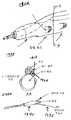
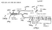
도 2는 본 발명의 장치가 적용되는 방법을 도시한다. 장치(200)는 환자의 피부 상에 만들어진 절개부(210)를 통해 치료 부위(205)(예컨대, 지방 조직)로 삽입된다. 에너지 전달 구성 요소(215)가 치료 부위(205) 내로 더 삽입되고 추가로 이동될 때, 에너지 전달 구성 요소(215)는 하나 이상의 연속 펄스(sequential pulse)를 치료 부위(205)로 사전에 결정된 비율로 유도하도록 구성된다. 시술 중, 에너지 전달 구성 요소(215)의 팁(220)에 바로 인접한 조직 내에서 다량의 흡수 및 가열이 발생된다. 의사가 치료 부위(205)에서 장치(200) 및 그에 따라 에너지 전달 구성 요소 장치(215)를 전후로 이동시킴에 따라, 에너지 공급부(도시 생략)는 하나 이상의 연속 펄스를 방사시킴으로써, 에너지를 제공하고 조직 세포(예컨대, 지방 세포)를 분산 및 파열시킨다.2 shows how the apparatus of the present invention is applied. The
특정 실시예에서, 에너지 공급부는 에너지 전달 구성 요소(215)의 위치에 대해 치료 부위(205)로 유도되는 에너지량을 조절하도록 구성된다. 다른 실시예에서, 에너지 공급부는 치료 부위(205) 내의 물리적 위치에 전달되는 에너지량에 관하여 가속도계(230)에 의해 제공되는 피드백과 관련하여 치료 부위(205)로 유도되는 에너지량을 조정하도록 형성된다.In certain embodiments, the energy supply is configured to adjust the amount of energy directed to
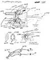
일 실시예에서, 도 3a 및 도 3b에 도시된 바와 같이, 장치(300)는 레이저/수술 핸드피스(310) 내에 위치된 3축 가속도계(305)와, 가속도를 조작자에 대한 속도 및/또는 위치 피드백으로 변환하고 치료 부위로 유도되는 에너지 출력 또는 파워를 조종하는 알고리즘을 갖도록 형성되는 변환기 처리 회로(315, translator processing circuit)를 포함한다. 처리 회로(315)는 가속도계(305)에 커플링되고 치료 부위(도시 생략)로 유도되는 에너지의 선량 측정을 결정한다. 용어 "선량 측정"(dosimetry)은 에너지 노출에 기인한 조직 또는 물질(matter) 내의 에너지 선량의 계산을 말한다. 이와 같이, 속도 및/또는 위치 피드백과 관련하여, 장치(300)는 파워 및 치료 부위로 유도되는 에너지량을 제어할 수 있다.In one embodiment, as shown in FIGS. 3A and 3B, the apparatus 300 includes a three-axis accelerometer 305 located within the laser / surgical handpiece 310, and the acceleration is measured using a velocity and / or position relative to the operator. And a translator processing circuit (315) configured to have an algorithm that translates into feedback and steers energy output or power directed to the treatment site. The processing circuit 315 is coupled to the accelerometer 305 and determines the dose measurement of the energy directed to the treatment site (not shown). The term “dosimetry” refers to the calculation of the energy dose in a tissue or matter due to energy exposure. As such, with respect to velocity and / or position feedback, the device 300 may control the amount of energy directed to the power and treatment site.
특정 실시예에서, 본 발명의 장치는 가속도계로부터의 피드백을 처리하고 치료 부위로 유도되는 에너지량을 제어하도록, 가속도계에 커플링되는 프로세서를 포함한다. 일 실시예에서, 장치는 파워 대 속도 애플리케이션을 포함한다. 이 애플리케이션에서, 치료 부위로 유도되는 파워가 속도 피드백과 관련하여 제어된다. 가속도계는 1축, 2축 또는 3축 속도 피드백을 얻도록 필터링되고 스케일링되고 적분된 출력을 제공한다. 속도 피드백이 2축 또는 3축에 대해 제공될 때, 정적 가속도가 차단되고 단지 동적 가속도 신호만이 에너지 전달 구성 요소에 의해 감지되도록 가속도계(305) 출력의 직류(DC) 성분이 필터링될 수 있다. 이와 같이, 가속도계(305)의 직류(DC) 성분이 차단될 때, 처리 회로(315)는 + 크기 또는 - 크기의 속도 중 하나를 포함하는, 속도에 대한 전체 값을 제공하도록 동적 가속도를 축적한다.In certain embodiments, the apparatus of the present invention includes a processor coupled to the accelerometer to process feedback from the accelerometer and to control the amount of energy directed to the treatment site. In one embodiment, the device includes a power to speed application. In this application, the power directed to the treatment site is controlled in relation to the velocity feedback. Accelerometers provide filtered, scaled, and integrated outputs to get mono, bi, or triaxial velocity feedback. When velocity feedback is provided for two or three axes, the direct current (DC) component of the accelerometer 305 output can be filtered so that static acceleration is blocked and only dynamic acceleration signals are sensed by the energy transfer component. As such, when the direct current (DC) component of the accelerometer 305 is interrupted, the processing circuit 315 accumulates dynamic acceleration to provide an overall value for velocity, including either magnitude of plus magnitude or minus magnitude. .
변환기 처리 회로(315)는 아날로그 및 디지털 소자 모두를 포함한다. 가속도계(305)에 의한 속도 피드백의 3개 채널이 도 4에 도시된 바와 같이, 조절 가능한 게인 입력 증폭기가 후속되는 (예컨대, ~0.25Hz 컷오프를 갖는) DC 차단 고역 통과 필터와 같은 필터를 통해 변환기 처리 회로(315)에 제공된다. 또한, 입력 증폭기는 오프셋될 수 있어, 필터링된 가속도 신호는 양극 양방향 가속도 피드백이 가능하게 된다. 이 수단들을 통해, 중력에 의한 일정하거나 정적인(static) DC 가속도가 차단되고, 동적이거나 가변 가속도가 가속도계로 통과되어 스케일링 및 적분되어 속도 피드백을 얻는다. 또한, 각도 또는 도 3에 300으로 표시된 것과 같은 장치의 배향에 있어서의 변화로 인해, 정적 중력 가속도 벡터는 3축 모두의 사이에 재분배되어 가속도 신호로 재분배되는데, 이는 상기 신호가 중력에 대한 3축 기준 프레임의 각도에 따라 결정되기 때문이다.Converter processing circuit 315 includes both analog and digital elements. Three channels of velocity feedback by accelerometer 305 are shown in FIG. 4, followed by a filter such as a DC blocking high pass filter (eg, with a ~ 0.25 Hz cutoff) followed by an adjustable gain input amplifier. Provided to the processing circuit 315. In addition, the input amplifiers can be offset such that the filtered acceleration signal enables bi-directional acceleration feedback. Through these means, constant or static DC acceleration due to gravity is blocked, and dynamic or variable acceleration is passed through the accelerometer to scale and integrate to obtain speed feedback. Also, due to a change in angle or orientation of the device as indicated by 300 in FIG. 3, the static gravitational acceleration vector is redistributed between all three axes to redistribute the acceleration signal, which causes the signal to be triaxial relative to gravity. This is because it is determined according to the angle of the reference frame.
파워 대 속도 애플리케이션 중 특정 실시예에서, 가속도계는 조합된 3축 합성 속도 피드백을 제공하도록 구성된다. 따라서, 치료 부위로 유도되는 파워 출력은 조합된 속도 피드백을 기초로 스로틀되거나 조절될 수 있다. 각 속도 신호는 상이한 축들을 따르는 속도를 나타내므로, 3개의 축으로부터의 속도값을 단순히 더하는 것은 불가능하다. 예컨대, X축 방향으로의 음의 속도값은 Y축 또는 Z축 방향으로의 양의 속도값으로부터 감산될 것이다. 따라서, 처리를 단순화하기 위해, 본 발명의 가속도계는 도 5에 도시된 바와 같이 각 축에서 독립적으로 절대 속도값을 취한 후 모든 축으로부터의 상기 절대값을 합산하여 준(quasi) 속도 합계값을 제공하도록 구성될 수 있다. 도 5는 본 발명의 장치가 조합된 3축 합성 속도 피드백을 제공하는 방법의 일예를 설명한다. 단계 505x, y, z에서, 각 축으로부터의 가속도 신호가 측정된다. 단계 510x, y, z 및 단계 515x, y, z에서, 입력 증폭기와 가속도 신호는 오프셋된 후, 적분되어, 속도값을 생성한다. 그 후, 각 축으로부터의 속도값은 단계 520x, y, z에서 절대값으로 변환된다. 단계 525x, y, z에서, 속도에 대한 각각의 절대값들은 가중되고(weighted) 더해져서 각각 조합된 3축 합성 속도 피드백을 제공한다. 예컨대, X축에 대한 속도값에 대한 절대값은 가장 큰 가중치를 받아 조합된 3축 합성 속도 피드백에 85%를 기여하는 반면에, Y축 및 Z축의 값은 각각 15% 및 5%로 가중된다. 각 축은 소정의 시술시 장치에 대한 운동의 주축을 편의시키거나 강조하도록 상이하게 증폭될 수 있다. 따라서, 일 실시예에서, X축은 지방 분해와 같은 시술의 주요 스트로크를 따르지만, 가속도계에 의한 Y축 및 Z축 센서로부터의 측면 및 깊이 가속도는 조합된 3축 합성 속도 피드백에 대해 더 적게 기여한다. 지방 분해에 대해, X축으로의 속도는 조합된 3축 합성 속도 피드백의 80%까지, Y축으로의 속도는 15%까지, 그리고 Z축의로의 속도는 5%까지 기여할 수 있다. 선택된 플루언스(파워 출력)를 100% 달성하기 위해, 3축 모두에서의 속도의 절대값이 서로 더해지고, 그 합계는 속도 임계값에 대한 100% 플루언스를 초과해야 한다. 조합된 3축 합성 속도 피드백이 100% 임계값보다 작으면, 파워 출력은 속도에 대해 선형으로 감소한다.In certain embodiments of power to speed applications, the accelerometer is configured to provide combined triaxial synthesized speed feedback. Thus, the power output directed to the treatment site can be throttled or adjusted based on the combined speed feedback. Since each speed signal represents a speed along different axes, it is impossible to simply add speed values from three axes. For example, the negative speed value in the X axis direction will be subtracted from the positive speed value in the Y axis or Z axis direction. Thus, to simplify the process, the accelerometer of the present invention takes an absolute speed value independently on each axis as shown in FIG. 5 and then adds the absolute values from all axes to provide a quasi speed sum value. It can be configured to. 5 illustrates one example of a method for providing combined three-axis synthesis velocity feedback of the apparatus of the present invention. In steps 505x, y, z, acceleration signals from each axis are measured. In steps 510x, y, z and 515x, y, z, the input amplifier and the acceleration signal are offset and then integrated to produce a velocity value. The velocity values from each axis are then converted to absolute values in steps 520x, y, and z. In steps 525x, y, z, the respective absolute values for velocity are weighted and added to provide combined triaxial synthesis velocity feedback, respectively. For example, the absolute value for the velocity value for the X axis contributes 85% to the combined three-axis synthesis velocity feedback under the highest weight, while the values for the Y and Z axes are weighted to 15% and 5%, respectively. . Each axis may be amplified differently to facilitate or emphasize the major axis of motion relative to the device during a given procedure. Thus, in one embodiment, the X axis follows the main stroke of the procedure, such as lipolysis, but the lateral and depth accelerations from the Y and Z axis sensors by the accelerometer contribute less to the combined three axis synthesis velocity feedback. For lipolysis, the velocity in the X axis can contribute up to 80% of the combined triaxial synthesis rate feedback, the velocity in the Y axis up to 15%, and the velocity in the Z axis up to 5%. In order to achieve 100% of the selected fluence (power output), the absolute values of the speeds in all three axes are added together and the sum must exceed 100% fluences for the speed threshold. If the combined three-axis synthesis speed feedback is less than 100% threshold, the power output decreases linearly with speed.
특정 실시예에서, 파워 대 속도 피드백 애플리케이션은 에너지 공급부(예컨대, 도 2에서 도면부호 215로 표시된 부품)를 제어하여 방향 기초 파워 출력 루틴(direction-based power output routine)에 의해 치료 부위로 에너지를 전달하는 프로세서를 포함할 수 있다. 방향 기초 파워 출력 루틴이 실행되면, 에너지 공급부는 본 발명의 장치가 이동하는 방향에 대해 수정된 양의 에너지를 보낸다. 이러한 프로세서는 치료 부위 부분에 에너지를 고르게 전달하기 위해 적용된다. 예컨대, 도 6a에 도시된 바와 같이, 전방 스트로크(605) 동안, 전체 스트로크 에너지의 67%가 투입된다. 도 6b에서, 복귀 스트로크(610)는 전체 파워의 나머지 33%를 투입한다. 후속 샷 전에 약간의 냉각/열 분산 시간이 허용된다는 것이 아이디어이다. 그 결과, 치료 부위 부분 전체에 걸쳐 더욱 고른 에너지 분산을 제공하면서 치료 부위(615)에 대한 열 충격(급격한 ΔT)을 감소시킨다. 또한, 방향 기초 파워 출력 루틴은 좌우 스트로크(side-to-side stroke)에 적용될 수 있다.In a particular embodiment, the power-to-speed feedback application controls the energy supply (eg, the part indicated by reference numeral 215 in FIG. 2) to deliver energy to the treatment site by a direction-based power output routine. It may include a processor. When the direction based power output routine is executed, the energy supply sends a modified amount of energy relative to the direction in which the device of the invention moves. Such a processor is applied to evenly deliver energy to the treatment site portion. For example, as shown in FIG. 6A, during the
파워 대 속도 애플리케이션에 의해, 임상의는 에너지 전달 구성 요소가 이동하는지 여부와 얼마나 빨리 이동하는지를 알 수 있지만, 임상의는 에너지 전달 구성 요소가 이동하고 곳을 정확하게 알 수는 없다. 예컨대, 임상의는 반복적으로 치료 부위의 처치된 부분으로 복귀(예컨대, Y축 및 Z축으로의 속도는 없이 단지 X축을 따라 앞뒤로 이동)할 수 있다. 이 경우, 속도 피드백은 X축 속도가 100% 플루언스 한계에 대한 최소 속도를 초과하는 한 최대 파워 출력을 허용한다. 프로세서 또는 변환기 처리 회로의 일 실시예에서, 프로세서 또는 변환기 처리는 에너지 전달 구성 요소의 속도와 관련하여 치료 부위로 유도되는 파워를 제한하는 알고리즘으로 구성된다. 이런 알고리즘에 의해, 안전성이 크게 향상된다. 과도한 드웰 시간(dwell time)으로 의한 손상이 쉽게 방지되고, 파워 대 속도 애플리케이션을 갖는 본 발명의 장치에 의한 최적의 템포를 위한 조작자에 의한 습득의 용이성이 향상된다. 안정성 측정을 위한 다른 실시예에서, 본 발명의 장치는 치료 부위 및/또는 장치의 다양한 조건을 나타내는 오디오 피드백을 구비할 수 있다. 오디오 피드백은 예컨대, 파워의 출력, 치료 부위의 일부에서의 과도한 온도 상승, (예컨대, 프로브/도핑 비임 전송 수단 및/또는 반사율 광검출기에 의해 판정되는 것과 같은) 목표하지 않은 조직의 접근 검출, 그리고 불리한 조건(예컨대, 출혈, 연소)을 나타낼 수 있다.With power-to-speed applications, the clinician can know if and how fast the energy delivery component is moving, but the clinician cannot know exactly where the energy delivery component is moving. For example, the clinician may repeatedly return to the treated portion of the treatment site (eg, only move back and forth along the X axis without velocity to the Y and Z axes). In this case, velocity feedback allows for maximum power output as long as the X-axis velocity exceeds the minimum velocity for the 100% fluence limit. In one embodiment of the processor or transducer processing circuit, the processor or transducer processing consists of an algorithm that limits the power drawn to the treatment site with respect to the speed of the energy delivery component. By this algorithm, safety is greatly improved. Damage due to excessive dwell time is easily prevented, and the ease of learning by the operator for optimum tempo by the apparatus of the present invention with power to speed applications is improved. In another embodiment for measuring stability, the device of the present invention may be provided with audio feedback indicative of the treatment site and / or various conditions of the device. Audio feedback may include, for example, the output of power, excessive temperature rise at a portion of the treatment site, access detection of undesired tissue (eg, as determined by probe / doping beam transmission means and / or reflectance photodetectors), and Adverse conditions (eg, bleeding, burning) may be indicated.
특정 실시예에서, 파워 대 속도 애플리케이션은 파워 제한 알고리즘을 실시하는 프로세서를 더 포함한다. 알고리즘은 치료 부위의 단위 체적당 에너지(energy/unit volume)가 안전 열 한계를 초과하지 않도록 파워 출력을 제한 또는 스로틀한다. 파워가 얼마나 안전한가를 결정하는 변수들은, 파장, 파워 설정, 조직 유형(예컨대, 조직에 의한 흡수율), 전파 거리 및 반복률 중 적어도 하나와 관련된다. 예컨대, 도 6에 도시된 바와 같이, 기본 곡선은 1Hz 설정에 비해 2Hz 설정에 대해 두 배인 최소 속도를 요구하는데 이는 2Hz 설정에서 파워 출력이 2배이기 때문이다. 각각의 반복률에 대해 상이한 기울기가 도 8에 나타난다. 도 8은 펄스의 반복률 및/또는 치료 부위로 유도되는 파워가 장치의 속도와 관련하여 조절된다는 것을 나타낸다. 최소 속도 곡선은 가해지는 에너지, 조직 흡수율, 냉각 시간 및 핸드피스 이동 속도 중 적어도 하나의 예측값을 기초로 과도한 조직 온도 상승을 방지하기 위한 것이다. 또한, 기울기 수정 인자는 각각의 조직 유형 및/또는 각각의 파장으로부터 얻어질 수 있다.In a particular embodiment, the power to speed application further includes a processor that implements a power limiting algorithm. The algorithm limits or throttles the power output such that the energy / unit volume of the treatment site does not exceed the safety thermal limit. Variables that determine how safe the power is associated with at least one of wavelength, power setting, tissue type (eg, absorption by tissue), propagation distance, and repetition rate. For example, as shown in FIG. 6, the basic curve requires a minimum speed that is twice that of the 2 Hz setting compared to the 1 Hz setting because the power output is doubled at the 2 Hz setting. Different slopes are shown in FIG. 8 for each repetition rate. 8 shows that the repetition rate of the pulses and / or power directed to the treatment site is controlled in relation to the speed of the device. The minimum velocity curve is to prevent excessive tissue temperature rise based on the predicted value of at least one of applied energy, tissue absorption, cooling time and handpiece movement speed. In addition, the slope correction factor may be obtained from each tissue type and / or each wavelength.
파워 제한 알고리즘의 일 실시예에서, 장치는 에너지 전달 구성 요소가 치료 부위 내로 도입하는 지점으로부터 미리 정해진 거리 내에 있을 때 방사된 에너지의 크기를 조절하도록 구성되는 에너지 공급부를 포함할 수 있다. 다시 도 2를 참조하면, 팁(220)이 이미 처치된 물리적 위치로 재방문할 때, 에너지 공급부(도시 생략)는 이미 처치된 부분이 연소되지 않고 적절한 크기의 에너지로 최적으로 처치되도록 치료 부위의 각 부분으로 전달되는 에너지의 크기를 조절하도록 구성된다. 예컨대, 팁(220)은 절개부(210)로부터 비교적 멀리에 있는 물리적 위치(240) 내의 부분보다 절개부(210)에 가까운 물리적 위치(235)에서의 부분과 더 자주 접촉하게 된다. 따라서, 팁(220)이 접촉할 때마다 물리적 위치(235)의 일부가 동일한 크기의 에너지로 펄스가 가해지면, 이 부분들은 연소되거나 또는 결국 과도하게 처치될 것이다. 이런 형태의 절개부(210) 부근의 부분에 대한 에너지의 바람직하지 않은 과다 노출을 방지하기 위해, 에너지 공급부는 절개부(210)로부터 미리 정해진 거리 내의 부분에 전달되는 에너지 크기를 조절하고 유도되는 에너지 크기를 제한하도록 구성된다.In one embodiment of the power limiting algorithm, the apparatus may include an energy supply configured to adjust the magnitude of the radiated energy when within the predetermined distance from the point at which the energy delivery component is introduced into the treatment site. Referring back to FIG. 2, when the
파워 대 속도 애플리케이션의 특정 실시예에서, 본 발명의 장치는 도 7에 도시된 바와 같이 오프셋 기구를 더 포함할 수 있다. 일 실시예에서, 장치는 레이저 광을 포함하고, 레이저 광은 장치의 이동 속도에 의해 직접 스로틀 될 수 있다. 오프셋 기구는 도 9에 제공된 속도 대 파워 그래프로부터 어느 정도의 편향을 허용한다. 예컨대, 이는 특정 시술에 적합하도록 하드코드된 안전 한계 내에서 에너지 대 속도 기울기를 미세하게 조정하는 능력을 임상의에게 제공한다. 예컨대, 장치는 곡선(905)으로 표시된 바와 같이 1Hz 반복률 설정에 대해 파워 대 속도 애플리케이션 내에서 증가하는 파워에 음의 오프셋을 가하도록 구성될 수 있다. 반대로, 양의 오프셋이 가해질 때, 장치는 곡선(910)으로 표시된 바와 같이 더 작은 파워를 방사하도록 구성된다. 그리고 레이저는 이동 속도가 허용되도록 선택된 파워의 백분율을 결정하도록 속도와 관련하여 파워를 감소시킨다. 명백하게, 선택된 파워는 장치의 이동 속도와 무관하게 절대 초과되지 않는다.In certain embodiments of power to speed applications, the apparatus of the present invention may further include an offset mechanism as shown in FIG. In one embodiment, the device comprises laser light, which can be throttled directly by the speed of movement of the device. The offset mechanism allows some deflection from the speed versus power graph provided in FIG. For example, this gives the clinician the ability to fine tune the energy to velocity gradient within hardcoded safety limits to suit a particular procedure. For example, the device may be configured to apply a negative offset to increasing power within a power versus speed application for a 1 Hz repetition rate setting as indicated by
파워 대 속도 파워 제한 알고리즘에 대한 대안은 파워 대 위치차(difference-in-position, Δ-position) 애플리케이션이다. 이 경우, 변환 벡터(translation vector)는 3축 모두에서 위치차로부터 계산된다. 이 변환 벡터는 3차원 공간을 통한 절대 속도 및 거리를 규정한다.An alternative to the power-to-speed power limiting algorithm is power-difference-in-position (Δ-position) applications. In this case, the translation vector is calculated from the position difference on all three axes. This transform vector defines the absolute velocity and distance through the three-dimensional space.
파워 대 위치차 파워 애플리케이션은 더욱 정밀한 제어와 정확한 단위 체적당 에너지 온도 상승 제한을 허용한다. 특히, 장치의 절대 위치와 파장 및 파워 출력(예컨대, 지방 조직 흡수율)을 동시에 추적함으로써, 매우 양호한 국부적 온도 상승의 예측이 달성될 수 있다.Power vs. positional power applications allow more precise control and accurate limit of energy temperature rise per unit volume. In particular, by simultaneously tracking the absolute position and wavelength of the device and the power output (eg, fat tissue absorption), a very good prediction of local temperature rise can be achieved.
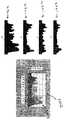
3개의 개별 위치 추적을 플로팅 함으로써, 가속도계를 사용하여 3축 모두에서 독립적으로 측정된 가속도는 도 10에 도시된 바와 같이 간질 목표의 3차원 공간 내에 정확한 위치를 산출하도록 두 번 적분된다. 3축 내의 위치 트랙은 3차원 데카르트 평면(1000) 상에 플로팅되고 위치 설정된다. 3축은 한 점에서 모이고, 3축의 수렴 플로팅은 목표 부위 내에 본 발명의 장치의 에너지 전달 구성 요소의 실제 위치(1005)를 산출한다.By plotting three separate position tracks, the acceleration measured independently in all three axes using the accelerometer is integrated twice to yield the correct position within the three-dimensional space of the epilepsy target, as shown in FIG. Position tracks in three axes are plotted and positioned on a three-dimensional
절대 위치에 로킹된 각각의 샷의 위치는 치료 부위의 맵을 생성함으로써 과정 내내 기록될 수 있다. 조작자에 대한 단순한 픽셀 암화 디스플레이(pixel darkening display)는 빠지거나 처치되지 않은 부위의 신속한 확인을 허용한다. 이 피드백은 더욱 고르게 분포된 에너지 치료를 허용한다.The location of each shot locked in the absolute position can be recorded throughout the course by generating a map of the treatment site. A simple pixel darkening display for the operator allows for quick identification of missing or untreated areas. This feedback allows for evenly distributed energy treatment.
파워 대 위치차 애플리케이션의 특정 실시예에서, 치료 부위는 환자의 피부의 표면부(예컨대, 얼굴)이다. 도 10에 도시된 간질 목표의 3차원 맵과 유사하게, 3차원 국소 해부 맵은 피부 표면부의 피크(peak)와 밸리(valley)를 표시한다. 치료 전에, 피부 표면부의 사진을 기초로 2차원 내지 3차원 알고리즘을 사용하여 3차원 국소 해부 맵이 만들어진다. 국소 해부 맵 상의 각 점은 가해지는 에너지(Ein), 흡수율 또는 전파 거리와 시간 상수 및 조직 유형과 관련된 연속성 중 적어도 하나를 고려하는 축적물을 나타낸다. 치료 중, 3차원 국소 해부 맵은 에너지 전달 구성 요소의 위치, 각 부분으로 유도되는 에너지 크기, 그리고/또는 각 부분에 의해 흡수된 에너지 크기를 나타내도록 구성된다.In certain embodiments of the power versus position difference application, the treatment site is a surface portion (eg, a face) of the patient's skin. Similar to the three-dimensional map of the epilepsy target shown in FIG. 10, the three-dimensional local anatomical map displays peaks and valleys of the skin surface. Prior to treatment, a three-dimensional local anatomical map is made using two- to three-dimensional algorithms based on a photograph of the skin surface. Each point on the local anatomical map represents an accumulation that considers at least one of the applied energy (Ein), absorption or propagation distance and time constant and continuity associated with tissue type. During treatment, the three-dimensional local anatomical map is configured to indicate the location of energy delivery components, the magnitude of energy directed to each portion, and / or the magnitude of energy absorbed by each portion.
파워 대 위치차 애플리케이션의 특정 실시예에서, 치료 부위로 유도되는 파워는 3축 모두에서의 위치에 있어서의 차이로부터 변환이 계산되는 위치 피드백과 관련하여 제어된다. 이 변환 벡터는 3차원 공간 내에서의 거리와 절대 속도를 규정한다. 위치차 피드백 적용을 위해 가속도계에 결합된 변환기 처리 회로는 중력이 더 이상 무시될 수 없다는 점에서 속도 피드백과 상이하다. 오히려, 중력 벡터의 방향은 장치 내의 가속도계에 결합된 자이로(예컨대, 도 3에 320으로 표시된 부품)의 사용에 의해 또는 수학적으로 결정되어야 한다. 자이로의 이점은 시술의 처음에 일단 정렬하면 자이로는 정밀한 경사 피드백을 제공할 수 있고, 이는 변환기가 중력을 빼고 각각의 축으로부터의 가속도를 독립적으로 고려하여 속도 및 위치를 얻는 것을 허용한다는 것이다. 자이로는 또한 다른 가속도계 편류 및 오프셋 보상을 허용한다.In a particular embodiment of the power versus position difference application, the power directed to the treatment site is controlled in relation to the position feedback where the transformation is calculated from the difference in position in all three axes. This transform vector defines the distance and absolute velocity in three-dimensional space. Transducer processing circuitry coupled to accelerometers for positional feedback applications differs from speed feedback in that gravity can no longer be ignored. Rather, the direction of the gravity vector must be determined mathematically or by the use of a gyro (eg, the part indicated 320 in FIG. 3) coupled to the accelerometer in the device. The advantage of the gyro is that once aligned at the beginning of the procedure, the gyro can provide precise tilt feedback, which allows the transducer to gain velocity and position by subtracting gravity and taking into account the acceleration from each axis independently. Gyro also allows for other accelerometer drift and offset compensation.
파워 대 위치차 애플리케이션의 일 실시예에서, 이들 위치 피드백값은 3차원 좌표 평면상에 차트화되고, 3축 좌표계 내에 에너지 전달 구성 요소의 위치의 임의의 변경을 나타낼 수 있다. 이러한 위치의 고려는 3차원 좌표 평면 내의 점들 사이의 거리, 점들 사이의 이동 시간 또는 다른 상대적인 위치 데이터를 규정하는 변환 벡터의 계산을 허용하고, 실제 3차원 속도 합계뿐만 아니라 절대 위치를 제공한다. 3차원 좌표 평면의 다른 이점은 오프셋 벡터 및 거리, 임의의 축에 대한 회전 또는 위치 데이터의 미러 이미지 관리를 허용하는 것과 같이 복잡한 작동을 단순화한다는 것이다. 미러 이미지 변환에 대한 요구의 예는 도 1a의 기기(105)와 같은 요소이다. 이 요소는 신체 내에 있는 에너지 전달 구성 요소(110)와 같은 요소에 대해 미러 이미지 좌표 평면 내에서 이동한다.In one embodiment of the power versus position difference application, these position feedback values are charted on a three-dimensional coordinate plane and may represent any change in the position of the energy transfer component within the three-axis coordinate system. This positional consideration allows the calculation of transform vectors that define distances between points in the three-dimensional coordinate plane, travel time between points or other relative position data, and provide absolute positions as well as actual three-dimensional velocity sums. Another advantage of the three-dimensional coordinate plane is that it simplifies complex operations such as allowing offset vector and distance, rotation about any axis or mirror image management of position data. An example of a request for mirror image conversion is an element such as
파워 대 위치차 애플리케이션으로 구성된 알고리즘은 또한 이미 처치된 스폿/위치로의 과도한 에너지의 방사를 제한 또는 방지할 수 있다. 따라서, 임상의는 과도한 열 상승을 방지하기 위해 레이저가 펄스마다 또는 밀리초(millisecond)를 기초로 파워를 스로틀백(throttle back)하는 동안 동일한 조직 섹터를 여러 번 지나갈 수 있다. 임상의가 이전에 처치된 부위의 냉각을 더 적게 허용할수록, 상응하여 결과적으로 더 적은 에너지가 허용된다. 이 실시예는 도 11에 도시되어 있다. 본 발명이 2차원 또는 3차원적으로 작동할 수 있지만, 설명을 위해 도 11은 치료 부위(1100)를 나타내는 2차원 단면 맵만을 도시한다. 임상의가 치료 부위(1100) 내에서 행동을 취함에 따라, 맵은 장치(1140)에 의해 처치되는 부분을 모두 기록하고 도 11에 도시된 것과 유사하게 치료 부위의 영상을 임상의에게 제공한다. 치료 부위(1100)는 챠트화되고 치료 부위 또는 체내 공동을 나타내는 상이한 섹션(1110, 1115, 1120, 1125 및 1130)으로 분할될 수 있다. 스폿/위치(1105, 1106, 1107)는 예컨대 레이저 펄스로 이미 처치된 부분이며, 부분(1135, 1136, 1137)은 처치되어야 할 부분이다. 치료가 진행됨에 따라, 파워 대 위치차 애플리케이션을 기초로 상기 위치로부터 관측하고 있는 임상의는 처치되지 않은 부분(1135, 1136, 1137)으로부터 치료 부위(1100)의 처치된 부분(1105, 1106, 1107)을 쉽게 식별할 수 있다. 따라서, 임상의는 치료 부위(1100)의 처치되지 않은 부분(1135, 1136, 1137)을 처치하도록 장치(1140)를 조작하고 이동시킨다. 처치된 부분(1105, 1106, 1107)의 위치와 더불어, 치료 부위(1100)의 맵은 유도되는 에너지/부위의 크기 및/또는 흡수된 에너지의 크기를 도시한다. 예컨대, 섹션(1130)이 다른 섹션보다 더 큰 레이저 펄스로 처치되면, 맵은 섹션(1130)이 다른 섹션보다 더 큰 파워/부위로 처치되고 임의의 부분은 이미 최적으로 처치되었다는 것을 나타내는 피드백을 제공할 것이다. 일 실시예에서, 치료 부위의 맵은 컬러 코딩(color coding)을 포함할 수 있다. 컬러 코딩은 치료 부위의 일부에 의한 흡수율의 크기와 같은 치료의 효과를 나타낼 수 있다. 컬러 코딩은 또한, 임의의 파장에서 다수의 샷의 펄스에 대해 솔리드 레드 점과, 다른 파장에서 약간의 샷의 펄스에 대해 연한 레드 점과 같이, 방사 펄스의 강도를 나타낼 수도 있다.Algorithms composed of power versus position difference applications can also limit or prevent the emission of excessive energy to the spot / position already treated. Thus, the clinician may pass through the same tissue sector several times while the laser throttles back the power on a pulse or millisecond basis to prevent excessive heat buildup. The less clinicians allow cooling of previously treated sites, the correspondingly less energy is allowed as a result. This embodiment is shown in FIG. Although the present invention may operate in two or three dimensions, for illustration purposes only FIG. 11 shows a two-dimensional cross-sectional map representing the
특정 실시예에서, 파워 대 위치차 애플리케이션으로 구성된 장치는 속도 대 파워 적용으로 구성된 앞서 논의된 것과 유사한 안전 특징부를 포함할 수 있다.In certain embodiments, a device configured for power versus position applications may include safety features similar to those discussed above configured for speed to power applications.
특정 실시예에서, 본 명세서에 논의된 파워 대 위치차 애플리케이션으로 구성된 장치는, 전술한 속도 피드백 적용과 유사하게, 치료 부위 내에 에너지를 고르게 분포시키는 것을 포함한 파워 대 속도 애플리케이션에 대해 논의된 파워 제한 알고리즘 및/또는 프로세서 중 하나 이상을 포함할 수 있다.In a particular embodiment, the device configured with the power versus position difference application discussed herein, similar to the velocity feedback application described above, power limitation algorithms discussed for power to speed applications, including evenly distributing energy within the treatment site. And / or one or more of a processor.
특정 실시예에서, 본 발명의 장치는 펄스를 중첩시키기 위해 고려되는 프로세서를 더 포함한다. 각각의 펄스는 펄스의 파장에 따라 상이한 거리 및 상이한 흡수율로 전파된다. 일련의 펄스가 방사되면, 파장, 흡수율 및 전파 거리는 도 12a 내지 도 12d에 도시된 바와 같이 중첩될 수 있다. 도 12a는 치료 부위(1205) 아래에 삽입되고 에너지(1210, 예컨대 레이저 펄스)를 전달하는 에너지 전달 구성 요소(1201)를 도시한다. 도 12b는 전달된 에너지(1210)로부터의 방사상 온도 상승을 도시하며, 에너지(1210) 원점(origin)에 가장 가까운 원은 약 70℃로 가장 뜨겁고, 가장 먼 원은 약 50℃이다. 도 12c는 일련의 중첩하는 펄스(1225, 1226, 1227)로부터 야기된 핫 스폿(1220, 1221)을 도시한다. 핫 스폿으로 전달된 파워의 크기를 고려할 목적으로, 핫 스폿(1220)에서 흡수되는 최종 열 에너지는 단순히 함께 더해질 수 있다. 일련의 펄스가 다른 파장으로 방사되면, 흡수된 전체 에너지 대 모든 구성 파장의 펄스의 거리는 조직 온도 상승의 정확한 예측을 허용한다. 도 12d는 대응하는 온도 상승 대 거리에 의해 2개의 연속적이고 가깝게 위치하거나 중첩하는 샷(레이저 펄스)을 묘사한다. 개별 샷에 대한 온도의 변화 또는 ΔT는 단열적인 계산에 의해 예측될 수 있고, 파장, 파워, 목표 조직 흡수 및 분산 효과는 목표 조직 내의 방향과 거리에 대한 ΔT의 계산을 허용한다. 최종 조직 ΔT 존이 중첩하는 가깝게 위치된 샷들은 인접하여 전달된 샷으로부터의 예열로 인해 온도가 추가적으로 축적된다. 또한, 거리에 대한 최대 ΔT와 최소 ΔT 사이의 비는 "미분값 ΔTmax"로 정의될 수 있다. 예컨대, 에너지를 축적하고 매우 고른 조직 가열을 위해, 더욱 일관된 조직 가열을 제공하도록 "미분값 ΔTmax"가 최소화되어야 한다.In certain embodiments, the apparatus of the present invention further includes a processor contemplated for superposing the pulses. Each pulse propagates at different distances and at different rates of absorption, depending on the wavelength of the pulse. When a series of pulses are emitted, the wavelength, absorptivity and propagation distance can overlap as shown in FIGS. 12A-12D. 12A shows an
도 13a 내지 도 13c에 도시된 바와 같이, 치료 부위의 일부가 100mJ을 전달하는 1064nm, 1320nm 및 1400nm 에너지 전달 구성 요소(예컨대, 600㎛ 섬유)에 노출될 때의 단열적인 온도 상승은 각각 300㎛ 반경 좌표에서 0.2℃, 0.81℃ 및 20℃이다.As shown in FIGS. 13A-13C, the adiabatic temperature rise when a portion of the treatment site is exposed to 1064 nm, 1320 nm and 1400 nm energy transfer components (eg 600 μm fiber) delivering 100 mJ is 300 μm radius, respectively. 0.2, 0.81 and 20 ° C in the coordinates.
파워 대 위치차 애플리케이션의 특정 실시예에서, 치료 부위는 간질 목표이다. 본 발명의 장치에 커플링되는 가속도계를 사용하면, 체내 부위가 맵핑될 수 있고, 그로 인해 장치가 간질 목표로 안내될 수 있다. 3차원 맵의 일 실시예에서, 정렬이 수행되는 지점이 도 14에 도시된 바와 같이 원점(0x, 0y, 0z)(1405)으로 정의된다. 3차원 맵의 각각의 물리적 지점은 예컨대 레이저 펄스와 같은 에너지 인(Ein)이 물리적 노드(1410)로 유도될 때 어큐뮬레이터에 의해 표현된 물리적 노드의 범위 내에서 흡수된 에너지의 조합 효과를 측정하는 어큐뮬레이터를 포함한다. 화살표(1415, 1416, 1417, 1418, 1419 및 1420)는 간질 목표까지의 Ein의 전파 거리를 나타낸다(Ein 전파의 벡터는 수학적 처리 및 변환을 간략화하도록 3축에 표시된다). 3차원 맵 상의 각 지점은 가해지는 에너지(Ein), 흡수율 또는 전파 거리와 시간 상수 및 조직 유형과 관련된 연속성 중 적어도 하나를 고려하는 축적물을 나타낸다. 화살표를 음영 처리한 그래프는 에너지 크기 대 거리의 플롯(1425)이다. 숫자(+1, +2, +3, -1, -2, -3)는 물리적 노드(1410)로부터의 임의의 거리를 나타내며, +1과 -1이 가장 가깝다. 이들에 있어서, 물리적 노드(1410)에 인접한 +1, -1 이하의 부위는 가장 많은 에너지를 제공받거나 흡수하고, 가장 높은 피크 온도 상승(1430)으로 표시된다. 반대로, 물리적 노드(1410)로부터 가장 먼 부위, 예컨대 +3, -3은 가장 낮은 피크 온도 상승(1435)을 보인다.In certain embodiments of power versus positional applications, the treatment site is an epilepsy target. Using an accelerometer coupled to the device of the present invention, the body parts can be mapped, thereby guiding the device to epilepsy targets. In one embodiment of the three-dimensional map, the point at which alignment is performed is defined as origin (0x , 0y , 0z ) 1405, as shown in FIG. 14. Each physical point of the three-dimensional map measures the combined effect of absorbed energy within the range of physical nodes represented by the accumulator when energy phosphorus (Ein ), such as a laser pulse, is directed to the
특정 실시예에서, 이하에 더 상세하게 설명되는 바와 같이, 도핑 비임을 주입하거나 다른 기술이 사용되어 조직 유형을 판단할 수 있다. 예컨대, (산소 측정 장치에서와 같이) 2개의 상이한 파장의 낮은 파워 광 방출 다이오드를 사용하는 것은 컬러 특정 반사력 또는 리미턴스(remittance)를 식별하는 것을 허용한다. 주요 치료 파장은 오히려 에너지 전달 구성 요소로 다중 송신된 도핑 또는 프로빙 비임(probing beam) 중 하나일 수 있다. 조직은 유형을 기초로 상이한 파장을 반사하기 때문에, 물리적 노드(1410)를 구성하는 조직의 유형은 치료 중 도핑 비임에 의해 확인될 수 있다. 본 발명의 장치가 간질 목표 내에서 조정됨에 따라, 에너지 공급부는 최적의 치료에 알맞은 미리 정해진 양의 에너지를 제공하도록 조직 유형에 따라 자동으로 조절될 수 있다. 또한, 다른 실시예에서, 어큐뮬레이터는 또한 하나 이상의 에너지 샷 후에 물리적 노드(1410)에서의 냉각률을 추적한다. 따라서, 장치가 물리적 노드(1410)로 복귀할 때, 에너지 공급부는 어느 정도 더 많은 치료가 필요한지 그리고 얼마나 많이 필요한지를 판단하도록 냉각률(rate of cooling)을 기초로 조절될 수 있다.In certain embodiments, as described in more detail below, a doping beam can be injected or other techniques can be used to determine tissue type. For example, using low power light emitting diodes of two different wavelengths (as in oxygen measurement devices) allows to identify color specific reflectivity or limit. The main therapeutic wavelength may rather be one of a doped or probing beam multiplexed to the energy transfer component. Because the tissue reflects different wavelengths based on the type, the type of tissue making up the
조직 판별 장치 또는 도핑 비임은 또한 피부에 대한 장치의 위치를 확인할 수도 있다. 섬유가 (아래로부터) 피부에 너무 가깝게 접근하면, 반사율 대 컬러에 있어서의 적절한 변화가 관찰되고 그에 따라 연소를 유발하기 전에 레이저를 차단하는 알고리즘을 허용하거나 조작자에게 경고를 제공한다. 일 실시예에서, 도핑 비임은 에너지 전달 구성 요소의 팁에 위치되며, 조직에 의해 반사되고 센서에 의해 검출되는 비임을 방출한다.The tissue discriminating device or doping beam may also identify the location of the device relative to the skin. If the fiber approaches the skin too closely (from below), an appropriate change in reflectance versus color is observed and thus allows an algorithm to block the laser before triggering combustion or to alert the operator. In one embodiment, the doped beam is located at the tip of the energy delivery component and emits a beam that is reflected by the tissue and detected by the sensor.
본 명세서에 개시된 장치의 실시예는 레이저 또는 광 에너지와 관련된 에너지 공급부를 구비한다. 그러나 이 에너지 공급부는 통상적으로 지방 분해에 사용되는 것과 같은 흡입 에너지로 대체될 수 있다. 흡입 에너지를 갖는 실시예에서, 가속도계는 흡입 에너지 공급부과 소통하고, 그에 따라 흡입 에너지 공급부는 치료 부위로 유도되는 흡입 에너지의 크기를 조절할 수 있다. 기기(도 1에서 115)와 캐뉼러(도 1에서 130)로 이어지는 에너지 전달 구성 요소[즉, 도 1에서 요소(110)]를 갖는 대신에, 캐뉼러만 단독으로 사용되어 치료 부위로부터 원치 않는 신체의 일부 또는 조직을 제거할 수 있다.Embodiments of the devices disclosed herein have an energy supply associated with laser or light energy. However, this energy supply can be replaced with inhalation energy, typically used for lipolysis. In embodiments with inhalation energy, the accelerometer is in communication with the intake energy supply, whereby the intake energy supply can adjust the magnitude of the intake energy directed to the treatment site. Instead of having an energy delivery component (i.e.
본 발명의 특정 실시예에서, 수술 시스템(1500)은 100, 200, 300으로 도시된 기기 또는 흡입 에너지를 갖는 것과 유사한 장치(1510)와, 장치와 통신하는 영상 디스플레이를 포함한다. 일 실시예에서, 영상 디스플레이는 도 3에서 315로 도시된 것과 같은 에너지 전달 구성 요소와 유사한 요소의 위치, 그리고/또는 치료 부위의 물리적 지점에 의해 흡수된 에너지의 크기를 표시한다. 영상 디스플레이의 예는 도 14에 도시된 광 검출기 센서 패드(1505)이다. 광 검출기 센서 패드(1505)는 환자의 치료 부위 위에 위치되는 광 검출기 소자의 매트릭스를 포함하는 박막 시트이다. 일 실시예에서, 센서 패드(1505)는 종래의 실크 스크린 인쇄 프로세스와 같은 임의의 공지 수단을 사용하여 제조될 수 있는 염료계 태양 전지[1520, dye-based solar cell(DBSC)]의 매트릭스를 포함한다. 다른 실시예에서, 센서 패드(1505)는 DBSCs의 매트릭스(예컨대, ~100 1cm×1cm 매트릭스)로 구성된다. DBSCs는 검출 회로 소자(1525)로 신호를 복귀시키도록 소성 재료에 인쇄된 금속화된 전극을 갖는 가요성 소성 재료상에 제조된다. 도 15에 도시된 바와 같이, 센서 패드(1505)는 환자의 처치될 부위 위에 위치되어, 샷 바이 샷(shot-by-shot)을 기초로 발사된 레이저 샷과 팁(1530)의 물리적 지점(1535)을 검출한다. 센서 패드(1505)는 샷이 USB 커넥터와 같은 데이터 커넥터(1540)를 통해 레이저로 다시 발사되는 곳과 팁(1530)의 물리적 지점(1535)을 소통한다. 이 정보는 터치 스크린 디스플레이 상에 디스플레이되어 시술동안 의사를 돕고, 레이저 제어 시스템에 의해 사용되어 임의의 한 위치에 너무 많은 샷이 발사된다면 레이저를 작동하지 않도록 할 수 있다.In certain embodiments of the present invention,
도 15에 도시된 바와 같이, 레이저가 발사됨에 따라, 레이저가 발사된 위치는 하나 또는 작은 그룹의 광 검출기(1535)에 의해 검출되고, 디스플레이를 위해 레이저 제어 시스템으로 다시 x, y, 좌표를 전송한다. 레이저 비임은 또한 발광 다이오드와 같은 하나 또는 여러 개의 낮은 파워 일정 광원에 의해 도핑되어, 치료 도중 팁의 적절한 위치 설정을 위해 임상의에게 다시 팁의 위치를 전달한다. 도 16에 도시된 바와 같이, 도핑 파장은 예컨대 550nm 또는 660nm 또는 이들의 조합일 수 있다. 다수의 파장이 도핑 비임에 사용될 때, 레이저 핸드피스 팁의 깊이는 예컨대, 도핑 비임의 2개의 파장의 다른 분산으로 인해 진폭의 변화를 검출함으로써 판단될 수 있다.As shown in FIG. 15, as the laser is fired, the position at which the laser is fired is detected by one or a small group of
센서 패드(1505)는 사용 후에 위치 변환 회로 소자(1525)로부터 제거되어 폐기되는 일회용 부품이다. 변환 회로 소자(1525)는 연속적인 지방 분해에 사용하기 위해 (도시되지 않은) 새로운 센서 패드에 부착될 수 있다.The
레이저 지방 분해 시스템은 도 17에 도시된 바와 같이 사용자 인터페이스 디스플레이(1700)를 포함할 수 있다. 이 디스플레이(1700)는 펄스 폭 제어(1710), 플루언스 디스플레이(1715) 및 제어 등과 같은 기본적인 레이저 인터페이스 제어(1705)를 포함한다. 또한, 레이저 샷 위치 디스플레이(1700)는 센서 패드 상에 샷이 기록되는 곳[예컨대 도 15의 구성 요소(1505)]과 함께 팁의 현재 위치[예컨대 도 15의 구성 요소(1530)]를 디스플레이할 수 있다. 샷 위치 디스플레이는 또한 바람직하게는 그리드의 컬러-코딩과 같은 것에 의해 그리드를 거쳐 발생되는 치료의 레벨을 표시한다. 이 디스플레이는 의사가 다음 샷을 위한 장치의 위치 설정하는 것을 보조하고, 치료 부위의 임의의 하나의 위치에서의 과도한 처치를 방지하는데 사용될 수 있다.The laser lipolysis system may include a user interface display 1700 as shown in FIG. 17. This display 1700 includes basic laser interface controls 1705, such as pulse width control 1710, fluence display 1715 and control. In addition, the laser shot position display 1700 may display the current position of the tip (eg,
열 감지Heat detection
이하에 상세하게 설명되는 전술한 유형의 열 감지 기술은 단독으로, 또는 다른 센서 정보와 함께 사용된다.The above-described types of thermal sensing techniques described in detail below are used alone or in combination with other sensor information.
온도 센서는 임의의 적절한 방식으로 수술 장치에 장착될 수 있다. 예컨대, 도 18은 섬유 캐뉼러(182) 내에 광섬유(1810)를 포함하는 레이저 지방 제거를 위한 수술 프로브(1800)를 도시한다. 광섬유(1810)는 조직(예컨대, 지방 조직)으로 치료 광을 전달한다. 프로브는 또한 치료 부산물의 제거를 위한 흡입 캐뉼러(1830)를 포함한다. 이 프로브의 특징부는 흡입 캐뉼러에 일체로 된 온도 센서(1840)이다. 온도 센서(1840)는 레이저 섬유 팁으로부터 후방에 설치된다. 전형적인 실시예에서, 이 구성은 조직 온도의 잘못된 판독을 일으키는 캐뉼러(1820) 및 섬유(1810)의 팁의 국부적인 가열을 예방한다.The temperature sensor can be mounted to the surgical device in any suitable manner. For example, FIG. 18 shows a
수술 도중, 레이저 조사되는 부위 내에서 프로브를 고정 상태(일시 정지)로 유지하면서 조직 온도가 판독될 수 있다. 판독을 기초로, 원하는 내부 조직 온도에 도달하도록 더 많은 레이저 에너지 또는 냉각 효과가 가해질 수 있다. 전형적인 적용에서, (예컨대, 프로브가 조직의 내외부로 급속하게 왕복 운동하면) 온도 판독은 변동할 것이다. 이 경우, 온도 판독은 의미 있는 온도를 나타내도록 평균 내어질 수 있다.During surgery, tissue temperature can be read while keeping the probe stationary (paused) within the area irradiated with the laser. Based on the reading, more laser energy or cooling effect can be applied to reach the desired internal tissue temperature. In typical applications, the temperature reading will fluctuate (eg, if the probe reciprocates rapidly in and out of tissue). In this case, the temperature reading can be averaged to indicate a meaningful temperature.
다양한 실시예에서, 임의의 적절한 온도 센서가 다양한 수술 프로브 유형 중 임의의 것에 포함될 수 있다. 예컨대, 도 19는 온도 센서(1920)를 위한 개별적인 스테인리스강 캐뉼러(1910)를 특징으로 하는 레이저 지방 제거용 수술 프로브를 도시한다. 온도 센서(1920)는 캐뉼러(1910)의 팁 내에 있으며, 하나 이상의 와이어(1930)가 캐뉼러(1910)를 통해 핸드피스(1940) 내로 빠져나간다. 와이어(1930)는 핸드피스(1940)의 단부로부터 연장되고, 모니터 또는 처리 유닛에 연결될 수 있다.In various embodiments, any suitable temperature sensor may be included in any of a variety of surgical probe types. For example, FIG. 19 shows a surgical probe for laser fat removal featuring a separate
도 20은 직전에 도시된 실시예와 달리 흡입 캐뉼러를 포함하지 않는 레이저 수술 프로브(2000)의 실시예를 도시하고 있다.20 illustrates an embodiment of a laser
프로브(2000)는 내부 캐뉼러(2020)(예컨대, 표준 600㎛ 캐뉼러)에 위치하여 치료 광을 전달하는 광섬유(2010)를 포함한다. 더 큰 외부 캐뉼러(2030)가 내부 캐뉼러(2020)를 둘러싼다. 온도 센서(예컨대, 열전대 접합부)(2040)가 외부 캐뉼러(2030)의 팁 가까이 위치된다. 센서(2040) 및 그로부터 연장된 연결 와이어는 내부 캐뉼러(2020)로부터 열전기적으로 절연된다. 예컨대, 도면의 하부에 도시된 바와 같이, 센서(2040) 및 와이어는 열전기적 절연재 재킷(2050)에 의해 둘러싸일 수 있다. 일부 실시예에서, 센서 팁, 와이어 및 절연 잭이 오토클레이브(autoclave) 가능할 수 있다. 일 실시예에서, 서미스터(thermister)는 (오토클레이브가능하고, 생체 적합한) 열수축기에 뒤덮임으로써 캐뉼러의 외면에 접합 수용된다.
다양한 실시예에서, 캐뉼러 팁의 내부에 또는 인접하여 위치한 서미스터 또는 열전대의 사용은 조직 온도 피드백을 레이저에 제공한다. 조직 온도 피드백은, 레이저 출력(파워, 펄스율, 파장 등)이 제어(예컨대, 변조)되어 소정 시술에 대한 소정의 조직 온도 프로파일을 달성할 수 있는 폐쇄 루프 조직 온도 제어를 가능하게 한다. 예컨대, 딥(deep) "지방 파열(fat busting)" 시술은 전형적으로 캐뉼러 팁을 충분하게 IR 카메라 등의 표면 온도 피드백 기술의 범위 밖에 위치시킨다. 딥 조직층을 의도치 않게 과열(예컨대, 최적 안전 리포 분열에 필요한 온도 이상으로) 하기 쉽다. 과도한 딥 가열은 혈관 괴사 또는 인접 조직층(근육, 근막 등)의 열손상 등의 다양한 해로운 역효과를 수반한다. 폐쇄 루프 온도 관리 시스템을 채용함으로써, 최적의 조직 온도가 유지되어 임상의 시술을 간소화하고, 강화된 안전성과 함께 상승된 효능을 제공한다.In various embodiments, the use of a thermistor or thermocouple located inside or adjacent to the cannula tip provides tissue temperature feedback to the laser. Tissue temperature feedback enables closed loop tissue temperature control in which the laser output (power, pulse rate, wavelength, etc.) can be controlled (eg, modulated) to achieve a predetermined tissue temperature profile for a given procedure. For example, deep “fat busting” procedures typically position the cannula tip sufficiently outside the range of surface temperature feedback techniques such as IR cameras. It is easy to overheat the deep tissue layer unintentionally (eg above the temperature required for optimal safe lipo fission). Excessive deep heating involves various adverse adverse effects such as vascular necrosis or heat damage of adjacent tissue layers (muscles, fascia, etc.). By employing a closed loop temperature management system, optimal tissue temperatures are maintained to simplify clinical procedures and provide enhanced efficacy with enhanced safety.
폐쇄 루프 온도 관리 이점의 다른 예는 캐뉼러 팁이 서브 진피층에 가깝게 위치되는 피부 조임(tightening) 시술에 있다. 본질적으로, 레이저가 이러한 더 깊은 진피 부위에 인접한 지방을 가열하고, 이러한 열이 전체 진피에 작용하여 소위 콜라겐 리모델링(remodeling)(피부 조임)에 영향을 끼친다. 일부 용례에서, (피부 조임을 달성하는) 진피층을 통한 열전도가 피부 유형 및 두께를 기초로 크게 달라지는 것에 어려움이 있다. 깊은 진피로부터 상피층으로의 열 구배가 크게 달라질 수 있다. 따라서, 최적의 표면 온도를 달성하면서 더 깊은 서브 진피 부위를 과열하는 것이 가능하다. 이는 혈관 손상 및 다른 역효과를 일으킬 수 있다. 더 깊은 또는 서브 진피층의 폐쇄 루프 열 제어를 통해, 최적의 상피 온도와 서브 진피 온도 사이에 절충이 이루어질 수 있다.Another example of a closed loop temperature management benefit is a skin tightening procedure where the cannula tip is positioned close to the sub dermal layer. In essence, the laser heats fat adjacent to these deeper dermal sites, and this heat acts on the entire dermis, affecting so-called collagen remodeling (skin tightening). In some applications, there is a difficulty in varying the thermal conductivity through the dermis layer (to achieve skin tightening) based on skin type and thickness. The thermal gradient from the deep dermis to the epidermal layer can vary greatly. Thus, it is possible to overheat the deeper sub dermal areas while achieving the optimum surface temperature. This can cause blood vessel damage and other adverse effects. Through closed loop thermal control of the deeper or subdermal layer, a compromise can be made between the optimal epidermal and subdermal temperatures.
다양한 용례에 있어서, 임의의 조직 접촉 온도 측정 장치의 최적의 시간 상수(응답률)는 다양할 수 있다. 더 신속한 응답 시간은 외과의의 치료 스트로크(stroke)를 통해 조직 온도를 활발하게 측정하는 장점을 갖는다. 이를 달성하기 위해, 서미스터 또는 열전대의 열용량이 감소 또는 최소화되어야 한다. 또 다른 가능성은, 치료 스트로크 길이를 측정(예컨대, 가속도계를 사용하여 프로브의 속도에서의 신호 변화를 측정)하고, 치료 스트로크를 가까운, 중간의, 먼 "범위"로 나누고, 그 후 각 범위에서 캐뉼러 팁이 존재하는 기간의 평균 온도 샘플을 만든다. 이로 인해 더 늦은 응답 시간 열전대가 각각의 가까운, 중간의, 먼 범위 부위에 대해 상대적으로 정확한 평균 온도 피드백 신호를 생성할 수 있다. 그 후, 상기 피드백은 레이저에 의해 사용되어 캐뉼러 스트로크의 각 "범위"를 통해 온도 축적을 조정 또는 균등하게 할 수 있다. 이러한 방식으로 임상의의 능숙하지 못한 기술이 상쇄된다.In various applications, the optimal time constant (response rate) of any tissue contact temperature measuring device may vary. Faster response times have the advantage of actively measuring tissue temperature through the surgeon's treatment stroke. To achieve this, the heat capacity of the thermistor or thermocouple must be reduced or minimized. Another possibility is to measure the treatment stroke length (e.g., measure the change in signal at the probe's speed using an accelerometer), divide the treatment stroke into a near, intermediate, distant "range," and then calibrate each range. Make an average temperature sample of the length of time that the cannula tip is present. This allows later response time thermocouples to generate relatively accurate average temperature feedback signals for each near, middle, and far range region. The feedback can then be used by the laser to adjust or equalize temperature accumulation through each "range" of the cannula stroke. In this way, the clinician's poor skill is offset.
도 21에 도시된 바와 같이, 일부 실시예에서, 폐쇄 루프 제어(2100)는 온도 오류 신호가 합계 블록/차이 증폭기에 의해 발생되고, 레이저 평균 파워(또는, 등가적으로는, 펄스 레이저용 가변 반복률)이 한계값으로 작용하는 온도 제어 루프로 구성된다. 소정의 최종 조직 온도가 "온도 명령"으로서 선택된다. 캐뉼러 서미스터로부터의 온도 피드백과 가산된 경우, 온도 오류항(error term)이 발생한다. 이러한 오류는 그 후 늘어나(증폭되어) 상쇄되고, 그 결과는 그 후 레이저 파워/반복률 셋포인트 리미터(setpoint limiter)에 의해 고정된다. 얻어진 출력은 레이저 파워 또는 레이저 반복률 명령으로 작용한다. 일단 조직 온도가 온도 명령에 도달하면 레이저 출력이 억제되도록 조작된다. 온도와 관계없이, 레이저는 레이저 파워/반복률 한계값을 초과하지 않을 것이다.As shown in FIG. 21, in some embodiments, closed
도 22에 도시된 바와 같이, 일부 실시예에서, 제어 루프(2200)는 내부 레이저 파워 대 속도(또는 속력) 레이저 제어 루프와 결합된 외부 조직 온도 루프를 포함한다. 전술된 기술을 사용하여, 속도 피드백은 예컨대, 캐뉼러 핸드피스에 장착된, 또는 그렇지 않으면 수술 프로브(probe)와 일체형인 가속도계에 의해 제공된다. 내부 속도 대 파워 루프는 순간 핸드피스 휴지(동작 중지)시의 레이저 파워를 제한하여, 더욱 정확한 조직 온도 측정이 캐뉼러 서미스터에 의해 이루어질 수 있도록 핸드피스가 작동을 멈춘 경우 레이저를 억제하는 편리한 방법을 제공한다. 또한, 속도 대 파워 또는 내부 제어 루프는, 그렇지 않으면 휴지시에 일어날 수 있고 섬유 팁에 근접한 국부적인 조직 온도의 매우 신속한 증강을 방지한다.As shown in FIG. 22, in some embodiments,
일부 실시예에서, 이러한 기술은 또한 서미스터 배치에 있어서 (가열된 조직에의 팁 및 거리와 관련하여) 유연성을 가지도록 하고, 또한 빠른 시간 상수 서미스터 요건(fast time constant thermister requirement)을 감소시킨다. 본질적으로, 파워 대 속도 루프는 (예컨대, 프로브 휴지에 기인하여) 매우 신속한 조직 온도 상승을 제어하고, 서미스터는 치료 중 발생하는 평균 조직 온도 상승을 더욱 정확하게 제어한다. 일부 실시예에서, 서미스터/열전대는 가속도계 데이터가 핸드피스가 서미스터/열전대의 시간 상수와 비교하여 충분히 느리게 이동중인 것을 나타내는 경우에 온도 측정을 실시하도록 개시되어 정확한 측정을 가능하게 할 수 있다.In some embodiments, this technique also allows flexibility (in terms of tip and distance to heated tissue) in thermistor placement, and also reduces fast time constant thermister requirements. In essence, the power-to-velocity loop controls very fast tissue temperature rises (eg, due to probe pauses), and thermistors more accurately control the average tissue temperature rise that occurs during treatment. In some embodiments, thermistors / thermocouples may be initiated to make temperature measurements where the accelerometer data indicates that the handpiece is moving slowly enough relative to the thermistor / thermocouple time constants to enable accurate measurements.
조절가능한 온도 명령은 실행되고 있는 시술의 유형(피부 조임 대 딥 리포 분열)을 기초로 또는 처치 중인 신체 위치(목/얼굴 대 복부)를 기초로 선택될 수 있다.The adjustable temperature command may be selected based on the type of procedure being performed (skin tightening vs. deep lipo fission) or based on the body position being treated (neck / face to abdomen).
일부 실시예에서, 가속도계 출력으로부터 얻어진 핸드피스 위치 정보는 온도 센서로부터의 온도 정보와 결합하여, 예컨대, 치료 부위의 온도 맵(예컨대, 2D 또는 3D 맵)을 제공할 수 있다. 예컨대, 도 23을 참조하면, 임시 2D 온도 맵은 가속도계와 소정의 수술 트랙을 따른 캐뉼러 왕복 스트로크 경로를 따른 조직 내의 온도와의 조합 데이터로부터 생성될 수 있다. 이는 핸드피스의 왕복축이 수 초 또는 수 스트로크 동안 공간에 고정될 수 있다는 사실에 기초한다. 예컨대, 도시된 실시예에서, 1초/스트로크인 전형적인 사이클이 새로운 수술 트랙 전에 선택된다. 각각의 1초 1초 동안, 온도는 10회 이상 샘플링되고, 프로브 위치 및 연결된 온도의 정보(t=0 내지 3s 미만)가 플롯(2301)에 도시된다. 전형적인 용례에서, 정보는 임상의가 사용하기에는 너무 일시적이고 혹은 요란할 수 있으나, 적어도 3개의 스트로크 사이클의 이동 평균(running average)은 현재 수술 트랙 내에서 온도 프로파일의 대략적인 시간/온도 맵(2302)을 생성할 것이다. 도시된 예에서, 임상의의 신속한 일견은 수술 트랙의 우측 절개측 가까이에 더욱 축적된 에너지/온도(2303)를 나타낼 수 있다.In some embodiments, the handpiece position information obtained from the accelerometer output may be combined with temperature information from a temperature sensor to provide, for example, a temperature map (eg, 2D or 3D map) of the treatment site. For example, referring to FIG. 23, a temporary 2D temperature map may be generated from combination data of an accelerometer and a temperature in tissue along a cannula reciprocating stroke path along a predetermined surgical track. This is based on the fact that the reciprocating axis of the handpiece can be fixed in space for several seconds or several strokes. For example, in the embodiment shown, a typical cycle of 1 second / stroke is selected before a new surgical track. For each 1 second 1 second, the temperature is sampled at least 10 times, and the information of the probe position and the connected temperature (t = 0 to less than 3s) is shown in
핸드피스의 방향 변화는 속도가 0이 되기 때문에 샘플링될 수 있다. 이러한 개념은 스트로크가 맨 끝 단부에서만 중단하고 스트로크 내에서는 중단하지 않는 경우에 작용한다.The change in direction of the handpiece can be sampled because the velocity is zero. This concept works when the stroke stops only at the far end and not within the stroke.
일부 실시예에서, 서미스터 또는 열전대는 또 다른 유형의 온도 센서로 대체될 수도 있다. 예컨대, 도 24는 치료 도파관/섬유 팁(2410)에 인접한 조직의 IR 온도 감지 기능을 합체한 수술용 레이저 도파관(2400)의 실시예를 도시한다. IR 도파관(2420)(예컨대, ZnSe IR 섬유)은 오버재킷(2440) 안에서 수술용 도파관(2430)과 함께 번들(bundle) 처리된다. 도시된 예에서, 2개의 센서 IR 광 검출기 조립체(2450)가 치료 비임 포커스 조립체(2470)에 인접한 핸드피스(2460)에 위치한다. 예컨대, 이색성의 비임 스플리터(beam splitter)(2480)를 사용하여, 2개의 특정 파장에서 IR 도파관으로부터의 광 일부가 분리되어 각각 2개의 IR 센서로 유도된다. 검출기로부터의 신호들은 차별적으로 비교되어 감도를 상승시키고 "감지 도파관" 전송 변수 또는 특징으로 인한 오류를 방지한다.In some embodiments, thermistors or thermocouples may be replaced with another type of temperature sensor. For example, FIG. 24 illustrates an embodiment of a
IR 센서로부터의 신호가 처리되어 치료 중인 조직에 대한 온도 정보를 얻는다. IR 온도 감시는 (조직 온도 피드백을 관찰된 조직 온도를 기초로 에너지 적층을 조정하는) 레이저에 제공한다. 다양한 실시예에서, 이는 간단한 최대 온도 안전 한계를 포함할 수 있거나, 또는 피드백은 조직의 폐쇄 루프 온도 제어를 가능하게 할 수 있다. 어느 경우에도, 레이저는 IR 센서로부터 피드백을 받아 그 후 레이저 출력 파워(폐쇄 루프)를 조정하여 선택된 조직 온도를 달성한다.The signal from the IR sensor is processed to obtain temperature information about the tissue being treated. IR temperature monitoring provides tissue laser feedback (adjusting energy stacking based on observed tissue temperature). In various embodiments, this may include a simple maximum temperature safety limit, or feedback may enable closed loop temperature control of the tissue. In either case, the laser receives feedback from the IR sensor and then adjusts the laser output power (closed loop) to achieve the selected tissue temperature.
일부 실시예에서, 수술용 도파관 자체는 치료 중 치료 부위로부터 IR 광을 수집하여 IR 조직 온도 감지를 제공할 수 있다. 그러나 일부 실시예에서, 이러한 도파관 또는 섬유는 532㎚ 내지 1550㎚의 파장(치료 파장) 및 3 내지 14㎛, 예컨대, 3 내지 5㎛ 또는 8 내지 12㎛의 IR 파장(온도 감지 및 피드백용)인 고에너지 레이저를 통과하는 것이 필요할 수 있다. 일부 실시예에서, 이는 요구되지 않는 요건일 수도 있다. 도 25는 이중 섬유 접근을 이용하여 이러한 요건을 회피하는 장치(2500)의 일례를 도시한다. 전술된 시스템과 함께, 치료 파장에서의 광은 캐뉼러가 없는 수술용으로 적합한 도파관(2510)(예컨대, 강화 섬유)을 통해 전달된다. 치료 도파관(2510)은 IR 도파관(2520)(예컨대, ZnSe 실린더 또는 튜브)에 의해 둘러싸이고 그와 동축이다. 전술된 바와 같이, 치료 도파관(2510)은 치료 공급부로부터 광을 전달하는 치료 섬유(2530)에 커플링된다. 이 커플링은 핸드피스의 뒤에 연결된 커넥터(2550)에서 포커스 조립체(2540)를 사용하여 달성된다. 도시된 바와 같이, 커넥터는 또한 IR 도파관 튜브(2520)와 정렬된, (빗나간 치료 광을 필터링하는) IR 통과 필터 링(2560) 및 IR 검출기 링(2570)(예컨대, IR 광 검출기의 환형 배열체)을 포함한다. IR 센서 링은 입사 IR 광에 응답하여 전기 신호를 생성한다. 이러한 신호는 전술된 바와 같이 조직 온도 정보를 판정하고 치료 레이저에 피드백을 제공하도록 작동하는 프로세서로 통과된다.In some embodiments, the surgical waveguide itself may collect IR light from the treatment site during treatment to provide IR tissue temperature sensing. However, in some embodiments, such waveguides or fibers are wavelengths of 532 nm to 1550 nm (therapeutic wavelength) and IR wavelengths of 3 to 14 μm, such as 3 to 5 μm or 8 to 12 μm (for temperature sensing and feedback). It may be necessary to pass a high energy laser. In some embodiments, this may be a requirement that is not required. 25 shows an example of an
전술된 바와 같이, 다양한 실시예에서, 치료 부위로부터의 IR 광은 생체 안에서의 온도 감시에 적합한 광학계를 통해 IR 검출기 조립체로 전파된다. 이러한 광학계는 예컨대, 코팅된 ZnSe 또는 게르마늄 로드(rod) 또는 튜브, 또는 임의의 IR 전송 플라스틱(IR transmissive plastic) 또는 광자 도파관까지도 포함할 수 있다(AR 코팅 ZnSe의 IR 전송 특성이 도 26에 도시됨). IR 광학계의 몇몇 예가 제공되었지만, 또 다른 적절한 재료, 형상 및 구성이 사용될 수 있다는 것이 이해된다.As noted above, in various embodiments, IR light from the treatment site is propagated to the IR detector assembly through optics suitable for temperature monitoring in vivo. Such optics may also include, for example, coated ZnSe or germanium rods or tubes, or even any IR transmissive plastic or photon waveguide (the IR transmission properties of AR coated ZnSe are shown in FIG. 26). ). While some examples of IR optics have been provided, it is understood that other suitable materials, shapes, and configurations may be used.
전술된 IR 감지 기술을 사용하여 획득된 온도 정보는 전술된 임의 기술에서 서미스터/열전대 파생 정보를 대신하여 이용될 수 있다.Temperature information obtained using the IR sensing technique described above may be used in place of thermistor / thermocouple derived information in any of the techniques described above.
일부 실시예에서, 캐뉼러 온도를 측정하고 캐뉼러를 과열시키는 레이저를 정지시키는 목적으로 캐뉼러 팁에 부착된 온도 센서를 구비한 수술용 프로브가 개시된다. 다양한 실시예에서, 온도 센서는 마이너스 온도 계수(NTC) 또는 플러스 온도 계수(PTC) 서미스터 또는 IR 광 검출기까지도 포함할 수 있다.In some embodiments, a surgical probe is disclosed having a temperature sensor attached to a cannula tip for the purpose of measuring cannula temperature and stopping the laser that overheats the cannula. In various embodiments, the temperature sensor may even include a negative temperature coefficient (NTC) or a positive temperature coefficient (PTC) thermistor or even an IR light detector.
일부 실시예는 온도 센서로부터의 온도 피드백 신호가 오류 증폭기 및 상쇄 회로를 사용하여 레이저 출력 파워를 조정하는데 사용되는 제어 방법 또는 알고리즘을 채용한다.Some embodiments employ a control method or algorithm in which the temperature feedback signal from the temperature sensor is used to adjust the laser output power using an error amplifier and cancellation circuit.
일부 실시예는 결합된 조직 및 캐뉼러 팁 온도 상승을 기초로 레이저 출력을 제한하는 목적으로 캐뉼러 팁에서 측정된 온도를 제한하는 방법 또는 제어 알고리즘을 채용한다.Some embodiments employ a method or control algorithm to limit the temperature measured at the cannula tip for the purpose of limiting laser power based on the combined tissue and cannula tip temperature rise.
일부 실시예는 레이저 수술용 프로브의 캐뉼러 팁에서 측정된 온도를 기초로 하여, 결합된 조직 및 캐뉼러 팁 온도 상승을 기초로 레이저 출력을 제한하는 방법 또는 제어 알고리즘을 채용한다.Some embodiments employ a method or control algorithm that limits laser power based on the combined tissue and cannula tip temperature rise based on the temperature measured at the cannula tip of the laser surgical probe.
일부 실시예는 복합 레이저 치료 펄스의 독자 파장의 상대적인 파워를 조정하여 조직 온도 상승 또는 치료 부위에 변화를 초래하여 에너지의 균질 적층 및 온도 상승을 향상시키는 방법 또는 제어 알고리즘을 채용한다. 관통 깊이는 상이한 레이저 파장에 따라 달라지기 때문에, 복합 파장의 비율을 단순히 조정하는 것이 치료 공간 또는 치료 부위의 치수를 조정한다.Some embodiments employ a method or control algorithm that adjusts the relative power of the unique wavelength of the complex laser treatment pulse to result in a tissue temperature rise or change in the treatment site to enhance homogeneous deposition of energy and a temperature rise. Since the penetration depth depends on the different laser wavelengths, simply adjusting the ratio of the complex wavelengths adjusts the dimensions of the treatment space or treatment site.
조직 유형 판별Organization type determination
반사성 및 리미턴스 컬러 센서를 가진 예시적인 프로브 비임 인젝터(2700)가 도 27 및 도 28에 도시된다. 조직 치료 비임(본 예에서는, 1064㎚의 파장을 가짐)은 치료 비임 공명기 공동의 출력 커플러(OC, output coupler)로부터 편광된 비임 스플리터(2730)를 통해 포커스 조립체(2720)로 전파된다. 편광기/비임 스플리터는 1064㎚ 치료 비임에 대해 투과적이며 하나 이상의 프로브/도핑 비임에 편광기로서도 작용한다. 이에 따라, 하나 이상의 파장에서의 프로브 비임 공급부는 치료 비임의 경로에 커플링되고, 포커스 조립체(2720)로 유도되고, 섬유(2740) 또는 도파관 아래로 출력 팁(2750)에 전파되고, 관심 조직으로 유도된다. 유사하게는, 조직으로부터 반사/리미턴스된 프로브 광이 수집되고 출력 팁(2750)으로부터 섬유(2740) 또는 도파관을 따라 아래로 전파되고 포커스 조립체(2720)를 통해 아래로 전파되고, 치료 비임의 경로로부터 분리되고, 하나 이상의 컬러 광 검출기(2760)로 유도된다. 광 검출기는 빗나간 치료 광을 필터링하여 그리고/또는 다수의 프로브 광 파장(예컨대, 컬러)을 구별하는 필터를 포함할 수 있다. 광 검출기로부터의 신호(예컨대, 컬러 및 강도)는 예컨대, 후술되는 바와 같이 처리되어, 조직에 특성을 부여하고 치료(예컨대, 치료 비임 강도, 펄스 주기 등)를 결정한다. 예컨대, 레이저 지방분해 용례에서, 숨겨진 혈관 조직, 또는 치료에 맞지 않는 또 다른 조직이 식별되면, 치료 레이저는 발사되지 않도록 유도된다.An exemplary
도 29 및 도 30은 조직 유형 판정 특징 이중 도파관을 갖는 레이저 시스템의 예를 도시한다. 전술된 시스템에서와 마찬가지로, 다수의 파장/컬러(도시된 바와 같이, 532㎚의 그린 및 635㎚의 레드)에서의 도핑/프로브 광이 [예컨대, 거울 및/또는 비임 결합기/스플리터 등의 이색성 요소(2710)를 사용하여] 치료 비임의 경로에 커플링되고 치료 도파관 또는 섬유(2720)로부터 아래로 치료 부위(2730)에 전파된다. 그러나 전술된 시스템과는 다르게, 제2 "감지" 도파관 또는 섬유(2740)는 예컨대, 캐뉼러(2750) 또는 환자에 삽입된 카테터 내에 치료 섬유를 포함한다. 감지 섬유(2740)는 관심 조직으로부터 반사/리미턴스된 광을 수집하고, 이를 포커스 조립체(2760)에 다시 전파하여 컬러 광 검출기(2770)(예컨대, RGB 광 검출기) 상에 전파한다. 전술된 시스템과 함께, 광 검출기로부터의 신호가 조직 결정용 처리 전자 장비(예컨대, 아래에 도시되는 미분 증폭기, 아날로그-디지털 변환기, 마이크로프로세서 등)를 사용하여 치료된다. 조직 결정의 결과는 치료 레이저 공급부(2780)[또는, 레이저 공급부 제어기(2790)]에 피드백되어 판정된 조직 유형을 기초로 치료를 제어(예컨대, 제공 또는 중단)한다. 일부 실시예에서, 감지 섬유 팁(2795)은 도시된 바와 같이 치료 섬유 팁(2796)으로부터 오프셋 될 수 있다.29 and 30 show examples of laser systems with tissue type determination feature dual waveguides. As in the system described above, doped / probe light at multiple wavelengths / colors (green as 532 nm and red as 635 nm, as shown) may be [e.g., dichroic, such as mirror and / or beam coupler / splitter, Using element 2710] and propagating down the therapeutic waveguide or
다양한 실시예에서, 가시 또는 비가시 파장이 조직 유형 판정에 사용될 수 있다(전술된 바와 같이, 일부 실시예에서 진단 및 치료 비임은 단일 비임임). 일부 실시예에서, 적어도 2개의 진단 파장이 사용되었지만, 더 많은 파장은 정확도 및 분해능을 향상시킬 것이다. 예컨대, 목표-비임 형식 저파워 가시 레이저(예컨대, 약 1 내지 50 mW의 범위 내의 파워 출력을 가진 레이저)가 레이저 지방분해에 공통인 주요 관심 조직의 판정에 쉽게 사용 가능하고, 저가이고, 적합하다. 예컨대, 인체 지방은 노란색이고, 근막은 흰색이고, 피부는 적색 등의 더 어두운 색소를 다량 함유한다. 일부 실시예에서, 진단 "도핑" 또는 프로브 비임은 연속파(CW)일 수 있다. 일부 실시예에서, 상이한 파장의 시간 복합 또는 펄스 조합이 또한 사용될 수 있다.In various embodiments, visible or invisible wavelengths may be used for tissue type determination (as described above, in some embodiments the diagnostic and treatment beams are single beams). In some embodiments, at least two diagnostic wavelengths have been used, but more wavelengths will improve accuracy and resolution. For example, a target-beam type low power visible laser (eg, a laser having a power output in the range of about 1 to 50 mW) is readily available, inexpensive, and suitable for the determination of major tissues of interest common to laser lipolysis. . For example, human fat is yellow, fascia is white, and the skin contains large amounts of darker pigments such as red. In some embodiments, the diagnostic “doping” or probe beam may be continuous wave (CW). In some embodiments, time composites or pulse combinations of different wavelengths may also be used.
일부 실시예에서, 단일 파장 진단 비임을 기초로 조직 유형 판정 시스템을 형성하는 것이 가능하다. 단일 파장은 목표 지질(lipid)과 목표가 아닌 다른 모든 조직에의 흡수 계수에 있어서 큰 차이가 있도록 선택된다. 그러나 이러한 시스템은 소정의 후방산란 커플링 효율(backscatter coupling efficiency)에 크게 좌우된다. 이는, 팁 전방 조직에 진단 비임을 전달하고, 후방 산란한 신호를 수집하고, 후방 산란한 신호를 레이저 시스템의 센서에 전달하는 총 효율이다. 섬유 전달 시스템에서의 임의의 변화(섬유 팁 오염 등)가 후방산란 커플링 효율을 변화시키고 단일 파장 진단 시스템의 신뢰도를 감소시킨다.In some embodiments, it is possible to form a tissue type determination system based on a single wavelength diagnostic beam. The single wavelength is chosen so that there is a large difference in absorption coefficients for the target lipid and all other tissues other than the target. However, such a system depends heavily on the desired backscatter coupling efficiency. This is the total efficiency of delivering a diagnostic beam to the tip anterior tissue, collecting backscattered signals, and forwarding the backscattered signals to sensors in the laser system. Any change in the fiber delivery system (such as fiber tip contamination) changes the backscatter coupling efficiency and reduces the reliability of the single wavelength diagnostic system.
조직 유형 진단의 신뢰도는 다파장 진단 비임을 사용함으로써 크게 향상될 수 있다. 파장 수를 증가시키는 것은 진단 시스템의 정확도를 증가시키고, 예컨대, 다중 발색단(multiple chromophore)들을 구분할 수 있게 한다.The reliability of tissue type diagnosis can be greatly improved by using a multiwavelength diagnostic beam. Increasing the number of wavelengths increases the accuracy of the diagnostic system and allows, for example, to distinguish multiple chromophores.
예로써, 2 파장 진단 시스템이 고려될 수 있다. 예에서, 시스템은 지방(리포좀)과 수분을 구분한다고 가정될 것이다. 지방을 제외한 신체의 대부분의 조직은 80% 이상의 수분을 함유한다. 따라서, 지방과 수분을 구분하는 진단 시스템은 섬유 팁이 지방을 가리키는 경우 에너지를 전달하고, 팁이 다른 조직을 가리키는 경우 에너지를 전달하지 않도록 사용될 수 있다.As an example, a two wavelength diagnostic system can be considered. In the example, it will be assumed that the system distinguishes fat (liposomes) from water. Most tissues in the body, except fat, contain at least 80% water. Thus, a diagnostic system that distinguishes fat from moisture can be used to deliver energy when the fiber tip points to fat and not energy when the tip points to other tissue.
이론에 의해 속박되도록 의도되지는 않지만, 후술되는 예는 수분 환경에서 지방 함량을 판정하도록 구성된 2 파장 진단 시스템의 작동을 도시한다. 각 파장에 대해, 신호는 공급부로부터 검출기로 전파된다. 파장(1)에 대한 공급부 강도는 S1이다. 총 광학 시스템 및 섬유 전달은 T이다. 섬유 단부에서 전달된 신호는 S1T이다. 이 신호의 일부가 효율 A1로 흡수되는 반면, 일부는 효율 B로 섬유에 후방 산란한다. 섬유 단부에서 돌아온 신호는 S1TB(1-A1)이다. 후방 산란한 신호는 섬유에 커플링되고 효율 C로 검출기에 전송되어, 검출기는 효율 D1을 가진다. 검출기에 도달한 신호는 S1TB(1-A1)CD1이다. 2개의 진단 파장이 충분히 근접하면(IR에서 300㎚), 후방산란 효율 B가 파장 또는 지방 함량 f에 의존하지 않는다고 가정한다. 그 후, 유일 지방 함량 종속 파라미터는 흡수 효율 A이다. 진단된 조직이 미지의 지방 함량 f를 가지면, 2개의 파장에 대해 2개의 검출기에서 검출된 검출 신호 V1 및 V2는 다음과 같이 기재될 수 있다.Although not intended to be bound by theory, the examples described below illustrate the operation of a two wavelength diagnostic system configured to determine fat content in a moisture environment. For each wavelength, the signal propagates from the supply to the detector. The supply intensity for the

여기에서, 지수 1 및 2는 파장을 나타내고, 위첨자 F 및 W는 지방 및 수분을 나타낸다. 2개의 수식이 다시 다음과 같이 기재될 수 있다.Here,

조직 흡수로부터 자유로운 파라미터는 시스템 교정에 의해, 지방 함량이 없는(f = 0) 알려진 샘플로부터 진단 신호 V1C 및 V2C를 측정함으로써 삭제될 수 있다. 교정 측정용 수식은 다음과 같다.Parameters free from tissue uptake can be eliminated by measuring the diagnostic signals V1C and V2C from known samples without fat content (f = 0) by system calibration. The formula for calibration measurement is as follows.

2개의 교정 측정의 비 RC가 다음과 같이 정의될 수 있다.The ratio RC of two calibration measurements can be defined as follows.

교정비는 레이저 지방 흡입 시술 시작 전에 교정 조직 모형으로부터 얻어지고, 진단 시스템 컴퓨터에 저장되어 실시간 조직 결정에 사용될 수 있다. 레이저 치료시, 조작자가 처치 팁을 이동하는 동안 진단 시스템은 치료 펄스 사이에 산재된(또는, CW 치료 비임과 평행한) 조직 결정 절차를 가동한다. 실시간 진단 신호 V1d 및 V2d는 수학식 (1)로부터 다음과 같이 표현될 수 있다.The calibration costs are obtained from the corrected tissue model prior to the start of the laser liposuction procedure and stored in the diagnostic system computer for use in real time tissue determination. In laser treatment, the diagnostic system runs a tissue determination procedure interspersed between treatment pulses (or parallel to the CW treatment beam) while the operator moves the treatment tip. The real time diagnostic signals V1d and V2d can be expressed as follows from Equation (1).

교정 측정을 기초로, 마지막 수식이 다음과 같이 다시 기재될 수 있다.Based on the calibration measurements, the final equation can be rewritten as follows.

S1TBCD1는 첫 번째 수식으로부터 다음과 같이 표현되고 두 번째 수식으로 다음과 같이 치환될 수 있다.S1 TBCD1 is expressed as follows from the first formula and can be substituted with the second formula as follows.

2개의 진단 측정의 비 Rd가 다음과 같이 정의될 수 있다.The ratio Rd of two diagnostic measurements can be defined as follows.

마지막 수식이 미지의 일부 지방 함량을 표현하는 데 사용될 수 있다.The last formula can be used to represent some unknown fat content.

계산된 조직 지방 함량 f가 한계값(예컨대, f>80%인 경우)을 기초로 한 조직 결정 시스템에 의해 레이저 발사 여부 판정에 사용될 수 있다.The calculated tissue fat content f can be used for laser firing determination by a tissue determination system based on a threshold (eg, when f> 80%).
조직 지방 함량용 수학식 (2)는 지방 및 수분에 흡수된 부분에 큰 차이가 있고 분모에서 적어도 하나의 차이항(difference term)이 커지도록 하나 이상의 파장 선택의 중요성을 강조한다. 이러한 하나의 파장 구역은 1300㎚ 내지 1500㎚이다. 큰 흡수차 파장에 대한 가능한 선택은 1440㎚이다. 수학식 (2)의 형식은 지방 및 수분에서 흡수된 부분이 거의 같도록 또 다른 파장이 선택되면 단순화될 수 있다. 이러한 파장은 예컨대, 약 1190㎚, 1230㎚, 1690㎚ 및 1730㎚이다. 지방 및 수분에서 흡수된 부분이 거의 같도록 이 파장 중 하나[파장(1)]가 선택되면, 지방 함량 f에 대한 수학식 (2)는 2개의 진단 측정비 Rd의 선형 함수가 된다.Equation (2) for tissue fat content emphasizes the importance of selecting one or more wavelengths so that there is a large difference in the portion absorbed by fat and moisture and at least one difference term in the denominator increases. One such wavelength region is 1300 nm to 1500 nm. A possible choice for large absorbance wavelengths is 1440 nm. The form of Equation (2) can be simplified if another wavelength is chosen such that the absorbed portion in fat and water is approximately equal. Such wavelengths are, for example, about 1190 nm, 1230 nm, 1690 nm, and 1730 nm. If one of these wavelengths (wavelength 1) is selected so that the portion absorbed from fat and water is approximately equal, equation (2) for the fat content f becomes a linear function of the two diagnostic measurement ratios Rd .

수학식 (3)은 또한 지방에 흡수된 부분이 수분에 흡수된 훨씬 많은 부분에 비교하여 무시될 정도이면 더 단순화될 수 있다.Equation (3) can also be further simplified if the portion absorbed by fat is negligible compared to the much larger portion absorbed by moisture.

수학식 (4)는 지방 함량 f의 함수로서 진단 기대비 및 교정비(Rd 및 Rc)를 표현하도록 재구성될 수 있다.Equation (4) can be reconfigured to express the diagnostic expectancy and correction ratios Rd and Rc as a function of fat content f.

여기에서, rt는 조직 유형비(tissue type ratio)로 해석될 수 있다. 수학식 (5)로부터, 매우 낮은 지방 함량(f

일부 실시예에서, 진단 시스템 한계 조직 유형비는 조직 유형비가 한계를 초과하면, 전달 섬유의 팁 전방에서 샘플링된 조직이 지방이라고 여겨지도록 미리 설정될 수 있다. 한계 조직 유형비는 예컨대, 수학식 (5) 및 파장(2)에서 수분에 흡수된 부분을 사용하여 계산될 수 있다. 일부 실시예에서, 한계 조직 유형 비는 지방 축소 수술로부터 절제된 조직 지방에서의 실험 측정에 의해 설정될 수 있다.In some embodiments, the diagnostic system limit tissue type ratio may be preset such that if the tissue type ratio exceeds the limit, the tissue sampled in front of the tip of the delivery fiber is considered fat. The marginal tissue type ratio can be calculated using, for example, the portion absorbed by moisture in equation (5) and wavelength (2). In some embodiments, the marginal tissue type ratio can be set by experimental measurements on tissue fat resected from fat reduction surgery.
일부 실시예에서, 조직 유형 판정 작업은 진단 파장의 특정 선택에 의한 정확도의 일부 상실과 함께 크게 단순화될 수 있다. 이러한 하나의 선택은 수분과 지방이 동일한 흡수율을 가지도록, 예컨대 약 1230㎚인 파장(1)이 선택되는 경우이다. 그후, 수분이 거의 동일한 흡수율을 가지고 지방이 훨씬 낮은 흡수율을 가지도록 파장 (2)가 선택된다(

공급부 강도가 S1 및 S2이고, 검출기가 효율 D1 및 D2를 가지면 (예컨대, 전자 장비를 사용하여) 동일하게 조정될 수 있다. 그후, 2개의 신호의 진단비는 다음과 같이 감소된다.If the feed strengths are S1 and S2 and the detector has efficiencies D1 and D2 , they can be equally adjusted (eg using electronic equipment). Then, the diagnostic ratio of the two signals is reduced as follows.

그후, 매우 낮은 지방 함량에 대한 진단비는 약 1이고, 이는 지방 함량이 증가함으로써 증가한다. 한계 조직 유형비는 지방 축소 수술로부터 제거된 조직 지방 계산 또는 실험 측정에 의해 설정될 수 있다.The diagnostic ratio for very low fat content is then about 1, which increases with increasing fat content. The marginal tissue type ratio can be set by tissue fat calculation or experimental measurement removed from fat reduction surgery.
도 31은 컬러 광 검출기에 의해 검출된 신호의 처리에 사용되는 예시적인 회로(3100)를 도시한다. 도시된 바와 같이, MTCSiCO 일체형 트루 컬러 센서 타입 TO39가 컬러 검출기로서 사용된다. TO39는 상이한 주파수에서의 광에 응답하여 각각 광전류를 생성하는 3개의 포토다이오드를 포함한다(각 포토다이오드의 스펙트럼 응답 특징은 도 33에 도시됨). 증폭 회로는 TO39로부터의 각 광전류를 전압으로 변환하도록 구성된 3개의 앰프 패키지(OPA491)를 특징으로 한다. 가변 레지스터가 3개의 광전류 "채널" 각각으로의 증폭 회로 응답을 선택적으로 조정하도록 구비된다. 전술된 바와 같이, 이러한 검출기 응답 효율의 제어가 조직 결정 단순화에 사용될 수 있다.31 shows an
도 32는 또한 전술된 기술을 사용하여 조직 유형 판정에 사용되는 미분 증폭기(3200)의 예를 도시한다. 미분 증폭기는 그 출력 단자에 걸쳐 상이한 검출된 파장에 대응하여 2개의 포토다이오드 각각에 의해 측정된 광전류에서의 차이를 대표하는 전압차를 생성한다.32 also shows an example of the
조직 유형 분석을 위해 수집된 광은 예컨대, 반사된 프로브/도핑 광, 산란 또는 굴절된 프로브/도핑 광, 리미턴스된 광, 자극 형광 또는 인광, 또는 조직 유형은 또 다른 광을 포함할 수 있다.The light collected for tissue type analysis may include, for example, reflected probe / doped light, scattered or refracted probe / doped light, limited light, stimulating fluorescence or phosphorescence, or the tissue type may include another light.
본 명세서에 기재된 본 발명의 실시예는 수술에서 사용될 수 있는 장치 및 방법에 관한 것이다. 수술의 일례는 지방 분해이다.Embodiments of the invention described herein relate to apparatus and methods that can be used in surgery. One example of surgery is lipolysis.
본 발명이 그 예시적인 실시예를 참조로 도시되고 기재되었으나, 본 기술분야의 당업자에 의해 형식 및 세부사항에의 다양한 변형이 첨부된 청구범위에 의해 포함된 본 발명의 범주 내에서 이루어질 수도 있다는 것이 이해될 것이다.While the invention has been shown and described with reference to exemplary embodiments thereof, it will be appreciated by those skilled in the art that various modifications to the form and details may be made within the scope of the invention as covered by the appended claims. Will be understood.
전술된 조직 결정 기술의 하나 이상 또는 그 일부가 컴퓨터 하드웨어 또는 소프트웨어, 또는 그 조합에서 실행될 수 있다. 본 명세서에 기재된 방법 및 도면을 따라 표준 프로그래밍 기술을 사용하여 컴퓨터 프로그램에서 방법이 실행될 수 있다. 프로그램 코드는 입력 데이터에 적용되어 본 명세서에 기재된 기능을 수행하고 출력 정보를 생성한다. 출력 정보는 디스플레이 모니터 등의 하나 이상의 출력 장치에 적용될 수 있다. 각 프로그램은 고 레벨 시술 언어 또는 대상 유도형 프로그래밍 언어로 실행되어 컴퓨터 시스템과 통신할 수 있다. 그러나 원하는 경우, 프로그램은 어셈블리 또는 기계어로 실행될 수 있다. 임의의 경우에, 언어는 편집된 또는 해석된 언어일 수 있다. 또한, 프로그램은 그 목적을 위해 미리 프로그램된 전용 집적 회로 상에서 가동될 수 있다.One or more or part of the tissue determination techniques described above may be implemented in computer hardware or software, or a combination thereof. The method may be executed in a computer program using standard programming techniques in accordance with the methods and drawings described herein. Program code is applied to the input data to perform the functions described herein and to generate output information. The output information can be applied to one or more output devices, such as a display monitor. Each program may be executed in a high level surgical language or a target guided programming language to communicate with a computer system. However, if desired, the program can be executed in assembly or machine language. In any case, the language can be an edited or interpreted language. In addition, the program can be run on a dedicated integrated circuit preprogrammed for that purpose.
이러한 컴퓨터 프로그램 각각은, 컴퓨터에 의해 저장 매체 또는 장치가 판독되어 본 명세서에 기재된 절차를 실행하는 경우에 컴퓨터를 구성하고 작동하기 위해, 일반적인 또는 특수한 목적으로 프로그램가능한 컴퓨터에 의해 판독가능한 저장 매체 또는 장치(예컨대, ROM 또는 자성 디스켓)에 저장되는 것이 바람직하다. 또한, 컴퓨터 프로그램은 프로그램 실행시 캐시(cache) 또는 주메모리에 존재할 수 있다. 분석 방법은 또한 컴퓨터 프로그램과 함께 구성된 컴퓨터 판독가능한 저장 매체로서 실행될 수 있다. 이렇게 구성된 저장 매체는 컴퓨터를 특정하게 미리 정의된 방식으로 조작하여 본 명세서에 기재된 기능을 수행하게 한다.Each of these computer programs is a computer-readable storage medium or device that is programmable for general or special purposes in order to configure and operate the computer when the storage medium or device is read by the computer and performing the procedures described herein. (E.g., ROM or magnetic diskette). In addition, the computer program may exist in a cache or main memory when the program is executed. The analysis method may also be executed as a computer readable storage medium configured with a computer program. The storage medium thus configured allows the computer to be operated in a specific predefined manner to perform the functions described herein.
10 : 레이저 수술 시스템
12 : 핸드피스
14 : 레이저 공급부
15 : 제어기
16, 17 : 센서
100 : 수술 처치용 장치
105 : 에너지 공급부
110 : 에너지 전달 구성 요소
120 : 가속도계
125 : 프로세서
130 : 슬리브
135 : 팁10: laser surgical system
12: handpiece
14: laser supply unit
15: controller
16, 17: sensor
100: surgical treatment device
105: energy supply unit
110: energy delivery component
120 accelerometer
125: processor
130: sleeve
135: tips
Claims (31)
Translated fromKorean핸드피스로서, 공급부로부터 치료 용적으로 레이저 에너지를 전송하는 광 전달 구성 요소와, 핸드피스의 가속도를 나타내는 가속도 정보를 제공하도록 구성된 가속도계와, 치료 용적 내의 조직의 온도를 나타내는 온도 정보를 제공하도록 구성된 온도 센서와, 치료 용적 내의 조직의 유형을 나타내는 조직 유형 정보를 제공하도록 구성된 조직 유형 센서를 포함하는, 핸드피스와,
프로세서를 포함하고,
프로세서는 가속도계, 온도 센서, 조직 유형 센서 및 공급부에 커플링되고, 가속도 정보, 온도 정보 및 조직 유형 정보를 기초로 치료 용적에 전송되는 레이저 에너지를 제어하도록 구성되는
레이저 수술 장치.Laser surgical device,
A handpiece, comprising: a light delivery component that transmits laser energy from a supply to a treatment volume, an accelerometer configured to provide acceleration information indicative of the acceleration of the handpiece, and a temperature configured to provide temperature information indicative of the temperature of the tissue in the treatment volume. A handpiece comprising a sensor and a tissue type sensor configured to provide tissue type information indicative of the type of tissue in the treatment volume;
Includes a processor,
The processor is coupled to the accelerometer, temperature sensor, tissue type sensor, and supply, and is configured to control the laser energy transmitted to the treatment volume based on the acceleration information, temperature information, and tissue type information.
Laser surgical device.
핸드피스는 환자의 절개부를 통해 치료 용적으로 삽입되도록 구성되는 프로브 부재를 포함하고,
프로브 부재는 프로브 부재의 팁에 인접한 영역으로부터 레이저 에너지를 방사하는 광학 전달 요소의 적어도 일부분을 포함하는
레이저 수술 장치.The method of claim 1,
The handpiece comprises a probe member configured to be inserted into the therapeutic volume through the incision of the patient,
The probe member includes at least a portion of an optically transmissive element that emits laser energy from an area adjacent the tip of the probe member.
Laser surgical device.
프로세서는,
가속도 정보를 기초로 핸드피스의 속도를 나타내는 속도 정보를 결정하고,
속도 정보를 기초로 치료 용적으로 전송되는 레이저 에너지를 제어하도록 구성되는
레이저 수술 장치.The method of claim 2,
The processor,
Determine the speed information indicating the speed of the handpiece based on the acceleration information,
Configured to control the laser energy transmitted to the treatment volume based on the velocity information.
Laser surgical device.
프로세서는,
가속도 정보를 기초로 핸드피스의 위치를 나타내는 위치 정보를 결정하고,
위치 정보를 기초로 치료 용적으로 전송되는 레이저 에너지를 제어하도록 구성되는
레이저 수술 장치.The method of claim 3,
The processor,
Determine the position information indicating the position of the handpiece based on the acceleration information,
Configured to control the laser energy transmitted to the treatment volume based on the location information.
Laser surgical device.
온도 센서는 서미스터 또는 열전대를 포함하는
레이저 수술 장치.The method of claim 2,
The temperature sensor includes a thermistor or thermocouple
Laser surgical device.
적외선 센서를 포함하는
레이저 수술 장치.The method of claim 2, wherein the temperature sensor
Including infrared sensor
Laser surgical device.
핸드피스는 치료 용적으로부터 적외선 센서로 적외선을 전송하도록 구성되는 광학 감지 요소를 포함하는
레이저 수술 장치.The method of claim 6,
The handpiece includes an optical sensing element configured to transmit infrared light from the treatment volume to the infrared sensor.
Laser surgical device.
프로세서는 핸드피스의 속도를 임계치와 비교하고 속도가 임계치 아래에 있을 때 치료 용적으로의 레이저 에너지 전송을 금지하도록 구성되는
레이저 수술 장치.The method of claim 3,
The processor is configured to compare the speed of the handpiece to a threshold and to prohibit laser energy transfer to the therapeutic volume when the speed is below the threshold.
Laser surgical device.
프로세서는 조직의 온도를 임계치와 비교하고 온도가 임계치 위에 있을 때 치료 용적으로의 레이저 에너지 전송을 금지하도록 구성되는
레이저 수술 장치.The method of claim 8,
The processor is configured to compare the temperature of the tissue to a threshold and to prohibit laser energy transfer to the treatment volume when the temperature is above the threshold.
Laser surgical device.
프로세서는,
조직 유형 정보를 기초로 프로브 부재의 팁에 인접한 조직의 유형을 결정하고,
프로브 부재의 팁에 인접한 조직이 민감한 조직 유형일 때 치료 용적으로의 레이저 에너지 전송을 금지하도록 구성되는
레이저 수술 장치.10. The method of claim 9,
The processor,
Determine the type of tissue adjacent the tip of the probe member based on the tissue type information,
Configured to prohibit laser energy transfer to the treatment volume when the tissue adjacent the tip of the probe member is a sensitive tissue type.
Laser surgical device.
레이저 수술 장치.The method of claim 10, wherein the sensitive tissue type comprises vascular tissue at the site of adipose tissue.
Laser surgical device.
민감한 조직 유형은 지방 조직의 부위를 덮는 진피 조직을 포함하는
레이저 수술 장치.The method of claim 10,
Sensitive tissue types include dermal tissue covering areas of adipose tissue
Laser surgical device.
조직 유형 센서는,
프로세서에 커플링되는 광학 검출기와,
치료 부위로부터 측정 광을 수용하여 이 광을 광학 검출기로 유도하도록 구성되는 광학 감지 요소를 포함하고,
광학 검출기는 다양한 파장에서 복수의 측정광 성분의 강도를 검출하도록 구성되는
레이저 수술 장치.The method of claim 2,
Tissue type sensor,
An optical detector coupled to the processor,
An optical sensing element configured to receive measurement light from the treatment site and direct the light to the optical detector,
The optical detector is configured to detect the intensity of the plurality of measured light components at various wavelengths.
Laser surgical device.
광학 감지 요소는 광 전달 구성 요소를 포함하는
레이저 수술 장치.The method of claim 13,
The optical sensing element includes a light transmission component
Laser surgical device.
조직 유형 센서는,
프로브 광 공급부와, 프로브 광 공급부로부터 치료 용적으로 프로브 광을 유도하도록 구성되는 광학 프로브 요소를 포함하고,
광학 감지 요소는 프로브 광의 일부를 목표 용적으로부터 광학 검출기로 유도하는
레이저 수술 장치.The method of claim 13,
Tissue type sensor,
A probe light supply and an optical probe element configured to direct probe light from the probe light supply to the therapeutic volume,
The optical sensing element directs a portion of the probe light from the target volume to the optical detector.
Laser surgical device.
레이저 수술 장치.The method of claim 13, wherein the probe light comprises a plurality of spectral components at various wavelengths.
Laser surgical device.
프로브 광은 약 532nm의 파장의 분광 성분과 약 635nm의 파장의 분광 성분을 포함하는
레이저 수술 장치.The method of claim 16,
The probe light includes a spectral component at a wavelength of about 532 nm and a spectral component at a wavelength of about 635 nm.
Laser surgical device.
광학 프로브 요소는 프로브 광이 치료 용적으로 전송되도록 프로브 광을 광 전달 구성 요소로 유도하는 광학 요소를 포함하는, 레이저 수술 장치.The method of claim 14,
The optical probe element comprises an optical element for directing the probe light to the light transmitting component such that the probe light is transmitted to the therapeutic volume.
레이저 수술 장치.The method of claim 15, wherein the measurement light comprises a portion of the probe light that is reflected, scattered, and re-radiated by tissue in the target volume.
Laser surgical device.
광학 검출기는 컬러 광 검출기를 포함하는
레이저 수술 장치.The method of claim 14,
The optical detector includes a color light detector
Laser surgical device.
핸드피스로서, 공급부로부터 치료 용적으로 레이저 에너지를 전송하는 광 전달 구성 요소와, 핸드피스의 위치를 나타내는 위치 정보를 제공하도록 구성되는 가속도계와, 치료 용적 내의 조직의 유형을 나타내는 조직 유형 정보를 제공하도록 구성되는 조직 유형 센서를 포함하는, 핸드피스와,
가속도계 및 공급부에 커플링되고 치료 용적으로 전송되는 레이저 에너지를 제어하도록 구성되는 프로세서와,
디스플레이를 포함하고,
프로세서는 위치 정보와 조직 유형 정보를 기초로 치료 용적 내의 복수의 위치 각각에 전달되는 에너지량을 나타내는 정보를 결정하도록 구성되고,
디스플레이는 치료 용적 내의 복수의 위치 각각에 전달되는 에너지량을 나타내는 그래픽 화상을 표시하도록 구성되는
레이저 수술 장치.Laser surgical device,
A handpiece, comprising: a light delivery component that transmits laser energy from a supply to a treatment volume, an accelerometer configured to provide position information indicative of the position of the handpiece, and tissue type information indicative of the type of tissue in the treatment volume. A handpiece, comprising a tissue type sensor configured,
A processor coupled to the accelerometer and the supply and configured to control laser energy transmitted to the treatment volume;
Including a display,
The processor is configured to determine information indicative of the amount of energy delivered to each of the plurality of locations in the treatment volume based on the location information and tissue type information.
The display is configured to display a graphical image representative of the amount of energy delivered to each of the plurality of locations in the treatment volume.
Laser surgical device.
그래픽 화상은 치료 용적의 맵을 포함하고,
맵 상의 복수의 지점들은 치료 용적 내의 복수의 위치들에 대응하고,
각각의 지점들의 그래픽 화질은 치료 용적 내의 위치로 전달되는 에너지량에 따라 결정되는
레이저 수술 장치.The method of claim 21,
The graphical image includes a map of the treatment volume,
The plurality of points on the map correspond to the plurality of locations in the treatment volume,
The graphic quality of each point depends on the amount of energy delivered to the location within the treatment volume.
Laser surgical device.
그래픽 화상은 삼차원 화상인
레이저 수술 장치.The method of claim 22,
The graphic image is a three-dimensional image
Laser surgical device.
프로세서는 위치 정보와 조직 유형 정보를 기초로 치료 용적 내의 복수의 위치 각각에서의 온도량을 나타내는 정보를 결정하도록 구성되고,
디스플레이는 치료 용적 내의 복수의 위치 각각에서의 온도량을 나타내는 그래픽 화상을 표시하도록 구성되는
레이저 수술 장치.The method of claim 21,
The processor is configured to determine information indicative of the amount of temperature at each of the plurality of locations in the treatment volume based on the location information and the tissue type information;
The display is configured to display a graphical image representing the amount of temperature at each of the plurality of locations in the treatment volume.
Laser surgical device.
핸드피스는 치료 용적 내의 위치들에서 조직의 온도를 나타내는 온도 정보를 제공하도록 구성되는 온도 센서를 더 포함하고,
프로세서는 온도 센서에 커플링되고 위치 정보, 온도 정보 및 조직 유형 정보를 기초로 치료 용적 내의 복수의 위치들 중 하나 이상의 온도를 나타내는 정보를 결정하도록 구성되는
레이저 수술 장치.The method of claim 21,
The handpiece further comprises a temperature sensor configured to provide temperature information indicative of the temperature of the tissue at locations within the treatment volume,
The processor is coupled to the temperature sensor and configured to determine information indicative of the temperature of one or more of the plurality of locations in the treatment volume based on the location information, the temperature information and the tissue type information.
Laser surgical device.
조직 유형 센서 및 공급부에 커플링되고, 조직 유형 정보를 기초로 치료 용적으로 전송되는 레이저 에너지를 제어하도록 구성되는, 프로세서를 포함하는
장치A light delivery component that transmits laser energy from the supply to the treatment volume, a temperature sensor configured to provide temperature information indicative of the temperature of the tissue in the treatment volume, and tissue type information indicative of the type of tissue in the treatment volume A handpiece comprising a tissue type sensor, wherein the tissue type sensor comprises: a probe light supply for generating probe light having a plurality of spectral components at various wavelengths, and configured to guide the probe light to the therapeutic volume from the probe light supply An optical probe element, an optical detector, and an optical sensing element configured to receive measurement light from the treatment site and direct the light to the optical detector, the optical detector detecting the intensity of the plurality of spectral components of the measurement light at various wavelengths And a handpiece, configured to compare and
A processor coupled to the tissue type sensor and supply, the processor configured to control laser energy transmitted to the treatment volume based on tissue type information.
Device
프로브 광은 약 532nm의 파장의 분광 성분과 약 635nm의 파장의 분광 성분을 포함하는
장치.The method of claim 26,
The probe light includes a spectral component at a wavelength of about 532 nm and a spectral component at a wavelength of about 635 nm.
Device.
광학 프로브 요소는 프로브 광이 치료 용적으로 전송되도록 프로브 광을 광 전달 구성 요소로 유도하는 광학 요소를 포함하는
장치.The method of claim 26,
The optical probe element includes an optical element for directing the probe light to the light transmission component such that the probe light is transmitted to the therapeutic volume.
Device.
측정 광은 목표 용적 내의 조직에 의해 반사되고, 산란되고, 재방사되는 프로브 광 부분을 포함하는
장치.The method of claim 26,
The measurement light includes a portion of the probe light that is reflected, scattered, and re-radiated by the tissue in the target volume.
Device.
광학 검출기는 컬러 광 검출기를 포함하는
장치.The method of claim 26,
The optical detector includes a color light detector
Device.
핸드피스 제공 단계로서, 공급부로부터 치료 용적으로 레이저 에너지를 전송하는 광 전달 구성 요소와, 핸드피스의 가속도를 나타내는 가속도 정보를 제공하도록 구성되는 가속도계와, 치료 용적 내의 조직의 온도를 나타내는 온도 정보를 제공하도록 구성되는 온도 센서와, 치료 용적 내의 조직의 유형을 나타내는 조직 유형 정보를 제공하도록 구성되는 조직 유형 센서를 포함하는, 핸드피스를 제공하는 단계와,
공급부로부터 치료 용적으로 레이저 에너지를 전송하는 단계와,
가속도, 온도 및 조직 유형 정보를 결정하기 위해 가속도계, 온도 센서 및 조직 유형 센서를 이용하는 단계와,
가속도 정보, 온도 정보 및 조직 유형 정보를 기초로 치료 용적으로 전송되는 레이저 에너지를 제어하는 단계를 포함하는
레이저 수술 방법.Laser surgery method,
A handpiece providing step comprising: a light delivery component that transmits laser energy from a supply to a treatment volume, an accelerometer configured to provide acceleration information indicative of the acceleration of the handpiece, and temperature information indicative of the temperature of the tissue in the treatment volume Providing a handpiece comprising a temperature sensor configured to provide a tissue type sensor, the temperature sensor configured to provide a tissue type information indicative of the type of tissue in the treatment volume;
Transmitting laser energy from the supply to the treatment volume,
Using accelerometers, temperature sensors, and tissue type sensors to determine acceleration, temperature, and tissue type information;
Controlling the laser energy transmitted to the treatment volume based on the acceleration information, the temperature information and the tissue type information.
Laser surgical method.
Applications Claiming Priority (14)
| Application Number | Priority Date | Filing Date | Title |
|---|---|---|---|
| US93373607P | 2007-06-08 | 2007-06-08 | |
| US60/933,736 | 2007-06-08 | ||
| US98759607P | 2007-11-13 | 2007-11-13 | |
| US98761707P | 2007-11-13 | 2007-11-13 | |
| US60/987,617 | 2007-11-13 | ||
| US60/987,596 | 2007-11-13 | ||
| US98782107P | 2007-11-14 | 2007-11-14 | |
| US98781907P | 2007-11-14 | 2007-11-14 | |
| US60/987,821 | 2007-11-14 | ||
| US60/987,819 | 2007-11-14 | ||
| US1872708P | 2008-01-03 | 2008-01-03 | |
| US1872908P | 2008-01-03 | 2008-01-03 | |
| US61/018,727 | 2008-01-03 | ||
| US61/018,729 | 2008-01-03 |
Publications (1)
| Publication Number | Publication Date |
|---|---|
| KR20100039332Atrue KR20100039332A (en) | 2010-04-15 |
Family
ID=40130073
Family Applications (5)
| Application Number | Title | Priority Date | Filing Date |
|---|---|---|---|
| KR1020107000313ACeasedKR20100029235A (en) | 2007-06-08 | 2008-06-09 | Surgical waveguide |
| KR1020107000350ACeasedKR20100039332A (en) | 2007-06-08 | 2008-06-09 | Thermal surgery safety suite |
| KR1020107000314ACeasedKR20100039330A (en) | 2007-06-08 | 2008-06-09 | Thermal surgical monitoring |
| KR1020107000326ACeasedKR20100041753A (en) | 2007-06-08 | 2008-06-09 | Coaxial suction system for laser lipolysis |
| KR1020107000352ACeasedKR20100023952A (en) | 2007-06-08 | 2008-06-09 | Thermal surgery safety apparatus and method |
Family Applications Before (1)
| Application Number | Title | Priority Date | Filing Date |
|---|---|---|---|
| KR1020107000313ACeasedKR20100029235A (en) | 2007-06-08 | 2008-06-09 | Surgical waveguide |
Family Applications After (3)
| Application Number | Title | Priority Date | Filing Date |
|---|---|---|---|
| KR1020107000314ACeasedKR20100039330A (en) | 2007-06-08 | 2008-06-09 | Thermal surgical monitoring |
| KR1020107000326ACeasedKR20100041753A (en) | 2007-06-08 | 2008-06-09 | Coaxial suction system for laser lipolysis |
| KR1020107000352ACeasedKR20100023952A (en) | 2007-06-08 | 2008-06-09 | Thermal surgery safety apparatus and method |
Country Status (4)
| Country | Link |
|---|---|
| US (7) | US20090018531A1 (en) |
| EP (5) | EP2155100A4 (en) |
| KR (5) | KR20100029235A (en) |
| WO (5) | WO2008154007A1 (en) |
Cited By (9)
| Publication number | Priority date | Publication date | Assignee | Title |
|---|---|---|---|---|
| USD775600S1 (en) | 2014-10-01 | 2017-01-03 | Samsung Electronics Co., Ltd. | Portable electronic device |
| USD779450S1 (en) | 2014-10-01 | 2017-02-21 | Samsung Electronics Co., Ltd. | Portable electronic device |
| USD781275S1 (en) | 2014-10-01 | 2017-03-14 | Samsung Electronics Co., Ltd. | Portable electronic device |
| USD784972S1 (en) | 2014-10-01 | 2017-04-25 | Samsung Electronics Co., Ltd. | Portable electronic device |
| USD785586S1 (en) | 2014-10-01 | 2017-05-02 | Samsung Electronics Co., Ltd. | Portable electronic device |
| USD795855S1 (en) | 2014-10-01 | 2017-08-29 | Samsung Electronics Co., Ltd. | Portable electronic device |
| USD797713S1 (en) | 2014-10-01 | 2017-09-19 | Samsung Electronics Co., Ltd. | Portable electronic device |
| USD803818S1 (en) | 2014-10-01 | 2017-11-28 | Samsung Electronics Co., Ltd. | Portable electronic device |
| KR20200056591A (en) | 2018-11-15 | 2020-05-25 | 주식회사 청우메디칼 | A Method for Detecting an Energy with an Optical Temperature Sensor to Regulating an Output of a Resonant Surgical Instrument and The Surgical Instrument with the Same |
Families Citing this family (191)
| Publication number | Priority date | Publication date | Assignee | Title |
|---|---|---|---|---|
| US20060149343A1 (en)* | 1996-12-02 | 2006-07-06 | Palomar Medical Technologies, Inc. | Cooling system for a photocosmetic device |
| EP1700573A3 (en)* | 2000-12-28 | 2010-12-01 | Palomar Medical Technologies, Inc. | Apparatus for therapeutic EMR treatment of the skin |
| US6648904B2 (en)* | 2001-11-29 | 2003-11-18 | Palomar Medical Technologies, Inc. | Method and apparatus for controlling the temperature of a surface |
| WO2004000098A2 (en) | 2002-06-19 | 2003-12-31 | Palomar Medical Technologies, Inc. | Method and apparatus for treatment of cutaneous and subcutaneous conditions |
| US20070213792A1 (en)* | 2002-10-07 | 2007-09-13 | Palomar Medical Technologies, Inc. | Treatment Of Tissue Volume With Radiant Energy |
| JP2006501960A (en)* | 2002-10-07 | 2006-01-19 | パロマー・メディカル・テクノロジーズ・インコーポレイテッド | Apparatus for photobiological stimulation |
| JP2008500846A (en)* | 2004-04-09 | 2008-01-17 | パロマー メディカル テクノロジーズ,インク. | Method and product for making a grid of EMR-treated isolated points in tissue and use thereof |
| US20080132886A1 (en)* | 2004-04-09 | 2008-06-05 | Palomar Medical Technologies, Inc. | Use of fractional emr technology on incisions and internal tissues |
| US7930016B1 (en) | 2005-02-02 | 2011-04-19 | Voyage Medical, Inc. | Tissue closure system |
| US20080015569A1 (en) | 2005-02-02 | 2008-01-17 | Voyage Medical, Inc. | Methods and apparatus for treatment of atrial fibrillation |
| US7860556B2 (en) | 2005-02-02 | 2010-12-28 | Voyage Medical, Inc. | Tissue imaging and extraction systems |
| US7860555B2 (en) | 2005-02-02 | 2010-12-28 | Voyage Medical, Inc. | Tissue visualization and manipulation system |
| US11478152B2 (en) | 2005-02-02 | 2022-10-25 | Intuitive Surgical Operations, Inc. | Electrophysiology mapping and visualization system |
| US9510732B2 (en) | 2005-10-25 | 2016-12-06 | Intuitive Surgical Operations, Inc. | Methods and apparatus for efficient purging |
| US8137333B2 (en) | 2005-10-25 | 2012-03-20 | Voyage Medical, Inc. | Delivery of biological compounds to ischemic and/or infarcted tissue |
| US8078266B2 (en) | 2005-10-25 | 2011-12-13 | Voyage Medical, Inc. | Flow reduction hood systems |
| US8050746B2 (en) | 2005-02-02 | 2011-11-01 | Voyage Medical, Inc. | Tissue visualization device and method variations |
| US10064540B2 (en) | 2005-02-02 | 2018-09-04 | Intuitive Surgical Operations, Inc. | Visualization apparatus for transseptal access |
| US7918787B2 (en) | 2005-02-02 | 2011-04-05 | Voyage Medical, Inc. | Tissue visualization and manipulation systems |
| US7856985B2 (en) | 2005-04-22 | 2010-12-28 | Cynosure, Inc. | Method of treatment body tissue using a non-uniform laser beam |
| US8357146B2 (en)* | 2005-05-18 | 2013-01-22 | Cooltouch Incorporated | Treatment of cellulite and adipose tissue with mid-infrared radiation |
| AU2006252382A1 (en)* | 2005-06-02 | 2006-12-07 | Mititech Llc | Method and apparatus for displaying properties onto an object or life form |
| US8221310B2 (en) | 2005-10-25 | 2012-07-17 | Voyage Medical, Inc. | Tissue visualization device and method variations |
| WO2007092610A2 (en) | 2006-02-07 | 2007-08-16 | Tivamed, Inc. | Vaginal remodeling device and methods |
| KR101039758B1 (en) | 2006-04-28 | 2011-06-09 | 젤티크 애스세틱스, 인코포레이티드. | Cryoprotectants for use with therapeutic devices for improved cooling of subcutaneous lipid-rich cells |
| US9055906B2 (en) | 2006-06-14 | 2015-06-16 | Intuitive Surgical Operations, Inc. | In-vivo visualization systems |
| US7586957B2 (en) | 2006-08-02 | 2009-09-08 | Cynosure, Inc | Picosecond laser apparatus and methods for its operation and use |
| US20080097476A1 (en) | 2006-09-01 | 2008-04-24 | Voyage Medical, Inc. | Precision control systems for tissue visualization and manipulation assemblies |
| WO2008028149A2 (en) | 2006-09-01 | 2008-03-06 | Voyage Medical, Inc. | Electrophysiology mapping and visualization system |
| US10004388B2 (en) | 2006-09-01 | 2018-06-26 | Intuitive Surgical Operations, Inc. | Coronary sinus cannulation |
| US8192474B2 (en) | 2006-09-26 | 2012-06-05 | Zeltiq Aesthetics, Inc. | Tissue treatment methods |
| US9132031B2 (en) | 2006-09-26 | 2015-09-15 | Zeltiq Aesthetics, Inc. | Cooling device having a plurality of controllable cooling elements to provide a predetermined cooling profile |
| US20080077201A1 (en)* | 2006-09-26 | 2008-03-27 | Juniper Medical, Inc. | Cooling devices with flexible sensors |
| US10335131B2 (en) | 2006-10-23 | 2019-07-02 | Intuitive Surgical Operations, Inc. | Methods for preventing tissue migration |
| WO2008074005A1 (en)* | 2006-12-13 | 2008-06-19 | Palomar Medical Technologies, Inc. | Cosmetic and biomedical applications of ultrasonic energy and methods of generation thereof |
| US20080183036A1 (en) | 2006-12-18 | 2008-07-31 | Voyage Medical, Inc. | Systems and methods for unobstructed visualization and ablation |
| US9226648B2 (en) | 2006-12-21 | 2016-01-05 | Intuitive Surgical Operations, Inc. | Off-axis visualization systems |
| US8131350B2 (en) | 2006-12-21 | 2012-03-06 | Voyage Medical, Inc. | Stabilization of visualization catheters |
| US8784425B2 (en) | 2007-02-28 | 2014-07-22 | Smith & Nephew, Inc. | Systems and methods for identifying landmarks on orthopedic implants |
| EP2114263B1 (en)* | 2007-02-28 | 2019-02-20 | Smith & Nephew, Inc. | System for identifying a landmark |
| US8814868B2 (en) | 2007-02-28 | 2014-08-26 | Smith & Nephew, Inc. | Instrumented orthopaedic implant for identifying a landmark |
| EP2148608A4 (en) | 2007-04-27 | 2010-04-28 | Voyage Medical Inc | Complex shape steerable tissue visualization and manipulation catheter |
| US8657805B2 (en) | 2007-05-08 | 2014-02-25 | Intuitive Surgical Operations, Inc. | Complex shape steerable tissue visualization and manipulation catheter |
| WO2008141238A1 (en) | 2007-05-11 | 2008-11-20 | Voyage Medical, Inc. | Visual electrode ablation systems |
| US20080287839A1 (en) | 2007-05-18 | 2008-11-20 | Juniper Medical, Inc. | Method of enhanced removal of heat from subcutaneous lipid-rich cells and treatment apparatus having an actuator |
| WO2008154007A1 (en)* | 2007-06-08 | 2008-12-18 | Cynosure, Inc. | Surgical waveguide |
| US8523927B2 (en) | 2007-07-13 | 2013-09-03 | Zeltiq Aesthetics, Inc. | System for treating lipid-rich regions |
| US20090030276A1 (en)* | 2007-07-27 | 2009-01-29 | Voyage Medical, Inc. | Tissue visualization catheter with imaging systems integration |
| WO2009026471A1 (en) | 2007-08-21 | 2009-02-26 | Zeltiq Aesthetics, Inc. | Monitoring the cooling of subcutaneous lipid-rich cells, such as the cooling of adipose tissue |
| US20090062790A1 (en)* | 2007-08-31 | 2009-03-05 | Voyage Medical, Inc. | Direct visualization bipolar ablation systems |
| US8235985B2 (en) | 2007-08-31 | 2012-08-07 | Voyage Medical, Inc. | Visualization and ablation system variations |
| WO2009064750A1 (en)* | 2007-11-12 | 2009-05-22 | Microaire Surgical Instruments | Surgical liposuction instrument with radiant energy source |
| US20090182315A1 (en)* | 2007-12-07 | 2009-07-16 | Ceramoptec Industries Inc. | Laser liposuction system and method |
| US8620041B2 (en) | 2007-12-31 | 2013-12-31 | Real Imaging Ltd. | Method apparatus and system for analyzing thermal images |
| US8858609B2 (en) | 2008-02-07 | 2014-10-14 | Intuitive Surgical Operations, Inc. | Stent delivery under direct visualization |
| US20090204008A1 (en)* | 2008-02-08 | 2009-08-13 | Daniel Beilin | Whole body infrared thermography systems and methods |
| WO2009108933A2 (en)* | 2008-02-28 | 2009-09-03 | Palomar Medical Technologies, Inc. | Systems and methods for treatment of soft tissue |
| US9220514B2 (en) | 2008-02-28 | 2015-12-29 | Smith & Nephew, Inc. | System and method for identifying a landmark |
| US7883266B2 (en)* | 2008-03-24 | 2011-02-08 | International Business Machines Corporation | Method and apparatus for defect detection in a cold plate |
| US10299686B2 (en)* | 2008-03-28 | 2019-05-28 | Real Imaging Ltd. | Method apparatus and system for analyzing images |
| US20220273367A1 (en)* | 2008-07-01 | 2022-09-01 | Ralph Zipper | System and method for applying controlled dosage light therapy for treatment of body tissue |
| US20220257969A1 (en)* | 2008-07-01 | 2022-08-18 | Ralph Zipper | Method for treating pelvic pain, chronic prostatitis, and or overactive bladder symptoms |
| US9101735B2 (en) | 2008-07-07 | 2015-08-11 | Intuitive Surgical Operations, Inc. | Catheter control systems |
| WO2010036732A1 (en) | 2008-09-25 | 2010-04-01 | Zeltiq Aesthetics, Inc. | Treatment planning systems and methods for body contouring applications |
| WO2010039255A2 (en) | 2008-10-03 | 2010-04-08 | Hlz Innovation, Llc | Adjustable pneumatic supporting surface |
| US8894643B2 (en) | 2008-10-10 | 2014-11-25 | Intuitive Surgical Operations, Inc. | Integral electrode placement and connection systems |
| US8333012B2 (en) | 2008-10-10 | 2012-12-18 | Voyage Medical, Inc. | Method of forming electrode placement and connection systems |
| US9468364B2 (en) | 2008-11-14 | 2016-10-18 | Intuitive Surgical Operations, Inc. | Intravascular catheter with hood and image processing systems |
| US8603073B2 (en) | 2008-12-17 | 2013-12-10 | Zeltiq Aesthetics, Inc. | Systems and methods with interrupt/resume capabilities for treating subcutaneous lipid-rich cells |
| WO2010102197A2 (en)* | 2009-03-05 | 2010-09-10 | Cynosure, Inc. | Thermal surgical monitoring |
| EP2403424A4 (en)* | 2009-03-05 | 2013-11-06 | Cynosure Inc | Thermal surgery safety apparatus and method |
| US8892191B2 (en) | 2009-03-08 | 2014-11-18 | Oprobe, Llc | Methods of determining motion and distance during medical and veterinary procedures |
| US8945147B2 (en) | 2009-04-27 | 2015-02-03 | Smith & Nephew, Inc. | System and method for identifying a landmark |
| US9031637B2 (en)* | 2009-04-27 | 2015-05-12 | Smith & Nephew, Inc. | Targeting an orthopaedic implant landmark |
| CA2760610C (en) | 2009-04-30 | 2017-09-19 | Zeltiq Aesthetics, Inc. | Device, system and method of removing heat from subcutaneous lipid-rich cells |
| US10433917B2 (en)* | 2009-05-29 | 2019-10-08 | Jack Wade | System and method for enhanced data analysis with video enabled software tools for medical environments |
| WO2011004918A1 (en)* | 2009-07-07 | 2011-01-13 | Lutronic Corporation | Nd:yag laser apparatus |
| US8086734B2 (en) | 2009-08-26 | 2011-12-27 | International Business Machines Corporation | Method of autonomic representative selection in local area networks |
| BR112012006059B8 (en) | 2009-09-18 | 2021-06-22 | Viveve Inc | apparatus and system for remodeling a therapeutic zone in the tissue underlying a mucosal epithelium of female genital tissue |
| US8292805B2 (en)* | 2009-11-10 | 2012-10-23 | Invuity, Inc. | Illuminated suction apparatus |
| US9358328B2 (en) | 2009-12-15 | 2016-06-07 | Prabhat K. Ahluwalia | Suction device |
| WO2011085299A2 (en)* | 2010-01-08 | 2011-07-14 | Ceramoptec Industries, Inc. | Device and method for underskin radiation treatment of adipose tissue |
| CA2787374A1 (en)* | 2010-01-25 | 2011-07-28 | Zeltiq Aesthetics, Inc. | Home-use applicators for non-invasively removing heat from subcutaneous lipid-rich cells via phase change coolants, and associated devices, systems and methods |
| US20110190747A1 (en)* | 2010-01-29 | 2011-08-04 | Arista Therapeutics, Inc. | Disposable led/laser catheter |
| US20110190748A1 (en)* | 2010-01-29 | 2011-08-04 | Arista Therapeutics, Inc. | Laparoscope for low laser level irradiation |
| US8694071B2 (en) | 2010-02-12 | 2014-04-08 | Intuitive Surgical Operations, Inc. | Image stabilization techniques and methods |
| US20110215930A1 (en)* | 2010-03-05 | 2011-09-08 | Lee Cooper G | Method and system for interpreting medical image data |
| US8894636B2 (en)* | 2010-03-09 | 2014-11-25 | Henrick K. Gille | Minimally invasive surgical system for CO2 lasers |
| US9814522B2 (en) | 2010-04-06 | 2017-11-14 | Intuitive Surgical Operations, Inc. | Apparatus and methods for ablation efficacy |
| US20110282331A1 (en) | 2010-05-13 | 2011-11-17 | Oprobe, Llc | Optical coherence tomography with multiple imaging instruments |
| RU2012157125A (en) | 2010-06-03 | 2014-07-20 | Смит Энд Нефью, Инк. | ORTHOPEDIC IMPLANT |
| US8676338B2 (en) | 2010-07-20 | 2014-03-18 | Zeltiq Aesthetics, Inc. | Combined modality treatment systems, methods and apparatus for body contouring applications |
| CN103597807B (en) | 2010-09-14 | 2015-09-30 | 大理系统有限公司 | Remotely reconfigurable distributed antenna system and method |
| EP2645957A4 (en)* | 2010-12-03 | 2014-10-15 | Cynosure Inc | Non-invasive fat reduction by hyperthermic treatment |
| US9125677B2 (en)* | 2011-01-22 | 2015-09-08 | Arcuo Medical, Inc. | Diagnostic and feedback control system for efficacy and safety of laser application for tissue reshaping and regeneration |
| WO2012103169A2 (en) | 2011-01-25 | 2012-08-02 | Smith & Nephew, Inc. | Targeting operation sites |
| KR101247376B1 (en)* | 2011-03-10 | 2013-03-26 | 이동채 | Hand piece for lipolysis and liposuction |
| WO2012139593A2 (en)* | 2011-04-15 | 2012-10-18 | Rigshospitalet Copenhagen University Hospital | System and method for injecting a substance into a human body |
| RU2013153116A (en) | 2011-05-06 | 2015-06-20 | Смит Энд Нефью, Инк. | TARGETING FOR SIGNIFICANT POINTS OF ORTHOPEDIC DEVICES |
| WO2012173890A2 (en) | 2011-06-16 | 2012-12-20 | Smith & Nephew, Inc. | Surgical alignment using references |
| WO2013059263A1 (en)* | 2011-10-17 | 2013-04-25 | Sound Surgical Technologies, Llc | Ultrasonic probe for treating cellulite |
| US8976236B2 (en)* | 2011-11-08 | 2015-03-10 | Mary Maitland DeLAND | Surgical light and video control system and method of use |
| KR101219682B1 (en)* | 2012-03-09 | 2013-01-15 | (주)서울오션아쿠아리움 | Laser irradiating system and laser irradiating robot comprising the same |
| CN105919666A (en)* | 2012-03-16 | 2016-09-07 | 女康乐公司 | Therapy equipment for repairing female vaginal tissue |
| US9744276B2 (en) | 2012-03-20 | 2017-08-29 | Prabhat Kumar Ahluwalia | Suction device |
| US8945093B2 (en) | 2012-03-20 | 2015-02-03 | Minimally Invasive Surgical Technologies, Inc. | Suction device |
| EP2839552A4 (en) | 2012-04-18 | 2015-12-30 | Cynosure Inc | PICOSECOND LASER APPARATUS AND METHOD OF PROCESSING TARGET TISSUES USING THE SAME |
| US9700375B2 (en)* | 2012-06-30 | 2017-07-11 | Rollins Enterprises, Llc | Laser NIL liposuction system and method |
| US9413988B2 (en) | 2012-07-24 | 2016-08-09 | Fluke Corporation | Thermal imaging camera with graphical temperature plot |
| US20150040008A1 (en)* | 2013-08-02 | 2015-02-05 | Gamer Parents Inc. | Interactive overlay for video applications |
| KR102365946B1 (en)* | 2012-08-15 | 2022-02-23 | 인튜어티브 서지컬 오퍼레이션즈 인코포레이티드 | Methods and systems for optimizing video streaming |
| KR101361070B1 (en)* | 2012-10-04 | 2014-02-12 | 한국과학기술연구원 | A laser system for photothermal therapy and method of temperature measurement by the system |
| US10244941B2 (en)* | 2012-11-05 | 2019-04-02 | L & L Sullivan Pty Ltd. | Surgical guide and surgical method |
| EP3473160B1 (en)* | 2012-12-12 | 2023-12-27 | Invuity, Inc. | Illuminated suction apparatus |
| CN111537102A (en)* | 2012-12-18 | 2020-08-14 | 皇家飞利浦有限公司 | Reusable MR-safe temperature probe for surface and body temperature measurement |
| US20160000507A1 (en)* | 2013-02-13 | 2016-01-07 | Biolitec Pharma Marketing Ltd. | Enclosed laser medical device/system |
| KR101424760B1 (en)* | 2013-02-25 | 2014-08-01 | 주식회사 세양 | Handpiece |
| US9545523B2 (en) | 2013-03-14 | 2017-01-17 | Zeltiq Aesthetics, Inc. | Multi-modality treatment systems, methods and apparatus for altering subcutaneous lipid-rich tissue |
| WO2014153149A1 (en) | 2013-03-14 | 2014-09-25 | Ellman International, Inc. | Electrosurgical systems and methods |
| US9844460B2 (en) | 2013-03-14 | 2017-12-19 | Zeltiq Aesthetics, Inc. | Treatment systems with fluid mixing systems and fluid-cooled applicators and methods of using the same |
| US10492849B2 (en) | 2013-03-15 | 2019-12-03 | Cynosure, Llc | Surgical instruments and systems with multimodes of treatments and electrosurgical operation |
| US10285757B2 (en) | 2013-03-15 | 2019-05-14 | Cynosure, Llc | Picosecond optical radiation systems and methods of use |
| US20150025738A1 (en)* | 2013-07-22 | 2015-01-22 | GM Global Technology Operations LLC | Methods and apparatus for automatic climate control in a vehicle based on clothing insulative factor |
| KR101490041B1 (en)* | 2013-09-02 | 2015-02-04 | 주식회사 청우메디칼 | Cannular for setting a Temperature-sensor |
| US20150094713A1 (en)* | 2013-09-30 | 2015-04-02 | Covidien Lp | Systems and methods for electrical coupling in a medical device |
| US20150196361A1 (en)* | 2014-01-14 | 2015-07-16 | Lumenis Ltd. | Apparatus and method for fragmenting and aspirating materials from a body lumen |
| US20150216719A1 (en) | 2014-01-31 | 2015-08-06 | Zeltiq Aesthetics, Inc | Treatment systems and methods for treating cellulite and for providing other treatments |
| WO2015121866A1 (en)* | 2014-02-17 | 2015-08-20 | Asymmetric Medical Ltd. | Treatment devices and realtime indications |
| US10675176B1 (en) | 2014-03-19 | 2020-06-09 | Zeltiq Aesthetics, Inc. | Treatment systems, devices, and methods for cooling targeted tissue |
| USD777338S1 (en) | 2014-03-20 | 2017-01-24 | Zeltiq Aesthetics, Inc. | Cryotherapy applicator for cooling tissue |
| US10952891B1 (en) | 2014-05-13 | 2021-03-23 | Zeltiq Aesthetics, Inc. | Treatment systems with adjustable gap applicators and methods for cooling tissue |
| US10420608B2 (en)* | 2014-05-20 | 2019-09-24 | Verily Life Sciences Llc | System for laser ablation surgery |
| JP2015219492A (en)* | 2014-05-21 | 2015-12-07 | 日立金属株式会社 | Communication light detector |
| US10568759B2 (en) | 2014-08-19 | 2020-02-25 | Zeltiq Aesthetics, Inc. | Treatment systems, small volume applicators, and methods for treating submental tissue |
| US10935174B2 (en) | 2014-08-19 | 2021-03-02 | Zeltiq Aesthetics, Inc. | Stress relief couplings for cryotherapy apparatuses |
| WO2016033297A1 (en)* | 2014-08-28 | 2016-03-03 | Seek Thermal, Inc. | Thermography for a thermal imaging camera |
| US11291383B2 (en) | 2014-10-31 | 2022-04-05 | Rtthermal, Llc | Magnetic resonance imaging patient temperature monitoring system and related methods |
| US20160166320A1 (en)* | 2014-12-11 | 2016-06-16 | Boston Scientific Scimed, Inc. | Medical device and methods of use |
| US10413428B2 (en)* | 2015-02-02 | 2019-09-17 | Orthosoft Inc. | Leg length calculation in computer-assisted surgery |
| SE538851C2 (en)* | 2015-02-26 | 2017-01-03 | Prostalund Ab | Device for supply of heat to body tissue |
| US10492861B2 (en)* | 2015-04-02 | 2019-12-03 | Mark John McDonald Rogers | Method and apparatus for treating soft tissue injury |
| US9978250B2 (en)* | 2015-04-16 | 2018-05-22 | Sidra Medical and Research Center | Detection of hygiene compliance |
| KR101655107B1 (en)* | 2015-04-24 | 2016-09-07 | 고려대학교 산학협력단 | Medical handpiece |
| CN107530139A (en)* | 2015-04-29 | 2018-01-02 | 登士柏希罗纳有限公司 | System and method for training dentist in dental pulp disposal technology |
| ITUB20154047A1 (en)* | 2015-09-30 | 2017-03-30 | Fiab S P A | Esophageal probe with temperature variation speed detection system |
| US11154418B2 (en) | 2015-10-19 | 2021-10-26 | Zeltiq Aesthetics, Inc. | Vascular treatment systems, cooling devices, and methods for cooling vascular structures |
| HK1259174A1 (en) | 2016-01-07 | 2019-11-29 | Zeltiq Aesthetics, Inc. | Temperature-dependent adhesion between applicator and skin during cooling of tissue |
| US11701174B2 (en)* | 2016-01-29 | 2023-07-18 | Boston Scientific Scimed, Inc. | Medical device having a plurality of lumens and a port |
| ITUB20160858A1 (en)* | 2016-02-18 | 2017-08-18 | Mazzanti Roberta | APPARATUS FOR RADIOFREQUENCY TREATMENTS |
| US10765552B2 (en) | 2016-02-18 | 2020-09-08 | Zeltiq Aesthetics, Inc. | Cooling cup applicators with contoured heads and liner assemblies |
| US20170265800A1 (en)* | 2016-03-15 | 2017-09-21 | Claris Healthcare Inc. | Apparatus and Method for Monitoring Rehabilitation from Joint Surgery |
| US10682297B2 (en) | 2016-05-10 | 2020-06-16 | Zeltiq Aesthetics, Inc. | Liposomes, emulsions, and methods for cryotherapy |
| US10555831B2 (en) | 2016-05-10 | 2020-02-11 | Zeltiq Aesthetics, Inc. | Hydrogel substances and methods of cryotherapy |
| US11382790B2 (en) | 2016-05-10 | 2022-07-12 | Zeltiq Aesthetics, Inc. | Skin freezing systems for treating acne and skin conditions |
| US10398517B2 (en) | 2016-08-16 | 2019-09-03 | Ethicon Llc | Surgical tool positioning based on sensed parameters |
| US10537399B2 (en) | 2016-08-16 | 2020-01-21 | Ethicon Llc | Surgical tool positioning based on sensed parameters |
| US10605668B2 (en) | 2016-12-20 | 2020-03-31 | Seek Thermal, Inc. | Thermography process for converting signal to temperature in a thermal imaging system |
| US10890490B2 (en) | 2016-12-20 | 2021-01-12 | Seek Thermal, Inc. | Thermography process for converting signal to temperature in a thermal imaging system |
| JP6270233B1 (en)* | 2017-01-25 | 2018-01-31 | 三鷹光器株式会社 | Surgical microscope system |
| US11076879B2 (en) | 2017-04-26 | 2021-08-03 | Zeltiq Aesthetics, Inc. | Shallow surface cryotherapy applicators and related technology |
| CA3058949A1 (en)* | 2017-04-29 | 2018-11-01 | Health Research, Inc. | Method and system for concurrent photothermal ablation and interstitial photodynamic therapy |
| GB2553395B (en) | 2017-05-24 | 2019-04-17 | Laser Lipo Ltd | Lipolysis radiation paddle |
| WO2019046152A1 (en)* | 2017-08-29 | 2019-03-07 | Intuitive Surgical Operations, Inc. | Visual detection of electrocautery arcing |
| US11400308B2 (en) | 2017-11-21 | 2022-08-02 | Cutera, Inc. | Dermatological picosecond laser treatment systems and methods using optical parametric oscillator |
| KR102726940B1 (en) | 2018-02-07 | 2024-11-05 | 싸이노슈어, 엘엘씨 | Methods and apparatus for controlled rf treatments and rf generator system |
| WO2019165426A1 (en) | 2018-02-26 | 2019-08-29 | Cynosure, Inc. | Q-switched cavity dumped sub-nanosecond laser |
| KR102135041B1 (en)* | 2018-05-16 | 2020-08-26 | 주식회사 삼육오엠씨네트웍스 | Surgical light for patient operation |
| AU2019204574A1 (en) | 2018-06-27 | 2020-01-23 | Viveve, Inc. | Methods for treating urinary stress incontinence |
| WO2020028472A1 (en) | 2018-07-31 | 2020-02-06 | Zeltiq Aesthetics, Inc. | Methods, devices, and systems for improving skin characteristics |
| CN109481011B (en)* | 2018-11-02 | 2020-07-03 | 深圳可思美科技有限公司 | Anti-scald method and device based on equipment motion state |
| US11927488B2 (en)* | 2019-01-03 | 2024-03-12 | Chia-Ling Chen | Thermal detection system capable of providing early warning and related products |
| USD1005484S1 (en) | 2019-07-19 | 2023-11-21 | Cynosure, Llc | Handheld medical instrument and docking base |
| CN111000628A (en)* | 2019-11-18 | 2020-04-14 | 武汉戴美激光科技有限公司 | Temperature monitoring device and method for laser surgery |
| US10864380B1 (en) | 2020-02-29 | 2020-12-15 | Cutera, Inc. | Systems and methods for controlling therapeutic laser pulse duration |
| US11253720B2 (en) | 2020-02-29 | 2022-02-22 | Cutera, Inc. | Dermatological systems and methods with handpiece for coaxial pulse delivery and temperature sensing |
| US12201356B2 (en) | 2020-05-04 | 2025-01-21 | Medtronic Navigation, Inc. | Dual wavelength laser ablation systems for MRI-guided ablation procedures and related devices and methods |
| US20210361352A1 (en)* | 2020-05-19 | 2021-11-25 | Biosense Webster (Israel) Ltd. | Esophageal-tissue temperature monitoring |
| US11801610B2 (en) | 2020-07-02 | 2023-10-31 | The Gillette Company Llc | Digital imaging systems and methods of analyzing pixel data of an image of a user's body for determining a hair growth direction value of the user's hair |
| US11890764B2 (en) | 2020-07-02 | 2024-02-06 | The Gillette Company Llc | Digital imaging systems and methods of analyzing pixel data of an image of a user's body for determining a hair density value of a user's hair |
| US11419540B2 (en) | 2020-07-02 | 2022-08-23 | The Gillette Company Llc | Digital imaging systems and methods of analyzing pixel data of an image of a shaving stroke for determining pressure being applied to a user's skin |
| US11544845B2 (en)* | 2020-07-02 | 2023-01-03 | The Gillette Company Llc | Digital imaging systems and methods of analyzing pixel data of an image of a user's body before removing hair for determining a user-specific trapped hair value |
| US11741606B2 (en) | 2020-07-02 | 2023-08-29 | The Gillette Company Llc | Digital imaging systems and methods of analyzing pixel data of an image of a user's body after removing hair for determining a user-specific hair removal efficiency value |
| US11455747B2 (en) | 2020-07-02 | 2022-09-27 | The Gillette Company Llc | Digital imaging systems and methods of analyzing pixel data of an image of a user's body for determining a user-specific skin redness value of the user's skin after removing hair |
| US11734823B2 (en) | 2020-07-02 | 2023-08-22 | The Gillette Company Llc | Digital imaging systems and methods of analyzing pixel data of an image of a user's body for determining a user-specific skin irritation value of the user's skin after removing hair |
| CN111658129A (en)* | 2020-07-07 | 2020-09-15 | 深圳半岛医疗有限公司 | Radio frequency treatment device and control method |
| US12204106B2 (en)* | 2020-08-20 | 2025-01-21 | Johnson & Johnson Surgical Vision, Inc. | Presenting visual and thermal images in a headset during phacoemulsification |
| EP4271297A4 (en)* | 2020-12-29 | 2024-10-09 | Accure Acne, Inc. | DETERMINATION OF DOSIMETRY FOR REGIONS WITHIN A TREATMENT AREA USING REAL-TIME SURFACE THERMOGRAPHY AND RELATED METHODS |
| RU2760617C1 (en)* | 2021-03-09 | 2021-11-29 | Акционерное общество "Научно-исследовательский институт "Полюс" им. М.Ф. Стельмаха" | Method for dissecting biological tissue by laser emission |
| KR102316001B1 (en)* | 2021-04-28 | 2021-10-25 | 주식회사 옵토전자 | Laser hand piece |
| US12053150B2 (en)* | 2021-08-11 | 2024-08-06 | Terumo Cardiovascular Systems Corporation | Endoscopic vessel harvesting with thermal management and augmented reality display |
| US11684799B2 (en) | 2021-08-28 | 2023-06-27 | Cutera, Inc. | Image guided laser therapy |
Family Cites Families (226)
| Publication number | Priority date | Publication date | Assignee | Title |
|---|---|---|---|---|
| US513312A (en)* | 1894-01-23 | Joseph esser | ||
| US2068721A (en)* | 1932-11-18 | 1937-01-26 | Wappler Frederick Charles | Method for electrosurgical severance of adhesions |
| US2669771A (en)* | 1949-11-17 | 1954-02-23 | Gen Motors Corp | Armature coil lead staker |
| US3793723A (en)* | 1971-12-03 | 1974-02-26 | Ultrasonic Systems | Ultrasonic replaceable shaving head and razor |
| US3794028A (en)* | 1973-02-27 | 1974-02-26 | A Griffin | Method for injecting chemicals into the papilla for depilation |
| US3858577A (en)* | 1974-04-05 | 1975-01-07 | Univ Southern California | Fiber optic laser light delivery system |
| US4133503A (en)* | 1975-08-29 | 1979-01-09 | Bliss John H | Entry, display and use of data employed to overcome aircraft control problems due to wind shear |
| US4122853A (en)* | 1977-03-14 | 1978-10-31 | Spectra-Med | Infrared laser photocautery device |
| US6603988B2 (en)* | 2001-04-13 | 2003-08-05 | Kelsey, Inc. | Apparatus and method for delivering ablative laser energy and determining the volume of tumor mass destroyed |
| US5928222A (en) | 1982-08-06 | 1999-07-27 | Kleinerman; Marcos Y. | Fiber optic sensing techniques in laser medicine |
| US5363463A (en)* | 1982-08-06 | 1994-11-08 | Kleinerman Marcos Y | Remote sensing of physical variables with fiber optic systems |
| AU555410B2 (en)* | 1982-10-15 | 1986-09-25 | Asahi Kasei Kogyo Kabushiki Kaisha | Removing salt impurities from sugar syrup or molasses |
| US4566271A (en)* | 1982-12-01 | 1986-01-28 | Lucas Industries Public Limited Company | Engine systems |
| JPS60148567A (en)* | 1984-01-13 | 1985-08-05 | 株式会社東芝 | Laser treatment apparatus |
| US4693244A (en)* | 1984-05-22 | 1987-09-15 | Surgical Laser Technologies, Inc. | Medical and surgical laser probe I |
| US4566438A (en)* | 1984-10-05 | 1986-01-28 | Liese Grover J | Fiber-optic stylet for needle tip localization |
| US4799479A (en)* | 1984-10-24 | 1989-01-24 | The Beth Israel Hospital Association | Method and apparatus for angioplasty |
| US4638800A (en)* | 1985-02-08 | 1987-01-27 | Research Physics, Inc | Laser beam surgical system |
| US5104392A (en)* | 1985-03-22 | 1992-04-14 | Massachusetts Institute Of Technology | Laser spectro-optic imaging for diagnosis and treatment of diseased tissue |
| US5318024A (en)* | 1985-03-22 | 1994-06-07 | Massachusetts Institute Of Technology | Laser endoscope for spectroscopic imaging |
| US4759349A (en)* | 1986-02-24 | 1988-07-26 | Vitalmetrics, Inc. | Surgical instrument having a heat sink for irrigation, aspiration, and illumination |
| US5242437A (en)* | 1988-06-10 | 1993-09-07 | Trimedyne Laser Systems, Inc. | Medical device applying localized high intensity light and heat, particularly for destruction of the endometrium |
| US4891817A (en)* | 1988-06-13 | 1990-01-02 | Eastman Kodak Company | Pulsed dye laser apparatus for high PRF operation |
| US4890898A (en)* | 1988-08-18 | 1990-01-02 | Hgm Medical Laser Systems, Inc. | Composite microsize optical fiber-electric lead cable |
| US5191883A (en)* | 1988-10-28 | 1993-03-09 | Prutech Research And Development Partnership Ii | Device for heating tissue in a patient's body |
| US5421337A (en)* | 1989-04-14 | 1995-06-06 | Massachusetts Institute Of Technology | Spectral diagnosis of diseased tissue |
| US5180378A (en)* | 1989-04-24 | 1993-01-19 | Abiomed, Inc. | Laser surgery system |
| US5486172A (en)* | 1989-05-30 | 1996-01-23 | Chess; Cyrus | Apparatus for treating cutaneous vascular lesions |
| US4896329A (en)* | 1989-06-01 | 1990-01-23 | Exciton Incorporated | Laser dye liquids, laser dye instruments and methods |
| US5152759A (en)* | 1989-06-07 | 1992-10-06 | University Of Miami, School Of Medicine, Dept. Of Ophthalmology | Noncontact laser microsurgical apparatus |
| JP2882814B2 (en)* | 1989-08-24 | 1999-04-12 | 株式会社エス・エル・ティ・ジャパン | Laser irradiation equipment |
| JP3046315B2 (en) | 1989-09-05 | 2000-05-29 | 株式会社エス・エル・ティ・ジャパン | Laser irradiation equipment |
| US5182557A (en)* | 1989-09-20 | 1993-01-26 | Semborg Recrob, Corp. | Motorized joystick |
| US5129896A (en)* | 1989-11-13 | 1992-07-14 | Hasson Harrith M | Holder to facilitate use of a laser in surgical procedures |
| US5102410A (en)* | 1990-02-26 | 1992-04-07 | Dressel Thomas D | Soft tissue cutting aspiration device and method |
| US5080660A (en)* | 1990-05-11 | 1992-01-14 | Applied Urology, Inc. | Electrosurgical electrode |
| US5197470A (en) | 1990-07-16 | 1993-03-30 | Eastman Kodak Company | Near infrared diagnostic method and instrument |
| US5257991A (en)* | 1990-11-15 | 1993-11-02 | Laserscope | Instrumentation for directing light at an angle |
| US5056515A (en)* | 1991-01-04 | 1991-10-15 | Abel Elaine R | Tracheostomy tube assembly |
| US5488626A (en)* | 1991-01-14 | 1996-01-30 | Light Age, Inc. | Method of and apparatus for pumping of transition metal ion containing solid state lasers using diode laser sources |
| US6405072B1 (en)* | 1991-01-28 | 2002-06-11 | Sherwood Services Ag | Apparatus and method for determining a location of an anatomical target with reference to a medical apparatus |
| US5484436A (en)* | 1991-06-07 | 1996-01-16 | Hemostatic Surgery Corporation | Bi-polar electrosurgical instruments and methods of making |
| US5178617A (en)* | 1991-07-09 | 1993-01-12 | Laserscope | System for controlled distribution of laser dosage |
| US5222953A (en)* | 1991-10-02 | 1993-06-29 | Kambiz Dowlatshahi | Apparatus for interstitial laser therapy having an improved temperature sensor for tissue being treated |
| US5213092A (en)* | 1991-10-31 | 1993-05-25 | Martin Uram | Aspirating endoscope |
| CA2106410C (en) | 1991-11-08 | 2004-07-06 | Stuart D. Edwards | Ablation electrode with insulated temperature sensing elements |
| US5501680A (en)* | 1992-01-15 | 1996-03-26 | The University Of Pittsburgh | Boundary and proximity sensor apparatus for a laser |
| US5830209A (en) | 1992-02-05 | 1998-11-03 | Angeion Corporation | Multi-fiber laser catheter |
| WO1993015676A1 (en) | 1992-02-05 | 1993-08-19 | Angelase, Inc. | Laser catheter with movable integral fixation wire |
| US5281216A (en)* | 1992-03-31 | 1994-01-25 | Valleylab, Inc. | Electrosurgical bipolar treating apparatus |
| US5405368A (en)* | 1992-10-20 | 1995-04-11 | Esc Inc. | Method and apparatus for therapeutic electromagnetic treatment |
| US5540681A (en)* | 1992-04-10 | 1996-07-30 | Medtronic Cardiorhythm | Method and system for radiofrequency ablation of tissue |
| US5349590A (en)* | 1992-04-10 | 1994-09-20 | Premier Laser Systems, Inc. | Medical laser apparatus for delivering high power infrared light |
| US5284153A (en)* | 1992-04-14 | 1994-02-08 | Brigham And Women's Hospital | Method for locating a nerve and for protecting nerves from injury during surgery |
| US5222853A (en)* | 1992-05-06 | 1993-06-29 | Carson William S | System and apparatus for automatic collection of recyclable materials |
| US5334191A (en) | 1992-05-21 | 1994-08-02 | Dix Phillip Poppas | Laser tissue welding control system |
| JP3421038B2 (en)* | 1992-09-01 | 2003-06-30 | エドウィン エル アデアー, | Sterilizable endoscope having a detachable disposable tube assembly |
| GB2272278B (en)* | 1992-10-23 | 1997-04-09 | Cancer Res Campaign Tech | Light source |
| WO1995022283A1 (en)* | 1992-10-26 | 1995-08-24 | Ultrasonic Sensing & Monitoring Systems, Inc. | Catheter using optical fibers to transmit laser and ultrasonic energy |
| EP0719113A1 (en)* | 1992-11-13 | 1996-07-03 | American Cardiac Ablation Co., Inc. | Fluid cooled electrosurgical probe |
| US5707403A (en)* | 1993-02-24 | 1998-01-13 | Star Medical Technologies, Inc. | Method for the laser treatment of subsurface blood vessels |
| US5421339A (en)* | 1993-05-12 | 1995-06-06 | Board Of Regents, The University Of Texas System | Diagnosis of dysplasia using laser induced fluoroescence |
| US5628771A (en)* | 1993-05-12 | 1997-05-13 | Olympus Optical Co., Ltd. | Electromagnetic-wave thermatological device |
| US5860967A (en)* | 1993-07-21 | 1999-01-19 | Lucid, Inc. | Dermatological laser treatment system with electronic visualization of the area being treated |
| DE4327371C2 (en)* | 1993-08-14 | 1997-10-16 | Hoechst Ag | Weaving process using thread chains made from plain multifilament smooth yarns, as well as fabrics made afterwards |
| US5368031A (en) | 1993-08-29 | 1994-11-29 | General Electric Company | Magnetic resonance surgery using heat waves produced with a laser fiber |
| US5423508A (en)* | 1993-10-12 | 1995-06-13 | Itc, Incorporated | Foldable support for beverage container |
| US5628744A (en) | 1993-12-21 | 1997-05-13 | Laserscope | Treatment beam handpiece |
| US5386427A (en)* | 1994-02-10 | 1995-01-31 | Massachusetts Institute Of Technology | Thermally controlled lenses for lasers |
| IL108918A (en)* | 1994-03-10 | 1997-04-15 | Medic Lightech Ltd | Apparatus for efficient photodynamic treatment |
| JP3263275B2 (en)* | 1994-04-05 | 2002-03-04 | ザ リージェンツ オブ ザ ユニバーシティ オブ カリフォルニア | Apparatus for laser treatment of living tissue and laser treatment apparatus for flame-like nevus |
| US5810802A (en)* | 1994-08-08 | 1998-09-22 | E.P. Technologies, Inc. | Systems and methods for controlling tissue ablation using multiple temperature sensing elements |
| US5662643A (en) | 1994-09-28 | 1997-09-02 | Abiomed R & D, Inc. | Laser welding system |
| US5608210A (en)* | 1994-09-29 | 1997-03-04 | Esparza; Joel | Infrared aided method and apparatus for venous examination |
| US5595568A (en)* | 1995-02-01 | 1997-01-21 | The General Hospital Corporation | Permanent hair removal using optical pulses |
| US5598426A (en)* | 1995-02-03 | 1997-01-28 | Candela Laser Corporation | Method and dye laser apparatus for producing long pulses of laser radiation |
| US6409722B1 (en) | 1998-07-07 | 2002-06-25 | Medtronic, Inc. | Apparatus and method for creating, maintaining, and controlling a virtual electrode used for the ablation of tissue |
| US5707369A (en) | 1995-04-24 | 1998-01-13 | Ethicon Endo-Surgery, Inc. | Temperature feedback monitor for hemostatic surgical instrument |
| US5688267A (en) | 1995-05-01 | 1997-11-18 | Ep Technologies, Inc. | Systems and methods for sensing multiple temperature conditions during tissue ablation |
| US6022346A (en)* | 1995-06-07 | 2000-02-08 | Ep Technologies, Inc. | Tissue heating and ablation systems and methods using self-heated electrodes |
| US6669685B1 (en)* | 1997-11-06 | 2003-12-30 | Biolase Technology, Inc. | Tissue remover and method |
| US5837001A (en) | 1995-12-08 | 1998-11-17 | C. R. Bard | Radio frequency energy delivery system for multipolar electrode catheters |
| US5651783A (en)* | 1995-12-20 | 1997-07-29 | Reynard; Michael | Fiber optic sleeve for surgical instruments |
| US5971976A (en) | 1996-02-20 | 1999-10-26 | Computer Motion, Inc. | Motion minimization and compensation system for use in surgical procedures |
| JP3662068B2 (en)* | 1996-03-21 | 2005-06-22 | 飯村 惠次 | Photocatalyst device and cleaning device using photocatalyst |
| US5776129A (en)* | 1996-06-12 | 1998-07-07 | Ethicon Endo-Surgery, Inc. | Endometrial ablation apparatus and method |
| US6214034B1 (en)* | 1996-09-04 | 2001-04-10 | Radiancy, Inc. | Method of selective photothermolysis |
| US6364888B1 (en) | 1996-09-09 | 2002-04-02 | Intuitive Surgical, Inc. | Alignment of master and slave in a minimally invasive surgical apparatus |
| US6338855B1 (en)* | 1996-10-25 | 2002-01-15 | The Procter & Gamble Company | Cleansing articles for skin and/or hair which also deposit skin care actives |
| US5893885A (en) | 1996-11-01 | 1999-04-13 | Cordis Webster, Inc. | Multi-electrode ablation catheter |
| US6653618B2 (en)* | 2000-04-28 | 2003-11-25 | Palomar Medical Technologies, Inc. | Contact detecting method and apparatus for an optical radiation handpiece |
| US6015404A (en) | 1996-12-02 | 2000-01-18 | Palomar Medical Technologies, Inc. | Laser dermatology with feedback control |
| US7204832B2 (en)* | 1996-12-02 | 2007-04-17 | Pálomar Medical Technologies, Inc. | Cooling system for a photo cosmetic device |
| DE19710676C2 (en)* | 1997-03-16 | 1999-06-02 | Aesculap Meditec Gmbh | Arrangement for photoablation |
| US6171302B1 (en)* | 1997-03-19 | 2001-01-09 | Gerard Talpalriu | Apparatus and method including a handpiece for synchronizing the pulsing of a light source |
| DE19714475C1 (en)* | 1997-04-08 | 1998-12-17 | Wavelight Laser Technologie Gm | Unit for the removal of glass components from the eye |
| ES2226133T3 (en)* | 1997-05-15 | 2005-03-16 | Palomar Medical Technologies, Inc. | DERMATOLOGICAL TREATMENT DEVICE. |
| US5828222A (en)* | 1997-06-05 | 1998-10-27 | Extech Electronics Co., Ltd. | Quick DC compressive strength test method and the related apparatus |
| CA2293388A1 (en) | 1997-06-17 | 1998-12-23 | Michael L. Barretti | Method and apparatus for temperature control of biologic tissue with simultaneous irradiation |
| US5951543A (en)* | 1997-06-30 | 1999-09-14 | Clinicon Corporation | Delivery system and method for surgical laser |
| ATE313353T1 (en)* | 1997-08-25 | 2006-01-15 | Advanced Photodynamic Technolo | DEVICE FOR TOPICAL PHOTODYNAMIC THERAPY |
| WO2000053261A1 (en)* | 1999-03-08 | 2000-09-14 | Asah Medico A/S | An apparatus for tissue treatment and having a monitor for display of tissue features |
| US6171300B1 (en)* | 1997-09-04 | 2001-01-09 | Linvatec Corporation | Tubing cassette and method for cooling a surgical handpiece |
| US6176854B1 (en)* | 1997-10-08 | 2001-01-23 | Robert Roy Cone | Percutaneous laser treatment |
| US5935124A (en) | 1997-12-02 | 1999-08-10 | Cordis Webster, Inc. | Tip electrode with multiple temperature sensors |
| FR2772274B1 (en)* | 1997-12-16 | 2002-01-04 | Galderma Rech Dermatologique | DEVICE COMPRISING A CHROMOPHORE COMPOSITION FOR APPLICATION ON THE SKIN, METHOD FOR MANUFACTURING SUCH A DEVICE AND USES THEREOF |
| US6165170A (en)* | 1998-01-29 | 2000-12-26 | International Business Machines Corporation | Laser dermablator and dermablation |
| US6173202B1 (en)* | 1998-03-06 | 2001-01-09 | Spectrx, Inc. | Method and apparatus for enhancing flux rates of a fluid in a microporated biological tissue |
| ES2245506T3 (en) | 1998-03-12 | 2006-01-01 | Palomar Medical Technologies, Inc. | ELECTROMAGNETIC RADIATION APPLICATION SYSTEM ON SKIN. |
| US6511492B1 (en) | 1998-05-01 | 2003-01-28 | Microvention, Inc. | Embolectomy catheters and methods for treating stroke and other small vessel thromboembolic disorders |
| US6974450B2 (en)* | 1999-12-30 | 2005-12-13 | Pearl Technology Holdings, Llc | Face-lifting device |
| US7216055B1 (en)* | 1998-06-05 | 2007-05-08 | Crossbow Technology, Inc. | Dynamic attitude measurement method and apparatus |
| US6447504B1 (en) | 1998-07-02 | 2002-09-10 | Biosense, Inc. | System for treatment of heart tissue using viability map |
| US6112123A (en)* | 1998-07-28 | 2000-08-29 | Endonetics, Inc. | Device and method for ablation of tissue |
| US6322584B2 (en) | 1998-07-31 | 2001-11-27 | Surx, Inc. | Temperature sensing devices and methods to shrink tissues |
| US6126655A (en)* | 1998-08-11 | 2000-10-03 | The General Hospital Corporation | Apparatus and method for selective laser-induced heating of biological tissue |
| US6282442B1 (en)* | 1998-09-11 | 2001-08-28 | Surgical Laser Technologies, Inc. | Multi-fit suction irrigation hand piece |
| DE19852948C2 (en) | 1998-11-12 | 2002-07-18 | Asclepion Meditec Ag | Dermatological handpiece |
| US6936044B2 (en)* | 1998-11-30 | 2005-08-30 | Light Bioscience, Llc | Method and apparatus for the stimulation of hair growth |
| US6663659B2 (en)* | 2000-01-13 | 2003-12-16 | Mcdaniel David H. | Method and apparatus for the photomodulation of living cells |
| US6514242B1 (en)* | 1998-12-03 | 2003-02-04 | David Vasily | Method and apparatus for laser removal of hair |
| US6493608B1 (en) | 1999-04-07 | 2002-12-10 | Intuitive Surgical, Inc. | Aspects of a control system of a minimally invasive surgical apparatus |
| US6162215A (en) | 1998-12-23 | 2000-12-19 | Feng; Yuan Feng | Cauterization treatment by infrared rays |
| US6332891B1 (en) | 1999-02-16 | 2001-12-25 | Stryker Corporation | System and method for performing image guided surgery |
| JP4310049B2 (en)* | 1999-02-19 | 2009-08-05 | ボストン サイエンティフィック リミテッド | Laser lithotripsy device using suction |
| JP4084903B2 (en) | 1999-04-14 | 2008-04-30 | 株式会社オプトン | Far infrared heating device |
| US7363071B2 (en) | 1999-05-26 | 2008-04-22 | Endocare, Inc. | Computer guided ablation of tissue using integrated ablative/temperature sensing devices |
| US6733492B2 (en) | 1999-05-31 | 2004-05-11 | Nidek Co., Ltd. | Laser treatment apparatus |
| CA2310550A1 (en) | 1999-06-04 | 2000-12-04 | Eclipse Surgical Technologies, Inc. | Enhanced surgical device tracking system |
| AU5908000A (en) | 1999-07-02 | 2001-01-22 | Hypermed Imaging, Inc. | Imaging apparatus with means for fusing thermal and hyperspectral images |
| US7280866B1 (en) | 1999-10-06 | 2007-10-09 | National Research Council Of Canada | Non-invasive screening of skin diseases by visible/near-infrared spectroscopy |
| US6638238B1 (en)* | 1999-12-09 | 2003-10-28 | The Regents Of The University Of California | Liposuction cannula device and method |
| US6261595B1 (en)* | 2000-02-29 | 2001-07-17 | Zars, Inc. | Transdermal drug patch with attached pocket for controlled heating device |
| US6464693B1 (en)* | 2000-03-06 | 2002-10-15 | Plc Medical Systems, Inc. | Myocardial revascularization |
| DE60111517T2 (en)* | 2000-04-27 | 2006-05-11 | Medtronic, Inc., Minneapolis | VIBRATION-SENSITIVE ABLATION DEVICE |
| DE60131273T2 (en)* | 2000-05-19 | 2008-08-28 | Michael S. Beverly Hills Berlin | LASER APPLICATION SYSTEM AND METHOD FOR EYE-USE |
| US6503269B2 (en)* | 2000-06-12 | 2003-01-07 | Scott A. Nield | Method of treating intervertebral discs using optical energy and optical temperature feedback |
| US6613040B2 (en)* | 2000-06-30 | 2003-09-02 | Nikolai Tankovich | Twin light laser |
| US6544257B2 (en) | 2000-07-03 | 2003-04-08 | Olympus Optical Co., Ltd. | Thermal treatment apparatus |
| WO2002009571A2 (en)* | 2000-07-31 | 2002-02-07 | Galil Medical Ltd. | Planning and facilitation systems and methods for cryosurgery |
| US8565860B2 (en) | 2000-08-21 | 2013-10-22 | Biosensors International Group, Ltd. | Radioactive emission detector equipped with a position tracking system |
| EP1700573A3 (en)* | 2000-12-28 | 2010-12-01 | Palomar Medical Technologies, Inc. | Apparatus for therapeutic EMR treatment of the skin |
| US20030023284A1 (en)* | 2001-02-20 | 2003-01-30 | Vladimir Gartstein | Method and apparatus for the in-vivo treatment of pathogens |
| US6989007B2 (en)* | 2001-02-21 | 2006-01-24 | Solx, Inc. | Devices and techniques for treating glaucoma |
| US6682523B2 (en)* | 2001-02-21 | 2004-01-27 | John H. Shadduck | Devices and techniques for treating trabecular meshwork |
| WO2002069825A2 (en)* | 2001-03-02 | 2002-09-12 | Palomar Medical Technologies, Inc. | Apparatus and method for photocosmetic and photodermatological treatment |
| US6503486B2 (en)* | 2001-03-12 | 2003-01-07 | Colgate Palmolive Company | Strip for whitening tooth surfaces |
| WO2002080045A2 (en)* | 2001-03-28 | 2002-10-10 | California Institute Of Technology | De novo processing of electronic materials |
| JP4141260B2 (en) | 2001-03-30 | 2008-08-27 | コーニンクレッカ フィリップス エレクトロニクス エヌ ヴィ | Skin treatment device with protected radiation output opening |
| CN1463188A (en) | 2001-04-20 | 2003-12-24 | 皇家菲利浦电子有限公司 | Skin treating device with protection against rediation pulse overdose |
| US6384271B1 (en)* | 2001-05-04 | 2002-05-07 | E.I. Du Pont De Nemours And Company | Sulfonation, sulfation and sulfamation |
| US6679837B2 (en)* | 2001-06-01 | 2004-01-20 | Intlas Ltd. | Laser light irradiation apparatus |
| WO2002102419A2 (en)* | 2001-06-15 | 2002-12-27 | Uv-Solutions, Llc. | Method and apparatus for sterilizing or disinfecting a region through a bandage |
| DE10130278B4 (en)* | 2001-06-26 | 2005-11-03 | Carl Zeiss Meditec Ag | Method and device for representing an operating area during laser operations |
| US20030009158A1 (en)* | 2001-07-09 | 2003-01-09 | Perricone Nicholas V. | Skin treatments using blue and violet light |
| CH695085A5 (en)* | 2001-07-13 | 2005-12-15 | Mibelle Ag Cosmetics | Formulations for care of the skin after laser treatment and / or chemical peels, and use of formulations. |
| US7170034B2 (en)* | 2002-02-05 | 2007-01-30 | Radiancy Inc. | Pulsed electric shaver |
| EP1414361B1 (en)* | 2001-07-27 | 2014-04-30 | Koninklijke Philips N.V. | Skin treating device comprising a processor for determination of the radiation pulse dose |
| US6607525B2 (en) | 2001-08-01 | 2003-08-19 | Nicolas Franco | Apparatus and method for treating urinary stress incontinence |
| US6939344B2 (en)* | 2001-08-02 | 2005-09-06 | Syneron Medical Ltd. | Method for controlling skin temperature during thermal treatment |
| EP1455671B1 (en)* | 2001-12-10 | 2007-06-13 | Inolase 2002 Ltd. | Method and apparatus for improving safety during exposure to a monochromatic light source |
| JP4142586B2 (en) | 2001-12-14 | 2008-09-03 | モンテリス メディカル インコーポレイティド | Thermotherapy and probe therefor |
| US7540869B2 (en)* | 2001-12-27 | 2009-06-02 | Palomar Medical Technologies, Inc. | Method and apparatus for improved vascular related treatment |
| US6942663B2 (en)* | 2002-03-12 | 2005-09-13 | Board Of Regents, The University Of Texas System | Laser treatment of cutaneous vascular lesions |
| US20030187319A1 (en)* | 2002-03-29 | 2003-10-02 | Olympus Optical Co., Ltd. | Sentinel lymph node detecting apparatus, and method thereof |
| AU2003260583A1 (en) | 2002-04-03 | 2003-10-20 | The Regents Of The University Of California | System and method for quantitative or qualitative measurement of exogenous substances in tissue and other materials using laser-induced fluorescence spectroscopy |
| US7647092B2 (en)* | 2002-04-05 | 2010-01-12 | Massachusetts Institute Of Technology | Systems and methods for spectroscopy of biological tissue |
| US8348933B2 (en)* | 2002-04-09 | 2013-01-08 | Laser Abrasive Technologies, Llc | Method and apparatus for processing hard material |
| US7322972B2 (en)* | 2002-04-10 | 2008-01-29 | The Regents Of The University Of California | In vivo port wine stain, burn and melanin depth determination using a photoacoustic probe |
| WO2004000098A2 (en)* | 2002-06-19 | 2003-12-31 | Palomar Medical Technologies, Inc. | Method and apparatus for treatment of cutaneous and subcutaneous conditions |
| US7282723B2 (en) | 2002-07-09 | 2007-10-16 | Medispectra, Inc. | Methods and apparatus for processing spectral data for use in tissue characterization |
| US20040015158A1 (en)* | 2002-07-19 | 2004-01-22 | To-Mu Chen | Transilluminator device |
| US6780177B2 (en)* | 2002-08-27 | 2004-08-24 | Board Of Trustees Of The University Of Arkansas | Conductive interstitial thermal therapy device |
| WO2004026099A2 (en) | 2002-09-20 | 2004-04-01 | Iridex Corporation | Apparatus for real time measure/control of intra-operative effects during laser thermal treatments using light scattering |
| US7524316B2 (en)* | 2002-10-31 | 2009-04-28 | Cooltouch, Inc. | Endovenous closure of varicose veins with mid infrared laser |
| US7377917B2 (en)* | 2002-12-09 | 2008-05-27 | The Trustees Of Dartmouth College | Feedback control of thermokeratoplasty treatments |
| US6991644B2 (en)* | 2002-12-12 | 2006-01-31 | Cutera, Inc. | Method and system for controlled spatially-selective epidermal pigmentation phototherapy with UVA LEDs |
| IL154101A0 (en) | 2003-01-23 | 2003-07-31 | Univ Ramot | Minimally invasive controlled surgical system with feedback |
| US7704247B2 (en) | 2003-02-13 | 2010-04-27 | Barbara Ann Soltz | Dual fiber-optic surgical apparatus |
| US7413567B2 (en)* | 2003-02-25 | 2008-08-19 | Spectragenics, Inc. | Optical sensor and method for identifying the presence of skin |
| US7104985B2 (en)* | 2003-03-06 | 2006-09-12 | Martinelli Michael A | Apparatus and method for causing selective necrosis of abnormal cells |
| US7972330B2 (en)* | 2003-03-27 | 2011-07-05 | Terumo Kabushiki Kaisha | Methods and apparatus for closing a layered tissue defect |
| US7153298B1 (en)* | 2003-03-28 | 2006-12-26 | Vandolay, Inc. | Vascular occlusion systems and methods |
| US20040199151A1 (en) | 2003-04-03 | 2004-10-07 | Ceramoptec Industries, Inc. | Power regulated medical underskin irradiation treament system |
| US20050116673A1 (en) | 2003-04-18 | 2005-06-02 | Rensselaer Polytechnic Institute | Methods and systems for controlling the operation of a tool |
| US6989023B2 (en)* | 2003-07-08 | 2006-01-24 | Oralum, Llc | Hygienic treatments of body structures |
| US20050015077A1 (en)* | 2003-07-14 | 2005-01-20 | Yevgeniy Kuklin | Method and apparatus for skin treatment using near infrared laser radiation |
| US20050065502A1 (en)* | 2003-08-11 | 2005-03-24 | Richard Stoltz | Enabling or blocking the emission of an ablation beam based on color of target |
| US20050113890A1 (en)* | 2003-11-25 | 2005-05-26 | Ritchie Paul G. | Energy delivery device with self-heat calibration |
| US7118564B2 (en) | 2003-11-26 | 2006-10-10 | Ethicon Endo-Surgery, Inc. | Medical treatment system with energy delivery device for limiting reuse |
| US7282060B2 (en)* | 2003-12-23 | 2007-10-16 | Reliant Technologies, Inc. | Method and apparatus for monitoring and controlling laser-induced tissue treatment |
| US20050165315A1 (en)* | 2004-01-27 | 2005-07-28 | Infraredx, Inc. | Side firing fiber optic array probe |
| US20050203497A1 (en)* | 2004-03-12 | 2005-09-15 | Trevor Speeg | Medical apparatus and method useful for positioning energy delivery device |
| US20050203496A1 (en) | 2004-03-12 | 2005-09-15 | Ritchie Paul G. | Medical apparatus and method useful for thermal treatment of a lumen |
| JP4504718B2 (en) | 2004-03-31 | 2010-07-14 | テルモ株式会社 | Heat treatment device |
| JP2008500846A (en)* | 2004-04-09 | 2008-01-17 | パロマー メディカル テクノロジーズ,インク. | Method and product for making a grid of EMR-treated isolated points in tissue and use thereof |
| US20070208252A1 (en) | 2004-04-21 | 2007-09-06 | Acclarent, Inc. | Systems and methods for performing image guided procedures within the ear, nose, throat and paranasal sinuses |
| AT500141B1 (en) | 2004-04-28 | 2008-03-15 | W & H Dentalwerk Buermoos Gmbh | DENTAL LASER TREATMENT DEVICE |
| US20050251116A1 (en) | 2004-05-05 | 2005-11-10 | Minnow Medical, Llc | Imaging and eccentric atherosclerotic material laser remodeling and/or ablation catheter |
| US7537735B2 (en)* | 2004-05-21 | 2009-05-26 | Biomerieux, Inc. | Aspirator systems having an aspirator tip optical level detector and methods for using the same |
| US20060007965A1 (en)* | 2004-07-12 | 2006-01-12 | Nikolai Tankovich | Passive Q-switch modulated fiber laser |
| US7519210B2 (en)* | 2004-09-09 | 2009-04-14 | Raphael Hirsch | Method of assessing localized shape and temperature of the human body |
| CN100471464C (en)* | 2004-10-05 | 2009-03-25 | 皇家飞利浦电子股份有限公司 | Skin treatment equipment with radiation emission protection |
| EP2409731B1 (en) | 2004-10-06 | 2017-09-13 | Guided Therapy Systems, L.L.C. | System for controlled thermal treatment of human superficial tissue |
| US20060122584A1 (en)* | 2004-10-27 | 2006-06-08 | Bommannan D B | Apparatus and method to treat heart disease using lasers to form microchannels |
| US20060118127A1 (en) | 2004-12-06 | 2006-06-08 | Chinn Douglas O | Tissue protective system and method for thermoablative therapies |
| US8027710B1 (en) | 2005-01-28 | 2011-09-27 | Patrick Dannan | Imaging system for endoscopic surgery |
| US20060173480A1 (en)* | 2005-01-31 | 2006-08-03 | Yi Zhang | Safety penetrating method and apparatus into body cavities, organs, or potential spaces |
| US7975702B2 (en) | 2005-04-05 | 2011-07-12 | El.En. S.P.A. | System and method for laser lipolysis |
| US8357146B2 (en)* | 2005-05-18 | 2013-01-22 | Cooltouch Incorporated | Treatment of cellulite and adipose tissue with mid-infrared radiation |
| US7217265B2 (en)* | 2005-05-18 | 2007-05-15 | Cooltouch Incorporated | Treatment of cellulite with mid-infrared radiation |
| US20070093798A1 (en)* | 2005-08-29 | 2007-04-26 | Reliant Technologies, Inc. | Method and Apparatus for Monitoring and Controlling Thermally Induced Tissue Treatment |
| DE102006001849A1 (en) | 2006-01-13 | 2007-07-19 | Siemens Ag | Mapping catheter for determining image data from the heart comprises a thermal sensor for determining temperature data on the tip of the catheter in the distal region of the catheter |
| US9675821B2 (en)* | 2006-03-14 | 2017-06-13 | Boston Scientific Scimed, Inc. | Device for thermal treatment of tissue and for temperature measurement of tissue providing feedback |
| WO2007129424A1 (en) | 2006-04-14 | 2007-11-15 | Sumitomo Electric Industries, Ltd. | Treatment device and treatment method |
| US20070260230A1 (en) | 2006-05-04 | 2007-11-08 | Reliant Technologies, Inc. | Opto-mechanical Apparatus and Method for Dermatological Treatment |
| US20070264625A1 (en) | 2006-05-11 | 2007-11-15 | Reliant Technologies, Inc. | Apparatus and Method for Ablation-Related Dermatological Treatment of Selected Targets |
| US20080004608A1 (en) | 2006-06-30 | 2008-01-03 | Alcon, Inc. | Multifunction surgical probe |
| US20080058782A1 (en)* | 2006-08-29 | 2008-03-06 | Reliant Technologies, Inc. | Method and apparatus for monitoring and controlling density of fractional tissue treatments |
| WO2008067334A2 (en)* | 2006-11-27 | 2008-06-05 | Rejuvedent Llc | A method and apparatus for hard tissue treatment and modification |
| CA2674619A1 (en)* | 2006-12-12 | 2008-06-19 | Brian D. Zelickson | Laser energy device for soft tissue removal |
| WO2008089292A1 (en)* | 2007-01-16 | 2008-07-24 | Rejuvedent Llc | Method and apparatus for diagnostic and treatment using hard tissue or material microperforation |
| WO2008154007A1 (en)* | 2007-06-08 | 2008-12-18 | Cynosure, Inc. | Surgical waveguide |
| US20090018624A1 (en)* | 2007-07-13 | 2009-01-15 | Juniper Medical, Inc. | Limiting use of disposable system patient protection devices |
| US8103355B2 (en)* | 2007-07-16 | 2012-01-24 | Invasix Ltd | Method and device for minimally invasive skin and fat treatment |
| EP2403424A4 (en)* | 2009-03-05 | 2013-11-06 | Cynosure Inc | Thermal surgery safety apparatus and method |
- 2008
- 2008-06-09WOPCT/US2008/007227patent/WO2008154007A1/enactiveApplication Filing
- 2008-06-09KRKR1020107000313Apatent/KR20100029235A/ennot_activeCeased
- 2008-06-09WOPCT/US2008/007219patent/WO2008154000A1/enactiveApplication Filing
- 2008-06-09USUS12/135,970patent/US20090018531A1/ennot_activeAbandoned
- 2008-06-09KRKR1020107000350Apatent/KR20100039332A/ennot_activeCeased
- 2008-06-09EPEP08768285.2Apatent/EP2155100A4/ennot_activeWithdrawn
- 2008-06-09EPEP08768291.0Apatent/EP2155333A4/ennot_activeWithdrawn
- 2008-06-09WOPCT/US2008/007218patent/WO2008153999A1/enactiveApplication Filing
- 2008-06-09KRKR1020107000314Apatent/KR20100039330A/ennot_activeCeased
- 2008-06-09WOPCT/US2008/007226patent/WO2008154006A1/enactiveApplication Filing
- 2008-06-09WOPCT/US2008/007225patent/WO2008154005A1/enactiveApplication Filing
- 2008-06-09USUS12/135,961patent/US20090076488A1/ennot_activeAbandoned
- 2008-06-09KRKR1020107000326Apatent/KR20100041753A/ennot_activeCeased
- 2008-06-09EPEP08768292Apatent/EP2158508A1/ennot_activeWithdrawn
- 2008-06-09USUS12/135,968patent/US20090012511A1/ennot_activeAbandoned
- 2008-06-09EPEP08768290Apatent/EP2158516A1/ennot_activeWithdrawn
- 2008-06-09USUS12/135,967patent/US8190243B2/ennot_activeExpired - Fee Related
- 2008-06-09USUS12/135,971patent/US20090076489A1/ennot_activeAbandoned
- 2008-06-09EPEP08768284.5Apatent/EP2155098A4/ennot_activeWithdrawn
- 2008-06-09KRKR1020107000352Apatent/KR20100023952A/ennot_activeCeased
- 2011
- 2011-06-15USUS13/161,039patent/US20110264083A1/ennot_activeAbandoned
- 2012
- 2012-05-01USUS13/461,225patent/US20120253222A1/ennot_activeAbandoned
Cited By (18)
| Publication number | Priority date | Publication date | Assignee | Title |
|---|---|---|---|---|
| USD775600S1 (en) | 2014-10-01 | 2017-01-03 | Samsung Electronics Co., Ltd. | Portable electronic device |
| USD776073S1 (en) | 2014-10-01 | 2017-01-10 | Samsung Electronics Co., Ltd. | Portable electronic device |
| USD776075S1 (en) | 2014-10-01 | 2017-01-10 | Samsung Electronics Co., Ltd. | Portable electronic device |
| USD777130S1 (en) | 2014-10-01 | 2017-01-24 | Samsung Electronics Co., Ltd. | Portable electronic device |
| USD777698S1 (en) | 2014-10-01 | 2017-01-31 | Samsung Electronics Co., Ltd. | Portable electronic device |
| USD778890S1 (en) | 2014-10-01 | 2017-02-14 | Samsung Electronics Co., Ltd. | Portable electronic device |
| USD778869S1 (en) | 2014-10-01 | 2017-02-14 | Samsung Electronics Co., Ltd. | Portable electronic device |
| USD779469S1 (en) | 2014-10-01 | 2017-02-21 | Samsung Electronics Co., Ltd. | Portable electronic device |
| USD779450S1 (en) | 2014-10-01 | 2017-02-21 | Samsung Electronics Co., Ltd. | Portable electronic device |
| USD781275S1 (en) | 2014-10-01 | 2017-03-14 | Samsung Electronics Co., Ltd. | Portable electronic device |
| USD784972S1 (en) | 2014-10-01 | 2017-04-25 | Samsung Electronics Co., Ltd. | Portable electronic device |
| USD784974S1 (en) | 2014-10-01 | 2017-04-25 | Samsung Electronics Co., Ltd. | Portable electronic device |
| USD785586S1 (en) | 2014-10-01 | 2017-05-02 | Samsung Electronics Co., Ltd. | Portable electronic device |
| USD788752S1 (en) | 2014-10-01 | 2017-06-06 | Samsung Electronics Co., Ltd. | Portable electronic device |
| USD795855S1 (en) | 2014-10-01 | 2017-08-29 | Samsung Electronics Co., Ltd. | Portable electronic device |
| USD797713S1 (en) | 2014-10-01 | 2017-09-19 | Samsung Electronics Co., Ltd. | Portable electronic device |
| USD803818S1 (en) | 2014-10-01 | 2017-11-28 | Samsung Electronics Co., Ltd. | Portable electronic device |
| KR20200056591A (en) | 2018-11-15 | 2020-05-25 | 주식회사 청우메디칼 | A Method for Detecting an Energy with an Optical Temperature Sensor to Regulating an Output of a Resonant Surgical Instrument and The Surgical Instrument with the Same |
Also Published As
| Publication number | Publication date |
|---|---|
| US8190243B2 (en) | 2012-05-29 |
| US20090076488A1 (en) | 2009-03-19 |
| WO2008154006A1 (en) | 2008-12-18 |
| WO2008153999A1 (en) | 2008-12-18 |
| WO2008154005A1 (en) | 2008-12-18 |
| US20090018531A1 (en) | 2009-01-15 |
| KR20100039330A (en) | 2010-04-15 |
| EP2158516A1 (en) | 2010-03-03 |
| WO2008154007A1 (en) | 2008-12-18 |
| KR20100023952A (en) | 2010-03-04 |
| KR20100041753A (en) | 2010-04-22 |
| US20090024023A1 (en) | 2009-01-22 |
| EP2158508A1 (en) | 2010-03-03 |
| US20090012511A1 (en) | 2009-01-08 |
| EP2155098A4 (en) | 2013-11-06 |
| EP2155333A4 (en) | 2013-07-31 |
| US20090076489A1 (en) | 2009-03-19 |
| EP2155098A1 (en) | 2010-02-24 |
| EP2155100A4 (en) | 2013-11-06 |
| KR20100029235A (en) | 2010-03-16 |
| WO2008154000A1 (en) | 2008-12-18 |
| US20120253222A1 (en) | 2012-10-04 |
| US20110264083A1 (en) | 2011-10-27 |
| EP2155333A1 (en) | 2010-02-24 |
| EP2155100A1 (en) | 2010-02-24 |
Similar Documents
| Publication | Publication Date | Title |
|---|---|---|
| KR20100039332A (en) | Thermal surgery safety suite | |
| US20120022510A1 (en) | Thermal surgery safety apparatus and method | |
| CA2636461C (en) | Optical pyrometric catheter for tissue temperature monitoring during cardiac ablation | |
| CA2938427C (en) | Radiofrequency ablation catheter with optical tissue evaluation | |
| HK1253331A1 (en) | Catheter system and method of ablating a tissue | |
| EP3740280B1 (en) | Methods and apparatus for optimizing selective photothermolysis | |
| CN114288017B (en) | Treatment optical fiber and laser thermal therapy system comprising same | |
| JP2009506835A (en) | Method and apparatus for monitoring and controlling heat-induced tissue treatment | |
| CN217793318U (en) | Temperature measurable treatment optical fiber and laser thermotherapy system | |
| KR102811673B1 (en) | Dosimetry determination for areas within a treatment area using real-time surface temperature mapping and associated methods | |
| KR20240026935A (en) | Device having multiple emitters of laser energy and associated assemblies for performing thermal treatment | |
| EP3518756B1 (en) | System and computer program for determining blood flow | |
| CN115844525A (en) | Laser ablation device guided by interventional optical coherent imaging | |
| US20100286530A1 (en) | Photodynamic-based tissue sensing device and method | |
| CN105726117A (en) | Spectral Sensing Of Ablation | |
| CN105434041B (en) | Multi-Range Optical Sensing | |
| CN116033877A (en) | Treatment apparatus | |
| KR101419611B1 (en) | Medical laser system | |
| KR20120027134A (en) | Thermal surgery safety apparatus and method | |
| US10182733B2 (en) | Multiple LED sensors on a fiberoptic cable used as a catheter | |
| CN113598943A (en) | Surgical instrument and measurement method | |
| KR20240169880A (en) | Photo dynamic system for medical treatment and diagnosis | |
| CN116407268A (en) | Optical fiber capable of measuring temperature and treating and laser thermal therapy system | |
| JP2022126610A (en) | Detection of balloon catheter tissue contact using optical measurements | |
| Dyball | Touching a nerve |
Legal Events
| Date | Code | Title | Description |
|---|---|---|---|
| PA0105 | International application | Patent event date:20100107 Patent event code:PA01051R01D Comment text:International Patent Application | |
| PG1501 | Laying open of application | ||
| A201 | Request for examination | ||
| PA0201 | Request for examination | Patent event code:PA02012R01D Patent event date:20130607 Comment text:Request for Examination of Application | |
| E902 | Notification of reason for refusal | ||
| PE0902 | Notice of grounds for rejection | Comment text:Notification of reason for refusal Patent event date:20140703 Patent event code:PE09021S01D | |
| E601 | Decision to refuse application | ||
| PE0601 | Decision on rejection of patent | Patent event date:20141126 Comment text:Decision to Refuse Application Patent event code:PE06012S01D Patent event date:20140703 Comment text:Notification of reason for refusal Patent event code:PE06011S01I |