KR20100037914A - Ink drop measuring device and its measuring method - Google Patents
Ink drop measuring device and its measuring methodDownload PDFInfo
- Publication number
- KR20100037914A KR20100037914AKR1020080097258AKR20080097258AKR20100037914AKR 20100037914 AKR20100037914 AKR 20100037914AKR 1020080097258 AKR1020080097258 AKR 1020080097258AKR 20080097258 AKR20080097258 AKR 20080097258AKR 20100037914 AKR20100037914 AKR 20100037914A
- Authority
- KR
- South Korea
- Prior art keywords
- ink drop
- volume
- ink
- drop
- calculating
- Prior art date
- Legal status (The legal status is an assumption and is not a legal conclusion. Google has not performed a legal analysis and makes no representation as to the accuracy of the status listed.)
- Granted
Links
Images


Classifications
- B—PERFORMING OPERATIONS; TRANSPORTING
- B41—PRINTING; LINING MACHINES; TYPEWRITERS; STAMPS
- B41J—TYPEWRITERS; SELECTIVE PRINTING MECHANISMS, i.e. MECHANISMS PRINTING OTHERWISE THAN FROM A FORME; CORRECTION OF TYPOGRAPHICAL ERRORS
- B41J2/00—Typewriters or selective printing mechanisms characterised by the printing or marking process for which they are designed
- B41J2/005—Typewriters or selective printing mechanisms characterised by the printing or marking process for which they are designed characterised by bringing liquid or particles selectively into contact with a printing material
- B41J2/01—Ink jet
- B41J2/015—Ink jet characterised by the jet generation process
- B41J2/04—Ink jet characterised by the jet generation process generating single droplets or particles on demand
- B41J2/045—Ink jet characterised by the jet generation process generating single droplets or particles on demand by pressure, e.g. electromechanical transducers
- B41J2/04501—Control methods or devices therefor, e.g. driver circuits, control circuits
- B41J2/0456—Control methods or devices therefor, e.g. driver circuits, control circuits detecting drop size, volume or weight
- B—PERFORMING OPERATIONS; TRANSPORTING
- B41—PRINTING; LINING MACHINES; TYPEWRITERS; STAMPS
- B41J—TYPEWRITERS; SELECTIVE PRINTING MECHANISMS, i.e. MECHANISMS PRINTING OTHERWISE THAN FROM A FORME; CORRECTION OF TYPOGRAPHICAL ERRORS
- B41J2/00—Typewriters or selective printing mechanisms characterised by the printing or marking process for which they are designed
- B41J2/005—Typewriters or selective printing mechanisms characterised by the printing or marking process for which they are designed characterised by bringing liquid or particles selectively into contact with a printing material
- B41J2/01—Ink jet
- B41J2/015—Ink jet characterised by the jet generation process
- B41J2/04—Ink jet characterised by the jet generation process generating single droplets or particles on demand
- B41J2/045—Ink jet characterised by the jet generation process generating single droplets or particles on demand by pressure, e.g. electromechanical transducers
- B41J2/04501—Control methods or devices therefor, e.g. driver circuits, control circuits
- B41J2/0452—Control methods or devices therefor, e.g. driver circuits, control circuits reducing demand in current or voltage
- B—PERFORMING OPERATIONS; TRANSPORTING
- B41—PRINTING; LINING MACHINES; TYPEWRITERS; STAMPS
- B41J—TYPEWRITERS; SELECTIVE PRINTING MECHANISMS, i.e. MECHANISMS PRINTING OTHERWISE THAN FROM A FORME; CORRECTION OF TYPOGRAPHICAL ERRORS
- B41J2/00—Typewriters or selective printing mechanisms characterised by the printing or marking process for which they are designed
- B41J2/005—Typewriters or selective printing mechanisms characterised by the printing or marking process for which they are designed characterised by bringing liquid or particles selectively into contact with a printing material
- B41J2/01—Ink jet
- B41J2/135—Nozzles
- B41J2/14—Structure thereof only for on-demand ink jet heads
- B41J2/14016—Structure of bubble jet print heads
- B41J2/14072—Electrical connections, e.g. details on electrodes, connecting the chip to the outside...
- B—PERFORMING OPERATIONS; TRANSPORTING
- B41—PRINTING; LINING MACHINES; TYPEWRITERS; STAMPS
- B41J—TYPEWRITERS; SELECTIVE PRINTING MECHANISMS, i.e. MECHANISMS PRINTING OTHERWISE THAN FROM A FORME; CORRECTION OF TYPOGRAPHICAL ERRORS
- B41J2/00—Typewriters or selective printing mechanisms characterised by the printing or marking process for which they are designed
- B41J2/005—Typewriters or selective printing mechanisms characterised by the printing or marking process for which they are designed characterised by bringing liquid or particles selectively into contact with a printing material
- B41J2/01—Ink jet
- B41J2/17—Ink jet characterised by ink handling
- B41J2/175—Ink supply systems ; Circuit parts therefor
- B41J2/17566—Ink level or ink residue control
- B—PERFORMING OPERATIONS; TRANSPORTING
- B41—PRINTING; LINING MACHINES; TYPEWRITERS; STAMPS
- B41J—TYPEWRITERS; SELECTIVE PRINTING MECHANISMS, i.e. MECHANISMS PRINTING OTHERWISE THAN FROM A FORME; CORRECTION OF TYPOGRAPHICAL ERRORS
- B41J2/00—Typewriters or selective printing mechanisms characterised by the printing or marking process for which they are designed
- B41J2/005—Typewriters or selective printing mechanisms characterised by the printing or marking process for which they are designed characterised by bringing liquid or particles selectively into contact with a printing material
- B41J2/01—Ink jet
- B41J2/21—Ink jet for multi-colour printing
- B41J2/2132—Print quality control characterised by dot disposition, e.g. for reducing white stripes or banding
- B—PERFORMING OPERATIONS; TRANSPORTING
- B41—PRINTING; LINING MACHINES; TYPEWRITERS; STAMPS
- B41J—TYPEWRITERS; SELECTIVE PRINTING MECHANISMS, i.e. MECHANISMS PRINTING OTHERWISE THAN FROM A FORME; CORRECTION OF TYPOGRAPHICAL ERRORS
- B41J29/00—Details of, or accessories for, typewriters or selective printing mechanisms not otherwise provided for
- B41J29/38—Drives, motors, controls or automatic cut-off devices for the entire printing mechanism
- B41J29/393—Devices for controlling or analysing the entire machine ; Controlling or analysing mechanical parameters involving printing of test patterns
- H—ELECTRICITY
- H04—ELECTRIC COMMUNICATION TECHNIQUE
- H04N—PICTORIAL COMMUNICATION, e.g. TELEVISION
- H04N23/00—Cameras or camera modules comprising electronic image sensors; Control thereof
- H04N23/50—Constructional details
- H04N23/54—Mounting of pick-up tubes, electronic image sensors, deviation or focusing coils
Landscapes
- Engineering & Computer Science (AREA)
- Multimedia (AREA)
- Signal Processing (AREA)
- Quality & Reliability (AREA)
- Length Measuring Devices By Optical Means (AREA)
Abstract
Translated fromKoreanDescription
Translated fromKorean본 발명은 잉크젯장치에서의 잉크 도롭 체적을 측정하는 장치 및 방법에 관한 것으로서, 보다 구체적으로는 잉크 도롭을 좀 더 경제적으로 신속정확하게 측정할 수 있는 장치 및 방법에 대한 것이다.The present invention relates to an apparatus and a method for measuring the ink drop volume in an inkjet device, and more particularly, to an apparatus and method that can more quickly and accurately measure the ink drop.
최근 잉크젯장치를 이용하여 코팅하는 기술이 디스플레이, PCB 분야에서 그 사용영역을 점차 확대시키고 있는 추세이다. 이와 같이 잉크젯장치를 정밀분야에서의 적용하기 위해서는 정확한 도롭체적 조절이 필수적이며 이를 위해 도롭체적의 정확한 측정이 선결되어야 하는 과제이다.Recently, coating technology using an inkjet device is gradually expanding its use area in the field of display and PCB. In order to apply the inkjet device in the precision field as described above, accurate drop volume control is essential, and for this purpose, accurate measurement of drop volume is a problem to be preempted.
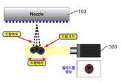
잉크 도롭의 체적 측정을 위한 기술로서 도 1 에 도시된 바와 같이 광학시스템(조명, 렌즈, 카메라)을 이용하여 측정하는 방법이 사용되고 있다. 잉크젯장치(100)에서 분사되는 잉크 도롭에 대해 조광부(200)에 의해 조명하면서 카메라(300)에 의해 촬영한 다음 이미지 데이터를 프레임 그래버(400)를 통해 PC(500)로 전송하여 도롭 영상 이미지를 확보하게 된다.As a technique for measuring the volume of the ink drop, a method of measuring by using an optical system (light, lens, camera) is used as shown in FIG. 1. The ink droplets ejected from the
그런데, 매우 작은 크기를 가지는 잉크 도롭이 매우 빠른 속도로 분사됨으로 써 선명(sharpness)하면서 명암(contrast)대비가 좋은 싱글 도롭 영상을 획득하기가 어려운 문제점이 존재하고 있다.However, there is a problem that it is difficult to obtain a single drop image having good contrast and sharpness because the ink drop having a very small size is injected at a very high speed.
즉, 빠른 속도의 도롭을 촬영하기 위해서는 노출 시간이 아주 짧아야 하며 이로 인해 촬영 이미지가 전체적으로 상당히 어두워짐으로써 배경과 도롭과의 명암대비가 현저히 낮아진다.In other words, in order to shoot a high speed doro, the exposure time should be very short, which causes the overall image to be considerably darker, which significantly lowers the contrast between the background and the doro.
또한, 미세 도롭체적은 렌즈의 배율을 높혀야만 보이게 되고, 높은 렌즈의 배율과 짧은 노출시간은 싱글 도롭영상에서 블러링(Blurring)을 초래한다. 블러링은 빠르게 이동하는 물체를 카메라를 이용하여 촬영하였을 때 발생하는 끌림현상으로 원래의 크기를 추정하는데 악영향을 미친다.In addition, the fine rob volume is visible only when the magnification of the lens is increased, and the high magnification and the short exposure time cause blurring in the single rob image. Blurring is a drag phenomenon that occurs when a fast moving object is photographed using a camera, and has an adverse effect on estimating the original size.
블러링을 방지하기 위해서는 1μs 이하의 상당히 짧은 노출시간이 필요하다. 하지만 카메라의 노출시간과 영상의 명암비는 반비례하므로 블러링을 없애기 위해 노출시간을 짧게 설정할 경우, 영상은 매우 어두워져서 측정 대상체를 확인할 수 없게 된다.To prevent blurring, a fairly short exposure time of less than 1μs is required. However, since the exposure time of the camera and the contrast ratio of the image are inversely proportional, if the exposure time is set to shorten the blurring, the image becomes very dark and the object to be measured cannot be identified.
이러한 문제를 해결하기 위해 도 2 에 도시된 바와 같이 멀티 도롭 영상을 이용한 잉크 도롭 체적 측정방법이 공지되어 있다.In order to solve this problem, an ink drop volume measurement method using a multi drop image is known as shown in FIG. 2.
이 방법에서는 카메라의 노출 시간을 짧게 유지한 채, 수십 번의 잉크 도롭을 떨어뜨리고 떨어지는 도롭 영상을 촬상한다. 이렇게 얻어진 수십 장의 싱글 도롭 영상을 중첩시켜 명암비가 증가된 하나의 멀티도롭 영상으로 가공하고 가공된 영상을 가지고 수치 해석적 방법에 의해 도롭체적을 측정한다.This method captures a drop-drop image by dropping dozens of ink drops while keeping the exposure time of the camera short. The dozens of single dop images obtained in this manner are superimposed into one multi-rop image with increased contrast ratio, and the processed image is measured by numerical analysis method.
이와 같이 멀티 도롭을 통해 얻어진 중첩영상은 싱글 도롭 영상에 비해 상당 히 개선된 명암비를 보여주나, 멀티 드롭에 의해 중첩된 영상이 정확한 영상을 재현하기 위해서는 잉크젯 헤드의 노즐에서 분사되는 도롭이 항상 동일한 크기, 속도 그리고 분사방향을 가질 것이 전제가 되어야 한다.The superimposed images obtained through the multi-ropes show a significantly improved contrast ratio compared to the single-rop images.However, in order to reproduce an accurate image of the superimposed images by the multi-drop, the ejected jets from the nozzle of the inkjet head are always the same size. It must be assumed to have speed, direction of injection and direction of injection.
그러나, 현실적으로는 도롭의 크기와 속도, 방향은 노즐과 잉크의 특성과 잉크젯 헤드에 인가되는 전압레벨 등의 미세한 차이로 인해 분사될 때마다 그 특성이 조금씩 달라지게 됨으로써, 이로 인한 중첩 노이즈를 포함되어 수십장의 싱글도롭 영상을 중첩시켜 멀티도롭 영상을 만들어도 선명도와 명암비가 떨어지는 단점이 존재하고 있다.However, in reality, the size, speed, and direction of the robes vary slightly every time they are injected due to minute differences in the characteristics of the nozzles and the ink and the voltage level applied to the inkjet head, thereby including overlapping noise. Even if you create a multi-rope image by overlapping dozens of single-rope images, there is a disadvantage in that the sharpness and contrast ratio fall.
또한, 멀티도롭에 의해 생성된 중첩 노이즈는 해석(분석)할 수 없기 때문에 멀티도롭을 이용한 도롭체적의 측정은 환경적으로 발생되는 도롭의 변화를 평균적인 해석 관점에서 접근하여 이미지를 재해석하여 사용한다. 이는 도롭의 변화가 작으면 효율적인 측정결과를 얻을 수 있지만, 변화가 증가되면 측정결과는 신뢰할 수 없어지는 취약점이 나타난다.In addition, since the overlap noise generated by the multidrop can not be analyzed (analyzed), the measurement of the drop volume using the multidrop can reinterpret the image by approaching the environmentally generated change of the drop from the average analysis point of view. Use it. This means that if the change in the rob is small, efficient measurement results can be obtained, but if the change is increased, the measurement result becomes unreliable.
기존의 멀티도롭을 이용한 도롭체적 측정은 명암비와 선명도를 향상시키는 관점에서 접근하였다. 하지만 측정 데이터에 오차를 발생시키는 환경변수를 측정 시스템에 반영하지 못하였다.Conventional volume measurement using multi-drop is approached from the viewpoint of improving contrast ratio and sharpness. However, the environmental variables causing errors in the measurement data could not be reflected in the measurement system.
결국, 잉크젯 장비에서 비전(카메라)을 이용한 도롭체적 측정 장치는 신뢰할 수 없는 측정 데이터로 인해 사용상의 한계를 가지게 되었고 그 대안으로 레이저를 이용한 3D측정 방식을 사용하였다.Eventually, the injector volume measuring device using a vision (camera) in inkjet equipment has a limitation in use due to unreliable measurement data, and alternatively, a 3D measuring method using a laser is used.
이 방식은 플레이크에 떨어 뜨려 형성된 잉크 도롭을 레이저를 통해 스캔하 여 얻어진 3차원 데이터를 분석하여 측정한다. 측정 데이터는 신뢰성이 높은 결과를 가져오지만, 시스템 구축을 위한 비용이 크고, 비전 측정 방식에 비해 긴 측정 시간과 정확한 측정을 위한 플레이트면의 관리 등으로 인해 공장 자동화 장비로서 큰 부담이 되고 있다.This method analyzes and measures the three-dimensional data obtained by scanning the ink drop formed by dropping the flakes with a laser. Although measurement data results in high reliability, it is expensive as a factory automation equipment due to the high cost for system construction and the long measurement time and plate management for accurate measurement compared to the vision measurement method.
본 발명은 전술한 문제점을 해결하기 위한 것으로서, 잉크 도롭 체적을 좀 더 간단하면서 경제적으로 동시에 더욱 정확하게 측정할 수 있는 잉크 도롭 체적 측정장치 및 방법을 제공하는 것을 기술적 과제로 한다.SUMMARY OF THE INVENTION The present invention has been made in view of the above problems, and an object of the present invention is to provide an ink drop volume measuring apparatus and method capable of measuring ink drop volume more accurately and at the same time more accurately.
본 발명은 전술한 과제를 해결하기 위해, 잉크젯장치의 노즐에서 분사된 잉크 도롭의 체적을 측정하기 위한 장치로서, 잉크 도롭에 조명을 조사하는 조광부와, 분사된 조사된 잉크 도롭을 촬영하기 위해 잉크 도롭의 하락방향으로 거리(D)를 두고 이격되어 설치되어 특정 분해능(R)을 가지며 시간차(T)를 두고 촬영되는 복수의 카메라와, 상기 카메라에 의해 촬영된 아날로그 영상 이미지 신호를 디지털 신호로 변환하기 위한 프레임 그래버와, 상기 프레임 그래버와 연결되어 잉크 도롭의 체적을 연산하기 위한 체적 산출부를 포함하여 이루어지며, 상기 체적 산출부는, 상기 각 카메라로부터 촬영된 잉크 드롭 영상의 외형곡선을 커브피팅을 통해 수학식으로 모델링하고 이 수학식으로부터 잉크 드롭의 장축길이(b1)를 연산하는 잉 크 드롭 장축길이(b1) 연산부와, 상기 카메라에서 촬영된 잉크 드롭 영상으로부터 다음의 식에 의해 블러링 길이(b2)를 산출하는 블러링 길이(b2) 산출부와, b2 = (V × E)/ R, V (잉크 도롭의 속도) = D / T, 여기서 D 는 각각의 카메라에 찍힌 잉크 도롭사이의 거리. 상기 잉크 드롭 장축길이(b1)에서 산출부, 블러링 길이(b2)를 감한 나머지를 장축길이(b)로 하여 잉크 드롭의 외형곡선을 커브 피팅하여 수학식으로 모델링하고 이 수학식에서 장축을 중심으로 하여 적분함으로써 잉크 드롭의 체적을 연산하는 체적연산부로 이루어지는 것을 특징으로 한다.SUMMARY OF THE INVENTION In order to solve the above problems, the present invention provides a device for measuring the volume of an ink drop dropped from a nozzle of an ink jet apparatus, comprising: a lighting unit for illuminating the ink drop and an image of the injected ink drop. A plurality of cameras spaced apart at a distance D in the direction of the ink drop and having a specific resolution R and photographed with a time difference T, and an analog image image signal captured by the camera as a digital signal. A frame grabber for conversion and a volume calculator configured to calculate a volume of the ink drop in connection with the frame grabber, wherein the volume calculator is configured to perform curve fitting on an outline curve of the ink drop image photographed by the cameras. ink drop major axis length (b1) for computing the major axis length (b1) of the ink drop from the equation and the equation model with Computing section and, with the camera blurring length (b2) for calculating a blur length (b2) by the following equation from the recorded ink drop images from calculatingunit, b 2 = (V × E ) / R, V (Speed of ink drop) = D / T, where D is the distance between ink drop taken by each camera. Using the ink drop long axis length (b1 ) subtracting the calculating unit, the blurring length (b2 ) as the long axis length (b), the contour of the ink drop is curve-fitted and modeled by the equation, and the long axis in this equation And a volume calculating section for calculating the volume of the ink drop by integrating at the center.
본 발명의 잉크 도롭 체적 측정장치에서, 상기 체적 산출부는 상기 조광부에 의한 셰이딩 및 노이즈를 처리하기 위한 배경 균일화부 및 촬영된 잉크 도롭의 외곽선을 특정하기 위한 외곽선 처리부의 어느 일방이나 양방을 추가로 구비하는 것을 특징으로 한다.In the ink drop volume measuring apparatus of the present invention, the volume calculator further includes either or both of a background equalizer for processing shading and noise by the dimming unit and an outline processing unit for specifying the outline of the photographed ink drop. It is characterized by including.
본 발명의 잉크 도롭 체적 측정장치에서, 상기 복수 개의 카메라는 상면에서 볼 때 서로 각도(θ)가 형성되도록 배치되는 것을 특징으로 한다.In the ink drop volume measuring apparatus of the present invention, the plurality of cameras are arranged such that angles θ are formed to each other when viewed from an upper surface.
본 발명의 잉크 드롭 체적 측정방법은 잉크젯장치의 노즐에서 분사된 잉크 도롭의 체적을 측정하기 위한 방법으로서, 잉크젯에서 분사된 노즐의 진행방향으로 거리를 두고 이격되어 설치되며 특정 분해능(R)을 가지는 카메라를 특정 노출시간(E)으로 특정 시간차(T)를 두고 각각 잉크 드롭을 촬영하는 단계(S10); 촬영된 잉크 드롭의 장변길이(b1)를 연산하는 단계(S20); 촬영된 잉크 드롭에서의 장변방향 블러링 길이(b2)를 연산하는 단계(S30); 및 단계(S20)에서 연산된 잉크 드롭의 장변길이(b1)에서 단계(S30)에서 연산된 잉크 드롭의 장변방향 블러링 길이(b2)를 감한 나머지를 잉크 드롭의 장변길이(b)로 하여 잉크 드롭의 체적을 연산하는 단계(S40)를 포함하여 이루어지는 것을 특징으로 한다.The ink drop volume measuring method of the present invention is a method for measuring the volume of ink drop ejected from a nozzle of an ink jet apparatus, and is spaced apart at a distance in the direction of travel of the nozzle ejected from the ink jet and has a specific resolution (R). Photographing ink drops with a specific time difference T at a specific exposure time E of the camera (S10); Calculating a long side length b1 of the photographed ink drop (S20); Calculating a long side blurring length b2 in the photographed ink drop (S30); And subtracting the long side direction blurring length b2 of the ink drop calculated in step S30 from the long side length b1 of the ink drop calculated in step S20 to the long side length b of the ink drop. And calculating a volume of the ink drop (S40).
본 발명의 잉크 도롭 체적 측정방법에서, 상기 단계(S10)는, 촬영된 영상 이미지의 배경에서의 셰이딩 및 노이즈를 제거하기 위한 배경 균일화 단계(S11)와, 잉크젯에서 분사된 노즐의 진행방향으로 거리를 두고 이격되어 설치되며 특정 분해능(R)을 가지는 카메라를 특정 노출시간(E)으로 특정 시간차(T)를 두고 각각 잉크 드롭을 촬영하고 각 카메라에서의 잉크 도롭사이의 거리(D)를 측정하는 단계(S12)로 이루어지는 것을 특징으로 한다.In the ink drop volume measuring method of the present invention, the step (S10), the background uniformity step (S11) for removing the shading and noise in the background of the photographed video image, and the distance in the advancing direction of the nozzle ejected from the inkjet The cameras are spaced apart from each other and have a specific resolution (R), and each ink drop is shot at a specific exposure time (E) at a specific exposure time (E), and the distance (D) between ink drops is measured from each camera. Characterized in that step S12.
본 발명의 잉크 도롭 체적 측정방법에서, 상기 단계(S20)는, 카메라에서 촬영된 영상에서 잉크 도롭의 외형곡선을 특정하는 단계(S21), 특정된 잉크 도롭의 외형곡선을 커브 피팅을 통해 수학식으로 모델링하는 단계(S22), 및 이 수학식을 이용하여 잉크 드롭의 장변길이(b1)를 연산하는 단계(S23)로 이루어지는 것을 특징으로 한다.In the ink drop volume measuring method of the present invention, the step (S20), the step of specifying the outline curve of the ink drop in the image taken by the camera (S21), the outline of the specified ink drop is through the equation fitting curve It is characterized in that it comprises the step (S22) of modeling, and the step (S23) of calculating the long side length (b1 ) of the ink drop using this equation.
본 발명의 잉크 도롭 체적 측정방법에서, 상기 단계(S30)에서 블러링 길이(b2)는 다음의 식에 의해 결정되는 것을 특징으로 한다.In the ink drop volume measurement method of the present invention, the blurring length b2 in the step S30 is characterized by the following equation.
b2 = (V × E)/ R,b2 = (V × E) / R,
V (잉크 도롭의 속도) = D / T, 여기서 D 는 각각의 카메라에 찍힌 잉크 도롭사이의 거리.V (speed of ink drop) = D / T, where D is the distance between ink drops taken on each camera.
본 발명의 잉크 도롭 체적 측정방법에서, 상기 단계(20) 또는 단계(S40)에서 잉크 도롭에 대한 수학적 모델링은 타원방정식으로 하는 것을 특징으로 한다.In the ink drop volume measuring method of the present invention, the mathematical modeling of the ink drop in the
본 발명의 잉크 도롭 체적 측정방법에서, 상기 단계(20) 또는 단계(S40)에서 잉크 도롭에 대한 수학적 모델링은 다차원 방정식으로 하는 것을 특징으로 한다.In the ink drop volume measuring method of the present invention, the mathematical modeling of the ink drop in the
본 발명의 잉크 도롭 체적 측정방법에서, 상기 잉크 드롭 체적 연산 단계(S40)는 타원 또는 다차원방정식을 잉크 드롭의 낙하방향을 중심으로 하여 회전적분시킴으로써 연산되는 것을 특징으로 한다.In the ink drop volume measuring method of the present invention, the ink drop volume calculating step (S40) is characterized by calculating by integrating an ellipse or a multi-dimensional equation around the drop direction of the ink drop.
본 발명은 전술한 구성 및 방법에 의해 두대의 카메라를 이용하여 잉크 드롭을 촬영하고 블러링에 의한 편차를 보정하여 환경변수를 반영할 수 있는 시스템을 구축함으로써 영상 분석과 수치해석을 통해 정확한 도롭체적을 가능하게 되는 효과를 가진다.According to the above-described configuration and method, an ink drop is photographed using two cameras, and a system capable of reflecting environmental variables by correcting deviations due to blurring can be constructed to accurately calculate volume through image analysis and numerical analysis. Has the effect of being possible.
또한, 이와 같은 정확한 잉크 드롭 측정효과가 단순히 2개의 카메라에 의한 방식만으로 달성되는 바, 종래의 레이저 비전 시스템에서와 같이 고가의 번잡한 장비없이 경제적이면서 간단하게 잉크 드롭의 측정이 가능하게 된다.In addition, such an accurate ink drop measurement effect is achieved only by the method of two cameras, it is possible to measure the ink drop economically and simply without expensive complicated equipment as in the conventional laser vision system.
이하, 도면을 참조하여 본 발명의 잉크 도롭의 체적 측정 장치의 일 실시예에 대해 설명한다. 도 3 은 본 발명의 잉크 도롭 체적측정장치를 도시하는 도면 이다.EMBODIMENT OF THE INVENTION Hereinafter, one Example of the volume measuring apparatus of the ink drop of this invention is described with reference to drawings. 3 is a view showing the ink drop volume measurement apparatus of the present invention.
본 발명의 잉크 도롭 체적 측정장치는, 잉크젯(10)으로부터 분사되는 잉크 도롭의 하락방향에 수직하게 조명을 조사하는 조광부(20)와, 상기 조광부에 의해 조사된 잉크 도롭을 촬영하기 위한 카메라(31,32)와, 상기 복수의 카메라(31,32)에 의해 촬영된 영상 이미지 데이터를 받아 잉크 도롭의 체적을 계산하기 위한 프레임 그래버(40)와, 상기 프레임 그래버(40)에 연결되는 체적 산출부(50)를 포함하는 PC(90)로 이루어진다.The ink drop volume measuring apparatus of the present invention includes a
조광부(20)는 통상적으로 LED 조명으로 이루어진다.The
복수 개의 카메라(31,32)는 잉크 도롭의 하락방향의 상하로 거리를 두고 이격되어 설치되며 특정 분해능(R)을 가지며 시간차(T)를 두고 촬영되도록 구성된다.The plurality of
카메라(31,32)사이의 상하방향거리와 카메라 사이의 촬영 시간차(T)는 잉크젯의 통상적인 분사속도를 고려하여 이에 대응하도록 선정함으로써 각 잉크 도롭이 각 카메라의 촬영범위 내에 포함되어 촬영되게 한다.The shooting distance difference T between the
한편, 복수 개의 카메라는 잉크 도롭 방향의 상하로 서로 특정거리만큼 이격되어 구성될 뿐 아니라 서로 소정의 각도(θ)를 이루도록 배치되어 여러 각도에서의 잉크 드롭체적을 측정하는 것도 가능하다.On the other hand, the plurality of cameras are not only configured to be spaced apart from each other by a specific distance up and down in the ink drop direction, but also arranged to form a predetermined angle (θ) with each other, it is also possible to measure the ink drop volume at various angles.
프레임 그래버(40)는, 카메라(31,32)와 같은 영상 매체를 통해 나타나는 아날로그 영상 신호를 샘플당 정의된 비트로 디지털화하여 개인용 PC(50)가 처리할 수 있는 신호로 바꾸어 주는 작용을 한다.The frame grabber 40 digitizes an analog video signal appearing through video media such as
체적 산출부(50)는 사용자의 사용이 용이한 PC(50) 또는 별개로 구성되는 제 어실(미도시)에 포함되도록 구성될 수 있다.The
체적 산출부(50)는 잉크 드롭 장축길이(b1) 연산부(60)와, 블러링 길이(b2) 산출부(70)와, 체적 연산부(80)로 이루어진다.The
잉크 드롭 장축길이(b1) 연산부는 각 카메라로부터 촬영된 잉크 드롭 영상의 외형곡선을 커브피팅을 통해 수학식으로 모델링하고 이 수학식으로부터 잉크 드롭의 장축길이(b1)를 연산하는 작용을 한다.The ink drop major axis length (b1 ) calculating unit functions to model the outline curve of the ink drop image photographed by each camera through curve fitting, and calculate the long axis length (b1 ) of the ink drop from the equation. .
블러링 길이(b2) 산출부는 카메라(31,32)에서 촬영된 잉크 드롭 영상으로부터 다음의 식에 의해 블러링 길이(b2)를 산출하는 작용을 한다.The blurring length b2 calculating unit functions to calculate the blurring length b2 from the ink drop images photographed by the
b2 = (V × E)/ R, V (잉크 도롭의 속도) = D / T, 여기서 D 는 각각의 카메라에 찍힌 잉크 도롭사이의 거리.b2 = (V × E) / R, V (speed of ink drop) = D / T, where D is the distance between ink drops taken on each camera.
체적연산부(80)는 상기 잉크 드롭 장축길이(b1)에서 산출부, 블러링 길이(b2)를 감한 나머지를 장축길이(b)로 하여 잉크 드롭의 외형곡선을 커브 피팅하여 수학식으로 산출하고 이 수학식을 장축을 중심으로 하여 적분함으로써 잉크 드롭의 체적을 연산하는 작용을 한다.The
다음으로 이와 같이 형성된 잉크 도롭 체적 측정장치를 이용하여 잉크 도롭 체적을 측정하는 방법에 대해 설명한다. 도 4 는 본 발명의 잉크 드롭 체적 측정방법 전체를 도시하는 흐름도이다.Next, a method of measuring the ink drop volume by using the ink drop volume measuring device thus formed will be described. Fig. 4 is a flowchart showing the entire ink drop volume measuring method of the present invention.
도 5 는 본 발명의 잉크 드롭 체적 측정방법에서 단계(S10)를 도시하는 흐름도이다.Fig. 5 is a flowchart showing step S10 in the ink drop volume measuring method of the present invention.
먼저, 본 발명의 잉크젯장치의 노즐에서 분사된 잉크 도롭의 체적을 측정하기 위한 방법은 각각의 카메라(31,32)에서 잉크 드롭을 촬영하는 단계(S10)를 수행한다.First, the method for measuring the volume of the ink drop from the nozzle of the inkjet apparatus of the present invention performs the step (S10) of photographing the ink drop in each camera (31,32).
도 6 은 본 발명에서 잉크 드롭 체적 측정방법의 단계(S10)에서 영상 이미지 배경 균일화 단계(S11)를 도시하는 도면이다.FIG. 6 is a diagram showing an image image background uniforming step S11 in step S10 of the method for measuring ink drop volume in the present invention.
단계(S10)에서는 먼저 영상 이미지의 배경에서의 셰이딩 및 노이즈를 제거하기 위해 FFC(Flat Field Correction) 알고리즘을 이용하는 전처리단계(S11)를 수행함으로써 영상 이미지에서 배경을 균일한 영상으로 처리하여 배경과 잉크 도롭과의 대비를 더욱 명확하게 할 수 있게 된다.In step S10, first, the background is processed into a uniform image by performing a preprocessing step (S11) using a flat field correction algorithm (FFC) to remove shading and noise in the background of the image. The contrast with the robes will be clearer.
도 7 은 본 발명에서 잉크 드롭 체적 측정방법의 단계(S10)에서 잉크 드롭 촬연단계(S12)를 도시하는 도면이다.7 is a diagram showing an ink drop photographing step S12 in step S10 of the method for measuring ink drop volume in the present invention.
각각의 카메라(31,32)는 특정 분해능(R)을 가지며 잉크젯장치(10)에서 분사된 노즐의 진행방향으로 거리를 두고 이격되도록 설치되어 특정 노출시간(E)으로 특정 시간차(T)를 두고 각각 잉크 드롭을 촬영하는 단계(S12)를 수행한다.Each of the
본 실시예에서 카메라(31,32)는 1μm/pixel 의 분해능(R)을 가지며 서로 간의 이격거리(D)는 30μm 로 설정하고 노출시간(E)는 1μsec 로 설정하였다.In this embodiment, the
이와 같이 촬영됨으로써 제1카메라(31)에서의 잉크 도롭과 제2카메라(32)에서의 잉크 도롭 사이의 거리(D)가 측정될 수 있다.In this way, the distance D between the ink drop in the
도 8 은 본 발명의 잉크 드롭 체적 측정방법에서 단계(S20)를 도시하는 흐름도이다.8 is a flowchart showing step S20 in the ink drop volume measuring method of the present invention.
다음으로, 카메라(31,32)에서 촬영된 잉크 드롭의 장변길이(b1)를 연산하는 단계(S20)를 수행한다.Next, a step S20 of calculating the long side length b1 of the ink drops photographed by the
촬영된 잉크 도롭의 장변길이(b1)는 잉크 도롭이 명확하게 촬영된 경우에는 이를 그대로 이용하여 장변길이를 측정할 수도 있다.When the ink drop is clearly photographed, the long side length b1 of the photographed ink drop may be used to measure the long side length.
그러나, 전술한 바와 같이 잉크 도롭의 형상이 블러링되어 불명확한 경우가 더 일반적인 경우에 해당되는 바, 다음과 같은 단계에 의해 산출되는 것이 바람직하다.However, as described above, the case where the shape of the ink drop is blurred due to blurring is more general. Therefore, it is preferable that the ink drop is calculated by the following steps.
도 9 는 본 발명에서 잉크 드롭 체적 측정방법의 단계(S21)에서 촬영된 잉크 드롭 외형곡선 특정 단계(S21)를 도시하는 도면이다.FIG. 9 is a diagram showing an ink drop outline curve specifying step S21 taken in step S21 of the method for measuring ink drop volume in the present invention.
단계(S10)에서 촬영된 영상 이미지에서는 도롭의 형상에 있어서 선명도와 명암도가 낮아 정확한 형상을 특정하기 어렵고 장변길이를 측정하기 어려운 경우가 발생하므로 에지 디텍션(Edge Detection) 알고리즘 등을 이용하는 잉크 도롭의 외형곡선을 특정하는 단계(S21)를 수행한다.In the image image photographed at step S10, the sharpness and contrast of the shape of the dop are low, making it difficult to specify an accurate shape and measuring the long side length. Therefore, the shape of the ink drop using the edge detection algorithm or the like Step S21 of specifying the curve is performed.
도 10 은 본 발명에서 잉크 드롭 체적 측정방법의 단계(S22)에서 특정된 잉크 드롭 외형곡선을 수학적 모델링하는 단계(S22)를 도시하는 도면이다.FIG. 10 is a diagram showing a step S22 of mathematically modeling an ink drop contour curve specified in step S22 of the method for measuring ink drop volume in the present invention.
그런 다음, 단계(S21)에서 특정된 잉크 도롭의 외형곡선을 커브 피팅을 통해 수학식으로 모델링하는 단계(S22)를 수행한다.Then, a step S22 of modeling the outline curve of the ink dorop specified in the step S21 through curve fitting is performed.
본 실시예에서는 잉크 드롭의 외형곡선에 대한 수학식으로 타원방정식을 이용하여 x2/a2 + y2/b12 = 1 로 모델링하였다.In this embodiment, the equation for the contour of the ink drop was modeled as x2 / a2 + y2 / b12 = 1 using an elliptic equation.
이러한 수학식으로 모델링하는 방법으로 리스트 스퀘어 피팅(Least Square Fitting)방법을 사용하였다.The Least Square Fitting method was used as a modeling method.
잉크 드롭의 외형곡선에 대해 본 실시예에서는 전체를 하나의 타원방정식으고 모델링하였으나 이에 한정되는 것은 아니며, 예를 들어 잉크 드롭의 좌측 내지 우측면에 대해 4차 방정식과 같은 고차 방정식을 이용하여 모델링하는 것도 가능하다.The outline of the ink drop is modeled as an elliptic equation in the present embodiment, but the present invention is not limited thereto. For example, modeling the left or right side of the ink drop using a higher-order equation, such as a fourth-order equation, is also possible. It is possible.
이러한 수학적 모델링에 의해 잉크 드롭의 장축 길이(b1)를 수학적인 연산에 의해 결정하는 단계(S23)를 수행하게 된다.By such mathematical modeling, the step S23 of determining the major axis length b1 of the ink drop by mathematical calculation is performed.
본 실시예에서는 수학적인 연산결과 a = 15㎛, b1 = 17㎛ 로 결정되었다.In the present embodiment, the mathematical operation result is determined to be a = 15 μm and b1 = 17 μm.
그런 다음으로는, 블러링 길이(b2)를 연산하는 단계(S30)를 수행하게 된다.Next, the step S30 of calculating the blurring length b2 is performed.
블러링 길이(b2)는 다음의 식에 의해 결정된다.The blurring length b2 is determined by the following equation.
b2 = (V × E)/ R = (30μm/6sec ×1μsec)/(1μm/pixel) = 5 pixelb2 = (V × E) / R = (30μm / 6sec × 1μsec) / (1μm / pixel) = 5 pixel
(V : 잉크 도롭의 속도 = D / T, D : 각각의 카메라에 찍힌 잉크 도롭사이의 거리.)(V: speed of ink drop = D / T, D: distance between ink drop on each camera.)
도 11 은 본 발명의 잉크 드롭 체적 측정방법에서 단계(S40)를 도시하는 도면이다.11 is a diagram showing step S40 in the method for measuring ink drop volume of the present invention.
마지막으로, 촬영된 잉크 드롭의 장변길이(b1)에서 블러링 길이(b2)를 뺀 나머지를 장변길이(b = b1 - b2)로 하여 잉크 드롭의 체적을 연산하는 단계(S40)를 수행한다.Finally, calculating the volume of the ink drop by subtracting the blurring length (b2 ) from the long side length (b1 ) of the photographed ink drop as the long side length (b = b1 -b2 ) (S40). Perform
b = 37μm - 5μm = 32 μm/2 = 16 μmb = 37 μm-5 μm = 32 μm / 2 = 16 μm
잉크 드롭의 체적을 계산하기 위해, 이 잉크드롭의 체적을 타원이 y 축을 중심으로 회전한 타원체로 상정하고 이러한 타원체에 대해 수학적으로 체적을 계산하면,To calculate the volume of the ink drop, assume that the volume of this ink drop is an ellipsoid with an ellipse rotated about the y axis and mathematically calculate the volume for these ellipsoids.
타원방정식 x2/a2 + y2/b2 = 1(1)Elliptic equation x2 / a2 + y2 / b2 = 1 (1)
V = 2π∫x2 dy 에서 x2 를 식(1)을 이용하여 y의 항으로 대체하여 적분하여 y 값으로 b 를 대입하여 정리하면 다음과 같이 된다.In V = 2π∫x2 dy, x2 is replaced by the term of y using Equation (1), integrated, and b is substituted for y.
V = 4πa2b/3V = 4πa2 b / 3
여기에, 본 실시예에서 연산된 a = 15㎛, b = 16㎛ 를 대입하여 계산하면 잉크 드롭의 체적은 15. 072 pL 가 된다.Here, the volume of the ink drop is 15,072 pL, by substituting a = 15 μm and b = 16 μm calculated in the present embodiment.
이와 같이 본 발명은 2개의 카메라를 이용함으로써 블러링과 같은 환경변수를 고려한 영상분석과 수치해석을 통해 정확한 드롭의 체적을 산출하는 작용을 하 게 된다.As described above, the present invention uses two cameras to calculate an accurate drop volume through image analysis and numerical analysis considering environmental variables such as blurring.
전술한 실시예는 본 발명의 기술적 사상을 예시적으로 기술한 것인 바, 본 발명을 제한하는 것으로 해석될 수 없는 것이며, 따라서 본 발명의 기술적 범위를 벗어나지 않는 한도 내에서 변형 및 수정 가능한 것으로 해석되어야 한다.The foregoing embodiments are illustrative of the technical spirit of the present invention, and thus are not to be construed as limiting the present invention, and thus, may be modified and modified without departing from the technical scope of the present invention. Should be.
도 1 은 종래기술에서 잉크젯 분사노즐에서 분사된 잉크 도롭을 측정 장치를 도시하는 도면이다.BRIEF DESCRIPTION OF THE DRAWINGS Fig. 1 is a view showing a device for measuring ink drops ejected from an inkjet jet nozzle in the prior art.
도 2 는 도 2 의 측정장치를 통해 잉크 노즐의 체적을 측정하는 방법을 도시하는 도면이다.FIG. 2 is a diagram illustrating a method of measuring the volume of an ink nozzle through the measuring device of FIG. 2.
도 3 은 본 발명의 잉크 도롭 체적측정장치를 도시하는 도면이다.3 is a view showing the ink drop volume measurement apparatus of the present invention.
도 4 는 본 발명의 잉크 드롭 체적 측정방법 전체를 도시하는 흐름도이다.Fig. 4 is a flowchart showing the entire ink drop volume measuring method of the present invention.
도 5 는 본 발명의 잉크 드롭 체적 측정방법에서 단계(S10)를 도시하는 흐름도이다.Fig. 5 is a flowchart showing step S10 in the ink drop volume measuring method of the present invention.
도 6 은 본 발명에서 잉크 드롭 체적 측정방법의 단계(S10)에서 영상 이미지 배경 균일화 단계(S11)를 도시하는 도면이다.FIG. 6 is a diagram showing an image image background uniforming step S11 in step S10 of the method for measuring ink drop volume in the present invention.
도 7 은 본 발명에서 잉크 드롭 체적 측정방법의 단계(S10)에서 잉크 드롭 촬연단계(S12)를 도시하는 도면이다.7 is a diagram showing an ink drop photographing step S12 in step S10 of the method for measuring ink drop volume in the present invention.
도 8 은 본 발명의 잉크 드롭 체적 측정방법에서 단계(S20)를 도시하는 흐름도이다.8 is a flowchart showing step S20 in the ink drop volume measuring method of the present invention.
도 9 는 본 발명에서 잉크 드롭 체적 측정방법의 단계(S21)에서 촬영된 잉크 드롭 외형곡선 특정 단계(S21)를 도시하는 도면이다.FIG. 9 is a diagram showing an ink drop outline curve specifying step S21 taken in step S21 of the method for measuring ink drop volume in the present invention.
도 10 은 본 발명에서 잉크 드롭 체적 측정방법의 단계(S22)에서 특정된 잉크 드롭 외형곡선을 수학적 모델링하는 단계(S22)를 도시하는 도면이다.FIG. 10 is a diagram showing a step S22 of mathematically modeling an ink drop contour curve specified in step S22 of the method for measuring ink drop volume in the present invention.
도 11 은 본 발명의 잉크 드롭 체적 측정방법에서 단계(S40)를 도시하는 도 면이다.Fig. 11 is a diagram showing step S40 in the method for measuring ink drop volume of the present invention.
Claims (10)
Translated fromKoreanPriority Applications (1)
| Application Number | Priority Date | Filing Date | Title |
|---|---|---|---|
| KR1020080097258AKR100997451B1 (en) | 2008-10-02 | 2008-10-02 | Ink drop volume measuring device and method |
Applications Claiming Priority (1)
| Application Number | Priority Date | Filing Date | Title |
|---|---|---|---|
| KR1020080097258AKR100997451B1 (en) | 2008-10-02 | 2008-10-02 | Ink drop volume measuring device and method |
Publications (2)
| Publication Number | Publication Date |
|---|---|
| KR20100037914Atrue KR20100037914A (en) | 2010-04-12 |
| KR100997451B1 KR100997451B1 (en) | 2010-12-07 |
Family
ID=42214961
Family Applications (1)
| Application Number | Title | Priority Date | Filing Date |
|---|---|---|---|
| KR1020080097258AActiveKR100997451B1 (en) | 2008-10-02 | 2008-10-02 | Ink drop volume measuring device and method |
Country Status (1)
| Country | Link |
|---|---|
| KR (1) | KR100997451B1 (en) |
Cited By (27)
| Publication number | Priority date | Publication date | Assignee | Title |
|---|---|---|---|---|
| US20120013735A1 (en)* | 2010-07-15 | 2012-01-19 | Kai Tao | IV monitoring by video and image processing |
| US9372486B2 (en) | 2011-12-21 | 2016-06-21 | Deka Products Limited Partnership | System, method, and apparatus for monitoring, regulating, or controlling fluid flow |
| US9435455B2 (en) | 2011-12-21 | 2016-09-06 | Deka Products Limited Partnership | System, method, and apparatus for monitoring, regulating, or controlling fluid flow |
| CN106004044A (en)* | 2016-05-11 | 2016-10-12 | 京东方科技集团股份有限公司 | Ink measuring system and printing equipment |
| KR20170010080A (en)* | 2011-12-21 | 2017-01-25 | 데카 프로덕츠 리미티드 파트너쉽 | Apparatus for controlling fluid flow |
| US9724467B2 (en) | 2011-12-21 | 2017-08-08 | Deka Products Limited Partnership | Flow meter |
| US9746094B2 (en) | 2011-12-21 | 2017-08-29 | Deka Products Limited Partnership | Flow meter having a background pattern with first and second portions |
| US9746093B2 (en) | 2011-12-21 | 2017-08-29 | Deka Products Limited Partnership | Flow meter and related system and apparatus |
| US9759343B2 (en) | 2012-12-21 | 2017-09-12 | Deka Products Limited Partnership | Flow meter using a dynamic background image |
| USD799025S1 (en) | 2013-11-06 | 2017-10-03 | Deka Products Limited Partnership | Apparatus to control fluid flow through a tube |
| USD802118S1 (en) | 2013-11-06 | 2017-11-07 | Deka Products Limited Partnership | Apparatus to control fluid flow through a tube |
| USD813376S1 (en) | 2013-11-06 | 2018-03-20 | Deka Products Limited Partnership | Apparatus to control fluid flow through a tube |
| USD815730S1 (en) | 2013-11-06 | 2018-04-17 | Deka Products Limited Partnership | Apparatus to control fluid flow through a tube |
| USD816829S1 (en) | 2013-11-06 | 2018-05-01 | Deka Products Limited Partnership | Apparatus to control fluid flow through a tube |
| KR20180060898A (en)* | 2016-11-28 | 2018-06-07 | 세메스 주식회사 | Printing Method by using Inkjet Head Unit |
| CN108340679A (en)* | 2017-01-24 | 2018-07-31 | 京东方科技集团股份有限公司 | The regulating device and adjusting method of droplet size |
| CN108528050A (en)* | 2018-04-14 | 2018-09-14 | 大丰鑫源达化工有限公司 | The system and method for fluency is printed using ink droplet observation instrument tested inks |
| US10088346B2 (en) | 2011-12-21 | 2018-10-02 | Deka Products Limited Partnership | System, method, and apparatus for monitoring, regulating, or controlling fluid flow |
| US10228683B2 (en) | 2011-12-21 | 2019-03-12 | Deka Products Limited Partnership | System, method, and apparatus for monitoring, regulating, or controlling fluid flow |
| USD854145S1 (en) | 2016-05-25 | 2019-07-16 | Deka Products Limited Partnership | Apparatus to control fluid flow through a tube |
| US10488848B2 (en) | 2011-12-21 | 2019-11-26 | Deka Products Limited Partnership | System, method, and apparatus for monitoring, regulating, or controlling fluid flow |
| USD905848S1 (en) | 2016-01-28 | 2020-12-22 | Deka Products Limited Partnership | Apparatus to control fluid flow through a tube |
| CN113686739A (en)* | 2021-08-19 | 2021-11-23 | 杭州电子科技大学 | Method for measuring volume of tiny liquid drop by fitting 8 ellipsoids |
| US11744935B2 (en) | 2016-01-28 | 2023-09-05 | Deka Products Limited Partnership | Apparatus for monitoring, regulating, or controlling fluid flow |
| US11839741B2 (en) | 2019-07-26 | 2023-12-12 | Deka Products Limited Partneship | Apparatus for monitoring, regulating, or controlling fluid flow |
| KR20240027366A (en) | 2022-08-23 | 2024-03-04 | 주식회사 케이씨씨글라스 | Apparatus for testing ink |
| CN119773368A (en)* | 2025-03-10 | 2025-04-08 | 季华实验室 | Ink droplet observation method, device, equipment and computer readable storage medium |
Families Citing this family (2)
| Publication number | Priority date | Publication date | Assignee | Title |
|---|---|---|---|---|
| KR102509680B1 (en) | 2020-12-31 | 2023-03-15 | (주)유니젯 | Ink drop measuring pad, inkjet print device with the pad and its measuring method using thereof |
| KR102608020B1 (en) | 2021-12-30 | 2023-11-30 | (주)유니젯 | Ink drop measuring pad, inkjet print device with the pad and its measuring method using thereof |
Family Cites Families (2)
| Publication number | Priority date | Publication date | Assignee | Title |
|---|---|---|---|---|
| JP4093167B2 (en) | 2003-10-15 | 2008-06-04 | セイコーエプソン株式会社 | Droplet ejection device, electro-optical device manufacturing method, electro-optical device, and electronic apparatus |
| JP4492346B2 (en) | 2004-12-28 | 2010-06-30 | セイコーエプソン株式会社 | Droplet discharge device |
- 2008
- 2008-10-02KRKR1020080097258Apatent/KR100997451B1/enactiveActive
Cited By (57)
| Publication number | Priority date | Publication date | Assignee | Title |
|---|---|---|---|---|
| US20120013735A1 (en)* | 2010-07-15 | 2012-01-19 | Kai Tao | IV monitoring by video and image processing |
| US8531517B2 (en)* | 2010-07-15 | 2013-09-10 | Kai Tao | IV monitoring by video and image processing |
| US11339887B2 (en) | 2011-12-21 | 2022-05-24 | Deka Products Limited Partnership | Flow meter and related method |
| US10894638B2 (en) | 2011-12-21 | 2021-01-19 | Deka Products Limited Partnership | System, method, and apparatus for monitoring, regulating, or controlling fluid flow |
| US12100507B2 (en) | 2011-12-21 | 2024-09-24 | Deka Products Limited Partnership | System, method, and apparatus for monitoring, regulating, or controlling fluid flow |
| KR20170010080A (en)* | 2011-12-21 | 2017-01-25 | 데카 프로덕츠 리미티드 파트너쉽 | Apparatus for controlling fluid flow |
| US9724467B2 (en) | 2011-12-21 | 2017-08-08 | Deka Products Limited Partnership | Flow meter |
| US9724465B2 (en) | 2011-12-21 | 2017-08-08 | Deka Products Limited Partnership | Flow meter |
| US9724466B2 (en) | 2011-12-21 | 2017-08-08 | Deka Products Limited Partnership | Flow meter |
| US9746094B2 (en) | 2011-12-21 | 2017-08-29 | Deka Products Limited Partnership | Flow meter having a background pattern with first and second portions |
| US9746093B2 (en) | 2011-12-21 | 2017-08-29 | Deka Products Limited Partnership | Flow meter and related system and apparatus |
| US10876868B2 (en) | 2011-12-21 | 2020-12-29 | Deka Products Limited Partnership | System, method, and apparatus for monitoring, regulating, or controlling fluid flow |
| US9772044B2 (en) | 2011-12-21 | 2017-09-26 | Deka Products Limited Partnership | Flow metering using a difference image for liquid parameter estimation |
| KR20210014762A (en)* | 2011-12-21 | 2021-02-09 | 데카 프로덕츠 리미티드 파트너쉽 | Apparatus for controlling fluid flow |
| US10844970B2 (en) | 2011-12-21 | 2020-11-24 | Deka Products Limited Partnership | Flow meter |
| US9856990B2 (en) | 2011-12-21 | 2018-01-02 | Deka Products Limited Partnership | Flow metering using a difference image for liquid parameter estimation |
| US10739759B2 (en) | 2011-12-21 | 2020-08-11 | Deka Products Limited Partnership | System, method, and apparatus for monitoring, regulating, or controlling fluid flow |
| US10718445B2 (en) | 2011-12-21 | 2020-07-21 | Deka Products Limited Partnership | Flow meter having a valve |
| US9976665B2 (en) | 2011-12-21 | 2018-05-22 | Deka Products Limited Partnership | Flow meter |
| US9435455B2 (en) | 2011-12-21 | 2016-09-06 | Deka Products Limited Partnership | System, method, and apparatus for monitoring, regulating, or controlling fluid flow |
| US10488848B2 (en) | 2011-12-21 | 2019-11-26 | Deka Products Limited Partnership | System, method, and apparatus for monitoring, regulating, or controlling fluid flow |
| US11738143B2 (en) | 2011-12-21 | 2023-08-29 | Deka Products Limited Partnership | Flow meier having a valve |
| US11574407B2 (en) | 2011-12-21 | 2023-02-07 | Deka Products Limited Partnership | System, method, and apparatus for monitoring, regulating, or controlling fluid flow |
| US11449037B2 (en) | 2011-12-21 | 2022-09-20 | Deka Products Limited Partnership | System, method, and apparatus for monitoring, regulating, or controlling fluid flow |
| US10088346B2 (en) | 2011-12-21 | 2018-10-02 | Deka Products Limited Partnership | System, method, and apparatus for monitoring, regulating, or controlling fluid flow |
| US10113660B2 (en) | 2011-12-21 | 2018-10-30 | Deka Products Limited Partnership | Flow meter |
| US10228683B2 (en) | 2011-12-21 | 2019-03-12 | Deka Products Limited Partnership | System, method, and apparatus for monitoring, regulating, or controlling fluid flow |
| KR20200083650A (en)* | 2011-12-21 | 2020-07-08 | 데카 프로덕츠 리미티드 파트너쉽 | Apparatus for controlling fluid flow |
| US9372486B2 (en) | 2011-12-21 | 2016-06-21 | Deka Products Limited Partnership | System, method, and apparatus for monitoring, regulating, or controlling fluid flow |
| US10436342B2 (en) | 2011-12-21 | 2019-10-08 | Deka Products Limited Partnership | Flow meter and related method |
| US11793928B2 (en) | 2011-12-21 | 2023-10-24 | Deka Products Limited Partnership | Flow meter and related method |
| KR20210112402A (en)* | 2011-12-21 | 2021-09-14 | 데카 프로덕츠 리미티드 파트너쉽 | Apparatus for controlling fluid flow |
| US9759343B2 (en) | 2012-12-21 | 2017-09-12 | Deka Products Limited Partnership | Flow meter using a dynamic background image |
| USD816829S1 (en) | 2013-11-06 | 2018-05-01 | Deka Products Limited Partnership | Apparatus to control fluid flow through a tube |
| USD815730S1 (en) | 2013-11-06 | 2018-04-17 | Deka Products Limited Partnership | Apparatus to control fluid flow through a tube |
| USD813376S1 (en) | 2013-11-06 | 2018-03-20 | Deka Products Limited Partnership | Apparatus to control fluid flow through a tube |
| USD802118S1 (en) | 2013-11-06 | 2017-11-07 | Deka Products Limited Partnership | Apparatus to control fluid flow through a tube |
| USD799025S1 (en) | 2013-11-06 | 2017-10-03 | Deka Products Limited Partnership | Apparatus to control fluid flow through a tube |
| USD943736S1 (en) | 2016-01-28 | 2022-02-15 | Deka Products Limited Partnership | Apparatus to control fluid flow through a tube |
| US11744935B2 (en) | 2016-01-28 | 2023-09-05 | Deka Products Limited Partnership | Apparatus for monitoring, regulating, or controlling fluid flow |
| USD905848S1 (en) | 2016-01-28 | 2020-12-22 | Deka Products Limited Partnership | Apparatus to control fluid flow through a tube |
| CN106004044A (en)* | 2016-05-11 | 2016-10-12 | 京东方科技集团股份有限公司 | Ink measuring system and printing equipment |
| USD1060608S1 (en) | 2016-05-25 | 2025-02-04 | Deka Products Limited Partnership | Device to control fluid flow through a tube |
| USD860437S1 (en) | 2016-05-25 | 2019-09-17 | Deka Products Limited Partnership | Apparatus to control fluid flow through a tube |
| USD854145S1 (en) | 2016-05-25 | 2019-07-16 | Deka Products Limited Partnership | Apparatus to control fluid flow through a tube |
| USD972125S1 (en) | 2016-05-25 | 2022-12-06 | Deka Products Limited Partnership | Apparatus to control fluid flow through a tube |
| USD972718S1 (en) | 2016-05-25 | 2022-12-13 | Deka Products Limited Partnership | Apparatus to control fluid flow through a tube |
| KR20180060898A (en)* | 2016-11-28 | 2018-06-07 | 세메스 주식회사 | Printing Method by using Inkjet Head Unit |
| CN108340679A (en)* | 2017-01-24 | 2018-07-31 | 京东方科技集团股份有限公司 | The regulating device and adjusting method of droplet size |
| WO2018137341A1 (en)* | 2017-01-24 | 2018-08-02 | 京东方科技集团股份有限公司 | Droplet volume detection device and method, and droplet volume adjusting method |
| US10556424B2 (en) | 2017-01-24 | 2020-02-11 | Boe Technology Group Co., Ltd. | Apparatus and method for detecting the volume of a liquid drop, and method for adjusting the volume of a liquid drop |
| CN108528050A (en)* | 2018-04-14 | 2018-09-14 | 大丰鑫源达化工有限公司 | The system and method for fluency is printed using ink droplet observation instrument tested inks |
| US11839741B2 (en) | 2019-07-26 | 2023-12-12 | Deka Products Limited Partneship | Apparatus for monitoring, regulating, or controlling fluid flow |
| CN113686739B (en)* | 2021-08-19 | 2023-10-20 | 杭州电子科技大学 | Method for measuring volume of tiny liquid drop by adopting 8 ellipsoids for fitting |
| CN113686739A (en)* | 2021-08-19 | 2021-11-23 | 杭州电子科技大学 | Method for measuring volume of tiny liquid drop by fitting 8 ellipsoids |
| KR20240027366A (en) | 2022-08-23 | 2024-03-04 | 주식회사 케이씨씨글라스 | Apparatus for testing ink |
| CN119773368A (en)* | 2025-03-10 | 2025-04-08 | 季华实验室 | Ink droplet observation method, device, equipment and computer readable storage medium |
Also Published As
| Publication number | Publication date |
|---|---|
| KR100997451B1 (en) | 2010-12-07 |
Similar Documents
| Publication | Publication Date | Title |
|---|---|---|
| KR100997451B1 (en) | Ink drop volume measuring device and method | |
| US11238613B2 (en) | Dynamical camera calibration | |
| US8967762B2 (en) | Inkjet printer with dot alignment vision system | |
| CN1260544C (en) | Compatible and accurate calibration method for double eye line structure photo-sensor and implementing apparatus | |
| EP1706839B1 (en) | Three-dimensional video scanner | |
| CN101639450A (en) | Printing quality test device | |
| US11360304B2 (en) | Image distortion detection method and system | |
| KR101473091B1 (en) | Apparatus for and method of inspecting substrate | |
| JP2009168582A (en) | Appearance inspecting equipment | |
| JP2010060379A (en) | Contact angle measuring system and contact angle measuring method | |
| HRP20220072T1 (en) | Printing system and method for printing a three-dimensional optical structure, providing real-time quality control of the printed optical structure | |
| CN112361989A (en) | Method for calibrating parameters of measurement system through point cloud uniformity consideration | |
| CN114161713B (en) | Printing head, detection method, storage medium and three-dimensional printer | |
| CN103837545A (en) | Lens imaging device and method | |
| JP6455011B2 (en) | Image processing apparatus, contour extraction method, and program | |
| US11338578B2 (en) | Droplet inspection module and droplet inspection method | |
| CN114707529A (en) | Image quality evaluation method and system in focusing process of linear array camera | |
| KR20140100756A (en) | Measurement Method of Surface Behavior and Sizing Degree for Paper, and Its Measuring Apparatus | |
| KR101095369B1 (en) | How to measure meniscus on ink drops | |
| US20170336918A1 (en) | Touch-sensing devices using minimum depth-value surface characterizations and associated methods | |
| EP3207331B1 (en) | Differential lighting | |
| JP2001201322A (en) | Target of non-contact extensometer and non-contact extensomemter | |
| JP2001322295A (en) | Apparatus for inspecting ink ejection | |
| JP6196148B2 (en) | Defocus control device and defocus control method | |
| CN209250756U (en) | A kind of image capturing system and automated optical detection equipment |
Legal Events
| Date | Code | Title | Description |
|---|---|---|---|
| A201 | Request for examination | ||
| PA0109 | Patent application | St.27 status event code:A-0-1-A10-A12-nap-PA0109 | |
| PA0201 | Request for examination | St.27 status event code:A-1-2-D10-D11-exm-PA0201 | |
| P11-X000 | Amendment of application requested | St.27 status event code:A-2-2-P10-P11-nap-X000 | |
| P13-X000 | Application amended | St.27 status event code:A-2-2-P10-P13-nap-X000 | |
| D13-X000 | Search requested | St.27 status event code:A-1-2-D10-D13-srh-X000 | |
| D14-X000 | Search report completed | St.27 status event code:A-1-2-D10-D14-srh-X000 | |
| PG1501 | Laying open of application | St.27 status event code:A-1-1-Q10-Q12-nap-PG1501 | |
| E902 | Notification of reason for refusal | ||
| PE0902 | Notice of grounds for rejection | St.27 status event code:A-1-2-D10-D21-exm-PE0902 | |
| P11-X000 | Amendment of application requested | St.27 status event code:A-2-2-P10-P11-nap-X000 | |
| P13-X000 | Application amended | St.27 status event code:A-2-2-P10-P13-nap-X000 | |
| E701 | Decision to grant or registration of patent right | ||
| PE0701 | Decision of registration | St.27 status event code:A-1-2-D10-D22-exm-PE0701 | |
| GRNT | Written decision to grant | ||
| PR0701 | Registration of establishment | St.27 status event code:A-2-4-F10-F11-exm-PR0701 | |
| PR1002 | Payment of registration fee | St.27 status event code:A-2-2-U10-U11-oth-PR1002 Fee payment year number:1 | |
| PG1601 | Publication of registration | St.27 status event code:A-4-4-Q10-Q13-nap-PG1601 | |
| FPAY | Annual fee payment | Payment date:20131121 Year of fee payment:4 | |
| PR1001 | Payment of annual fee | St.27 status event code:A-4-4-U10-U11-oth-PR1001 Fee payment year number:4 | |
| FPAY | Annual fee payment | Payment date:20141124 Year of fee payment:5 | |
| PR1001 | Payment of annual fee | St.27 status event code:A-4-4-U10-U11-oth-PR1001 Fee payment year number:5 | |
| FPAY | Annual fee payment | Payment date:20151026 Year of fee payment:6 | |
| PR1001 | Payment of annual fee | St.27 status event code:A-4-4-U10-U11-oth-PR1001 Fee payment year number:6 | |
| P22-X000 | Classification modified | St.27 status event code:A-4-4-P10-P22-nap-X000 | |
| FPAY | Annual fee payment | Payment date:20161123 Year of fee payment:7 | |
| PR1001 | Payment of annual fee | St.27 status event code:A-4-4-U10-U11-oth-PR1001 Fee payment year number:7 | |
| FPAY | Annual fee payment | Payment date:20171123 Year of fee payment:8 | |
| PR1001 | Payment of annual fee | St.27 status event code:A-4-4-U10-U11-oth-PR1001 Fee payment year number:8 | |
| PN2301 | Change of applicant | St.27 status event code:A-5-5-R10-R13-asn-PN2301 St.27 status event code:A-5-5-R10-R11-asn-PN2301 | |
| R18-X000 | Changes to party contact information recorded | St.27 status event code:A-5-5-R10-R18-oth-X000 | |
| FPAY | Annual fee payment | Payment date:20181126 Year of fee payment:9 | |
| PR1001 | Payment of annual fee | St.27 status event code:A-4-4-U10-U11-oth-PR1001 Fee payment year number:9 | |
| FPAY | Annual fee payment | Payment date:20191125 Year of fee payment:10 | |
| PR1001 | Payment of annual fee | St.27 status event code:A-4-4-U10-U11-oth-PR1001 Fee payment year number:10 | |
| PR1001 | Payment of annual fee | St.27 status event code:A-4-4-U10-U11-oth-PR1001 Fee payment year number:11 | |
| R18-X000 | Changes to party contact information recorded | St.27 status event code:A-5-5-R10-R18-oth-X000 | |
| PN2301 | Change of applicant | St.27 status event code:A-5-5-R10-R13-asn-PN2301 St.27 status event code:A-5-5-R10-R11-asn-PN2301 | |
| P14-X000 | Amendment of ip right document requested | St.27 status event code:A-5-5-P10-P14-nap-X000 | |
| PR1001 | Payment of annual fee | St.27 status event code:A-4-4-U10-U11-oth-PR1001 Fee payment year number:12 | |
| R18-X000 | Changes to party contact information recorded | St.27 status event code:A-5-5-R10-R18-oth-X000 | |
| PN2301 | Change of applicant | St.27 status event code:A-5-5-R10-R13-asn-PN2301 St.27 status event code:A-5-5-R10-R11-asn-PN2301 | |
| PR1001 | Payment of annual fee | St.27 status event code:A-4-4-U10-U11-oth-PR1001 Fee payment year number:13 | |
| PR1001 | Payment of annual fee | St.27 status event code:A-4-4-U10-U11-oth-PR1001 Fee payment year number:14 | |
| PR1001 | Payment of annual fee | St.27 status event code:A-4-4-U10-U11-oth-PR1001 Fee payment year number:15 | |
| R18-X000 | Changes to party contact information recorded | St.27 status event code:A-5-5-R10-R18-oth-X000 | |
| PR1001 | Payment of annual fee | St.27 status event code:A-4-4-U10-U11-oth-PR1001 Fee payment year number:16 |